Development of a mathemataical model to predict different parameters during pharmaceutical...
6
Development of a mathematical model to predict different parameters during pharmaceutical wastewater treatment using TiO 2 coated membrane Santanu Sarkar a,1 , Kartik Sondhi a,1 , Ranjana Das a , Sudip Chakraborty b , Heechul Choi c , Chiranjib Bhattacharjee a,n a Chemical Engineering Department, Jadavpur University, Kolkata, India b Department of Informatics, Modeling, Electronics and Systems Engineering (D.I.M.E.S.), University of Calabria, Via-P. Bucci, Cubo 42a, 87036 Rende (CS), Italy c School of Environmental Science and Engineering, Gwangju Institute of Science and Technology, Gwangju, Korea article info Article history: Received 29 November 2014 Received in revised form 30 March 2015 Accepted 31 March 2015 Keywords: Membrane modification Photocatalysis Titanium dioxide Mathematical modeling Kozeny–Carmen equation. abstract The aim of present study is to develop a mathematical model to understand the photomineralization process for an antiseptic drug component, chlorhexidine digluconate using catalytic membrane. Overall process was executed in a photo reactor with immobilized TiO 2 nanoparticles on the membrane surface, which gives the better recovery and reuse of the catalyst. To assess the overall process performance, a mathematical model has been developed for prediction of substrate concentration in the permeate stream and the theoretical build-up of the polarized layer in case of a membrane coated with TiO 2 na- noparticles. In the developed mathematical model, the governing partial differential equation was solved with the help of initial boundary condition over the concentration boundary layer and Kozeny–Carmen equation. In this model the simultaneous change in the active surface area and the polarized layer thickness with the change in substrate concentration in the boundary layer was incorporated to enhance the accuracy of the model. The resulting non-linear partial differential equation, coupled with other non- linear ordinary differential equation is solved using Runga Kutta fourth order method. Average deviation between theoretical results and the experimental data generated in this study was found to remain within 75% and precision level was maintained at 0.01%. & 2015 Published by Elsevier Inc. 1. Introduction In recent years one of the major threats to the environment is caused by generation of wastewater due to presence of different pharmaceutical components. The pharmaceutical components, mainly antibiotics, are produced by the pharmaceutical compa- nies, and used by us and after that those materials enter the en- vironment without alteration of main properties of the drugs. The gradual growths of those pharmaceutical components in the en- vironment have become major concern of research work (Carballa et al., 2004, Hirsch et al., 1998, Ternes, 1998, Kidd et al., 2007, Lange et al., 2001, Oaks et al., 2004). Moreover, pharmaceutical compounds i.e. antibiotics, hormones, steroids, etc. can neither be separated through conventional wastewater treatment, nor be degraded using biological treatment (Daughton and Ternes, 1999, Zwiener and Frimmel, 2000). Therefore, heterogeneous photo- catalysis in presence of TiO 2 nano particle has been used by several research groups for the treatment of such type of components (Devipriya and Yesodharan, 2005, Woo et al., 2009, Zayani et al., 2009, Hsu et al., 2008, Calza et al., 2006, Sakkas et al., 2007, Zhang et al., 2010, An et al., 2011, Sarkar et al., 2014a). Many researchers have highlighted several advantageous sides of advanced oxida- tion process in presence of TiO 2 nano particle although the re- covery and reuse of TiO 2 nano particle at the end of photocatalysis process is the main challenging task. Several immobilization techniques are adopted to reuse and recycle the nano particles, among them immobilization of nano particle on the membrane surface has become promising techni- que (Sarkar et al., 2014b). Earlier studies have shown that mem- brane can be used for immobilization of foreign material to in- corporate catalytic property on the membrane surface (Ho and Contents lists available at ScienceDirect journal homepage: www.elsevier.com/locate/ecoenv Ecotoxicology and Environmental Safety http://dx.doi.org/10.1016/j.ecoenv.2015.03.041 0147-6513/& 2015 Published by Elsevier Inc. n Corresponding author. E-mail addresses: [email protected], [email protected] (C. Bhattacharjee). 1 Authors contributed equally Please cite this article as: Sarkar, S., et al., Development of a mathematical model to predict different parameters during pharmaceutical wastewater treatment using TiO 2 coated membrane. Ecotoxicol. Environ. Saf. (2015), http://dx.doi.org/10.1016/j.ecoenv.2015.03.041i Ecotoxicology and Environmental Safety ∎ (∎∎∎∎) ∎∎∎–∎∎∎
Transcript of Development of a mathemataical model to predict different parameters during pharmaceutical...
Ecotoxicology and Environmental Safety ∎ (∎∎∎∎) ∎∎∎–∎∎∎
Contents lists available at ScienceDirect
Ecotoxicology and Environmental Safety
http://d0147-65
n CorrE-m
cbhatta1 Au
Pleaswast
journal homepage: www.elsevier.com/locate/ecoenv
Development of a mathematical model to predict different parametersduring pharmaceutical wastewater treatment using TiO2 coatedmembrane
Santanu Sarkar a,1, Kartik Sondhi a,1, Ranjana Das a, Sudip Chakraborty b, Heechul Choi c,Chiranjib Bhattacharjee a,n
a Chemical Engineering Department, Jadavpur University, Kolkata, Indiab Department of Informatics, Modeling, Electronics and Systems Engineering (D.I.M.E.S.), University of Calabria, Via-P. Bucci, Cubo 42a, 87036 Rende (CS),Italyc School of Environmental Science and Engineering, Gwangju Institute of Science and Technology, Gwangju, Korea
a r t i c l e i n f o
Article history:Received 29 November 2014Received in revised form30 March 2015Accepted 31 March 2015
Keywords:Membrane modificationPhotocatalysisTitanium dioxideMathematical modelingKozeny–Carmen equation.
x.doi.org/10.1016/j.ecoenv.2015.03.04113/& 2015 Published by Elsevier Inc.
esponding author.ail addresses: [email protected],[email protected] (C. Bhattacharjeethors contributed equally
e cite this article as: Sarkar, S., et al.,ewater treatment using TiO2 coated
a b s t r a c t
The aim of present study is to develop a mathematical model to understand the photomineralizationprocess for an antiseptic drug component, chlorhexidine digluconate using catalytic membrane. Overallprocess was executed in a photo reactor with immobilized TiO2 nanoparticles on the membrane surface,which gives the better recovery and reuse of the catalyst. To assess the overall process performance, amathematical model has been developed for prediction of substrate concentration in the permeatestream and the theoretical build-up of the polarized layer in case of a membrane coated with TiO2 na-noparticles. In the developed mathematical model, the governing partial differential equation was solvedwith the help of initial boundary condition over the concentration boundary layer and Kozeny–Carmenequation. In this model the simultaneous change in the active surface area and the polarized layerthickness with the change in substrate concentration in the boundary layer was incorporated to enhancethe accuracy of the model. The resulting non-linear partial differential equation, coupled with other non-linear ordinary differential equation is solved using Runga Kutta fourth order method. Average deviationbetween theoretical results and the experimental data generated in this study was found to remainwithin 75% and precision level was maintained at 0.01%.
& 2015 Published by Elsevier Inc.
1. Introduction
In recent years one of the major threats to the environment iscaused by generation of wastewater due to presence of differentpharmaceutical components. The pharmaceutical components,mainly antibiotics, are produced by the pharmaceutical compa-nies, and used by us and after that those materials enter the en-vironment without alteration of main properties of the drugs. Thegradual growths of those pharmaceutical components in the en-vironment have become major concern of research work (Carballaet al., 2004, Hirsch et al., 1998, Ternes, 1998, Kidd et al., 2007,Lange et al., 2001, Oaks et al., 2004). Moreover, pharmaceuticalcompounds i.e. antibiotics, hormones, steroids, etc. can neither be
).
Development of a mathematmembrane. Ecotoxicol. Envi
separated through conventional wastewater treatment, nor bedegraded using biological treatment (Daughton and Ternes, 1999,Zwiener and Frimmel, 2000). Therefore, heterogeneous photo-catalysis in presence of TiO2 nano particle has been used by severalresearch groups for the treatment of such type of components(Devipriya and Yesodharan, 2005, Woo et al., 2009, Zayani et al.,2009, Hsu et al., 2008, Calza et al., 2006, Sakkas et al., 2007, Zhanget al., 2010, An et al., 2011, Sarkar et al., 2014a). Many researchershave highlighted several advantageous sides of advanced oxida-tion process in presence of TiO2 nano particle although the re-covery and reuse of TiO2 nano particle at the end of photocatalysisprocess is the main challenging task.
Several immobilization techniques are adopted to reuse andrecycle the nano particles, among them immobilization of nanoparticle on the membrane surface has become promising techni-que (Sarkar et al., 2014b). Earlier studies have shown that mem-brane can be used for immobilization of foreign material to in-corporate catalytic property on the membrane surface (Ho and
ical model to predict different parameters during pharmaceuticalron. Saf. (2015), http://dx.doi.org/10.1016/j.ecoenv.2015.03.041i
S. Sarkar et al. / Ecotoxicology and Environmental Safety ∎ (∎∎∎∎) ∎∎∎–∎∎∎2
Zydney, 2000; Nunes et al., 1996). The preparation of the mem-brane and then immobilization of TiO2 nano particles is a quiteprecision job and requires immense control. Once the TiO2 coatedmembrane has been fabricated, a reactor is required to carry outphotocatalytic reaction. Finally, a proper mathematical modellingis essential to predict as well as to understand different processparameters related to membrane separation process, as well asphotocatalytic reaction. The current research group has alreadyestablished that photocatalysis in presence of TiO2 nano particle insuspension mode is very much effective in removal of anti-biotic,like chlorhexidine digluconate (CHD) and the details of regardingphotomineralisation of CHD have been described elsewhere (Daset al., 2014, Sarkar et al., 2014a). In this study, CHD has been usedas target material to model and understand photomineralisationbehavious in presence of TiO2 immobilised photo-membranereactor.
In this article, the proper immobilization of TiO2 on membranesurface has been adopted and henceforth, CHD has been success-fully degraded using that photocatalytic membrane in a reactorunder UV irradiation. The immobilization of TiO2 on membranesurface makes the process economically feasible in terms of cat-alyst recycle and reuse. Moreover, adsorption tendency of CHD onTiO2 surface has been observed (Das et al., 2014), thus the thick-ness of ‘polarized layer’ formation on the TiO2 coated membranesurface will be very less. The developed model involved in thisstudy is very pragmatic and comprehensive in nature, as it con-siders reactor design aspects i.e. active surface area, porosity of thecoated membrane and kinetic rate constant. Moreover this studyencompasses an attempt to reduce the deleterious environmentaleffects associated with the exposure of CHD.
2. Experimental and model development
2.1. Materials
The catalyst system used was Aeroxide P25 (mixture of rutileand anatase, 718467) of particle size 21 nmwith surface area (BET)35–65 m2 g�1 from Sigma-Aldrich, were used as received. Chlor-hexidine digluconate solution (20% w/v) was purchased fromSigma-Aldrich to prepare the simulated solutions for experimentalpurpose. Polyether sulfone (PES) (Solvay Specialities India Pvt. Ltd.,Veradel 3000 P) with a molecular weight (Mw) of 62,000–64,000 g/mol was used for PES membrane synthesis. The solventwas n-methyl-2-pyrrolidinone (NMP, anhydrous 99.5%, Sigma-Al-drich), and polyvinylpyrrolidone (PVP, Mw: 10,000 g/mol, Sigma-Aldrich) was used as the hydrophilic and pore formation additive.All experiments were carried out with ultrapure water from AriumPro VF (Sartorius Stedim Biotech) having resistivity of 18.2 MΩ-cm. All other chemicals, unless otherwise mentioned, were pur-chased from Sigma-Aldrich Chemical Co., USA.
2.2. Membrane fabrication and surface coating
First, the polyether sulfone membrane was fabricated using acasting knife, made of laser precision machined iron; it was usedto obtain a constant thickness and surface for the membranes. Inthe current study, the membrane was fabricated using the castingsolution containing 20 wt% PES by phase inversion via immersionprecipitation. Secondly, the prepared PES membrane was coatedwith TiO2 nanoparticles by dipping the membrane in TiO2 colloidalsuspension and radiated under UV irradiation. During the dippedcoating process, concentration of TiO2, dipping time and irradia-tion time were varied. After all trial experimental runs, the dippingtime and irradiation time was fixed at 30 min. The concentrationof TiO2 was varied in three different ways such as 0.05 wt%,
Please cite this article as: Sarkar, S., et al., Development of a mathematwastewater treatment using TiO2 coated membrane. Ecotoxicol. Env
0.1 wt% and 0.15 wt%. The formation of TiO2 coated layer could besingle or multiple. During the coating process after 30 min dip-ping, the coated membrane was irradiated for 30 min. The nano-particles were completely stirred with water to form stable sus-pension before coating operation. Finally, the membranes werewashed with distilled water to remove excess TiO2 from themembrane surface.
2.3. Characterization of TiO2 coated membrane
The surface characteristics of fabricated and modified mem-branes were investigated using SEM (S-4700, Hitachi, Japan). Theporosity of the synthesized PES support layer were measuredusing mercury intrusion porosimetry (Poremaster, Quantachrome,USA).
2.4. Experimental method
A photo reactor was used to carry out photocatalytic degrada-tion of CHD. The reactor was operated in batch mode under crossflow configuration. The working principle of experimental set upwas very simple. Being a batch mode operation during the ex-periment the permeate stream was recycled back to the feed tankfor further photocatalytic reaction. In that reactor, the coatedmembrane was used for photocatalytic degradation. The transmembrane pressure (TMP) was generated by controlling the flowrate of retentate stream. At constant time interval, aliquot samplewas collected from permeate line to analyses the degradation ofCHD using PMR. The details of analysis protocols of CHD have beenprovided in earlier works by the same research group (Das et al.,2014; Sarkar et al., 2014a).
2.5. Model development
A cross flow model has been developed in this study, whichmeans that the feed is supplied horizontally to the membranesurface continuously and permeate is collected from the otherside. At the initial stage of membrane separation process, aboundary layer first forms over the membrane within very shorttime (Bhattacharjee and Datta, 2003) and it is very insignificant.After that, the development of concentration polarization layerstarts and the flux decline occurs. This happened due to the build-up of the extra resistance caused by deposition of solute over themembrane surface, and then the net membrane resistance in thedirection of flow is the sum of membrane hydraulic resistance andthat due to polarized layer formation over the membrane (re-sistance-in-series model).
During the model development for photocatalytic reaction inPMR some assumptions have been made to reduce the complicacyof the model. It has been assumed that the active surface area ofthe membrane is covered by the substrate molecules, and after thephotocatalytic reaction, such surface is continuously regeneratedas products permeate through the membrane surface. Further-more, during the formulation of the model, an un-steady analysisis taken into account, and based on this, the time dependent datahas been generated.
2.5.1. Model derivationThe following partial differential equation can be developed for
flow through a microporous membrane taking into considerationthe transient diffusive mass transfer due to concentration gradientprevailing across the membrane and convective transfer resultingdue to existing trans-membrane pressure over the membrane(Bhattacharjee and Datta, 2003)
ical model to predict different parameters during pharmaceuticaliron. Saf. (2015), http://dx.doi.org/10.1016/j.ecoenv.2015.03.041i
S. Sarkar et al. / Ecotoxicology and Environmental Safety ∎ (∎∎∎∎) ∎∎∎–∎∎∎ 3
ct
Dcy
Jcy (1)
2∂∂
= ∂∂
+ ∂∂
where J, D and c represents the volumetric flux, diffusivity and theconcentration along the boundary layer, respectively. The term c isa function of both the vertical distance from the membrane surface(y) and time (t).
Though this equation was derived under condition of constantdensity (ρ) and diffusivity (D), these values may change during thecourse of operation. Therefore, the change of diffusivity and den-sity should be considered in such a way so that effectiveness ofthis model remains unaltered. As the present model is dealingwith catalytic membrane system, the typical concentration build-up over the membrane surface (concentration polarization) effectwill be somewhat different compared to conventional non react-ing pressure driven membrane separation process. Once the CHDmolecule reaches the membrane surface (coated with TiO2 nano-particle), it will get adsorbed & subsequently degraded by photo-catalytic reaction. So, in this case, there will be a drop of con-centration of the reactant(CHD) instead of typical build-up of so-lute concentration on the polarized layer. The partial differentialequation (PDE) (Eq. (1)) can be solved using proper boundaryconditions. In the boundary conditions (B.C.) the rate constant (k)term will appear to identify the influence of reaction in con-centration drop. The extent of reaction depends on the bulk phaseconcentration (cb) of the feed solution.
B.C. -I: At y¼0, D J c c kc( ) ( )cy p
QA
+ − =∂∂
;
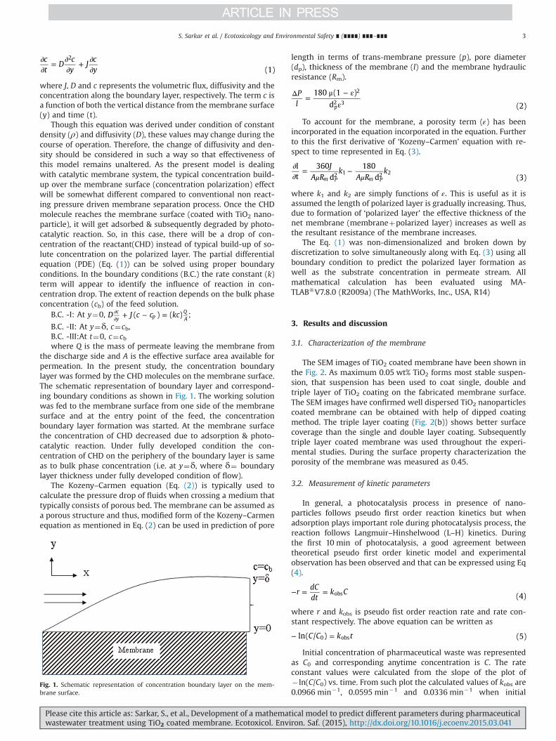
B.C. -II: At y¼δ, c¼cb,B.C. -III:At t¼0, c¼cbwhere Q is the mass of permeate leaving the membrane from
the discharge side and A is the effective surface area available forpermeation. In the present study, the concentration boundarylayer was formed by the CHD molecules on the membrane surface.The schematic representation of boundary layer and correspond-ing boundary conditions as shown in Fig. 1. The working solutionwas fed to the membrane surface from one side of the membranesurface and at the entry point of the feed, the concentrationboundary layer formation was started. At the membrane surfacethe concentration of CHD decreased due to adsorption & photo-catalytic reaction. Under fully developed condition the con-centration of CHD on the periphery of the boundary layer is sameas to bulk phase concentration (i.e. at y¼δ, where δ¼ boundarylayer thickness under fully developed condition of flow).
The Kozeny–Carmen equation (Eq. (2)) is typically used tocalculate the pressure drop of fluids when crossing a medium thattypically consists of porous bed. The membrane can be assumed asa porous structure and thus, modified form of the Kozeny–Carmenequation as mentioned in Eq. (2) can be used in prediction of pore
Fig. 1. Schematic representation of concentration boundary layer on the mem-brane surface.
Please cite this article as: Sarkar, S., et al., Development of a mathematwastewater treatment using TiO2 coated membrane. Ecotoxicol. Envi
length in terms of trans-membrane pressure (p), pore diameter(dp), thickness of the membrane (l) and the membrane hydraulicresistance (Rm).
Pl
180 (1 )
d (2)p
2
2 3
Δ =μ − ε
ε
To account for the membrane, a porosity term (ε) has beenincorporated in the equation incorporated in the equation. Furtherto this the first derivative of ‘Kozeny–Carmen’ equation with re-spect to time represented in Eq. (3).
JA R
kA R
klt
360d
180d (3)m P m P
2 1 2 2μ μ
∂∂
= −
where k1 and k2 are simply functions of .ε This is useful as it isassumed the length of polarized layer is gradually increasing. Thus,due to formation of ‘polarized layer’ the effective thickness of thenet membrane (membraneþpolarized layer) increases as well asthe resultant resistance of the membrane increases.
The Eq. (1) was non-dimensionalized and broken down bydiscretization to solve simultaneously along with Eq. (3) using allboundary condition to predict the polarized layer formation aswell as the substrate concentration in permeate stream. Allmathematical calculation has been evaluated using MA-TLABsV7.8.0 (R2009a) (The MathWorks, Inc., USA, R14)
3. Results and discussion
3.1. Characterization of the membrane
The SEM images of TiO2 coated membrane have been shown inthe Fig. 2. As maximum 0.05 wt% TiO2 forms most stable suspen-sion, that suspension has been used to coat single, double andtriple layer of TiO2 coating on the fabricated membrane surface.The SEM images have confirmed well dispersed TiO2 nanoparticlescoated membrane can be obtained with help of dipped coatingmethod. The triple layer coating (Fig. 2(b)) shows better surfacecoverage than the single and double layer coating. Subsequentlytriple layer coated membrane was used throughout the experi-mental studies. During the surface property characterization theporosity of the membrane was measured as 0.45.
3.2. Measurement of kinetic parameters
In general, a photocatalysis process in presence of nano-particles follows pseudo first order reaction kinetics but whenadsorption plays important role during photocatalysis process, thereaction follows Langmuir–Hinshelwood (L–H) kinetics. Duringthe first 10 min of photocatalysis, a good agreement betweentheoretical pseudo first order kinetic model and experimentalobservation has been observed and that can be expressed using Eq(4).
rdCdt
k C (4)obs− = =
where r and kobs is pseudo fist order reaction rate and rate con-stant respectively. The above equation can be written as
C C k tln( / ) (5)0 obs− =
Initial concentration of pharmaceutical waste was representedas C0 and corresponding anytime concentration is C. The rateconstant values were calculated from the slope of the plot of� ln(C/C0) vs. time. From such plot the calculated values of kobs are0.0966 min�1, 0.0595 min�1 and 0.0336 min�1 when initial
ical model to predict different parameters during pharmaceuticalron. Saf. (2015), http://dx.doi.org/10.1016/j.ecoenv.2015.03.041i
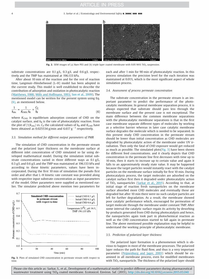
Fig. 2. SEM images of (a) Bare PES and (b) triple layer coated membrane with 0.05 Wt% TiO2 suspension.
S. Sarkar et al. / Ecotoxicology and Environmental Safety ∎ (∎∎∎∎) ∎∎∎–∎∎∎4
substrate concentrations are 0.1 g/L, 0.3 g/L and 0.6 g/L respec-tively and the TMP has maintained at 196.133 kPa.
After about 10 min of the reaction and for the rest of reactiontime, Langmuir–Hinshelwood (L–H) model has been adopted inthe current study. This model is well established to describe thecontribution of adsorption and oxidation in photocatalytic reaction(Matthews, 1988; Mills and Hoffmann, 1993; Son et al., 2009). Thementioned model can be written for the present system using Eq.(6), as mentioned below.
k K kCk
1 1(6)obs CHDG R R
0= +
where KCHD is equilibrium adsorption constant of CHD on thecatalyst surface, and kR is the rate of photocatalytic reaction. Fromthe plot of (1/kobs) vs. C0 the calculated values of kR and KCHD havebeen obtained as 0.025534 g/min and 6.617 g�1 respectively.
3.3. Simulation method for different output parameters of PMR
The simulation of CHD concentration in the permeate streamand the polarized layer thickness on the membrane surface atdifferent inlet concentration of CHD simulated so far using de-veloped mathematical model. During the simulation initial sub-strate concentrations varied in three different ways as 0.1 g/L,0.3 g/L and 0.6 g/L and the TMP was maintained at 196.133 kPa andaccording to these kinetic parameters, values have been in-corporated. During the first 10 min of simulation the pseudo firstorder and after that L–H kinetic rate constant was provided alongwith respective input substrate concentration as input parametersof the model. Other parameters were supplied as mentioned ear-lier. The simulator predicted above mention two parameters for
Fig. 3. Plots of simulated CHD concentration in permeate stream with respect totime.
Please cite this article as: Sarkar, S., et al., Development of a mathematwastewater treatment using TiO2 coated membrane. Ecotoxicol. Env
each and after 1 min for 90 min of photocatalytic reaction. In thisprocess simulation the precision level for the each iteration wasmaintained at 0.01%, which is the most significant aspect of wholesimulation process.
3.4. Assessment of process permeate concentration
The substrate concentration in the permeate stream is an im-portant parameter to predict the performance of the photo-catalytic membrane. In general membrane separation process, it isalways expected that substrate should pass less through themembrane surface and the present case is not exceptional. Themain difference between the common membrane separationswith the photocatalytic membrane separations is that in the firstcase membrane separate different types of molecules by workingas a selective barrier whereas in later case catalytic membranesurface degrades the molecule which is needed to be separated. Inthis present study CHD concentration in the permeate streamshould be lower than initial concentration as CHD molecules aredegraded by photocatalytic action of the membrane under UV ir-radiation. Then only the fatal of CHD exposure would get reducedas much as possible. The simulated plots(Fig. 3) have been shownfor different feed concentrations. and it clearly depicts that CHDconcentration in the permeate line first decreases with time up to10 min, then it starts to increase up to certain value and again itfalls to an approximately steady state value. It may be happenedbecause the target particles would instantly react with the catalystparticles on the membrane surface initially for first 10 min. Duringphotocatalysis process, the target molecules are adsorbed on thecatalyst surface first then it degraded under photocatalytic actionof TiO2 nanoparticles (Sarkar et al., 2015). According to that, atinitial stage of reaction fresh nanoparticles on the membranesurface absorbed more CHD molecules and eventually those aredegraded but after 10 min there were no such catalyst particles areleft for further degradation. As a result, the membrane showedpoor catalytic performance which, encouraged for permeation oftarget molecule through the membrane under constant TMP. Aftersome interval the catalytic surface regain its activity by desorbingby-products generated from CHD during photocatalysis and hence,the nanoparticles again took part in photochemical reaction aswell as the CHD concentration started to fall again in permeateline. The above mentioned possible explanation may be helpful tounderstand the working principle of photocatalytic membrane.
3.5. Prediction of polarized layer thickness
The polarized layer formation is a phenomenon which is ob-vious to happen in most of the membrane processes. The polarizedlayer reduces the path for fluid flow, and thus is a very importantparameter (Peijnenburg and Jager, 2003) which should be ex-amined in all membrane process, even for modified membraneswith TiO2 nanoparticle. The thickness of the polarized layer should
ical model to predict different parameters during pharmaceuticaliron. Saf. (2015), http://dx.doi.org/10.1016/j.ecoenv.2015.03.041i
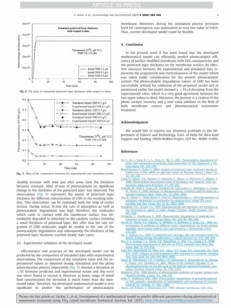
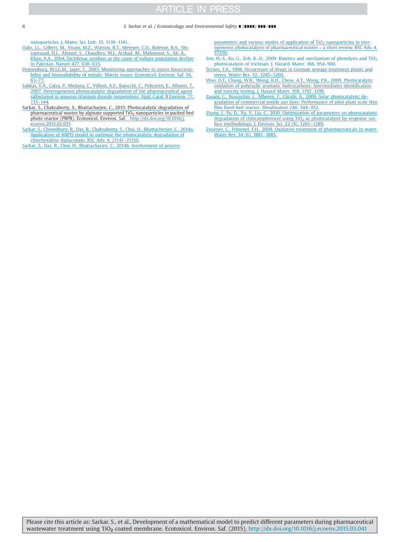
Fig. 4. The plots of simulated polarized layer thickness with respect to time.
Fig.. 5. Plots of the comparison between the experimental and simulation results.
S. Sarkar et al. / Ecotoxicology and Environmental Safety ∎ (∎∎∎∎) ∎∎∎–∎∎∎ 5
steadily increase with time and after some time the thicknessbecomes constant. After 10 min of photocatalysis no significantchange in the thickness of the polarized layer was observed. Theobservations (Fig. 4) represents the extent of polarized layerthickness for different concentration of CHD in the working solu-tion. This observation can be explained with the help of earliersection. During initial 10 min the rate of adsorption as well asphotocatalytic degradation was high therefore, the moleculeswhich came in contact with the membrane surface was im-mediately degraded or adsorbed on the catalytic surface resultinga small thickness of polarized layer. But, after that the rate mi-gration of CHD molecules might be similar to the rate of thephotocatalytic degradation and subsequently the thickness of thepolarized layer thickness reached steady state value.
3.6. Experimental validation of the developed model
Effectiveness and accuracy of the developed model can bepredicted by the comparison of simulated data with experimentalobservations. The comparison of the simulated value and the ex-perimental values as obtained during simulation and the photomineralization process respectively (Fig. 5) showed a deviation of75% between predicted and experimental values and this errorwas never found to exceed it. However at lower range of initialfeed concentration the deviation is much lower than the men-tioned value. Therefore, the developed mathematical model is verysignificant to predict the performance of photocatalytic
Please cite this article as: Sarkar, S., et al., Development of a mathematwastewater treatment using TiO2 coated membrane. Ecotoxicol. Envi
membrane. Moreover, during the simulation process precisionlevel for convergence was maintained at very low value of 0.01%.Thus, current developed model could be feasible.
4. Conclusion
In the present work it has been found that the developedmathematical model can efficiently predict photocatalytic effi-ciency of surface modified membrane with TiO2 nanoparticles andthe polarized layer thickness on the membrane surface. An effec-tive closeness between the experimental and simulated data re-presents the pragmatism and meticulousness of the model whichwas taken under consideration for the present photocatalyticsystem. The photocatalytic degradation nature of CHD has beensuccessfully utilized for validation of the proposed model and asmentioned earlier the model showed a 75% of deviation from theexperimental value, which is a very good agreement between thetwo types values in deed. Moreover, the present is a citation of thephoto catalyst recovery and a new value addition in the field ofboth membrane science and pharmaceutical wastewatertreatment.
Acknowledgment
We would like to express our immense gratitude to the De-partment of Science and Technology, Govt. of India for their kindsupport and funding (INDO-KOREA Project, DST No.: ROKP-11109).
References
An, T., An, J., Yang, H., Li, G., Feng, H., Nie, X., 2011. Photocatalytic degradation ki-netics and mechanism of antivirus drug-lamivudine in TiO2 dispersion. J. Ha-zard. Mater 197, 229–236.
Bhattacharjee, C., Datta, S., 2003. Analysis of polarized layer resistance during ul-trafiltration of PEG-6000: an approach based on filtration theory. J. Mem. Sci.33, 115–126.
Calza, P., Sakkas, V.A., Medana, C., Baiocchi, C., Dimou, A., Pelizzetti, E., Albanis, T.,2006. Photocatalytic degradation study of diclofenac over aqueous TiO2 sus-pensions. Appl. Catal. B Environ. 67, 197–205.
Carballa, M., Omil, F., Lema, J.M., Llompart, M., Garcia-Jares, C., Rodriguez, I., Gomez,M., Ternes, T., 2004. Behavior of pharmaceuticals, cosmetics and hormones in asewage treatment plant. Water Res. 38, 2918–2926.
Das, R., Sarkar, S., Chakraborty, S., Choi, H., Bhattacharjee, C., 2014. Remediation ofantiseptic components in wastewater by photocatalysis using TiO2 nano-particles. Ind. Eng. Chem. Res. 53 (8), 3012–3020.
Daughton, C.G., Ternes, T.A., 1999. Pharmaceuticals and personal care products inthe environment: agents of subtle change? Environ. Health Perspect. 107,907–938.
Devipriya, S., Yesodharan, S., 2005. Photocatalytic degradation of pesticide con-taminants in water. Sol. Energy Mater. Sol. Cells 86, 309–348.
Hirsch, R., Ternes, T.A., Haberer, K., Mehlich, A., Ballwanz, F., Kratz, K.L., 1998. De-termination of antibiotics in different water compartments via liquid chroma-tography–electrospray tandem mass spectrometry. J. Chromatogr. A 815,213–223.
Ho, C., Zydney, A.L., 2000. A combined pore blockage and cake filtration model forprotein fouling during microfiltration. J. Colloid Interface Sci. 232, 389–399.
Hsu, Y.-Y., Hsiung, T.-L., Wang, H.P., Fukushima, Y., Wei, Y.-L., Chang, J.-E., 2008.Photocatalytic degradation of spill oils on TiO(2) nanotube thin films. Mar.Pollut. Bull. 57, 873–876.
Kidd, K.A., Blanchfield, P.J., Mills, K.H., Palace, V.P., Evans, R.E., Lazorchak, J.M., Flick,R.W., 2007. Collapse of a fish population after exposure to a synthetic estrogen.Proc. Natl. Acad. Sci. USA 104, 8897–8901.
Lange, R., Hutchinson, T.H., Croudace, C.P., Siegmund, F., Schweinfurth, H., Hampe,P., Panter, G.H., Sumpter, J.P., 2001. Effects of the synthetic estrogen 17 al-phaethinylestradiol on the life-cycle of the fathead minnow(Pimephales pro-melas). Environ. Toxicol. Chem. 20, 1216–1227.
Matthews, R.W., 1988. Kinetics of photocatalytic oxidation of organic solutes overtitanium dioxide. J. Catal. 111, 264–272.
Mills, G., Hoffmann, M.R., 1993. Photocatalytic degradation of pentachlorophenolon TiO2 particles: identification of intermediates and mechanism of reaction.Environ. Sci. Technol. 27, 1681–1689.
Nunes, S.P., Schultz, J., Peinemann, K.V., 1996. Silicone membranes with silica
ical model to predict different parameters during pharmaceuticalron. Saf. (2015), http://dx.doi.org/10.1016/j.ecoenv.2015.03.041i
S. Sarkar et al. / Ecotoxicology and Environmental Safety ∎ (∎∎∎∎) ∎∎∎–∎∎∎6
nanoparticles. J. Mater. Sci. Lett. 15, 1139–1141.Oaks, J.L., Gilbert, M., Virani, M.Z., Watson, R.T., Meteyer, C.U., Rideout, B.A., Shi-
vaprasad, H.L., Ahmed, S., Chaudhry, M.J., Arshad, M., Mahmood, S., Ali, A.,Khan, A.A., 2004. Diclofenac residues as the cause of vulture population declinein Pakistan. Nature 427, 630–633.
Peijnenburg, W.J.G.M., Jager, T., 2003. Monitoring approaches to assess bioaccessi-bility and bioavailability of metals: Matrix issues. Ecotoxicol. Environ. Saf. 56,63–77.
Sakkas, V.A., Calza, P., Medana, C., Villioti, A.E., Baiocchi, C., Pelizzetti, E., Albanis, T.,2007. Heterogeneous photocatalytic degradation of the pharmaceutical agentsalbutamol in aqueous titanium dioxide suspensions. Appl. Catal. B Environ. 77,135–144.
Sarkar, S., Chakraborty, S., Bhattacharjee, C., 2015. Photocatalytic degradation ofpharmaceutical wastes by alginate supported TiO2 nanoparticles in packed bedphoto reactor (PBPR). Ecotoxicol. Environ. Saf. . http://dx.doi.org/10.1016/j.ecoenv.2015.02.035
Sarkar, S., Chowdhury, R., Das, R., Chakraborty, S., Choi, H., Bhattacherjee, C., 2014a.Application of ANFIS model to optimise the photocatalytic degradation ofchlorhexidine digluconate. RSC Adv. 4, 21141–21150.
Sarkar, S., Das, R., Choi, H., Bhattacharjee, C., 2014b. Involvement of process
Please cite this article as: Sarkar, S., et al., Development of a mathematwastewater treatment using TiO2 coated membrane. Ecotoxicol. Env
parameters and various modes of application of TiO2 nanoparticles in eter-ogeneous photocatalysis of pharmaceutical wastes – a short review. RSC Adv. 4,57250.
Son, H.-S., Ko, G., Zoh, K.-D., 2009. Kinetics and mechanism of photolysis and TiO2
photocatalysis of triclosan. J. Hazard. Mater. 166, 954–960.Ternes, T.A., 1998. Occurrence of drugs in German sewage treatment plants and
rivers. Water Res. 32, 3245–3260.Woo, O.T., Chung, W.K., Wong, K.H., Chow, A.T., Wong, P.K., 2009. Photocatalytic
oxidation of polycyclic aromatic hydrocarbons: Intermediates identificationand toxicity testing. J. Hazard Mater. 168, 1192–1199.
Zayani, G., Bousselmi, L., Mhenni, F., Ghrabi, A., 2009. Solar photocatalytic de-gradation of commercial textile azo dyes: Performance of pilot plant scale thinfilm fixed-bed reactor. Desalination 246, 344–352.
Zhang, J., Fu, D., Xu, Y., Liu, C., 2010. Optimization of parameters on photocatalyticdegradation of chloramphenicol using TiO2 as photocatalyist by response sur-face methodology. J. Environ. Sci. 22 (8), 1281–1289.
Zwiener, C., Frimmel, F.H., 2000. Oxidative treatment of pharmaceuticals in water.Water Res. 34 (6), 1881–1885.
ical model to predict different parameters during pharmaceuticaliron. Saf. (2015), http://dx.doi.org/10.1016/j.ecoenv.2015.03.041i