Development of a Design Methodology for Cloud Distributed ...
18
Citation: Sechenev, S.; Ryadchikov, I.; Gusev, A.; Lampezhev, A.; Nikulchev, E. Development of a Design Methodology for Cloud Distributed Control Systems of Mobile Robots. J. Sens. Actuator Netw. 2022, 11, 1. https://doi.org/10.3390/ jsan11010001 Academic Editor: Thomas Newe Received: 2 November 2021 Accepted: 21 December 2021 Published: 26 December 2021 Publisher’s Note: MDPI stays neutral with regard to jurisdictional claims in published maps and institutional affil- iations. Copyright: © 2021 by the authors. Licensee MDPI, Basel, Switzerland. This article is an open access article distributed under the terms and conditions of the Creative Commons Attribution (CC BY) license (https:// creativecommons.org/licenses/by/ 4.0/). Journal of Actuator Networks Sensor and Article Development of a Design Methodology for Cloud Distributed Control Systems of Mobile Robots Semyon Sechenev 1 , Igor Ryadchikov 1 , Alexander Gusev 2 , Abas Lampezhev 3 and Evgeny Nikulchev 4, * 1 Laboratory of Robotics and Mechatronics, Kuban State University, 350040 Krasnodar, Russia; [email protected] (S.S.); [email protected] (I.R.) 2 Institute of Mechanics, Robotics, Engineering of Transport and Technical Systems, Kuban State Technological University, 350072 Krasnodar, Russia; [email protected] 3 Institute of Design and Technology Informatics, Russian Academy of Sciences, 127055 Moscow, Russia; [email protected] 4 Department of Digital Data Processing Technologies, MIREA—Russian Technological University, 119454 Moscow, Russia * Correspondence: [email protected] Abstract: This article addresses the problem of cloud distributed control systems development for mobile robots. The authors emphasize the lack of a design methodology to guide the process of the development in accordance with specific technical and economic requirements for the robot. On the analysis of various robots architectures, the set of the nine most significant parameters are identified to direct the development stage by stage. Based on those parameters, the design methodology is proposed to build a scalable three-level cloud distributed control system for a robot. The application of the methodology is demonstrated on the example of AnyWalker open source robotics platform. The developed methodology is also applied to two other walking robots illustrated in the article. Keywords: distributed control systems; walking robots control; cloud robotics 1. Introduction The control infrastructure of modern mobile robots represents a distributed multi- processor computing complex that includes computing modules on individual devices, external computing resources and means of exchanging data and commands over wireless networks [1]. For mass-produced mobile robots, both industrial and for use in the educa- tional system and experimental laboratories, a cloud computing board is often created [2], including software and hardware for controlling mechanisms, as well as receiving and processing data from sensors; the solution of operational tasks is left on local nodes [3]. For the same type of robots, the use of a single cloud computing infrastructure improves the technical and economic characteristics, since cloud technologies reduce the requirements for expensive computing resources of each individual mobile robot [4]. For robotic systems that process large amounts of data and synthesize control actions for large dimensions of degrees of freedom, the task of forming an external computing infrastructure is one of the most important. Distributed control architectures are relevant when developing information and control systems for mobile robotic platforms that move in a heterogeneous environment with the need to recognize dynamic obstacles and interact with different objects or people. The implementation of these functions requires significant computational resources, which are not available due to restrictions on power consumption and the di- mensions of the mobile robot. The use of cloud services with the use of wireless computer networks allows us to solve the tasks set, provided that the limit on the maximum feedback delay in the robot control loop is met [5,6]. The development of the element base, architectures of distributed computing com- plexes, the spread and improvement of the quality of wireless data transmission networks J. Sens. Actuator Netw. 2022, 11, 1. https://doi.org/10.3390/jsan11010001 https://www.mdpi.com/journal/jsan
-
Upload
khangminh22 -
Category
Documents
-
view
1 -
download
0
Transcript of Development of a Design Methodology for Cloud Distributed ...

�����������������
Citation: Sechenev, S.; Ryadchikov, I.;
Gusev, A.; Lampezhev, A.; Nikulchev,
E. Development of a Design
Methodology for Cloud Distributed
Control Systems of Mobile Robots. J.
Sens. Actuator Netw. 2022, 11, 1.
https://doi.org/10.3390/
jsan11010001
Academic Editor: Thomas Newe
Received: 2 November 2021
Accepted: 21 December 2021
Published: 26 December 2021
Publisher’s Note: MDPI stays neutral
with regard to jurisdictional claims in
published maps and institutional affil-
iations.
Copyright: © 2021 by the authors.
Licensee MDPI, Basel, Switzerland.
This article is an open access article
distributed under the terms and
conditions of the Creative Commons
Attribution (CC BY) license (https://
creativecommons.org/licenses/by/
4.0/).
Journal of
Actuator NetworksSensor and
Article
Development of a Design Methodology for Cloud DistributedControl Systems of Mobile Robots
Semyon Sechenev 1, Igor Ryadchikov 1, Alexander Gusev 2 , Abas Lampezhev 3 and Evgeny Nikulchev 4,*
1 Laboratory of Robotics and Mechatronics, Kuban State University, 350040 Krasnodar, Russia;[email protected] (S.S.); [email protected] (I.R.)
2 Institute of Mechanics, Robotics, Engineering of Transport and Technical Systems,Kuban State Technological University, 350072 Krasnodar, Russia; [email protected]
3 Institute of Design and Technology Informatics, Russian Academy of Sciences, 127055 Moscow, Russia;[email protected]
4 Department of Digital Data Processing Technologies, MIREA—Russian Technological University,119454 Moscow, Russia
* Correspondence: [email protected]
Abstract: This article addresses the problem of cloud distributed control systems development formobile robots. The authors emphasize the lack of a design methodology to guide the process of thedevelopment in accordance with specific technical and economic requirements for the robot. On theanalysis of various robots architectures, the set of the nine most significant parameters are identifiedto direct the development stage by stage. Based on those parameters, the design methodology isproposed to build a scalable three-level cloud distributed control system for a robot. The applicationof the methodology is demonstrated on the example of AnyWalker open source robotics platform.The developed methodology is also applied to two other walking robots illustrated in the article.
Keywords: distributed control systems; walking robots control; cloud robotics
1. Introduction
The control infrastructure of modern mobile robots represents a distributed multi-processor computing complex that includes computing modules on individual devices,external computing resources and means of exchanging data and commands over wirelessnetworks [1]. For mass-produced mobile robots, both industrial and for use in the educa-tional system and experimental laboratories, a cloud computing board is often created [2],including software and hardware for controlling mechanisms, as well as receiving andprocessing data from sensors; the solution of operational tasks is left on local nodes [3]. Forthe same type of robots, the use of a single cloud computing infrastructure improves thetechnical and economic characteristics, since cloud technologies reduce the requirementsfor expensive computing resources of each individual mobile robot [4]. For robotic systemsthat process large amounts of data and synthesize control actions for large dimensionsof degrees of freedom, the task of forming an external computing infrastructure is oneof the most important. Distributed control architectures are relevant when developinginformation and control systems for mobile robotic platforms that move in a heterogeneousenvironment with the need to recognize dynamic obstacles and interact with differentobjects or people. The implementation of these functions requires significant computationalresources, which are not available due to restrictions on power consumption and the di-mensions of the mobile robot. The use of cloud services with the use of wireless computernetworks allows us to solve the tasks set, provided that the limit on the maximum feedbackdelay in the robot control loop is met [5,6].
The development of the element base, architectures of distributed computing com-plexes, the spread and improvement of the quality of wireless data transmission networks
J. Sens. Actuator Netw. 2022, 11, 1. https://doi.org/10.3390/jsan11010001 https://www.mdpi.com/journal/jsan

J. Sens. Actuator Netw. 2022, 11, 1 2 of 18
determines the directions for improving the methods of theoretical analysis and experimen-tal research of the functioning of computing complexes to improve the technical, economicand operational characteristics of mobile robots.
Currently, open-source robotics (OSR) platforms have been created for the developmentof mobile robot control systems, which provide the unified drawings, diagrams, software andinfrastructure for implementing the final ideas of third-party developers. Open platformsinclude RepRap [7,8], FarmBot [9], Yale Open Hand Project [10], e-puck mobile robot [11],Ardumower [12], Hexy [13], OpenROV [14], Pulurobotics [15], Thymio [16], Vorpal theHexapod [17], Open-source Micro-robotic Project [18], Oscar [19], AnyWalker [20,21], dronessuch as ArduPilot [22,23], OpenPilot [24], LibrePilot [25], Paparazzi Project [26], Slugs [27],PX4 autopilot [28], humanoid robots such as iCub [29], DARwln-OP [30], InMoov [31],Poppy-project [32], DoraBot [33], NimbRo-OP [34], r-One [35], personal assistants such asAutobed [36], etc.
However, the peculiarities of the structures, the tasks to be solved [37] and the criteriafor the quality of functioning require the development of specialized methods aimed atimproving the technical and economic characteristics of computing complexes.
Thus, the aim of this research is the development of a design methodology for con-structing a three-level architecture of a walking robot computing complex with reactive,executive and application levels. The reactive level is implemented on the basis of a microcontroller that provides control of actuators, processing data from sensors, and monitoringenergy consumption. The executive level is implemented on a microprocessor with afull-fledged operating system, provides the basic functionality of the system (orientation inspace, video processing, state automaton) taking into account the limitations on computingpower and provides the access to the API. The application level is a distributed cloud soft-ware that solves computationally expensive tasks: physical modeling of motion, elementsof artificial intelligence, and collective behavior.
The difference between the architecture and its analogues consists in taking intoaccount the characteristics of computing resources and network infrastructure based on thespecified technical and economic requirements and operating conditions.
The methodology is built upon on the set of parameters derived from the analysisof technical and economic requirements and operating conditions, which determines thecharacteristics of the information and network infrastructure of a cloud computing complex.Nine major parameters are formulated that have a significant impact on the distribution ofresources between cloud services and local robot resources, as well as the characteristics ofdata transmission networks and acceptable delays in data exchange.
2. Background
The design of the on-board computer network includes the choice of the data exchangeinterface and the network topology. At the moment, the following types of interfaces fordata exchange between various parts and electronic units of control computing complexesare most common:
• CAN [38];• RS-232 [39];• RS-422 [40];• RS-485 [40];• Ethernet [41];• ARINC429 [42].
Let us summarize in a table the technical characteristics of the data exchange interfacesmentioned above (Table 1).

J. Sens. Actuator Netw. 2022, 11, 1 3 of 18
Table 1. Technical characteristics of the data exchange interfaces.
Name CAN RS-232 RS-422 RS-485 ARINC Ethernet
Bit rate, Mbit/s 1 1 10 10 0.1 1000Distance, m 40 10 10 10 - 100
Noise Immunity yes no yes yes yes yesCorrection of Errors yes no no no yes yes
Bus Arbitration yes no no no no yesReservation no no no no no no
Number of Devices 32 2 11 32 21 unlimited
As a result of our analysis of the advantages and disadvantages of interfaces fororganizing communication between the components of the control computing complex, itis advisable to apply the following solutions:
• Use the CAN interface for low-speed (up to 1 Mbit/s) communication between partsand blocks of the complex;
• At the stage of technical design, determine the technical need for physical separation ofdifferent subsystems according to their functional characteristics with the organizationof a common CAN bus within each subsystem;
• Use the Ethernet interface of 100BASE-TX and 1000BASE-T standards for high-speed(up to 1 Gbit/s) communication between parts and blocks of the complex;
• To communicate with components having RS-232, RS-422 and RS-485 interfaces, usethe appropriate interfaces.
One can organize the architectures of mobile robots into categories: laboratory stands,electric vehicles, humanoid robots, flight controllers, manipulators, etc.
Let us review the particular examples of each kind.Among laboratory stands, we should notice Cubli [43], which is a one-dimensional
prototype of a cube that can balance at an angle. The control system of the cube includestwo controlling units interlinked with the CAN interface. The first unit performs as themain controller and the second one controls the motor. The main unit is linked with theIMU sensors, the brake servo motor and the encoder. The SPI interface is used to connectthe main unit with the sensors of IMU. STM3210E debug board for the Cortex M3-coreSTM32F103E micro controller is used to implement the main controller. The reasons forchoosing that board include the rapid prototyping ability and the manifold support ofthe community. The operating system is FreeRTOS, a real-time operating system, whichcombines prioritization of multitasking with the relatively small kernel size of only 4 KB.
We should also mention the triple inverted pendulum on a cart described in [44]. Themain controller is organized upon the dSPACE DS1103 [45] module for measurements andcontrol. All the initial search and experiments were conducted in the MATLAB/Simulink.Some of the values were pre-calculated and the lookup tables were built on the basis oftheir interpolation. With the dSPACE DS1103 all the needed I/O configuration could bedone in the MATLAB/Simulink environment and then run automatically in compiled formon the device. Thus, the speed of prototyping increased dramatically while the number ofexperiments was reduced.
Next, we should look at the electronic control units (ECU) of electric vehicles. TheECUs are used to group the electronic systems of the vehicle in the unified hardwareand software architecture. Thus, the ECU can be responsible for control of more thanone electronic subsystems of the vehicle, nevertheless multiple ECUs can be applied ifappropriate. The second leads to the problem of reducing the number of wires withwhich ECUs are connected. The CAN Network can be pointed out as the most frequentsolution of that problem [46–49]. The CAN is able to transfer data efficiently even when theelectromagnetic interference is present. The transfer rate can be close to 1 Mbit/s, which isquite enough for a variety of tasks. In [46], the example of CAN Network providing thecommunication with all the devices, except for GPS, is described. To meet the requirementsof specific devices, such as special network settings, filtering or isolation, the multiple
J. Sens. Actuator Netw. 2022, 11, 1 4 of 18
subnets were organized with the network gateways (ADFWeb or dSPACE MicroAutoBox)to link them all. For the implementation of the main controller over all ECUs in the vehicle,the dSPACE MicroAutobox II was chosen. The PC of the car built upon Intel P8700 with1 GB of RAM and 500 GB of hard disk space is Ethernet-connected with the dSPACEMicroAutoBox II. The dSPACE ControlDesk is used to make logs and perform experiments.To provide the fast prototyping the dSpace ControlDesk is binded with Simulink.
CAN bus is also very common in bipedal walking robots. For example, in HRP3 [50],iCub [51], and DRC-HYBO + [52]. EtherCAT [53,54] is also quite frequent. It solves theproblem of the CAN bus, i.e., the impossibility of high-frequency access to low-levelcontrollers (1 kHz) [54]. As it was noted in [55], PCI as well as PCI104 and PCIe arefrequently used to link the network cards, motherboards and analog-to-digital converters.To interlink the motors and encoders, the CAN or EtherCAT are used, whose strength isreliability. The low limited bandwidth of the CAN bus should be noted (1 Mbit/s) and thedisability of connecting lots of devices. To avoid this, several tires are frequently used in ahumanoid kind of robots [50,51]. SERCOS III can be found in some robots [55], which hasthe similar principles to EtherCAT as well as similar performance. Consider the Walkmansoftware and hardware architecture [53]. To control the movements of the robot, a COMExpress computing module based on a Pentium i7 quad core processor was used. TheEthercat Master Device Manager is launched with it. It organizes the operation of theEthercat slaves in terms of synchronization, real-time receiving and sending the data abouttheir relative position. YARP [56] is applied as the remote access middleware for robotmotors, as it combines high speed with low latency. In the initial stage of the development,there was a direct communication between the YarpServer and ROS Core. However, such achoice led to the frequent connection losses, and the interconnected YARP/ROS serversmay not recover from this. To avoid that, the PC for control and the robot were separatedwith their own RosCore and YarpServer running.
EtherCAT is a fairly popular solution, especially for complex systems with a largenumber of sensors. For example, there are projects for robotic skin [57], four-legged [58,59]and six-legged [60–62] robots, medical rehabilitation robots and exoskeletons [63–65]. Hereis a brief description of the architecture of another human-like robot on EtherCAT and ROS,Talos Pyr‘ene, developed by PAL-Robotics [54]. The robot is equipped with two computers,each with a dual i7 CPU at 2.8 GHz, eight cores due to multi-threading. However, dueto the fact that the RT-PREEMPT real-time operating system is used, only four cores areavailable on the control computer. Eight cores are available on the computer responsiblefor vision and high-level computing. All PAL-Robotics robots, including Talos Pyr‘ene,are deeply integrated with the robotic operating system (ROS). The operating system isUbuntu 14.04 LTS. Ros_control is actively used, which allows one to quickly move betweensimulation and tests on a real robot. The authors, however, note that although ROS controlis easier to use than openRTM, it currently yields to openRTM in layout [66].
Aircraft flight controller architectures often include Vicon‘s motion capture system.The frequency of the system and the number of sensors used may vary. For example, inarticle [67], a Vicon system with a frequency of 200 Hz was selected. Vicon connects viaEthernet to the ground station on which the ROS is installed. Then, the data is sent viaa UDP bridge via MAVLink (micro air vehicle communication) protocol to Pixhawk px4autopilot from which commands to engine drivers are sent via I2C. In addition, there arevariants that use the ROS-Matlab Bridge [68].
To control KUKA industrial manipulators Kuka KR C4 is used. The control is orga-nized via the Central Cabine Control Unit (CCU), which interfaces with all the componentsas the main board. The KUKA Control PC (KPC) provides the user interface. The motorcontrols are provided via the KUKA Servo Pack (KSP). The robot power system has itsown controller and is named KUKA Power Pack (KPP). The collecting of motor positionand temperature data is performed with the Resolver Digital Converter (RDC). The safeoperation of the robot is done with the Safety Interface Board (SIB). Moreover, a board forEthernet, Dual NIC and SmartPAD as well as Controller System Panel (CSP) are connected

J. Sens. Actuator Netw. 2022, 11, 1 5 of 18
to the CCU. SmartPAD serves as the operator panel. The following five interfaces are usedto conned the above listed items to the CCU:
• KUKA Extension Bus (KEB);• KUKA System Bus (KSB);• KUKA Service Interface (KSI);• KUKA (KCB);• KUKA (KOI).
The connection between the controller and the industrial Internet networks such asDeivceNet and PROFIBUS can be made via the KEB interface. The developers also claimthe support of INTERBUS, EtherCAT, Ethernet/IP, VARANBUS and PROFINET with theKEB interface. Interesting to note, that Univeral Robots E-series collaborative robots havea control box which provides the support of only three industrial networks standards:PROFINET, EthernetIP and ModbusTCP. Besides, all the standards are described with thesoft real time, indeterminacy and lack of guarantees for the transmission delay [69].
3. Development of a Cloud Control Architecture and Derivation of the Methodology
The scheme of the problem of the cloud computing architecture development isdepicted in Figure 1.
Figure 1. The scheme of the problem: on the left side there is a variety of users connecting to thecloud robotic control platform with a thin client (mobile device, laptop, etc.); in the center, there is acloud distributed control platform organized (in a common case) as a set of web-servers distributedacross the world, balancing the traffic load and providing the simultaneous access for users to therobotic control web-services, the back-end of the control platform also performs heavy computationsfor the robots such as assessing the robot‘s environment with the computer vision techniques andautomatic feedback-based correction of the robots parameters; the right part of the picture is a set ofrobots performing the operations under the control of the users from the left side, the communicationbetween the user and the robot is done with the cloud distributed control platform.
We demonstrate the process of the cloud computing architecture development onthe example of the AnyWalker walking mobile robot (Figure 2). AnyWalker is a non-anthropomorphic walking robot with the system of compensation of external impacts withmotor-wheels that can stabilize the robotic system in 3 dimensions [20].
For the robot under consideration, taking into account the application of Robot Oper-ating System (an open platform with plenty of sensor interfaces), a functional diagram ofthe distribution of tasks and data exchange channels in the cloud architecture of the controlcomputing unit is depicted in Figure 3.
Analysis of the requirements for solving problems on the choice of software, hardwareand network solutions for building a cloud platform, theoretical and experimental studieson a number of implementations of walking robots made it possible to form a three-layer architecture of a cloud-based distributed multiprocessor control computing complex(Figure 4):
1. A reactive level based on a micro-controller that provides control of actuators, dataprocessing from sensors, and control of energy consumption.

J. Sens. Actuator Netw. 2022, 11, 1 6 of 18
2. The executive level is implemented on a microprocessor with a full-fledged operatingsystem, implements the basic functionality of the system (orientation in space, videoprocessing, state automaton), taking into account the limitations on computing powerand provides the access to the API.
3. The application layer represents a distributed cloud application software that solvescomputationally expensive tasks: physical modeling of motion, elements of artificialintelligence, and collective behavior.
Figure 2. AnyWalker mobile robot: the left picture and the central picture demonstrate the electronicinsides of the robot “head”, and the right picture demonstrates the standing prototype of the robotwithout the top casing of the “head”.
Figure 3. Functional diagram of the tasks and data distribution.
Figure 4. Three-level cloud control architecture.
J. Sens. Actuator Netw. 2022, 11, 1 7 of 18
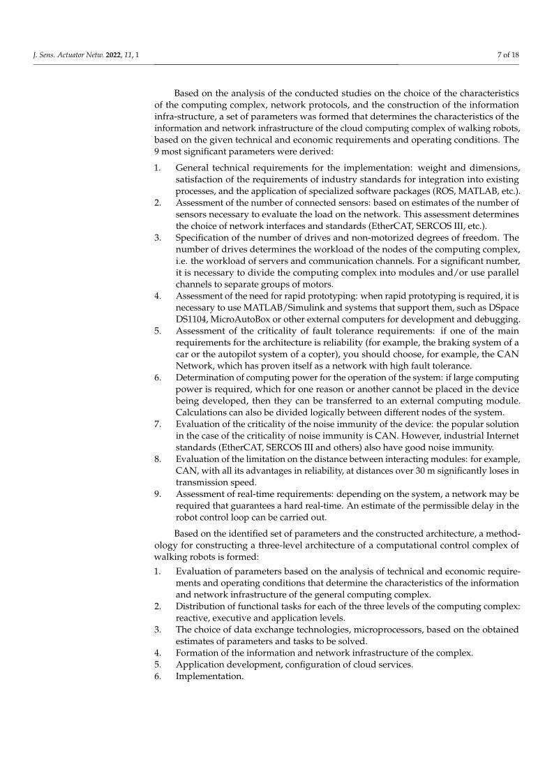
Based on the analysis of the conducted studies on the choice of the characteristicsof the computing complex, network protocols, and the construction of the informationinfra-structure, a set of parameters was formed that determines the characteristics of theinformation and network infrastructure of the cloud computing complex of walking robots,based on the given technical and economic requirements and operating conditions. The9 most significant parameters were derived:
1. General technical requirements for the implementation: weight and dimensions,satisfaction of the requirements of industry standards for integration into existingprocesses, and the application of specialized software packages (ROS, MATLAB, etc.).
2. Assessment of the number of connected sensors: based on estimates of the number ofsensors necessary to evaluate the load on the network. This assessment determinesthe choice of network interfaces and standards (EtherCAT, SERCOS III, etc.).
3. Specification of the number of drives and non-motorized degrees of freedom. Thenumber of drives determines the workload of the nodes of the computing complex,i.e. the workload of servers and communication channels. For a significant number,it is necessary to divide the computing complex into modules and/or use parallelchannels to separate groups of motors.
4. Assessment of the need for rapid prototyping: when rapid prototyping is required, it isnecessary to use MATLAB/Simulink and systems that support them, such as DSpaceDS1104, MicroAutoBox or other external computers for development and debugging.
5. Assessment of the criticality of fault tolerance requirements: if one of the mainrequirements for the architecture is reliability (for example, the braking system of acar or the autopilot system of a copter), you should choose, for example, the CANNetwork, which has proven itself as a network with high fault tolerance.
6. Determination of computing power for the operation of the system: if large computingpower is required, which for one reason or another cannot be placed in the devicebeing developed, then they can be transferred to an external computing module.Calculations can also be divided logically between different nodes of the system.
7. Evaluation of the criticality of the noise immunity of the device: the popular solutionin the case of the criticality of noise immunity is CAN. However, industrial Internetstandards (EtherCAT, SERCOS III and others) also have good noise immunity.
8. Evaluation of the limitation on the distance between interacting modules: for example,CAN, with all its advantages in reliability, at distances over 30 m significantly loses intransmission speed.
9. Assessment of real-time requirements: depending on the system, a network may berequired that guarantees a hard real-time. An estimate of the permissible delay in therobot control loop can be carried out.
Based on the identified set of parameters and the constructed architecture, a method-ology for constructing a three-level architecture of a computational control complex ofwalking robots is formed:
1. Evaluation of parameters based on the analysis of technical and economic require-ments and operating conditions that determine the characteristics of the informationand network infrastructure of the general computing complex.
2. Distribution of functional tasks for each of the three levels of the computing complex:reactive, executive and application levels.
3. The choice of data exchange technologies, microprocessors, based on the obtainedestimates of parameters and tasks to be solved.
4. Formation of the information and network infrastructure of the complex.5. Application development, configuration of cloud services.6. Implementation.

J. Sens. Actuator Netw. 2022, 11, 1 8 of 18
4. Implementation
In accordance with the developed methodology, a control computing complex wasdeveloped for AnyWalker (Figure 5).
Figure 5. AnyWalker control computing complex.
According to the methodology (Step 1), evaluation of parameters based on the analysisof technical and economic requirements and operating conditions has been done:
The first parameter, general technical requirements, for AnyWalker assumed a multi-purpose application in heterogeneous operating conditions and interaction with IoT devices.It was necessary to provide the possibility of connecting a large number of sensors fromdifferent manufacturers. Therefore, the choice was stopped on ROS, as a platform inthe open database of which there are interfaces for the overwhelming number of sensormanufacturers.
The second parameter, assessment of the number of connected sensors, lead to thechoice of high bandwidth onboard computer network based on UART as the number ofconnected sensors would be large.
The third parameter, determination of the number of drives and non-motorized de-grees of freedom, was equal to 27 motorized DoF, so it was necessary to provide syn-chronous operation of different drives with low latency. A search was made for variants ofthe distribution of the architecture of the computing complex.
The first evaluated version of the controller was STM32F4DISCOVERY Discoverykit based on a microcontroller STM32F407VG. The flash memory of the microcontrollercontains the program code for interacting with EPOS2 and GL-SVG-02/2, as well as thecode of the linear quadratic controller. This option is the simplest and most compact of allevaluated as the delays are minimal due to the simplicity of the system. However, whenscaling the system, it will be necessary to control three flywheels at once, it will be necessaryto connect a large number of sensors and increase the amount of program code for thefunctioning of the remaining systems of the robotic walking platform. In this case, a betterchoice would be to connect all devices to a controller with a Robotic Operating System,ROS. This was done in the following configuration.

J. Sens. Actuator Netw. 2022, 11, 1 9 of 18
Therefore, next stage of research was serial connection of two software controllers,physically located on different platforms. A Raspberry Pi 3 minicomputer with the Ubuntu16.04 operating system and the ROS Kinetic framework installed on it was connected to theSTM USART interface. An ASUS GL553V laptop with an Intel Core i7-7700HQ 2.80 GHzprocessor and 16 GB of RAM with the Windows 10 Home operating system, as well as theMATLAB version 2017b environment, was connected to the Raspberry Pi 3 via the UTPLAN interface.
The third controller option is STM32 NUCLEO-144 BOARD instead of STM32F4DISCOVERY in the second variant. The reason for this choice is the presence of an RJ45 connectoron the Ethernet board, which allows one to increase the speed of the connection betweenSTM and Raspberry Pi 3 from 4 to 100 Mbit/s. In this version STM, Raspberry Pi 3 andlaptop are connected to the switch.
The choice was made on the third variant of the architecture implementation, sincethis option allowed for the transmission of significant parameters of the state of the roboticsystem with a frequency of more than 100 Hz and the frequency of the control cycle of thestabilization algorithm of more than 200 Hz.
The evaluation of the fourth parameter, assessment for the need of rapid prototyping,lead to the conclusion that it is extremely important to be able to test various configurationsduring the prototyping process, which was made possible due to the ROS-MATLAB linkageand MATLAB code generation.
For the fifth parameter, assessment of the criticality of fault tolerance requirements,since reliability is a key requirement for the hardware and software architecture of thewalking platform, a CAN Network with high fault tolerance was used to organize theon-board network.
For the sixth parameter, determination of computing power for the operation of thesystem, a large computing power was required for robot stabilization and computer visionsensors operation processing, therefore an external MATLAB Speedgoat computer wasaccounted in the architecture.
For the seventh parameter, evaluation of the criticality of the noise immunity of thedevice, it was suggested that AnyWalker could operate in severe operating conditions withelectromagnetic fields of high intensity, so the CAN interface was chosen to provide thenoise immunity of the device.
For the eighth parameter, evaluation of the limitation on the distance between inter-acting modules, due to the compactness of the placement of onboard computing modulesof AnyWalker, CAN was used without a significant loss of data transfer speed on boardthe robot.
For the ninth parameter, assessment of real-time requirements, The necessity of esti-mating the permissible delay in the feedback loop was determined. After the analysis, itwas concluded that those delays should not exceed 200 ms.
At Step 2 of the methodology, the distribution of functional tasks was done for each ofthe three levels:
1. The reactive level is implemented on the STM32F407 micro controller. The IMU6050-based accelerometers/gyroscopes are polled via the I2C bus and the data is filteredusing the Madgwick sensor fusion algorithm. The movement of the flywheels and thecalculation of the speed are carried out using Maxon EPOS2 controllers with MaxonEC motors. Dynamixel MX106T actuators for robot legs are controlled via RS485,using a MAX485-based converter.
2. The executive level is based on the Raspberry Pi controller with the Robot OperatingSystem installed and is connected to the reactive level via the RS-485 bus. This levelimplements a simple autonomous behavior, a state machine, provides security andemergency shutdown. Data transfer to the cloud is carried out using Bluetooth, WiFior Ethernet, if necessary.
3. The application layer provides software installed on a personal computer or smart-phone, fully or partially located in the cloud. The application layer provides a high-

J. Sens. Actuator Netw. 2022, 11, 1 10 of 18
level user interface, supports the API of cloud voice recognition services, collectsdata from sensors and control commands for machine learning purposes, connectsseveral AnyWalker robots to provide a pattern of collective behavior. It is possibleto use algorithmic control support as an information service that allows third-partydevelopers to use the API to solve application problems. An application for theAndroid platform has also been developed to send motion commands to AnyWalkerand display the result.
At Steps 3–4 of the methodology, the choice of data exchange technologies, micropro-cessors, based on the obtained estimates of parameters was solved (Figure 6).
Figure 6. Implementation of the architecture of the AnyWalker control computing complex.
At Step 5, the application development and cloud services configuration were done [70–72].At Step 6, the architecture was finally implemented.
The core components in the scheme are the STM32F407 micro-controller for the pe-riphery and the Raspberry Pi 3 microcomputer serving as a top-level controller withinterfaces for the inter-operation of control software and a vast majority of clients withperipheral devices.
The controller of the periphery interacts wia the SPI protocol with a 9-axis inertial nav-igation system consisting of gyroscopes, accelerometers and magnetometers, an MPU9250chip. The equipment installed in the robot is controlled via the EPOS2 motor drivers withthe CAN communication protocol. The legs of the robot are driven with Dynamixel MX-106servomotors, the connection of which is done with the RS-485 protocol. The 6 elements perfoot servo series is used. Both buses are connected to two independent UART interfaces ofthe micro-controller.
The UART interface is used for the interaction of the upper-level controller and thecontroller of the periphery. The peripheral control codes are sent with that interface. Thedata from the INS sensors, the flywheels rotation speed, the values of the temperatureand the servo loads are requested with UART as well. The STM32F407 controller is alsoconnected via USB for debugging and downloading updated software using the STLinkv2 protocol.
Clients which implement various logic elements are also provided by the scheme.The high-level controller is connected to the clients via an Ethernet channel or a wirelessWiFi network.

J. Sens. Actuator Netw. 2022, 11, 1 11 of 18
In accordance with the chosen architecture, the main mathematical calculations areperformed in a cloud environment, a high-speed data exchange with the robot board isprovided via a broadband communication channel. At the same time, the computers onboard the robot control the servos and provide primary filtering of data coming fromthe sensors. For example, a separate ARM computer is installed on the gyroscopes andaccelerometers unit. The cloud infrastructure in this robot provides application softwareinterfaces for programming the robot in the MATLAB environment and controlling therobot using an Android tablet.
Figure 7 demonstrates AnyWalker operating under synthesized cloud computingarchitecture in the process of climbing an obstacle.
Figure 7. AnyWalker climbing an obstacle.
The modeling of the process of head load distribution was performed to assess thecharacteristics of the computing complex under the synthesized architecture. The initialdata for modeling were as follows:
• The value of the medium temperature is 50 °C;• The value of the peak processor power of 65 Watts;• The value of the peak power on the converter is 40 Watts;• The value of the peak power on the input filter is 6 Watts.
The results of the scattering simulation are shown in the Figures 8 and 9.The simulation results show the high efficiency of the developed architecture in the
distribution of thermal loads.The results obtained were used to design the architectures of cloud distributed com-
puting systems of two other walking robots (Figures 10 and 11).Thus, a design methodology for constructing a three-level control architecture for
walking robots with a reactive, executive and application level has been developed.

J. Sens. Actuator Netw. 2022, 11, 1 12 of 18
Figure 8. Model of the temperature distribution along the inner side of the control computing unit.The simulation results show the high efficiency of the developed architecture in the distribution ofthermal loads.
Figure 9. Temperature distribution model for the external side of the control computing unit. Thesimulation results show the high efficiency of the developed architecture in the distribution ofthermal loads.

J. Sens. Actuator Netw. 2022, 11, 1 13 of 18
Figure 10. The control computing unit for the robots Quadruped, RGSS.
Figure 11. The robots Quadruped (left) and RGSS (right).
5. Discussion
The use of the proposed design methodology allows us to scale, change the com-position of equipment and the technologies used at each of the three levels of the cloudarchitecture.
The proposed methodology is based on a set of parameters derived from the analysisof technical and economic requirements and operating conditions of various mobile robots.The set determines the characteristics of the information and network infrastructure of thecloud computing complex: weight and dimensions, meeting the requirements of industrial

J. Sens. Actuator Netw. 2022, 11, 1 14 of 18
standards for integration into existing technological processes; the use of specializedapplication software packages (ROS, MATLAB, etc.); the number of connected sensors; thenumber of drives and non-motorized degrees of freedom; the need for rapid prototyping;fault tolerance; the need for computing power; noise immunity; the distance betweendevices; and the requirement for the speed of information exchange in a distributedcomputing complex.
A three-level architecture of the AnyWalker walking robot computing complex wasdeveloped, a prototype was created and experimental research and experimental operationof the computing complex were carried out. Architectures have been developed and im-plemented in computing complexes for walking robots Quadruped and RGSS. The resultsof the implementation and conducted experimental studies of the implementations ofcomputing complexes have demonstrated the effectiveness of the developed methodology.
As a possible limitation of the approach proposed, we should notice the need ofpredetermination of all the nine parameters before the architecture development, as thefurther change in the operating requirements could affect the very basis of the architectureand the need for the complete re-implementation of the architecture would be present.For example, the limited computing power without the possibility for a connection of anexternal computer (as the value of the sixth parameter) could become an obstacle if theamount of the data would grow rapidly in future.
6. Conclusions
The review of methods of designing computing services and platforms for robotsis carried out showing that there is a growing number of cases of application of cloudcomputing resources to the distribution of tasks for controlling mobile robotic complexes.
The design methodologies and architectures of computing complexes of mobile roboticsystems are analyzed, which made it possible to identify a variety of available softwareand hardware solutions that have their own advantages and disadvantages.
A methodology for constructing a three-level architecture of a walking robot comput-ing complex with a reactive, executive and application level has been developed. Imple-mentation of the developed architecture allows one to scale, change the composition ofequipment and the technologies applied at each level.
A set of parameters based on the analysis of technical and economic requirements andoperating conditions has been formed, which determines the characteristics of the informa-tion and network infrastructure of a cloud computing complex: weight and dimensions,meeting the requirements of industrial standards for integration into existing technologicalprocesses; the use of specialized application software packages (ROS, MATLAB, etc.); thenumber of connected sensors; the number of drives and non-motorized degrees of free-dom; the need for rapid prototyping; fault tolerance; the need for computing power; noiseimmunity; the distance between devices; nd the requirement for the speed of informationexchange in a distributed computing complex.
A three-level architecture of the AnyWalker walking robot computing complex hasbeen developed, a prototype has been created, and experimental research and pilot opera-tion of the computing complex have been carried out. Architectures have been developedand implemented in computing complexes for walking robots Quadruped and RGSS. Theresults of the implementation and experimental studies of robotic control systems havedemonstrated the effectiveness of the developed methodology.
Author Contributions: Conceptualization, I.R. and E.N.; methodology, S.S.; software, S.S.; validation,S.S. and A.G.; formal analysis, E.N. and A.L.; investigation, S.S.; resources, I.R. and A.L.; datacuration, A.G. and A.L.; writing—original draft preparation, S.S.; writing—review and editing, I.R.;visualization, S.S.; supervision, E.N.; project administration, I.R.; funding acquisition, A.L. All authorshave read and agreed to the published version of the manuscript.
J. Sens. Actuator Netw. 2022, 11, 1 15 of 18
Funding: Some results of this work were obtained under the Grant Agreement in the form ofsubsidies from the federal budget of the Russian Federation for state support of establishment anddevelopment of world-class scientific centers performing scientific research and development underthe priorities of scientific and technological development (internal number 00600/2020/56890) of 13November 2020, No. 075-15-2020-929.
Institutional Review Board Statement: Not applicable.
Informed Consent Statement: Not applicable.
Data Availability Statement: The data presented in this study are available on request from thecorresponding author.
Acknowledgments: The research was carried out using the equipment of the Research Center forFood and Chemical Technologies of KubSTU (CKP_3111).
Conflicts of Interest: The authors declare no conflict of interest. The funders had no role in the designof the study; in the collection, analyses, or interpretation of data; in the writing of the manuscript, orin the decision to publish the results.
AbbreviationsThe following abbreviations are used in this manuscript:
ROS Robot Operating SystemINS Inertial Navigating SystemAPI Application Programming Interface
References1. Woo, E.; MacDonald, B.; Trepanier, F. Distributed mobile robot application infrastructure. In Proceedings 2003 IEEE/RSJ
International Conference on Intelligent Robots and Systems (IROS 2003) (Cat. No. 03CH37453), Las Vegas, NV, USA, 27–31October 2003; Volume 2, pp. 1475–1480. doi: 10.1109/IROS.2003.1248852. [CrossRef]
2. Zhou, B.; Chou, W.; Wu, S. Remote control system of mobile robot based on cloud platform. In Proceedings of the 2017 2ndInternational Conference on Robotics and Automation Engineering (ICRAE), Shanghai, China, 29–31 December 2017; pp. 94–98.doi: 10.1109/ICRAE.2017.8291360. [CrossRef]
3. Vlasov, A.; Yudin, A. Distributed Control System in Mobile Robot Application: General Approach, Realization and Usage. InResearch and Education in Robotics-EUROBOT 2010; Obdržálek, D., Gottscheber, A., Eds.; Springer: Berlin/Heidelberg, Germany,2011; pp. 180–192.
4. Chen, Y.; Du, Z.; García-Acosta, M. Robot as a Service in Cloud Computing. In Proceedings of the 2010 Fifth IEEE InternationalSymposium on Service Oriented System Engineering, Nanjing, China, 4–5 June 2010; pp. 151–158. doi: 10.1109/SOSE.2010.44.[CrossRef]
5. Hale, M.T.; Nedic, A.; Egerstedt, M. Cloud-based centralized/decentralized multi-agent optimization with communicationdelays. In Proceedings of the 2015 54th IEEE Conference on Decision and Control (CDC), Osaka, Japan, 15–18 December 2015;pp. 700–705. doi: 10.1109/CDC.2015.7402311. [CrossRef]
6. Hu, G.; Tay, W.P.; Wen, Y. Cloud robotics: Architecture, challenges and applications. IEEE Netw. 2012, 26, 21–28. [CrossRef]7. Jones, R.; Haufe, P.; Sells, E.; Iravani, P.; Olliver, V.; Palmer, C.; Bowyer, A. RepRap–the replicating rapid prototyper. Robotica 2011,
29, 177–191. [CrossRef]8. Irwin, J.; Pearce, J.M.; Anzalone, G.; Douglas, M.; Oppliger, E. The RepRap 3-D printer revolution in STEM education. In
Proceedings of the 121st ASEE Annual Conference & Expostion, Indianapolis, IN, USA, 15–18 June 2014.9. Farmbot. Available online: https://repository.najah.edu/handle/20.500.11888/14626 (accessed on 24 October 2021).10. Ma, R.; Dollar, A. Yale openhand project: Optimizing open-source hand designs for ease of fabrication and adoption. IEEE Robot.
Autom. Mag. 2017, 24, 32–40. [CrossRef]11. Mondada, F.; Bonani, M.; Raemy, X.; Pugh, J.; Cianci, C.; Klaptocz, A.; Magnenat, S.; Zufferey, J.C.; Floreano, D.; Martinoli, A. The
e-puck, a robot designed for education in engineering. In Proceedings of the 9th Conference on Autonomous Robot Systems andCompetitions, Castelo Branco, Portugal, 7 May 2009; Instituto Politécnico de Castelo Branco (IPCB): Castelo Branco, Portugal,2009; Volume 1, pp. 59–65.
12. Winstén, R. Robottiruohonleikkuri. Available online: https://www.theseus.fi/bitstream/handle/10024/136991/Winsten_Ron.pdf?sequence=1&isAllowed=y (accessed on 24 October 2021).
13. Graf, N.M.; Behr, A.M.; Daltorio, K.A. Crab-like hexapod feet for amphibious walking in sand and waves. In Conference onBiomimetic and Biohybrid Systems; Springer: Berlin/Heidelberg, Germany, 2019; pp. 158–170.
J. Sens. Actuator Netw. 2022, 11, 1 16 of 18
14. Berlian, M.H.; Sahputra, T.E.R.; Ardi, B.J.W.; Dzatmika, L.W.; Besari, A.R.A.; Sudibyo, R.W.; Sukaridhoto, S. Design andimplementation of smart environment monitoring and analytics in real-time system framework based on internet of underwaterthings and big data. In Proceedings of the 2016 International Electronics Symposium (IES), Denpasar, Indonesia, 29–30 September2016; pp. 403–408.
15. Hahkio, L. Service Robots’ Feasibility in the Hotel Industry: A Case Study of Hotel Presidentti 2020. Available online:https://www.theseus.fi/handle/10024/342703 (accessed on 24 October 2021).
16. Mondada, F.; Bonani, M.; Riedo, F.; Briod, M.; Pereyre, L.; Rétornaz, P.; Magnenat, S. Bringing robotics to formal education: Thethymio open-source hardware robot. IEEE Robot. Autom. Mag. 2017, 24, 77–85. [CrossRef]
17. Shalaby, R. Design and Control of an 18 DOF Hexapod Multi-Agent Swarm for Search and Rescue Missions. Ph.D. Thesis, NileUniversity, Abuja, Nigeria, 2020.
18. Tarazon, R.L. Chapter 28—Robotics in Micro-manufacturing and Micro-robotics. In Micro and Nano Technologies, Micromanufactur-ing Engineering and Technology, 2nd ed.; William Andrew Publishing: Burlington, MA, USA, 2015; 661–674.
19. Jakimovski, B.; Meyer, B.; Maehle, E. Self-reconfiguring hexapod robot OSCAR using organically inspired approaches andinnovative robot leg amputation mechanism. In Proceedings of the International Conference on Automation, Robotics andControl Systems, ARCS-09, Orlando, FL, USA, 13–16 July 2009.
20. Ryadchikov, I.; Sechenev, S.; Svidlov, A.; Sinitsa, S.; Buskandze, Z.; Nikulchev, E. AnyWalker: All-terrain robotic chassis. InProceedings of ISR 2016: 47st International Symposium on Robotics, Munich, Germany, 21–22 June 2016; pp. 696–701.
21. Ryadchikov, I.; Sechenev, S.; Nikulchev, E.; Drobotenko, M.; Svidlov, A.; Volkodav, P.; Vishnykov, R. Control and stabilityevaluation of the bipedal walking robot anywalker. Int. Rev. Autom. Control 2018, 11, 160–165. [CrossRef]
22. Mendoza-Mendoza, J.A.; Gonzalez-Villela, V.; Sepulveda-Cervantes, G.; Mendez-Martinez, M.; Sossa-Azuela, H. ArduPilotWorking Environment. In Advanced Robotic Vehicles Programming; Springer: Berlin/Heidelberg, Germany, 2020; pp. 19–46.
23. Baidya, S.; Shaikh, Z.; Levorato, M. FlyNetSim: An open source synchronized UAV network simulator based on ns-3 andardupilot. In Proceedings of the 21st ACM International Conference on Modeling, Analysis and Simulation of Wireless andMobile Systems, Montreal, QC, Canada, 28 October–2 November 2018; pp. 37–45.
24. Ebeid, E.; Skriver, M.; Jin, J. A survey on open-source flight control platforms of unmanned aerial vehicle. In Proceedings of the2017 Euromicro Conference on Digital System Design (DSD), Vienna, Austria, 30 August–1 September 2017; pp. 396–402.
25. Kritskiy, D.; Alexander, K.; Koba, S.; Druzhinin, E. Increasing the reliability of drones due to the use of quaternions in motion. InProceedings of the 2018 IEEE 9th International Conference on Dependable Systems, Services and Technologies (DESSERT), Kyiv,Ukraine, 24–27 May 2018; pp. 348–352.
26. Gati, B. Open source autopilot for academic research-the paparazzi system. In Proceedings of the 2013 American ControlConference, Washington, DC, USA, 17–19 June 2013; pp. 1478–1481.
27. Lizarraga, M.; Elkaim, G.H.; Curry, R. Slugs uav: A flexible and versatile hardware/software platform for guidance navigationand control research. In Proceedings of the 2013 American Control Conference, Washington, DC, USA, 17–19 June 2013;pp. 674–679.
28. Goel, A.; Paredes, J.A.; Dadhaniya, H.; Islam, S.A.U.; Salim, A.M.; Ravela, S.; Bernstein, D. Experimental Implementation of anAdaptive Digital Autopilot. In Proceedings of the 2021 American Control Conference (ACC), New Orleans, LA, USA, 25–28 May2021; pp. 3737–3742.
29. Zhao, J.; Risi, N.; Monforte, M.; Bartolozzi, C.; Indiveri, G.; Donati, E. Closed-loop spiking control on a neuromorphic processorimplemented on the iCub. IEEE J. Emerg. Sel. Top. Circuits Syst. 2020, 10, 546–556. [CrossRef]
30. Liu, H.; Zeng, L.; Zhou, W.; Zhu, S. A real-time data-driven control system for multi-motor-driven mechanisms. Int. J. Robot.Autom. 2017, 32, 45667. [CrossRef]
31. Carvajal, D.A.V.; Isaza, J.E.O.; Puerto, J.N.C.; Hemelberg, O.S.N.; Alarcón, M.A.G.; Gómez, M.A.J.; Alfonso, J.A.G. Algoritmospara el procesamiento de imágenes implementados en el Robot Humanoide InMoov. Rev. EIA 2021, 18, 36019. [CrossRef]
32. Lapeyre, M.; Rouanet, P.; Grizou, J.; Nguyen, S.; Depraetre, F.; Le Falher, A.; Oudeyer, P.Y. Poppy project: Open-source fabricationof 3D printed humanoid robot for science, education and art. In Digital Intelligence; 2014; Volume 2014, p. 6. Available online:https://hal.inria.fr/hal-01096338 (accessed on 24 October 2021).
33. Wang, Z.; Liu, S.; Zhang, H. Design and Application of Dorabot-hand2 System. In Robotic Grasping and Manipulation Challenge;Springer: Berlin/Heidelberg, Germany, 2016; pp. 84–106.
34. Schwarz, M.; Pastrana, J.; Allgeuer, P.; Schreiber, M.; Schueller, S.; Missura, M.; Behnke, S. Humanoid teensize open platformnimbro-op. In Robot Soccer World Cup; Springer: Berlin/Heidelberg, Germany, 2013; pp. 568–575.
35. McLurkin, J.; McMullen, A.; Robbins, N.; Habibi, G.; Becker, A.; Chou, A.; Li, H.; John, M.; Okeke, N.; Rykowski, J.; et al. Arobot system design for low-cost multi-robot manipulation. In Proceedings of the 2014 IEEE/RSJ International Conference onIntelligent Robots and Systems, Chicago, IL, USA, 14–18 September 2014; pp. 912–918.
36. Kapusta, A.S.; Grice, P.M.; Clever, H.M.; Chitalia, Y.; Park, D.; Kemp, C.C. A system for bedside assistance that integrates arobotic bed and a mobile manipulator. PLoS ONE 2019, 14, e0221854. [CrossRef]
37. Egortsev, M.V.; Diane, S.K.; Kaz, N.D. Algorithmic support of the system of external observation and routing of autonomousmobile robots. Russ. Technol. J. 2021, 9, 15–23. doi: 10.32362/2500-316X-2021-9-3-15-23. (In Russian) [CrossRef]
38. Introduction to the Controller Area Network–Texas Instruments. Available online: https://www.ti.com/lit/an/sloa101b/sloa101b.pdf?ts=1638702530387 (accessed on 6 December 2021).

J. Sens. Actuator Netw. 2022, 11, 1 17 of 18
39. The RS-232 Standard–Omega Engineering. Available online: https://www.omega.de/temperature/z/rs232standard.html(accessed on 6 December 2021).
40. RS-422 and RS-485 Standards Overview and System Configurations–Texas Instruments. Available online: https://www.ti.com/lit/an/slla070d/slla070d.pdf?ts=1638766210683 (accessed on 6 December 2021).
41. IEEE 802.3-2018-IEEE Standard for Ethernet. Available online: https://standards.ieee.org/standard/802_3-2018.html (accessedon 6 December 2021).
42. ARINC 429 Tutorial-AIM online. Available online: https://www.aim-online.com/wp-content/uploads/2019/07/aim-tutorial-oview429-190712-u.pdf (accessed on 6 December 2021).
43. Gajamohan, M.; Merz, M.; Thommen, I.; D’Andrea, R. The cubli: A cube that can jump up and balance. In Proceedings of the2012 IEEE/RSJ International Conference on Intelligent Robots and Systems, Vilamoura-Algarve, Portugal, 7–12 October 2012;pp. 3722–3727.
44. Glück, T.; Eder, A.; Kugi, A. Swing-up control of a triple pendulum on a cart with experimental validation. Automatica 2013,49, 801–808. [CrossRef]
45. Thomas, A. dSPACE DS1103 Control Workstation Tutorial and DC Motor Speed Control; Senior Project Report; Bradley UniversityECE Department: Peoria, IL, USA, 2009; Volume 478.
46. Miranda Bermejo, J. Design and Implementation of a Control System for Testing an Experimental Electrical Vehicle. Availableonline: https://upcommons.upc.edu/handle/2099.1/14638 (accessed on 6 October 2021).
47. Nolte, T.; Hansson, H.; Bello, L.L. Automotive communications-past, current and future. In Proceedings of the 2005 IEEEConference on Emerging Technologies and Factory Automation, Catania, Italy, 19–22 September 2005; Volume 1, p. 8.
48. Fredriksson, L.B. CAN for critical embedded automotive networks. IEEE Micro 2002, 22, 28–35. [CrossRef]49. Leen, G.; Heffernan, D. Expanding automotive electronic systems. Computer 2002, 35, 88–93. [CrossRef]50. Kaneko, K.; Harada, K.; Kanehiro, F.; Miyamori, G.; Akachi, K. Humanoid robot HRP-3. In Proceedings of the 2008 IEEE/RSJ
International Conference on Intelligent Robots and Systems, Nice, France, 22–26 September 2008; pp. 2471–2478.51. Metta, G.; Sandini, G.; Vernon, D.; Natale, L.; Nori, F. The iCub humanoid robot: An open platform for research in embodied
cognition. In Proceedings of the 8th Workshop on Performance Metrics for Intelligent Systems, Gaithersburg, MD, USA, 19–21August 2008; pp. 50–56.
52. Lim, J.; Bae, H.; Oh, J.; Lee, I.; Shim, I.; Jung, H.; Joe, H.M.; Sim, O.; Jung, T.; Shin, S.; et al. Robot system of DRC-HUBO+ andcontrol strategy of team KAIST in DARPA robotics challenge finals. In The DARPA Robotics Challenge Finals: Humanoid Robots toThe Rescue; Springer: Berlin/Heidelberg, Germany, 2018; pp. 27–69.
53. Tsagarakis, N.G.; Caldwell, D.G.; Negrello, F.; Choi, W.; Baccelliere, L.; Loc, V.G.; Noorden, J.; Muratore, L.; Margan, A.; Cardellino,A.; et al. Walk-man: A high-performance humanoid platform for realistic environments. J. Field Robot. 2017, 34, 1225–1259.[CrossRef]
54. Stasse, O.; Flayols, T. An overview of humanoid robots technologies. Biomech. Anthr. Syst. 2019, 124, 281–310.55. Lohmeier, S. Design and Realization of a Humanoid Robot for Fast and Autonomous Bipedal Locomotion. Ph.D. Thesis,
Technische Universität München, Munich, Germany, 2010.56. Metta, G.; Fitzpatrick, P.; Natale, L. YARP: Yet another robot platform. Int. J. Adv. Robot. Syst. 2006, 3, 8. [CrossRef]57. Baglini, E.; Cannata, G.; Mastrogiovanni, F. Design of an embedded networking infrastructure for whole-body tactile sensing in
humanoid robots. In Proceedings of the 2010 10th IEEE-RAS International Conference on Humanoid Robots, Nashville, TN, USA,6–8 December 2010; pp. 671–676.
58. Semini, C.; Goldsmith, J.; Rehman, B.U.; Frigerio, M.; Barasuol, V.; Focchi, M.; Caldwell, D.G. Design overview of the hydraulicquadruped robots. In The Fourteenth Scandinavian International Conference on Fluid Power; Tampere University of Technology:Tampere, Finland, 2015; pp. 20–22.
59. Guo, K.; Li, S.; Huang, D. Real-time quadruped robot control system based on Xenomai. In Proceedings of the 2015 ChineseAutomation Congress (CAC), Wuhan, China, 27–29 November 2015; pp. 342–347.
60. Gui, B.; Wang, H.; Chen, W. Stability analysis for a hexapod robot walking on slopes. In Proceedings of the 2015 IEEE InternationalConference on Robotics and Biomimetics (ROBIO), Zhuhai, China, 6–9 December 2015; pp. 1888–1893.
61. Deng, H.; Xin, G.; Zhong, G.; Mistry, M. Object carrying of hexapod robots with integrated mechanism of leg and arm. Robot.Comput.-Integr. Manuf. 2018, 54, 145–155. [CrossRef]
62. Zhao, Y.; Chai, X.; Gao, F.; Qi, C. Obstacle avoidance and motion planning scheme for a hexapod robot Octopus-III. Robot. Auton.Syst. 2018, 103, 199–212. [CrossRef]
63. Allouche, B.; Dequidt, A.; Vermeiren, L.; Hamon, P. Design and control of a sit-to-stand assistive device via EtherCAT fieldbus.In Proceedings of the 2017 IEEE International Conference on Industrial Technology (ICIT), Toronto, ON, Canada, 22–25 March2017; pp. 761–766.
64. Grosu, V.; Guerrero, C.R.; Grosu, S.; Leu, A.; Ristic-Durrant, D.; Vanderborght, B.; Lefeber, D. Real-time physical layer architecturefor CORBYS gait rehabilitation robot. In Proceedings of the 2015 IEEE International Conference on Rehabilitation Robotics(ICORR), Singapore, 11–14 August 2015; pp. 606–611.
65. Rebelo, J.; Sednaoui, T.; Den Exter, E.B.; Krueger, T.; Schiele, A. Bilateral robot teleoperation: A wearable arm exoskeletonfeaturing an intuitive user interface. IEEE Robot. Autom. Mag. 2014, 21, 62–69. [CrossRef]

J. Sens. Actuator Netw. 2022, 11, 1 18 of 18
66. Ando, N.; Suehiro, T.; Kitagaki, K.; Kotoku, T.; Yoon, W.K. RT-middleware: Distributed component middleware for RT (robottechnology). In Proceedings of the 2005 IEEE/RSJ International Conference on Intelligent Robots and Systems, Edmonton, AB,Canada, 2–6 August 2005; pp. 3933–3938.
67. Bangura, M.; Mahony, R. Real-time model predictive control for quadrotors. IFAC Proc. Vol. 2014, 47, 11773–11780. [CrossRef]68. Turpin, M.; Michael, N.; Kumar, V. Trajectory design and control for aggressive formation flight with quadrotors. Auton. Robot.
2012, 33, 143–156. [CrossRef]69. Wilamowski, B.M.; Irwin, J.D. Industrial Communication Systems; CRC Press: Boca Raton, FL, USA, 2018.70. Pluzhnik, E.; Lukyanchikov, O.; Nikulchev, E.; Biryukov, D. Developing middleware for hybrid cloud computing architectures.
In Proceedings of the 2015 International Conference “Stability and Control Processes” in Memory of V.I. Zubov (SCP), 2015, St.Petersburg, Russia, 5–9 October 2015; pp. 586–588. doi: 10.1109/SCP.2015.7342212. [CrossRef]
71. Deryugina, O.; Nikulchev, E.; Ryadchikov, I.; Sechenev, S.; Shmalko, E. Analysis of the AnyWalker Software Architecture Usingthe UML Refactoring Tool. Procedia Comput. Sci. 2019, 150, 743–750. doi: 10.1016/j.procs.2019.02.005. [CrossRef]
72. Ryadchikov, I.; Sechenev, S.; Sinitsa, S.; Svidlov, A.; Volkodav, P.; Feshin, A.; Alotaki, A.; Bolshakov, A.; Drobotenko, M.; Nikulchev,E. Design and control of self-stabilizing angular robotics anywalker. Int. J. Adv. Comput. Sci. Appl. 2017, 8, 29. [CrossRef]