Development and evaluation of a finite element truck chassis crash model
8
PLEASE SCROLL DOWN FOR ARTICLE This article was downloaded by: [informa internal users] On: 14 April 2010 Access details: Access Details: [subscription number 755239602] Publisher Taylor & Francis Informa Ltd Registered in England and Wales Registered Number: 1072954 Registered office: Mortimer House, 37- 41 Mortimer Street, London W1T 3JH, UK International Journal of Crashworthiness Publication details, including instructions for authors and subscription information: http://www.informaworld.com/smpp/title~content=t778188386 Development and evaluation of a finite element truck chassis crash model Yucheng Liu a a Department of Mechanical Engineering, University of Louisiana, Lafayette, Louisiana, USA Online publication date: 13 April 2010 To cite this Article Liu, Yucheng(2010) 'Development and evaluation of a finite element truck chassis crash model', International Journal of Crashworthiness, 15: 1, 107 — 113 To link to this Article: DOI: 10.1080/13588260903047697 URL: http://dx.doi.org/10.1080/13588260903047697 Full terms and conditions of use: http://www.informaworld.com/terms-and-conditions-of-access.pdf This article may be used for research, teaching and private study purposes. Any substantial or systematic reproduction, re-distribution, re-selling, loan or sub-licensing, systematic supply or distribution in any form to anyone is expressly forbidden. The publisher does not give any warranty express or implied or make any representation that the contents will be complete or accurate or up to date. The accuracy of any instructions, formulae and drug doses should be independently verified with primary sources. The publisher shall not be liable for any loss, actions, claims, proceedings, demand or costs or damages whatsoever or howsoever caused arising directly or indirectly in connection with or arising out of the use of this material.
Transcript of Development and evaluation of a finite element truck chassis crash model

PLEASE SCROLL DOWN FOR ARTICLE
This article was downloaded by: [informa internal users]On: 14 April 2010Access details: Access Details: [subscription number 755239602]Publisher Taylor & FrancisInforma Ltd Registered in England and Wales Registered Number: 1072954 Registered office: Mortimer House, 37-41 Mortimer Street, London W1T 3JH, UK
International Journal of CrashworthinessPublication details, including instructions for authors and subscription information:http://www.informaworld.com/smpp/title~content=t778188386
Development and evaluation of a finite element truck chassis crash modelYucheng Liu a
a Department of Mechanical Engineering, University of Louisiana, Lafayette, Louisiana, USA
Online publication date: 13 April 2010
To cite this Article Liu, Yucheng(2010) 'Development and evaluation of a finite element truck chassis crash model',International Journal of Crashworthiness, 15: 1, 107 — 113To link to this Article: DOI: 10.1080/13588260903047697URL: http://dx.doi.org/10.1080/13588260903047697
Full terms and conditions of use: http://www.informaworld.com/terms-and-conditions-of-access.pdf
This article may be used for research, teaching and private study purposes. Any substantial orsystematic reproduction, re-distribution, re-selling, loan or sub-licensing, systematic supply ordistribution in any form to anyone is expressly forbidden.
The publisher does not give any warranty express or implied or make any representation that the contentswill be complete or accurate or up to date. The accuracy of any instructions, formulae and drug dosesshould be independently verified with primary sources. The publisher shall not be liable for any loss,actions, claims, proceedings, demand or costs or damages whatsoever or howsoever caused arising directlyor indirectly in connection with or arising out of the use of this material.
International Journal of CrashworthinessVol. 15, No. 1, February 2010, 107–113
Development and evaluation of a finite element truck chassis crash model
Yucheng Liu∗
Department of Mechanical Engineering, University of Louisiana, Lafayette, Louisiana, USA
(Received 22 February 2009; final version received 18 May 2009)
This paper presents a detailed multi-purpose finite element model (FEM) of a light-duty truck chassis. The chassis model cansuccessfully be used in computational simulations of full frontal, offset frontal and corner impacts. The simulation results areanalysed which correctly describe the characteristics and performance of a truck chassis during different impact scenarios.Meanwhile, based on these simulation results, the role a chassis model usually plays during a vehicle crash is discussed.Through the validation and computational simulations, the presented model is proved to be computationally stable, reliable,repeatable and useful for vehicle crashworthiness analysis.
Keywords: chassis; finite element model; crashworthiness; frontal impact; corner impact
1. Introduction
Crashworthiness is the ability of a vehicle to withstand acollision and to prevent the occupants from injuries in theevent of a vehicular accident. It is one of the most importantcriteria used in designing and evaluating a vehicle or a vehi-cle component. In the modern automotive industry, vehiclemanufacturers make vast use of computer modelling andsimulation to test crashworthiness and safety features innew designs. By building a finite element model (FEM) ofa vehicle/component and run simulation on the computer,they can save lots of time, effort and cost that would oth-erwise be required to build a unique prototype and test it.Important crashworthiness characteristics and safety fea-tures of their designs can be estimated and reflected fromthe computer analysis results.
This paper presents an FEM of a light-duty truck chas-sis (Figure 1) and uses it for the crashworthiness analysis.The details of this truck chassis model are briefly addressedand crash responses of the model during full frontal, offsetfrontal and corner impacts are carefully discussed. Sugges-tions for further improvement in developing finite elementtruck chassis models are also included. Dynamic explicitcode LS-DYNA is used for running the crashworthinessanalysis.
2. Background
FEMs of vehicles and vehicle components have been in-creasingly applied in preliminary design analysis, vehiclecrashworthiness evaluation and component design. A num-ber of researchers have created high fidelity vehicle modelsfor crash simulation and analysis. Zaouk et al. [8] devel-
∗Email: albert liu [email protected]
oped a detailed multi-purpose FEM for a 1994 Chevrolet C-1500 pick-up truck and used this model to analyse vehicle’ssafety issues, including front and side performance. Thesimulation results were validated through different levelsof comparison with the real crash tests. Cheng [1] createdand refined an FEM for a four-door 1997 Honda AccordDX Sedan based on data obtained from the disassemblyand digitisation of an actual automobile using a reverseengineering technique. Cheng’s model was verified to becomputationally stable, reliable and repeatable through thevalidation and computational simulations. Gonzalez et al.[3] presented a highly detailed FEM of a 1997 Dodge GrandCaravan. The detailed modelling process and techniques aredescribed in their work. This detailed vehicle model wasused for different types of crash simulations, and a goodcorrelation is established between the computer simulationsand the real vehicle impact tests. Kirkpatrick [5] created anFEM of a 1997 Ford Crown Victoria to study the effecton the overall crash safety of lightweight passenger cars.The presented model was validated through a set of datameasured from full vehicle frontal and side impact tests.
As declared by Kirkpatrick, complete validation ofa full-size vehicle model was difficult because of thecomplexity of the crash responses. Correct simulation ofthe crash responses required modelling both the responsesof the individual vehicle components and the interactionof those components so that the complete vehicle crashbehaviour can be obtained. According to Kirkpatrick,modelling and crash simulation on important vehiclecomponents is also significant in the full vehicle design.In vehicle design, the most critical component test forcrashworthiness evaluation is the chassis impact test and
ISSN: 1358-8265 print / ISSN: 1754-2111 onlineC© 2010 Taylor & Francis
DOI: 10.1080/13588260903047697http://www.informaworld.com
Downloaded By: [informa internal users] At: 07:59 14 April 2010
108 Y. Liu
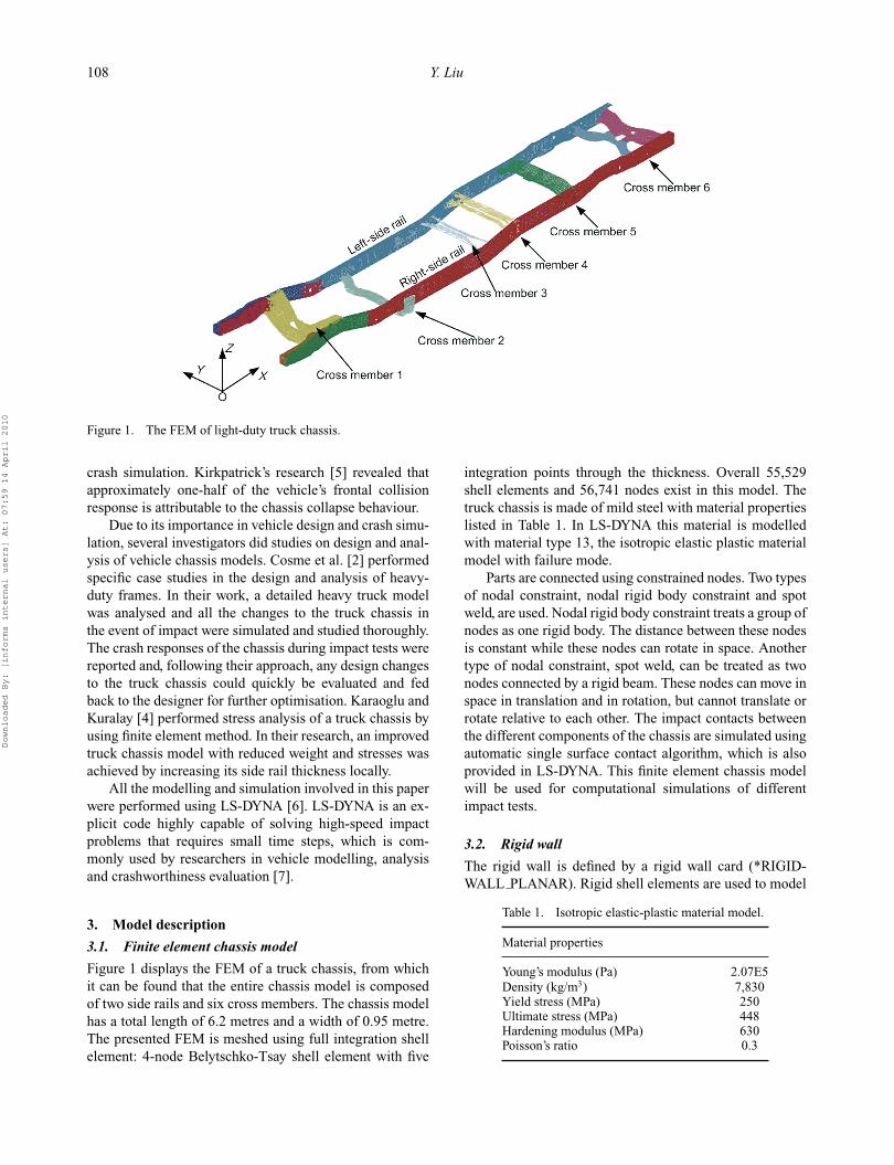
Figure 1. The FEM of light-duty truck chassis.
crash simulation. Kirkpatrick’s research [5] revealed thatapproximately one-half of the vehicle’s frontal collisionresponse is attributable to the chassis collapse behaviour.
Due to its importance in vehicle design and crash simu-lation, several investigators did studies on design and anal-ysis of vehicle chassis models. Cosme et al. [2] performedspecific case studies in the design and analysis of heavy-duty frames. In their work, a detailed heavy truck modelwas analysed and all the changes to the truck chassis inthe event of impact were simulated and studied thoroughly.The crash responses of the chassis during impact tests werereported and, following their approach, any design changesto the truck chassis could quickly be evaluated and fedback to the designer for further optimisation. Karaoglu andKuralay [4] performed stress analysis of a truck chassis byusing finite element method. In their research, an improvedtruck chassis model with reduced weight and stresses wasachieved by increasing its side rail thickness locally.
All the modelling and simulation involved in this paperwere performed using LS-DYNA [6]. LS-DYNA is an ex-plicit code highly capable of solving high-speed impactproblems that requires small time steps, which is com-monly used by researchers in vehicle modelling, analysisand crashworthiness evaluation [7].
3. Model description
3.1. Finite element chassis model
Figure 1 displays the FEM of a truck chassis, from whichit can be found that the entire chassis model is composedof two side rails and six cross members. The chassis modelhas a total length of 6.2 metres and a width of 0.95 metre.The presented FEM is meshed using full integration shellelement: 4-node Belytschko-Tsay shell element with five
integration points through the thickness. Overall 55,529shell elements and 56,741 nodes exist in this model. Thetruck chassis is made of mild steel with material propertieslisted in Table 1. In LS-DYNA this material is modelledwith material type 13, the isotropic elastic plastic materialmodel with failure mode.
Parts are connected using constrained nodes. Two typesof nodal constraint, nodal rigid body constraint and spotweld, are used. Nodal rigid body constraint treats a group ofnodes as one rigid body. The distance between these nodesis constant while these nodes can rotate in space. Anothertype of nodal constraint, spot weld, can be treated as twonodes connected by a rigid beam. These nodes can move inspace in translation and in rotation, but cannot translate orrotate relative to each other. The impact contacts betweenthe different components of the chassis are simulated usingautomatic single surface contact algorithm, which is alsoprovided in LS-DYNA. This finite element chassis modelwill be used for computational simulations of differentimpact tests.
3.2. Rigid wall
The rigid wall is defined by a rigid wall card (*RIGID-WALL PLANAR). Rigid shell elements are used to model
Table 1. Isotropic elastic-plastic material model.
Material properties
Young’s modulus (Pa) 2.07E5Density (kg/m3) 7,830Yield stress (MPa) 250Ultimate stress (MPa) 448Hardening modulus (MPa) 630Poisson’s ratio 0.3
Downloaded By: [informa internal users] At: 07:59 14 April 2010
International Journal of Crashworthiness 109
the wall, but which is only for visualisation purposes. Forthe full and offset frontal impacts with a rigid wall, slidinginterface is used to model the contact between the chassisand the wall. For the corner impact, the geometric con-tact entity option in LS-DYNA is employed, which pro-vides high accuracy and computational efficiency for metalforming problems.
4. Crash simulations
In this project, the truck chassis model is used for threetypes of crash simulation: full frontal impact, offset frontalimpact and corner impact. During these simulations, thechassis model impacts the rigid wall at an initial speed of15 m/s (≈33.8 mph) and the simulation time is set as 0.1 s(100 ms) for the frontal impacts and 0.24 s (240 ms) for thecorner impact. After computer analyses, accelerations aretaken at the centre of gravity of this model to estimate theresponses of truck chassis during different impact cases.Energy balance analyses are also performed in order toinvestigate the crash energy dissipation among differentchassis components during crashes. The performances oftruck chassis involved in impacts will then be discussed.The overall weight of this chassis is 236 kg and its centreof gravity location is measured at X = 3638.74 mm, Y =−2.54 mm and Z = 1674.23 mm, which are in a globalcoordinate system. The weight of each chassis componentis listed in Table 2. It should be noted that each of thesecomponents is composed of several parts.
4.1. Full frontal impact
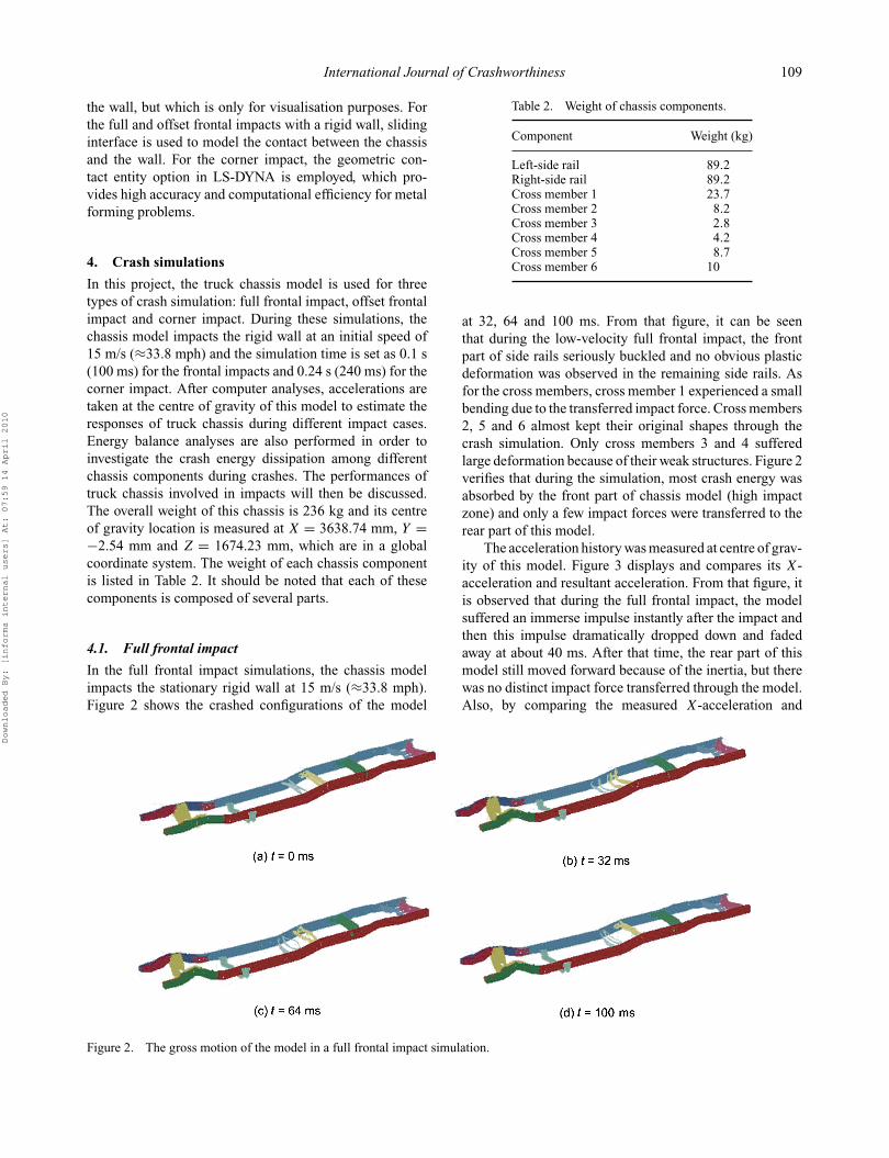
In the full frontal impact simulations, the chassis modelimpacts the stationary rigid wall at 15 m/s (≈33.8 mph).Figure 2 shows the crashed configurations of the model
Table 2. Weight of chassis components.
Component Weight (kg)
Left-side rail 89.2Right-side rail 89.2Cross member 1 23.7Cross member 2 8.2Cross member 3 2.8Cross member 4 4.2Cross member 5 8.7Cross member 6 10
at 32, 64 and 100 ms. From that figure, it can be seenthat during the low-velocity full frontal impact, the frontpart of side rails seriously buckled and no obvious plasticdeformation was observed in the remaining side rails. Asfor the cross members, cross member 1 experienced a smallbending due to the transferred impact force. Cross members2, 5 and 6 almost kept their original shapes through thecrash simulation. Only cross members 3 and 4 sufferedlarge deformation because of their weak structures. Figure 2verifies that during the simulation, most crash energy wasabsorbed by the front part of chassis model (high impactzone) and only a few impact forces were transferred to therear part of this model.
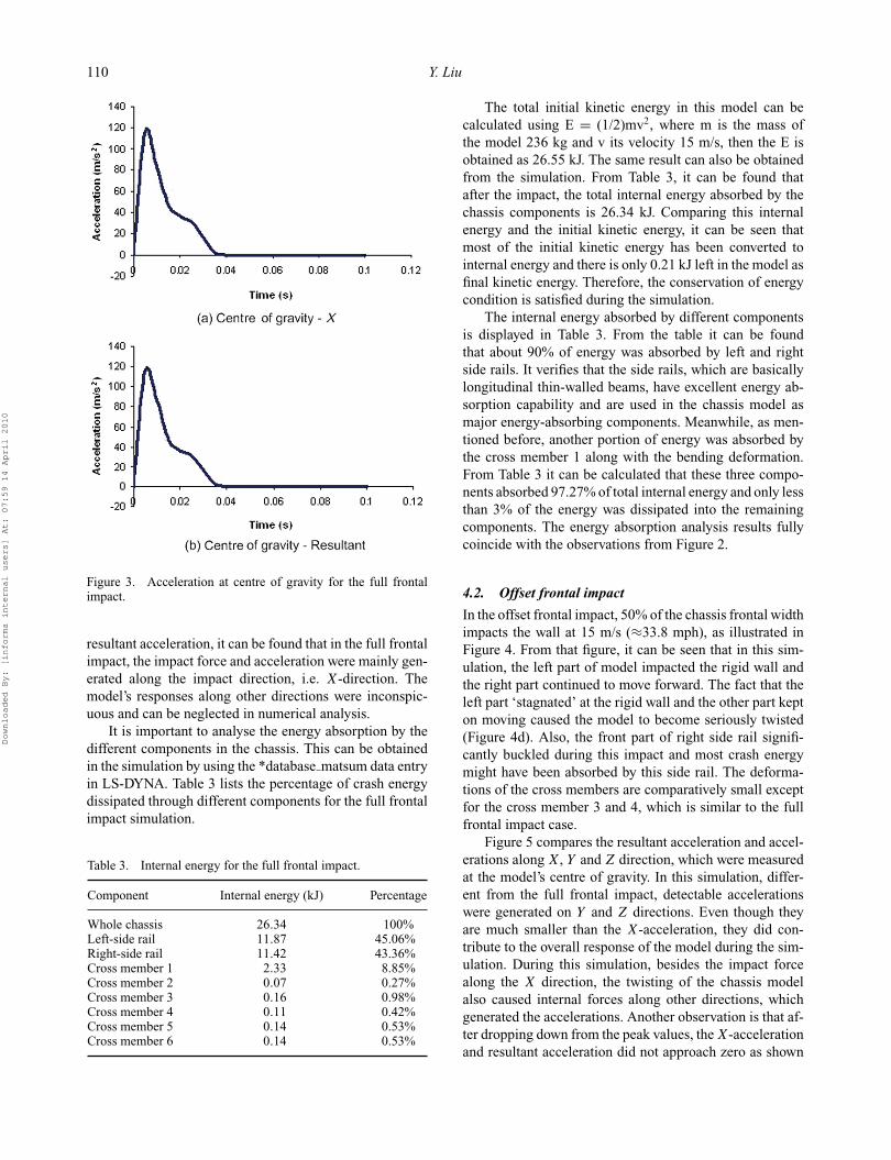
The acceleration history was measured at centre of grav-ity of this model. Figure 3 displays and compares its X-acceleration and resultant acceleration. From that figure, itis observed that during the full frontal impact, the modelsuffered an immerse impulse instantly after the impact andthen this impulse dramatically dropped down and fadedaway at about 40 ms. After that time, the rear part of thismodel still moved forward because of the inertia, but therewas no distinct impact force transferred through the model.Also, by comparing the measured X-acceleration and
Figure 2. The gross motion of the model in a full frontal impact simulation.
Downloaded By: [informa internal users] At: 07:59 14 April 2010
110 Y. Liu
Figure 3. Acceleration at centre of gravity for the full frontalimpact.
resultant acceleration, it can be found that in the full frontalimpact, the impact force and acceleration were mainly gen-erated along the impact direction, i.e. X-direction. Themodel’s responses along other directions were inconspic-uous and can be neglected in numerical analysis.
It is important to analyse the energy absorption by thedifferent components in the chassis. This can be obtainedin the simulation by using the *database matsum data entryin LS-DYNA. Table 3 lists the percentage of crash energydissipated through different components for the full frontalimpact simulation.
Table 3. Internal energy for the full frontal impact.
Component Internal energy (kJ) Percentage
Whole chassis 26.34 100%Left-side rail 11.87 45.06%Right-side rail 11.42 43.36%Cross member 1 2.33 8.85%Cross member 2 0.07 0.27%Cross member 3 0.16 0.98%Cross member 4 0.11 0.42%Cross member 5 0.14 0.53%Cross member 6 0.14 0.53%
The total initial kinetic energy in this model can becalculated using E = (1/2)mv2, where m is the mass ofthe model 236 kg and v its velocity 15 m/s, then the E isobtained as 26.55 kJ. The same result can also be obtainedfrom the simulation. From Table 3, it can be found thatafter the impact, the total internal energy absorbed by thechassis components is 26.34 kJ. Comparing this internalenergy and the initial kinetic energy, it can be seen thatmost of the initial kinetic energy has been converted tointernal energy and there is only 0.21 kJ left in the model asfinal kinetic energy. Therefore, the conservation of energycondition is satisfied during the simulation.
The internal energy absorbed by different componentsis displayed in Table 3. From the table it can be foundthat about 90% of energy was absorbed by left and rightside rails. It verifies that the side rails, which are basicallylongitudinal thin-walled beams, have excellent energy ab-sorption capability and are used in the chassis model asmajor energy-absorbing components. Meanwhile, as men-tioned before, another portion of energy was absorbed bythe cross member 1 along with the bending deformation.From Table 3 it can be calculated that these three compo-nents absorbed 97.27% of total internal energy and only lessthan 3% of the energy was dissipated into the remainingcomponents. The energy absorption analysis results fullycoincide with the observations from Figure 2.
4.2. Offset frontal impact
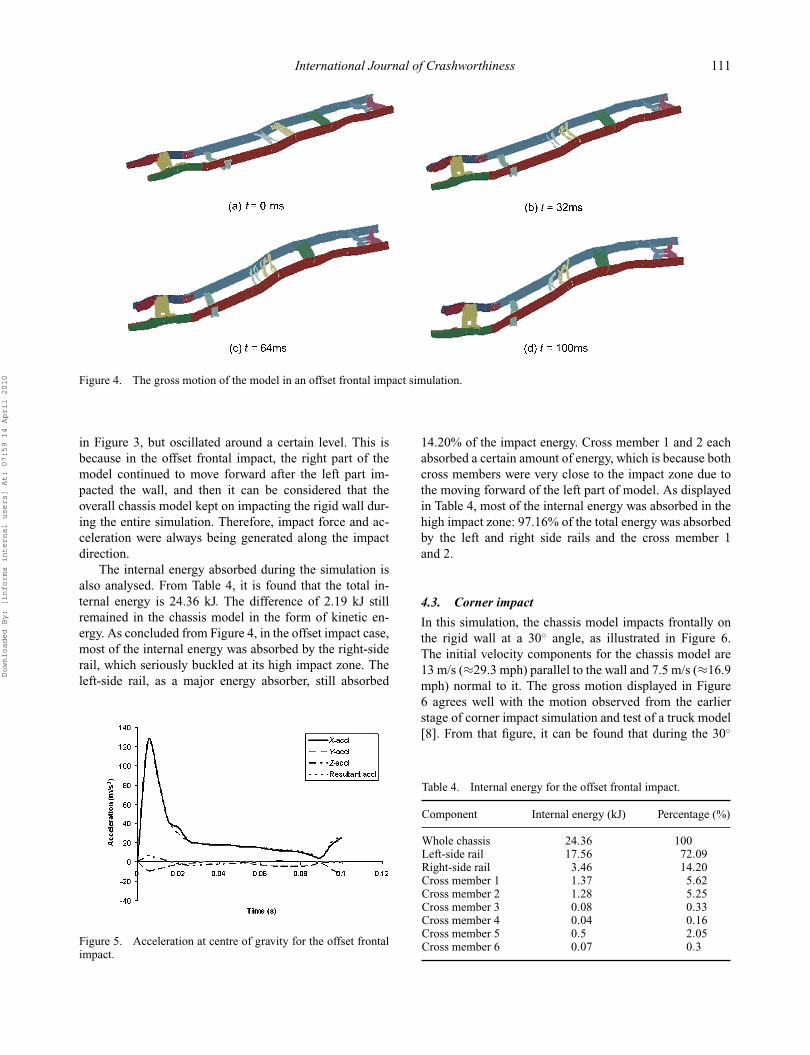
In the offset frontal impact, 50% of the chassis frontal widthimpacts the wall at 15 m/s (≈33.8 mph), as illustrated inFigure 4. From that figure, it can be seen that in this sim-ulation, the left part of model impacted the rigid wall andthe right part continued to move forward. The fact that theleft part ‘stagnated’ at the rigid wall and the other part kepton moving caused the model to become seriously twisted(Figure 4d). Also, the front part of right side rail signifi-cantly buckled during this impact and most crash energymight have been absorbed by this side rail. The deforma-tions of the cross members are comparatively small exceptfor the cross member 3 and 4, which is similar to the fullfrontal impact case.
Figure 5 compares the resultant acceleration and accel-erations along X, Y and Z direction, which were measuredat the model’s centre of gravity. In this simulation, differ-ent from the full frontal impact, detectable accelerationswere generated on Y and Z directions. Even though theyare much smaller than the X-acceleration, they did con-tribute to the overall response of the model during the sim-ulation. During this simulation, besides the impact forcealong the X direction, the twisting of the chassis modelalso caused internal forces along other directions, whichgenerated the accelerations. Another observation is that af-ter dropping down from the peak values, the X-accelerationand resultant acceleration did not approach zero as shown
Downloaded By: [informa internal users] At: 07:59 14 April 2010
International Journal of Crashworthiness 111
Figure 4. The gross motion of the model in an offset frontal impact simulation.
in Figure 3, but oscillated around a certain level. This isbecause in the offset frontal impact, the right part of themodel continued to move forward after the left part im-pacted the wall, and then it can be considered that theoverall chassis model kept on impacting the rigid wall dur-ing the entire simulation. Therefore, impact force and ac-celeration were always being generated along the impactdirection.
The internal energy absorbed during the simulation isalso analysed. From Table 4, it is found that the total in-ternal energy is 24.36 kJ. The difference of 2.19 kJ stillremained in the chassis model in the form of kinetic en-ergy. As concluded from Figure 4, in the offset impact case,most of the internal energy was absorbed by the right-siderail, which seriously buckled at its high impact zone. Theleft-side rail, as a major energy absorber, still absorbed
Figure 5. Acceleration at centre of gravity for the offset frontalimpact.
14.20% of the impact energy. Cross member 1 and 2 eachabsorbed a certain amount of energy, which is because bothcross members were very close to the impact zone due tothe moving forward of the left part of model. As displayedin Table 4, most of the internal energy was absorbed in thehigh impact zone: 97.16% of the total energy was absorbedby the left and right side rails and the cross member 1and 2.
4.3. Corner impact
In this simulation, the chassis model impacts frontally onthe rigid wall at a 30◦ angle, as illustrated in Figure 6.The initial velocity components for the chassis model are13 m/s (≈29.3 mph) parallel to the wall and 7.5 m/s (≈16.9mph) normal to it. The gross motion displayed in Figure6 agrees well with the motion observed from the earlierstage of corner impact simulation and test of a truck model[8]. From that figure, it can be found that during the 30◦
Table 4. Internal energy for the offset frontal impact.
Component Internal energy (kJ) Percentage (%)
Whole chassis 24.36 100Left-side rail 17.56 72.09Right-side rail 3.46 14.20Cross member 1 1.37 5.62Cross member 2 1.28 5.25Cross member 3 0.08 0.33Cross member 4 0.04 0.16Cross member 5 0.5 2.05Cross member 6 0.07 0.3
Downloaded By: [informa internal users] At: 07:59 14 April 2010
112 Y. Liu
Figure 6. The gross motion of the model in a corner impact simulation.
corner impact, most of the plastic deformation appeared onthe front part of left-side rail and the cross member 1 is theonly cross member that directly impacted the wall. If thechassis model is assembled with suspension systems, whichhave wheels and higher controllability, it will show the samemotion as an entire vehicle assembly during the cornerimpact simulation.
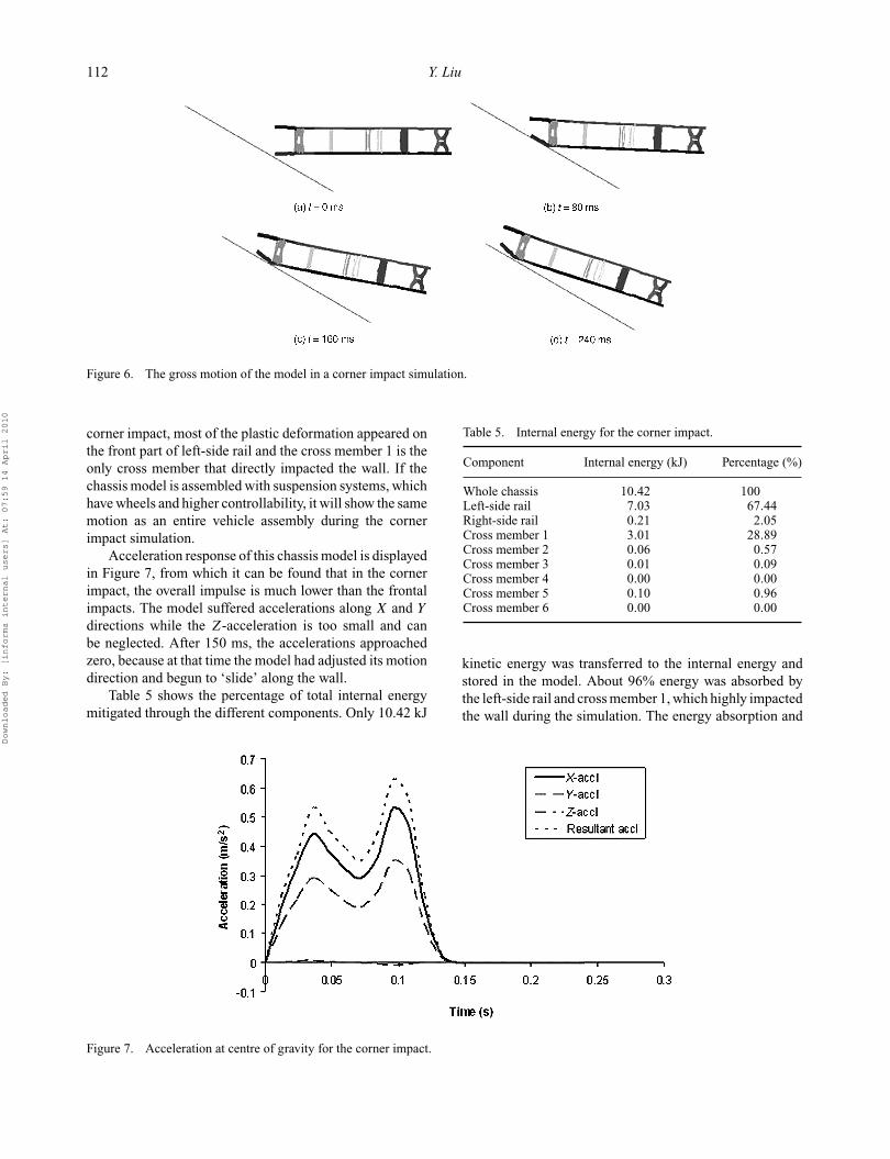
Acceleration response of this chassis model is displayedin Figure 7, from which it can be found that in the cornerimpact, the overall impulse is much lower than the frontalimpacts. The model suffered accelerations along X and Y
directions while the Z-acceleration is too small and canbe neglected. After 150 ms, the accelerations approachedzero, because at that time the model had adjusted its motiondirection and begun to ‘slide’ along the wall.
Table 5 shows the percentage of total internal energymitigated through the different components. Only 10.42 kJ
Table 5. Internal energy for the corner impact.
Component Internal energy (kJ) Percentage (%)
Whole chassis 10.42 100Left-side rail 7.03 67.44Right-side rail 0.21 2.05Cross member 1 3.01 28.89Cross member 2 0.06 0.57Cross member 3 0.01 0.09Cross member 4 0.00 0.00Cross member 5 0.10 0.96Cross member 6 0.00 0.00
kinetic energy was transferred to the internal energy andstored in the model. About 96% energy was absorbed bythe left-side rail and cross member 1, which highly impactedthe wall during the simulation. The energy absorption and
Figure 7. Acceleration at centre of gravity for the corner impact.
Downloaded By: [informa internal users] At: 07:59 14 April 2010

International Journal of Crashworthiness 113
distribution seems to be consistent with the gross motionillustrated in Figure 6.
5. Conclusions
This paper presents a detailed truck chassis model and usesthis model for crash simulations. The simulation resultscan correctly represent the model’s responses during realimpact tests. Through this project, the chassis model’s per-formances during full frontal, offset and corner impacts areinvestigated. Characteristics of different impact cases arerevealed and compared through acceleration and internalenergy analyses. From the paper, it is concluded that duringthe impact, the majority of impulse is generated along theimpact direction and most of the crash energy is absorbedby thin-walled beam members and other components in thehigh impact zone, which undergo the most serious plasticdeformation.
The presented chassis model is proved to be computa-tionally stable, reliable and repeatable through the simula-tions; therefore can be used in an entire vehicle model forthe crashworthiness analysis. Additional simulations alsoneed to be performed to evaluate the chassis response indifferent impact scenarios.
References[1] Z.Q. Cheng, J.G. Thacker, W.D. Pilkey, W.T. Hollowell,
S.W. Reagan, and E.M. Sieveka, Experiences in reverse-engineering of a finite element automobile crash model, Fi-nite Elem. Anal. Des. 37 (2001), pp. 843–860.
[2] C. Cosme, A. Ghasemi, and J. Gandevia, Application ofcomputer aided engineering in the design of heavy-dutytruck frames, SAE Transactions, Detroit, MI, USA, 1999-01-3760, 1999.
[3] J.M. Gonzalez, C.D. Kan, and N.E. Bedewi, Versatility andlimitations of a fully detailed finite element model of a 1997Dodge Grand Caravan for crashworthiness application,SAE Transactions, Detroit, MI, USA, 2000-01-0629, 2000.
[4] C. Karaoglu and N.S. Kuralay, Stress analysis of a truck chas-sis with riveted joints, Finite Elem. Anal. Des. 38 (2002),pp. 1115–1130.
[5] S.W. Kirkpatrick, Development and validation of high fi-delity vehicle crash simulation models, SAE Transactions,Detroit, MI, USA, 2000-01-0627, 2000.
[6] Livermore Software Technology Corporation, LS-DYNAKeyword User’s Manual, Livermore, CA, 1999.
[7] L. Mei and C.A. Thole, Data analysis for parallel car-crashsimulation results and model optimization, Simulat. Modell.Pract. Theory 16 (2008), pp. 329–337.
[8] A.K. Zaouk, N.E. Bedewi, C.D. Kan, and D. Marzougui, De-velopment and evaluation of a C-1500 pick-up truck modelfor roadside hardware impact simulation, Proceedings ofthe FHWA Simulation Conference, Langley, VA, 1996.
Downloaded By: [informa internal users] At: 07:59 14 April 2010