Developing Safety Critical Embedded Software under DO-178C
118
-
Upload
khangminh22 -
Category
Documents
-
view
1 -
download
0
Transcript of Developing Safety Critical Embedded Software under DO-178C


i
Developing Safety Critical Embedded Software under DO-178C
A Thesis submitted to the Graduate School
Of
The University of Cincinnati
In partial fulfillment of the requirements for the degree of
Master of Science
in the
Department of Electrical and Computer Engineering
of the
College of Engineering and Applied Sciences
November 2015
by
Yanyun WANG
Committee Chair: Dr. Carla Purdy

ii
ABSTRACT
Software installed on avionic equipment requires higher safety standards than any other
environment. DO-178C, Software Consideration in Airborne Systems and Equipment
Certification, proposed by Radio Technical Commission for Aeronautics (RTCA) and European
Organization of Civil Aviation Equipment (EUROCAE), deals with the safety of software used
in airborne systems. DO-178C was completed and approved by the RTCA in 2011 and replaces
DO-178B as the primary document for Transport Canada, EASA and FAA. DO-178C defines
the objectives and focuses on the procedures to produce software at a certain security / safety
level. The inclusion of object-oriented concept and formal methods in DO-178C allows great
flexibility of implementation. Most of the qualified software tools that can pass the certification
process outlined in DO-178C are from big companies such as Matlab, AdaCore and IBM. The
prohibitive price to enter the market makes it unaffordable for small business. The purpose of
this research is to identify suitable open source software that can fulfill the same mission with
minimal effort and cost while complying with the strict DO-178C standards.

iii

iv
Table of Contents
1. INTRODUCTION...................................................................................................- 1 -
2. AVIONIC SYSTEM DEVELOPMENT REGULATIONS ..........................................- 5 -
2.1 ARP4761 ................................................................................................................- 5 -
2.2 ARP4754 ................................................................................................................- 6 -
2.3 DO-254...................................................................................................................- 6 -
2.4 History of DO-178 Family ........................................................................................- 8 -
2.5 DO-178B ................................................................................................................- 9 -
2.6 DO-178C .............................................................................................................. - 12 -
3. SOFTWARE DEVELOPMENT FOR DO-178C COMPLIANCE ............................. - 17 -
3.1 Software Planning ................................................................................................. - 19 -
3.2 Software Requirements ......................................................................................... - 22 -
3.3 Software Design .................................................................................................... - 23 -
3.4 Software Implementation and Integration............................................................... - 23 -
3.5 Software Validation............................................................................................... - 24 -
3.6 Software Verification............................................................................................. - 24 -
3.7 Delivery................................................................................................................ - 24 -
4. TOOLS ................................................................................................................ - 26 -
4.1 Tool Qualification ................................................................................................. - 26 -
4.1.1 Development tool qualification ............................................................................... - 27 -
4.1.2 Verification tool qualification ................................................................................. - 28 -
4.2 Potential Open Source Tool Chains ........................................................................ - 29 -
4.2.1 Life-cycle management .......................................................................................... - 30 -
4.2.2 Requirements management.................................................................................... - 32 -
4.2.3 Software design and implementation ...................................................................... - 37 -
4.2.4 Software testing .................................................................................................... - 38 -
4.2.5 Traceability management ...................................................................................... - 39 -
4.2.6 Team management ................................................................................................ - 41 -
4.2.7 User management ................................................................................................. - 42 -
4.2.8 Version control ..................................................................................................... - 43 -
4.2.9 Release management ............................................................................................. - 44 -
4.2.10 OSEE for DO-178C compliance ............................................................................. - 45 -

v
4.2.11 TOPCASED ......................................................................................................... - 46 -
4.2.12 CPPCheck ............................................................................................................ - 51 -
5. CASE STUDY: BLACKBOX DECODER PROJECT .............................................. - 52 -
6. CONCLUSIONS AND FUTURE WORK ............................................................... - 73 -
References .......................................................................................................................... - 75 -
Appendix A. TUTORIAL ................................................................................................ - 80 -

vi
LIST OF FIGURES
Figure 1 Avionic System Development Regulations ......................................................................- 5 -
Figure 2 DO-178C Document Structure [34] .............................................................................. - 18 -
Figure 3 Action Tracking System [70] for OSEE........................................................................... - 31 -
Figure 4 Surgical Assistance Workstation (SAW) Architecture [71] ................................................ - 32 -
Figure 5 OSEE - Product Decomposition for SAW Project [71] ...................................................... - 33 -
Figure 6 OSEE - Artifacts [72] .................................................................................................. - 34 -
Figure 7 OSEE - Requirements [71] .......................................................................................... - 35 -
Figure 8 OSEE - Robot API Requirements in Word Format [71]..................................................... - 36 -
Figure 9 OSEE - TOPCASED Info Tracker [71] ............................................................................. - 37 -
Figure 10 OSEE – Test Management [71] .................................................................................. - 38 -
Figure 11 OSEE – Traceability [72] ........................................................................................... - 39 -
Figure 12 OSEE – Skywalker [71] ............................................................................................. - 40 -
Figure 13 OSEE - Team Management [71] ................................................................................. - 41 -
Figure 14 OSEE - User Management [71] .................................................................................. - 42 -
Figure 15 OSEE - Version Control [71] ...................................................................................... - 43 -
Figure 16 OSEE - Release Management [71] .............................................................................. - 44 -
Figure 17 Example Component Diagram [73] ............................................................................ - 47 -
Figure 18 Example UML File [73] ............................................................................................. - 48 -
Figure 19 UML Model Validation [73]....................................................................................... - 49 -
Figure 20 Generating Code from UML Model [73]...................................................................... - 50 -
Figure 21 CPPcheck Features [45]............................................................................................ - 51 -
Figure 22 Shift Negative Value Warning ................................................................................... - 51 -
Figure 23 Cleanflight Github Projects Overview [77]................................................................... - 52 -
Figure 24 BlackBox Decoder Internal Flow ................................................................................ - 53 -
Figure 25 Typical Header for Blackbox Log ................................................................................ - 55 -
Figure 26 BlackBox Decoder Data ............................................................................................ - 56 -
Figure 27 Case Study Diagram................................................................................................. - 57 -
Figure 28 Software Planning Process........................................................................................ - 61 -
Figure 29 High Level Requirements.......................................................................................... - 62 -
Figure 30 Low Level Requirements .......................................................................................... - 63 -
Figure 31 Software Verification and Testing .............................................................................. - 67 -
Figure 32 Branch Management ............................................................................................... - 68 -
Figure 33 Problem Reporting System ....................................................................................... - 68 -
Figure 34 Branch Change Report ............................................................................................. - 69 -
Figure 35 Version and Release Control ..................................................................................... - 70 -
Figure 36 Create Software Requirement................................................................................... - 83 -
Figure 37 Create High Level Requirement ................................................................................. - 85 -
Figure 38 Create a Team ........................................................................................................ - 86 -
Figure 39 Relate Requirements with Teams .............................................................................. - 87 -
Figure 40 Relate Users to Teams ............................................................................................. - 89 -
Figure 41 Create a Branch ...................................................................................................... - 90 -

vii
Figure 42 Import Requirement Documents ............................................................................... - 91 -
Figure 43 Requirement Search ................................................................................................ - 96 -
Figure 44 Create an Action ..................................................................................................... - 97 -
Figure 45 Action Details ......................................................................................................... - 98 -
Figure 46 Endorse ................................................................................................................. - 99 -
Figure 47 Analyze................................................................................................................ - 101 -
Figure 48 Create Decision Review.......................................................................................... - 102 -
Figure 49 Submit to Decision Review ..................................................................................... - 103 -
Figure 50 Decision Review Completed.................................................................................... - 104 -
Figure 51 Workflow List ....................................................................................................... - 109 -

viii
LIST OF TABLES
Table 1 DO-178 Family and Its History........................................................................................- 8 -
Table 2 Objectives for 5 Design Assurance Level (DAL) [3] ........................................................... - 10 -
Table 3 Tool Qualification ...................................................................................................... - 14 -
Table 4 Memory Management................................................................................................ - 14 -
Table 5 Formal Methods ........................................................................................................ - 14 -
Table 6 Model Based Design & Object Oriented Technology........................................................ - 15 -
Table 7 Normal Range Tests and Robustness Tests..................................................................... - 66 -

- 1 -
1. INTRODUCTION
Software controlled equipment and systems are gradually being integrated into military and civil
avionic systems. As can be expected, accidents due to software flaws or crashes are increasing
accordingly. In June 1994, A Chinook helicopter of the UK’s Royal Air Force crashed into the
Mull of Kintyre [1] due to a software defect in the aircraft’s engine control module. In April
1992, an F-22 Raptor landed with a non-fatal crash at Edwards Air Force Base in California [2].
This was caused by a software bug which didn’t handle the pilot-induced oscillation correctly.
Subsequently, a document dealing with software considerations in airborne systems and
equipment certification was developed jointly by the United States and Europe. The document,
DO (DOcument) -178B [3], was published in December 1992 and upgraded to DO-178C [4] in
December 2011.
There is no statistical evidence about the efficacy of DO-178 available to the public. However,
surprisingly, there are now 22,000 certified jet airplanes in service throughout the whole world
[5], but there have been no airplane crashes in passenger service reportedly due to software
failure since December 1992. This inspiring result encourages the industry to keep evolving the
DO-178 standard. Meanwhile, the demand for software providing solutions for DO-178
compliance is surging. Matlab and IBM have their own Commercial Off The Shelf (COTS) [6]
software available targeting this promising market [7] [8]. Due to the complexity and the
strictness of the requirement, it’s prohibitive to enter this market. But the development
ecosystem is incomplete without the contribution of small business. On the other hand, open
source software is abundant but not organized. Typically, open source software targets a small
problem without considering the big picture.
- 2 -
Thus, there is a need to organize the existing open source tools and provide a one stop solution
for developing DO-178 compliant embedded software. Use of such tools in an educational
setting will also enhance the skills of students who aspire to careers in developing avionic and
other safety-critical software.
Let’s think about how to certify a bottle of water. The proper procedure should be to obtain a
small sample of water, take it to the official inspection bureau, and check for any harmful content.
The manufacturing process is completely inside a black box to the inspector. But what about
software? Since it’s not plausible to sample it bit by bit, the software instead should be
considered and verified as a complete piece. Developers create test cases and examine the output
and hope they can prove the absence of bugs. But the avionic software industry is so safety
critical that the limited number of test cases is not enough to prove software correctness and
sturdiness.
Any software, even a tiny program with only a few lines of code, can have almost infinite
running time state due to its complex internal structure and possible variable value space. Any
hole or back door deeply hidden in the software can be lethal. Only by checking how the
software is actually created can we keep malicious activities and potential potholes away and
gain enough confidence to deliver the product. Certification equals demonstrating reliability.
Therefore, safety critical software products need certification and it should be de livered by a
certification authority. For avionic software, DO-178 provides a guideline about what
certification is and how to certify software components.

- 3 -
There have been a number of projects aiming at providing open source tools for developing DO-
178 compliant software. These include:
- Open Source Requires Management Tool (OSRMT)/aNimble Platform [9].
OSRMT is designed with full Software Development Life Cycle (SDLC) traceability for
software requirements, design, implementation, verification and validation. It provides the
functionality of managing requirement attributes, version control and derivation. After its last
update in 2007 it was upgraded to the brand new aNimble Platform. The architecture
changed and became entirely web based.
- Unified Modeling Language (UML, implemented in Eclipse) [10]
UML is a generic modeling language that provides a way to visualize the design. It was
developed in 1994-95 and published by the International Organization for Standardization
(ISO) as an approved ISO standard.
The OSRMT/aNimble is not powerful enough with its lightweight web based structure. It doesn’t
provide full fledged documentation of the software structure and usage either. UML is popular in
the engineering world, but it’s not designed for DO-178 compliance. There are other better
UML-based software products available that are tailored to provide better documentation and
traceability.
In this thesis, we have identified an open source tool chain specifically targeting DO-178
compliant software development.

- 4 -
This thesis is organized as follows. Chapter 2 describes the effective components for the DO-178
family and its history. Chapter 3 illustrates how to break down software development into DO-
178 compliant steps. Chapter 4 identifies possible freeware tool chains to develop embedded
software that meets the DO-178 standard, and walks through the detailed implementation for
each tool with real life examples. Chapter 5 is a case study of using open source tool
combinations to develop a safety level D software component, the Blackbox Decoder, under the
strict DO-178C regulation. Chapter 6 helps users to learn how to deploy and use these open
source tools. Chapter 7 summarizes conclusions and discusses possibilities for future work.

- 5 -
2. AVIONIC SYSTEM DEVELOPMENT REGULATIONS
Let’s look at the basic work flow for embedded system development.
Figure 1 Avionic System Development Regul ations
As shown in Figure 1, it’s divided into 4 portions and regulated by 4 FAA standards. We will
talk about each portion in detail in this chapter.
2.1 ARP4761
ARP stands for The Aerospace Recommended Practice (ARP), a standard, or a practice
recommended by the Society of Automotive Engineers (SAE). ARP4761 is the “Guidelines and
Methods for Conducting the Safety Assessment Process on Civil Airborne Systems and
Equipment” [11]. It recommends a process to assess the safety of an avionic system by using
statistical modeling techniques. Here is the general flow of ARP4761:
Perform the aircraft level Functional Hazard Assessment [12] together with aircraft level
requirements development.
- 6 -
Perform the system level Functional Hazard Assessment together with aircraft functions
to system functions allocation, and the Common Cause Analysis Initiation.
Perform the Preliminary Safety System Analysis together with system architecture
development, and Common Cause Analysis update.
Iterate the Common Cause Analysis and Preliminary Safety System Analysis as the
system is divided as hardware and software components.
Perform the System Safety Assessment together with system implementation, and
complete the Common Cause Analysis.
The results go to the certification process.
2.2 ARP4754
ARP4754A, released in December 2010, is the “Guidelines For Development Of Civil Aircraft
and Systems” [13]. It deals with the whole life-cycle of aircraft system development for DO-178
certification.
The system includes both software and hardware, which require support for each category from
other aviation standards, which are DO-178C for software and DO-254 for hardware [14].
2.3 DO-254
DO-254 “Design Assurance Guidance For Airborne Electronic Hardware” [15] , as explained by
its name, assures the reliability of hardware design for avionic systems development. The
following processes can be adopted to achieve compliance with the DO-254 System Aspect of
Hardware Design Assurance [16]

- 7 -
Top-Level Drawings
Hardware Verification P lan (HVP)
Plan for Hardware Aspects of Certification (PHAC)
Hardware Accomplishment Summary (HAS)
Hardware Design Life Cycle [17]
Planning
Requirement Capture
Conceptual Design
Detailed Design
Implementation & Product Transition

- 8 -
2.4 History of DO-178 Family
Table 1 DO-178 Family and Its History
Table 1 shows the evolution of the DO-178 family. Everything starts from MIL-STD-498
“Military Standard Software Development and Documentation” [18] and DOD-STD-2167A
“Military Standard Defense System Software Development” [19]. Based on these military
standards, the commercial aircraft oriented DO-178 [20] came out between 1980 and 1982 and
focused on artifacts, documentation, traceability and testing. These elements composed the
backbone of today’s guidelines. Three years later, DO-178A added the four criticality levels
which become the Design Assurance Level (DAL) [21]. It also suggested the use of the waterfall
methodology, which connects to many modern software development methodologies. DO-178B
is an overhaul of the previous guideline. It still represents the main body of guidelines for
avionic software system development. DO-178C added a handful of changes to incorporate
emerging new methods or techniques such as formal methods [22]. We will discuss the details of
DO-178B and DO-178C in the following sections.

- 9 -
2.5 DO-178B
DO-178B deals with the “Software Considerations in Airborne Systems and Equipment
Certification”. Radio Technical Commission for Aeronautics (RTCA) [23] in the United States
published DO-178B and European Organization of Civil Aviation Equipment (EUROCAE) [24]
in Europe published the corresponding ED-12B [25]. The Federal Aviation Administration (FAA)
certifies the software that performs reliably in an airborne system under the guidance of DO-
178B. In this paper, we will focus on relevant regulations in the United States.
Before proceeding with DO-178B, a Design Assurance Level (DAL) needs to be determined by
the safety assessment and hazard analysis process. Here is the definition from ARP4761:
“A: Catastrophic – Failure may cause a crash. Error or loss of critical function required to
safely fly and land aircraft.
B: Hazardous – Failure has a large negative impact on safety or performance, or reduces the
ability of the crew to operate the aircraft due to physical distress or a higher workload, or
causes serious or fatal injuries among the passengers.
C: Major – Failure is significant, but has a lesser impact than a Hazardous failure (for example,
leads to passenger discomfort rather than injuries) or significant ly increases crew workload
D: Minor – Failure is noticeable, but has a lesser impact than a Major failure (for example,
causing passenger inconvenience or a routine flight plan change)
E: No Effect – Failure has no impact on safety, aircraft operation, or crew workload. “ [11]
Since these are all qualitative measurements, here we list some assurance levels for some
common system components for reference [26]:

- 10 -
Level A: Engine Controls
Level B: Navigation and Communication Radios
Level C: Pressure Control System
Level D: Maintenance System, Transponders
Level E: Entertainment System, Satellite Phone
The software safety cannot be guaranteed by DO-178B itself. Additional system safety analysis
tasks and objectives need to be addressed and accomplished accordingly. The certification
authorities and the DO-178 documents specify the correct DAL to be established using the
comprehensive analysis methods to establish the software levels A-E. Consequently, ARP-4761
is adopted and software safety analysis tasks are accomplished in sequential steps [27].
ARP-4761 Criticality DO-178 DAL DO-178 Objectives Catastrophic A 66
Hazardous B 65
Major C 57
Minor D 28
No effect E NA Table 2 Objectives for 5 De sign A ssurance Level (DAL) [3]
Table 2 shows that the more critical the embedded software is, the higher the DAL level is, and
the more objectives are imposed on the development process. These objectives and software
safety tasks are indispensable components in hazard analysis and DAL determination. FAA, the
certifying authority and DO-178B specifically declare that the corresponding DAL level should
be targeted and software Levels A-E should be established. With regard to certain objectives, the
verification and validation team should be independent from the software development team.
Here is a list of coverage required at Levels A, B and C [28]:
Level A:
Coverage at machine code level: directly verify the machine code

- 11 -
Or traceability from source code to object code : being able to trace from each source
code statement to the object code, need to identify the 1 to 1 relationship
Or use different compilers/different language: design the whole system with two
independent teams using different languages and compare the output
MCDC testing: Modified Condition/Decision Coverage, “each entry and exit point is
invoked; each decision takes every possible outcome; each condition in a decision takes
every possible output; each condition in a decision is shown to independently affect the
outcome of the decision” [29]
Level B:
Statement Coverage: A white box test method makes sure each line of code in the test is
executed at least once.
Decision Coverage: A white box test method makes sure each branch of each decision point is
executed at least once.
Level C:
Statement Coverage: Same as the above description.
Decision Coverage: Not required for this level.
- 12 -
2.6 DO-178C
DO-178C is the primary document after DO-178B and the basis on which the federal
transportation authority approves all current software avionic systems. DO-178C is broken down
into seven subgroups by the joint committee of RTCA/EUROCAE [30]:
SG1 SC-205 / WG-71 (SCWG) Document Integration
SG2 Issues and Rationale
SG3 Tool Qualification
SG4 Model Based Development (MBD) and Verification
SG5 Object-Oriented Technology
SG6 Formal Methods (FM)
SG7 Safety Related Considerations
DO-178C has done the following to improve DO-178B:
a. DO-178C corrects inconsistencies and known issues, e.g. DO-178C corrected the
definition of Source Code as follows:
“This data consists of code written in source language(s). The Source Code is used with
the compiling, linking, and loading data in the integration process to develop the
integrated system or equipment. For each Source Code component, this data should
include the software identification, including the name and date of revision and/or
version, as applicable” [30]
For comparison, here is the source code definition in DO-178B:

- 13 -
“This data consists of code written in source language(s) and the compiler instructions for
generating the object code from the Source Code, and linking and loading data. This data
should include the software identification, including the name and date of revision and/or
version, as applicable.” [3]
b. DO-178C clarifies inconsistent terminologies:
e.g., not only are “Guidance” and “Guidelines” used inconsistently throughout DO-178B,
but their real meanings were also confusing. The committee prefers to use “Guidance”
due to the fact that “Guidance” expresses a stronger sense of obligation than “Guidelines”.
Therefore, all the recommendations are termed “Guidance” and all the information
oriented texts are termed “Supporting information”.
c. DO-178C clarifies unclear descriptions of DO-178B:
e.g., during the development of DO-178B, the system level guidance is not developed yet.
As a result, Chapter 2 of DO-178B was written to address all potential system aspects.
DO-178C made significant changes in Chapter 2 to incorporate the text from ARP4754,
the system development guidelines.
d. The committee intends to keep the core document as much as possible independent of
any methods or techniques. Therefore these new methods and techniques are covered in
four supplement documents:
Tool Supplement, DO-330
Model Based Design (MBD) Supplement, DO-331

- 14 -
Object Oriented (OO) Supplement, DO-332
Formal Method (FM) Supplement, DO-333
Comparisons are made between DO-178B and DO-178C based on categories defined by each
supplement [31]. We summarize them in the four tables below (tables 3-6):
Table 3 Tool Qualification
Table 4 Memory Management
Table 5 Formal Methods

- 15 -
Table 6 Model Based De sign & Object Oriented Technology
Since the RTCA officially replaced DO-178B by DO-178C on 2011, this paper will focus on
DO-178C and its compatible software.
There is one more thing worth mentioning before we finish this chapter. Even if we follow the
well established DO-178C, it’s still possible for us to develop a malfunctioning system. DO-
178C only defines what you need to do. It leaves the question of how to do it to project managers
and developers. In other words, DO-178C makes sure you stick to your plan strictly and you
don’t skip any of the steps. However, DO-178C cannot tell you how to write the plan.

- 16 -
Developing all aspects of a solid plan requires in-depth knowledge of modern software
development methodologies, as summarized, for example in Chapter 1, especially page 13-16 of
Object-Oriented Software Engineering [32] and in Part 1 (The Software Process) of Software
Engineering: A Practitioner’s Approach [33].
In our BlackBox Decoder (BBD) project, we adopt the water fall model to make sure the
software from top to bottom is well defined and aligned. We will talk about the water fall model
more below.

- 17 -
3. SOFTWARE DEVELOPMENT FOR DO-178C COMPLIANCE
A typical software development cycle can be broken down into the following steps:
Software Planning: defines what needs to be done under system requirements and DO-
178C
Software Development: there are 3 sub-steps here:
o Requirements: defines software functionality, interface and other specifications
o Design: defines software architecture and decomposition into blocks
o Implementation: implement what’s defined in the previous steps
o Integration: load the object code to the host hardware
Software Verification: according to the specification documents verify the software
product to make sure it fulfills the defined functionality
Software Configuration Management: handles and archive all the changes, bug fixes and
revision control
Software Quality Assurance (verification and validation): reviews and analyzes all the
output documents from previous steps and make sure all the objectives are fulfilled
Certification Liaison: Designated Engineering Representative works with the developer
company to coordinate the certification process
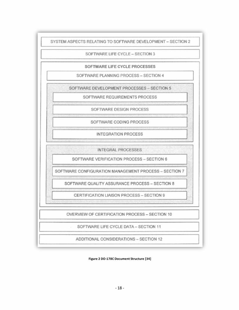
DO-178C has clear guidance for each aspect of the software development process. Let’s take a
look at the DO-178C document structure which provides this guidance (Figure 2):
- 18 -
Figure 2 DO-178C Document Structure [34]

- 19 -
DO-178C consists of 12 sections, 2 annexes and 3 appendices. Figure 2 shows the 12 sections.
Annexes and appendices are not shown in Figure 2. Sections 2 and 10 talk about the overall
certification processes for the software and hardware within the system. Sections 3, 4 and 5, as
clearly demonstrated in Figure 2, deal with the guidelines during the software life cycle, planning
and development. Sections 6-9 support the requirements of Section 3-5. Section 11 provides
detailed data for the software life cycle and section 12 adds additional considerations. Annex A
is the objectives for each safety level. Annex B is the document glossary. Appendices A, B, C
and D include additional information, including a process improvement form, a list of
contributors and an index. The detailed requirements for each phase are described below.
3.1 Software Planning
Starting the DO-178C software development lifecycle, the developer should address the
objective of the project planning:
INPUT: System requirement description written by the project manager
OUTPUT: Software Development Plan (SDP), Plan for Software Aspects of Certification
(PSAC), Software Quality Assurance Plan (SQAP), Software Configuration Management P lan
(SCMP), Software Verification Plan (SVP) and Software Requirements, Design & Coding
Standards (SRDCS) documents.
A breakdown of the output documents is given below: [35]
PSAC: Plan for Software Aspects of Certification (DO-178B Section 11.1), used to determine
whether the software life cycle complies with the correspondent DAL level the software is
targeting. It should at least include:

- 20 -
System Overview
Software Overview
Certification Considerations
Software Life Cycle
Software Life Cycle Data
Schedule
Additional Considerations
SQAP: Software Quality Assurance Plan (DO-178B Section 11.5). SQAP oversees the entire
DO-178C process and demands a prudent independence at all levels. Any deviations from plans
during the development process, determined by SQAP, should be identified, documented,
assessed, traced and resolved. SQAP works with SCMP to make sure the proper control is in
place, being responsible for assuring the product delivered matches the specification and design
plan. SQAP should at least include:
Environment
Authority
Activities
Transition Criteria
SQA Records
Supplier Control
SCMP: Software Configuration Management Plan (DO-178B Section 11.4). SCMP analyzes and
supervises important software changes to ensure the proper implementation, and meanwhile

- 21 -
related personnel or clients are kept up to date. It describes what methods to use to achieve the
software configuration management process objectives defined in DO-178B Section 11.4. SCMP
should at least include:
Environment
Activities
Configuration Identification
Baselines and Traceability
Problem Reporting
Change Control
Change Review
Configuration Status Accounting
Archive, Retrieval, and Release
Software Load Control
Software Life Cycle Environment Control
Software Life Cycle Data Controls
Transition Criteria
SCM Data
Supplier Control
SWDP: Software Development Plan (DO-178B Section 11.2), identifies what software life-cycle,
standards and objectives to adopt in the software development process. SWDP could be part of
PSAC. SWDP should at least include:
Standards

- 22 -
Software Life Cycle
Software Development Environment
SWVP: Software Verification Plan (DO-178B Section 11.3), establishes the verification
procedures, accounting for two thirds of the objectives in DO-178C. The SVP should at least
include:
Organization
Independence
Verification Methods
Verification Environment
Transition Criteria
Partitioning Considerations
Compiler Assumptions
Re-verification Guidelines
Previously Developed Software
Multiple-Version Dissimilar Software.
3.2 Software Requirements
INPUT: output from the software planning phase, including:
System Requirements Data (SRD) allocated to software
Hardware Interfaces and System Architecture
Software Development Plan
Software Requirements, Design, and Coding Standards (SRDCS)

- 23 -
OUTPUT: high level requirements including functional, performance, interface and safety-
related requirements.
Software High Level Requirements Document (SHLRD)
Software High Level Signal Dictionary (SHLSD)
3.3 Software Design
INPUT: outputs of the software requirement phase, including:
Software High Level Requirements Document (SHLRD)
Software High Level Signal Dictionary (SHLSD)
Software Development Plan
Software Requirements, Design, and Coding Standards (SRDCS)
OUTPUT: low level requirements include design and architecture details , including
Software Low Level Requirements Document (SLLRD)
Software Low Level Signal Dictionary (SLLDD)
3.4 Software Implementation and Integration
INPUT: outputs of software design phase, including:
Software Low Level Requirements Document (SLLRD)
Software Low Level Data Dictionary (SLLDD)
Software Development Plan
Software Requirements, Design, and Coding Standards (SRDCS)
OUTPUT:
Source Code

- 24 -
Executable Object Code
3.5 Software Validation
Assures the high level requirements match the system requirements
Assures the low level requirements match the high level requirements
Assures the code implementation and integration match the low level requirements
3.6 Software Verification
Assures the executable object code is aligned with and verified against high level and low
level requirements
Software Verification P lan (SVP): describes how test procedures are developed and
reviewed
Software Verification Cases & Procedures Document (SVCP): describes how to
reproduce the test, and includes a trace matrix for test coverage based on requirements
Structural coverage analysis: includes Statement Coverage, Decision Coverage and
Modified Condition/Decision Coverage (MC/DC)
Source code to object code trace analysis (Level A only): assures all the assembly code
generated by the compiler can be traced back to the source code
3.7 Delivery
Before the final submission of the project data maintained by the configuration management
system, the following documents are required to be ready:

- 25 -
Software Configuration Index (SCI)
Software Environment Configuration Index (SECI)
Software Accomplishment Summary (SAS)

- 26 -
4. TOOLS
4.1 Tool Qualification
DO-178C acknowledges the need for tools; however, tools need to demonstrate their
dependability. The purpose of tool qualification is to make sure the tool can be trusted and the
results generated by the tools can be certified together with other software components. DO-
178C requires all the tools to be qualified for that specific project, defined by the project’s
requirements and development practices. DO-178C categorizes the tools into two types [36]:
Software development tool: “tools whose output is part of airborne software and thus can
introduce errors.” [37]
Software verification tool: "tools that cannot introduce errors, but may fail to detect
them." [37]
For example a compiler will take in the high level software code and generate executable binary
code for subsequent steps. Therefore the compiler is a development tool. A verification tool
could be a simulator, test execution tool, coverage tool, reporting tool, etc.
Certification and qualification are different by definition. Certification applies to the safety
critical software product, while qualification applies to the tools used during the certification
process. Testing and verification tools are widely adopted in DO-178C projects. None of these
testing and verification tools are required to be certified. Instead, any code that goes into a DO-
178C application must be DO-178C certifiable.

- 27 -
4.1.1 Development tool qualification
According to DO-178C, if the development tool needs to be qualified, the developer needs to
submit the Tool Operational Requirement (TOR), including the tool installation, functionality,
environment, operational manual, development and expected responses. Several important
documents need to be submitted for approval, including a Tool Qualification P lan, Tool
Configuration Management Records, a Tool Configuration Management Index, Tool
Development Data, Tool Verification Records, Tool Quality Assurance Records, a Tool
Accomplishment Summary, etc. [38]. The developer must show and prove the TOR is correct,
consistent and complete.
If all the tools, including the operating system, tools like Microsoft Office, and compilers need to
be qualified in the strictest way as described above, it is unreasonable, and impossible for anyone
to develop the software in accordance with DO-178C. Therefore, the “Checker Mechanism” is
allowed by DO-178C as an alternative way to qualify software. Take Microsoft Excel as an
example. The qualification process can be skipped if the data stored can be exported in a simple
format that can be easily compared with the master file and the modification item list and
reviewed by the Designated Engineering Representative (DER). This workaround is widely
accepted by industry and allowed by the authority (RTCA/EUROCAE) and therefore
recommended for all the possible software in this paper.

- 28 -
4.1.2 Verification tool qualification
In the DO-178C processes, software tools may be used to help and expedite the system
development process. The certification process should include all the tools used.
Development tools have the same requirements as the embedded code. They must have been
developed following the DO-178C process.
Verification tools qualification is a much simpler process which demonstrates that the tool
fulfills its requirements under normal operational conditions. DO -178C requires an extensive
black box testing of the tools such as decision table testing, all-pairs testing, state transition
tables testing, equivalence partitioning testing, and boundary value analysis testing.
DO-178C specifies the following tool qualification steps:
Prepare a tool qualification plan for the DER
Prepare the tool operational requirements
Demonstrate that the tool aligns with tool operational requirements, and then summarize
the limitations and restrictions of the tool.
Present the tool qualification results to DER

- 29 -
4.2 Potential Open Source Tool Chains
Due to the fact that DO-178C is objective oriented, great flexibility is allowed in the software
development process. Nothing is defined other than abstract requirements. Therefore it’s very
hard to implement for the first time and there are only a limited number of prohibitively
expensive software products from large companies in the market. Our research aims to achieve
the same functionalities provided by these expensive commercial software tools with high
reliability through open source software. A large number of open source software tools are
available online and the following combinations are found to be acceptable as explained below:
Life cycle management: Open System Engineering Environment (OSEE) 0.13.0 for Eclipse [39]
Requirement management: rmtoo [40], OSRMT/aNimble [9], OSEE, TOPCASED [41]
Software development tools: UML2 on Eclipse [10], TOPCASED, gcc [42]
Software verification tools: gdb [43], Adacontrol [44]
Static Analysis: CPPCheck(win) [45], oink [46], CQUAL [47]
Dynamic Analysis: Cheddar [48], GNATmem [49], Qemu [50], Dev-C++ [51]
Testing: FitNesse [52], cfix [53], Check [54], CppTest [55],cu [56]
Build infrastructure: GNU Make [57], Dev-C++ [51]
Configuration management: CVS [58], Subversion [59]
Traceability management: OSEE
In this work we have chosen to use OSEE for life cycle management, requirement management
and traceability management, TOPCASED for software development (especially for UML model
development), CPPCheck for static analysis, CppTest for unit testing, Dev-C++ for compilation
and dynamic analysis , and CVS for configuration management.

- 30 -
4.2.1 Life-cycle management
Life-cycle management encompasses requirements management, software architecture, computer
programming, software testing, software maintenance, change management, project management,
and release management [60]. The industry has defined 6 processes to fulfill these tasks:
Analysis, Design, Implementation, Testing, Documentation and Execution. Meanwhile, a
number of models are introduced to organize the above 6 processes, including the waterfall
model, spiral model, iterative and incremental development model, agile development model,
rapid application development model and code and fix model [61].
The waterfall model [62] emphasizes finishing one phase before proceeding to the next one,
which is the backbone for most of the software development projects. The spiral model [63]
passes through some number of iterations of all the phases and places great emphasis on
deliberate iterative risk analysis, which is well accepted in large scale complex system design.
The iterative and incremental development model [64] constructs the initially small but ever
growing software project which addresses important issues at the early development stage and is
great for prototype development for demonstrations. The agile development model [65] adopts
iterative development as a basis but advocates continuous people feedback in the later phases,
which is also good for prototype development. The rapid application development model [66]
interleaves planning with implementation and allows fast development. The code and fix
(“cowboy coding” [67]) model is not a deliberate strategy, since the code is written with little or
no design. In our research, we look carefully at the Open System Engineering Environment
(OSEE [39]) platform which supports all the 6 models. Its powerful Action Tracking System

- 31 -
(ATS) makes end to end traceability possible. It successfully satisfies all the project management
requirements and fits into the well accepted industrial models.
The OSEE is an open platform based on eclipse [68] which offers a highly integrated tool
environment supporting lean principle [69] over the product life cycle. The lean principle here
means use least resource while creating most value for customers. The user defined data model
in OSEE provides a convenient way to store all the project data, which makes revision control,
traceability, status reporting and project metrics management a lot easier. The branch
management ability, including project branching and merging and report generation, gives great
control power to the user. Since a complete revision of project history is well recorded by OSEE,
the project manager can go through the changes and make revisions easily.
Figure 3 Action Tracking System [70] for OSEE

- 32 -
The Action Tracking System (ATS) of OSEE, as shown in Figure 3, records every step
throughout the project. For each action, the action details, the action type, the assignees, the
action date, the target version and team members are logged. In our example, the change of
workflow needs to go through endorse, analyze, authorize, implement, completed or canceled
states. Each review needs to go through prepare, review, meeting or canceled states. Each task
needs to go through work, completed or canceled states. The Action Tracking System (ATS)
makes sure every tiny modification of requirements, workflow, and documentation is on record.
4.2.2 Requirements management
There is one thing we need to do before requirement management, the product analysis. The
Surgical Assistance Workstation (SAW [71]) is a good exemplary case with detailed
documentation and is open to the public.
Figure 4 Surgical Assistance Workstation (SAW) Architecture [71]
Figure 4 shows a typical SAW system from Intuitive Surgical Inc. It extends the human ability to
perform those tasks what were considered impossible before. SAW offers a much steadier hand
for eye microsurgeries. SAW also can go through throat and upper airways to perform minimally
invasive surgeries. With SAW, hip augmentation surgeries can be done with consistent force and

- 33 -
much better accuracy. In order to assist in these areas, certain components are indispensible for
SAW.
Figure 5 OSEE - Product Decomposition for SAW Project [71]
In Figure 5, we break down the core SAW system to components such as chasis, cognitive
decision aiding, communications, controls, data management, electrical, hydraulics, navigat ion,
propulsion, robot API, robot survivability equipment, robot systems management and some
unknown and unspecified parts.

- 34 -
Figure 6 OSEE - Artifacts [72]
Requirement management documents, analyzes, traces, prioritizes and agrees on requirements
and then controls changes and communicates to relevant personnel. Requirements are treated as
one type of artifacts in Figure 6 and can be inherited as classes in object oriented programming.
System requirements, software requirements and subsystem requirements all inherit from the
requirement template.
- 35 -
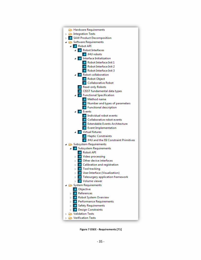
Figure 7 OSEE - Requirements [71]
- 36 -
Details of each requirement level come from the product specification directly. In Figure 7, the
system requirements include objective, references, robot system overview, performance
requirements, safety requirements and design constraints. The software requirements include
only Robot API, which is the software product in the example. The subsystem requirement
includes robot API, video processing, other device interfaces, calibration and registration, tool
tracking, user interface (visualization), telesurgery application framework and volume viewer.
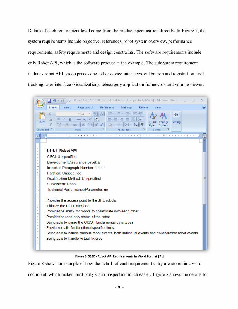
Figure 8 OSEE - Robot API Requirements in Word Format [71]
Figure 8 shows an example of how the details of each requirement entry are stored in a word
document, which makes third party visual inspection much easier. Figure 8 shows the details for

- 37 -
Robot API requirements in Figure 7. OSEE provides a new perspective to structure the
requirement documents.
4.2.3 Software design and implementation
The design details and models can be managed hierarchically in OSEE and implemented by
other software. In Figure 9, the Robot API is required to handle single events such as Backward,
Forward, Left Turn and Right Turn. The detailed implementation of the event state machine is
built in TOPCASED [73], another open platform software what we will introduce in section
4.2.11.
Figure 9 OSEE - TOPCASED Info Tracker [71]

- 38 -
4.2.4 Software testing
Software verification tests are necessary to ensure the software product complies with the
requirements of specification and regulations. Software validation tests are important to ensure
the software product meets the needs of the customers. Integration tests make sure the hardware
and software work as a complete system.
Figure 10 OSEE – Test M anagement [71]
Figure 10 shows how all the tests are organized in OSEE. For integration, we check the
connection integration, subsystem integration and system integration. For verification, functional
tests, normal range tests and robustness tests are created separately. As for validation, we need to
cover the functions for both single robot case and multiple robot case.

- 39 -
4.2.5 Traceability management
Figure 11 OSEE – Traceability [72]
As shown in Figure 11, product decomposition, requirement management, software design,
implementation, verification tests and validation tests are not stand alone information. The
requirements are allocated to blocks defined in the product decomposition stage. The design has
to comply with the requirements. The implementation has to follow the design. The tests are
generated according to the design and verify the implementation. OSEE provides the possibility
to manage the complicated relationship by proper assignment of artifacts and transactions.

- 40 -
Figure 12 OSEE – Skywalker [71]
Besides logically organizing all the artifacts, OSEE also provides a visual hierarchy for review
demonstration, the Skywalker. In Figure 12, the Skywalker draws the relationship of all the
system components in a diagram. We can trace the Robot_API design back to Robot API
Subsystem with Robot API requirements. If we go up further, we can trace to robot system and
system requirements. We can show a Skywalker diagram for any design segment.

- 41 -
4.2.6 Team management
The project can be managed based on the team unit in OSEE. Teams can be created for processes
within each project. Teams can also be shared among different projects if multiple projects are
managed in parallel. In Figure 13, the SAW and CIS project are both active independently, while
the process team and tools team are shared by both SAW and CIS.
Figure 13 OSEE - Te am M anagement [71]

- 42 -
4.2.7 User management
In Figure 14, User ID uniquely identifies the user name, Human Resource ID (HRID) and
(Global User ID) GUID together with their email address. Access privilege can be granted by
setting the user to active. Since user data is also treated as an artifact in OSEE, all the changes to
user data will be recorded.
Figure 14 OSEE - User Management [71]

- 43 -
4.2.8 Version control
Each build can be assigned a build number and the relationships between each build can be
viewed as a diagram. In our Figure 15, SAW_bld_1 has consecutive build numbers from 17 to 25.
SAW_bld_1 progresses to build 26 and 90 of SAW_bld_2. Build 91 and 97 have conflicted
changes, which means the changes come from these two builds cannot merge together. The
project manager has to solve the conflict or create another branch if necessary. The project can
move on through different branches and merges together whenever necessary thanks to the
branch and merging ability provided by OSEE. The reason why there is no continuous build
number in Figure 15 is because in the example, there are multiple software branches going on at
the same time. A lot of updates and fixes go to other branches instead of SAW_Bld_1 and
SAW_Bld_2.
Figure 15 OSEE - Version Control [71]

- 44 -
4.2.9 Release management
Certain builds can be assigned a version number for release to other people of interest. Version
reports can be automatically generated based on the current condition of the build. For each
version, user has the choice of releasing it or not. For the sample SAW project, SAW_Bld_1 is
released and the version report is generated in Figure 16.
Figure 16 OSEE - Release Management [71]

- 45 -
4.2.10 OSEE for DO-178C compliance
The OSEE framework introduces a versatile tool set allowing for remote event services, indexing
and tagging, dynamic searching, dynamic artifact model, multi-level transaction, multi-level
branching, data store adapter, access control, version control, session management and
authentication and object-oriented persistence. Based on such a versatile framework, the OSEE
application works very well for life-cycle management, requirement management, configuration
management, traceability management, workflow management, task scheduling, coverage,
metrics, reporting, etc. Companies and universities such as Boeing, General Motors, Lockheed
Martin, Arizona State University and Auburn University have shown great interest in the OSEE
solution [74].

- 46 -
4.2.11 TOPCASED
The Tool-kit in OPen-source for Critical Applications & SystEms Development (TOPCASED)
[73] aims at providing seamless process and open source tools from system design to final
product.
TOPCASED can greatly reduce the development costs for automotive, avionic and aeronautical
embedded systems. The supporting of model based system engineering enhances product
competitiveness and maturity, and reduces the time to market delay. TOPCASED targets
products with limited market, comparatively long life and high durability. It’s a great tool for
developing a software product targeting the DO-178 standards. TOPCASED supports Model-
driven Engineering [75], which is a software development methodology that reuses standardized
models to maximize design compatibility and simplify the design process.
In Figure 17, we used TOPCASED to create a model for left turn right turn state machine, which
is mentioned in the OSEE project earlier in Figure 9. The “clock” synchronizes the “TurnSignal”
behavior. “TurnSignal” is controlled by “commando” with the “clock”.

- 47 -
Figure 17 Example Component Di agram [73]
The model is constructed in the Unified Modeling Language (UML) [76], which makes use of
component modeling, object modeling, business modeling and data modeling techniques to
create visualized architectural blueprints for object oriented software systems. The concept
supports object oriented programming.

- 48 -
Figure 18 Example UML File [73]
In Figure 18, we encapsulate attributes and behaviors into classes. Class Commodo, Class
TurnSignal and Class Clock are instantiated in Class System. Signal CommandoUp and
CommandoDown are sent from user to the Class Commando to control the system. Signal
Enable, Signal Disable and Signal ClockTick are sent from Class Clock to Class TurnSignal for
master control and event synchronization. Association gives the connections between each Class.
Signal Event represents the state machine events triggered by signals. Therefore we have the uml
file shown in Figure 18 for the diagram.

- 49 -
Figure 19 UML Model Validation [73]
As shown in Figure 19, we choose to validate the model after design. TOPCASED is able to
detect architectural problems of the model. In our case, 64 errors are detected, most of which are
sending and receiving signal information mismatches or important attributes not defined.

- 50 -
Figure 20 Generating Code from UML Model [73]
TOPCASED supports the great feature of converting a model to code. As shown in Figure 20,
you can choose to output the file in different programming languages, such as State Machine
Code or C. The output file can be compiled and executed directly. This feature works better for
well-defined models. If the model is incomplete or defined in the wrong way, the tool won’t fix
the issues for you. It may generate code with even more issues.

- 51 -
4.2.12 CPPCheck
CPPCheck is the static analysis tool we choose for our open source tool chain. It detects neither
syntax errors nor stylistic issues in the code. Instead, it identifies bugs that normally cannot be
detected by C/C++ compilers [45].
Figure 21 CPPcheck Features [45]
Figure 21 lists the major issues CPPcheck can detect. All of them are very common in today’s
designs. A lot of freeware can detect errors but not all freeware tools will issue warnings for
potential issues.
Figure 22 Shift Negative Value W arning
In the robot API example, CPPcheck detected the potential issue of shifting negative values as
shown in Figure 22. This potential issue is compiler dependent and not all of the compilers can
interpret it as expected. Therefore such warnings are crucial, hence such errors must be fixed.

- 52 -
5. CASE STUDY: BLACKBOX DECODER PROJECT
DO-178C includes a guideline for the safety critical software design life cycle. It only defines
what needs to be done, not how to do anything. Therefore there are huge gaps between the
guideline and the implementation. We use the BlackBox Decoder project to demonstrate how to
use the above mentioned open source tools to design software that’s compatible with DO-178C
standards.
Figure 23 Cleanflight Github Projects Overview [77]
Cleanflight [78] is a community driven open source project on Github. It is flight controller
firmware which can be used on multi-rotor craft and fixed wing craft. As shown in Figure 23, the
BlackBox Decoder belongs to the Blackbox Tools project. In order to make full use of the
Blackbox hardware, 3 projects are initiated at the same time, the Black Firmware project, the
Blackbox Tools project and the Blackbox Log Viewer project. The BlackBox Firmware will
capture the video and encode the stream on the fly. The BlackBox decoder can run on the remote

- 53 -
controller so that personnel on the ground can stream the video in real time. It can also be used
offline to decode the video for analysis. The Blackbox Log View can sync the decoded Blackbox
data with the video to give us a better understanding of what is happening during the flight.
Figure 24 is the internal process flow of the BlackBox decoder.
Figure 24 BlackBox Decoder Internal Flow

- 54 -
The Blackbox Decoder initializes the platform with POSIX (Portable Operating System Interface
[79]) attributes to resolve compatibility issues across different platforms. Without such POSIX
attributes, there might be issues when people try to compile on different UNIX systems. Then it
detects the command line options and configures the parameters, such as output destination, the
gps merging option, the current meter scale and the unit of current, height, rotation, acceleration,
etc, accordingly. The Cleanflight firmware adopts Proportional-Integral-Derivative (PID)
controller, which is very popular among drone families. If the input data comes from a real time
stream of the PID controller, it will use the stream IO utility to capture the data. Otherwise the
data will be loaded from the log file. The binary data will be captured and stored in a predefined
data structure and decoded accordingly.
The binary data is composed of header and body. A typical header as shown in Figure 25:

- 55 -
Figure 25 Typical Header for Blackbox Log
With PID controller, there will be axisP, axisI and axisD. In order to accurately describe the
aircraft position in space, the data is recorded in 3 dimensions, i.e. axisP[0], axisP[1], axisP[2],
axisI[0], axisI[1], axisI[2], axisD[0], axisD[1] and axisD[2]. The rcCommand[0:3] represents
control command vector. Gyrodata[0:2] records the vector from gyroscope. accSmooth[0:2] is
the vector from accelerometer. Motor[0:2] is the state of the motor speed controller.
The body parts are all binary data. The data is encapsulated in frames. Each line contains the data
in one frame. It borrows the idea from video compression, where intra frame contains all the
information of the current frame while inter frame contains only the relative information to

- 56 -
neighboring frames. In video compression technique, the inter-frames and intra-frames refer to I
and P frames. The I frame data and P frame data cannot be differentiated after decoding. It helps
to sync up with the video if captured. After decoding, it will be stored in comma separated
format as shown in Figure 26.
Figure 26 BlackBox Decoder D ata
Following the DO-178C procedure, first, we need to decide the Design Assurance Level (DAL)
that our software falls into. Here we list all 5 categories below, repeated from Section 2.5:
“A: Catastrophic – Failure may cause a crash. Error or loss of critical function required to
safely fly and land aircraft.
B: Hazardous – Failure has a large negative impact on safety or performance, or reduces the
ability of the crew to operate the aircraft due to physical distress or a higher workload, or
causes serious or fatal injuries among the passengers. (Safety-significant)
C: Major – Failure is significant, but has a lesser impact than a Hazardous failure (for example,
leads to passenger discomfort rather than injuries) or significantly increases crew workload
(safety related)
D: Minor – Failure is noticeable, but has a lesser impact than a Major failure (for example,
causing passenger inconvenience or a routine flight plan change)
E: No Effect – Failure has no impact on safety, aircraft operation, or crew workload.” [11]

- 57 -
BlackBox Decoder project aims at interpreting the drone blackbox data in a way that human
beings can understand. The original input is binary. The failure of this piece of software will lead
to minor damage to the system and therefore it belongs to Level D.
Figure 27 Case Study Diagram
After the DAL level and the target guidelines are clear, we begin with the software planning
process. Figure 27 shows the schematic diagram of the system components and requirements
(Purple and Blue boxes in the left). The Blackbox Decoder project is partitioned into
Configuration, Logic and IO. The top level system requirement is defined for Blackbox Decoder.
The subsystem requirement is defined for each component such as Configuration, Logic, IO.
Relying on these well defined requirements, software engineers begin to develop the system
from bottom up. First things first, we need the Software Requirement description that outlines
the software purpose, scope and requirements in general.
- 58 -
As we pointed out in the beginning of this chapter, DO-178C defines what needs to be done but
doesn’t specify how to do it. In this Blackbox Decoder project, we follow Bruegge’s book [32]
for the requirement elicitation.
Functional requirements describe how the system responds to inputs without the implementation
details [32]. Here are 3 sample Blackbox Decoder (BBD) functional requirements:
BBD is a decoder which translates the binary data captured by the Blackbox to human
readable data.
BBD can either take an input streaming data from PID or the recorded data from a log
file as inputs.
BBD should also decode the GPS, Accelerometer and Gyroscope data if such data is also
input
Non-functional requirements defines all the other aspects other than the functional requirements,
such as usability requirements, reliability requirements, performance requirements,
supportability requirements, implementation requirements, interface requirements, operations
requirements, packaging requirements and legal requirements [32]. Here are 3 BBD non-
functional requirements we derived:
Users should input no more than 1 command to finish the decoding process (Usability
Requirement)
BBD should display the correct output within 1 minute of decoding for the maximum
allowed input size (Performance Requirement)

- 59 -
All the software related with BBD will be written in C, to comply with the BBD
firmware (Implementation Requirement)
Organizing the Software Requirements in a systematic way, the Software Requirement
Document can be generated to support future development. With the Software Requirement
document in hand, the team leader can lay out the Plan for Software Aspects of Certification
(PSAC v1.0), which provides an overview of the system. It covers the software overview, the
certification considerations, organizational responsibility, life cycle processes and the software
life cycle data. It’s the ultimate guidance for the whole project.
Thereafter, Software Development Plan (SDP v1.0) covers all the details in the software
development phase. Software Verification P lan (SVP v1.0) and Software Verification Cases and
Procedures Document (SVCP v1.0) cover all the details in the software verification phase.
Software Quality Assurance Plan (SQAP v1.0), together with Software Configuration
Management P lan (SCMP v1.0), identifies and controls major software changes, and ensures that
change is being properly implemented and reported. The software overview, architecture, logic
component breakdown, configuration management, version control, personnel control are all
done by OSEE. Therefore the major parts of these documents can be pulled from OSEE.
Based on the software requirement document, software development plan and software
architecture, Software High Level Requirements Document (SHLRD v1.0) and Software High
Level Signal Dictionary (SHLSD v1.0) are carefully designed. With more details added in, the
- 60 -
Software Low Level Requirements Document (SLLRD v1.0) and Software Low Level Signal
Dictionary (SLLSD v1.0) cover all the functions and signals that might be used in the design.
Guided by the SLLRD and SLLSD, the source code is then developed by the programmer. It’s
then compiled by gcc in the target platform to the object code.
Software validation is done against the SLLRD, SHLRD and software requirements. This makes
sure all the requirements are aligned. It’s checked manually.
SVP and SVCP entail all the necessary verification aspects. CPPcheck is applied here for the
static analysis.
DO-178C Annex A defines 28 objectives that DAL level D should follow. We check against
each list item to make sure our design process complies with DO-178 guideline. In each list item,
we note the tools used:
Table A-1, Software planning process:
1) Software development and integral processes activities are defined in Figure 28:
We generated Software Development P lan for the BlackBox Decoder project (Named
as BBD in Figure 28). The integral processes are the software verification process,
the software configuration management process, the software quality assurance
process, and the certification liason process. We generated Software Verification Plan,
Software Configuration Management Plan and Software Quality Assurance Plan.
OSEE is used in this phase.

- 61 -
Figure 28 Software Pl anning Process
2) Additional considerations are addressed:
Additional considerations include specific features that may affect the certification
process, for example, alternative methods of compliance, tool qualification,
previously developed software, user modified software, COTS software, etc. We
developed Tool Qualification Plan for this project. We discussed how to qualify
operating system, compiler, software develop IDE and verification tools. OSEE is
used in this phase.
Table A-2, Software development process:
3) High-level requirements are developed:

- 62 -
Figure 29 High Level Requirements
In Figure 29, our high-level requirements include project requirements and
requirements for platform initialization, parse command line options, prepare output
stream, parse header, parse frame data, merge GPS frame, update summary statistics,
garbage collection and design constraints. OSEE is used in this phase
4) Derived high-level requirements are defined:
Derived requirements are requirements that are not directly traceable to higher level
requirements. For example, interrupt requirements. Since we are developing the
software part of the system only in this project, we won’t have this part. Everything in
our project can be traced to the high level requirements. OSEE is used in this phase.
5) Software architecture is developed:
The Black Box Decoder architecture is developed from high-level requirement. It
defines major blocks and draws schematic diagrams. OSEE is used in this phase.

- 63 -
6) Low-level requirements are developed:
Figure 30 Low Level Requirements
As shown in Figure 30, the Black Box Decoder low level requirement defines
parameters, interfaces and major functions for each block. OSEE is used in this phase.
7) Derived low-level requirements are defined:
The Black Box Decoder utility functions, such as matrix rotation, comparison
functions, and signed to unsigned binary data conversions. OSEE is used in this phase.
8) Source code is developed:
The Black Box Decoder source code is written in C language. It follows the guidance
of software architecture and low level requirements. OSEE and Dev-C++ is used in
this phase.
9) Executable object code is produced and integrated in the target computer:

- 64 -
The executable code is compiled and linked in Visual C suite, in windows
environment. It’s also compatible with Mac OS and Linux environment. Dev-C++ is
used in this phase.
Table A-3, Verification of outputs of software requirements process:
10) Software high-level requirements comply with system requirements:
The hardware is not involved in this project. Therefore the system requirements are
the same as high-level requirements. We don’t need to verify this item.
11) High-level requirements are accurate and consistent:
We described the high level requirements in such a way as to make sure they are
accurate, unambiguous and sufficiently detailed and that the requirements do not
conflict with each other. OSEE is used in this phase.
12) High-level requirements are traceable to system requirements:
Same as 10). The hardware is not involved in this project. Therefore the system
requirements are the same as high-level requirements. We don’t need to verify this
item.
Table A-4, Verification of outputs of software design process:
13) Software partitioning integrity is confirmed:
We check the software partitioning against the software requirement to make sure the
separation of design modules aligns with the highest level requirements. OSEE is used in
this phase.
Table A-5, Verification of outputs of software coding & integration process :

- 65 -
14) For each module, the code is checked against the low level requirements to make sure
the coding is correct.
We use the text comparator to make sure the design code is copied over correctly
during integration. After all, we have the connection test to make sure all the
connections between modules are correct and we have the function test to make sure
the integration process are finished successfully. OSEE and Dev-C++ are used in this
phase.
Table A-6, Testing of outputs of integration process:
15) Executable object code is robust with high-level requirements:
Two types of tests are included in the tests: normal range test cases and robustness test
cases. The normal range tests will randomize all the input data, while the robustness test
will inject errors accordingly. In our example, as you can see from table 7, we run the
normal range test cases on all the inputs, including loopineration, time, axisP/I/D,
rcCommand, gyroData, accSmooth and motor. We get the pass message of “Decode done”
on all them. There are 2 rounds of robustness test cases following by. In the 1st round we
remove the input one by one from the input file and check the result. The “Failed to
decode Frame” error message is output to the screen. The 2nd
round tests replace the legit
inputs with out of bound values. The “Frame unusable due to prior corruption” error
message should show up. We do see the failed messages as expected.
All the tests have to pass to complete this phase. OSEE and CPPCheck are used here.

- 66 -
Normal Range Test Cases Robustness Test Cases
Inputs Type Missing this input Out of Range
loopIIteration int Decode done Error message "Failed to decode frame"
Error message "Frame unusable due to prior corruption"
time int Decode done Same as above Same as above
axisP/I/D int Decode done Same as above Same as above
rcCommand int Decode done Same as above Same as above
gyroData int Decode done Same as above Same as above
accSmooth int Decode done Same as above Same as above
motor int Decode done Same as above Same as above Table 7 Normal Range Tests and Robustness Tests
16) Executable object code is compatible with target computer:
There are 3 different versions of Black Box Decoder executable object code, generated
based on windows, Mac OS and Ubuntu. Black Box Decoder executable object code is
generated and tested in all three environments. Dev-C++ is used in this phase.
Table A-7, Verification of verification process results:
17) Test coverage of high-level requirements is achieved:

- 67 -
Figure 31 Software Verification and Testing
In Figure 31, all the verification activities are recorded. We achieved 100% test coverage
against Black Box Decoder high level requirements. OSEE and CPPTest is used in this
phase.
Table A-8, Software configuration management process:
18) Configuration items are identified:
Each module we defined in this system is a configuration item. All of them are identified
and recorded in the OSEE system. OSEE is used in this phase.
19) Baselines and traceability are established:
As can be seen from Fig 32, whenever we started a new phase in the software
development phase, we would create a baseline as a new starting point. Therefore the

- 68 -
traceability can be achieved with ease. Every version and every change can be traced
according to the branch change report. OSEE is used in this phase.
Figure 32 Branch Management
20) Problem reporting, change control, change review, and configuration status
accounting are established:
Figure 33 Problem Reporting System

- 69 -
As Figure 33 shows, all the problems are reported and recorded with details. OSEE
keeps all the information, from originator, to responsible team and to the problem
details and solutions.
Figure 34 Branch Change Report
Figure 34 demonstrates the change report feature which lists all the changes between
current version the parent branch. It makes change review and change control much
easier. OSEE is used in this phase.

- 70 -
21) Archive, retrieval, and release are established:
In Figure 35, OSEE provides a versatile version and release control system. Version
can be easily made for each team. Releases are made for general use after each
version is stabilized. Differences between versions can be viewed in the report. OSEE
is used in this phase.
Figure 35 Version and Release Control
22) Software load control is established:
This software is not designed for multi-user system. It can only be deployed in one
console and drive one load per machine. Therefore we don’t consider the load control in
this project.
23) Software life cycle environment control is established:

- 71 -
The whole software life cycle is maintained in OSEE and the environment setting is kept
consistent throughout the whole process, which can be revealed from the OSEE records.
OSEE is used in this phase.
Table A-9, Software quality assurance process:
24) Assurance is obtained that software development and integral processes comply with
approved software plans and standards:
The Black Box Decoder assurance team works closely with the design and
verification/testing team to look at every detail of the software development and integral
steps. All the modules can be traced back to the software plan. OSEE traceability makes
sure the software assurance can be done with minimum workload. OSEE is used in this
phase.
25) Software conformity review is conducted:
OSEE keeps track of all the reviews made against the workflow. It’s called by the
originator and all the designees have to reach consensus and authorize the workflow to
move on. OSEE is used in this phase.
Table A-10, Certification liaison process:
26) Communication and understanding between the applicant and the certification
authority is established:
The project manager should submit all the documents and supporting materials and
the certification authority should layout the basic guidelines for the whole projects. In
this case, we don’t have any connection with the certification authority and therefore

- 72 -
cannot describe how they react to all the supplied materials and how they would give
advice to the project manager.
27) The means of compliance is proposed and agreement with the plan for software
aspects of certification is obtained:
We will use Software Accomplish Summary (SAS) to checked against the Plan for
Software Aspect of Certification (PSAC). PSAC defines what we intend to do while
SAS records what we did. OSEE is used in this phase.
28) Compliance substantiation is provided:
SAS is checked against the PSAC to ensure the deliverable aligns with our initial plan.
OSEE is used in this phase.

- 73 -
6. CONCLUSIONS AND FUTURE WORK
This thesis focuses on developing safety critical embedded software compliant with the DO-
178C guideline. We propose a freeware tool chain to support every stage of the software
development life cycle, including planning, design and verification. These open source software
tools have gone through strict testing and can achieve results similar to expensive COTS
software suites in the market. A case study is carefully examined to show readers how to use the
software step by step.
Although the open source tools can alleviate the pain of certifying safety critical software to
conform to the DO-178 standard, their performance is far from perfect. The OSEE does a great
job on bookkeeping for all the requirement data and configuration management data, but tools
such as TOPCASED need to improve more to embrace the fast changing software standards.
Since one of the major updates from DO-178B to DO-178C is the support for Model Based
Design and Object Oriented programming, TOPCASED needs to add support for C++ and Java
if possible.
Another point worth mentioning here is that the DO-178 guidelines only define what needs to be
done, but not the how this is to be done. It’s the developer’s job to work closely with the Design
Engineering Representative (DER) [80] to fulfill the objectives associated with the
corresponding DAL.

- 74 -
Future directions of this work can consist of bringing in the FAA DER to illustrate more details
of the DO-178C qualification process. As we design the software, we look at the project from a
developer point of view. The DER will introduce a completely different perspective, and they
may have a different interpretation of the DO-178C guideline. These discrepancies should be
identified and resolved at an early stage.
In addition, more open source software should be investigated and included in the tool chain.
There are many additional qualified freeware tools targeting certain specific software
development phases. The more tools we have, the easier the development process would be. At
the same time, some tools might be outdated or no longer supported. The tool chain should be
updated accordingly.

- 75 -
References
[1] S. Rogerson, "The Chinook Helicopter Disaster," [Online]. Available:
http://www.ccsr.cse.dmu.ac.uk/resources/general/ethicol/Ecv12no2.html. [Accessed 25/ 11/
2014].
[2] W. v. Diermen, "F-22 Raptor," [Online]. Available: http://www.f-
22raptor.com/index_airframe.php#1992. [Accessed 23/ 11/ 2014].
[3] "DO-178B," Wikipedia, [Online]. Available: http://en.wikipedia.org/wiki/DO-178B#cite_note-1.
[Accessed 26/ 11/ 2014].
[4] RTCA, "DO-178C," [Online]. Available: https://en.wikipedia.org/wiki/DO-178C. [Accessed 26/ 11/
2014].
[5] Boeing, "Statistical Summary of Commercial Jet Airplane Accidents, Worldwide Operations 1959-
2012," Statistical Summary, 2015.
[6] "Commercial off-the-shelf," Wikipedia, [Online]. Available:
http://en.wikipedia.org/wiki/Commercial_off-the-shelf. [Accessed 15/ 11/ 2014].
[7] "MathWorks," Matlab, [Online]. Available: http://www.mathworks.com/solutions/aerospace-
defense/standards/do-178b.html. [Accessed 28/ 11/ 2014].
[8] "IBMDeveloperWorks," IBM, [Online]. Available:
https://www.ibm.com/developerworks/community/blogs/invisiblethread/entry/do-178b-
aerospace-solutions?lang=en. [Accessed 29/ 11/ 2014].
[9] "aNimble Platform," [Online]. Available: http://sourceforge.net/projects/nimble/. [Accessed 05/
11/ 2014].
[10] "MDT/UML2," Eclipse, [Online]. Available: http://wiki.eclipse.org/MDT-UML2. [Accessed 30/ 11/
2014].
[11] "ARP4761," Wikipedia, [Online]. Available: http://en.wikipedia.org/wiki/ARP4761. [Accessed 27/
11/ 2014].
[12] "Hazard Analysis," Wikipedia, [Online]. Available: http://en.wikipedia.org/wiki/Hazard_analysis.
[Accessed 23/ 11/ 2014].
[13] "ARP4754," Wikipedia, [Online]. Available: http://en.wikipedia.org/wiki/ARP4754. [Accessed 03/
11/ 2014].
[14] RTCA, "Advisory Circular of RTCA Document RTCA/DO-178B," [Online]. Available:
http://www.airweb.faa.gov/Regulatory_and_Guidance_Library/rgAdvisoryCircular.nsf/0/dcdb1d20
31b19791862569ae007833e7/$FILE/AC20-115B.pdf. [Accessed 21/ 11/ 2014].

- 76 -
[15] "DO-254 together," [Online]. Available: http://www.do254.com/. [Accessed 10/ 11/ 2014].
[16] "DO-254," Wikipedia, [Online]. Available: http://en.wikipedia.org/wiki/DO-254. [Accessed 04/ 11/
2014].
[17] "DO-254," Mentor Graphics, [Online]. Available: http://www.mentor.com/solutions/do-254/.
[18] "Military Standard Software Development and Documentation". Patent AMSC No. N7069, 05
December 1994.
[19] "Military Standard Defense System Software Development". Patent AMSC No. N4327, 29 February
1988.
[20] "Software Considerations in Airborne Systems and Equipment Certification," RTCA, Inc., 1982.
[21] "Software Considerations in Airborne Systems and Equipment Certification," RTCA, Inc., 1985.
[22] R. D. Busser and M. Blackburn, "Guidelines for Software Tool Qualification," Software Productivity
Consortium NFP, Inc., 2003.
[23] "Radio Technical Commission for Aeronautics," RTCA, Inc., [Online]. Available:
http://www.rtca.org/. [Accessed 14/ 11/ 2014].
[24] "The European Organisation for Civil Aviation Equipment," EUROCAE, [Online]. Available:
http://www.eurocae.net/. [Accessed 05/ 11/ 2014].
[25] "RTCA DO-178B, Software Considerations in Airborne Systems and Equipment Certification," RTCA
Inc., Washington, D.C., 1992.
[26] C. Lee, "Introduction to DO-254," ERA Technology Ltd, 2013.
[27] "IEEE Standards for Software Safety Plans," IEEE Standards Association, 1994.
[28] P. Stachour, "High Integrity Software for High Integrity Systems," in SIGAda 2001, 2001.
[29] "Modified condition/decision coverage," [Online]. Available:
https://en.wikipedia.org/wiki/Modified_condition/decision_coverage. [Accessed 14/ 05/ 2016].
[30] "DO-178C," Wikipedia, [Online]. Available: http://en.wikipedia.org/wiki/DO-178C. [Accessed 25/
11/ 2014].
[31] "Transitioning to RTCA DO-178C/DO-278A: A Business Manager Brief," Foliage, [Online]. Available:
http://www.onlineamd.com/FileUploads/file/AER-2012-Transitioning%20to%20RTCA%20DO-
178C%20DO-278A_final.pdf. [Accessed 11/ 11/ 2014].
[32] B. Bruegge and A. H. Dutoit, Object-Oriented Software Engineering, Pearson, 2009.
[33] R. S. Pressman and B. R. Maxim, Software Engineering: A Practitioner's Approach, McGraw-Hill

- 77 -
Education, 2014.
[34] RTCA, "RTCA/DO-178C "Software Considerations in Airborne Systems and Equipment
Certification"," Radio Technical Commission for Aeronautics, 2011.
[35] "DO-178B Software Development & Certification - Project Planning Phase," Certon, [Online].
Available: http://www.certon.com/do-178b_planning.php. [Accessed 10/ 11/ 2014].
[36] B. Brosgol and G. Gicca, "Trusting the tools: An agile approach to tool qualification for DO-178C,"
Military Embedded Systems, [Online]. Available: http://mil-embedded.com/articles/trusting-tools-
agile-approach-tool-qualification-do-178c/. [Accessed 10/ 11/ 2014].
[37] L. Rierson, "Developing Safety-Critical Software: A Practical Guide for Aviation Software," Taylor &
Francis Group, 2013, p. 322.
[38] A. J. Kornecki and J. Zalewski, "The Qualification of Software Development Tools From the DO-178B
Certification Perspective," Software Engineering Technology, 2006.
[39] "OSEE: The Open System Engineering Environment," Eclipse, [Online]. Available:
https://eclipse.org/osee/.
[40] "rmToo - Requirements Management Tool," [Online]. Available: http://rmtoo.florath.net/.
[Accessed 11/ 11/ 2014].
[41] "TOPCASED: The Open Source toolkit for critical systems," PolarSys, [Online]. Available:
https://www.polarsys.org/topcased. [Accessed 01/ 11/ 2014].
[42] "GCC, the GNU Compiler Collection," [Online]. Available: https://gcc.gnu.org/. [Accessed 15/ 11/
2014].
[43] "GDB: The GNU Project Debugger," [Online]. Available: https://www.gnu.org/software/gdb/.
[Accessed 01/ 11/ 2014].
[44] "AdaControl," ADALOG, [Online]. Available: http://www.adalog.fr/en/adacontrol.html. [Accessed
06/ 11/ 2014].
[45] "Cppcheck : A tool for static C/C++ code analysis," [Online]. Available:
http://cppcheck.sourceforge.net/. [Accessed 07/ 11/ 2014].
[46] D. S. Wilkerson, K. Chen and S. McPeak, "Oink : a Collaboration of C/C++ Tools for Static Analysis
and Source-to-Source Transformation," [Online]. Available:
http://danielwilkerson.com/oink/index.html.
[47] "CQUAL : A tool for adding type qualifier to C," [Online]. Available:
https://www.cs.umd.edu/~jfoster/cqual/. [Accessed 27/ 11/ 2014].
[48] "The Cheddar Project : a free real-time scheduling analyzer," [Online]. Available: http://beru.univ-

- 78 -
brest.fr/~singhoff/cheddar/#Ref2. [Accessed 10/ 11/ 2014].
[49] "The gnatmem Tool," [Online]. Available:
http://www.cs.fsu.edu/~baker/ada/gnat/html/gnat_ugn_22.html#SEC239. [Accessed 23/ 11/
2014].
[50] "QEMU : Open Source Processor Emulator," [Online]. Available: http://wiki.qemu.org/Main_Page.
[Accessed 30/ 11/ 2014].
[51] "BloodshedSoftware," [Online]. Available: http://www.bloodshed.net/devcpp.html. [Accessed 13/
06/ 2016].
[52] "FitNesse : The fully integrated standalone wiki and acceptance testing framework," FitNesse,
[Online]. Available: http://www.fitnesse.org/FrontPage. [Accessed 19/ 11/ 2014].
[53] "cfix," [Online]. Available: http://www.cfix-testing.org/unit-testing-
framework/windows/doc/index.html. [Accessed 04/ 11/ 2014].
[54] "Check : Unit Testing Framework for C," [Online]. Available: http://check.sourceforge.net/.
[Accessed 08/ 11/ 2014].
[55] "CppTest," [Online]. Available: http://cpptest.sourceforge.net/. [Accessed 10/ 11/ 2014].
[56] "cu," GitHub, [Online]. Available: https://github.com/danfis/cu. [Accessed 18/ 11/ 2014].
[57] "GNU Make," [Online]. Available: https://www.gnu.org/software/make/. [Accessed 06/ 11/ 2014].
[58] "CVS - Concurrent Version System," [Online]. Available: http://www.nongnu.org/cvs/. [Accessed
22/ 11/ 2014].
[59] "Apache Subversion - Enterprise-class centralized version control for the masses," [Online].
Available: https://subversion.apache.org/. [Accessed 05/ 11/ 2014].
[60] J. Rossberg, Application Life Cycle Management, Apress, 2014.
[61] Introduction to Software Engineering/Process/Methodology, Wikibooks, 2015.
[62] K. Petersen, C. Wohlin and D. Baca, The Waterfall Model in Large-Scale Development, Springer
Berlin Heidelberg, 2009.
[63] B. Boehm, J. A. Lane, S. Koolmanojwong and R. Turner, The Incremental Commitment Spiral Model:
Principles and Practices for Successful Systems and Software, Addison-Wesley Professional, 2014.
[64] "Incremental Build Model," Wikipedia, [Online]. Available:
https://en.wikipedia.org/wiki/Incremental_build_model. [Accessed 13/ 11/ 2014].
[65] J. Shore, The Art of Agile Development: Pragmatic guide to agile software development, O'Reilly
Media, 2007.
- 79 -
[66] R. Murch, Rapid Application Development Lifecycle- RAD - The Complete Guide, Macmillan Coll Div,
2012.
[67] "Cowboy Coding," Wikipedia, [Online]. Available: https://en.wikipedia.org/wiki/Cowboy_coding.
[Accessed 26/ 11/ 2014].
[68] Eclipse, "Eclipse Project," [Online]. Available: https://eclipse.org/eclipse/. [Accessed 27/ 05/ 2016].
[69] J. P. Womach and D. T. Jones, in Lean Thinking: Banish Waste and Create Wealth in Your
Corporation, Productivity Press, 2003, p. 396.
[70] "OSEE Components," Eclipse, [Online]. Available:
http://www.eclipse.org/osee/documentation/overview/components.php#ats. [Accessed 6/ 11/
2014].
[71] B. Vagvolgyi, S. P. Dimaio, A. Deguet, P. Kazanzides, R. Kumar, C. Hasser and R. H. Taylor, "The
Surgical Assistant Workstation," Insight Journal, p. 2, 2008.
[72] R. Brooks, D. Dunne and R. Escobar, "From www.eclipse.org/osee to deployment," 2009.
[73] "TOPCASED - The Open System Toolkit for Critical Systems," [Online]. Available:
http://www.topcased.org/. [Accessed 14/ 11/ 2014].
[74] Boeing, "OSEE Creation Review," Boeing, 2007.
[75] "Model Driven Engineering," [Online]. Available: http://en.wikipedia.org/wiki/Model-
driven_engineering. [Accessed 27/ 11/ 2014].
[76] "Unified Modeling Language," Wikipedia, [Online]. Available:
http://en.wikipedia.org/wiki/Unified_Modeling_Language. [Accessed 05/ 11/ 2014].
[77] Cleanflight, "Cleanflight: Open Source Flight Control System," [Online]. Available:
https://github.com/cleanflight. [Accessed 30/ 05/ 2016].
[78] O. Source, "Cleanflight," [Online]. Available: http://cleanflight.com/. [Accessed 30/ 05/ 2016].
[79] "POSIX," Wikipedia, [Online]. Available: https://en.wikipedia.org/wiki/POSIX. [Accessed 02/ 06/
2016].
[80] F. A. Administration, "Designees & Delegations - Designated Engineering Representative (DER),"
[Online]. Available:
https://www.faa.gov/other_visit/aviation_industry/designees_delegations/designee_types/der/.
[Accessed 18/ 06/ 2016].

- 80 -
Appendix A. TUTORIAL
This tutorial can be used by students to aid them in understanding the contemporary design
process for safety critical embedded software. It demonstrates how to use a set of open source
tools step by step.
System requirements:
system with at least 4GB of RAM
Java Runtime Environment (JRE) 1.6. Make sure your Java version is compatible with your
operating system. A 64 bit system requires the 64 bit version of Java. Otherwise, Java may
still work properly on your computer, but our OSEE won’t. You can find the archive here:
http://www.oracle.com/technetwork/java/javase/downloads/java-archive-downloads-javase6-
419409.html
Eclipse Kepler 4.3.2: Please select the correct version based on your operating system -
Windows, linux or Mac OS, 32bit or 64bit. Here is the download link:
http://www.eclipse.org/downloads/packages/eclipse-standard-432/keplersr2
Relational Databases: OSEE comes bundled with H2. However, H2 has its limitations. For
example, H2 database doesn’t support multiple user connections. If you want a full-fledged
relational database, please download and install PostgreSQL from the following link:
https://www.postgresql.org/download/
Eclipse Installation:
Download the OSEE application server and the OSEE client update archive from
http://www.eclipse.org/osee/downloads/

- 81 -
Client Installation:
Start Eclipse, select Help > Intall New Software…
Select the Add… button
Select Archive…, point to the downloaded org.eclipse.osee.client.all.p2.zip
Finish the installation
Don’t restart Eclipse, add the following line to the eclipse.ini file:-
Dosee.application.server=http://localhost:8089
Quick server installation:
Unzip the downloaded org.eclipse.osee.x.server.runtime.zip, which should include the
following files:
configuration
demo
eclipse
etc
plugins
runDemo.bat
runDemo.sh
runHsql.sh
runPostgreSqlLocal.sh
Edit the startup script file runDemo.dat for Windows or runDemo.sh for unix:

- 82 -
For example: -Dosee.application.server.data=" C:/UserData/OseeDemo/demo/binary_data"
Edit the osee.hsql.json file in etc directory:
For example: "jdbc.server.db.data.path": "file:c:/UserData/OseeDemo/demo/hsql/osee.hsql.db"
Run the script file in the command window to start the server
How do we create an Actionable Item (AI)?
We use an example, the Surgical Assistant Workstation (SAW) [71] here for demonstration. It’s
an open source project, which is based on cross-platform C++ component design.
The SAW is a complicated product including chasis, cognitive decision aiding system,
communication system, control system, data management system, electrical system, hydraulics
system, navigation system, propulsion system, robot system, robot survivability equipment and
robot API. In this tutorial we will focus on robot system and robot API.
We need the Design Team and Verification Team in the first place. Tools, Process and Facility
teams are there for support. All the Actionable Items (AIs) shall fall into one of the above
categories.
Task 1. Create the Software Requirement AI and also a Design Team.

- 83 -
Select File -> New -> Other… -> OSEE ATS -> ATS Configuration and type in the
following information as shown in Figure 36:
Team Definition Name: Design
Actionable Item(s) (comma delim): Software Requirements
WorkDefinition Name: WordDef_Team_SawLabs30
Figure 36 Create Software Requirement
Task 2. Create High Level Requirement under Software Requirement and assign to Design Team

- 84 -
Right click Software Requirement AI -> New Child -> Actionable Item and type in the
following information as shown in Figure 37:
Artifact Name: High Level Requirement

- 85 -
Figure 37 Create High Level Requirement

- 86 -
How do we create a team?
Task 1: Create a Design Team
As shown in Figure 38, under Teams, Right click open space -> New Child -> Team Definition
Artifact Name: Design
Figure 38 Create a Te am

- 87 -
How do we relate an Actionable Item to Teams?
Task 1: Relate the High Level Requirement AI to the Design Team
Double click to open the High Level Requirement and in the “Relations” drop down menu, open
the “TeamActionableItem”. Drag and drop the Design Team to “Team Definition”. Now the
High Level Requirement AI and Design Team are associated. You should see the same window
as Figure 39:
Figure 39 Relate Requirements with Te ams
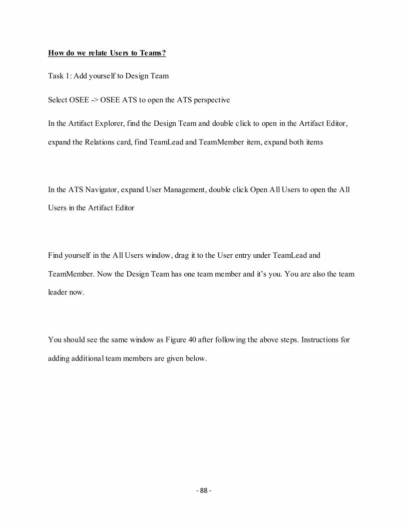
- 88 -
How do we relate Users to Teams?
Task 1: Add yourself to Design Team
Select OSEE -> OSEE ATS to open the ATS perspective
In the Artifact Explorer, find the Design Team and double click to open in the Artifact Editor,
expand the Relations card, find TeamLead and TeamMember item, expand both items
In the ATS Navigator, expand User Management, double click Open All Users to open the All
Users in the Artifact Editor
Find yourself in the All Users window, drag it to the User entry under TeamLead and
TeamMember. Now the Design Team has one team member and it’s you. You are also the team
leader now.
You should see the same window as Figure 40 after following the above steps. Instructions for
adding additional team members are given below.

- 89 -
Figure 40 Relate Users to Te ams
How do we create a branch?
Task1: create SAW_Bld_1 branch
In the Define perspective, open Branch Manager, select the parent you want to branch from,
which is the common branch in this case, right click and select “Branch”, enter the branch name
“SAW_Bld_1” and click OK, as shown in Figure 41:

- 90 -
Figure 41 Create a Branch
How do we import Requirement documents?
Task1: Import the Software Requirement documents to the OSEE system
In the Define perspective, open the Artifact Explorer, in the hierarchical root, right click and
select “New Child”, select “Folder” and type in the requirement name: Software Requirements
Right click the “Software Requirements” folder and select “Import…”, select “OSEE Artifacts”
under “OSEE”, select “Next >”
In the OSEE Artifact Import Wizard, in the “Import Source” select “Browse…”, select the SAW
Software Requirement word document, select “Open”, change the “Select Parser” from “General
Documents (Any Format)” to “Whole Word Document”, click “Select” to select artifact type for

- 91 -
imported data as, also select “MS Word Whole Document” as the imported artifact type and
select “OK”. After you change everything correctly, select “Finish” and you will see a SAW
Software Requirement artifact is created under “Software Requirement” folder, with the same
name as your imported word document name. Figure 42 shows the windows you should see.
Figure 42 Import Requirement Documents

- 92 -
Repeat the above steps to add the following
AIs:
Design
Software Requirements
Software High Level Requirement
Coding
Test
Software Verification P lan
Software Validation Plan
Testing
Facilities
Backups
Break Room
Computers
Network
Vending Machines
Processes
Coding Standards

- 93 -
Config Management
New Employee Manual
Reviews
Tools
Reader
Results Reporter
Timesheet
Website
Teams:
Design Team
YOUR NAME HERE (Team Lead)
Michael John (Project Manager)
Joe Smith (Team Member)
Testing Team
Alex Kay
Facilities Team
IT Team
Bruce
- 94 -
Processes
Candace
Tools
Web Team
Dana
For demonstration, assign yourself te Design Team. Assume you have Michael and Joe for the
Design Team, Alex for the Testing Team, Bruce for the IT Team, Candace for the Process Team
and Dana for the Tools Team. Below you will learn how to use OSEE for configuration
management.
How to use ATS for change tracking:
Task 1: You, as a user, find a problem in a requirement impacting multiple teams, namely
Design, Test, Website and IT. Multiple reviews will be needed:
Decision Review (off Code Team Workflow)
Peer Review (off Test Team Workflow)
In addition, certain tasks will need to be performed off Code Team Workflow
Personnel:
YOUR NAME HERE, Project Engineer (Requirements and Code) , Team Lead

- 95 -
Michael, Project Manager
Joe, Design Engineer
Alex, Test Team Lead
Bruce, IT Team Lead
Dana, Web Team Lead
Requirements Search:
Select the Define perspective window (Window > Open Perspective > Define).
In the Artifact Explorer, click Select Branch...
Select "Blackbox Decoder"
Click "OK"
Search for Item:
Click the Quick Search view
Select the "Blackbox Decoder" branch from the “Select Branch…” box
Enter "command line" in the search string text box
Click the search button
Figure 43 shows the result of the search.

- 96 -
Figure 43 Requirement Search
Requirements Team Workflow
Let’s take a look at "Robot Interfaces" requirement, we want to create an action:
Select the ATS Perspective window (Window > Open Perspective > ATS).
Click the New Action icon
In the “Create ATS Action Dialog”, input the following:
Title: Enter "Robot Interface requirement needs more detail"
Actionable Item: Select "Software Requirements"
Click “Next” button, you should see the same window as Figure 44.

- 97 -
Figure 44 Create an Action
As shown in Figure 45, fill in the following:
Description: Robot Interface requirement is not detailed enough, doesn’t include
the JHU robot descriptions. Needs more details
Change Type: "Problem"
Priority: "3". This is a managerial decision from the project manager. There is no
hard rule of which priority to assign on any given issue. It all depends on the
project manager’s prospective towards it.

- 98 -
Assign the Action to YOUR NAME HERE and then Click Finish. This will generate a
Requirements Team Workflow for the necessary requirements changes. YOUR NAME HERE
will automatically be the originator and Joe is the assignee.
Figure 45 Action Details
Endorse
YOUR NAME HERE has approved the “Requirement Team Workflow”. Ready to transit to
analysis.
Target Version: select “Blackbox Decoder”.
Keep Priority as 3.

- 99 -
Select “Analyze” state and then click “Transition” button.
assign it to Joe, our Design Engineer, for this demo as shown in Figure 46:
Figure 46 Endorse
Analyze
Now, Joe wants to analyze the problem.
Proposed Resolution: fill in "Fix It"
Estimated Hours: 2.5

- 100 -
Since the change will impact testing and coding, corresponding workflows are needed for
both.
Click on the Actionable Items
Select "Coding"
Select "Software Test Plan"
Click OK. The Action View will now show new workflows. Email notifications
have been sent to the Testing Team Lead Alex
Transition to "Authorize". Figure 47 shows the window you should see.

- 101 -
Figure 47 Analyze
Authorize
The Testing Team Lead Alex authorizes the Action.
Work Package: A12345. Work package is a small group of relevant tasks within a project.
Although this is a Testing Team workflow, a decision review is needed from Project
Manager.
Click the Add Decision Review.
As shown in Figure 48, fill the following in the “Create Decision Review” window:
Review Title: "Any Problems with authorizing this?"

- 102 -
Select state to that review will be associated with: "Authorize"
Click OK
Figure 48 Create Decision Review
Decision Review
Prepare
The Testing Team Lead Alex prepares the review as you can see from Figure 49:
Review Blocks: "Transition"
Estimated Hours: 3
Assignee(s): Michael, the Project Manager

- 103 -
Select "Decision" and then click “Transition”
Figure 49 Submit to Decision Review
Complete
Michael, the Project Manager has to check his assignment.
In the ATS Navigator, double click on My World and select Michael as the user.
Switch to User's World, from Michael’s world, select the "Decision Review"
Michael has no problem with the review decision; In our example, we mimic this with
a “Privileged Edit” function.
Click “Privileged Edit”

- 104 -
Click “Override and Edit”
Decision: select "Yes"
Select “Completed” and then click on “Transition”
Before Michael had completed the decision review, you were not able to transition to the next
state.
Select “Completed” and then click on “Transition”. You should see the same window as
Figure 50.
Figure 50 Decision Review Completed

- 105 -
If the decision review is unsuccessful and more modification is required, then the Decision
Review flow has to go back to Prepare state and hold on until the next review meeting. The work
flow cannot move on to Complete state until the work is approved.
Code Team Workflow
The code team workflow is similar to the requirement team work so we won’t have figures for
explanations.
First, open the Code Workflow. In the ATS Navigator, use the “Show all Team
Workflows” view. Find the workflow with title "Robot Interface requirement needs more detail".
Endorse
Work Package: A12345C. We use a different work package here since this task is
initiated by Code Team and is not related to the tasks from the requirement team.
Select “Analyze” and then click on “Transition”
Analyze
Estimated Hours: 32. Even if the assignee is not sure about the exact hours, they can just
go ahead give a rough estimation. The precise number will be recorded when the task is
done.
Select the “Tasks tab”.

- 106 -
Click on the New Task icon to add a task
Enter "Do the first thing" in the “Create New Task” text box.
Click OK.
Double click on the new task to open the “Task Editor”.
Click on Assignee(s) to assign to Michael.
Estimated Hours: 32
Close the Task Editor.
Repeated these steps to add more tasks if necessary.
After all the tasks are completed, transition to Authorize.
Test Team Workflow
The Test Team workflow is also similar to the Requirement Team work and much simpler.
Therefore we won’t have figures for explanations either.
The Test Lead Alex estimates the work load for the Test Team workflow.
Open the “Test Team Workflow”
Same as above, get the edit privileges by clicking on the “Privileged Edit” and then select
“Override and Edit”.
Select “Analyze” and then click on “Transition”
Estimated Hours: 21

- 107 -
Metrics
As the Project Manager, Michael needs a status report.
From the ATS Navigator, double click "User’s World".
Click the “Other” icon on the toolbar, from the dropdown list, select “Re-display as
WorkFlows”
At the bottom of the window, click on the “Metrics” tab
Estimated Release Date: Two days from now.
Peer Review
You, during the process of code developing, have decided that a peer review is necessary.
Add a Peer-To-Peer Review
Click the “Add Peer to Peer Review” hyperlink in the “Analyze” window
In the “Add Peer to Peer Review” window, transition to "Analyze" state and
click OK.
Add Reviewers
On the upper right of the toolbar of the “Role” window, click the “New Role” icon
three times to add three reviewers.
Set one to "Author" and the other two to "Reviewer". Edit the Role field.

- 108 -
Location: "Winery"
Blocking: "Transition"
Estimated Hours: 6
Select “Review” and then click on “Transition”
Tool Team Workflow
You realized that the Tools Team needed to involve too.
Select the "Actionable Items" hyperlink, from the “Add Impacted Actionable Items” window
select “Online Tools”
Click OK.
The End
In the process of software development, you will encounter various issues and you may be stuck
at one issue for a long time and go back and forth with different teams to for the fix. I’m sure you
will go through the above mentioned workflows again and again. These records are an important
part of the design which provides solid ground for DO-178C qualification. At the end of the life
cycle, you would have something similar to Figure 51.

- 109 -
Figure 51 Workflow List
If there is any new issues found after the release, designers need to go through the workflow to
fix the issues and prepare for a new release at proper time.