
Developing a framework for safety validation of multi-stakeholder changes in air transport...
45
NLR-TP-2008-425 Executive summary UNCLASSIFIED This report is based on a paper published in Safety Science, Vol. 47 (2009), by Elsevier. Report no. NLR-TP-2008-425 Author(s) M.H.C. Everdij H.A.P. Blom J.J. Scholte J.W. Nollet M.A. Kraan Report classification UNCLASSIFIED Date January 2009 Knowledge area(s) Safety & Security Descriptor(s) Air transport operations Validation Safety Stakeholder joint goals DEVELOPING A FRAMEWORK FOR SAFETY VALIDATION OF MULTI-STAKEHOLDER CHANGES IN AIR TRANSPORT OPERATIONS Joint Goal settings Stakeholder allocations CONOPS development Joint safety validation Problem area The aviation community expects the volume of air traffic over Europe to double within the next 15 years or so, without jeopardising high safety records of aviation. Such safe increase of volume requires challenging developments in air transport operations and their management, with possibly changing stakeholder responsibilities. According to regulations posed by the International Civil Aviation Organisation, the national authorities are responsible for the safety within their country’s airspace. Hence, before a change in air transport can become operational, the national authorities will require ensuring that the targeted operation is safe, that it will remain safe during an applicable period, and that any issues that may compromise safety are mitigated. The process to ensure
Transcript of Developing a framework for safety validation of multi-stakeholder changes in air transport...

NLR-TP-2008-425
Executive summary
UNCLASSIFIED
This report is based on a paper published in Safety Science, Vol. 47 (2009), by Elsevier.
Report no. NLR-TP-2008-425 Author(s) M.H.C. Everdij H.A.P. Blom J.J. Scholte J.W. Nollet M.A. Kraan Report classification UNCLASSIFIED Date January 2009 Knowledge area(s) Safety & Security Descriptor(s) Air transport operations Validation Safety Stakeholder joint goals
DEVELOPING A FRAMEWORK FOR SAFETY VALIDATION OF
MULTI-STAKEHOLDER CHANGES IN AIR TRANSPORT
OPERATIONS
Joint Goal
settings
Stakeholder
allocations
CONOPS
development
Joint
safety
validation
Problem area The aviation community expects the volume of air traffic over Europe to double within the next 15 years or so, without jeopardising high safety records of aviation. Such safe increase of volume requires challenging developments in air transport operations and their management, with possibly changing stakeholder responsibilities.
According to regulations posed by the International Civil Aviation Organisation, the national authorities are responsible for the safety within their country’s airspace. Hence, before a change in air transport can become operational, the national authorities will require ensuring that the targeted operation is safe, that it will remain safe during an applicable period, and that any issues that may compromise safety are mitigated. The process to ensure

this is referred to as Safety Validation. Objectives The objective of this paper is to develop a safety validation framework that emphasises the active roles that have to be played by the multiple stakeholders during the development phases of a major change in air transport operations. The development of this safety validation framework is referred to as SAFMAC (SAFety validation of MAjor Changes). The appropriate safety validation of a drastic change in air transport operations is very challenging. Since a new operation design in air transport potentially creates emergent behaviour, an appropriate safety validation approach should identify and analyse both known and yet unknown behaviours. The approach should be able to address advanced concepts of operations in a wide context, such as an airspace with several airports, including approach and departure procedures, air transport routes, separation criteria, system performance, with inclusion of institutional, organisational and human aspects and with attention to integral aircraft/ground aspects. A complicating aspect is that air traffic operations are characterised by a large number of diverse stakeholders involved, for which responsibilities are likely to change. The challenging
developments in air transport operations can only become effective with a timely and adequate involvement of all these stakeholders, and by proper aligning with other international air transport developments. What appears to be missing is guidelines on when and how to involve the various stakeholders in the development process, and to take into account the necessary alignment of their responsibilities and their goals. Description of work This paper first explains what we mean by air transport operations and concept of operations, and gives a taste of the numbers and the diversity of the stakeholders involved. Next, it presents single-stakeholder validation views from literature and analyses these views regarding issues which need to be addressed when developing major changes in air transport operations. Subsequently, the paper outlines multi-stakeholder validation views from literature, and analyses whether these address the open issues relevant for air transport operations. After this, the strong points of all validation views are collected and integrated into one framework. This framework includes a Macro stage, in which all stakeholders work together on their joint goal, which is followed by a Meso stage in which each stakeholder works on their individual requirements

NLR-TP-2008-425
UNCLASSIFIED
3
Nationaal Lucht- en Ruimtevaartlaboratorium, National Aerospace Laboratory NLR Anthony Fokkerweg 2, 1059 CM Amsterdam, P.O. Box 90502, 1006 BM Amsterdam, The Netherlands Telephone +31 20 511 31 13, Fax +31 20 511 32 10, Web site: www.nlr.nl
in line with the joint goal. Finally, this framework is elaborated for the early concept development phases. Results and conclusions Through a process of analysis, evaluation, review and consolidation, including an alignment with important European developments in the field, this paper develops a safety validation framework that consists of four processes: Joint goal setting by all stakeholders; CONOPS development; Joint safety validation process; Allocation of responsibilities and requirements (possibly including functionalities and information flow developments and validation responsibilities), to appropriate individual stakeholders. The framework is referred to as SAFMAC (SAFety validation of MAjor Changes). In order to further these results, the SAFMAC developments will be focused along two tracks: a policy track, and a follow-up study track. The policy track aims for obtaining further acceptance, nationally, within Europe, within the USA, and within ICAO. The main issues to be addressed in the follow-up study track are: • Further clarifying the roles
and responsibilities of the different stakeholders within
the process of developing a safety validated CONOPS. In particular, attention should be paid to the role of the regulator and the supervisory authorities, including the need for missing regulations.
• Development of a set of safety validation quality indicators.
• Embedding of safety methods into the safety validation process, and further development of safety validation process, including mapping to the individual stakeholders.
• Application of the framework to one or more interesting (national) major changes in air transport operations.
A first national application has been started for a project on merging civil and military airspace management. The early experience in this project already shows that thinking about joint goal setting works remarkably refreshingly for the participating stakeholders and causes them to look beyond their own familiar contexts. Ongoing developments regarding the identified validation views and newly emerging validation views will be considered in the further SAFMAC development as well.


NLR-TP-2008-425
DEVELOPING A FRAMEWORK FOR SAFETY
VALIDATION OF MULTI-STAKEHOLDER
CHANGES IN AIR TRANSPORT OPERATIONS
M.H.C. Everdij H.A.P. Blom J.J. Scholte J.W. Nollet 1 M.A. Kraan 2
1 Directorate-General Civil Aviation and Maritime Affairs (DGLM) 2 Quality and Safety Systems in Aviation (QSA)
This report is based on a paper published in Safety Science, Vol. 47 (2009), by Elsevier. The contents of this report may be cited on condition that full credit is given to NLR and the author(s).
Customer NLR
Contract number 4073155
Owner NLR
Division Air Transport
Distribution Unlimited
Classification of title Unclassified
January 2009
Approved by:
Author
Reviewer
Anonymous peer reviewers
Managing department

4 NLR-TP-2008-425 January 2009
ABSTRACT
The high volume of air traffic over Europe is expected to double within the next
15 years. This requires changes in the airspace structure and in the organisation
of air transport operations that involve multiple stakeholders. Changes, by
regulation, require a sufficient safety validation, in order to show that the
changed situation is safe and will remain safe during an applicable period. Many
methods and techniques exist that can be used to support such safety validation
process. However, for air transport operations, the stakeholders involved are
numerous and diverse, and there are no guidelines on how to address their roles,
responsibilities and goals during development and validation.
This paper develops a safety validation framework that emphasises the active
roles and collaboration of multiple stakeholders during the development phases
of air transport operations. The framework is developed in three steps: First,
established validation views from literature are identified and analysed to reveal
open issues when it comes to their use for multi-stakeholder changes in air
transport operations. Next, validation views emerging beyond the established
ones are identified, and evaluated on whether they address the open issues.
Finally, the strong points of established and emerging views are combined into a
novel framework.

NLR-TP-2008-425
January 2009 5
CONTENTS
1 INTRODUCTION 6
2 AIR TRAFFIC OPERATIONS AND THEIR STAKEHOLDERS 7
3 SINGLE-STAKEHOLDER VALIDATION VIEWS 9 3.1 System development models 9 3.2 System engineering views on validation 12 3.3 Human factors view on validation in system development 13 3.4 Business management view on validation 14 3.5 Safety management and modern safety case 16 3.6 Analysis of single-stakeholder validation views 18
4 MULTI-STAKEHOLDER VALIDATION VIEWS 20 4.1 European operational concept validation methodology (E-OCVM) 20 4.2 Integration framework in complex systems engineering design 22 4.3 Joint goal-oriented safety management 24 4.4 Multi-stakeholder safety management 25 4.5 Roles of government 26 4.6 Summary and use of strong points of the validation models
identified 28
5 INTEGRATION INTO SAFETY VALIDATION FRAMEWORK 29 5.1 Approach to combining strong points of validation views 29 5.2 Joint Goal setting 32 5.3 Conops development 32 5.4 Joint safety validation 33 5.5 Stakeholder allocations 35
6 ELABORATION OF SAFMAC FRAMEWORK PROCESSES 35
7 CONCLUDING REMARKS 38
ACKNOWLEDGEMENTS 39
8 REFERENCES 40
ACRONYMS 43

6 NLR-TP-2008-425 January 2009
1 INTRODUCTION
The aviation community expects the volume of air traffic over Europe to double
within the next 15 years or so (SESAR, 2007), without jeopardising high safety
records of aviation. Such safe increase of volume requires challenging
developments in air transport operations and their management, with possibly
changing stakeholder responsibilities.
According to regulations posed by the International Civil Aviation Organisation
(ICAO Annex 11), the national authorities are responsible for the safety within
their country’s airspace. Hence, before a change in air transport can become
operational, the national authorities will require ensuring that the targeted
operation is safe, that it will remain safe during an applicable period, and that
any issues that may compromise safety are mitigated. The process to ensure this
is referred to as Safety Validation. The use of the term validation is in line with
the common definition of ‘validation’, as answering the question “are we building
the right system?”, as opposed to ‘verification’, which is defined as answering the
question “are we building the system right?”
The objective of this paper is to address this problem by developing a safety
validation framework that emphasises the active roles that have to be played by
the multiple stakeholders during the development phases of a major change in
air transport operations. The development of this safety validation framework
started in (Everdij et al., 2006) and is referred to as SAFMAC (SAFety validation of
MAjor Changes).
The appropriate safety validation of a drastic change in air transport operations
is very challenging. Since a new operation design in air transport potentially
creates emergent behaviour, e.g. (Shah et al., 2005), an appropriate safety
validation approach should identify and analyse both known and yet unknown
behaviours. The approach should be able to address advanced concepts of
operations in a wide context, such as an airspace with several airports, including
approach and departure procedures, air transport routes, separation criteria,
system performance, with inclusion of institutional, organisational and human
aspects and with attention to integral aircraft/ground aspects. A complicating
aspect is that air traffic operations are characterised by a large number of diverse
stakeholders involved, for which responsibilities are likely to change. The
challenging developments in air transport operations can only become effective

NLR-TP-2008-425
January 2009 7
with a timely and adequate involvement of all these stakeholders, and by proper
aligning with other international air transport developments. What appears to be
missing is guidelines on when and how to involve the various stakeholders in the
development process, and to take into account the necessary alignment of their
responsibilities and their goals.
This paper is organised as follows. Section 2 explains what we mean by air
transport operations and concept of operations, and gives a taste of the numbers
and the diversity of the stakeholders involved. Section 3 presents single-
stakeholder validation views from literature and analyses these views regarding
issues which need to be addressed when developing major changes in air
transport operations. Section 4 outlines multi-stakeholder validation views from
literature, and analyses whether these address the open issues relevant for air
transport operations. Section 5 integrates the strong points of all validation
views collected into one framework. This framework includes a Macro stage, in
which all stakeholders work together on their joint goal, which is followed by a
Meso stage in which each stakeholder works on their individual requirements in
line with the joint goal. Section 6 provides an elaboration of this framework for
the early concept development phases. Section 7 gives concluding remarks.
2 AIR TRAFFIC OPERATIONS AND THEIR
STAKEHOLDERS
In this paper, ‘air transport operations’ refers to the set of all air transport
movements in the airspace that have the intention to transport passengers
and/or goods, with support from all infrastructure and services that are
necessary to establish these movements in an efficient and safe way. All
together, it forms a large joint cognitive system (Hollnagel and Woods, 2005). A
concept of operations (CONOPS) is a description on how these air transport
operations are proposed to be organised and managed in a safe and effective
way. It outlines the roles and responsibilities of all operators, the procedures and
the functions of the technical systems, and their interactions. A CONOPS is
generally designed and developed in several iterative phases, and the sequence
of phases from the beginning to the end is referred to as the lifecycle.

8 NLR-TP-2008-425 January 2009
In air transport, such CONOPS development requires adequate involvement of
various stakeholders. The number of stakeholders involved in or affected by a
major change in air transport operations is very large. Fig. 1 gives an overview
which divides them into groups, and with a few example stakeholders per group
indicated. Note that some stakeholders may fall under two or more groups; for
others, the choice of group may be argued, and it may also be argued if
governments are stakeholders or organisations beyond the stakeholders.
However, the overview in Fig. 1 may paint a good first picture of their variety and
of the consequential complexity of designing a CONOPS of advanced air transport
operations.
AIR TRANSPORT
MANUFACT-
URERS
OTHER
REGU-
LATORS
POLICY
MAKERS
ANSPs
AIRPORTS
AIRSPACE
USERS
- Airlines
- Military
- General aviation
- Charter carriers
- ...
- Airports national
- Airports regional
- ...
- Ministry of transport
- Ministry of defence
- European Commission
- Eurocontrol HQ
- ...
- NSA
- EASA
- CAA
- JAA
- ICAO
- ...
- National ANSPs
- MUAC
- ASM
- ATFM
- ATS
- ...
HUMAN
SOCIETY
OTHER SERVICEPROVIDERS
HUMAN OPERATORS
- Passengers
- Neighbours
- Municipalities
- Environmental movements
- ...
- Maintenance
- AIS
- MET
- ...
- Aircraft manuf.
- Aeronautics
- Supply industry
- ...
- ATCo
- Pilot
- ...
ASSOCIATIONS- AEA
- ERA
- IATA
- IFALPA
- IFATCA
- CANS
- ACI Europe
- ...
- University
- Consultant
- Research
- Publishers
- Insurance
- Committees
- ...
Figure 1: Overview of stakeholders in air transport operations. The explanation of the abbreviated organisation names falls beyond the scope of this paper.
It is also interesting to identify the relation with potential victims of accidents.
First party victims are aircraft crews involved in the accident, who typically are
employed by an airspace user, e.g. an airline. Second party victims are
passengers aboard an unlucky aircraft. Third party victims are any human victims
outside the unlucky aircraft, e.g. victims that happened to be at the aircraft crash
site. Thus, first, second and third party victims fall within a few stakeholder types
only. Their future safety critically depends of a proper conops design.

NLR-TP-2008-425
January 2009 9
3 SINGLE-STAKEHOLDER VALIDATION VIEWS
The lifecycle of an air transport operation is a stepwise description of the
evolution of the operation. The lifecycle of future operations starts with the
formulation of the Mission and of Strategic Objectives by stakeholders. The
lifecycle ends after the economical life span of the operation. Obviously a
lifecycle consists of many phases and subphases. In order to keep things
manageable throughout the lifecycle, two things should be arranged: for each
subphase the responsible actor(s) should be identified, and it must be possible
to assess in an objective way if a particular subphase is completed. The latter
assessment steps are commonly referred to as validation and verification steps.
Since validation deals with examining the question if the right system is being
developed, validation itself depends on the one hand on the actor groups and on
the other hand on the phase of the lifecycle of the system.
In various fields, people are designing and building systems, which includes
proving that the right system is being built (validation) and that the system is
being built right (verification). For complex systems there is a clear need for a
structured approach towards validation and verification throughout the complete
lifecycle of the system. Consequently, a pile of literature is available on
verification and validation. While verification is always seen as comparing the
outputs of some system development phase with the inputs it received from an
earlier phase, various differing interpretations of validation appear in literature.
The simple reason is that the interpretation depends on the people to which one
poses the validation question “are we building the right system?” The aim of this
section is to give a brief literature overview of established validation views. It
appears that these all address a single stakeholder only. The section uses input
from Blom et al., (1996).
3.1 SYSTEM DEVELOPMENT MODELS
For complex systems, there are two basic system development models known in
the literature: the V-model and the Spiral model. They give complementary views
to the development of a system. Consequently, in practice these two models are
often used in a combination. They are briefly explained next.
The V-model can be seen as a refinement of the ‘waterfall model’. In the waterfall
model, system developments are done sequentially so that there are clean

10 NLR-TP-2008-425 January 2009
phases which do not repeat processes carried out in previous phases; the
outputs of one phase form the input of the next. However, in the case of
complex developments which must be heavily decomposed for design and
production, it is often necessary to check that the outputs of one stage are
verified against the specifications at the input, and furthermore that those
outputs meet the requirements of the real world application. This leads to the V-
model, Fig. 2, with the left-hand-side of the V representing refinement of the
specification (i.e. of the waterfall model) and the right-hand-side of the V
representing production and assemblage. The correctness of each step is verified
before proceeding to the next, whilst validation of the refinement “specifications”
against the “productions” is effected across multiple design phases as shown in
the diagram.
A standard safety-directed development approach established in aviation is the
SAE’s (Society of Automotive Engineers) Aerospace Recommended Practices (ARP
4754, ARP 4761). Like the V-model, this approach is based on the notion of
hierarchical system decomposition during development. It contains processes for
requirements capture, validation, system development and verification, and gives
guidelines and methods for conducting the safety assessment process on civil
airborne systems and equipment.
Requirements
Specification
Architectural
Design
Detailed
Design
Implementation
& Unit Test
Integration
Testing
System
Testing
Specification
Design
Component
Design
Tested
Units
Integrated
System
Tested
SystemValidation
Validation
Validation
Project Management
Quality
Assurance
Quality
Assurance
Acceptance
Testing
Figure 2: The V lifecycle model, e.g. (Whytock, 1993).

NLR-TP-2008-425
January 2009 11
The spiral model is based on the premise that not all events that may arise
during complex developments can be foreseen from the onset. When unforeseen
events happen, steps in the development strategy and plan are adjusted, with
obvious effects on target end-dates and confidence in the final outcome. By
iterating through requirements-specification-design-implementation stages and
progressively refining the solution, the risk can be evaluated and quantified. In
the spiral model (Fig. 3) each cycle progressively comes closer to the eventual
solution. The model includes the possibility of change within the development
processes. This risk-driven approach recognises that unpredictable events may
occur and provides a strategy for their timely discovery and handling. The cyclic
iterations in the spiral allow the selection from options and optimisation by
gradual incremental change. A segment projected from the centre of the spiral
embraces the same processes across the iterations. Thus the spiral model is
similar to a repeated waterfall model. The inner cycles represent early analysis
and prototyping techniques; the outer cycles embrace development techniques.
A segment of each spiral is devoted to risk analysis to decide if and when
sufficient cycles have been undertaken.
Cumulative Cost
Progress through stages
Evaluate alternatives, Identify and resolve risksDetermine objectives, Alternatives, Constraints
analysis
analysis
riskanalysis
risk
risk
life cycleplan
developmentplan
integration& testplan
reviewpartition
requirementsvalidation
designrequirements
validation
develop & verifynext level product
modelsbenchmarks
prototype
prototype 2
prototype 3
operationalprototype
developprototype
systemdesign
detaileddesign
lationssimu-
develop, and verifynext level process plans
evaluate process alternatives;identify and resolve process risks
determine process objectivesalternatives and constraints
Figure 3: The spiral lifecycle model, e.g. (Whytock, 1993).

12 NLR-TP-2008-425 January 2009
Both in the V-model and in the Spiral model we recognize that the verification
and validation steps play a crucial role in deciding if a particular phase is
completed or not. Neither of these two development models, however, provides
details about their verification and validation steps. As such it is of crucial
importance to understand the literature views on verification and validation when
one goes into a detailed elaboration of very complex developments.
3.2 SYSTEM ENGINEERING VIEWS ON VALIDATION
With the V-model we actually came across a particular interpretation of
validation: comparing the output of subsequent development phases against the
specifications at the beginning of these development phases. In this case the
question “are we building the right system?” obviously has been posed to people
who are responsible for delivering an integrated system according to the
specifications. What is missing in that case is the validation of those initial
specifications. Obviously, it is quite well possible to extend the V-model with
validation steps which handle these omissions.
Another common situation is that the validation question is posed to people who
are designing the system, in which case we arrive at the view held in software
engineering (Deutsch, 1982, p. 8): validation is a matter of comparing a result
against user requirements. Fig. 4 shows the resulting phase-wise verification and
across-phase validation efforts (Sage, 1992, p. 136). What is missing in that case
is the validation of the user requirements themselves.
Requirements
Specifications
Preliminary
Conceptual
Design
Logical Design
& Architectural
Specifications
Detailed
Design and
Testing
Operational
Implementation
Operational
Deployment
Evaluation and
Modification
Validation
Verification
Figure 4: System designer's view on verification of validation (Sage, 1992, p. 136).
Another interpretation of validation comes when posing the question “are we
building the right system?” to customer-oriented designers. In that case
validation stands for comparing a design result with the “stated or implied user
NLR-TP-2008-425
January 2009 13
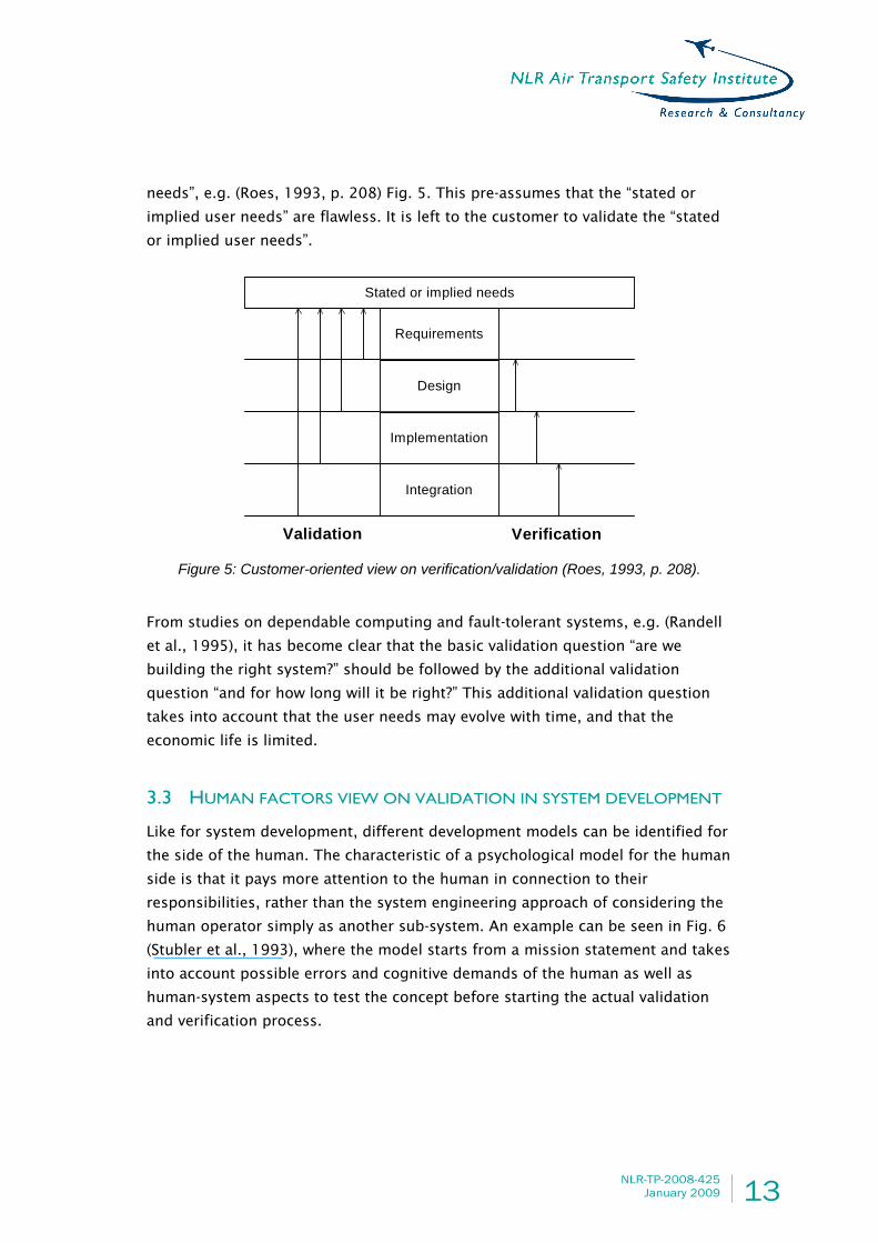
needs”, e.g. (Roes, 1993, p. 208) Fig. 5. This pre-assumes that the “stated or
implied user needs” are flawless. It is left to the customer to validate the “stated
or implied user needs”.
Validation Verification
Stated or implied needs
Requirements
Design
Implementation
Integration
Figure 5: Customer-oriented view on verification/validation (Roes, 1993, p. 208). From studies on dependable computing and fault-tolerant systems, e.g. (Randell
et al., 1995), it has become clear that the basic validation question “are we
building the right system?” should be followed by the additional validation
question “and for how long will it be right?” This additional validation question
takes into account that the user needs may evolve with time, and that the
economic life is limited.
3.3 HUMAN FACTORS VIEW ON VALIDATION IN SYSTEM DEVELOPMENT
Like for system development, different development models can be identified for
the side of the human. The characteristic of a psychological model for the human
side is that it pays more attention to the human in connection to their
responsibilities, rather than the system engineering approach of considering the
human operator simply as another sub-system. An example can be seen in Fig. 6
(Stubler et al., 1993), where the model starts from a mission statement and takes
into account possible errors and cognitive demands of the human as well as
human-system aspects to test the concept before starting the actual validation
and verification process.

14 NLR-TP-2008-425 January 2009
Mission statement
Performance req'nts:
- System
- Human
Functional req'nts:
- Individual M-MIS
features
- Integrated system
Individual / partially
integrated M-MIS
hardware prototypes
Integrated M-MIS
hardware prototype
M-MIS breadboard
designs
Part-task
simulators
Full-scope
simulator
Design process
Evaluation
Testbed
Concept testing Acceptance testing
Analysis of important operator
activities: Cognitive demands
and sources of error
Human factors / cognitive
science principles for
M-MIS design
Human factors / cognitive science
principles for analytical and
experimental evaluationsModel of human
performance
Research to guide
M-MIS concept
development
Studies to
Refine M-MIS
concepts
VerificationValidation
VerificationValidation
Figure 6: Development from human factors point of view (Stubler et al., 1993). M-MIS denotes man-machine interface system. There are other human development models, e.g. (Plant, 1993, p. 201; Westrum,
1993, p. 409; Jackson, 1989), which all have in common that the validation
question “are we building the right system?” is posed to a human factors expert
rather than a system designer. Similar as for system engineering, there are
multiple human factors interpretations of the validation question possible. For
example if we put the validation question both to a human factors designer of
human machine interfaces and to a developer of human centred automation
strategies, then we will get quite different answers. A good impression of the
large variety in human factors interpretations of validation can be found in Wise
et al. (1993).
3.4 BUSINESS MANAGEMENT VIEW ON VALIDATION
Usually the management of the lifecycle of a system is not an objective that
stands on its own. From a business need perspective the objective is rather to
best ensure market competitiveness through a cost-effective handling of all
elements and factors involved with the products under consideration (e.g.
customer satisfaction, continuous improvement, robust design, variability
reduction, statistical thinking, management responsibility, supplier integration,
quality control, education and worker training, teamwork, cultural change and
stakeholder interfaces). Basically it is a business need of improving the product
which makes it worthwhile to invest in a new system. Thus from a business need
perspective, the common validation question “are we building the right system?”
is only part of the more general validation question “are we designing and

NLR-TP-2008-425
January 2009 15
planning for the right product, and for how long?”. This generalised validation
question has two important implications:
1. Insufficient validation and verification during the early phases of a design of
a new production system may undermine a cost-effective lifecycle, since the
farther a production facility progressed in the design process, the more
costly the modifications will become since one change has all sorts of
implications that impose the need for yet other changes.
2. Validation and verification of a new production system does not stop when
production starts, but continues throughout the productive stage of its
lifecycle.
A well known approach in organizing these business-directed validation and
verification steps, both during development and operational phases, is known as
Total Quality Management (TQM). TQM realizes strategic management for quality
consciousness and assurance at four levels (Sage, 1992, p. 191):
• Inspected quality, to assess if performance satisfies pre-specified norms.
• Statistically controlled quality, using cost-effective performance metrics.
• Quality built-in through design and planning at operational task level.
• Proactively managed quality, through the involvement of all organizational
elements involved in the process and products under consideration.
All four levels ask for verification and validation steps. At the first three levels the
generalised validation question “are we designing and planning for the right
system?” is dealt with by the management only. At the fourth level, however, this
question is dealt with by all entities participating in the production. If the latter
level is being omitted, then we speak of Quality Management. Thus the
involvement of all entities at the fourth level is specific to TQM.
Implicitly, quality incorporates safety. Nevertheless, in safety related business
one sometimes refers to TQSM (Total Quality and Safety Management) in order to
clarify that safety consciousness and assurance should explicitly be incorporated
at the four levels identified:
• Inspected quality and safety, to assess if quality and safety satisfies pre-
specified norms.
• Statistically controlled quality and safety, using cost-effective performance
metrics.

16 NLR-TP-2008-425 January 2009
• Quality and safety built-in through design and planning at operational task
level.
• Proactively managed quality and safety, through the involvement of all
organizational elements involved in the process and products under
consideration.
A further elaboration of TQM has been done by EFQM (European Foundation of
Quality Management) and resulted in the EFQM (EFQM, 2002), which embeds the
principles of excellence in a framework that helps organizations assess their
capabilities and strengths in order to achieve their particular goals Fig. 7.
Leadership
People
Partnerships
& Resources
Processes
People Results
Society Results
Key
Performance
Results
ENABLERS RESULTS
INNOVATION AND LEARNING
Policy &
StrategyCustomer Results
Figure 7: EQFM model.
3.5 SAFETY MANAGEMENT AND MODERN SAFETY CASE
The safety validation of a safety-critical operation is documented in a Safety
Case, which is a series of documents describing the results of a safety validation
process. The Safety Case thinking has evolved in parallel with the safety
management and certification thinking. The original certification regime for an
operator of, e.g. an offshore petrochemical plant posed requirements to the
systems, procedures and crew, which were of a prescriptive nature. To put a new
or changed petrochemical plant into operation, the operator of that plant had to
build a Safety Case for approval by the national authorities. This Safety Case had
to provide the high level arguments and the supporting evidence that for each
normal and failure mode of that plant, the combination of frequency of
occurrence and severity of effects was acceptable.

NLR-TP-2008-425
January 2009 17
During the last two decades, the safety management and certification thinking
has rapidly evolved by positive experiences in safety-critical domains. It was the
report by Cullen (1990) on the Piper-Alpha accident of 1988 that made clear that
for complex safety critical operations in the petrochemical industry, there was a
need to introduce two major improvements: (1) replace the prescriptive
certification requirements by goal-setting ones (e.g. in terms of risk), and (2)
implement appropriate safety feedback loops at all management levels (Andlauer
et al., 1999). This goal-oriented safety management depicted in Fig. 8 shows that
goal setting is an iterative process in itself, even when restricting to a single
stakeholder. However, it does address the validation of actor requirements, i.e.
making sure that the identified actor requirements, wishes or needs are all
consistent with the goals of the design.
Set goals
Check against goals
Do to meet plan
Plan to meet goals
Feedback to "Set goals" and "Plan"
Figure 8: Goal-oriented Safety Management process.
Under a classical prescriptive regime, a Safety Case tends to provide an
instantaneous picture of the possible failure modes and their effects. Under a
modern goal-setting safety management regime, the scope of a Safety Case is
much wider: (1) it is aimed to cover anything that may influence safety, e.g. all
hazards but also all positive safety behaviours rather than failure modes only
(Fowler et al., 2007), and (2) it takes the impact of the safety management
approach of the responsible actors into account. Thus, a Modern Safety Case
incorporates the elements of a classical safety case, plus a description of the
safety management approach and a hazard register, see Fig. 9.

18 NLR-TP-2008-425 January 2009
Supportingevidence n
High levelargumentation
Safety assessment
Hazardsregister
Safetymanagement
Applicablestandards
The Operation
Supportingevidence 2
Supportingevidence 1
Figure 9: Modern Safety Case under goal-setting safety management.
A complementary development is that top level management has recognised the
Modern Safety Case as a valuable decision-support management tool during all
lifecycle stages of a safety critical operation (e.g. Short, 1998). For example,
during the conceptual development stage of a new safety critical operation, top
level management may have to make a decision with respect to further improving
the design first, or starting the preparation and procurement for the operational
implementation of a new or improved operation. In order to be fully informed,
top level management rather needs the complete picture provided by a Modern
Safety Case, than the partial picture provided by several technical evaluations. A
related development is that, for a safety-critical operation, insurance companies
reduce the insurance premium if a Modern Safety Case is available, e.g. in
petrochemical industry.
3.6 ANALYSIS OF SINGLE-STAKEHOLDER VALIDATION VIEWS
Finally, we analyse the established validation views presented in this section.
Here we start with the good news: these views are all well established for the
design of technical systems in aviation, and a lot of practical experience exists
with their application to a variety of problems. In particular, the Aerospace
Recommended Practices (ARP) of the Society of Automotive Engineers are
considered a standard for the development of civil airborne systems and
equipment (ARP 4754, ARP 4761). Each of the established validation views
highlights issues important for particular stakeholders.

NLR-TP-2008-425
January 2009 19
When considering validation of major changes in air transport operations, also
several questions can be posed regarding the established views. Below, these
questions are referred to as issues A-D:
A. Are multiple stakeholders addressed? There are many different stakeholders
involved in air transport operations; e.g., Airspace users, Human society,
Regulatory and supervisory authorities, Policy makers, Air Navigation Service
Providers, Airports, Manufacturers, Human operators, etc. Each of these
groups of stakeholders has its own goals, and each will have their influence
on future air transport operations. None of the established validation views
address the development process for more than one stakeholder.
B. Is integration with complementary views addressed? For major changes in air
transport operations, different validation aspects need to be addressed.
Safety aspects often require other validation perspectives than economy or
human factors aspects. These aspects should eventually be balanced and
integrated. For none of the established validation views it is explained how it
can be integrated with any of the other views. A related issue is that the
established validation views do not acknowledge the same phases in the
operation’s development lifecycle.
C. Is joint validation of multiple actors requirements addressed? The goal-
oriented safety management process described in Section 3.5 asked if the
requirements of an individual stakeholder are validated with respect to the
goal of this stakeholder. Due to the high complexity of air traffic
management and the multiple stakeholders vested interests, in practice it is
even more demanding to set joint goals for all stakeholders together, let
alone start with requirements that are validated against the joint goal setting.
None of the established views handle this.
D. Is the role of government policy makers taken into account? Government
forms a special stakeholder. In addition to being one of the stakeholders of
the previous issues A and C, it has a role as visionary policy maker for its
people. For major changes in air transport operations, the role of the policy
maker is of particular relevance due to the part they play as investors in
infrastructure and in coordinating with neighbouring countries. In some
situations (e.g. as in the Netherlands), the policy maker is also the national
regulator, who has a special additional role in major changes. None of the
established validation views addresses this; the only elements that are
arranged are the certifying authorities, but these have no role to play in the
economic judgement.

20 NLR-TP-2008-425 January 2009
4 MULTI-STAKEHOLDER VALIDATION VIEWS
This section presents some validation views from literature, which are considered
to go beyond the established ones, and analyses if they address the main open
issues A-D.
4.1 EUROPEAN OPERATIONAL CONCEPT VALIDATION METHODOLOGY
(E-OCVM)
A lack of clear and understandable information to support decision making on air
traffic management system implementation in the mid 1990s motivated
validation research in Europe. The project VAPORETO (Validation Process for
Overall Requirements in Air transport operations) (Blom et al., 1996) laid the
foundation: in this project, most of the established validation views of Section 3
were identified and several shortcomings were revealed. The European
Commission provided continuous support for addressing this (Fassert et al.,
1998) and brought together industry, research and development (R&D)
organisations, and service providers. From this point onwards, through a
sequence of other projects (e.g. CAVA, Concerted Action on Validation of Air
traffic management systems; MAEVA, Master Air traffic management European
Validation plan) the findings were eventually converged into the European
Operational Concept Validation Methodology (E-OCVM) (E-OCVM, 2007).
E-OCVM includes three aspects of validation that, when viewed together, help
provide structure to an iterative and incremental approach to concept
development and concept validation: (1) The Concept Lifecycle Model facilitates
the setting of appropriate validation objectives and the choice of evaluation
techniques, shows how concept validation interfaces with product development
and indicates where requirements should be determined; (2) The Structured
Planning Framework facilitates programme planning and transparency of the
whole process; (3) The Case-Based Approach integrates many evaluation exercise
results into key ‘cases’ (safety case, business case, environment case, human
factors case) that address stakeholder issues about air traffic management (ATM)
performance and behaviours. These three aspects fit together to form a process.
This process is focused on developing a concept towards an application while
demonstrating to key stakeholders how to achieve an end system that is fit for
purpose. The Concept Lifecycle is the central aspect of the validation process,
see Fig. 10. Note that the case based approach within E-OCVM is under further
development in (CAATS II, 2006).

NLR-TP-2008-425
January 2009 21
V1 V2 V3 V0 V4 V5
ATM needs Scope Feasibility Integration Pre-Operational Operational
ImplementationIndustrialisationand approval
Build,consolidate
and test
Iteratively develop andevaluate concept
Scope OperationalConcept and develop
Validation Plans
Gather and assessATM Performance
Needs
Focus of E-OCVM
Idea ImplementedConcept
Figure 10: E-OCVM Concept lifecycle model, from E-OCVM (2007). The six phases of the Concept Lifecycle Model are:
• V0 ATM Needs – The ATM performance needs and barriers must be
identified. The concept must show that it can alleviate these barriers enough
thus enhancing ATM performance to the anticipated required level.
• V1 Scope – The concept should be described in sufficient detail to enable
identification of the potential benefits mechanism. Unknown or unclear
aspects of the concept may exist as a number of options to be assessed
during the further validation process.
• V2 Feasibility – The concept is developed and explored until it can be
considered operationally feasible. During this phase, system prototypes will
be used that make assumptions about technical aspects in order to avoid
system engineering which can be costly and lengthy. Aspects that should be
focused on are operability and the acceptability of operational aspects.
Operational procedures and requirements should become stable and be
thoroughly tested.
• V3 Integration – Any required functionality is integrated into pre-industrial
prototypes, by using realistic scenarios that are representative of what the
concept must be able to manage. The focus is therefore on system level
behaviour, performance and establishment of standards/regulations
necessary to build and operate the required technical infrastructure.
• V4 Pre-Operational – Pre-operational prototypes will be transformed into
industrial products ready for implementation and all institutional issues
concerned with procedures approval should be addressed.
• V5 Implementation – This is the phase when products and procedures are
combined to create an operational system.
E-OCVM (2007) integrates several complementary established validation views
(issue B in Section 3.6). In particular, it addresses multiple validation aspects by

22 NLR-TP-2008-425 January 2009
combining three different approaches, i.e. (1) The concept lifecycle model, (2) the
structured planning framework, and (3) the case-based approach. In addition, it
identifies the need to integrate views within these approaches, e.g. from safety
case, business case, environment case, human factors case, etc. Regarding the
issue of multiple stakeholder roles (issue A in Section 3.6), the E-OCVM explicitly
includes steps that identify the multiple stakeholders involved, and that identify
the objectives and needs of each of the stakeholders. Subsequently, it uses the
requirements of the individual stakeholders to develop a validation strategy,
which is regularly reviewed and updated. E-OCVM however does not explicitly
address how the requirements of different stakeholders are being balanced and
does not explicitly address the joint validation of stakeholder requirements
(issue C); implicitly it is expected that regular reviews and updates would be
sufficient. Policy makers (issue D) are implicitly addressed as one of the
stakeholders involved, but their special role as investors in infrastructure is not
explicitly addressed.
Summarising, the E-OCVM is particularly strong at addressing issue B, although
parts of it are under development (particularly for safety and for human factors).
Issue A is also addressed, but the coverage of issues C and D is not clear.
4.2 INTEGRATION FRAMEWORK IN COMPLEX SYSTEMS ENGINEERING
DESIGN
In order to integrate safety in the design and construct of major projects (Stoop,
2005) develops a new notion of systems engineering design and system
architecture, which consists of three principal elements: (DCP). These elements
can be interrelated along three dimensions: (1) a systems dimension, (2) a
lifecycle dimension and (3) a design dimension. Together they constitute an
integrated systems architecture prototype: the DCP diagram, Fig. 11.

NLR-TP-2008-425
January 2009 23
The DCP diagramDesign Control
Life-cycle: coordination
design development construction operation modification
MACRO
MESO
MICRO
Practice
Systems-level:
integration
Design: innovation
Copyright: J.A. Stoop, 1996
GOAL
FUNCTION
FORM
Figure 11: Systems architecture model: The DCP diagram, from Stoop (2005).
The systems dimension defines three levels: the Micro level of the user/operator,
the Meso level of stakeholders’ organisation and operational control, and the
Macro level of institutional conditions, i.e. the interactions between stakeholders’
organisations and operational control. At this dimension the issue of integration
of administrative and emergency organisation across the various levels is crucial.
The lifecycle dimension defines a series of subsequent phases, being design,
development, construction, operation and modification. At this dimension, the
coordination of decision making among actors across the phases is crucial.
The design dimension identifies three principal phases in design, being goal
(expressed by a program of requirements, concepts and principles), function
(expressed by design alternatives) and form (expressed by detailed design
complying with standards and norms). At this dimension, the potential of
technical innovation for new safety solutions is crucial.
The DCP model addresses the integration of complementary views (issue B in
Section 3.6) by the inclusion of the levels Macro, Meso and Micro. In addition, the
three DCP dimensions can be regarded as three complementary views, which are
being coupled in one DCP diagram. Requirements joint validation (issue C) is
addressed by the inclusion of and checking against “goal” at the Macro level.
Multiple stakeholder roles (issue A) are addressed across all three DCP
dimensions, starting during the Macro phase, and maintained later on. Policy

24 NLR-TP-2008-425 January 2009
makers (issue D) are addressed as one of the stakeholders, but their special role
is not explicitly acknowledged.
Summarising: the DCP model addresses issues A, B, and C. Its strength is in
identifying a Macro phase coupled to stakeholder joint goal setting at an early
stage of the concept lifecycle.
4.3 JOINT GOAL-ORIENTED SAFETY MANAGEMENT
The introduction of goal-oriented safety management thinking by airlines,
airports and ATM service providers may easily create an increasing tension
between individual actors due to the desired evolution in goal-settings and
operational solutions. In order not to jeopardise the valuable world-wide
standardisation process, airlines, airports and ATM service providers should also
be actively involved in the harmonised evolution of both individual and joint
actor’s goals at the national, regional and international levels. This leads to an
extension of the goal-oriented safety management to a Joint goal oriented safety
management (Blom and Nijhuis, 2000), and is depicted in Fig. 12.
Set actor goals
C h eck again stactor /join t goals
D o to m eet p lan
Plan to m eet goals
Feedback to "A gree", "Set" an d "Plan "
A gree join t goalsettin gs
Figure 12: Integration of Safety Management processes in air transport is enabled by goal-setting co-ordination at national, regional and international levels, and by the exchange between collaborating actors of adequate safety feedback at all management levels (Blom and Nijhuis, 2000).
The co-ordination between air transport operation directed stakeholders often
starts at a national level and involves policy makers, regulators, airlines, airports
and ATM service providers. The same variety of actors should also be involved at
the regional and international levels, since pilots from various countries have to
collaborate with controllers all over the world. The airlines, airports and ATM

NLR-TP-2008-425
January 2009 25
service providers should collaborate on the joint identification of their actor
goals under various operational concepts and against jointly elaborated high
level objectives for various air transport demands and environments.
Because the various stakeholders of the novel operational concept to be
developed are all collaborating, a modern Safety Case per stakeholder does not
suffice anymore. There also is need of a Joint Safety Case that should be
produced with proper collaboration of all stakeholders (Blom and Nijhuis, 2000;
Blom et al., 2000). As has been well explained in Hollnagel and Woods (2005)
and Hollnagel et al. (2006), this should take into account organisational and joint
cognitive systems aspects that influence safety of the operation.
The Joint goal oriented safety management model addresses requirements joint
validation (issue C in Section 3.6) by explicitly identifying the goal setting level
plus feedback to it from check against joint goals. Multiple stakeholder roles
(issue A) are addressed by means of the joint actors goal setting level plus
feedback to it from check against joint goals. Policy makers (issue D) are only
implicitly included as one of the stakeholders. The model does not explicitly
integrate complementary views (issue B).
Summarising, the Joint goal oriented safety management model addresses issues
A and C. Its particular strength is in the step that the stakeholders need to
develop their joint goal, which is updated after feedback from other steps.
4.4 MULTI-STAKEHOLDER SAFETY MANAGEMENT
Following a recommendation in RAND (1993), an initial multi-stakeholder safety
management approach has been established in 1995 by the Netherlands air
transport sector. Recently, this platform of and for the sector to improve air
transport safety (ground and flight safety) at and around Amsterdam airport
structurally and collectively has been further improved (VpS ToR, 2006). The
activities of this platform are aimed at the interfaces between business processes
of the sector parties at the airside. Safety at these interfaces is seen as collective
responsibility of the sector and as boundary condition for optimal and safe
airport operations. Membership of this platform is mandatory for all businesses
that execute safety-critical activities at Amsterdam airport. This is laid down in a
‘Transactions Regulation’, which also commits members to have a form of Safety
Management System, aimed at jointly managing safety (i.e. quality, risk, and
incidents).

26 NLR-TP-2008-425 January 2009
This multi-stakeholder safety management platform explicitly addresses multiple
stakeholders roles (issue A in Section 3.6). The role of policy makers (issue D) is
addressed implicitly. However, the platform addresses the operational phase
only, not the design phase, hence the platform neither integrates complementary
validation views (issue B) nor addresses requirements joint validation (issue C).
Summarising, the Multi-stakeholder safety management model addresses issues
A and D. Its strength is that it gives a particular view to the joint goal setting step
of the Joint goal-oriented safety management model in Section 4.3, which makes
it less generic.
4.5 ROLES OF GOVERNMENT
A picture that shows involvement of multiple stakeholder groups, including the
government, as part of risk management is given in Rasmussen and Svedung
(2000), see Fig. 13. It shows that there are close links and many nested levels of
decision-making involved in risk management and regulatory rule-making to
control hazardous processes. The challenge to a safety validation framework is
to take all these issues into account in an integrated way.
Political Science;
Law; Economics;Sociology
Economics;
Decision Theory;
OrganizationalSociology
Industrial
Engineering;
Management &
Organization
Psychology;
Human factors;
Human-Machine
Interaction
Mechanical,
Chemical and
Electrical
Engineering
Public
Opinion
Safety reviews,
Accident
Analysis
Laws
Judge-
ment
Regulations
Judge-
ment
Judge-
ment
Judge-
ment
Judge-
ment
Company
Policy
Plans
Action
Incident
Reports
Operation
Reviews
Logs &
W ork Reports
Observations,
Data
Hazardous process
Work
Staff
Management
Company
Regulators,Associations
Government Environmental Stressors
Changing political
climate and
public awareness
Changing market
conditions andfinancial pressure
Changing
competency
and levels
of education
Fast pace of
technological
change
Research discipline
Figure 13: This figure from Rasmussen and Svedung (2000) shows how many nested levels of decision-making are involved in risk management and regulatory rule making to control hazardous processes. This social organization is subject to severe environmental pressure in a dynamic, competitive society. Low risk operation depends on proper co-ordination of decision making at all levels. However, each of the levels are often studied separately within different academic disciplines.

NLR-TP-2008-425
January 2009 27
In the two models of Fig. 14, the government (ministries and national supervisory
authority) is included in two different ways. The dashed box denotes a Project
Development Office, which is made responsible for developing a novel
operational concept and a corresponding Safety Case. The Safety Case is judged
by the national supervisory authority. In the model on the left-hand-side, a
Ministry directs a Project Development Office towards the commercial
stakeholders. This Project Development Office acts as a commissioner/client on
behalf of the Ministry; process integration is central. In the model on the right-
hand side, the Project Development Office sits around the commercial
stakeholders.
Commercial
Stakeholders
NSAMinistries
Project
Development
Office
Commercial
Stakeholders
Ministries NSA
Project
Development
Office
Figure 14: Two models of possible government involvement in combination with a project development office.
Variations of these models are possible, e.g. by taking into account a special role
for an air navigation service provider as an independent governing body that is
responsible for its own tasks, but that can also be regarded as part of the
government. This represents the situation of the air navigation service provider
in the Netherlands.
The three models presented above address the role of policy makers (issue D in
Section 3.6), and to some extent the issue of multiple stakeholder roles (issue A),
but neither the integration of complementary views (issue B) nor the joint
validation of requirements (issue C).
Summarising, these models address issues A and D only.

28 NLR-TP-2008-425 January 2009
4.6 SUMMARY AND USE OF STRONG POINTS OF THE VALIDATION
MODELS IDENTIFIED
Table 1 summarises whether the various models identified in this section give
support to cover the issues A-D, for which none of the established validation
views provides a good coverage during development process. In all cases, “Yes”
means that this model addresses the issue; this does not imply a judgement of
the extent to which the issue is addressed. An underlined Yes denotes which
model addresses the issue best with emphasis on the early concept life cycle
phases.
Table 1: Support to coverage of open issues by models identified in Section 4. Yes denotes the issue is addressed; an underlined Yes denotes which model addresses the issue best; – denotes not addressed
A B C D Multiple
stakeholders roles
Integrating complementary
views
Requirements joint
validation
Role of policy
makers
E-OCVM Yes Yes – –
DCP model Yes Yes Yes –
Joint goal-oriented safety management Yes – Yes –
Multi-stakeholder safety management Yes – – Yes
Roles of Government Yes – – Yes
Table 1 shows that Issue A (multiple stakeholders roles) is addressed to some
extent by all five models. However, when it comes to balancing the roles of these
stakeholders, coverage is implicit for E-OCVM, Multi-stakeholder safety
management, and Roles of government. Issue B (the integration of
complementary views) is addressed by both E-OCVM and the DCP model. E-OCVM
stands out by integrating different cases for various key areas, although these
approaches are still under development. The DCP model and the Joint goal-
oriented safety management model clearly acknowledge the need to bring
stakeholders together in balancing their goals and roles from an early stage,
issue C. The latter emphasises the role of providing assessment feedback to the
stakeholders. Finally, issue D (the role of policy makers) is addressed best by the
Roles of government models and to some extent by Multi-stakeholder safety
management, although the other models do implicitly acknowledge policy
makers as one of the stakeholders. This opens the door for the government to
additionally play a part in bringing the stakeholders together and encourage the
joint goal setting.

NLR-TP-2008-425
January 2009 29
5 INTEGRATION INTO SAFETY VALIDATION
FRAMEWORK
The aim of this section is to integrate the strong points of the established and
novel validation views analysed in the previous sections. The integrated safety
validation framework first addresses the Macro phase of an operation, during
which multiple stakeholder roles need to be balanced, and in which a CONOPS
(concept of operations) is agreed on (at some high level) by all stakeholders. In
this Macro stage, the integration of validation views focuses on the multi-
stakeholder views of Section 4. Next, during the Meso and Micro phases, detailed
operational scenarios describing procedures, working practices and system
specifications will have to be developed to enable CONOPS implementation. In
these Meso and Micro phases, the established validation views come in focus.
Fig. 15 shows that the Macro phase roughly corresponds with phases V0-V3 of
the E-OCVM, and the Meso phase runs from V4.
V1 V2 V3 V0 V4 V5
Needs Scope Feasibility Integration Pre-Operational Operational
MACRO MESO Figure 15: Coupling of phases V0-V5 to phases Macro and Meso.
5.1 APPROACH TO COMBINING STRONG POINTS OF VALIDATION
VIEWS
Section 4.6 showed that when it comes to insight into the extent to which
multiple stakeholders need to balance their roles (issue A in Section 3.6), the
DCP model provides the best view. The DCP’s systems dimension (vertical axis)
defines three levels: Macro (institutional conditions), Meso (organisation and
operational control) and Micro (user/operator). The need to jointly balance
stakeholder roles is largest at the Macro level. At the design dimension (diagonal
axis) in the DCP model, the Macro level is coupled to a Joint Goal setting, which
provides the link with issues A and C in Section 3.6, which is explained further

30 NLR-TP-2008-425 January 2009
below. Hence in order to address these issues A and C, we need to particularly
focus on the Macro level first.
The lifecycle dimension (horizontal axis) of the DCP model is also adopted by the
E-OCVM, hence this will be another important dimension to cover. However, it
appears that the lifecycle phases in the E-OCVM and the phases in the DCP model
are not aligned. In order to make effective use of European standardisation
developments, the best option appears to be to adopt the phases of the E-OCVM
concept lifecycle view.
A closer look reveals that the Macro phase of the DCP covers roughly lifecycle
phases V0 through V3 of the E-OCVM. The follow-up lifecycle Meso phase of DCP
covers roughly lifecycle phases V4 and V5, see Fig. 15. A key output of the Macro
phase consists of jointly validated requirements for different stakeholder types
as input to the Meso phase.
Section 4 also showed that Requirements joint validation (issue C in Section 3.6)
is addressed by two of the models, i.e. DCP model and Joint goal-oriented safety
management. A key common aspect of these models is that stakeholder joint
goal-setting takes place at an early stage in concept design. In addition,
regarding the multiple stakeholder roles (issue A), the DCP model and the Joint
goal-oriented safety management model clearly acknowledge the need to bring
stakeholders together and balance their goals and roles from an early stage. In
particular for safety, at the Macro level, the Joint goal-oriented safety
management view provides four types of activities:
(1). ‘Joint goal setting’,
(2). ‘Plan’ (CONOPS development),
(3). ‘Do’ (what does this mean per stakeholder), and
(4). ‘Check’ (validation).
This reveals that there are four main processes to consider, which are referred to
as Joint Goal setting, CONOPS development, Stakeholder allocations, and Joint
safety validation, see Fig. 16. Obviously, as depicted in Fig. 16, several
interactions exist between these four processes. In addition, as shown above,
since CONOPS development will be conducted in several lifecycle phases, each of
these four main processes will have to be synchronised with such lifecycle
phases and with each other. In particular, as argued above, these phases are to
be in line with the E-OCVM concept lifecycle view, which consists of six phases
V0 through V5. The synchronisation compares and integrates the results of the
four main processes in each phase, so that an effective start is made with the
next phase.

NLR-TP-2008-425
January 2009 31
At the Meso phase, which starts around lifecycle phase V3-V4 (see Fig. 15), the
Joint goal setting and the Stakeholder allocation processes become of a more
passive nature, and the CONOPS development and Safety validations are conducted
at the level of individual stakeholders. Therefore, in this phase, the established
validation views of Section 3, i.e. the V-model, the Spiral model, etc., are of
particular use. These established views take the jointly validated requirements
developed in the Macro phase as a starting point and develop a more detailed
design of the operation. It is noted that if the Meso phase starts too early, then
the requirements that come out of the Macro phase may not have converged yet.
The E-OCVM also provides support to the integration with other assessments
(issue B in Section 3.6), by means of its link between the Safety validation
process and all non-safety validations (Economy, Environment, etc). It is noted
that for the earlier phases this support is still under development.
Note that for a proper balancing of stakeholder joint goals at the Macro level we
need to structure by means of a joint entity, which we refer to as Project
Development Office (see dashed box in roles of government views, Section 4.4).
This means that a Multi-actor safety management organisation like the one
described in Section 4.3 should extend its scope and activities to the pre-
operational lifecycle phases. This addresses issue D in Section 3.6.
Joint Goal
settings
Stakeholder
allocations
CONOPS
development
Joint
safety
validation
Figure 16: SAFMAC proposed safety validation framework, in which four main ‘processes’ Joint Goal setting, CONOPS development, Joint safety validation, and Stakeholder allocations are elaborated through a spiral development approach.

32 NLR-TP-2008-425 January 2009
The following subsections outline the four major processes depicted in Fig. 16 in
more detail.
5.2 JOINT GOAL SETTING
The development of major changes in air transport operations comprises a
complex and lengthy process managed by international organisations, such as
ICAO, that require agreement by a significant number of parties at the
international level. These major changes do not form an issue that European
regulators and air navigation service providers can attempt in isolation, and they
will require significant international co-ordination and co-operation. In addition,
each of the stakeholders will have their own requirements, wishes and needs,
which can be formulated as goals. The process of obtaining consensus about the
joint goals of the different stakeholders will be a driver of the major change in air
transport operations, and will be described here as a goal setting process. To
accomplish this, the problem can be decomposed into a hierarchy of sub-
problems each of which could be analysed without the need to solve the next
sub-problem. The solution of each of these sub-problems can only be addressed
through an explicit involvement of experts in advanced operational concepts and
safety experts. A general goal setting process starts with the identification of a
high-level goal, after which this high-level goal is further specified into elements
that explain what the high-level goal means for the different actors involved.
5.3 CONOPS DEVELOPMENT
The CONOPS development phases will be based on general practices of CONOPS
development by major European players in the field, and should fit with the Joint
Goal setting phases of the previous subsection. The phases of the CONOPS
development process associated to major changes in air transport operations
should be in line with the E-OCVM concept lifecycle view. The phases that fall in
the Macro view identify the reasons for initiating the required changes to the
operational concept as well as the evidence that the initial concept makes sense
for all parties involved. The potential solutions and their enablers and/or
concepts have been identified. The potential solutions identified are combined to
form a high-level CONOPS.
During the CONOPS development process new insights are inevitable and may
result in changing operational environment or alternative solutions, which in turn
may lead to small or large modifications of the way the concept is organised. The
development process as a whole is therefore highly iterative.

NLR-TP-2008-425
January 2009 33
5.4 JOINT SAFETY VALIDATION
Airlines provide safety critical services directly to their passengers and thus to
human society. For the safety of their flights, airlines critically depend of services
by other service providers, such as air navigation service providers and airports.
Whereas a Modern Safety Case is built by individual service providers, a Joint
Safety Case is built by collaborating stakeholders. The Joint Safety Case should
provide the high level argumentation and evidence for the total operation, while
each Modern Safety Case should provide the evidence and the high level
argumentation for that part of the operation that falls under the responsibility of
one specific service provider. For the Joint Safety Case there are multiple
approaches to setting up a useful high level argumentation. Three hypothetical
approaches are:
• Hierarchical approach, in which the Joint Safety Case is being built first. On
the basis of such a Joint Safety Case, the requirements to be fulfilled by each
of the stakeholders involved can be identified. Subsequently, each of these
stakeholders has to develop a Modern Safety Case to show that the
requirements, posed by the Joint Safety Case on his own operation, are
satisfied.
• Negotiation approach, in which a Joint Safety Case and generic versions of
Modern Safety Cases are being built in parallel in a spiral development
process, and with proper exchange between the two processes. If there are
gaps and/or overlap between the various resulting generic Modern Safety
Cases and the Joint Safety Case, then through negotiations between the
collaborating stakeholders adequate improvements should be identified.
• Integration approach. This approach means that the generic Modern Safety
Cases are being built first. Next, a Joint Safety Case is being built through
integration of the material available from the generic Modern Safety Cases.
The problem with this approach is that risky combinations of hazards do not
show up in an early phase, and that it easily leads to a Babylonia building.
The hierarchical approach is in theory the preferred one but the negotiation
approach may be more practical. Because there is little experience in developing
a Joint Safety Case, the best practice remains to be developed. Obviously, it is up
to the collaborating stakeholders to choose the approach that is judged to be
most effective in realising their collaboration objective. The implications of the
Joint Safety Case considering the complete operation, including all commercial
actors involved, can best be explained in terms of the Modern Safety Case
contents as depicted in Fig. 9:

34 NLR-TP-2008-425 January 2009
The operation: The Joint Safety Case considers the total operation, while each
Modern Safety Case considers that part of an operation that concerns a particular
actor only. This implicitly means that Modern Safety Cases often go into more
detail than the Joint Safety Case, while the Joint Safety Case should explicitly
cover issues like responsibilities and accountabilities of the various stakeholders,
including the interfaces/boundaries between them. In order to prevent any
confusion, in particular for hazardous situations, it is necessary that all Safety
Cases refer to the same description of the advanced operation.
Applicable standards: A Joint Safety Case should maintain a joint listing of all
applicable (international and national) standards, while each Modern Safety Case
should receive a copy of this, and should contribute to the completion of the
joint listing.
Safety Management: Each Modern Safety Case relies on the Safety Management of
its responsible stakeholder. A Joint Safety Case relies on how Safety Management
responsibility and co-ordination is arranged for the total operation under
consideration.
Hazards register: Since hazards that start under the responsibility of one
stakeholder often affect the operation of another stakeholder, it is very important
that a Joint Safety Case makes a joint hazard register which is as complete as is
possible, while each Modern Safety Case has a copy of this joint hazard register.
This also means that hazard identification and development of safety
improvement measures per hazard should be done both at the level of a Joint
Safety Case, and at the level of each Modern Safety Case.
Safety assessment: The Joint Safety Case should assess the safety of the
complete operation, while each Modern Safety Case should assess the safety of
that part of the operation that falls under the responsibility of the particular
stakeholder. In effect this often means that within a Joint Safety Case it is
necessary to perform a safety assessment for the operation, while within a
Modern Safety Case the aim is to perform a safety assessment for the
contribution by a single stakeholder. Any assumptions about the operation that
have been made during the assessment should be clearly stated and justified;
however obvious these assumptions may be, the implications for others involved
with the project cannot always be predicted.
Supporting evidence: A Modern Safety Case may provide safety supporting
evidence for the Joint Safety Case. A Joint Safety Case, however, may only provide

NLR-TP-2008-425
January 2009 35
supporting evidence for a Modern Safety Case if it is shown that this does not
lead to a vicious circle. For procured equipment, a manufacturer’s Safety Case
may form supporting evidence both for a Modern Safety Case and for a Joint
Safety Case.
Similar as applies to a Modern Safety Case, a Joint Safety Case must be developed
in a way that allows for modifications, extensions or revisions, making them
living documents that can be updated when, for example, new hazards have
been identified and assessed during the development of the new or changed
operation.
5.5 STAKEHOLDER ALLOCATIONS
At each phase of the development of a CONOPS, it is essential to have a translation
of what the development means for the individual stakeholders, in order to get
their involvement and approval at an early stage. Here, the Macro phase (roughly
from V0 to V3) provides requirements for stakeholders, which are to be used as a
starting point for the Meso phase (from V4 onwards). In fact, this comes down to
an allocation per phase of responsibilities, functionalities, information flows and
system functions of the future concept per individual stakeholder, in addition to
an allocation of safety validation activities. This allocation should stimulate an
early start of the development work at Meso level by each of the stakeholders. At
the Meso level (i.e. from phase V4 onwards), a CONOPS description needs to be
worked out in more detail.
6 ELABORATION OF SAFMAC FRAMEWORK
PROCESSES
The final step is to couple the four ‘processes’ outlined in the previous
subsections, through a spiral development approach, so that they form one
framework process along the E-OCVM phases V0 through V5 (Section 4.1). In
addition to the synchronisation after each phase that should take place, there are
boundary conditions, e.g. foreign influences, and other influences, like those
from government/regulator. But although there may also be several iterations
across the different phases, there is a red thread that runs through the first
phases (in parallel or in an undecided order) of the four processes Joint goal
setting, CONOPS development, Joint safety validation, and Stakeholder allocations,

36 NLR-TP-2008-425 January 2009
after which a synchronisation takes place, and after which the red thread
proceeds with the next phase of Joint goals setting, CONOPS development, etc.
In Tables 2–5, the four processes are outlined for E-OCVM phases V0-V3, which
focus on the Macro phases. For phases V4, V5 and beyond, the established
validation views provide further detail.
Table 2 Joint goal setting in phases V0-V3
Phase Joint goal setting V0 – Needs
The high-level joint goal is identified, including boundary conditions. The high-level joint goal should at least discuss goals for the ICAO Key Performance Areas from ICAO (ICAO Doc 9854)
V1 – Scope
The high-level joint goal is further detailed and specified to direct a CONOPS development that takes place in this phase, or where necessary corrected. This includes at least identification of requirements, of the roles of the human actors, and of the technology needs.
V2 – Feasibility
The high-level joint goal is further detailed and specified to direct a CONOPS development that takes place in this phase.
V3 – Integration
The agreed joint goals are revisited and verified, and where necessary further detailed, adapted or corrected, and next agreed upon.
Table 3: Table 3: CONOPS development in phases V0-V3
Phase CONOPS development V0 – Needs
The barriers in reaching the high-level joint goal are identified. To complete the validation of the concept in later phases, the concept must show that it can alleviate these barriers enough thus enhancing performance to the anticipated required level. Also, the operational environment is determined.
V1 – Scope
The concept is described in sufficient detail to enable identification of the potential benefits mechanism (i.e. the change to systems and/or operations that will enable a known barrier to be alleviated). Some aspects of the concept will be unknown or unclear at this stage. They may exist as a number of options to be assessed during the further validation process. This stage should lead to one or more High-Level CONOPSes, which can be further analyzed and refined later.
V2 – Feasibility
The concept is developed and explored until it can be considered operationally feasible. Prototypes will be used that make assumptions about technical aspects in order to avoid system engineering which can be costly and lengthy. Aspects that are focused on are operability and the acceptability of operational aspects. Operational procedures and requirements become stable. HMI, Operating procedures (for normal and key non-normal conditions) and phraseology become clear.
V3 – Integration
The concept is further developed, enabling identifying in more detail the performance in the concept of operation. Stakeholders further develop their part of the operation as part of their stakeholder allocations, without losing the view on the integrated operation. Required functionality is integrated into pre-industrial prototypes. Engineering processes are explored to provide experience that will be useful to building the end-system. Realistic scenarios that are representative of what the concept must be able to manage in the target end-system. The focus is on system level behaviour,

NLR-TP-2008-425
January 2009 37
performance and establishment of standards/regulations necessary to build and operate the required technical infrastructure.
Table 4 Joint safety validation in phases V0-V3
Phase Joint safety validation V0 – Needs
In this phase the high-level joint goal and the barriers need to be understood. For safety validation, this means that the safety aspects of the high-level joint goal and barriers must be understood. Thus, it is investigated what the goal is with respect to safety, and what the applicable safety regulations and safety criteria are. Furthermore, it is analyzed whether the current operation meets the goal, and if it does not, why this is not the case.
V1 – Scope
In this phase potentially many concept ideas are identified in the CONOPS development process. Only the most promising of those ideas should be further developed. The ideas are still described on a high-level. For safety validation, this means that involvement should be focused on giving feedback on which ideas are most promising from a safety point-of-view. This is best done by analyzing the concept ideas, and feeding back to the CONOPS development the main safety issues with respect to each concept idea.
V2 – Feasibility
In this phase it is to be analyzed whether the concept is feasible. For safety validation this means that one should become reasonably sure that all risks of the concept are tolerable with respect to the joint goal and thus the safety criteria selected. Hence, all risks should be identified and assessed, and realistic (attainable) risk mitigations should be identified which should ensure the risk to stay tolerable. After this step, it should be reasonably sure that the concept can be implemented safely. More detailed justification may follow later however. To evaluate the feasibility of the concept, the full scope of the concept should be considered, and hence all stakeholders should agree on their part of a CONOPS, and the performance of their part.
V3 – Integration
In this phase, a more detailed concept comes available, and more evidence is gathered for the performance of the integrated concept. For safety validation the risk mitigations are validated: evidence is gathered that they are indeed sufficient to have a concept that complies with the need and safety criteria, and it is analyzed whether the risk mitigations are indeed achievable.
Table 5: Stakeholder allocations in phases V0-V3
Phase Stakeholder allocations V0 – Needs
The individual performance needs and barriers per stakeholder are identified, and if needed corrected.
V1 – Scope
The concept that enables identification of the potential benefits mechanism is translated to what this means to the individual stakeholders in order to get their approval and involvement at an early stage. This may include identification of potential sub-solutions, and eventually lead to a sub High-Level CONOPS (that is, the stakeholder-specific part of the High-Level CONOPS).
V2 – Feasibility
The feasible CONOPS is translated to what this means to the individual stakeholders in order to get their approval and involvement at an early stage.

38 NLR-TP-2008-425 January 2009
V3 – Integration
The agreed stakeholder allocations take place, and it is verified whether they constitute a CONOPS developed in V3. Where necessary, the stakeholder allocations are further detailed, adapted or corrected, and agreed upon.
It should be noted that synchronization of the four major processes does not
need to be restricted to the moments on which a phase of the Concept Lifecycle
Model ends and may be recommendable within certain phases. In addition, the
phases described above are expected to have potential for further improvements
due to increasing experiences in safety validation. In the early phases of the
development of an advanced operational concept, the SAFMAC main processes
joint goal setting, stakeholder allocation, and joint safety validation have an
active character: the joint goal is further specified, each time new stakeholder
allocations are agreed upon, and the safety validation activities are further
deepened. Once an operationally feasible CONOPS has been developed, validated
and agreed upon, including stakeholder allocations, it could be sufficient to
revisit the joint goal, the stakeholder allocations and the safety validation, to
check whether everything is still correct, in place, and in coherence. Here, the
character of these three processes may become more passive.
7 CONCLUDING REMARKS
The aim of this paper was to study the needs for safety validation of multi-
stakeholder changes in air transport operations, i.e. changes which particularly
require the balancing of the roles and responsibilities of multiple stakeholders.
Through a process of analysis, evaluation, review and consolidation, including an
alignment with important European developments in the field (specifically E-
OCVM), this paper developed a safety validation framework that consists of four
processes: Joint goal setting by all stakeholders; CONOPS development; Joint safety
validation process; Allocation of responsibilities and requirements (possibly
including functionalities and information flow developments and validation
responsibilities), to appropriate individual stakeholders. The framework is
referred to as SAFMAC (SAFety validation of MAjor Changes).
In order to further these results, the SAFMAC developments will be focused along
two tracks: a policy track, and a follow-up study track. The policy track aims for
obtaining further acceptance, nationally, within Europe, within the USA, and
within ICAO.
The main issues to be addressed in the follow-up study track are:

NLR-TP-2008-425
January 2009 39
• Further clarifying the roles and responsibilities of the different stakeholders
within the process of developing a safety validated CONOPS. In particular,
attention should be paid to the role of the regulator and the supervisory
authorities, including the need for missing regulations.
• Development of a set of safety validation quality indicators (Everdij and Blom,
2007).
• Embedding of safety methods (see e.g. Safety Methods Database (2008)), into
the safety validation process, and further development of safety validation
process, including mapping to the individual stakeholders.
• Application of the framework to one or more interesting (national) major
changes in air transport operations.
A first national application has been started for a project on merging civil and
military airspace management. The early experience in this project already shows
that thinking about joint goal setting works remarkably refreshingly for the
participating stakeholders and causes them to look beyond their own familiar
contexts.
Ongoing developments regarding the identified validation views and newly
emerging validation views will be considered in the further SAFMAC development
as well.
ACKNOWLEDGEMENTS
The authors thank a Supervision group, consisting of representatives of
Eurocontrol, Directorate-General Civil Aviation and Maritime Affairs, ATC the
Netherlands, Inspectorate Transport and Water Management, and Kindunos, for
their review comments and suggestions during the study, Dr. John Stoop (Delft
University of Technology) for reviewing a draft of this paper, and anonymous
reviewers for valuable comments.

40 NLR-TP-2008-425 January 2009
8 REFERENCES
Andlauer, E., Chenevier, E., Gaudiere, G., Girard, F., Hudson, P., 1999. ARIBA
WP3, Analysis of the ATM certification problem. <http://www.aribaproject.org/>.
ARP 4754, 1995. Certification considerations for highly-integrated or complex
aircraft systems, Systems Integration Requirements Task Group AS-1C, Avionics
Systems Division (ASD), Society of Automotive Engineers, Inc. (SAE).
ARP 4761, 1994. Guidelines and methods for conducting the safety assessment
process on civil airborne systems and equipment, S-18 Committee, Society of
Automotive Engineers, Inc. (SAE).
Blom, H.A.P., Hendriks, C.F.W., Nijhuis, H.B., 1996. VAPORETO, VAlidation
Process for Overall REquirements in air transport operations, WP3: Assess
necessary validation developments, work package report, issue 2.1, 17 January
1996, NLR CR 95524 L.
Blom, H.A.P., Nijhuis, H.B., 2000. ARIBA WP6, Consolidation of results for safety
certification in ATM, Part I: Safety certification framework in ATM, NLR-TR-99576.
<http://www.aribaproject.org/>.
Blom, H.A.P., Everdij, M.H.C., Daams, J., 2000. ARIBA WP6, Consolidation of
results for safety certification in ATM, Part II: Safety Cases for a new ATM
operation, NLR-TR-99587, <http://www.aribaproject.org/>.
CAATS II, 2006. Project website. <http://www.caats2.isdefe.es/index.htm>.
Cullen, The Lord, 1990. Report on Piper Alpha accident, HMSO, London.
Deutsch, M.S., 1982. Software Verification and Validation, Prentice-Hall.
E-OCVM, 2007. Eurocontrol EATMP, European Operational Concept Validation
Methodology, version 2.0, 17 March 2007.
EQFM, 2002. Brochure at <http://www.efqm.org>.
Everdij, M.H.C., Blom, H.A.P., Nollet, J.W., Kraan, M.A., 2006. Need for novel
approach in aviation safety validation. In: 2nd Eurocontrol Safety R&D Seminar,
October 2006, Barcelona, Spain.
Everdij, M.H.C., Blom, H.A.P., 2007. Study of the quality of safety assessment
methodology in air transport. In: Ann G. Boyer, Norman J. Gauthier (Eds.),
Proceedings of the 25th International System Safety Conference, Engineering a
Safer World, Hosted by the System Safety Society, Baltimore, Maryland USA, 13-
17 August 2007, pp. 25-35.

NLR-TP-2008-425
January 2009 41
Fassert, C., Chenevier, E., Laval, V., Girard, F., Blanker, P.J.G., Van Eenige, M.J.A.,
Eveleens, E., Moek, G., Van Woerkom, P.Th.L.M., Baseley, D., Kelly, C.,
Valmorisco, M., Sourimant, M., Beaujard, J-P., 1998. GENOVA, GENeric Overall
Validation for ATM, WP5: Environmental and organisational issues, Part 1: Main
document, NLR-TR-98597-PT-1.
Fowler, D., Le Galo, G., Perrin, E., Thomas, S., 2007. So it’s reliable but is it safe?
A more balanced approach to ATM safety assessment. In: 7th USA/Europe ATM
R&D Seminar (ATM 2007), Paper 41, Barcelona, Spain, July 02-05, 2007.
Hollnagel, E., Woods, D.D., 2005. Joint Cognitive Systems: Foundations of
Cognitive Systems Engineering. CRC Press, Boca Raton (FL), USA.
Hollnagel, E., Woods, D.D., Leveson, N. (Eds.), 2006. Resilience engineering:
Concepts and precepts. Ashgate, Aldershot, England.
ICAO Annex 11, 2001. Air Traffic Services, 13th ed. (Amendment 43 Dated July
11, 2005, Corrigendum No. 1 Dated October 31, 2003, and Amendment 1 to the
Supplement Dated February 25, 2005 Incorporated).
ICAO Doc 9854, 2005. Global Air Traffic Management Operational Concept, first
ed.
Jackson, A., 1989. The role of the controller in the future ATC systems with
enhanced information processing capability, EEC Report 224, Eurocontrol,
Brétigny.
Plant, R.T. 1993. The validation and verification of complex knowledge-based
systems. In: Wise, J. A., Hopkin, V.D., Stager, P. (Eds.), Verification and Validation
of Complex Systems: Human Factors Issues, Springer, pp. 193-202.
RAND, 1993. Airport growth and safety, A Study of the External Risks of Schiphol
Airport and Possible Safety-Enhancement Measures, RAND Monograph report,
by: Richard Hillestad, Kenneth A. Solomon, Brian G. Chow, James P. Kahan, Bruce
Hoffman, Stephen Brady, John A. Stoop, James S. Hodges, Henk Kloosterhuis,
Gerald Stiles, Erik J. Frinking, Manuel Carrillo.
Randell, B., Laprie, J.C., Kopetz, H., Littlewood, B. (Eds.), 1995. Predictably
dependable computing systems, ESPRIT Basic Research Series, Springer.
Rasmussen, J., Svedung, I., 2000. Proactive risk management in a dynamic
society, Swedish Rescue Services Agency.
Roes, H., 1993. Quality. In: Thomé, B. (Ed.), Systems Engineering, Principles and
Practice of Computer-based Systems Engineering, Wiley & Sons, pp. 189-222.
Safety Methods Database, 2008. Everdij, M.H.C., Blom, H.A.P., (Eds.).
<http://www.nlr.nl/documents/flyers/SATdb.pdf>.

42 NLR-TP-2008-425 January 2009
Sage, A.P., 1992. Systems Engineering. John Wiley & Sons, New York.
SESAR, 2007. Air Transport Portal of the European Commission,
<http://ec.europa.eu/transport/air_portal/sesame/material_en.htm>.
Shah, A.P., Pritchett, A.R., Feigh, K.M., Kalaver, S.A., Jadhav, A., Corker, K.M.,
Holl, D.M., Bea, R.C., 2005. Analyzing air traffic management systems using
agent-based modelling and simulation. In: 6th USA/Europe ATM R&D Seminar,
Baltimore, USA.
Short, R., 1998. Organisational accidents: managing safety. In: Aviation Safety
Management, Partnering for Safety, IBC.
Stoop, J.A.A.M., 2005. Safety, a strategic aspect in transport systems design. In:
Konings, J.W., Priemus, H., Nijkamp, P. (Eds.), The Future of Automated Freight
Transport. Edward Elgar Publishing, Cheltenham UK, Northampton USA, pp. 243-
269.
Stubler, W.F., Roth, E.M., Mumaw, R.J. 1993. Integrating verification and
validation with the design of complex man-machine systems, In: Wise, J.A.,
Hopkin, V.D., Stager, P. (Eds.), Verification and Validation of Complex Systems:
Human Factors Issues, Springer. pp. 159-172
VpS ToR, 2006. Terms of Reference Veiligheidsplatform Schiphol.
Westrum, R., 1993. Cultures with requisite imagination. In: W.A. Wise, J.A.,
Hopkin, V.D., Stager, P. (Eds.), Verification and Validation of Complex Systems:
Human Factors Issues, Springer, Berlin, pp. 401-416.
Whytock, S., 1993. The development life-cycle. In: Thomé, B. (Ed.), Principles and
Practice of Computer-based Systems Engineering, Wiley & Sons, pp. 81-96.
Wise, J.A., Hopkin, V.D., Stager, P. (Eds.), 1993. Verification and Validation of
Complex Systems: Human Factors Issues, Springer.

NLR-TP-2008-425
January 2009 43
ACRONYMS
ARP Aerospace Recommended Practices
ATC Air Traffic Control
ATM Air Traffic Management
CAVA Concerted Action on Validation of Air traffic management
systems
CONOPS Concept of Operations
DCP Design, Control and Practice
DGLM Directorate-General Civil Aviation and Maritime Affairs
EFQM European Foundation of Quality Management
E-OCVM European operational concept validation methodology
HMI Human Machine Interface
ICAO International Civil Aviation Organisation
MAEVA Master Air traffic management European Validation plan
M-MIS Man-Machine Interface System
QSA Quality and Safety Systems in Aviation
R&D Research and Development
SAE Society of Automotive Engineers
SAFMAC SAFety validation of MAjor Changes
SESAR Single European Sky ATM Research
ToR Terms of Reference
TQM Total Quality Management
TQSM Total Quality and Safety Management
VAPORETO Validation Process for Overall Requirements in Air transport
operations
VpS Veiligheids Platform Schiphol