Modeling and Analysis of CPU Usage in Safety-Critical Embedded Systems to Support Stress Testing
17
Modeling and Analysis of CPU Usage in Safety-Critical Embedded Systems to Support Stress Testing Shiva Nejati 1 , Stefano Di Alesio 1,2 , Mehrdad Sabetzadeh 1 , and Lionel Briand 1,2 1 SnT Center, University of Luxembourg, Luxembourg 2 Certus Software V&V Center, Simula Research Laboratory, Norway {shiva.nejati,stefano.dialesio,mehrdad.sabetzadeh,lionel.briand}@uni.lu Abstract. Software safety certification needs to address non-functional constraints with safety implications, e.g., deadlines, throughput, and CPU and memory us- age. In this paper, we focus on CPU usage constraints and provide a framework to support the derivation of test cases that maximize the chances of violating CPU usage requirements. We develop a conceptual model specifying the generic abstractions required for analyzing CPU usage and provide a mapping between these abstractions and UML/MARTE. Using this model, we formulate CPU us- age analysis as a constraint optimization problem and provide an implementation of our approach in a state-of-the-art optimization tool. We report an application of our approach to a case study from the maritime and energy domain. Through this case study, we argue that our approach (1) can be applied with a practically reasonable overhead in an industrial setting, and (2) is effective for identifying test cases that maximize CPU usage. 1 Introduction Many safety-critical systems, e.g., those in the avionics, railways, and maritime and energy domains, are increasingly relying on embedded software for control and moni- toring of their operations. The safety-related software components of these systems are often subject to software safety certification, whose goal is to provide an assurance that the components are deemed safe for operation. Software safety certification needs to take into account various non-functional constraints that govern how software should react to its environment, and how it should execute on a particular physical platform [1]. These constraints, among others, include deadlines, throughput, jitter, and resource uti- lization such as CPU and memory usage [2, 3]. Reasoning about these constraints is becoming more complex in large part due to the multi-threaded design of embedded software, the shift towards multi-core and decentralized architectures for execution plat- forms, and the increasing complexity of real-time operating systems. In this paper, we concentrate on a particular type of non-functional constraints, namely CPU usage, and provide a framework to derive test cases to verify that the CPU time used by a set of concurrent threads running on a multi-core CPU does not exceed a given limit, even under the worst possible circumstances. Keeping CPU usage low in safety-critical applications is not merely for general quality reasons, but rather an important safety precaution since with CPU usage above a certain threshold, the system may fail to respond in a timely manner to safety-critical alarms. For example, if a fire and gas monitor is starved of CPU time due to CPU overload, it can have a delayed or miss response to a fire or gas leak with potentially serious consequences. As a result, test cases that can stress the system to maximize CPU usage are crucial for certification 1
Transcript of Modeling and Analysis of CPU Usage in Safety-Critical Embedded Systems to Support Stress Testing

Modeling and Analysis of CPU Usage in Safety-CriticalEmbedded Systems to Support Stress Testing
Shiva Nejati1, Stefano Di Alesio1,2, Mehrdad Sabetzadeh1, and Lionel Briand1,2
1SnT Center,University of Luxembourg, Luxembourg
2Certus Software V&V Center,Simula Research Laboratory, Norway
{shiva.nejati,stefano.dialesio,mehrdad.sabetzadeh,lionel.briand}@uni.lu
Abstract. Software safety certification needs to address non-functional constraintswith safety implications, e.g., deadlines, throughput, and CPU and memory us-age. In this paper, we focus on CPU usage constraints and provide a frameworkto support the derivation of test cases that maximize the chances of violatingCPU usage requirements. We develop a conceptual model specifying the genericabstractions required for analyzing CPU usage and provide a mapping betweenthese abstractions and UML/MARTE. Using this model, we formulate CPU us-age analysis as a constraint optimization problem and provide an implementationof our approach in a state-of-the-art optimization tool. We report an applicationof our approach to a case study from the maritime and energy domain. Throughthis case study, we argue that our approach (1) can be applied with a practicallyreasonable overhead in an industrial setting, and (2) is effective for identifyingtest cases that maximize CPU usage.
1 IntroductionMany safety-critical systems, e.g., those in the avionics, railways, and maritime andenergy domains, are increasingly relying on embedded software for control and moni-toring of their operations. The safety-related software components of these systems areoften subject to software safety certification, whose goal is to provide an assurance thatthe components are deemed safe for operation. Software safety certification needs totake into account various non-functional constraints that govern how software shouldreact to its environment, and how it should execute on a particular physical platform [1].These constraints, among others, include deadlines, throughput, jitter, and resource uti-lization such as CPU and memory usage [2, 3]. Reasoning about these constraints isbecoming more complex in large part due to the multi-threaded design of embeddedsoftware, the shift towards multi-core and decentralized architectures for execution plat-forms, and the increasing complexity of real-time operating systems.
In this paper, we concentrate on a particular type of non-functional constraints,namely CPU usage, and provide a framework to derive test cases to verify that theCPU time used by a set of concurrent threads running on a multi-core CPU does notexceed a given limit, even under the worst possible circumstances. Keeping CPU usagelow in safety-critical applications is not merely for general quality reasons, but rather animportant safety precaution since with CPU usage above a certain threshold, the systemmay fail to respond in a timely manner to safety-critical alarms. For example, if a fireand gas monitor is starved of CPU time due to CPU overload, it can have a delayed ormiss response to a fire or gas leak with potentially serious consequences. As a result,test cases that can stress the system to maximize CPU usage are crucial for certification
1

of safety-critical systems. Our approach to CPU usage modeling and analysis is drivenby two main considerations:1) Explicit modeling of time. Reasoning about CPU usage requires an explicit notion oftime. Logic-based languages used for reasoning about concurrent software, e.g., mosttemporal logics, do not capture time explicitly [4]. Hence, while they can be used toreason about relative orderings of concurrent tasks, they cannot be used for computingconstraints involving actual time values. We instead follow the common practice instandard languages such as the UML Profile for Modeling and Analysis of Real-Timeand Embedded Systems (MARTE) [5], where time should be explicitly expressed.2) Search-based optimization. Our goal is to find testing scenarios that maximize CPUusage by a set of parallel threads running on a multi-core platform. We refer to this test-ing activity as stress testing [6]. We characterize the stress test scenarios, i.e., test cases,by environment-dependent parameters of the embedded software, e.g., the size of time-delays used in software to synchronize with hardware devices or to receive feedbackfrom the hardware devices. To stress test the system, we choose the environment pa-rameters in such a way that the system is pushed to use the maximum amount of CPU.Finding such stress test cases requires to search the possible ways that a set of real-timetasks can be executed according to the scheduling policy of their underlying real-timeoperating system. In our approach, the search for stress test cases is formalized using aconstraint optimization model that includes (1) a set of constraints describing a declara-tive representation of the tasks, their timing constraints and priorities, and the platform-specific information, and (2) a cost function that estimates CPU usage. Our approachfor deriving test cases, while it may not result in provable system safety arguments, canalways provide test cases within a time budget and given a (potentially partial) set ofdeclarative constraints characterizing the embedded software and its environment.Contributions of This Paper. We develop an automated tool-supported solution forderiving test cases exercising the CPU usage requirements of a set of embedded parallelthreads running on a multi-core CPU. Specifically, we make the following contributions:
– A conceptual model that captures, independently from any modeling language, theabstractions required for analyzing CPU usage requirements in embedded systems(Section 3.1). To simplify the application of our conceptual model in standard Model-Driven Engineering (MDE) tools, we provide a mapping between our conceptualmodel and UML/MARTE (Section 3.2).
– Casting of the CPU usage problem as a constraint optimization problem over ourconceptual model (Section 4). If done effectively, this enables the use of mature con-straint optimization technologies that have not been used so far to address this typeof problems. We provide an implementation of our approach in the COMET tool [7](Section 4). COMET comes with efficient implementations of various search algo-rithms and is widely used in Operations Research for solving optimization problems.
– An industrial case study from the maritime and energy domain concerning safety-critical IO drivers. IO drivers are some of the most complex software componentsin the maritime and energy domain with sophisticated concurrent designs and manyreal-time properties (Sections 2). Our case study shows that our approach (1) canbe applied with a practically reasonable overhead, and (2) can identify test casesmaximizing CPU usage within time constraints (Section 5).
2
Structure of the Paper. In Section 2, we motivate our work using a specific industrialcontext. In Section 3, we present our conceptual model and show how it can be mappedto UML/MARTE. In Section 4, we formulate CPU usage as a constraint optimizationproblem. We provide an evaluation of our approach in Section 5. We compare withrelated work in Section 6, and conclude the paper in Section 7.
2 Motivating Case StudyWe motivate our work with a class of safety-critical I/O drivers from the maritime andenergy industry. These drivers are used in fire and gas monitoring applications, and theiroverall objective is to transfer data between control modules, and hardware devices,i.e., detectors. The variations between different drivers are mainly due to the differentcommunication protocols that they implement in order to connect to different types ofdetectors built by different vendors. Such drivers are common in many industry sectorsrelying on embedded systems.
One of the main complexity factors in drivers is that they need to bridge the timingdiscrepancies between hardware devices and software controller modules. Hence, theirdesign typically consists of several parallel threads communicating in an asynchronousmanner to enable smooth data transfer between hardware and software. Often, severalexecution time constraints are included in the drivers’ requirements to ensure that theflexibility in the design of the drivers does not come at the cost of overusing the re-sources of the execution platform. An example of such constraints is the following: AnI/O driver shall, under normal conditions, not impact heavily on the CPU time. Whenonly one driver instance is running, the idle CPU time shall be above 80%.
There are three important context factors from the case study influencing our for-mulation of the CPU usage problem in this paper:
1. Different instances of a given driver are independent in the sense that they do notcommunicate with one another and do not share memory.
2. The purpose of the CPU usage constraints is to enable engineers to estimate thenumber of driver instances of a given monitoring application that can be deployedon a CPU. These constraints express bounds on the amount of CPU time required byone driver instance. Our analysis in this paper, therefore, focuses on individual driverinstances. The independence of the drivers (first factor above) is key to being able tolocalize CPU usage analysis to individual instances in a sound manner.
3. The drivers are not memory-bound, i.e., the CPU time is not largely affected by thelow-bound memory allocation activities such as transferring data in and out of thedisk and garbage collection. To ensure this, the partner company (over-) approximatesthe maximum memory required for each driver instance by multiplying the numberof detectors connected to the driver instance and the maximum size of data sent byeach detector. Execution profiles at the partner company indicate that the drivers areextremely unlikely to exceed this limit during their lifetime.
Figure 1(a) illustrates an activity diagram capturing the overall architecture of theI/O drivers we focus on. Each driver consists of three parallel threads: Two of thesethreads, pullData and pushCmd, are executed periodically upon receipt of a trigger,i.e., scan. The IODispatch thread, however, is enclosed within an infinite (uncon-ditional) loop. The pullData thread receives (pulls) data from sensors/human opera-tors/control modules, then puts the data in an appropriate command form, and finally
3

sends it to the IODispatch thread through a shared memory storage. The pushCmdthread receives commands from the IODispatch thread via another memory storage,and transfers them to the Fire Monitoring Systems (FMS). The memory storages inFigure 1 are shared only between the threads of one driver instance.
«periodic» scan
«buffer» Message
Box 1
«buffer» Message
Box 2To Fire Monitoring
System (FMS)
From sensors, operators,controllers
«thread» pullData
«thread»pushCmd
«thread» IODispatch
«buffer» Queue
Data Transfer Scenario:1. The system retrieves commands from its detectors2. The system stores the commands in Queue 3. The system sleeps for 50 msec 4. The system reads the first command (or the command with the highest priority) from Queue 5. The system puts the command in Message Box 2to be read by FMS and then goes to step 1
(a) (b)
Fig. 1. Driver case study: (a) Overview of the drivers’ architecture. (b) The CPU intensive sce-nario of drivers. This scenario is subject to stress testing regarding CPU usage.
Drivers in our partner company have four modes of operation: maintenance, normal,initial and termination. Only the normal mode is critical with regard to CPU usage. Inthis mode, the connections with FMSs are established, and the data transfer scenario isenabled. The data transfer scenario of the drivers for an example communication proto-col is shown in Figure 1(b). It describes a uni-directional communication where somedelay is injected between the commands in each transmission iteration to ensure thatthe commands are received by FMSs at a slow enough rate so that the FMS can pro-cess them. To show that drivers satisfy their CPU usage requirement, we focus on datatransfer scenarios of drivers only because other driver scenarios are not CPU intensive
The drivers run on a CPU with three separate cores. The operating system usedis VxWorks [8] – a Real-Time Operating System (RTOS). RTOSs share many featureswith general-purpose operating systems, but in addition have specialized kernels anda process scheduler that takes into account real-time constraints [3]. The installationof VxWorks in our study uses a fixed priority preemptive scheduler. This schedulingpolicy does not allow for a lower-priority task to execute while a high-priority taskis ready. The pullData, pushCmd, and IODispatch threads communicate in an asyn-chronous way through buffers implemented using message queuing utilities provided byVxWorks. In the driver implementation, all accesses to the shared buffers are properlyprotected by semaphores and can potentially be blocking.
To estimate the CPU time used by a driver, we need to first include in our designmodels timing information such as how long it takes for the threads to run and theirfrequency. We then need to specify how the CPU usage can be characterized based onthe input timing information. This requires capturing the concurrent dependencies be-tween the threads, how these threads communicate, how the RTOS scheduler preemptsthe threads, and how the threads can run on a multi-core processor. In the subsequentsections, we provide our solution that can address all these details.
3 Modeling Guidelines
In this section, we first provide a conceptual model that captures the timing abstractionsnecessary for analyzing CPU usage (Section 3.1). We then show how the abstractionsare mapped to the UML/MARTE metamodel (Section 3.2).
4

Scheduler
Activity
- preemptive : bool
- min duration(min_d) :int- max duration (max_d) :int- delay :int
Processing Unit- number of cores :int
Global Clock- time : int
Thread
1.. *
Scheduling Policy
uses
schedules
1.. *1
*11
*
*
Data dependency ( )
- priority :int- period (p) :int- min inter-arrival time (min_ia) :int- max inter-arrival time (max_ia) :int
ordered
Asynch
0..1*
*
*
temporal precedence( )
- Start()- Finish()- Wait()- Sleep()- Resume()- Trigger()
Buffer- size : int0..11.. *- access()
!t
triggers
Computing Platform Embedded Software Appallocated
11
**
Synch
uses1.. *
0..1
1 *
*
runs *
Fig. 2. The conceptual model characterizing the information required for CPU usage analysis.
3.1 Conceptual ModelThe conceptual model depicted in Figure 2 and explained below specifies the informa-tion required for analysis of CPU usage:Thread. An embedded software application consists of a set J = {j1, . . . , jn} of par-allel threads. A thread j ∈ J can be periodic or aperiodic. Periodic threads, whichare triggered by timed events, are invoked at regular intervals and as such their execu-tion time is bounded by the (fixed) length of one interval, denoted p(j) [9]. Any threadthat is not periodic is called aperiodic. Aperiodic threads have irregular arrival times.In general, there is no limit on the execution time of an aperiodic thread, but one canoptionally have a minimum inter-arrival time min ia(j ) and a maximum inter-arrivaltime max ia(j ) indicating the minimum and maximum time intervals between twoconsecutive arrivals of the event triggering the thread, respectively [10].
A common use of periodic threads is when we need to send/receive data regularly(e.g., pullData and pushCmd in Figure 1). In contrast, aperiodic threads are oftenused to process asynchronous events/communications (e.g., IODispatch in Figure 1).Each periodic or aperiodic thread has a priority, denoted priority(j ) that is used by apriority-based scheduler to determine which thread should be running at each time.
During its lifetime, a thread may perform the following lifecycle operations: (1)Start(): to start execution after having been assigned to a CPU core by the scheduler.
ready
blocked
runningsleeping
Start
Wait
SleepResume
Resume
idle FinishTrigger
(2) Finish(): to complete its execution. (3) Wait(): towait in order to synchronize with another thread or toacquire some resource. (4) Sleep(): to go to sleep. (5)Resume(): to indicate to the scheduler that it is readyto resume execution after a previous block or sleep pe-riod. (6) Trigger(): to indicate to the scheduler that itis ready to start a new execution in response to a newtriggering event after having completed a prior round of execution. The above state ma-chine shows the lifecycle of a typical thread. A thread consumes CPU time only whenit is running.Activity. An activity is a sequence of operations in a thread that can execute withoutneeding to release the CPU until its very last operation. The only situation where anactivity releases the CPU is when it is preempted by a (preemptive) scheduler so that
5

the CPU can go to another activity belonging to a thread that has a higher priority. Inother words, an activity is a sequence of operations that has Wait(), Sleep() or Finish()as its last operation but nowhere else in the sequence. Each thread j ∈ J has a se-quence (a1, . . . , amj ) of activities. We denote the set of all activities within a softwareapplication by A. Each activity a has an estimated minimum and maximum executiontime denoted by min d(a) and max d(a), respectively. For each activity a, we denotethe thread that owns that activity by thread(a). Each activity a has a priority, inheritedfrom its owning thread, i.e., priority(thread(a)). When activities end with a Sleep()operation, they are followed by a period of sleeping time. We use delay(a) to denotethe duration of the sleeping time. Activities of parallel threads can be related to oneanother by two kinds of relations: temporal precedence and data dependency.
Temporal precedence. When an activity a must be executed prior to an activity a′,i.e., a is a prerequisite of a′, we say that a (temporally) precedes a′ and denote this bya �t a′ where �t⊆ A × A. Temporal precedence relates activities belonging to thesame thread only.
We unroll the loops by copying the loop body a certain number of times. The num-ber of unrollings can be chosen as an input parameter, and depends on the amount oftime during which we choose to observe execution of the threads in our case study (seethe notion of observation time interval discussed in Section 4). Temporal precedencethen indicates that the activities in the first copy of the loop body precede those in thesecond copy, and those in the second copy precede those in the third copy, and so on –an example is given in Section 3.2. We also ensure that the last activity in the ith copyof the loop is followed by the first activity in the (i + 1)st copy of the loop (see loopconstraints in Section 4).
Data dependency. An activity a may depend on another activity a′ because a requiressome data that is computed by a′. We denote this relation by a′ �d a where�d⊆ A×A.For any data-dependent pair of activities, we need to specify whether the communica-tion is synchronous or asynchronous. The activities related by a data dependency rela-tion may or may not belong to the same thread.
Buffer. Asynchronous communications may or may not use buffers. Buffer accessesby activities are protected by semaphores, and are blocking. Hence, each buffer accesswithin an activity implies an implicit Wait() operation and indicates the last operationof that activity. Therefore, each activity can be related to at most one buffer. Also, atmost one activity can access a given buffer at any point in time. The time an activity isblocked, waiting for a shared buffer, is determined by our scheduling constraints and iszero when the buffer is not locked by any other activity (see Section 4).
Computing Platform and Global Clock. In addition to information about the soft-ware application itself, we need information about the characteristics of the underlyingcomputing platform. In particular, we require knowledge of the number of CPU cores,denoted c, which indicates the maximum number of parallel activities that the CPUcan host. We further need to know whether the scheduling policy used by the real-timescheduler is preemptive or non-preemptive. Lastly, we need a (real-time) clock to modeltime-based events/triggers.
6

<<GaScenario>>pullData <<GaScenario>>
IODispatch
Scan Scan
Data Data
{selfDelay = (50, 'ms')}
j0j1 j2
a0
a1
a2
a3
{priority = 200,interOccT = (1, 's') }
<<GaStep>>{execTime = (50, 'ms', min), (100, 'ms', max)}
{priority = 200, interOccT = (0.8, 's',min), (1.2, 's', max)}
<<MessageComResource>>
Message Box 1
<<MessageComResource>>
Queue
access()
{size = (200, 'KB')}
access()access()
a4
a5
access()
<<MessageComRecource>>
Message Box 2
access()
<<GaScenario>>pushCmd
a6access()
a'2
a'3
access()
access()
{priority = 200,interOccT = (1, 's') }{size = (200, 'KB')} {size = (200, 'KB')}
<<GaStep>>{execTime = (100, 'ms', min), (200, 'ms', max)}
Fig. 3. A sequence diagram capturing the data transfer scenario in Figure 1(b). The diagram isaugmented with MARTE timing and concurrency stereotypes and attributes.
3.2 Mapping to UML/MARTEIn this section, we demonstrate how the abstractions in Figure 2 are mapped to theUML/MARTE metamodel. This mapping shows the feasibility of extracting the ab-stractions required for CPU usage analysis from standard modeling languages sup-ported by industry strength tools. We begin by first describing the abstractions that arealready present in UML. We then show how missing timing and concurrency aspectscan be mapped to MARTE.
In UML, Active Objects have their own threads of control, and can be regarded asconcurrent threads [11]. Active objects in UML sequence diagrams can be associatedto lifelines with several Execution Specifications that match activities in our conceptualmodel in Figure 2. The notation for describing synch and asynch communication al-ready exists in UML sequence diagrams where an Occurrence Specification indicates asending or a receiving of a message.
Figure 3 shows a sequence diagram capturing the data transfer scenario described inFigure 1(b). As shown in the figure, each thread in the driver application has an objectwith lifeline. Similar to threads and as shown in Figure 3, buffers correspond to passiveobjects in UML, and can be represented using lifelines as well.
We represent each activity of a thread using an activation or an execution specifica-tion (a thin box on the lifeline of a thread that shows the interval of time that the threadis active). Each thread lifeline is made up of a sequence of activations corresponding toits activities: thread j0 is composed of activities a0 and a1; thread j1 is composed ofa2, a3, a4, a5, a′2, and a′3; and thread j2 is composed of a single activity, a6. Activitiesa′2 and a′3 are repetitions of a2 and a3, respectively. Due to space reasons, we have notshown any repetition of a4 or a5, or any further repetitions of a2 or a3. As mentionedearlier, we use constraints to ensure that a5 is followed by a′2 (see Section 4).
The order of activations on a thread lifeline implies the temporal precedence be-tween activities of that thread. For every pair a, a′ of activities, a �t a′ if a and a′
belong to the same thread j and a precedes a′ as indicated by the lifeline of j. Forexample, in Figure 3, we have a0 �t a1 and a2 �t a3 �t a4 �t a5 �t a′2 �t a′3.
7

In sequence diagrams, a synchronous message from an activity a to an activity a′
is shown using a solid arrow with a full head; an asynchronous message is shown by asolid arrow with a sticky head. Synchronous communication is blocking and does notrequire a buffer by default. I.e., the sending activity must wait until the receiving activ-ity is ready to receive messages. Asynchronous communications may or may not usebuffers. In our case study, and hence in the sequence diagram of Figure 3, all commu-nications are asynchronous and buffered. Based on the information obtained from thedrivers’ design, for the activities in Figure 3, we have a0 �d a2, a3 �d a4, and a4 �d a6.
Even though UML sequence diagrams can already capture several concepts in theEmbedded Software Application package in Figure 2, the schedulability concepts, andthe timing and concurrency attributes in that figure do not have appropriate counterpartsin UML. These concepts are captured by extensions of UML, in particular MARTE,which is geared towards both the real-time and embedded system domains.
MARTE provides a Generic Quantitative Analysis Modeling (GQAM) sub-profileintended to provide a generic framework for collecting information required for perfor-mance and schedulability analysis. The domain model of this sub-profile includes twokey abstractions that closely resemble our notions of thread and activity respectively:Scenario and Step. Step is a unit of execution, and Scenario is a sequence of steps. Wemap 〈〈GaStep〉〉 (resp. 〈〈GaScenario〉〉) which is a stereotype representing the notionof Step (resp. Scenario) in the domain model of GQAM to our notion of activity (resp.thread). These two stereotypes can be applied to a wide set of behaviour-related ele-ments in UML 2.0 metamodel, and in particular, to UML sequence diagrams. We alsomap our notion of buffer to 〈〈MessageComResource〉〉 which represents artifacts forcommunicating messages among concurrent resources.
MARTE includes a list of measures that are widely-used for analysis of real-timeproperties of embedded systems. The majority of these are applied to Steps and Sce-narios, creating their sets of quantitative attributes. The top two rows of Table 1 showthe mapping between our timing attributes to those of 〈〈GaScenario〉〉 and 〈〈GaStep〉〉in MARTE. For example, we map interOccTime, the time interval between two succes-sive occurrences of scenarios, to period or (max/min) inter-arrival times of threads, andexecTime, the execution time of a step, to (min/max) duration of activities. Note thatboth of these measures can be specified either as single values or as max/min intervals.As an example, the sequence diagram in Figure 3 is augmented with the timing andconcurrency stereotypes and attributes from MARTE.
We identified only one discrepancy in our mapping: In MARTE, individual stepshave a priority attribute, indicating the priority of the step on their processing host, butthis priority attribute does not directly apply to scenarios. At the implementation level,however, it is common to define priorities for threads rather than for steps within thethreads. Hence, we specified priorities at the level of threads (Scenarios) and not forindividual activities (Steps). In our mapping, we assume that the steps within a scenariohave the same priority that carries over to the scenario which is a composite entity.
Information about the computing platform in Figure 2 is not captured on the se-quence diagram but can be represented using MARTE streotypes applied to UML classdiagrams. The GRM::Scheduling sub-profile already includes the schedulability con-cepts of Figure 2, i.e., 〈〈Scheduler〉〉 and 〈〈SchedulingPolicy〉〉. Finally, we map process-
8

ing units in Figure 2 to 〈〈ComputingResource〉〉 from GRM::ResourceType sub-profile,and the global clock to 〈〈LogicalClock〉〉 from TimeAccesses::Clocks sub-profile. Thelatter allows us to define regular triggers/events in RTOSs, e.g., scan in Figure 1.
Table 1. Mapping abstractions in Figure 2 to UML/MARTE.
Concept MARTE StereoType/attributesEm
bedd
ed S
oft.
App
.C
omp.
Pla
t.MARTE Sub-Profile
Thread - priority - period, - (min/max) inter-arrival timeActivity - (min/max) duration - delayBuffer - size
- access()
«GaScenario» - *priority: NFP_Integer - interOccT: NFP_Duration[*]
«TimedConstraint»«GaStep» - execTime: NFP_Duration[*] - selfDelay: NFP_Duration[*]«MessageComResource» - messageSizeElements: ModelElement [0..*] - sendServices/receiveServices: BehavioralFeature [0..*]
SchedulerScheduling PolicyProcessing UnitGlobal Clock - scan
«Scheduler»«SchedulingPolicy»«ComputingResource»«LogicalClock» - clockTick
GQAM:: GQAM_Workload
GQAM:: GQAM_Workload
TimedConstraints
SRM::SW_Interaction
GRM::Scheduling
GRM::Scheduling
GRM::ResourceTypes
TimeAccesses::Clocks
4 CPU Usage Analysis through Constraint OptimizationFigure 4 shows an overview of our solution for CPU usage analysis using constraintoptimization. Our solution has four main elements: (1) time and concurrency informa-tion, (2) scheduling variables, (3) objective functions, and (4) constraints characterizingschedulability algorithms.
Intuitively, given the input (time and concurrency information), the goal is to com-pute values for the scheduling variables such that: (a) the schedulability constraints aresatisfied, and (b) an objective function is maximized or minimized depending on theproblem at hand. One main advantage of approaching our objectives as a constraintoptimization problem is that such computations can be performed using off-the-shelfconstraint optimization tools. We ground our formulation of the CPU usage problemon the COMET tool. This choice is motivated mainly by the efficient implementation ofcomplete search in COMET and its support for parallel search (see Section 5), which isused for the evaluation of our approach in this paper. Below, we discuss each of the fourmain elements of our solution and outline their implementation in COMET.(1) Time and Concurrency Information. All the input data in Fig 4 (part (1)) corre-sponds to the elements in our conceptual model in Section 3, and hence can be automat-ically extracted from the UML/MARTE models. We implement this information usingCOMET pre-defined data types. We define the notion of observation time interval as thetime we spend observing the thread executions and denote it by T .(2) Scheduling Variables. These variables specify a schedule for a given set of activi-ties A during an observation time interval T . Specifically, a schedule specifies the actualstart time start(a) and the actual end time end(a) for every activity a ∈ A. We denotethe duration of an activity a by d(a) (not to be confused with delay which representsthe delay time after activities). In non-preemptive scheduling, d(a) is simply defined as
9

// (1) Time and concurrency information (Input)
range Threads = 0..n-1; range Activities = 0..m-1; int c = 3; // Number of cores int p[Threads] = ..; // Periods int priority[Threads] = ..; // Priority ....
// (2) Scheduling variables (Output) var{int} start[Activities]; // Actual start times var{int} end[Activities]; // Actual end times var{int} active[Activities, T]; // Active matrix for individual time points var{int} eligible_for_execution[Activities]; // Start times in ideal situation
// (3) Objective function (maximizing CPU usage) maximize sum (a in Activities, t in T) (active[a, t])/ c* sizeofT // CPU usage computation function
// (4) Constraints (characterizing schedulability algorithms) subject to { forall (a in Activities ) post (end[a] < p[thread(a)]); // An activity must end before the period of its thread post (active[a, start[a]] == 1); // ... .... }
Fig. 4. CPU usage as a constraint optimization problem. The full COMET implementation can befound at [12].
the length of the interval between start(a) and end(a), i.e., d(a) = end(a)− start(a).But for preemptive scheduling, a can be interrupted during its execution, and hence, itmay not be executing continuously. Therefore, we define d(a) to be a set variable rep-resenting the set of time points at which a executes. In addition, for an activity a andtime point t, we define a function active(a, t) as follows:
active(a, t) ={
1 if a executes at time t0 otherwise.
To account for multi-core scheduling, we define a variable eligible for execution(a),or efe(a) for short, that returns the earliest possible time that a can start running assum-ing that the number of cores is infinite, and hence, there is no bound on the number ofactivities that can run in parallel.
We implement scheduling variables as COMET variables with a specific type and afinite range. Values for these variables are computed within a given observation timeinterval T . In our formulation, we have added a new dimension to the scheduling vari-ables to compute these variables for multiple execution rounds, where the number ofrounds is determined by T (not shown in Figure 4 to avoid clutter, see [12]).(3) Constraints. We use first-order logic to express the constraints. All the constraintsare provided below. We omitted constraint formulations when the formulations werestraightforward or lengthy. The complete formulations are available at [12].
B Well-formedness (sanity rules).
– Every activity must finish before the period of its corresponding thread elapses andcannot start before the start time of that thread.
– The number of time points at which an activity is running is bounded by its min/maxduration.
– An activity starts running at its start time, ends just before its end time, and doesnot run before its start time or after its end time.
B Loop Threads. Consider activities ai0, . . . , a
iq representing the activities of itera-
tion i of a thread. Then, for every iteration i, we must have: start(a(i+1)0 ) ≥ end(ai
q).
10
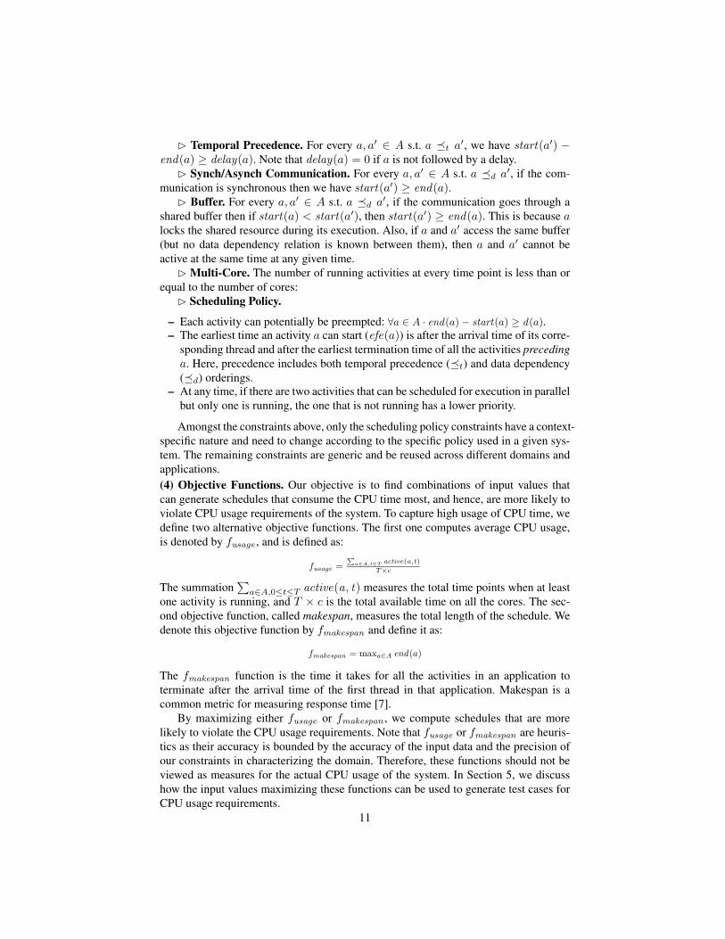
B Temporal Precedence. For every a, a′ ∈ A s.t. a �t a′, we have start(a′) −end(a) ≥ delay(a). Note that delay(a) = 0 if a is not followed by a delay.
B Synch/Asynch Communication. For every a, a′ ∈ A s.t. a �d a′, if the com-munication is synchronous then we have start(a′) ≥ end(a).
B Buffer. For every a, a′ ∈ A s.t. a �d a′, if the communication goes through ashared buffer then if start(a) < start(a′), then start(a′) ≥ end(a). This is because alocks the shared resource during its execution. Also, if a and a′ access the same buffer(but no data dependency relation is known between them), then a and a′ cannot beactive at the same time at any given time.
B Multi-Core. The number of running activities at every time point is less than orequal to the number of cores:
B Scheduling Policy.
– Each activity can potentially be preempted: ∀a ∈ A · end(a)− start(a) ≥ d(a).– The earliest time an activity a can start (efe(a)) is after the arrival time of its corre-
sponding thread and after the earliest termination time of all the activities precedinga. Here, precedence includes both temporal precedence (�t) and data dependency(�d) orderings.
– At any time, if there are two activities that can be scheduled for execution in parallelbut only one is running, the one that is not running has a lower priority.
Amongst the constraints above, only the scheduling policy constraints have a context-specific nature and need to change according to the specific policy used in a given sys-tem. The remaining constraints are generic and be reused across different domains andapplications.(4) Objective Functions. Our objective is to find combinations of input values thatcan generate schedules that consume the CPU time most, and hence, are more likely toviolate CPU usage requirements of the system. To capture high usage of CPU time, wedefine two alternative objective functions. The first one computes average CPU usage,is denoted by fusage , and is defined as:
fusage =P
a∈A,t∈T active(a,t)
T×c
The summation∑
a∈A,0≤t≤T active(a, t) measures the total time points when at leastone activity is running, and T × c is the total available time on all the cores. The sec-ond objective function, called makespan, measures the total length of the schedule. Wedenote this objective function by fmakespan and define it as:
fmakespan = maxa∈A end(a)
The fmakespan function is the time it takes for all the activities in an application toterminate after the arrival time of the first thread in that application. Makespan is acommon metric for measuring response time [7].
By maximizing either fusage or fmakespan , we compute schedules that are morelikely to violate the CPU usage requirements. Note that fusage or fmakespan are heuris-tics as their accuracy is bounded by the accuracy of the input data and the precision ofour constraints in characterizing the domain. Therefore, these functions should not beviewed as measures for the actual CPU usage of the system. In Section 5, we discusshow the input values maximizing these functions can be used to generate test cases forCPU usage requirements.
11

5 EvaluationThe main goal of our evaluation is to investigate whether our technique can effectivelyhelp engineers in deriving test cases for CPU usage requirements. The practical useful-ness of our approach depends on (1) whether the input to our approach can be providedwith reasonable overhead, and (2) whether the engineers can utilize the output of ouranalysis to derive test cases that can maximize CPU usage.
(i) Prerequisite and Overhead. As discussed before, the information required forCPU usage estimation is captured by the conceptual model in Figure 2. To gather thisinformation, we first built UML sequence diagrams for the IO drivers in our partnercompany using the existing design and implementation of the drivers. The resultingsequence diagrams were iteratively validated and refined in collaboration with the leadengineer of the IO drivers. Sequence diagrams are popular for visualizing concurrentmulti-threaded interactions and are intuitive to most developers as was confirmed in ourindustry collaboration [13].
The quantitative elements in Figure 2 for our case study were obtained as follows:The values for priority and period of the threads, and the size of the buffers were ex-tracted from the certification design documents and the IO driver code. The min/maxinter-arrival times of IODispatch, which is an aperiodic thread, and the values for themin/max duration of activities in our case study were extracted from the performanceprofiling logs of the drivers. We created the sequence diagrams augmented with the tim-ing information over 8 days, involving approximately 25 man-hours of effort. This wasconsidered worthwhile as such drivers have a long lifetime and are regularly certified.
Finally, we obtained the computing platform information in Figure 2 from the RTOSconfiguration and hardware design documents. Note that, given the mapping in Table 1,any modeling development environment that supports UML/MARTE can be used todevelop and manipulate our input design notation.
(ii) Test Case Derivation. The I/O drivers in our study are subject to certificationbased on the IEC61508 standard [14], which is one of the most detailed and widely-used functional safety standards. It specifies 4 levels of safety, called Safety IntegrityLevels (SILs). SIL1 is the lowest and SIL4 is the highest level. The drivers in our studyneed to be compliant to IEC61508 up to SIL2 or SIL3 depending on the context of theirapplication. Stress testing (subjecting the system to harsh inputs with the intention ofbreaking it [6]) is classified by IEC61508 as “Recommended” for SILs 1-2 and “HighlyRecommended” for SILs 3-4. “Highly Recommended” techniques/measures are oftenseen as “mandatory” by the certifiers, unless the supplier provides a convincing argu-ment as to why a highly recommended technique/measure does not apply. Subsequently,the engineers in our partner company needed to stress test the drivers (mandatory forSIL3 deployments).
We characterize the stress test cases in our case study by the delay times that (po-tentially) follow execution of activities, i.e., the delay attribute of the activity class inFigure 2. IO drivers are instantiated in different environments with different numbersand kinds of detectors and FMSs. The delay times after the IO driver activities must beset to values that match the load and speed of the detectors and FMSs.
Based on the engineers’ intuition, large and complex hardware configurations, e.g.,those consisting of several thousands of detectors, are more likely to violate the CPU
12

(Time) (Time)
Max: 50%Max: 50%
Max:550 ms
Max:550 ms
termination time termination timetermination time termination time
(% for cpu usage,ms for makespan)
(Val
ue)
(Val
ue)
(% for cpu usage,ms for makespan)
Fig. 5. The result of maximizing fmakespan and fusage (Section 4) for both parallel and non-parallel COMET implementations.
usage requirements. To identify the suspicious hardware configurations, however, theanalysis provided in this paper is necessary because the hardware configurations affectthe delay times of the IO drivers activities, and subsequently, the CPU usage estimates.
For example, the size of the delay time at step 3 of the data transfer scenario inFigure 1(b) can heavily impact the CPU usage. Specifically, the delay time cannot beso small that IODispatch (Figure 1(a)) keeps the CPU busy for so long that it exceedsthe given CPU usage requirement. Neither can the delay be too large, because thenpullData, which is periodic, may miss its deadline. Specifically it may quickly fill upthe Message Box 1 buffer, which in turn causes pullData to be blocked and waitingfor IODispatch to empty Message Box 1, which is now very slow due to a large delaytime. As a result, pullData may not be able to terminate before its next scan arrival.
To derive stress test cases based on the delay times of the activities, in our formula-tion in Figure 4, we specify delay as an output variable whose value is bounded withina range. The search then varies the values of these variables to maximize fmakespan andfusage . Those combinations that maximize our objective functions are more likely tostress the system to the extent that the CPU usage requirements are violated.
To perform the above experiment, we implemented the constraint optimization for-mulation in Figure 4 in COMET Version 2.1.0 [7]. We further used the native supportof COMET for parallel programming to create a distributed version of our COMET im-plementation that divides the search work-load among different cores. To perform theexperiment, we varied the observation time T from 1s to a few seconds and set thequantum time (i.e., the minimum time step that a scheduler may preempt activities) to10 ms. The input model included eight activities belonging to three parallel threads.
Figure 5 shows the result of our experiment, maximizing fmakespan and fusage forboth parallel and non-parallel COMET implementations. In both diagrams, the X-axisshows the time, and the Y-axis shows the size of fmakespan in ms, and the percentage forfusage . In our experiment, we used a complete (exhaustive) constraint solver of COMET,and ran it on a MacBook Pro with a 2.0 Ghz quad-core Intel Core i7 with 8GB RAM.As shown in the figure, the search terminated in both cases: after around 14 hours forthe non-parallel version, and after around 2 hours and 55 min for the parallel version.The maximum computed values are: 50% for fusage , and 550 ms for fmakespan . In thenon-parallel case, the maximum result was computed after around 1 hour and 10 minfor fmakespan , and 1 hour and 13 min for fusage . No higher value was found in theremainder of the search which took more than 14 hours in total. In the parallel case,
13

it took about 15 min to find the maximum for fusage , and 40 min to compute that forfmakespan . To make sure these values were indeed maximum, the search continued untilit terminated after 2 hours and 55 min.
In the end, we could compute maximum values for fmakespan and fusage in around2 hours and 55 min using COMET’s built-in support for parallel search. The values forthe delay times maximizing fmakespan and fusage are candidates for stress test cases.We have recorded these values and have communicated them to our partner company.
Currently, the engineers at our partner company spend several days simulating theirsystems and monitoring the CPU usage without following a systematic strategy forstressing the systems to their CPU usage limits. We expect that by executing their sys-tems based on the values produced by our approach, they can push the systems to stateswhere the CPU usage is maximized and ensure that the input delay times remain withinsafe margins. The engineers at our partner company intend to test their system usingour findings. Our experimental results and the input data values are available at [12].
6 Related WorkAll approaches to performance engineering and schedulability analysis require a modelof the time and concurrency aspects of the system under analysis [15]. Examples ofsuch modeling languages include queuing networks [16], stochastic Petri nets [17], andstochastic automata networks [18]. Recently, there has been a growing interest in devel-oping standardized languages to enhance the adoption of performance engineering con-cepts and techniques in the industry [19]. The most notable these languages is MARTEwhich extends UML with concepts for modeling and quantitative analysis of real-timeembedded systems [5]. While a UML-profile, MARTE also encompasses the timing andconcurrency abstractions in many other languages, e.g., Architecture Analysis and De-sign Language (AADL) [20]. As indicated by the mapping from our conceptual modelto MARTE (Section 3.2), the abstractions we use in our work already exist in MARTE.However, MARTE is a large profile and by itself does not provide guidelines on whatsubset of it is required for a particular type of analysis. Our conceptual model can thusbe viewed as a subset selection of MARTE, aimed specifically at CPU usage analysis.
The techniques for analysis of real-time systems can be divided into two generalgroups: (1) Approaches based on real-time scheduling theory [9]. These approachesestimate schedulability of a set of tasks through customized formulas and theorems thatoften assume worst case situations only such as worst case execution times, worst caseresponse times, etc. Their results, therefore, can be too conservative because due toinaccuracies in estimating worst-case time values, the worst-case situations may neverhappen in practice. As a result, in general, we cannot rely on schedulability theory alonewhen dealing with analysis of real-time systems. Moreover, extending these theories tomulti-core processors has shown to be a challenge [21, 22].
(2) Model-based approaches to schedulability analysis. The idea is to base theschedulability analysis on a system model that captures the details and specifics of real-time tasks. This provides the flexibility to incorporate specific domain assumptions anda range of possible scenarios, not just the worst cases [23, 24]. Most approaches that fallin this category, including our work, can deal with multi-core processors as well [24].
We formulate the problem of CPU usage analysis as a constraint optimization prob-lem. Our work is inspired by Job shop scheduling – a well-known optimization problem
14

where jobs are assigned to resources at particular times [25]. Job shop has several vari-ations. Our formulation is closest to the discrete resources variant [7], but differs fromit in that we need to specify scheduling policies used by the underlying RTOS.
Model checkers, in particular, real-time model checkers, e.g., UPPAAL [26], havebeen successfully used for the evaluation of time-related properties. Model checking isintended to be used for verification, i.e., to check if a given set of real-time tasks satisfysome property of interest. To adapt model checkers to checking different properties ofreal-time applications, the underlying state machines are built such that the question athand can be formulated as a reachability query. For example, in [24], in order to analyzeCPU-time usage, an idle state-machine is added to the set of interacting timed-automatato keep track of the CPU-time, and the error states were chosen so that their reachabilitycould lead to violation of the CPU-time usage limit.
In our work, the property to be checked is captured by a quantitative objectivefunction as opposed to a boolean reachability property, as in the case of model checking.Therefore, our work is more geared towards optimization with applications in test-casegeneration rather than verification. One significant practical advantage is that, to adaptour formulation to check other kinds of real-time properties, it often suffices to changethe objective function, and most of the constraints remain untouched. Lastly, to handlemultiple cores, the existing UPPAAL-based solution in [22] assumes that a mappingbetween threads and cores is given a priori. Our approach in contrast does not requireany mapping between threads and cores.
7 Conclusions and Future WorkWe provided a practical approach to support derivation of stress test cases for the CPUusage requirements of concurrent embedded applications running on multi-core plat-forms. We proposed a conceptual model that captures, independently from any mod-eling notation, the abstractions required for analysis of CPU usage. We mapped ourconceptual model onto the standard modeling language UML/MARTE to support theapplication of our approach in practice. We, then, formulated the CPU usage problemas a constraint optimization problem over our conceptual model, and implemented ourformulation in COMET. Our evaluation on a real case study shows that our approach(1) can be applied with practically acceptable overhead, and (2) can identify test casesthat maximize CPU usage. These (stress) test cases are crucial for building satisfactoryevidence to demonstrate that no safety risks are posed by potential CPU overloads. Fi-nally, we note that while our approach cannot provide proofs, we can always provideresults given a (partial) set of declarative constraints and within a time budget.
Our solution draws on a number of context factors (Section 2) which need to beascertained before our solution can be applied. While the generalizability of these fac-tors need to be further studied, we have found the factors to be commonplace in manyindustry sectors relying on embedded systems. In the future, we plan to perform largercase studies to better evaluate the generalizability and scalability of our approach andexperiment with other search methods, in particular, meta-heuristic search methods andhybrid approaches combining complete and meta-heuristic search strategies.Acknowledgments. We thank Bran Selic for his useful comments on an earlier draftof this paper. We thank the research council of Norway for partially funding this work.L. Briand was supported by a FNR PEARL grant.
15
References
1. Jackson, D., Thomas, M., Millett, L., eds.: Software for Dependable Systems: SufficientEvidence? National Academy Press (2007)
2. Henzinger, T., Sifakis, J.: The embedded systems design challenge. In: FM. (2006) 1–153. Lee, E., Seshia, S.: Introduction to Embedded Systems: A Cyber-Physical Systems Ap-
proach. http://leeseshia.org (2010)4. Clarke, E., Grumberg, O., Peled, D.: Model Checking. MIT Press (1999)5. A UML profile for MARTE: Modeling and analysis of real-time embedded systems (May
2009)6. Beizer, B.: Software testing techniques (2. ed.). Van Nostrand Reinhold (1990)7. Hentenryck, P.V., Michel, L.: Constraint-Based Local Search. The MIT Press (2005) www.
dynadec.com.8. Wind River VxWorks. http://www.windriver.com/products/vxworks/ (2009)9. Liu, J.W.S.: Real-time systems. Prentice Hall (2000)
10. Sprunt, B.: Aperiodic task scheduling for real-time systems. PhD thesis, Carnegie MellonUniversity, Pittsburgh, PA, USA (1990)
11. OMG: The Unified Modelling Language. Version 2.1.2. http://www.omg.org/spec/UML/2.1.2/ (2007)
12. Alesio, S.D.: The CPU usage constraints in COMET. http://home.simula.no/∼stefanod/
comet.pdf
13. Harel, D., Marelly, R.: Specifying and executing behavioral requirements: the play-in/play-out approach. Software and System Modeling 2(2) (2003) 82–107
14. IEC 61158: industrial communication networks - fieldbus specifications. International Elec-trotechnical Commission (2010)
15. Cortellessa, V., Marco, A.D., Inverardi, P.: Model-Based Software Performance Analysis.Springer (2011)
16. Lazowska, E., Zahorjan, J., Graham, S., Sevcik, K.: Quantitative system performance com-puter system analysis using queueing network models. In: Int. CMG Conference. (1984)786–788
17. Marsan, M., Balbo, G., Conte, G., Donatelli, S., Franceschinis, G.: Modelling with gener-alized stochastic petri nets. SIGMETRICS Performance Evaluation Review 26(2) (1998)2
18. Plateau, B., Atif, K.: Stochastic automata network for modeling parallel systems. IEEETrans. Software Eng. 17(10) (1991) 1093–1108
19. Petriu, D. In: Software Model-based Performance Analysis. John Wiley & Sons (2010)20. Hudak, J., Feiler, P.: Developing AADL models for control systems: A practitioner’s guide
(October 2006)21. Bertogna, M.: Real-Time Scheduling Analysis for Multiprocessor Platforms. PhD thesis,
Scuola Superiore Sant’Annna, Pisa (2007)22. David, A., Illum, J., Larsen, K., Skou, A. In: Model-Based Framework for Schedulability
Analysis Using UPPAAL 4.1. CRC Press (2010) 93–11923. Briand, L., Labiche, Y., Shousha, M.: Using genetic algorithms for early schedulability anal-
ysis and stress testing in real-time systems. Genetic Programming and Evolvable Machines7(2) (2006) 145–170
24. Mikucionis, M., Larsen, K., Nielsen, B., Illum, J., Skou, A., Palm, S., Pedersen, J., Hougaard,P.: Schedulability analysis using UPPAAL: Herscehl-Planck case study. In: Proceedings of4th International Symposiumo on Leveraging Applications of Formal Methods, Verificationand Validation; track: Quantitative Verification in Practice. (2010)
16

25. Applegate, D., Cook, W.: A computational study of the job-shop scheduling problem. IN-FORMS Journal on Computing 3(2) (1991) 149–156
26. Behrmann, G., David, A., Larsen, K.: A tutorial on uppaal. In Bernardo, M., Corradini, F.,eds.: International School on Formal Methods for the Design of Computer, Communication,and Software Systems, SFM-RT 2004. Revised Lectures. Volume 3185 of Lecture Notes inComputer Science., Springer Verlag (2004) 200–237
17