Experimental and analytical study of direct contact condensation of steam in water
Upload
khangminh22Category
view
2download
0
archivesof thermodynamics
Vol. 42(2021), No. 3, 45–62DOI: 10.24425/ather.2020.138109
Determining steam condensation pressurein a power plant condenser in off-designconditions
RAFAŁ LASKOWSKI∗ADAM SMYKADAM RUCIŃSKIJACEK SZYMCZYK
Institute of Heat Engineering, Faculty of Power and AeronauticalEngineering, Warsaw University of Technology,Nowowiejska 21/25, 00-665 Warsaw, Poland
Abstract The paper presents formulas which can be used to determinesteam condensation pressure in a power plant condenser in off-design con-ditions. The mathematical model provided in the paper makes it possibleto calculate the performance of the condenser in terms of condensing steampressure, cooling water temperature at the condenser outlet, and condensereffectiveness under variable load conditions as a function of three inputproperties: the temperature and the mass flow rate of cooling water at thecondenser inlet and the mass flow rate of steam. The mathematical modeltakes into account values of properties occurring in reference conditionsbut it contains no constant coefficients which would have to be establishedbased on data from technical specifications of a condenser or measurementdata. Since there are no such constant coefficients, the model of the steamcondenser proposed in the paper is universally applicable. The proposedequations were checked against warranty measurements made in the con-denser and measurement data gathered during the operation of a 200 MWsteam power unit. Based on the analysis, a conclusion may be drawn thatthe proposed means of determining pressure in a condenser in off-designconditions reflects the condenser performance with sufficient accuracy. Thismodel can be used in optimization and diagnostic analyses of the perfor-mance of a power generation unit.
∗Corresponding Author. Email: [email protected]

46 R. Laskowski, A. Smyk, A. Ruciński, and J. Szymczyk
Keywords: Thermal power plant; Steam condenser; Condenser model; Steam conden-sation pressure; Reference parameters; Steam condenser effectiveness
NomenclatureA – heat transfer area, m2
cF – coefficient of resistance of sedimentcM – coefficient of the type of tube materialcT – coefficient indicating the effect of cooling water temperature at
the condenser inletcw – water specific heat, J/(kg K)do – tube outer diameter, mmms – mass flow rate of steam, kg/smw – mass flow rate of cooling water, kg/sNTU – umber of transfer unitsp – pressure, kPaQ – flow rate of the heat transferred, Wr – latent heat, J/kgR – individual gas constant for steam, J(kg K)s′′, s′ – specific entropy of saturation for steam and water, J(kg K)t – temperature,◦CT – absolute temperature, KU – overall heat transfer coefficient, W/(m2 K)ww – average velocity of the water in the condenser tubes, m/sv′′, v′ – specific volume of saturation for steam and water, m3/kg
Greek symbols
ε – effectiveness of the steam condenser
Subscripts
i – inleto – outletr – reference parameterw – waters – steam2 – cooling water
1 Introduction
Mathematical models have been developed to analyze thermal systems andtheir components. Depending on particular processes, the models can berelated to steady or transient (dynamic) states. Mathematical models havebeen created mainly to determine the performance of thermal systems andtheir components. Mathematical modeling can be used at the design stage

Determining steam condensation pressure in a power plant condenser . . . 47
when a so-called design point, referring to a structure of the thermal sys-tem, is designed or to assess the performance of a system in off-designconditions. At the design stage, a structure of the system is created andcharacteristic properties of each component, such as geometry of the boiler,heat exchangers, and the turbine, are determined. For off-design condi-tions, the operation of a known structure of the system and geometry ofmachines and equipment is analyzed in conditions that are different fromdesign conditions. In this context the research focuses on how a change inoperating conditions, particularly the load, of generation sources affects theperformance of a power generation unit. For instance, in order to ensurean optimal operation of a unit, it is examined how properties of the cool-ing system [1–4] (temperature and the cooling water mass flow rate) affectthe performance of the condenser, the cooling system, and the whole ther-mal system of the unit, or how steam properties (pressure, temperature)influence the efficiency and power output of the system [5–8].
Mathematical modeling employs mainly three fundamental equations,namely the mass balance, energy balance, and moment of momentum bal-ance, which are used to work out pressure drops. As far is the turbine isconcerned, the energy balance is utilized to find the power output and ef-ficiency of the turbine, and in the case of heat exchangers to find the flowrate of the heat transferred and the effectiveness of the heat exchanger.For the turbine, the Fugel-Stodola equation can also be used as a relationbetween the ratio of outlet and inlet pressures to the rate of mass flowingthrough a group of stages. For the heat exchanger, we also have the Pé-clet equation [9, 10] which is used to determine the heat flow rate as theproduct of the overall heat transfer coefficient, heat transfer surface, andlogarithmic mean temperature difference between fluids.
When the performance of heat exchangers in off-design conditions isanalyzed, geometry of the heat exchanger (heat transfer surface area, lengthof the heat exchanger, and properties of the tube assembly) is given andtemperatures and mass flow rates of fluids at the heat exchanger inlet areknown. Temperatures of fluids at the heat exchanger outlet are to be found.We have two equations: the energy balance and the Péclet equation; thesecan be used to calculate temperatures of fluids at the heat exchanger outlet.Due to the implicit form of temperatures of fluids at the heat exchangeroutlet, the calculations have to be performed iteratively.
The greatest inaccuracy in heat exchanger modeling occurs when theoverall heat transfer coefficient is determined. The main reason for thisinaccuracy is that the overall heat transfer coefficient takes into account

48 R. Laskowski, A. Smyk, A. Ruciński, and J. Szymczyk
heat transfer coefficients that are calculated from approximate equationsestablished on the basis of a dimensional analysis. In addition, these equa-tions are non-linear and are functions of dimensionless numbers, such as theReynolds number and Prandtl number. In order to determine dimension-less values, one has to find out thermodynamic properties of fluids, suchas density, thermal conductivity, kinematic and dynamic viscosity, and spe-cific heat. The thermodynamic properties are most often established for theaverage temperature of fluids, taking into account temperatures at the heatexchanger inlet and outlet; this is why in order to find out temperatures offluids at the heat exchanger outlet, one has to make iterative calculations.
Depending on the complexity of the heat exchanger, its model may com-prise about ten to twenty equations, most frequently non-linear and implicitones, which have to be solved iteratively [11–13]. In addition, geometricaldata of a particular heat exchanger have to be provided, such as heat trans-fer surface area, length of the heat exchanger, pitch, tube diameter, shelldiameter, number of tubes, and material properties including thermal con-ductivity of a tube. It is not always possible, however, to provide exactgeometrical data. To reduce these difficulties in determining the perfor-mance of heat exchangers, approximate mathematical models have beendeveloped. The approximation may relate to the overall heat transfer coef-ficient [14], effectiveness of the heat exchanger [15–20], or temperatures offluids at the heat exchanger outlet [21–24].
The power plant condenser is most often a shell-and-tube heat exchanger.Steam flowing from the low-pressure part of the turbine condenses on theouter surface of tubes. Cooling water is flowing inside the tubes to removeheat of condensing steam and transfer it to the environment or a coolingtower. In the case of a steam condenser there are five variables: cooling watertemperature at the condenser inlet and outlet, the cooling water mass flowrate, steam pressure (temperature), and the steam mass flow rate. We havetwo equations, namely the energy balance and Péclet equation; therefore,by means of the condenser model we can determine two output properties.In most cases these properties are pressure (temperature) of condensingsteam and temperature of cooling water at the condenser outlet. The inputproperties of the condenser model include: the temperature and mass flowrate of cooling water, and the mass flow rate of steam. In addition to thesethree properties, the steam condenser performance is also influenced bythermal resistance of inert gases and fouling [25, 26]. Since there is a highlevel of vacuum in the condenser and the device is not leakproof, air issucked into it. The presence of air elevates pressure in the condenser and

Determining steam condensation pressure in a power plant condenser . . . 49
inhibits steam flow to the heat transfer surface, which results in deterio-ration of heat transfer conditions. Air is removed from the condenser bymeans of steam or water jet ejectors, and vacuum pumps have been used inrecent years for this purpose. Systems designed to remove inert gases usu-ally operate failure-free [27, 28]. As impurities contained in cooling waterprecipitate and build up on the inner surface of tubes, thermal resistanceof fouling becomes higher. Sponge balls are used to clean the inner surface(the heat transfer surface) of tubes to prevent sediment from building up onit [25]. The influence of inert gases and sediment on the surface of tubes wastaken into account in the model indirectly as the condenser performance inreference conditions.
The HEI (Heat Exchange Institute) model [29–31] is an example of anapproximate model designed to calculate the heat transfer coefficient fora condenser. In this model, the overall heat transfer coefficient is given asa product of a certain constant, the root of cooling water velocity, and co-efficients related to the effect of cooling water temperatures, tube material,tube outer diameter, and the deposit on the tube’s surface. The overallheat transfer coefficients are also approximated by means of a quadraticor linear function of temperature and the mass flow rate (velocity). Thedimensionless number of heat transfer units (NTU) [32], which is equal tothe product of the heat transfer coefficient and heat transfer surface areadivided by the lower heat capacity rate of both fluids, is also approximatedusing a dimensional analysis.
Approximate equations for the effectiveness of a heat exchanger have alsobeen developed. One of the first such equations is the one proposed by Beck-man in the form of products of temperatures at the heat exchanger inletand mass flow rates which are raised to the power of certain exponents [15].Other approximate equations for the condenser effectiveness can be foundin [17–20]. These equations also contain constant coefficients which have tobe determined using measurement data or manufacturer specifications ofa given heat exchanger. Black box models are most frequently used to de-velop approximate equations for fluid temperatures at the heat exchangeroutlet. These models are designed to examine how each input variable af-fects the output ones, and approximation is based on the resulting curves.
Approximate models often contain constant coefficients which need to becalculated from measurement data or technical specifications of a particu-lar heat exchanger. The coefficients in approximate equations take differentvalues for various types of heat exchangers, which causes some difficulty intheir application. This is why as far as approximate equations are con-

50 R. Laskowski, A. Smyk, A. Ruciński, and J. Szymczyk
cerned, attempts have been made to include reference parameters (whichare most commonly parameters relevant to the nominal state) and to reducethe number of constant coefficients with little compromise on accuracy ofthe model.
The application of reference parameters in an approximate equation forthe performance of a condenser is shown in [33]. The proposed equation isless accurate for small cooling water mass flow rates.
In [34], in order to determine cooling water temperature at the con-denser outlet and steam temperature (pressure), two equations are given inthe form of functions of only inlet variables, that is temperature and massflow rate of cooling water at the condenser inlet, the steam mass flow rate,and values of these properties in reference conditions. These two proposedequations contain no constant coefficients, which makes them universal atthe expense of a relatively small error of the model. Reference parameterswere taken for the average cooling water temperature at the condenser inlet.Cooling water temperature at the condenser outlet was calculated from thefirst equation. This equation was formulated from the energy balance con-sidering the reference parameters and assuming that the ratio of actual heatof condensing steam to that in reference conditions is approximately equalto one. The second approximate equation for the terminal temperature dif-ference that makes it possible to calculate steam temperature (pressure)was proposed based on curves which were generated by a condenser sim-ulator for a wide range of changes of input properties. The approximateequation for the terminal temperature difference as a function of the steammass flow rate containing reference properties was proposed based on theanalysis of the condenser characteristics. Since the reference parameters aretaken for the average cooling water temperature and it is assumed that theterminal temperature difference depends only on the steam mass flow rate(which has the greatest impact), the inaccuracy of the model increases forcooling water temperatures that are considerably different from the refer-ence value.
The aim of this paper is to present a highly accurate approximate equa-tion for the condensing steam pressure as a function of the cooling watermass flow rate and temperature at the condenser inlet, containing referenceparameters and no constant coefficients which would have to be obtainedfrom technical documentation or measurement data of a particular heatexchanger. Since there are no such constant coefficients, the proposed equa-tion can be applied universally. The paper presents an approximate modelof a condenser that can be used to calculate the condensing steam pres-

Determining steam condensation pressure in a power plant condenser . . . 51
sure (temperature) being the key property influencing the performance ofa power plant condenser. In addition, an equation for cooling water temper-ature at the condenser outlet is given. The proposed equations were checkedagainst guarantee measurements made in the condenser and measurementdata gathered during the operation of a 200 MW steam power unit. Theproposed model takes into account the initial thermal resistance of foulingand inert gases by means of reference parameters.
2 Mathematical model of a steam condenser
2.1 Equation for cooling water temperatureat the condenser outlet
Using the energy balance of the condenser based on data of the current op-erating point and reference data (as reference parameters, it usually takesnominal parameters), we obtain the cooling water temperature at the con-denser outlet that can be given as
t2o = t2i + ms
msr
mwr
mw(t2or − t2ir) . (1)
In off-design conditions, both the steam enthalpy at the outlet of the lowpressure part of the turbine (at the condenser inlet) and the steam drynessfraction change. Changes in these properties are rather small [8], which al-lows us to conclude that the ratio of heat of condensing steam at the currentoperating point to the one in reference conditions is approximately equal toone. This assumption was verified as correct in [34]. In order to determinecooling water temperature at the condenser outlet, one needs values of cool-ing water temperature (t2i) and mass flow rate (mw) at the condenser inlet,the steam mass flow rate (ms), and values of these properties in referenceconditions.
2.2 Equation for the steam condenser effectiveness
The condenser effectiveness is calculated from the energy balance and thePéclet equation:
Q = mwcw (t2o − t2i) , (2)
Q = UA∆Tln , (3)

52 R. Laskowski, A. Smyk, A. Ruciński, and J. Szymczyk
where the logarithmic mean temperature difference of a condenser takesthe form
∆T ln = t2o − t2i
ln ts − t2its − t2o
. (4)
On rearranging Eqs. (2) to (4), the effectiveness of the condenser can begiven as
ε = t2o − t2its − t2i
= 1− e−NTU, (5)
where NTU isNTU = UA
mwcw. (6)
The overall heat transfer coefficient according to the HEI standard [29–32]has the form
U = 6.47878(441.325− do)√
wwcT cMcF , (7)
where: cT – coefficient indicating the effect of cooling water temperatureat the condenser inlet, cM – coefficient of the type of tube material, cF –coefficient of the resistance of sediment.
Assuming C1 to be constant and equal to
C1 = 6.47878(441.325− do)cMcF (8)
the equation for the overall heat transfer coefficient can be given as
U = C1√
ww cT , (9)
where cT according to the HEI standard has the form
cT = 1.395− e−t2i
22.61 − t2i − 21166 . (10)
The dependence of cT as a function of cooling water temperature accord-ing to Eq. (10) and its power function approximation are shown in Fig. 1.It is proposed to approximate cT by means of a power function accordingto the formula
cT = C2 (t2i)0.22 . (11)

Determining steam condensation pressure in a power plant condenser . . . 53
Figure 1: The dependence of cT as a function of cooling water temperature according toEq. (10) and its power function approximation.
Taking into account the equation of continuity for the cooling water massflow rate, the ratio of the overall heat transfer coefficient to its value inreference conditions can be given as
U
Ur=√
ww√wwr
cTcTr
=√
mw√mwr
(t2it2ir
)0.22. (12)
Taking into account Eqs. (5) and (6), the overall heat transfer coefficientin reference conditions can be also written in the form
Ur = −mwrcwA
ln(1− εr). (13)
On considering Eqs. (12) and (13), the number of transfer units can beexpressed as
NTU = − ln(1− εr)√
mwr
mw
(t2it2ir
)0.22. (14)
Thus, the effectiveness of the condenser can be given as
ε = 1− exp[ln(1− εr)
√mwr
mw
(t2it2ir
)0.22]
. (15)
The condenser effectiveness is thus given as a function of temperature andthe mass flow rate of cooling water at the condenser inlet and their valuesin reference conditions.

54 R. Laskowski, A. Smyk, A. Ruciński, and J. Szymczyk
2.3 Equation for condensing steam pressure
Once the condenser effectiveness is calculated from Eq. (15), steam con-densation temperature can be determined from Eq. (5) in the form
ts = t2i + (t2o − t2i)ε
= t2i + (t2o − t2i)
1− exp[ln(1− εr)
√mwr
mw
(t2it2ir
)0.22] . (16)
In saturation conditions pressure of condensing steam is a function of itstemperature, ps = f(ts). Pressure of condensing steam as a function oftemperature can be calculated using approximate equations available ina number of software applications, such as the IF97 formulation in MS Excelworksheet XSteam_Excel_v2.6.xls [35], or from the Clapeyron–Clausiusequation (
v′′ − v′)
dps =(s′′ − s′
)dT s . (17)
At phase transition the difference between specific entropy of saturatedsteam and that of saturated water is expressed as
s′′ − s′ = r
Ts. (18)
Assuming that the specific volume of saturated steam greatly exceeds thatof saturated water (v′′ � v′) and that for the saturated steam we can use theClapeyron ideal gas equation (v′′ = RTs/ps), Eq. (17) can be transformedinto
dpsps
= r
R
dTsTs
. (19)
On integrating Eq. (19) between the current and reference parameters andassuming a constant value of phase transition heat, we obtain
ps = psrerrR
[1
Tsr− 1
Ts
]. (20)
Figure 2 compares pressure calculated from Eq. (20) and according to theapproximation formulation IF97 implemented in XSteam_Excel_v2.6.xlsas a function of saturation temperature. The difference (the relative error)is 2% or less. The reference parameters were taken for the reference steampressure (psr) of 4 kPa, which corresponds to the reference steam temper-ature (tsr) of 28.96◦C or (Tsr) of 302.11 K. The smallest relative error is atthe point of reference conditions and is increasing up to a maximum of 2%when steam properties are farther from this point.

Determining steam condensation pressure in a power plant condenser . . . 55
Figure 2: Saturation pressure as a function of saturation temperature according toEq. (20) and XSteam_Excel_v2.6.xls.
For prescribed values of the steam mass flow rate at the condenser inlet(ms), the cooling water mass flow rate (mw), and cooling water temper-ature at the condenser inlet (t2i), Eqs. (1), (15), (16), and (20) are usedto calculate cooling water temperature at the condenser outlet (t2o), thecondenser effectiveness (ε), steam condensation temperature (ts), and con-densing steam pressure (ps).
3 Results
The proposed equations were first checked against measurement data col-lected from a 200 MW power generation unit under variable load condi-tions. Table 1 lists data available from five measurements. The followingmeasurements were taken in the condenser: cooling water temperature atthe condenser inlet and outlet, cooling water mass flow rate, power outputof the unit, steam mass flow rate, and pressure of steam condensing in thecondenser. Table 1 also lists values of condensing steam temperature andthe condenser effectiveness according to measurement data.
Properties (condensing steam pressure and cooling water temperatureat the condenser outlet) calculated from the proposed equations includingrelative errors are listed in Table 2.
Figure 3 compares cooling water temperatures at the condenser outletaccording to measurements and calculated from the proposed Eq. (1) invariable load conditions of the power unit.

56 R. Laskowski, A. Smyk, A. Ruciński, and J. Szymczyk
Table 1: Properties measured in the condenser.
Property Parameter UnitMeasurement
1 2 3 4 5
Power output of the unit P MW 140 160 180 200 225Steam mass flow rate at thecondenser ms kg/s 82.042 90.46 101.188 112.64 127.37
Cooling water mass flow rate mw kg/s 8048.8 8243.9 8123.2 8073 8104.1Mean water temp. at the con-denser inlet t2i
◦C 7.91 10.14 8.665 8.82 10.555
Mean water temp. at the con-denser outlet t2o
◦C 13.54 16.17 15.48 16.42 19.04
Pressure of steam in the con-denser ps kPa 2.1 2.4 2.5 2.7 3.2
Temperature of steam in thecondenser ts ◦C 18.27 20.41 21.08 22.34 25.16
Condenser effectiveness ε – 0.543 0.587 0.549 0.562 0.581
Table 2: Properties calculated from the proposed equations including relative errors.
Property Parameter UnitMeasurement
1 2 3 4 5
Power output of the unit P MW 140 160 180 200 225Pressure of steam in the con-denser, measured ps kPa 2.10 2.40 2.50 2.70 3.20
Pressure of steam in the con-denser, calculated ps c kPa 2.04 2.43 2.43 2.65 3.20
Mean water temp. at the con-denser outlet, measured t2o
◦C 13.54 16.17 15.48 16.42 19.04
Water temp. at the condenseroutlet, calculated t2o_c
◦C 13.41 16.06 15.39 16.35 19.04
Relative error of steam pres-sure δps % 2.76 –1.33 2.97 1.79 0.00
Relative error of cooling wa-ter temp. at the condenseroutlet
δt2o % 0.94 0.66 0.58 0.41 0.00
Condenser effectiveness cal-culated from the equations εc – 0.555 0.565 0.564 0.570 0.581
Temperature of steam in thecondenser calculated from theequation
ts_c◦C 17.82 20.63 20.59 22.04 25.16
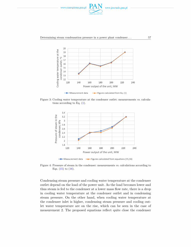
Figure 4 compares pressures of steam in the condenser according to mea-surements and calculated from Eqs. (15) to (17) in variable load conditionsof the power unit.
Determining steam condensation pressure in a power plant condenser . . . 57
Figure 3: Cooling water temperature at the condenser outlet: measurements vs. calcula-tions according to Eq. (1).
Figure 4: Pressure of steam in the condenser: measurements vs. calculations according toEqs. (15) to (16).
Condensing steam pressure and cooling water temperature at the condenseroutlet depend on the load of the power unit. As the load becomes lower andthus steam is fed to the condenser at a lower mass flow rate, there is a dropin cooling water temperature at the condenser outlet and in condensingsteam pressure. On the other hand, when cooling water temperature atthe condenser inlet is higher, condensing steam pressure and cooling out-let water temperature are on the rise, which can be seen in the case ofmeasurement 2. The proposed equations reflect quite close the condenser

58 R. Laskowski, A. Smyk, A. Ruciński, and J. Szymczyk
performance: in both cases the curves nearly coincide. Major discrepanciesoccur for steam pressure, but this stems from the fact that the measurementof condensing steam pressure is prone to greater errors than the measure-ment of cooling water temperature at the condenser outlet due to a largevolume of space where steam is condensing.
The proposed equations were also checked against operational data ofa 200 MW power generation unit. The authors had hourly measurementsspanning one year of the power plant operation. During a year the unitoperated for about 7000 hours; during the rest of the year the unit was shutdown and maintenance activities were carried out. Based on measurementdata, cooling water temperature at the condenser outlet was calculatedfrom Eq. (1). The difference between measured cooling water temperaturesat the condenser outlet and those calculated from the equation is shown inFig. 5.
Figure 5: The difference between cooling water temperatures at the condenser outlet:measured vs. calculated using Eq. (1).
The difference between measured condensing steam temperatures and thosecalculated using Eqs. (15) and (16) is shown in Fig. 6.
The difference between measured cooling water temperatures at the con-denser outlet and those calculated from the equations is in the range of±1.0◦C. This is also the case with the difference between condensing steamtemperatures measured and calculated from Eqs. (15) and (16). For somedata this range is slightly exceeded. Temperature is measured in powerplants to an accuracy of ±1.0◦C.

Determining steam condensation pressure in a power plant condenser . . . 59
Figure 6: The difference between steam temperatures: measured vs. calculated fromEqs. (15) and (16).
4 Conclusions
The paper proposes a formula to calculate steam condensation pressure(temperature) in a power plant condenser in off-design conditions. Theinput properties of the model are: the mass flow rate of steam and thetemperature and mass flow rate of cooling water at the condenser inlet. Inorder to determine the performance of the condenser in terms of condensingsteam pressure and cooling water temperature at the condenser outlet inoff-design conditions, one has to provide the input properties and their cor-responding values in reference conditions. Ideally, the reference propertiesshould be taken as nominal operating parameters of the power unit.
The proposed equations contain no constant coefficients which wouldhave to be established based on data from technical specifications of a con-denser or measurement data. Since there are no such constant coefficients,the proposed equations describing the condenser performance in off-designconditions are universally applicable.
The proposed equations were checked against guarantee measurementsand measurement data during the operation of a 200 MW steam powerunit. As the analysis indicates, the proposed equations proved to be highlyaccurate. The proposed model can be used in the event of off-design oper-ating conditions of a condenser and for diagnostic purposes to assess thetechnical condition of a condenser.
In addition to these three key inlet properties (the mass flow rate ofsteam and the temperature and mass flow rate of cooling water at the

60 R. Laskowski, A. Smyk, A. Ruciński, and J. Szymczyk
condenser inlet), the condenser performance is also influenced by thermalresistance of inert gases (air) and fouling, and the steam dryness fraction.In off-design conditions, the steam dryness fraction at the condenser inletchanges only little. For instance, for the condenser under consideration thesteam dryness fraction varied between 0.92 and 0.94, which makes the ratioof heat of condensing steam at the current operating point to the one inreference conditions approximately equal to one. This condition was usedto devise Eq. (1). The proposed model takes into account the initial (ref-erence) thermal resistance of inert gases and fouling. If vacuum conditionsin the condenser deteriorate or the fouling thermal resistance increases, thecondenser performance will drop since steam in the condenser will condenseat a higher pressure. The proposed mathematical model can be thereforeused not only to analyze the operation of a power unit in off-design condi-tions but also as a diagnostic tool to show a difference between the pressurereading and the pressure calculated from the proposed condenser model. Noincrease in fouling thermal resistance was observed in the condenser con-sidered in the paper since the condenser was constantly cleaned by meansof sponge balls on the cooling-water side. The inert gas removal system alsooperated as intended for measurement data included in the analysis.
The paper proposes a relatively simple model of a condenser in off-designconditions. By combining heat flow equations, measurement data and pa-rameters in reference conditions, the model proved to be satisfactorily ac-curate. This model can be used in optimization and diagnostic analyses ofthe performance of a power generation unit.
Received 3 April 2021
References[1] Salij A., Stepień J.C.: Performance of Turbine Condensers in Power Units of
Thermal Systems. Kaprint, Warsaw 2013 (in Polish).
[2] Rusowicz A.: Issues Concerning Mathematical Modelling of Power Condensers.Warsaw University of Technology, Warsaw 2013 (in Polish).
[3] Grzebielec A., Rusowicz A.: Thermal resistance of steam condensation in hori-zontal tube bundles. J. Power Technol. 91(2011), 1, 41–48.
[4] Laskowski R., Smyk A., Rusowicz A., Grzebielec A.: Selection of cooling watermass flow rate at variable load for 200 MW power unit. Rynek Energii (2020), 3,41–46 (in Polish).

Determining steam condensation pressure in a power plant condenser . . . 61
[5] Durmayaz A., Sogut O. S.: In?uence of cooling water temperature on the e?ciencyof a pressurized-water reactor nuclear-power plant. Int. J. Energ. Res. 30(2006), 10,799–810.
[6] Atria S.I.: The influence of condenser cooling water temperature on the thermalefficiency of a nuclear power plant. Ann. Nucl. Energy 80(2015), 371–378.
[7] Laković M.S., et.al. Stojiljković M.M. , Laković S.V., Stefanović V.P.,Mitrović D.D.: Impact of the cold end operating conditions on energy efficiency ofthe steam power plants. Therm. Sci. 14(2010), Suppl., S53–S66.
[8] Laskowski R., Smyk A., Lewandowski J., Rusowicz A.: Cooperation of a steamcondenser with a low-pressure part of a steam turbine in off-design conditions. Am.J. Energ. Res. 3(2015), 1, 13–18.
[9] Cengel Y.A.: Heat Transfer. McGraw-Hill, 1998.[10] Holman J.P.: Heat Transfer. McGraw-Hill, New York 2002.[11] Weber G.E., Worek W.M.: Development of a method to evaluate the design per-
formance of a feedwater heater with a short drain cooler. J. Eng. Gas Turbines Power116(1994), 2, 434–441.
[12] Weber G.E., Worek W.M.: The application of a method to evaluate the designperformance of a feedwater heater with a short drain cooler. J. Eng. Gas TurbinesPower 117(1995), 2, 384–387.
[13] Szkłowier G.G., Milman O.O.: Research and Calculations of Condensing Systemsof Steam Turbines. Energoatomizdat, Moskwa 1985 (in Russian).
[14] Pattanayak L., Padhi B.N., Kodamasingh B.: Thermal performance assessmentof steam surface condenser. Case Stud. Therm. Eng. 14(2019), 100484.
[15] Beckman G., Heil G.: Mathematische Modelle für die Beurteilung von Kraftwerk-sprozessen. EKM Mitteillungen (1965), 10.
[16] Laskowski R., Lewandowski J.: Simplified and approximated relations of heattransfer effectiveness for a steam condenser. J. Power Technol. 92(2012), 4, 258–265.
[17] Laskowski R.M.: A mathematical model of the steam condenser in the changedconditions. J. Power Technol. 92(2012), 2, 101–108.
[18] Szapajko G., Rusinowski H.: Empirical modelling of heat exchangers in a CHPplant with bleed-condensing turbine. Arch. Thermodyn. 29(2008), 4, 177–184.
[19] Szapajko G., Rusinowski H.: Mathematical modelling of steam–water cycle withauxiliary empirical functions application. Arch. Thermodyn. 31(2010), 2, 165–183.
[20] Bahadori A.: Simple method for estimation of effectiveness in one tube pass andone shell pass counter-flow heat exchangers. Appl. Energ. 88(2011), 11, 4191–4196.
[21] Vera-García F., García-Cascales J.R., Gonzálvez-Maciá J., Cabello R.,Llopis R., Sanchez D., Torrella E.: A simplified model for shell-and-tubes heatexchangers: practical application. Appl. Therm. Eng. 30(2010), 10, 1231–1241.
[22] Patrascioiu C., Radulescu S.: Modeling and simulation of the double tube heatexchanger. Case studies. Advances in Fluid Mechanics & Heat & Mass Transfer(P. Mastny, V. Perminov, Eds.). In: Proc. 10th WSEAS Int. Conf. on Heat Transfer,

62 R. Laskowski, A. Smyk, A. Ruciński, and J. Szymczyk
Thermal Engineering and Environment (HTE ’12) and Proc. 10th WSEAS Int.Conf. on Fluid Mechanics & Aerodynamics (FMA ’12), Istanbul, Aug. 21–23, 2012,WSEAS, 2012, 35–41.
[23] Patrascioiu C., Radulescu S.: Prediction of the outlet temperatures in tripleconcentric-tube heat exchangers in laminar flow regime: case study. Heat Mass Trans-fer 51(2015), 59–66.
[24] Laskowski R.: The black box model of a double-tube counter-flow heat exchanger.Heat Mass Transfer (2014), 10.1007/s00231-014-1482-2:1–9.
[25] Chmielniak T., Trela M., Eds.: Diagnostics of New-Generation Thermal PowerPlants. Wyd. IMP PAN, Gdańsk 2008.
[26] Butrymowicz D., Trela M.: Influence of fouling and inert gases on the perfor-mance of regenerative feedwater heaters. Arch. Thermodyn. 23(2002), 1-2, 127–140.
[27] Badur J., Kowalczyk T., Ziółkowski P., Tokarczyk P., Woźniak M.: Studyof the effectiveness of the turbine condenser air extraction system using hydro ejec-tors. Trans. Inst. Fluid-Flow Mach. 131(2016), 41–53.
[28] Tokarczyk P., Woźnizk M., Badur J., Kowalczyk T., Ziółkowski P.: Issue ofthe temperature of water supplied to hydro ejector and its influence on performanceof steam turbine condenser. Energetyka 70(2017), 10 (in Polish).
[29] HEI Standards for Steam Surface Condensers (11th Edn.). Heat Exchange Institute,Cleveland 2012.
[30] Prieto M.M., Suárez I.M., Montanés E.: Analysis of the thermal performanceof a church window steam condenser for different operational conditions using threemodels. Appl. Therm. Eng. 23(2003), 2, 163–178.
[31] Wróblewski W., Dykas S., Rulik S.: Selection of the cooling system configurationfor an ultra-critical coal-fired power plant. Energ. Convers. Manage. 76(2013), 554–560.
[32] Jian-qun Xu, Tao Yang, You-yuan Sun, Ke-yi Zhou, Yong-feng Shi: Researchon varying condition characteristic of feedwater heater considering liquid level. Appl.Therm. Eng., 67 (2014), 179–189.
[33] Laskowski R.: Relations for steam power plant condenser performance in off-designconditions in the function of inlet parameters and those relevant in reference condi-tions. Appl. Therm. Eng. 104(2016), 528–536.
[34] Laskowski R., Smyk A., Rusowicz A., Grzebielec A.: A useful formulas todescribe the performance of a steam condenser in off-design conditions. Energy204(2020) 117910.
[35] Wagner W., Kretzschmar H.J.: International Steam Tables – Properties of Wa-ter and Steam based on the Industrial Formulation IAPWS-IF97. Springer, 2008.
Copyright © 2022 FDOKUMEN