Experimental and analytical study of direct contact condensation of steam in water
11
Nuclear Engineeri.ng and Design ELSEVIER Nuclear Engineering and Design 147 (1994) 425-435 Experimental and analytical study of direct contact condensation of steam in water Kuo-Shing Liang a, Peter-Griffith b " Institute of Nuclear Energy Research, P.O. Box 3-3 Lung-Tang, Taiwan, ROC b Department of Mechanical Engineering, Massachusetts Institute of Technology, Cambridge, MA 02139, USA (Received 15 August 1991) Abstract The object of this work is to improve our understanding and analysis capability for direct contact condensation of steam in water. Transition criteria between regimes of direct contact condensation have been proposed. A transition criterion for the onset of chugging has been developed from the transient conduction model as well as a criterion for the existence of a condensing jet from the two-layer turbulent eddy transfer model In order to analyze the effect of non-condensable gas on the chugging boundary, a transient conduction-diffusion model for steam and steam-gas mixtures can be calculated. In particular, the amount of non-condensable gas required to suppress chugging can be quantified by use of this model. The critical gas content is found to be of the order of a few percent. In addition, a methodology is suggested for calculating the product of the interfacial area and the heat transfer coefficient for oscillatory jets. All the models and transition criteria developed are applicable for upward steam injection only with the exception of the methodology used for calculating the heat transfer of high velocity steam jets. 1. Introduction In a water-cooled reactor, no matter what kind of design it is, it is almost inevitable that direct contact condensation will be encountered some- where during transient or accident conditions. Generally speaking, there are three configura- tions in which this condensation occurs: blowing steam into a water-filled region, injecting water into a steam-filled region and condensing steam on a stratified flow of water. No matter what configuration is present, the process controlling direct contact condensation is always how rapidly the fresh, cold water can be brought to the con- densing interface. Owing to the variety of ways that the liquid can be brought into contact with 0029-5493/94/$07.00 © 1994 Elsevier Science B.V. All rights SSDI 0029-5493(93)E0257-K the steam, the associated interfacial heat transfer coefficient can exhibit variation of as much as three orders of magnitude [1]. If the water around the interface is turbulent enough, the interfacial heat transfer coefficient can be as large as 10 3 kW/m 2" K. Several reactor safety analysis computer codes have been successfully developed, and widely used throughout the world to assess reactor safety. These codes include RELAP5[2] and TRAC[3]. Unfortunately, the models used in TRAC or RE- LAP5 do not necessarily reflect the reality of the process of direct contact condensation. For in- stance, since the flow regime maps used in those codes are based on data taken in adiabatic flows of gases and liquids, none of these maps can be reserved
-
Upload
independent -
Category
Documents
-
view
4 -
download
0
Transcript of Experimental and analytical study of direct contact condensation of steam in water
Nuclear Engineeri.ng and Design
ELSEVIER Nuclear Engineering and Design 147 (1994) 425-435
Experimental and analytical study of direct contact condensation of steam in water
K u o - S h i n g L i a n g a, P e t e r - G r i f f i t h b
" Institute of Nuclear Energy Research, P.O. Box 3-3 Lung-Tang, Taiwan, ROC b Department of Mechanical Engineering, Massachusetts Institute of Technology, Cambridge, MA 02139, USA
(Received 15 August 1991)
Abstract
The object of this work is to improve our understanding and analysis capability for direct contact condensation of steam in water. Transition criteria between regimes of direct contact condensation have been proposed. A transition criterion for the onset of chugging has been developed from the transient conduction model as well as a criterion for the existence of a condensing jet from the two-layer turbulent eddy transfer model In order to analyze the effect of non-condensable gas on the chugging boundary, a transient conduction-diffusion model for steam and steam-gas mixtures can be calculated. In particular, the amount of non-condensable gas required to suppress chugging can be quantified by use of this model. The critical gas content is found to be of the order of a few percent. In addition, a methodology is suggested for calculating the product of the interfacial area and the heat transfer coefficient for oscillatory jets. All the models and transition criteria developed are applicable for upward steam injection only with the exception of the methodology used for calculating the heat transfer of high velocity steam jets.
1. Introduct ion
In a water-cooled reactor, no matter what kind of design it is, it is almost inevitable that direct contact condensation will be encountered some- where during transient or accident conditions. Generally speaking, there are three configura- tions in which this condensation occurs: blowing steam into a water-filled region, injecting water into a steam-filled region and condensing steam on a stratified flow of water. No matter what configuration is present, the process controlling direct contact condensation is always how rapidly the fresh, cold water can be brought to the con- densing interface. Owing to the variety of ways that the liquid can be brought into contact with
0029-5493/94/$07.00 © 1994 Elsevier Science B.V. All rights SSDI 0029-5493(93)E0257-K
the steam, the associated interfacial heat transfer coefficient can exhibit variation of as much as three orders of magnitude [1]. If the water around the interface is turbulent enough, the interfacial heat transfer coefficient can be as large as 10 3 k W / m 2" K.
Several reactor safety analysis computer codes have been successfully developed, and widely used throughout the world to assess reactor safety. These codes include RELAP5[2] and TRAC[3]. Unfortunately, the models used in TRAC or RE- LAP5 do not necessarily reflect the reality of the process of direct contact condensation. For in- stance, since the flow regime maps used in those codes are based on data taken in adiabatic flows of gases and liquids, none of these maps can be
reserved
426 I~-S. Liang, P. Griffith / Nuclear Engineering and Design 147 (1994) 425-435
applied directly to the process of direct contact condensation without introducing extra uncer- tainties.
Improving our understanding and analysis ca- pability for direct contact condensation of steam in water is the primary objective of this paper. Regimes associated with direct contact condensa- tion of steam in water have been investigated and transition criteria between the important regimes have been proposed. We would particularly like to know when chugging will occur, since it will generally introduce major pressure fluctuations to the system. With the models developed in this work, engineers can easily identify the regime in which he is operating, and select an appropriate method of avoiding chugging. The transient con- duction-diffusion model developed can quantify how much non-condensable gas is required to eliminate chugging or the pipe size can be al- tered. Finally, a methodology suitable for inser- tion into a code is suggested for calculating the interfacial area and heat transfer coefficient for direct contact condensation [4]. In the proposed method, a unique function is analytically defined which is named the integral condensation distribu- tion function. With this function, the interfacial quantities required for analytical use can be sys- tematically generated, particularly for the oscilla- tory jetting regime. While only those whose work was used specifically in this paper are cited here,
an extensive bibliography with 75 references is included in ref. [4].
2. Experiments
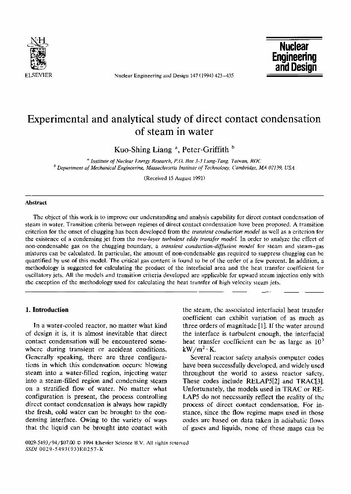
To investigate the direct contact condensation of steam in water, a t ransparent test section was designed. A controlled amount of steam was in- jected directly into the test section and then mixed with water inside. Fresh water was contin- ually pumped into the test section so that we could set the test conditions as required. Water discharged from the test section was dumped directly to a drain. In this design, both the steam flow and the water flow could be manually ad- justed. In addition, the water temperature and air content could also be adjusted by mixing a con- trolled amount of air directly into the steam branch before mixing the steam with the water. A schematic diagram of our system is shown in Fig. 1. The test section had a rectangular cross sec- tion. Two sides of it were transparent. The height of the test section is about 127 cm. The cross section is 5.00 cm by 3.81 cm. The equivalent diameter of the steam injector is 1.9 cm. The windows were placed in the middle of the test section so we could observe the mixing patterns inside. Both steam and water were brought in at the bot tom of the test section, but from opposite
. . . . . . . . ~ n l l Tank
i~te Utute | I
D r a i n a m ~
Pump
Drmn
Fig. 1. Schematic diagram of the experimental facility.
~ ImUtute Steam
Drain
K.-S. Liang, P. Griffith / Nuclear Engineering and Design 147 (1994) 425-435 427
sides. A partition plate was inserted at the lower part of the test section, so that the coming steam and water were separated and directed upwards until the end of the partition plate. Above the partition plate, steam and cold water came into direct contact. The window started right above the partition plate so that the mixing patterns could be clearly observed; the window was long enough so that all the condensation took place within view. The length of the condensing steam jet or elevation to which the bubbles persisted was the primary measurement made in this appa- ratus.
All the experiments were performed slightly above atmospheric pressure with water tempera- tures ranging from 60 to 90°C. The inlet Mach numbers for the steam ranged up to 0.4. The maximum water flow rate was about 60 kg/s . These parameters cover the ranges that are of interest in nuclear reactor safety systems.
3. Regime transitions without air being present
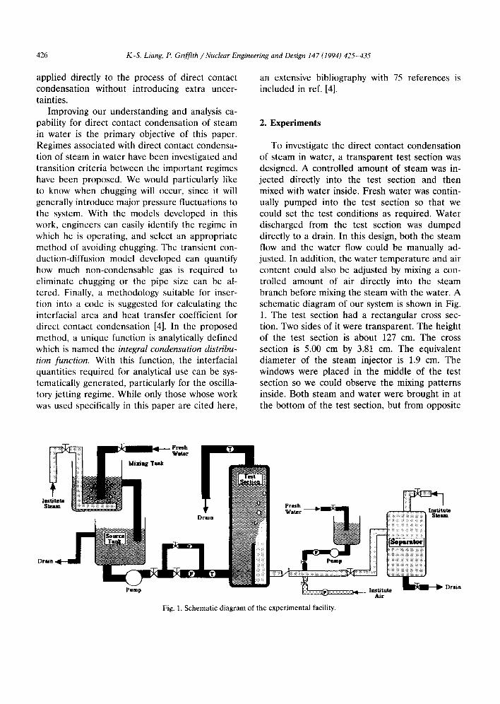
Generally speaking, when steam is blown into a pool of subcooled water, the following five regimes can be classified [5]: (1) chugging, (2) low frequency bubbling with detached bubbles, (3) high frequency bubbling with attached bubbles, (4) oscillatory steam jets, and (5) stable steam jets, as shown in Fig. 2. In our experiments, all these regimes were observed except for stable steam jets, which require a choked steam velocity at the injection nozzles in order to isolate the steam flow from the pool pressure.
Considering the transition between chugging and bubbling, it can easily be imagined that, if the condensation rate is larger than the steam supply rate, the interface will be drawn back into the vent pipe. Once the interface retreats into the injector, chugging is initiated. When chugging occurs, large pressure pulses are produced from time to time. In our research, the phenomenon of chugging was not the primary concern, rather we wished to provide a simple method of eliminating chugging. This was accomplished by adding air to the steam. The idea of balancing steam supply rate and condensation rate is then used to devel-
~ . . . . . . O IUNETABLEt 5TABLE < - - - I
~ETEA_~,,~ H/_GH_._I-- , ,-- ,~ I,"CHUGGfNC.-.,4FREQUEAIC~ ! .,
t"_f'_.....q ~E~-/AGI ~ ~ ,~," . J I "
STEAM MASS FLUX, G s
Fig. 2. Schematic flow regime map of steam in water.
ope a chugging criterion based on an energy and mass balance. This can be written as follows:
psvsAjhfg ~< 1.0. (1)
hiAiATsub
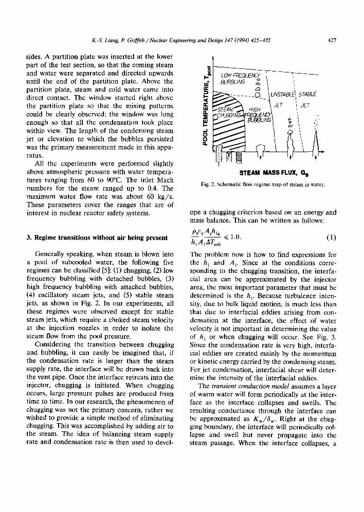
The problem now is how to find expressions for the h i and A i. Since at the conditions corre- sponding to the chugging transition, the interfa- cial area can be approximated by the injector area, the most important parameter that must be determined is the h i. Because turbulence inten- sity, due to bulk liquid motion, is much less than that due to interfacial eddies arising from con- densation at the interface, the effect of water velocity is not important in determining the value of h i or when chugging will occur. See Fig. 3. Since the condensation rate is very high, interfa- cial eddies are created mainly by the momentum or kinetic energy carried by the condensing steam. For jet condensation, interfacial shear will deter- mine the intensity of the interfacial eddies.
The transient conduction model assumes a layer of warm water will form periodically at the inter- face as the interface collapses and swells. The resulting conductance through the interface can be approximated as K w / 8 w. Right at the chug- ging boundary, the interface will periodically col- lapse and swell but never propagate into the steam passage. When the interface collapses, a
428 K.-S. Liang, P. Griffith / Nuclear Engineering and Design 147 (1994) 425-435
thermal layer will form at the injector as a result of the steam which is condensed. Right after the interface has collapsed, the steam flow causes it to swell again. The swelling interface then pushes the hot liquid away from the injector and the cycle starts again. To determine the resulting thermal layer thickness, we need to know the characteristic size of the bubble formed at the injector. If that bubble is scaled by the injector diameter, then the characteristic period is fixed as well as the thermal layer thickness. Since the latent heat rejected from the collapsing interface will be dumped into the surrounding water, the following energy equation can be written for de- termining the conduction layer thickness:
AT ~- h f g p y b = Cp--~-pf~ D26w. (2)
In this equation V 0 is the collapsed bubble vol- ume for each period. This volume is assumed to be characterized by the injector size, that is V b = cDi ~. From Eq. (2) we can derive an expression for the thermal layer thickness in the water 6 w. That is
6 w = C D J J a . (3)
As a result, the h i corresponding to the con- duction layer of warm water can be expressed as h i ¢~ J a . k / D i. Substituting the expression of h i
100(300 -
n - 8o000
G) J~
E 60000 z
e- 40o00
a) n-
20000 Ca
• Ja~107
• Ja -g2
• Ja=63
o Ja=24
0 I I I " I " I "
0 .00 0 .02 0 .04 0 .06 0 .06 010 0 .12
Steam Mach Number, M
Fig. 3. Effect of the water velocity of the chugging transition.
3 .
c.
VJ
2 -
0
DJ = 0 .0191 rn I
Bubbling & Jetting
.=
_. ' , _.=.:,..._ . . . . '%= IP
Chugging
-1 , , , , , • , •
20 40 60 80 1 oo 1 20 140
Water Jacob Number, Ja
Fig. 4. Criterion for the chugging transition.
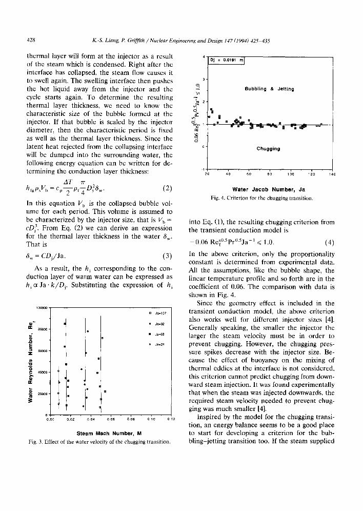
into Eq. (1), the resulting chugging criterion from the transient conduction model is
- 0 . 0 6 Re~°SPr°SJa-1 ~< 1.0. (4)
In the above criterion, only the proportionality constant is determined from experimental data. All the assumptions, like the bubble shape, the linear temperature profile and so forth are in the coefficient of 0.06. The comparison with data is shown in Fig. 4.
Since the geometry effect is included in the transient conduction model, the above criterion also works well for different injector sizes [4]. Generally speaking, the smaller the injector the larger the steam velocity must be in order to prevent chugging. However, the chugging pres- sure spikes decrease with the injector size. Be- cause the effect of buoyancy on the mixing of thermal eddies at the interface is not considered, this criterion cannot predict chugging from down- ward steam injection. It was found experimentally that when the steam was injected downwards, the required steam velocity needed to prevent chug- ging was much smaller [4].
Inspired by the model for the chugging transi- tion, an energy balance seems to be a good place to start for developing a criterion for the bub- bling-jetting transition too. If the steam supplied
K.-S. Liang, P. Griffith / Nuclear Engineering and Design 147 (1994) 425-435 429
cannot be removed through a bubble interface, this bubble then will enlarge until a larger inter- facial area is achieved and the energy and mass fluxes are once again in balance. Experimentally we observed that when a bubble begins to elon- gate, an axial interface oscillation always accom- panies it. As depicted in a high speed movie, it was found that each of the axial oscillations result from the detachment of an enlarged bubble. The idea of energy balance can be used to express the bubbling-jetting transition. That is:
psvsAjhfg rrD2hiATsu b >~ 1.0, (5)
where D d is the maximum stable bubble size attached to the injector. To a first approximation, D b can be determined from a balance between the surface tension force and the buoyancy force [6]. To find an adequate expression for the h i at the bubbling-jetting transition, the two-layer tur- bulent eddy transfer model [7] is used. To use the two-layer eddy transfer model, we need to know the characteristics of the eddies at the surface of the largest stable bubble. Since at the bubbling- jetting transition, the integral eddy scale still can be characterized by the injector size, the most important characteristic to be determined is the turbulence intensity around the interface. Conse- quently, the turbulence intensity can be related to the steam velocity as:
u, PsVs(~t: S )A,. (6) p f Z ( ~ w A i ) = 1 ,2
The term, pf(Ut3/At,) in the above equation is the turbulent energy dissipation rate per unit volume around the interface. It is provided by the kinetic energy carried by the condensing steam flow to the interface. From existing knowledge of free turbulence, it is recognized that the integral eddy size is about 1 /5 of the layer thickness [8]. There- fore, the u t is directly proportional to the vs by a factor of 1.4 (ps/pf) t/3. The final form of the criterion for jetting is:
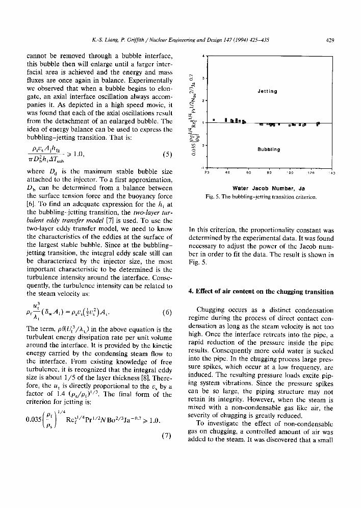
/ p \1/4 0.035[ ~'f J Re~l/4pr'/ZNBoZ/3ja-°7 >~ 1.0.
\Ps i (7)
o 3
Z 2 ¸
2 0
m g manm~
Jetting
am ~ m naem o r # 0"
B u b b l i n g
I * I l I l I " I
4 0 60 8 0 100 120 140
Water Jacob Number, Ja
Fig. 5. The bubbling-jetting transition criterion.
In this criterion, the proportionality constant was determined by the experimental data. It was found necessary to adjust the power of the Jacob num- ber in order to fit the data. The result is shown in Fig. 5.
4. Effect of air content on the chugging transition
Chugging occurs as a distinct condensation regime during the process of direct contact con- densation as long as the steam velocity is not too high. Once the interface retreats into the pipe, a rapid reduction of the pressure inside the pipe results. Consequently more cold water is sucked into the pipe. In the chugging process large pres- sure spikes, which occur at a low frequency, are induced. The resulting pressure loads excite pip- ing system vibrations. Since the pressure spikes can be so large, the piping structure may not retain its integrity. However, when the steam is mixed with a non-condensable gas like air, the severity of chugging is greatly reduced.
To investigate the effect of non-condensable gas on chugging, a controlled amount of air was added to the steam. It was discovered that a small
430 K.-S. Liang, P. Griffith / Nuclear Engineering and Design 147 (1994) 425-435
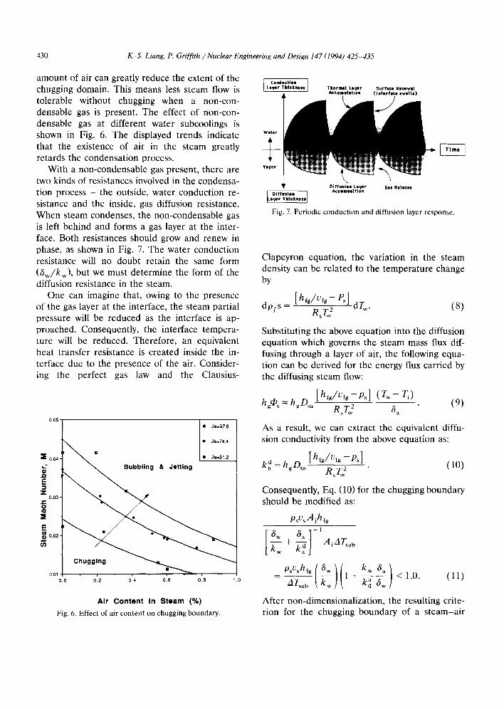
amount of air can greatly reduce the extent of the chugging domain. This means less steam flow is tolerable without chugging when a non-con- densable gas is present. The effect of non-con- densable gas at different water subcoolings is shown in Fig. 6. The displayed trends indicate that the existence of air in the steam greatly retards the condensation process.
With a non-condensable gas present, there are two kinds of resistances involved in the condensa- tion process - the outside, water conduction re- sistance and the inside, gas diffusion resistance. When steam condenses, the non-condensable gas is left behind and forms a gas layer at the inter- face. Both resistances should grow and renew in phase, as shown in Fig. 7. The water conduction resistance will no doubt retain the same form (6w/kw), but we must determine the form of the diffusion resistance in the steam.
One can imagine that, owing to the presence of the gas layer at the interface, the steam partial pressure will be reduced as the interface is ap- proached. Consequently, the interface tempera- ture will be reduced. Therefore, an equivalent heat transfer resistance is created inside the in- terface due to the presence of the air. Consider- ing the perfect gas law and the Clausius-
0.05
•0.04 ! Z O.03
x
E 0 . 0 2
0.01 0.0
m Ja-g7.6
• Ja=74.4
~ u b b l i n g & Jetting
i •
0.2 0,4 0.6 0.8
Air Content In Steam (%) Fig. 6. Effect of air content on chugging boundary.
[.?':g:l;':.., ] Thermal Lauer Surface Reneval
&c©umualtion
Fig. 7. Periodic conduction and diffusion layer response.
Clapeyron equation, the variation in the steam density can be related to the temperature change by
[h,Jv,g-e,] dpfs = RsT~ 2 dT~. (8)
Substituting the above equation into the diffusion equation which governs the steam mass flux dif- fusing through a layer of air, the following equa- tion can be derived for the energy flux carried by the diffusing steam flow:
(re- hgqD s ~- hgDsa R~T2 6a (9)
As a result, we can extract the equivalent diffu- sion conductivity from the above equation as:
[h,g/vfg-Ps] k d = hgDsa RsT~ 2 (10)
Consequently, Eq. (10) for the chugging boundary should be modified a s :
psvsAihfg
+ A i Arsu b
- AT~u ~ ~ 1 + ~ - ~ - ~ <1.0 . (11)
After non-dimensionalization, the resulting crite- rion for the chugging boundary of a s team-air
K.-S. Liang, P. Griffith / Nuclear Engineering and Design 147 (1994) 425-435 431
mixture is:
- - 4
0.06 1 + k,] 6 w Re}°'Spr°'Sja-1 ~< 1.0. (12)
3 %- The proportionality constant should be the same ,,
t¢3 as the one for pure steam chugging since, when ~ . . . . there is no air present, the criterion should re- , . £ 2 duce to the form appropriate for pure steam ~ g chugging. In the above equation, we still have one - ' ~ iI unknown quantity, •a//6w . This quantity physi- . ~ cally indicates the ratio of the two layer thick- ~p%', nesses in the interface periodic motion. It can be + 0
directly related the air content in the steam. ~. From steam energy and air mass conservation :' principles, this ratio can be expressed as in (4):
6 a 1 Ps - - = - J a - - Xn if X n << 1 .0 . ( 1 3 ) ~w 2 Pa
Therefore, a final form of the criterion of chug- ging transient for s team-air mixture is:
kw ja ps D/__~s a 10.5 - - X n 0.06 l + k , ] 2 PaV "~-'w-w )
× Re}0.Spr0.~ja-1 ~< 1.0. (14)
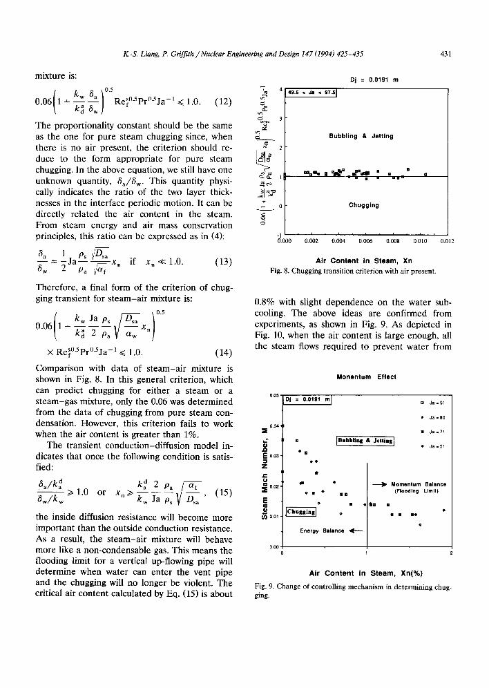
Comparison with data of s team-air mixture is shown in Fig. 8. In this general criterion, which can predict chugging for either a steam or a
0.05
steam-gas mixture, only the 0.06 was determined from the data of chugging from pure steam con- densation. However, this criterion fails to work 0.04 when the air content is greater than 1%. =
The transient conduction-diffusion model in- ® en
dicates that once the following condition is sates- E 003 feed: z
e-
~ a / k d ka d 2 Pa 0~ (15) ]o.o2 6 w / k w ~ 1.0 or x n ~ kw Ja Ps '
the inside diffusion resistance will become more ~ 00, important than the outside conduction resistance. As a result, the s team-air mixture will behave more like a non-condensable gas. This means the 000 flooding limit for a vertical up-flowing pipe will determine when water can enter the vent pipe and the chugging will no longer be violent. The critical air content calculated by Eq. (15) is about
Dj = 0 . 0 1 9 1 m
49.6 < Je < 97.51
B u b b l i n g & J e t t i n g
=%m= | ~ • _ f t l l = = [] q - m [] u w u m
C h u g g i n g
-1 i i , i i i 0 . 0 0 0 0 . 0 0 2 0.004 0 . 0 0 6 0 . 0 0 8 0 . 0 1 0 0 . 0 1 2
Ai r Conten t In S team, Xn Fig. 8. Chugging transition criterion with air present.
0.8% with slight dependence on the water sub- cooling. The above ideas are confirmed from experiments, as shown in Fig. 9. As depicted in Fig. 10, when the air content is large enough, all the steam flows required to prevent water from
M o n e n t u m E f f e c t
DJ = 0.0191 m I
[]
• []
• o
d •
o • • []m
o •
Energy B a l a n c e , IE - - -
] B u b b l i u . g & J e t t i n g ]
[] Ja = 91
• Ja = 80
I Ja=71
• Ja=51
• ~ M o m e n t u m Balance (Flooding L imi t )
t n I
I i Be
o
Ai r C o n t e n t In S t e a m , X n ( % )
Fig. 9. Change of controlling mechanism in determining chug- ging.
432 K.-S. Liang, P. Griffith / Nuclear Engineering and Design 147 (1994) 425-435
entering the steam vent pipe converge to a single value. The value can be determined from the flooding limit instead of an energy balance. The change of controlling mechanism indicates that the steam-air mixture now behaves more like an ordinary non-condensable gas. This suggests a means of suppressing chugging in systems that are prone to it.
5. Interfacial heat transfer of an osci l latory jet
From an analytical point of view, once we enter a flow regime, the information we most desire are the interfacial quantities, such as the interfacial area, the interfacial heat transfer coef- ficient, the interfacial friction factor, etc. How- ever, for direct contact condensation, the inter- face is always wavy and fuzzy unless either the water subcooling is low enough or the steam velocity is high enough. In these cases, the exact shape of the interface is difficult to determine. This is the reason why, for a regime like a sub- sonic oscillatory jet, quantitative interfacial infor- mation is quite skimpy. In our research, without separately determining the interracial area we have developed a methodology to systematically generate information on the product of the local- ized interracial area and the heat transfer coeffi- cient, (h i • a~)z, for the subsonic jetting regime.
For the oscillatory jets, the trends for the average heat transfer coefficient are in good agreement with that of a sonic jet [9]; pool sub- cooling has a larger effect than the exit steam velocity on the interracial heat transfer coeffi- cient, although the magnitudes are five to ten times smaller than they are for the sonic jets. In any case, an overall heat transfer correlation for the subsonic jet has not been developed yet. To deal with subsonic oscillatory jets, a special func- tion was defined, namely the integral condensa- tion distribution function. With this function, one can relate the product of the ( h i . a i) z to the system operating specifications, like the pool wa- ter temperature, s tream injection flow rate and geometry. This function is defined as:
, ( z ) = fZmc.z dz/rh . (16) -'o
02"
0.0 0 .0
$
1.2
B. lO
OB ' JO .m
a ~ ¢ 0 . 6 -
0 . 4 -
3
I [ r I r [ '
012 0, 0+ 08 ,0 ,2
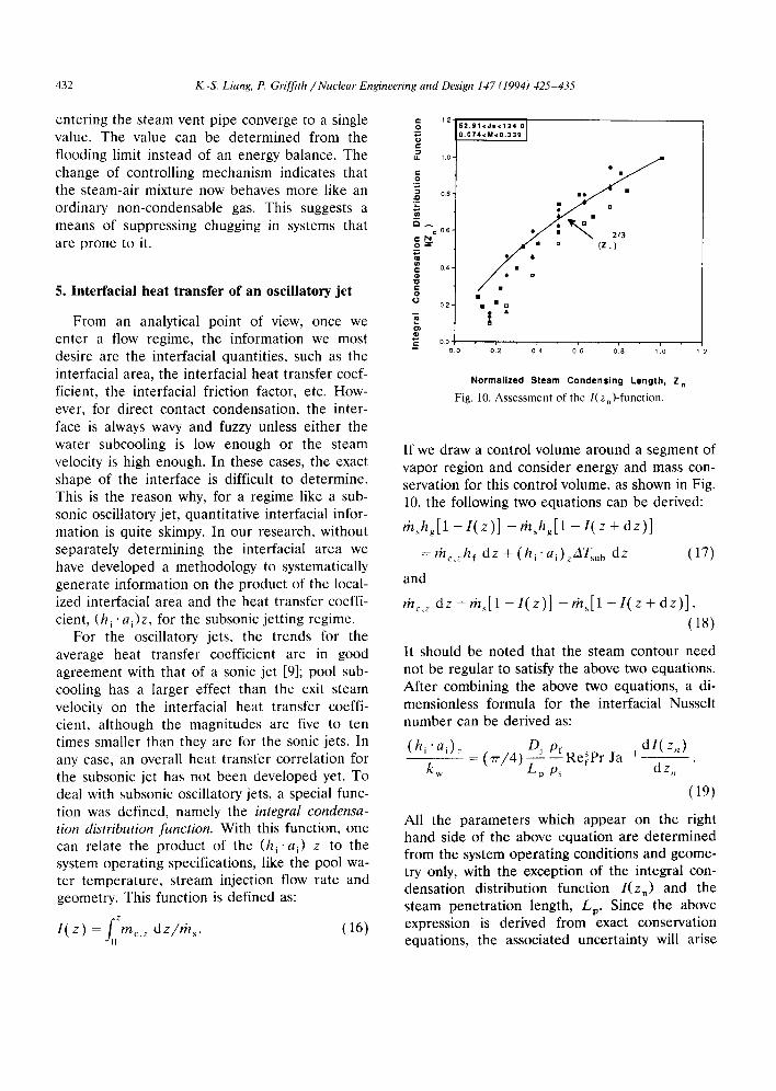
Normalized Steam Condensing Length, Z r,
Fig. 10. Assessment of the l(zn)-function.
If we draw a control volume around a segment of vapor region and consider energy and mass con- servation for this control volume, as shown in Fig. 10, the following two equations can be derived:
rh~h~[1 - I ( z ) ] - rh+hg[1 - l ( z + dz) ]
= t h c , z h f dz + (h i "ai )zATsu b d z (17)
and
rhc,~ d z = r h + [ 1 - 1 ( z ) ] - r h s [ 1 - 1 ( z + d z ) ] .
(18)
It should be noted that the steam contour need not be regular to satisfy the above two equations. After combining the above two equations, a di- mensionless formula for the interfacial Nusselt number can be derived as:
( h i ' a i ) z Dj d l ( z , , ) o+, ' R e ~ P r J a l
k ~ - (77" /4) LZ P~ dz,,
(19)
All the parameters which appear on the right hand side of the above equation are determined from the system operating conditions and geome- try only, with the exception of the integral con- densation distribution function / ( z n) and the steam penetrat ion length, Lp. Since the above expression is derived from exact conservation equations, the associated uncertainty will arise
K.-S. Liang, P. Griffith / Nuclear Engineering and Design 147 (1994) 425-435 433
only from the specification of the I(Z n) and the Lp. Basically, the derivative of the I ( z . ) will determine the relative distribution of the (h i • ai)z , and the Lp will determine the magnitude of the (h i ' a i )z . Since there are some correlations available for calculating the steam penetration length of subsonic jets, the desired local informa- tion of (h i • ai)z can be directly specified once we can have an adequate expression of I (z . ) .
Considering the integral condensation distri- bution function, it is believed that similarity might appear in the form of this function for a given characteristic regime, if we can find an adequate dimensionless length scale to describe it. To de- rive the form of I (z n) for oscillatory jets from Eq. (14), we will utilize the two-layer turbulent eddy transfer model [7] to represent the local interfa- cial heat transfer coefficient. The resulting equa- tion for the I(z n) will be:
d / ( z n ) ai,n ( Ut,zAt,z ) O'v5 dzn 0.25 ht,z ~ u----~
[" . Dj pf s x Pr °51(~ ' /4) - - - - Ref
[ Lp Ps Pr Ja -1 ] -1
(20)
M E A S U R E M E N T A N D P R E D I C T I O N
SO
E
4o
30
e"
10
Cl Ja=112 .4 , M=0 .339
• Ja=69 .4 , M=0 .082
B
to m - - Theoret ica l
o12 0h 01~ oi~ 0
0 .0 1 0
Normalized Steam Condensing Length, Z n
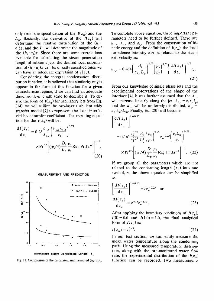
Fig. 11. Comparison of the calculated and measured (hi.a i)z.
To complete above equation, three important pa- rameters need to be further defined. These are ut, z, At, z and ai, z. From the conservation of ki- netic energy and the definition of I(Zn), the local turbulence intensity can be related to the steam exit velocity as:
( / i ) 1 / 3 ( l / 3 ( d i ( Z n ) ) l / 3 .=o464ai+ "
(21)
From our knowledge of single phase jets and the experimental observations of the shape of the interface [4], it was further assumed that the At, z will increase linearly along the jet, ht,z = C~Znlp, and the ai, z will be uniformly distributed, ai, z = c2Aj/Ljp. Finally, Eq. (20)will become:
dI(Zn)dz. ] 1-0'25
0.25 ~ 0.75 c20+ j( ) Zn0+I , =0"141c°'2------g L 2 pff ~ v---~--
Of Re Pr Ja -1 (22) x P r ° '
If we group all the parameters which are not related to the condensing length (z n) into one symbol, c, the above equation can be simplified as:
dl ( Zn) ]l-°'25 = CZn°'25 or
dzn ]
_ _ _ c4/3z~ 1/3. (23) dz n
After applying the boundary conditions of I(Zn), I(0) = 0.0 and 1(1.0)= 1.0, the final analytical form of I(z n) is:
I (Zn) = Z 2/3. (24)
In our test section, we can easily measure the mean water temperature along the condensing path. Using the measured temperature distribu- tion, along with the pre-monitored water flow rate, the experimental distribution of the I(Zn) function can be recorded. Two measurements

434 K.-S. Liang, P. Griffith / Nuclear Engineering and Design 147 (1994) 425-435
were made to determine the value of this func- tion, the length of the condensing steam plume, and the temperature of the water at several axial locations along the plume. These measurements are detailed in ref. [4] along with pictures of the plumes in various regimes. The comparison be- tween Eq. (24) and experimental integral conden- sation distribution functions are shown in Fig. 11. It is clear that Eq. (24) matches the data quite well.
Using Eq. (19) along with the derived integral condensation distribution function, /(Zn), and providing the total penetration length is given, we can calculate directly the product of the local interfacial heat transfer coefficient and interfacial area per unit length, (h i "ai)z. To evaluate this quantity, we utilize the condensation distribution measured from each experiment and generate the experimental (h i .ai) z. The comparison between measured and calculated value of ( h i ' a i) is shown in Fig. 12. It should be noted that the L o used in our calculations is obtained directly from our experimental measurements. In applications, the steam penetration length can be obtained from published correlations [10,11]. It can be seen that Eq. (19) not only can predict the distribution of (h i .ai)z, but also reflects the expected depen- dence on the water subcooling. Generally speak- ing, the magnitude of the h~ for steam jets in- creases primarily with the water subcooling.
6. Conclusions
As mentioned at the beginning, the primary objective of this research is to improve our under- standing and analysis capability for direct contact condensation of steam in water. Regimes associ- ated with the injection of steam into water have been investigated. Transition criteria between several important regimes have been proposed: a chugging transition criterion from the transient conduction model and a jetting transition crite- rion from the two-layer eddy transfer model Em- phasis has been put on the effects of non-con- densable gas on the chugging boundary. A tran- sient conduction-diffusion model has been devel-
oped to take into account the presence of non- condensable gas in steam. This model can also reasonably predict how much non-condensable gas is required to suppress chugging. In addition, the interracial heat transfer in the regime of oscillatory jets has also been studied, and a methodology is suggested for calculating the product of the interracial area and the heat trans- fer coefficient. In the proposed method, only the steam penetration length and the integral con- densation distribution function need to be speci- fied separately. Moreover, a general form of the integral condensation distribution function has been derived for subsonic oscillatory jets, which can be used to specify the relative distribution of ( h i " a i ) z for an oscillatory jet.
Since the effect of buoyancy on turbulent mix- ing is important when the velocity is not high enough, all the models developed for chugging transition are limited to upward steam injection. Those include the transient conduction model for the dry steam chugging and the transient conduc- tion-diffusion model for the chugging of s team- gas mixture. For the models associated with mix- ing of a steam jet, in water including Eq. (19) and the integral condensation distribution function, the orientation effect is not important.
The range of validity of the equations is cer- tainly encompasses the range of data which is described here. This range is shown on the fig- ures, and in the section under experiments. How- ever, as the equations have a physical basis too, they are expected to be valid outside that range as well. In fact, because the limiting heat transfer process is the turbulent transport in the liquid, it is anticipated that the models are appropriate whenever there is sufficient subcooling to con- dense all the steam.
In dimensionless terms the range of variables tested in these experiments is:
0 < M < 0 . 4 ,
10,000 < Ref < 90,000,
2 < P r < 8 ,
p f / p g = 1500,
24 < Ja < 107.
K.-S. Liang, P. Griffith / Nuclear Engineering and Design 147 (1994) 425-435 435
7. Nomenclature
a i A i Aj c
C 1 , C 2 Cp
D b
Dsa
hfg hi
J a
kw
Lp
M mc,z
m s
Pr Ref Re~
n s Ti
A Ts.b Ut
Uf
Us
X
Xn
interfacial area per unit length (m2/m), interfacial area (m2), injector area (m2), constant defined in Eq. (23), constants (dimensionless), liquid specific heat (J/kgK), max. bubble diameter (m), mass diffusion coefficient of steam through a medium of air (m2/s), injector diameter (m), latent heat of vaporization (kJ/kg), interfacial convection coefficient (Watt- / m 2" K), Jacob number, pwcpAT/pshfg, water conductivity (Watt /m • K), diffusion-equilibrium thermal conduc- tivity of air (Watt /m • K), steam penetration length (m), steam Mach number, VJVc, localized condensation flow per unit length (kg/ms), steam mass flow rate (kg/s), Bond number, gR2(pf - ps)tr, steam pressure (N/m2), Prandtl number, tZcp/k of the liquid, liquid Reynolds number, vfAh/vf, steam-liquid Reynolds number, vsDi/ /-'f, steam gas constant (N m / k g K), interface temperature (K), steam-air mixture temperature away from the interface (K), water subcooling (K), turbulent intensity (m/s), bubble size (m3), liquid velocity (m/s), steam velocity at the exit of the vent pipe (m/s), steam quality, content of noncondensable gas,
Z
Zn
Vf
Pa
Pf
Ps A t
~w ~a
6s
condensation length (m), normalized condensation length, z/Lp, kinematic viscosity (m2/sec) of the liq- uid, density of air (kg/m3), density of liquid (kg/m3), density of vapor (kg/m3), integral eddy size (m), water thermal layer thickness (m), air diffusion layer thickness (m), steam diffusion mass flux (kg/m 2. s).
References
[1] S.G. Bankoff, Some condensation studies pertinent to LWR safety, Int. J. of Multiphase Flow, 6 (1980) 51-57.
[2] K.E. Carlson, R.A. Riemke, et al., RELAP5/MOD3 Code Manual, NUREG/CR-5535, EGG-2569 (June 1990).
[3] Los Alamos National Laboratory, TRAC-PF1/MOD1. An Advanced Best Estimate Computer Program for Pressurized Water Reactor Thermal Hydraulic Analysis, LA-10157-MS, NUREG/CR-3558 (July 1986).
[4] K.-S. Liang, Experimental and analytical study of direct contact condensation of steam in water, Ph.D. Thesis (MIT) (May 1991).
[5] C.K. Chan and C.K.B. Lee, A Regime Map for Direct Contact Condensation, Int. J. Multiphase Flow, vol. 8, no. 1, pp. 11-20, 1982.
[6] G.B. Wallis, One-Dimensional Two-Phase Flow (Mc- Graw-Hill, Inc., 1969).
[7] T.G. Theofanous, R.N. Houze and L.K. Bumfield, Tur- bulent mass transfer at free gas-liquid interface with application to open channel, bubble and jet flows, Int. J. Heat Mass Transfer 19 (1976) 613-624.
[8] J.T. Davies, Turbulence Phenomena (Academic Press, 1972).
[9] M.E. Simpson and C.K. Chen, Hydrodynamics of a sub- sonic vapor jet in subcooled liquid, J. of Heat Transfer 104 (May 1982) 271-278.
[10] V.L. Ysachenko, A.P. Solodov and V.V. Sennikow, Heat transfer with condensation of a steam jet in a liquid flow, Teploenergetika 26 (1979) 20-23.
[11] A. Kudo, T. Egnsa and S. Toda, Basic study on vapor suppression, The Fifth International Heat Transfer Con- ference, Vol. 3, (1974) pp. 226-230.