Determination of the Tool–Chip Contact Length for the Cutting ...
17
Citation: Storchak, M.; Drewle, K.; Menze, C.; Stehle, T.; Möhring, H.-C. Determination of the Tool–Chip Contact Length for the Cutting Processes. Materials 2022, 15, 3264. https://doi.org/10.3390/ma15093264 Academic Editors: Arash Soleiman-Fallah and Bin Wang Received: 7 April 2022 Accepted: 29 April 2022 Published: 2 May 2022 Publisher’s Note: MDPI stays neutral with regard to jurisdictional claims in published maps and institutional affil- iations. Copyright: © 2022 by the authors. Licensee MDPI, Basel, Switzerland. This article is an open access article distributed under the terms and conditions of the Creative Commons Attribution (CC BY) license (https:// creativecommons.org/licenses/by/ 4.0/). materials Article Determination of the Tool–Chip Contact Length for the Cutting Processes Michael Storchak * , Konstantin Drewle, Christian Menze, Thomas Stehle and Hans-Christian Möhring Institute for Machine Tools, University of Stuttgart, Holzgartenstraße 17, 70174 Stuttgart, Germany; [email protected] (K.D.); [email protected] (C.M.); [email protected] (T.S.);[email protected] (H.-C.M.) * Correspondence: [email protected]; Tel.: +49-711-685-83831 Abstract: The thermomechanical interaction of the tool with the chip in the most loaded secondary cutting zone depends on the contact length of the tool rake face with the chip. Experimental studies of the dependency of the contact length on the cutting speed, the undeformed chip thickness, and the tool rake angle, performed by the optical method, are used for comparison with the contact length obtained by the FE modeling of the orthogonal cutting process. To determine the parameters of the constitutive Johnson–Cook equation, which serves as a material model of the FE cutting model that has a predominant influence on the contact length, a software-implemented algorithm was developed. This algorithm is based on determining the generalized parameters of the constitutive equation through finding the intersection of these parameter sets. The plurality intersection of the parameter sets of the constitutive equation is determined by means of the design of experiments and refined by subsequent multiple iterations. The comparison of the contact length values, obtained by simulating the cutting process using the generalized parameters of the constitutive equation as a material model with their experimental values, does not exceed 12% for a wide range of cutting speeds and depths of cut, as well as for the tool rake angle. Keywords: cutting; contact length; FE cutting model; simulation; constitutive equation parameters 1. Introduction Cutting is one of the most common processes for forming various products. The cutting process is manifested externally by different physical quantities that can characterize the process. The most important characteristics of the cutting process are the thermomechanical properties of the process, such as the forces and temperatures, the chip morphology, and the chip compression value, as well as the micro-geometry and the physical–mechanical parameters of the machined material surface. The cutting process is externally expressed by various physical quantities that can characterize the process. The most important characteristics of the cutting process are the thermomechanical properties [1–3], such as the forces and temperatures, the chip morphology, and the chip compression value, as well as the micro-geometry and the physical–mechanical parameters of the machined material surface. These quantities are generally used to determine the state of the cutting process. In addition to the properties of the technological system that realize the cutting process, the contact parameters between the tool, chip and workpiece also define the cutting process. An important contact characteristic is the contact length between the rake face of the tool and the chip, which determines the interaction in the secondary cutting zone, e.g., the friction and heat transfer between the tool and the chip. The contact length has a complex relationship with the parameters and conditions of the cutting process, the thermomechanical properties of the machined material, the cutting tool geometry, and others. Due to the complexity of these relationships, it is not yet possible to analytically determine the contact length between the rake face of the tool and the chip. Simultaneously, Materials 2022, 15, 3264. https://doi.org/10.3390/ma15093264 https://www.mdpi.com/journal/materials
-
Upload
khangminh22 -
Category
Documents
-
view
2 -
download
0
Transcript of Determination of the Tool–Chip Contact Length for the Cutting ...

Citation: Storchak, M.; Drewle, K.;
Menze, C.; Stehle, T.; Möhring, H.-C.
Determination of the Tool–Chip
Contact Length for the Cutting
Processes. Materials 2022, 15, 3264.
https://doi.org/10.3390/ma15093264
Academic Editors: Arash
Soleiman-Fallah and Bin Wang
Received: 7 April 2022
Accepted: 29 April 2022
Published: 2 May 2022
Publisher’s Note: MDPI stays neutral
with regard to jurisdictional claims in
published maps and institutional affil-
iations.
Copyright: © 2022 by the authors.
Licensee MDPI, Basel, Switzerland.
This article is an open access article
distributed under the terms and
conditions of the Creative Commons
Attribution (CC BY) license (https://
creativecommons.org/licenses/by/
4.0/).
materials
Article
Determination of the Tool–Chip Contact Lengthfor the Cutting ProcessesMichael Storchak * , Konstantin Drewle, Christian Menze, Thomas Stehle and Hans-Christian Möhring
Institute for Machine Tools, University of Stuttgart, Holzgartenstraße 17, 70174 Stuttgart, Germany;[email protected] (K.D.); [email protected] (C.M.);[email protected] (T.S.); [email protected] (H.-C.M.)* Correspondence: [email protected]; Tel.: +49-711-685-83831
Abstract: The thermomechanical interaction of the tool with the chip in the most loaded secondarycutting zone depends on the contact length of the tool rake face with the chip. Experimental studiesof the dependency of the contact length on the cutting speed, the undeformed chip thickness, and thetool rake angle, performed by the optical method, are used for comparison with the contact lengthobtained by the FE modeling of the orthogonal cutting process. To determine the parameters ofthe constitutive Johnson–Cook equation, which serves as a material model of the FE cutting modelthat has a predominant influence on the contact length, a software-implemented algorithm wasdeveloped. This algorithm is based on determining the generalized parameters of the constitutiveequation through finding the intersection of these parameter sets. The plurality intersection of theparameter sets of the constitutive equation is determined by means of the design of experiments andrefined by subsequent multiple iterations. The comparison of the contact length values, obtainedby simulating the cutting process using the generalized parameters of the constitutive equation asa material model with their experimental values, does not exceed 12% for a wide range of cuttingspeeds and depths of cut, as well as for the tool rake angle.
Keywords: cutting; contact length; FE cutting model; simulation; constitutive equation parameters
1. Introduction
Cutting is one of the most common processes for forming various products. The cuttingprocess is manifested externally by different physical quantities that can characterize theprocess. The most important characteristics of the cutting process are the thermomechanicalproperties of the process, such as the forces and temperatures, the chip morphology, andthe chip compression value, as well as the micro-geometry and the physical–mechanicalparameters of the machined material surface. The cutting process is externally expressedby various physical quantities that can characterize the process. The most importantcharacteristics of the cutting process are the thermomechanical properties [1–3], such asthe forces and temperatures, the chip morphology, and the chip compression value, aswell as the micro-geometry and the physical–mechanical parameters of the machinedmaterial surface. These quantities are generally used to determine the state of the cuttingprocess. In addition to the properties of the technological system that realize the cuttingprocess, the contact parameters between the tool, chip and workpiece also define the cuttingprocess. An important contact characteristic is the contact length between the rake faceof the tool and the chip, which determines the interaction in the secondary cutting zone,e.g., the friction and heat transfer between the tool and the chip. The contact length hasa complex relationship with the parameters and conditions of the cutting process, thethermomechanical properties of the machined material, the cutting tool geometry, andothers. Due to the complexity of these relationships, it is not yet possible to analyticallydetermine the contact length between the rake face of the tool and the chip. Simultaneously,
Materials 2022, 15, 3264. https://doi.org/10.3390/ma15093264 https://www.mdpi.com/journal/materials

Materials 2022, 15, 3264 2 of 17
the contact length is used as a reference value in many analytical cutting models; see,e.g., [1,4,5]. Furthermore, the contact length is used as a verification value of simulationresults for the numerical cutting models. It can serve as a reference point for evaluatingthe correct selection of parameters of the constitutive equation and the parameters of thefriction model for use in the numerical cutting models. Determining the contact lengthbetween the rake face of the tool and the chip is, therefore, an important issue, and solving itwill improve the accuracy and validity of the modeling results of various cutting processes.This paper deals with experimental and simulative studies to determine the contact lengthfor further use in analytical and numerical cutting models.
2. Methods for the Determination of Contact Length
The cutting process takes place under complex deformation and contact interactionsbetween the tool and the workpiece. The length of the chip–tool interaction in the directionof flow is called the natural contact length [6]. Within this contact length, there are manythermomechanical interactions between the rake face of the cutting tool and the chip [1,3].Because of this, a heat flow occurs, which is why the natural contact length has a significantinfluence on the resulting tool temperature [7]. An increased temperature accelerateschemical reactions, abrasive wear, and diffusion, which in turn increase tool wear [6,8–10].Therefore, the theoretical and experimental description or investigation of the naturalcontact length has a long historical development, and the major part of the investigationspresented in the literature to determine the contact length are carried out within theframework of a fundamental understanding of the cutting process as well as the tribologicalaspects, such as the friction and wear between the tool and chip [11–14]. Lee and Shaffer [15]derived an equation for the determination of the natural contact length, considering theuncut chip thickness, the shear angle, and the rake angle. Abuladze [16] developed a modelof the contact length dependence on the uncut chip thickness, the shear angle, and thecompression ratio. Bhattacharyya [17] used natural contact length and controlled-contactcutting tools to explain the character of the influence of a small amount of lead on themetallic friction phenomenon in the cutting process. In [18], the cutting studies showedthat when cutting aluminum alloy, a tool force existed which did not act on the tool rakeface but the tool nose. The results indicate that this force was independent of the depthof cut, the chip–tool contact length, and the chip thickness, under the cutting conditionsinvestigated. Poletika [19] conducted several experiments on various metals, such ascarbon, stainless steel, copper, and bronze, and found a unique relation between the chipthickness coefficient and the total contact length. Friedmann and Lenz [20] showed intheir experiments that contact length and chip curl are affected by many parameters in thecutting system, and the influence of a single parameter is very difficult to isolate. Moreover,they concluded that their results support the hypothesis that contact length and chip curlvariation are governed by the temperature field. Kato et al. [21], using the split tool method,reported that the contact length is twice the deformed chip thickness.
The natural contact length lC is divided into two areas where different contact condi-tions exist [3,5,19]: the plastic area and the elastic area. The first area is characterized by aplastic deformation process [3,22]. In the second area, an elastic frictional interaction takesplace [3,6].
The natural contact length is the causal result of complex thermomechanical mech-anisms and a variety of influencing factors. An investigation of the contact length cantherefore only be carried out relatively. The methods and models developed in recentdecades for determining the contact length of the tool rake face with the chip can bedivided into three main areas:
• Experimental study;• Analytical models;• Numerical simulation.
The experimental measurements of contact length were generally performed by opticalmethods. Analyzing electron microscope photographs, Balaji and colleagues evaluated the

Materials 2022, 15, 3264 3 of 17
contact length between the tool rake face and the chip in the sliding and sticking zones forgrooved tools [10]. The dependence of the contact length on the tool’s thermal conductivitycoefficient was established. Grzesik and Nieslony [23] measured the contact length by animprint on the tool rake face, formed as a result of the cutting process. The measurementswere performed using an optical image processing system for tools with different multilayercoatings. As a result, the dependence of the contact length on the cutting speed and thecutting temperature was obtained. Sutter’s study is devoted to measuring contact lengthduring cutting using video recording with a high-speed camera [24]. The contact length wasdetermined visually with a maximum error of 7%. The dependence of the contact length onthe cutting depth (undeformed chip thickness) and the chip compression coefficient wascompared with the calculated values of the contact length obtained by other authors.
Abukhshim et al., using an electron microscope, measured the contact length from themark left by the chip on the tool rake face as a result of the high-speed cutting process [25].The dependence of the contact length on the cutting speed at different values of tool wearwas obtained. The investigations show that previous analytical models cannot adequatelydescribe the contact length in HSM (high-speed cutting). Above 400 m/min, the naturalcontact length rises with the increasing cutting speed. Using a similar technique, Iqbalet al. studied the change in contact length as a function of cutting speed and undeformedchip thickness when cutting AISI 1045 steel and Ti6AlV4 titanium alloy [26]. The studiesby Heisel et al. showed that reducing the contact length by artificially manipulating therake face leads to a reduction in the cutting forces and a lowering of the chip compressionratio [27]. The reason for this is a shorter tribological chip–tool friction contact. This makesit possible to estimate the point at which the natural contact length is undercut. In [28],the authors used a Polyvar optical microscope to show that the machined material andthe cutting speed also have a significant influence on the contact length. The study of theinfluence of contact length on the stability of the cutting process of structural steel andaluminum alloy is devoted by Ojolo and Awe [29]. Based on the obtained dependence ofthe contact length on the feed rate, the stability of the process was analyzed, and ways toincrease it were indicated. The effect of ultrasonic vibration on the contact conditions of thetool rake face when cutting AISI 304 steel was studied by Amini and Kazemiyoun [30]. Thecontact length was determined by measuring the marks left by the chip on the tool rake face.Sadik und Lindström [31] considered the influence of artificially reduced contact lengths,with regard to the use of chip breaker grooves. The results showed that the technologicalcontact length setting should be between the natural contact length and the plastic area ofthe entire contact zone. Ortiz-de-Zarate et al. [32] used a tool with a square groove in therake face of the tool to adjust the contact length and to investigate the contact conditions inthe cutting process.
The studies devoted to determining the contact length of the tool rake face withthe chip by analytical methods occupy the major part of all research in this field. Themethodological basis of these studies is the cutting theory; see, e.g., [1,2,5,15,22,33]. Anoverview of the numerous models for calculating the contact length of the tool rake facewith chips and the expected trends in the development of the calculation models arepresented in a study by Fatima and Mativenga [34].
By forcing the restrictions on contact length through a reduction in the length ofthe tool rake face, Oxley determined the shear angle and friction angle [35]. Analyzingthe cutting process under these conditions, he predicted the dependence of the abovecharacteristics on changes in the contact length. Friedman and Lenz have shown that thecontact length is significantly influenced by the tool coating type with the constant basiccutting characteristics [20]. Chiffre and Wanheim proposed a mechanical model of chipformation that takes into account the stress distribution at the tool rake face [36]. This modelcan be the basis for the analytical calculation of the contact length. Poletika and Pushnykhconsidered two areas of contact length—plastic and elastic [37]. They proposed analyticalexpressions for determining the relative contact length for cutting processes with toolsequipped with carbide inserts. Many authors use the slip-line method to determine the

Materials 2022, 15, 3264 4 of 17
contact conditions between the tool rake face and the chip and, in particular, to determinethe contact length; see, e.g., [15,38–41]. Fang used this method to study chip morphologyduring milling [42]. Aseev and Sidorenko have proposed a new mathematical model forcalculating the total contact length and its plastic region [43]. The model is based on theassumption that chip shear occurs along the curve of the second order, which is confirmedexperimentally. A model for calculating contact using a genetic algorithm was proposed byZadshakoyan and Pourmostaghimi [44]. Evaluation of the tool–chip contact length for theorthogonal cutting process, using tools with multilayer coatings, is considered in a studyby Balaji and Mohan [45]. The proposed model is based on a combination of analyticaland empirical approaches and makes it possible to predict the contact length. Ozlu andhis colleagues developed an analytical two-zone model of orthogonal cutting [46]. Themodel predicts the contact length, which coincides reasonably well with the experimentalmeasurements. Ren et al. proposed a model for estimating contact length when cuttingTi6Al4V titanium alloy that takes into account the formation of segmented chips [47].
In the last few decades, studies have been carried out not only to simulate the maincharacteristics of the cutting process, such as the cutting force, cutting temperature, shearangle, chip compression coefficient, and chip morphology, but also to determine the con-tact length of the tool rake face with the chips through numerical models, mainly withFEM [48–50]. Semi-empirical models, such as the Johnson–Cook constitutive equation,have become the most popular for modelling different machining processes, due to theirsimplicity and capability in adequately describing flow curves in a wide variation range ofthe basic parameters. The Johnson–Cook constitutive equation represents, in a multiplica-tive form, the stress–strain relationship, which depends on five parameters [51]:
σS = (A + B · εn) ·[
1 + C · ln( .
ε.ε0
)]·[
1 −(
T − T0
Tm − T0
)m]where σs is the yield point, A is the initial yield stress, B is the stress coefficient of strainhardening, n is the power coefficient of strain hardening, C is the strain rate coefficient,m is the power coefficient of thermal softening, ε is the strain,
.ε is the strain rate,
.ε0 is the
reference value of the strain rate, T is the actual temperature, T0 is the reference or roomtemperature, and Tm is the melting temperature of the material.
Bil and colleagues, implementing the finite element method, compared the numericalsimulation results of the cutting process characteristics, including contact length, duringorthogonal cutting for various commercial programs. The calculation results showed goodagreement with the experimental data [52]. Analyzing various friction models in the con-tact of the tool rake face with chips by numerical simulation of the orthogonal cuttingprocess, Iqbal et al. showed a significant dependence of the contact length on the chosenscheme of friction distribution in the tool rake face [53]. The Coulomb friction model andthe sticking-sliding friction model were considered. Woon and colleagues analyzed thecontact length in the micro-cutting process numerically and experimentally [54]. Theyshowed good agreement between the values obtained by simulation and experimentalstudies using the optical method. Courbon et al. analyzed the thermal contact conditionsbetween the tool, chip, and workpiece during the dry-cutting of AISI 1045 steel throughnumerical simulation and experimental studies using optical, electron microscopy andenergy dispersive spectrometry methods [55]. The influence of the contact conductivityin the tool–chip pair on the contact length is shown. The authors recommend consideringthe average value of the contact length as significant fluctuations in the individual mea-surements of this value have been observed. Moreover, it was shown that the use of ahigh-pressure coolant resulted in a reduced natural contact length [56]. Kishawy and col-leagues developed a thermoelastic–viscoelastic finite element model to simulate 304 L steelorthogonal cutting [57]. They used this model to investigate the influence of the cuttingparameters and cutting tool geometry on the tool–chip contact conditions, particularly onthe contact length. A significant influence of the feed rate on the contact length of the tool
Materials 2022, 15, 3264 5 of 17
face with the chip was shown. In addition to the mere cutting investigation, numericalsimulations can also provide input variables for analytical approaches [58].
The current state of knowledge shows the long development of the investigation ofcontact length in the cutting process. The large number of influencing parameters makesthe simulative modeling of the contact length with the FEM very difficult. However, thesimulation-based investigation of the thermomechanical and kinetic processes in metalcutting, as well as an a priori prediction of tool wear, can only be carried out with thecorrect contact length. This paper shows an approach for the inverse adaptation of thecontact length in the simulation to the experimentally determined reference values in thecutting of AISI 1045.
3. Materials and Methods3.1. Materials
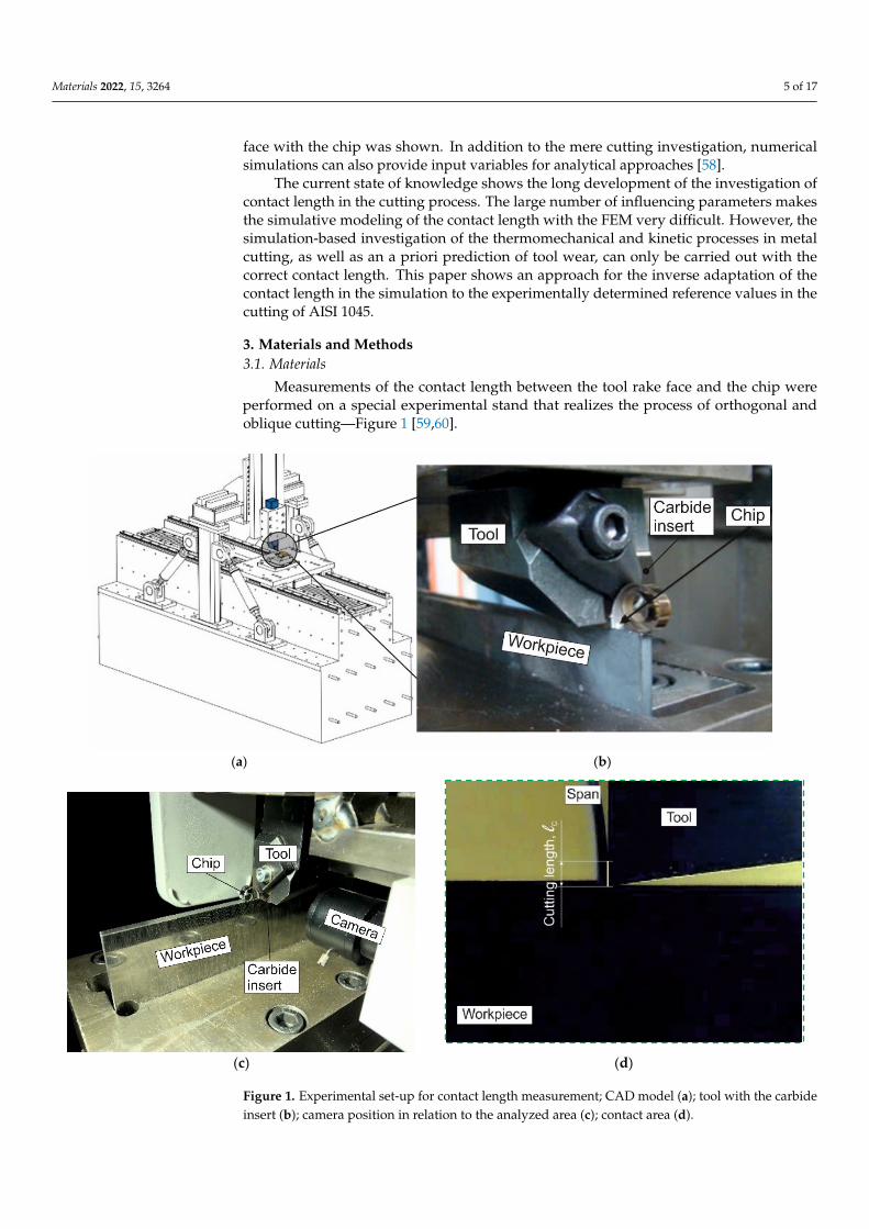
Measurements of the contact length between the tool rake face and the chip wereperformed on a special experimental stand that realizes the process of orthogonal andoblique cutting—Figure 1 [59,60].
Materials 2022, 15, x FOR PEER REVIEW 5 of 18
pressure coolant resulted in a reduced natural contact length [56]. Kishawy and colleagues developed a thermoelastic–viscoelastic finite element model to simulate 304 L steel or-thogonal cutting [57]. They used this model to investigate the influence of the cutting pa-rameters and cutting tool geometry on the tool–chip contact conditions, particularly on the contact length. A significant influence of the feed rate on the contact length of the tool face with the chip was shown. In addition to the mere cutting investigation, numerical simulations can also provide input variables for analytical approaches [58].
The current state of knowledge shows the long development of the investigation of contact length in the cutting process. The large number of influencing parameters makes the simulative modeling of the contact length with the FEM very difficult. However, the simulation-based investigation of the thermomechanical and kinetic processes in metal cutting, as well as an a priori prediction of tool wear, can only be carried out with the correct contact length. This paper shows an approach for the inverse adaptation of the contact length in the simulation to the experimentally determined reference values in the cutting of AISI 1045.
3. Materials and Methods 3.1. Materials
Measurements of the contact length between the tool rake face and the chip were performed on a special experimental stand that realizes the process of orthogonal and oblique cutting—Figure 1 [59,60].
(a) (b)
Materials 2022, 15, x FOR PEER REVIEW 6 of 18
(c) (d)
Figure 1. Experimental set-up for contact length measurement; CAD model (a); tool with the car-bide insert (b); camera position in relation to the analyzed area (c); contact area (d).
The CAD model of the experimental stand is shown in Figure 1a. The bed of the test stand is manufactured from solid polymer concrete. On the bed, there are slideways for moving the table with the workpiece. To measure the cutting forces on the workpiece side, it was clamped in a three-component dynamometer type 9121 from Kistler, which is lo-cated on the table. The linear motor provides the reciprocating motion of the table. The table movement speed with the workpiece is continuously adjustable from 0 to 200 m/min. This covers the conventional cutting speed range for most metals and alloys. The drive system consists of a linear motor, a servo control unit, including power electronics, and a computer as the control system.
The tool holder is fixed to the gantry structure connected to the bed. To increase the rigidity, the gantry with the tool is additionally connected to the bed using tension rods, the prestressing of which can be adjusted. This adjustment is made when it is necessary to change the stiffness of the experimental stand. The required cutting depth is ensured by adjusting the movement of the ram and the tool holder attached to it to an accuracy of 0.01 mm. SNMG-SM-1105 (ISO SNMG 15 06 12-SM 1105), Sandvik Coromant, Sandviken, Sweden interchangeable carbide inserts were used as a cutting element. The cutting wedge geometry required for cutting was provided by positioning the carbide insert in the tool body at a specified rake angle and grinding the tool’s clearance face. The tool’s clearance angle was 8°, and the radius of the cutting-edge rounding was 20 µm in all tests. A view of the tool with the carbide insert while cutting the workpiece is shown in Figure 1b.
Orthogonal cutting was performed on workpieces from AISI 1045 steel with a thick-ness of 3 mm, a length of 170 mm, and a height of 60 mm. To achieve the necessary geo-metric accuracy, the edges of the workpiece were pre-ground and polished [61,62]. To remove residual stresses, the workpiece was subjected to thermal annealing. After anneal-ing, the hardness of the workpiece was HB 1700–1750 MPa. The mechanical and thermal properties of this material are listed in Table 1.
Table 1. Mechanical and thermal properties of the steel AISI 1045 [63,64].
Strength (MPa) Elastic Modulus
(GPa)
Elongation (%)
Hardness (HB)
Poisson′s Ratio
Specific Heat (J/kg·K)
Thermal Ex-pansion
(µm/m·°C)
Thermal Conduc-tivity (W/m·K) Tensile Yield
690 620 206 12 180 0.29 486 14 49.8
Figure 1. Experimental set-up for contact length measurement; CAD model (a); tool with the carbideinsert (b); camera position in relation to the analyzed area (c); contact area (d).

Materials 2022, 15, 3264 6 of 17
The CAD model of the experimental stand is shown in Figure 1a. The bed of the teststand is manufactured from solid polymer concrete. On the bed, there are slideways formoving the table with the workpiece. To measure the cutting forces on the workpiece side,it was clamped in a three-component dynamometer type 9121 from Kistler, which is locatedon the table. The linear motor provides the reciprocating motion of the table. The tablemovement speed with the workpiece is continuously adjustable from 0 to 200 m/min. Thiscovers the conventional cutting speed range for most metals and alloys. The drive systemconsists of a linear motor, a servo control unit, including power electronics, and a computeras the control system.
The tool holder is fixed to the gantry structure connected to the bed. To increase therigidity, the gantry with the tool is additionally connected to the bed using tension rods,the prestressing of which can be adjusted. This adjustment is made when it is necessaryto change the stiffness of the experimental stand. The required cutting depth is ensuredby adjusting the movement of the ram and the tool holder attached to it to an accuracy of0.01 mm. SNMG-SM-1105 (ISO SNMG 15 06 12-SM 1105), Sandvik Coromant, Sandviken,Sweden interchangeable carbide inserts were used as a cutting element. The cutting wedgegeometry required for cutting was provided by positioning the carbide insert in the toolbody at a specified rake angle and grinding the tool’s clearance face. The tool’s clearanceangle was 8◦, and the radius of the cutting-edge rounding was 20 µm in all tests. A view ofthe tool with the carbide insert while cutting the workpiece is shown in Figure 1b.
Orthogonal cutting was performed on workpieces from AISI 1045 steel with a thicknessof 3 mm, a length of 170 mm, and a height of 60 mm. To achieve the necessary geometricaccuracy, the edges of the workpiece were pre-ground and polished [61,62]. To removeresidual stresses, the workpiece was subjected to thermal annealing. After annealing, thehardness of the workpiece was HB 1700–1750 MPa. The mechanical and thermal propertiesof this material are listed in Table 1.
Table 1. Mechanical and thermal properties of the steel AISI 1045 [63,64].
Strength (MPa) ElasticModulus
(GPa)
Elongation(%)
Hardness(HB)
Poisson’sRatio
SpecificHeat
(J/kg·K)
ThermalExpansion(µm/m·◦C)
ThermalConductivity
(W/m·K)Tensile Yield
690 620 206 12 180 0.29 486 14 49.8
The experimental studies were performed during dry orthogonal cutting. During theexperiments, three values of the tool rake angle were used: −10◦, 0◦, and 10◦. The cuttingprocess of the AISI 1045 steel was analyzed for varying cutting speeds and undeformedchip thicknesses (depth of cut). Varying the cutting speed from 30 m/min to 180 m/minand the depth of cut from 0.1 to 0.25 mm was implemented so that the Péclet similaritycriterion (Péclet number) [7,27] changed from ca. 5 to ca. 100.
3.2. Methods
The camera position in relation to the analyzed contact area of the tool rake face withthe chip is presented in Figure 1c. An example of a camera image from the contact area usedfor contact length analysis is shown in Figure 1d. The camera’s resolution provides multipleseparate images during a tool pass. The uncertainty in the contact length measurementarises mainly from the fluctuations of the chip during the cutting process. Because ofthis, the coordinates of the last point of chip contact with the tool face are constantlychanging. This uncertainty can be eliminated by repeating the measurements multipletimes. Repeating separate cuts multiple times (at least 5 times), together with the analysisof separate images of one cut, provided a measurement error in the contact length of thetool rake with the chip within 6–11%, depending on the cutting speed.

Materials 2022, 15, 3264 7 of 17
4. Results of Contact Length Experimental Measurement
The measurement results of the contact length between the tool rake and chip thatdepend on the cutting speed and depth of cut (undeformed chip thickness) and the cuttingwedge rake angle of the tool are shown in Figure 2. The contact length changes show asimilar character of dependence on the cutting speed and depth of cut for all three studiedtool rake angles. Thus, the contact length monotonically decreases with the increasing of thecutting speed. With the increase in cutting depth, the contact length increases monotonicallyfor all three values of the tool rake angle (see Figure 2a–c). The exception to this monotonicvariation is the contact length values at a cutting speed of 180 m/min. This is due todynamic phenomena when cutting with such high cutting speeds. At significant values ofthe cutting speed, the inertial properties of the chip are observed. As a result of inertialforces, the chip is pressed against the tool rake face, thereby increasing the contact length.
Materials 2022, 15, x FOR PEER REVIEW 8 of 18
(a) (b)
(c)
Figure 2. Contact length depends on cutting speed and depth of cut. (a) γ = −10°, (b) γ = 0°, (c) γ = 10°.
In addition to the dynamic behavior of the technological system, other factors have a significant influence on the contact length deviation, such as, in particular, the instability of the tool position relative to the machined surface caused by the spring back [65], and many others. This causes some uncertainty in the measurement of the contact length by optical methods. This uncertainty is eliminated by repeating measurements at each point of change in the cutting conditions and tool geometry.
To analyze the combined effect of the cutting parameters and the tool cutting wedge geometry on the contact length, it is necessary to present the studied results in the form of a generalized dependence.
The experimental results of the orthogonal cuts show that all three investigated var-iables have a decisive influence on the contact length between the chip and the tool. Due to these numerous influencing factors, it is reasonable to describe the relationship between the influencing variables of cutting speed, cutting depth (undeformed chip thickness), and tool rake angle and the target variable of the contact length with an empirical equation. A range of different approaches can be used for this purpose. Particularly suitable in this regard are those function types that calculate the target value as the product of several potency functions with the respective parameter in the base and an exponent.
Figure 2. Contact length depends on cutting speed and depth of cut. (a) γ = −10◦, (b) γ = 0◦, (c) γ = 10◦.
However, this results in relatively small deformation values of the machined material,which are achieved during cutting using tools with rake angles of 0◦ and 10◦. With largevalues of material deformation provided during cutting with a tool rake angle of −10◦
or higher, the chips formed are stronger and more stable. As a result, the stability ofthe chip prevails over the inertial forces. However, with a relatively low depth of cutand, consequently, a small chip thickness, the inertial forces prevail over the strength andstability of the chip formed during cutting with a tool rake angle of −10◦. This is indicated

Materials 2022, 15, 3264 8 of 17
by the increased contact length at a cutting speed of 180 m/min and a cutting depth of0.05 mm (see Figure 2a).
In addition to the dynamic behavior of the technological system, other factors have asignificant influence on the contact length deviation, such as, in particular, the instabilityof the tool position relative to the machined surface caused by the spring back [65], andmany others. This causes some uncertainty in the measurement of the contact length byoptical methods. This uncertainty is eliminated by repeating measurements at each pointof change in the cutting conditions and tool geometry.
To analyze the combined effect of the cutting parameters and the tool cutting wedgegeometry on the contact length, it is necessary to present the studied results in the form ofa generalized dependence.
The experimental results of the orthogonal cuts show that all three investigated vari-ables have a decisive influence on the contact length between the chip and the tool. Due tothese numerous influencing factors, it is reasonable to describe the relationship between theinfluencing variables of cutting speed, cutting depth (undeformed chip thickness), and toolrake angle and the target variable of the contact length with an empirical equation. A rangeof different approaches can be used for this purpose. Particularly suitable in this regardare those function types that calculate the target value as the product of several potencyfunctions with the respective parameter in the base and an exponent.
Each potency function has a weighting factor which brings the effect of the individualinfluence factors into equilibrium. This type of function is also used to describe the contactlength as a function of the influence quantities investigated in this work:
lC = D1 · Vxc · D2 · ay · D3 · (360◦ + γ)z = (D1 · D2 · D3) · Vx
c · ay · (360 + γ)z = D · Vxc · ay · (360 + γ)z (1)
where D = D1 · D2 · D3.Compared to the additive function types, the multiplicative function character takes
into account the mutual interactions between the individual parameters. Furthermore,the potency function has a comparatively high physical realism at the lower interval limit.Thus, if there is no relative movement between the active partners, no cutting process takesplace, which is why no chip is produced. The same applies if the depth of cut (undeformedchip thickness) assumes a value of zero. The tool would slide over the workpiece withoutforming a chip. When considering the tool geometry, it makes sense to limit the rake angle.Theoretically, a cutting process can take place if the rake angle varies in the range between−90◦ and +90◦. Therefore, the following limitation of the influencing variables results fromthe discussion carried out:
VC ≥ 0 m/mina ≥ 0 mm−90◦ < γ < 90◦
(2)
To find the function parameters, the formula is linearized using the logarithm operator,and the parameters are determined using suitable interpolation points. To cover a widefactor space, the parameter limits defined above can be used. However, from a practicalpoint of view, it can be stated that the choice of interpolation points at the parameter marginis not expedient as the contact length is also zero at the cutting speed Vc = 0 m/min or thecutting depth a = 0 mm. The rake angles at the parameter margin would also not lead to anymeaningful results, which is why a further, reasonable restriction of the parameter spacemust be made. This restriction may be based on common cutting data and tool geometriesand can be derived, e.g., from catalogs. As result of catalog research and considering theexperimentally realizable values, the factor space is narrowed down as follows:
30 m/min ≤ VC ≤ 150 m/min0.05 mm ≤ a ≤ 0.25 mm−10◦ < γ < 10◦
(3)

Materials 2022, 15, 3264 9 of 17
The factors x, y, z, and D are determined by calculating the zeros of the linearizedfunction of the partial derivatives. The outer parameter values serve as supporting points.The calculated function parameters are shown in Table 2. The derived approximationequation serves to quantitatively describe the contact length as a function of the definedparameters. However, a comparative analysis of the sensitivity of the individual parametersbased on the exponents is not possible as the scales describe different physical quantities. Inthe formula, this difference is corrected by the multiplier D. The multiplier D is the productof the multipliers D1, D2, D3, etc.
Table 2. Approximation equation parameters.
x Y z D
−0.20452 0.30876 −0.0035232 8.193
An estimation of the tendency of the parameters to influence the contact length can bemade based on the analysis of the exponents. As the amount of all the exponents is belowthe value of one, the contact length changes disproportionally with the increase in theparameters. Due to the minus sign of the factors x and z, increasing the cutting speed andthe rake angle results in a reduction of the contact length. If the cutting depth is increased,the contact length rises.
5. Results and Discussion of Contact Length Determination Using Numerical Simulation
Determining the contact length experimentally (see Section 4) causes significant dif-ficulties in realizing such measurements. In addition to the need for extensive studies,the direct measurement of the contact length is also limited by the considerable uncer-tainty in the determination of the end coordinates of the chip contact with the tool rakeface, i.e., the coordinates of the chip breakaway from the rake face. The use of numericalmethods for modeling the cutting process, the finite-element methods in particular, pro-vides a significant reduction in the labor intensity of determining the contact length. Tosimulate the contact between the tool rake face and the chip, a FEM model of cutting in atwo-dimensional formulation was developed.
The FEM model of cutting was developed to simulate cutting processes based on theupdated implicit Lagrangian formulation method. It was assumed that the material of theworkpiece was isotropic of the plastic type. The material of the tool was rigid. The materialmodel of the steel AISI 1045 was based on the constitutive Johnson–Cook equation withthe basic model parameters listed in Table 3 [63,66].
Table 3. Initial parameters of the Johnson–Cook constitutive equation.
Constitutive Parameters
A [MPa] B [MPa] n C m
512.3 671.7 0.2905 0.01244 1.26
The contact between the tool and the chip, as well as between the tool and the work-piece, was modeled with a hybrid friction model. The friction model was composed of acombination of the Coulomb model and a shear friction model [67]. The meshed initialgeometrical model with boundary conditions for a tool with a rake angle of −10◦ is shownin Figure 3. For the tools with other rake angles, the FE model is similar.

Materials 2022, 15, 3264 10 of 17Materials 2022, 15, x FOR PEER REVIEW 11 of 18
Figure 3. Initial geometry, boundary conditions, and mesh of the FE cutting model.
The parameters of the constitutive equation were determined by repeated DOE (de-sign of experiments) iterations; see, e.g., [61,66]. The first iteration results of determining the Johnson–Cook constitutive equation parameters for the studied three values of the tool rake angles are shown in Figure 4.
(a) (b)
(c)
Figure 4. First iteration results of determining the constitutive equation parameters. (a) γ = −10°, (b) γ = 0°, (c) γ = 10°.
In this iteration, the parameter limits of the constitutive equation are set over a wide range of possible values. Within the confidence interval of the contact length, the experi-mental values for the tool rake angle, and the cutting modes indicated in the diagram, a rather small number of parameter sets of the constitutive equation fall into the confidence interval. These parameter sets are marked with red circles on the diagrams. Apparently, the small number of the parameter sets that are within the confidence interval of the ex-perimental values for contact length indicates that the interval of the constitutive equation parameters that provide contact length values corresponding to its experimental value is also rather limited.
To refine such suitable intervals for varying the constitutive equation parameters, it is necessary to evaluate the effect nature of the individual parameters on the contact length value. Figure 5 shows this effect.
Figure 3. Initial geometry, boundary conditions, and mesh of the FE cutting model.
The boundary conditions were determined by fixing the workpiece and the tool aswell as by the input of the thermal conditions at the boundaries of the respective objects.The bottom of the workpiece was rigidly fixed in the X- and Y-directions. The thermalinitial conditions at room temperature Tr were given at the bottom and the lefthand side ofthe workpiece as well as at the righthand side and the top of the tool. The working motionof the tool at a cutting speed VC for guaranteeing the cutting process was given by theabsolute motion in the negative X-direction. The depth of cut (undeformed chip thickness)was determined by the value a.
Multiple studies have shown that the material model and friction model parametershave a significant influence on the contact length of the tool rake face with the chip; see,e.g., [1,12,25]. The parameters of the selected hybrid friction model were determined based onthe measured kinetic characteristics of the cutting process according to the methodology [68].Previously, the prevailing effect of the constitutive equation parameters on the contact lengthof the tool rake face with the chip was found to be predominant [59,69,70].
The parameters of the constitutive equation were determined by repeated DOE (designof experiments) iterations; see, e.g., [61,66]. The first iteration results of determining theJohnson–Cook constitutive equation parameters for the studied three values of the toolrake angles are shown in Figure 4.
Materials 2022, 15, x FOR PEER REVIEW 11 of 18
Figure 3. Initial geometry, boundary conditions, and mesh of the FE cutting model.
The parameters of the constitutive equation were determined by repeated DOE (de-sign of experiments) iterations; see, e.g., [61,66]. The first iteration results of determining the Johnson–Cook constitutive equation parameters for the studied three values of the tool rake angles are shown in Figure 4.
(a) (b)
(c)
Figure 4. First iteration results of determining the constitutive equation parameters. (a) γ = −10°, (b) γ = 0°, (c) γ = 10°.
In this iteration, the parameter limits of the constitutive equation are set over a wide range of possible values. Within the confidence interval of the contact length, the experi-mental values for the tool rake angle, and the cutting modes indicated in the diagram, a rather small number of parameter sets of the constitutive equation fall into the confidence interval. These parameter sets are marked with red circles on the diagrams. Apparently, the small number of the parameter sets that are within the confidence interval of the ex-perimental values for contact length indicates that the interval of the constitutive equation parameters that provide contact length values corresponding to its experimental value is also rather limited.
To refine such suitable intervals for varying the constitutive equation parameters, it is necessary to evaluate the effect nature of the individual parameters on the contact length value. Figure 5 shows this effect.
Figure 4. First iteration results of determining the constitutive equation parameters. (a) γ = −10◦,(b) γ = 0◦, (c) γ = 10◦.

Materials 2022, 15, 3264 11 of 17
In this iteration, the parameter limits of the constitutive equation are set over a widerange of possible values. Within the confidence interval of the contact length, the experi-mental values for the tool rake angle, and the cutting modes indicated in the diagram, arather small number of parameter sets of the constitutive equation fall into the confidenceinterval. These parameter sets are marked with red circles on the diagrams. Apparently,the small number of the parameter sets that are within the confidence interval of the ex-perimental values for contact length indicates that the interval of the constitutive equationparameters that provide contact length values corresponding to its experimental value isalso rather limited.
To refine such suitable intervals for varying the constitutive equation parameters, it isnecessary to evaluate the effect nature of the individual parameters on the contact lengthvalue. Figure 5 shows this effect.
Materials 2022, 15, x FOR PEER REVIEW 12 of 18
(a) (b)
(c) (d)
(e)
Figure 5. Effect of separate parameters on the contact length. (a) initial yield stress A, (b) strain-hardening coefficient B, (c) power factor of stress hardening n, (d) strain rate coefficient C, (e) power factor of thermal softening m.
When the individual parameters of the constitutive equation change within the wide ranges of their values, the initial yield stress A, the power factor of stress hardening n, and the power factor of thermal softening m have a clear influence on the contact length. With the increasing A value, the contact length monotonically decreases, approaching a mini-mum constant value (see Figure 5a). In this case, the A values that provide the contact lengths corresponding to their experimental values are in the range of 300 MPa to 600 MPa. As the value of the coefficient n increases, the contact length also increases signifi-cantly (see Figure 5c). The n values, which ensure that the contact lengths correspond to their experimental values, are in the range of 0.35 to 0.6. The decrease in the softening of the machined material, which increases as the coefficient m increases, leads to a certain increase in the contact length (see Figure 5e). The values of the coefficient m, which pro-vide contact lengths corresponding to their experimental values, are in the zone of the large values of this coefficient, starting from the value of 1.2. The influence of the strain-hardening coefficient B and strain rate coefficient C on the contact length for the studied values of the tool rake angles is uncertain (see Figure 5b,d).
The effect nature of the separate parameters of the Johnson–Cook constitutive equa-tion on the contact length and the limits of their suitable values will certainly change with the simultaneous changes in all the equation parameters, which is the case when carrying out DOE. However, analysis of the influence of the separate parameters on the contact
Figure 5. Effect of separate parameters on the contact length. (a) initial yield stress A, (b) strain-hardening coefficient B, (c) power factor of stress hardening n, (d) strain rate coefficient C, (e) powerfactor of thermal softening m.
When the individual parameters of the constitutive equation change within the wideranges of their values, the initial yield stress A, the power factor of stress hardening n,and the power factor of thermal softening m have a clear influence on the contact length.With the increasing A value, the contact length monotonically decreases, approaching aminimum constant value (see Figure 5a). In this case, the A values that provide the contactlengths corresponding to their experimental values are in the range of 300 MPa to 600 MPa.As the value of the coefficient n increases, the contact length also increases significantly
Materials 2022, 15, 3264 12 of 17
(see Figure 5c). The n values, which ensure that the contact lengths correspond to theirexperimental values, are in the range of 0.35 to 0.6. The decrease in the softening of themachined material, which increases as the coefficient m increases, leads to a certain increasein the contact length (see Figure 5e). The values of the coefficient m, which provide contactlengths corresponding to their experimental values, are in the zone of the large valuesof this coefficient, starting from the value of 1.2. The influence of the strain-hardeningcoefficient B and strain rate coefficient C on the contact length for the studied values of thetool rake angles is uncertain (see Figure 5b,d).
The effect nature of the separate parameters of the Johnson–Cook constitutive equationon the contact length and the limits of their suitable values will certainly change with thesimultaneous changes in all the equation parameters, which is the case when carrying outDOE. However, analysis of the influence of the separate parameters on the contact lengthcontributes to determining the approximate variation limits for the separate parametersneeded to perform the second iteration of the DOE.
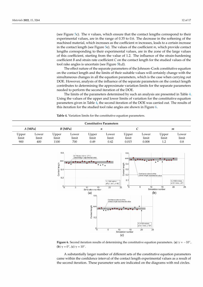
The limits of the parameters determined by such an analysis are presented in Table 4.Using the values of the upper and lower limits of variation for the constitutive equationparameters given in Table 4, the second iteration of the DOE was carried out. The results ofthis iteration for the studied tool rake angles are shown in Figure 6.
Table 4. Variation limits for the constitutive equation parameters.
Constitutive Parameters
A [MPa] B [MPa] n C m
Upperlimit
Lowerlimit
Upperlimit
Lowerlimit
Upperlimit
Lowerlimit
Upperlimit
Lowerlimit
Upperlimit
Lowerlimit
900 400 1100 700 0.49 0.42 0.015 0.008 1.2 0.8
Materials 2022, 15, x FOR PEER REVIEW 13 of 18
length contributes to determining the approximate variation limits for the separate pa-rameters needed to perform the second iteration of the DOE.
The limits of the parameters determined by such an analysis are presented in Table 4. Using the values of the upper and lower limits of variation for the constitutive equation parameters given in Table 4, the second iteration of the DOE was carried out. The results of this iteration for the studied tool rake angles are shown in Figure 6.
Table 4. Variation limits for the constitutive equation parameters.
Constitutive Parameters A [MPa] B [MPa] n C m
Upper limit
Lower limit
Upper limit
Lower limit
Upper limit
Lower limit
Upper limit
Lower limit
Upper limit
Lower limit
900 400 1100 700 0.49 0.42 0.015 0.008 1.2 0.8
A substantially larger number of different sets of the constitutive equation parame-ters came within the confidence interval of the contact length experimental values as a result of the second iteration. These parameter sets are indicated on the diagrams with red circles.
(a) (b)
(c)
Figure 6. Second iteration results of determining the constitutive equation parameters. (a) γ = −10°, (b) γ = 0°, (c) γ = 10°.
Thus, for each value of the tool rake angle considered in this study, there is some set of constitutive equation parameters that provides a numerically simulated contact length approximately corresponding to its experimental value. The generalized values of the constitutive equation parameters satisfying all the studied values of the tool rake angles may be determined by finding the intersection of the pluralities of the parameters defined as a result of the second iteration (see Figure 6). Naturally, these generalized values can be defined only if the plurality intersection is not empty. In the case of an empty plurality, the algorithm for determining the generalized parameters of the constitutive equation should provide for the redefining of the parameter limits for subsequent iterations and possibly the increasing of the number of simulations. A similar methodology for finding the multiple plurality intersections of the constitutive equation parameters can also be
Figure 6. Second iteration results of determining the constitutive equation parameters. (a) γ = −10◦,(b) γ = 0◦, (c) γ = 10◦.
A substantially larger number of different sets of the constitutive equation parameterscame within the confidence interval of the contact length experimental values as a result ofthe second iteration. These parameter sets are indicated on the diagrams with red circles.

Materials 2022, 15, 3264 13 of 17
Thus, for each value of the tool rake angle considered in this study, there is some setof constitutive equation parameters that provides a numerically simulated contact lengthapproximately corresponding to its experimental value. The generalized values of theconstitutive equation parameters satisfying all the studied values of the tool rake anglesmay be determined by finding the intersection of the pluralities of the parameters definedas a result of the second iteration (see Figure 6). Naturally, these generalized values can bedefined only if the plurality intersection is not empty. In the case of an empty plurality, thealgorithm for determining the generalized parameters of the constitutive equation shouldprovide for the redefining of the parameter limits for subsequent iterations and possibly theincreasing of the number of simulations. A similar methodology for finding the multipleplurality intersections of the constitutive equation parameters can also be applied to anycutting characteristic or to a combination of several cutting characteristics obtained by theconvolution product of individual characteristics.
The software algorithm developed based on this methodology provides a finding ofthe required plurality intersection of the constitutive equation parameter set. The developedalgorithm implements redefinition and refinement of the parameter limits for successivesimulation iterations in the detection of an empty plurality intersection of parameter sets.One of the most acceptable variants of the set of the constitutive equation parameters,determined using the described algorithm, is listed in Table 5.
Table 5. Generalized values of the constitutive equation parameters.
Constitutive Parameters
A [MPa] B [MPa] n C m
720 895 0.475 0.012 0.98
Using the parameter values presented in Table 5, the contact length during cuttingwas simulated at different cutting speeds and depths of cut, as well as the tool rake angles.Exemplarily, Figure 7 presents the dependency of the contact length on these values.
The largest deviation of the simulated contact length from its experimental valueat different cutting speeds was 12% and is observed at a cutting speed of 150 m/min—Figure 7a. For the other examined values of cutting speed, the deviation of the simulatedcontact length from its experimental value does not exceed 9%. Therefore, a significantincrease in the cutting speed leads to an increase in the deviation of the simulated contactlength values from its experimental value. The further increase in the cutting speed andtransition to high-speed cutting is expected to lead to a significant deviation between thesimulated and the experimentally determined contact length values. This is most likelydue to the fact that the stress–strain state of the machined material in all the cutting zonesand, in particular, in the secondary cutting zone is predominantly influenced by the cuttingtemperature. Increasing the cutting temperature at high cutting speeds leads to higherdegrees of machined material softening and, thus, reduces the simulated contact lengthbetween the tool rake face and the chip. The difference in the simulated and experimentalvalues of the contact length at different tool rake angles is approximately the same and doesnot exceed 4%—Figure 7b. The largest difference between the simulated contact lengthand its experimental value when changing the cutting depth is 4.3% and is observed at acutting depth of 0.05 mm—Figure 7c.
Thus, the generalized set of the constitutive equation parameters, determined usingthe developed software algorithm, provides an insignificant deviation of the simulatedcontact length values from their experimental values when changing the cutting modesand tool geometry within a relatively wide range.

Materials 2022, 15, 3264 14 of 17
Materials 2022, 15, x FOR PEER REVIEW 14 of 18
applied to any cutting characteristic or to a combination of several cutting characteristics obtained by the convolution product of individual characteristics.
The software algorithm developed based on this methodology provides a finding of the required plurality intersection of the constitutive equation parameter set. The devel-oped algorithm implements redefinition and refinement of the parameter limits for suc-cessive simulation iterations in the detection of an empty plurality intersection of param-eter sets. One of the most acceptable variants of the set of the constitutive equation pa-rameters, determined using the described algorithm, is listed in Table 5.
Table 5. Generalized values of the constitutive equation parameters.
Constitutive Parameters A [MPa] B [MPa] n C m
720 895 0.475 0.012 0.98
Using the parameter values presented in Table 5, the contact length during cutting was simulated at different cutting speeds and depths of cut, as well as the tool rake angles. Exemplarily, Figure 7 presents the dependency of the contact length on these values.
The largest deviation of the simulated contact length from its experimental value at different cutting speeds was 12% and is observed at a cutting speed of 150 m/min—Figure 7a. For the other examined values of cutting speed, the deviation of the simulated contact length from its experimental value does not exceed 9%. Therefore, a significant increase in the cutting speed leads to an increase in the deviation of the simulated contact length values from its experimental value. The further increase in the cutting speed and transi-tion to high-speed cutting is expected to lead to a significant deviation between the simu-lated and the experimentally determined contact length values. This is most likely due to the fact that the stress–strain state of the machined material in all the cutting zones and, in particular, in the secondary cutting zone is predominantly influenced by the cutting temperature. Increasing the cutting temperature at high cutting speeds leads to higher degrees of machined material softening and, thus, reduces the simulated contact length between the tool rake face and the chip. The difference in the simulated and experimental values of the contact length at different tool rake angles is approximately the same and does not exceed 4%—Figure 7b. The largest difference between the simulated contact length and its experimental value when changing the cutting depth is 4.3% and is ob-served at a cutting depth of 0.05 mm—Figure 7c.
(a) (b)
Materials 2022, 15, x FOR PEER REVIEW 15 of 18
(c)
Figure 7. Dependence of simulated contact length on cutting modes and tool rake angle. (a) γ = −10°, (b) γ = 0°, (c) γ = 10°.
Thus, the generalized set of the constitutive equation parameters, determined using the developed software algorithm, provides an insignificant deviation of the simulated contact length values from their experimental values when changing the cutting modes and tool geometry within a relatively wide range.
6. Conclusions A methodology for determining the contact length of the tool rake face with the chip,
using a numerical simulation of the orthogonal cutting process for metals that form flow chips, is proposed. This methodology is based on determining the generalized parameters of the constitutive equation as the contact length is predominantly influenced by the con-stitutive equation parameters describing the model of the material to be machined. The use of this methodology provides a determination of the contact length for a wide range of cutting modes and tool geometries, particularly the tool rake angle.
For the determination of the generalized parameters of the constitutive equation, a software-implemented algorithm has been developed. The algorithm is based on finding the plurality intersection of these parameter sets. The sets of constitutive equation param-eters are determined by DOE (design of experiments) and refined by subsequent multiple iterations.
The validity of the constitutive equation parameters was evaluated by comparing the simulated values of the contact length with its experimental values. The experimental value of the contact length with varying cutting speed, depth of cut, and tool rake angle was performed by an optical method. The contact length obtained by simulation of the cutting process, using the generalized parameters of the constitutive equation as a mate-rial model, differs from its experimental value by an amount not exceeding 12%.
The developed methodology for determining the total tool–chip contact length is lim-ited to the class of metals that provide the formation of flow chip and machining methods based on orthogonal free cutting. For the future, the plan is to extend the developed meth-odology to the processes of oblique free cutting and oblique non-free cutting.
Author Contributions: Conceptualization, M.S.; methodology, M.S.; software, M.S.; validation, M.S.; formal analysis, M.S. and K.D.; investigation, M.S., K.D., and C.M.; resources, T.S. and H.-C.M.; data curation, M.S. and K.D.; writing—original draft preparation, M.S., K.D., and C.M.; writ-ing—review and editing, M.S. and C.M.; visualization, M.S. and C.M.; supervision, H.-C.M. and T.S.; project administration, H.-C.M. and T.S.; funding acquisition, H.-C.M. and T.S. All authors have read and agreed to the published version of the manuscript.
Funding: This study was funded by the German Research Foundation (DFG) in the project HE-1656/153-1 “Development of a Concept for Determining the Mechanical Properties of the Cutting Material in Machining”.
Institutional Review Board Statement: Not applicable.
Figure 7. Dependence of simulated contact length on cutting modes and tool rake angle. (a) γ = −10◦,(b) γ = 0◦, (c) γ = 10◦.
6. Conclusions
A methodology for determining the contact length of the tool rake face with the chip,using a numerical simulation of the orthogonal cutting process for metals that form flowchips, is proposed. This methodology is based on determining the generalized parametersof the constitutive equation as the contact length is predominantly influenced by theconstitutive equation parameters describing the model of the material to be machined. Theuse of this methodology provides a determination of the contact length for a wide range ofcutting modes and tool geometries, particularly the tool rake angle.
For the determination of the generalized parameters of the constitutive equation, asoftware-implemented algorithm has been developed. The algorithm is based on find-ing the plurality intersection of these parameter sets. The sets of constitutive equationparameters are determined by DOE (design of experiments) and refined by subsequentmultiple iterations.
The validity of the constitutive equation parameters was evaluated by comparingthe simulated values of the contact length with its experimental values. The experimentalvalue of the contact length with varying cutting speed, depth of cut, and tool rake anglewas performed by an optical method. The contact length obtained by simulation of thecutting process, using the generalized parameters of the constitutive equation as a materialmodel, differs from its experimental value by an amount not exceeding 12%.
The developed methodology for determining the total tool–chip contact length islimited to the class of metals that provide the formation of flow chip and machining methodsbased on orthogonal free cutting. For the future, the plan is to extend the developedmethodology to the processes of oblique free cutting and oblique non-free cutting.

Materials 2022, 15, 3264 15 of 17
Author Contributions: Conceptualization, M.S.; methodology, M.S.; software, M.S.; validation, M.S.;formal analysis, M.S. and K.D.; investigation, M.S., K.D. and C.M.; resources, T.S. and H.-C.M.; datacuration, M.S. and K.D.; writing—original draft preparation, M.S., K.D. and C.M.; writing—reviewand editing, M.S. and C.M.; visualization, M.S. and C.M.; supervision, H.-C.M. and T.S.; projectadministration, H.-C.M. and T.S.; funding acquisition, H.-C.M. and T.S. All authors have read andagreed to the published version of the manuscript.
Funding: This study was funded by the German Research Foundation (DFG) in the project HE-1656/153-1 “Development of a Concept for Determining the Mechanical Properties of the CuttingMaterial in Machining”.
Institutional Review Board Statement: Not applicable.
Informed Consent Statement: Not applicable.
Data Availability Statement: Not applicable.
Acknowledgments: The authors would like to thank the German Research Foundation (DFG) fortheir support, which is highly appreciated.
Conflicts of Interest: The authors declare no conflict of interest.
References1. Oxley, P.L.B. Mechanics of Machining: An Analytical Approach to Assessing Machinability; Ellis Horwood: Chichester, UK, 1989; 242p.
[CrossRef]2. Chiffre, L.D. Mechanics of Metal Cutting and Cutting Fluid Action. Int. J. Mach. Tool Des. Res. 1977, 17, 225–234. [CrossRef]3. Kushner, V.; Storchak, M. Modelling the material resistance to cutting. Int. J. Mech. Sci. 2017, 126, 44–54. [CrossRef]4. Zorev, N.N. Interrelationship Between Shear Processes Occurring Along Tool Face and on Shear Plane in Metal Cutting. In
Proceedings of the International Production Engineering Research Conference, Pittsburgh, PA, USA, 9–12 September 1963;pp. 42–49.
5. Tsekhanov, J.; Storchak, M. Development of analytical model for orthogonal cutting. Prod. Eng. Res. Dev. 2015, 9, 247–255.[CrossRef]
6. Sadik, M.I.; Lindström, B. The role of tool-chip contact length in metal cutting. J. Mater. Process. Technol. 1993, 37, 613–627.[CrossRef]
7. Storchak, M.; Kushner, V.; Möhring, H.-C.; Stehle, T. Refinement of temperature determination in cutting zones. J. Mech. Sci.Technol. 2021, 35, 3659–3673. [CrossRef]
8. Gad, G.S.; Armarego, E.J.A.; Smithj, A.J.R. Tool-chip contact length in orthogonal machining and its importance in tool temperaturepredictions. Int. J. Prod. Res. 1992, 30, 485–501. [CrossRef]
9. Heisel, U.; Storchak, M.; Krivoruchko, D. Thermal effects in orthogonal cutting. Prod. Eng. 2013, 7, 203–211. [CrossRef]10. Balaji, A.K.; Sreeram, G.; Jawahir, I.S.; Lenz, E. The Effects of Cutting Tool Thermal Conductivity on Tool-Chip Contact Length
and Cyclic Chip Formation in Machining with Grooved Tools. CIRP Ann. 1999, 48, 33–38. [CrossRef]11. Childs, T.H.C. Friction modelling in metal cutting. Wear 2006, 260, 310–318. [CrossRef]12. Özel, T.; Altan, T. Determination of workpiece flow stress and friction at the chip–tool contact for high-speed cutting. Int. J. Mach.
Tools Manuf. 2000, 40, 133–152. [CrossRef]13. Puls, H.; Klocke, F.; Lung, D. Experimental investigation on friction under metal cutting conditions. Wear 2014, 310, 63–71.
[CrossRef]14. Özel, T. The influence of friction models on finite element simulations of machining. Int. J. Mach. Tools Manuf. 2006, 46, 518–530.
[CrossRef]15. Lee, E.H.; Shaffer, B.W. The Theory of Plasticity Applied to a Problem of Machining. J. Appl. Mech. 1951, 18, 405–413. [CrossRef]16. Abuladze, N.G. Character and the length of tool–chip contact. In Proceedings of the Machinability of Heat-Resistant and Titanium
Alloys, Mashinostroenie, Kuibyshev, Russia, 1962; pp. 68–78. (In Russian).17. Bhattacharyya, A. On the friction forces in metal cutting. In Proceedings of the 6th International Machine Tool Design and
Research Conference, Manchester, UK, 17–18 September 1963; pp. 491–505.18. Wallace, P.W.; Boothroyd, G. Tool Forces and Tool-Chip Friction in Orthogonal Machining. J. Mech. Eng. Sci. 1964, 6, 74–87.
[CrossRef]19. Poletika, M.F. Contact Loads on Tool Faces; Mashinostroenie: Moscow, Russia, 1969. (In Russian)20. Friedman, M.; Lenz, E. Investigation of the tool-chip contact length in metal cutting. Int. J. Mach. Tool Des. Res. 1970, 10, 401–416.
[CrossRef]21. Kato, S.; Yamaguchi, K.; Yamada, M. Stress Distribution at the Interface Between Tool and Chip in Machining. J. Eng. Ind. 1972,
94, 683–689. [CrossRef]22. Hastings, W.F.; Mathew, P.; Oxley, P.L.B. A machining theory for predicting chip geometry, cutting forces etc. from work material
properties and cutting conditions. Proc. R. Soc. London Ser. A 1980, 371, 569–587. [CrossRef]

Materials 2022, 15, 3264 16 of 17
23. Grzesik, W.; Nieslony, P. A computational approach to evaluate temperature and heat partition in machining with multilayercoated tools. Int. J. Mach. Tools Manuf. 2003, 43, 1311–1317. [CrossRef]
24. Sutter, G. Chip geometries during high-speed machining for orthogonal cutting conditions. Int. J. Mach. Tools Manuf. 2005, 45,719–726. [CrossRef]
25. Abukhshim, N.A.; Mativenga, P.T.; Sheikh, M.A. An investigation of the tool-chip contact length and wear in high-speed turningof EN19 steel. Proc. Inst. Mech. Eng. Part B J. Eng. Manuf. 2004, 218, 889–903. [CrossRef]
26. Iqbal, S.A.; Mativenga, P.T.; Sheikh, M.A. Characterization of machining of AISI 1045 steel over a wide range of cutting speeds.Part 1: Investigation of contact phenomena. Proc. Inst. Mech. Eng. Part B J. Eng. Manuf. 2007, 221, 909–916. [CrossRef]
27. Heisel, U.; Kushner, V.; Storchak, M. Effect of machining conditions on specific tangential forces. Prod. Eng. Res. Dev. 2012, 6,621–629. [CrossRef]
28. Iqbal, S.A.; Mativenga, P.T.; Sheikh, M.A. A comparative study of the tool–chip contact length in turning of two engineeringalloys for a wide range of cutting speeds. Int. J. Adv. Manuf. Technol. 2009, 42, 30–40. [CrossRef]
29. Ojolo, S.J.; Awe, O. Investigation into the effect of tool-chip contact length on cutting stability. J. Emerg. Trends Eng. Appl. Sci.2011, 2, 626–630.
30. Amini, S.; Kazemiyoun, M. Effect of Ultrasonic Vibrations on Chip–Tool Contact Zone in Turning of AISI304. Mater. Manuf.Process. 2014, 29, 627–633. [CrossRef]
31. Sadik, M.I.; Lindström, B. The effect of restricted contact length on tool performance. J. Mater. Process. Technol. 1995, 48, 275–282.[CrossRef]
32. Ortiz-De-Zarate, G.; Madariaga, A.; Arrazola, P.J.; Childs, T.H. A novel methodology to characterize tool-chip contact in metalcutting using partially restricted contact length tools. CIRP Ann. 2021, 70, 61–64. [CrossRef]
33. Zorev, N.N. Metal Cutting Mechanics; Pergamon Press GmbH: Frankfurt, Germany, 1966; 526p, ISBN 978-0080107233.34. Fatima, A.; Mativenga, P.T. A review of tool–chip contact length models in machining and future direction for improvement. Proc.
Inst. Mech. Eng. Part B J. Eng. Manuf. 2013, 227, 345–356. [CrossRef]35. Oxley, P.L.B. An analysis for orthogonal cutting with restricted tool-chip contact. Int. J. Mech. Sci. 1962, 4, 129–135. [CrossRef]36. De Chiffre, L.; Wanheim, T. What Can We Do About Chip Formation Mechanics? CIRP Ann. 1985, 34, 129–132. [CrossRef]37. Poletika, M.F.; Pushnykh, V.A. Contact Processes in Cutting with Cemented Carbide Tools. Key Eng. Mater. 1997, 138–140, 357–394.
[CrossRef]38. Fang, N.; Jawahir, I.S. Analytical Prediction of the Chip Back-Flow Angle in Machining With Restricted Contact Grooved Tools. J.
Manuf. Sci. Eng. 2003, 125, 210–219. [CrossRef]39. Toropov, A.; Ko, S.-L. Prediction of tool-chip contact length using a new slip-line solution for orthogonal cutting. Int. J. Mach.
Tools Manuf. 2003, 43, 1209–1215. [CrossRef]40. Das, N.S.; Dundur, S.T. Slipline field solutions for metal machining with adhesion friction and elastic effects at the chip-tool
contact region. Proc. Inst. Mech. Eng. Part B J. Eng. Manuf. 2005, 219, 57–72. [CrossRef]41. Das, N.; Dundur, S.T. A slipline field analysis of free-chip orthogonal machining with adhesion friction at rake face. Mach. Sci.
Technol. 2006, 10, 371–387. [CrossRef]42. Fang, N. Characteristic Variations of Chip Morphology and Cutting Forces in Face Milling with Flat-Faced and Grooved Tool
Inserts. JSME Int. J. Ser. A Solid Mech. Mater. Eng. 2003, 46, 230–236. [CrossRef]43. Aseev, A.S.; Sidorenko, L.S. Total and plastic contact length of chip with tool’s front surface. Russ. Eng. Res. 2011, 31, 903–909.
[CrossRef]44. Zadshakoyan, M.; Pourmostaghimi, V. Genetic equation for the prediction of tool–chip contact length in orthogonal cutting. Eng.
Appl. Artif. Intell. 2013, 26, 1725–1730. [CrossRef]45. Balaji, A.K.; Mohan, V.S. An ‘Effective Cutting Tool Thermal Conductivity’ Based Model for Tool–Chip Contact in Machining
with Multi-Layer Coated Cutting Tools. Mach. Sci. Technol. 2002, 6, 415–436. [CrossRef]46. Ozlu, E.; Molinari, A.; Budak, E. Two-Zone Analytical Contact Model Applied to Orthogonal Cutting. Mach. Sci. Technol. 2010, 14,
323–343. [CrossRef]47. Ren, C.; Ke, Z.; Chen, G.; Wu, J. Modeling of tool-chip contact length for orthogonal cutting of Ti-6Al-4V alloy considering
segmented chip formation. Trans. Tianjin Univ. 2016, 22, 525–535. [CrossRef]48. Arrazola, P.; Özel, T.; Umbrello, D.; Davies, M.; Jawahir, I. Recent advances in modelling of metal machining processes. CIRP Ann.
2013, 62, 695–718. [CrossRef]49. Gu, L. Theoretical prediction of tool-chip contact length in orthogonal metal machining by computer simulation. Chin. J. Mech.
Eng. 2002, 15, 233–237. [CrossRef]50. Strenkowski, J.S.; Moon, K.-J. Finite Element Prediction of Chip Geometry and Tool/Workpiece Temperature Distributions in
Orthogonal Metal Cutting. J. Eng. Ind. 1990, 112, 313–318. [CrossRef]51. Johnson, G.R.; Cook, W.H. A constitutive model and data for metals subjected to large strains, high strain and high temperatures.
In Proceedings of the 7th International Symposium on Ballistics, The Hague, The Netherlands, 19–21 April 1983; pp. 541–547.52. Bil, H.; Kılıç, S.; Tekkaya, A.E. A comparison of orthogonal cutting data from experiments with three different finite element
models. Int. J. Mach. Tools Manuf. 2004, 44, 933–944. [CrossRef]53. Iqbal, S.A.; Mativenga, P.; Sheikh, M.A. Contact length prediction: Mathematical models and effect of friction schemes on FEM
simulation for conventional to HSM of AISI 1045 steel. Int. J. Mach. Mach. Mater. 2008, 3, 18–33. [CrossRef]

Materials 2022, 15, 3264 17 of 17
54. Woon, K.-S.; Rahman, M.; Liu, K. Numerical and experimental study of contact behavior in the tool-based micromachining ofsteel. Int. J. Precis. Eng. Manuf. 2010, 11, 453–459. [CrossRef]
55. Courbon, C.; Mabrouki, T.; Rech, J.; Mazuyer, D.; D’Eramo, E. On the existence of a thermal contact resistance at the tool-chipinterface in dry cutting of AISI 1045: Formation mechanisms and influence on the cutting process. Appl. Therm. Eng. 2013, 50,1311–1325. [CrossRef]
56. Courbon, C.; Kramar, D.; Krajnik, P.; Pusavec, F.; Rech, J.; Kopac, J. Investigation of machining performance in high-pressure jetassisted turning of Inconel 718: An experimental study. Int. J. Mach. Tools Manuf. 2009, 49, 1114–1125. [CrossRef]
57. Kishawy, H.A.; Rogers, R.J.; Balihodzic, N. A numerical investigation of the chip-tool interface in orthogonal machining. Mach.Sci. Technol. 2002, 6, 397–414. [CrossRef]
58. Bahi, S.; Nouari, M.; Moufki, A.; El Mansori, M.; Molinari, A. A new friction law for sticking and sliding contacts in machining.Tribol. Int. 2011, 44, 764–771. [CrossRef]
59. Kushner, V.; Storchak, M. Determining mechanical characteristics of material resistance to deformation in machining. Prod. Eng.Res. Dev. 2014, 8, 679–688. [CrossRef]
60. Heisel, U.; Storchak, M.; Eberhard, P.; Gaugele, T. Experimental studies for verification of thermal effects in cutting. Prod. Eng.Res. Dev. 2011, 5, 507–515. [CrossRef]
61. Filatov, Y.D.; Filatov, A.Y.; Syrota, O.O.; Yashchuk, V.P.; Monteil, G.; Heisel, U.; Storchak, M. The influence of tool wear particlesscattering in the contact zone on the workpiece surface microprofile formation in polishing quartz. J. Superhard Mater. 2010, 32,415–422. [CrossRef]
62. Filatov, Y.D.; Sidorko, V.I.; Filatov, O.Y.; Yaschuk, V.P.; Heisel, U.; Storchak, M. Surface quality control in diamond abrasivefinishing. Proc. SPIE 2009, 7389, 73892O. [CrossRef]
63. Storchak, M.; Rupp, P.; Möhring, H.-C.; Stehle, T. Determination of Johnson–Cook Constitutive Parameters for Cutting Simulations.Metals 2019, 9, 473. [CrossRef]
64. Storchak, M.; Stehle, T.; Möhring, H.-C. Determination of thermal material properties for the numerical simulation of cuttingprocesses. Int. J. Adv. Manuf. Technol. 2021, 118, 1941–1956. [CrossRef]
65. Storchak, M.; Zakiev, I.; Träris, L. Mechanical properties of subsurface layers in the machining of the titanium alloy Ti10V2Fe3Al.J. Mech. Sci. Technol. 2018, 32, 315–322. [CrossRef]
66. Storchak, M.; Jiang, L.; Xu, Y.; Li, X. Finite element modeling for the cutting process of the titanium alloy Ti10V2Fe3Al. Prod. Eng.Res. Dev. 2016, 10, 509–517. [CrossRef]
67. Heisel, U.; Krivoruchko, D.V.; Zaloha, W.A.; Storchak, M.; Stehle, T. Thermomechanical exchange effects in machining. ZWF Z.Wirtsch. Fabr. 2009, 104, 263–272. [CrossRef]
68. Storchak, M.; Möhring, H.-C.; Stehle, T. Improving the friction model for the simulation of cutting processes. Tribol. Int. 2022, 167,107376. [CrossRef]
69. Kushner, V.; Storchak, M. Determination of Material Resistance Characteristics in Cutting. Procedia CIRP 2017, 58, 293–298.[CrossRef]
70. Heisel, U.; Krivoruchko, D.V.; Zaloha, W.A.; Storchak, M.; Stehle, T. Thermomechanical material models in the modeling ofcutting processes. ZWF Z. Wirtsch. Fabr. 2009, 104, 482–491. [CrossRef]