A comparison of cut path deviation with continuous and pulsed beam modes in diode laser chip-free...
10
A comparison of cut path deviation with continuous and pulsed beam modes in diode laser chip-free cutting of glass Salman Nisar, Lin Li, M A Sheikh, Andrew J Pinkerton Laser Processing Research Group, School of Mechanical, Aerospace and Civil Engineering, The University of Manchester, Manchester, M60 1QD, UK Abstract During laser cleaving of brittle materials, with the controlled fracture technique, thermal stresses are generated which induce the crack and extend it along the cutting path subsequently causing material separation. One of the problems in laser cutting of glass with this technique is the cut path deviation at the leading and the trailing edges of the glass sheet. Previous work with a continuous beam diode laser has shown the deviation to be partly due the high magnitudes of thermal stresses generated near the edges of the sheet. This paper reports on the effects of using a pulsed diode laser to cut soda lime glass. The effect of pulse parameters and cutting speed on the quality output variables such as cut deviation angle and surface finish are studied. Finite element modelling is also used to simulate the effects of the moving beam on stress generations to facilitate the understanding of the process mechanisms and the results are compared with the experimental data. This work shows how to minimise the cut path deviation at the edges by reducing thermal stresses using optimum pulsed diode laser parameters and providing additional flexibility to the process. Keywords: Laser, Glass, Cutting, Stress Introduction The use of the laser for cutting brittle materials using the controlled fracture technique was first proposed by Lumley [1]. He applied this technique in cutting of glass and alumina ceramic substrates using a CO 2 laser. In this technique, cutting is performed below the glass transition temperature, T g , which results in smooth edges and hence requires no further cleaning or grinding. Unlike conventional cutting technique, it is a clean process without chips and coolant and no external forces act upon the workpiece. Traditional methods for glass cutting use a diamond blade tools for scribing that weakens the glass surface and apply mechanical force for parting. This results in the weakening of glass edges by up to 60% due to the formation of micro-cracks and generation of residual stresses [2]. With the controlled fracture technique, the cracks are initiated due to absorbed photons heating up the material. The stresses near the laser spot are compressive due to high temperature. After the passage of the laser beam, these compressive stresses relax and induce local residual tensile stresses. If these stresses exceed the failure stress, σ f , given by the critical energy release rate (G c ) of the glass, the crack propagates. This condition is given by [3], E L G c f c 2 (1) where E is Young’s modulus and L c is the crack length. Tsai and Liou [4] divided the cutting process into three stages. In the first stage, fracture initiates due to tensile stresses. Stable crack growth is observed in the second stage, and in the third stage, the crack extends unstably due to complete domination of tensile stresses. Dekker et al. [5] proposed a method similar to the controlled fracture technique for cutting glass. A small scratch is formed at the start of the cut, which helps in initiating the crack and leads to the separation of the glass. The controlled fracture technique has been improved by introducing a water- air mixture along the cutting path to generate tensile stresses and to maintain the temperature below the glass transition temperature [2, 6]. However, coolant adds extra cost and complexity to the process. With the controlled fracture technique, it is difficult to control crack propagation inside the glass because of its fracture characteristics and stress distribution. A major problem for this process is the difficulty to generate precise thermal and stress fields. Another
-
Upload
independent -
Category
Documents
-
view
5 -
download
0
Transcript of A comparison of cut path deviation with continuous and pulsed beam modes in diode laser chip-free...

A comparison of cut path deviation with continuous and pulsed beam modes in diode laser chip-free cutting of glass
Salman Nisar, Lin Li, M A Sheikh, Andrew J Pinkerton
Laser Processing Research Group, School of Mechanical, Aerospace and Civil Engineering,
The University of Manchester, Manchester, M60 1QD, UK
Abstract
During laser cleaving of brittle materials, with the controlled fracture technique, thermal stresses are generated which induce the crack and extend it along the cutting path subsequently causing material separation. One of the problems in laser cutting of glass with this technique is the cut path deviation at the leading and the trailing edges of the glass sheet. Previous work with a continuous beam diode laser has shown the deviation to be partly due the high magnitudes of thermal stresses generated near the edges of the sheet. This paper reports on the effects of using a pulsed diode laser to cut soda lime glass. The effect of pulse parameters and cutting speed on the quality output variables such as cut deviation angle and surface finish are studied. Finite element modelling is also used to simulate the effects of the moving beam on stress generations to facilitate the understanding of the process mechanisms and the results are compared with the experimental data. This work shows how to minimise the cut path deviation at the edges by reducing thermal stresses using optimum pulsed diode laser parameters and providing additional flexibility to the process.
Keywords: Laser, Glass, Cutting, Stress
Introduction
The use of the laser for cutting brittle materials using the controlled fracture technique was first proposed by Lumley [1]. He applied this technique in cutting of glass and alumina ceramic substrates using a CO2 laser. In this technique, cutting is performed below the glass transition temperature, Tg, which results in smooth edges and hence requires no further cleaning or grinding. Unlike conventional cutting technique, it is a clean process without chips and coolant and no external forces act upon the workpiece. Traditional methods for glass cutting use a diamond blade tools for scribing that weakens the glass surface and apply mechanical force for parting. This results in the
weakening of glass edges by up to 60% due to the formation of micro-cracks and generation of residual stresses [2].
With the controlled fracture technique, the cracks are initiated due to absorbed photons heating up the material. The stresses near the laser spot are compressive due to high temperature. After the passage of the laser beam, these compressive stresses relax and induce local residual tensile stresses. If these stresses exceed the failure stress, σf , given by the critical energy release rate (Gc) of the glass, the crack propagates. This condition is given by [3],
E
LG cf
c
2 (1)
where E is Young’s modulus and Lc is the crack length.
Tsai and Liou [4] divided the cutting process into three stages. In the first stage, fracture initiates due to tensile stresses. Stable crack growth is observed in the second stage, and in the third stage, the crack extends unstably due to complete domination of tensile stresses. Dekker et al. [5] proposed a method similar to the controlled fracture technique for cutting glass. A small scratch is formed at the start of the cut, which helps in initiating the crack and leads to the separation of the glass. The controlled fracture technique has been improved by introducing a water-air mixture along the cutting path to generate tensile stresses and to maintain the temperature below the glass transition temperature [2, 6]. However, coolant adds extra cost and complexity to the process.
With the controlled fracture technique, it is difficult to control crack propagation inside the glass because of its fracture characteristics and stress distribution. A major problem for this process is the difficulty to generate precise thermal and stress fields. Another

problem is the cut deviation (out of flatness) at the leading and the trailing edges of the glass [6-8].
The cutting process, using the controlled fracture technique with a CO2 laser, is limited to a glass thickness of 2 mm. This is because the optical penetration depth of CO2 laser with a wavelength of λ = 10.6 µm is in the range of a few microns for most glass materials. Unlike a CO2 laser, diode lasers provide higher optical penetration depth; therefore homogenous heating throughout the material thickness offers the possibility of cutting thicker glass sheets [9, 10].
The fracture mechanism of the controlled fracture technique for cutting glass using a CO2 laser where the laser beam is absorbed on the surface of the glass only has been well studied [4, 6, 11, 12]. However, there has been no reported work on the mechanism of cut deviation at the leading and trailing edges of the glass cut using a pulsed diode laser. In this study, the effect of duty cycle (pulse length / period) on cut path deviation when the beam is absorbed across the full depth of the glass is investigated. The finite element method has been used to further understand and analyse the phenomenon.
Figure 1: Schematic representation of the experimental set-up
Diode Laser Cutting Experiments
Laser Cutting Process
The laser system used for the experiments was a 1.5 kW Laserline diode laser with 808 and 940 nm wavelengths operating in continuous wave (CW) or pulsed beam mode. The size of the laser beam on the glass surface was kept at 5.0×5.5 mm2. A defocused beam was used to induce and propagate the crack and avoid melting and evaporation. The experimental set up is shown in Figure 1. The output in the pulsed beam mode was approximately square wave defined by the period and pulse length as illustrated in Figure 2. The glass samples used for cutting were provided by Pilkington plc and the dimension of workpiece was 50x50x5 mm3. Two parameters were varied: cutting speed and duty cycle while all other parameters were kept constant during the experiments. A mean power of 900 W and a period of 100 ms were used. The experimental parameters used are shown in Table 1.
Figure 2: Wave definition
Pulse length
Period
Power
Time

Table 1: Experimental parameters used during the experiments
Peak
Power (W) A
Pulse length (ms)
Period (ms)
Duty Cycle B
Cutting Speed
(mm/sec)
900 CW CW 1.0 18.5
1125 80 100 0.8 18.5
1500 60 100 0.6 18.5
900 CW CW 1.0 22.5
1125 80 100 0.8 22.5
1500 60 100 0.6 22.5
A Mean power = 900 W in all cases B Duty cycle = pulse length / period
CW = continuous wave An Ocean Optics SD 2000 fibre optic spectrometer was used to measure reflectivity and absorption characteristics of the glass at 808 and 940 nm wavelengths. The reflectivity value for the thickness of glass, ranging from 2 to 8 mm, was found to be between 5% and 7% while the absorptivity for the 5 mm thick glass was 26%. To verify the modelling, a thermal imaging camera (FLIR) was used to record the temperature distribution of the glass during cutting. The temperature measurement range for the camera was 0–1500 oC. A thermocouple of type ‘K’ was also used to measure the temperature outside the scanning path. The temperature obtained at the thermocouple position was then used to calibrate the emissivity value which was done using the post-processing (ThermaCAM Researcher Professional) software of the thermal camera.
Experimental Results on Cut Path Deviation
Cut path deviation is defined as the amount by which the leading and the trailing edges of the glass deviate from the defined cut path. It has been established by the authors in an earlier work [10] that higher magnitudes of thermal stresses at the leading and trailing edges compared to the centre of the glass sheet is partly responsible for this cut deviation. An investigation of the effect of laser cutting parameters like laser power, cutting speed and glass sheet thickness on cut path deviation has also been
conducted by the authors for a continuous wave diode laser [13].
In this study, the cut deviation (measured in degrees) on the top and bottom surfaces of the leading and trailing edges for different duty cycles and cutting speeds was captured and measured using a Polyvar optical microscope and i-Solution DT measuring software. Three samples were cut and used to measure the cut path deviation for each of the parameter combinations shown in Table 1. The mean values of cut deviation and measurement error at the top and bottom surfaces of the leading and trailing edges are given in Table 2. Figures 3 to 5 show the cut path deviation at the top and bottom surfaces of the leading and the trailing edges of the glass sheets for one sample and a cutting speed of 22.5 mm/s.
Figure 3: Cut path deviation of 5 mm thick glass for a cutting speed of 22.5 mm/s and duty cycle of 0.6 at (a) top leading edge (b) bottom leading edge (c) top trailing edge and (d) bottom trailing edge
(a) (b)
(c) (d)
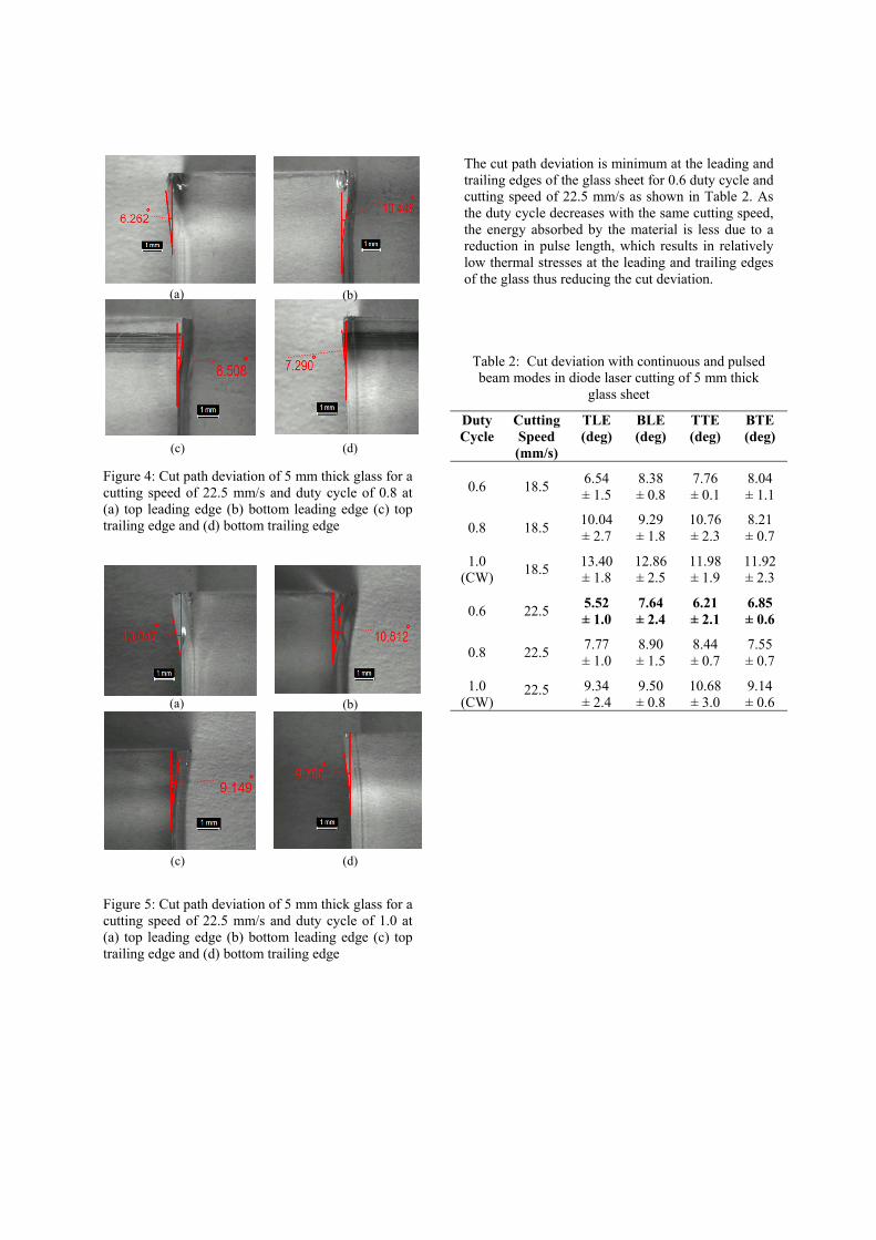
Figure 4: Cut path deviation of 5 mm thick glass for a cutting speed of 22.5 mm/s and duty cycle of 0.8 at (a) top leading edge (b) bottom leading edge (c) top trailing edge and (d) bottom trailing edge
Figure 5: Cut path deviation of 5 mm thick glass for a cutting speed of 22.5 mm/s and duty cycle of 1.0 at (a) top leading edge (b) bottom leading edge (c) top trailing edge and (d) bottom trailing edge
The cut path deviation is minimum at the leading and trailing edges of the glass sheet for 0.6 duty cycle and cutting speed of 22.5 mm/s as shown in Table 2. As the duty cycle decreases with the same cutting speed, the energy absorbed by the material is less due to a reduction in pulse length, which results in relatively low thermal stresses at the leading and trailing edges of the glass thus reducing the cut deviation.
Table 2: Cut deviation with continuous and pulsed beam modes in diode laser cutting of 5 mm thick
glass sheet
Duty Cycle
Cutting Speed (mm/s)
TLE (deg)
BLE (deg)
TTE (deg)
BTE (deg)
0.6
18.5
6.54 ± 1.5
8.38 ± 0.8
7.76 ± 0.1
8.04 ± 1.1
0.8 18.5 10.04 ± 2.7
9.29 ± 1.8
10.76 ± 2.3
8.21 ± 0.7
1.0 (CW)
18.5 13.40 ± 1.8
12.86 ± 2.5
11.98 ± 1.9
11.92 ± 2.3
0.6 22.5 5.52 ± 1.0
7.64 ± 2.4
6.21 ± 2.1
6.85 ± 0.6
0.8 22.5 7.77 ± 1.0
8.90 ± 1.5
8.44 ± 0.7
7.55 ± 0.7
1.0 (CW)
22.5 9.34 ± 2.4
9.50 ± 0.8
10.68 ± 3.0
9.14 ± 0.6
(a) (b)
(c) (d)
(a) (b)
(c) (d)
Experimental Results on Cutting Quality
The surfaces produced by laser cutting with the controlled fracture technique are smooth and with few defects except at the leading and trailing edges of the glass. A laser profile scanning system was employed to measure the average fracture surface roughness, Ra, for all the samples. To measure the surface roughness, a separation surface of 10 mm length was selected randomly and scanned.
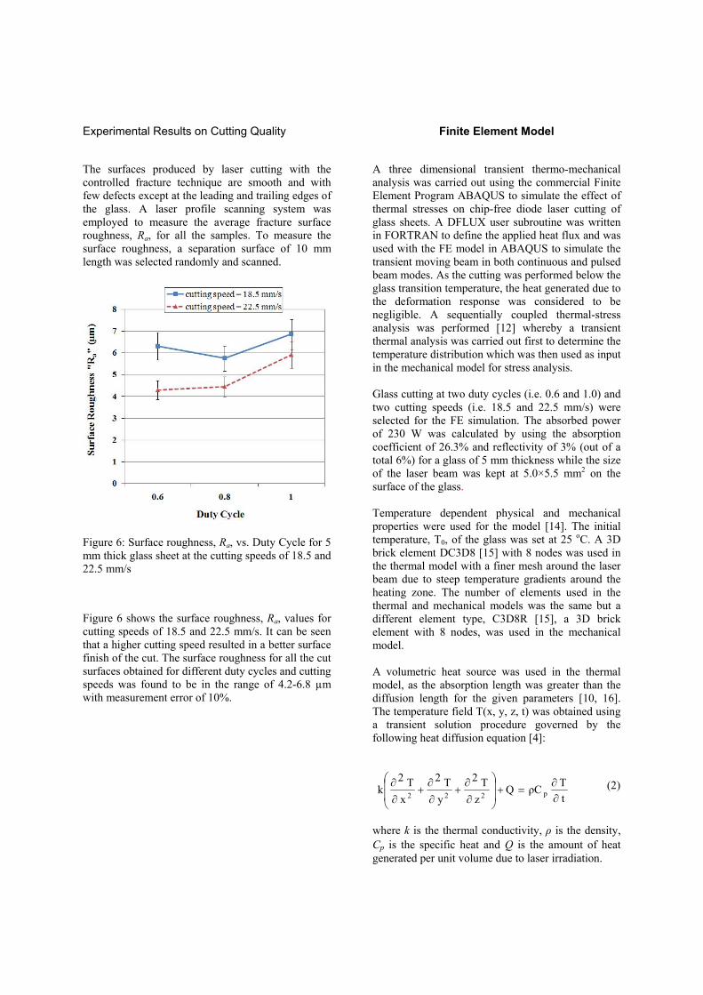
Figure 6: Surface roughness, Ra, vs. Duty Cycle for 5 mm thick glass sheet at the cutting speeds of 18.5 and 22.5 mm/s
Figure 6 shows the surface roughness, Ra, values for cutting speeds of 18.5 and 22.5 mm/s. It can be seen that a higher cutting speed resulted in a better surface finish of the cut. The surface roughness for all the cut surfaces obtained for different duty cycles and cutting speeds was found to be in the range of 4.2-6.8 µm with measurement error of 10%.
Finite Element Model
A three dimensional transient thermo-mechanical analysis was carried out using the commercial Finite Element Program ABAQUS to simulate the effect of thermal stresses on chip-free diode laser cutting of glass sheets. A DFLUX user subroutine was written in FORTRAN to define the applied heat flux and was used with the FE model in ABAQUS to simulate the transient moving beam in both continuous and pulsed beam modes. As the cutting was performed below the glass transition temperature, the heat generated due to the deformation response was considered to be negligible. A sequentially coupled thermal-stress analysis was performed [12] whereby a transient thermal analysis was carried out first to determine the temperature distribution which was then used as input in the mechanical model for stress analysis. Glass cutting at two duty cycles (i.e. 0.6 and 1.0) and two cutting speeds (i.e. 18.5 and 22.5 mm/s) were selected for the FE simulation. The absorbed power of 230 W was calculated by using the absorption coefficient of 26.3% and reflectivity of 3% (out of a total 6%) for a glass of 5 mm thickness while the size of the laser beam was kept at 5.0×5.5 mm2 on the surface of the glass. Temperature dependent physical and mechanical properties were used for the model [14]. The initial temperature, T0, of the glass was set at 25 oC. A 3D brick element DC3D8 [15] with 8 nodes was used in the thermal model with a finer mesh around the laser beam due to steep temperature gradients around the heating zone. The number of elements used in the thermal and mechanical models was the same but a different element type, C3D8R [15], a 3D brick element with 8 nodes, was used in the mechanical model. A volumetric heat source was used in the thermal model, as the absorption length was greater than the diffusion length for the given parameters [10, 16]. The temperature field T(x, y, z, t) was obtained using a transient solution procedure governed by the following heat diffusion equation [4]:
t
TρCQ
z
T2
y
T2
x
T2k p222
(2)
where k is the thermal conductivity, ρ is the density, Cp is the specific heat and Q is the amount of heat generated per unit volume due to laser irradiation.

The basic assumptions for the thermo-mechanical analysis are summarised as follows.
(i) The material (glass sheet) was homogenous and isotropic.
(ii) The laser intensity distribution was uniform.
(iii) The effect of natural convection and radiation were neglected.
(iv) The heat generation due to laser beam absorption was constant across the depth.
(v) Energy dissipation due to crack propagation in the cleaving process was neglected.
The entire length of the 50 mm track was simulated using a subroutine with continuous and pulsed beam modes for the transient analysis in all FE models. A global coordinate system was constructed as shown in Figure 7, in which x-axis represented the transverse direction, y-axis the scanning direction and z-axis the depth of the glass sheet.
The analysis was performed without a crack in the glass sheet which was clamped from one side where displacement condition 0 zyx uuu
was
prescribed, as shown in Figure 7.
Figure 7: Coordinate system and the model constraints
Results of FE Analysis
The temperature field was obtained at a point in the middle of the track defined by the coordinates x = 25, y = 25, z = 0. The maximum surface temperature results are compared with the modelling results in Table 3. It can be seen that the modelling results agree well with the experimental results with maximum difference being 11.1% which is produced by 0.6 duty cycle and 22.5 mm/s cutting speed.
Table 3: Comparison of maximum surface temperatures between the model and the experiment
It can be seen from Figures 8 and 9 that the continuous beam mode (i.e. duty cycle = 1.0) attains higher temperatures in spite of the fact that mean power is the same for all the beams modes. This is mainly due to the greater interaction time for continuous beam mode as compared to pulsed beam mode (i.e. duty cycle = 0.6). The cooling time (i.e. off time) of the pulse resulted in lower temperature distribution when compared to continuous beam mode for both cutting speeds.
Maximum Temperature (oC)
Duty Cycle Speed (mm/s)
Model Experiment
0.6 18.5 185 205 1.0 18.5 244 260 0.6 22.5 168 189 1.0 22.5 209 223
Scan speed
zy
x
)0( zyx uuu5 mm
50 mm
50 mm
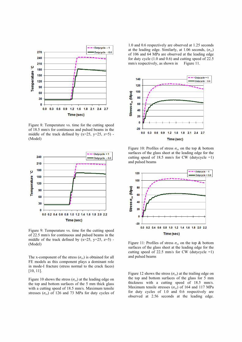
Figure 8: Temperature vs. time for the cutting speed of 18.5 mm/s for continuous and pulsed beams in the middle of the track defined by (x=25, y=25, z=5) - (Model)
Figure 9: Temperature vs. time for the cutting speed of 22.5 mm/s for continuous and pulsed beams in the middle of the track defined by (x=25, y=25, z=5) - (Model)
The x-component of the stress (σxx) is obtained for all FE models as this component plays a dominant role in mode-I fracture (stress normal to the crack faces) [10, 11].
Figure 10 shows the stress (σxx) at the leading edge on the top and bottom surfaces of the 5 mm thick glass with a cutting speed of 18.5 mm/s. Maximum tensile stresses (σxx) of 126 and 73 MPa for duty cycles of
1.0 and 0.6 respectively are observed at 1.25 seconds at the leading edge. Similarly, at 1.06 seconds, (σxx) of 106 and 64 MPa are observed at the leading edge for duty cycle (1.0 and 0.6) and cutting speed of 22.5 mm/s respectively, as shown in Figure 11.
Figure 10: Profiles of stress σxx on the top & bottom surfaces of the glass sheet at the leading edge for the cutting speed of 18.5 mm/s for CW (dutycycle =1) and pulsed beams
Figure 11: Profiles of stress σxx on the top & bottom surfaces of the glass sheet at the leading edge for the cutting speed of 22.5 mm/s for CW (dutycycle =1) and pulsed beams
Figure 12 shows the stress (σxx) at the trailing edge on the top and bottom surfaces of the glass for 5 mm thickness with a cutting speed of 18.5 mm/s. Maximum tensile stresses (σxx) of 164 and 117 MPa for duty cycles of 1.0 and 0.6 respectively are observed at 2.56 seconds at the leading edge.

Similarly, at 2.14 seconds, (σxx) of 138 and 103 MPa are observed at the trailing edge for duty cycle (1.0 and 0.6) and cutting speed of 22.5 mm/s respectively, as shown in Figure 13.
Figure 12: Profiles of stress σxx on the top & bottom surfaces of the glass sheet at the trailing edge for the cutting speed of 18.5 mm/s for CW (dutycycle =1) and pulsed beams
Figure 13: Profiles of stress σxx on the top & bottom surfaces of the glass sheet at the trailing edge for the cutting speed of 22.5 mm/s for CW (dutycycle =1) and pulsed beams
Discussion
It has been found that with an increase in cutting speed at a constant duty cycle, the cut path deviation at the leading and trailing edges decreases as shown in Table 2. This phenomenon occurs due to a reduction in interaction time between laser beam energy and workpiece which results in relatively low thermal stresses at the leading and trailing edges of the glass thus reducing the cut deviation. However, it was observed that a mean power of 900 W and cutting speed higher than 22.5 mm/s failed to cut 5 mm thick glass sheet.
It has also been identified that as the duty cycle decreases at the same cutting speed, the cut path deviation at the leading and trailing edges decreases as shown in figures 3 to 5. As duty cycle decreases, the energy absorbed by the material is less due to a reduction in pulse length, which results in relatively low thermal stresses at the leading and trailing edges of the glass thus reducing the cut deviation.
As can be seen in figures 10 to 13, the magnitudes of the tensile stresses (σxx) for 0.6 duty cycle at the leading and trailing edges are lower for 22.5 mm/s than for 18.5 mm/s cutting speed. Similarly, the magnitudes of the tensile stresses (σxx) for both the cutting speeds at the leading and trailing edges are lower for 0.6 duty cycle than duty cycle 1.0 (i.e. continuous beam mode). This is because of the smaller temperature difference achieved with pulsed beam mode; the smaller stress magnitude hence minimises the cut deviation at the leading and trailing edges of the glass sheet. The cooling time (i.e. off time) in pulse beam mode could be the reason of achieving optimum distance between the laser beam and the crack which resulted in smooth and stable initiation and propagation of the crack, hence minimising the cut deviation.
It has also been observed that by reducing the duty cycle further to a value of 0.5 with the peak power of 1500 W resulted in no cut. Because the cooling time (i.e. off time) in the pulse beam mode is reduced too much, the required energy for propagation of the crack is not achieved; therefore, it resulted in crack arrest and no cut was achieved.
From both experimental and numerical analysis, it has been found that a pulsed beam has resulted in reduced stress at the leading and trailing edges of the glass sheet that have contributed to the reduction in cut deviation compared with a CW beam.

Conclusions
The driver for this study was to analyse the behaviour of cut path deviation with a diode laser in continuous and pulsed beam mode. On the basis of the results presented, it is evident that duty cycle and cutting speed are useful parameter to manipulate temperature and stress distributions for the optimisation of laser cutting of glass. A commercial FE package ABAQUS was used to predict the stress distribution at the leading and trailing edges of the glass sheet and validate results for cut path deviation. The cut deviation at the leading and trailing edges for three duty cycles (i.e. 0.6, 0.8 and 1.0) have been quantified and shown in Figures 3, 4 and 5. The average surface roughness for all the cut surfaces obtained for different duty cycles and cutting speeds was found to be in the range of 4.2-6.8 µm with a measurement error of 10%, as shown in Figure 6. It has been found from this study that the lower magnitudes of stress (σxx) for 0.6 duty cycle results in minimum cut deviation at the leading and trailing edges for 22.5 mm/s as compared to 18.5 mm/s cutting speed. In addition, the magnitudes of tensile stresses (σxx) for 18.5 and 22.5 cutting speed at the leading and trailing edges are lower for 0.6 duty cycle as compared to duty cycle 1.0 (i.e. continuous beam mode). Therefore, it is concluded that increase in the cutting speed with constant duty cycle results in smaller cut path deviation at the leading and trailing edges of the glass sheet. It is also concluded that a decrease in the duty cycle with constant cutting speed results in smaller cut path deviation at the leading and trailing edges of the glass. However, no cut can be produced with a 0.5 duty cycle, as the energy required for the propagation of the crack was not achieved, resulting in crack arrest.
References [1] Lumley.R.R.M. Controlled Separation of
Brittle Materials Using a Laser. American Ceramic Society Bulletin. 1969;48 :850-54.
[2] A.B.Zhimalov, V.F.Solinov, V.S.Kondratenko, T.V.Kaplina. Laser Cutting of Float Glass during Production. Science for Glass Production. 2006;63 :3-5.
[3] T.L.Anderson. Fracture Mechanics: Fundamentals and Applications: Taylor & Francis Group. 2005.
[4] Chwan-Huei Tsai, Chi-Sheng Liou. Fracture Mechanism of Laser Cutting with Controlled Fracture. Journal of Manufacturing Science and Engineering, ASME. 2003;125 :519-28.
[5] J.N.Dekker, M.H.Zonneveld. Thermal Severing. The Cutting of Brittle Materials by Thermally Induced Fracture. Advances in Fracture Research Proceedings of the 7th International Conference on Fracture. 1989; 4 :2825-34.
[6] Paterson.N.N. On the Numerical Modelling of Laser Shearing of Glass Sheets used to Optimize Production Methods. Proceedings of the Institution of Mechanical Engineers Part C, Mechanical Engineering Science. 2004;218 :1-12.
[7] I.Black, M.A.Finucane. CO2 Laser Cutting of Stained Glass. International Journal of Advanced Manufacturing Technology. 1996;12 :47-59.
[8] Chwan-Huei Tsai, Bor-Chang Lin. Laser Cutting with Controlled Fracture and Pre-bending Applied to LCD Glass Separation. International Journal of Advanced Manufacturing and Technology. 2006;32 :1155-62.
[9] H.K.Tönshoff, A.Ostendorf, C.Kulik, H.Hesener, O.Haupt. Final Glass Products in

One Processing Step by the means of Laser Radiation. Proceedings of 22nd International Congress on Applications of Lasers and Electro-Optics, ICALEO: Laser Institute of America, 2003:71-80.
[10] Salman Nisar, M.A.Sheikh, Lin Li, Shakeel Safdar. Effect of Thermal Stresses on Chip-free Diode Laser Cutting of Glass. Optics and Laser Technology. 2009;41:318-27.
[11] Chwan-Huei Tsai, Bor-Chang Lin. Laser Cutting of Silica Glasses by Using the Controlled Fracture Technique. Proceedings of 23rd International Congress on Applications of Lasers and Electro-Optics, ICALEO: Laser Institute of America, 2004:34-41.
[12] Jehnming Lin, Yu-Zan Wang. Charaterisation of the Laser Cleaving on Glass Sheets with a Line-Shaped Laser Beam. Optics and Laser Technology. 2006;39:892-99.
[13] Salman Nisar, Farhan Nazir, Lin Li, M.A Sheikh. Thermal and Stress Characteristics in Diode Laser Chip-free Cutting of Glass. Proceedings of 27th International Congress on Application of Laser and Electro-Optics, ICALEO: Laser Institute of America, 2008:678-87.
[14] Hideo Awaji, Sawao Honda and Tadahiro Nishikawa. Thermal Shock Parameters of Ceramics Evaluated by Infrared Radiation Heating. International Journal of JSME. 1997;40 414-22.
[15] ABAQUS Analysis User's Manual, Volume - IV,: H.K.S Inc. 2006.
[16] A.Helebrant, C.Buerhop, R.WeiBmann. Mathematical Modelling of Temperature Distribution during CO2 Laser Irradiation of Glass. Glass Technology. 1993;34 154-8.
Meet the authors
Mr. Salman Nisar is currently studying for a PhD degree in diode laser cutting of Soda lime glass at The University of Manchester. He did his MSc in Advanced Manufacturing Technology and Systems Management at The University of Manchester before being selected for the Government of Pakistan scholarship for PhD.
Prof. Lin Li is the Head of Manufacturing and Laser Processing Research Group and Director of Laser Processing Research Centre at The University of Manchester, with author/co-author of over 450 publications, one book and inventor and co-inventor of 43 patents. Dr. M.A.Sheikh is a faculty staff member (Senior Lecturer) in the School of MACE at The University of Manchester. He received his PhD from the University of Sheffield (UK) in 1983. His work since has centered around the development of numerical techniques to model a variety of physical processes. His current work includes modeling of thermal transport and damage in composites, high speed machining, and laser processing of materials. Dr Andrew Pinkerton obtained his PhD from UMIST in 2004 after previously working as a project engineer and researching IC engine thermodynamics for UK industry. He is currently a teaching academic at The University of Manchester. His research interests include laser direct metal deposition, laser welding and analytical modelling of laser processes, with over 70 papers in these fields.