
Desktop micro-CT with a nanotube field emission x-ray source for high-resolution cardiac imaging
8
Desktop micro-CT with a nanotube field emission x-ray source for high-resolution cardiac imaging Guohua Cao a , Xiomara Calderon-Colon b , Laurel Burk a , Yueh Z. Lee a,c , Shabana Sultana b , Jianping Lu a,b , Otto Zhou a,b,d a Department of Physics and Astronomy, University of North Carolina, Chapel Hill, NC, USA 27599; b Curriculum in Applied Sciences and Engineering, University of North Carolina, Chapel Hill, NC, USA 27599; c Department of Radiology, University of North Carolina, Chapel Hill, NC, USA 27599; d Lineberger Comprehensive Cancer Center, University of North Carolina, Chapel Hill, NC, USA 27599 ABSTRACT We have previously reported the development of a dynamic micro-CT scanner with a stationary mouse bed using a compact carbon nanotube (CNT) field emission x-ray tube and preliminary results on its utility for prospectively gated cardiac imaging. In this paper we report the recent progress in improving the performance characteristics of this scanner. Through optimization of the CNT cathode, the stable emission current has been increased. The output power of the CNT x-ray source has reached ~100W peak power at 100μm focal spot size. The higher flux enables improvement of the x- ray energy spectrum to minimize the beam hardening effect and increasing the system temporal resolution by using shorter x-ray exposure time. The scanner’s temporal resolution has been increased to ~10 msec, which is sufficient for high-resolution micro-CT imaging of mouse heart and lung under free-breathing setting. The spatial resolution is maintained at 6.2 lp per mm at 10% system MTF. The nanotube micro-CT scanner’s application in mouse cardiac imaging has been demonstrated with high-resolution (80 μm and 15 msec) micro-CT of the mouse heart under free- breathing setting. Keywords: cardiac imaging, micro-CT, x-ray, carbon nanotube 1. INTRODUCTION Small animal models, particularly genetically engineered mice, are increasingly recognized as powerful discovery tools in the study of cardiovascular disease such as atherosclerosis at both macro and micro levels. Cardiac imaging of small animals is playing a critical role in phenotyping, drug discovery and basic research for heart disease 1, 2 . Among cardiac imaging modalities for small animals, micro-CT is a popular and powerful tool because of its unique contrast mechanism, high geometric accuracy and cost-effectiveness. 3, 4 Micro-CT of the beating mouse heart requires not only a high spatial resolution but also a high temporal resolution – a high spatial resolution (~100 μm) to resolve the anatomical detail of the small mouse heart (the left ventricle of an adult mouse is less than 4 mm in diameter), and a high temporal resolution (~10 ms) to minimize its rapid motion (up to 600 beats per minute). Recently cardiac micro-CT imaging of a beating mouse heart have been published in the literature 5,6,7 However, these state-of-art micro-CT systems and the associated imaging protocols are still not ideal for cardiac imaging of small animals. An ideal cardiac micro-CT system should be able to provide ~100 μm spatial resolution to detect an individual Basic Functional Unit 8 , and simultaneously provide ~10 msec temporal resolution to resolve the fast physiological dynamics 9 . Additionally, prospective gating should be used for dose efficiency. Furthermore, the mouse should be __________________________________ Further author information: G. Cao: E-mail: [email protected], O. Zhou: E-mail: [email protected] Medical Imaging 2010: Physics of Medical Imaging, edited by Ehsan Samei, Norbert J. Pelc, Proc. of SPIE Vol. 7622, 76222B · © 2010 SPIE · CCC code: 1605-7422/10/$18 · doi: 10.1117/12.844173 Proc. of SPIE Vol. 7622 76222B-1 Downloaded from SPIE Digital Library on 09 Apr 2010 to 152.2.176.242. Terms of Use: http://spiedl.org/terms
Transcript of Desktop micro-CT with a nanotube field emission x-ray source for high-resolution cardiac imaging

Desktop micro-CT with a nanotube field emission x-ray source for high-resolution cardiac imaging
Guohua Caoa, Xiomara Calderon-Colonb, Laurel Burka, Yueh Z. Leea,c, Shabana Sultanab,
Jianping Lua,b, Otto Zhoua,b,d
aDepartment of Physics and Astronomy, University of North Carolina, Chapel Hill, NC, USA 27599;
bCurriculum in Applied Sciences and Engineering, University of North Carolina, Chapel Hill, NC, USA 27599;
cDepartment of Radiology, University of North Carolina, Chapel Hill, NC, USA 27599; dLineberger Comprehensive Cancer Center, University of North Carolina, Chapel Hill, NC, USA
27599
ABSTRACT
We have previously reported the development of a dynamic micro-CT scanner with a stationary mouse bed using a compact carbon nanotube (CNT) field emission x-ray tube and preliminary results on its utility for prospectively gated cardiac imaging. In this paper we report the recent progress in improving the performance characteristics of this scanner. Through optimization of the CNT cathode, the stable emission current has been increased. The output power of the CNT x-ray source has reached ~100W peak power at 100μm focal spot size. The higher flux enables improvement of the x-ray energy spectrum to minimize the beam hardening effect and increasing the system temporal resolution by using shorter x-ray exposure time. The scanner’s temporal resolution has been increased to ~10 msec, which is sufficient for high-resolution micro-CT imaging of mouse heart and lung under free-breathing setting. The spatial resolution is maintained at 6.2 lp per mm at 10% system MTF. The nanotube micro-CT scanner’s application in mouse cardiac imaging has been demonstrated with high-resolution (80 μm and 15 msec) micro-CT of the mouse heart under free-breathing setting.
Keywords: cardiac imaging, micro-CT, x-ray, carbon nanotube
1. INTRODUCTION Small animal models, particularly genetically engineered mice, are increasingly recognized as powerful discovery tools in the study of cardiovascular disease such as atherosclerosis at both macro and micro levels. Cardiac imaging of small animals is playing a critical role in phenotyping, drug discovery and basic research for heart disease1, 2. Among cardiac imaging modalities for small animals, micro-CT is a popular and powerful tool because of its unique contrast mechanism, high geometric accuracy and cost-effectiveness.3, 4 Micro-CT of the beating mouse heart requires not only a high spatial resolution but also a high temporal resolution – a high spatial resolution (~100 μm) to resolve the anatomical detail of the small mouse heart (the left ventricle of an adult mouse is less than 4 mm in diameter), and a high temporal resolution (~10 ms) to minimize its rapid motion (up to 600 beats per minute).
Recently cardiac micro-CT imaging of a beating mouse heart have been published in the literature5,6,7 However, these state-of-art micro-CT systems and the associated imaging protocols are still not ideal for cardiac imaging of small animals. An ideal cardiac micro-CT system should be able to provide ~100 μm spatial resolution to detect an individual Basic Functional Unit8, and simultaneously provide ~10 msec temporal resolution to resolve the fast physiological dynamics9. Additionally, prospective gating should be used for dose efficiency. Furthermore, the mouse should be
__________________________________
Further author information: G. Cao: E-mail: [email protected], O. Zhou: E-mail: [email protected]
Medical Imaging 2010: Physics of Medical Imaging, edited by Ehsan Samei, Norbert J. Pelc,Proc. of SPIE Vol. 7622, 76222B · © 2010 SPIE · CCC code: 1605-7422/10/$18 · doi: 10.1117/12.844173
Proc. of SPIE Vol. 7622 76222B-1
Downloaded from SPIE Digital Library on 09 Apr 2010 to 152.2.176.242. Terms of Use: http://spiedl.org/terms
(a) (b)
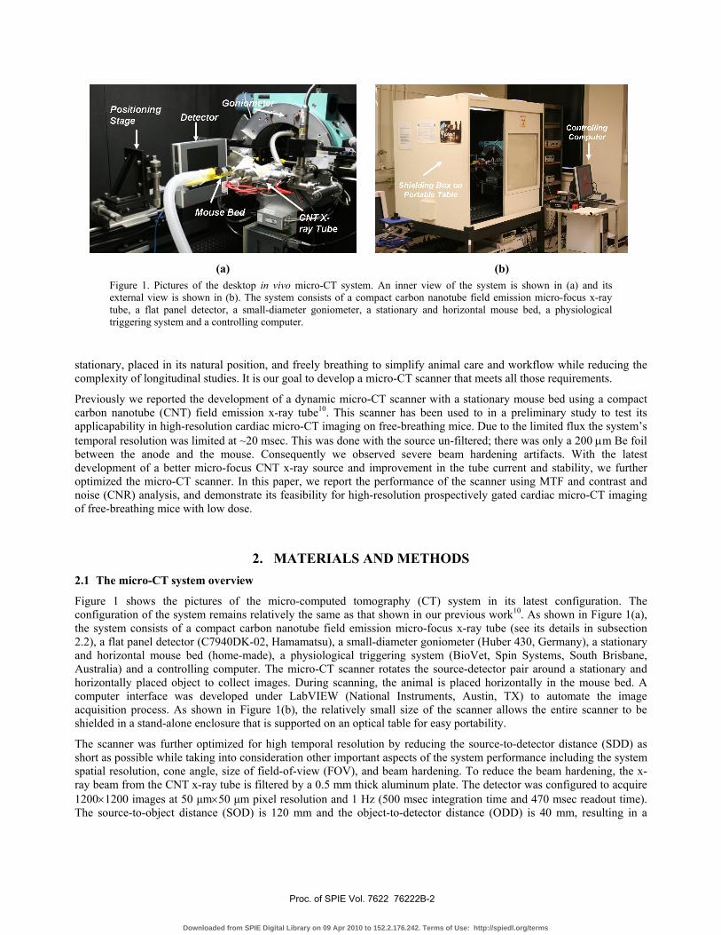
Figure 1. Pictures of the desktop in vivo micro-CT system. An inner view of the system is shown in (a) and its external view is shown in (b). The system consists of a compact carbon nanotube field emission micro-focus x-ray tube, a flat panel detector, a small-diameter goniometer, a stationary and horizontal mouse bed, a physiological triggering system and a controlling computer.
stationary, placed in its natural position, and freely breathing to simplify animal care and workflow while reducing the complexity of longitudinal studies. It is our goal to develop a micro-CT scanner that meets all those requirements.
Previously we reported the development of a dynamic micro-CT scanner with a stationary mouse bed using a compact carbon nanotube (CNT) field emission x-ray tube10. This scanner has been used to in a preliminary study to test its applicapability in high-resolution cardiac micro-CT imaging on free-breathing mice. Due to the limited flux the system’s temporal resolution was limited at ~20 msec. This was done with the source un-filtered; there was only a 200 μm Be foil between the anode and the mouse. Consequently we observed severe beam hardening artifacts. With the latest development of a better micro-focus CNT x-ray source and improvement in the tube current and stability, we further optimized the micro-CT scanner. In this paper, we report the performance of the scanner using MTF and contrast and noise (CNR) analysis, and demonstrate its feasibility for high-resolution prospectively gated cardiac micro-CT imaging of free-breathing mice with low dose.
2. MATERIALS AND METHODS 2.1 The micro-CT system overview
Figure 1 shows the pictures of the micro-computed tomography (CT) system in its latest configuration. The configuration of the system remains relatively the same as that shown in our previous work10. As shown in Figure 1(a), the system consists of a compact carbon nanotube field emission micro-focus x-ray tube (see its details in subsection 2.2), a flat panel detector (C7940DK-02, Hamamatsu), a small-diameter goniometer (Huber 430, Germany), a stationary and horizontal mouse bed (home-made), a physiological triggering system (BioVet, Spin Systems, South Brisbane, Australia) and a controlling computer. The micro-CT scanner rotates the source-detector pair around a stationary and horizontally placed object to collect images. During scanning, the animal is placed horizontally in the mouse bed. A computer interface was developed under LabVIEW (National Instruments, Austin, TX) to automate the image acquisition process. As shown in Figure 1(b), the relatively small size of the scanner allows the entire scanner to be shielded in a stand-alone enclosure that is supported on an optical table for easy portability.
The scanner was further optimized for high temporal resolution by reducing the source-to-detector distance (SDD) as short as possible while taking into consideration other important aspects of the system performance including the system spatial resolution, cone angle, size of field-of-view (FOV), and beam hardening. To reduce the beam hardening, the x-ray beam from the CNT x-ray tube is filtered by a 0.5 mm thick aluminum plate. The detector was configured to acquire 1200×1200 images at 50 μm×50 μm pixel resolution and 1 Hz (500 msec integration time and 470 msec readout time). The source-to-object distance (SOD) is 120 mm and the object-to-detector distance (ODD) is 40 mm, resulting in a
Proc. of SPIE Vol. 7622 76222B-2
Downloaded from SPIE Digital Library on 09 Apr 2010 to 152.2.176.242. Terms of Use: http://spiedl.org/terms

source-to-detector distance (SDD) of 160 mm and a geometry magnification of 1.3. This scanner geometry, along with the detector configuration, yields an effective system FOV of 46 mm×46 mm and an effective digital sampling of 38 μm×38 μm at the object plane. Projection images were reconstructed as isotropic 608 × 608 × 608 arrays with a voxel size of 76 μm using a modified Feldkamp algorithm11 using a commercial software package (Cobra EXXIM, Exxim Computing Corp., Livermore, CA).
The scanner is able to do un-gated micro-CT scans on phantoms or postmortem specimens, as well as dynamically gated micro-CT scans on living small animals. For dynamically gated cardiac micro-CT imaging, the dynamic gating method is the same as the one described previously10, 12.
2.2 The carbon nanotube field emission micro-focus x-ray tube
Figure 2 shows a picture of the carbon nanotube field emission micro-focus x-ray tube. This CNT x-ray tube has a similar design as the previous x-ray tube10, with a small change in the design for the anode. The anode material was switched to tungsten, and the size of the anode surface was reduced. The major improvement of the current x-ray tube is the performance of the CNT cathode. Through optimization of the CNT film deposition process13, the stable field emission current can be extracted from a given size CNT has been increased significantly. As a result, both the flux and lifetime of the x-ray tube are improved. The current x-ray tube can be operated reliably at 50 kVp and 2 mA anode current with 100 μm effective focal spot size.
For cardiac micro-CT, the CNT x-ray source was operated with 50 kVp anode voltage, 2 mA anode current, and 15 msec pulse width.
Figure 2. A picture of the compact carbon nanotube field emission micro-focus x-ray tube. The cone-beam angle is 30º.
2.3 System performance characterization
The performance of the micro-CT scanner was evaluated by MTF and contrast-to-noise ratio (CNR) analysis using a 10 μm tungsten wire phantom (QRM, Nuremburg, Germany) and a custom-made CNR phantom. The details about the phantoms and the analysis procedures can be found in our previous works10, 12.
2.4 Lifetime
The carbon nanotube x-ray source and the scanner have been used heavily in small animal imaging for more than 6 months without failure. During this period, we recorded the gate voltage on the carbon nanotube field emitters that was required to reach 2 mA anode current in the daily imaging experiments. The gate voltage was divided by the gap distance between the gate and the carbon nanotube cathode (190 μm in this case) to get the extraction electric field. The extraction electric field was plotted versus time to receive the lifetime plot.
Proc. of SPIE Vol. 7622 76222B-3
Downloaded from SPIE Digital Library on 09 Apr 2010 to 152.2.176.242. Terms of Use: http://spiedl.org/terms

2.5 Animal scanning
Experimental procedures carried out in this study were approved by the Institutional Animal Care and Use Committee at our institution. Several wild-type mice, weighing approximately 25 g each, were anesthetized using 1-2% isoflurane in O2 at a flow rate of 1.5–2 L min−1 from a vaporizer (Smith Medical, Waukesha, WI, USA). The anesthetized mice were positioned prone on the custom-made mouse bed. Both the electrocardiogram (ECG) and respiratory signals, as well as the derived physiological triggers, were obtained using a physiological monitoring and triggering system (BioVet, Spin Systems, South Brisbane, Australia). The respiration signal was obtained from a respiration sensor pad placed on the surface of the animal under the abdomen to monitor the maximum respiratory movement. The ECG signal was obtained from affixing three ECG electrodes to two forepaws and one hindlimb of the animal. The mice were not intubated and were allowed to breathe freely throughout the experiment. The respiration and heart rates after anesthetization were in the range of 80–120 breaths per minute and 350–450 beats per minute, respectively. Prior to imaging, a blood-pool contrast agent (Fenestra VC, 50 mg I/mL, Advanced Research Technologies, Inc., Montreal, Canada) was administered intravenously in a single bolus at a dose of 0.02 mL/g body weight as recommended by the manufacturer.
A total of 400 projections were acquired over a circular orbit of 200º with a step angle of 0.5º. The goniometer was run in step-and-shoot mode, advancing to the next view angle only if the x-ray pulse triggering condition is satisfied and the projection image is successfully acquired. The total time for the projection acquisition of one volumetric dataset was 15 – 30 min, depending on the mouse’s respiration and heart rates. The surface dose to the mouse was measured by taping gafchromic films to the mouse’s skin and irradiating the films during the scans with the same scanning parameters.
3. RESULTS 3.1 System characterization
The result from the MTF analysis is shown in Figure 3. We noticed a wire of 10 μm in diameter is sufficient to produce a significant signal, even after reconstruction was done at a voxel size of 7.6 μm. The lack of noticeable metal artifacts, which would be introduced with relatively higher x-ray absorption in the tungsten wire, leads to the accuracy of the MTF result. The 10% system MTF point was found at 6.2 lp per mm, which represents a resolution of 81 μm.
Figure 3. System MTF derived from high-resolution reconstruction of the 10 μm tungsten wire. The 10% MTF point was found at 6.2 lp per mm, which represents a resolution of 81 μm.
Proc. of SPIE Vol. 7622 76222B-4
Downloaded from SPIE Digital Library on 09 Apr 2010 to 152.2.176.242. Terms of Use: http://spiedl.org/terms

Figure 4. An axial slice image of the CNR phantom. The constituents of this tissue equivalent phantom are (1) air, (2) water, (3) fat mimic, (4) contrast agent (30 mgI mL−1) and (5) bone simulator.
Table 1. Measured CT numbers and standard deviations for the 5 materials in Figure 5.
Material CT Number Standard Deviation
Air -1000 76
Water 0 77
Fat mimic -345 76
Contrast agent 1328 89
Bone simulator 1694 319
An axial slice image of the CNR phantom is shown in Figure 4, with the constituent parts of the phantom labeled as (1) air, (2) water, (3) fat mimic, (4) contrast agent, and (5) bone simulator. The average pixel values and standard deviations in the CNR phantom image from the five material samples, in Hounsfield units, are given in Table 1. The CNR between water and air was found to be 13.1 and the CNR between water and fat mimic was found to be 4.5. The results from the MTF and CNR analyses show that the micro-CT scanner can acquire images not just at a spatial resolution as high as 6.2 lp/mm at 10% system MTF but also at an exposure as short as 10 msec without compromising the CNR.
Proc. of SPIE Vol. 7622 76222B-5
Downloaded from SPIE Digital Library on 09 Apr 2010 to 152.2.176.242. Terms of Use: http://spiedl.org/terms

10
6
Time (Day)
0 30 60 90 120 150 180 210
3.2 Lifetime
Figure 5. The extraction electric field required to reach constant 2 mA anode current during an operation period of more than 6 months for ~600 CT scans.
The extraction electric field required to reach 2 mA anode current during the 6 months operation period is plotted in Figure 5. In the 6 month period the scanner has been used to run ~600 micro-CT scans. There was a comparably larger increase in the electric field around day 120. This larger increase was caused by an arcing event within the x-ray tube that was observed during an imaging experiment. Arcing is detrimental to CNT field emitters, which causes the degradation in the performance of the CNT cathode. Overall, as we can see in Figure 6, the x-ray source has obtained a quite stable performance over 6 months. Based on its performance and our previous experiences, we estimate that the operation lifetime of this CNT x-ray tube at the present power level and workload should be more than 1 year. With improvement of the CNT cathode and the x-ray source fabrication, the lifetime of the source can be further improved.
3.3 Prospectively gated cardiac micro-CT of free-breathing mouse
Figure 6 shows example images acquired at 0 msec (diastole) after the R wave. The images presented are the 76 μm axial, coronal, and sagittal slices through the mouse heart. The major cardiovascular structures are readily identified in the images, including the aorta, left ventricle, right ventricle. The rotation of the heart has slight shifted the visualized
Figure 6. Images shown from left to right are axial, coronal, and sagittal tomographic slices from mouse cardiac micro-CT with respiratory and cardiac gating. The pixel size is 76 μm isotropically. Images were acquired at 0 msec (diastole) after the R wave.
portion of the right ventricle to a slightly different plane on the coronal images. The papillary muscles and major thoracic branches of the aorta are also readily seen.
The radiation dose for one volumetric data set was determined to be 5 cGy. All animals survived the anesthesia and imaging without difficulty.
Proc. of SPIE Vol. 7622 76222B-6
Downloaded from SPIE Digital Library on 09 Apr 2010 to 152.2.176.242. Terms of Use: http://spiedl.org/terms
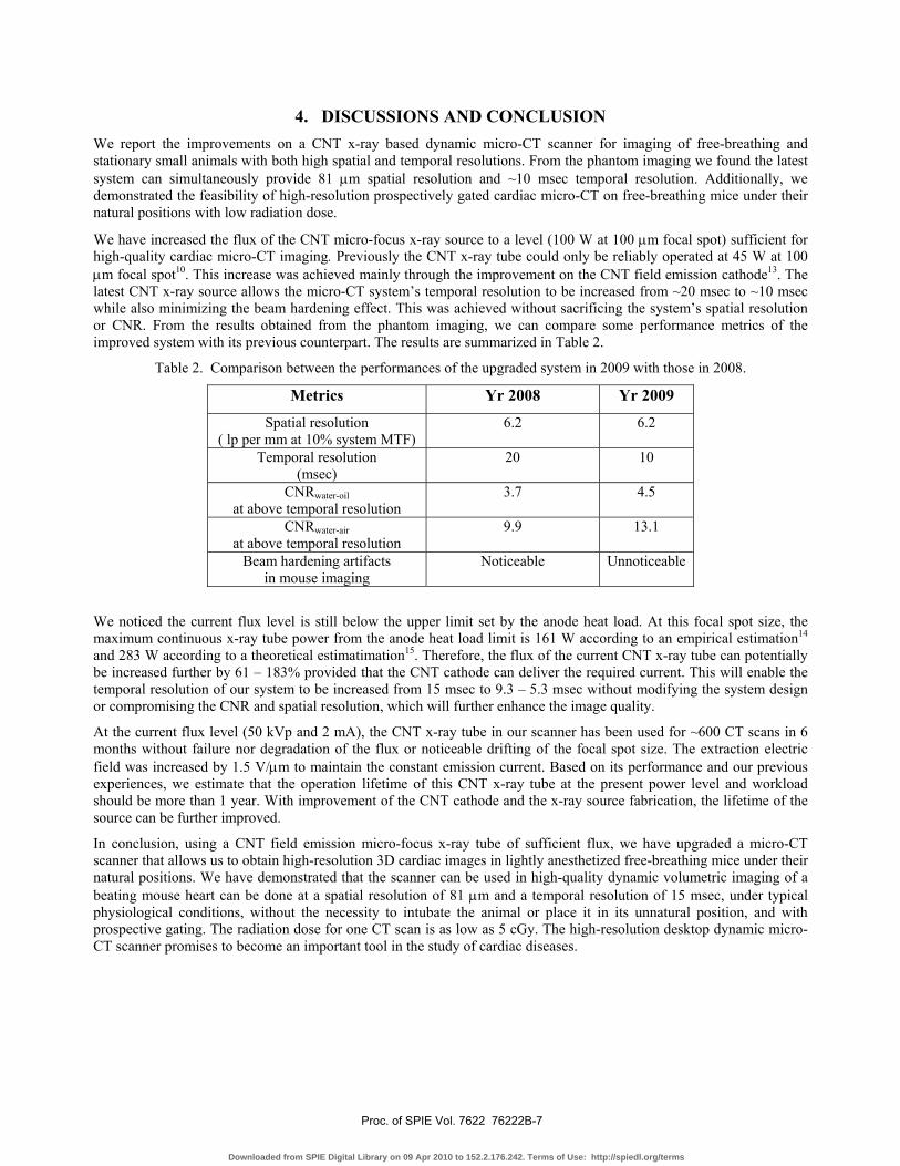
4. DISCUSSIONS AND CONCLUSION We report the improvements on a CNT x-ray based dynamic micro-CT scanner for imaging of free-breathing and stationary small animals with both high spatial and temporal resolutions. From the phantom imaging we found the latest system can simultaneously provide 81 μm spatial resolution and ~10 msec temporal resolution. Additionally, we demonstrated the feasibility of high-resolution prospectively gated cardiac micro-CT on free-breathing mice under their natural positions with low radiation dose.
We have increased the flux of the CNT micro-focus x-ray source to a level (100 W at 100 μm focal spot) sufficient for high-quality cardiac micro-CT imaging. Previously the CNT x-ray tube could only be reliably operated at 45 W at 100 μm focal spot10. This increase was achieved mainly through the improvement on the CNT field emission cathode13. The latest CNT x-ray source allows the micro-CT system’s temporal resolution to be increased from ~20 msec to ~10 msec while also minimizing the beam hardening effect. This was achieved without sacrificing the system’s spatial resolution or CNR. From the results obtained from the phantom imaging, we can compare some performance metrics of the improved system with its previous counterpart. The results are summarized in Table 2.
Table 2. Comparison between the performances of the upgraded system in 2009 with those in 2008.
Metrics Yr 2008 Yr 2009
Spatial resolution ( lp per mm at 10% system MTF)
6.2 6.2
Temporal resolution (msec)
20 10
CNRwater-oil at above temporal resolution
3.7 4.5
CNRwater-air at above temporal resolution
9.9 13.1
Beam hardening artifacts in mouse imaging
Noticeable Unnoticeable
We noticed the current flux level is still below the upper limit set by the anode heat load. At this focal spot size, the maximum continuous x-ray tube power from the anode heat load limit is 161 W according to an empirical estimation14 and 283 W according to a theoretical estimatimation15. Therefore, the flux of the current CNT x-ray tube can potentially be increased further by 61 – 183% provided that the CNT cathode can deliver the required current. This will enable the temporal resolution of our system to be increased from 15 msec to 9.3 – 5.3 msec without modifying the system design or compromising the CNR and spatial resolution, which will further enhance the image quality.
At the current flux level (50 kVp and 2 mA), the CNT x-ray tube in our scanner has been used for ~600 CT scans in 6 months without failure nor degradation of the flux or noticeable drifting of the focal spot size. The extraction electric field was increased by 1.5 V/μm to maintain the constant emission current. Based on its performance and our previous experiences, we estimate that the operation lifetime of this CNT x-ray tube at the present power level and workload should be more than 1 year. With improvement of the CNT cathode and the x-ray source fabrication, the lifetime of the source can be further improved.
In conclusion, using a CNT field emission micro-focus x-ray tube of sufficient flux, we have upgraded a micro-CT scanner that allows us to obtain high-resolution 3D cardiac images in lightly anesthetized free-breathing mice under their natural positions. We have demonstrated that the scanner can be used in high-quality dynamic volumetric imaging of a beating mouse heart can be done at a spatial resolution of 81 μm and a temporal resolution of 15 msec, under typical physiological conditions, without the necessity to intubate the animal or place it in its unnatural position, and with prospective gating. The radiation dose for one CT scan is as low as 5 cGy. The high-resolution desktop dynamic micro-CT scanner promises to become an important tool in the study of cardiac diseases.
Proc. of SPIE Vol. 7622 76222B-7
Downloaded from SPIE Digital Library on 09 Apr 2010 to 152.2.176.242. Terms of Use: http://spiedl.org/terms

ACKNOWLEDGMENTS We would like to thank Drs. E. Kang and M. Willis of the McCallister Heart Institute at UNC for providing the wild-type mouse samples, and Drs. J. Zhang and S. Chang of the Department of Radiation Oncology at UNC for helping on the dose measurement. We would also like to thank Dr. D. S. Lalush of the Department of Biomedical Engineering at NCSU, Dr. E. A. Hoffman of the Department of Radiology at University of Iowa, Drs. W. Lin, Y. Hong, and B. Yoder of the Department of Biomedical Engineering at UNC for their helpful discussions, and Drs. H. Geng and B. Gao of Xintek for assistance in carbon nanotube cathode fabrication. This work was partially supported by NIH-NCI (U54CA119343), NIH-NIBIB (4R33EB004204-01), and Xintek, Inc.
REFERENCES
1. S. Hume and R. Myers, "Dedicated small animal scanners: A new tool for drug development?," CURRENT PHARMACEUTICAL DESIGN 8, 1497-1511 (2002). 2. V. Koo, P. W. Hamilton and K. Williamson, "Non-invasive in vivo imaging in small animal research," CELLULAR ONCOLOGY 28, 127-139 (2006). 3. C. T. Badea, E. Bucholz, L. W. Hedlund, H. A. Rockman and G. A. Johnson, "Imaging Methods for Morphological and Functional Phenotyping of the Rodent Heart," Toxicologic Pathology 34, 111-117 (2006). 4. K. Johnson, "Introduction to Rodent Cardiac Imaging," ILAR J. 49, 27-34 (2008). 5. T. Sera, H. Yokota, K. Fujisaki, K. Fukasaku, H. Tachibana, K. Uesugi, N. Yagi and R. Himeno, "Development of high-resolution 4D in vivo-CT for visualization of cardiac and respiratory deformations of small animals," Phys. Med. Biol. 53, 4285-4301 (2008). 6. C. T. Badea, B. Fubara, L. W. Hedlund and G. A. Johnson, "4-D Micro-CT of the Mouse Heart," Molecular Imaging 4, 110-116 (2005). 7. M. Drangova, N. L. Ford, S. A. Detombe, A. R. Wheatley and D. W. Holdsworth, "Fast Retrospectively Gated Quantitative Four-Dimensional {(4D)} Cardiac Micro Computed Tomography Imaging of Free-Breathing Mice," Investigative Radiology 42, 85-94 (2007). 8. E. L. Ritman, "Small-animal CT: Its difference from, and impact on, clinical CT," Nuclear Instruments and Methods in Physics Research A 580, 968-970 (2007). 9. C. Badea, L. W. Hedlund and G. A. Johnson, "Micro-CT with respiratory and cardiac gating," Med. Phys. 31, 3324-3329 (2004). 10. G. Cao, X. Calderon-Colon, P. Wang, L. Burk, Y. Z. Lee, R. Rajaram, S. Sultana, D. Lalush, J. Lu and O. Zhou, "A dynamic micro-CT scanner with a stationary mouse bed using a compact carbon nanotube field emission x-ray tube," in Medical Imaging 2009: Physics of Medical Imaging, Vol. 7258, edited by S. Ehsan and H. Jiang (2009), pp. 72585Q. 11. L. A. Feldkamp, L. C. Davis and J. W. Kress, "Practical cone-beam algorithm," J. Opt. Soc. Am. A1, 612-619 (1984). 12. G. Cao, Y. Z. Lee, R. Peng, Z. Liu, R. Rajaram, X. Calderon-Colon, L. An, P. Wang, T. Phan, S. Sultana, D. S. Lalush, J. P. Lu and O. Zhou, "A dynamic micro-CT scanner based on a carbon nanotube field emission x-ray source," Phys. Med. Biol. 54, 2323-2340 (2009). 13. X. Calderon-Colon, H. Geng, B. Gao, L. An, G. Cao and O. Zhou, "A carbon nanotube field emission cathode with high current density and long-term stability," Nanotechnology 20, 325707 (325705pp) (2009). 14. M. Flynn, S. Hames, D. Reimann and S. Wilderman, "Microfocus x-ray sources for 3D microtomography," Nucl. Instrum. Methods Phys. Res. A 353, 312-315 (1994). 15. D. E. Grider, A. Wright and P. K. Ausburn, "Electron beam melting in microfocus x-ray tubes," J. Phys. D 19, 2281-2292 (1986).
Proc. of SPIE Vol. 7622 76222B-8
Downloaded from SPIE Digital Library on 09 Apr 2010 to 152.2.176.242. Terms of Use: http://spiedl.org/terms