Designing with Structural Glass - SEAW
18
8/6/2019 1 Joshua Schultz, Ph.D., P.E. 3/4/2019 Dept. of Civil & Environmental Engineering Gonzaga University Assistant Professor Designing with Structural Glass 2019 NW SEA Conference Overview • A bit about Glass • Glass design over the past century • Use of Glass in buildings today • How is Glass designed for use in buildings • Basic Method Overview • Analytical Method Overview • Analytical Method vs. Basic Method • Ongoing and Future Research A bit about Glass A brittle material, Fractures at relatively low tensile stresses, Common Glass Material Properties (Soda-Lime) • Young’s Modulus, E = 10.4 x 10 6 psi (71.7 x 10 9 Pa) • Poisson’s Ratio, = 0.22 (0.21 to 0.26) • Density, = 156 lbm/ft 3 (2500 kg/m 3 )
-
Upload
khangminh22 -
Category
Documents
-
view
0 -
download
0
Transcript of Designing with Structural Glass - SEAW
8/6/2019
1
Joshua Schultz, Ph.D., P.E.
3/4/2019
Dept. of Civil & Environmental Engineering
Gonzaga University
Assistant Professor
Designing with Structural Glass
2019 NW SEA Conference
Overview• A bit about Glass
• Glass design over the past century
• Use of Glass in buildings today
• How is Glass designed for use in buildings• Basic Method Overview• Analytical Method Overview• Analytical Method vs. Basic Method
• Ongoing and Future Research
A bit about Glass
A brittle material,
Fractures at relatively low tensile stresses,
Common Glass Material Properties (Soda-Lime)
• Young’s Modulus, E = 10.4 x 10⁶ psi (71.7 x 10⁹
Pa)
• Poisson’s Ratio, = 0.22 (0.21 to 0.26)
• Density, = 156 lbm/ft3 (2500 kg/m3)
8/6/2019
2
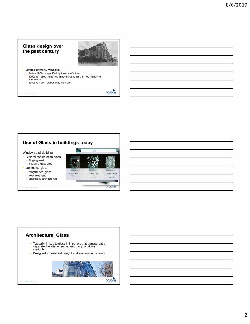
Glass design over the past century
• Limited primarily windows• Before 1950s - specified by the manufacturer• 1950s to 1980s - empirical models based on a limited number of
specimens• 1980s to now – probabilistic methods
Use of Glass in buildings today
Windows and cladding
• Glazing construction types• Single glazed• Insulating glass units
• Laminated glass
• Strengthened glass• Heat treatment• Chemically strengthened
Architectural Glass
• Typically limited to glass infill panels that transparently separate the interior and exterior, e.g. windows, skylights
• Designed to resist self weight and environmental loads
8/6/2019
3
The Farm, NetherlandsThe Shard, London The Spheres, Seattle
Structural Glass
• Includes glass components that resist the loads from other building components, e.g. beam, and/or resist occupant live loads in addition to self weight and environmental loads
YPROBABILITBREAKING ALLOWABLE MAXIMUM TONG CORESPONDI STRESS
STRESSBREAKING AVERAGE FACTOR DESIGN
• Surface flaws are primary source of failure, not necessarily point of highest stress.
• Need to use statistical modeling to obtain EFL via GFPM
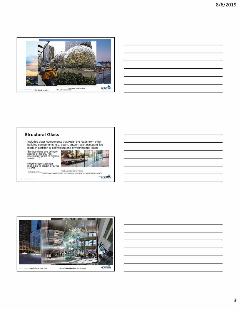
Apple Store, New York Apple Store, BostonGlass SkySlide, Los Angeles
8/6/2019
4
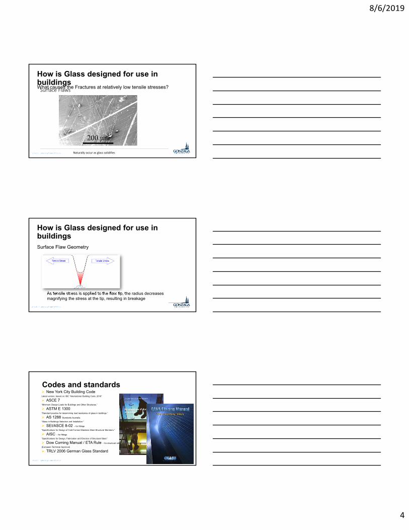
How is Glass designed for use in buildingsWhat causes the Fractures at relatively low tensile stresses?Surface Flaws
Naturally occur as glass solidifies
How is Glass designed for use in buildingsSurface Flaw Geometry
As tensile stress is applied to the flaw tip, the radius decreases magnifying the stress at the tip, resulting in breakage
Surface Flaw Tip
Codes and standards New York City Building CodeLatest version, based on: IBC “International Building Code, 2016”
ASCE 7“Minimum Design Loads for Buildings and Other Structures.”
ASTM E 1300“Standard practice for determining load resistance of glass in buildings.”
AS 1288 Standards Australia.
“Glass in Buildings Selection and Installation.”
SEI/ASCE 8-02 – for fittings
“Specifications for Design of Cold Formed Stainless Steel Structural Members.”
AISC – for fittings
“Specifications for Design, Fabrication and Erection of Structural Steel.”
Dow Corning Manual / ETA Rule – for structural silicone sealant
(European Technical Approval)
TRLV 2006 German Glass Standard

8/6/2019
5
ASTM E1300
• Standard Practice for Determining Load Resistance of Glass in Buildings• Uniform lateral load • Applies to monolithic and laminated glass constructions of rectangular
shape with continuous lateral support along one, two, three, or four edges
• Applies to insulating glass units with four-sided edge support• Does not apply to, balustrades, glass floor panels, aquariums, structural
glass members, and glass shelves• Does not apply to any form of wired, patterned, etched, sandblasted,
drilled, notched, or grooved glass with surface and edge treatments that alter the glass strength.
Original ProcedureBasic Procedure (Section 6.2)
• Determine non-factored load from charts• Monolithic glass or laminated glass (PVB)• Thickness• # of supported edges
• Factor NFL• Glass type• Load duration• IGU configuration• IGU load sharing
ASTM E1300 Glass NFL Chart
8/6/2019
6
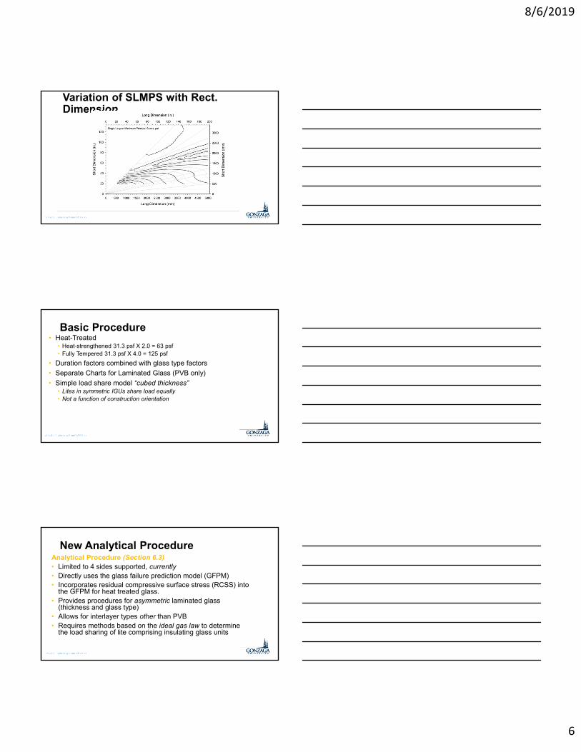
Variation of SLMPS with Rect. Dimension
Basic Procedure• Heat-Treated
• Heat-strengthened 31.3 psf X 2.0 = 63 psf• Fully Tempered 31.3 psf X 4.0 = 125 psf
• Duration factors combined with glass type factors
• Separate Charts for Laminated Glass (PVB only)
• Simple load share model “cubed thickness”• Lites in symmetric IGUs share load equally• Not a function of construction orientation
New Analytical ProcedureAnalytical Procedure (Section 6.3) • Limited to 4 sides supported, currently• Directly uses the glass failure prediction model (GFPM)• Incorporates residual compressive surface stress (RCSS) into
the GFPM for heat treated glass. • Provides procedures for asymmetric laminated glass
(thickness and glass type)• Allows for interlayer types other than PVB• Requires methods based on the ideal gas law to determine
the load sharing of lite comprising insulating glass units
8/6/2019
7
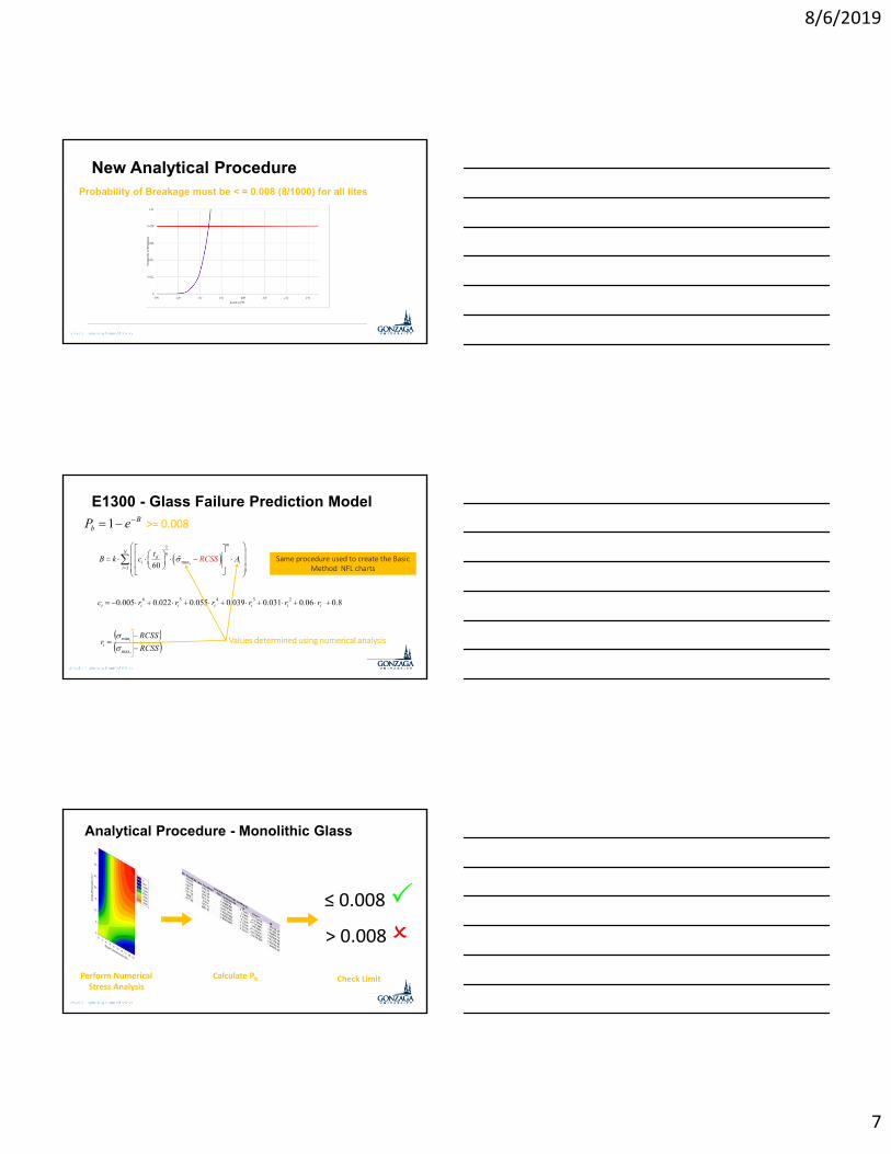
New Analytical ProcedureProbability of Breakage must be < = 0.008 (8/1000) for all lites
E1300 - Glass Failure Prediction Model
1
max1 60 i
m
N nd
i ii
RCSt
B k Sc A
RCSS
RCSSr
i
i
i
max
min
8.006.0031.0039.0055.0022.0005.0 23456 iiiiiii rrrrrrc
Values determined using numerical analysis
Same procedure used to create the Basic Method NFL charts
Bb eP 1 >= 0.008
Analytical Procedure - Monolithic Glass
Perform Numerical Stress Analysis
Calculate Pb
≤ 0.008 > 0.008
Check Limit
8/6/2019
8
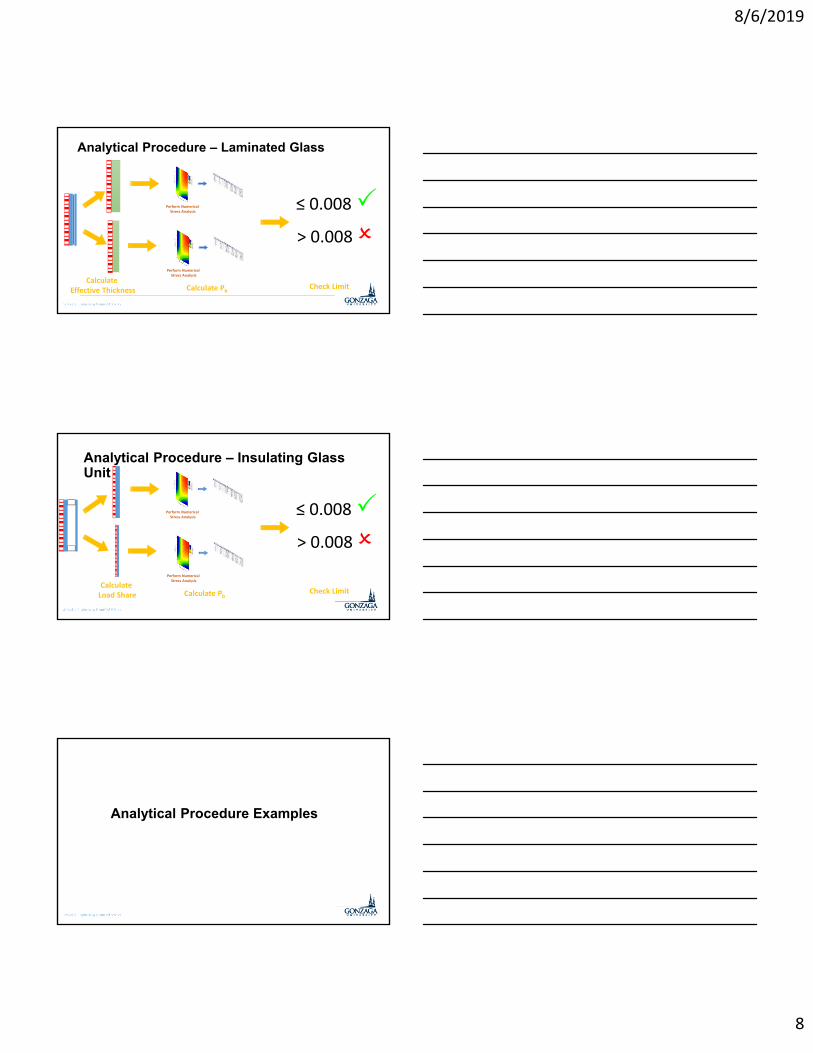
Analytical Procedure – Laminated Glass
Perform Numerical Stress Analysis
Calculate Pb
≤ 0.008 > 0.008
Check LimitCalculate
Effective Thickness
Perform Numerical Stress Analysis
Analytical Procedure – Insulating Glass Unit
Perform Numerical Stress Analysis
Calculate Pb
≤ 0.008 > 0.008
Check LimitCalculate Load Share
Perform Numerical Stress Analysis
Analytical Procedure Examples
8/6/2019
9
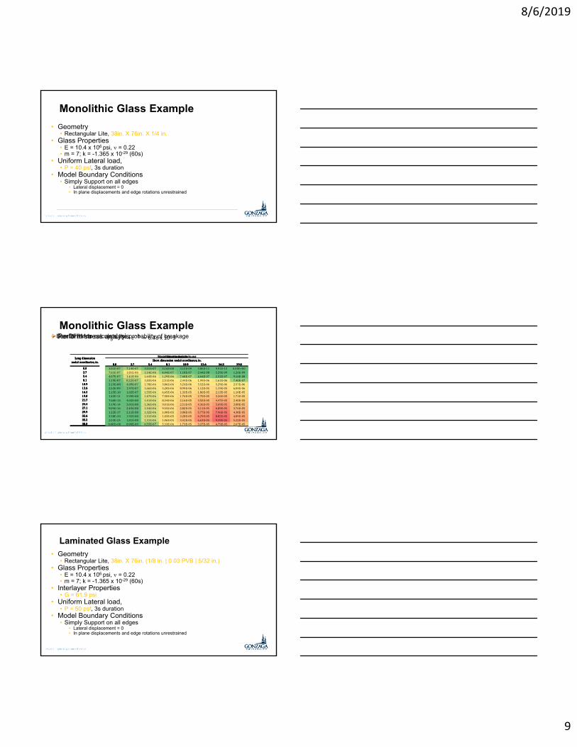
Monolithic Glass Example
• Geometry• Rectangular Lite, 38in. X 76in. X 1/4 in.
• Glass Properties• E = 10.4 x 10⁶ psi, = 0.22• m = 7; k = -1.365 x 10⁻²⁹ (60s)
• Uniform Lateral load, • P = 40 psf, 3s duration
• Model Boundary Conditions• Simply Support on all edges
• Lateral displacement = 0 • In plane displacements and edge rotations unrestrained
0.0 2.7 5.4 8.1 10.9 13.6 16.3 19.00.0 2342 2315 2045 1594 1069 570 175 02.7 2336 2383 2214 1920 1573 1241 982 8735.4 2135 2285 2301 2190 1996 1778 1592 15098.1 1795 2101 2310 2367 2301 2161 2000 1902
10.9 1405 1891 2277 2483 2525 2450 2306 213313.6 1036 1696 2236 2570 2709 2706 2624 256116.3 729 1541 2205 2642 2866 2932 2914 289319.0 494 1429 2185 2700 2991 3117 3146 314621.7 325 1351 2172 2744 3088 3260 3326 334024.4 207 1297 2164 2777 3162 3371 3465 349027.1 124 1261 2158 2801 3218 3457 3573 360629.9 67 1235 2154 2820 3261 3523 3655 369432.6 29 1219 2153 2834 3291 3569 3713 375735.3 7 1209 2152 2842 3310 3598 3749 379538.0 0 1206 2152 2845 3316 3607 3760 3808
Long dimension nodal coordinates, in.
Maximum principal stress, psiShort dimension nodal coordinates, in.
Monolithic Glass Example• Perform stress analysis
0.0 2.7 5.4 8.1 10.9 13.6 16.3 19.00.0 -2342 -2167 -1898 -1614 -1338 -1080 -853 -7382.7 -2188 -1948 -1444 -916 -470 -133 96 1895.4 -1974 -1518 -902 -284 232 611 858 9548.1 -1773 -1098 -408 240 779 1185 1468 1599
10.9 -1605 -779 -45 606 1146 1565 1878 210013.6 -1477 -576 171 812 1341 1751 2042 216916.3 -1390 -473 271 898 1412 1808 2070 216819.0 -1338 -435 300 918 1424 1808 2055 214221.7 -1309 -430 298 913 1416 1795 2035 211824.4 -1294 -437 288 905 1410 1788 2024 210527.1 -1284 -445 281 903 1411 1790 2025 210629.9 -1277 -449 279 906 1417 1798 2034 211432.6 -1271 -450 281 911 1426 1809 2045 212535.3 -1267 -449 283 916 1433 1817 2053 213338.0 -1266 -449 284 918 1436 1820 2056 2136
Long dimension nodal coordinates, in.
Minimum principal stress, psiShort dimension nodal coordinates, in.
0.0 2.7 5.4 8.1 10.9 13.6 16.3 19.00.0 0.759 0.761 0.761 0.759 0.759 0.759 0.759 0.7592.7 0.761 0.765 0.770 0.777 0.784 0.794 0.806 0.8155.4 0.761 0.770 0.780 0.793 0.808 0.827 0.853 0.8718.1 0.760 0.775 0.790 0.807 0.827 0.855 0.896 0.931
10.9 0.759 0.779 0.799 0.818 0.840 0.872 0.921 0.99213.6 0.759 0.782 0.805 0.824 0.846 0.874 0.909 0.93316.3 0.759 0.784 0.808 0.827 0.845 0.867 0.889 0.90119.0 0.759 0.784 0.809 0.827 0.843 0.860 0.875 0.88221.7 0.759 0.783 0.809 0.826 0.841 0.855 0.866 0.87124.4 0.759 0.782 0.809 0.825 0.839 0.852 0.861 0.86427.1 0.759 0.782 0.809 0.825 0.838 0.849 0.858 0.86129.9 0.759 0.781 0.809 0.825 0.838 0.848 0.856 0.85932.6 0.759 0.781 0.809 0.825 0.838 0.848 0.855 0.85835.3 0.759 0.781 0.809 0.825 0.838 0.847 0.855 0.85738.0 0.759 0.781 0.809 0.825 0.838 0.847 0.854 0.857
Long dimension nodal coordinates, in.
Biaxial Stress Correction FactorShort dimension nodal coordinates, in.
0.0 2.7 5.4 8.1 10.9 13.6 16.3 19.00.0 1.84 3.68 3.68 3.68 3.68 3.68 3.68 1.842.7 3.68 7.37 7.37 7.37 7.37 7.37 7.37 3.685.4 3.68 7.37 7.37 7.37 7.37 7.37 7.37 3.688.1 3.68 7.37 7.37 7.37 7.37 7.37 7.37 3.68
10.9 3.68 7.37 7.37 7.37 7.37 7.37 7.37 3.6813.6 3.68 7.37 7.37 7.37 7.37 7.37 7.37 3.6816.3 3.68 7.37 7.37 7.37 7.37 7.37 7.37 3.6819.0 3.68 7.37 7.37 7.37 7.37 7.37 7.37 3.6821.7 3.68 7.37 7.37 7.37 7.37 7.37 7.37 3.6824.4 3.68 7.37 7.37 7.37 7.37 7.37 7.37 3.6827.1 3.68 7.37 7.37 7.37 7.37 7.37 7.37 3.6829.9 3.68 7.37 7.37 7.37 7.37 7.37 7.37 3.6832.6 3.68 7.37 7.37 7.37 7.37 7.37 7.37 3.6835.3 3.68 7.37 7.37 7.37 7.37 7.37 7.37 3.6838.0 1.84 3.68 3.68 3.68 3.68 3.68 3.68 1.84
Long dimension nodal coordinates, in.
Tributary Area, in2
Short dimension nodal coordinates, in.0.0 2.7 5.4 8.1 10.9 13.6 16.3 19.0
0.0 3.81E-07 7.14E-07 3.01E-07 5.16E-08 3.15E-09 3.86E-11 9.91E-15 0.00E+002.7 7.61E-07 1.81E-06 1.14E-06 4.44E-07 1.18E-07 2.44E-08 5.29E-09 1.26E-095.4 4.07E-07 1.41E-06 1.63E-06 1.29E-06 7.68E-07 4.04E-07 2.31E-07 9.16E-088.1 1.19E-07 8.22E-07 1.83E-06 2.51E-06 2.44E-06 1.99E-06 1.61E-06 7.40E-07
10.9 2.13E-08 4.09E-07 1.78E-06 3.86E-06 5.24E-06 5.52E-06 5.29E-06 2.57E-0613.6 2.53E-09 1.97E-07 1.66E-06 5.20E-06 8.99E-06 1.12E-05 1.19E-05 6.04E-0616.3 2.15E-10 1.02E-07 1.55E-06 6.45E-06 1.33E-05 1.86E-05 2.13E-05 1.10E-0519.0 1.42E-11 5.99E-08 1.47E-06 7.50E-06 1.76E-05 2.70E-05 3.26E-05 1.71E-0521.7 7.60E-13 4.02E-08 1.41E-06 8.34E-06 2.16E-05 3.55E-05 4.47E-05 2.40E-0524.4 3.19E-14 3.01E-08 1.36E-06 9.01E-06 2.51E-05 4.36E-05 5.69E-05 3.08E-0527.1 9.05E-16 2.45E-08 1.34E-06 9.55E-06 2.82E-05 5.11E-05 6.89E-05 3.76E-0529.9 1.22E-17 2.11E-08 1.32E-06 1.00E-05 3.08E-05 5.77E-05 7.96E-05 4.38E-0532.6 3.58E-20 1.92E-08 1.31E-06 1.03E-05 3.28E-05 6.29E-05 8.82E-05 4.89E-0535.3 2.03E-24 1.81E-08 1.31E-06 1.06E-05 3.41E-05 6.63E-05 9.39E-05 5.22E-0538.0 0.00E+00 8.90E-09 6.55E-07 5.33E-06 1.73E-05 3.37E-05 4.79E-05 2.67E-05
Long dimension nodal coordinates, in.
Risk Function, BShort dimension nodal coordinates, in.
Use GFPM to calculate the probability of breakageSum Bi terms 𝑃 1 𝑒 6.48 x 10⁻³
Laminated Glass Example
• Geometry• Rectangular Lite, 38in. X 76in. (1/8 in. | 0.03 PVB | 5/32 in.)
• Glass Properties• E = 10.4 x 10⁶ psi, = 0.22• m = 7; k = -1.365 x 10⁻²⁹ (60s)
• Interlayer Properties• G = 61.9 psi
• Uniform Lateral load, • P = 50 psf, 3s duration
• Model Boundary Conditions• Simply Support on all edges
• Lateral displacement = 0 • In plane displacements and edge rotations unrestrained
8/6/2019
10
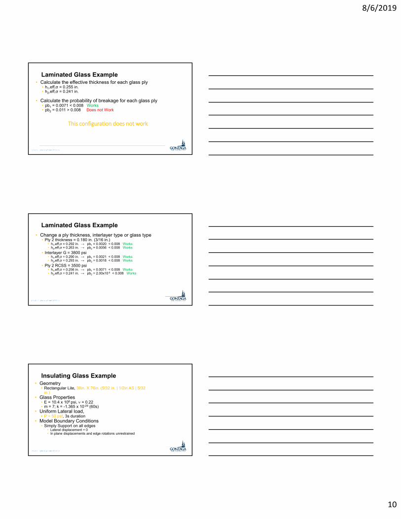
Laminated Glass Example• Calculate the effective thickness for each glass ply
• h1,eff,σ = 0.255 in.• h2,eff,σ = 0.241 in.
• Calculate the probability of breakage for each glass ply • pb1 = 0.0071 < 0.008 Works• pb2 = 0.011 > 0.008 Does not Work
This configuration does not work
Laminated Glass Example
• Change a ply thickness, interlayer type or glass type • Ply 2 thickness = 0.180 in. (3/16 in.)
• h1,eff,σ = 0.292 in. → pb1 = 0.0020 < 0.008 Works• h2,eff,σ = 0.263 in. → pb2 = 0.0056 < 0.008 Works
• Interlayer G = 3800 psi• h1,eff,σ = 0.290 in. → pb1 = 0.0021 < 0.008 Works• h2,eff,σ = 0.293 in. → pb2 = 0.0018 < 0.008 Works
• Ply 2 RCSS = 3500 psi• h1,eff,σ = 0.256 in. → pb1 = 0.0071 < 0.008 Works• h2,eff,σ = 0.241 in. → pb2 = 2.00x10⁻⁹ < 0.008 Works
Insulating Glass Example• Geometry
• Rectangular Lite, 38in. X 76in. (5/32 in. | 1/2in AS | 5/32 in.)
• Glass Properties• E = 10.4 x 10⁶ psi, = 0.22• m = 7; k = -1.365 x 10⁻²⁹ (60s)
• Uniform Lateral load, • P = 50 psf, 3s duration
• Model Boundary Conditions• Simply Support on all edges
• Lateral displacement = 0 • In plane displacements and edge rotations unrestrained
8/6/2019
11
Insulating Glass Example
• Calculate the load carried by each glass ply • L1 = 25.5 psf (50.9 %)• L2 = 24.5 psf (49.1 %)
• Calculate the probability of breakage for each glass ply • pb1 = 0.0048 < 0.008 Works• pb2 = 0.0042 < 0.008 Works
Comparison of Basic and Analytical results for select glazing constructions
Select Glazing Constructions• Monolithic
• 1/4 in. – Annealed (RCSS = 0)
• 1/4 in. – Heat-strengthened (RCSS = 3500 psi)
• 1/4 in. – Fully-Tempered (RCSS = 10000 psi)
• Laminated• 1/8 in. | 0.060 in. PVB | 1/8 in. • 5/32 in. | 0.060 in. PVB | 5/32 in. • 1/8 in. | 0.060 in. PVB | 3/16 in.
• Insulating Glass Unit• 1/8 in. | 3/8 in. | 1/8 in.
• 1/8 in. | 3/8 in. | 1/4 in.• 1/8 in. | 3/8 in. | 5/32 in. | 3/8 in. | 3/16
in.
8/6/2019
12
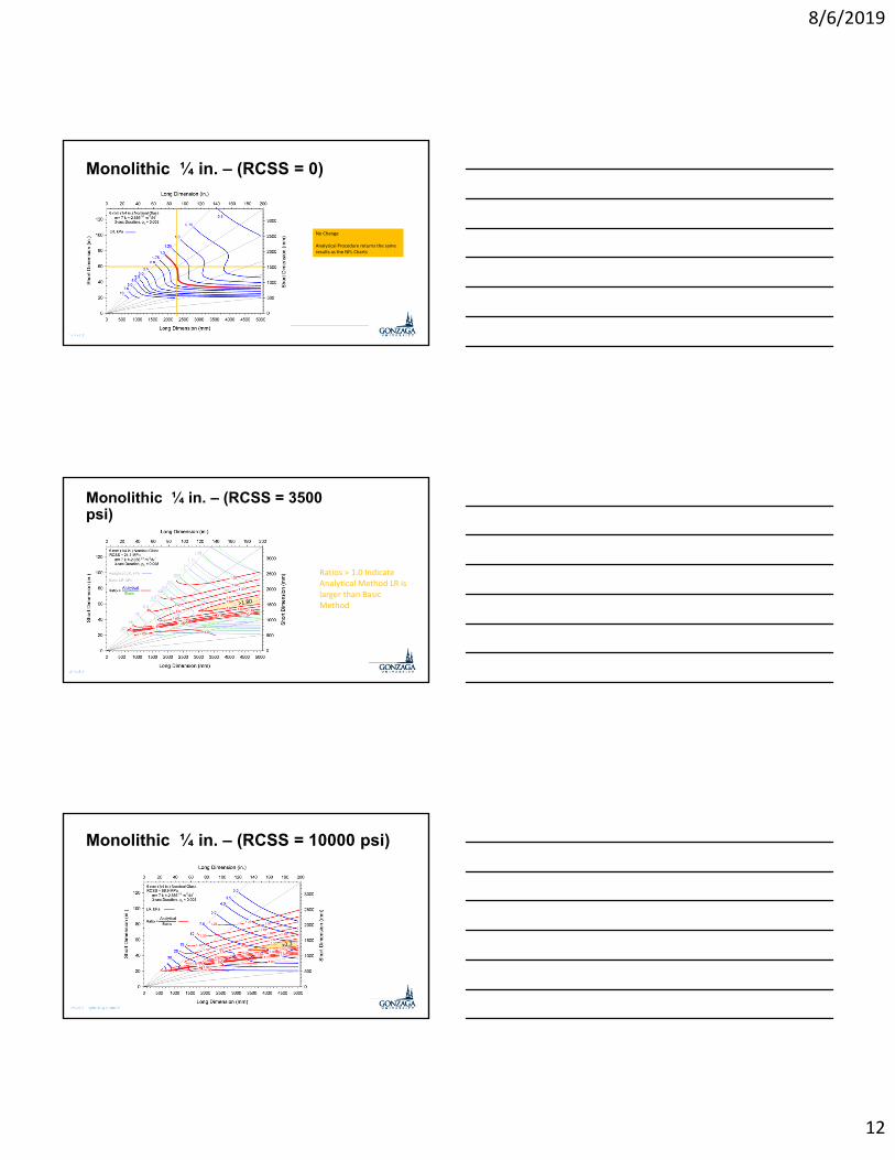
Monolithic ¼ in. – (RCSS = 0)
No Change
Analytical Procedure returns the same results as the NFL Charts
Monolithic ¼ in. – (RCSS = 3500 psi)
Ratios > 1.0 Indicate Analytical Method LR is larger than Basic Method
Monolithic ¼ in. – (RCSS = 10000 psi)

8/6/2019
13
Laminated 1/8 in. | 0.060 in. PVB | 1/8 in.
G = 61.0 psi
Laminated 5/32 in. | 0.060 in. PVB | 5/32 in.
G = 61.0 psi
Laminated 1/8 in. | 0.060 in. PVB | 3/16 in.
G = 61.0 psi
8/6/2019
14
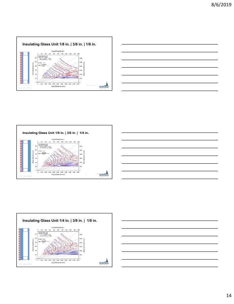
Insulating Glass Unit 1/8 in. | 3/8 in. | 1/8 in.
Insulating Glass Unit 1/8 in. | 3/8 in. | 1/4 in.
Insulating Glass Unit 1/4 in. | 3/8 in. | 1/8 in.
8/6/2019
15
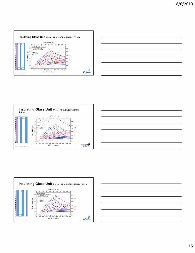
Insulating Glass Unit 1/8 in. | 3/8 in. | 5/32 in. | 3/8 in. | 3/16 in.
Insulating Glass Unit 1/8 in. | 3/8 in. | 5/32 in. | 3/8 in. | 5/16 in.
Insulating Glass Unit 3/16 in. | 3/8 in. | 5/32 in. | 3/8 in. | 1/8 in.

8/6/2019
16
Analytical Method Summary• Heat Treated Glass
• Up to 1.8 – 2.2 X larger when using the minimum RCSS• Increase varies with thickness, aspect ratio and area
• Laminated Glass• LR ratio varies with thickness, aspect ratio and area• Symmetric constructions
• Smaller LRs for smaller dimensions• LRs increase over 1.0 as area increase for ARs near 1.0
• Asymmetric constructions• LRs generally slightly larger LR
• Insulating glass• Symmetric IGUs LRs generally slightly smaller • Asymmetric IGUs LRs generally larger• Construction orientation affects load sharing
Proposed Updates to E1300
• Extended NFL Charts
• GFPM Model for Edges• Address free or partially supported edges
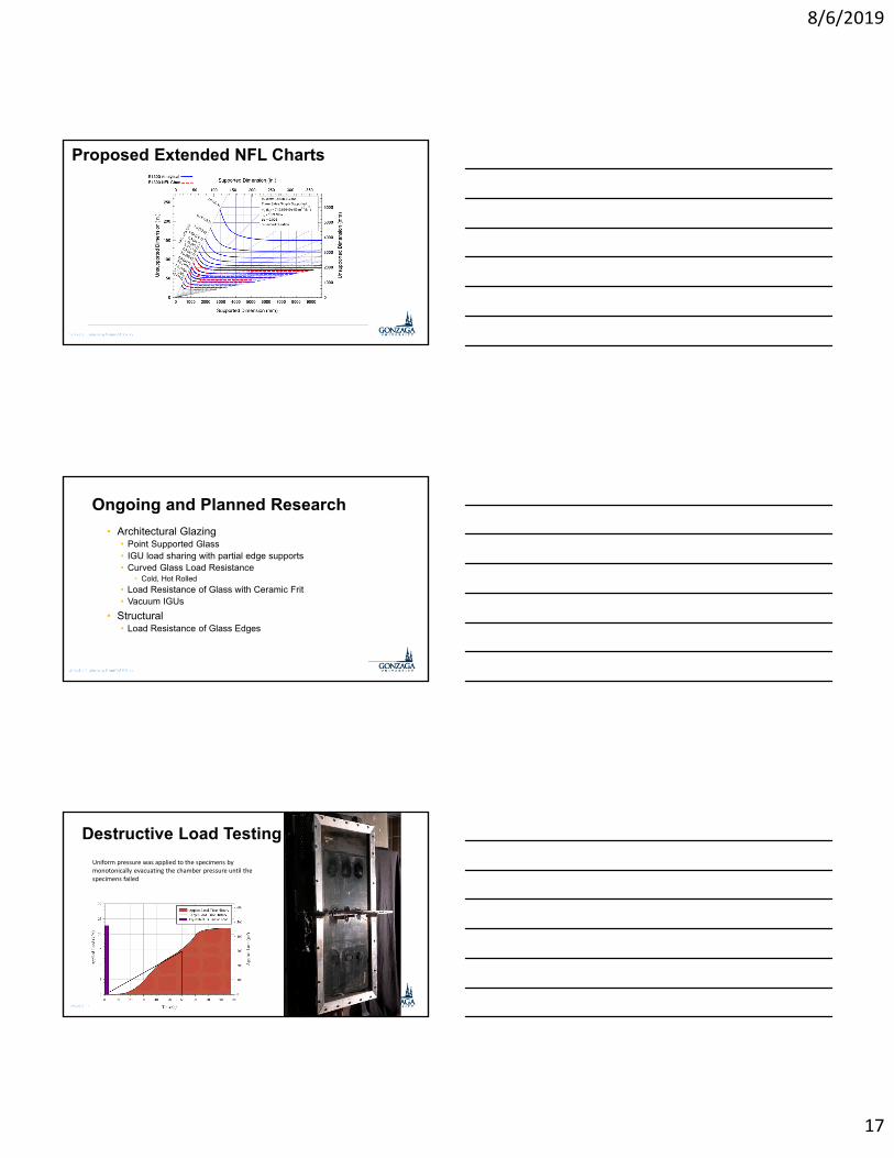
Proposed Extended NFL Charts
8/6/2019
17
Proposed Extended NFL Charts
Ongoing and Planned Research
• Architectural Glazing• Point Supported Glass• IGU load sharing with partial edge supports• Curved Glass Load Resistance
• Cold, Hot Rolled
• Load Resistance of Glass with Ceramic Frit• Vacuum IGUs
• Structural• Load Resistance of Glass Edges
Destructive Load Testing
Uniform pressure was applied to the specimens by monotonically evacuating the chamber pressure until the specimens failed
8/6/2019
18
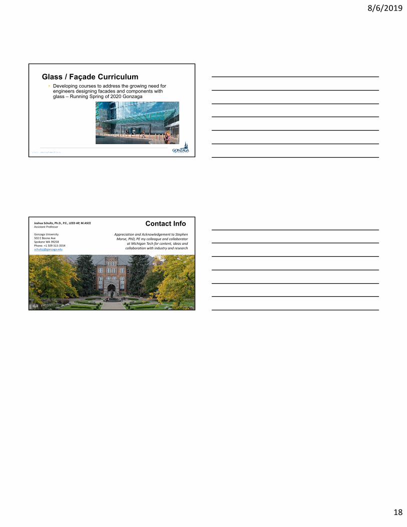
Glass / Façade Curriculum • Developing courses to address the growing need for
engineers designing facades and components with glass – Running Spring of 2020 Gonzaga
Contact InfoJoshua Schultz, Ph.D., P.E., LEED AP, M.ASCEAssistant Professor
Gonzaga University502 E Boone AveSpokane WA 99258Phone: +1 509 313‐[email protected]
Appreciation and Acknowledgement to Stephen Morse, PhD, PE my colleague and collaborator
at Michigan Tech for content, ideas and collaboration with industry and research