Introduction to structural design of glass according to current ...
24
WARSAW UNIVERSITY OF TECHNOLOGY Index 351733 FACULTY OF CIVIL ENGINEERING COMMITTEE FOR CIVIL AND WATER ENGINEERING POLISH ACADEMY OF SCIENCES ISSN 1230-2945 DOI: 10.24425/ace.2022.140634 ARCHIVES OF CIVIL ENGINEERING Vol. LXVIII ISSUE 2 2022 © 2022. Anna Jóźwik. pp. 147 –170 This is an open-access article distributed under the terms of the Creative Commons Attribution-NonCommercial-NoDerivatives License (CC BY-NC-ND 4.0, https://creativecommons.org/licenses/by-nc-nd/4.0/), which permits use, distribution, and reproduction in any medium, provided that the Article is properly cited, the use is non-commercial, and no modifications or adaptations are made. Review paper Introduction to structural design of glass according to current European standards Anna Jóźwik 1 Abstract: Glass is a material commonly used in construction. The development of technology related to it, and the increase in knowledge concerning its mechanical and strength properties offer opportunities for glass to be applied as a structural material. The advancement in glass structures, methods for their design, as well as guidelines and standards in this fields are being developed in parallel. This article describes the main assumptions contained in the German TRxV guidelines, the series of German DIN 18008 standards, and the European EN 16612, and EN 16613 standard. Moreover, the following article presents the concept of structural glass design included in the draft pre-standard prCEN/TS 19100, which provides the basis for the formulation of the European standard Eurocode 10. According to this pre-standard, structural elements of glass will be verified in four limit states, depending on the Limit State Scenario (LSS). Apart from the classic limit states, i.e., the ultimate limit state (ULS), and the serviceability limit state (SLS), it is also assumed to introduce a fracture limit state (FLS), and post- fracture limit state (PFLS). The article also addresses the issue of laminated glass working in structural elements. Depending on the coupling between the glass panes and the polymer or ionomer interlayers, laminated glass can be divided into complete coupled or uncoupled, and can work in intermediate situations. The methods for determining the effective thickness contained in European standards and guidelines are discussed in this article. Keywords: glass structures, structural glass, laminated glass, EN 16612, prCEN/TS 19100, Eu- rocode 10 1 PhD., Eng., Warsaw University of Technology, Faculty of Architecture, Koszykowa Street 55, 00-659 Warsaw, Poland, e-mail: [email protected], ORCID: 0000-0003-3252-5357
-
Upload
khangminh22 -
Category
Documents
-
view
3 -
download
0
Transcript of Introduction to structural design of glass according to current ...
WARSAW UNIVERSITY OF TECHNOLOGY Index 351733
FACULTY OF CIVIL ENGINEERINGCOMMITTEE FOR CIVIL AND WATER ENGINEERING
POLISH ACADEMY OF SCIENCES ISSN 1230-2945
DOI: 10.24425/ace.2022.140634
ARCHIVES OF CIVIL ENGINEERING
Vol. LXVIII ISSUE 2 2022© 2022. Anna Jóźwik. pp. 147 –170This is an open-access article distributed under the terms of the Creative Commons Attribution-NonCommercial-NoDerivativesLicense (CCBY-NC-ND4.0, https://creativecommons.org/licenses/by-nc-nd/4.0/),which permits use, distribution, and reproductionin any medium, provided that the Article is properly cited, the use is non-commercial, and no modifications or adaptations are made.
Review paper
Introduction to structural design of glass according tocurrent European standards
Anna Jóźwik1
Abstract:Glass is a material commonly used in construction. The development of technology related toit, and the increase in knowledge concerning its mechanical and strength properties offer opportunitiesfor glass to be applied as a structural material. The advancement in glass structures, methods for theirdesign, as well as guidelines and standards in this fields are being developed in parallel. This articledescribes the main assumptions contained in the German TRxV guidelines, the series of German DIN18008 standards, and the European EN 16612, and EN 16613 standard. Moreover, the following articlepresents the concept of structural glass design included in the draft pre-standard prCEN/TS 19100,which provides the basis for the formulation of the European standard Eurocode 10. According to thispre-standard, structural elements of glass will be verified in four limit states, depending on the LimitState Scenario (LSS). Apart from the classic limit states, i.e., the ultimate limit state (ULS), and theserviceability limit state (SLS), it is also assumed to introduce a fracture limit state (FLS), and post-fracture limit state (PFLS). The article also addresses the issue of laminated glass working in structuralelements. Depending on the coupling between the glass panes and the polymer or ionomer interlayers,laminated glass can be divided into complete coupled or uncoupled, and can work in intermediatesituations. The methods for determining the effective thickness contained in European standards andguidelines are discussed in this article.
Keywords: glass structures, structural glass, laminated glass, EN 16612, prCEN/TS 19100, Eu-rocode 10
1PhD., Eng., Warsaw University of Technology, Faculty of Architecture, Koszykowa Street 55, 00-659 Warsaw,Poland, e-mail: [email protected], ORCID: 0000-0003-3252-5357
148 A. JÓŹWIK
1. Introduction
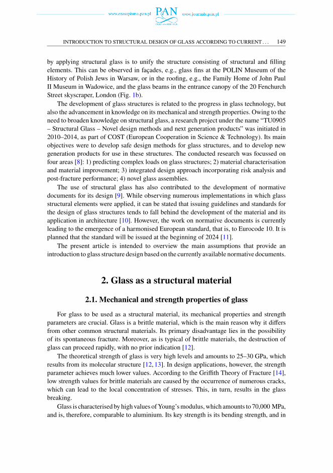
Glass provides a significant construction material in contemporary architecture. Themain advantage it offers stems from its capacity for transmitting daylight into the building.The transparency of glass inspires the search for new applications for thematerial. However,the feature also contributes to the development of new technologies. In this area, thepossibility to use glass as a structural material may be seen as one of the latest achievements.The first attempts to apply glass in self-supporting elements can be found as early as inthe 1950s, e.g., the Glasbau-Hahn exhibition hall in Frankfurt am Main [1]. However,significant development in glass structures has been observed over the last twenty-five years,as evidenced by the increasingly common buildings in which glass is used for structuralelements. One of the significant implementations from this period is the extension of theBroadfield House Glass Museum in Kingswinford [2]. The most innovative and advancedsolutions in the field of glass structures have been applied in Apple stores worldwide [3–6],such as the Apple Covent Garden store in London (Fig. 1a).
Fig. 1. Glass structures in architecture: a) glass staircases in theApple Covent Garden store in London,b) glass canopy in the 20 Fenchurch Street skyscraper in London (photos taken by the author)
It should, however, be emphasised that the scope of the use of glass as a structuralmaterial comeswith certain limitations, and only applies to selected load-bearing structures.Nonetheless, the aesthetic values presented by objects where structural glass was appliedhave prompted further projects and implementations [7]. The undoubted advantage offered
INTRODUCTION TO STRUCTURAL DESIGN OF GLASS ACCORDING TO CURRENT . . . 149
by applying structural glass is to unify the structure consisting of structural and fillingelements. This can be observed in façades, e.g., glass fins at the POLIN Museum of theHistory of Polish Jews in Warsaw, or in the roofing, e.g., the Family Home of John PaulII Museum in Wadowice, and the glass beams in the entrance canopy of the 20 FenchurchStreet skyscraper, London (Fig. 1b).The development of glass structures is related to the progress in glass technology, but
also the advancement in knowledge on its mechanical and strength properties. Owing to theneed to broaden knowledge on structural glass, a research project under the name “TU0905– Structural Glass – Novel design methods and next generation products” was initiated in2010–2014, as part of COST (European Cooperation in Science & Technology). Its mainobjectives were to develop safe design methods for glass structures, and to develop newgeneration products for use in these structures. The conducted research was focussed onfour areas [8]: 1) predicting complex loads on glass structures; 2) material characterisationand material improvement; 3) integrated design approach incorporating risk analysis andpost-fracture performance; 4) novel glass assemblies.The use of structural glass has also contributed to the development of normative
documents for its design [9]. While observing numerous implementations in which glassstructural elements were applied, it can be stated that issuing guidelines and standards forthe design of glass structures tends to fall behind the development of the material and itsapplication in architecture [10]. However, the work on normative documents is currentlyleading to the emergence of a harmonised European standard, that is, to Eurocode 10. It isplanned that the standard will be issued at the beginning of 2024 [11].The present article is intended to overview the main assumptions that provide an
introduction to glass structure design based on the currently available normative documents.
2. Glass as a structural material
2.1. Mechanical and strength properties of glass
For glass to be used as a structural material, its mechanical properties and strengthparameters are crucial. Glass is a brittle material, which is the main reason why it differsfrom other common structural materials. Its primary disadvantage lies in the possibilityof its spontaneous fracture. Moreover, as is typical of brittle materials, the destruction ofglass can proceed rapidly, with no prior indication [12].The theoretical strength of glass is very high levels and amounts to 25–30 GPa, which
results from its molecular structure [12, 13]. In design applications, however, the strengthparameter achieves much lower values. According to the Griffith Theory of Fracture [14],low strength values for brittle materials are caused by the occurrence of numerous cracks,which can lead to the local concentration of stresses. This, in turn, results in the glassbreaking.Glass is characterised by high values ofYoung’smodulus,which amounts to 70,000 MPa,
and is, therefore, comparable to aluminium. Its key strength is its bending strength, and in
150 A. JÓŹWIK
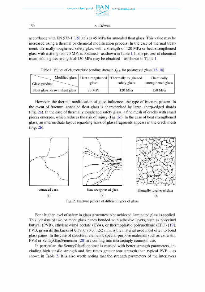
accordance with EN 572-1 [15], this is 45 MPa for annealed float glass. This value may beincreased using a thermal or chemical modification process. In the case of thermal treat-ment, thermally toughened safety glass with a strength of 120 MPa or heat-strengthenedglass with a strength of 70 MPa is obtained – as shown in Table 1. In the process of chemicaltreatment, a glass strength of 150 MPa may be obtained – as shown in Table 1.
Table 1. Values of characteristic bending strength 𝑓𝑔,𝑘 for prestressed glass [16–18]
Glass product
Modified glass Heat strengthenedglass
Thermally toughenedsafety glass
Chemicallystrengthened glass
Float glass, drawn sheet glass 70 MPa 120 MPa 150 MPa
However, the thermal modification of glass influences the type of fracture pattern. Inthe event of fracture, annealed float glass is characterised by large, sharp-edged shards(Fig. 2a). In the case of thermally toughened safety glass, a fine mesh of cracks with smallpieces emerges, which reduces the risk of injury (Fig. 2c). In the case of heat strengthenedglass, an intermediate layout regarding sizes of glass fragments appears in the crack mesh(Fig. 2b).
(a) (b) (c)
Fig. 2. Fracture pattern of different types of glass
For a higher level of safety in glass structures to be achieved, laminated glass is applied.This consists of two or more glass panes bonded with adhesive layers, such as polyvinylbutyral (PVB), ethylene-vinyl acetate (EVA), or thermoplastic polyurethane (TPU) [19].PVB, given its thickness of 0.38, 0.76 or 1.52 mm, is the material used most often to bondglass panes. In the case of structural elements, special-purpose materials such as extra stiffPVB or SentryGlas®ionomer [20] are coming into increasingly common use.In particular, the SentryGlas®ionomer is marked with better strength parameters, in-
cluding high tensile strength and five times greater tear strength than typical PVB – asshown in Table 2. It is also worth noting that the strength parameters of the interlayers
INTRODUCTION TO STRUCTURAL DESIGN OF GLASS ACCORDING TO CURRENT . . . 151
applied for laminated glass bonding, including Young’s relaxation modulus E and shearrelaxation modulus G, depend on the load duration and the ambient temperature [23–25] –as shown in Table 2.
Table 2. Physical and strength properties of the interlayer used in laminated glass [21, 22]
Properties
InterlayerPVB Extra stiff PVB
(Trosifol®)Ionomer
(SentryGlas®)
Density [kg/m3] 1065 1081 950
Coefficient of linear expansion [◦C−1] 2.2 · 10−4 1.6 · 10−4 10∼15 · 10−5(−20◦C÷32◦C)
Tensile strength [MPa] 23 32 34.5
Tear strength (tear energy) [MJ/m3] 10–15 – 50
Tensile elongation [%] > 280 > 180 400
Poisson’s ratio 0.5 0.5 0.5
Young’s relaxation modulus 𝐸 (𝑡) [MPa]30◦ for 1 hour 0.97 2.7 178
Young’s relaxation modulus 𝐸 (𝑡) [MPa]50◦ for 1 hour 0.20 1.0 12.6
Shear relaxation modulus 𝐺 (𝑡) [MPa]30◦ for 1 hour 0.33 0.92 60.0
Shear relaxation modulus 𝐺 (𝑡) [MPa]50◦ for 1 hour 0.068 0.34 4.2
2.2. Post-fracture behaviour of glass
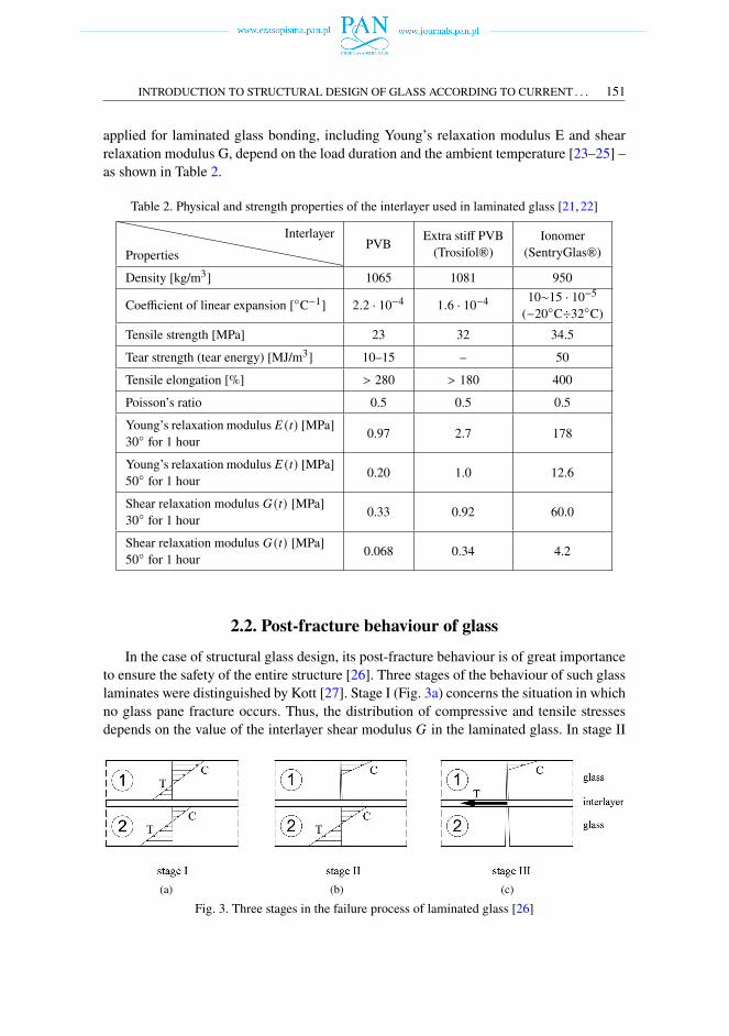
In the case of structural glass design, its post-fracture behaviour is of great importanceto ensure the safety of the entire structure [26]. Three stages of the behaviour of such glasslaminates were distinguished by Kott [27]. Stage I (Fig. 3a) concerns the situation in whichno glass pane fracture occurs. Thus, the distribution of compressive and tensile stressesdepends on the value of the interlayer shear modulus 𝐺 in the laminated glass. In stage II
(a) (b) (c)
Fig. 3. Three stages in the failure process of laminated glass [26]
152 A. JÓŹWIK
(Fig. 3b), one of the two glass panes is broken. Then, the tensile stresses at bending aretaken over by the undamaged glass sheet. In the third stage (Fig. 3c), the second layer ofglass is damaged. Compressive stresses can be residually borne by glass shards, while theinterlayer can only counterbalance tensile stresses. Hence, properties in terms of the tearstrength of the interlayers are of great importance, as high tensile elongation or tear usuallyleads the laminated glass being destroyed.
3. Structural glass in European standards and guidelines
The interest in possible structural glass applications led to the commencement of workson normative documents concerning methods to design glass structures [28, 29]. Thesedocuments, though often given only national status, may also be applied outside a coun-try due to the lack of supplementary guidelines. Among the first regulations concerningthe design of structural glass, the following guidelines may be mentioned: TRLV [30],TRPV [31], TRAV [32], published since 1998 by Deutsches Institut für Bautechnik (DIBt).The provisions contained in the abovementioned regulations concerned the use of glass inrelatively simple and common cases. The first of the documents, i.e., the TRLV, concernedlinearly supported glazing, whereas the TRAV discussed issues related to the design ofprotective barriers. The TRPV, in turn, presented ways to design point fixed glazing. Thesedocuments featured the key concept of glass calculation, based on the allowable stressmethod, with a global safety factor. A number of conditions failed to be included in theadopted method, which resulted in the design of enlarged cross-sections.Since 2010, the guidelines published by DIBt have been systematically replaced with
a national standard, i.e., DIN 18008 Glass In Building – Design and Construction Rules,with the following parts [33]:– Part 1: Terms and general bases [34],– Part 2: Linearly supported glazing [35],– Part 3: Point fixed glazing [36],– Part 4: Additional requirements for safety-barrier glazing [37],– Part 5: Additional requirements for walk-on glazing [38],– Part 6: Additional requirements for walk-on glazing in the case of maintenanceprocedures and for fall-through glazing [39],
– Part 7: Special structures (in preparation).The DIN 18008 standard presents a different approach to the concept of safety, which is
based on partial safety factors for material, geometry, loading, load and resistance side. Thisconcept is consistent with the European construction standards: the Eurocodes. The DIN18008 standard indicates limit states as the main method to calculate structural glass [33,40, 41]. The verification of glazed elements consists in the examination of the ultimatelimit state (ULS) and the serviceability limit state (SLS). According to its assumptions,the DIN 18008 standard was supposed to provide experience and entail the establishmentof a harmonised European standard, that is, the Eurocode 10 for the design of glassstructures [28, 40].
INTRODUCTION TO STRUCTURAL DESIGN OF GLASS ACCORDING TO CURRENT . . . 153
Currently, work on the Eurocode 10 is underway at the European Committee forStandardization (CEN). With this purpose in view, a special team was formed. Within theCEN/TC 250/SC 11 [42] committee named “Structural Glass”, the team developed the draftpre-standard prCEN/TS 19100 on structural glass [11]. The draft pre-standard is currentlybeing processed. It has been divided into parts [43]:
– Part 1: Basis of design and materials [44],– Part 2: Design of out-of-plane loaded glass components [45],– Part 3: Design of in-plane loaded components and their mechanical joints [46].As part of this pre-standard, the classification of structural elements was proposed to
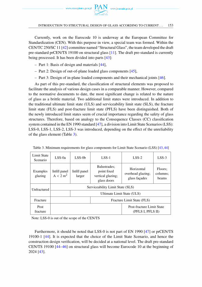
facilitate the analysis of various design cases in a comparable manner. However, comparedto the normative documents to date, the most significant change is related to the natureof glass as a brittle material. Two additional limit states were introduced. In addition tothe traditional ultimate limit state (ULS) and serviceability limit state (SLS), the fracturelimit state (FLS) and post-fracture limit state (PFLS) have been distinguished. Both ofthe newly introduced limit states seem of crucial importance regarding the safety of glassstructures. Therefore, based on analogy to the Consequence Classes (CC) classificationsystem contained in the EN 1990 standard [47], a division into Limit State Scenarios (LSS):LSS-0, LSS-1, LSS-2, LSS-3 was introduced, depending on the effect of the unreliabilityof the glass element (Table 3).
Table 3. Minimum requirements for glass components for Limit State Scenario (LSS) [43, 44]
Limit StateScenario LSS-0a LSS-0b LSS-1 LSS-2 LSS-3
Examplesglazing
Infill panelA < 2 m2
Infill panellarger
Balustrades;point fixed
vertical glazing;glass doors
Horizontaloverhead glazing;glass façades
Floors;columns;beams
UnfracturedServiceability Limit State (SLS)
Ultimate Limit State (ULS)
Fracture Fracture Limit State (FLS)
Postfracture
Post-fracture Limit State(PFLS I, PFLS II)
Note: LSS-0 is out of the scope of the CEN/TS
Furthermore, it should be noted that LSS-0 is not part of EN 1990 [47] or prCEN/TS19100-1 [44]. It is expected that the choice of the Limit State Scenario, and hence theconstruction design verification, will be decided at a national level. The draft pre-standardCEN/TS 19100 [44–46] on structural glass will become Eurocode 10 at the beginning of2024 [43].
154 A. JÓŹWIK
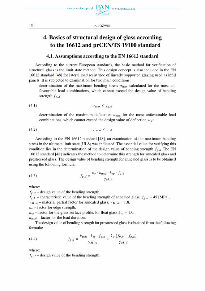
4. Basics of structural design of glass accordingto the 16612 and prCEN/TS 19100 standard
4.1. Assumptions according to the EN 16612 standard
According to the current European standards, the basic method for verification ofstructural glass is the limit state method. This design concept is also included in the EN16612 standard [48] for lateral load resistance of linearly supported glazing used as infillpanels. It is subjected to examination for two main conditions:– determination of the maximum bending stress 𝜎max calculated for the most un-favourable load combinations, which cannot exceed the design value of bendingstrength 𝑓𝑔,𝑑:
(4.1) 𝜎max ≤ 𝑓𝑔,𝑑
– determination of the maximum deflection 𝑤max for the most unfavourable loadcombinations, which cannot exceed the design value of deflection 𝑤𝑑:
(4.2) 𝑊max ≤ 𝑊𝑑
According to the EN 16612 standard [48], an examination of the maximum bendingstress in the ultimate limit state (ULS) was indicated. The essential value for verifying thiscondition lies in the determination of the design value of bending strength 𝑓𝑔,𝑑 The EN16612 standard [48] indicates the method to determine this strength for annealed glass andprestressed glass. The design value of bending strength for annealed glass is to be obtainedusing the following formula:
(4.3) 𝑓𝑔,𝑑 =𝑘𝑒 · 𝑘mod · 𝑘sp · 𝑓𝑔,𝑘
𝛾𝑀,𝐴
where:𝑓𝑔,𝑑 – design value of the bending strength,𝑓𝑔,𝑘 – characteristic value of the bending strength of annealed glass, 𝑓𝑔,𝑘 = 45 [MPa],𝛾𝑀,𝐴 – material partial factor for annealed glass, 𝛾𝑀,𝐴 = 1.8,𝑘𝑒 – factor for edge strength,𝑘sp – factor for the glass surface profile, for float glass 𝑘sp = 1.0,𝑘mod – factor for the load duration.The design value of bending strength for prestressed glass is obtained from the following
formula:
(4.4) 𝑓𝑔,𝑑 =𝑘mod · 𝑘sp · 𝑓𝑔,𝑘
𝛾𝑀,𝐴
+𝑘𝑣
(𝑓𝑏,𝑘 − 𝑓𝑔,𝑘
)𝛾𝑀,𝑉
where:𝑓𝑔,𝑑 – design value of the bending strength,
INTRODUCTION TO STRUCTURAL DESIGN OF GLASS ACCORDING TO CURRENT . . . 155
𝑓𝑔,𝑘 , 𝛾𝑀,𝐴, 𝑘mod; 𝑘sp – are described in formula (4.3),𝑓𝑏,𝑘 – characteristic value of the bending for prestressed glass, accord to Table 1,𝛾𝑀,𝑉 – material partial factor for prestressed glass 𝛾𝑀,𝑉 = 1.2,𝑘𝑉 – factor for strengthening of prestressed glass, for float glass 𝑘𝑉 = 1.0.It should also be noted that in formula (4.3), the edge strength 𝑘𝑒 factor related to the
location of the stresses was distinguished. The value thereof is influenced by the glass typeand by the quality of its edges. In the case that the glass is supported on its four edges, thefactor value equals 1.0. However, the value may amount to less than 1.0, e.g., should theglass sheet be supported on only two of its edges.In determining the design value of the bending strength for glass, the important element
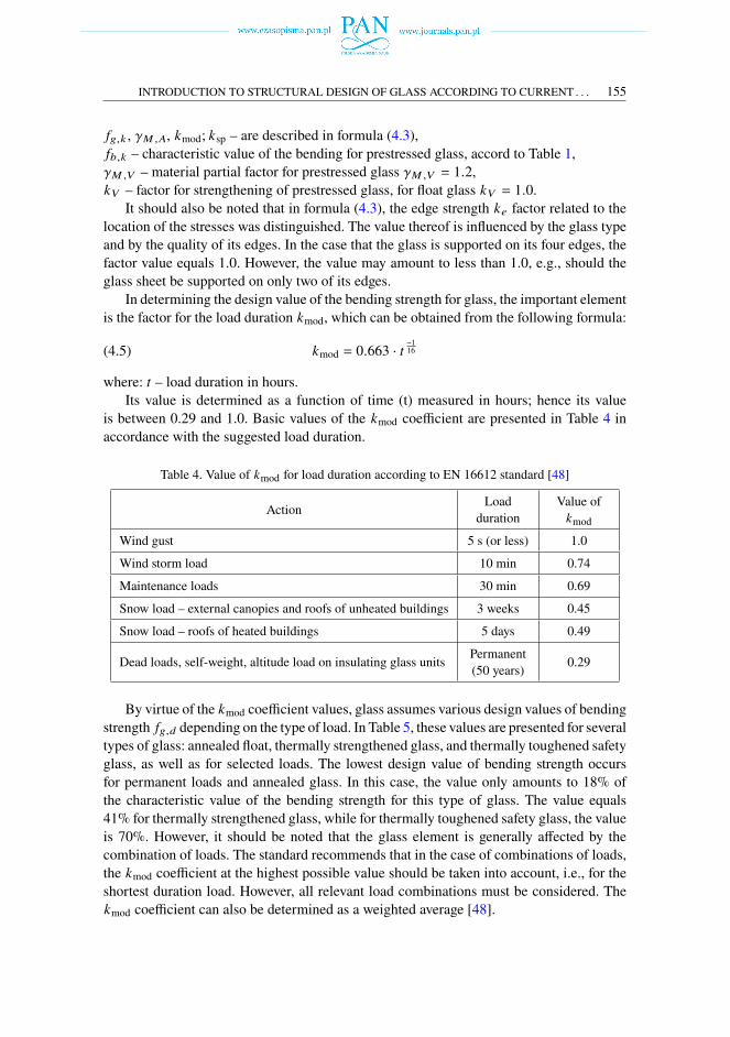
is the factor for the load duration 𝑘mod, which can be obtained from the following formula:
(4.5) 𝑘mod = 0.663 · 𝑡−116
where: 𝑡 – load duration in hours.Its value is determined as a function of time (t) measured in hours; hence its value
is between 0.29 and 1.0. Basic values of the 𝑘mod coefficient are presented in Table 4 inaccordance with the suggested load duration.
Table 4. Value of 𝑘mod for load duration according to EN 16612 standard [48]
Action Loadduration
Value of𝑘mod
Wind gust 5 s (or less) 1.0
Wind storm load 10 min 0.74
Maintenance loads 30 min 0.69
Snow load – external canopies and roofs of unheated buildings 3 weeks 0.45
Snow load – roofs of heated buildings 5 days 0.49
Dead loads, self-weight, altitude load on insulating glass units Permanent(50 years) 0.29
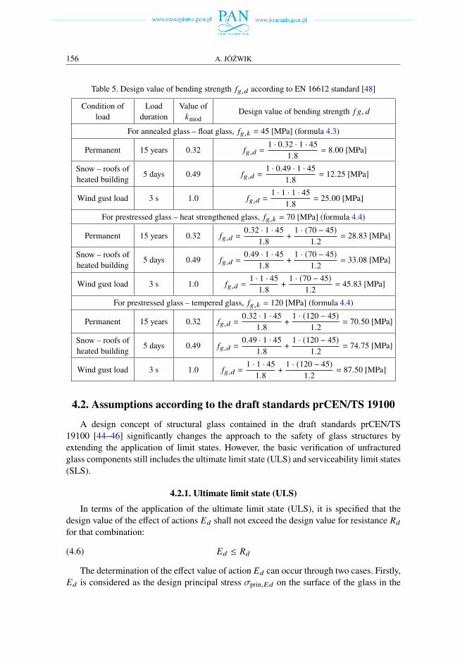
By virtue of the 𝑘mod coefficient values, glass assumes various design values of bendingstrength 𝑓𝑔,𝑑 depending on the type of load. In Table 5, these values are presented for severaltypes of glass: annealed float, thermally strengthened glass, and thermally toughened safetyglass, as well as for selected loads. The lowest design value of bending strength occursfor permanent loads and annealed glass. In this case, the value only amounts to 18% ofthe characteristic value of the bending strength for this type of glass. The value equals41% for thermally strengthened glass, while for thermally toughened safety glass, the valueis 70%. However, it should be noted that the glass element is generally affected by thecombination of loads. The standard recommends that in the case of combinations of loads,the 𝑘mod coefficient at the highest possible value should be taken into account, i.e., for theshortest duration load. However, all relevant load combinations must be considered. The𝑘mod coefficient can also be determined as a weighted average [48].
156 A. JÓŹWIK
Table 5. Design value of bending strength 𝑓𝑔,𝑑 according to EN 16612 standard [48]
Condition ofload
Loadduration
Value of𝑘mod
Design value of bending strength 𝑓 𝑔, 𝑑
For annealed glass – float glass, 𝑓𝑔,𝑘 = 45 [MPa] (formula 4.3)
Permanent 15 years 0.32 𝑓𝑔,𝑑 =1 · 0.32 · 1 · 45
1.8= 8.00 [MPa]
Snow – roofs ofheated building 5 days 0.49 𝑓𝑔,𝑑 =
1 · 0.49 · 1 · 451.8
= 12.25 [MPa]
Wind gust load 3 s 1.0 𝑓𝑔,𝑑 =1 · 1 · 1 · 451.8
= 25.00 [MPa]
For prestressed glass – heat strengthened glass, 𝑓𝑔,𝑘 = 70 [MPa] (formula 4.4)
Permanent 15 years 0.32 𝑓𝑔,𝑑 =0.32 · 1 · 451.8
+ 1 · (70 − 45)1.2
= 28.83 [MPa]
Snow – roofs ofheated building 5 days 0.49 𝑓𝑔,𝑑 =
0.49 · 1 · 451.8
+ 1 · (70 − 45)1.2
= 33.08 [MPa]
Wind gust load 3 s 1.0 𝑓𝑔,𝑑 =1 · 1 · 451.8
+ 1 · (70 − 45)1.2
= 45.83 [MPa]
For prestressed glass – tempered glass, 𝑓𝑔,𝑘 = 120 [MPa] (formula 4.4)
Permanent 15 years 0.32 𝑓𝑔,𝑑 =0.32 · 1 · 451.8
+ 1 · (120 − 45)1.2
= 70.50 [MPa]
Snow – roofs ofheated building 5 days 0.49 𝑓𝑔,𝑑 =
0.49 · 1 · 451.8
+ 1 · (120 − 45)1.2
= 74.75 [MPa]
Wind gust load 3 s 1.0 𝑓𝑔,𝑑 =1 · 1 · 451.8
+ 1 · (120 − 45)1.2
= 87.50 [MPa]
4.2. Assumptions according to the draft standards prCEN/TS 19100
A design concept of structural glass contained in the draft standards prCEN/TS19100 [44–46] significantly changes the approach to the safety of glass structures byextending the application of limit states. However, the basic verification of unfracturedglass components still includes the ultimate limit state (ULS) and serviceability limit states(SLS).
4.2.1. Ultimate limit state (ULS)In terms of the application of the ultimate limit state (ULS), it is specified that the
design value of the effect of actions 𝐸𝑑 shall not exceed the design value for resistance 𝑅𝑑
for that combination:
(4.6) 𝐸𝑑 ≤ 𝑅𝑑
The determination of the effect value of action 𝐸𝑑 can occur through two cases. Firstly,𝐸𝑑 is considered as the design principal stress 𝜎prin,𝐸𝑑 on the surface of the glass in the
INTRODUCTION TO STRUCTURAL DESIGN OF GLASS ACCORDING TO CURRENT . . . 157
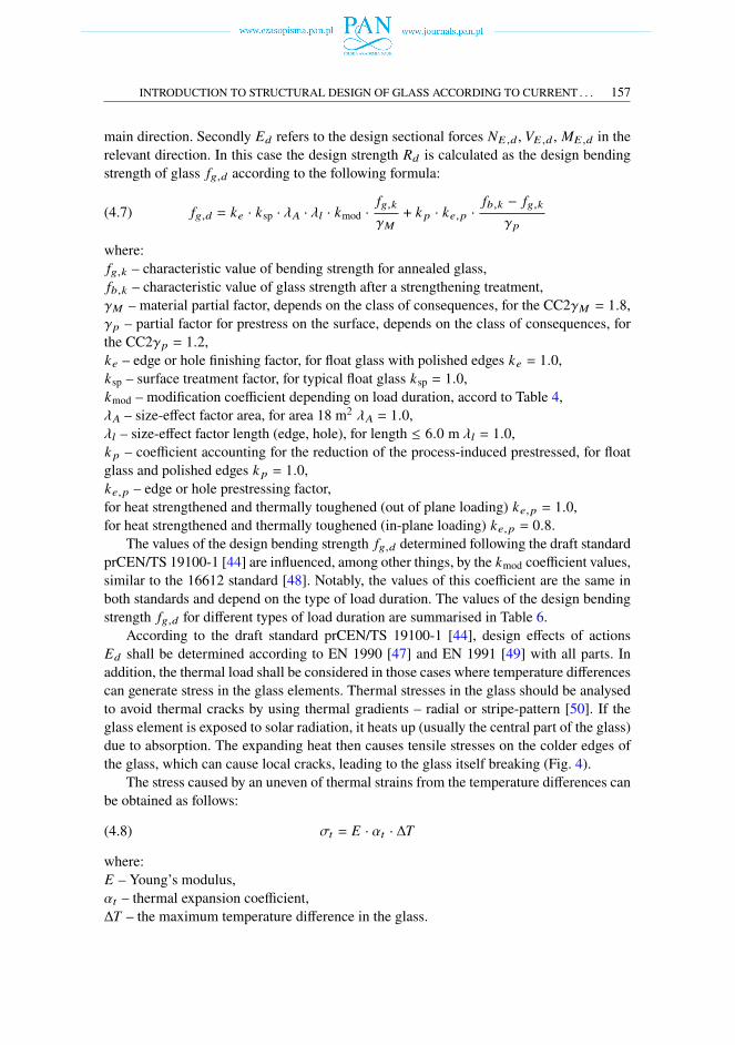
main direction. Secondly 𝐸𝑑 refers to the design sectional forces 𝑁𝐸,𝑑 , 𝑉𝐸,𝑑 , 𝑀𝐸,𝑑 in therelevant direction. In this case the design strength 𝑅𝑑 is calculated as the design bendingstrength of glass 𝑓𝑔,𝑑 according to the following formula:
(4.7) 𝑓𝑔,𝑑 = 𝑘𝑒 · 𝑘sp · _𝐴 · _𝑙 · 𝑘mod ·𝑓𝑔,𝑘
𝛾𝑀+ 𝑘 𝑝 · 𝑘𝑒,𝑝 ·
𝑓𝑏,𝑘 − 𝑓𝑔,𝑘
𝛾𝑝
where:𝑓𝑔,𝑘 – characteristic value of bending strength for annealed glass,𝑓𝑏,𝑘 – characteristic value of glass strength after a strengthening treatment,𝛾𝑀 – material partial factor, depends on the class of consequences, for the CC2𝛾𝑀 = 1.8,𝛾𝑝 – partial factor for prestress on the surface, depends on the class of consequences, forthe CC2𝛾𝑝 = 1.2,𝑘𝑒 – edge or hole finishing factor, for float glass with polished edges 𝑘𝑒 = 1.0,𝑘sp – surface treatment factor, for typical float glass 𝑘sp = 1.0,𝑘mod – modification coefficient depending on load duration, accord to Table 4,_𝐴 – size-effect factor area, for area 18 m2 _𝐴 = 1.0,_𝑙 – size-effect factor length (edge, hole), for length ≤ 6.0 m _𝑙 = 1.0,𝑘 𝑝 – coefficient accounting for the reduction of the process-induced prestressed, for floatglass and polished edges 𝑘 𝑝 = 1.0,𝑘𝑒,𝑝 – edge or hole prestressing factor,for heat strengthened and thermally toughened (out of plane loading) 𝑘𝑒,𝑝 = 1.0,for heat strengthened and thermally toughened (in-plane loading) 𝑘𝑒,𝑝 = 0.8.The values of the design bending strength 𝑓𝑔,𝑑 determined following the draft standard
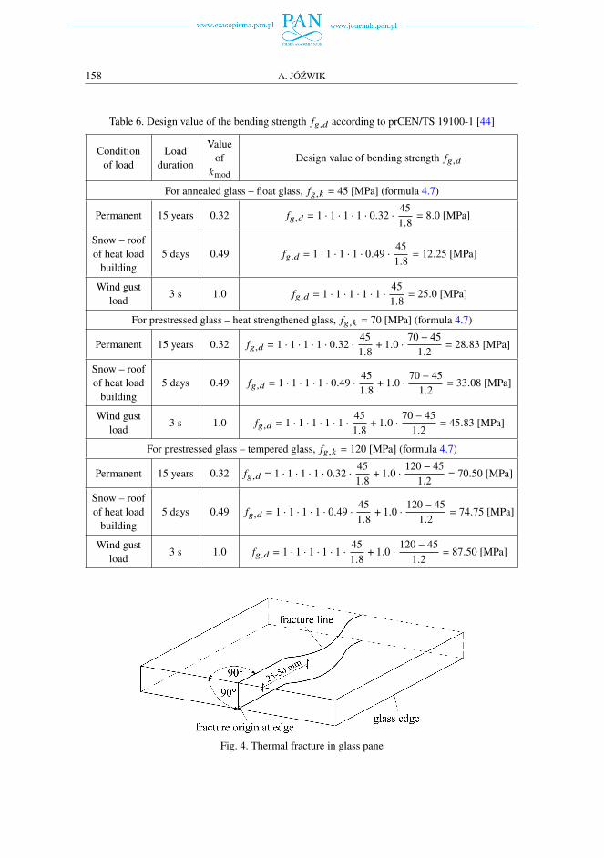
prCEN/TS 19100-1 [44] are influenced, among other things, by the 𝑘mod coefficient values,similar to the 16612 standard [48]. Notably, the values of this coefficient are the same inboth standards and depend on the type of load duration. The values of the design bendingstrength 𝑓𝑔,𝑑 for different types of load duration are summarised in Table 6.According to the draft standard prCEN/TS 19100-1 [44], design effects of actions
𝐸𝑑 shall be determined according to EN 1990 [47] and EN 1991 [49] with all parts. Inaddition, the thermal load shall be considered in those cases where temperature differencescan generate stress in the glass elements. Thermal stresses in the glass should be analysedto avoid thermal cracks by using thermal gradients – radial or stripe-pattern [50]. If theglass element is exposed to solar radiation, it heats up (usually the central part of the glass)due to absorption. The expanding heat then causes tensile stresses on the colder edges ofthe glass, which can cause local cracks, leading to the glass itself breaking (Fig. 4).The stress caused by an uneven of thermal strains from the temperature differences can
be obtained as follows:
(4.8) 𝜎𝑡 = 𝐸 · 𝛼𝑡 · Δ𝑇
where:𝐸 – Young’s modulus,𝛼𝑡 – thermal expansion coefficient,Δ𝑇 – the maximum temperature difference in the glass.
158 A. JÓŹWIK
Table 6. Design value of the bending strength 𝑓𝑔,𝑑 according to prCEN/TS 19100-1 [44]
Conditionof load
Loadduration
Valueof𝑘mod
Design value of bending strength 𝑓𝑔,𝑑
For annealed glass – float glass, 𝑓𝑔,𝑘 = 45 [MPa] (formula 4.7)
Permanent 15 years 0.32 𝑓𝑔,𝑑 = 1 · 1 · 1 · 1 · 0.32 · 451.8
= 8.0 [MPa]
Snow – roofof heat loadbuilding
5 days 0.49 𝑓𝑔,𝑑 = 1 · 1 · 1 · 1 · 0.49 · 451.8
= 12.25 [MPa]
Wind gustload 3 s 1.0 𝑓𝑔,𝑑 = 1 · 1 · 1 · 1 · 1 · 45
1.8= 25.0 [MPa]
For prestressed glass – heat strengthened glass, 𝑓𝑔,𝑘 = 70 [MPa] (formula 4.7)
Permanent 15 years 0.32 𝑓𝑔,𝑑 = 1 · 1 · 1 · 1 · 0.32 · 451.8
+ 1.0 · 70 − 451.2
= 28.83 [MPa]
Snow – roofof heat loadbuilding
5 days 0.49 𝑓𝑔,𝑑 = 1 · 1 · 1 · 1 · 0.49 · 451.8
+ 1.0 · 70 − 451.2
= 33.08 [MPa]
Wind gustload 3 s 1.0 𝑓𝑔,𝑑 = 1 · 1 · 1 · 1 · 1 · 45
1.8+ 1.0 · 70 − 45
1.2= 45.83 [MPa]
For prestressed glass – tempered glass, 𝑓𝑔,𝑘 = 120 [MPa] (formula 4.7)
Permanent 15 years 0.32 𝑓𝑔,𝑑 = 1 · 1 · 1 · 1 · 0.32 · 451.8
+ 1.0 · 120 − 451.2
= 70.50 [MPa]
Snow – roofof heat loadbuilding
5 days 0.49 𝑓𝑔,𝑑 = 1 · 1 · 1 · 1 · 0.49 · 451.8
+ 1.0 · 120 − 451.2
= 74.75 [MPa]
Wind gustload 3 s 1.0 𝑓𝑔,𝑑 = 1 · 1 · 1 · 1 · 1 · 45
1.8+ 1.0 · 120 − 45
1.2= 87.50 [MPa]
Fig. 4. Thermal fracture in glass pane
INTRODUCTION TO STRUCTURAL DESIGN OF GLASS ACCORDING TO CURRENT . . . 159
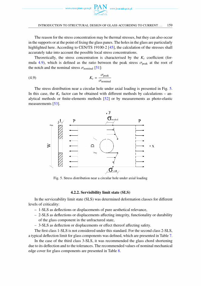
The reason for the stress concentration may be thermal stresses, but they can also occurin the supports or at the point of fixing the glass panes. The holes in the glass are particularlyhighlighted here. According to CEN/TS 19100-2 [45], the calculation of the stresses shallaccurately take into account the possible local stress concentrations.Theoretically, the stress concentration is characterised by the 𝐾𝑡 coefficient (for-
mula 4.9), which is defined as the ratio between the peak stress 𝜎peak at the root ofthe notch and the nominal stress 𝜎nominal [51]:
(4.9) 𝐾𝑡 =𝜎peak
𝜎nominal
The stress distribution near a circular hole under axial loading is presented in Fig. 5.In this case, the 𝐾𝑡 factor can be obtained with different methods by calculations – an-alytical methods or finite-elements methods [52] or by measurements as photo-elasticmeasurements [53].
Fig. 5. Stress distribution near a circular hole under axial loading
4.2.2. Servisibility limit state (SLS)
In the serviceability limit state (SLS) was determined deformation classes for differentlevels of criticality:– 1-SLS as deflections or displacements of pure aesthetical relevance,– 2-SLS as deflections or displacements affecting integrity, functionality or durabilityof the glass component in the unfractured state,
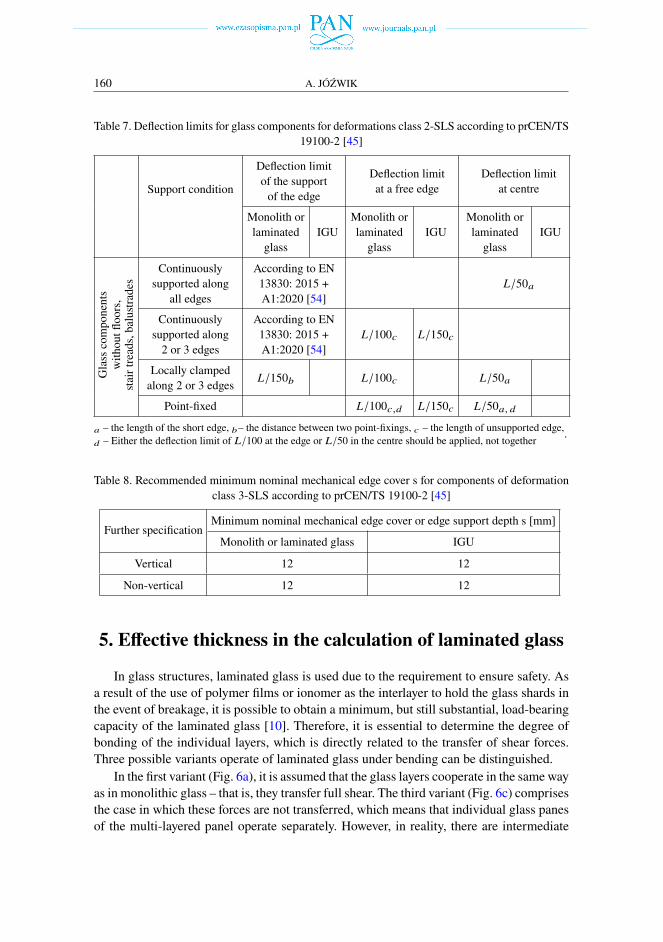
– 3-SLS as deflection or displacements or effect thereof affecting safety.The first class 1-SLS is not considered under this standard. For the second class 2-SLS,
a typical deflection limit for glass components was defined, which are presented in Table 7.In the case of the third class 3-SLS, it was recommended the glass chord shortening
due to its deflection and to the tolerances. The recommended values of nominal mechanicaledge cover for glass components are presented in Table 8.
160 A. JÓŹWIK
Table 7. Deflection limits for glass components for deformations class 2-SLS according to prCEN/TS19100-2 [45]
Support condition
Deflection limitof the supportof the edge
Deflection limitat a free edge
Deflection limitat centre
Monolith orlaminatedglass
IGUMonolith orlaminatedglass
IGUMonolith orlaminatedglass
IGU
Glasscomponents
withoutfloors,
stairtreads,balustrades
Continuouslysupported alongall edges
According to EN13830: 2015 +A1:2020 [54]
𝐿/50𝑎
Continuouslysupported along2 or 3 edges
According to EN13830: 2015 +A1:2020 [54]
𝐿/100𝑐 𝐿/150𝑐
Locally clampedalong 2 or 3 edges 𝐿/150𝑏 𝐿/100𝑐 𝐿/50𝑎
Point-fixed 𝐿/100𝑐,𝑑 𝐿/150𝑐 𝐿/50𝑎, 𝑑𝑎 – the length of the short edge, 𝑏– the distance between two point-fixings, 𝑐 – the length of unsupported edge,𝑑 – Either the deflection limit of 𝐿/100 at the edge or 𝐿/50 in the centre should be applied, not together
.
Table 8. Recommended minimum nominal mechanical edge cover s for components of deformationclass 3-SLS according to prCEN/TS 19100-2 [45]
Further specificationMinimum nominal mechanical edge cover or edge support depth s [mm]
Monolith or laminated glass IGU
Vertical 12 12
Non-vertical 12 12
5. Effective thickness in the calculation of laminated glass
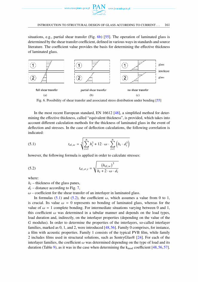
In glass structures, laminated glass is used due to the requirement to ensure safety. Asa result of the use of polymer films or ionomer as the interlayer to hold the glass shards inthe event of breakage, it is possible to obtain a minimum, but still substantial, load-bearingcapacity of the laminated glass [10]. Therefore, it is essential to determine the degree ofbonding of the individual layers, which is directly related to the transfer of shear forces.Three possible variants operate of laminated glass under bending can be distinguished.In the first variant (Fig. 6a), it is assumed that the glass layers cooperate in the same way
as in monolithic glass – that is, they transfer full shear. The third variant (Fig. 6c) comprisesthe case in which these forces are not transferred, which means that individual glass panesof the multi-layered panel operate separately. However, in reality, there are intermediate
INTRODUCTION TO STRUCTURAL DESIGN OF GLASS ACCORDING TO CURRENT . . . 161
situations, e.g., partial shear transfer (Fig. 6b) [55]. The operation of laminated glass isdetermined by the shear transfer coefficient, defined in various ways in standards and sourceliterature. The coefficient value provides the basis for determining the effective thicknessof laminated glass.
(a) (b) (c)
Fig. 6. Possibility of shear transfer and associated stress distribution under bending [55]
In the most recent European standard, EN 16612 [48], a simplified method for deter-mining the effective thickness, called “equivalent thickness”, is provided, which takes intoaccount different calculation methods for the thickness of laminated glass in the event ofdeflection and stresses. In the case of deflection calculations, the following correlation isindicated:
(5.1) 𝑡ef,𝑤 = 3
√√𝑛∑︁𝑖=1
ℎ3𝑖 + 12 · 𝜔 ·𝑛∑︁𝑖=1
(ℎ𝑖 · 𝑑3𝑖
)however, the following formula is applied in order to calculate stresses:
(5.2) 𝑡ef,𝜎,𝑖 =
√︄ (ℎef,𝑤
)3ℎ𝑖 + 2 · 𝜔 · 𝑑𝑖
where:ℎ𝑖 – thickness of the glass panes,𝑑𝑖 – distance according to Fig. 7,𝜔 – coefficient for the shear transfer of an interlayer in laminated glass.In formulas (5.1) and (5.2), the coefficient 𝜔, which assumes a value from 0 to 1,
is crucial. Its value 𝜔 = 0 represents no bonding of laminated glass, whereas for thevalue of 𝜔 = 1 complete bonding. For intermediate situations varying between 0 and 1,this coefficient 𝜔 was determined in a tabular manner and depends on the load types,load duration and, indirectly, on the interlayer properties (depending on the value of the𝐺 modulus). In order to determine the properties of the interlayers, so-called interlayerfamilies, marked as 0, 1, and 2, were introduced [48,56]. Family 0 comprises, for instance,a film with acoustic properties. Family 1 consists of the typical PVB film, while family2 includes films used in structural solutions, such as SentryGlas® [24]. For each of theinterlayer families, the coefficient 𝜔 was determined depending on the type of load and itsduration (Table 9), as it was in the case when determining the kmod coefficient [48,56,57].
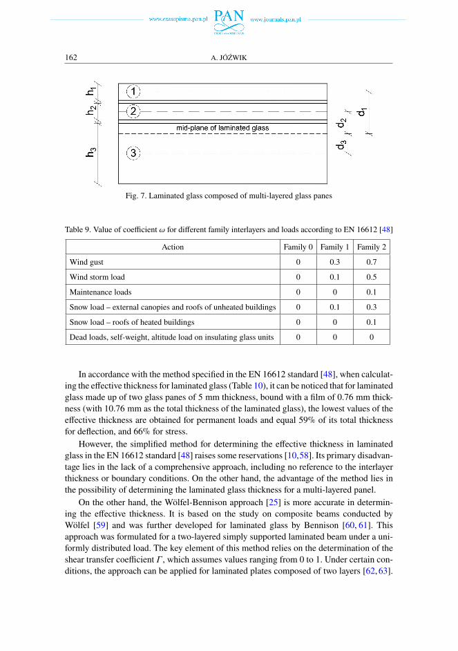
162 A. JÓŹWIK
Fig. 7. Laminated glass composed of multi-layered glass panes
Table 9. Value of coefficient 𝜔 for different family interlayers and loads according to EN 16612 [48]
Action Family 0 Family 1 Family 2
Wind gust 0 0.3 0.7
Wind storm load 0 0.1 0.5
Maintenance loads 0 0 0.1
Snow load – external canopies and roofs of unheated buildings 0 0.1 0.3
Snow load – roofs of heated buildings 0 0 0.1
Dead loads, self-weight, altitude load on insulating glass units 0 0 0
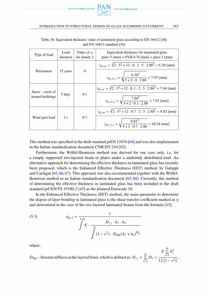
In accordance with the method specified in the EN 16612 standard [48], when calculat-ing the effective thickness for laminated glass (Table 10), it can be noticed that for laminatedglass made up of two glass panes of 5 mm thickness, bound with a film of 0.76 mm thick-ness (with 10.76 mm as the total thickness of the laminated glass), the lowest values of theeffective thickness are obtained for permanent loads and equal 59% of its total thicknessfor deflection, and 66% for stress.However, the simplified method for determining the effective thickness in laminated
glass in the EN 16612 standard [48] raises some reservations [10,58]. Its primary disadvan-tage lies in the lack of a comprehensive approach, including no reference to the interlayerthickness or boundary conditions. On the other hand, the advantage of the method lies inthe possibility of determining the laminated glass thickness for a multi-layered panel.On the other hand, the Wölfel-Bennison approach [25] is more accurate in determin-
ing the effective thickness. It is based on the study on composite beams conducted byWölfel [59] and was further developed for laminated glass by Bennison [60, 61]. Thisapproach was formulated for a two-layered simply supported laminated beam under a uni-formly distributed load. The key element of this method relies on the determination of theshear transfer coefficient 𝛤, which assumes values ranging from 0 to 1. Under certain con-ditions, the approach can be applied for laminated plates composed of two layers [62, 63].
INTRODUCTION TO STRUCTURAL DESIGN OF GLASS ACCORDING TO CURRENT . . . 163
Table 10. Equivalent thickness value of laminated glass according to EN 16612 [48]and EN 16613 standard [56]
Type of load Loadduration
Value of 𝜔for family 2
Equivalent thickness for laminated glassglass 5 [mm] + PVB 0.76 [mm] + glass 5 [mm]
Permanent 15 years 0𝑡ef,𝑤 =
3√︁2 · 53 + 12 · 0 · 2 · 5 · 2.882 = 6.30 [mm]
𝑡ef,𝜎,𝑖 =
√︄6.303
5 + 2 · 0 · 2.88 = 7.07 [mm]
Snow – roofs ofheated buildings 5 days 0.1
𝑡ef,𝑤 =3√︁2 · 53 + 12 · 0, 1 · 2 · 5 · 2.882 = 7.04 [mm]
𝑡ef,𝜎,𝑖 =
√︂7.043
5 + 2 · 0.1 · 2.88 = 7.91 [mm]
Wind gust load 3 s 0.7𝑡ef,𝑤 =
3√︁2 · 53 + 12 · 0.7 · 2 · 5 · 2.882 = 9.82 [mm]
𝑡ef,𝜎,𝑖 =
√︂9.823
5 + 2 · 0.7 · 2.88 = 10.24 [mm]
This method was specified in the draft standard prEN 13474 [64] and was also implementedin the Italian standardisation document CNR-DT-210 [65].Furthermore, the Wölfel-Bennison method was derived for one case only, i.e. for
a simply supported two-layered beam or plates under a uniformly distributed load. Analternative approach for determining the effective thickness in laminated glass has recentlybeen proposed, which is the Enhanced Effective Thickness (EET) method, by Galuppiand Carfagni [62,66,67]. This approach was also recommended together with the Wölfel-Bennison method in an Italian standardisation document [65, 68]. Currently, this methodof determining the effective thickness in laminated glass has been included in the draftstandard prCEN/TS 19100-2 [45] as the planned Eurocode 10.In the Enhanced Effective Thickness (EET) method, the main parameter to determine
the degree of layer bonding in laminated glass is the shear transfer coefficient marked as [and determined in the case of the two-layered laminated beams from the formula [45]:
(5.3) [𝑝,2 =1
1+ℎ∫𝐸 ·
𝐷 | | · ℎ1 · ℎ2𝐺∫(1 − 𝜐2) · 𝐷full (ℎ1 + ℎ2)Ψ𝑝
where:
𝐷abs – flexural stiffness at the layered limit, which is defined as:𝐷 | | =𝑛∑𝑖=1𝐷𝑖 =
𝐸𝑛∑𝑖=1ℎ3𝑖
12(1 − a2
) ,
164 A. JÓŹWIK
𝐷full –flexural stiffness at themonolith limit,which is defined as:𝐷full =𝐷 | |+𝐸
𝑛∑𝑖=1
(ℎ𝑖 · 𝑑2𝑖
)(1 − a2
) ,
ℎ1, ℎ2, ℎ𝑖 – glass thickness,𝑑𝑖 – is distance accord to Fig. 7,ℎint – interlayer thickness,𝐸 – Young’s modulus of the glass,𝐺 int – shear modulus of the interlayer,a – Poisson coefficient,𝜓𝑝 – boundary coefficient for plates.The shear transfer coefficient [ in formula (5.3) depends on the glass and the polymer
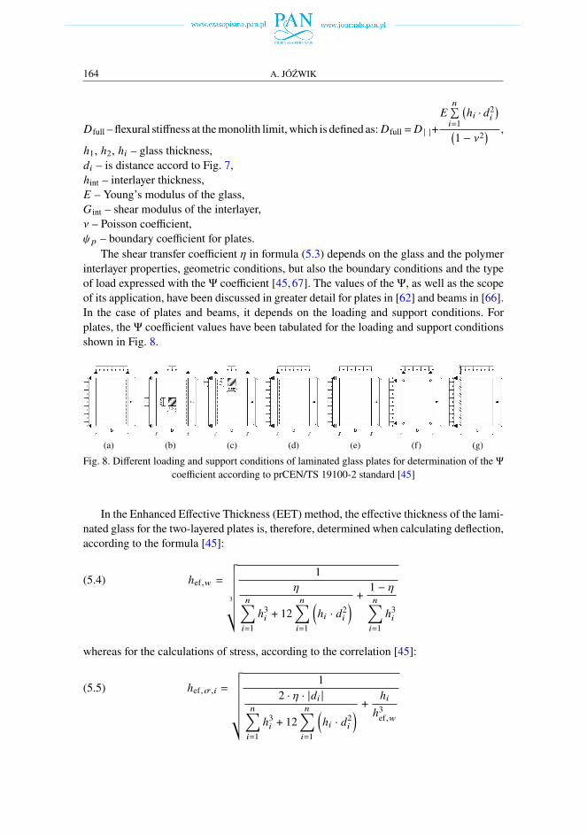
interlayer properties, geometric conditions, but also the boundary conditions and the typeof load expressed with the Ψ coefficient [45,67]. The values of the Ψ, as well as the scopeof its application, have been discussed in greater detail for plates in [62] and beams in [66].In the case of plates and beams, it depends on the loading and support conditions. Forplates, the Ψ coefficient values have been tabulated for the loading and support conditionsshown in Fig. 8.
(a) (b) (c) (d) (e) (f) (g)
Fig. 8. Different loading and support conditions of laminated glass plates for determination of the Ψcoefficient according to prCEN/TS 19100-2 standard [45]
In the Enhanced Effective Thickness (EET) method, the effective thickness of the lami-nated glass for the two-layered plates is, therefore, determined when calculating deflection,according to the formula [45]:
(5.4) ℎef,𝑤 =
3
√√√√√√√√√√√ 1[
𝑛∑︁𝑖=1
ℎ3𝑖 + 12𝑛∑︁𝑖=1
(ℎ𝑖 · 𝑑2𝑖
) + 1 − [𝑛∑︁𝑖=1
ℎ3𝑖
whereas for the calculations of stress, according to the correlation [45]:
(5.5) ℎef,𝜎,𝑖 =
√√√√√√√√√√√ 12 · [ · |𝑑𝑖 |
𝑛∑︁𝑖=1
ℎ3𝑖 + 12𝑛∑︁𝑖=1
(ℎ𝑖 · 𝑑2𝑖
) + ℎ𝑖
ℎ3ef,𝑤
INTRODUCTION TO STRUCTURAL DESIGN OF GLASS ACCORDING TO CURRENT . . . 165
When calculating the effective thickness for a laminated glass plate in accordancewith prCEN/TS 19100-2 [45], its geometry, loading and support conditions are taken intoaccount. For a panel with dimensions of 1.5× 2.0 m and supported on four edges (Fig. 6a),theΨ coefficient is 6.969×10⁻⁶ mm2 [45]. This glass is composed of two 5 mm thick glasslayers glued with 0.76 mm PVB film. For such assumptions and for the wind load gustload (3 s), the shear transfer coefficient [𝑝,2 = 0.8042 (𝐺 inst = 0.8 MPa for time duration3 s and temperature 50◦C). The effective thickness for deflection is then ℎef,𝑤 = 9.31 mm,while for stresses, it takes the value ℎef,𝜎 = 10.04 mm.
The Enhanced Effective Thickness (EET) method is now being developed not onlyfor two-layered plates or beams [45], but also for other specifications such as multi-layered laminated glass [58], curved laminated glass [69], and cantilevered laminated glassbalustrades [70].
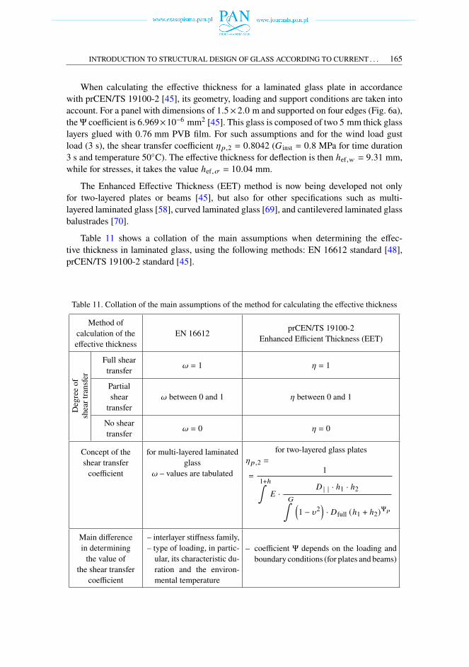
Table 11 shows a collation of the main assumptions when determining the effec-tive thickness in laminated glass, using the following methods: EN 16612 standard [48],prCEN/TS 19100-2 standard [45].
Table 11. Collation of the main assumptions of the method for calculating the effective thickness
Method ofcalculation of theeffective thickness
EN 16612 prCEN/TS 19100-2Enhanced Efficient Thickness (EET)
Degreeof
sheartransfer
Full sheartransfer 𝜔 = 1 [ = 1
Partialsheartransfer
𝜔 between 0 and 1 [ between 0 and 1
No sheartransfer 𝜔 = 0 [ = 0
Concept of theshear transfercoefficient
for multi-layered laminatedglass
𝜔 – values are tabulated
for two-layered glass plates[𝑝,2 =
=1
1+ℎ∫𝐸 ·
𝐷 | | · ℎ1 · ℎ2𝐺∫ (1 − 𝜐2
)· 𝐷full (ℎ1 + ℎ2)Ψ𝑝
Main differencein determiningthe value of
the shear transfercoefficient
– interlayer stiffness family,– type of loading, in partic-ular, its characteristic du-ration and the environ-mental temperature
– coefficient Ψ depends on the loading andboundary conditions (for plates and beams)
166 A. JÓŹWIK
6. Conclusions
Glass structures present a significant engineering challenge. Glass, as a brittle material,and works differently than typical structural materials that may work in the elastic or plasticstage. Therefore, it is essential to understand its strength properties and the nature of thestatic works of glass structural elements.According to the European normative documents currently in force, great attention is
paid to ensuring the safety of structures. If glass structures are to be implemented, it iscrucial to use laminated glass technology as it maintains a residual load capacity in post-fracture conditions. Hence, it is assumed that the additional limit states will be introducedin the planned Eurocode 10 devoted to the design of glass structures. In addition to theultimate limit state (ULS), and serviceability limit state (SLS), the fracture limit state(FLS), and the post-fracture limit state (PFLS) will be introduced.Due to the operation of laminated glass within the structural element, the interlayer
and its strength properties have a significant influence. The new generation polymer andionomer interlayers are characterised by better strength properties [71]. However, it shouldbe emphasised at this point that the properties of suchmaterials depend on the load durationand ambient temperature. Thus, further research is required due to the operation time ofglass structures.The European standards currently in force indicate methods for calculating laminated
glass working as coupled or uncoupled or in an intermediate situation of glass sheets;therefore, the so-called effective thickness is calculated. However, it should be emphasisedthat the method for calculating effective thickness that is presented in the standards aremost useful in the design of glass plates. In the case of other elements, the situation is morecomplicated. One of the reasons is the direction of load, i.e., out-of-plane or in-plane. Onthe other hand, the direction of the glass layers is also important, which can be horizontalor vertical. Also, in this respect, further research is required.
References[1] C.J. De Lima, F. Veer, O. Çopuroglu, R. Nijsee, “Advancements and Challenges in Glass Concepts, Man-ufacturing and Applications”, presented at 13th International Congress on Advances in Civil Engineering,12-14 Sep. 2018, Izmir, 2018.
[2] Ch. Schittisch, “Glass Pavilion at Broadfield House in Kingswinford Architecture”, in Auf Den ZweitenBlick / Architecture and the Test of Time, K. Arima, et. al. Munich: Detail, 2012.
[3] M. Marchewka, “Advances in the Use of Structural Glass”, in Challenging Glass 2: Conference on Archi-tectural and Structural Applications on Glass, J. Bos, Ch. Louter, R. Veer, Eds. Delf, 2010.
[4] J. O’Callaghan, “Adventures with Structural Glass”, Glass Performance Days, South Africa, 2012.[5] Ch. Bedon, M. Santarsiero, “Transparency in Structural Glass Transparency Via Mechanical Adhesive andLaminated Connections – Existing Research and Developments”, Advanced Engineering Materials, 2018,vol. 20, no. 5, pp. 1–18, DOI: 10.1002/adem.201700815.
[6] M. Teich. Ch. Bauchinger, “Aktuelle Entwicklungen und Konstruktionstechniken für Glasfassaden”,Bautechnik, 2020, vol. 97, pp. 338–343, DOI: 10.1002/bate.202000014.
[7] A. Jóźwik, “O możliwościach zastosowania szkła w elementach konstrukcyjnych”, Inżynieria i Budown-ictwo, 2017, vol. 9, pp. 459–462.
INTRODUCTION TO STRUCTURAL DESIGN OF GLASS ACCORDING TO CURRENT . . . 167
[8] TU0905 – Structural Glass – Novel design methods and next generation products. [Online]. Available:https://www.cost.eu/actions/TU0905/. [Accessed: 10.07.2021].
[9] M. Feldman, R. Kasper, et al., Guidance for European Structural Design of Glass Components. 2014.[10] M. Kozłowski, Balustrady szklane. Analizy doświadczalne obliczeniowe, podstawy projektowania. Gliwice:
Wydawnictwo Politechniki Śląskiej, 2019.[11] H. Zobel, “Normalizacja w procesie projektowania w budownictwie”. [Online]. Available: https://
www.piib.org.pl/ aktualnosci/informacje-biezace/4472-normalizacja-w-procesie-projektowania-w-budownictwie. [Accessed: 10.07.2021].
[12] M. Haldimann, A. Luible , M. Overen, Structural use of glass. Zürich: IABSE, 2008.[13] N.I. Min’ko, V.M. Nartsev, “Factors Affecting the Strength of the Glass”,Middle-East Journal of Scientific
Research, 2013, vol. 18, no. 11, pp. 1616–1624.[14] A.A. Griffith, “The phenomena of rupture and flow in solids”, Philosophical Transactions of the Royal
Society A: Mathematical, Physical and Engineering Sciences, 1921, vol. 221, no. 582–593, DOI: 10.1098/rsta.1921.0006.
[15] EN 572-1:2012+A1:2016 Glass in building – Basic soda lime silicate glass products – Part 1: Definitionsand general physical and mechanical properties.
[16] EN 1863-1:2011 Glass in building – Heat strengthened soda lime silicate glass – Part 1: Definition anddescription.
[17] EN 12150-1:2015+A1:2019 Glass in building – Thermally toughened soda lime silicate safety glass – Part1: Definition and description.
[18] EN 12337-1:2000 Glass in building – Chemically strengthened soda lime silicate glass – Part 1: Definitionand description.
[19] M. Martin, X. Centelles, A. Solé, C. Barreneche, A.I. Fernández, L.F. Cabeza, “Polymeric inter-layer materials for laminated glass: A review”, Construction and Building Materials, 2020, vol. 230,DOI: 10.1016/j.conbuildmat.2019.116897.
[20] J. Schneider, “Performance Comparision of Structural Interlayers”, in Challenging Glass 6: Confer-ence on Architectural and Structural Applications on Glass, Ch. Louter, et al., Eds., 2018, vol. 6,DOI: 10.7480/cgc.6.2202.
[21] Trosifol®Architectural Glazing for architects, designers, engineers and consultants. [Online]. Avail-able: https://www.trosifol.com/fileadmin/user_upload/TROSIFOL/support/downloads/product_brochures/pdf_documents/architecture/Trosifol_SentryGlas_Architectural-Glazing.pdf. [Accessed: 10.07.2021].
[22] SentryGlas® Ionoplast Interlayer. [Online]. Available: https://www.trosifol.com/fileadmin/user_upload/technical_information/downloads/sentryglas/150129_Kuraray_TM_Datenblatt_SG.pdf. [Accessed:10.07.2021].
[23] W.M. Stevels, P.D. Haene, P. Zhang, S. Haldeman, “A Comparison of Different Methodologies for PVBInterlayer Modulus Characterization”, in Challenging Glass 5: Conference on Architectural and StructuralApplications on Glass, vol. 5, J. Belis, F. Bos, Ch. Louter, Eds. Ghent, 2016, DOI: 10.7480/cgc.5.2266.
[24] W.M. Stevels, “PVB Interlayer Modulus Properties in Contemporary European Standards”, Glass Perfor-mance Days. Tampere, 2019, pp. 56–60.
[25] M. Gwóźdź, Konstrukcje szklane i aluminiowo-szklane. Kraków: Wydawnictwo Politechniki Krakowskiej,2020.
[26] J. Belis, J. Depauw, D. Callewaert, D. Delincé, R. Van Impe, “Failure mechanisms and residual capacity ofannealed glass/SGP laminated beams at room temperature”, Engineering Failure Analysis, 2009, vol. 16,no. 6, pp. 1866–1875, DOI: 10.1016/j.engfailanal.2008.09.023.
[27] A. Kott, “Zum Trag- und Resttragverhalten von Verbundsicherheitsglas”, Doctoral Thesis ETH Zürich,2006, Prof. T. Vogel, Prof. Dr. K. Begmeister, DOI: 10.3929/ethz-a-005170632.
[28] G. Siebert, “Aktueller Stand der Glasnormung”, Stahlabu, 2015, vol. 84, no. S1, pp. 21–29, DOI: 10.1002/stab.201590079.
[29] T. Wüest, A. Luible, “Glass Design in Switzerland”, in Challenging Glass 7, vol. 7, J. Belis, F. Bos,Ch. Louter, Eds. Ghent, 2020, DOI: 10.7480/cgc.7.4610.
168 A. JÓŹWIK
[30] TRLV Technische Regeln für die Verwendung von linienförmig gelagerten Verglasungen (Technical rulesfor the use of glazing with linear supports), DIBt, August 2006.
[31] TRPV Technische Regeln für die Bemessung und Ausführung punktförmig gelagerter Verglasungen (Tech-nical rules for the use of glazing with supports at individual points), DIBt, August 2006.
[32] TRAV Technische Regeln für die Verwendung von absturzsichernden Verglasungen (Technical rules for theuse of safety-barier glazing), DIBt, January 2003.
[33] A. Haese, G. Siebert, “DIN 18008 – Experience after one year of applying the new German glass designstandard”, in Challenging Glass 5: Conference on Architectural and Structural Applications on Glass,J. Belis, F. Bos, Ch. Louter, Eds. Ghent, 2016, DOI: 10.7480/cgc.5.2288.
[34] DIN 18008-1:2010-12 (currently DIN 18008-1:2020-05)Glass in building – Design and construction rules– Part 1: Terms and general bases.
[35] DIN 18008-2:2010-12 (currently DIN 18008-1:2020-05)Glass in building – Design and construction rules– Part 2: Linearly supported glazing.
[36] DIN 18008-3:2013-07 Glass in building – Design and construction rules – Part 3: Point fixed glazing.[37] DIN 18008-4:2013-07 Glass in building – Design and construction rules – Part 4: Additional requirement
for safety-barrier glazing.[38] DIN 18008-5:2013-07 Glass in building – Design and construction rules – Part 5: Additional requirement
for walk-on glazing.[39] DIN 18008-6:2018-02 Glass in building – Design and construction rules – Part 6: Additional requirement
for walk-on glazing in case of maintenance procedures and for fall-through glazing.[40] G. Siebert, “Comparison of IGU-design according to German and European Standards”, Engineered Trans-
parency 2018: Glass in Architectural Engineering, 2018, vol. 2, no. 5-6, pp. 81–92, DOI: 10.1002/cepa.912.[41] G. Siebert, M. Botz, M.A. Kraus, “Comparison of LSG-design according to German and European Stan-
dards”, in: Engineered Transparency 2018. Glass in Architecture and Structural Engineering, J. Schneider,B. Weller, Eds. Berlin: Ernst und Sohn, 2018, vol. 2, no. 5-6, pp. 93–102, DOI: 10.1002/cepa.913.
[42] A. Piekarczuk, “Projektowanie konstrukcji ze szkła budowlanego. Dokumenty normatywne”, Budownictwoi Prawo, 2018, vol. 21, no. 2, pp. 10–13.
[43] M. Feldmann, P. Di Biase, “The CEN-ST "Structural Glass – Design and Construction" as pre-standard forthe Eurocode”, Ce/papers, 2018, vol. 3, no. 1, pp. 73–82, DOI: 10.1002/cepa.1001.
[44] CEN/TS 19100-1:2021 Design of glass structures – Part 1: Basis of design and materials.[45] CEN/TS 19100-2:2021Design of glass structures – Part 2: Design of out-of-plane loaded glass components.[46] CEN/TS 19100-3:2021 Design of glass structures – Part 3: Design of in-plane loaded glass components
and their mechanics joints.[47] EN 1990:2002+A1:2005 Eurocode – Basis of structural design.[48] EN16612:2019Glass in building – Determination of the lateral load resistance of glass panes by calculation.[49] EN 1991 Eurocode 1: Actions on structures.[50] P. Foraboschi, “Analytical modeling to predict thermal shock failure and maximum temperature gradients
of a glass panel”, Material & Design, 2017, vol. 134, pp. 301–319, DOI: 10.1016/j.matdes.2017.08.021.[51] J. Schijve, Fatigue of Structures and Materials. Dordrecht: Springer, 2009.[52] N. Pourmoghaddam, J. Schneider, “Finite-element analysis of the residual stresses in tempered glass plates
with holes or cut-outs”, Glass Structural Engineering, 2018, no. 3, pp. 17–37, DOI: 10.1007/s40940-018-0055-z.
[53] G. Šaučiuvenas, T. Gečys, A. Mudrov, L. Ustinovichius, Cz. Miedzialowski, “The analysis of stress distri-bution in tempered structural glass with stress concentrators under tension and compression”, Archives ofCivil and Mechanical Engineering, 2020, vol.20, no. 3, pp. 66–77, DOI: 10.1007/s43452-020-00067-5.
[54] EN 13830:2015 +A1:2020 Curtatin walling – Product standard.[55] J. Kuntsche, M. Schuster, J. Schneider, “Engineering design of laminated safety glass considering the shear
coupling: a review”, Glass Structural Engineering, 2019, vol. 4, pp. 209–228, DOI: 10.1007/s40940-019-00097-3.
INTRODUCTION TO STRUCTURAL DESIGN OF GLASS ACCORDING TO CURRENT . . . 169
[56] EN 16613:2019Glass in building – Laminate glass and laminated safety glass – Determination of interlayerviscoelastic properties.
[57] M.A. Kraus, M. Botz, G. Siebert, “Structural Design of Laminated Glass Under Consideration of the ShearCoupling According to German, European an US Standards”, Conference paper GlassCon Global, Chicago,2018.
[58] L. Galuppi, G. Royer-Carfagni, “Enhanced Effective Thickness of multi-layered laminated glass”, Compos-ites Part B: Engineering, 2014, vol. 64, pp. 202–213, DOI: 10.1016/j.compositesb.2014.04.018.
[59] E.Wölfel, “Nachgiebiger Verbund Eine Näherungslösung und deren Anwendungsmöglichkeiten”, Stahlbau,1987, vol. 56, no. 6, pp. 173–180.
[60] S.J. Bennison, I. Stelzer, “Structural properties of laminated glass. Short course”, Glass Performance Days,Tampere, 2009.
[61] I. Calderone, P.S. Davies, S.J. Bennison, H. Xiaokun, L. Gang, “Effective laminated thickness for the designof laminated glass”, Glass Performance Days, Tampere, 2009, pp. 1–3.
[62] L. Galuppi, G. Royer-Carfagni, “The effective thickness of laminated glass plates”, Journal of Mechanicsof Materials and Structures, 2012, vol. 7, no. 4, pp. 375–400, DOI: 10.2140/jomms.2012.7.375.
[63] M. Gwóźdź, P. Woźniczka, “New static analysis methods for plates made of monolithic and laminatedglass”, Archives of Civil Engineering, 2020, vol. 66, no. 4, pp. 593–603, DOI: 10.24425/ace.2020.135239.
[64] EN 13474-1:1999 Glass in building – Design of glass panes – Part1: General basis of glass.[65] CNR-DT 201:2013 Istruzioni per la Progettazione, l’Esecuzione ed il Controllo di Costruzioni con Elementi
Strutturali di Vetro (Guide for the Design, Construction and Control of Buildings with Structural GlassElements).
[66] L. Galuppi, G. Royer-Carfagni, “Effective thickness of laminated glass beams: New expression via a varia-tional approach”, Engineering Structures, 2012, vol. 38, pp. 53–67, DOI: 10.1016/j.engstruct.2011.12.039.
[67] L. Galuppi, G. Royer-Carfagni, “Practical expressions for the design of laminated glass”, Composites: PartB, 2013, vol. 45, no. 1, pp. 1677–1688, DOI: 10.1016/j.compositesb.2012.09.073.
[68] L. Galuppi, G. Royer-Carfagni, “The effective thickness of laminated glass: Inconsistency of the formulationin proposal of EN-standards”,Composites: Part B, 2013, vol. 55, pp. 109–118, DOI: 10.1016/j.compositesb.2013.05.025.
[69] L. Galuppi, G. Royer-Carfagni, “Enhanced effective thickness (EET) of curved laminated glass”, AnnalsSolid Structural Mechanics, 2015, vol. 7, pp. 71–92, DOI: 10.1007/s12356-015-0043-9.
[70] A. Nizich, L. Galuppi, “Enhanced Effective Thickness method for Cantilevered Laminated GlassBalustrades”, Glass Performance Days, Tampere, 2019, pp. 398–401.
[71] J. Schneider, “Next generation ionoplast for improved lamination”, Glass Performance Days, Tampere,2019, pp. 61–63.
Wprowadzenie do projektowania szkła konstrukcyjnegowedług aktualnych norm europejskich
Słowa kluczowe: konstrukcje szklane, szkło konstrukcyjne, szkło laminowane, EN 16612, CEN/TS-19100, Eurkokod 10
Streszczenie:
Szkło jest materiałem powszechnie stosowanym w budownictwie. Rozwój jego technologii orazwzrost wiedzy dotyczącej właściwości mechanicznych i wytrzymałościowych sprzyja również moż-liwościom stosowania szkła jako materiału konstrukcyjnego. Konstrukcyjne zastosowanie szkła jestszczególnie istotne dla kształtowania rozwiązań architektonicznych, w których transparentność sta-nowi szczególną cechę estetyczną.
170 A. JÓŹWIK
Wraz z rozwojem konstrukcji szklanych są opracowywane metody ich projektowania oraz wy-tyczne i normy w tym zakresie. W artykule scharakteryzowano podstawowe właściwości szkła jakomateriału konstrukcyjnego. Ponadto omówiono główne założenia wytycznych niemieckich TRxV,serii niemieckich norm DIN 18008 oraz norm europejskich (mających również status polskich norm)PN-EN 16612 wraz z EN 16613. Artykułprzedstawia także koncepcję projektowania szkła kon-strukcyjnego zawartą w projekcie normy CEN/TS 19100, która stanowi podstawę opracowaniazharmonizowanej normy Europejskiej – Eurokodu 10 dotyczącego projektowania konstrukcji szkla-nych. Zgodnie z tą prenormą szklane elementy konstrukcyjne będą weryfikowane ze względu naich bezpieczeństwo w oparciu o cztery stany graniczne w zależności od tzw. klasy konsekwencjipęknięć. Oprócz klasycznych stanów granicznych, tj. stanu granicznego nośności i stanu granicznegoużytkowalności, zakłada się również wprowadzenie stanu granicznego pęknięcia i stanu granicznegopo pęknięciu.W artykule poruszono także kwestię pracy szkła laminowanego w elementach konstrukcyjnych.
W zależności od stopnia zespolenia tafli szklanych i międzywarst polimerowych lub jonomerowych,możnawyróżnić szkło laminowane całkowicie zespolone, lub niezespolone, a także pracujące w sytu-acjach pośrednich. Biorąc pod uwagę charakter pracy szkła laminowanego, przy jego projektowaniuoblicza się tzw. grubość efektywną.W artykule omówionometody wyznaczania grubości efektywnejzawarte w europejskich normach i wytycznych.
Received: 02.08.2021, Revised: 20.09.2021