Designing of a wireless gesture-controlled robot
49
Visvesvaraya Technological University Belgaum, Karnataka-590 018 A Project Report on “Designing of a wireless gesture-controlled robot” Project Report submitted in partial fulfillment of the requirement for the award of the degree of Bachelor of Engineering In Electrical & Electronics Engineering Submitted by Gaurish Ninnekar 1CR16EE026 Kumar Shubham 1CR15EE043 Abhishek Kumar 1CR16EE002 Under the Guidance of Mrs. ANJU DAS Assistant Professor, Department of Electrical & Electronics Engineering CMR Institute of Technology CMR Institute of Technology, Bengaluru-560 037 Department of Electrical & Electronics Engineering 2020-2021 i
-
Upload
khangminh22 -
Category
Documents
-
view
1 -
download
0
Transcript of Designing of a wireless gesture-controlled robot
Visvesvaraya Technological University
Belgaum, Karnataka-590 018
A Project Report on
“Designing of a wireless gesture-controlled robot”
Project Report submitted in partial fulfillment of the requirement for the award of the degree of
Bachelor of Engineering In
Electrical & Electronics Engineering
Submitted by
Gaurish Ninnekar 1CR16EE026
Kumar Shubham 1CR15EE043
Abhishek Kumar 1CR16EE002
Under the Guidance of Mrs. ANJU DAS
Assistant Professor, Department of Electrical & Electronics Engineering
CMR Institute of Technology
CMR Institute of Technology, Bengaluru-560 037
Department of Electrical & Electronics Engineering
2020-2021
i
CMR INSTITUTE OF TECHNOLOGY DEPARTMENT OF ELECTRICAL & ELECTRONICS ENGINEERING
AECS Layout, Bengaluru-560 037
Certificate
Certified that the project work entitled “Designing of a wireless gesture controlled robot”
carried out by Mr. Gaurish Ninnekar,(1CR16EE026); Mr. Kumar Shubham,
(1CR15EE043); Mr. Abhishek Kumar,(1CR16EE002) are bonafied students of CMR
Institute of Technology, Bengaluru, in partial fulfillment for the award of Bachelor of
Engineering in Electrical & Electronics Engineering of the Visvesvaraya Technological
University, Belgaum, during the year 2020-2021. It is certified that all corrections/suggestions
indicated for Internal Assessment have been incorporated in the Report deposited in the
departmental library.
The project report has been approved as it satisfies the academic requirements in respect
of Project work prescribed for the said Degree.
Signature of the Guide
----------------------------- Mrs. ANJU DAS,
Assistant professor
EEE Department
CMRIT, Bengaluru
Signature of the HOD
-------------------------------- Dr. K. Chitra
Professor & HOD
EEE Department
CMRIT, Bengaluru
Signature of the Principal
----------------------------- Dr. Sanjay Jain
Principal,
CMRIT, Bengaluru
External Viva Name of the Examiners Signature & Date
1.
2.
ii

CMR INSTITUTE OF TECHNOLOY DEPARTMENT OF ELECTRICAL & ELECTRONICS ENGINEERING
AECS Layout, Bengaluru-560 037
DECLARATION
We, Mr. Gaurish Ninnekar (1CR16EE026); Mr.. Kumar Shubham (1CR15EE043); Mr.
Abhishek Kumar (1CR16EE002) hereby declare that the report entitled “Designing of a
wireless gesture controlled robot” has been carried out by us under the guidance of ANJU
DAS, Assistant professor , Department of Electrical & Electronics Engineering, CMR Institute of
Technology, Bengaluru, in partial fulfillment of the requirement for the degree of BACHELOR OF
ENGINEERING in ELECTRICAL & ELECTRONICS ENGINEERING, of Visveswaraya
Technological University, Belagaum during the academic year 2020-21. The work done in this report
is original and it has not been submitted for any other degree in any university.
Place: Bengaluru
Date:
Gaurish N( 1CR16EE026)
Kumar Shubham (1CR15EE043)
Abhishek Kumar (1CR16EE002)
iii iii
Abstract
Gesture Controlled Car is a robot which can be controlled by simple human gestures. The user just needs to wear a
gesture device in which a sensor is included. The sensor will record the movement of hand in a specific direction which
will result in the motion of the robot in the respective directions. The robot and the Gesture instrument are connected
wirelessly through radio waves. User can interact with the robot in a more friendly way due to the wireless
communication. We can control the car using accelerometer sensors connected to a hand glove. The sensors are intended
to replace the remote control that is generally used to run the car. It will allow user to control the forward, backward,
leftward and rightward movements, while using the same accelerometer sensor to control the throttle of the car.
Movement of car is controlled by the differential mechanism. The mechanism involves the rotation of both forth & rear
wheels of left or right side to move in the anticlockwise direction and the other pair to rotate in the clockwise direction
which makes the car to rotate about its own axis without any kind of forward or backward motion. The main advantage
of this mechanism is the car with this mechanism can take sharp turn without any difficulty. The design and
implementation of a gesture control robotic arm using flex sensor is proposed. The robotic arm is designed in such a
way that it consists of four movable fingers, each with three linkages, an opposing thumb, a rotating wrist and an elbow.
The robotic arm is made to imitate the human hand movements using a hand glove.

Acknowledgement
The satisfaction and euphoria that accompany the successful completion of any task
would be incomplete without the mention of people, who are responsible for the completion
of the project and who made it possible, because success is outcome of hard work and
perseverance, but stead fast of all is encouraging guidance. So with gratitude we
acknowledge all those whose guidance and encouragement served us to motivate towards
the success of the project work.
We take great pleasure in expressing our sincere thanks to Dr. Sanjay Jain,
Principal, CMR Institute of Technology, Bengaluru for providing an excellent academic
environment in the college and for his continuous motivation towards a dynamic career. We
would like to profoundly thank Dr. B Narasimha Murthy, Vice-principal of CMR Institute
of Technology and the whole Management for providing such a healthy environment for the
successful completion of the project work.
We would like to convey our sincere gratitude to Dr. K Chitra, Head of Electrical
and Electronics Engineering Department, CMR Institute of Technology, Bengaluru for
her invaluable guidance and encouragement and for providing good facilities to carry out
this project work.
We would like to express our deep sense of gratitude to Mrs. Anju Das, Assistant
Professor, Electrical and Electronics Engineering, CMR Institute of Technology,
Bengaluru for his/her exemplary guidance, valuable suggestions, expert advice and
encouragement to pursue this project work.
We are thankful to all the faculties and laboratory staffs of Electrical and
Electronics Engineering Department, CMR Institute of Technology, Bengaluru for
helping us in all possible manners during the entire period.
Finally, we acknowledge the people who mean a lot to us, our parents, for their
inspiration, unconditional love, support, and faith for carrying out this work to the finishing
line. We want to give special thanks to all our friends who went through hard times together,
cheered us on, helped us a lot, and celebrated each accomplishment.
Lastly, to the Almighty, for showering His Blessings and to many more, whom we
didn’t mention here.
v
CONTENTS
Chapter Page no
1. Introduction 1
Background 2
Goal and objectives 2
2. Issues to Hand Gesture Recognition: Extraction Methods
And Features Extraction: 3
Extraction Method And Image Pre-Processing 3
3. Methodology 5
4. Hardware and software 8
5. RESULT 35
6. Conclusion 38
• Reference 39
LIST OF FIGURES.
SL. NO. PAGE NO.
1. Gesture recognition system steps 3
2. Gesture control block diagram 5
3. Receiver circuit 5
4. Transmitter circuit 6
5. Arduino board 8
6. Arduino pin diagram 9
7. Power regulator IC 11
8. Circuit diagram of power regulation unit 11
9. Motor controller driver: L293D 12
10. Dc motor 14
11. Cables and wires 14
12. Transmitter and receiver board 16
13. Robotic chassis and batteries 17
14. Hand controller 35
15. Top view of car model 36
16. Portrait of view of card 37
Designing of a wireless gesture-controlled robot
ELECTRICAL & ELECTRONICS ENGG. CMRIT. 2020-2021 Page 1
CHAPTER 1
INTRODUCTION
1.1 Introduction
Hand gesture recognition system received great attention in the recent few years because of its
manifoldness applications and the ability to interact with machine efficiently through human computer
interaction.
Gesture recognition is a supportive requirement of disables and many other robotics works. So, the
researchers and companies try to implement an algorithm and make some gradates in this purpose.
Hand gesture recognition is used in human-robot interaction (HRI) to create user interfaces that are
natural to use and easy to learn. Sensors used for hand gesture recognition include wearable sensors such
as data gloves and external sensors such as video cameras. Data gloves can provide accurate
measurements of hand pose and movement, but they require extensive calibration, restrict natural hand
movement, and are often very expensive. Video-based gesture recognition addresses these issues but
presents a new problem: locating the hands and segmenting them from the background in an image
sequence is a non-trivial task, in particular when there are occlusions, lighting changes, rapid motion, or
other skin-colored objects in a scene. Depth images, either sensed directly with depth cameras such as
the Microsoft Kinect, ASUS Xtion, or Mesa Swiss Ranger, or extracted from stereo video cameras,
provide an alternative as they can function in several situations where video cameras cannot, such as in
low or unpredictable lighting, and in environments with skin colored objects other than the hands (such
as a face). However, there is no comprehensive study of the state of practice, such as reported in Watch’s
for applications of video-based hand gestures.

Designing of a wireless gesture-controlled robot
ELECTRICAL & ELECTRONICS ENGG. CMRIT. 2020-2021 Page 2
1.2 Background
Microcontroller Based Gesture Recognition and Angle Measurement without image processing
involves 9dof Accelerometer gyroscope magnetometer. Which can measure the X and Y axes rotation
and acceleration. The project was composed of main electronics circuits and electronic components such
as:
❖ Arduino Uno
❖ L293D Motor Controller Driver
❖ DC motor
❖ 433khz Wireless Radio transmitter and receiver.
❖ The system can give you both the angle and gesture of forward, backward, right and left.
1.3 Goals and Objective
❖ Measure the hand gesture
❖ Identify the movement direction
❖ Encode the gesture data and send via RF transmitter
❖ Receive via RF transmitter and decode.
❖ Move the robot with decoded data.
Designing of a wireless gesture-controlled robot
ELECTRICAL & ELECTRONICS ENGG. CMRIT. 2020-2021 Page 3
CHAPTER 2
Literature Review
2.1 Issues to Hand Gesture Recognition: Extraction Methods And Features
Extraction:
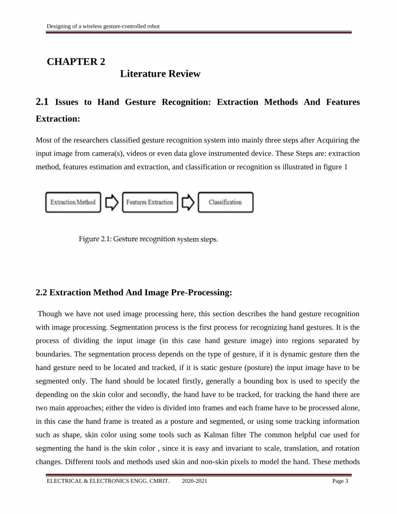
Most of the researchers classified gesture recognition system into mainly three steps after Acquiring the
input image from camera(s), videos or even data glove instrumented device. These Steps are: extraction
method, features estimation and extraction, and classification or recognition ss illustrated in figure 1
2.2 Extraction Method And Image Pre-Processing:
Though we have not used image processing here, this section describes the hand gesture recognition
with image processing. Segmentation process is the first process for recognizing hand gestures. It is the
process of dividing the input image (in this case hand gesture image) into regions separated by
boundaries. The segmentation process depends on the type of gesture, if it is dynamic gesture then the
hand gesture need to be located and tracked, if it is static gesture (posture) the input image have to be
segmented only. The hand should be located firstly, generally a bounding box is used to specify the
depending on the skin color and secondly, the hand have to be tracked, for tracking the hand there are
two main approaches; either the video is divided into frames and each frame have to be processed alone,
in this case the hand frame is treated as a posture and segmented, or using some tracking information
such as shape, skin color using some tools such as Kalman filter The common helpful cue used for
segmenting the hand is the skin color , since it is easy and invariant to scale, translation, and rotation
changes. Different tools and methods used skin and non-skin pixels to model the hand. These methods
Designing of a wireless gesture-controlled robot
ELECTRICAL & ELECTRONICS ENGG. CMRIT. 2020-2021 Page 4
are parametric and non-parametric techniques, Gaussian Model (GM) and Gaussian Mixture Model
(GMM) are parametric techniques, and histogram based techniques are nonparametric.
Rafiqul Zaman Khan and Noor Adnan Ibraheem of the Department of Computer Science, A.M.U.
Aligarh, India, in the International Journal of Intelligence and Artificial Applications (IJAIA) in July
2012 proposed hand signal recognition: a survey of writing. They said the hand motion recognition
framework had an amazing consideration in the couple of years because of their complex applications
and the ability to interact with the machine effectively through human collaboration with the PC. They
showed a review of the frames of recognition of last-minute movements. The key issues of the hand
signal recognition framework are given the difficulties of the structure of the movement.
Stefan Waldherr, Roseli Romero, Sebastian Thrun represents a movement interface for controlling a
versatile robot with a controller. The interface uses a camera to follow a man and perceive signals that
include arm movement. Subsequent and rapid calculation allows the robot to trace and reliably complete
a man in office situations with varying lighting conditions.
Designing of a wireless gesture-controlled robot
ELECTRICAL & ELECTRONICS ENGG. CMRIT. 2020-2021 Page 5
CHAPTER 3
METHODOLOGY
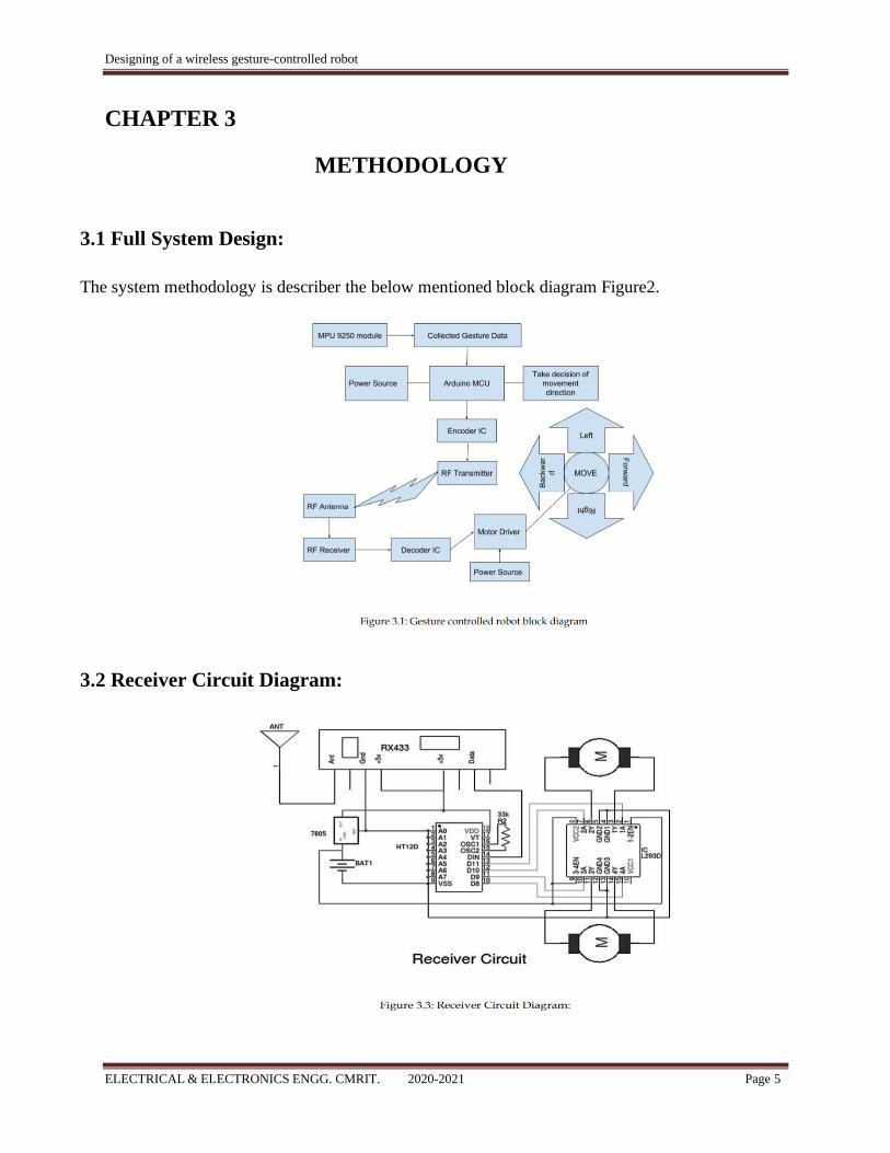
3.1 Full System Design:
The system methodology is describer the below mentioned block diagram Figure2.
3.2 Receiver Circuit Diagram:

Designing of a wireless gesture-controlled robot
ELECTRICAL & ELECTRONICS ENGG. CMRIT. 2020-2021 Page 6
3.3 Transmitter Circuit Diagram:
3.4 System Algorithm:
The full system follows the following algorithm:
1. Sensed the hand gesture movement from hand to microcontroller.
2. MCU receives the data and make instructions for the robot. Sends the instruction to the encoder
IC.
3. Encoded data transmits through the transmitter.
4. In the receivers end the receiver receives the encoded data.
5. Receiver sends the encoded data to the decoder.
6. Decoder decodes the data and sends to the motor driver.
7. Motor driver drives the motor in all movements by following the instruction and gestures.
8. Finally, the robot moves with the gestures.

Designing of a wireless gesture-controlled robot
ELECTRICAL & ELECTRONICS ENGG. CMRIT. 2020-2021 Page 7
CHAPTER 4
DESCRIPTION OF HARDWARE AND SOFTWARE
Different modules used in the project are discussed here thoroughly. The main hardware of this project
is microcontroller chip. The programming is written in C language. The method involves Arduino
microcontroller, MPU 6050, LCD monitor, etc. The tools that are used in the system can be dividing in
the following:
• Hardware
• Software
HARDWARE:
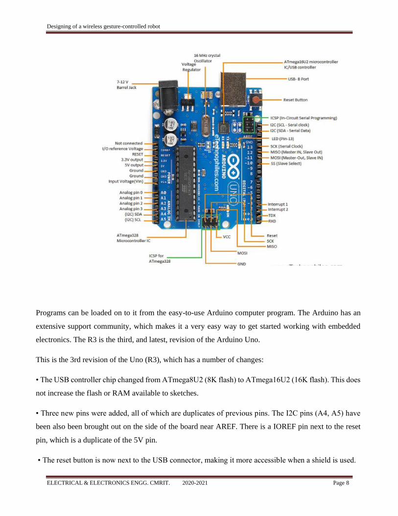
4.1 Arduino Uno:
The Arduino Uno R3 is a microcontroller board based on a removable, dual-inline-package (DIP) ATmega328 AVR
microcontroller.
It has 20 digital input/output pins (of which 6 can be used as PWM outputs and 6 can be used as analog inputs.
Designing of a wireless gesture-controlled robot
ELECTRICAL & ELECTRONICS ENGG. CMRIT. 2020-2021 Page 8
Programs can be loaded on to it from the easy-to-use Arduino computer program. The Arduino has an
extensive support community, which makes it a very easy way to get started working with embedded
electronics. The R3 is the third, and latest, revision of the Arduino Uno.
This is the 3rd revision of the Uno (R3), which has a number of changes:
• The USB controller chip changed from ATmega8U2 (8K flash) to ATmega16U2 (16K flash). This does
not increase the flash or RAM available to sketches.
• Three new pins were added, all of which are duplicates of previous pins. The I2C pins (A4, A5) have
been also been brought out on the side of the board near AREF. There is a IOREF pin next to the reset
pin, which is a duplicate of the 5V pin.
• The reset button is now next to the USB connector, making it more accessible when a shield is used.
Designing of a wireless gesture-controlled robot
ELECTRICAL & ELECTRONICS ENGG. CMRIT. 2020-2021 Page 9
More information about the Arduino Uno R3 is available on Arduino’s website.
4.2 Power Supply:
We used this power supply to charge our battery.
Power supply is a reference to a source of electrical power. A device or system that supplies electrical
or other types of energy to an output load or group of loads is called a power supply unit or PSU. The
term is most commonly applied to electrical energy supplies, less often to mechanical ones, and rarely to
others. Here in our application we need a 5v DC and 9-12v DC power supply for all electronics involved
in the project.
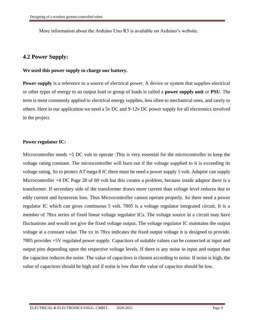
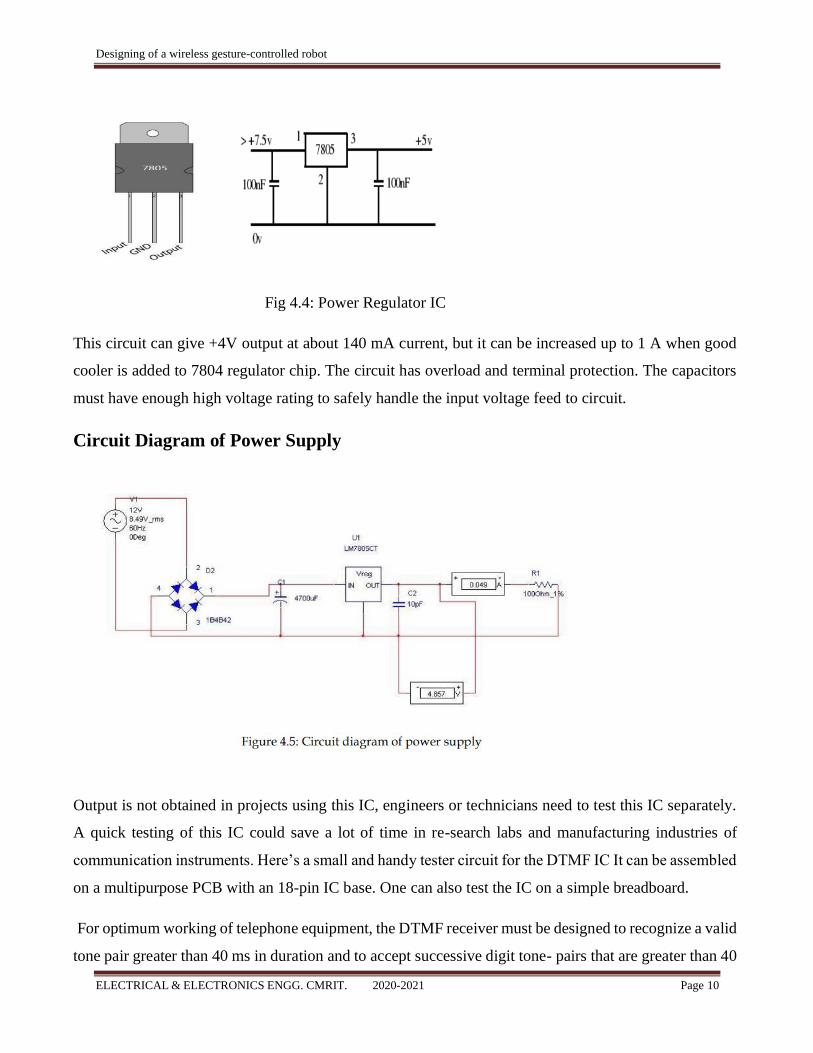
Power regulator IC:
Microcontroller needs +5 DC volt to operate .This is very essential for the microcontroller to keep the
voltage rating constant. The microcontroller will burn out if the voltage supplied to it is exceeding its
voltage rating. So to protect AT mega 8 IC there must be need a power supply 5 volt. Adaptor can supply
Microcontroller +4 DC Page 28 of 60 volt but this creates a problem, because inside adaptor there is a
transformer. If secondary side of the transformer draws more current than voltage level reduces due to
eddy current and hysteresis loss. Thus Microcontroller cannot operate properly. So there need a power
regulator IC which can gives continuous 5 volt. 7805 is a voltage regulator integrated circuit. It is a
member of 78xx series of fixed linear voltage regulator ICs. The voltage source in a circuit may have
fluctuations and would not give the fixed voltage output. The voltage regulator IC maintains the output
voltage at a constant value. The xx in 78xx indicates the fixed output voltage it is designed to provide.
7805 provides +5V regulated power supply. Capacitors of suitable values can be connected at input and
output pins depending upon the respective voltage levels. If there is any noise in input and output than
the capacitor reduces the noise. The value of capacitors is chosen according to noise. If noise is high, the
value of capacitors should be high and if noise is low than the value of capacitor should be low.
Designing of a wireless gesture-controlled robot
ELECTRICAL & ELECTRONICS ENGG. CMRIT. 2020-2021 Page 10
Fig 4.4: Power Regulator IC
This circuit can give +4V output at about 140 mA current, but it can be increased up to 1 A when good
cooler is added to 7804 regulator chip. The circuit has overload and terminal protection. The capacitors
must have enough high voltage rating to safely handle the input voltage feed to circuit.
Circuit Diagram of Power Supply
Output is not obtained in projects using this IC, engineers or technicians need to test this IC separately.
A quick testing of this IC could save a lot of time in re-search labs and manufacturing industries of
communication instruments. Here’s a small and handy tester circuit for the DTMF IC It can be assembled
on a multipurpose PCB with an 18-pin IC base. One can also test the IC on a simple breadboard.
For optimum working of telephone equipment, the DTMF receiver must be designed to recognize a valid
tone pair greater than 40 ms in duration and to accept successive digit tone- pairs that are greater than 40
Designing of a wireless gesture-controlled robot
ELECTRICAL & ELECTRONICS ENGG. CMRIT. 2020-2021 Page 11
ms apart. However, for other applications like remote controls and radio communications, the tone
duration may differ due to noise considerations. Therefore, by adding an extra resistor and steering diode
the tone duration can be set to different values. The circuit is configured in balanced-line mode. To reject
common-mode noise signals, a balanced differential amplifier input is used. The circuit also provides an
excellent bridging interface across a properly terminated telephone line. Transient protection may be
achieved by splitting the input resistors and inserting ZENER diodes (ZD1 and ZD2) to achieve voltage
clamping. This allows the transient energy to be dissipated in the resistors and diodes and limits the
maximum voltage that may appear at the inputs.
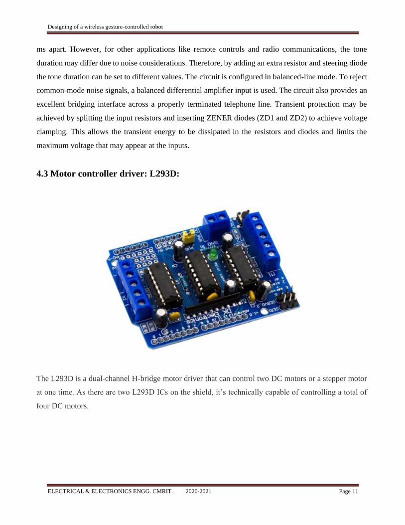
4.3 Motor controller driver: L293D:
The L293D is a dual-channel H-bridge motor driver that can control two DC motors or a stepper motor
at one time. As there are two L293D ICs on the shield, it’s technically capable of controlling a total of
four DC motors.
Designing of a wireless gesture-controlled robot
ELECTRICAL & ELECTRONICS ENGG. CMRIT. 2020-2021 Page 12
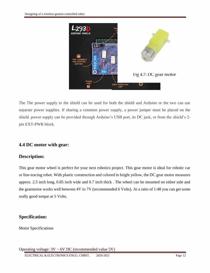
The The power supply to the shield can be used for both the shield and Arduino or the two can use
separate power supplies. If sharing a common power supply, a power jumper must be placed on the
shield. power supply can be provided through Arduino’s USB port, its DC jack, or from the shield’s 2-
pin EXT-PWR block.
4.4 DC motor with gear:
Description:
This gear motor wheel is perfect for your next robotics project. This gear motor is ideal for robotic car
or line-tracing robot. With plastic construction and colored in bright yellow, the DC gear motor measures
approx. 2.5 inch long, 0.85 inch wide and 0.7 inch thick . The wheel can be mounted on either side and
the gearmotor works well between 4V to 7V (recommended 6 Volts). At a ratio of 1:48 you can get some
really good torque at 5 Volts.
Specification:
Motor Specifications
Operating voltage: 3V ~ 6V DC (recommended value 5V)
Designing of a wireless gesture-controlled robot
ELECTRICAL & ELECTRONICS ENGG. CMRIT. 2020-2021 Page 13
Maximum torque: 800g.cm
Speed without load: 90±10rpm
Reduction ratio: 1:48
No Load current: 190mA(max.250mA)
Stall Current: ~1A
Strong anti-interference on this motor keeps it safe around micro-controllers.
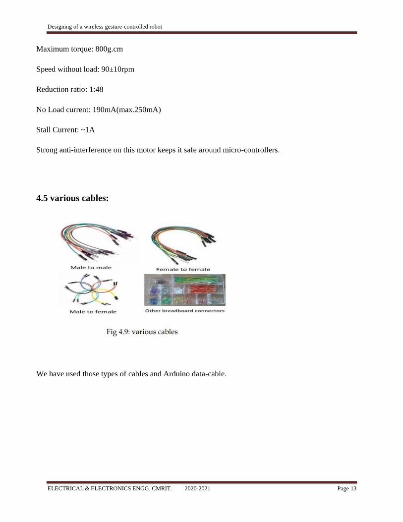
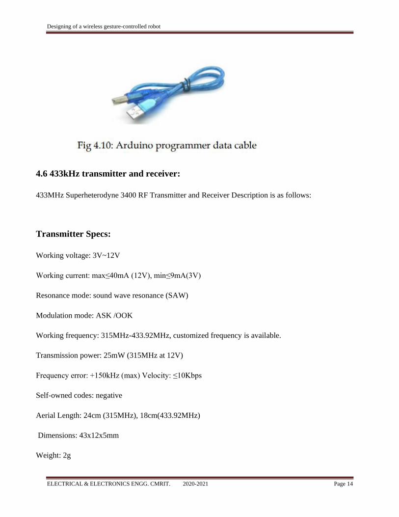
4.5 various cables:
We have used those types of cables and Arduino data-cable.
Designing of a wireless gesture-controlled robot
ELECTRICAL & ELECTRONICS ENGG. CMRIT. 2020-2021 Page 14
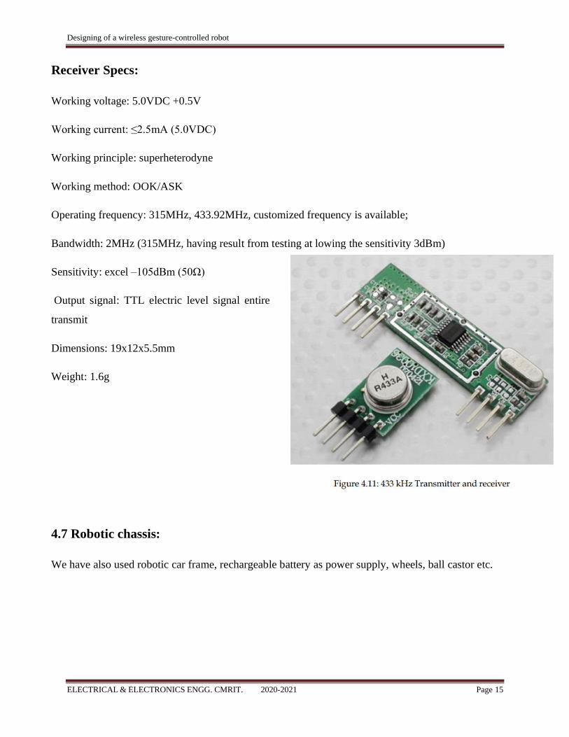
4.6 433kHz transmitter and receiver:
433MHz Superheterodyne 3400 RF Transmitter and Receiver Description is as follows:
Transmitter Specs:
Working voltage: 3V~12V
Working current: max≤40mA (12V), min≤9mA(3V)
Resonance mode: sound wave resonance (SAW)
Modulation mode: ASK /OOK
Working frequency: 315MHz-433.92MHz, customized frequency is available.
Transmission power: 25mW (315MHz at 12V)
Frequency error: +150kHz (max) Velocity: ≤10Kbps
Self-owned codes: negative
Aerial Length: 24cm (315MHz), 18cm(433.92MHz)
Dimensions: 43x12x5mm
Weight: 2g
Designing of a wireless gesture-controlled robot
ELECTRICAL & ELECTRONICS ENGG. CMRIT. 2020-2021 Page 15
Receiver Specs:
Working voltage: 5.0VDC +0.5V
Working current: ≤2.5mA (5.0VDC)
Working principle: superheterodyne
Working method: OOK/ASK
Operating frequency: 315MHz, 433.92MHz, customized frequency is available;
Bandwidth: 2MHz (315MHz, having result from testing at lowing the sensitivity 3dBm)
Sensitivity: excel –105dBm (50Ω)
Output signal: TTL electric level signal entire
transmit
Dimensions: 19x12x5.5mm
Weight: 1.6g
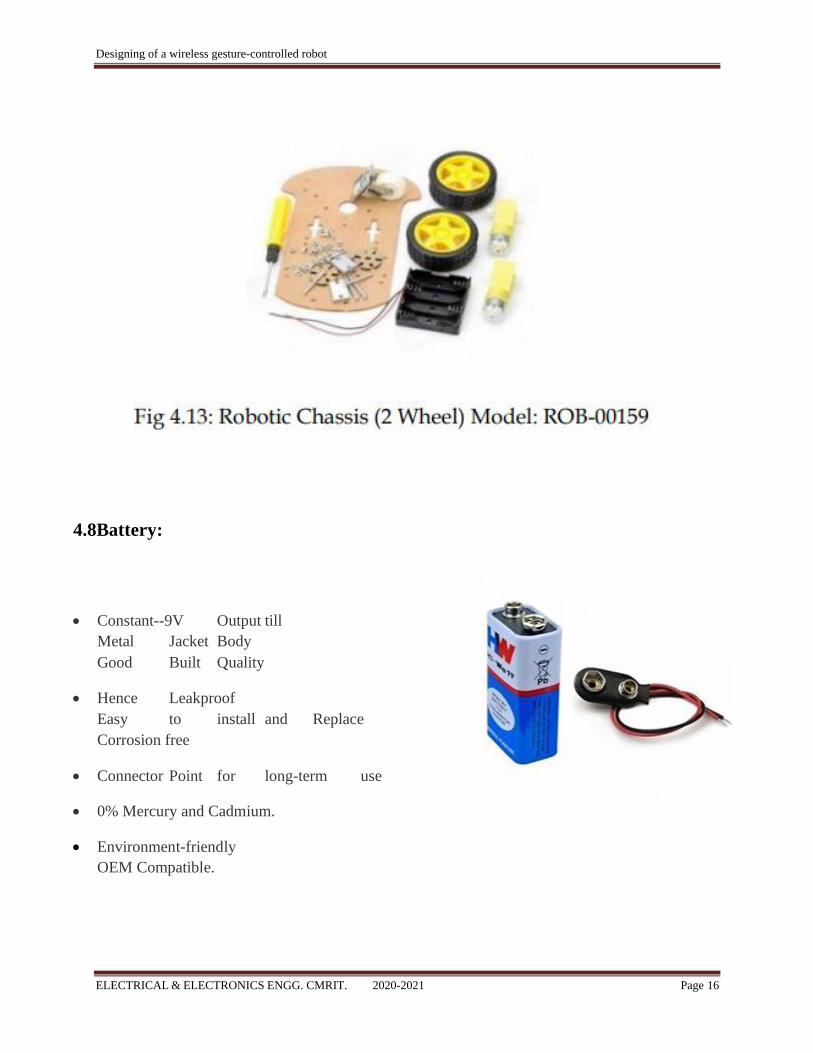
4.7 Robotic chassis:
We have also used robotic car frame, rechargeable battery as power supply, wheels, ball castor etc.
Designing of a wireless gesture-controlled robot
ELECTRICAL & ELECTRONICS ENGG. CMRIT. 2020-2021 Page 16
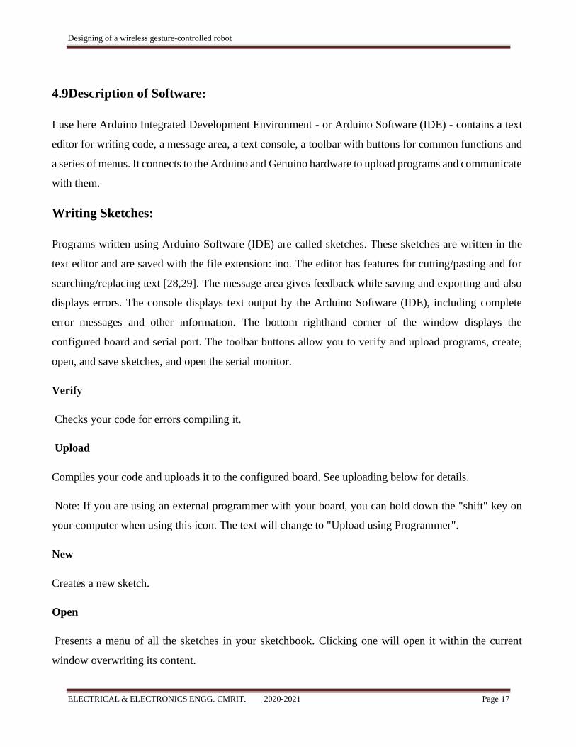
4.8Battery:
• Constant--9V Output till
Metal Jacket Body
Good Built Quality
• Hence Leakproof
Easy to install and Replace
Corrosion free
• Connector Point for long-term use
• 0% Mercury and Cadmium.
• Environment-friendly
OEM Compatible.
Designing of a wireless gesture-controlled robot
ELECTRICAL & ELECTRONICS ENGG. CMRIT. 2020-2021 Page 17
4.9Description of Software:
I use here Arduino Integrated Development Environment - or Arduino Software (IDE) - contains a text
editor for writing code, a message area, a text console, a toolbar with buttons for common functions and
a series of menus. It connects to the Arduino and Genuino hardware to upload programs and communicate
with them.
Writing Sketches:
Programs written using Arduino Software (IDE) are called sketches. These sketches are written in the
text editor and are saved with the file extension: ino. The editor has features for cutting/pasting and for
searching/replacing text [28,29]. The message area gives feedback while saving and exporting and also
displays errors. The console displays text output by the Arduino Software (IDE), including complete
error messages and other information. The bottom righthand corner of the window displays the
configured board and serial port. The toolbar buttons allow you to verify and upload programs, create,
open, and save sketches, and open the serial monitor.
Verify
Checks your code for errors compiling it.
Upload
Compiles your code and uploads it to the configured board. See uploading below for details.
Note: If you are using an external programmer with your board, you can hold down the "shift" key on
your computer when using this icon. The text will change to "Upload using Programmer".
New
Creates a new sketch.
Open
Presents a menu of all the sketches in your sketchbook. Clicking one will open it within the current
window overwriting its content.
Designing of a wireless gesture-controlled robot
ELECTRICAL & ELECTRONICS ENGG. CMRIT. 2020-2021 Page 18
Note: due to a bug in Java, this menu doesn't scroll; if you need to open a sketch late in the list, use the
File | Sketchbook menu instead.
Save
Saves your sketch.
Serial Monitor
Opens the serial monitor.
Additional commands are found within the five menus: File, Edit, Sketch, Tools, Help. The menus are
context sensitive, which means only those items relevant to the work currently being carried out are
available.
File
• New
Creates a new instance of the editor, with the bare minimum structure of a sketch already in place.
• Open
Allows to load a sketch file browsing through the computer drives and folders.
• Open Recent
Provides a short list of the most recent sketches, ready to be opened.
• Sketchbook
Shows the current sketches within the sketchbook folder structure; clicking on any name
opens the corresponding sketch in a new editor instance.
• Examples
Any example provided by the Arduino Software (IDE) or library shows up in this menu
Designing of a wireless gesture-controlled robot
ELECTRICAL & ELECTRONICS ENGG. CMRIT. 2020-2021 Page 19
item. All the examples are structured in a tree that allows easy access by topic or library.
• Close
Closes the instance of the Arduino Software from which it is clicked.
• Save
Saves the sketch with the current name. If the file hasn't been named before, a name will
be provided in a "Save as.." window.
• Save as...
Allows to save the current sketch with a different name.
• Page Setup
It shows the Page Setup window for printing.
Sends the current sketch to the printer according to the settings defined in Page Setup.
• Preferences
Opens the Preferences window where some settings of the IDE may be customized, as the
language of the IDE interface.
• Quit
Closes all IDE windows. The same sketches open when Quit was chosen will be automatically
reopened the next time you start the IDE.
Edit
• Undo/Redo
Goes back of one or more steps you did while editing; when you go back, you may go
forward with Redo.
• Cut
Designing of a wireless gesture-controlled robot
ELECTRICAL & ELECTRONICS ENGG. CMRIT. 2020-2021 Page 20
Removes the selected text from the editor and places it into the clipboard.
• Copy
Duplicates the selected text in the editor and places it into the clipboard.
• Copy for Forum
Copies the code of your sketch to the clipboard in a form suitable for posting to the forum,
complete with syntax coloring.
• Copy as HTML
Copies the code of your sketch to the clipboard as HTML, suitable for embedding in web
pages.
• Paste
Puts the contents of the clipboard at the cursor position, in the editor.
• Select All
Selects and highlights the whole content of the editor.
• Comment/Uncomment
Puts or removes the // comment marker at the beginning of each selected line.
• Increase/Decrease Indent
Adds or subtracts a space at the beginning of each selected line, moving the text one space
on the right or eliminating a space at the beginning.
• Find
Opens the Find and Replace window where you can specify text to search inside the
current sketch according to several options.
• Find Next
Highlights the next occurrence - if any - of the string specified as the search item in the
Designing of a wireless gesture-controlled robot
ELECTRICAL & ELECTRONICS ENGG. CMRIT. 2020-2021 Page 21
Find window, relative to the cursor position.
• Find Previous
Highlights the previous occurrence - if any - of the string specified as the search item in
the Find window relative to the cursor position.
Sketch
• Verify/Compile
Checks your sketch for errors compiling it; it will report memory usage for code and
variables in the console area.
• Upload
Compiles and loads the binary file onto the configured board through the configured Port.
• Upload Using Programmer
This will overwrite the bootloader on the board; you will need to use Tools > Burn
Bootloader to restore it and be able to Upload to USB serial port again. However, it allows you
to use the full capacity of the Flash memory for your sketch. Please note that this command will
NOT burn the fuses. To do so a Tools -> Burn Bootloader command must be executed.
• Export Compiled Binary
Saves a .hex file that may be kept as archive or sent to the board using other tools.
• Show Sketch Folder
Opens the current sketch folder.
• Include Library
Adds a library to your sketch by inserting #include statements at the start of your code.
For more details, see libraries below. Additionally, from this menu item you can access the
Library Manager and import new libraries from .zip files.
• Add File...

Designing of a wireless gesture-controlled robot
ELECTRICAL & ELECTRONICS ENGG. CMRIT. 2020-2021 Page 22
Adds a source file to the sketch (it will be copied from its current location). The new file
appears in a new tab in the sketch window. Files can be removed from the sketch using the tab
menu accessible clicking on the small triangle icon below the serial monitor one on the right side
o the toolbar.
Tools
• Auto Format
This formats your code nicely: i.e. indents it so that opening and closing curly braces line
up, and that the statements inside curly braces are indented more.
• Archive Sketch
Archives a copy of the current sketch in .zip format. The archive is placed in the same
directory as the sketch.
• Fix Encoding & Reload
Fixes possible discrepancies between the editor char map encoding and other operating
systems char maps.
• Serial Monitor
Opens the serial monitor window and initiates the exchange of data with any connected
board on the currently selected Port. This usually resets the board, if the board supports Reset
over serial port opening.
• Board
Select the board that you're using. See below for descriptions of the various boards.
• Port
This menu contains all the serial devices (real or virtual) on your machine. It should
automatically refresh every time you open the top-level tools menu.
• Programmer
For selecting a harware programmer when programming a board or chip and not using the
Designing of a wireless gesture-controlled robot
ELECTRICAL & ELECTRONICS ENGG. CMRIT. 2020-2021 Page 23
onboard USB-serial connection. Normally you won't need this, but if you're burning a bootloader
to a new microcontroller, you will use this.
• Burn Bootloader
The items in this menu allow you to burn a bootloader onto the microcontroller on an
Arduino board. This is not required for normal use of an Arduino or Genuino board but is useful
if you purchase a new ATmega microcontroller (which normally come without a bootloader).
Ensure that you've selected the correct board from the Boards menu before burning the bootloader
on the target board. This command also set the right fuses.
Help
Here you find easy access to a number of documents that come with the Arduino Software (IDE).
You have access to Getting Started, Reference, this guide to the IDE and other documents locally, without
an internet connection. The documents are a local copy of the online ones and may link back to our online
website.
Sketchbook
The Arduino Software (IDE) uses the concept of a sketchbook: a standard place to store your
programs (or sketches). The sketches in your sketchbook can be opened from the File > Sketchbook
menu or from the Open button on the toolbar. The first time you run the Arduino software, it will
automatically create a directory for your sketchbook. You can view or change the location of the
sketchbook location from with the Preferences dialog. Beginning with version 1.0, files are saved with a
.ino file extension. Previous versions use the .pde extension. You may still open .pde named files in
version 1.0 and later, the software will automatically rename the extension to .ino.
Tabs, Multiple Files, and Compilation
Allows you to manage sketches with more than one file (each of which appears in its own tab).
These can be normal Arduino code files (no visible extension), C files (.c extension), C++ files (.cpp), or
header files (.h).
Designing of a wireless gesture-controlled robot
ELECTRICAL & ELECTRONICS ENGG. CMRIT. 2020-2021 Page 24
Uploading
Before uploading your sketch, you need to select the correct items from the Tools > Board and
Tools > Port menus. The boards are described below. On the Mac, the serial port is probably something
like /dev/tty.usbmodem241 (for an Uno or Mega2560 or Leonardo) or /dev/tty.usbserial-1B1 (for a
Duemilanove or earlier USB board), or /dev/tty.USA19QW1b1P1.1 (for a serial board connected with a
Keyspan USB-to-Serial adapter). On Windows, it's probably COM1 or COM2 (for a serial board) or
COM4, COM5, COM7, or higher (for a USB board) - to find out, you look for USB serial device in the
ports section of the Windows Device Manager. On Linux, it should be /dev/ttyACMx , /dev/ttyUSBx or
similar. Once you've selected the correct serial port and board, press the upload button in the toolbar or
select the Upload item from the File menu. Current Arduino boards will reset automatically and begin
the upload. With older boards (preDiecimila) that lack auto-reset, you'll need to press the reset button on
the board just Page 46 of 60 before starting the upload. On most boards, you'll see the RX and TX LEDs
blink as the sketch is uploaded. The Arduino Software (IDE) will display a message when the upload is
complete, or show an error. When you upload a sketch, you're using the Arduino bootloader, a small
program that has been loaded on to the microcontroller on your board. It allows you to upload code
without using any additional hardware. The bootloader is active for a few seconds when the board resets;
then it starts whichever sketch was most recently uploaded to the microcontroller. The bootloader will
blink the on-board (pin 13) LED when it starts (i.e. when the board resets).
Libraries
Libraries provide extra functionality for use in sketches, e.g. working with hardware or
manipulating data. To use a library in a sketch, select it from the Sketch > Import Library menu. This
will insert one or more #include statements at the top of the sketch and compile the library with your
sketch. Because libraries are uploaded to the board with your sketch, they increase the amount of space
it takes up. If a sketch no longer needs a library, simply delete its #include statements from the top of
your code. There is a list of libraries in the reference. Some libraries are included with the Arduino
software. Others can be downloaded from a variety of sources or through the Library Manager. Starting
with version 1.0.5 of the IDE, you do can import a library from a zip file and use it in an open sketch.
See these instructions for installing a third-party library. To write your own library, see this tutorial.
Designing of a wireless gesture-controlled robot
ELECTRICAL & ELECTRONICS ENGG. CMRIT. 2020-2021 Page 25
Boards
The board selection has two effects: it sets the parameters (e.g. CPU speed and baud rate) used
when compiling and uploading sketches; and sets and the file and fuse settings used by the burn
bootloader command. Some of the board definitions differ only in the latter, so even if you've been
uploading successfully with a particular selection you'll want to check it before burning the bootloader.
You can find a comparison table between the various boards here.
Arduino Software (IDE) includes the built in support for the boards in the following list, all based
on the AVR Core. The Boards Manager included in the standard installation allows to add support for
the growing number of new boards based on different cores like Arduino Due, Arduino Zero, Edison,
Galileo and so on.
• Arduino Yùn
An ATmega32u4 running at 16 MHz with auto-reset, 12 Analog In, 20 Digital I/O and 7 PWM.
• Arduino/Genuino Uno
An ATmega328 running at 16 MHz with auto-reset, 6 Analog In, 14 Digital I/O and 6 PWM
• Arduino Diecimila or Duemilanove w/ ATmega168 An ATmega168 running at 16 MHz with auto-
reset.
• Arduino Nano w/ ATmega328
An ATmega328 running at 16 MHz with auto-reset. Has eight analog inputs.
• Arduino/Genuino Mega 2560
An ATmega2560 running at 16 MHz with auto-reset, 16 Analog In, 54 Digital I/O and 15 PWM.
• Arduino Mega

Designing of a wireless gesture-controlled robot
ELECTRICAL & ELECTRONICS ENGG. CMRIT. 2020-2021 Page 26
An ATmega1280 running at 16 MHz with auto-reset, 16 Analog In, 54 Digital I/O and 15 PWM.
• Arduino Mega ADK
An ATmega2560 running at 16 MHz with auto-reset, 16 Analog In, 54 Digital I/O and 15 PWM.
• Arduino Leonardo
An ATmega32u4 running at 16 MHz with auto-reset, 12 Analog In, 20 Digital I/O and 7 PWM.
• Arduino Micro
An ATmega32u4 running at 16 MHz with auto-reset, 12 Analog In, 20 Digital I/O and 7 PWM.
• Arduino Esplora
An ATmega32u4 running at 16 MHz with auto-reset.
• Arduino Mini w/ ATmega328
An ATmega328 running at 16 MHz with auto-reset, 8 Analog In, 14 Digital I/O and 6 PWM.
• Arduino Ethernet
Equivalent to Arduino UNO with an Ethernet shield: An ATmega328 running at 16 MHz with
auto-reset, 6 Analog In, 14 Digital I/O and 6 PWM.
• Arduino Fio
An ATmega328 running at 8 MHz with auto-reset. Equivalent to Arduino Pro or Pro Mini (3.3V,
8 MHz) w/ ATmega328, 6 Analog In, 14 Digital I/O and 6 PWM.
• Arduino BT w/
ATmega328 ATmega328 running at 16 MHz. The bootloader burned (4 KB) includes codes to
initialize the on-board bluetooth module, 6 Analog In, 14 Digital I/O and 6 PWM..
• LilyPad Arduino USB
Designing of a wireless gesture-controlled robot
ELECTRICAL & ELECTRONICS ENGG. CMRIT. 2020-2021 Page 27
An ATmega32u4 running at 8 MHz with auto-reset, 4 Analog In, 9 Digital I/O and 4 PWM.
• LilyPad Arduino
An ATmega168 or ATmega132 running at 8 MHz with auto-reset, 6 Analog In, 14 Digital I/O
and 6 PWM.
• Arduino Pro or Pro Mini (5V, 16 MHz) w/
ATmega328 An ATmega328 running at 16 MHz with auto-reset. Equivalent to Arduino
Duemilanove or Nano w/ ATmega328; 6 Analog In, 14 Digital I/O and 6 PWM.
• Arduino NG or older w/ ATmega168
An ATmega168 running at 16 MHz without auto-reset. Compilation and upload is equivalent to
Arduino Diecimila or Duemilanove w/ ATmega168, but the bootloader burned has a slower timeout (and
blinks the pin 13 LED three times on reset); 6 Analog In, 14 Digital I/O and 6 PWM.
• Arduino Robot Control
An ATmega328 running at 16 MHz with auto-reset.
• Arduino Robot Motor
An ATmega328 running at 16 MHz with auto-reset.
• Arduino Gemma
An ATtiny85 running at 8 MHz with auto-reset, 1 Analog In, 3 Digital I/O and 2 PWM.
Designing of a wireless gesture-controlled robot
ELECTRICAL & ELECTRONICS ENGG. CMRIT. 2020-2021 Page 28
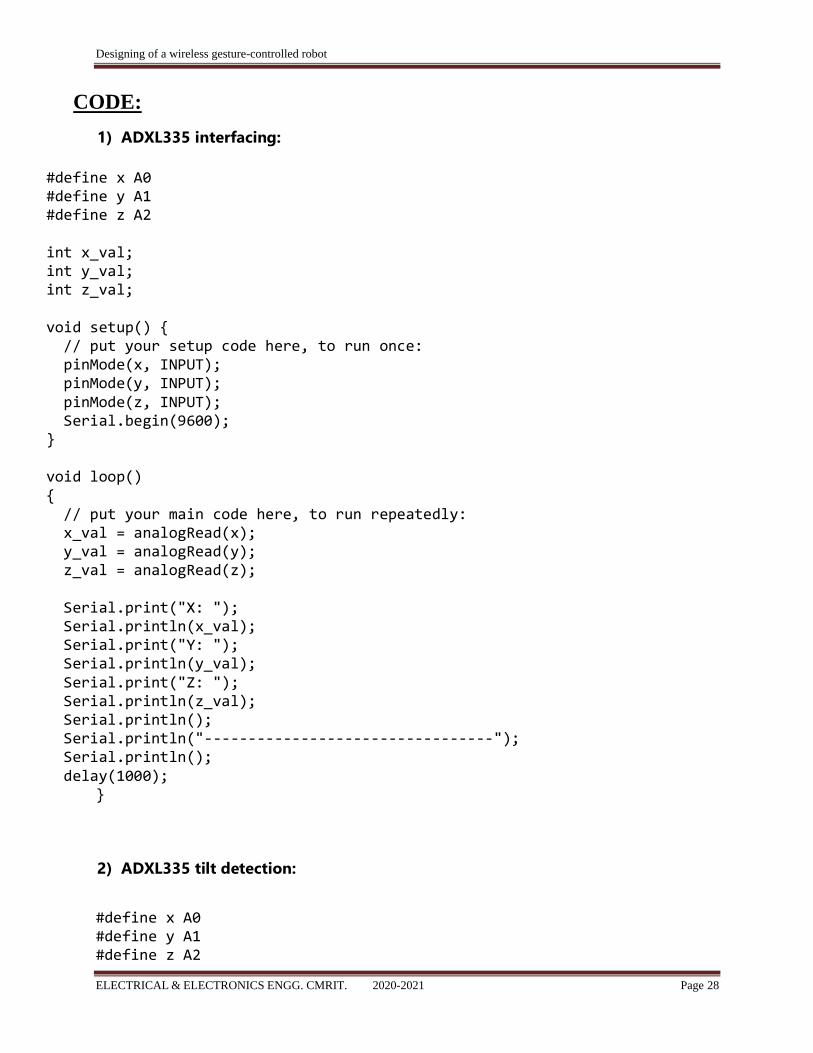
CODE:
1) ADXL335 interfacing:
#define x A0 #define y A1 #define z A2 int x_val; int y_val; int z_val; void setup() { // put your setup code here, to run once: pinMode(x, INPUT); pinMode(y, INPUT); pinMode(z, INPUT); Serial.begin(9600); } void loop() { // put your main code here, to run repeatedly: x_val = analogRead(x); y_val = analogRead(y); z_val = analogRead(z); Serial.print("X: "); Serial.println(x_val); Serial.print("Y: "); Serial.println(y_val); Serial.print("Z: "); Serial.println(z_val); Serial.println(); Serial.println("---------------------------------"); Serial.println(); delay(1000);
}
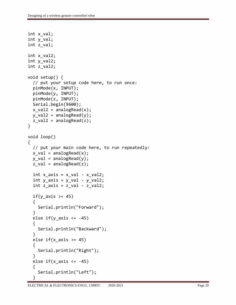
2) ADXL335 tilt detection:
#define x A0 #define y A1 #define z A2
Designing of a wireless gesture-controlled robot
ELECTRICAL & ELECTRONICS ENGG. CMRIT. 2020-2021 Page 29
int x_val; int y_val; int z_val; int x_val2; int y_val2; int z_val2; void setup() { // put your setup code here, to run once: pinMode(x, INPUT); pinMode(y, INPUT); pinMode(z, INPUT); Serial.begin(9600); x_val2 = analogRead(x); y_val2 = analogRead(y); z_val2 = analogRead(z); } void loop() { // put your main code here, to run repeatedly: x_val = analogRead(x); y_val = analogRead(y); z_val = analogRead(z); int x_axis = x_val - x_val2; int y_axis = y_val - y_val2; int z_axis = z_val - z_val2; if(y_axis >= 45) { Serial.println("Forward"); } else if(y_axis <= -45) { Serial.println("Backward"); } else if(x_axis >= 45) { Serial.println("Right"); } else if(x_axis <= -45) { Serial.println("Left"); }
Designing of a wireless gesture-controlled robot
ELECTRICAL & ELECTRONICS ENGG. CMRIT. 2020-2021 Page 30
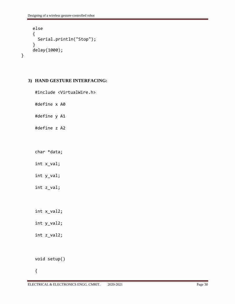
else { Serial.println("Stop"); } delay(1000);
}
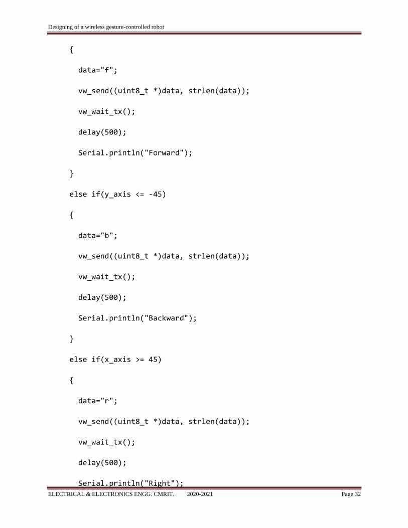
3) HAND GESTURE INTERFACING:
#include <VirtualWire.h>
#define x A0
#define y A1
#define z A2
char *data;
int x_val;
int y_val;
int z_val;
int x_val2;
int y_val2;
int z_val2;
void setup()
{
Designing of a wireless gesture-controlled robot
ELECTRICAL & ELECTRONICS ENGG. CMRIT. 2020-2021 Page 31
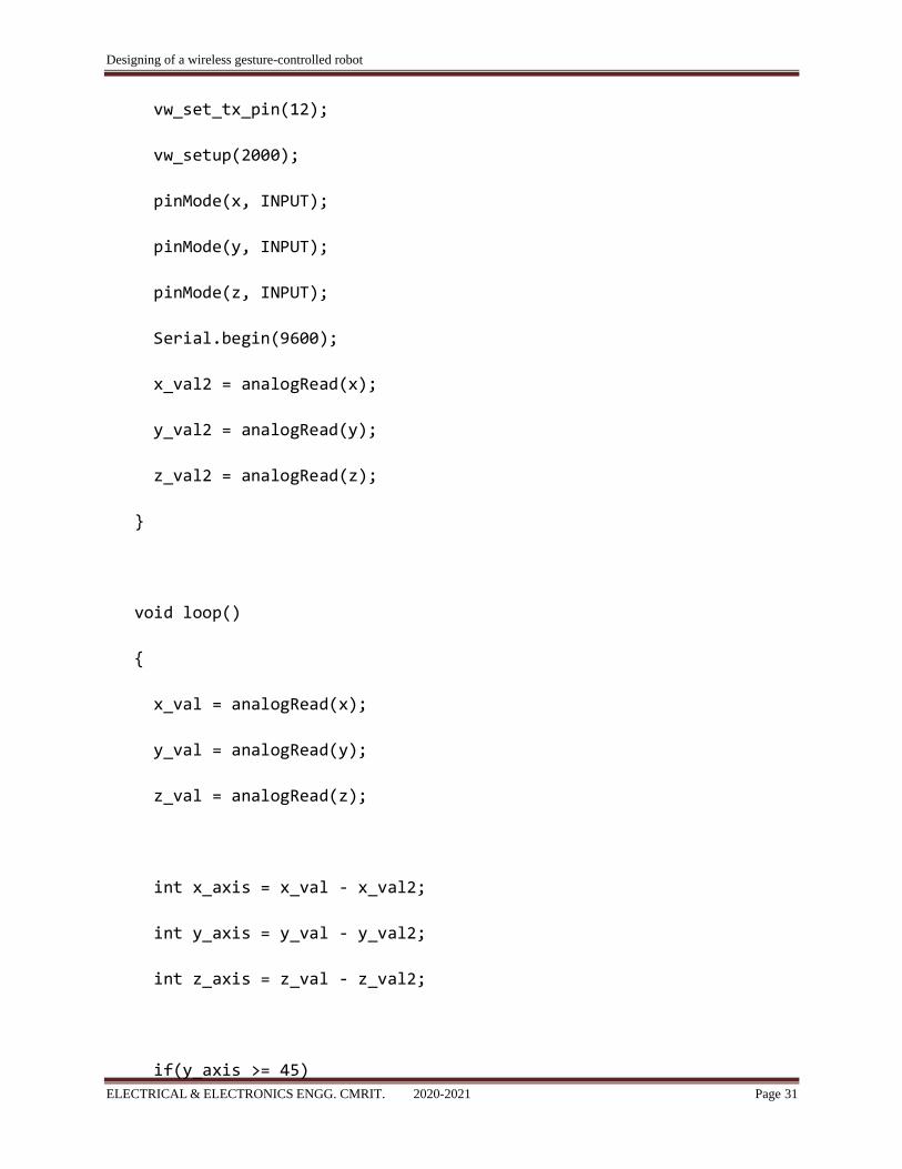
vw_set_tx_pin(12);
vw_setup(2000);
pinMode(x, INPUT);
pinMode(y, INPUT);
pinMode(z, INPUT);
Serial.begin(9600);
x_val2 = analogRead(x);
y_val2 = analogRead(y);
z_val2 = analogRead(z);
}
void loop()
{
x_val = analogRead(x);
y_val = analogRead(y);
z_val = analogRead(z);
int x_axis = x_val - x_val2;
int y_axis = y_val - y_val2;
int z_axis = z_val - z_val2;
if(y_axis >= 45)
Designing of a wireless gesture-controlled robot
ELECTRICAL & ELECTRONICS ENGG. CMRIT. 2020-2021 Page 32
{
data="f";
vw_send((uint8_t *)data, strlen(data));
vw_wait_tx();
delay(500);
Serial.println("Forward");
}
else if(y_axis <= -45)
{
data="b";
vw_send((uint8_t *)data, strlen(data));
vw_wait_tx();
delay(500);
Serial.println("Backward");
}
else if(x_axis >= 45)
{
data="r";
vw_send((uint8_t *)data, strlen(data));
vw_wait_tx();
delay(500);
Serial.println("Right");
Designing of a wireless gesture-controlled robot
ELECTRICAL & ELECTRONICS ENGG. CMRIT. 2020-2021 Page 33
}
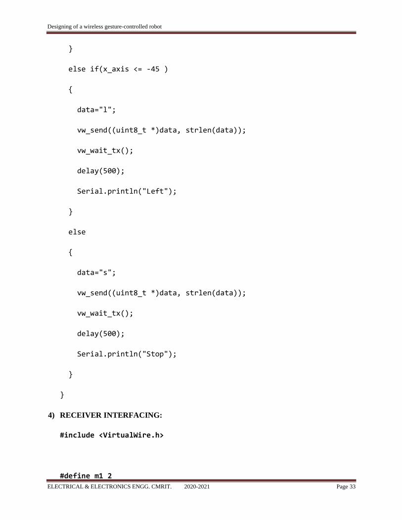
else if(x_axis <= -45 )
{
data="l";
vw_send((uint8_t *)data, strlen(data));
vw_wait_tx();
delay(500);
Serial.println("Left");
}
else
{
data="s";
vw_send((uint8_t *)data, strlen(data));
vw_wait_tx();
delay(500);
Serial.println("Stop");
}
}
4) RECEIVER INTERFACING:
#include <VirtualWire.h>
#define m1 2
Designing of a wireless gesture-controlled robot
ELECTRICAL & ELECTRONICS ENGG. CMRIT. 2020-2021 Page 34
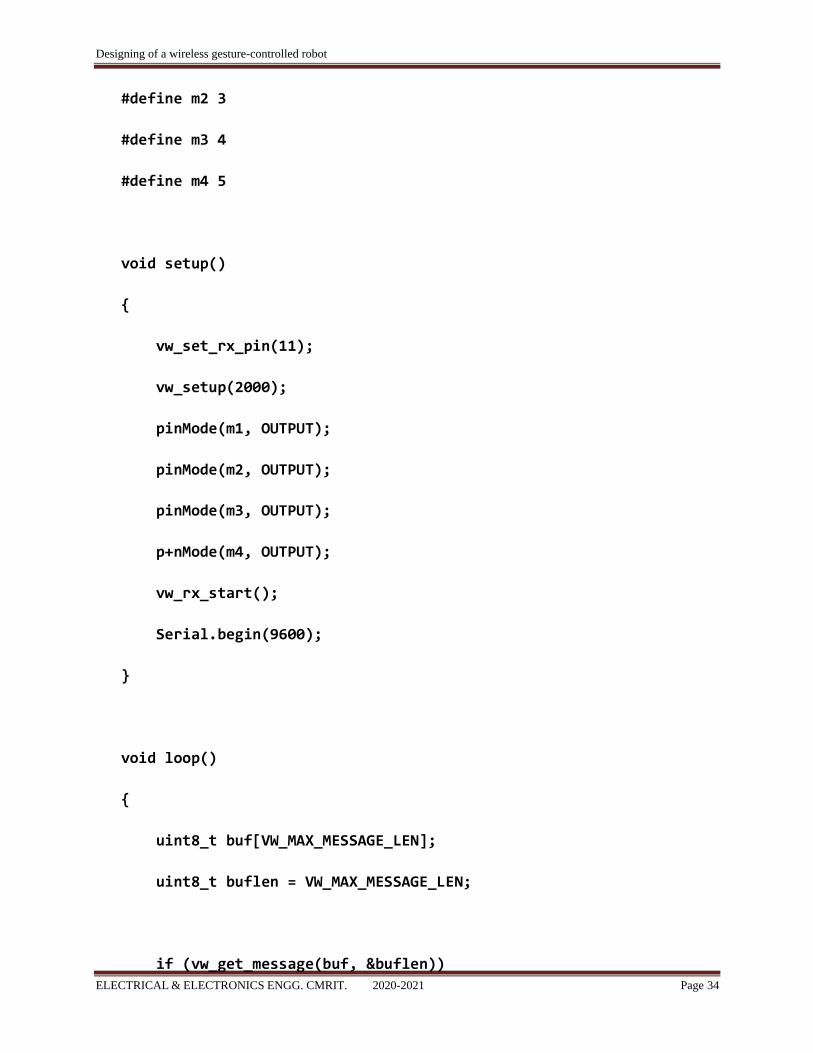
#define m2 3
#define m3 4
#define m4 5
void setup()
{
vw_set_rx_pin(11);
vw_setup(2000);
pinMode(m1, OUTPUT);
pinMode(m2, OUTPUT);
pinMode(m3, OUTPUT);
p+nMode(m4, OUTPUT);
vw_rx_start();
Serial.begin(9600);
}
void loop()
{
uint8_t buf[VW_MAX_MESSAGE_LEN];
uint8_t buflen = VW_MAX_MESSAGE_LEN;
if (vw_get_message(buf, &buflen))

Designing of a wireless gesture-controlled robot
ELECTRICAL & ELECTRONICS ENGG. CMRIT. 2020-2021 Page 35
{
if(buf[0]=='f')
{
digitalWrite(m1,HIGH);
digitalWrite(m2,LOW);
digitalWrite(m3,HIGH);
digitalWrite(m4,LOW);
Serial.println("Forward");
}
else if(buf[0]=='b')
{
digitalWrite(m1,LOW);
digitalWrite(m2,HIGH);
digitalWrite(m3,LOW);
digitalWrite(m4,HIGH);
Serial.println("Backward");
}
else if(buf[0]=='r')
{
digitalWrite(m1,HIGH);
digitalWrite(m2,LOW);
digitalWrite(m3,LOW);
Designing of a wireless gesture-controlled robot
ELECTRICAL & ELECTRONICS ENGG. CMRIT. 2020-2021 Page 36
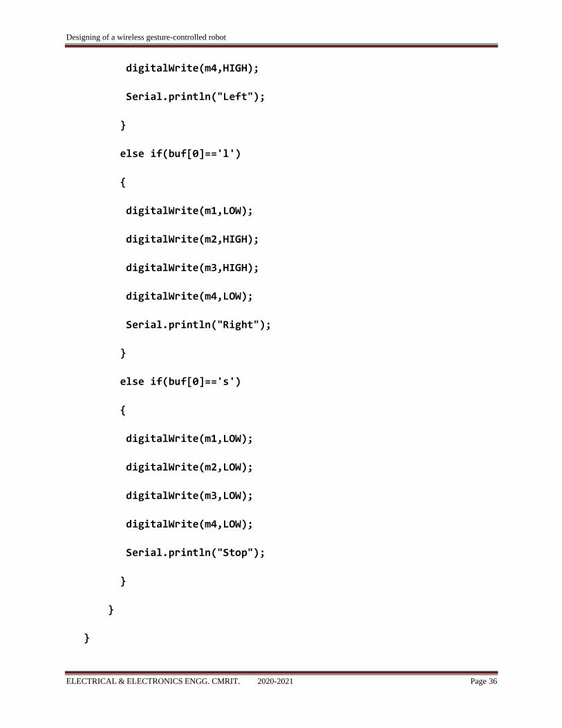
digitalWrite(m4,HIGH);
Serial.println("Left");
}
else if(buf[0]=='l')
{
digitalWrite(m1,LOW);
digitalWrite(m2,HIGH);
digitalWrite(m3,HIGH);
digitalWrite(m4,LOW);
Serial.println("Right");
}
else if(buf[0]=='s')
{
digitalWrite(m1,LOW);
digitalWrite(m2,LOW);
digitalWrite(m3,LOW);
digitalWrite(m4,LOW);
Serial.println("Stop");
}
}
}
Designing of a wireless gesture-controlled robot
ELECTRICAL & ELECTRONICS ENGG. CMRIT. 2020-2021 Page 37
CHAPTER 5
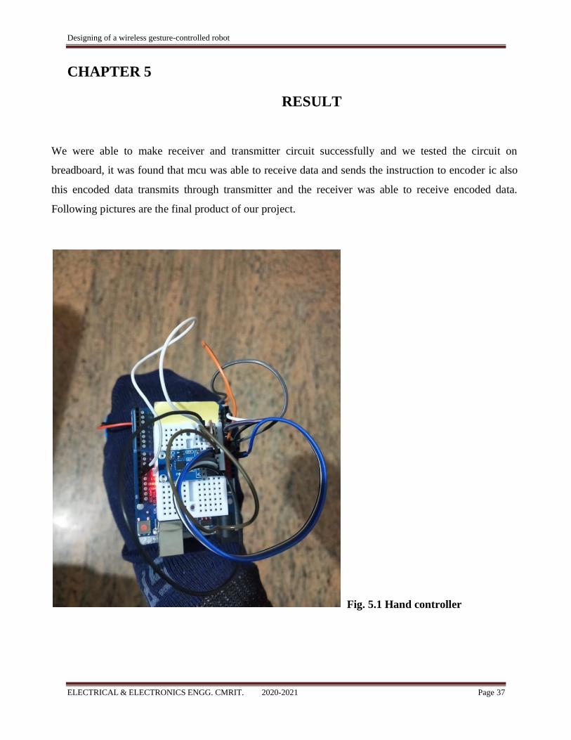
RESULT
We were able to make receiver and transmitter circuit successfully and we tested the circuit on
breadboard, it was found that mcu was able to receive data and sends the instruction to encoder ic also
this encoded data transmits through transmitter and the receiver was able to receive encoded data.
Following pictures are the final product of our project.
Fig. 5.1 Hand controller

Designing of a wireless gesture-controlled robot
ELECTRICAL & ELECTRONICS ENGG. CMRIT. 2020-2021 Page 38
Fig 5.1. Portrait view of car

Designing of a wireless gesture-controlled robot
ELECTRICAL & ELECTRONICS ENGG. CMRIT. 2020-2021 Page 39
Fig 5.2. Top view of car
Designing of a wireless gesture-controlled robot
ELECTRICAL & ELECTRONICS ENGG. CMRIT. 2020-2021 Page 40
CHAPTER-6
CONCLUSION
The purpose of project is to control a toy car using accelerometer sensors attached to a hand glove. The
sensors are intended to replace the remote control that is generally used to run the car. It will allow us to
control the forward and backward, and left and right movements, while using the same accelerometer sensor
to control the throttle of the car. based on the hand movements. By using the above mentioned components
the hardware was setup, thus resulting in the formation of a robot. In order to implement the experiment a
Dell laptop was used, whose web camera acted as the input device for capturing the video. The software
part was developed in Java for image processing wherein the hand gestures were analyzed to extract the
actual direction. Eclipse Ide was used for developing the java code. The direction thus identified was send
as characters to the robot with the help of Zigbee. XBee S2 version of Zigbee was used for enabling the
communication. The final movement of the robot can be concluded as follows: At the beginning the robot
was in a stop mode. As the hand moved from bottom to top, the robot moved in the forward direction. As
the hand moved from top to bottom, the robot moved in the backward direction. As the hand was shown as
an acute angle towards the left, the robot moved towards the left direction. As the hand was shown as an
acute angle towards the right, the robot moved towards the right direction. As the hand is kept stationary
with respect to the environment, the robot was in the stop mode. From the experiment, about 80% of the
implementation worked according; the remaining was less due to background interference which is a
negative marking to the implementation. Hand Gesture Controlled Robot System gives a more natural way
of controlling devices. The command for the robot to navigate in specific direction in the environment is
based on technique of hand gestures provided by the user. Without using any external hardware support for
gesture input unlike specified existing system, user can control a robot from his software station.
Designing of a wireless gesture-controlled robot
ELECTRICAL & ELECTRONICS ENGG. CMRIT. 2020-2021 Page 41
REFERENCES
1. Khan, R.Z. and Ibraheem, N.A., 2012. Hand gesture recognition: a literature
review. International journal of artificial Intelligence & Applications, 3(4), p.161.
2. J. P. Wachs, M. Kölsch, H. Stern, and Y. Edan, "Vision-based hand-gesture
applications," Communications of the ACM, vol. 54, pp. 60-71, 2011.
3. S. Mitra and T. Acharya, "Gesture Recognition: A Survey," Systems, Man, and
Cybernetics, Part C: Applications and Reviews, vol. 37, pp. 311-324, 2007.
4. A. Erol, G. Bebis, M. Nicolescu, R. D. Boyle, and X. Twombly, "Vision-based
hand pose estimation: A review," Computer Vision and Image Understanding, vol.
108, pp. 52-73, 2007
5. Fakhreddine Karray, Milad Alemzadeh, Jamil Abou Saleh, Mo Nours Arab,
(2008) .“HumanComputer Interaction: Overview on State of the Art”, International
Journal on Smart Sensing and Intelligent Systems, Vol. 1(1).
6. Wikipedia Website.
7. Mokhtar M. Hasan, Pramoud K. Misra, (2011). “Brightness Factor Matching
For Gesture Recognition System Using Scaled Normalization”, International
Journal of Computer Science & Information Technology (IJCSIT), Vol. 3(2).
8. Xingyan Li. (2003). “Gesture Recognition Based on Fuzzy C-Means Clustering
Algorithm”, Department of Computer Science. The University of Tennessee
Knoxville.
9. S. Mitra, and T. Acharya. (2007). “Gesture Recognition: A Survey” IEEE
Transactions on systems, Man and Cybernetics, Part C: Applications andreviews,
vol. 37 (3), pp. 311- 324, doi: 10.1109/TSMCC.2007.893280.
10. Simei G. Wysoski, Marcus V. Lamar, Susumu Kuroyanagi, Akira Iwata,
Designing of a wireless gesture-controlled robot
ELECTRICAL & ELECTRONICS ENGG. CMRIT. 2020-2021 Page 42
(2002). “A Rotation Invariant Approach On Static-Gesture Recognition Using
Boundary Histograms And Neural Networks,” IEEE Proceedings of the 9th
International Conference on Neural Information Processing, Singapura.
11. Joseph J. LaViola Jr., (1999). “A Survey of Hand Posture and Gesture
Recognition Techniques and Technology”, Master Thesis, Science and
Technology Center for Computer Graphics and Scientific Visualization, USA.
12. Rafiqul Z. Khan, Noor A. Ibraheem, (2012). “Survey on Gesture Recognition
for Hand Image Postures”, International Journal of Computer And Information
Science, Vol. 5(3), Doi: 10.5539/cis.v5n3p110
13. Thomas B. Moeslund and Erik Granum, (2001). “A Survey of Computer
VisionBased Human Motion Capture,” Elsevier, Computer Vision and Image
Understanding, Vol. 81, pp. 231–268.
14. N. Ibraheem, M. Hasan, R. Khan, P. Mishra, (2012). “comparative study of
skin color base segmentation techniques”, Aligarh Muslim University, A.M.U.,
Aligarh, India.
15. Mahmoud E., Ayoub A., J¨org A., and Bernd M., (2008). “Hidden Markov
ModelBased Isolated and Meaningful Hand Gesture Recognition”, World
Academy of Science, Engineering and Technology 41.
16. E. Stergiopoulou, N. Papamarkos. (2009). “Hand gesture recognition using a
neural network shape fitting technique,” Elsevier Engineering Applications of
Artificial Intelligence, vol. 22(8), pp. 1141–1158, doi:
10.1016/j.engappai.2009.03.008