GESTURE CONTROL INTERFACE OF A ROBOT-CAR USING ...
49
GESTURE CONTROL INTERFACE OF A ROBOT-CAR USING RASPBERRY PI By AFREEN BANO(AEIE2015/042) MITUN KUNDU(AEIE2015/033) AYAN JANA(AEIE2015/028) SUMAN KUMAR PAL(AEIE2015/013) Under Supervision of MR. ARIJIT GHOSH Project report submitted in partial fulfillment for the Degree of B. Tech in Applied Electronics & Instrumentation Engineering under Maulana Abul Kalam Azad University of Technology DEPARTMENT OF APPLIED ELECTRONICS & INSTRUMENTATION ENGINEERING, RCC INSTITUTE OF INFORMATION TECHNOLOGY, CANAL SOUTH ROAD, BELIAGHATA, KOLKATA – 700015, May, 2019
-
Upload
khangminh22 -
Category
Documents
-
view
0 -
download
0
Transcript of GESTURE CONTROL INTERFACE OF A ROBOT-CAR USING ...
GESTURE CONTROL INTERFACE OF A ROBOT-CAR
USING RASPBERRY PI
By
AFREEN BANO(AEIE2015/042)
MITUN KUNDU(AEIE2015/033)
AYAN JANA(AEIE2015/028)
SUMAN KUMAR PAL(AEIE2015/013)
Under Supervision of
MR. ARIJIT GHOSH
Project report submitted in partial fulfillment for
the Degree of B. Tech in Applied Electronics &
Instrumentation Engineering under Maulana Abul
Kalam Azad University of Technology
DEPARTMENT OF APPLIED ELECTRONICS &
INSTRUMENTATION ENGINEERING,
RCC INSTITUTE OF INFORMATION TECHNOLOGY,
CANAL SOUTH ROAD, BELIAGHATA, KOLKATA – 700015,
May, 2019
ACKNOWLEDGEMENT
It is a great privilege for us to express our profound gratitude to our respected teacher Mr. Arijit
Ghosh, Head of the Department, Applied Electronics &Instrumentation Engineering, RCC
Institute of Information Technology, for permitting us to pursue the project, for his constant
guidance, valuable suggestions, supervision and inspiration throughout the course work without
which it would have been difficult to complete the work within scheduled time.
We would like to express our gratitude towards Miss Naiwrita Dey for her kind co-
operation and encouragement which helped us in completion of this project.
We would like to take this opportunity to thank all the respected teachers of this department for
being a perennial source of inspiration and showing the right path at the time of necessity.
_______________________
AFREEN BANO
(11705515003)
_______________________
MITUN KUNDU
(11705515026)
_______________________
AYAN JANA
(11705515009)
_______________________
SUMAN KUMAR PAL
(11705515048)
RCC INSTITUTE OF INFORMATION TECHNOLOGY CANAL SOUTH ROAD, BELIAGHATA, KOLKATA – 700 015 PHONE : 2323 2463 FAX : (033)2323 4668
E-mail : [email protected] Website : www.rcciit.org
CERTIFICATE OF APPROVAL
The project report titled “Gesture Control Interface of a Robot-Car using Raspberry Pi”
prepared by Afreen Bano, AEIE2015/042, Mitun Kundu, AEIE2015/033, Ayan Jana,
AEIE2015/028 and Suman Kumar Pal, AEIE2015/013 is hereby approved and certified as a
creditable study in technological subjects performed in a way sufficient for its acceptance for
partial fulfilment of the degree for which it is submitted.
It is to be understood that by this approval, the undersigned do not, necessarily endorse or
approve any statement made, opinion expressed or conclusion drawn therein, but approve the
project only for the purpose for which it is submitted.
-----------------------------------
Mr. ARIJIT GHOSH
Applied Electronics & Instrumentation
Engineering
------------------------------------
Mr. ARIJIT GHOSH
Applied Electronics & Instrumentation
Engineering
--------------------------------------
Examiner
--------------------------------------
Examiner
RCC INSTITUTE OF INFORMATION TECHNOLOGY CANAL SOUTH ROAD, BELIAGHATA, KOLKATA – 700 015 PHONE : 2323 2463 FAX : (033)2323 4668
E-mail : [email protected] Website : www.rcciit.org
RECOMMENDATION
I hereby recommend that the project report titled “Gesture Control Interface of Robot-Car
using Raspberry Pi” prepared by Afreen Bano, AEIE2015/042, Mitun Kundu,
AEIE2015/033, Ayan Jana, AEIE2015/028 and Suman Kumar Pal, AEIE2015/013 be
accepted in partial fulfillment of the requirement for the Degree of Bachelor of Technology in
Applied Electronics &Instrumentation Engineering, RCC Institute of Information Technology.
-------------------------------------
Mr. ARIJIT GHOSH
--------------------------------------
Mr. ARIJIT GHOSH
Applied Electronics & Instrumentation Engineering
ABSTRACT
The integration of more and more functionality into the human machine interface (HMI) of
vehicles increases the complexity of device handling. Thus optimal use of different human
sensory channels is an approach to simplify the interaction with in-car devices. Using this idea, a
car-robot can be implemented whose navigation can be done wirelessly with the help of a
Raspberry Pi.
Robots are currently playing a big role in our lives. There are different type of robots: wheeled
robots, flying robots, factory building robots. The current way to control this robots are by using
a keyboard, joystick or pre-programmed commands. This project is about to introduce a new way
to control a robot and it is by using gestures. This project is to build a remote control robot(car),
which is controlled from a distance using only gestures.
The project has two components a car and a control station. The control station is computer
which has gesture recognition hardware so that it can detect the commands and send them to the
car. The control station is the micro computer Raspberry Pi 3B. The data from the hand
movements with the help of the accelerometer are fed into the Encoder HT 12E through the
Raspberry Pi. Then the values are transmitted with the help of Tx 434. Rx 434 receives the
values in the receiver part, where it is decoded by a Decoder HT 12D and sent to the motor driver
L293D. Thus motors are controlled with the data obtained from the motor driver.

LIST OF FIGURES
Figures Page No.
3.1 Block diagram of the system……………………………………………………… 13
3.2 MPU 6050………………………………………………………………………… 14
3.3 Raspberry Pi 3B…………………………………………………………………… 15
3.4 Raspberry Pi 3B pinout……………………………………………………………. 16
3.5 HT 12E pinout…………………………………………………………………….. 16
3.6 RF434 module…………………………………………………………………….. 17
3.7 HT 12D pinout…………………………………………………………………….. 19
3.8 L293D motor driver pinout………………………………………………………... 20
3.9 DC motor…………………………………………………………………………... 21
4.1 GPIO pinout of Raspberry Pi……………………………………………………… 22
4.2 Port address of MPU 6050 in Raspberry Pi……………………………………….. 24
4.3 X, Y, Z direction values given by MPU 6050……………………………………... 24
4.4 Encoder & Transmission connection………………………………………………. 26
4.5 Receiver & Decoder connection…………………………………………………… 26
4.6 Connection of motors with motor driver…………………………………………... 27
4.7 Motor Configuration……………………………………………………………….. 27
5.1 Encoder and Transmitter connection in a vero board…………………………….... 28
5.2 Receiver and Decoder connection in a vero board………………………………… 28
5.3 Transmitter End……………………………………………………………………. 29
5.4 Receiver End……………………………………………………………………….. 30
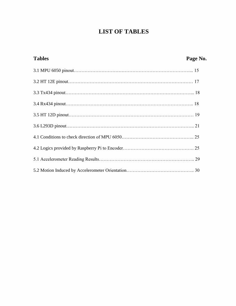
LIST OF TABLES
Tables Page No.
3.1 MPU 6050 pinout…………………………………………………………………... 15
3.2 HT 12E pinout……………………………………………………………………… 17
3.3 Tx434 pinout………………………………………………………………………... 18
3.4 Rx434 pinout……………………………………………………………………….. 18
3.5 HT 12D pinout……………………………………………………………………… 19
3.6 L293D pinout……………………………………………………………………….. 21
4.1 Conditions to check direction of MPU 6050……………………………………….. 25
4.2 Logics provided by Raspberry Pi to Encoder………………………………………. 25
5.1 Accelerometer Reading Results…………………………………………………….. 29
5.2 Motion Induced by Accelerometer Orientation…………………………………….. 30
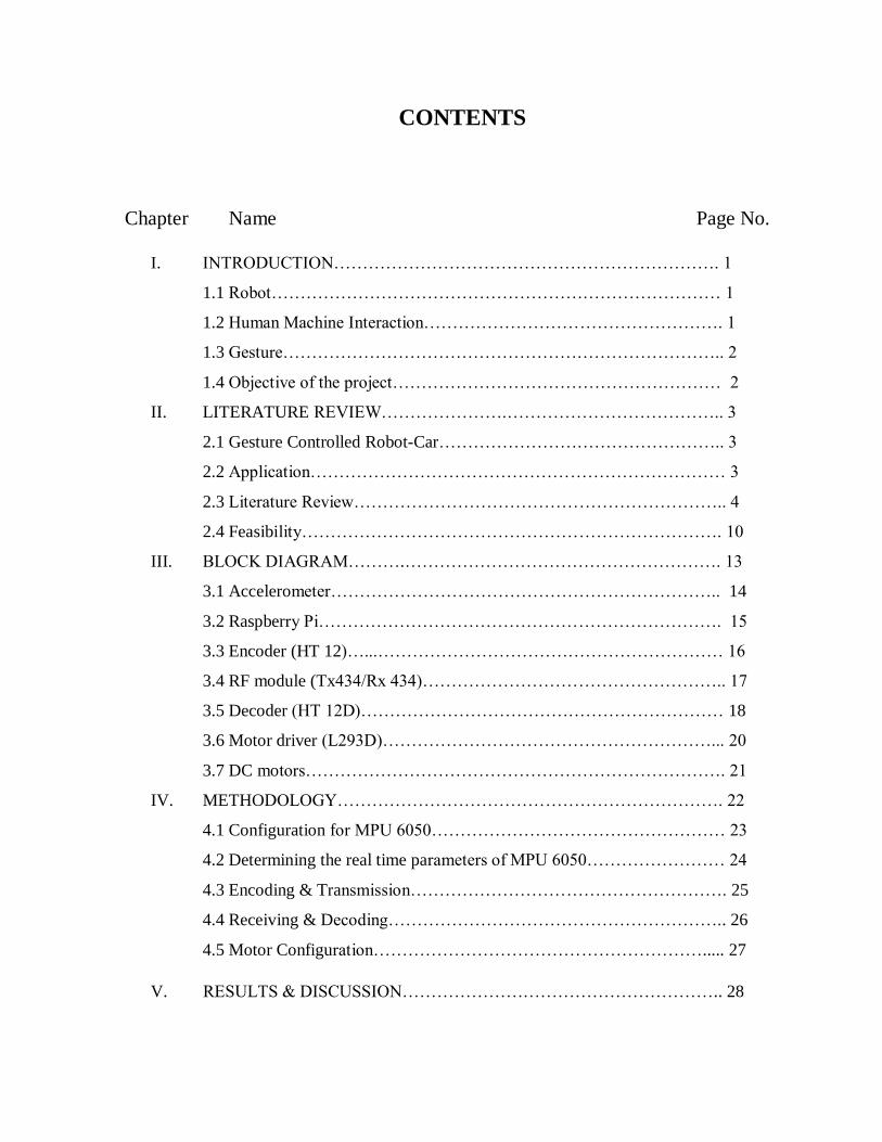
CONTENTS
Chapter Name Page No.
I. INTRODUCTION…………………………………………………………. 1
1.1 Robot…………………………………………………………………… 1
1.2 Human Machine Interaction……………………………………………. 1
1.3 Gesture………………………………………………………………….. 2
1.4 Objective of the project………………………………………………… 2
II. LITERATURE REVIEW………………….……………………………….. 3
2.1 Gesture Controlled Robot-Car………………………………………….. 3
2.2 Application……………………………………………………………… 3
2.3 Literature Review……………………………………………………….. 4
2.4 Feasibility………………………………………………………………. 10
III. BLOCK DIAGRAM……….………………………………………………. 13
3.1 Accelerometer………………………………………………………….. 14
3.2 Raspberry Pi……………………………………………………………. 15
3.3 Encoder (HT 12)…...…………………………………………………… 16
3.4 RF module (Tx434/Rx 434)…………………………………………….. 17
3.5 Decoder (HT 12D)……………………………………………………… 18
3.6 Motor driver (L293D)…………………………………………………... 20
3.7 DC motors………………………………………………………………. 21
IV. METHODOLOGY…………………………………………………………. 22
4.1 Configuration for MPU 6050…………………………………………… 23
4.2 Determining the real time parameters of MPU 6050…………………… 24
4.3 Encoding & Transmission………………………………………………. 25
4.4 Receiving & Decoding………………………………………………….. 26
4.5 Motor Configuration…………………………………………………..... 27
V. RESULTS & DISCUSSION……………………………………………….. 28

VI. CONCLUSION………………………………………………………… 31
6.1 Limitations and Future Work……………………………………….. 31
VII. REFERENCES…………………………………………………………. 32
VIII. APPENDIX……………………………………………………………... 35
Introduction/Chapter-I
AEIE, RCCIIT 1
CHAPTER I: INTRODUCTION
Gesture recognition is a topic in science and language technology with the goal of interpreting
human gestures via mathematical algorithms. Gestures can originate from any bodily motion or
state but commonly originate from the face or hand. Users can use simple gestures to control or
interact with devices without physically touching them. Many approaches have been made using
cameras and computer vision algorithms to interpret sign language. However, the identification
and recognition of posture, gait, proxemics, and human behaviors is also the subject of gesture
recognition techniques. Gesture recognition can be seen as a way for computers to begin to
understand human body language, thus building a richer bridge between machines and humans
than primitive text user interfaces or even GUIs (graphical user interfaces), which still limit the
majority of input to keyboard and mouse and interact naturally without any mechanical devices.
Using the concept of gesture recognition, it is possible to point a finger at this point will move
accordingly. This could make conventional input on devices such and even redundant.
1.1 ROBOT
A robot is usually an electro-mechanical machine that can perform tasks automatically. Some
robots require some degree of guidance, which may be done using a remote control or with a
computer interface. Robots can be autonomous, semi-autonomous or remotely controlled. Robots
have evolved so much and are capable of mimicking humans that they seem to have a mind of
their own.
1.2 HUMAN MACHINE INTERACTION
An important aspect of a successful robotic system is the Human-Machine interaction. In the
early years the only way to communicate with a robot was to program which required extensive
hard work. With the development in science and robotics, gesture based recognition came into
life. Gestures originate from any bodily motion or state but commonly originate from the face or
Introduction/Chapter-I
AEIE, RCCIIT 2
hand. Gesture recognition can be considered as a way for computer to understand human body
language. This has minimized the need for text interfaces and GUIs (Graphical User Interface).
1.3 GESTURE
A gesture is an action that has to be seen by someone else and has to convey some piece of
information. Gesture is usually considered as a movement of part of the body, esp. a hand or the
head, to express an idea or meaning.
1.4 OBJECTIVE OF THE PROJECT
The integration of more and more functionality into the human machine interface (HMI) of
vehicles increases the complexity of device handling. Thus optimal use of different human
sensory channels or gestures is an approach to simplify the interaction with in-car devices. Using
this idea, a car-robot can be implemented whose navigation can be done wirelessly with the help
of a Raspberry Pi.
Hand gesture recognition is an essential way for Human-Robot Interaction (HRI). Sign language
is the most intuitive and direct way to communication for impaired or disabled people.
The goal of this project is to capture simple hand gestures from the Glove and use that input to
wirelessly control a modified RC car. Controlled variable includes steering using an
accelerometer sensor. Testing showed that users were able to wear the glove and control the car
with only a small amount of instruction.
Literature Review/Chapter-II
AEIE, RCCIIT 3
CHAPTER II: LITERATURE REVIEW
2.1 GESTURE CONTROLLED CAR-ROBOT
Gesture recognition technologies are much younger in the world of today. At this time there is
much active research in the field and little in the way of publicly available implementations.
Several approaches have been developed for sensing gestures and controlling robots. Glove
based technique is a well-known means of recognizing hand gestures. It utilizes a sensor attached
to a glove that directly measures hand movements.
A Gesture Controlled robot is a kind of robot which can be controlled by hand gestures and not
the old fashioned way by using buttons. The user just needs to wear a small transmitting device
on his hand which includes a sensor which is an accelerometer in our case. Movement of the
hand in a specific direction will transmit a command to the robot which will then move in a
specific direction. The transmitting device includes a Comparator IC for assigning proper levels
to the input voltages from the accelerometer and an Encoder IC which is used to encode the four
bit data and then it will be transmitted by an RF Transmitter module.
At the receiving end an RF Receiver module will receive the encoded data and decode it by
using a decoder IC. This data is then processed by a microcontroller and passed onto a motor
driver to rotate the motors in a special configuration to make the robot move in the same
direction as that of the hand.
2.2 APPLICATION
The applications of the accelerometer based gesture controlled robot include:
Military applications to operate robots
Medical applications for the purpose of surgery
Construction field
In industries to control trolley and lift

Literature Review/Chapter-II
AEIE, RCCIIT 4
Gesture controlling is very helpful for handicapped and physically disabled people to
achieve certain tasks, such as driving a vehicle.
Gestures can be used to control interactions for entertainment purposes such as gaming to
make the game player's experience more interactive or immersive.
2.3 LITERATURE REVIEW
A hand-gesture-based control interface was introduced for navigating a car-robot in [1]. A 3-axis
accelerometer is adopted to record a user’s hand trajectories. The trajectory data is transmitted
wirelessly via an RF module to a computer. The received trajectories are then classified to one of
six control commands for navigating a car-robot. The classifier adopts the dynamic time warping
(DTW) algorithm to classify hand trajectories. Simulation results show that the classifier could
achieve 92.2% correct rate.
A novel, non-contact, pointing interface is being developed for control of non-safety critical
systems inside a vehicle with the aims of improving safety, decreasing manufacturing cost and
improving the ease of driver migration between different cars in [2]. A driver operates the
interface via an onscreen cursor using pointing gestures to be identified by a computer vision
system. This paper describes the vision subsystem responsible for detection and tracking of the
driver’s hands. To be robust, it must detect and track under varying lighting conditions with no
prior assumptions concerning the colour of the hands or clothing. Adaptive foreground and
background models are used for segmentation and a robust geometrical hand model is employed
for tracking. The system is demonstrated working at speeds close to real-time on a standard PC
using image sequences captured inside a car.
The integration of more and more functionality into the human machine interface (HMI) of
vehicles increases the complexity of device handling in [3]. Thus optimal use of different human
sensory channels is an approach to simplify the interaction with in-car devices. This way the user
convenience increases as much as distraction may decrease. In this paper a video based real time
Literature Review/Chapter-II
AEIE, RCCIIT 5
hand gesture recognition system for in-car use is presented. It was developed in course of
extensive usability studies. In combination with a gesture optimized HMI it allows intuitive and
effective operation of a variety of in-car multimedia and infotainment devices with hand poses
and dynamic hand gestures.
Envision to add context awareness and ambient intelligence to edutainment and computer
gaming applications in general was implemented in [4]. This requires mixed-reality setups and
ever-higher levels of immersive human-computer interaction. Here, the focus is on the automatic
recognition of natural human hand gestures recorded by inexpensive, wearable motion sensors.
To study the feasibility of this approach, an educational parking game was chosen with 3-D
graphics that employs motion sensors and hand gestures as its sole game controls. The
implementation prototype is based on Java-3D for the graphics display and on the CRN Toolbox
for sensor integration. It shows very promising results in practice regarding game appeal, player
satisfaction, extensibility, ease of interfacing to the sensors, and – last but not least – sufficient
accuracy of the real-time gesture recognition to allow for smooth game control. An initial
quantitative performance evaluation confirms these notions and provides further support for the
setup.
The primary and secondary driving task together with Human Machine Interface (HMI) trends
and issues which are driving automotive user interface designers to consider hand gesture
recognition as a realistic alternative for user controls are described in [5]. A number of hand
gesture recognition technologies and applications for Human Vehicle Interaction (HVI) are also
discussed including a summary of current automotive hand gesture recognition research.
Hand gesture recognition is an essential way for Human-Robot Interaction (HRI) . Sign language
is the most intuitive and direct way to communication for impaired or disabled people.
Furthermore, emotional interaction with human beings is desirable for robots. In this paper [6],
hand gesture recognition and emotion recognition of an integrated system will be described
which has ability to track multiple people at the same time, to recognize their facial expressions,
Literature Review/Chapter-II
AEIE, RCCIIT 6
and to identify social atmosphere. Consequently, robots can easily recognize hand gesture and
facial expression with emotion variations of different people, and can respond properly. A
combining hand gesture recognition algorithm which combines two distinct recognizers has been
studied. These two recognizers collectively determine the hand’s gesture via a process called
combinatorial approach recognizer (CAR) equation.
Automobiles are becoming increasingly important in daily life. However, people usually need to
cost lots of efforts and time to get their required services. On one hand, an automobile itself
consists of many physical processes to achieve its traditional functionality; on the other hand, it
is being integrated with more and more sensors and actuators, which makes it a typical cyber-
physical system. In order to provide friendly and human-centric services for users, the Intelligent
Cyber-Physical System for automobiles (iCPS-Car) for automobiles was proposed in [7]. iCPS-
Car integrates people, cars and cyber spaces together and provides natural interaction manners,
and personalized and continuous services.
It was attempted to narrow down the gap between real world and synthetic environment in [8].
For that purpose, an immersive driving car simulation was developed that combines tangible tool
with mixed reality environment. As tangible tool, a real physical mini car was deployed that
employ arduino sensor inside. To provide an immersive sensation among user and arduino mini
car, a camera belonging to a smart phone was employed in front of our car that will create real-
driving-sensation since the user will feel like he is sitting and driving inside the car. As car
controller, a natural user interface (NUI) controller was implemented that employ widely used
RGBD sensor, Kinect.
Multiple devices while driving steals drivers’ attention from the road and is becoming the cause
of accidents in 1 out of 3 cases. Many research efforts are being dedicated to design, manufacture
and test Human-Machine Interfaces that allow operating car devices without distracting the
drivers’ attention. A complete system for controlling the infotainment equipment through hand
gestures is explained in this paper. The system works with a visible-infrared camera mounted on
Literature Review/Chapter-II
AEIE, RCCIIT 7
the ceiling of the car and pointing to the shift-stick Area, and is based in a combination of some
new and some well-known computer vision algorithms in [9]. The system has been tested by 23
volunteers on a car simulator and a real vehicle and the results show that the users slightly prefer
this system to an equivalent one based on a touch-screen interface.
Humans and machines do not interface well. In an attempt to bridge the gap between humans and
the systems they interact with, a plethora of input methods have been devised: keyboards, mouse,
joysticks, game controllers and touch screens are just a few examples. Unfortunately, none of
these devices remove the barrier between man and machine. With the Magic Glove control
system in [10], the aim to remove this obstruction by allowing the user to control a hardware
device using natural gestures. The Magic Glove takes advantage of a multitude of sensors to
capture hand movements and uses this information control a device – in this case, a modified RC
car. The goal of this paper is to capture simple hand gestures from the Magic Glove and use that
input to wirelessly control a modified RC car. Controlled variables include speed, steering, lights
and sounds using a combination of flex, force and gyroscopic sensors. Multiple variables are
controlled simultaneously as Magic Glove outputs a constant control signal.
This paper [11] presents a method for two-hand pose recognition based on skeleton information,
aiming at the problem of low recognition rate and poor robustness in the field of human
computer interaction by single hand. This method consists of two steps: two-hand positional
information extraction and gesture recognition. In the first step, we utilize the Kinect depth
image to acquire the position of both hands. The second step is the highlight of the proposed
method, it locates the palms by hand nodes, extracts the right hand movement information which
is trained by a Hidden Markov Model. This method has been verified by a experimental car
control system and demonstrated good robustness in complex background environment.
To ensure safety and usability of advanced in-car cockpit solutions, prospective evaluation
during early prototyping stages is important, especially when developing innovative human-
cockpit-interactions. In this context, highly realistic test environments will help to provide
reliable and valid findings. Nevertheless, real car driving studies are difficult to control,
Literature Review/Chapter-II
AEIE, RCCIIT 8
manipulate, replicate and standardize. They are also more time consuming and expensive. One
economizing suggestion is the implementation of immersive driving environments within
simulator studies to provide users with a more realistic awareness of the situation in [12]. This
paper discusses research investigating the influence of immersive driving environments. Three
interaction modalities (touch, spin controller, free-hand gestures) and two levels of immersivity
(low, high) are examined to examine this methodology.
The recently developed Kinect sensor has opened a new horizon to Human-Computer Interface
(HCI) and its native connection with Microsoft’s product line of Xbox 360 and Xbox One video
game consoles makes completely hands-free control in next generation of gaming in [13]. Games
that requires a lot of degree of freedoms, especially the driving control of a car in racing games is
best suitable to be driven by gestures, as the use of simple buttons does not scale to the increased
number of assistive, comfort, and infotainment functions. In this paper, Mamdani type-I fuzzy
inference system based data processing module is proposed which effectively takes into account
the dependence of actual steering angle with the distance of two palm positions and angle
generated with respect to the sagittal plane. The FIS output variable controls the duration of a
virtual “key-pressed” event which mocks the users pressing of actual keys assigned to control car
direction in the original game. The acceleration and brake (deceleration) of the vehicle is
controlled using the relative displacement of left and right feet.
The notion of developing thought controlled devices (games, robots, cars etc.) is becoming
increasingly popular with the introduction of low cost commercial headsets that record neuro
electric activity and the extensive research in the area of Brain Computer Interfaces (BCIs). In
this paper [14], we study the feasibility of using a commercial low cost EEG amplifier which has
only limited number of electrodes, to develop a motor control BCI system. The objective is to
extract brain activity responsible for direction specific imagined and executed motor activity,
which can be used to identify the motor task performed by the user using the simultaneously
recorded EEG.
Literature Review/Chapter-II
AEIE, RCCIIT 9
Recently it is issued that the interaction technology for driver's gesture recognition in vehicular
environment. Drivers want to control the multimedia system, air conditioning system and other
applications which are equipped in head unit on dash board through the simple hands motion.
But, limited under the safety driving condition, gesture cognition while being in car has many
problems due to specific condition on road. In car, according to vehicle status such as forward
and backward moving or horizontal tilting, data errors of the motion sensors are caused and
unexpected driver's motion will be registered. In this paper [15], it is proposed the system model
for the gesture interaction between users and vehicle are defined and the data processing process
including specific hardware structure is adopted in order to reduce the motion sensing errors.
The past few years has shown a sudden spurt in the field of human computer interaction. The
days of using a mouse to control a computer is almost obsolete and people now prefer to use
touch screens and more recently, air gestures, for the same. However, the use of gestures is not
limited to computers alone. It finds its application in controlling televisions and other home
appliances as well. This paper [16] explores one such application where in air gestures could be
used to control automobiles. The paper describes a novel method to not only give directions but
also password-protect and use special features of the vehicle, using gestures. The complete
algorithm was developed using video processing on MATLAB 2011b and was found to be 3.6
times faster than its predecessor algorithms. The same was tested in real-time as well, using a
robot prototype and satisfactory results were obtained.
In this contribution [17], a novel approach to transform data is presented from time-of-flight
(ToF) sensors to be interpretable by Convolutional Neural Networks (CNNs). As ToF data tends
to be overly noisy depending on various factors such as illumination, reflection coefficient and
distance, the need for a robust algorithmic approach becomes evident. By spanning a three-
dimensional grid of fixed size around each point cloud we are able to transform three-
dimensional input to become processable by CNNs. This simple and effective neighborhood-
preserving methodology demonstrates that CNNs are indeed able to extract the relevant
information and learn a set of filters, enabling them to differentiate a complex set of ten different
gestures obtained from 20 different individuals and containing 600.000 samples overall.
Literature Review/Chapter-II
AEIE, RCCIIT 10
In this paper [18], we introduce a hand-gesture-based control interface for navigating a car-robot.
A 3-axis accelerometer is adopted to record a user's hand trajectories. The trajectory data is
transmitted wirelessly via an RF module to a computer. The received trajectories are then
classified to one of six control commands for navigating a car-robot. The classifier adopts the
dynamic time warping (DTW) algorithm to classify hand trajectories. Simulation results show
that the classifier could achieve 92.2% correct rate.
A research platform has been designed for a perceptually guided robot, which also serves as a
demonstrator for a coming generation of service robots in [19]. In order to operate semi-
autonomously, these require a capacity for learning about their environment and tasks, and will
have to interact directly with their human operators. Thus, they must be supplied with skills in
the fields of human-computer interaction, vision, and manipulation. GripSee is able to
autonomously grasp and manipulate objects on a table in front of it. The choice of object, the
grip to be used, and the desired final position are indicated by an operator using hand gestures.
Gesture interfaces are gaining relevance for human-machine communication, since it is expected
that they make interaction more intuitive. Particularly vision based approaches are widely
preferred. This paper [20] describes a novel vision based real-time gesture recognition system,
designed for operating in an automotive environment. It is used within an application for
retrieving traffic news and e-mails from a message storage. Image processing and pattern
matching techniques, specially adapted to the complex environmental conditions, represent the
systems basics.
2.4 FEASIBILITY
The Raspberry Pi 3 Model B is the third generation Raspberry Pi. This powerful credit-card sized
single board computer can be used for many applications and supersedes the original Raspberry
Pi Model B+ and Raspberry Pi 2 Model B.
Literature Review/Chapter-II
AEIE, RCCIIT 11
Whilst maintaining the popular board format the Raspberry Pi 3 Model B brings a more powerful
processor, which is 10 times faster than the first generation Raspberry Pi.
Additionally it adds wireless LAN & Bluetooth connectivity making it the ideal solution for
powerful connected designs.
MPU6050 sensor module is complete 6-axis Motion Tracking Device. It combines 3-axis
Gyroscope, 3-axis Accelerometer and Digital Motion Processor all in small package. Also, it has
additional feature of on-chip Temperature sensor. It has I2C bus interface to communicate with
the microcontrollers.
One of the main reasons as to why ADXL345 was not used is because this is an analog in nature
and it only serves as an accelerometer and not as a gyroscope. MPU 6050 uses I2C to
communicate with the Raspberry Pi 3B.
To reduce the cost of the project, only one microcomputer or controller has been used. Raspberry
Pi is being used in the transmitter side and RF module is used for transmission of data.
Software:
The programming language that was used in the Raspberry Pi for the project was Python.
Python is an interpreted, high-level, general purpose programming language. Python has a design
philosophy that emphasizes code readability, notably using significant whitespace. It provides
constructs that enable clear programming on both small and large scales.
Python features a dynamic type system and automatic memory management. It supports multiple
programming paradigms, including object-oriented, imperative, functional and procedural. It also
has a comprehensive standard library.
Hardware:
Accelerometer was chosen as a sensing device because it can measure the minute movements.
MPU 6050 is a six DOF (Degrees of Freedom) accelerometer which means it gives six values as
output – three from accelerometer and three from gyroscope. However, only the accelerometer
values were used for this project.
Literature Review/Chapter-II
AEIE, RCCIIT 12
Raspberry Pi is a single board microcomputer which has significantly more processing power
that most of the microcontrollers out there. It has GPIO pins, but it lacks the hardware control
and other peripherals found in a number of microcontrollers.
Block Diagram/Chapter-III
AEIE, RCCIIT 13
CHAPTER III: BLOCK DIAGRAM
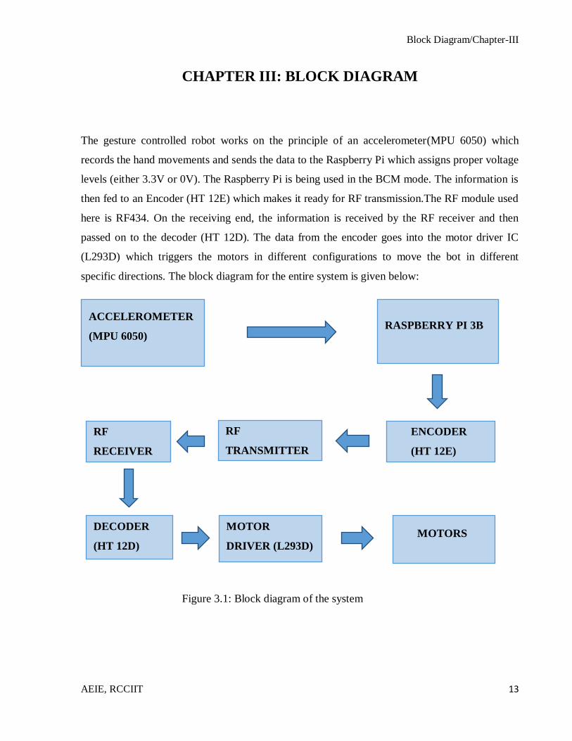
The gesture controlled robot works on the principle of an accelerometer(MPU 6050) which
records the hand movements and sends the data to the Raspberry Pi which assigns proper voltage
levels (either 3.3V or 0V). The Raspberry Pi is being used in the BCM mode. The information is
then fed to an Encoder (HT 12E) which makes it ready for RF transmission.The RF module used
here is RF434. On the receiving end, the information is received by the RF receiver and then
passed on to the decoder (HT 12D). The data from the encoder goes into the motor driver IC
(L293D) which triggers the motors in different configurations to move the bot in different
specific directions. The block diagram for the entire system is given below:
Figure 3.1: Block diagram of the system
ACCELEROMETER
(MPU 6050) RASPBERRY PI 3B
ENCODER
(HT 12E)
RF
TRANSMITTER
RF
RECEIVER
DECODER
(HT 12D)
MOTOR
DRIVER (L293D)
MOTORS

Block Diagram/Chapter-III
AEIE, RCCIIT 14
The entire system can be divided into two parts – one being the transmitter part which includes:
Accelerometer
Raspberry Pi
Encoder
RF transmitter
The other being the receiver part which includes:
RF receiver
Decoder
Motor driver
Motors.
3.1 ACCELEROMETER (MPU 6050)
An accelerometer is an electromechanical device that will measure acceleration forces. These
forces may be static, like the constant force of gravity pulling at your feet, or they could be
dynamic - caused by moving or vibrating the accelerometer.
It is a kind of sensor which records acceleration and gives an analog data while moving in X,Y,Z
direction or may be in X, Y direction only depending on the type of the sensor.
MPU6050 sensor module is complete 6-axis Motion Tracking Device. It combines 3-axis
Gyroscope, 3-axis Accelerometer and Digital Motion Processor all in small package. Also, it has
additional feature of on-chip Temperature sensor. It has I2C bus interface to communicate with
the microcontrollers.
Figure 3.2: MPU 6050

Block Diagram/Chapter-III
AEIE, RCCIIT 15
Table 3.1: MPU 6050 pinout:
Pin Number Symbol Function
1 VCC Provides power for the module, can be +3V to +5V.
Typically +5V is used
2 GND Connected to Ground of system
3 SCL Used for providing clock pulse for I2C Communication
4 SDA Used for transferring Data through I2C communication
5 XDA Auxiliary Serial Data pin. This pin is used to connect
other I2C interface enabled sensors SDA pin to
MPU6050
6 XCL Auxiliary Serial Clock pin. This pin is used to connect
other I2C interface enabled sensors SCL pin to
MPU6050
7 AD0 I2C Slave Address LSB pin. This is 0th bit in 7-bit slave
address of device. If connected to VCC then it is read as
logic one and slave address changes
8 INT Interrupt digital output pin
3.2 RASPBERRY PI
The Raspberry Pi 3 Model B is the third generation Raspberry Pi. This powerful credit-card sized
single board computer can be used for many applications and supersedes the original Raspberry
Pi Model B+ and Raspberry Pi 2 Model B.
Whilst maintaining the popular board format the Raspberry Pi 3 Model B brings a more powerful
processor, which is 10 times faster than the first generation Raspberry Pi.
Additionally it adds wireless LAN & Bluetooth connectivity making it the ideal solution for
powerful connected designs.
Figure 3.3: Raspberry Pi 3B
Block Diagram/Chapter-III
AEIE, RCCIIT 16
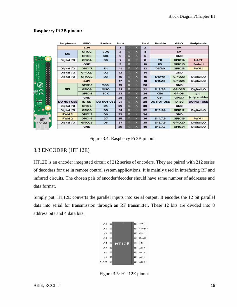
Raspberry Pi 3B pinout:
Figure 3.4: Raspberry Pi 3B pinout
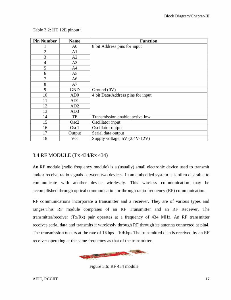
3.3 ENCODER (HT 12E)
HT12E is an encoder integrated circuit of 212 series of encoders. They are paired with 212 series
of decoders for use in remote control system applications. It is mainly used in interfacing RF and
infrared circuits. The chosen pair of encoder/decoder should have same number of addresses and
data format.
Simply put, HT12E converts the parallel inputs into serial output. It encodes the 12 bit parallel
data into serial for transmission through an RF transmitter. These 12 bits are divided into 8
address bits and 4 data bits.
Figure 3.5: HT 12E pinout
Block Diagram/Chapter-III
AEIE, RCCIIT 17
Table 3.2: HT 12E pinout:
Pin Number Name Function
1 A0 8 bit Address pins for input
2 A1
3 A2
4 A3
5 A4
6 A5
7 A6
8 A7
9 GND Ground (0V)
10 AD0 4 bit Data/Address pins for input
11 AD1
12 AD2
13 AD3
14 TE Transmission enable; active low
15 Osc2 Oscillator input
16 Osc1 Oscillator output
17 Output Serial data output
18 Vcc Supply voltage; 5V (2.4V-12V)
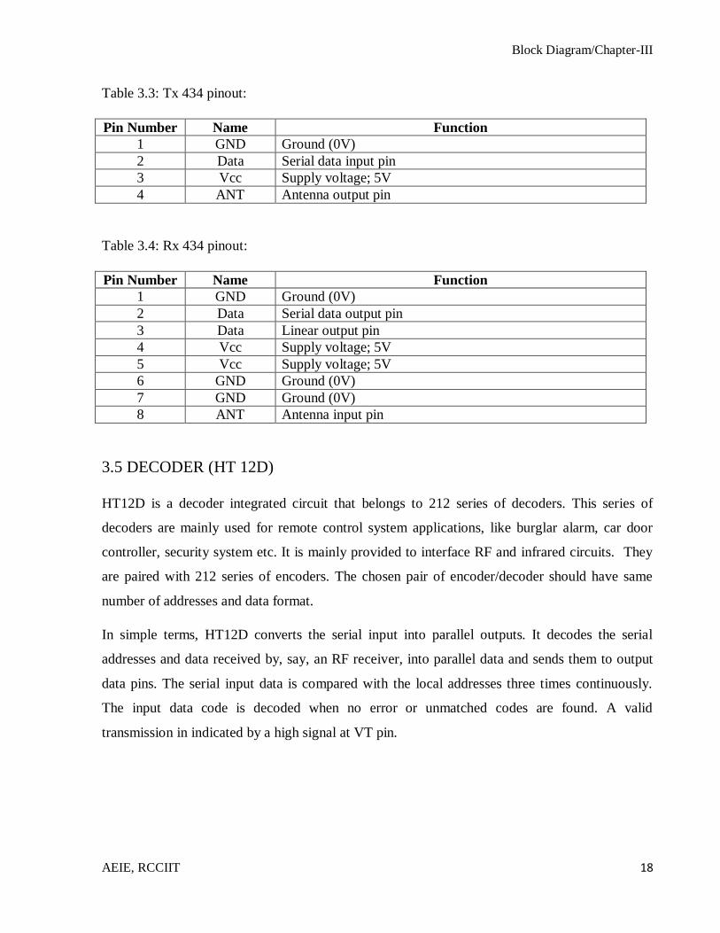
3.4 RF MODULE (Tx 434/Rx 434)
An RF module (radio frequency module) is a (usually) small electronic device used to transmit
and/or receive radio signals between two devices. In an embedded system it is often desirable to
communicate with another device wirelessly. This wireless communication may be
accomplished through optical communication or through radio frequency (RF) communication.
RF communications incorporate a transmitter and a receiver. They are of various types and
ranges.This RF module comprises of an RF Transmitter and an RF Receiver. The
transmitter/receiver (Tx/Rx) pair operates at a frequency of 434 MHz. An RF transmitter
receives serial data and transmits it wirelessly through RF through its antenna connected at pin4.
The transmission occurs at the rate of 1Kbps - 10Kbps.The transmitted data is received by an RF
receiver operating at the same frequency as that of the transmitter.
Figure 3.6: RF 434 module
Block Diagram/Chapter-III
AEIE, RCCIIT 18
Table 3.3: Tx 434 pinout:
Pin Number Name Function
1 GND Ground (0V)
2 Data Serial data input pin
3 Vcc Supply voltage; 5V
4 ANT Antenna output pin
Table 3.4: Rx 434 pinout:
Pin Number Name Function
1 GND Ground (0V)
2 Data Serial data output pin
3 Data Linear output pin
4 Vcc Supply voltage; 5V
5 Vcc Supply voltage; 5V
6 GND Ground (0V)
7 GND Ground (0V)
8 ANT Antenna input pin
3.5 DECODER (HT 12D)
HT12D is a decoder integrated circuit that belongs to 212 series of decoders. This series of
decoders are mainly used for remote control system applications, like burglar alarm, car door
controller, security system etc. It is mainly provided to interface RF and infrared circuits. They
are paired with 212 series of encoders. The chosen pair of encoder/decoder should have same
number of addresses and data format.
In simple terms, HT12D converts the serial input into parallel outputs. It decodes the serial
addresses and data received by, say, an RF receiver, into parallel data and sends them to output
data pins. The serial input data is compared with the local addresses three times continuously.
The input data code is decoded when no error or unmatched codes are found. A valid
transmission in indicated by a high signal at VT pin.
Block Diagram/Chapter-III
AEIE, RCCIIT 19
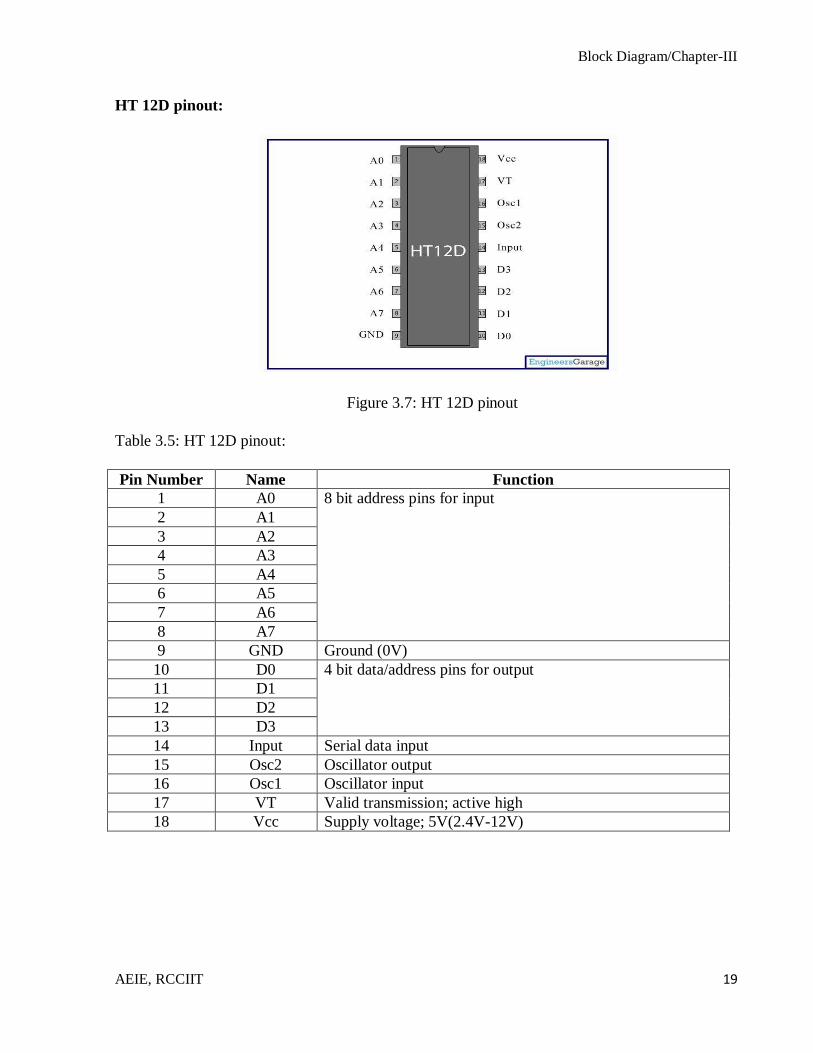
HT 12D pinout:
Figure 3.7: HT 12D pinout
Table 3.5: HT 12D pinout:
Pin Number Name Function
1 A0 8 bit address pins for input
2 A1
3 A2
4 A3
5 A4
6 A5
7 A6
8 A7
9 GND Ground (0V)
10 D0 4 bit data/address pins for output
11 D1
12 D2
13 D3
14 Input Serial data input
15 Osc2 Oscillator output
16 Osc1 Oscillator input
17 VT Valid transmission; active high
18 Vcc Supply voltage; 5V(2.4V-12V)

Block Diagram/Chapter-III
AEIE, RCCIIT 20
3.6 MOTOR DRIVER (L293D)
L293D is a dual H-bridge motor driver integrated circuit (IC). Motor drivers act as current
amplifiers since they take a low-current control signal and provide a higher-current signal. This
higher current signal is used to drive the motors.
L293D contains two inbuilt H-bridge driver circuits. In its common mode of operation, two DC
motors can be driven simultaneously, both in forward and reverse direction. The motor
operations of two motors can be controlled by input logic at pins 2 & 7 and 10 & 15. Input logic
00 or 11 will stop the corresponding motor. Logic 01 and 10 will rotate it in clockwise and
anticlockwise directions, respectively.
Enable pins 1 and 9 (corresponding to the two motors) must be high for motors to start operating.
When an enable input is high, the associated driver gets enabled. As a result, the outputs become
active and work in phase with their inputs. Similarly, when the enable input is low, that driver is
disabled, and their outputs are off and in the high-impedance state.
L293D pinout:
Figure 3.8: L293D motor driver pinout
Block Diagram/Chapter-III
AEIE, RCCIIT 21
Table 3.6: L293D pinout:
Pin Number Name Function
1 Enable 1,2 Enable pin for Motor 1; active high
2 Input 1 Input 1 for motor 1
3 Output 1 Output 1 for motor 1
4 GND Ground (0V)
5 GND Ground (0V)
6 Output 2 Output 2 for motor 1
7 Input 2 Input 2 for motor 1
8 Vcc 2 Supply voltage for motors; 9V-12V
9 Enable 3,4 Enable pin for Motor 2; active high
10 Input 3 Input 1 for motor 2
11 Output 3 Output 1 for motor 2
12 GND Ground (0V)
13 GND Ground (0V)
14 Output 4 Output 2 for motor 2
15 Input 4 Input 2 for motor 2
16 Vcc 1 Supply voltage; 5V
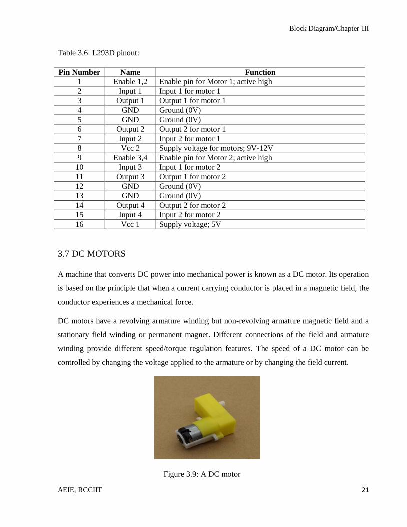
3.7 DC MOTORS
A machine that converts DC power into mechanical power is known as a DC motor. Its operation
is based on the principle that when a current carrying conductor is placed in a magnetic field, the
conductor experiences a mechanical force.
DC motors have a revolving armature winding but non-revolving armature magnetic field and a
stationary field winding or permanent magnet. Different connections of the field and armature
winding provide different speed/torque regulation features. The speed of a DC motor can be
controlled by changing the voltage applied to the armature or by changing the field current.
Figure 3.9: A DC motor
Methodology/Chapter-IV
AEIE, RCCIIT 22
CHAPTER IV: METHODOLOGY
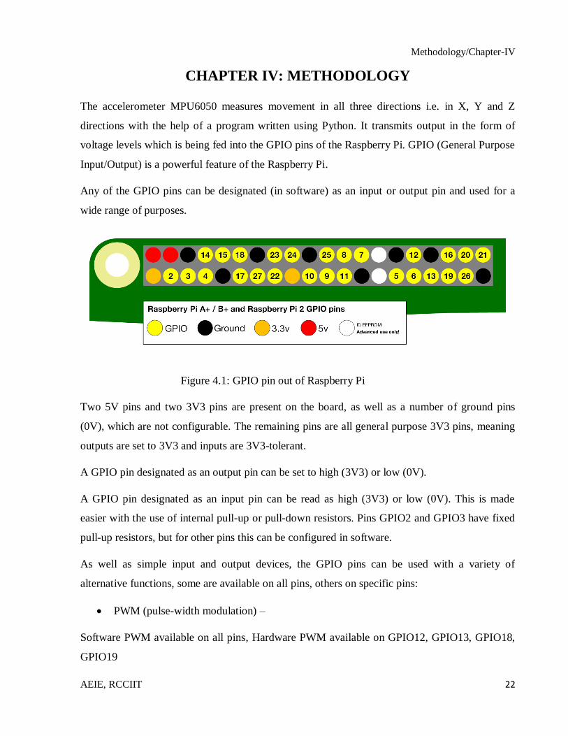
The accelerometer MPU6050 measures movement in all three directions i.e. in X, Y and Z
directions with the help of a program written using Python. It transmits output in the form of
voltage levels which is being fed into the GPIO pins of the Raspberry Pi. GPIO (General Purpose
Input/Output) is a powerful feature of the Raspberry Pi.
Any of the GPIO pins can be designated (in software) as an input or output pin and used for a
wide range of purposes.
Figure 4.1: GPIO pin out of Raspberry Pi
Two 5V pins and two 3V3 pins are present on the board, as well as a number of ground pins
(0V), which are not configurable. The remaining pins are all general purpose 3V3 pins, meaning
outputs are set to 3V3 and inputs are 3V3-tolerant.
A GPIO pin designated as an output pin can be set to high (3V3) or low (0V).
A GPIO pin designated as an input pin can be read as high (3V3) or low (0V). This is made
easier with the use of internal pull-up or pull-down resistors. Pins GPIO2 and GPIO3 have fixed
pull-up resistors, but for other pins this can be configured in software.
As well as simple input and output devices, the GPIO pins can be used with a variety of
alternative functions, some are available on all pins, others on specific pins:
PWM (pulse-width modulation) –
Software PWM available on all pins, Hardware PWM available on GPIO12, GPIO13, GPIO18,
GPIO19
Methodology/Chapter-IV
AEIE, RCCIIT 23
SPI -
SPI0: MOSI (GPIO10); MISO (GPIO9); SCLK (GPIO11); CE0 (GPIO8), CE1 (GPIO7)
SPI1: MOSI (GPIO20); MISO (GPIO19); SCLK (GPIO21); CE0 (GPIO18); CE1 (GPIO17);
CE2 (GPIO16)
I2C -
Data: (GPIO2); Clock (GPIO3)
EEPROM Data: (GPIO0); EEPROM Clock (GPIO1)
Serial -
TX (GPIO14); RX (GPIO15)
The code to find out about the GPIO pinout from the Pi itself is:
>>pinout
4.1 Configuration of MPU 6050
Installing smbus:
>>sudo apt-get install python-smbus i2c-tools
Enabling the I2C in RPi:
>>sudoraspi-config
Then including the i2c specification lines by these commands:
>>sudonano /etc/modules
These lines were added:
i2c-bcm2708
i2c-dev
Rebooting the Pi:
>>sudo reboot
Methodology/Chapter-IV
AEIE, RCCIIT 24
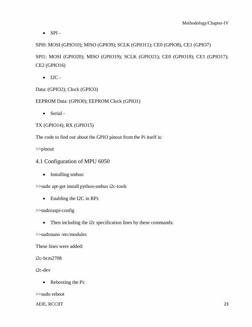
The interfacing was tested by using this following command. This would show the
address of the sensor connected to our pi:
>>sudo i2c detect -y 1
The port address of MPU 6050 is detected at 0x68.
Figure 4.2: Port address of MPU 6050 in Raspberry Pi
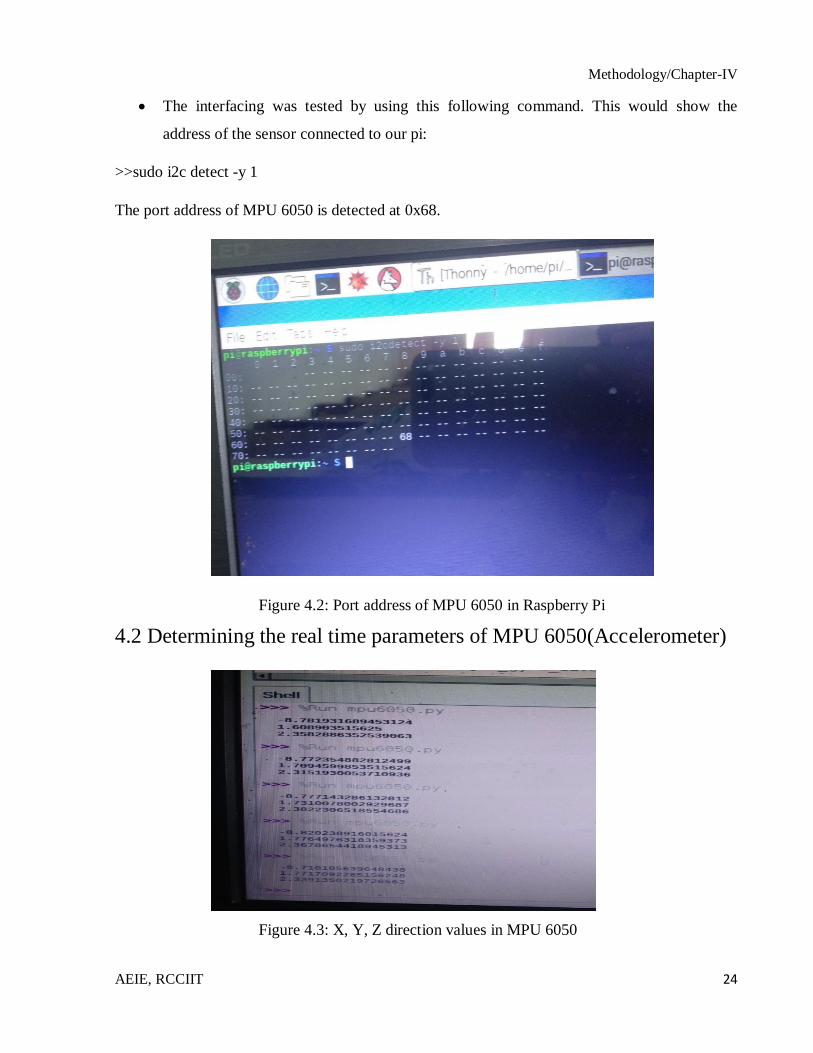
4.2 Determining the real time parameters of MPU 6050(Accelerometer)
Figure 4.3: X, Y, Z direction values in MPU 6050

Methodology/Chapter-IV
AEIE, RCCIIT 25
After calibrating the MPU 6050 with the help of the Python program in Raspberry Pi, the
following conditions were checked for direction with respect to the movement:
Table 4.1: Conditions to check direction of MPU 6050:
Case Condition Comments
I Z>8 Stop
Z<8 Check for direction with respect to
movement
II X<-2 Forward direction
X>3 Backward direction
Y>0 Right direction
Y<0 Left direction
All the conditions mentioned above were calibrated and the conditions for X and Y direction of
the MPU 6050 will only be considered if the condition for the Z direction is satisfied.
Depending upon the conditions found in MPU 6050, the values of four data pins (GPIO pins) of
Raspberry Pi are set or reset.
Table 4.2: Logics provided by Raspberry Pi to Encoder:
Data Pins Motor 1 Motor 2 Comments
D1 D2 D3 D4 D1 D2 D3 D4
1 0 1 0 1 0 1 0 Forward
0 1 0 1 0 1 0 1 Reverse
1 0 0 1 1 0 0 1 Left
0 1 1 0 0 1 1 0 Right
4.3 Encoding & Transmission
This binary logic from the Raspberry Pi go to the encoder (HT 12E). The four data pins act as
parallel input to the encoder. The encoder converts it into serial 4-bit data. This data is generated
at the output pin of the encoder.
Methodology/Chapter-IV
AEIE, RCCIIT 26
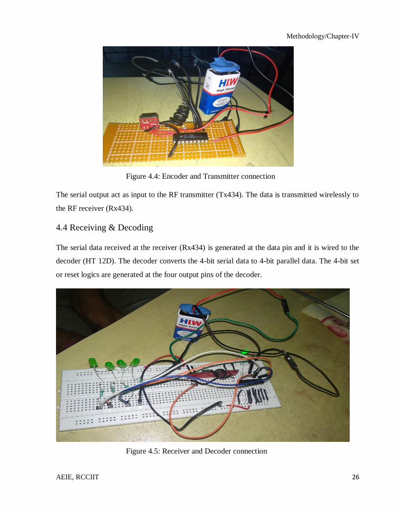
Figure 4.4: Encoder and Transmitter connection
The serial output act as input to the RF transmitter (Tx434). The data is transmitted wirelessly to
the RF receiver (Rx434).
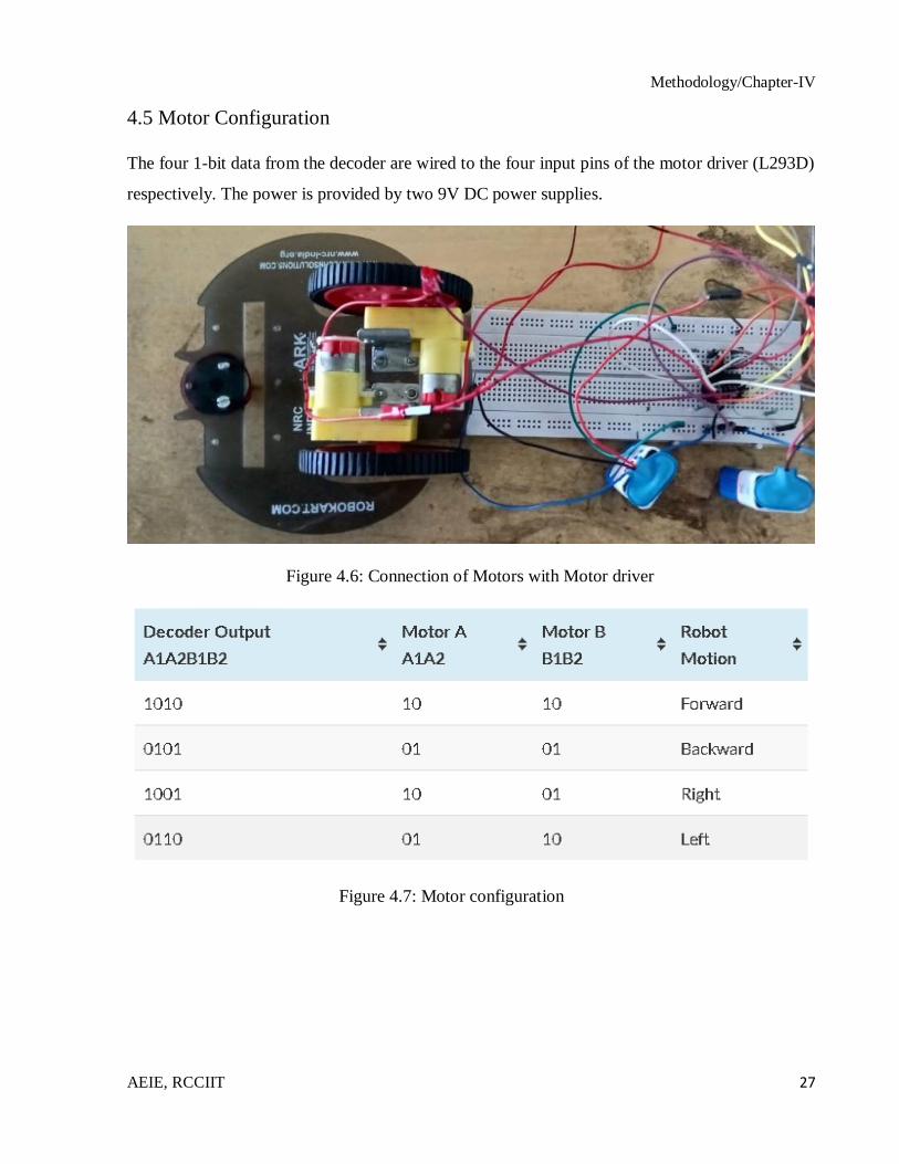
4.4 Receiving & Decoding
The serial data received at the receiver (Rx434) is generated at the data pin and it is wired to the
decoder (HT 12D). The decoder converts the 4-bit serial data to 4-bit parallel data. The 4-bit set
or reset logics are generated at the four output pins of the decoder.
Figure 4.5: Receiver and Decoder connection
Methodology/Chapter-IV
AEIE, RCCIIT 27
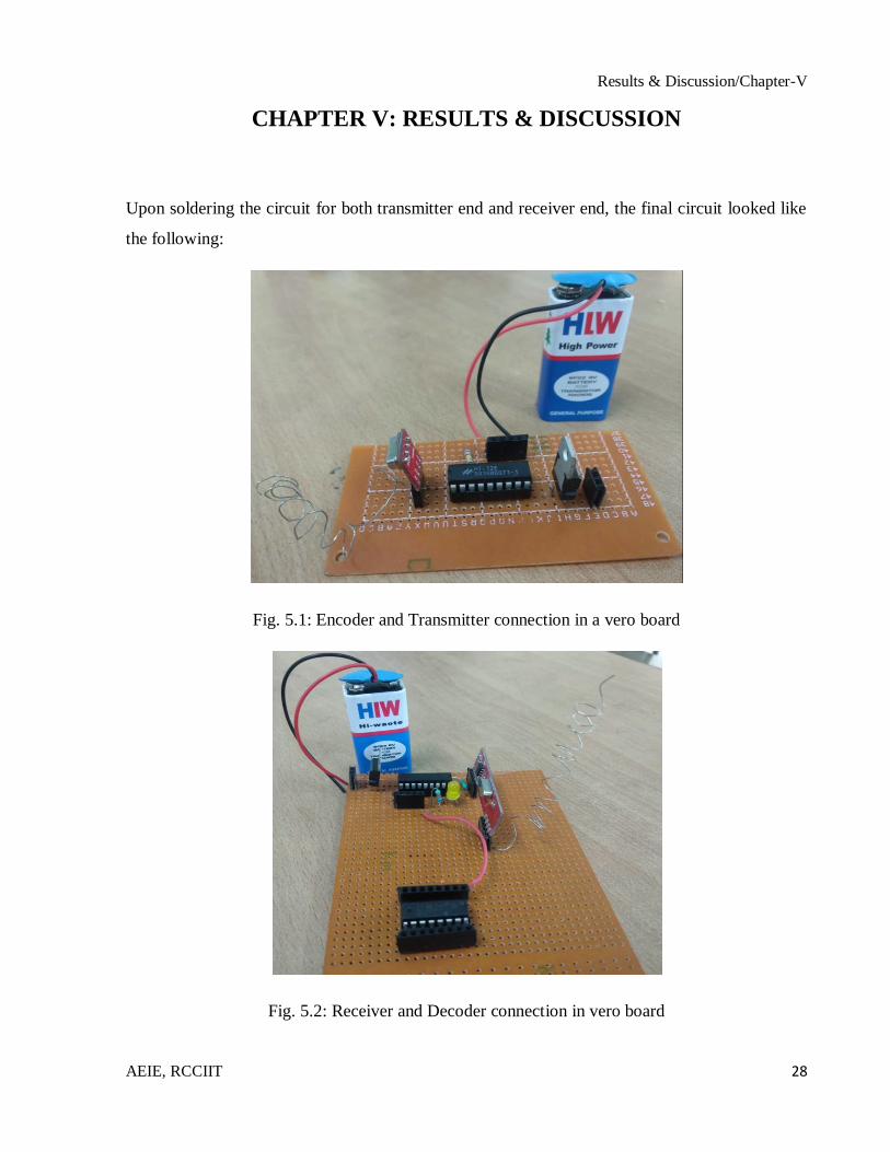
4.5 Motor Configuration
The four 1-bit data from the decoder are wired to the four input pins of the motor driver (L293D)
respectively. The power is provided by two 9V DC power supplies.
Figure 4.6: Connection of Motors with Motor driver
Figure 4.7: Motor configuration
Results & Discussion/Chapter-V
AEIE, RCCIIT 28
CHAPTER V: RESULTS & DISCUSSION
Upon soldering the circuit for both transmitter end and receiver end, the final circuit looked like
the following:
Fig. 5.1: Encoder and Transmitter connection in a vero board
Fig. 5.2: Receiver and Decoder connection in vero board
Results & Discussion/Chapter-V
AEIE, RCCIIT 29
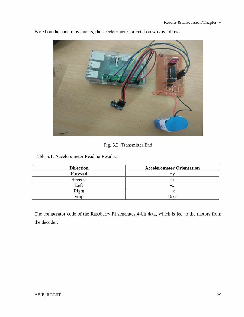
Based on the hand movements, the accelerometer orientation was as follows:
Fig. 5.3: Transmitter End
Table 5.1: Accelerometer Reading Results:
Direction Accelerometer Orientation
Forward +y
Reverse -y
Left -x
Right +x
Stop Rest
The comparator code of the Raspberry Pi generates 4-bit data, which is fed to the motors from
the decoder.

Results & Discussion/Chapter-V
AEIE, RCCIIT 30
Fig. 5.4: Receiver End
Table 5.2: Motion induced by Accelerometer Orientation:
Data Pins Motor 1 Motor 2 Car Movement Accelerometer
Orientation D1 D2 D3 D4 D1 D2 D3 D4
1 0 1 0 1 0 1 0 Forward +y
0 1 0 1 0 1 0 1 Reverse -y
1 0 0 1 1 0 0 1 Left -x
0 1 1 0 0 1 1 0 Right +x

Conclusion/Chapter-VI
AEIE, RCCIIT 31
CHAPTER VI: CONCLUSION
The main objective of the project was to build a robot-car that would run with the help of the
hand gestures obtained from the Accelerometer MPU 6050 using wireless RF communication. A
Raspberry Pi model 3B was used as a microcontroller. The car is showing proper movements for
the pre-determined and calibrated different hand gestures. The data from the hand movements
with the help of the accelerometer are fed into the Encoder HT 12E through the Raspberry Pi.
Then the values are transmitted with the help of Tx 434. Rx 434 receives the values in the
receiver part, where it is decoded by a Decoder HT 12D and sent to the motor driver L293D.
Thus motors are controlled with the data obtained from the motor driver.
The car only moves when the accelerometer is moved in a specific direction as per the given
calibrated values of the accelerometer.
6.1 Limitations & Future work:
The 9V batteries used offer only a limited amount of power to the system. Some alternate
source of power would be more helpful in place of batteries.
The RF module (RF 434) has a limited range of operation (around 500 feet). This
problem can be solved by utilizing a GSM module for wireless transmission. The GSM
infrastructure is installed almost all over the world. GSM will not only provide wireless
connectivity but also quite a large range.
Thirdly, an on-board camera can be installed for monitoring the robot from
farawayplaces. All we need is a wireless camera which will broadcast and a receiver
module which will provide live streaming.
References/Chapter-VII
AEIE, RCCIIT 32
REFERENCES
1. Xing-Han Wu, Mu-Chun Su, Pa-Chun Wang. A Hand-Gesture-Based Control Interface
for a Car-Robot. Proceedings of 2010 IEEE/RSJ International Conference on Intelligent
Robots and Systems, October 18-22, 2010, Taipei, Taiwan.
2. Gordon McAllistel, Stephen, J. McKenna, Ian W Ricketts. Towards a non-contact driver-
vehicle interface. Proceedings of 2000 IEEE Intelligent Transportation Systems
Conference Proceedings. Dearborn (MI), USA October l-3, 2000.
3. Martin Zobl, Michael Geigel, Bjom Schullec, Manfred Lang, Gerhard Rigoll. A realtime
system for hand gesture controlled operation of in-car devices. Proceedings of 2003
IEEE, ICME 2003.
4. David Bannach, Oliver Amft, Kai S. Kunze, Ernst A. Heinz, Gerhard Tr¨oster, Paul
Lukowicz . Waving Real Hand Gestures Recorded by Wearable Motion Sensors to a
Virtual Car and Driver in a Mixed-Reality Parking Game. Proceedings of the 2007 IEEE
Symposium on Computational Intelligence and Games (CIG 2007).
5. Carl A. Pickering, Keith J. Burnhamt, Michael J. Richardson. A Research Study of Hand
Gesture Recognition Technologies and Applications for Human Vehicle Interaction.
Jaguar and Land Rover Technical Research, UK, Jaguar Cars, Engineering Centre,
Whitley, Coventry. Coventry University, UK, Control Theory and Applications Centre,
Priory Street, Coventry.
6. Ren C. Luo. Confidence Fusion Based Human-Robot Interaction with Hand Gesture and
Emotion Recognition for Service Robotics. Proceedings of CINTI 2012, 13th IEEE
International Symposium on Computational Intelligence and Informatics, 20–22
November, 2012, Budapest, Hungary.
7. Sha Zhao, Shijian Li, Longbiao Chen, Yang Ding, ZemingZheng, Gang Pan. iCPS-Car:
An Intelligent Cyber-Physical System for Smart Automobiles. Proceedings of 2013
IEEE. DOI 10.11.09
8. Han Jia Qi, Markus Santoso. Immersive Driving Car Simulation for Children using
Natural User Interface Controller. Proceedings of 2013 IEEE. DOI
10.11.09/ISUVR.2013.17.
9. Francisco Parada-Loira, Elisardo González-Agulla, José L. Alba-Castro. Hand Gestures
to Control Infotainment Equipment in Cars. Proceedings of 2014 IEEE Intelligent
Vehicles Symposium (IV), June 8-11, 2014. Dearborn, Michigan, USA.
10. Akshay Dekate, Anam Kamal, Surekha K.S. MAGIC GLOVE- WIRELESS HAND
GESTURE HARDWARE CONTROLLER.
11. Tong Zhang, Aiyu Lu, Zhichao Huang. Both Hands Pose Recognition Control System
Based on Skeleton Tracking. Proceedings of 2014 IEEE.
12. Diana Reich, Rainer Stark. The Influence of Immersive Driving Environments on
Human-Cockpit Evaluations. Proceedings of 2015 IEEE, DOI 10.1109/HICSS.2015.69.
13. Chiranjib Saha, Debdipta Goswami, Sriparna Saha, Amit Konar, Anna Lekovay, Atulya
K. Nagarz. A Novel Gesture Driven Fuzzy Interface System For Car Racing Game.
References/Chapter-VII
AEIE, RCCIIT 33
14. Neethu Robinson, A. P. Vinod. Bi-directional imagined hand movement classification
using low cost EEG-based BCI. Proceedings of 2015 IEEE, DOI
10.1109/SMC.2015.544.
15. Sang-Yub Lee, Jae-Kyu Lee, Jae-Jin Ko. Implementation of System Model applied to
Wearable Device Platform for the User’s Gesture Recognition in Vehicular Environment.
Proceedings of 2015 IEEE, DOI 10.1109/FGCN.2015.14.
16. Sudhir Rao Rupanagudi, Varsha G. Bhat, Supriya R, Riya Dubey, Suma Sukumar,
Srabanti Karmarkar, Amulya K, Ankita Raman, Devika Indrani, Abhiram Srisai,
Mahathy Rajagopalan, Vaishnavi Venkatesh, Nupur Jain. A Novel and Secure
Methodology for Keyless Ignition and Controlling an Automobile using Air Gestures.
Proceedings of 2016 Intl. Conference on Advances in Computing, Communications and
Informatics (ICACCI), Sept. 21-24, 2016, Jaipur, India. 978-1-5090-2029-4/16/@2016
IEEE.
17. Fabian Sachara, Thomas Kopinski, Alexander Gepperth, UweHandmann. Free-hand
Gesture Recognition with 3D-CNNs for In-car Infotainment Control in Real-time.
Proceedings of 2017 IEEE.
18. Xing-Han Wu, Mu-Chun Su, Pa-Chun Wang. A hand-gesture-based control interface for
a car-robot. Proceedings of 10.1109/IROS.2010.5650294, IEEE. 03 December 2010.
19. Mark Becker, Efthimia Kefalea, Eric Maël, Christoph Von Der Malsburg, Mike Pagel,
Jochen Triesch, Jan C. Vorbrüggen, Rolf P. Würtz, Stefan Zadel. A Gesture-Controlled
Robot for Object Perception and Manipulation. Proceedings of Autonomous Robots,
April 1999, Volume 6, Issue 2, pp 203–221.
20. Suat Akyol, Ulrich Canzler, Klaus Bengler, Wolfgang Hahn. Gesture Control for use in
Automobiles. Proceedings of MVA2000, IAPR Workshop on Machine Vision
Applications. Nov. 28-30. 2000. The University of Tokyo, Japan.
21. https://www.electronicwings.com/raspberry-pi/mpu6050-accelerometergyroscope-
interfacing-with-raspberry-pi
22. http://www.circuitstoday.com/gesture-controlled-robot-raspberry-pi
23. https://circuitdigest.com/microcontroller-projects/rf-remote-controlled-leds-using-
raspberry-pi
24. https://www.slideshare.net/mahkamkhan/wireless-gesture-controlled-robot-fyp-report
25. https://www.raspberrypi.org/documentation/usage/gpio/images/gpio-numbers-pi2.png
26. https://www.dhresource.com/260x260s/f2-albu-g5-M00-50-59-
rBVaJFlHom2AH1_1AAQOVIqxkAE259.jpg/6v-bend-of-uniaxial-gear-motor-tt-
deceleration.jpg
27. https://www.engineersgarage.com/sites/default/files/HT12D_1.jpg
28. https://kitskart.com/wp-content/uploads/2018/01/51n43E9TJRL._SL1000_.jpg
29. https://www.engineersgarage.com/sites/default/files/HT12E.jpg
30. https://docs.particle.io/assets/images/pi-pinout-diagram-01.png
31. https://www.raspberrypi.org/app/uploads/2017/05/Raspberry-Pi-3-Ports-1-1833x1080.jpg
32. https://www.makerlab-electronics.com/my_uploads/2015/05/mpu-6050-1.jpg
33. http://seminarprojects.com/s/hand-gesture-controlled-robot-ppt
34. https://www.slideshare.net/neeraj18290/wireless-gesture-controlled-tank-toy-transmitter

References/Chapter-VII
AEIE, RCCIIT 34
35. http://www.webstatschecker.com/stats/keyword/a_hand_gesture_based_control_interface
for_a_car_robot
36. http://www.robotplatform.com/howto/L293/motor_driver_1.html
37. http://en.wikipedia.org/wiki/Gesture_interface
38. http://www.scribd.com/doc/98400320/InTech-Real-Time-Robotic-Hand-Control-Using-
Hand-Gestures
39. https://circuitdigest.com/electronic-circuits/rf-transmitter-and-receiver-circuit-diagram

Appendix/Chapter-VIII
AEIE, RCCIIT 35
APPENDIX
Raspberry Pi 3B datasheet:
Raspberry Pi 3B pinout:
MPU 6050 datasheet:
Features:
Gyroscope Features:
The triple-axis MEMS gyroscope in the MPU-60X0 includes a wide range of features:
Digital-output X-, Y-, and Z-Axis angular rate sensors (gyroscopes) with a user-
programmable full-scale range of ±250, ±500, ±1000, and ±2000°/sec
Appendix/Chapter-VIII
AEIE, RCCIIT 36
External sync signal connected to the FSYNC pin supports image, video and GPS
synchronization
Integrated 16-bit ADCs enable simultaneous sampling of gyros
Enhanced bias and sensitivity temperature stability reduces the need for user calibration
Improved low-frequency noise performance
Digitally-programmable low-pass filter
Gyroscope operating current: 3.6mA
Standby current: 5μA
Factory calibrated sensitivity scale factor
User self-test
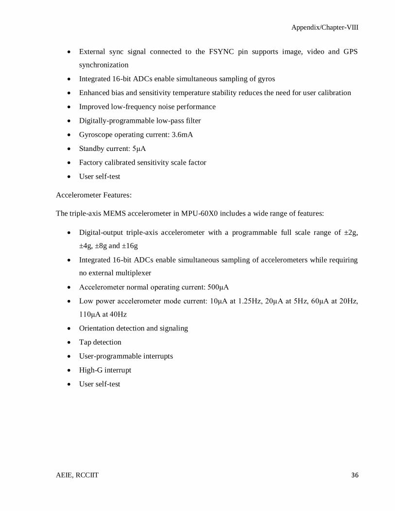
Accelerometer Features:
The triple-axis MEMS accelerometer in MPU-60X0 includes a wide range of features:
Digital-output triple-axis accelerometer with a programmable full scale range of ±2g,
±4g, ±8g and ±16g
Integrated 16-bit ADCs enable simultaneous sampling of accelerometers while requiring
no external multiplexer
Accelerometer normal operating current: 500μA
Low power accelerometer mode current: 10μA at 1.25Hz, 20μA at 5Hz, 60μA at 20Hz,
110μA at 40Hz
Orientation detection and signaling
Tap detection
User-programmable interrupts
High-G interrupt
User self-test

Appendix/Chapter-VIII
AEIE, RCCIIT 37
MPU 6050 pinout:
Pin Number Symbol Function
1 VCC Provides power for the module, can be +3V to +5V.
Typically +5V is used
2 GND Connected to Ground of system
3 SCL Used for providing clock pulse for I2C Communication
4 SDA Used for transferring Data through I2C communication
5 XDA Auxiliary Serial Data pin. This pin is used to connect
other I2C interface enabled sensors SDA pin to
MPU6050
6 XCL Auxiliary Serial Clock pin. This pin is used to connect
other I2C interface enabled sensors SCL pin to
MPU6050
7 AD0 I2C Slave Address LSB pin. This is 0th bit in 7-bit slave
address of device. If connected to VCC then it is read as
logic one and slave address changes
8 INT Interrupt digital output pin
HT12D datasheet:
Features:
Operating voltage: 2.4V~12V
Low power and high noise immunity CMOStechnology
Low standby current
Capable of decoding 12 bits of information
Binary address setting
Received codes are checked 3 times
Address/Data number combination
8 address bits and 4 data bits
Appendix/Chapter-VIII
AEIE, RCCIIT 38
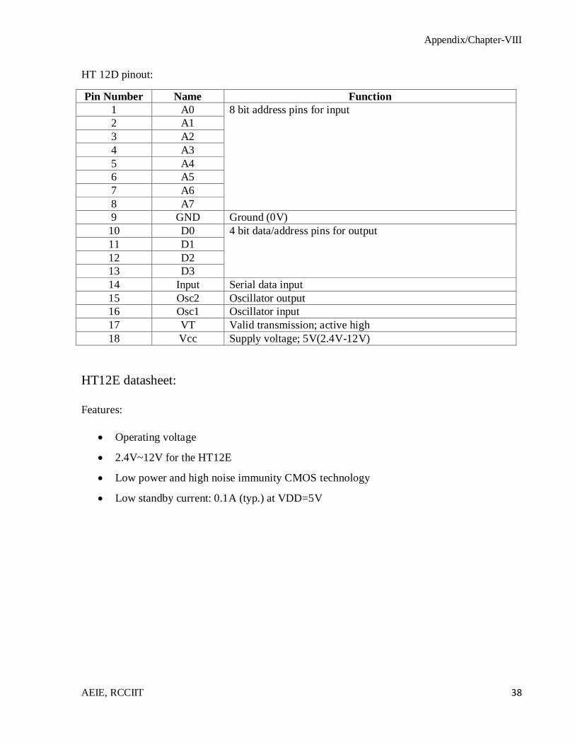
HT 12D pinout:
Pin Number Name Function
1 A0 8 bit address pins for input
2 A1
3 A2
4 A3
5 A4
6 A5
7 A6
8 A7
9 GND Ground (0V)
10 D0 4 bit data/address pins for output
11 D1
12 D2
13 D3
14 Input Serial data input
15 Osc2 Oscillator output
16 Osc1 Oscillator input
17 VT Valid transmission; active high
18 Vcc Supply voltage; 5V(2.4V-12V)
HT12E datasheet:
Features:
Operating voltage
2.4V~12V for the HT12E
Low power and high noise immunity CMOS technology
Low standby current: 0.1A (typ.) at VDD=5V
Appendix/Chapter-VIII
AEIE, RCCIIT 39
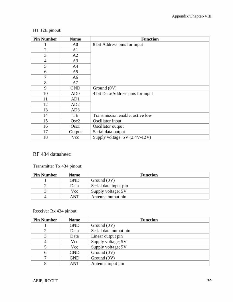
HT 12E pinout:
Pin Number Name Function
1 A0 8 bit Address pins for input
2 A1
3 A2
4 A3
5 A4
6 A5
7 A6
8 A7
9 GND Ground (0V)
10 AD0 4 bit Data/Address pins for input
11 AD1
12 AD2
13 AD3
14 TE Transmission enable; active low
15 Osc2 Oscillator input
16 Osc1 Oscillator output
17 Output Serial data output
18 Vcc Supply voltage; 5V (2.4V-12V)
RF 434 datasheet:
Transmitter Tx 434 pinout:
Pin Number Name Function
1 GND Ground (0V)
2 Data Serial data input pin
3 Vcc Supply voltage; 5V
4 ANT Antenna output pin
Receiver Rx 434 pinout:
Pin Number Name Function
1 GND Ground (0V)
2 Data Serial data output pin
3 Data Linear output pin
4 Vcc Supply voltage; 5V
5 Vcc Supply voltage; 5V
6 GND Ground (0V)
7 GND Ground (0V)
8 ANT Antenna input pin

Appendix/Chapter-VIII
AEIE, RCCIIT 40
L293D datasheet:
L293D pinout:
Pin Number Name Function
1 Enable 1,2 Enable pin for Motor 1; active high
2 Input 1 Input 1 for motor 1
3 Output 1 Output 1 for motor 1
4 GND Ground (0V)
5 GND Ground (0V)
6 Output 2 Output 2 for motor 1
7 Input 2 Input 2 for motor 1
8 Vcc 2 Supply voltage for motors; 9V-12V
9 Enable 3,4 Enable pin for Motor 2; active high
10 Input 3 Input 1 for motor 2
11 Output 3 Output 1 for motor 2
12 GND Ground (0V)
13 GND Ground (0V)
14 Output 4 Output 2 for motor 2
15 Input 4 Input 2 for motor 2
16 Vcc 1 Supply voltage; 5V