Design Pattern Detection Using Similarity Scoring
14
Design Pattern Detection Using Similarity Scoring Nikolaos Tsantalis, Alexander Chatzigeorgiou, Member, IEEE Computer Society, George Stephanides, Member, IEEE Computer Society, and Spyros T. Halkidis Abstract—The identification of design patterns as part of the reengineering process can convey important information to the designer. However, existing pattern detection methodologies generally have problems in dealing with one or more of the following issues: Identification of modified pattern versions, search space explosion for large systems and extensibility to novel patterns. In this paper, a design pattern detection methodology is proposed that is based on similarity scoring between graph vertices. Due to the nature of the underlying graph algorithm, this approach has the ability to also recognize patterns that are modified from their standard representation. Moreover, the approach exploits the fact that patterns reside in one or more inheritance hierarchies, reducing the size of the graphs to which the algorithm is applied. Finally, the algorithm does not rely on any pattern-specific heuristic, facilitating the extension to novel design structures. Evaluation on three open-source projects demonstrated the accuracy and the efficiency of the proposed method. Index Terms—Patterns, object-oriented design methods, graph algorithms, restructuring, reverse engineering, reengineering. Ç 1 INTRODUCTION D ESIGN patterns are generally defined as descriptions of communicating classes that form a common solution to a common design problem. Since the publication of the most well-known catalog of patterns [15], they have widely and rapidly attracted the interest of the software engineer- ing community. Their proponents argue that their use leads to the construction of well-structured, maintainable, and reusable software systems. Because most current software projects deal with evolving products consisting of a large number of compo- nents, their architecture can become complicated and quite messy. Design patterns can impose structure on the system due to the abstractions being used. Consequently, the identification of implemented design patterns could be useful for the comprehension of an existing design and provides the ground for further improvements [30]. In the proposed methodology, both the system under study as well as the design pattern to be detected are described in terms of graphs. In particular, the approach employs a set of matrices representing all important aspects of their static structure. For the detection of patterns, we employ a graph similarity algorithm [7], which takes as input both the system and the pattern graph and calculates similarity scores between their vertices. The major advantage of this approach is the ability to detect not only patterns in their basic form (the one usually found in the literature) but also modified versions of them (given that the modification is limited to one pattern characteristic). This is a significant prerequi- site since any design pattern may be implemented with myriad variations [13], [26]. One of the most important challenges in pattern detection is the size of the exploration space for large software systems. A combinatorial explosion can occur due to the great number of system classes and the multiple roles that classes can play in a specific design pattern. The application of the above-mentioned similarity algorithm to the entire system would lead to efficiency problems due to the slow convergence of the algorithm. Moreover, the difficulty in combining the results that constitute an actual pattern candidate could pose problems regarding accuracy. To handle this issue, the proposed approach exploits the fact that each design pattern resides in one or more inheritance hierarchies since most patterns involve at least one abstract class/interface and its descendants. Consequently, the system is partitioned to clusters of hierarchies (pairs of communicating hierarchies), so that the similarity algorithm is applied to smaller subsystems rather than to the entire system. Another important issue is that the list of design patterns is continuously expanding. As a result, a detection methodology should not be based on specific patterns. Any algorithm should be able to generalize its applicability to user-specified patterns that might not have been invented so far. Since the employed similarity algorithm does not rely on any heuristic that would take advantage of a specific static structure, the proposed methodology can be applied to any pattern input. The proposed methodology has been evaluated on JHotDraw [18], JRefactory [19], and JUnit [20], which are open-source projects extensively and systematically 896 IEEE TRANSACTIONS ON SOFTWARE ENGINEERING, VOL. 32, NO. 11, NOVEMBER 2006 . The authors are with the Department of Applied Informatics, University of Macedonia, 156 Egnatia str., 54006 Thessaloniki, Greece. E-mail: [email protected], {achat, steph, halkidis}@uom.gr. Manuscript received 10 Nov. 2005; revised 5 June 2006; accepted 12 Sept. 2006; published online 6 Nov. 2006. Recommended for acceptance by M. Harman. For information on obtaining reprints of this article, please send e-mail to: [email protected], and reference IEEECS Log Number TSE-0302-1105. 0098-5589/06/$20.00 ß 2006 IEEE Published by the IEEE Computer Society
Transcript of Design Pattern Detection Using Similarity Scoring

Design Pattern DetectionUsing Similarity Scoring
Nikolaos Tsantalis, Alexander Chatzigeorgiou, Member, IEEE Computer Society,
George Stephanides, Member, IEEE Computer Society, and Spyros T. Halkidis
Abstract—The identification of design patterns as part of the reengineering process can convey important information to the designer.
However, existing pattern detection methodologies generally have problems in dealing with one or more of the following issues:
Identification of modified pattern versions, search space explosion for large systems and extensibility to novel patterns. In this paper, a
design pattern detection methodology is proposed that is based on similarity scoring between graph vertices. Due to the nature of the
underlying graph algorithm, this approach has the ability to also recognize patterns that are modified from their standard
representation. Moreover, the approach exploits the fact that patterns reside in one or more inheritance hierarchies, reducing the size
of the graphs to which the algorithm is applied. Finally, the algorithm does not rely on any pattern-specific heuristic, facilitating the
extension to novel design structures. Evaluation on three open-source projects demonstrated the accuracy and the efficiency of the
proposed method.
Index Terms—Patterns, object-oriented design methods, graph algorithms, restructuring, reverse engineering, reengineering.
Ç
1 INTRODUCTION
DESIGN patterns are generally defined as descriptions of
communicating classes that form a common solution to
a common design problem. Since the publication of the
most well-known catalog of patterns [15], they have widely
and rapidly attracted the interest of the software engineer-
ing community. Their proponents argue that their use leadsto the construction of well-structured, maintainable, and
reusable software systems.
Because most current software projects deal with
evolving products consisting of a large number of compo-
nents, their architecture can become complicated and quite
messy. Design patterns can impose structure on the system
due to the abstractions being used. Consequently, the
identification of implemented design patterns could be
useful for the comprehension of an existing design and
provides the ground for further improvements [30].
In the proposed methodology, both the system under
study as well as the design pattern to be detected are
described in terms of graphs. In particular, the approach
employs a set of matrices representing all important
aspects of their static structure. For the detection of
patterns, we employ a graph similarity algorithm [7],
which takes as input both the system and the pattern
graph and calculates similarity scores between their
vertices. The major advantage of this approach is the
ability to detect not only patterns in their basic form (the
one usually found in the literature) but also modified
versions of them (given that the modification is limited to
one pattern characteristic). This is a significant prerequi-
site since any design pattern may be implemented with
myriad variations [13], [26].
One of the most important challenges in pattern detection
is the size of the exploration space for large software
systems. A combinatorial explosion can occur due to the
great number of system classes and the multiple roles that
classes can play in a specific design pattern. The application
of the above-mentioned similarity algorithm to the entire
system would lead to efficiency problems due to the slow
convergence of the algorithm. Moreover, the difficulty in
combining the results that constitute an actual pattern
candidate could pose problems regarding accuracy. To
handle this issue, the proposed approach exploits the fact
that each design pattern resides in one or more inheritance
hierarchies since most patterns involve at least one abstract
class/interface and its descendants. Consequently, the
system is partitioned to clusters of hierarchies (pairs of
communicating hierarchies), so that the similarity algorithm
is applied to smaller subsystems rather than to the entire
system.
Another important issue is that the list of design patterns
is continuously expanding. As a result, a detection
methodology should not be based on specific patterns.
Any algorithm should be able to generalize its applicability
to user-specified patterns that might not have been invented
so far. Since the employed similarity algorithm does not
rely on any heuristic that would take advantage of a specific
static structure, the proposed methodology can be applied
to any pattern input.The proposed methodology has been evaluated on
JHotDraw [18], JRefactory [19], and JUnit [20], which areopen-source projects extensively and systematically
896 IEEE TRANSACTIONS ON SOFTWARE ENGINEERING, VOL. 32, NO. 11, NOVEMBER 2006
. The authors are with the Department of Applied Informatics, University ofMacedonia, 156 Egnatia str., 54006 Thessaloniki, Greece.E-mail: [email protected], {achat, steph, halkidis}@uom.gr.
Manuscript received 10 Nov. 2005; revised 5 June 2006; accepted 12 Sept.2006; published online 6 Nov. 2006.Recommended for acceptance by M. Harman.For information on obtaining reprints of this article, please send e-mail to:[email protected], and reference IEEECS Log Number TSE-0302-1105.
0098-5589/06/$20.00 � 2006 IEEE Published by the IEEE Computer Society

employing design patterns. The results have been validatedagainst internal and external documentation of thosesystems. For the design patterns that have been examined,the number of false negatives was limited while falsepositives have not been found.
A number of patterns which are implemented in these
projects differ from the basic structure that usually appears
in textbooks. Therefore, the identification of such modified
patterns is not a trivial task [26]. However, according to the
results, similarity scoring is resistant to such kind of
modifications since it correctly identified those instances
of patterns.
We developed a Java program that automates the
aforementioned methodology and generates a list of the
detected pattern instances. The program employs a Java
bytecode manipulation framework that provides detailed
information concerning the static structure of the system.
The matrices representing the system under study are
constructed according to that information.
The rest of the paper is organized as follows: In Section 2,
the matrices that are used for the representation of a system
are discussed, while the similarity algorithm is explained in
Section 3. In Section 4, we describe the proposed methodol-
ogy steps and in Section 5, the results of the application of
the approach to three open source systems are presented.
Comments on the implementation are made in Section 6
and threats to validity and limitations are discussed in
Section 7. An overview of the related literature can be found
in Section 8. We conclude in Section 9.
2 REPRESENTATION OF SYSTEM AND PATTERNS
Prior to the pattern detection process, it is necessary to
define a representation of the structure of both the system
under study and the design patterns to be detected. Such a
representation should incorporate all information that is
vital to the identification of patterns. We have opted for
modeling the relationships between classes (as well as other
static information) in an object-oriented design using
matrices. The key idea is that the class diagram is essentially
a directed graph that can be perfectly mapped into a square
matrix. The main two advantages of this approach are
1) that matrices can be easily manipulated and 2) that this
kind of representation is intuitively appealing to engineers
and computer scientists.
The relationships or attributes of the system entities to be
represented depend on the specific characteristics of the
patterns that the designer wishes to detect. The information
that we have chosen to represent includes associations,
generalizations, abstract classes, object creations, abstract
method invocations, etc. However, the similarity algorithm
does not depend on the specific types of matrices that are
used. The designer can freely set as input any kind of
information, provided that he/she can describe the system
and the pattern as matrices in terms of this information.
For example, let us consider the Decorator Design
Pattern whose class diagram is shown in Fig. 1.
Each piece of information is represented as a separate
graph/matrix, including information illustrated within
notes (Fig. 2).Concerning the Similar Abstract Method Invocation
Graph, each edge represents the invocation from a method’s
TSANTALIS ET AL.: DESIGN PATTERN DETECTION USING SIMILARITY SCORING 897
Fig. 1. Structure of decorator design pattern.
Fig. 2. Representation of pattern structure as graphs and matrices.

body (in the starting node) of a similar abstract method (in
the ending node). Two methods are considered similar if
they have the same signature. For example, the edge
between the Decorator and Component nodes implies that
a method in the Decorator class invokes a similar abstract
method in the Component class through reference. More-
over, similar method invocations can also occur when
explicitly stating the base class method (e.g., via the super
identifier in Java), as in the case of classes Concrete-
Decorator and Decorator.
3 SIMILARITY SCORING ALGORITHM
The similarity scoring algorithm is the core of the proposed
design pattern detection methodology. Therefore, a brief
outline of the underlying theory will be presented along
with the advantages that it offers over conventional graph
matching algorithms. The application of the algorithm will
be demonstrated on a simplified example.
3.1 Theoretical Analysis
Kleinberg [21] proposed a link analysis algorithm for
identifying pages on the Web that are authoritative sources
on broad search queries. The rationale behind this algo-
rithm is that the quality of a page p, referred to as the
authority of the corresponding document, is not related only
to the number of pages pointing to p, called hubs, but also to
the quality of these hubs. Hubs and authorities exhibit what
could be called a mutually reinforcing relationship.
Blondel et al. [7] proposed a generalization of the
concepts of authority and hub and formulated an iterative
algorithm for calculating the similarity between vertices of
two different graphs. Let GA and GB be two directed graphs
with, respectively, nA and nB vertices. The similarity
matrix SS is defined as an nB � nA matrix whose real entry
sij expresses how similar vertex j (in GA) is to vertex i (in
GB) and is called the similarity score between the two
vertices. The algorithm used for calculating the similarity
matrix S is shown below:
1. Set Z0 ¼ 1.2. Iterate an even number of times
Zkþ1 ¼BZkA
T þBTZkA
BZkAT þBTZkA
�� ��1
and stop upon convergence.
3. Output SS is the last value of Zk where
. A,B are the adjacency matrices of
graphs GA and GB, respectively,
. Z0 is an nB � nA matrix filled with ones,
. k:k1 is the 1-norm of a matrix, and
convergence refers to the subsequence
of even iterations.
The number of floating point operations for this
algorithm [7] is of the order of
knAnBeAnAþ eBnB
� �;
where eA and eB are the number of edges of graphs GA andGB, respectively. In the worst case, eA ¼ n2
A and eB ¼ n2B (all
entries in the corresponding adjacency matrices equal to 1)
and, therefore, the maximum number of floating pointoperations is of the order of kðn2
AnB þ nAn2BÞ. However, the
adjacency matrices required for pattern detection are sparsematrices, further reducing the computational complexity
(eX � n2X).
Hub and authority weights can be obtained as a special
case of the above algorithm. The authority score of vertex j
of a graph G can be thought of as a similarity score between
vertex j of G and vertex authority of the graph
hub! authority
and, similarly, the hub score of vertex j of G can be seen as a
similarity score between vertex j and vertex hub [7].
Within the context of design pattern detection, the
similarity algorithm can be used for calculating the
similarity between the vertices of the graph describing the
pattern ðGAÞ and the corresponding graph describing the
system ðGBÞ. This will lead to a number of similarity
matrices of size nB � nA (one for each kind of represented
information). In order to obtain an overall picture for the
similarity between the pattern and the system, one has to
exploit the information provided by all matrices. To
preserve the validity of the results, any similarity score
must be bounded within the range [0, 1]. Therefore,
individual matrices are initially summed and the resulting
matrix is normalized by dividing the elements of column i
(corresponding to similarity scores between all system
classes and pattern role i) by the number of matrices ðkiÞin which the given role is involved. This is equivalent to
applying an affine transformation in which the resulting
matrix is multiplied by a square nA � nA diagonal matrix,
where element ði; iÞ is equal to 1=ki.
3.2 Graph Matching Algorithms
Another approach in identifying instances of the pattern
graph in the system graph could be the application of graph
matching algorithms [28], which are classified in two main
categories [5]:
1. Exact graph matching algorithms, where the pro-
blem is to find a one-to-one mapping (isomorphism)
between the vertices of two graphs that have thesame number of nodes so that there is also a one-to-
one correspondence between the related edges. In
the context of design pattern detection, the applica-
tion of such an algorithm would require the
examination of all possible subgraphs of the system
graph that have the same number of vertices with
the pattern, leading some authors to claim that this
problem is NP-complete [22]. The most importantdrawback, however, is that a given design pattern
may be implemented in various forms that differ
from the basic structure found in the literature, and
as a result exact matching is insufficient for design
pattern detection.
898 IEEE TRANSACTIONS ON SOFTWARE ENGINEERING, VOL. 32, NO. 11, NOVEMBER 2006

2. Inexact graph matching algorithms which apply
when an isomorphism between two graphs cannotbe found and aim at finding the best matching
between both graphs. As an example, there are
algorithms that calculate the edit distance between
two graphs [9], usually defined as the number of
modifications that one has to undertake to arrive
from one graph to be the other. Within the context of
design pattern detection this might lead to inaccu-
rate results. This will be best illustrated by theexample of the following paragraph.
3.3 Example
Let us assume that the system under study has twosegments represented by the corresponding class diagramsof Fig. 3. The design pattern to be detected is alsographically depicted in Fig. 3. This pattern is known as
the RedirectInFamily elemental design pattern [25] whichforms a part of the well-known Decorator and Compositedesign patterns. Obviously, the class diagram of segment 1is a modified version of the design pattern, containing anadditional inheritance level. On the other hand, the classdiagram of segment 2 does not form a pattern since it onlyconsists of a simple hierarchy of classes. Fig. 4 representsthe class diagrams as graphs (one for associations and onefor generalizations).
An inexact matching algorithm that would consider an
edit distance measure would conclude that the class
diagram of segment 2 is closer to that of the pattern. That
is because, to obtain the graphs of the pattern from the
corresponding graphs of segment 2, only one edit operation
is required (one edge addition in the association graph
between edges b and a). On the other hand, to obtain the
graphs of the pattern from the corresponding graphs of
TSANTALIS ET AL.: DESIGN PATTERN DETECTION USING SIMILARITY SCORING 899
Fig. 3. UML class diagrams of two system segments and a design pattern.
Fig. 4. Corresponding graphs for the UML diagrams shown in Fig. 3. (Letters within nodes are not labels but indicate the name of the corresponding
node.)

segment 1, five edit operations in total are required
(generalization graph: deletion of edges (B, A) and (C, B),
deletion of node B, addition of edge (C, A), association graph:
deletion of node B).Consequently, any generalization relationship between
two classes will be considered as a strong candidate for thepattern, while the modified version of segment 1 will beconsidered a rather weak candidate.
On the other hand, the similarity algorithm produces
more accurate results for the same example. In Fig. 5 are
shown the corresponding adjacency matrices of the graphs
in Fig. 4.
The similarity matrices between the corresponding
graphs of segment 2 and the pattern are (the Similarity
function corresponds to the similarity algorithm described
in Section 3.1)
Genpattern;seg2 ¼
SimilarityðGenpattern; Genseg2Þ ¼1 0
0 1
� �
Assocpattern;seg2 ¼
SimilarityðAssocpattern; Assocseg2Þ ¼0 0
0 0
� �:
The sum of the two matrices is
Sumpattern;seg2 ¼ Genpattern;seg2 þAssocpattern;seg2 ¼1 00 1
� �;
while the normalized scores that will eventually highlight
similar nodes are calculated as
NormScorespattern;seg2 ¼ Sumpattern;seg2 �1=k1 0
0 1=k2
� �¼
1 2
1 0
0 1
� ��
1=2 0
0 1=2
� �¼
a
b
0:5 0
0 0:5
� �;
where k1 and k2 correspond to the number of matrices in
which pattern roles 1 and 2 are involved, respectively. (In
this case, both roles are involved in the association and the
generalization matrix).
On the other hand, the similarity matrices between the
corresponding graphs of segment 1 and the pattern are
Genpattern;seg1 ¼
SimilarityðGenpattern; Genseg1Þ ¼0:5 0
0:5 0:5
0 0:5
264
375;
Assocpattern;seg1 ¼
SimilarityðAssocpattern; Assocseg1Þ ¼1 0
0 0
0 1
264
375;
NormScorerspattern;seg1 ¼
ðGenpattern;seg1 þAssocpattern;seg1Þ �1=k1 0
0 1=k2
� �¼
1 2
A
B
C
0:75 0
0:25 0:25
0 0:75
264
375:
The two larger entries in the last matrix indicate the
strong similarity between classes (A, 1) and (C, 2) of the
corresponding UML diagrams for system segment 1 and
the pattern, shown in Fig. 3. In contrast to the results
from the inexact matching algorithm, which indicates that
the pattern is much closer to the structure of segment 2,
the similarity algorithm correctly identifies the pattern
being implemented in the structure of segment 1. The
NormScorespattern;seg2 similarity matrix also indicates simi-
larity between classes (a, 1) and (b, 2), which is reasonable
since the generalization matrices of segment 2 and the
pattern in Fig. 5 are the same, but the strength of similarity
is lower due to the difference of their association matrices.
900 IEEE TRANSACTIONS ON SOFTWARE ENGINEERING, VOL. 32, NO. 11, NOVEMBER 2006
Fig. 5. Adjacency matrices resulting from the corresponding graphs in Fig. 4.

4 METHODOLOGY
One issue that requires careful treatment is that the
convergence of the similarity algorithm depends on the
system graph size. As a result, the time needed for the
calculation of similarity scores between all the vertices of
the system and the pattern can be prohibitive for large
systems. In order to make the approach more efficient, one
must find ways to reduce the size of the graphs to which the
algorithm is applied without losing any structural informa-
tion that is vital to the design pattern detection process. By
taking advantage of the fact that most design patterns
involve class hierarchies (since they usually include at least
one abstract class/interface in one of their roles), a solution
would be to locate communicating class hierarchies and
apply the similarity algorithm to the classes belonging to
those hierarchies.The overall methodology for the detection of implemen-
ted design patterns in an existing system can be outlined as
follows:
1. Reverse engineering of the system under study. Eachcharacteristic of the system under study (i.e.,
association, generalization, similar method invoca-
tion, etc.) is represented as a separate n� n adja-
cency matrix, where n is the number of classes.
Details on the extracted information will be dis-
cussed in the Implementation Section.2. Detection of inheritance hierarchies. All kinds of
generalization relationships are considered for
building the inheritance trees (i.e., concrete or
abstract class inheritance, interface implementation).Since hierarchies are represented as trees, multiple
inheritance cannot be modeled as a single tree
because a node cannot have more than one parent.
Therefore, each node that has multiple parents
participates (including all its descendants) in a
number of trees equal to the number of its direct
ancestors. This is diagrammatically shown in Fig. 6,
where classes C, C1, and C2 are considered asclasses belonging to both hierarchies. Classes that do
not participate in any hierarchy are listed together in
a separate group of classes since, in a number of
design patterns, some roles might be taken by
classes that do not belong to any inheritancehierarchy (e.g., Context role in the State/Strategy
pattern).3. Construction of subsystem matrices. A subsystem is
defined as a portion of the entire system consisting
of classes belonging to one or more hierarchies. As
already mentioned, the role of the subsystems in the
pattern detection methodology is to improve the
efficiency. Experimental results have shown that the
cumulative time required for the convergence of the
similarity algorithm applied on all subsystems is less
than the time required for the entire system. The set
of matrices that represent a subsystem is constructed
by preserving from the matrices of the entire system
the information concerning only the classes of the
corresponding hierarchies. According to the number
of hierarchies in the pattern to be detected, one of the
following two approaches is taken:
. In a case where the pattern contains only one
hierarchy (e.g., Composite, Decorator), each
hierarchy in the system forms a separate
subsystem. Thus, the number of subsystems
is equal to the number of hierarchies in the
system.. In a case where the pattern contains more than
one hierarchy (the design patterns that we
have studied contain at most two hierarchies,
e.g. State, Visitor), subsystems are formed by
combining all system hierarchies, taken two at
a time. Thus, the number of subsystems is
equal to mðm�1Þ2 , where m is the number of
hierarchies in the system. Next, the number of
exchanged messages between the hierarchies
of each pair is calculated, and the pairs in
which the hierarchies are not communicating
are filtered out.
Since the system is partitioned based on hierarchies,
pattern instances involving characteristics that ex-
tend beyond the subsystem boundaries (such as
chains of delegations) cannot be detected.4. Application of similarity algorithm between the subsys-
tem matrices and the pattern matrices. Normalized
similarity scores between each pattern role and eachsubsystem class are calculated. This corresponds to
seeking patterns in each subsystem separately.5. Extraction of patterns in each subsystem. Usually, one
instance of each pattern is present in each subsystem(i.e., one or two hierarchies), which means that eachpattern role is associated with one class. There aretwo cases in which more than one pattern instanceexists within a subsystem:
a. One pattern role is associated with one class
while other pattern roles are associated with
multiple classes. Such a case is depicted in Fig. 7,
where Strategy role is associated with interface
Strategy while Context role is associated with
TSANTALIS ET AL.: DESIGN PATTERN DETECTION USING SIMILARITY SCORING 901
Fig. 6. Handling of multiple inheritance.

classes Context1 and Context2. In this case the
similarity algorithm assigns a score of “1” to the
interface Strategy and classes Context1, Context2.The two instances of the Strategy pattern are
correctly identified as (Strategy, Context1) and
(Strategy, Context2) by combining the classes
corresponding to discrete roles.b. All pattern roles are associated with more than
one class. Since design patterns involve ab-
stractions, in order for this to happen, multiple
levels of abstract classes/interfaces must exist
in the same hierarchy (Fig. 8). The applicationof the similarity algorithm in the subsystem of
Fig. 8 would assign a score of “1” to classes
Context1, Context2 as well as interfaces Strat-
egy1 and Strategy2. It becomes obvious that the
problem now is how to decide (based only on
scores), which classes to pair in order to
identify all pattern instances. Since there are
four possible combinations, the methodologywould end up in two true positives (Context1-
Strategy1, Context2-Strategy2) and two false
positives (Context1-Strategy2, Context2-Strat-
egy1). It should be mentioned that such a case
has not been encountered in the systems that
we have examined.
Therefore, the extraction of pattern instances is
performed as follows: The similarity scores for each
subsystem are sorted in descending order. For each
pattern role, a list is created. The subsystem classes
having scores that are equal to the highest score for
each role are added to the corresponding list. The
detected pattern instances are extracted by combin-
ing the entries of the lists.
The selection of the highest score for each role is based
on the observation that a class assigned a score that is less
than the score of another class (for a given role) definitely
satisfies fewer criteria according to the sought pattern
description. As a result, the class with the lower score is a
worse candidate for the specific pattern role. An exception
would be a class satisfying the same set of criteria, but with
a lower score due to modification. This rare case that would
result in a false negative has not occurred in the systems
that we have examined.
According to the similarity algorithm, exact matching
for a given pattern role results in scores which are equal
to “1.” However, as already explained, modified pattern
roles result in scores which are less than “1.” The
consideration of such “not absolute” scores would pose
difficulties in distinguishing true from false positives.
Consequently, a threshold value is required. Values below
or equal to that threshold would signify that the sought
pattern role is likely not to be present. The proposed
approach is based on the assumption that no more than
one pattern characteristic is modified for a given instance.
According to this assumption, the threshold value for a
pattern role involving x characteristics must guarantee the
presence of x� 1 nonmodified characteristics and the
presence of the other one either as modified or nonmodi-
fied. A threshold value of x�1x ensures that for a pattern role
with x characteristics, ðx� 1Þ are not modified. Moreover,
the range x�1x ; 1
� �is covered by similarity values for pattern
roles with one modified characteristic. The larger the extend
of the modification (e.g., the number of intermediate
inheritance levels) the closer the similarity value gets tox�1x . Consequently, the threshold value of x�1
x guarantees
the detection of a pattern role with ðx� 1Þ nonmodified
characteristics and one modified, regardless of the extent of
the modification.
For example, for pattern roles involving two character-
istics (such as the roles of the elemental pattern in Fig. 3) the
proposed treatment employs a threshold value of 0.5 and is
shown in Fig. 9. The presence of two characteristics (score
equal to one) or of one nonmodified and one modified
(score greater than 0.5 and less than 1) signifies a true
positive. According to this classification, for the example of
Fig. 3, all roles corresponding to scores less or equal to 0.5
are discarded leading to the correct identification of the
pattern.It should be noted that for patterns that do not employ
inheritance, such as the Singleton, no restriction applies,
which means that multiple instances can exist in the same
hierarchy.
902 IEEE TRANSACTIONS ON SOFTWARE ENGINEERING, VOL. 32, NO. 11, NOVEMBER 2006
Fig. 8. Case b: Multiple instances of the same pattern in a subsystem.
Fig. 7. Case a: Multiple instances of the same pattern in a subsystem.

In the steps that have been described above, thefollowing optimizations have been applied in order toimprove the efficiency of the pattern detection process:
1. Minimization of number of roles for each pattern. Asalready mentioned, the description of each patternconsists of a number of matrices, each one describinga different attribute. Some of these attributes arequite common in a system while others are lesscommon. These uncommon characteristics are theones that distinguish a pattern from other structures.Therefore, for the description of a pattern, the roleswith the most unique characteristics should bepreferred. For example, roles participating only inthe generalization matrix (e.g., concrete childreninheriting their abstract patterns) should be ex-cluded. Their inclusion to the pattern descriptionwould lead to numerous false positives, since thereare many classes in a subsystem that simply inheritanother class without being part of any patterninstance. In the results that will be presented in thenext section, only the roles that are important foreach pattern have been considered. However, theexcluded roles can easily be found after the patterndetection process since they are closely related to thedetected pattern roles.
An alternative handling would be to assignweights to each matrix according to the importanceof the corresponding attribute. However, assumingthat all roles are sought, roles corresponding tocommon characteristics will eventually obtain verylow similarity scores, hindering the detection ofthose roles.
2. Exclusion of irrelevant subsystems. In a case where one
of the required attributes is not present at all in asubsystem (i.e., the corresponding matrix is a zero
matrix), the pattern detection process is terminated
for the specific subsystem.
5 EVALUATION RESULTS
The proposed methodology has been evaluated on three
open source projects: JHotDraw 5.1, which is a GUI
framework for technical and structured Graphics, JRefac-
tory 2.6.24, which is a refactoring tool for the Java
programming language, and JUnit 3.7, which is a regression
testing framework for implementing unit tests in Java.
These projects have been selected because
1. they are relying heavily on some well-known design
patterns serving perfectly the aim of evaluating a
design pattern detection algorithm.2. the authors explicitly indicate the implemented
design patterns in the documentation and in this
way it was possible to evaluate the results of the
proposed methodology.3. they are all open-source projects with their source
code publicly available.4. they vary in size (version 3.7 of JUnit consists of
99 classes, version 5.1 of JHotDraw consists of
172 classes and version 2.6.24 of JRefactory consists
of 576 classes), enabling test of the scalability of the
proposed methodology.
5.1 Detected Instances of Design Patterns
To evaluate the effectiveness of any pattern detection
methodology, one should interpret the results by counting
the number of correctly detected patterns (True Positives
—TP), False Positives (FP), and False Negatives (FN). False
positives are considered identified pattern instances which
do not comply with the pattern description that has been
specified. On the other hand, false negatives are actual
pattern instances (according to the documentation or an
inspector) that are not being detected by the applied
methodology [29]. The sum of true positives and false
negatives is equal to the total number of actual pattern
instances in the system.
The results of the pattern detection process for the three
systems are summarized in Table 1. The recall values
(sensitivity), defined as TP=ðTPþ FNÞ, are also given.
Results are given for GoF patterns [15] that, according to the
internal documentation and the relevant literature, exist in
these three projects. Concerning Observer and Visitor,
whose representation in the catalog by Gamma et al. [15]
includes sequence diagrams (referring to dynamic informa-
tion), their static description is strong enough to allow the
identification of these patterns.
The classification of the results has been performed by
manually inspecting the source code and referring to the
internal and external documentation of the projects. The
precision ðTP=ðTPþ FPÞÞ for all the examined patterns is
100 percent since there are no false positives. That is mainly
because the pattern descriptions focused on the essential
information of each pattern (by eliminating roles with
common characteristics as explained in Section 4). False
negatives occurred only in two patterns. In the Factory
Method pattern (JHotDraw and JRefactory), the internal
documentation mentions cases where a class method is
considered a factory method only because it returns a
reference to a created object. However, according to the
literature, the pattern description includes the requirement
that an abstract method with the same signature exists in
one of the superclasses. In the State pattern (JHotDraw and
JRefactory), a State hierarchy actually exists; however, there
is no Context class with a persistent reference to it (the
reference is declared as a local variable within the scope of a
method). The usual pattern description of State foresees the
TSANTALIS ET AL.: DESIGN PATTERN DETECTION USING SIMILARITY SCORING 903
Fig. 9. Threshold value for similarity scores.
existence of a Context class with an association for holding
the current state.As can be observed from Table 1, the results for
patterns Object Adapter/Command and State/Strategyhave been grouped. That is because the structure of thecorresponding patterns is identical, prohibiting theirdistinction by an automatic process (e.g., without referringto conceptual information). For example, to distinguishObject Adapter from Command, one has to know whetherthe method in the concrete subclass that is implementedby invoking a method of another object refers to theexecution of a command or not. For distinguishing Statefrom Strategy, one has to know whether the abstract classrepresents a state or an algorithm [12], [13]. There is arecent approach that attempts to distinguish State andStrategy employing the new syntax elements of UML 2.0for sequence diagrams, but the methodology lacksempirical evaluation [32].
The actual instances (system classes associated withpattern roles) that have been detected for the designpatterns of Table 1 are listed in the accompanying Website [11]. It should be noted that the applied methodologydetected only patterns in which all roles corresponded toclasses within the system boundary. As a result, patterninstances involving classes which do not belong to thesystem (e.g., classes in Java or external APIs) have not beenconsidered.
5.2 Modified Design Patterns
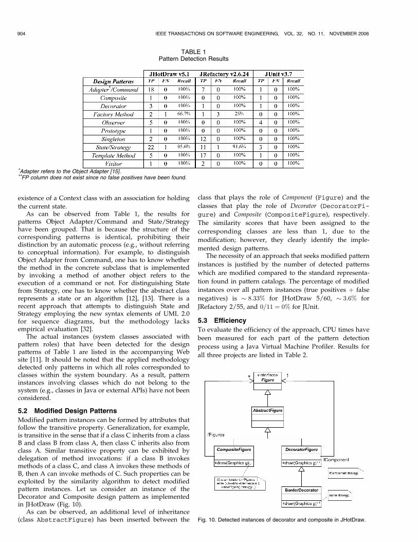
Modified pattern instances can be formed by attributes thatfollow the transitive property. Generalization, for example,is transitive in the sense that if a class C inherits from a classB and class B from class A, then class C inherits also fromclass A. Similar transitive property can be exhibited bydelegation of method invocations: if a class B invokesmethods of a class C, and class A invokes these methods ofB, then A can invoke methods of C. Such properties can beexploited by the similarity algorithm to detect modifiedpattern instances. Let us consider an instance of theDecorator and Composite design pattern as implementedin JHotDraw (Fig. 10).
As can be observed, an additional level of inheritance(class AbstractFigure) has been inserted between the
class that plays the role of Component (Figure) and the
classes that play the role of Decorator (DecoratorFi-
gure) and Composite (CompositeFigure), respectively.
The similarity scores that have been assigned to the
corresponding classes are less than 1, due to the
modification; however, they clearly identify the imple-
mented design patterns.The necessity of an approach that seeks modified pattern
instances is justified by the number of detected patterns
which are modified compared to the standard representa-
tion found in pattern catalogs. The percentage of modified
instances over all pattern instances (true positives þ false
negatives) is � 8:33% for JHotDraw 5/60, � 3:6% for
JRefactory 2/55, and 0=11 ¼ 0% for JUnit.
5.3 Efficiency
To evaluate the efficiency of the approach, CPU times have
been measured for each part of the pattern detection
process using a Java Virtual Machine Profiler. Results for
all three projects are listed in Table 2.
904 IEEE TRANSACTIONS ON SOFTWARE ENGINEERING, VOL. 32, NO. 11, NOVEMBER 2006
Fig. 10. Detected instances of decorator and composite in JHotDraw.
TABLE 1Pattern Detection Results
*Adapter refers to the Object Adapter [15].**FP column does not exist since no false positives have been found.

As can be observed, the pattern detection that consists in
the application of the similarity algorithm is the most
computationally intensive task of the whole process. In
most cases, the detection of a single pattern takes time
which is equal to that of all preprocessing steps. However,
the time required for the detection of a pattern by applying
the similarity algorithm to subsystems is significantly less
than the time required for identifying the pattern in the
entire system. Two conclusions can be drawn from the
results:
. The detection is slower for patterns with common
characteristics such as Adapter/Command and
State/Strategy. That is because there are fewer zero
attribute matrices that the algorithm can exploit to
skip the corresponding subsystems.
. The detection is slower for systems containing large
subsystems. For example, in JRefactory the group of
classes that do not belong in any inheritance
hierarchy (176 classes, 30 percent of the system
classes) is combined with all other hierarchies
forming extremely large subsystems. The CPU time
required for the convergence of the similarity
algorithm increases with the size of the matrix
describing the corresponding subsystem as well as
with the density of ones representing relationships
between pairs of classes.
Concerning memory requirements, the proposed meth-
odology consumes resources mainly for storing the adja-
cency matrices that represent the attributes of the system
under study. Results from a memory profiler are given in
Table 3.As expected, the memory requirements for the system
adjacency matrices are proportional to the square of the
number of classes in each system. One approach for
reducing the memory consumption of these matrices is
the employment of sparse matrix representation since, for
most of the attributes, these matrices are quite sparse.
6 IMPLEMENTATION
A tool has been implemented in Java that encompasses all
steps of the proposed methodology. The program employs
a Java bytecode manipulation framework [3], which enables
the detailed analysis of the system’s static structure. The
information retrieved is
. abstraction (whether a class is concrete, abstract, or
interface),. inheritance (parent class, implemented interfaces),. class attributes (type, visibility, and static members),. constructor signatures (parameter types),. method signatures (method name, return type,
parameter types, abstract or not),
TSANTALIS ET AL.: DESIGN PATTERN DETECTION USING SIMILARITY SCORING 905
TABLE 2CPU Times (in ms) for Pattern Detection Process
*1 Preprocessing is performed only once. Detection of additional patterns does not require the repetition of the preprocessing steps.*2 Measurements performed on Athlon XP 1400 MHz, 1 GB RAM.
TABLE 3Memory Requirements (in KB) and Percentage of Total Consumption
*1 Rest of memory is consumed mainly by GUI elements.

. method invocations (origin class and signature), and
. object instantiations.
The above information is used to extract more advanced
properties such as
. collection element type detection (type of elementscontained in a collection) and identification of iter-
ative method invocation on the elements of a
collection—used for detecting Observer and
Composite),. similar abstract method invocation (invocation of
an abstract method within a method having the
same signature—used for detecting Decorator and
Composite),. abstract method adaptation (invocation of another
class’ method in the implementation of an inherited
abstract method—used for detecting Adapter/
Command),. template method (invocation of an abstract class’
method in a method of the same class),. factory method (instantiation of an object in the
implementation of an inherited abstract method),. static self reference (private static attribute having as
type the class that it belongs to—used for detectingSingleton), and
. double or dual dispatch (used for detecting Visitor).
The extracted information is used to generate the matrices
that describe the system under study. In the current
implementation, pattern descriptions are hard-coded within
the program. However, the information required for
describing a design pattern (role names, adjacency matrices
for the attributes of interest, and the number of hierarchies
that the pattern involves) could be easily provided as
external input.
Once the system has been analyzed, the user can select a
design pattern to be detected from the graphical user
interface. Next, the similarity algorithm is applied as
described in the section on methodology and the detected
patterns are presented to the user without further human
intervention.
The tool and the source code can be downloaded from
the accompanying Web site [11].
7 THREATS TO VALIDITY—LIMITATIONS
The identification of the actual pattern instances was
based on the examination of external/internal documen-
tation and source code. However, manual code inspec-
tion by the authors could pose a threat to the validity of
the empirical evaluation, possibly affecting the number
of false negatives.
As already mentioned, there are patterns whose detec-
tion is based on the identification of a specific sequence of
actions. For this reason, the description of such patterns is
usually accompanied by sequence diagrams [15]. The
proposed approach does not employ dynamic information
and, if applied to such patterns, it will only reveal candidate
pattern instances. However, the proposed methodology can
be applied in combination with an approach that utilizes
dynamic information [17].
As already explained, the methodology relies on splitting
the system into subsystems of communicating hierarchies.
One scalability issue is that the time required for the
convergence of the similarity algorithm increases with the
size and density of the subsystem matrices. Moreover, since
sparse matrices are not employed for storing the entire
system representation, scaling up to systems with a very
large number of classes would lead to significant memory
requirements. The required memory increases quadratically
with the number of system classes.
In the case of a novel design pattern containing
characteristics that are covered by the already existing
attribute matrices, the only additional action for inserting
the pattern in the tool is to provide its description. On the
other hand, if a novel pattern has a characteristic that has
not been encountered earlier, one has to also provide an
implementation for constructing the system matrix for the
new attribute. However, as the number of supported
design patterns increases, the variety of covered structural
characteristics will get larger and the existing attribute
matrices are expected to become adequate for describing
most novel patterns.
8 RELATED WORK
A notion related to design patterns, before these appeared
in the literature, was the one of cliches. In the terminology of
Rich and Waters, the heads of the Programmer’s Apprentice
project [24], cliches were “commonly used combinations of
elements with familiar names.” This project developed an
intelligent assistant for building reusable and well-
structured software. A part of this project called the
Recognizer analyzed source code in various languages
and derived a representation in a form that could be
compared to the cliches stored in a knowledge base. We can
consider the Recognizer part of the Programmer’s Appren-
tice as an ascendant of today’s automated design pattern
detection techniques.
The first attempt to automatically detect design patterns
was performed by Brown [8]. In this work, Smalltalk code
was reverse-engineered in order to detect four well-known
patterns from the catalog by Gamma et al. [15]. The
algorithm was based on information retrieved from class
hierarchies, association and aggregation relationships, as
well as the messages exchanged between classes of the
system.Prechelt and Kramer [23] developed a system that could
identify a number of design patterns present in C++ source
code. OMT class diagrams representing the patterns were
inspected to build Prolog rules aiding their recognition.
Consequently, such an approach required the definition of
new Prolog rules in case a novel design pattern had to be
detected.
According to Wendehals [31], to efficiently detect the
design patterns present in a software system, a smart
combination of static and dynamic analysis is desirable.
906 IEEE TRANSACTIONS ON SOFTWARE ENGINEERING, VOL. 32, NO. 11, NOVEMBER 2006

In terms of UML notation, this requires the analysis of
class diagrams in order to recover the static information
and the examination of sequence or collaboration dia-
grams for the dynamic information. Heuzeroth et al. [17]
first apply static analysis to obtain a candidate set of
pattern instances and then perform dynamic analysis of
this set. However, this approach is heavily dependent on
the characteristics of each pattern: For every new pattern,
one has to come up with a specific algorithm for
computing the static candidates and then set up the rules
that will enable the dynamic analysis. This is prohibitive
for the development of an extensible automated design
pattern detection methodology.Antoniol et al. [2] developed a technique to identify
structural patterns in a system in order to examine how
useful a design pattern recovery tool could be in program
understanding and maintenance. Metrics are used in the
first stage to identify possible pattern candidates, while, in
the second stage, shortest path constraints are generated
from the shortest paths between roles in the patterns.
Finally, for some patterns where method calls are impor-
tant, delegation constraints are generated. The above three-
stage pattern recovery approach aims to reduce the
exploration space. The final pattern instances are extracted
based on structural information. Their technique has been
tested on small to medium size public domain systems. The
main disadvantage of the approach, as the authors also
note, is low precision (many false positives).
Balanyi and Ferenc [4] use the Columbus [14] reverse
engineering framework to extract an abstract semantic
graph and DPML (Design Pattern Markup Language) to
describe the characteristics of pattern roles. The pattern
mining algorithm tries to match roles present in the DPML
files with classes in the abstract semantic graphs. Search
space is reduced by filtering based on structural informa-
tion. The technique has been tested on four medium to large
size public domain projects. Their study reveals that the
more the description of the patterns is simplified, the more
false positives appear. Since the algorithm performs exact
matching, it is questionable whether the approach can
identify modified pattern versions.
A different solution is proposed by Costagliola et al. [10],
where a graphics format is used as an intermediate
representation. Design patterns are expressed in terms of
visual grammars and a design pattern library is built.
Patterns are detected in the system under study using a
visual language parsing technique and simultaneously
comparing the results of parsing with the existing library.
The main advantage of this approach is that the process can
be directly visualized; however, the approach has not been
evaluated on real systems since the tool does not integrate
with existing source-code to class-diagram extractors.
The aforementioned works are unable to detect modified
versions of patterns that deviate from their standard
representation. This poses a serious limitation on the
applicability of these techniques to real software systems.
Bergenti and Poggi [6] developed a method that
examines UML diagrams and proposes to the software
architect modifications to the design that lead to design
patterns. A part of this process is the automated detection of
design patterns in the system. The input to their tool is the
UML design (class and collaboration diagrams) of the
software system in XMI (XML Metadata Interchange)
format. Static and dynamic analysis is performed exploiting
a knowledge base consisting of Prolog rules that describe
the main characteristics of the patterns to obtain the final set
of pattern instances. For the introduction of novel design
patterns to the tool new Prolog rules have to be composed.
Furthermore, the authors do not provide any evaluation
results for real software systems.More recently, a method for detecting design patterns
through so-called “fingerprinting” has been proposed by
Gueheneuc et al. [16]. This approach reduces the search
space by identifying classes playing certain roles in design
motifs using metrics based on their external attributes. In
the next phase, actual pattern realizations are found with
structural matching. The efficiency of such an algorithm
depends strongly on the learning samples that compose the
repository of design motif roles.Albin-Amiot et al. [1] developed a technique that claims
to identify modified versions of design patterns. Their
pattern detection subsystem “PTIDEJ” examines the pro-
blem as a constraint satisfaction problem. This problem is
formulated by examining the pattern’s abstract model and
the source code under consideration. The set of the
variables as well as the constraints for the variables are
derived from the pattern’s abstract model while the domain
for the problem are the entities present in the source code of
the examined system. A tool called PALM is used to
identify in the source code microarchitectures that are
identical or similar to the microarchitecture defined by the
design pattern. The main drawback of the approach is that
in order to achieve the detection of a novel pattern, a new
abstract model (for the constraint satisfaction problem) has
to be embedded in the tool.
Tonella and Antoniol [27] used concept analysis based
on class relationships. Their application does not use any
knowledge base of design pattern representations. The
design patterns present in a system are inferred directly
from the system under study through finding recurrent
groups of classes. This approach has the advantage that it is
easily extensible since new patterns can be easily discov-
ered. One disadvantage of this approach is computational
complexity, which is reduced by considering up to order 3
class-context. That means that class sequences of length up
to 3 are considered to build a concept.
A different approach to automated design pattern
detection has been presented by Smith and Stotts [26],
based on the notion of elemental design patterns. Elemental
design patterns [25] are base concepts on which more
complex design patterns are built. The main power of an
approach based on the notion of elemental design patterns
is the ability to detect a design pattern after “refactorings”
[13] have been applied to it. At a first level, such elemental
design patterns are identified and at a second level, these
findings are composed to identify actual design patterns. In
TSANTALIS ET AL.: DESIGN PATTERN DETECTION USING SIMILARITY SCORING 907

order to represent directly relationships between objects,
methods, and fields, a formal language called rho-calculus
is used. The same language is used to formalize both the
design patterns as well as the system under consideration.
Next, an automated theorem prover is used to detect
instances of patterns in the system. However, it is not clear
which heuristic is used to combine the existing predicates in
order to achieve this result. Obviously, the computational
complexity of examining all the possible combinations, i.e.,
when no heuristic is applied, is prohibitive. The applic-
ability of this technique is presented with an illustration of
the steps required to detect the Decorator pattern in a small
author-made system.
Voka�c [29] tried to find a relation between the presence
of specific design patterns in software and the number of
defects. The reverse engineering tool “Understand for C++”
parses the source code and produces structural metadata,
which is stored in a database. Then, patterns are recovered
through database queries [30] that correspond to the
structural signature of each pattern. The recall (few false
negatives) and precision (few false positives) are quite
good. The validation of the technique has been performed
on a large commercial system. Recall has been evaluated on
a random sample of classes using statistical analysis.
9 CONCLUSIONS
The detection of design patterns in a software system, which
is an important task in the reengineering process, exploiting
only UML diagrams and designers’ experience, is very
difficult in the absence of automated assistance tools. The
proposed methodology fully automates the pattern detec-
tion process by extracting the actual instances in a system
for the patterns that the user is interested in. The main
contribution of the approach is the use of a similarity
algorithm, which has the inherent advantage of also
detecting patterns that appear in a form that deviates from
their standard representation. The application of the
proposed methodology in three open-source systems
demonstrated the accuracy and precision of the approach.
Few of the targeted patterns were missed (false negatives),
with no false positives.
REFERENCES
[1] H. Albin-Amiot, R. Cointre, Y.-G. Gueheneuc, and N. Jussien,“Instantiating and Detecting Design Patterns: Putting Bits andPieces Together,” Proc. 16th Ann. Conf. Automated Software Eng.(ASE ’01), pp. 166-173, Nov. 2001.
[2] G. Antoniol, G. Casazza, M. Di Penta, and R. Fiutem, “Object-Oriented Design Patterns Recovery,” J. Systems and Software,vol. 59, no. 2, pp. 181-196, 2001.
[3] ASM Home Page, http://asm.objectweb.org/, 2006.[4] Z. Balanyi and R. Ferenc, “Mining Design Patterns from C++
Source Code,” Proc. Int’l Conf. Software Maintenance, (ICSM ’03),pp. 305-314, Sept. 2003.
[5] E. Bengoetxea, “Inexact Graph Matching Using Estimation ofDistribution Algorithms,” PhD thesis, Ecole Nationale Superieuredes Telecommunications, France, Dec. 2002.
[6] F. Bergenti and A. Poggi, “Improving UML Designs UsingAutomatic Design Pattern Detection,” Proc. 12th Int’l Conf.Software Eng. and Knowledge Eng. (SEKE ’00), July 2000.
[7] V.D. Blondel, A. Gajardo, M. Heymans, P. Senellart, and P. VanDooren, “A Measure of Similarity between Graph Vertices:Applications to Synonym Extraction and Web Searching,” SIAMRev., vol. 46, no. 4, pp. 647-666, 2004.
[8] K. Brown, “Design Reverse-Engineering and Automated DesignPattern Detection in Smalltalk,” Technical Report TR-96-07, Dept.of Computer Science, North Carolina State Univ., 1996.
[9] D.J. Cook and L.B. Holder, “Substructure Discovery UsingMinimum Description Length and Background Knowledge,”J. Artificial Intelligence Research, vol. 1, pp. 231-255, Feb. 1994.
[10] G. Costagliola, A. De Lucia, V. Deufemia, C. Gravino, and M. Risi,“Design Pattern Recovery by Visual Language Parsing,” Proc.Ninth European Conf. Software Maintainance and Reeng. (CSMR ’05),pp. 102-111, Mar. 2005.
[11] Design Pattern Detection, http://java.uom.gr/~nikos/pattern-detection.html, 2006.
[12] R. Ferenc, A. Beszedes, L. Fulop, and J. Lele, “Design PatternMining Enhanced by Machine Learning,” Proc. 21st IEEE Int’lConf. Software Maintenance (ICSM ’05), pp. 295-304, Sept. 2005.
[13] M. Fowler, Refactoring: Improving the Design of Existing Code.Addison Wesley, 1999.
[14] FrontEndART Ltd., http://www.frontendart.com. 2006.[15] E. Gamma, R. Helm, R. Johnson, and J. Vlissides, Design Patterns:
Elements of Reusable Object-Oriented Software. Addison Wesley,1995.
[16] Y.-G. Gueheneuc, H. Sahraoui, and F. Zaidi, “FingerprintingDesign Patterns,” Proc. 11th Working Conf. Reverse Eng. (WCRE’04),Nov. 2004.
[17] D. Heuzeroth, T. Holl, G. Hogstrom, and W. Lowe, “AutomaticDesign Pattern Detection,” Proc. 11th IEEE Int’l Workshop ProgramComprehension (IWPC ’03), May 2003.
[18] JHotDraw Start Page, http://www.jhotdraw.org, 2006.[19] JRefactory, http://jrefactory.sourceforge.net/, 2006.[20] JUnit, http://www.junit.org, 2006.[21] J.M. Kleinberg, “Authoritative Sources in a Hyperlinked Environ-
ment,” J. ACM, vol. 46, no. 5, pp. 604-632, Sept. 1999.[22] B.T. Messmer and H. Bunke, “Efficient Subgraph Isomorphism
Detection: A Decomposition Approach,” IEEE Trans. Knowledgeand Data Eng., vol. 12, no. 2, pp. 307-323, Mar./Apr. 2000.
[23] L. Prechelt and C. Kramer, “Functionality versus Practicality:Employing Existing Tools for Recovering Structural DesignPatterns,” J. Universal Computer Science, vol. 4, no. 12, pp. 866-882, Dec. 1998.
[24] C. Rich and R. Waters, “The Programmer’s Apprentice: AResearch Overview,” IEEE Computer, vol. 21, no. 11, pp. 11-24,Nov. 1998.
[25] J.M. Smith, “An Elemental Design Pattern Catalog,” TechnicalReport TR-02-040, Dept. of Computer Science, Univ. of NorthCarolina, Oct. 2002.
[26] J.M. Smith and D. Stotts, “SPQR: Flexible Automated DesignPattern Extraction from Source Code,” Proc. 18th IEEE Int’l Conf.Automated Software Eng. (ASE ’03), Oct. 2003.
[27] P. Tonella and G. Antoniol, “Object Oriented Design PatternInference,” Proc. IEEE Conf. Software Maintenance (ICSM ’99),pp. 230-238, 1999.
[28] J.R. Ullman, “An Algorithm for Subgraph Isomorphism,” J. ACM,vol. 23, no. 1, pp. 31-42, Jan. 1976.
[29] M. Voka�c, “Defect Frequency and Design Patterns: An EmpiricalStudy of Industrial Code,” IEEE Trans. Software Eng., vol. 30,no. 12, pp. 904-917, Dec. 2004.
[30] M. Voka�c, “An Efficient Tool for Recovering Design Patterns fromC++ Code,” J. Object Technology, vol. 2, no. 2, July/Aug. 2005.
[31] L. Wendehals, “Improving Design Pattern Instance Recognitionby Dynamic Analysis,” Proc. Workshop Dynamic Analysis (WODA’03), May 2003.
[32] L. Wendehals, “Specifying Patterns for Dynamic Pattern InstanceRecognition with UML 2.0 Sequence Diagrams,” Proc. SixthWorkshop Software Reeng. (WSR ’04), pp. 63-64, May 2004.
908 IEEE TRANSACTIONS ON SOFTWARE ENGINEERING, VOL. 32, NO. 11, NOVEMBER 2006
Nikolaos Tsantalis received the BS and MSdegrees in applied informatics from the Univer-sity of Macedonia in 2004 and 2006, respec-tively. He is a PhD candidate with theDepartment of Applied Informatics at the Uni-versity of Macedonia, Greece. His researchfocuses on design patterns, refactorings, andobject-oriented quality metrics.
Alexander Chatzigeorgiou received the diplo-ma in electrical engineering and the PhD degreein computer science from the Aristotle Universityof Thessaloniki, Greece, in 1996 and 2000,respectively. He is a lecturer in softwareengineering in the Department of Applied Infor-matics at the University of Macedonia, Thessa-loniki, Greece. From 1997 to 1999 he was withIntracom SA Greece, as a telecommunicationssoftware designer. His research interests are in
software metrics, object-oriented design and low-power hardware/software design. He is a member of the IEEE Computer Society.
George Stephanides is an assistant professorin the Department of Applied Informatics, Uni-versity of Macedonia, Thessaloniki, Greece. Heholds a PhD degree in applied mathematics fromthe University of Macedonia. His current re-search and development activities are in theapplications of mathematical programming, se-curity and cryptography, and application specificsoftware. He is a member of the IEEE ComputerSociety.
Spyros T. Halkidis received the BS degree andthe MS degree in computer science from theUniversity of Crete, Greece, in 1996 and 1998,respectively. He also received the MBA degreefrom the University of Macedonia, Greece, in2000. Since 2003, he is a PhD candidate in theDepartment of Applied Informatics at the Uni-versity of Macedonia, Thessaloniki, Greece. Hiscurrent research interests include software en-gineering, secure software, and security patterns.
. For more information on this or any other computing topic,please visit our Digital Library at www.computer.org/publications/dlib.
TSANTALIS ET AL.: DESIGN PATTERN DETECTION USING SIMILARITY SCORING 909