Design optimization of high frequency op amp using 32 nm CNFET
61
Final Project Report Smart Phone FTP Client Project Supervisor <<Usman Waheed >> Submitted By <<F120216DA3>> <<Rabia Mirza>> <<mc110403579>> Software Projects & Research Section,
-
Upload
independent -
Category
Documents
-
view
1 -
download
0
Transcript of Design optimization of high frequency op amp using 32 nm CNFET

Final Project Report
Smart Phone FTP Client
Project Supervisor<<Usman Waheed >>
Submitted By
<<F120216DA3>>
<<Rabia Mirza>> <<mc110403579>>
Software Projects & Research Section,

Department of Computer Sciences,Virtual University of Pakistan
CERTIFICATE
This is to certify that <<Rabia Mirza>> (<<mc110403579>>) has worked on and completed their Software Project at Software & Research Projects Section, Department of Computer Sciences, Virtual University of Pakistan in partial fulfillment of the requirement for the degree of BS in Computer Sciences under my guidance and supervision.
In our opinion, it is satisfactory and up to the mark and therefore fulfills the requirements of BS in Computer Sciences.
Supervisor / Internal Examiner
<<Usman Waheed>>Supervisor,Software Projects & Research Section,Department of Computer SciencesVirtual University of Pakistan
___________________(Signature)
External Examiner/Subject Specialist<<External Supervisor Name>>

___________________(Signature)
Accepted By:
_____________ (For office
use)
EXORDIUM
In the name of Allah, theCompassionate, the Merciful.
Praise be to Allah, Lord of Creation,The Compassionate, the Merciful,
King of Judgment-day!
You alone we worship, and to You alonewe pray for help,
Guide us to the straight path
The path of those who You have favored,
Not of those who have incurred Yourwrath,
Nor of those who have gone astray.


DEDICATION
I dedicate this report to my supervisorMuhammad (Usman Waheed), who have
always been here for me, and have neverdoubted my dreams, no matter how crazythey might be. Also to the people whohelped me in making this project and
who find themselves at a place in lifewhere the question of why seemsunanswerable, you are not alone.

ACKNOWLEDGEMENT
It is incumbent upon us to express our fervent gratitudeto almighty ALLAH the most compassionate and merciful forgiving us the courage to achieve this task in the field ofsoftware development study.
We are indeed humbly grateful to the Prophet HAZRATMUHAMMAD (peace be upon him) who is forever a source ofguidance and idea for all mankind.
Any attempt at any level can't be satisfactorily completedwithout the support and guidance of learned people. Wewould like to express our immense gratitude to ourinstructor for his constant support and motivation thathas encouraged us to come up with this project.
We are also thankful to our families, friends who haverendered their whole hearted support at all times for thesuccessful completion of this project Goods TransportManagement System.
May GOD almighty Allah infuse us, with the energy tofulfill their noble aspirations and expectations and tofurther edify our competence!

PREFACE
In the preface of this final project report we would like to provide a brief introduction of Smart Phone FTP Client final report. This final report of the project depicts allthe phases & steps which we have taken to complete this project.
What is included?In order to complete this project we have followed the Java language guidelines.
The language used
For the completion of this project we use Java Language and ADT frame work
You will need
You will need a Android phone and FTP server.

TABLE OF CONTENTS
CHAPTER NO. 1GATHERING & ANALYZING INFO................................9
1.1 INTRODUCTION
1.2 PURPOSE
1.3 SCOPE
1.4 FUNCTIONAL AND NON FUNCTIONAL REQUIREMENTS
1.4.1 Functional Requirements
1.4.2 Non Functional Requirements
1.5 USE CASE DIAGRAM(S)
1.6 USAGE SCENARIOS
CHAPTER NO. 2PLANNING THE PROJECT.....................................162.1 INTRODUCTION
2.2 METHODOLOGY
2.3 AVAILABLE METHODOLOGIES
2.4 CHOSEN METHODOLOGY
2.5 REASONS FOR CHOSEN METHODOLOGY
2.6 WORK PLAN

CHAPTER NO. 3DESIGNING THE PROJECT....................................29
3.1 INTRODUCTION3.2 OVERVIEW OF PURPOSED SYSTEM
3.3 CONTEXT DIAGRAM
3.4 DYNAMIC MODEL: SEQUENCE DIAGRAMS
3.5 OBJECT MODEL/LOGICAL MODEL: CLASS DIAGRAM
3.6 DEPLOYMENT MODEL (DEPLOYMENT DIAGRAM)
3.7 DATABASE MODEL (DATABASE DIAGRAM)
3.8 GRAPHICAL USER INTERFACES
CHAPTER NO.4DEVELOPMENT..............................................424.1 DEVELOPMENT PLAN (ARCHITECTURE DIAGRAM)
CHAPTER NO.5DEPLOYMENT...............................................455.1 DEPLOYMENT PLAN (DEPLOYMENT DIAGRAM)

CHAPTER 1Gathering & Analyzing Info

1.1 Introduction:
In this Phase all the requirements are gathered and analysis for a batter software development which should meet customer requirements and lead to ultimate successfulcompletion of this project.
1.2 Purpose:
The main purpose of this phase is gather exact information and material which is essential for successful completion of this project.
1.3 Scope of Project:
The tool Android has a great scope now-a-days. As it is mobile application and so due to a lot of usage of mobile the scope for mobile applications also increases. There are many benefits of using Android. Android is the best mobile operating system. The FTP client comes with all basic and advanced features that anyFTP client must have, but the main benefit of using this application on our Android, is that we need not be tech expert to use this. It has simple yet easy to use user

interface that allow us to easily interact with an FTP server from our android mobile or our tablet. We can send files, download or upload files, can delete edit or createnew files and that all from this single FTP app. Moreover,this one is free to download and use and can be got from Google.FTP client is simple and useful for android and it offer all basic features like file sharing, downloading, uploading, editing etc. from our Android based Smartphone or tablet.Smart phones are everywhere, and people all over the worldare using them because of the many useful and amazing features they have that people love. People use smart phones for their daily work because Smart phones have loads of advantages over a PC or Laptop, portability beinga major one. Smartphone based applications let us access our data no matter where we are. We can perform every taskwith a smart phone in our pocket that we would do with ourlaptop or computer.
1.4 Functional and non Functional Requirements:
1.4.1 Functional Requirements:As we know Functional requirements defines the internal working of the system, i.e. calculations, technical details, data manipulations and processing and other specific functionality that shows how the use cases are tobe satisfied.
The important Functional Requirements for the above mentioned software project are given below.
System will facilitate users to access any FTPserver.
System will facilitate the anonymous user to sign up. System will save login credentials for different FTP
servers in mobile using encrypted data storage.

System will facilitate to upload any file from mobiledevice to specified folder.
System will be able show confirmation options. System will have the ability to download any file
form FTP server to mobile phone. System will facilitate normal file operations: Copy,
Move, Delete, Rename etc.
1.4.2Non-Functional Requirements:
Non functional requirements impose constraints on the design or implementation (such as performance requirements, quality standards or design constraints. Non-functional requirements are often called qualities of a system
The Non Functional Requirements for the above mentioned software project are given below.
Accessibility Backup
Configuration management
Efficiency (resource consumption for given load)
Effectiveness (resulting performance in relation to effort)
Failure management
Legal and licensing issues or patent-infringement-avoid ability
Performance / response time (performance engineering)
Privacy
Portability
Quality (e.g. faults discovered, faults delivered, fault removal efficacy)
Recovery / recoverability (e.g. mean time to recovery)
Reliability (e.g. mean time between failures )
Response time
Robustness
Security
1.5 Use Case Diagram(s):
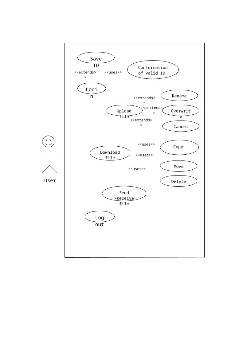
User
Login
Upload file
Copy Download file
Save ID
Log out
Conformation of valid ID
Send /Receive file
<<extends>>
<<uses>>
Rename
Overwrite
Cancel
<<extends>><<extends>
><<extends>
>
Move
Delete
<<uses>>
<<uses>>
<<uses>>

1.6 Usage Scenarios:
Use Case Title LoginAbbreviated Title Login
Use Case ID UC0001
Actions •User goes to login panel first.• And provide the Id and Password to the system.• After Verifying the User id and password user gets log in.
Description
By logging in the account the user can
• access the control panel.
• update profiles.
• carry out authorized activities.
• Send or receive any file.
Alternative Paths NonePre-Condition
User must have a valid login id and password.
Post Condition User is logged in successfully and views its allowed account/options. User may also be denied in case of invalid login attempt.
Author Authorize User that has access to password.
ExceptionId and/or password is incorrect.
User has selected invalid branch name/id.

Use Case Title Send / Receive FileAbbreviated Title Send / Receive File
Use Case ID UC0002
Actions • User goes to login panel first.• And provide the Id and Password to the system.• After Verifying the User id and password user gets log in.After login user can send or receive file.
Description
After logging in the account the user
can
• send the file.
• receive the file.
Alternative Paths NonePre-Condition
User must have a valid login id and password.
Post Condition User is logged in successfully and is allowed to send/receive file. User may also be denied in case of invalid login attempt.
Author Authorize User that has access to password.
ExceptionId and/or password is incorrect.
User has selected invalid branch name/id.

Use Case Title Update FileAbbreviated Title Update File
Use Case ID UC0003
Actions • User goes to login panel first.• And provide the Id and Password to the
system.• After Verifying the User id and
password user gets login.• After login user can update file.
Description
After logging in the account the user
can
• Change the file.
• Rename or delete the file.
Overwrite the file.
Alternative Paths NonePre-Condition
User must have a valid login id and password.
Post Condition User is logged in successfully and is allowed to update the file. User may also be denied in case of invalid login attempt.
Author Authorize User that has access to password.
ExceptionId and/or password is incorrect.
User has selected invalid branch name/id.

Use Case Title Download FileAbbreviated Title Download File
Use Case ID UC0004
Actions • User goes to login panel first• And provide the Id and Password to the system• After Verifying the User id and password user gets log inAfter login user can download file
Description
After logging in the account the user
can
• Download any file.
• Copy/move any file
• Rename any file
Alternative Paths NonePre-Condition
User must have a valid login id and password.
Post Condition User is logged in successfully and is allowed to download the file. User may also be denied in case of invalid login attempt.
Author Authorize User that has access to password.
ExceptionId and/or password is incorrect.

User has selected invalid branch name/id.
CHAPTER 2Planning the Project

2.1 Introduction of the Planning Phase
Software project management covers many aspects ofsoftware including scheduling, cost control,budget management, resources allocation, qualitymanagement and documentation or administrationsystem that are used to deal with the complexityof large projects. Planning phase is veryimportant in development of a project. There arevarious phases in planning of project like scopeplanning, resources planning, budget andconfiguration etc. the plans created help tomanage time, quality, cost risk and other issuesarising during the life cycle of project. It alsohelps to complete the project on time and withinschedule. In this document we are covering thefollowings:
1.Definition and scope of the project.2.Gathering requirement and analysis.3.Preliminary Design 4.Detailed design5.Code 6.Testing

7.Implementation 8.Maintenance
Advantages of planning in project:
Project planning is very beneficial in developinga project. It helps a lot in creation of asuccessful project. It saves time and money andguarantees a more successful outcome. It madepossible to achieve agreed goals, coordinatingmultiple resources within time and costconstrains. Here are some major benefits ofplanning.
1.It enables us to use resources moreefficiently.
2.It provides the mechanism to create projectmatrices to measure results and optimize theproduct development process.
3.Team of developer knows well what is going onand what is expected from them.
4.Client will be satisfied with organization andappreciate it.
5.It made easy to present a project and itsprogress to the upper management and alsopresent a clear view of budget, resources andperformance requirements.
6.Planning facilitates communication and madeexpectations clear.
7.It made possible on time working during lifecycle of project.
8.It clears the task dependencies and made iteasy to manage them, that help to avoid thetraffic jam during processing on a project.
9.It helps to hit the important milestones dueto being planned.

10. Careful planning includes the riskassessment and also set measures to managethem.
11. It makes the objectives clear that guidesto the right path to the destination andproduction of a successful project.
2.2 Methodologies
A software development methodology or systemdevelopment methodology in software engineering isa framework that is used to structure, plan, andcontrol the process of developing an informationsystem. Some are as follows:

A wide variety of such frameworks have evolvedover the years, each with its own recognizedstrengths and weaknesses. One system developmentmethodology is not necessarily suitable for use byall projects. Each of the available methodologiesis best suited to specific kinds of projects,based on various technical, organizational,project and team considerations.
The framework of a software development methodology consists of:
A software development philosophy with the approach or approaches of the software development process
Multiple tools, models and methods, to assist in the software development process.
These frameworks are often bound to some kind of organization, which further develops, supports theuse, and promotes the methodology. The methodologyis often documented in some kind of formal documentation.
2.3 Existing Methodologies
We have various methodologies in softwaredevelopment. Some of the most commonly usedmethodologies are:
Waterfall Methodology:
This is also known as linear sequential model. Itsuggests a systematic, sequential approach tosoftware development that begins at the system

level and progresses through the analysis, design,coding, testing, and maintenance. In the customarywaterfall methodology, first comes the analysisstage, then the design stage, pursued by theimplementation stage, with testing implementationthe process. The team that does each phase isdifferent and there may be an organizationconclusion point at each phase alteration. Thismethodology is called the waterfall methodologybecause each phase flows obviously into the nextphase like water in excess of a series of falls.
Water fall method is common term that is based ona sequential software development where we finddevelopment as a waterfall flowing progressivelydownstream, through the stages of designdevelopment. Software model is sequential softwaredevelopment process in which progress is seen assteadily downwards through the phases ofconception, Analysis, Design, Initiation,Construction, Maintenance and Testing. Waterfalldevelopment model has its origins in theconstruction industries, manufacturing industriesand in highly structured physical environments inwhich after-the-fact changes are prohibitively

costly, if not impossible. At the time, no formalsoftware development methodologies were existedand this hardware-oriented model was adapted tosoftware development.
Real projects rarely follow the sequential flowthat the model proposes. In general these phasesoverlap and feed information to each other. Hencethere should be an element of iteration andfeedback. A mistake caught any stage should bereferred back to the source and all the subsequentstages need to be revisited and correspondingdocuments should be updated accordingly. Thisfeedback path is shown in the following diagram.
Because of the costs of producing and approvingdocuments, iterations are costly and requiresignificant rework.

The Waterfall Model is a documentation-drivenmodel. It therefore generates complete andcomprehensive documentation and hence makes themaintenance task much easier. It however suffersfrom the fact that the client feedback is receivedwhen the product is finally delivered and henceany errors in the requirement specification arenot discovered until the product is sent to theclient after completion. This therefore has majortime and cost related consequences.
Spiral Methodology:
This model was developed by Barry Boehm. The mainidea of this model is to avert risk as there isalways an element of risk in development ofsoftware. Spiral model is also recognized as thespiral lifecycle model. It is such a systemdevelopment lifecycle (SDLC) model used in IT

(information technology). This development modelcombines the features of prototyping model and thewaterfall model. This model is preferential forlarge, expensive, and complex projects. In itssimplified form, the Spiral Model is Waterfallmodel plus risk analysis. In this case each stageis preceded by identification of alternatives andrisk analysis and is then followed by evaluationand planning for the next phase. If risks cannotbe resolved, project is immediately terminated.This is depicted in the following diagram:
As can be seen, a Spiral Model has two dimensions.Radial dimension represents the cumulative cost to

date and the angular dimension represents theprogress through the spiral. Each phase begins bydetermining objectives of that phase and at eachphase a new process model may be followed.
A full version of the Spiral Model is shown below:
The main strength of the Spiral Model comes fromthe fact that it is very sensitive to the risk.Because of the spiral nature of development it iseasy to judge how much to test and there is nodistinction between development and maintenance.It however can only be used for large-scalesoftware development and that too for internal(in-house) software only.
Agile Software Development

It is a group of methodologies based on iterative development where requirements and solution evolvethrough collaboration between cross functional teams. It generally promotes a disciplined projectmanagement process that encourages frequent inspection and adaptation. A set of best engineering practices intended to allow for a rapid delivery of high quality software.
In agile methods task is divided in small segmentsthat need minimal planning and don’t involve long term planning directly. Iterations are small time frames that involve a complete team work. This minimizes the overall risk and let the project adapt to changes quickly. Multiple iterations may b required to release a product or new feature.
“Agile Development” is an umbrella term forseveral iterative and incremental software

development methodologies. The most popular agilemethodologies include Extreme Programming (XP),Scrum, Crystal, Dynamic Systems Development Method(DSDM), Lean Development, and Feature-DrivenDevelopment (FDD).
While each of the agile methods is unique inits specific approach, they all share a commonvision and core values. They all fundamentallyincorporate iteration and the continuous feedbackthat it provides to successively refine anddeliver a software system. They all involve incontinuous planning, continuous testing,continuous integration, and other forms ofcontinuous evolution of both the project and thesoftware.
V-model
The V-model is a software development process thatis also applicable to hardware developmentconsists of a number of phases. The VerificationPhases are on the left hand side of the V, theCoding Phase is at the bottom of the V and theValidation Phases are on the right hand side ofthe V. the horizontal and vertical axis representtime or project completeness and level ofabstraction.

The V-model deploys a well-structured method in which each phase can be implemented by the detailed documentation of the previous phase The Vmodel provides the assistance on how to implement an activity. It is project independent.
Verification phases include Requirements analysis, System Design, Architecture Design, Module Design
The coding phases are at the bottom. Validation phases are Unit Testing,
Integration Testing , System Testing , User Acceptance Testing.
The V model is commonly used to identify the relationship between the development and testing phases, and to ensure that appropriate quality assurance and testing takes place throughout the project lifecycle.

Gantt charts:
Gantt charts show task and schedule information. The tasks are usually numbered and listed vertically. A bar shows the starting date and projected completion date of each task
Chart Example.
Gantt Charts are a way to graphically showprogress of a project. Management of a project ismade easier if it is viewed as small manageableitems where the dependencies are visuallyillustrated, parallel processes are discovered,the overall processing time determined andprogress tracked. The task of a project can bequite complex and dependent on each other with aproject management tool, such as Gantt chart, allsubtasks of a task can be viewed graphically.
2.4 Adopted Methodology

I selected a combination of methodologies thathave benefits of both the waterfall and spiralmethodologies. As life cycle of a project is acontinue process so it needs a regular monitoring.I selected the combination to get the morebenefits of both methodologies.
Spiral methodology is already a combination ofprototyping, waterfall and risk analysis, so itscombination with other methodology enhances thebenefits. In waterfall methodology each phase ofproject is completed and tested and then new phasestarts that make easy to avoid the risks and alsotheir management. In spiral model it is easy tojudge how much is to test due to spiral nature ofdevelopment.
VU PROCESS MODEL

2.5 Reasons for choosing the Methodology
VU process model combines the features ofdifferent methodologies like spiral, waterfall andprototyping model. That’s why I choose this forour project lifecycle.
Initially each software project or projectfrom any other era of our daily life makes easierif there is any kind of prototype model exists.During the running life of development oneapplication must be designed using the waterfallfeatures and then adopting the features of spiralmodel to overcome on errors, updates andmodification. Because after a prototype modelthere may be some changes, updates possible whenthis model takes an overview by the management andend user. The development cycle may proceeds orrevises after completing any cycle to meet thesechanges.
As per “Smartphone FTP Client” perspectives,at initial stage the waterfall become much helpfulto make a simple flow and work of the project.After a prototype model when the software comesinto being, the changes at that level can beminimized and point out and also overcomes bySpiral model features.

2.6 Work Plan (Use MS Project to create
Schedule/Work Plan)
ID Task Nam e
1 SRS Docum ent2 Methodology & W ork Plan3 Design Doc.14 Design Doc.25 Developm ent and Final Project Report
F S S M T W T F S S M T W T F S S M T W T F S S M T W T F S S M T W T F S S M T W T F S S M T WNov 11, '12 Nov 18, '12 Nov 25, '12 Dec 2, '12 Dec 9, '12 Dec 16, '12 Dec 23, '12 Dec 30, '12

CHAPTER 3Designing the Project

3.1 Introduction (of analysis and design
phase)
Table 1.1: The Analysis Phase: What does the system do?
Phase Deliverable
Analysis
Requirements Document Domain Ontology
- Things- Actions- States
Typical Scenarios Atypical
Scenarios

“ The analysis phase defines the requirements ofthe system, Independent of how these requirementswill be accomplished. This Phase defines theproblem that the customer is trying to solve. TheDeliverable result at the end of this phase is arequirement document. Ideally, this documentstates in a clear and precise fashion what is toBe built. This analysis represents the ``what''phase. The requirement Document tries to capturethe requirements from the customer's perspectiveBy defining goals and interactions at a levelremoved from the Implementation details. “
The requirement document may be expressed ina formal language based on mathematical logic.Traditionally, the requirement document is writtenin English or another written language. Therequirement document does not specify thearchitectural or implementation details, butspecifies information at the higher level ofdescription. The problem statement, the customer'sexpectations, and the criteria for success areexamples of high-level descriptions. There is afuzzy line between high-level descriptions andlow-level details. Sometimes, if an exactengineering detail needs to be specified, thisdetail will also appear in the requirementdocument. This is the exception and should not bethe rule.
These exceptions occur for many reasonsincluding maintaining the consistency with otherestablished systems, availability of particularoptions, customer's demands, and to establish, atthe requirement level, a particular architecturevision. An example of a low-level detail thatmight appear in the requirement document is the

usage of a particular vendor's product line, orthe usage of some accepted computer industrystandard, or a constraint on the image size of theapplication. There is a fundamental conflictbetween high levels and low levels of detail. Therequirement document states what the system shouldaccomplish, independent of many of the details.The discovery process used in establishing therequirements during the analysis phase is bestdescribed as a refinement process than as alevels-of-detail process. Top-down and bottom-upapproaches force a greater distinction betweenhigh levels and low levels of detail. Interactiveapproaches lead to the refinement of thosedetails.
Traditionally, the requirement document describesthe things in the system and the actions that canbe done on these things. Things might be expressedas objects in an object-based technology wheredata and algorithms are hidden behindhierarchical-polymorphic methods. Alternatively,things might be expressed as services accessingdatabases in a functional approach where data is afundamentally different concept than functions. Ingeneral, the description of things in the systemcan be much more general and not confined to aparticular technology. In a more general sense,this document describes the ontology that is thenoun phrases and the verb phrases that will becomethe guidelines for defining the applicationspecific protocol.
The requirement descriptions of the things in thesystem and their actions does not imply anarchitecture design rather a description of theartifacts of the system and how they behave, from

the customer's perspective. Later, in the designphase, these requirement descriptions are mappedinto computer science based primitives, such aslists, stacks, trees, graphs, algorithms, and datastructures.
The description of the abstraction of the nounphrases and the verb phrases are not bound to theuse of a written human language. Most writtenhuman languages are too vague to capture theprecision necessary to build a system. Alternativedescriptive mechanisms based on mathematical logicare sometimes more suitable but much moredifficult to accomplish. Mathematical logicprovides a scientific foundation for preciselyexpressing information. However, frequently in thereal world, a precise description is notattainable.
Again the requirement document should state in aclear and precise fashion what is to be built. Thedefinitive mechanism to author such a document,either formally or informally, has yet to bedeveloped, although reasonable success has beenachieved with existing methods including CASEtools and tools based on mathematical logic.

Later, in the design phase, the very importantdecomposition of the problem leads to thedevelopment of data structures and algorithms. Afunctional decomposition for a distributedenvironment leads to a natural split of the datastructures and algorithms. Examples includedistributed client-server systems, where adatabase holds the data in a server while thealgorithms manipulating the data reside on theclient. An object-based decomposition leads to anatural joining of data structures and algorithmsforming objects with methods. The requirementdocuments should be independent of thedecomposition technique.
The analysis team develops the requirementdocument, which talks about things and actions onthings. This document should also include states,events, typical scenarios of usage, andatypical scenarios of usage. The definitionsof things, actions, states, typicalscenarios, and atypical scenarios followthis section.
Table 1.2: The Design Phase: What arethe plans?
Phase Deliverable
Design
Architecture Document
Implementation Plan
Critical Priority Analysis

Performance Analysis Test Plan
In the design phase the architecture isestablished. This phase starts with therequirement document delivered by the requirementphase and maps the requirements into architecture.
The architecture defines thecomponents, their interfaces and behaviors. Thedeliverable design document is the architecture.The design document describes a plan to implementthe requirements. This phase represents the``how'' phase. Details on computer programminglanguages and environments, machines, packages,application architecture, distributed architecturelayering, memory size, platform, algorithms, datastructures, global type definitions, interfaces,and many other engineering details areestablished. The design may include the usage ofexisting components.
The architectural team can now expand upon theinformation established in the requirementdocument. Using the typical and atypical scenariosprovided from the requirement document,performance trade-offs can be accomplished as wellas complexity of implementation trade-offs.
Obviously, if an action is done many times, itneeds to be done correctly and efficiently. Aseldom used action needs to be implementedcorrectly, but it is not obvious what level ofperformance is required. The requirement documentmust guide this decision process. An example of aseldom used action which must be done with high

performance is the emergency shutdown of a nuclearreactor.
Analyzing the trade-offs of necessary complexityallows for many things to remain simple which, inturn, will eventually lead to a higher qualityproduct. The architecture team also converts thetypical scenarios into a test plan.
In our approach, the team, given a completerequirement document, must also indicate criticalpriorities for the implementation team. A criticalimplementation priority leads to a task that hasto be done right. If it fails, the product fails.If it succeeds, the product might succeed. At thevery least, the confidence level of the teamproducing a successful product will increase. Thiswill keep the implementation team focused. Exactlyhow this information is conveyed is a skill basedon experience more than a science based onfundamental foundations.
The importance of priority setting will becomeevident in the theory presented later.
3.2 Overview (of proposed system)
This will be a mobile FTP application. Theapplication will facilitate users to access anyFTP server (with id and password). The applicationwill use Wi-Fi or Packet Data (or any other sourceof internet in mobile phones).It will be a full featured FTP client havingfollowing features:

Login:This application will provide facility to login into ftp server by providing a valid username andpassword. Each user can save his Id. Save logincredentials for different FTP servers in mobileusing encrypted data storage, so that users do nothave to login explicitly each time on anyparticular FTP server.
Directory structure:A directory structure is the way an operating system's file system and its files are displayed to the user. Files are typically displayed in a Hierarchical tree structure. This application provides the facility to list the directory structure in a tree or similar structure.
Upload File:Using this application the user can upload file from mobile device to specified folder of the FTP server. It will show uploading procedure using progress bar or similar control that displays the uploading of files in percentage as 100% will indicate the successful uploading of file or if the upload is stop and canceled it will display a message.
Download file:Using this application the user can download any file form FTP server to mobile phone. While downloading it will show different confirmation options like Overwrite, Rename, And Cancel if a file with same name already exists on FTP server.
File operations:

This application will facilitate different file operations such as Copy, Move, Delete, Rename etc,in FTP server. Using the operation user can copy afile from one folder to other or can also move it to the other folder as well. User can delete the files which are of no use any more. User can also rename the file whenever he wants.
3.3 Context Diagram:
3.4 Dynamic Model: Sequence Diagrams
login
Smartphone ftp Client
DataUser
Ftp server
Upload data
Download data
Login
File operations
Conformation of data changes
Access to data
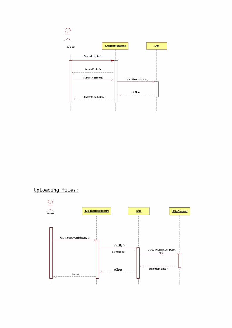
Uploading files:

Downloading files:
Send/Receive files:

3.5 Object Model/Logical Model: Class Diagram

3.6 Deployment Model (Deployment Diagram)

3.7 Database Model (Database Diagram)
3.8 Graphical User Interfaces:


CHAPTER 4Development

4.1 Development plan (Architecture Diagram):
4.1.1 Hardware Design Architecture Diagram:

User InterfacePresentation Layer
Processes of Business
Repository for Enterprise Services
Integration
System at Backend
Presentation Layer
Business Service Layer
Business Objects Layer
Data Access Layer
Persistence Layer
4.1.2 Software Design Architecture Diagram:

PresentationView Components
ApplicationController Components
ServiceDetermination/Implementation
Data AccessRepository
Changes/Implementation
SQL-Server
LoggingException HandlingFree Day and time slot determination etc…

CHAPTER 5Deployment

5.1 Deployment Plan (Deployment Diagram)

REFERENCES
(i) Software Engineering I(ii) Software Engineering II(iii) Software project management

APPENDIX