Design of visible-light photocatalysts by coupling of narrow bandgap semiconductors and TiO2: Effect...
9
1822 Catal. Sci. Technol., 2013, 3, 1822--1830 This journal is c The Royal Society of Chemistry 2013 Cite this: Catal. Sci. Technol., 2013, 3, 1822 Design of visible-light photocatalysts by coupling of narrow bandgap semiconductors and TiO 2 : effect of their relative energy band positions on the photocatalytic efficiency† Sher Bahadur Rawal, a Sandipan Bera, a Daeki Lee, b Du-Jeon Jang b and Wan In Lee* a According to relative energy band positions between TiO 2 and visible-light-absorbing semiconductors, three different types of heterojunction were designed, and their visible-light photocatalytic efficiencies were analyzed. In Type-A heterojunction, the conduction band (CB) level of sensitizer is positioned at a more negative side than that of TiO 2 , whereas in Type-B system its valence band (VB) level is more positive than that of TiO 2 and in Type-C system the sensitizer energy level is located between the CB and VB of TiO 2 . In evolving CO 2 from gaseous 2-propanol (IP) under visible-light irradiation, the Type-B systems such as FeTiO 3 /TiO 2 , Ag 3 PO 4 /TiO 2 ,W 18 O 49 /TiO 2 , and Sb-doped SnO 2 (ATO)/TiO 2 demonstrated noticeably higher photocatalytic efficiency than the Type-A such as CdS/TiO 2 and CdSe/TiO 2 , while the Type-C such as NiTiO 3 /TiO 2 , CoTiO 3 /TiO 2 , and Fe 2 O 3 /TiO 2 did not show any appreciable improvement. Remarkably high visible-light photocatalytic activity of Type-B heterojunction structures could be explained by inter-semiconductor hole-transfer mechanism between the VB of the sensitizer and that of TiO 2 . The evidence for the hole-transport between sensitizer and TiO 2 was also obtained by monitoring the hole-scavenging reactions with iodide (I ) and 1,4-terephthalic acid (TA). 1. Introduction Remediation of environmental pollutants by photocatalytic reac- tion has attracted extensive attention in the last few decades. 1,2 TiO 2 has been known as the most efficient photocatalyst among various semiconductors, 3–6 but it cannot utilize the photons in the visible-light range, occupying a major portion of solar spectrum due to its wide bandgap (E g = 3.2 eV). 7–11 Thus, the development of photocatalysts functioning under visible-light will be a crucial issue. Thus far, several strategies, including the substitution of various transition elements to the Ti site, 12–14 several anions such as N, C, B, and S to the oxygen site, 15–18 and incorporation of carbon nano- materials such as carbon nanotubes and graphene, 19,20 have been attempted to extend the band edge of TiO 2 up to the visible-light range. Another promising strategy will be coupling of TiO 2 with other narrow bandgap semiconductors capable of harvesting the photons in the visible range. 21–24 Conceptually, according to the relative energy band location between the sensitizer and TiO 2 , the heterojunction structures can be classified by the following three different types. First, as described in Scheme 1a, the conduction band (CB) of the sensitizer is positioned to a more negative side than that of TiO 2 (denoted as Type-A heterojunction). For example, several metal chalcogenide quantum dots or molecular dyes are loaded on the TiO 2 surface to form Type-A heterojunction. 25–27 With visible-light irradiation to this system, the sensitizer is excited, and the electrons are then transported to the CB of TiO 2 , since the CB level of TiO 2 is lower than that of the sensitizer. These electrons can induce various reduction reactions or participate in decoloration reactions of organic dyes. 28–30 Complete oxidation of organic pollutants is also possible by forming the O 2 and HO 2 , as shown in eqn (1)–(3). 30–32 O 2 +e - O 2 , E 0 = 0.284 V (vs. NHE) (1) O 2 +H + - HO 2 , E 0 = 0.046 V (vs. NHE) (2) HO 2 + organic compounds --- CO 2 +H 2 O (3) a Department of Chemistry, Inha University, Incheon 402-751, Republic of Korea. E-mail: [email protected]; Fax: +82-32-867-5604; Tel: +82-32-863-1026 b School of Chemistry, Seoul National University, Seoul 151-747, Republic of Korea † Electronic supplementary information (ESI) available: Detailed photocatalytic activities, bandgaps, and PL spectra. See DOI: 10.1039/c3cy00004d Received 4th January 2013, Accepted 28th April 2013 DOI: 10.1039/c3cy00004d www.rsc.org/catalysis Catalysis Science & Technology PAPER Published on 02 May 2013. Downloaded by University of Michigan Library on 20/01/2014 13:56:15. View Article Online View Journal | View Issue
Transcript of Design of visible-light photocatalysts by coupling of narrow bandgap semiconductors and TiO2: Effect...

1822 Catal. Sci. Technol., 2013, 3, 1822--1830 This journal is c The Royal Society of Chemistry 2013
Cite this: Catal. Sci. Technol.,2013,3, 1822
Design of visible-light photocatalysts by coupling ofnarrow bandgap semiconductors and TiO2: effect oftheir relative energy band positions on thephotocatalytic efficiency†
Sher Bahadur Rawal,a Sandipan Bera,a Daeki Lee,b Du-Jeon Jangb andWan In Lee*a
According to relative energy band positions between TiO2 and visible-light-absorbing semiconductors,
three different types of heterojunction were designed, and their visible-light photocatalytic efficiencies
were analyzed. In Type-A heterojunction, the conduction band (CB) level of sensitizer is positioned at a
more negative side than that of TiO2, whereas in Type-B system its valence band (VB) level is more
positive than that of TiO2 and in Type-C system the sensitizer energy level is located between the CB
and VB of TiO2. In evolving CO2 from gaseous 2-propanol (IP) under visible-light irradiation, the Type-B
systems such as FeTiO3/TiO2, Ag3PO4/TiO2, W18O49/TiO2, and Sb-doped SnO2 (ATO)/TiO2 demonstrated
noticeably higher photocatalytic efficiency than the Type-A such as CdS/TiO2 and CdSe/TiO2, while the
Type-C such as NiTiO3/TiO2, CoTiO3/TiO2, and Fe2O3/TiO2 did not show any appreciable improvement.
Remarkably high visible-light photocatalytic activity of Type-B heterojunction structures could be
explained by inter-semiconductor hole-transfer mechanism between the VB of the sensitizer and that of
TiO2. The evidence for the hole-transport between sensitizer and TiO2 was also obtained by monitoring
the hole-scavenging reactions with iodide (I�) and 1,4-terephthalic acid (TA).
1. Introduction
Remediation of environmental pollutants by photocatalytic reac-tion has attracted extensive attention in the last few decades.1,2
TiO2 has been known as the most efficient photocatalyst amongvarious semiconductors,3–6 but it cannot utilize the photons inthe visible-light range, occupying a major portion of solarspectrum due to its wide bandgap (Eg = 3.2 eV).7–11 Thus, thedevelopment of photocatalysts functioning under visible-lightwill be a crucial issue.
Thus far, several strategies, including the substitution of varioustransition elements to the Ti site,12–14 several anions such as N, C, B,and S to the oxygen site,15–18 and incorporation of carbon nano-materials such as carbon nanotubes and graphene,19,20 have beenattempted to extend the band edge of TiO2 up to the visible-lightrange. Another promising strategy will be coupling of TiO2 with
other narrow bandgap semiconductors capable of harvestingthe photons in the visible range.21–24 Conceptually, accordingto the relative energy band location between the sensitizer andTiO2, the heterojunction structures can be classified by the followingthree different types.
First, as described in Scheme 1a, the conduction band (CB) of thesensitizer is positioned to a more negative side than that of TiO2
(denoted as Type-A heterojunction). For example, several metalchalcogenide quantum dots or molecular dyes are loaded on theTiO2 surface to form Type-A heterojunction.25–27 With visible-lightirradiation to this system, the sensitizer is excited, and the electronsare then transported to the CB of TiO2, since the CB level of TiO2 islower than that of the sensitizer. These electrons can induce variousreduction reactions or participate in decoloration reactions oforganic dyes.28–30 Complete oxidation of organic pollutants is alsopossible by forming the �O2
� and HO2�, as shown in eqn (1)–(3).30–32
O2 + e� - �O2�, E0 = �0.284 V (vs. NHE) (1)
�O2� + H+ - HO2
�, E0 = �0.046 V (vs. NHE) (2)
HO2� + organic compounds - - - CO2 + H2O (3)
a Department of Chemistry, Inha University, Incheon 402-751, Republic of Korea.
E-mail: [email protected]; Fax: +82-32-867-5604; Tel: +82-32-863-1026b School of Chemistry, Seoul National University, Seoul 151-747, Republic of Korea
† Electronic supplementary information (ESI) available: Detailed photocatalyticactivities, bandgaps, and PL spectra. See DOI: 10.1039/c3cy00004d
Received 4th January 2013,Accepted 28th April 2013
DOI: 10.1039/c3cy00004d
www.rsc.org/catalysis
CatalysisScience & Technology
PAPER
Publ
ishe
d on
02
May
201
3. D
ownl
oade
d by
Uni
vers
ity o
f M
ichi
gan
Lib
rary
on
20/0
1/20
14 1
3:56
:15.
View Article OnlineView Journal | View Issue

This journal is c The Royal Society of Chemistry 2013 Catal. Sci. Technol., 2013, 3, 1822--1830 1823
Second, as described in Scheme 1b, the valence band (VB) ofthe sensitizer is located at a more positive side than that of theTiO2 (Type-B heterojunction). With irradiation of visible-light tothis coupled system, the electrons in the sensitizer VB areexcited to its CB. Thereby the holes in the sensitizer VB canbe transferred to that of TiO2. As a result, holes are generated inthe VB of TiO2 by inter-semiconductor hole-transfer mecha-nism,33–35 and in turn they initiate various oxidation reactionsby generating the �OH radical on the TiO2 surface, as describedin eqn (4) and (5).36
(H2O)ads + h+ - H+ + �OH (4)
(OH�)ads + h+ - �OH (5)
Considering the powerful oxidative ability of the holesgenerated in the VB of TiO2, efficient and complete decomposi-tion of organic compounds could be achieved.
Third, as described in Scheme 1c, the CB and VB of thesensitizer are located between those of the TiO2 (Type-C hetero-junction). Under visible light irradiation the electrons in the VBof the sensitizer are excited to its CB, but neither electrons inCB nor holes in VB of the sensitizer can be transferred to the CBor VB of TiO2, due to unfavourable energy band matching.
Hence, no synergetic effect enhancing visible-light photo-catalytic activity is expected for this system.37
Thus far various coupled systems were investigated to designefficient visible-light photocatalysts, but most of them werelimited to the Type-A systems, and the other types have beenscarcely studied. In the present study, various narrow bandgapsemiconductors such as CdS, CdSe, Sb-doped SnO2 (ATO),Ag3PO4, W18O49, FeTiO3, NiTiO3, CoTiO3 and Fe2O3 were pre-pared, and they were coupled with TiO2 to form the Type-A, Type-Band Type-C heterojunction structures, respectively. Correlation ofthe relative energy band positions between the sensitizer and TiO2
and the resultant visible-light photocatalytic activities have beensystematically investigated. We found that the relative energy bandpositions are highly important in determining the visible-lightphotocatalytic activity. The obtained results will provide insight indesigning highly efficient visible-light photocatalysts based onheterojunction structures as well as understanding of the photo-catalytic reaction mechanism.
2. Experimental section2.1. Preparation of Type-A heterojunction structures(CdS/TiO2 or CdSe/TiO2)
CdS and CdSe quantum dots (QDs) were synthesized by theprocedures reported in the literature.38,39 In a typical syntheses,0.1 mmol CdO (Aldrich), 1.2 mmol oleic acid (OA, Aldrich) (or2.4 mmol trioctylphosphine oxide (TOPO, Aldrich) for CdSesynthesis), and 3.0 ml 1-octadecene (ODE, Aldrich) were mixedin a three-neck flask, and heated to 300 1C under Ar flow. In aseparate flask, a solution of sulfur (0.05 mmol, Daejung Chem.Co.) in 1.91 ml ODE or 0.24 mmol selenium (Aldrich) with0.96 mmol trioctylphosphine (TOP, Aldrich) in ODE was pre-pared, and injected swiftly to the hot solution. The temperatureof the mixture was then adjusted to B260 1C for the growth ofCdS or CdSe QDs. After 5 min, the solution was immediatelycooled down by adding the 30 ml cold toluene solution toobtain OA-capped CdS or TOPO-capped CdSe QDs.
The OA and TOPO groups on the CdS and CdSe surfaces,respectively, were exchanged to mercapto propionate (MPA)group,33,40 in order to anchor the CdS and CdSe QDs onto theTiO2 surface. Typically, 0.2 mmol MPA (Aldrich) was dissolvedin 10 mL anhydrous methanol, and the pH was adjusted to 11.4by adding tetramethylammonium hydroxide (TMAH, Aldrich).40 mg OA-capped CdS or TOPO-capped CdSe was then sus-pended in this solution, followed by heating at 63 1C under dryAr atmosphere for B24 h. The formed MPA-capped CdS orCdSe QD was precipitated by adding a mixture of ethyl acetateand diethyl ether (1 : 1 in volume). The collected precipitate waswashed several times with ethyl acetate to remove residualMPA, OA or TOPO.
To anchor the CdS or CdSe QDs onto the TiO2 surface, 50 mlethanol solution containing 0.5 g TiO2 and the stoichiometricamount of the MPA-capped CdS (or CdSe) was magneticallystirred at 60 1C for 6 h. The prepared CdS/TiO2, or CdSe/TiO2
(Type-A heterojunctions) suspended in the solution were then
Scheme 1 Schematic diagrams of the photo-induced charge flow under visible-light irradiation for Type-A (a), Type-B (b), and Type-C (c) heterojunction structures.
Paper Catalysis Science & Technology
Publ
ishe
d on
02
May
201
3. D
ownl
oade
d by
Uni
vers
ity o
f M
ichi
gan
Lib
rary
on
20/0
1/20
14 1
3:56
:15.
View Article Online
1824 Catal. Sci. Technol., 2013, 3, 1822--1830 This journal is c The Royal Society of Chemistry 2013
precipitated by centrifugation, and the collected powders weresubsequently annealed at 250 1C for 3 h.
2.2. Preparation of Type-B and Type-C heterojunctionstructures
Antimony doped tin oxide (ATO), Ag3PO4, W18O49, FeTiO3,NiTiO3, CoTiO3, and Fe2O3 particles were prepared by theprocedures reported in the literatures.33–44 10 mol% Sb-dopedSnO2 was prepared by co-precipitation of SnCl4�5H2O andSbCl3, followed by post heat treatment method.33 FeTiO3 nano-disc was synthesized by the hydrothermal reaction of FeSO4�7H2O, KOH, titanium(IV) isopropoxide (TTIP, Aldrich) stabilizedin aqueous solution of tetrabutylammonium hydroxide (TBAH,Aldrich) at 220 1C.34 Ag3PO4 nanoparticle (NP) was synthesizedby ion-exchange reaction between AgNO3 and Na3PO4 in solidphase.41 W18O49 nanorods were synthesized by heating thereaction mixture of WCl4, oleic acid and oleylamine at 350 1Cunder argon environment.42 NiTiO3 (or CoTiO3) particle wasprepared by co-precipitation of nickel acetate (or cobalt acetate),titanium(IV) butoxide (Aldrich) and citric acid, followed bysubsequent heat treatment method.43 Fe2O3 NP was synthe-sized by a hydrothermal reaction of FeCl3�6H2O stabilized in25/75 ammonia/water solution at 180 1C.44
For the formation of Type-B or Type-C heterojunction, 3.67 gtitanium isopropoxide (97%, Aldrich) was stabilized in themixed solution of 40 ml ethanol, 1 ml concentrated nitric acid,and 1 ml water, and the mixture was then gently stirred for 1 h.A stoichiometric amount of each sensitizer particle was addedto this solution. For example, to obtain 5/95 ATO/TiO2 (in wt%ratio), 53 mg ATO particle was added and gently stirred over-night. The amorphous titania-coated samples were then driedat 80 1C for 24 h, and subsequently heat treated at 300 1C for 3 hto crystallize the TiO2. As a blank sample, bare TiO2 was preparedby the same procedure without adding the sensitizer particle.
2.3. Characterizations
X-ray diffraction (XRD) patterns were obtained for the hetero-junction composite powder samples by using a Rigaku Multi-flex diffractometer with monochromatic light-intensity Cu Ka
radiation. XRD scanning was performed under ambient condi-tions over 2y region of 20–701 at a rate of 21 min�1 (40 kV, 20 mA).UV-visible diffuse reflectance spectra were acquired by a Perkin-Elmer Lambda 40 spectrophotometer. BaSO4 was used as thereflectance standard. Field emission transmission electronmicroscope (FE-TEM) images were obtained by a JEOL JEM2100Foperated at 200 kV. One milligram of the synthesized particleswas dispersed in 50 mL of ethanol, and a drop of the suspensionwas then spread on a holey amorphous carbon film deposited onthe copper grid.45
2.4. Evaluation of photocatalytic activity
The visible-light photocatalytic efficiencies of the photocatalyticsamples were estimated by monitoring the evolved amount ofCO2 by decomposing 2-propanol (IP) in the gas phase. An aqueoussuspension containing 8.0 mg of photocatalytic sample was spreadon a 2.5 � 2.5 cm2 Pyrex glass in a film form and subsequently
dried at room temperature. The gas reactor system used for thisphotocatalytic activity has been described elsewhere.45 The netvolume of the gas-tight reactor was 200 mL, and the photocatalyticfilm was located at the center of the reactor. The entire area of thephotocatalytic film (2.5 cm� 2.5 cm) was irradiated by a 300 W Xelamp through a UV cut-off filter (lo 422 nm, ZUL0422 Asahi Co.)and a water filter to cut-off IR. After evacuation of the reactor,1.6 mL of the IP diluted in water (IP : H2O = 1 : 9 in volume) wasinjected into the reactor. The initial concentration of gaseous IP inthe reactor was maintained at 117 ppm in volume (ppmv). Thusthe ultimate concentration of CO2 evolved, with all of the IPdecomposed, will be 351 ppmv, as shown in the followingequation:
2 (CH3)2CHOH(g) + 9 O2(g) - 6 CO2(g) + 8 H2O(g) (6)
The total pressure of the reactor was then adjusted to 750 Torrby adding oxygen gas. Under this condition, the IP and H2Oremained in the vapor phase. After a certain irradiation interval,0.5 mL of the gas in the reactor was automatically picked up andsent to a gas chromatograph (Agilent Technologies, Model 6890N)using an auto sampling valve system. For CO2 detection, amethanizer was installed between the GC column outlet and theFID detector.
3. Results and discussion
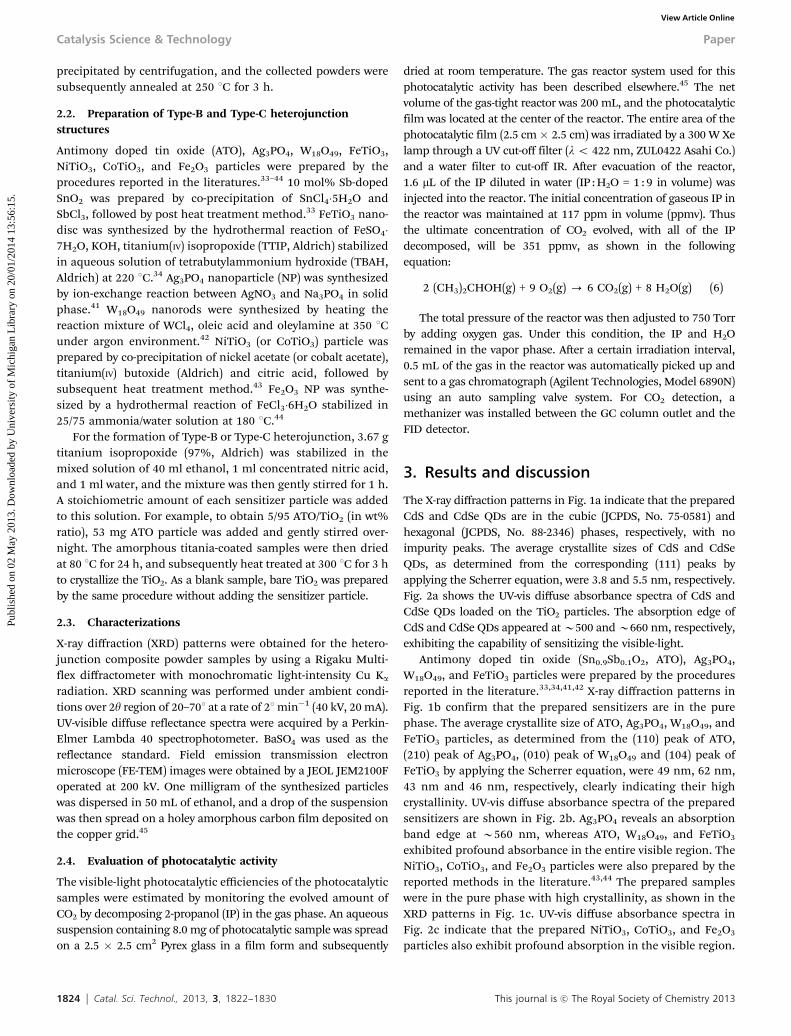
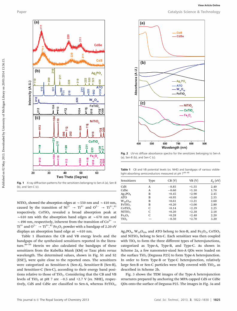
The X-ray diffraction patterns in Fig. 1a indicate that the preparedCdS and CdSe QDs are in the cubic (JCPDS, No. 75-0581) andhexagonal (JCPDS, No. 88-2346) phases, respectively, with noimpurity peaks. The average crystallite sizes of CdS and CdSeQDs, as determined from the corresponding (111) peaks byapplying the Scherrer equation, were 3.8 and 5.5 nm, respectively.Fig. 2a shows the UV-vis diffuse absorbance spectra of CdS andCdSe QDs loaded on the TiO2 particles. The absorption edge ofCdS and CdSe QDs appeared at B500 and B660 nm, respectively,exhibiting the capability of sensitizing the visible-light.
Antimony doped tin oxide (Sn0.9Sb0.1O2, ATO), Ag3PO4,W18O49, and FeTiO3 particles were prepared by the proceduresreported in the literature.33,34,41,42 X-ray diffraction patterns inFig. 1b confirm that the prepared sensitizers are in the purephase. The average crystallite size of ATO, Ag3PO4, W18O49, andFeTiO3 particles, as determined from the (110) peak of ATO,(210) peak of Ag3PO4, (010) peak of W18O49 and (104) peak ofFeTiO3 by applying the Scherrer equation, were 49 nm, 62 nm,43 nm and 46 nm, respectively, clearly indicating their highcrystallinity. UV-vis diffuse absorbance spectra of the preparedsensitizers are shown in Fig. 2b. Ag3PO4 reveals an absorptionband edge at B560 nm, whereas ATO, W18O49, and FeTiO3
exhibited profound absorbance in the entire visible region. TheNiTiO3, CoTiO3, and Fe2O3 particles were also prepared by thereported methods in the literature.43,44 The prepared sampleswere in the pure phase with high crystallinity, as shown in theXRD patterns in Fig. 1c. UV-vis diffuse absorbance spectra inFig. 2c indicate that the prepared NiTiO3, CoTiO3, and Fe2O3
particles also exhibit profound absorption in the visible region.
Catalysis Science & Technology Paper
Publ
ishe
d on
02
May
201
3. D
ownl
oade
d by
Uni
vers
ity o
f M
ichi
gan
Lib
rary
on
20/0
1/20
14 1
3:56
:15.
View Article Online
This journal is c The Royal Society of Chemistry 2013 Catal. Sci. Technol., 2013, 3, 1822--1830 1825
NiTiO3 showed the absorption edges at B550 nm and B410 nm,caused by the transition of Ni2+ - Ti4+ and O2� - Ti4+,43
respectively. CoTiO3 revealed a broad absorption peak atB610 nm with the absorption band edges at B670 nm andB490 nm, respectively, inherent from the transition of Co2+ -
Ti4+ and O2�- Ti4+.43 Fe2O3 powder with a bandgap of 2.20 eVdisplays an absorption band edge at B610 nm.
Table 1 illustrates the CB and VB energy levels and thebandgaps of the synthesized sensitizers reported in the litera-ture.46–50 Herein we also calculated the bandgaps of thesesensitizers from the Kubelka Munk (KM) or Tauc plots versuswavelength. The determined values, shown in Fig. S1 and S2(ESI†), were quite close to the reported ones. The sensitizerswere categorized as Sensitizer-A (Sen-A), Sensitizer-B (Sen-B),and Sensitizer-C (Sen-C), according to their energy band posi-tions relative to those of TiO2. Considering that the CB and VBlevels of TiO2 at pH 7 are �0.5 and +2.7 V (vs. NHE), respec-tively, CdS and CdSe are classified to Sen-A, whereas FeTiO3,
Ag3PO4, W18O49, and ATO belong to Sen-B, and Fe2O3, CoTiO3
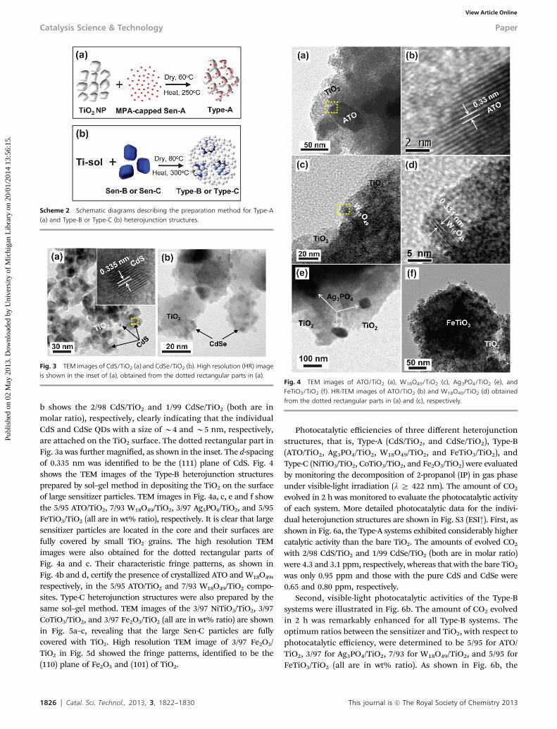
and NiTiO3 belong to Sen-C. Each sensitizer was then coupledwith TiO2 to form the three different types of heterojunctions,categorized as Type-A, Type-B, and Type-C. As shown inScheme 2a, a few nanometer-sized Sen-A QDs were loaded onthe surface TiO2 (Degussa P25) to form Type-A heterojunction.In order to form Type-B or Type-C heterojunction, relativelylarge Sen-B or Sen-C particles were fully covered with TiO2, asdescribed in Scheme 2b.
Fig. 3 shows the TEM images of the Type-A heterojunctionstructures prepared by anchoring the MPA capped CdS or CdSeQDs onto the surface of Degussa P25. The images in Fig. 3a and
Fig. 1 X-ray diffraction patterns for the sensitizers belonging to Sen-A (a), Sen-B(b), and Sen-C (c).
Fig. 2 UV-vis diffuse absorbance spectra for the sensitizers belonging to Sen-A(a), Sen-B (b), and Sen-C (c).
Table 1 CB and VB potential levels (vs. NHE) and bandgaps of various visible-light-absorbing semiconductors measured at pH 744–48
Sensitizers Type CB (V) VB (V) Eg (eV)
CdS A �0.85 +1.55 2.40CdSe A �0.60 +1.10 1.70Ag3PO4 B +0.45 +2.90 2.45ATO B +0.95 +3.60 2.55W18O49 B +0.61 +3.21 2.60FeTiO3 B +0.20 +3.00 2.80CoTiO3 C +0.14 +2.39 2.25NiTiO3 C +0.20 +2.38 2.18Fe2O3 C +0.28 +2.48 2.20TiO2 — �0.50 +2.70 3.20
Paper Catalysis Science & Technology
Publ
ishe
d on
02
May
201
3. D
ownl
oade
d by
Uni
vers
ity o
f M
ichi
gan
Lib
rary
on
20/0
1/20
14 1
3:56
:15.
View Article Online
1826 Catal. Sci. Technol., 2013, 3, 1822--1830 This journal is c The Royal Society of Chemistry 2013
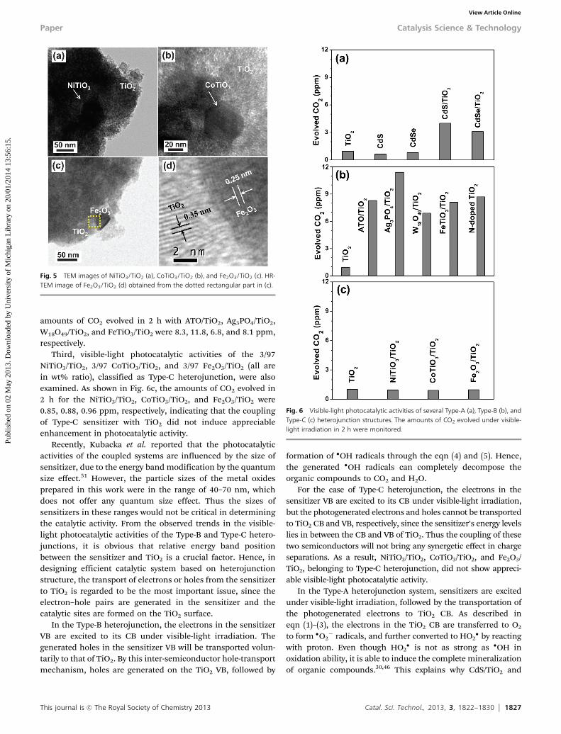
b shows the 2/98 CdS/TiO2 and 1/99 CdSe/TiO2 (both are inmolar ratio), respectively, clearly indicating that the individualCdS and CdSe QDs with a size of B4 and B5 nm, respectively,are attached on the TiO2 surface. The dotted rectangular part inFig. 3a was further magnified, as shown in the inset. The d-spacingof 0.335 nm was identified to be the (111) plane of CdS. Fig. 4shows the TEM images of the Type-B heterojunction structuresprepared by sol–gel method in depositing the TiO2 on the surfaceof large sensitizer particles. TEM images in Fig. 4a, c, e and f showthe 5/95 ATO/TiO2, 7/93 W18O49/TiO2, 3/97 Ag3PO4/TiO2, and 5/95FeTiO3/TiO2 (all are in wt% ratio), respectively. It is clear that largesensitizer particles are located in the core and their surfaces arefully covered by small TiO2 grains. The high resolution TEMimages were also obtained for the dotted rectangular parts ofFig. 4a and c. Their characteristic fringe patterns, as shown inFig. 4b and d, certify the presence of crystallized ATO and W18O49,respectively, in the 5/95 ATO/TiO2 and 7/93 W18O49/TiO2 compo-sites. Type-C heterojunction structures were also prepared by thesame sol–gel method. TEM images of the 3/97 NiTiO3/TiO2, 3/97CoTiO3/TiO2, and 3/97 Fe2O3/TiO2 (all are in wt% ratio) are shownin Fig. 5a–c, revealing that the large Sen-C particles are fullycovered with TiO2. High resolution TEM image of 3/97 Fe2O3/TiO2 in Fig. 5d showed the fringe patterns, identified to be the(110) plane of Fe2O3 and (101) of TiO2.
Photocatalytic efficiencies of three different heterojunctionstructures, that is, Type-A (CdS/TiO2, and CdSe/TiO2), Type-B(ATO/TiO2, Ag3PO4/TiO2, W18O49/TiO2, and FeTiO3/TiO2), andType-C (NiTiO3/TiO2, CoTiO3/TiO2, and Fe2O3/TiO2) were evaluatedby monitoring the decomposition of 2-propanol (IP) in gas phaseunder visible-light irradiation (l Z 422 nm). The amount of CO2
evolved in 2 h was monitored to evaluate the photocatalytic activityof each system. More detailed photocatalytic data for the indivi-dual heterojunction structures are shown in Fig. S3 (ESI†). First, asshown in Fig. 6a, the Type-A systems exhibited considerably highercatalytic activity than the bare TiO2. The amounts of evolved CO2
with 2/98 CdS/TiO2 and 1/99 CdSe/TiO2 (both are in molar ratio)were 4.3 and 3.1 ppm, respectively, whereas that with the bare TiO2
was only 0.95 ppm and those with the pure CdS and CdSe were0.65 and 0.80 ppm, respectively.
Second, visible-light photocatalytic activities of the Type-Bsystems were illustrated in Fig. 6b. The amount of CO2 evolvedin 2 h was remarkably enhanced for all Type-B systems. Theoptimum ratios between the sensitizer and TiO2, with respect tophotocatalytic efficiency, were determined to be 5/95 for ATO/TiO2, 3/97 for Ag3PO4/TiO2, 7/93 for W18O49/TiO2, and 5/95 forFeTiO3/TiO2 (all are in wt% ratio). As shown in Fig. 6b, the
Scheme 2 Schematic diagrams describing the preparation method for Type-A(a) and Type-B or Type-C (b) heterojunction structures.
Fig. 3 TEM images of CdS/TiO2 (a) and CdSe/TiO2 (b). High resolution (HR) imageis shown in the inset of (a), obtained from the dotted rectangular parts in (a).
Fig. 4 TEM images of ATO/TiO2 (a), W18O49/TiO2 (c), Ag3PO4/TiO2 (e), andFeTiO3/TiO2 (f). HR-TEM images of ATO/TiO2 (b) and W18O49/TiO2 (d) obtainedfrom the dotted rectangular parts in (a) and (c), respectively.
Catalysis Science & Technology Paper
Publ
ishe
d on
02
May
201
3. D
ownl
oade
d by
Uni
vers
ity o
f M
ichi
gan
Lib
rary
on
20/0
1/20
14 1
3:56
:15.
View Article Online
This journal is c The Royal Society of Chemistry 2013 Catal. Sci. Technol., 2013, 3, 1822--1830 1827
amounts of CO2 evolved in 2 h with ATO/TiO2, Ag3PO4/TiO2,W18O49/TiO2, and FeTiO3/TiO2 were 8.3, 11.8, 6.8, and 8.1 ppm,respectively.
Third, visible-light photocatalytic activities of the 3/97NiTiO3/TiO2, 3/97 CoTiO3/TiO2, and 3/97 Fe2O3/TiO2 (all arein wt% ratio), classified as Type-C heterojunction, were alsoexamined. As shown in Fig. 6c, the amounts of CO2 evolved in2 h for the NiTiO3/TiO2, CoTiO3/TiO2, and Fe2O3/TiO2 were0.85, 0.88, 0.96 ppm, respectively, indicating that the couplingof Type-C sensitizer with TiO2 did not induce appreciableenhancement in photocatalytic activity.
Recently, Kubacka et al. reported that the photocatalyticactivities of the coupled systems are influenced by the size ofsensitizer, due to the energy band modification by the quantumsize effect.51 However, the particle sizes of the metal oxidesprepared in this work were in the range of 40–70 nm, whichdoes not offer any quantum size effect. Thus the sizes ofsensitizers in these ranges would not be critical in determiningthe catalytic activity. From the observed trends in the visible-light photocatalytic activities of the Type-B and Type-C hetero-junctions, it is obvious that relative energy band positionbetween the sensitizer and TiO2 is a crucial factor. Hence, indesigning efficient catalytic system based on heterojunctionstructure, the transport of electrons or holes from the sensitizerto TiO2 is regarded to be the most important issue, since theelectron–hole pairs are generated in the sensitizer and thecatalytic sites are formed on the TiO2 surface.
In the Type-B heterojunction, the electrons in the sensitizerVB are excited to its CB under visible-light irradiation. Thegenerated holes in the sensitizer VB will be transported volun-tarily to that of TiO2. By this inter-semiconductor hole-transportmechanism, holes are generated on the TiO2 VB, followed by
formation of �OH radicals through the eqn (4) and (5). Hence,the generated �OH radicals can completely decompose theorganic compounds to CO2 and H2O.
For the case of Type-C heterojunction, the electrons in thesensitizer VB are excited to its CB under visible-light irradiation,but the photogenerated electrons and holes cannot be transportedto TiO2 CB and VB, respectively, since the sensitizer’s energy levelslies in between the CB and VB of TiO2. Thus the coupling of thesetwo semiconductors will not bring any synergetic effect in chargeseparations. As a result, NiTiO3/TiO2, CoTiO3/TiO2, and Fe2O3/TiO2, belonging to Type-C heterojunction, did not show appreci-able visible-light photocatalytic activity.
In the Type-A heterojunction system, sensitizers are excitedunder visible-light irradiation, followed by the transportation ofthe photogenerated electrons to TiO2 CB. As described ineqn (1)–(3), the electrons in the TiO2 CB are transferred to O2
to form �O2� radicals, and further converted to HO2
� by reactingwith proton. Even though HO2
� is not as strong as �OH inoxidation ability, it is able to induce the complete mineralizationof organic compounds.30,46 This explains why CdS/TiO2 and
Fig. 5 TEM images of NiTiO3/TiO2 (a), CoTiO3/TiO2 (b), and Fe2O3/TiO2 (c). HR-TEM image of Fe2O3/TiO2 (d) obtained from the dotted rectangular part in (c).
Fig. 6 Visible-light photocatalytic activities of several Type-A (a), Type-B (b), andType-C (c) heterojunction structures. The amounts of CO2 evolved under visible-light irradiation in 2 h were monitored.
Paper Catalysis Science & Technology
Publ
ishe
d on
02
May
201
3. D
ownl
oade
d by
Uni
vers
ity o
f M
ichi
gan
Lib
rary
on
20/0
1/20
14 1
3:56
:15.
View Article Online
1828 Catal. Sci. Technol., 2013, 3, 1822--1830 This journal is c The Royal Society of Chemistry 2013
CdSe/TiO2 systems showed considerably enhanced visible-lightphotocatalytic activities, compared with the bare TiO2.
Herein it was found that Type-B heterojunction systems exhib-ited relatively higher catalytic activity than the Type-A systems.Moreover, some of the Type-B systems showed comparable oreven higher activity than the typical N-doped TiO2. Basically,direct comparison of activity among the different photocatalyticsystems is not simple, since the several factors such as particlesize of sensitizer, contact and charge transport between sensitizerand TiO2, and others, are involved in determining the photo-catalytic activity. Nonetheless, Type-B systems seem to have asignificant advantage in photocatalytic oxidation reactions due tothe availability of �OH radicals in the TiO2 VB. The produced �OHradicals, known as the most powerful oxidant, can induce fast andcomplete decomposition of organic pollutants, rationalizing theenhanced photocatalytic efficiency of Type-B systems.
In order to confirm the hole-transfer mechanism betweenthe VB of sensitizer and TiO2 in the Type-B heterojunction, theevidence for the generation of holes in TiO2 VB was investigatedby monitoring the chemical reaction of the iodide ion (I�),known as a hole scavenger. As a Type-B heterojunction system,ATO/TiO2 was used in this experiment. Generally, I�/I3
� redoxcouple has been used as electrolyte mediating the charges inthe dye-sensitized solar cells, and the role of I� ions is acceptingthe holes from the HOMO of dye.52,53 Therefore, it is deducedthat the I� ions can be oxidized to triiodide (I3
�) by reacting withthe generated holes in the ATO or TiO2, as shown in eqn (7),since the redox potential of I�/I3
� is +0.536 V,54 which lies muchhigher than the VB position of ATO (+3.6 V)33 or TiO2 (+2.7 V).46
2h+(VB) + 3I�(aq) - I3�(aq) (7)
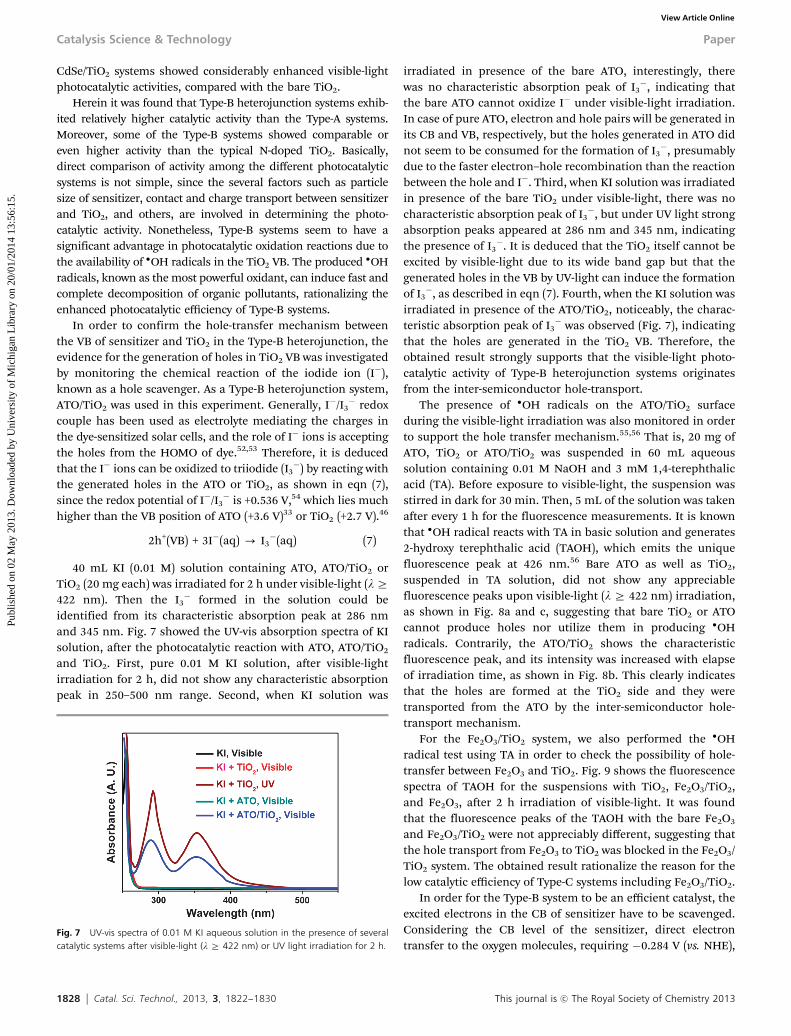
40 mL KI (0.01 M) solution containing ATO, ATO/TiO2 orTiO2 (20 mg each) was irradiated for 2 h under visible-light (lZ422 nm). Then the I3
� formed in the solution could beidentified from its characteristic absorption peak at 286 nmand 345 nm. Fig. 7 showed the UV-vis absorption spectra of KIsolution, after the photocatalytic reaction with ATO, ATO/TiO2
and TiO2. First, pure 0.01 M KI solution, after visible-lightirradiation for 2 h, did not show any characteristic absorptionpeak in 250–500 nm range. Second, when KI solution was
irradiated in presence of the bare ATO, interestingly, therewas no characteristic absorption peak of I3
�, indicating thatthe bare ATO cannot oxidize I� under visible-light irradiation.In case of pure ATO, electron and hole pairs will be generated inits CB and VB, respectively, but the holes generated in ATO didnot seem to be consumed for the formation of I3
�, presumablydue to the faster electron–hole recombination than the reactionbetween the hole and I�. Third, when KI solution was irradiatedin presence of the bare TiO2 under visible-light, there was nocharacteristic absorption peak of I3
�, but under UV light strongabsorption peaks appeared at 286 nm and 345 nm, indicatingthe presence of I3
�. It is deduced that the TiO2 itself cannot beexcited by visible-light due to its wide band gap but that thegenerated holes in the VB by UV-light can induce the formationof I3
�, as described in eqn (7). Fourth, when the KI solution wasirradiated in presence of the ATO/TiO2, noticeably, the charac-teristic absorption peak of I3
� was observed (Fig. 7), indicatingthat the holes are generated in the TiO2 VB. Therefore, theobtained result strongly supports that the visible-light photo-catalytic activity of Type-B heterojunction systems originatesfrom the inter-semiconductor hole-transport.
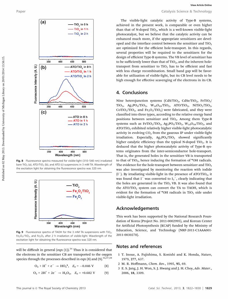
The presence of �OH radicals on the ATO/TiO2 surfaceduring the visible-light irradiation was also monitored in orderto support the hole transfer mechanism.55,56 That is, 20 mg ofATO, TiO2 or ATO/TiO2 was suspended in 60 mL aqueoussolution containing 0.01 M NaOH and 3 mM 1,4-terephthalicacid (TA). Before exposure to visible-light, the suspension wasstirred in dark for 30 min. Then, 5 mL of the solution was takenafter every 1 h for the fluorescence measurements. It is knownthat �OH radical reacts with TA in basic solution and generates2-hydroxy terephthalic acid (TAOH), which emits the uniquefluorescence peak at 426 nm.56 Bare ATO as well as TiO2,suspended in TA solution, did not show any appreciablefluorescence peaks upon visible-light (l Z 422 nm) irradiation,as shown in Fig. 8a and c, suggesting that bare TiO2 or ATOcannot produce holes nor utilize them in producing �OHradicals. Contrarily, the ATO/TiO2 shows the characteristicfluorescence peak, and its intensity was increased with elapseof irradiation time, as shown in Fig. 8b. This clearly indicatesthat the holes are formed at the TiO2 side and they weretransported from the ATO by the inter-semiconductor hole-transport mechanism.
For the Fe2O3/TiO2 system, we also performed the �OHradical test using TA in order to check the possibility of hole-transfer between Fe2O3 and TiO2. Fig. 9 shows the fluorescencespectra of TAOH for the suspensions with TiO2, Fe2O3/TiO2,and Fe2O3, after 2 h irradiation of visible-light. It was foundthat the fluorescence peaks of the TAOH with the bare Fe2O3
and Fe2O3/TiO2 were not appreciably different, suggesting thatthe hole transport from Fe2O3 to TiO2 was blocked in the Fe2O3/TiO2 system. The obtained result rationalize the reason for thelow catalytic efficiency of Type-C systems including Fe2O3/TiO2.
In order for the Type-B system to be an efficient catalyst, theexcited electrons in the CB of sensitizer have to be scavenged.Considering the CB level of the sensitizer, direct electrontransfer to the oxygen molecules, requiring �0.284 V (vs. NHE),
Fig. 7 UV-vis spectra of 0.01 M KI aqueous solution in the presence of severalcatalytic systems after visible-light (l Z 422 nm) or UV light irradiation for 2 h.
Catalysis Science & Technology Paper
Publ
ishe
d on
02
May
201
3. D
ownl
oade
d by
Uni
vers
ity o
f M
ichi
gan
Lib
rary
on
20/0
1/20
14 1
3:56
:15.
View Article Online
This journal is c The Royal Society of Chemistry 2013 Catal. Sci. Technol., 2013, 3, 1822--1830 1829
will be difficult in general (eqn (1)).34 Thus it is considered thatthe electrons in the sensitizer CB are transported to the oxygenspecies through the processes described in eqn (8) and (9).54,57,58
O2 + H+ + e� - HO2�, E0 = �0.046 V (8)
O2 + 2H+ + 2e� - H2O2, E0 = +0.682 V (9)
The visible-light catalytic activity of Type-B systems,achieved in the present work, is comparable or even higherthan that of N-doped TiO2, which is a well-known visible-lightphotocatalyst, but we believe that the catalytic activity can beenhanced much more, if the appropriate sensitizers are devel-oped and the interface control between the sensitizer and TiO2
are optimized for the efficient hole-transport. In this regards,several properties will be required to the sensitizers for thedesign of efficient Type-B systems. The VB level of sensitizer hasto be sufficiently lower than that of TiO2, and the inherent hole-transport from sensitizer to TiO2 has to be efficient and fastwith less charge recombination. Small band gap will be favor-able for utilization of visible-light, but its CB level needs to behigh enough for effective scavenging of the electrons in its CB.
4. Conclusions
Nine heterojunction systems (CdS/TiO2, CdSe/TiO2, FeTiO3/TiO2, Ag3PO4/TiO2, W18O49/TiO2, ATO/TiO2, NiTiO3/TiO2,CoTiO3/TiO2, and Fe2O3/TiO2) were fabricated, and they wereclassified into three types, according to the relative energy bandpositions between sensitizer and TiO2. Among them Type-Bsystems such as FeTiO3/TiO2, Ag3PO4/TiO2, W18O49/TiO2, andATO/TiO2 exhibited relatively higher visible-light photocatalyticactivity in evolving CO2 from the gaseous IP under visible-lightirradiation. Especially, Ag3PO4/TiO2 showed significantlyhigher catalytic efficiency than the typical N-doped TiO2. It isdeduced that the higher photocatalytic activity of Type-B sys-tems originates from the inter-semiconductor hole-transport.That is, the generated holes in the sensitizer VB is transportedto that of TiO2, hence inducing the formation of �OH radicals.The evidence for the hole-transport between sensitizer and TiO2
was also investigated by monitoring the reaction with iodide(I�). By irradiating visible-light in the presence of ATO/TiO2, itwas found that I� was converted to I3
�, clearly indicating thatthe holes are generated in the TiO2 VB. It was also found thatthe ATO/TiO2 system can convert the TA to TAOH, which isevident for the formation of �OH radicals in TiO2 side undervisible-light irradiation.
Acknowledgements
This work has been supported by the National Research Foun-dation of Korea (Project No. 2011-0002995), and Korean Centerfor Artificial Photosynthesis (KCAP) funded by the Ministry ofEducation, Science, and Technology (NRF-2011-C1AAA001-2011-0030278).
Notes and references
1 T. Inoue, A. Fujishima, S. Konishi and K. Honda, Nature,1979, 277, 637.
2 M. R. Hoffmann, Chem. Rev., 1995, 95, 69.3 E. S. Jang, J. H. Won, S. J. Hwang and J. H. Choy, Adv. Mater.,
2006, 18, 3309.
Fig. 8 Fluorescence spectra measured for visible-light (310–540 nm) irradiatedbare TiO2 (a), ATO/TiO2 (b), and ATO (c) suspensions in 3 mM TA. Wavelength ofthe excitation light for obtaining the fluorescence spectra was 320 nm.
Fig. 9 Fluorescence spectra of TAOH for the 3 mM TA suspensions with TiO2,Fe2O3/TiO2, and Fe2O3 after 2 h irradiation of visible-light. Wavelength of theexcitation light for obtaining the fluorescence spectra was 320 nm.
Paper Catalysis Science & Technology
Publ
ishe
d on
02
May
201
3. D
ownl
oade
d by
Uni
vers
ity o
f M
ichi
gan
Lib
rary
on
20/0
1/20
14 1
3:56
:15.
View Article Online

1830 Catal. Sci. Technol., 2013, 3, 1822--1830 This journal is c The Royal Society of Chemistry 2013
4 Z. Ding, G. Q. Lu and P. F. Greenfield, J. Phys. Chem. B, 2000,104, 4815.
5 Y. Ou, J. Lin, S. Fang and D. Liao, Catal. Commun., 2007,8, 936.
6 Y. Huang, Z. Zheng, Z. Ai, L. Zhang, X. Fan and Z. Zou,J. Phys. Chem. B, 2006, 110, 19323.
7 C. Burda, Y. Lou, X. Chen, A. C. S. Samia, J. Stout andJ. L. Gole, Nano Lett., 2003, 3, 1049.
8 V. Stengl, V. Houskova, S. Bakardjieva and N. Murafa, ACSAppl. Mater. Interfaces, 2010, 2, 575.
9 S. Sakthivel and H. Kisch, ChemPhysChem, 2003, 4, 487.10 K. Y. Song, M. K. Park, Y. T. Kwon, H. W. Lee, W. J. Chung
and W. I. Lee, Chem. Mater., 2001, 13, 2349.11 L.-L. Tan, S.-P. Chai and A. R. Mohamed, ChemSusChem,
2012, 5, 1868.12 M. Anpo and M. Takeuchi, J. Catal., 2003, 216, 505.13 B. K. Vijayan, N. M. Dimitrijevic, J. Wu and K. A. Gray,
J. Phys. Chem. C, 2010, 114, 21262.14 P. Bouras, E. Stathatos and P. Lianos, Appl. Catal., B, 2007,
73, 51.15 R. Asahi, T. Morikawa, T. Ohwaki, K. Aoki and Y. Taga,
Science, 2001, 293, 269.16 S. U. M. Khan, M. Al-Shahry and W. B. Ingler, Science, 2002,
297, 2243.17 W. Zhao, W. Ma, C. Chen, J. Zhao and Z. Shuai, J. Am. Chem.
Soc., 2004, 126, 4782.18 J. C. Yu, W. Ho, J. Yu, H. Yip, P. K. Wong and J. Zhao,
Environ. Sci. Technol., 2005, 39, 1175.19 W. J. Ong, M. M. Gui, S. P. Chai and A. R. Mohamed, RSC
Adv., 2013, 3, 4505.20 Y. Zhang, N. Zhang, Z. R. Tang and Y. J. Xu, Phys. Chem.
Chem. Phys., 2012, 14, 9167.21 D. Liu and P. V. Kamat, J. Electroanal. Chem., 1993, 347, 451.22 L. Spanhel, H. Weller and A. Henglein, J. Am. Chem. Soc.,
1987, 109, 6632.23 S. Y. Chai, Y. J. Kim, M. H. Jung, A. K. Chakraborty, D. Jung
and W. I. Lee, J. Catal., 2009, 262, 144.24 S. B. Rawal, S. D. Sung and W. I. Lee, Catal. Commun., 2012,
17, 131.25 S. N. Frank and A. J. Bard, J. Phys. Chem., 1977, 81, 1484.26 W. Ho and J. C. Yu, J. Mol. Catal. A: Chem., 2006, 247, 268.27 E. Bae, W. Choi, J. Park, H. S. Shin, S. B. Kim and J. S. Lee,
J. Phys. Chem. B, 2004, 108, 14093.28 X. Yu, Q. Wu, S. Jiang and Y. Guo, Mater. Charact., 2006,
57, 333.29 J. C. Kim, J. K. Choi, Y. B. Lee, J. H. Hong, J. I. Lee,
J. W. Yang, W. I. Lee and N. H. Hur, Chem. Commun.,2006, 5024.
30 Y. Bessekhouad, N. Chaoui, M. Trzpit, N. Ghazzal, D. Robertand J. V. Weber, J. Photochem. Photobiol., A, 2006, 183, 218.
31 A. G. Agrios and P. Pichat, J. Appl. Electrochem., 2005, 35, 655.32 U. I. Gaya and A. H. Abdullah, J. Photochem. Photobiol., C,
2008, 9, 1.
33 S. B. Rawal, A. K. Chakraborty, Y. J. Kim, H. J. Kim andW. I. Lee, RSC Adv., 2012, 2, 622.
34 Y. J. Kim, B. Gao, S. Y. Han, M. H. Jung, A. K. Chakraborty,T. Ko, C. Lee and W. I. Lee, J. Phys. Chem. C, 2009,113, 19179.
35 S. Shamaila, A. K. L. Sajjad, F. Chen and J. Zhang, J. ColloidInterface Sci., 2011, 356, 465.
36 H. Gnaser, M. R. Savina, W. F. Chalaway, C. E. Tripa,I. V. Veryovkin and M. J. Pellin, Int. J. Mass Spectrom.,2005, 245, 61.
37 B. Gao, Y. J. Kim, A. K. Chakraborty and W. I. Lee, Appl.Catal., B, 2008, 83, 202.
38 W. W. Yu and X. Peng, Angew. Chem., Int. Ed., 2002, 41, 2368.39 Q. Dai, D. Li, H. Chen, S. Kan, H. Li, S. Gao, Y. Hou, B. Liu
and G. Zou, J. Phys. Chem. B, 2006, 110, 16509.40 K. S. Leschkies, R. Divakar, J. Basu, E. E. Pommer,
J. E. Boercker, C. B. Carter, U. R. Kortshagen, D. J. Norrisand E. S. Aydil, Nano Lett., 2007, 7, 1793.
41 Z. Yi, J. Ye, N. Kikugawa, T. Kako, S. Ouyang, H. S. Williams,H. Yang, J. Cao, W. Luo, Z. Li, Y. Liu and R. L. Withers, Nat.Mater., 2010, 9, 559.
42 J. W. Seo, Y. W. Jun, S. J. Ko and J. W. Cheon, J. Phys. Chem.B, 2005, 109, 5389.
43 Y. J. Lin, Y. H. Chang, W. D. Yang and B. S. Tsai, J. Non-Cryst. Solids, 2006, 352, 789.
44 J. Ma, J. Lian, X. Duan, X. Liu and W. Zheng, J. Phys. Chem.C, 2010, 114, 10671.
45 Y. T. Kwon, K. Y. Song, W. I. Lee, G. J. Choi and Y. R. Do,J. Catal., 2000, 191, 192.
46 N. Serpone, P. Maruthamuthu, P. Pichat, E. Pelizzetti andH. Hidaka, J. Photochem.Photobiol., A, 1995, 85, 247.
47 P. V. Kamat, Chem. Rev., 1993, 93, 267.48 Y. Xu and A. A. Schoonen, Am. Mineral., 2000, 85, 543.49 S. B. Rawal, S. Bera and W. I. Lee, Catal. Lett., 2012,
142, 1482.50 Z. Q. Li, Y. L. Yin, X. D. Liu, L. Y. Li, H. Liu and Q. G. Song,
J. Appl. Phys., 2009, 106, 083701.51 A. Kubacka, M. Fernandez-Garcıa and G. Colon, Chem. Rev.,
2012, 112, 1555.52 M. Gratzel, Nature, 2001, 414, 338.53 M. Wang, N. Chamberland, L. Breau, J. E. Moser,
R. H. Baker, B. Marsan, S. M. Zakeeruddin and M. Gratzel,Nat. Chem., 2010, 2, 385.
54 Handbook of Chemistry and Physics, ed. C. R. Weast, CRCPress, Boca Raton, FL, 77th edn 1996.
55 T. Hirakawa and Y. Nosaka, Langmuir, 2002, 18, 3247.56 G. Liu, C. Sun, L. Cheng, Y. Jin, H. Lu, L. Wang, S. C. Smith,
G. Q. Lu and H. M. Cheng, J. Phys. Chem. C, 2009,113, 12317.
57 A. B. Anderson and T. V. Albu, J. Am. Chem. Soc., 1999,121, 11855.
58 H. Irie, S. Miura, K. Kamiya and K. Hashimoto, Chem. Phys.Lett., 2008, 457, 202.
Catalysis Science & Technology Paper
Publ
ishe
d on
02
May
201
3. D
ownl
oade
d by
Uni
vers
ity o
f M
ichi
gan
Lib
rary
on
20/0
1/20
14 1
3:56
:15.
View Article Online