
Design of Sub-THz Beam Scanning Antenna Using Luneburg ...
13
Progress In Electromagnetics Research C, Vol. 99, 179–191, 2020 Design of Sub-THz Beam Scanning Antenna Using Luneburg Lens for 5G Communications or Beyond Thevaruparambil A. Nisamol * , Kunnath K. Ansha, and Parambil Abdulla Abstract—This work presents the design and simulation of a beam scanning antenna at 300 GHz using Luneburg lens for 5th generation communication applications or beyond. The basic antenna consists of a highly directional Yagi-Uda antenna with lens shaped configuration (substrate lens antenna-SLA) and designed using multiple parallel elements such as one reflector and one driven element with 6 directors. The SLA is focused by Luneburg lens, which is modeled using a unique foam material AirexR82 with relative dielectric constant of 1.12, and it is pressed to realize different dielectric constants in order to obey the index law inside the lens. The final nine-element array of SLA integrated with Luneburg lens provides a 50% increase in bandwidth compared with conventional Yagi-Uda antenna along with an increase in the gain of 31.3% compared with single SLA. The designed model can achieve a beam scan coverage up to 146 ◦ with a maximum gain of 17.1 dBi and an estimated efficiency of 92.9%. The beam scanning antenna provides a wide bandwidth of 83 GHz starting from 289 GHz to 372 GHz. The analysis of the proposed antenna is done in CST suite and is validated using HFSS software. 1. INTRODUCTION The evolution of the ultra-fast mobile communication systems during the last few decades increases the demand of THz and sub-THz millimeter wave antennas. The design and development of antenna units are transformed beyond the fifth-generation wireless communication bands [1]. For the transmission of signals, researchers are searching for THz and sub-THz frequency bands (0.1 THz–10 THz), since very high data rates within the confined duration are becoming the major goal in the emerging communication field. In the past 20 years, NASA has been leading Terahertz (THz) technology development for the sensors and instruments in astronomy. THz technologies are expanding into much broader applications in recent years. Moreover, the emerging THz antennas extend their imaging technique towards the screening of metals, weapons, explosives in the military application [2]. Full duplex system which suppresses self interference is required for wide-band communication networks. Dual polarized antennas can be used with the full-isolation and SI reduction at 300 GHz [3]. However, the properties of higher losses at THz frequency than the losses observed at antennas working in lower frequency band below 0.1 THz limit the complete reduction of SI and isolation. The design and criteria to enhance the gain and bandwidth of the antennas at higher frequencies are detailed in [4]. For the bandwidth extension and reduction in the reflection losses, the novel technologies in the field of reflect array antennas at 300 GHz were developed in [5, 6]. Since it is hard to limit the reflections around the high frequency resonances, there will be poor reflection loss characteristics at 300 GHz. While dealing with the recent developments in this band, the measurement setup with maximum accuracy of reflection losses is required. Some of the measurement techniques at sub-THz frequency bands were discussed in [7, 8]. The works advancing in THz frequency [9, 10] range also have high significance for the future communication applications. Received 11 December 2019, Accepted 22 January 2020, Scheduled 7 February 2020 * Corresponding author: Thevaruparambil Abdulnazer Nisamol ([email protected]). The authors are with Division of Electronics, Cochin University of Science and Technology, India.
-
Upload
khangminh22 -
Category
Documents
-
view
10 -
download
0
Transcript of Design of Sub-THz Beam Scanning Antenna Using Luneburg ...
Progress In Electromagnetics Research C, Vol. 99, 179–191, 2020
Design of Sub-THz Beam Scanning Antenna Using Luneburg Lensfor 5G Communications or Beyond
Thevaruparambil A. Nisamol*, Kunnath K. Ansha, and Parambil Abdulla
Abstract—This work presents the design and simulation of a beam scanning antenna at 300 GHz usingLuneburg lens for 5th generation communication applications or beyond. The basic antenna consists ofa highly directional Yagi-Uda antenna with lens shaped configuration (substrate lens antenna-SLA) anddesigned using multiple parallel elements such as one reflector and one driven element with 6 directors.The SLA is focused by Luneburg lens, which is modeled using a unique foam material AirexR82 withrelative dielectric constant of 1.12, and it is pressed to realize different dielectric constants in orderto obey the index law inside the lens. The final nine-element array of SLA integrated with Luneburglens provides a 50% increase in bandwidth compared with conventional Yagi-Uda antenna along withan increase in the gain of 31.3% compared with single SLA. The designed model can achieve a beamscan coverage up to 146◦ with a maximum gain of 17.1 dBi and an estimated efficiency of 92.9%. Thebeam scanning antenna provides a wide bandwidth of 83 GHz starting from 289 GHz to 372 GHz. Theanalysis of the proposed antenna is done in CST suite and is validated using HFSS software.
1. INTRODUCTION
The evolution of the ultra-fast mobile communication systems during the last few decades increases thedemand of THz and sub-THz millimeter wave antennas. The design and development of antenna unitsare transformed beyond the fifth-generation wireless communication bands [1]. For the transmission ofsignals, researchers are searching for THz and sub-THz frequency bands (0.1 THz–10 THz), since veryhigh data rates within the confined duration are becoming the major goal in the emerging communicationfield. In the past 20 years, NASA has been leading Terahertz (THz) technology development for thesensors and instruments in astronomy. THz technologies are expanding into much broader applicationsin recent years. Moreover, the emerging THz antennas extend their imaging technique towards thescreening of metals, weapons, explosives in the military application [2]. Full duplex system whichsuppresses self interference is required for wide-band communication networks. Dual polarized antennascan be used with the full-isolation and SI reduction at 300 GHz [3]. However, the properties of higherlosses at THz frequency than the losses observed at antennas working in lower frequency band below0.1 THz limit the complete reduction of SI and isolation.
The design and criteria to enhance the gain and bandwidth of the antennas at higher frequencies aredetailed in [4]. For the bandwidth extension and reduction in the reflection losses, the novel technologiesin the field of reflect array antennas at 300 GHz were developed in [5, 6]. Since it is hard to limitthe reflections around the high frequency resonances, there will be poor reflection loss characteristicsat 300 GHz. While dealing with the recent developments in this band, the measurement setup withmaximum accuracy of reflection losses is required. Some of the measurement techniques at sub-THzfrequency bands were discussed in [7, 8]. The works advancing in THz frequency [9, 10] range also havehigh significance for the future communication applications.
Received 11 December 2019, Accepted 22 January 2020, Scheduled 7 February 2020* Corresponding author: Thevaruparambil Abdulnazer Nisamol ([email protected]).The authors are with Division of Electronics, Cochin University of Science and Technology, India.
180 Nisamol, Ansha, and Abdulla
The high gain antennas acquire more significance in high frequency applications. Highly directionalprinted Yagi-Uda antenna is the most common directive antenna which can achieve high gain anddirectivity using linear dipole elements such as reflector, directors, and feeding element. These kindsof antennas serve high data rates applications such as WIFI, WIMAX, and WLAN technologies. Theyare widely used to obtain broad bandwidth for communication applications, and most of the works arecarried out on low frequency bands in the past years whose various wireless areas are already occupiedwith low data rates.
A planar Yagi-Uda antenna was used to provide high directivity to reduce free space path loss [11]and achieve better impedance matching when it was integrated with other circuits [12]. At lowerfrequencies, the bandwidth can be enhanced by varying the length and width of directors of the Yagi-Uda antenna which makes it suitable for RFID communication systems [13, 14]. A highly directionalYagi antenna at 193.5 THz was developed in [15] using modern techniques, particularly nano-photonicscircuits and photovoltaic devices. The antenna developed in nano wavelengths is termed as nantennawhich provides directivity of 16.6 dBi. Also, Yagi-Uda antenna gain possesses higher significance, andby focusing the power transmitted into the desired areas, the directivity can be further improved withlower interference levels [15]. It is evidently observed that the gain and directivity can be optimized bythe number of directors [16, 17]. Also, the length and spacing between the reflector and directors in theYagi-Uda setup plays a dominant role in the antenna performance [18].
These kinds of antennas are well suitable for source antenna design in beam scanning applications.Realization of wide-angle beam coverage is considered as a huge achievement in the field of modernwireless communication systems. This can be accomplished using integrated lens technique such asLuneburg lens which provides wide angle beam scanning property that is offered by the existence offocal points along the circumference. In [19], the authors introduce a six-layer Luneburg lens integratedwith Substrate integrated waveguide (SIW) antenna at 79 GHz for the wide beam scanning in automotiveradar application. It provides a maximum gain of 15 dBi and covers 170◦ beam scan. Several structuresof Luneburg lens with array configuration have been reported [20–26] for various applications. Thebeam steering at 60 GHz using Luneburg lens is depicted in [21] and achieves high gain of 18 dBi.Anyhow, the beam covers only up to 60◦ of scan angle, and only 9 GHz bandwidth is accomplished.The 2D Luneburg lens presented in [24] varies the refractive index according to change in width aftercombining meander crossed microstrip line. Luneburg lens can also be designed using PCB process andimplemented in W band which involves simple fabrication process [25]. Realization of beam scanningarray with Luneburg lens is performed by utilizing the switching units which automatically switches thearray element into a predefined beam angle. The printed Yagi-Uda array antenna designed at 300 GHz[27] is investigated and observed, and it can be used as a source antenna for the wide-angle beamscanning. It can be improved by the substrate lens antenna which provides narrow beam directivity.An integrated lens antenna with wide focal points at the circumference after compression provides wideangle beam coverage [28]. This provides only up to 86◦ scan angle with a bandwidth of 76–81 GHz.
In this work, Luneburg lens is integrated with an array of highly efficient Yagi-Uda substratelens antenna (SLA) in a semicircular way to obtain a wide-angle beam scanning of 146 degrees around300 GHz. The maximum realized gain of 17.1 dBi with 83 GHz bandwidth is achieved using the proposeddesign.
Section 2 shows the primary design of a sub-THz Yagi-Uda antenna with the analysis of gainand bandwidth for different numbers of directors. The Luneburg lens with six layers having differentpermittivities is designed in Section 3. Section 4 provides beam scanning by placing the SLA towardsthe circumference of the Luneburg lens. The array of SLA with Luneburg lens provides a high gainof 17.1 dBi and a bandwidth of 82 GHz with a beam coverage of 146◦. The results are verified andvalidated using CST and HFSS simulation software.
2. YAGI-UDA ANTENNA DESIGN
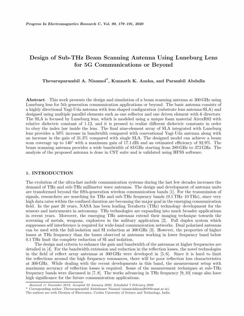
In this section, the design of a Yagi-Uda antenna to maximize the radiation in one direction is presented.Figures 1(a)–(b) illustrate the perspective and front view geometry of the proposed optimized Yagi-Udaantenna, and the analysis of antenna using gain and bandwidth is detailed in this section. The designrequirements of the antenna are given in Table 1.
Progress In Electromagnetics Research C, Vol. 99, 2020 181
(a)
S
W R Port
L
InP BCB
Ld
Reflector Active dipole
D1 D2 D3 D4 D5 D6
Directors
Port
Sd
(b)
Figure 1. Designed geometry of Yagi-Uda antenna. (a) Perspective view. (b) Top view.
Table 1. Design requirements of Yagi-Uda antenna.
Elements Length of the elementsLength of the feeding element (Ld) 0.45λ–0.49λ
Length of the reflector (R)Slightly greater thanthe feeding element
Spacing between the reflector andthe feeding element (S)
Around 0.25λ
Length of directors (D) 0.4λ–0.45λSpacing between the directors (SD) 0.3λ–0.4λ
The active dipole element is placed next to the reflector at a distance of λ/4 in order to enhancedirectivity and gain in the desired direction where λ is the wavelength corresponding to the designedfrequency (300 GHz). The substrate used for the Yagi-Uda design is composed of two layers, and thedetails of the layers are given in Table 2.
Table 2. The material details used in the design.
Substrate Permittivity Height Loss TangentIndium Phosphide (InP) 12.5 6 µm 0.002Benzocyclobutene (BCB) 2.5 50 µm 0.005
The Yagi-Uda antenna design is printed on a 2 layered substrate in which the bottom layer materialBenzocyclobutene (BCB) having dielectric constant of 2.5 with loss tangent of 0.0005 which shows stablebehavior over broadband THz frequencies [22]. Both materials having different dielectric constant showvery high geometric tolerance up to 350 GHz. The accuracy of the proposed design with the doublelayered substrate will be high and stable for the frequencies up to 380 GHz.
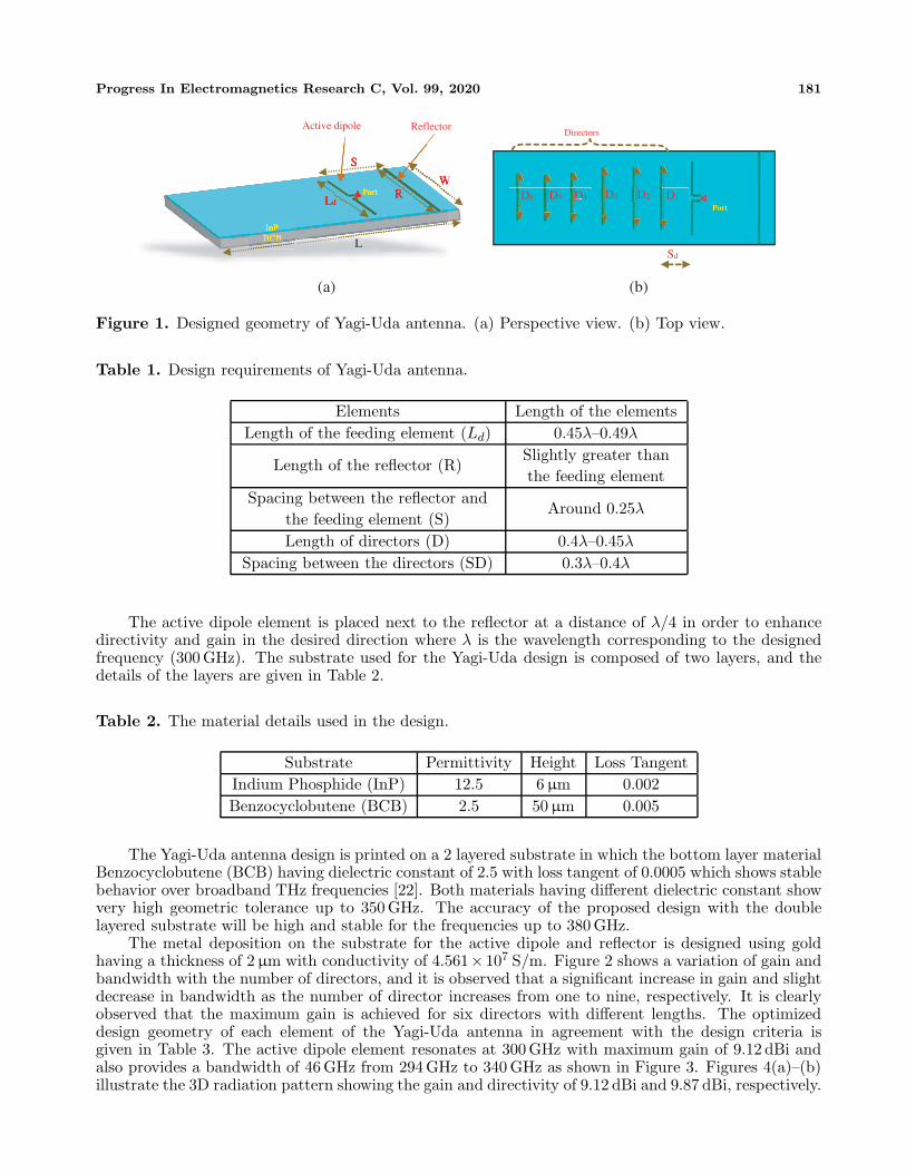
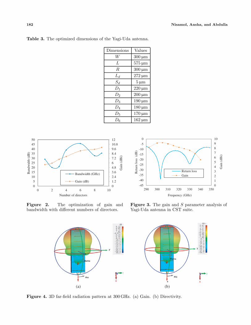
The metal deposition on the substrate for the active dipole and reflector is designed using goldhaving a thickness of 2 µm with conductivity of 4.561×10⁷ S/m. Figure 2 shows a variation of gain andbandwidth with the number of directors, and it is observed that a significant increase in gain and slightdecrease in bandwidth as the number of director increases from one to nine, respectively. It is clearlyobserved that the maximum gain is achieved for six directors with different lengths. The optimizeddesign geometry of each element of the Yagi-Uda antenna in agreement with the design criteria isgiven in Table 3. The active dipole element resonates at 300 GHz with maximum gain of 9.12 dBi andalso provides a bandwidth of 46 GHz from 294 GHz to 340 GHz as shown in Figure 3. Figures 4(a)–(b)illustrate the 3D radiation pattern showing the gain and directivity of 9.12 dBi and 9.87 dBi, respectively.
182 Nisamol, Ansha, and Abdulla
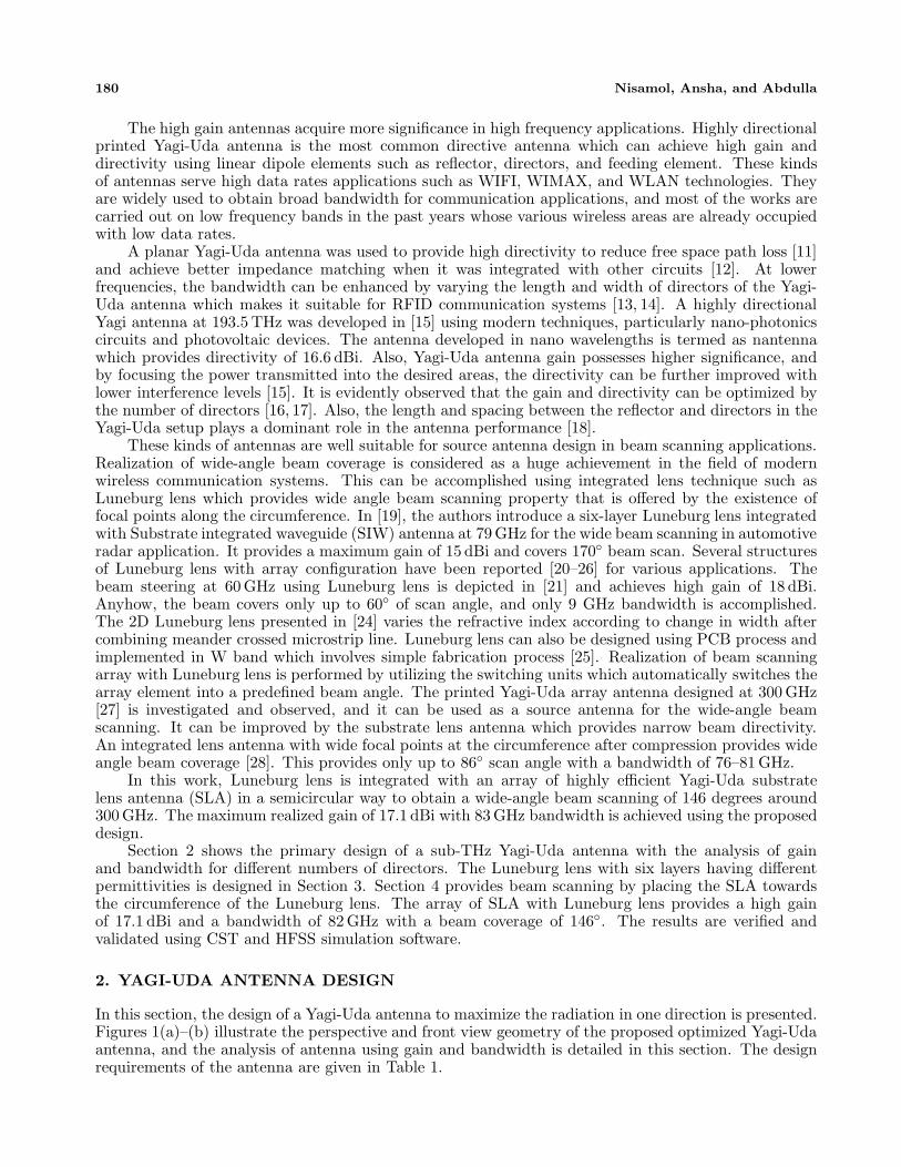
Table 3. The optimized dimensions of the Yagi-Uda antenna.
Dimensions ValuesW 300 µmL 575 µmR 300 µmLd 272 µmSd 5µmD1 220 µmD2 200 µmD3 190 µmD4 180 µmD5 170 µmD6 162 µm
01.22.43.64.867.28.49.610.812
05
101520253035404550
0 2 4 6 8 10
Gai
n (d
Bi)
Ban
dwid
th (
dB)
Number of directors
Bandwidth (GHz)
Gain (dB)
Figure 2. The optimization of gain andbandwidth with different numbers of directors.
012345678910
-45
-40
-35
-30
-25
-20
-15
-10
-5
0
290 300 310 320 330 340 350
Gai
n (d
Bi)
Ret
urn
loss
(dB
)
Frequency (GHz)
Return lossGain
Figure 3. The gain and S parameter analysis ofYagi-Uda antenna in CST suite.
(a) (b)
Figure 4. 3D far-field radiation pattern at 300 GHz. (a) Gain. (b) Directivity.
Progress In Electromagnetics Research C, Vol. 99, 2020 183
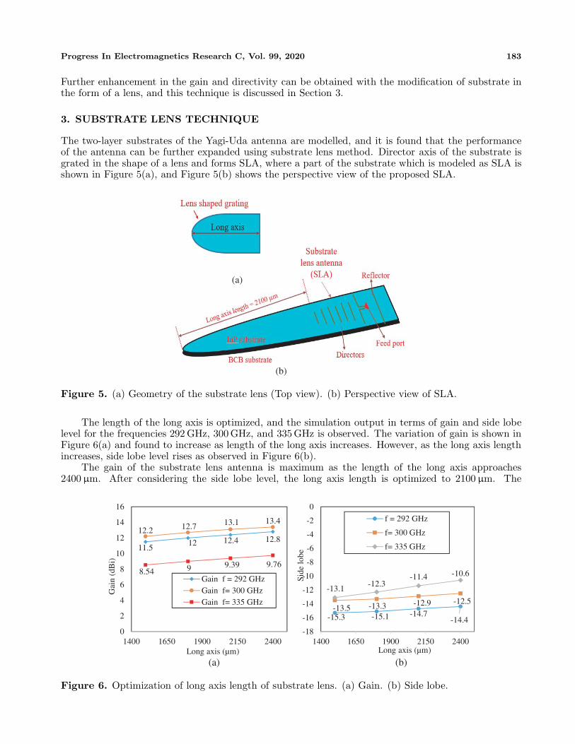
Further enhancement in the gain and directivity can be obtained with the modification of substrate inthe form of a lens, and this technique is discussed in Section 3.
3. SUBSTRATE LENS TECHNIQUE
The two-layer substrates of the Yagi-Uda antenna are modelled, and it is found that the performanceof the antenna can be further expanded using substrate lens method. Director axis of the substrate isgrated in the shape of a lens and forms SLA, where a part of the substrate which is modeled as SLA isshown in Figure 5(a), and Figure 5(b) shows the perspective view of the proposed SLA.
(a)
(b)
Figure 5. (a) Geometry of the substrate lens (Top view). (b) Perspective view of SLA.
The length of the long axis is optimized, and the simulation output in terms of gain and side lobelevel for the frequencies 292 GHz, 300 GHz, and 335 GHz is observed. The variation of gain is shown inFigure 6(a) and found to increase as length of the long axis increases. However, as the long axis lengthincreases, side lobe level rises as observed in Figure 6(b).
The gain of the substrate lens antenna is maximum as the length of the long axis approaches2400 µm. After considering the side lobe level, the long axis length is optimized to 2100 µm. The
(a) (b)
11.512 12.4 12.8
12.2 12.7 13.1 13.4
8.54 9 9.39 9.76
0
2
4
6
8
10
12
14
16
1400 1650 1900 2150 2400
Gai
n (d
Bi)
Long axis (µm)
Gain f = 292 GHzGain f= 300 GHzGain f= 335 GHz
-15.3 -15.1 -14.7-14.4
-13.5 -13.3 -12.9 -12.5
-13.1-12.3
-11.4 -10.6
-18
-16
-14
-12
-10
-8
-6
-4
-2
0
1400 1650 1900 2150 2400
Side
lobe
Long axis (µm)
f = 292 GHz
f= 300 GHz
f= 335 GHz
Figure 6. Optimization of long axis length of substrate lens. (a) Gain. (b) Side lobe.
184 Nisamol, Ansha, and Abdulla
0
3
6
9
11
14
17
20
-35
-30
-25
-20
-15
-10
-5
0
250 275 300 325 350 375 400
Gai
n (d
Bi)
Ret
urn
loss
(dB
)
Frequency (GHz)
CST-S_11 HFSS_S_11CST_GAIN HFSS_GAIN
Figure 7. Simulated S parameter and gain plot.
(a) (b)
Figure 8. 3D far-field radiation pattern of substrate lens antenna. (a) Gain. (b) Directivity.
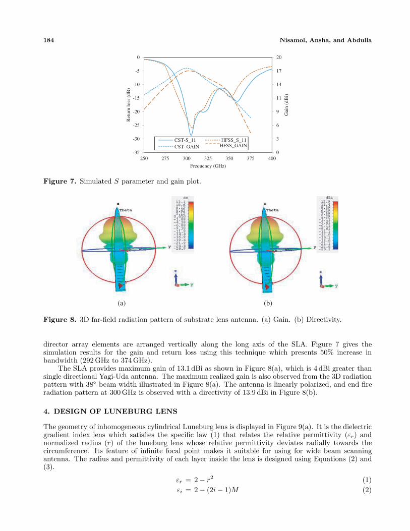
director array elements are arranged vertically along the long axis of the SLA. Figure 7 gives thesimulation results for the gain and return loss using this technique which presents 50% increase inbandwidth (292 GHz to 374 GHz).
The SLA provides maximum gain of 13.1 dBi as shown in Figure 8(a), which is 4 dBi greater thansingle directional Yagi-Uda antenna. The maximum realized gain is also observed from the 3D radiationpattern with 38◦ beam-width illustrated in Figure 8(a). The antenna is linearly polarized, and end-fireradiation pattern at 300 GHz is observed with a directivity of 13.9 dBi in Figure 8(b).
4. DESIGN OF LUNEBURG LENS
The geometry of inhomogeneous cylindrical Luneburg lens is displayed in Figure 9(a). It is the dielectricgradient index lens which satisfies the specific law (1) that relates the relative permittivity (εr) andnormalized radius (r) of the luneburg lens whose relative permittivity deviates radially towards thecircumference. Its feature of infinite focal point makes it suitable for using for wide beam scanningantenna. The radius and permittivity of each layer inside the lens is designed using Equations (2) and(3).
εr = 2 − r2 (1)εi = 2 − (2i − 1)M (2)

Progress In Electromagnetics Research C, Vol. 99, 2020 185
(a) (b)
Figure 9. Structure of Luneburg lens. (a) Side view before compression. (b) Top view aftercompression.
ri = (2 − εi + M)1/2 (3)
Six-layer Luneburg lens is designed by using these equations having outer diameter of 3λ0, whereλ0 is the free space wavelength at frequency of 300 GHz. Thickness of the optimized lens is chosen tobe 224 µm. Table 4 shows the height and radius of each layer before compression.
Table 4. The geometry of the Luneburg lens.
Height of lens (µm) Outer radius (µm)
Layer-1 820 1140
Layer-2 646 1040
Layer-3 789 931
Layer-4 634 806
Layer-5 618 660
Layer-6 803 465
The basic foam material such as AirexR82 with εr 1.12 and thickness 224 µm is utilized for thedevelopment of Luneburg lens. To obtain different values of relative permittivity at required areasand to have final thickness of 224 µm, the basic foam material is pressed in a controlled manner ata fixed temperature of 90◦C. The air bubbles that are filled inside the foam material are removed atthis temperature setup. The dielectric constant of the pressed foam can be controlled in the design bychoosing the optimum area density ratio given in Eq. (4),
ξ =Hi
Hf(4)
where Hi is the initial foam thickness, and Hf is the final foam thickness after compression. The heightof all the layers shrinks to 224 µm. The variation of radius and permittivity of each layer is depicted inTable 5. Figure 9(b) illustrates the top view of Luneburg lens after compression.
To achieve the design of the lens with different areas having different thicknesses, cylindrical shapedbasic foam material is drilled in a 2D mechanical process, and its dielectric constant and loss tangentare measured in characterization free space measurement setup which consists of AB millimeter VNAand lens horn antennas [17].

186 Nisamol, Ansha, and Abdulla
Table 5. Final designed Luneburg lens properties for different ε.
ξ = Hi/Hf Hi (mm) Hf (mm) Relative permittivity Loss tangent8 28 224 1.92 0.015
6.5 22.75 224 1.77 0.0145.35 18.725 224 1.62 0.0134.2 14.7 224 1.46 0.012.75 9.625 224 1.31 0.0081.5 5.25 224 1.15 0.007
5. PROPOSED 9 ELEMENT SLA ARRAY WITH LUNEBURG LENS
Figure 10 shows the single SLA integrated with Luneburg lens at its circumference to obtain an increasein the gain of 4.7 dBi compared to single source antenna. The maximum gain of 17.7 dBi with abandwidth of 82 GHz (from 291 GHz to 373 GHz) at the center frequency of 300 GHz is observed fromFigure 11(a) and verified using HFSS. The simulated 2D co-polar radiation pattern of single SLAwith Luneburg lens in CST microwave studio suite is observed in Figure 11(b) which shows narrowbeamwidth of 17.3◦, and the result is verified using commercially available electromagnetic simulationsoftware HFSS due to the lack of fabrication and measurement facility at the simulated laboratory. Thesimilarity between the simulated co-polar radiation patterns on two different algorithms in Figure 11(b)are validated by using the feature selective validation (FSV) tool [29–31], and feature difference measure(FDM) chart [31] is shown in Figure 11(c). The good and fairly similar results from both software raisethe accuracy level of measurement outcome. The maximum gain is obtained at 0◦ beam shift andpossesses minimum side lobe level of −15.94 dBi.
6 element compressedLuneburg lens
Yagi-Uda substrate lens antenna
0.806 mm
Figure 10. The single substrate lens Yagi-Uda antenna integrated with Luneburg lens.
The array of SLA is integrated with Luneburg lens as shown in Figure 12 in order to achieve beamscanning. Utilizing the existence of several focusing points at the circumference of the Luneburg lens,the final antenna achieves a wide-angle beam scanning in the azimuth plane. The simulated matchedreturn loss with maximum bandwidth of 83 GHz which ranges from 289 GHz to 372 GHz at 300 GHzcenter frequency is shown in Figure 13(a). The 2D co-polar far-field radiation pattern of the finalstructure with one SLA illuminated at a time is illustrated in Figure 13(b), and the simulation resultsare verified using HFSS software. The spacing between the SLA and Luneburg lens is optimized to
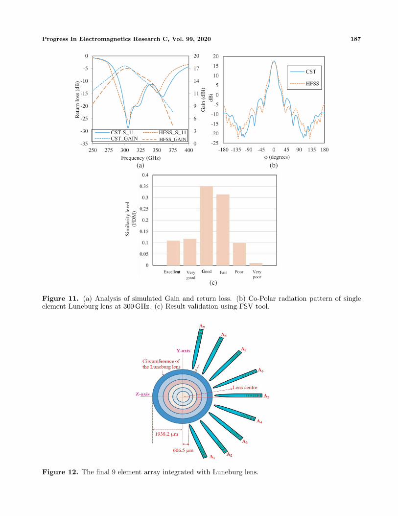
Progress In Electromagnetics Research C, Vol. 99, 2020 187
-25
-20
-15
-10
-5
0
5
10
15
20
-180 -135 -90 -45 0 45 90 135 180
dBi
ϕ (degrees)
CST
HFSS
0
3
6
9
11
14
17
20
-35
-30
-25
-20
-15
-10
-5
0
250 275 300 325 350 375 400
Gai
n (d
Bi)
Ret
urn
loss
(dB
)
Frequency (GHz)
CST-S_11 HFSS_S_11CST_GAIN HFSS_GAIN
Excellent Fair Good Very good
Poor Very poor
Sim
ilari
ty le
vel
(FD
M)
(a) (b)
(c)
Figure 11. (a) Analysis of simulated Gain and return loss. (b) Co-Polar radiation pattern of singleelement Luneburg lens at 300 GHz. (c) Result validation using FSV tool.
Figure 12. The final 9 element array integrated with Luneburg lens.

188 Nisamol, Ansha, and Abdulla
-45
-40
-35
-30
-25
-20
-15
-10
-5
0
250 280 310 340 370 400
Ret
urn
loss
(dB
)
Frequency (GHz)
S_11S_22S_33S_44S_55S_66S_77S_88S_99
300 GHz matching at each feed
A5 A4 A9 A7 A3 A2 A1 A6 A8
(a) (b)
Figure 13. (a) Simulated matched return loss of Final 9-array Yagi-Uda antenna with Luneburg lensilluminating one Yagi antenna at a time. (b) Verification of co-polar beam scanning radiation patternusing CST and HFSS at 300 GHz.
(a) (b)
(c)
Figure 14. E-field distribution. (a) A9 is energized. (b) A5 is energized. (c) A1 is energized.
72 µm and possesses tolerable geometric spacing from 72 µm to 92 µm without adverse effect in thereflection and radiation characteristics.
Each element in the SLA array is denoted by A1, A2, A3, A4, A5, A6, A7, A8, and A9 with centerSLA as A5. The nine SLA elements are excited separately, and center SLA element provides a radiationpattern without any deviation from ϕ = 0◦. The elements at the edges represented by A1 and A9 havea beam shift of +73◦ and −73◦, respectively. Thereby, the proposed antenna using the 9-element arraysetup has a wide beam coverage of 146◦ with a maximum gain of 17.2 dBi observed between the feedports at A1 to A9. The array elements A1, A2, A3, and A4 provide the maximum gain towards theangles 73◦, 55◦, 35◦, and 17.2◦, respectively. Thus, the beam can cover up to 73◦ towards the positivescan angle using the 4-element array with a beamwidth of 17.3◦.
Similarly, maximum radiation is obtained at 17.2◦, 35◦, 55◦, and 73◦ when exciting the arrayelements A6, A7, A8, and A9, respectively. The electric field distribution pattern (at 300 GHz) of thearray antenna where 3 elements at A1, A5, and A9 are excited, and others are terminated by 50 Ω loadis shown in Figures 14(a)–(c).
Maximum gain is obtained when the center source element (i.e., A5) is energized as in Figure 14(b),and minimum gain is obtained when the elements at the edges such as A1 and A9 are energized. Thegain reduction is due to the encounter of radiation from the SLA at the two edge feeds. The total
Progress In Electromagnetics Research C, Vol. 99, 2020 189
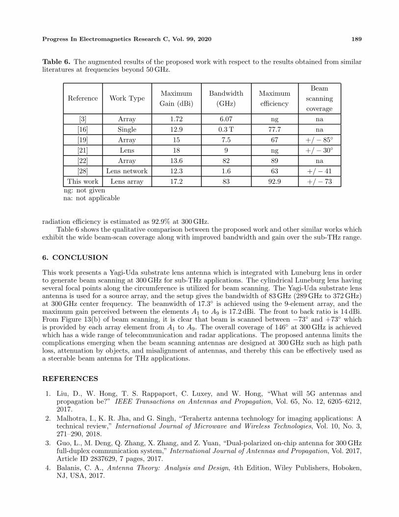
Table 6. The augmented results of the proposed work with respect to the results obtained from similarliteratures at frequencies beyond 50 GHz.
Reference Work TypeMaximumGain (dBi)
Bandwidth(GHz)
Maximumefficiency
Beamscanningcoverage
[3] Array 1.72 6.07 ng na[16] Single 12.9 0.3 T 77.7 na[19] Array 15 7.5 67 +/ − 85◦
[21] Lens 18 9 ng +/ − 30◦
[22] Array 13.6 82 89 na[28] Lens network 12.3 1.6 63 +/ − 41
This work Lens array 17.2 83 92.9 +/ − 73ng: not givenna: not applicable
radiation efficiency is estimated as 92.9% at 300 GHz.Table 6 shows the qualitative comparison between the proposed work and other similar works which
exhibit the wide beam-scan coverage along with improved bandwidth and gain over the sub-THz range.
6. CONCLUSION
This work presents a Yagi-Uda substrate lens antenna which is integrated with Luneburg lens in orderto generate beam scanning at 300 GHz for sub-THz applications. The cylindrical Luneburg lens havingseveral focal points along the circumference is utilized for beam scanning. The Yagi-Uda substrate lensantenna is used for a source array, and the setup gives the bandwidth of 83 GHz (289 GHz to 372 GHz)at 300 GHz center frequency. The beamwidth of 17.3◦ is achieved using the 9-element array, and themaximum gain perceived between the elements A1 to A9 is 17.2 dBi. The front to back ratio is 14 dBi.From Figure 13(b) of beam scanning, it is clear that beam is scanned between −73◦ and +73◦ whichis provided by each array element from A1 to A9. The overall coverage of 146◦ at 300 GHz is achievedwhich has a wide range of telecommunication and radar applications. The proposed antenna limits thecomplications emerging when the beam scanning antennas are designed at 300 GHz such as high pathloss, attenuation by objects, and misalignment of antennas, and thereby this can be effectively used asa steerable beam antenna for THz applications.
REFERENCES
1. Liu, D., W. Hong, T. S. Rappaport, C. Luxey, and W. Hong, “What will 5G antennas andpropagation be?” IEEE Transactions on Antennas and Propagation, Vol. 65, No. 12, 6205–6212,2017.
2. Malhotra, I., K. R. Jha, and G. Singh, “Terahertz antenna technology for imaging applications: Atechnical review,” International Journal of Microwave and Wireless Technologies, Vol. 10, No. 3,271–290, 2018.
3. Guo, L., M. Deng, Q. Zhang, X. Zhang, and Z. Yuan, “Dual-polarized on-chip antenna for 300 GHzfull-duplex communication system,” International Journal of Antennas and Propagation, Vol. 2017,Article ID 2837629, 7 pages, 2017.
4. Balanis, C. A., Antenna Theory: Analysis and Design, 4th Edition, Wiley Publishers, Hoboken,NJ, USA, 2017.

190 Nisamol, Ansha, and Abdulla
5. Ismail, M. Y. and N. H. Sulaiman, “Enhanced bandwidth reflectarray antenna using variable dualgap,” International Conference on Instrumentation, Communication, Information Technology andBiomedical Engineering, IEEE, Bandung, Indonesia, 2011.
6. Florencio, R., R. R. Boix, and J. A. Encinar, “Design of a reflectarray antenna at 300 GHz basedon cells with three coplanar dipoles,” 2013 IEEE Antennas and Propagation Society InternationalSymposium (APSURSI), IEEE, 2013.
7. Munoz-Acevedo, A., M. Sierra-Castaner, and J. L. Besada, “Antenna measurement system at300 GHz for the terasense project,” Proceedings of the Fourth European Conference on Antennasand Propagation, 1–5, 2010.
8. Rey, S., T. Merkle, A. Tessmann, and T. Kurner, “A phased array antenna with horn elements for300 GHz communications,” Proceedings of ISAP-2016, 122–123, IEEE, Okinawa, Japan, 2016.
9. Azizi, M. K., M. A. Ksiksi, H. Ajlani, and A. Gharsallah, “Terahertz graphene-based reconfigurablepatch antenna,” Progress In Electromagnetics Research Letters, Vol. 71, 69–76, 2017.
10. Chen, J., K. Yuan, L. Shen, X. Deng, L. Hong, and M. Yao, “Studies of terahertz wave propagationin realistic reentry plasma sheath,” Progress In Electromagnetics Research, Vol. 157, 21–29, 2016.
11. Priebe, S., C. Jastrow, M. Jacob, T. Kleine-Ostmann, T. Schrader, and T. Kurner, “Channel andpropagation measurements at 300 GHz,” IEEE Transactions on Antennas and Propagation, Vol. 59,No. 5, May 2011.
12. Bankey, V. and N. Anvesh Kumar, “Design of a Yagi-Uda antenna with gain and bandwidthenhancement for Wi-Fi and Wi-Max applications,” International Journal of Antennas (JANT),Vol. 2, No. 1, 1–14, January 2016.
13. Cai, R.-N., Y. Chuan, L. Shu, X.-Q. Zhang, X.-Y. Zhang, and X.-F. Liu, “Design and analysis ofprinted Yagi-Uda antenna and two-element array for WLAN applications,” International Journalof Antennas and Propagation, Article Id 651789, 8 Pages, 2012.
14. Han, K., T. K. Nguyen, and I. Park, “Yagi-Uda antenna with U-shaped dipole for a THzphotomixer,” 34th International Conference on Infrared, Millimeter, and Terahertz Waves, 2009.
15. Mathew, P. K., “A three element Yagi Uda antenna for RFID systems,” IJEDR, Vol. 2, No. 1,ISSN: 2321–9939, 2014.
16. Sethi, W. T., O. De Sagazan, H. Vettikalladi, H. Fathallah, and M. Himdi, “Yagi-Uda nantennafor 1550 nanometers optical communication systems,” International Journal of Antennas andPropagation, Vol. 60, No. 9, 2236–2242, 2018.
17. Sharma, Y. and S. Nagpal, “Radiation pattern optimization of a 6 element Yagi-Uda antenna,”IJREST International Journal of Research Review In Engineering Science & Technology, Vol. 5,No. 1, Issn 2278–6643, 2016.
18. Prasada Reddy, M., “Directional Yagi Uda antenna for VHF applications,” International Journalof Advancements in Technology, Vol. 9, No. 3, Issn: 0976–4860, 2018.
19. Kamran Saleem, M., H. Vettikaladi, M. A. S. Alkanhal, and M. Himdi, “Lens antenna for wideangle beam scanning at 79 GHz for automotive short range radar applications,” IEEE Transactionson Antennas and Propagation, Vol. 65, No. 4, 2041–2046, Apr. 2017.
20. Rondineau, S., M. Himdi, and J. Sorieux, “A sliced spherical Luneburg lens,” IEEE Antennas andWireless Propagation Letters, Vol. 2, 163–166, 2003.
21. Foster, R., D. Nagarkoti, J. Gao, B. Vial, F. Nicholls, C. Spooner, S. Haq, and Y. Hao,“Beam-steering performance of flat Luneburg lens at 60 GHz for future wireless communications,”International Journal of Antennas and Propagation, Article Id 7932434, 8 pages, 2017.
22. Vettikalladi, H., W. T. Sethi, A. F. Bin Abas, W. Ko, M. A. Alkanhal, and M. Himdi, “Sub-THzantenna for high-speed wireless communication systems,” International Journal of Antennas andPropagation, Article ID 9573647, 9 pages, 2019.
23. Knyazev, S., A. Korotkov, B. Panchenko, and S. Shabunin, “Investigation of spherical andcylindrical Luneburg lens antennas by the Green’s function method,” IEEE Radio and AntennaDays of the Indian Ocean, IEEE Radio, 2015.
Progress In Electromagnetics Research C, Vol. 99, 2020 191
24. Zhou, B., Y. Yang, H. Li, and T. J. Cui, “Beam-steering Vivaldi antenna based on partial Luneburglens constructed with composite materials,” Journal of Applied Physics, Vol. 110, 084908, 2011.
25. Chen, H., Q. Cheng, A. Huang, J. Dai, H. Lu, J. Zhao, H. Ma, W. Jiang, and T. J. Cui, “ModifiedLuneburg lens based on metamaterials,” International Journal of Antennas and Propagation,Article Id 902634, 6 pages, 2015.
26. Liang, M., W.-R. Ng, K. Chang, K. Gbele, M. E. Gehm, and H. Xin, “A 3-D Luneburg lensantenna fabricated by polymer jetting rapid prototyping,” IEEE Transactions on Antennas andPropagation, Vol. 62, No. 4, 1799–1807, 2014.
27. Pfeiffer, C. and A. Grbic, “A printed, broadband Luneburg lens antenna,” IEEE Transactions onAntennas and Propagation, Vol. 58, No. 9, 3055–3059, 2010.
28. Numan, A. B., J.-F. Frigon, and J.-J. Laurin, “Printed W-band multibeam antenna with Luneburglens-based beamforming network,” IEEE Transactions on Antennas and Propagation, Vol. 66,No. 10, 5614–5619, 2018.
29. IEEE Standard P1597, “Standard for validation of computational electromagnetics computermodeling and simulation — Part 1, 2,” 2008.
30. Duffy, A. P., A. J. M. Martin, A. Orlandi, G. Antonini, T. M. Benson, and M. S. Woolfson, “Featureselective validation (FSV) for validation of computational electromagnetics (CEM). Part I — TheFSV method,” IEEE Trans. on Electromagn. Compatibility, Vol. 48, No. 3, 449–459, Aug. 2006.
31. Orlandi, A., A. P. Duffy, B. Archambeault, G. Antonini, D. E. Coleby, and S. Connor, “Featureselective validation (FSV) for validation of computational electromagnetics (CEM). Part II —Assessment of FSV performance,” IEEE Trans. on Electromagn. Compatibility, Vol. 48, No. 3,460–467, Aug. 2006.


![Patch Antenna[1]](https://static.fdokumen.com/doc/165x107/63158e4cc32ab5e46f0d5c89/patch-antenna1.jpg)


