Design of Solar Pond calculation and technique in Africa - IOSR Journal
11
IOSR Journal of Mechanical and Civil Engineering (IOSR-JMCE) e-ISSN: 2278-1684 Volume 6, Issue 1 (Mar. - Apr. 2013), PP 22-32 www.iosrjournals.org www.iosrjournals.org 22 | Page Design of Solar Pond calculation and technique in Africa Jerome Godwin Egbe, Ahmed Hassan Khan, Wongsakorn Wisatesajja 1( Civil Engineering Department/Cross River University of Technology, Nigeria) 2( Chemical & Process Engineering/University of Surrey, Pakistan) 3( Chemical &Process Engineering Department /University of Surrey, Thailand) Abstract: Extracting energy from the sun has revolutionized the global energy industry. Different literatures have been reviewed to give an appropriate theory and mathematical model for the design of solar pond in Africa.The location chosen is Cairo,Egypt due to high annual solar radiation,feasible land, and fresh water conditions and cost effective. Energy balance equations have been computed from different case studies to show the factors affecting the efficiency of the solar pond such as effect of density, temperature, solar radiation, insulation thickness and depth of different layers .Optimum conditions for the design of a solar pond have been determined such as the thickness of the upper layer should not be more than 0.3m whereas the optimum thickness of gradient zone should be1-1.5m and the storage zone should be 1-4m.The main constraints in the design of a solar pond are different heat losses.But however, different techniques have been discussed for reducing the heat losses such as black painted concrete slab and concrete walls for minimizing the bottom losses and using a polystyrene top cover for reducing evaporation losses during night, winters and autumn. This technique can be very useful for the people of Africa specially dwelling in rural areas . Keywords: Design, Solar Pond,RenewableEnergy I. Introduction Global warming could be one of the world‟s most important issues in the 21 st century [13].Every year, billions of tonnes of carbon dioxide have been emitted into the global atmosphere[1].Global warming mainly occurs due to human activities such as transportation, producing electricity and in industries which involves burning fossil fuels[2], which could lead to a significant decrease in world fossil fuels reserves[3].However, renewable energy technologies have been developed and introduced as an alternative source for energy production; renewable energy technology can produce energy with zero carbon dioxide emissions, unlimited sources and benefits the economy[11]. Solar energy is one of the essential world renewable energy sources. The conversion of the energy can be operated by several techniques such as photovoltaic systems for producing electricity and solar hot water for heating water with solar energy. Solar ponds have been suggested to be simple and economical in terms of collecting and storing energy on a large scale. There are two types of solar ponds depending on the convecting behaviors and the non- convecting solar ponds [4]. The location of a non-convecting solar pond is at Cairo, Egypt (30.0566 ° N, 31.2262°E). Based on the NASA websites, Egypt has abundant sunshine with an annual average solar irradiationabout 5.35 kWh/m 2 /day [6]. The objective of this work is to provide the appropriate theory, cost estimation, design reality, specification and calculation details such as temperature effect,radiation effect, depth effect, density effect and the produced temperature of the pond. This report has been divided into different chapters with background in Chapter 2.An appropriate theory for this task is expanded in the chapter 3.The design and detailed mathematical model for the task is explained in chapter 3& 4 respectively. Chapter 5 deals with the values of different parameters and results of different factors affecting the efficiency of the solar pond, cost estimation, and conclusion of the project are described. Finally, the number and detail of references used for the report are also listed. In the seventies when the oil crisis occurred and also later through the eighties, much research and development was on the potential of using a solar pond as an alternative power generating. Solar ponds are controlled body of water that collects and stores solar energy.Solar ponds neither use tracking systems such as mirror, nor do they concentrate the sun‟s rays like other solar technologies. Ponds can be naturally occurring, however most ponds in Africa or the world at large, are man-made. II. Theory The“fig.”1.Shows the salt-water solar pond, which the amount of salts dissolved in the water, has increased with depth. Therefore, the salinity and density of each layer in the pond would also be increased with depth, so it is called a salt stabilized or salinity-gradient solar pond. The layer below salinity-gradient zone is called storage zone which can be defined as saturated salt solution, and above salinity-gradient zone which the
-
Upload
khangminh22 -
Category
Documents
-
view
1 -
download
0
Transcript of Design of Solar Pond calculation and technique in Africa - IOSR Journal

IOSR Journal of Mechanical and Civil Engineering (IOSR-JMCE)
e-ISSN: 2278-1684 Volume 6, Issue 1 (Mar. - Apr. 2013), PP 22-32 www.iosrjournals.org
www.iosrjournals.org 22 | Page
Design of Solar Pond calculation and technique in Africa
Jerome Godwin Egbe, Ahmed Hassan Khan, Wongsakorn Wisatesajja 1(Civil Engineering Department/Cross River University of Technology, Nigeria)
2(Chemical & Process Engineering/University of Surrey, Pakistan)3(Chemical &Process Engineering
Department /University of Surrey, Thailand)
Abstract: Extracting energy from the sun has revolutionized the global energy industry. Different literatures
have been reviewed to give an appropriate theory and mathematical model for the design of solar pond in
Africa.The location chosen is Cairo,Egypt due to high annual solar radiation,feasible land, and fresh water
conditions and cost effective. Energy balance equations have been computed from different case studies to show
the factors affecting the efficiency of the solar pond such as effect of density, temperature, solar radiation,
insulation thickness and depth of different layers .Optimum conditions for the design of a solar pond have been
determined such as the thickness of the upper layer should not be more than 0.3m whereas the optimum
thickness of gradient zone should be1-1.5m and the storage zone should be 1-4m.The main constraints in the
design of a solar pond are different heat losses.But however, different techniques have been discussed for
reducing the heat losses such as black painted concrete slab and concrete walls for minimizing the bottom
losses and using a polystyrene top cover for reducing evaporation losses during night, winters and autumn. This
technique can be very useful for the people of Africa specially dwelling in rural areas.
Keywords: Design, Solar Pond,RenewableEnergy
I. Introduction Global warming could be one of the world‟s most important issues in the 21st century [13].Every year,
billions of tonnes of carbon dioxide have been emitted into the global atmosphere[1].Global warming mainly
occurs due to human activities such as transportation, producing electricity and in industries which involves
burning fossil fuels[2], which could lead to a significant decrease in world fossil fuels reserves[3].However,
renewable energy technologies have been developed and introduced as an alternative source for energy
production; renewable energy technology can produce energy with zero carbon dioxide emissions, unlimited sources and benefits the economy[11].
Solar energy is one of the essential world renewable energy sources. The conversion of the energy can
be operated by several techniques such as photovoltaic systems for producing electricity and solar hot water for
heating water with solar energy. Solar ponds have been suggested to be simple and economical in terms of
collecting and storing energy on a large scale. There are two types of solar ponds depending on the convecting
behaviors and the non- convecting solar ponds [4].
The location of a non-convecting solar pond is at Cairo, Egypt (30.0566 ° N, 31.2262°E). Based on the NASA
websites, Egypt has abundant sunshine with an annual average solar irradiationabout 5.35 kWh/m2/day [6].
The objective of this work is to provide the appropriate theory, cost estimation, design reality, specification and
calculation details such as temperature effect,radiation effect, depth effect, density effect and the produced
temperature of the pond.
This report has been divided into different chapters with background in Chapter 2.An appropriate theory for this task is expanded in the chapter 3.The design and detailed mathematical model for the task is
explained in chapter 3& 4 respectively. Chapter 5 deals with the values of different parameters and results of
different factors affecting the efficiency of the solar pond, cost estimation, and conclusion of the project are
described. Finally, the number and detail of references used for the report are also listed.
In the seventies when the oil crisis occurred and also later through the eighties, much research and development
was on the potential of using a solar pond as an alternative power generating. Solar ponds are controlled body of
water that collects and stores solar energy.Solar ponds neither use tracking systems such as mirror, nor do they
concentrate the sun‟s rays like other solar technologies. Ponds can be naturally occurring, however most ponds
in Africa or the world at large, are man-made.
II. Theory The“fig.”1.Shows the salt-water solar pond, which the amount of salts dissolved in the water, has
increased with depth. Therefore, the salinity and density of each layer in the pond would also be increased with
depth, so it is called a salt stabilized or salinity-gradient solar pond. The layer below salinity-gradient zone is
called storage zone which can be defined as saturated salt solution, and above salinity-gradient zone which the

Design of Solar Pond calculation and technique in Africa
www.iosrjournals.org 23 | Page
layer of fresh or low-salinity water, it is called the surface zone. The thickness of storage zone is normally
around one or two meters, the surface zone is around 0.3 meters and the overall pond should be around two or
more meters [1]. If the solar ponds have suitable gradient of salt concentration at the storage zone and clear fresh water
at surface zone. Therefore, the solar energy would be absorbed and collected by the storage zone, which salt
water will not rise when it has been heated due to the salt water is heavier than the fresh water on the surface
zone. Then the surface zone acts as an insulating blanket and temperature at the storage zone could reach up to
90°C [2]. This temperature is high enough to generate a vapour cycle engine to generate the electricity.
Solar Ponds can be used for different applications. Process Heat, Solar ponds can be used for heating purposes
in many ways such as Process Industries, Domestic & Commercial Heating Systems in colder countries,
Thermal Electricity desalination. Solar Ponds can play an efficient role in providing clean drinking water
refrigeration
Fig.1.Theschematic representation of salinitygradient solar pond[1].
III. Designs 3.1 Land
Salinity gradient solar ponds become more economical when their sizes are approximately 10,000 to
100,000 m2. The feasibility of the Land/Site depends on various factors which can be summarized as, having flat
Land to minimize earth moving requirements. Dry Soil for good thermal insulation.
All these conditions are related to each other in some way or another and we have to compromise on some of the
conditions and look for a site with minimum losses for instance a high solar radiation means high evaporation
losses. Therefore, we have chosen Cairo in Egypt which has a flat land and the soil is feasible for constructing
a solar pond. And our site is near the River Nile in the out skirts of Cairo. The solar pond area is 100 x 100m.
The thickness of the surface zone, gradient zone and storage zone are 0.3, 1.0 and 1.5m respectively. The pond
shape is square.
3.2Insulation
The bottom of the pond isinsulated with sheets of polystyrene. For choosing the insulation material
following properties should be observed:
It should withstand the maximum temperature anticipated in the pond.
It should be resistant to ultraviolet radiations.
It should not react with the salt.
3.3Salt-Water Sources
Sodium chloride (NaCl) will be used. The aqueous solutions of NaCl can attain maximum density of
1200 kg/m3[1].
3.4 Water sources
Sodium chloride (NaCI) will be used. The aqueous solutions of NaCI can attain maximum density of
1200kg/m3[1].
Availability of fresh water with low salinity is one of the most important features of a solar pond. So that the
amount of salt may be added according to the application for which the solar pond is being designed [1].
Design of Solar Pond calculation and technique in Africa
www.iosrjournals.org 24 | Page
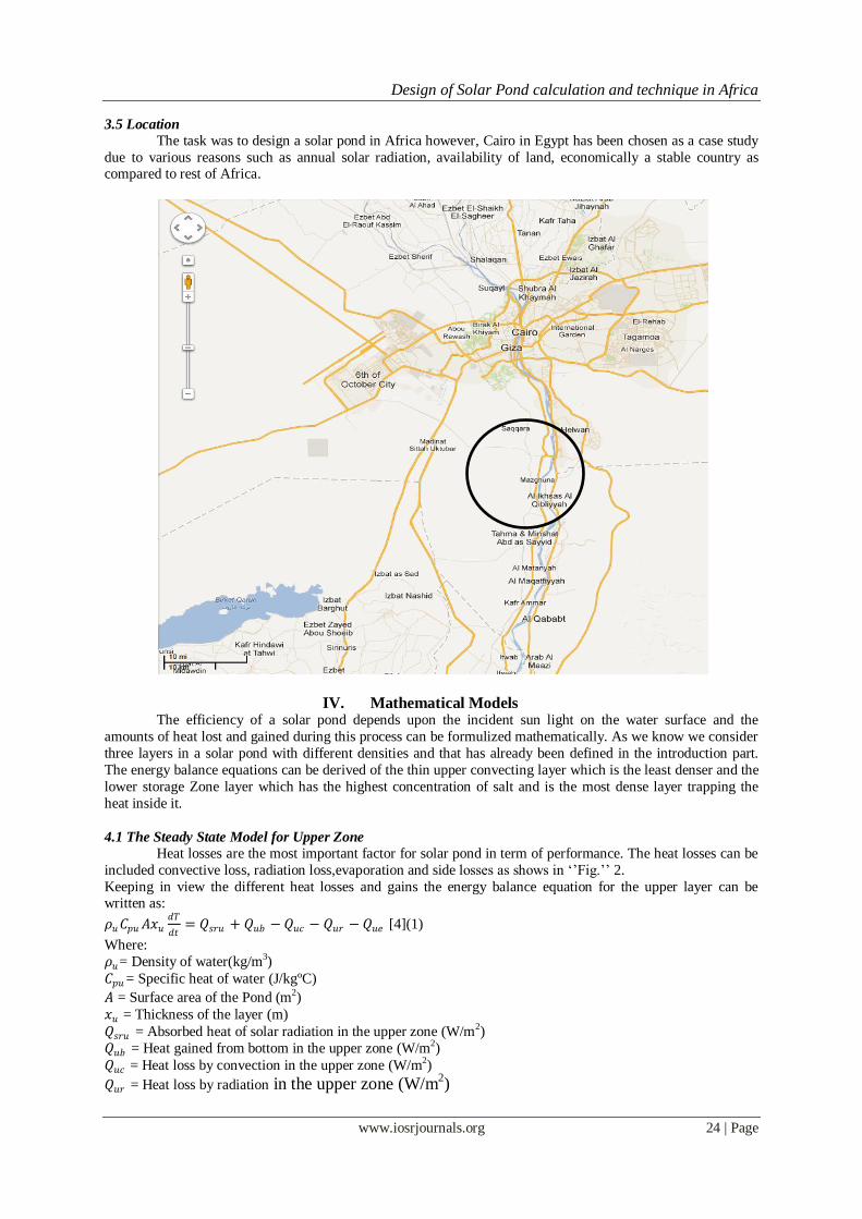
3.5 Location
The task was to design a solar pond in Africa however, Cairo in Egypt has been chosen as a case study
due to various reasons such as annual solar radiation, availability of land, economically a stable country as compared to rest of Africa.
IV. Mathematical Models The efficiency of a solar pond depends upon the incident sun light on the water surface and the
amounts of heat lost and gained during this process can be formulized mathematically. As we know we consider
three layers in a solar pond with different densities and that has already been defined in the introduction part.
The energy balance equations can be derived of the thin upper convecting layer which is the least denser and the
lower storage Zone layer which has the highest concentration of salt and is the most dense layer trapping the
heat inside it.
4.1 The Steady State Model for Upper Zone
Heat losses are the most important factor for solar pond in term of performance. The heat losses can be
included convective loss, radiation loss,evaporation and side losses as shows in „‟Fig.‟‟ 2.
Keeping in view the different heat losses and gains the energy balance equation for the upper layer can be written as:
𝜌𝑢𝐶𝑝𝑢𝐴𝑥𝑢𝑑𝑇
𝑑𝑡= 𝑄𝑠𝑟𝑢 + 𝑄𝑢𝑏 −𝑄𝑢𝑐 − 𝑄𝑢𝑟 −𝑄𝑢𝑒 [4](1)
Where:
𝜌𝑢= Density of water(kg/m3)
𝐶𝑝𝑢= Specific heat of water (J/kgºC)
𝐴 = Surface area of the Pond (m2)
𝑥𝑢 = Thickness of the layer (m)
𝑄𝑠𝑟𝑢 = Absorbed heat of solar radiation in the upper zone (W/m2)
𝑄𝑢𝑏 = Heat gained from bottom in the upper zone (W/m2)
𝑄𝑢𝑐 = Heat loss by convection in the upper zone (W/m2)
𝑄𝑢𝑟 = Heat loss by radiation in the upper zone (W/m2)

Design of Solar Pond calculation and technique in Africa
www.iosrjournals.org 25 | Page
𝑄𝑢𝑒 = Heat loss by evaporation in the upper zone (W/m2)
𝑄𝑢𝑤 = Heat loss from the sides in the upper zone (W/m2)
Fig.2.Heat balance in the Upper zone [4].
4.2 Absorbed Heat in the Upper Layer from Solar Radiation, Qsru
The amount of absorbed solar radiation in the upper zone of a pond can be estimated according to the
amount of the solar beam attenuation at depth x.
𝑄𝑠𝑟𝑢𝑖 = 𝜏𝐴𝑅 (2)
𝑄𝑠𝑟𝑢𝑜 = 𝜏𝐴𝑢𝑅 𝜂𝑛𝑒−𝜇𝑛 𝑥𝑢 / cos 𝑟4
𝑛=1 (3)
𝑄𝑠𝑟𝑢 = 𝑄𝑠𝑟𝑢𝑖−𝑄𝑠𝑟𝑢𝑜 (4)
Where:
𝑄𝑠𝑟𝑢𝑖 = Input solar radiation to the upper zone
𝑄𝑠𝑟𝑢𝑜 = Output solar radiation from the upper zone at depth x
𝑄𝑠𝑟𝑢 = Absorbed solar radiation within the upper zone
𝜏 = Transmissivity of water
𝐴 = Pond surface area
𝐴𝑢 = Lower surface area of the upper area The transmissivity of water can be written as:
𝜏 = 2𝑁𝑐𝑜𝑠𝜃 cos𝑟 (𝑐2 + 𝑑2)(5) Where:
𝑐 =1
(cos 𝑟 + 𝑁𝑐𝑜𝑠𝜃)
And:
𝑑 =1
(cos θ +𝑁𝑐𝑜𝑠𝑟 )(6)
4.3Convection Heat Loss, Quc
The convection heat loss from the upper layer zone is affected by wind speed and temperature difference
between the atmosphere and the water surface. The heat will be lost from the upper layer into atmosphere. The
equation can be written as:
𝑄𝑢𝑐 = ℎ𝑐𝐴𝑢 (𝑇𝑢 − 𝑇𝑎7)(7)
Where:
ℎ𝑐= Convection heat transfer coefficient (W/m2ºC)
𝐴𝑢= Upper layer surface area (m2)
𝑇𝑢= Upper layer temperature (ºC)
𝑇𝑎= Ambient air temperature (ºC)
The convection heat transfer coefficient equation can be written as:
ℎ𝑐 = 5.7 + 3.8𝑣 Where:
𝑣 = Wind speed (m/s)
Design of Solar Pond calculation and technique in Africa
www.iosrjournals.org 26 | Page
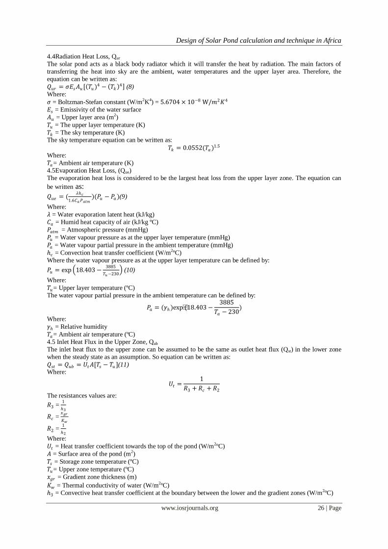
4.4Radiation Heat Loss, Qur
The solar pond acts as a black body radiator which it will transfer the heat by radiation. The main factors of
transferring the heat into sky are the ambient, water temperatures and the upper layer area. Therefore, the
equation can be written as:
𝑄𝑢𝑟 = 𝜎𝐸𝑠𝐴𝑢[ 𝑇𝑢)4 − 𝑇𝑘 4 (8)
Where:
𝜎 = Boltzman-Stefan constant (W/m2K4) = 5.6704 × 10⁻⁸ W/𝑚2𝐾4
𝐸𝑠 = Emissivity of the water surface
𝐴𝑢 = Upper layer area (m2)
𝑇𝑢 = The upper layer temperature (K)
𝑇𝑘 = The sky temperature (K) The sky temperature equation can be written as:
𝑇𝑘 = 0.0552(𝑇𝑎)1.5
Where:
𝑇𝑎= Ambient air temperature (K)
4.5Evaporation Heat Loss, (Que)
The evaporation heat loss is considered to be the largest heat loss from the upper layer zone. The equation can
be written as:
𝑄𝑢𝑒 = (𝜆ℎ𝑐
1.6𝐶𝑎𝑃𝑎𝑡𝑚)(𝑃𝑢 − 𝑃𝑎)(9)
Where:
𝜆 = Water evaporation latent heat (kJ/kg)
𝐶𝑎 = Humid heat capacity of air (kJ/kg ºC)
𝑃𝑎𝑡𝑚 = Atmospheric pressure (mmHg)
𝑃𝑢 = Water vapour pressure as at the upper layer temperature (mmHg)
𝑃𝑎 = Water vapour partial pressure in the ambient temperature (mmHg)
ℎ𝑐 = Convection heat transfer coefficient (W/m2ºC)
Where the water vapour pressure as at the upper layer temperature can be defined by:
𝑃𝑢 = exp 18.403 −3885
𝑇𝑢−230 (10)
Where:
𝑇𝑢= Upper layer temperature (ºC)
The water vapour partial pressure in the ambient temperature can be defined by:
𝑃𝑎 = (𝛾ℎ)exp(18.403 −3885
𝑇𝑎 − 230)
Where:
𝛾ℎ = Relative humidity
𝑇𝑎= Ambient air temperature (ºC) 4.5 Inlet Heat Flux in the Upper Zone, Qub
The inlet heat flux to the upper zone can be assumed to be the same as outlet heat flux (Qst) in the lower zone
when the steady state as an assumption. So equation can be written as:
𝑄𝑠𝑡 = 𝑄𝑢𝑏 = 𝑈𝑡𝐴[𝑇𝑠 − 𝑇𝑢 ](11) Where:
𝑈𝑡 =1
𝑅3 + 𝑅𝑐 + 𝑅2
The resistances values are:
𝑅3 = 1
ℎ3
𝑅𝑐 = 𝑥𝑔𝑟
𝐾𝑤
𝑅2 = 1
ℎ2
Where:
𝑈𝑡 = Heat transfer coefficient towards the top of the pond (W/m2ºC)
𝐴 = Surface area of the pond (m2)
𝑇𝑠 = Storage zone temperature (ºC)
𝑇𝑢= Upper zone temperature (ºC)
𝑥𝑔𝑟 = Gradient zone thickness (m)
𝐾𝑤 = Thermal conductivity of water (W/m2ºC)
ℎ3 = Convective heat transfer coefficient at the boundary between the lower and the gradient zones (W/m2ºC)

Design of Solar Pond calculation and technique in Africa
www.iosrjournals.org 27 | Page
ℎ2 = Convective heat transfer coefficient at the boundary between the upper and the gradient zones (W/m2ºC)
4.6 Heat loss from the sides The heat loss from the sides can be neglected, especially for large ponds. Also the good insulation materials will
be installed. Therefore:
𝑄𝑢𝑤 = 0(12)
V. The Steady State Model for Storage Zone The heat losses in the storage zone are less and can be more controlled that the upper zone as all type of
heat losses show in Figure 3. The heat losses that occur in the storage zone are mainly from conduction heat transfer. The appropriate insulation can be used for sides and bottom of the storage zone to improve the
performance of the storage zone. Also the gradient zone can affect the performance by obstructing the upward
heat loss from the storage zone to the upper zone. The steady state of model of storage zone can be written as:
𝜌𝑠𝐶𝑝𝑠𝐴𝑥𝑠𝑑𝑇
𝑑𝑡= 𝑄𝑠𝑟𝑠 − 𝑄𝑠𝑡 − 𝑄𝑠𝑏 −𝑄𝑠𝑤 −𝑄𝑠𝑒 (13)
Where:
𝜌𝑠= Density of Water
𝐶𝑝𝑠= Specific heat of water
𝐴 = Surface Area of the Pond
𝑥𝑠 = Thickness of the layer
𝑄𝑠𝑟𝑠 = Absorbed heat of solar radiation in the storage zone (W/m2)
𝑄𝑠𝑡 = Heat loss from the top in the storage zone (W/m2)
𝑄𝑠𝑏 = Heat loss from the bottom in the storage zone (W/m2)
𝑄𝑠𝑤 = Heat loss from the side in the storage zone (W/m2)
𝑄𝑠𝑒 = Heat loss by heat extraction in the storage zone (W/m2)
Fig.3.Theheat balance in the storage zone[4].
5.1Absorbed heat of solar radiation in the storage zone
The amount of absorbed solar radiation in the upper zone of a pond can be estimated according to the
amount of the solar beam attenuation at depth x of the storage zone. The equation would be the same as the
absorbed heat of solar radiation in the upper zone as mentioned earlier.
5.2 Sides and Heat Extraction Losses, Qsw and Qse
The storage zone causes the major heat losses through the sides of this zone. The amount of heat losses is mainly depending on the solar pond area. Therefore, the sides of this solar pond has decided to be insulated
which these heat losses can be neglected. So it is assumed that solar pond is in warming-up status, therefore, the
heat extraction assumed to be zero. Thus:
𝑄𝑠𝑤 = 0
𝑄𝑠𝑒 = 0 9(14)
5.3 Bottom Losses, Qsb
The heat losses at the bottom are also the major heat losses in this zone. It is also depended on the solar pond
area which large solar pond is likely to lose more heat than the small solar pond. The distance between the
bottom of solar pond and underground water table could affect the heat loss from the bottom, as more heat

Design of Solar Pond calculation and technique in Africa
www.iosrjournals.org 28 | Page
exchange occurs when the distance between underground water table and the storage zone is short. So the
equation of heat loss from the bottom can be written as:
𝑄𝑠𝑏 = 𝑈𝑏𝐴[𝑇𝑠 − 𝑇𝑔](15)
Where:
𝑈𝑏 =1
𝑅4 + 𝑅𝑔 + 𝑅5
The resistances values are:
𝑅4 = 1
ℎ4
𝑅𝑔 = 𝑥𝑔
𝐾𝑔
𝑅5 = 1
ℎ5
Where:
𝑈𝑔 = Heat transfer coefficient towards the top of the pond (W/m2ºC)
𝐴 = Surface area of the pond (m2)
𝑇𝑠 = Storage zone temperature (ºC)
𝑇𝑔= Ground sinks temperature (ºC)
𝑥𝑔 = The depth of ground sink zone (m)
𝐾𝑔 = Thermal conductivity of water (W/m2ºC)
ℎ4 = Convective heat transfer coefficient at the boundary between the storage zone and the surface of the bottom
(W/m2ºC)
ℎ5 = Convective heat transfer coefficient at the surface of the ground water sink (W/m2ºC)
5.4 Outlet Heat Flux in the Storage Zone, Qst As mentioned early, in the steady state assumption. The outlet heat flux would be equalled to the inlet heat flux,
therefore:
𝑄𝑠𝑡 = 𝑄𝑢𝑏 = 𝑈𝑡𝐴[𝑇𝑠 − 𝑇𝑢 ](16)
5.5 The Steady State Model for Gradient Zone
In steady state the gradient zone is being considered to maintain the temperature in the non convecting layer and
it can be considered a slab between the upper and the lower layer as the input heat and the output heat of this
Zone are equal.
The equations from previous chapter are for determining the storage zone temperature during different
months of a year. Due to computational complexities, time constraints and limited literature availability for solar
ponds, the existing solar pond in Riyadh, Saudi Arabia has been chosen for comparing the solar radiation due to
this region has similarity of the values ofparameters toCairo, Egypt which is shown in “Table‟‟ 2 from NASA
website and the irradiation plot in “Fig.” 4.
Design of Solar Pond calculation and technique in Africa
www.iosrjournals.org 29 | Page
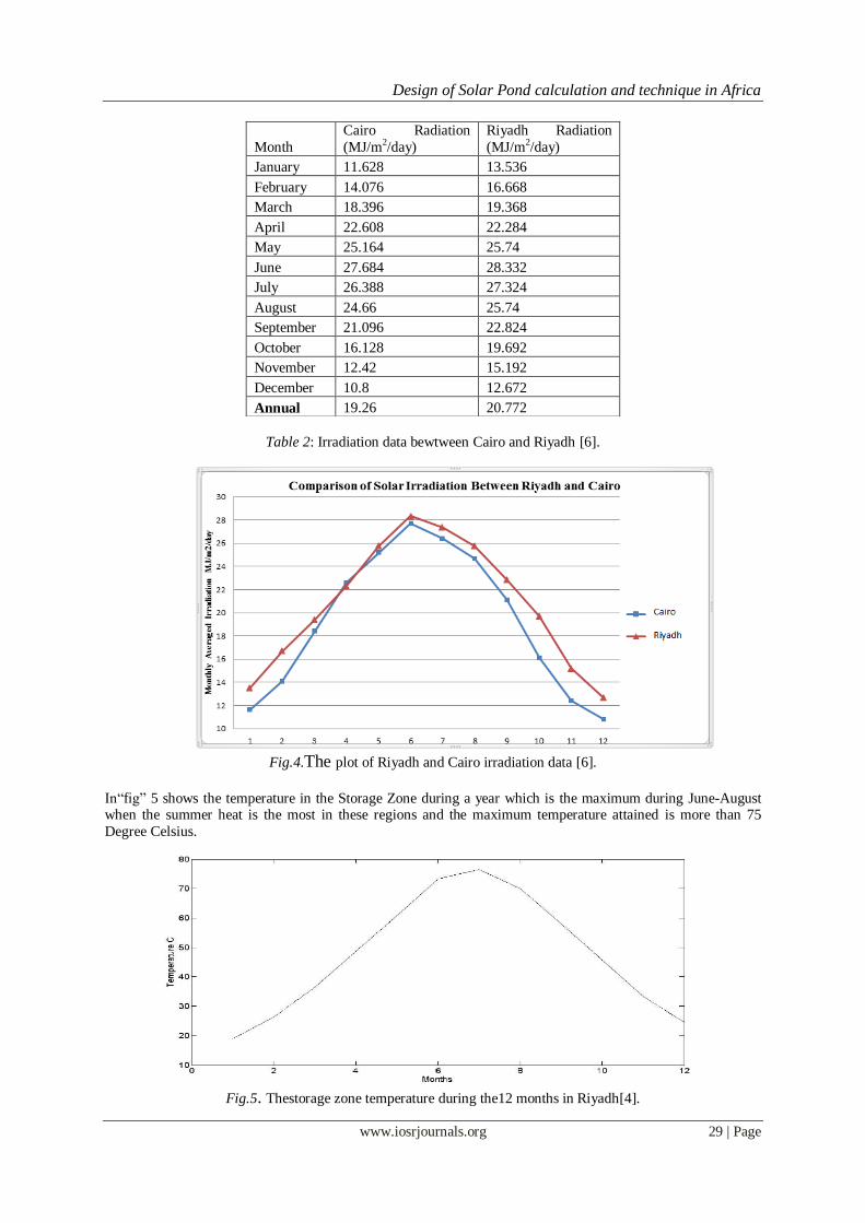
Table 2: Irradiation data bewtween Cairo and Riyadh [6].
Fig.4.The plot of Riyadh and Cairo irradiation data [6].
In“fig” 5 shows the temperature in the Storage Zone during a year which is the maximum during June-August when the summer heat is the most in these regions and the maximum temperature attained is more than 75
Degree Celsius.
Fig.5. Thestorage zone temperature during the12 months in Riyadh[4].
Month
Cairo Radiation
(MJ/m2/day)
Riyadh Radiation
(MJ/m2/day)
January 11.628 13.536
February 14.076 16.668
March 18.396 19.368
April 22.608 22.284
May 25.164 25.74
June 27.684 28.332
July 26.388 27.324
August 24.66 25.74
September 21.096 22.824
October 16.128 19.692
November 12.42 15.192
December 10.8 12.672
Annual 19.26 20.772
Design of Solar Pond calculation and technique in Africa
www.iosrjournals.org 30 | Page
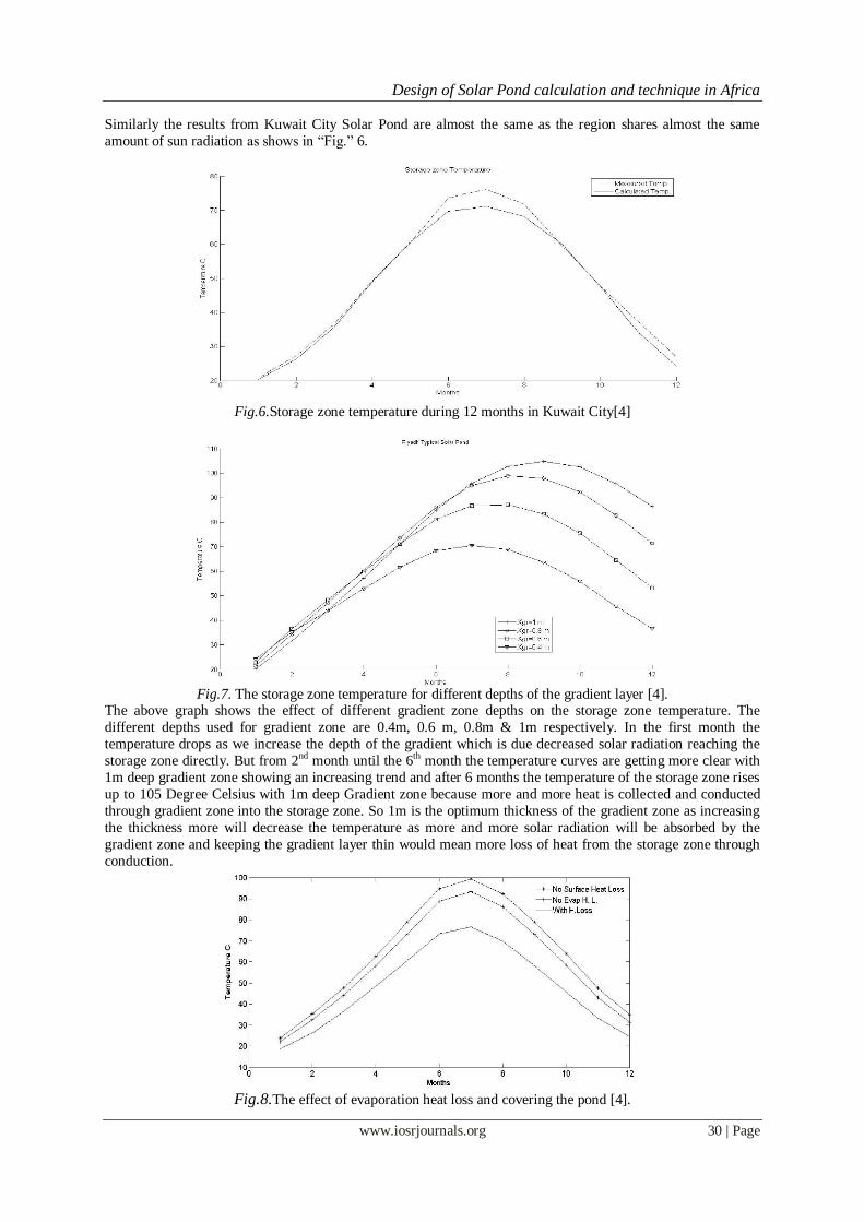
Similarly the results from Kuwait City Solar Pond are almost the same as the region shares almost the same
amount of sun radiation as shows in “Fig.” 6.
Fig.6.Storage zone temperature during 12 months in Kuwait City[4]
Fig.7. The storage zone temperature for different depths of the gradient layer [4].
The above graph shows the effect of different gradient zone depths on the storage zone temperature. The
different depths used for gradient zone are 0.4m, 0.6 m, 0.8m & 1m respectively. In the first month the
temperature drops as we increase the depth of the gradient which is due decreased solar radiation reaching the
storage zone directly. But from 2nd month until the 6th month the temperature curves are getting more clear with
1m deep gradient zone showing an increasing trend and after 6 months the temperature of the storage zone rises
up to 105 Degree Celsius with 1m deep Gradient zone because more and more heat is collected and conducted
through gradient zone into the storage zone. So 1m is the optimum thickness of the gradient zone as increasing
the thickness more will decrease the temperature as more and more solar radiation will be absorbed by the
gradient zone and keeping the gradient layer thin would mean more loss of heat from the storage zone through
conduction.
Fig.8.The effect of evaporation heat loss and covering the pond [4].
Design of Solar Pond calculation and technique in Africa
www.iosrjournals.org 31 | Page
Temperature has an interesting effect on the storage zone temperature of the solar pond. The temperature of the
storage zone should increase with the increase in the surrounding temperature but losses due to evaporation,
radiation, conduction and convection decreases the storage zone temperature. Solar pond has a heat loss due to evaporation in increasing temperatures which can be reduced by covering the solar pond. The above graph
clearly shows an increase in the storage zone temperature after covering the solar pond.
Increasing the thickness of the top insulation increases the storage zone temperature. It can be analyzed
from the graph that the heat loss reduces a lot by increasing the thickness upto 40 cm. Some studies suggest that
the heat losses are reduced by 55% with 10 cm thickness of insulation and the thickness from 20-40 cm reduces
the heat losses further upto 6% and the stored energy is increased by 15%. Further increasing the thickness of
insulation has no effect on the heat loss and the stored energy.
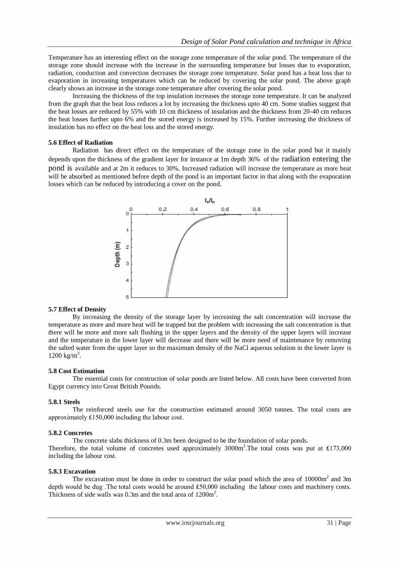
5.6 Effect of Radiation
Radiation has direct effect on the temperature of the storage zone in the solar pond but it mainly
depends upon the thickness of the gradient layer for instance at 1m depth 36% of the radiation entering the
pond is available and at 2m it reduces to 30%. Increased radiation will increase the temperature as more heat
will be absorbed as mentioned before depth of the pond is an important factor in that along with the evaporation losses which can be reduced by introducing a cover on the pond.
5.7 Effect of Density
By increasing the density of the storage layer by increasing the salt concentration will increase the
temperature as more and more heat will be trapped but the problem with increasing the salt concentration is that
there will be more and more salt flushing in the upper layers and the density of the upper layers will increase
and the temperature in the lower layer will decrease and there will be more need of maintenance by removing
the salted water from the upper layer so the maximum density of the NaCl aqueous solution in the lower layer is
1200 kg/m3.
5.8 Cost Estimation
The essential costs for construction of solar ponds are listed below. All costs have been converted from
Egypt currency into Great British Pounds.
5.8.1 Steels
The reinforced steels use for the construction estimated around 3050 tonnes. The total costs are
approximately ₤150,000 including the labour cost.
5.8.2 Concretes
The concrete slabs thickness of 0.3m been designed to be the foundation of solar ponds.
Therefore, the total volume of concretes used approximately 3000m3.The total costs was put at ₤173,000 including the labour cost.
5.8.3 Excavation
The excavation must be done in order to construct the solar pond which the area of 10000m2 and 3m
depth would be dug .The total costs would be around ₤50,000 including the labour costs and machinery costs.
Thickness of side walls was 0.3m and the total area of 1200m2.
Design of Solar Pond calculation and technique in Africa
www.iosrjournals.org 32 | Page
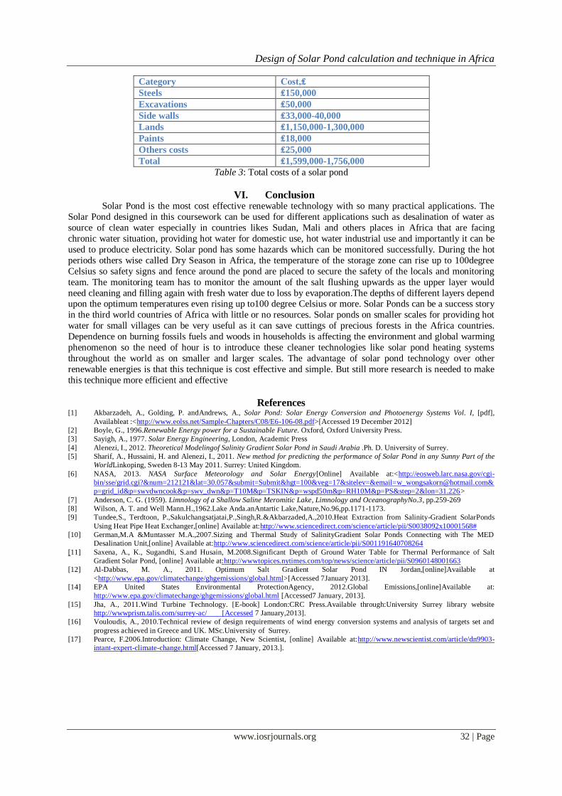
Category Cost,₤
Steels ₤150,000
Excavations ₤50,000
Side walls ₤33,000-40,000
Lands ₤1,150,000-1,300,000
Paints ₤18,000
Others costs ₤25,000
Total ₤1,599,000-1,756,000
Table 3: Total costs of a solar pond
VI. Conclusion Solar Pond is the most cost effective renewable technology with so many practical applications. The
Solar Pond designed in this coursework can be used for different applications such as desalination of water as
source of clean water especially in countries likes Sudan, Mali and others places in Africa that are facing
chronic water situation, providing hot water for domestic use, hot water industrial use and importantly it can be
used to produce electricity. Solar pond has some hazards which can be monitored successfully. During the hot
periods others wise called Dry Season in Africa, the temperature of the storage zone can rise up to 100degree
Celsius so safety signs and fence around the pond are placed to secure the safety of the locals and monitoring
team. The monitoring team has to monitor the amount of the salt flushing upwards as the upper layer would
need cleaning and filling again with fresh water due to loss by evaporation.The depths of different layers depend upon the optimum temperatures even rising up to100 degree Celsius or more. Solar Ponds can be a success story
in the third world countries of Africa with little or no resources. Solar ponds on smaller scales for providing hot
water for small villages can be very useful as it can save cuttings of precious forests in the Africa countries.
Dependence on burning fossils fuels and woods in households is affecting the environment and global warming
phenomenon so the need of hour is to introduce these cleaner technologies like solar pond heating systems
throughout the world as on smaller and larger scales. The advantage of solar pond technology over other
renewable energies is that this technique is cost effective and simple. But still more research is needed to make
this technique more efficient and effective
References [1] Akbarzadeh, A., Golding, P. andAndrews, A., Solar Pond: Solar Energy Conversion and Photoenergy Systems Vol. I, [pdf],
Availableat :<http://www.eolss.net/Sample-Chapters/C08/E6-106-08.pdf>[Accessed 19 December 2012]
[2] Boyle, G., 1996.Renewable Energy power for a Sustainable Future. Oxford, Oxford University Press.
[3] Sayigh, A., 1977. Solar Energy Engineering, London, Academic Press
[4] Alenezi, I., 2012. Theoretical Modelingof Salinity Gradient Solar Pond in Saudi Arabia .Ph. D. University of Surrey.
[5] Sharif, A., Hussaini, H. and Alenezi, I., 2011. New method for predicting the performance of Solar Pond in any Sunny Part of the
WorldLinkoping, Sweden 8-13 May 2011. Surrey: United Kingdom.
[6] NASA, 2013. NASA Surface Meteorology and Solar Energy[Online] Available at:<http://eosweb.larc.nasa.gov/cgi-
bin/sse/grid.cgi?&num=212121&lat=30.057&submit=Submit&hgt=100&veg=17&sitelev=&[email protected]&
p=grid_id&p=swvdwncook&p=swv_dwn&p=T10M&p=TSKIN&p=wspd50m&p=RH10M&p=PS&step=2&lon=31.226>
[7] Anderson, C. G. (1959). Limnology of a Shallow Saline Meromitic Lake, Limnology and OceanographyNo.3, pp.259-269
[8] Wilson, A. T. and Well Mann.H.,1962.Lake Anda.anAntartic Lake,Nature,No.96,pp.1171-1173.
[9] Tundee,S., Terdtoon, P.,Sakulchangsatjatai,P.,Singh,R.&Akbarzaded,A.,2010.Heat Extraction from Salinity-Gradient SolarPonds
Using Heat Pipe Heat Exchanger,[online] Available at:http://www.sciencedirect.com/science/article/pii/S0038092x10001568#
[10] German,M.A &Muntasser M.A.,2007.Sizing and Thermal Study of SalinityGradient Solar Ponds Connecting with The MED
Desalination Unit,[online] Available at:http://www.sciencedirect.com/science/article/pii/S001191640708264
[11] Saxena, A., K., Sugandhi, S.and Husain, M.2008.Significant Depth of Ground Water Table for Thermal Performance of Salt
Gradient Solar Pond, [online] Available at:http://wwwtopices.nytimes.com/top/news/science/article/pii/S0960148001663
[12] Al-Dabbas, M. A., 2011. Optimum Salt Gradient Solar Pond IN Jordan,[online]Available at
<http://www.epa.gov/climatechange/ghgemissions/global.html>[Accessed 7January 2013].
[14] EPA United States Environmental ProtectionAgency, 2012.Global Emissions,[online]Available at:
http://www.epa.gov/climatechange/ghgemissions/global.html [Accessed7 January, 2013].
[15] Jha, A., 2011.Wind Turbine Technology. [E-book] London:CRC Press.Available through:University Surrey library website
http://wwwprism.talis.com/surrey-ac/ [Accessed 7 January,2013].
[16] Vouloudis, A., 2010.Technical review of design requirements of wind energy conversion systems and analysis of targets set and
progress achieved in Greece and UK. MSc.University of Surrey.
[17] Pearce, F.2006.Introduction: Climate Change, New Scientist, [online] Available at:http://www.newscientist.com/article/dn9903-
intant-expert-climate-change.html[Accessed 7 January, 2013.].