
DESIGN OF SOLAR BAG USING DC-DC BOOST CONVERTER
10
DESIGN OF SOLAR BAG USING DC-DC BOOST CONVERTER K.Deepikavalli, R.Puviarasi Saveetha School of Engineering, Thandalam, Chennai Saveetha Institute of Medical and Technical Sciences Abstract The backpack would store vitality from sun oriented cells put on its outside, which could then be utilized to charge individuals' electronic gadgets, for example, a mobile phone or iPod. Charging your contraptions every so often on account of depleted battery particularly when you are not at home or office is an issue looked by every one of us. To tackle this issue, Charge your contraptions by making your own particular sunlight based battery charger, at that point join it to your most loved tote or rucksack. Front piece of sack is secured with sunlight based board, which will constantly create control through light while we travel. Inside structure comprise of rechargeable battery for a use like charging cell phone or tab, tablet. You can all the while charge your battery under the sun and with no weight of depleting battery. Keywords:- Solar Panel, Boost converter, Battery 1 Introduction The particular transport of electrons and openings to the two terminals of a daylight based cell is consistently credited to an electric field, though doubtlessly comprehended material science communicates that they are driven by edges of semi Fermi energies [1]. Regardless, in a lit up semiconductor, these forces are not specific, and they drive both charge transporters toward the two contacts [2]. This paper shows that the principal selectivity is refined by contrasts in the conductivities of electrons what’s more, holes in two unmistakable areas of the device, which, for one charge transporter, empowers transport to one contact and piece transport to the following contact. The investigation of photovoltaic properties in perovskite sun oriented cells to investigate the effect of excitonic highlights, issue, recombination, and space charge impacts utilizing temperature and photograph power reliance [3]. Photograph force reliance uncovers an upgrade of established Einstein connection because of the nearness of traps and arrangement of room charge impacts bringing about decreased conductivity [4]. Exciton versus free charge thickness upon photograph excitation is broke down from temperature reliance of photocurrent. We built up an enhanced model to fit the photocurrent thickness versus voltage in natural sun based cells [5]. Our model quantitatively represents the band twisting close to the cathodes caused by charge aggregation in the dynamic layer [6]. The model clarifies the position of the implicit and the zero-field voltage, the estimation of the interior electric field, the effect of cathode materials, and the presence of various articulations. We think about the demonstrating and (powerful) control of a DC- DC Boost converter. Specifically, we determine a scientific model comprising of a International Journal of Pure and Applied Mathematics Volume 119 No. 15 2018, 2567-2575 ISSN: 1314-3395 (on-line version) url: http://www.acadpubl.eu/hub/ Special Issue http://www.acadpubl.eu/hub/ 2567
-
Upload
khangminh22 -
Category
Documents
-
view
3 -
download
0
Transcript of DESIGN OF SOLAR BAG USING DC-DC BOOST CONVERTER
DESIGN OF SOLAR BAG USING DC-DC BOOST
CONVERTER
K.Deepikavalli, R.Puviarasi
Saveetha School of Engineering, Thandalam, Chennai
Saveetha Institute of Medical and Technical Sciences
Abstract
The backpack would store vitality from sun
oriented cells put on its outside, which could
then be utilized to charge individuals'
electronic gadgets, for example, a mobile
phone or iPod. Charging your contraptions
every so often on account of depleted battery
particularly when you are not at home or
office is an issue looked by every one of us. To
tackle this issue, Charge your contraptions by
making your own particular sunlight based
battery charger, at that point join it to your
most loved tote or rucksack. Front piece of
sack is secured with sunlight based board,
which will constantly create control through
light while we travel. Inside structure
comprise of rechargeable battery for a use like
charging cell phone or tab, tablet. You can all
the while charge your battery under the sun
and with no weight of depleting battery.
Keywords:- Solar Panel, Boost converter,
Battery
1 Introduction
The particular transport of electrons and
openings to the two terminals of a daylight
based cell is consistently credited to an
electric field, though doubtlessly
comprehended material science communicates
that they are driven by edges of semi Fermi
energies [1]. Regardless, in a lit up
semiconductor, these forces are not specific,
and they drive both charge transporters
toward the two contacts [2]. This paper shows
that the principal selectivity is refined by
contrasts in the conductivities of electrons
what’s more, holes in two unmistakable areas
of the device, which, for one charge
transporter, empowers transport to one
contact and piece transport to the following
contact.
The investigation of photovoltaic properties in
perovskite sun oriented cells to investigate the
effect of excitonic highlights, issue,
recombination, and space charge impacts
utilizing temperature and photograph power
reliance [3]. Photograph force reliance
uncovers an upgrade of established Einstein
connection because of the nearness of traps
and arrangement of room charge impacts
bringing about decreased conductivity [4].
Exciton versus free charge thickness upon
photograph excitation is broke down from
temperature reliance of photocurrent.
We built up an enhanced model to fit the
photocurrent thickness versus voltage in
natural sun based cells [5]. Our model
quantitatively represents the band twisting
close to the cathodes caused by charge
aggregation in the dynamic layer [6]. The
model clarifies the position of the implicit and
the zero-field voltage, the estimation of the
interior electric field, the effect of cathode
materials, and the presence of various
articulations. We think about the
demonstrating and (powerful) control of a DC-
DC Boost converter. Specifically, we
determine a scientific model comprising of a
International Journal of Pure and Applied MathematicsVolume 119 No. 15 2018, 2567-2575ISSN: 1314-3395 (on-line version)url: http://www.acadpubl.eu/hub/Special Issue http://www.acadpubl.eu/hub/
2567
compelled exchanged differential
consideration that incorporates every single
conceivable method of operation of the
converter [7]. The ensured vigor properties
guarantee appropriate operation of the
converter within the sight of clamor in the
state; undemonstrated flow, and spatial
regularization to decrease the high rate of
exchanging [8]. The foundation of these
properties is empowered by late devices for
the investigation of vigorous security in half
and half frameworks [9].
An information parallel, yield arrangement
dc-dc Boost converter with a wide info voltage
run is proposed in this paper [10]. An
interleaved structure is received in the info
side of this converter to diminish input
current swell [11]. Two capacitors are
associated in arrangement on the yield side to
accomplish a high voltage pick up.
Two sorts of semi conductive antimony tin
oxide (ATO) covering (single and numerous
layers) have been connected on sun based cells
and a charge collection test has been
performed under high-vitality electron bars
reenacting a geostationary earth circle
condition and ECR plasma reproducing a low
earth circle condition [12]. No charge has been
amassed on the covered sun oriented cells
though a high energize has based on the non
covered sunlight based cells, affirmed by a non
reaching surface potential test [13].
Electrostatic release (ESD) testing has
additionally been performed on both the
covered and non covered sun powered cells; be
that as it may, no ESD has been recognized on
the covered sunlight based cells [14]. Hence,
ATO covering on sun oriented cells can be
utilized for charging moderation.
On the plan and development of a
streamlining charging framework for Li-Po
batteries by methods for followed sunlight
based boards. Accordingly, the usage of a total
vitality administration framework connected
to an automated investigation vehicle is
advanced [15]. The enthusiasm of this
mechanical framework lies in the outline idea,
in light of a keen host microcontroller.
Aggregators charged by methods for Solar cell
exhibits are presented to cheat issues due to
the uncontrolled wellspring of the vitality, the
Sun. These issues are portrayed and talked
about and a few arrangements are illustrated
[16]. A straightforward and rather valuable
arrangement, for the previously mentioned
issue, is given for certain earthbound
frameworks. This charging control framework
is portrayed in points of interest as it is
connected to operational frameworks in which
gatherers assume an essential part as electric
vitality sources[17].
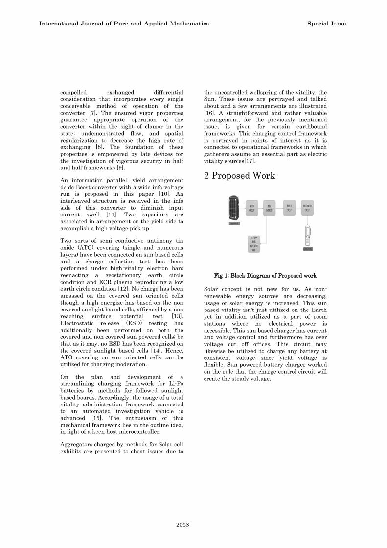
2 Proposed Work
Fig 1: Block Diagram of Proposed work
Solar concept is not new for us. As non-
renewable energy sources are decreasing,
usage of solar energy is increased. This sun
based vitality isn't just utilized on the Earth
yet in addition utilized as a part of room
stations where no electrical power is
accessible. This sun based charger has current
and voltage control and furthermore has over
voltage cut off offices. This circuit may
likewise be utilized to charge any battery at
consistent voltage since yield voltage is
flexible. Sun powered battery charger worked
on the rule that the charge control circuit will
create the steady voltage.
International Journal of Pure and Applied Mathematics Special Issue
2568
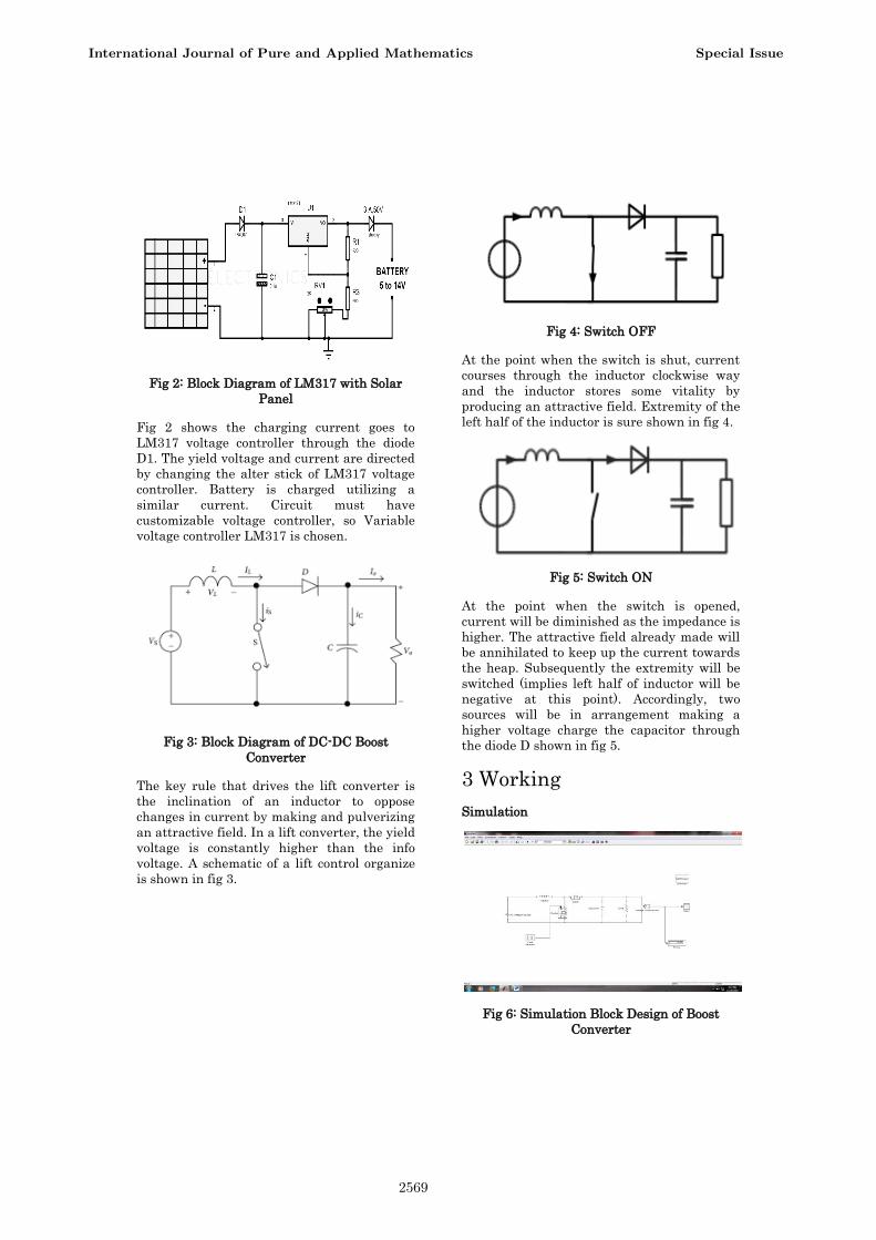
Fig 2: Block Diagram of LM317 with Solar
Panel
Fig 2 shows the charging current goes to
LM317 voltage controller through the diode
D1. The yield voltage and current are directed
by changing the alter stick of LM317 voltage
controller. Battery is charged utilizing a
similar current. Circuit must have
customizable voltage controller, so Variable
voltage controller LM317 is chosen.
Fig 3: Block Diagram of DC-DC Boost
Converter
The key rule that drives the lift converter is
the inclination of an inductor to oppose
changes in current by making and pulverizing
an attractive field. In a lift converter, the yield
voltage is constantly higher than the info
voltage. A schematic of a lift control organize
is shown in fig 3.
Fig 4: Switch OFF
At the point when the switch is shut, current
courses through the inductor clockwise way
and the inductor stores some vitality by
producing an attractive field. Extremity of the
left half of the inductor is sure shown in fig 4.
Fig 5: Switch ON
At the point when the switch is opened,
current will be diminished as the impedance is
higher. The attractive field already made will
be annihilated to keep up the current towards
the heap. Subsequently the extremity will be
switched (implies left half of inductor will be
negative at this point). Accordingly, two
sources will be in arrangement making a
higher voltage charge the capacitor through
the diode D shown in fig 5.
3 Working
Simulation
Fig 6: Simulation Block Design of Boost
Converter
International Journal of Pure and Applied Mathematics Special Issue
2569
The DC contribution to a lift converter can be
from numerous sources and also batteries, for
example, amended AC from the mains supply,
or DC from sun oriented boards, energy
components, dynamos and DC generators. The
lift converter is distinctive to the Buck
Converter in that it's yield voltage is
equivalent to, or more prominent than its
information voltage. Be that as it may it is
essential to recall that, as power (P) = voltage
(V) x current (I), if the yield voltage is
expanded, the accessible yield current must
lessening. The fundamental circuit of a Boost
converter. Be that as it may, in this case the
exchanging transistor is a power MOSFET,
both Bipolar power transistors and MOSFETs
are utilized as a part of energy exchanging,
the decision being dictated by the present,
voltage, exchanging rate and cost
contemplations.
Fig 7: Simulation of PV based Dc-Dc Boost
converter
Hardware
These batteries can give several amps of
electrical current for a brief timeframe. This is
the reason these batteries are ordinarily
utilized as a part of car applications.
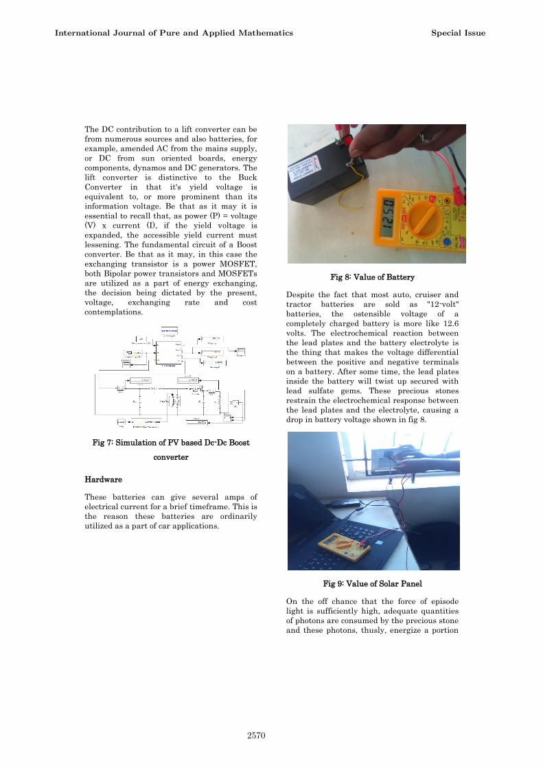
Fig 8: Value of Battery
Despite the fact that most auto, cruiser and
tractor batteries are sold as "12-volt"
batteries, the ostensible voltage of a
completely charged battery is more like 12.6
volts. The electrochemical reaction between
the lead plates and the battery electrolyte is
the thing that makes the voltage differential
between the positive and negative terminals
on a battery. After some time, the lead plates
inside the battery will twist up secured with
lead sulfate gems. These precious stones
restrain the electrochemical response between
the lead plates and the electrolyte, causing a
drop in battery voltage shown in fig 8.
Fig 9: Value of Solar Panel
On the off chance that the force of episode
light is sufficiently high, adequate quantities
of photons are consumed by the precious stone
and these photons, thusly, energize a portion
International Journal of Pure and Applied Mathematics Special Issue
2570
of the electrons of covalent bonds. These
energized electrons at that point get adequate
vitality to relocate from valence band to
conduction band. As the vitality level of these
electrons is in the conduction band, they leave
from the covalent bond leaving a gap in the
bond behind each expelled electron. These
electrons and openings are consequently
called light-produced electrons and gaps
individually. These light created electrons and
gaps can't deliver power in the silicon precious
stone alone shown in fig 9.
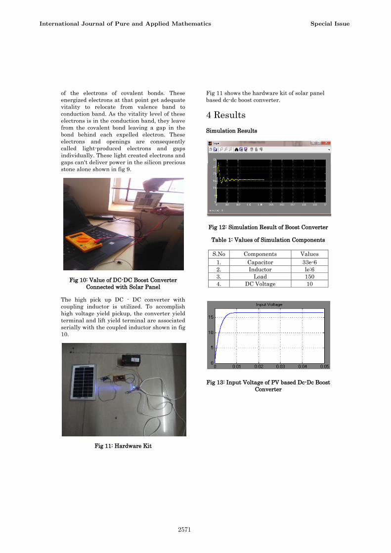
Fig 10: Value of DC-DC Boost Converter
Connected with Solar Panel
The high pick up DC - DC converter with
coupling inductor is utilized. To accomplish
high voltage yield pickup, the converter yield
terminal and lift yield terminal are associated
serially with the coupled inductor shown in fig
10.
Fig 11: Hardware Kit
Fig 11 shows the hardware kit of solar panel
based dc-dc boost converter.
4 Results
Simulation Results
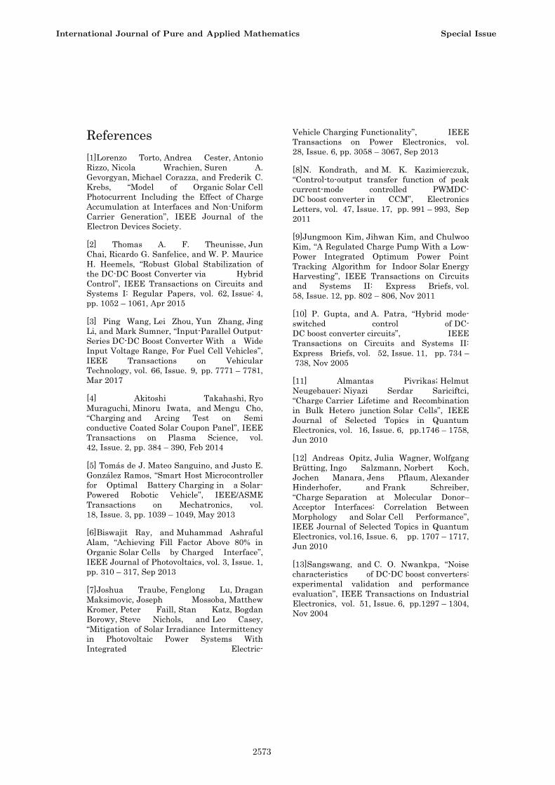
Fig 12: Simulation Result of Boost Converter
Table 1: Values of Simulation Components
S.No Components Values
1. Capacitor 33e-6
2. Inductor le:6
3. Load 150
4. DC Voltage 10
Fig 13: Input Voltage of PV based Dc-Dc Boost
Converter
International Journal of Pure and Applied Mathematics Special Issue
2571
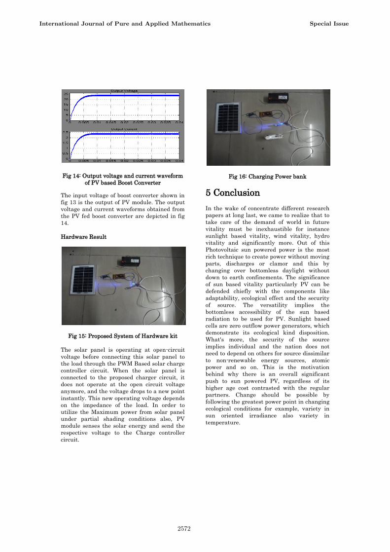
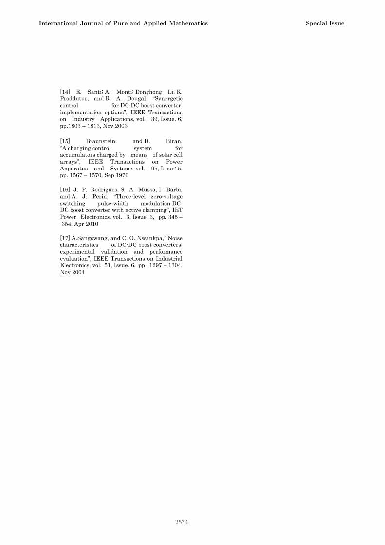
Fig 14: Output voltage and current waveform
of PV based Boost Converter
The input voltage of boost converter shown in
fig 13 is the output of PV module. The output
voltage and current waveforms obtained from
the PV fed boost converter are depicted in fig
14.
Hardware Result
Fig 15: Proposed System of Hardware kit
The solar panel is operating at open-circuit
voltage before connecting this solar panel to
the load through the PWM Based solar charge
controller circuit. When the solar panel is
connected to the proposed charger circuit, it
does not operate at the open circuit voltage
anymore, and the voltage drops to a new point
instantly. This new operating voltage depends
on the impedance of the load. In order to
utilize the Maximum power from solar panel
under partial shading conditions also, PV
module senses the solar energy and send the
respective voltage to the Charge controller
circuit.
Fig 16: Charging Power bank
5 Conclusion
In the wake of concentrate different research
papers at long last, we came to realize that to
take care of the demand of world in future
vitality must be inexhaustible for instance
sunlight based vitality, wind vitality, hydro
vitality and significantly more. Out of this
Photovoltaic sun powered power is the most
rich technique to create power without moving
parts, discharges or clamor and this by
changing over bottomless daylight without
down to earth confinements. The significance
of sun based vitality particularly PV can be
defended chiefly with the components like
adaptability, ecological effect and the security
of source. The versatility implies the
bottomless accessibility of the sun based
radiation to be used for PV. Sunlight based
cells are zero outflow power generators, which
demonstrate its ecological kind disposition.
What's more, the security of the source
implies individual and the nation does not
need to depend on others for source dissimilar
to non-renewable energy sources, atomic
power and so on. This is the motivation
behind why there is an overall significant
push to sun powered PV, regardless of its
higher age cost contrasted with the regular
partners. Change should be possible by
following the greatest power point in changing
ecological conditions for example, variety in
sun oriented irradiance also variety in
temperature.
International Journal of Pure and Applied Mathematics Special Issue
2572
References
[1]Lorenzo Torto, Andrea Cester, Antonio
Rizzo, Nicola Wrachien, Suren A.
Gevorgyan, Michael Corazza, and Frederik C.
Krebs, “Model of Organic Solar Cell
Photocurrent Including the Effect of Charge
Accumulation at Interfaces and Non-Uniform
Carrier Generation”, IEEE Journal of the
Electron Devices Society.
[2] Thomas A. F. Theunisse, Jun
Chai, Ricardo G. Sanfelice, and W. P. Maurice
H. Heemels, “Robust Global Stabilization of
the DC-DC Boost Converter via Hybrid
Control”, IEEE Transactions on Circuits and
Systems I: Regular Papers, vol. 62, Issue: 4,
pp. 1052 – 1061, Apr 2015
[3] Ping Wang, Lei Zhou, Yun Zhang, Jing
Li, and Mark Sumner, “Input-Parallel Output-
Series DC-DC Boost Converter With a Wide
Input Voltage Range, For Fuel Cell Vehicles”,
IEEE Transactions on Vehicular
Technology, vol. 66, Issue. 9, pp. 7771 – 7781,
Mar 2017
[4] Akitoshi Takahashi, Ryo
Muraguchi, Minoru Iwata, and Mengu Cho,
“Charging and Arcing Test on Semi
conductive Coated Solar Coupon Panel”, IEEE
Transactions on Plasma Science, vol.
42, Issue. 2, pp. 384 – 390, Feb 2014
[5] Tomás de J. Mateo Sanguino, and Justo E.
González Ramos, “Smart Host Microcontroller
for Optimal Battery Charging in a Solar-
Powered Robotic Vehicle”, IEEE/ASME
Transactions on Mechatronics, vol.
18, Issue. 3, pp. 1039 – 1049, May 2013
[6]Biswajit Ray, and Muhammad Ashraful
Alam, “Achieving Fill Factor Above 80% in
Organic Solar Cells by Charged Interface”,
IEEE Journal of Photovoltaics, vol. 3, Issue. 1,
pp. 310 – 317, Sep 2013
[7]Joshua Traube, Fenglong Lu, Dragan
Maksimovic, Joseph Mossoba, Matthew
Kromer, Peter Faill, Stan Katz, Bogdan
Borowy, Steve Nichols, and Leo Casey,
“Mitigation of Solar Irradiance Intermittency
in Photovoltaic Power Systems With
Integrated Electric-
Vehicle Charging Functionality”, IEEE
Transactions on Power Electronics, vol.
28, Issue. 6, pp. 3058 – 3067, Sep 2013
[8]N. Kondrath, and M. K. Kazimierczuk,
“Control-to-output transfer function of peak
current-mode controlled PWMDC-
DC boost converter in CCM”, Electronics
Letters, vol. 47, Issue. 17, pp. 991 – 993, Sep
2011
[9]Jungmoon Kim, Jihwan Kim, and Chulwoo
Kim, “A Regulated Charge Pump With a Low-
Power Integrated Optimum Power Point
Tracking Algorithm for Indoor Solar Energy
Harvesting”, IEEE Transactions on Circuits
and Systems II: Express Briefs, vol.
58, Issue. 12, pp. 802 – 806, Nov 2011
[10] P. Gupta, and A. Patra, “Hybrid mode-
switched control of DC-
DC boost converter circuits”, IEEE
Transactions on Circuits and Systems II:
Express Briefs, vol. 52, Issue. 11, pp. 734 –
738, Nov 2005
[11] Almantas Pivrikas; Helmut
Neugebauer; Niyazi Serdar Sariciftci,
“Charge Carrier Lifetime and Recombination
in Bulk Hetero junction Solar Cells”, IEEE
Journal of Selected Topics in Quantum
Electronics, vol. 16, Issue. 6, pp.1746 – 1758,
Jun 2010
[12] Andreas Opitz, Julia Wagner, Wolfgang
Brütting, Ingo Salzmann, Norbert Koch,
Jochen Manara, Jens Pflaum, Alexander
Hinderhofer, and Frank Schreiber,
“Charge Separation at Molecular Donor–
Acceptor Interfaces: Correlation Between
Morphology and Solar Cell Performance”,
IEEE Journal of Selected Topics in Quantum
Electronics, vol.16, Issue. 6, pp. 1707 – 1717,
Jun 2010
[13]Sangswang, and C. O. Nwankpa, “Noise
characteristics of DC-DC boost converters:
experimental validation and performance
evaluation”, IEEE Transactions on Industrial
Electronics, vol. 51, Issue. 6, pp.1297 – 1304,
Nov 2004
International Journal of Pure and Applied Mathematics Special Issue
2573
[14] E. Santi; A. Monti; Donghong Li, K.
Proddutur, and R. A. Dougal, “Synergetic
control for DC-DC boost converter:
implementation options”, IEEE Transactions
on Industry Applications, vol. 39, Issue. 6,
pp.1803 – 1813, Nov 2003
[15] Braunstein, and D. Biran,
“A charging control system for
accumulators charged by means of solar cell
arrays”, IEEE Transactions on Power
Apparatus and Systems, vol. 95, Issue: 5,
pp. 1567 – 1570, Sep 1976
[16] J. P. Rodrigues, S. A. Mussa, I. Barbi,
and A. J. Perin, “Three-level zero-voltage
switching pulse-width modulation DC-
DC boost converter with active clamping”, IET
Power Electronics, vol. 3, Issue. 3, pp. 345 –
354, Apr 2010
[17] A.Sangswang, and C. O. Nwankpa, “Noise
characteristics of DC-DC boost converters:
experimental validation and performance
evaluation”, IEEE Transactions on Industrial
Electronics, vol. 51, Issue. 6, pp. 1297 – 1304,
Nov 2004
International Journal of Pure and Applied Mathematics Special Issue
2574

2575

2576