Design of Profile of the Non-Circular Gears
8
G-2008-A-08 1 Design of Profile of the Non-Circular Gears B.Laczik TUB Budapest, Hungary, [email protected] Abstracts: this paper presents an approach to derive profile of teeth of non-circular gears. The calculation based on the complex algebraic methods to the points of exact und undercut part of involute profile. The derivation and illustration of the article are made by the mathematical software Maple ® . Keywords: non-circular gear, involute profile, undercutting, Maple ® Introduction Non-circular gears are generally used to provide irregular motions. The common requirement for the usage of non-circular geared (or gear and rack) mechanisms is to transfer a stable input angular (or linear) velocity into various output angular (or linear) velocity. An earlier version of the non-circular gear is shown on a sketch made by Leonardo da Vinchi in the collection of “Codex Madridii”, see Fig. 1 a/. In the 17-18 th century more practical applications of non-circular gears in clockworks, astronomical devices, musical instruments and another mechanical toys was used. The first version of the so called cometarium mechanism demonstrated the II. Kepler’s law of astronomy by rolling elliptical centrodes ([1-3]). Other similar devices also used elliptical gears (see Fig. 1/b). a/ b/ Figure 1 There are some well-known non-circular gear models made by F.Reuleaux to study the kinematics in the technical education in the beginning of the 20 th century. In the middle of the 20th century the non- circular gearing was used in electromechanical systems to control and drive non-linear potentiometers. Non-circular gears (NCG’s) are long known elements of machinery but these days they are unworthy rarely applied mechanisms. For the realization of periodical altering (circular or/and linear) motion controlled positioning devices are widespread. The simplicity, the price, the mechanical power, the tolerance for overload and the duration of the NCG’s are in each case a competitive alternative of electrical servo drives. In spite of the improvement of digital techniques, the importance of non- circular gears has not decreased. In the huge lifework of Mr. F. L. Litvin study of the non-circular gearing play an important role. In an earlier book [4] all basic questions of these special machinery elements are discussed exhaustively. In the corresponding chapters of a new book [5] by Litvin the author summarises the most important theoretical results in [6]. Some practical questions are published by the author in studys [7-9] abouth design, manufacturing and measuring of NCGs. Some of the articles [10-16] reflect the issues of the new constructions and manufacturing techniques.
-
Upload
khangminh22 -
Category
Documents
-
view
5 -
download
0
Transcript of Design of Profile of the Non-Circular Gears
G-2008-A-08 1
Design of Profile of the Non-Circular Gears B.Laczik TUB Budapest, Hungary, [email protected]
Abstracts: this paper presents an approach to derive profile of teeth of non-circular gears. The calculation based on the complex algebraic methods to the points of exact und undercut part of involute profile. The derivation and
illustration of the article are made by the mathematical software Maple®.
Keywords: non-circular gear, involute profile, undercutting, Maple
®
Introduction Non-circular gears are generally used to provide irregular motions. The common requirement for the usage of non-circular geared (or gear and rack) mechanisms is to transfer a stable input angular (or linear) velocity into various output angular (or linear) velocity. An earlier version of the non-circular gear is shown on a sketch made by Leonardo da Vinchi in the collection of “Codex Madridii”, see Fig. 1 a/. In the 17-18th century more practical applications of non-circular gears in clockworks, astronomical devices, musical instruments and another mechanical toys was used. The first version of the so called cometarium mechanism demonstrated the II. Kepler’s law of astronomy by rolling elliptical centrodes ([1-3]). Other similar devices also used elliptical gears (see Fig. 1/b).
a/ b/
Figure 1
There are some well-known non-circular gear models made by F.Reuleaux to study the kinematics in the technical education in the beginning of the 20th century. In the middle of the 20th century the non-circular gearing was used in electromechanical systems to control and drive non-linear potentiometers. Non-circular gears (NCG’s) are long known elements of machinery but these days they are unworthy rarely applied mechanisms. For the realization of periodical altering (circular or/and linear) motion controlled positioning devices are widespread. The simplicity, the price, the mechanical power, the tolerance for overload and the duration of the NCG’s are in each case a competitive alternative of electrical servo drives. In spite of the improvement of digital techniques, the importance of non-circular gears has not decreased. In the huge lifework of Mr. F. L. Litvin study of the non-circular gearing play an important role. In an earlier book [4] all basic questions of these special machinery elements are discussed exhaustively. In the corresponding chapters of a new book [5] by Litvin the author summarises the most important theoretical results in [6]. Some practical questions are published by the author in studys [7-9] abouth design, manufacturing and measuring of NCGs. Some of the articles [10-16] reflect the issues of the new constructions and manufacturing techniques.
G-2008-A-08 2
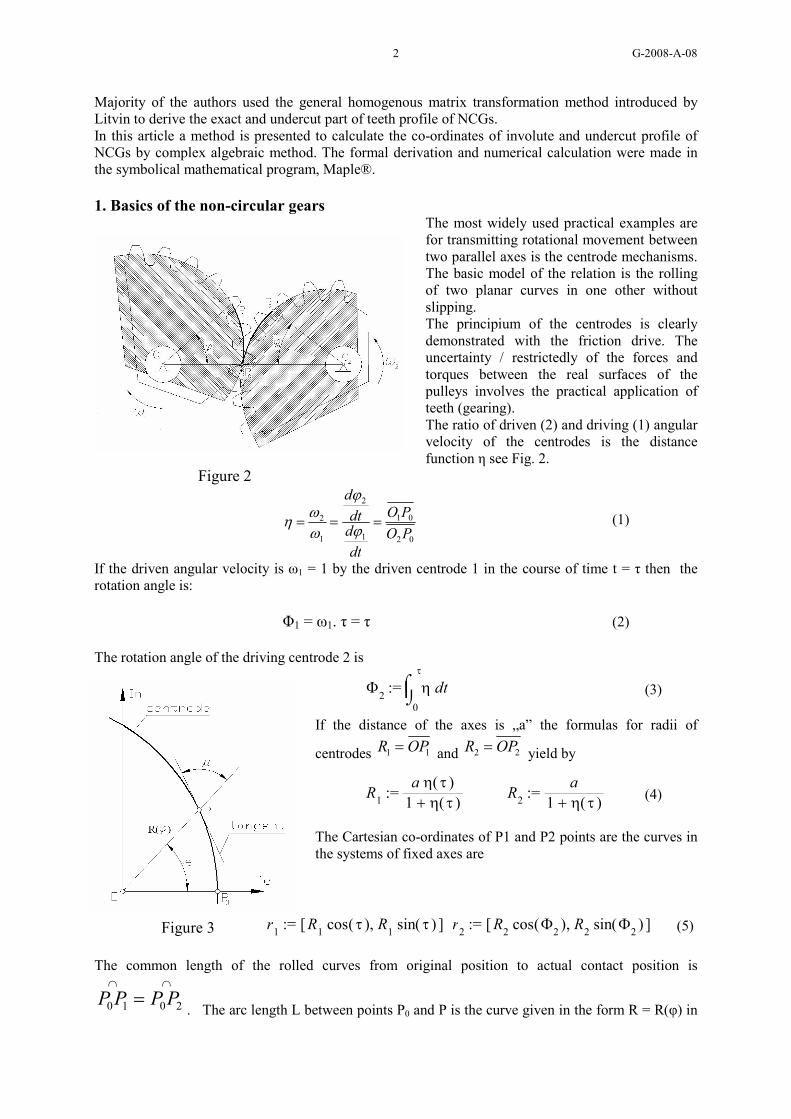
Majority of the authors used the general homogenous matrix transformation method introduced by Litvin to derive the exact and undercut part of teeth profile of NCGs. In this article a method is presented to calculate the co-ordinates of involute and undercut profile of NCGs by complex algebraic method. The formal derivation and numerical calculation were made in the symbolical mathematical program, Maple®. 1. Basics of the non-circular gears
The most widely used practical examples are for transmitting rotational movement between two parallel axes is the centrode mechanisms. The basic model of the relation is the rolling of two planar curves in one other without slipping. The principium of the centrodes is clearly demonstrated with the friction drive. The uncertainty / restrictedly of the forces and torques between the real surfaces of the pulleys involves the practical application of teeth (gearing). The ratio of driven (2) and driving (1) angular velocity of the centrodes is the distance function η see Fig. 2.
Figure 2
02
01
1
2
1
2
PO
PO
dt
ddt
d
===ϕ
ϕ
ωω
η (1)
If the driven angular velocity is ω1 = 1 by the driven centrode 1 in the course of time t = τ then the rotation angle is:
Φ1 = ω1. τ = τ (2) The rotation angle of the driving centrode 2 is
:= Φ2
d⌠⌡0
τ
η t (3)
If the distance of the axes is „a” the formulas for radii of
centrodes 11 OPR = and 22 OPR = yield by
:= R1
a ( )η τ + 1 ( )η τ := R
2
a
+ 1 ( )η τ (4)
The Cartesian co-ordinates of P1 and P2 points are the curves in the systems of fixed axes are
:= r1[ ],R1
( )cos τ R1( )sin τ := r
2[ ],R2
( )cos Φ2R2( )sin Φ2
(5)
The common length of the rolled curves from original position to actual contact position is ∩∩
= 2010 PPPP. The arc length L between points P0 and P is the curve given in the form R = R(φ) in
Figure 3

G-2008-A-08 3
a general polar equation
∫
+=
ϕ
ϕϕ0
2
2 dd
dRRL (6)
The angle of the polar radii OP and the tangent of the centrode R = R(φ) yield by
=
ϕ
µ
d
dR
Rarctan
(7)
The Fig. 4. a/ illustrate one of the real form of the NCG that were made by the author by EDM technology, see Ref. [8]) for the transfer function This study demonstrates only the mathematical basics of design of the profile of NCGs. Further explanation of design, manufacturing and measuring of the NCGs are reviewed in the References.
a./ b./
Figure 4 2. The basic rack and the generation of teeth The generating of involute profiles of the circular and non-circular gears made by the method of the basic rack. The complex co-ordinates of corner points of the rack are
:= Q0
m
− − −
π4
h ( )tan α I h ;
:= Q1
m
− + +
π4( ) + h c ( )tan α I ( ) + h c ;
:= Q2
m
− +
π4( ) + h c ( )tan α I ( ) + h c ;
:= Q3
m
+ −
π4
h ( )tan α I h (8)
:= Qi
+ Q − i 4 m π
(i = 4, 5, …, )
See: Figure. 5. (The imaginary unit is 1−=I , the profile angle is α, the module is “m”, the factor of dedendum and addendum are “h” and “h + c”, the fillet radius of rack is actually 0.)
The generation of the tooth profiles is provided due to the rolling of the rack over the centrode of the gear. P is the actual common point of the centrode of the gear and the rolling line of the rack. The pitch line of the rack and the centrode of the gear are in tangency relation at the point P. The pure rolling of the rack over the centrode is
:= η + + − 1( )cos t7
2 ( )cos 2 t9
6 ( )cos 3 t31
Figure 5
G-2008-A-08 4
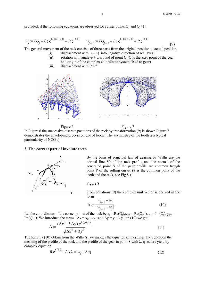
provided, if the following equations are observed for corner points Qj and Qj+1:
:= wj
+ ( ) − QjL eeee
( )I ( ) + φ µR eeee
( )I φ
:= w
+ j 1 + ( ) − Q
+ j 1L eeee
( )I ( ) + φ µR eeee
( )I φ
(9) The general movement of the rack consists of three parts from the original position to actual position
(i) displacement with (– L) into negative direction of real axes (ii) rotation with angle φ + µ around of point O (O is the axes point of the gear
and origin of the complex co-ordinate system fixed to gear) (iii) displacement with R.eI.φ
Figure 6 Figure 7 In Figure 6 the successive discrete positions of the rack by transformation (9) is shown.Figure 7 demonstrates the enveloping process on one of tooth. (The asymmetry of the tooth is a typical particularity of NCGs.)
3. The correct part of involute teeth By the basis of principal law of gearing by Willis are the normal line SP of the rack profile and the normal of the generated point S of the gear profile are common trough point P of the rolling curve. (S is the common point of the teeth and the rack, see Fig.8.) Figure 8 From equations (9) the complex unit vector is derived in the form
:= ∆ − w
+ j 1wj
− w + j 1
wj
(10)
Let the co-ordinates of the corner points of the rack be xj = Re(Qj),xj+1 = Re(Qj+1), yj = Im(Qj), yj+1 = Im(Qj+1). We introduce the terms ∆x = xj+1 - xj and ∆y = yj+1 - yj , in (10) we get
22
).()..(
yx
eyIx I
∆+∆
∆+∆=∆
+µϕ
(11)
The formula (10) obtain from the Willis’s law implies the equation of meshing. The condition the meshing of the profile of the rack and the profile of the gear in point S with λ, η scalars yield by complex equation
= + R eeee( )I φ
I ∆ λ + wj
∆ η (12)
G-2008-A-08 5
The lengths are SP=λ and Sw j=η . SP is the common normal of the profile of the rack
and the profile of the teeth. The complex equation (12) has real and imaginary part, so the two scalar solutions of equation (12) can be gained in a closed form:
:= λ − − + y
jx
+ j 1y
+ j 1xjyjL y
+ j 1L
+ ( ) − x + j 1
xj
2( ) − y
+ j 1yj
2
:= η− + − + + − yjy
+ j 1xj
2xjL x
+ j 1L y
j
2xjx
+ j 1
+ ( ) − x + j 1
xj
2( ) − y
+ j 1yj
2
(13)
The complex co-ordinates of exact involute point S are explained in closed form by:
( )
∆+∆
∆+∆
∆−−+= ++ µϕ .
22
11. ....
. IjjjjI eyIxyx
yLxyxyReS (14).
4. The undercut part of involute teeth The equidistant lines of rolling curve of gears (4) are the addendum r1 and the dedendum r2
:= r1eeee( )I φ( ) − R I h m eeee
( )I µ
(15 a./)
:= r2eeee( )I φ( ) + R I ( ) + h c m eeee
( )I µ
(15 b./)
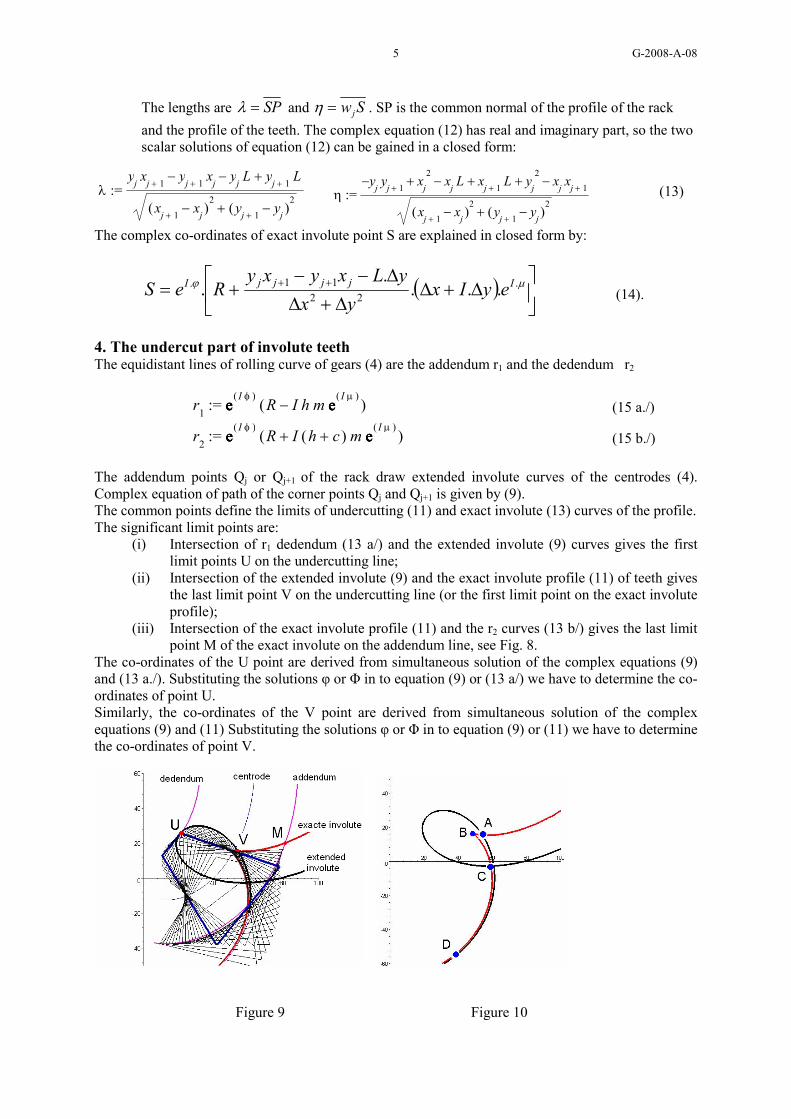
The addendum points Qj or Qj+1 of the rack draw extended involute curves of the centrodes (4). Complex equation of path of the corner points Qj and Qj+1 is given by (9). The common points define the limits of undercutting (11) and exact involute (13) curves of the profile. The significant limit points are:
(i) Intersection of r1 dedendum (13 a/) and the extended involute (9) curves gives the first limit points U on the undercutting line;
(ii) Intersection of the extended involute (9) and the exact involute profile (11) of teeth gives the last limit point V on the undercutting line (or the first limit point on the exact involute profile);
(iii) Intersection of the exact involute profile (11) and the r2 curves (13 b/) gives the last limit point M of the exact involute on the addendum line, see Fig. 8.
The co-ordinates of the U point are derived from simultaneous solution of the complex equations (9) and (13 a./). Substituting the solutions φ or Φ in to equation (9) or (13 a/) we have to determine the co-ordinates of point U. Similarly, the co-ordinates of the V point are derived from simultaneous solution of the complex equations (9) and (11) Substituting the solutions φ or Φ in to equation (9) or (11) we have to determine the co-ordinates of point V.
Figure 9 Figure 10
G-2008-A-08 6
Finally, the co-ordinates of the M point are derived from simultaneous solution of the complex equations (9) and (13 b/). Substituting the solutions φ in to (9) - or in to Φ (13 b./) - we have to determine the co-ordinates of point M. The determination of suitable solution of the equations (9) and (11) is numerically very difficult in the general case. The formal equations are originated from the real and imaginary part of (9) and (11) in the symbolic form
0),(
0),(
2
1
=Φ
=Φ
ϕϕ
f
f (14)
Figure 10 demonstrates the patches of exact involute of profile and the path of corner point of the rack. The common points of the two curves are A, C and D. The point B is the double point of the exact involute, near to the unique real intersection point A. The determinant of Jacobian of the equation system (14) is:
021
21
=
Φ∂∂
Φ∂∂
∂∂
∂∂
ff
ff
ϕϕ (15)
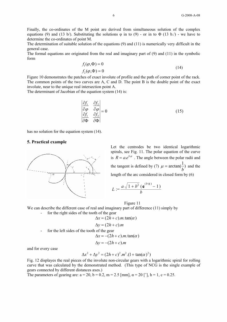
has no solution for the equation system (14). 5. Practical example
Let the centrodes be two identical logarithmic spirals, see Fig. 11. The polar equation of the curve
is ϕ.. beaR = . The angle between the polar radii and
the tangent is defined by (7) )1
arctan(b
=µ and the
length of the arc considered in closed form by (6)
:= La + 1 b2 ( ) − eeee
( )b φ1
b
Figure 11
We can describe the different case of real and imaginary part of difference (11) simply by - for the right sides of the tooth of the gear
mchy
mchx
).2(
)tan(.).2(
+=∆
+=∆ α
- for the left sides of the tooth of the gear
mchy
mchx
).2(
)tan(.).2(
+−=∆
+−=∆ α
and for every case
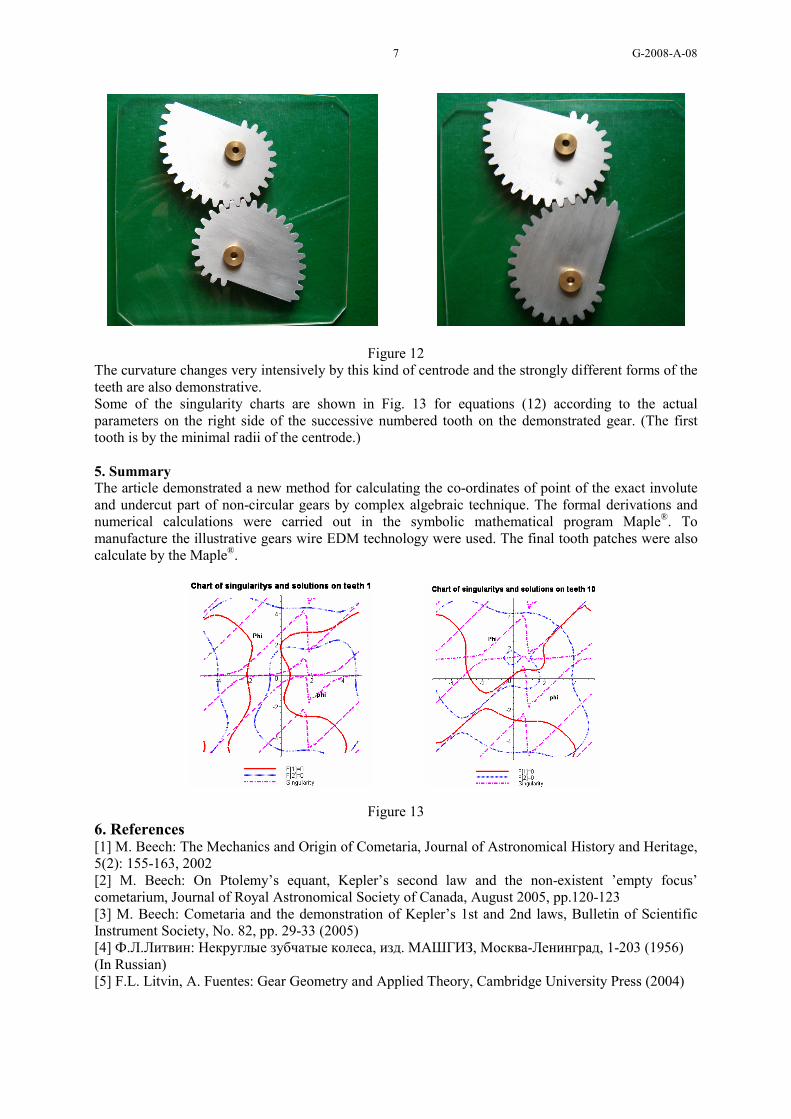
))tan(1.(.)2( 22222 α++=∆+∆ mchyx Fig. 12 displayes the real pieces of the involute non-circular gears with a logarithmic spiral for rolling curve that was calculated by the demonstrated method. (This type of NCG is the single example of gears connected by different distances axes.) The parameters of gearing are: a = 20, b = 0.2, m = 2.5 [mm], α = 20 [˚], h = 1, c = 0.25.
G-2008-A-08 7
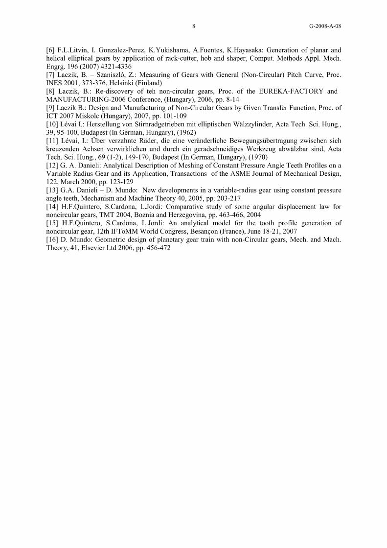
Figure 12 The curvature changes very intensively by this kind of centrode and the strongly different forms of the teeth are also demonstrative. Some of the singularity charts are shown in Fig. 13 for equations (12) according to the actual parameters on the right side of the successive numbered tooth on the demonstrated gear. (The first tooth is by the minimal radii of the centrode.) 5. Summary
The article demonstrated a new method for calculating the co-ordinates of point of the exact involute and undercut part of non-circular gears by complex algebraic technique. The formal derivations and numerical calculations were carried out in the symbolic mathematical program Maple®. To manufacture the illustrative gears wire EDM technology were used. The final tooth patches were also calculate by the Maple®.
Figure 13 6. References [1] M. Beech: The Mechanics and Origin of Cometaria, Journal of Astronomical History and Heritage, 5(2): 155-163, 2002 [2] M. Beech: On Ptolemy’s equant, Kepler’s second law and the non-existent ’empty focus’ cometarium, Journal of Royal Astronomical Society of Canada, August 2005, pp.120-123 [3] M. Beech: Cometaria and the demonstration of Kepler’s 1st and 2nd laws, Bulletin of Scientific Instrument Society, No. 82, pp. 29-33 (2005) [4] Ф.Л.Литвин: Некруглые зубчатые колеса, изд. МАШГИЗ, Москва-Ленинград, 1-203 (1956) (In Russian) [5] F.L. Litvin, A. Fuentes: Gear Geometry and Applied Theory, Cambridge University Press (2004)
G-2008-A-08 8
[6] F.L.Litvin, I. Gonzalez-Perez, K.Yukishama, A.Fuentes, K.Hayasaka: Generation of planar and helical elliptical gears by application of rack-cutter, hob and shaper, Comput. Methods Appl. Mech. Engrg. 196 (2007) 4321-4336 [7] Laczik, B. – Szaniszló, Z.: Measuring of Gears with General (Non-Circular) Pitch Curve, Proc. INES 2001, 373-376, Helsinki (Finland) [8] Laczik, B.: Re-discovery of teh non-circular gears, Proc. of the EUREKA-FACTORY and MANUFACTURING-2006 Conference, (Hungary), 2006, pp. 8-14 [9] Laczik B.: Design and Manufacturing of Non-Circular Gears by Given Transfer Function, Proc. of ICT 2007 Miskolc (Hungary), 2007, pp. 101-109 [10] Lévai I.: Herstellung von Stirnradgetrieben mit elliptischen Wälzzylinder, Acta Tech. Sci. Hung., 39, 95-100, Budapest (In German, Hungary), (1962) [11] Lévai, I.: Über verzahnte Räder, die eine veränderliche Bewegungsübertragung zwischen sich kreuzenden Achsen verwirklichen und durch ein geradschneidiges Werkzeug abwälzbar sind, Acta Tech. Sci. Hung., 69 (1-2), 149-170, Budapest (In German, Hungary), (1970) [12] G. A. Danieli: Analytical Description of Meshing of Constant Pressure Angle Teeth Profiles on a Variable Radius Gear and its Application, Transactions of the ASME Journal of Mechanical Design, 122, March 2000, pp. 123-129 [13] G.A. Danieli – D. Mundo: New developments in a variable-radius gear using constant pressure angle teeth, Mechanism and Machine Theory 40, 2005, pp. 203-217 [14] H.F.Quintero, S.Cardona, L.Jordi: Comparative study of some angular displacement law for noncircular gears, TMT 2004, Boznia and Herzegovina, pp. 463-466, 2004 [15] H.F.Quintero, S.Cardona, L.Jordi: An analytical model for the tooth profile generation of noncircular gear, 12th IFToMM World Congress, Besançon (France), June 18-21, 2007 [16] D. Mundo: Geometric design of planetary gear train with non-Circular gears, Mech. and Mach. Theory, 41, Elsevier Ltd 2006, pp. 456-472