Design of Medical Devices for Diagnostics in the ...
113
University of Nebraska - Lincoln DigitalCommons@University of Nebraska - Lincoln Mechanical (and Materials) Engineering -- Dissertations, eses, and Student Research Mechanical & Materials Engineering, Department of Spring 4-21-2016 Design of Medical Devices for Diagnostics in the Gastrointestinal System Charles R. Welch University of Nebraska-Lincoln, [email protected] Follow this and additional works at: hp://digitalcommons.unl.edu/mechengdiss Part of the Analytical, Diagnostic and erapeutic Techniques and Equipment Commons , Biomedical Devices and Instrumentation Commons , and the Mechanical Engineering Commons is Article is brought to you for free and open access by the Mechanical & Materials Engineering, Department of at DigitalCommons@University of Nebraska - Lincoln. It has been accepted for inclusion in Mechanical (and Materials) Engineering -- Dissertations, eses, and Student Research by an authorized administrator of DigitalCommons@University of Nebraska - Lincoln. Welch, Charles R., "Design of Medical Devices for Diagnostics in the Gastrointestinal System" (2016). Mechanical (and Materials) Engineering -- Dissertations, eses, and Student Research. 95. hp://digitalcommons.unl.edu/mechengdiss/95
-
Upload
khangminh22 -
Category
Documents
-
view
3 -
download
0
Transcript of Design of Medical Devices for Diagnostics in the ...

University of Nebraska - LincolnDigitalCommons@University of Nebraska - LincolnMechanical (and Materials) Engineering --Dissertations, Theses, and Student Research
Mechanical & Materials Engineering, Departmentof
Spring 4-21-2016
Design of Medical Devices for Diagnostics in theGastrointestinal SystemCharles R. WelchUniversity of Nebraska-Lincoln, [email protected]
Follow this and additional works at: http://digitalcommons.unl.edu/mechengdiss
Part of the Analytical, Diagnostic and Therapeutic Techniques and Equipment Commons,Biomedical Devices and Instrumentation Commons, and the Mechanical Engineering Commons
This Article is brought to you for free and open access by the Mechanical & Materials Engineering, Department of at DigitalCommons@University ofNebraska - Lincoln. It has been accepted for inclusion in Mechanical (and Materials) Engineering -- Dissertations, Theses, and Student Research by anauthorized administrator of DigitalCommons@University of Nebraska - Lincoln.
Welch, Charles R., "Design of Medical Devices for Diagnostics in the Gastrointestinal System" (2016). Mechanical (and Materials)Engineering -- Dissertations, Theses, and Student Research. 95.http://digitalcommons.unl.edu/mechengdiss/95
DESIGN OF MEDICAL DEVICES FOR DIAGNOSTICS IN THE
GASTROINTESTINAL SYSTEM
by
Charles Ross Welch
A THESIS
Presented to the Faculty of
The Graduate College at the University of Nebraska
In Partial Fulfillment of Requirements
For the Degree of Master of Science
Major: Mechanical Engineering and Applied Mechanics
Under the Supervision of Professor Carl A. Nelson
Lincoln, Nebraska
May, 2016
DESIGN OF MEDICAL DEVICES FOR DIAGNOSTICS IN THE
GASTROINTESTINAL SYSTEM
Charles Ross Welch, M.S.
University of Nebraska, 2016
Advisor: Carl A. Nelson
This thesis presents the design, controls, and testing of two systems: a novel colonoscope
locomotion design for diagnostics, and a biosensor capsule that implants a sensor in the
small intestine. Each system requires special design considerations for use in the
gastrointestinal system.
Colonoscopy procedures are recommended as a screening for colon cancer and
related conditions after the age of 50. The need for an improved colonoscope that reduces
the colonoscopy time and patient discomfort is apparent. The semi-autonomous device
presented here could likely reduce the colonoscopy procedure time by allowing the
physician to focus more on the diagnosis and less on the procedure itself. It greatly reduces
shear forces experienced on the colon wall, reducing pain and discomfort experienced by
the patient.
The biosensor capsule presented in this thesis is also used for diagnostics. The
device implants a sensor into the intestine wall, a sensor that could be used to track pH
levels, temperature, or possibly even caloric intake. This thesis explores the transport
capsule design and some of the electrical hardware used.
The thesis is divided into two parts, exploring both devices. Part one focuses on the
design and testing of the colonoscope device, while part two focuses on the biosensor
capsule device. In each part, the motivation behind each of the devices and the related
works being accomplished at other research institutions are described. Each part then
explores the design of the respective device and the reasons behind some of the design
choices presented. For both projects, a significant amount of bench-top testing was
performed; an in-depth look at the test methods and setup used, followed by the results of
each is given. Results for the colonoscopy robot show full capability of traversing a 5-foot
porcine colon with four 90-degree turns and potential for full automation. Results for the
biosensor capsule device demonstrate the capability of sensor plate implantation and
attachment lasting more than 40 hours. Finally, the conclusion section describes the future
work associated with the device as well as the possibilities and accomplishments achieved
through the design of each device, respectively.
iv
ACKNOWLEDGEMENTS
I would like to first say thanks to Dr. Carl Nelson, being my advisor in both of these
projects. Thanks for the autonomy to work on these projects on my own time scale. Also,
a huge thanks to Dr. Benjamin Terry who was the principal investigator in the capsule
project and to Dr. Prithviraj Dasgupta who was the principal investigator in the
colonoscopy project. They provided a lot of guidance in many design and testing decisions.
Thanks to the Animal Science department on East Campus at the University of
Nebraska for donating colon and small intestine tissue used for the tests described in this
thesis. Thanks to the other students who worked alongside me in these projects: Hossein
Dehghani, Weston Lewis, Jared Kaser, Wanchuan Xie, and Zachary Bram. Many of the
design and testing decisions should be attributed directly to them and the graduate and
undergraduate students before them who worked on these projects as well. Finally, thanks
to my wife for her immeasurable support, and to my family for their encouragement and
support in pursuing a master’s degree.
v
Table of Contents
Table of Contents ................................................................................................................ v
List of Figures ................................................................................................................... vii
List of Tables ................................................................................................................... x
Part I: Colonoscopy Robot .................................................................................................. 1
Chapter 1: Introduction ................................................................................................... 2
Chapter 2: Motivation ..................................................................................................... 4
Chapter 3: Mechanical Design ........................................................................................ 9
3.1 Latex Tubing........................................................................................................ 10
3.2 Sealing Mechanism.............................................................................................. 11
3.3 Camera ................................................................................................................. 13
3.3.1 Camera wiring ............................................................................................... 14
3.4 Pneumatic Controls.............................................................................................. 16
3.5 Contributions ....................................................................................................... 17
Chapter 4: Bench-Top Tests ...................................................................................... 18
4.1 Tubing Expansion Ratio ...................................................................................... 18
4.2 Heat Effects ......................................................................................................... 19
4.3 Tube Burst Pressure ............................................................................................. 20
4.4 Device Benchtop Tests ........................................................................................ 20
4.4.1 Preliminary Testing ....................................................................................... 20
4.4.2 In Vitro Colon Tests...................................................................................... 22
4.5 Data Acquisition .................................................................................................. 23
4.5.1 LabVIEW Virtual Instrument ....................................................................... 23
4.5.2 Sensor Calibration ......................................................................................... 24
4.5.3 Data Acquisition Results and Discussion ..................................................... 25
4.6 Camera Functionality .......................................................................................... 26
4.7 Contributions ....................................................................................................... 26
Part II: Biosensor Capsule ................................................................................................ 27
Chapter 5: Introduction and Motivation ........................................................................ 28
Chapter 6: Capsule Design ............................................................................................ 32
6.1 Design Goals....................................................................................................... 33
vi
6.2 Capsule Geometry ............................................................................................... 34
6.3 Electronics and PCB ............................................................................................ 36
6.4 Wax Valve and Nichrome Wire .......................................................................... 37
6.5 Force Balance ...................................................................................................... 41
6.6 O-rings ................................................................................................................. 43
6.7 Vacuum Chamber ................................................................................................ 43
6.8 Contributions ....................................................................................................... 44
Chapter 7: Capsule Testing ........................................................................................... 45
7.1 Wax Melting Point............................................................................................... 45
7.2 Capsule Seal Tests ............................................................................................... 46
7.3 Seal Geometry Tests ............................................................................................ 48
7.4 In Vitro Tests ....................................................................................................... 49
7.4.1 Vacuum volume and added mucus ............................................................... 49
7.4.2 Tissue aspiration and capsule-sensor plate ejection force ............................ 51
7.5 In Vivo Tests ........................................................................................................ 53
7.5.1 In vivo test November 19th, 2015 .................................................................. 53
7.5.2 In vivo test February 9th, 2016 ...................................................................... 57
7.5.3 In vivo test March 29th, 2016 ........................................................................ 61
7.6 Contributions ....................................................................................................... 63
Chapter 8: Discussion and Conclusion ......................................................................... 64
References ..................................................................................................................... 69
Appendix ....................................................................................................................... 73
vii
List of Figures
Figure 2 - 1: A simulation of loop formation ...................................................................... 5
Figure 3 - 1: Colonoscopy robot tip parts ........................................................................... 9
Figure 3 - 2: Sealing mechanism isometric view .............................................................. 12
Figure 3 - 3: Sealing mechanism side view ...................................................................... 12
Figure 3 - 4: Sealing mechanism exploded view .............................................................. 13
Figure 3 - 5: Cable inside canister peels off of plastic due to spray adhesive .................. 14
Figure 3 - 6: CR tip able to travel a full 5 feet with wiring canister ................................. 15
Figure 3 - 7: Electrical and pneumatic circuits controlling the robot ............................... 16
Figure 4 - 1: Representation of the heat-effects test ......................................................... 19
Figure 4 - 2: Benchtop test configuration ......................................................................... 21
Figure 4 - 3: Benchtop test of colonoscopy robot in an excised porcine colon. ............... 22
Figure 4 - 4: LabVIEW VI layout ..................................................................................... 24
Figure 4 - 5: Robot pressure and flow data inside excised porcine tissue ........................ 25
Figure 4 - 6: Brief visibility inside the colonoscopy robot ............................................... 26
Figure 6 - 1: Capsule layout. ............................................................................................. 32
Figure 6 - 2: Unloaded capsule (no applied vacuum). ...................................................... 33
Figure 6 - 3: Capsule circuit diagram ............................................................................... 35
Figure 6 - 4: Capsule PCB layout. R1 = 1k Ohms and R2 = 10k Ohms .......................... 36
Figure 6 - 5: Nichrome wire wrapped around copper tube in preliminary assembly ....... 37
Figure 6 - 6: Circuit used to measure internal resistance. ................................................. 39
Figure 6 - 7: Power dissipated as a function of load resistance ........................................ 40
viii
Figure 6 - 8: Force balance of vacuum and spring forces on the sensor plate. ................. 41
Figure 7 - 1: Wax melting point test setup ........................................................................ 45
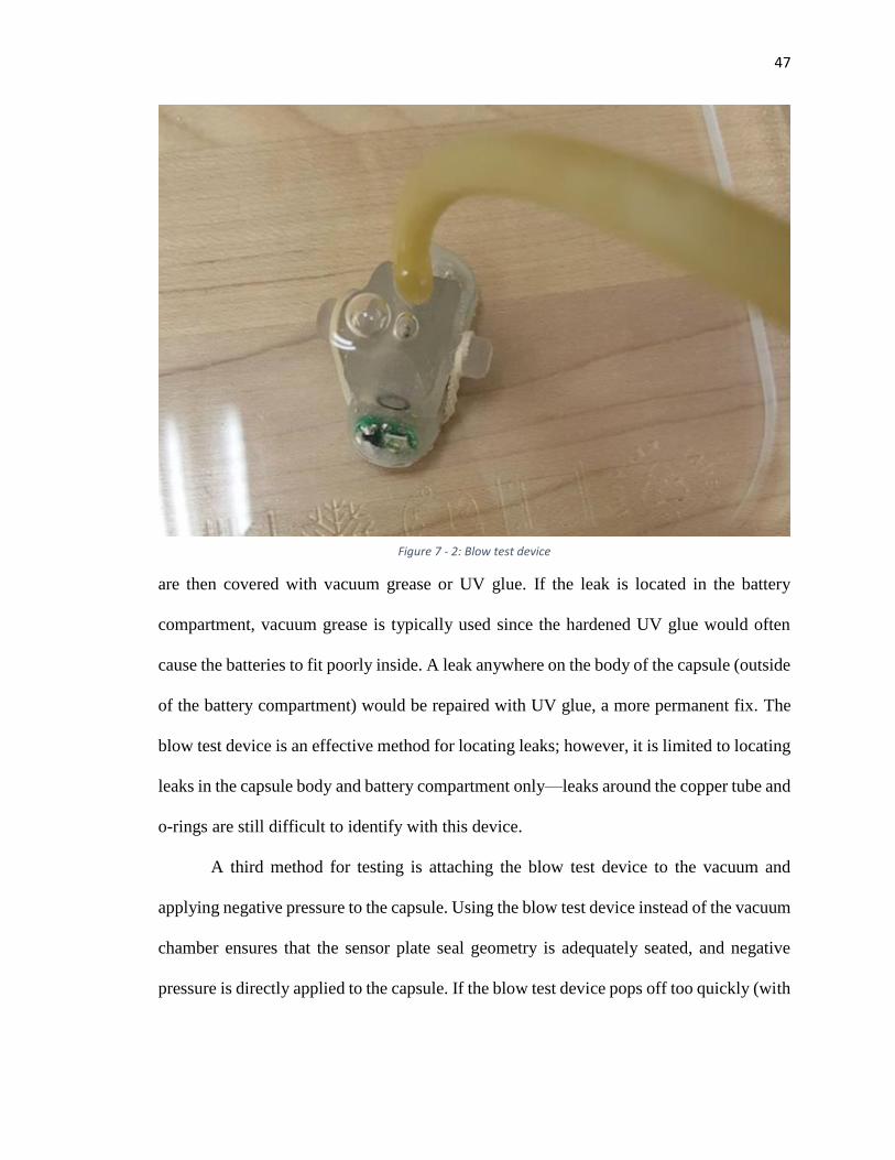
Figure 7 - 2: Blow test device ........................................................................................... 47
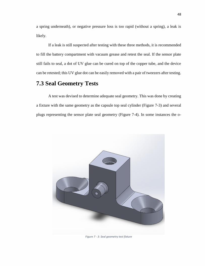
Figure 7 - 3: Seal geometry test fixture ............................................................................ 48
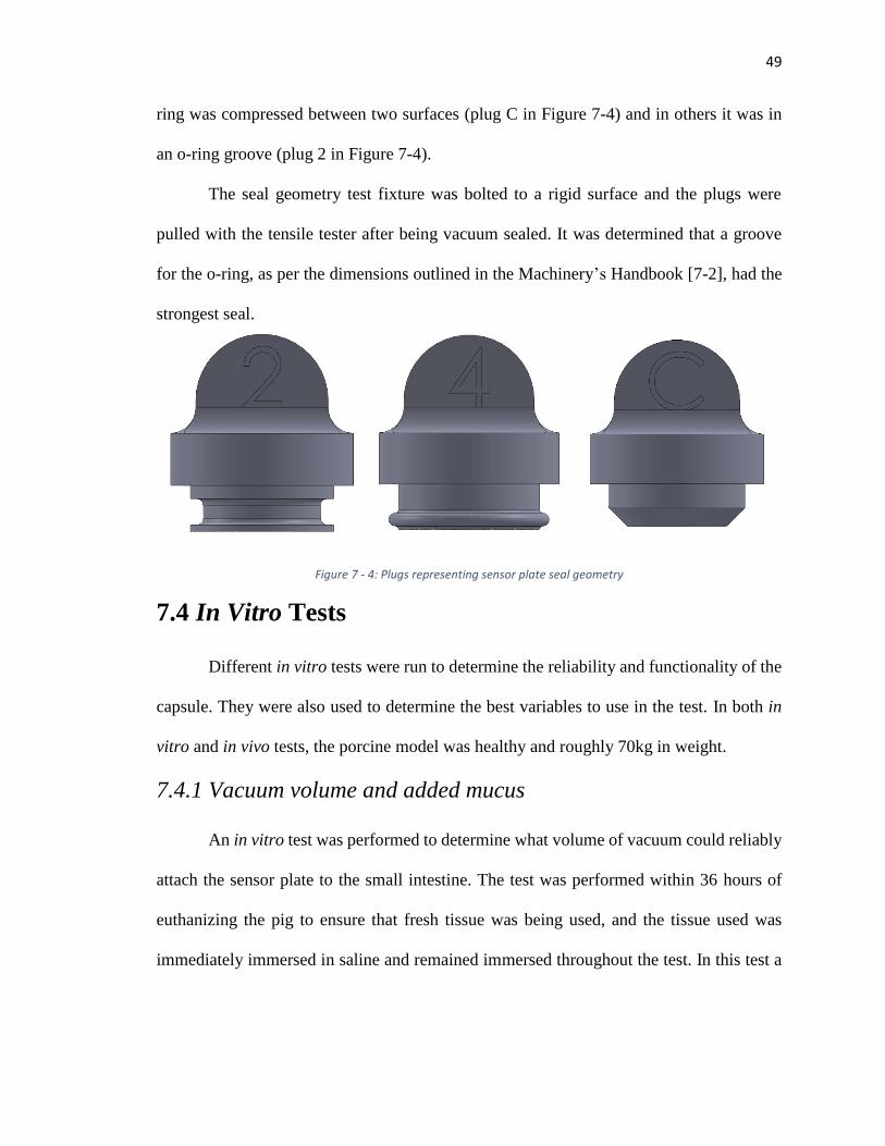
Figure 7 - 4: Plugs representing sensor plate seal geometry ............................................. 49
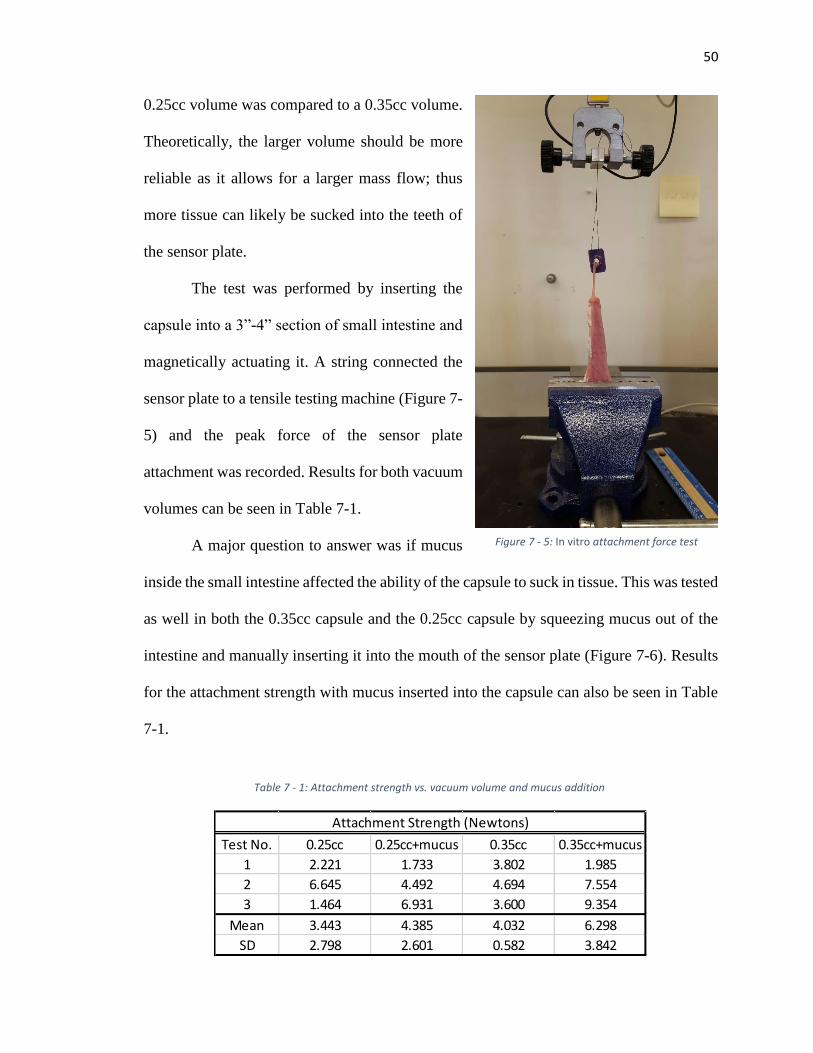
Figure 7 - 5: In vitro attachment force test ....................................................................... 50
Figure 7 - 6: Mucus added to capsule ............................................................................... 51
Figure 7 - 7: Succesful tissue aspiration ........................................................................... 52
Figure 7 - 8: Sensor plate ejection test .............................................................................. 52
Figure 7 - 9: Capsule inserted into intestine with radiopaque marker sutured ................. 54
Figure 7 -11: X-ray 40 hours after surgery ....................................................................... 55
Figure 7 - 10: X-ray 4 hours after surgery ........................................................................ 55
Figure 7 - 12: X-ray 52 hours after surgery ...................................................................... 56
Figure 7 - 13: Capsules used in February 9th test ............................................................. 57
Figure 7 - 14: X-ray 4 hours after surgery ........................................................................ 58
Figure 7 - 15: X-ray 16 hours after surgery ...................................................................... 58
Figure 7 - 16: X-ray 28 hours after surgery ...................................................................... 59
Figure 7 - 18: X-ray 52 hours after surgery ...................................................................... 60
Figure 7 - 17: Successful tissue aspiration in vivo. .......................................................... 60
Figure 7 - 19: Capsules in intestine after applying surgical clips ..................................... 61
Figure 7 - 20: X-ray taken 4 hours after surgery .............................................................. 62
Figure 8 - 1: Arc representing tissue sucked into capsule ................................................ 66
Figure 8 - 2: Tissue measurement ..................................................................................... 67
ix
Figure 8 - 3: Capsule concept using a face seal to eliminate the need of a spring. .......... 68
x
List of Tables
Table 2 - 1: Comparison table of related devices. .............................................................. 7
Table 4 - 1: Calibration data for Omron Electronics Inc-EMC Div D6F-10A6-000........ 24
Table 5 - 1: Attachment mechanisms of different organisms. .......................................... 30
Table 7 - 1: Attachment strength vs. vacuum volume and mucus addition ...................... 50
1
Part I: Colonoscopy Robot
2
Chapter 1: Introduction
Hundreds of thousands of people each year die from colon cancer worldwide. It is
one of the leading causes of cancer-related deaths in the United States. Preventive measures
through diagnostics are the safest means of detecting cancer early. When the cancer is
detected early, as with other cancers, it gives a physician the chance of removing the
cancerous tissue before it can spread to the rest of the body. The cancer can typically be
detected through a diagnostic endoscope inserted into the anus. A camera on the end of the
endoscope shows the physician a live video feed of the inside of the colon as he maneuvers
it to the cecum. A so-called working channel in the endoscope allows the introduction of
tools which help the physician remove and diagnose polyps found within the colon (tissue
interaction).
Due to the nature of inserting the endoscope into the anus and the difficulty of
maneuvering the endoscope from the anus to the cecum, shear and tip forces cause pain
and discomfort for the patient and can cause perforation in some cases. This thesis explores
an alternative endoscope design that reduces shear forces exerted on the colon wall. The
design includes a novel pneumatic means of locomotion through the colon. The device,
shown in Figure [1-?], is inserted into the anus, and the locomotion is created by inflating
a rolled-up latex tube housed inside the device tip. Since the inflated tubing is stationary,
it significantly reduces shear forces on the colon wall.
Chapter 2 of this thesis will take a closer look at the current technology and new
devices being researched to improve the colonoscopy process. In Chapter 3, the
mechanical design is discussed and the general locomotion technique is described.
3
Chapter 4 discusses the control system used to advance the device through the colon.
Chapter 5 presents several benchtop experiments performed to explore the safety and
capability of the device. Finally, Chapter 6 discusses the results of the experiments and
offers some concluding remarks.
4
Chapter 2: Motivation
Colorectal cancer (CRC) is one of the leading causes of cancerous deaths in the
United States. In 2010, CRC claimed over 52,000 lives, and over 137,000 were diagnosed
with the deadly cancer [2-1]. It is the most deadly cancer after lung cancer, killing more
nonsmokers than any other cancer. If it is diagnosed at early stages, the 5-year survival rate
is more than 88% [2-2].The survival rate is higher at early stages because the cancer forms
as pre-cancerous polyps first. Physicians recommend a colon screening every ten years as
the first defense against cancer. Other screening procedures include high-sensitivity fecal
occult blood testing, sigmoidoscopy every 5 years, CT colonography, fecal DNA testing,
and double-contrast barium enema [2-1, 2-3]. In a study on physicians’ screening
recommendations, 95% routinely recommended colonoscopy as a preventive measure to
CRC. It remains the most recommended screening procedure today [2-3].
Even though there are effective ways to screen against CRC, not all seniors report
for their 10-year screening. In fact, only about two-thirds of adults ages 50-75 are up-to-
date on their colon cancer checkups. From 2002 to 2010, CRC screening increased from
54% to 65%, and most of that has been through increased use of colonoscopy. Since 2010,
the rate of increase has slowed substantially, rising to only 65.1% in 2012 [2-4].
Researchers believe that improving patient experience during colonoscopy could further
increase the percentage of regular CRC screenings.
Complications of colonoscopy could be a large factor in the patients’ decision of
whether or not to receive a colonoscopy. Some of the complications associated with
colonoscopy include abdominal pain, discomfort, and colon perforation. In one study, 5.4%
5
of patients experienced discomfort during colonoscopy [2-17]; in another, 11% of patients
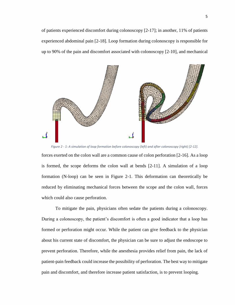
experienced abdominal pain [2-18]. Loop formation during colonoscopy is responsible for
up to 90% of the pain and discomfort associated with colonoscopy [2-10], and mechanical
forces exerted on the colon wall are a common cause of colon perforation [2-16]. As a loop
is formed, the scope deforms the colon wall at bends [2-11]. A simulation of a loop
formation (N-loop) can be seen in Figure 2-1. This deformation can theoretically be
reduced by eliminating mechanical forces between the scope and the colon wall, forces
which could also cause perforation.
To mitigate the pain, physicians often sedate the patients during a colonoscopy.
During a colonoscopy, the patient’s discomfort is often a good indicator that a loop has
formed or perforation might occur. While the patient can give feedback to the physician
about his current state of discomfort, the physician can be sure to adjust the endoscope to
prevent perforation. Therefore, while the anesthesia provides relief from pain, the lack of
patient-pain feedback could increase the possibility of perforation. The best way to mitigate
pain and discomfort, and therefore increase patient satisfaction, is to prevent looping.
Figure 2 - 1: A simulation of loop formation before colonoscopy (left) and after colonoscopy (right) [2-12].
6
Given this challenge of preventing looping, many researchers are exploring new
methods of locomotion inside the colon. This is no easy task; the colon is slippery,
irregular, collapsed, and varies in diameter throughout its 5-foot length [2-13]. Colobot is
a semi-autonomous endoscope tip that bends to follow the axial curvature of the colon
based on three non-contact distance sensors [2-5]. While in theory this reducesshear forces
between the tip of the endoscope and the colon, it provides no solution for the looping
caused by feeding the endoscope manually from outside of the body.
An earthworm-based creeping robot is introduced in [2-6]. The earthworm
approach in theory could prevent looping since the device is essentially pulling itself into
the colon instead of being pushed in; however, this device is very complex since it employs
four small DC motors, bringing all four into the colon with it. Also, maintaining adequate
friction is difficult for this robot due to the mucous layer inside the colon.
The Cath-Cam presented in [2-7] uses a catheter and guidewires to move a camera
through the colon. This method significantly reduced the forces exerted on the colon wall,
but it also lacks appropriate tissue interaction needed to replace the current colonoscope.
Other diagnostics-only systems include the Aer-O-Scope and the Endotics System™. The
Aer-O-Scope displays an innovative locomotion technique where two balloons are inflated,
one as an anchor just inside the rectum as another as a means of locomotion [2-8]. Air is
introduced between the two balloons, advancing the distal balloon (and the endoscope tip)
through the colon. While this setup reduces forces experienced on the colon wall,
researchers in one experiment found that it only reached
7
the cecum 83% of the time [2-8].
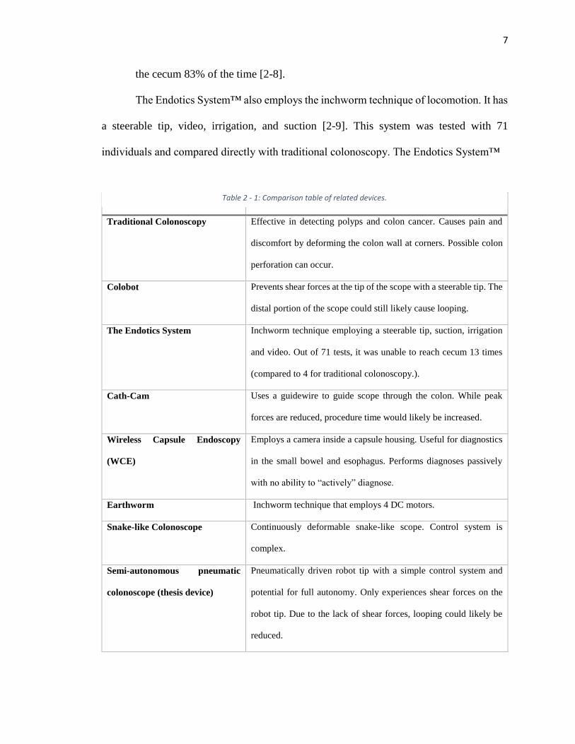
The Endotics System™ also employs the inchworm technique of locomotion. It has
a steerable tip, video, irrigation, and suction [2-9]. This system was tested with 71
individuals and compared directly with traditional colonoscopy. The Endotics System™
Device Strengths/Deficiencies
Traditional Colonoscopy Effective in detecting polyps and colon cancer. Causes pain and
discomfort by deforming the colon wall at corners. Possible colon
perforation can occur.
Colobot Prevents shear forces at the tip of the scope with a steerable tip. The
distal portion of the scope could still likely cause looping.
The Endotics System Inchworm technique employing a steerable tip, suction, irrigation
and video. Out of 71 tests, it was unable to reach cecum 13 times
(compared to 4 for traditional colonoscopy.).
Cath-Cam Uses a guidewire to guide scope through the colon. While peak
forces are reduced, procedure time would likely be increased.
Wireless Capsule Endoscopy
(WCE)
Employs a camera inside a capsule housing. Useful for diagnostics
in the small bowel and esophagus. Performs diagnoses passively
with no ability to “actively” diagnose.
Earthworm Inchworm technique that employs 4 DC motors.
Snake-like Colonoscope Continuously deformable snake-like scope. Control system is
complex.
Semi-autonomous pneumatic
colonoscope (thesis device)
Pneumatically driven robot tip with a simple control system and
potential for full autonomy. Only experiences shear forces on the
robot tip. Due to the lack of shear forces, looping could likely be
reduced.
Table 2 - 1: Comparison table of related devices.
8
(ES) was unable to reach the cecum in 13 patients, compared with only 4 patients using
traditional colonoscopy. The ES device is also much slower with an average time of 45
minutes compared to only 24 minutes in traditional colonoscopy [2-9].
A snake-like colonoscope was developed in [2-14]; this device acts like a
continuously deformable backbone, with several links capable of two-degree-of-freedom
motion. While this device shows potential for reducing shear forces and preventing
looping, the control system, overall design, and kinematics are much more complex than
the device described in this thesis [2-14] [2-15].
Endoscopy is also being researched in the form of a capsule. Wireless capsule
endoscopy (WCE) offers the capability of diagnostics throughout the entire gastrointestinal
tract [5-11]; however, WCE is also a diagnostics-only system and does not offer any tissue
interaction capabilities, nor can one generally control the capsule position.
A comparison table highlights the key features of each of the aforementioned
designs including the design presented in this thesis along with some of the strengths and/or
deficiencies of each. While the designs are all quite innovative, no solution has been able
to prove itself as a direct replacement for the traditional colonoscopy. Many of them are
either a diagnostics-only system, offer little potential for tissue interaction, or appear to be
overly complex. The colonoscopy device presented here offers a new look at an innovative
locomotion technique that presents new possibilities for diagnostics and future tissue
interaction. The locomotion technique described in this thesis reduces shear forces inside
the colon and eliminates looping.
9
Chapter 3: Mechanical Design
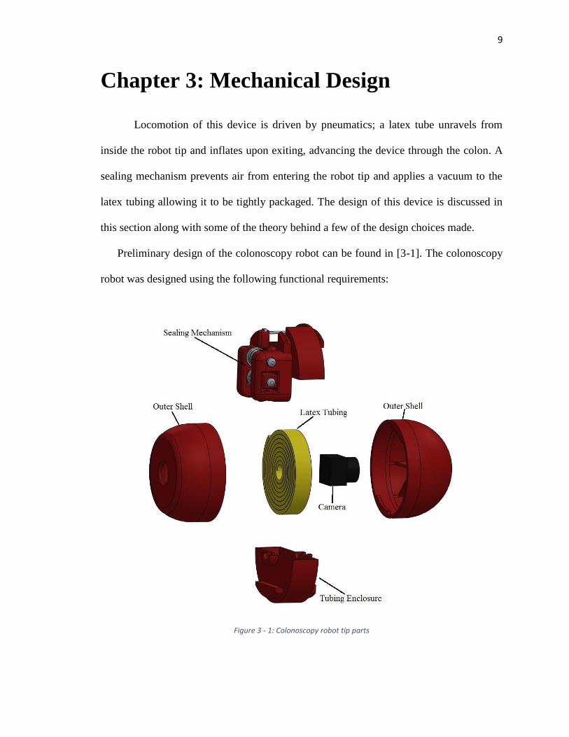
Locomotion of this device is driven by pneumatics; a latex tube unravels from
inside the robot tip and inflates upon exiting, advancing the device through the colon. A
sealing mechanism prevents air from entering the robot tip and applies a vacuum to the
latex tubing allowing it to be tightly packaged. The design of this device is discussed in
this section along with some of the theory behind a few of the design choices made.
Preliminary design of the colonoscopy robot can be found in [3-1]. The colonoscopy
robot was designed using the following functional requirements:
Figure 3 - 1: Colonoscopy robot tip parts
10
Device must be able to travel from the anus of a patient to the cecum (roughly 5
feet)
Device diameter must be small enough to fit into the anus (although this is
somewhat ambiguous)
Device must provide visual diagnostics
Device must be able to turn 90° in any direction
Following these requirements, the final device was designed as shown in Figure 3-1. The
body of the robot includes five main parts: the latex tubing, sealing mechanism, camera,
tubing enclosure, and outer shell. Design considerations for each will be discussed in their
subsequent subsections.
3.1 Latex Tubing
The latex tubing used in this device was purchased from Kent Elastomer Products,
Inc. Colon dimensions provide a constraint for the dimensions of the tubing as the
maximum unconstrained inflated tubing diameter prior to rupture should not be greater
than or equal to the diameter of the colon. The tubing wall thickness was also an important
consideration, as it impacted the length of the tubing able to fit inside the tubing enclosure.
After iteratively testing different latex tubing, it was determined that the natural
rubber latex tubing with an inner diameter of 1/8” and wall thickness of 1/32” would work
well in this device. More information on the mechanical properties of this tubing can be
found in Appendix A-3-1. These dimensions allowed a linear expansion ratio of 3.6:1 and
a diameter expansion ratio of about 6:1 or less. This satisfies the requirements of the
inflated tubing being smaller in diameter than the diameter of the colon.
11
Since 1.5m of travel was required of the colonoscopy robot, a tubing length of
0.417m (due to the expansion ratio, 1.5m/3.6 = 0.417m) would allow the robot to travel the
entire distance of the colon. The sealing mechanism allowed the tubing on the proximal
side to be vacuumed, reducing the bulkiness of the tubing stored in the tubing enclosure.
An adequate diameter for the tubing enclosure was approximated by the Archimedean
spiral equation [3-2]:
𝑟 = 𝑎𝜃 (1)
where 𝑟 is the outer radius, 𝑎 is the distance between each arm of the spiral (i.e. 𝑑𝑟
𝑑𝜃),
and 𝜃 is the total revolutions of the spiral. Since 𝑎 is unknown, it can be found
experimentally by counting the number of revolutions, measuring the diameter of the
spiral and then solving equation (1) for 𝑎. After vacuuming the tubing to decrease the
bulk, the tubing was rolled around a 2.86mm post for 8 revolutions. The diameter was
measured at 31.75mm, and 𝑎 is calculated as follows:
𝑎 = 31.75/2
8∗2𝜋= 0.316 (2)
The arc length of the Archimedean spiral can be calculated as follows:
𝑠(𝜃) =1
2𝑎(𝜃√1 + 𝜃2 + 𝑠𝑖𝑛ℎ−1(𝜃))
Using this equation, the required length of tubing (0.417m) can fit inside of a cylinder with
a radius of 16.1mm. This radius was rounded up to 17mm in the design to give it a little
more travel distance.
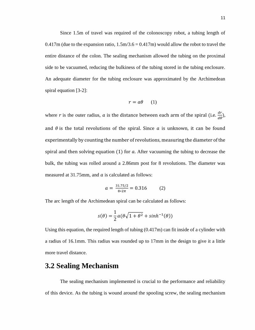
3.2 Sealing Mechanism
The sealing mechanism implemented is crucial to the performance and reliability
of this device. As the tubing is wound around the spooling screw, the sealing mechanism
12
creates a vacuum inside the latex tubing, allowing the air to be removed and the bulkiness
to be diminished. As the robot advances and the latex is unspooling, the sealing mechanism
prevents air from entering into the robot tip. Tests have shown that when air enters into the
robot tip, the latex tubing no longer can unspool itself, preventing advancement of the
device. Since this is such an important part of the product, it deserves a detailed discussion.
The isometric figure shown in Figure 3-2 gives a closer look at the sealing mechanism
(SM) used in this device. The SM consists of two sets of three bearings. One of those sets
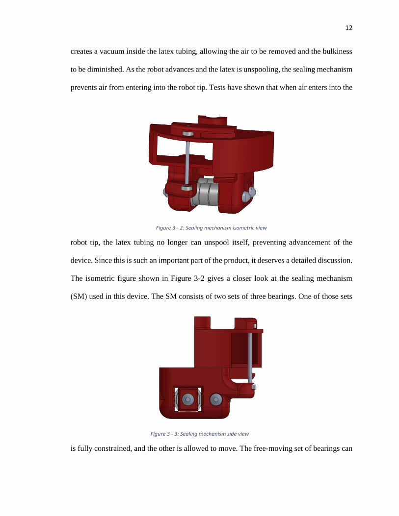
is fully constrained, and the other is allowed to move. The free-moving set of bearings can
Figure 3 - 3: Sealing mechanism side view
Figure 3 - 2: Sealing mechanism isometric view
13
move towards or away from the fixed set by means of set screws. This, in essence, pinches
the tubing together, creating a seal in the tubing that prevents air from entering into the
robot tip. The tightness of the screws is able to be adjusted as needed when the latex tubing
does not dispense properly. If the set screws are too tight, proper dispensing will not ovvure
and the latex tubing will likely burst before dispensing. A side view of the SM illustrates
the fixed and moving bearings in Figure 3-3. The other, smaller bar shown in Figure 3-3 is
a tool used to redirect the tubing as it is being unspooled from the robot tip. This allows for
a smooth release of the latex tubing from the robot tip.
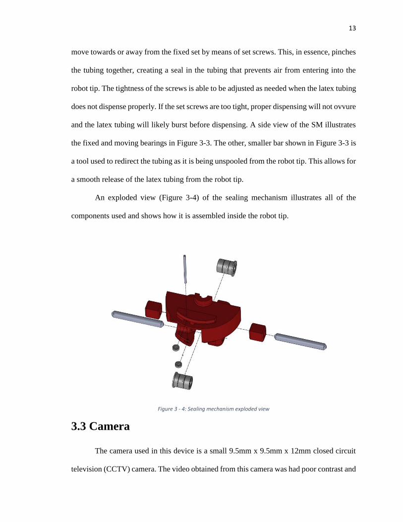
An exploded view (Figure 3-4) of the sealing mechanism illustrates all of the
components used and shows how it is assembled inside the robot tip.
3.3 Camera
The camera used in this device is a small 9.5mm x 9.5mm x 12mm closed circuit
television (CCTV) camera. The video obtained from this camera was had poor contrast and
Figure 3 - 4: Sealing mechanism exploded view
14
was often fuzzy. Even when external lights were used to illuminate the colon, the camera
did not provide exceptional video because the focal length was not short enough. While
the camera used in this study was commensurate for this project, a better camera should be
explored if the device is to be further improved.
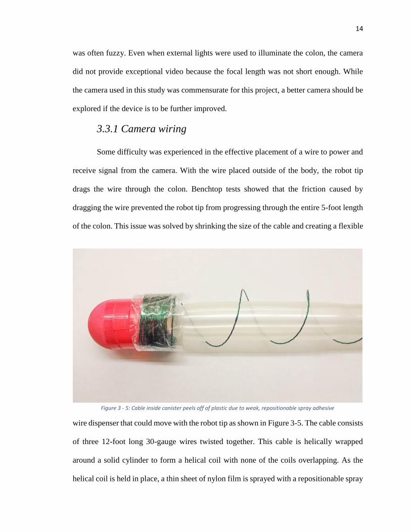
3.3.1 Camera wiring
Some difficulty was experienced in the effective placement of a wire to power and
receive signal from the camera. With the wire placed outside of the body, the robot tip
drags the wire through the colon. Benchtop tests showed that the friction caused by
dragging the wire prevented the robot tip from progressing through the entire 5-foot length
of the colon. This issue was solved by shrinking the size of the cable and creating a flexible
wire dispenser that could move with the robot tip as shown in Figure 3-5. The cable consists
of three 12-foot long 30-gauge wires twisted together. This cable is helically wrapped
around a solid cylinder to form a helical coil with none of the coils overlapping. As the
helical coil is held in place, a thin sheet of nylon film is sprayed with a repositionable spray
Figure 3 - 5: Cable inside canister peels off of plastic due to weak, repositionable spray adhesive
15
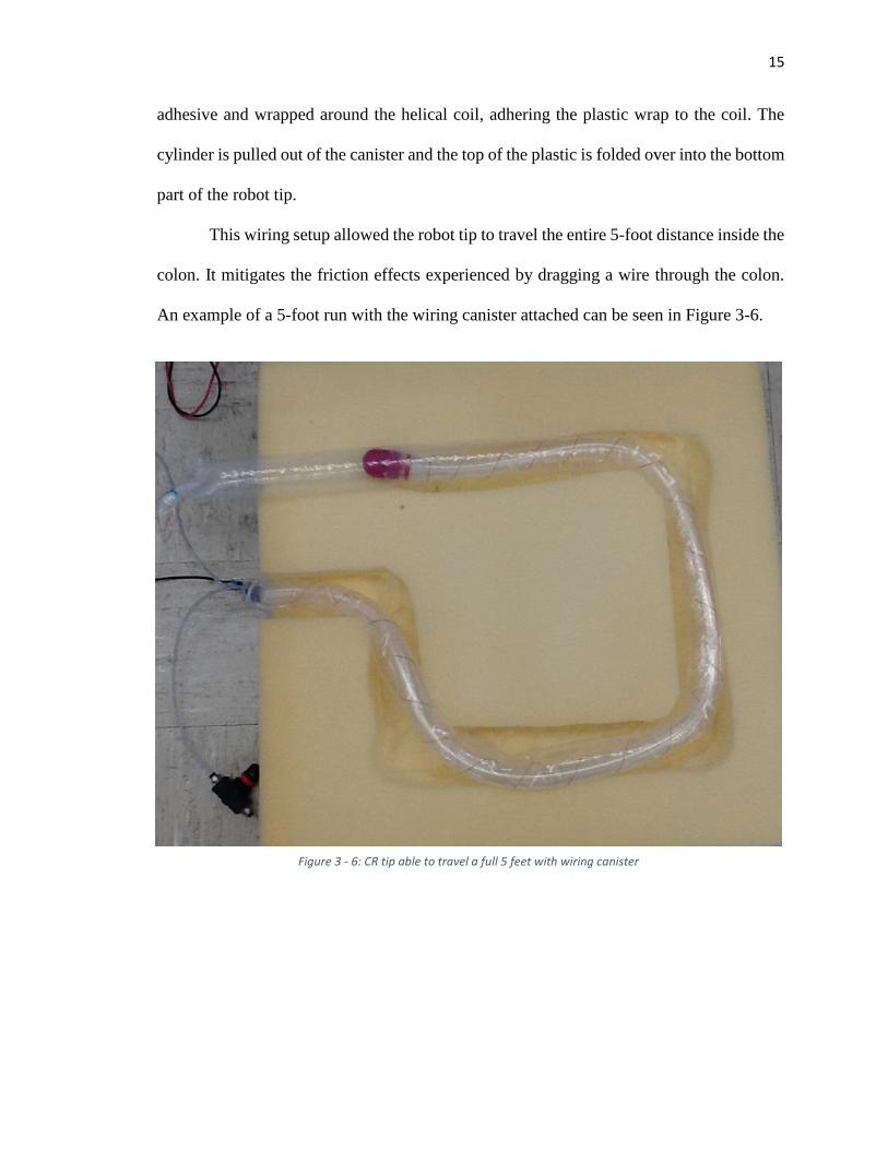
adhesive and wrapped around the helical coil, adhering the plastic wrap to the coil. The
cylinder is pulled out of the canister and the top of the plastic is folded over into the bottom
part of the robot tip.
This wiring setup allowed the robot tip to travel the entire 5-foot distance inside the
colon. It mitigates the friction effects experienced by dragging a wire through the colon.
An example of a 5-foot run with the wiring canister attached can be seen in Figure 3-6.
Figure 3 - 6: CR tip able to travel a full 5 feet with wiring canister
16
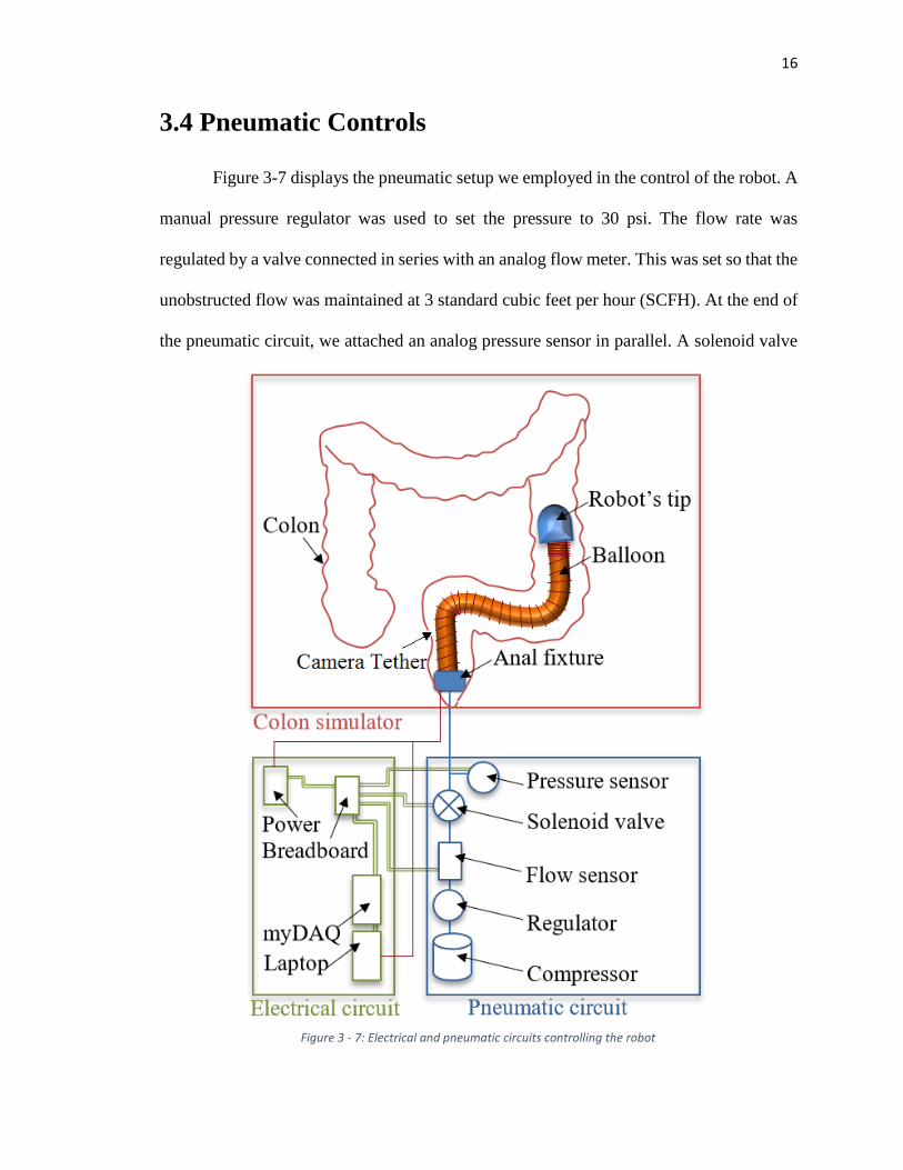
3.4 Pneumatic Controls
Figure 3-7 displays the pneumatic setup we employed in the control of the robot. A
manual pressure regulator was used to set the pressure to 30 psi. The flow rate was
regulated by a valve connected in series with an analog flow meter. This was set so that the
unobstructed flow was maintained at 3 standard cubic feet per hour (SCFH). At the end of
the pneumatic circuit, we attached an analog pressure sensor in parallel. A solenoid valve
Figure 3 - 7: Electrical and pneumatic circuits controlling the robot
17
and a switch were used to control the air flow. The switch operator controlled the
movement of the colonoscopy robot by watching the pressure sensor and switching off the
air flow when the pressure reached 17-20psi or greater (the bursting pressure discussed in
section 4.3).
3.5 Contributions
I contributed up to about 20% of the design of this device. My specific contributions
include the calculations for and change in the diameter of the robot tip in order to house
enough latex tubing; the snap- and twist-fit features for easy assembly; the camera housing
flanges in the robot tip; and the wire canister design and assembly methods. Many of the
other design choices, such as the initial concept, sealing mechanism, latex tubing
specifications, camera selection, and control system setup had previously been determined
by other students.
18
Chapter 4: Bench-Top Tests
Several tests were performed to verify the safety and efficacy of the colonoscopy
device. Testing was taken step-by-step from very basic tests of partial systems to a full-
system test inside an excised porcine colon.
4.1 Tubing Expansion Ratio
One of the most basic tests we ran was to determine the expansion ratio of the
surgical tubing used to inflate and move the robot. This test was performed by measuring
the uninflated tube length and then measuring the inflated length. The expansion ratio was
then calculated as:
𝐼𝑛𝑓𝑙𝑎𝑡𝑒𝑑 𝐿𝑒𝑛𝑔𝑡ℎ
𝑈𝑛𝑖𝑛𝑓𝑙𝑎𝑡𝑒𝑑 𝐿𝑒𝑛𝑔𝑡ℎ
The surgical tubing used had a linear expansion ratio of 3.6.
Since minimizing the diameter of the robot is important for the tip to fit inside the
rectum, the smallest length of surgical tubing that will still allow for travel through the
entire colon length (5 feet) is sought. A higher axial expansion ratio is desirable given the
same tube wall thickness and diameter. This would allow for an even smaller device. It
should be noted that the axial expansion is of primary importance in this device, while the
diametrical expansion is less important (a constraint rather than a target). In sizing the tube,
the only important thing to consider in the diameter is that the inflated tube diameter is less
than that of a colon; even then, the colon constrains the diametrical expansion of the tubing.
19
4.2 Heat Effects
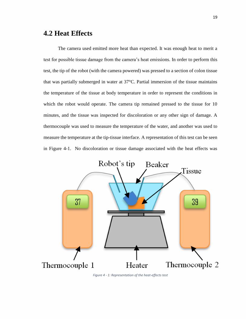
The camera used emitted more heat than expected. It was enough heat to merit a
test for possible tissue damage from the camera’s heat emissions. In order to perform this
test, the tip of the robot (with the camera powered) was pressed to a section of colon tissue
that was partially submerged in water at 37°C. Partial immersion of the tissue maintains
the temperature of the tissue at body temperature in order to represent the conditions in
which the robot would operate. The camera tip remained pressed to the tissue for 10
minutes, and the tissue was inspected for discoloration or any other sign of damage. A
thermocouple was used to measure the temperature of the water, and another was used to
measure the temperature at the tip-tissue interface. A representation of this test can be seen
in Figure 4-1. No discoloration or tissue damage associated with the heat effects was
Figure 4 - 1: Representation of the heat-effects test
20
observed, although in further development this should be explored in a histopathology
report.
4.3 Tube Burst Pressure
To determine the pressure at which the surgical tubing burst, a section of tubing
was filled with air, gradually increasing the air pressure until the balloon burst. The
corresponding pressure was recorded as 20psi. This presents a potential safety hazard in
the current state of the device. Although in most cases the robot can be operated under 15
psi, in a few instances, when the device was tested inside of excised colon tissue, the air-
filled balloon burst and ruptured the colon.
Researchers theorize that the use of water instead of air could be a potential solution
to this safety hazard. A simple test was performed to explore this theory: the latex tubing
was inflated with water and burst. The rupture of the water-filled balloon appeared much
less catastrophic than the air-filled balloon due to damping effects. This shows potential in
mitigating the damaging effects caused by balloon rupture inside the colon.
4.4 Device Benchtop Tests
In order to test the efficacy and functionality of the colonoscopy robot, several
benchtop tests were developed. Before testing the robot inside an actual colon, it was tested
via other methods.
4.4.1 Preliminary Testing
In preliminary testing, the colonoscopy robot was tested inside of a clear plastic
tube or unconstrained on a clean, hard surface (i.e. table or floor). This test verified that the
robot could traverse the 5-foot length required. It also allowed the researchers to adjust the
21
tension of the screws in the sealing mechanism until the latex tubing could be easily
dispensed.
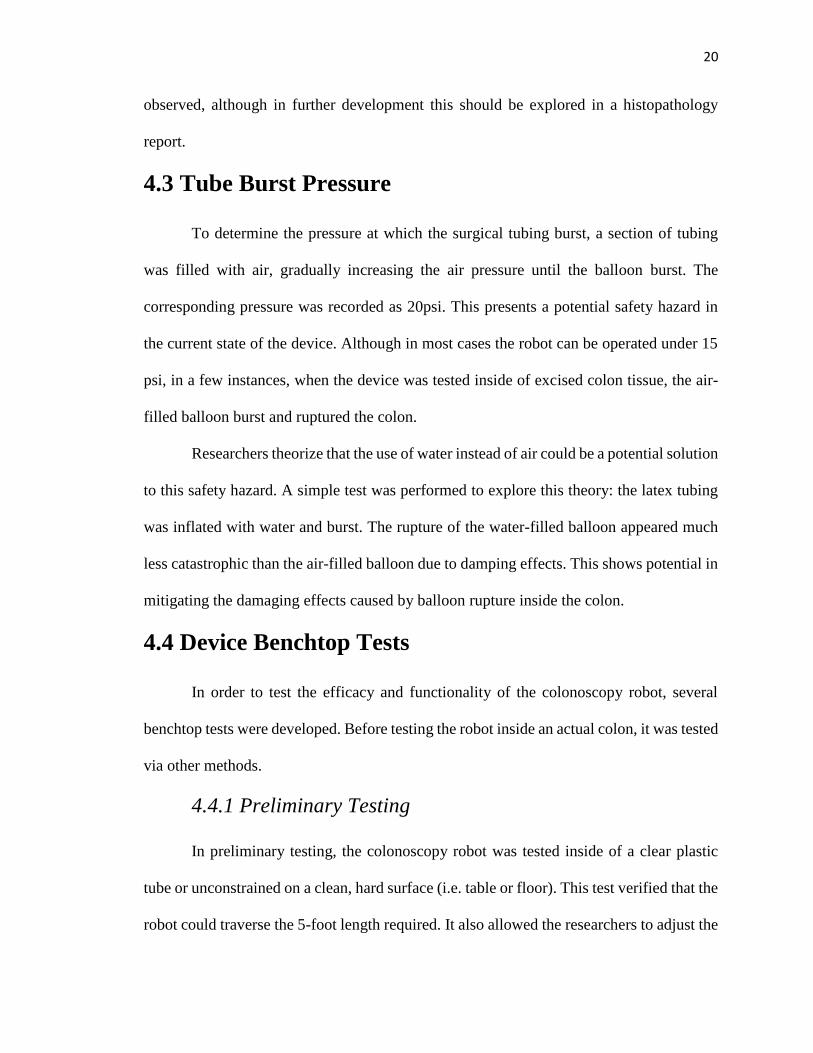
Another verification test was performed by testing the functionality of the
colonoscopy robot inside of an insufflated plastic sheath. This test configuration can be
seen in Figure 4-2. This test allowed the researchers to verify that the robot could travel
the entire 5-foot length and make turns successfully. Being in the clear sheath gives a clear
visual of the cable dispenser, allowing the researchers to verify the dispenser functionality
as well.
Figure 4 - 2: Benchtop test configuration. Robot was tested inside of a clear plastic sleeve.
22
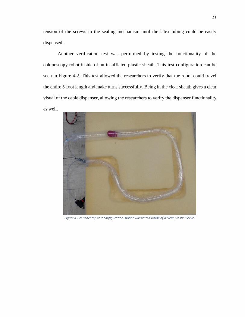
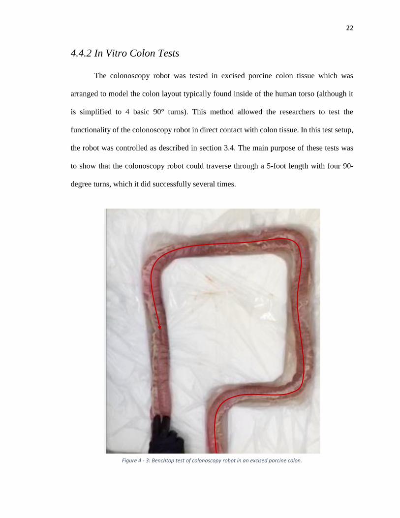
4.4.2 In Vitro Colon Tests
The colonoscopy robot was tested in excised porcine colon tissue which was
arranged to model the colon layout typically found inside of the human torso (although it
is simplified to 4 basic 90° turns). This method allowed the researchers to test the
functionality of the colonoscopy robot in direct contact with colon tissue. In this test setup,
the robot was controlled as described in section 3.4. The main purpose of these tests was
to show that the colonoscopy robot could traverse through a 5-foot length with four 90-
degree turns, which it did successfully several times.
Figure 4 - 3: Benchtop test of colonoscopy robot in an excised porcine colon.
23
4.5 Data Acquisition
In order to characterize the device further, sensors were placed in line with the
pneumatic controls to acquire the pressure and flow rate data. This data set was used by
researchers at the University of Nebraska at Omaha (UNO) to explore the capability of
rendering the colonoscopy robot navigation fully autonomous using artificial intelligence
methods.
4.5.1 LabVIEW Virtual Instrument
LabVIEW was the primary software used to obtain the signals from the sensors.
The raw signal was obtained with a National Instruments myDAQ data acquisition system
and filtered using a digital low-pass filter found in LabVIEW. The DAQ settings are shown
in appendix A-4-2.
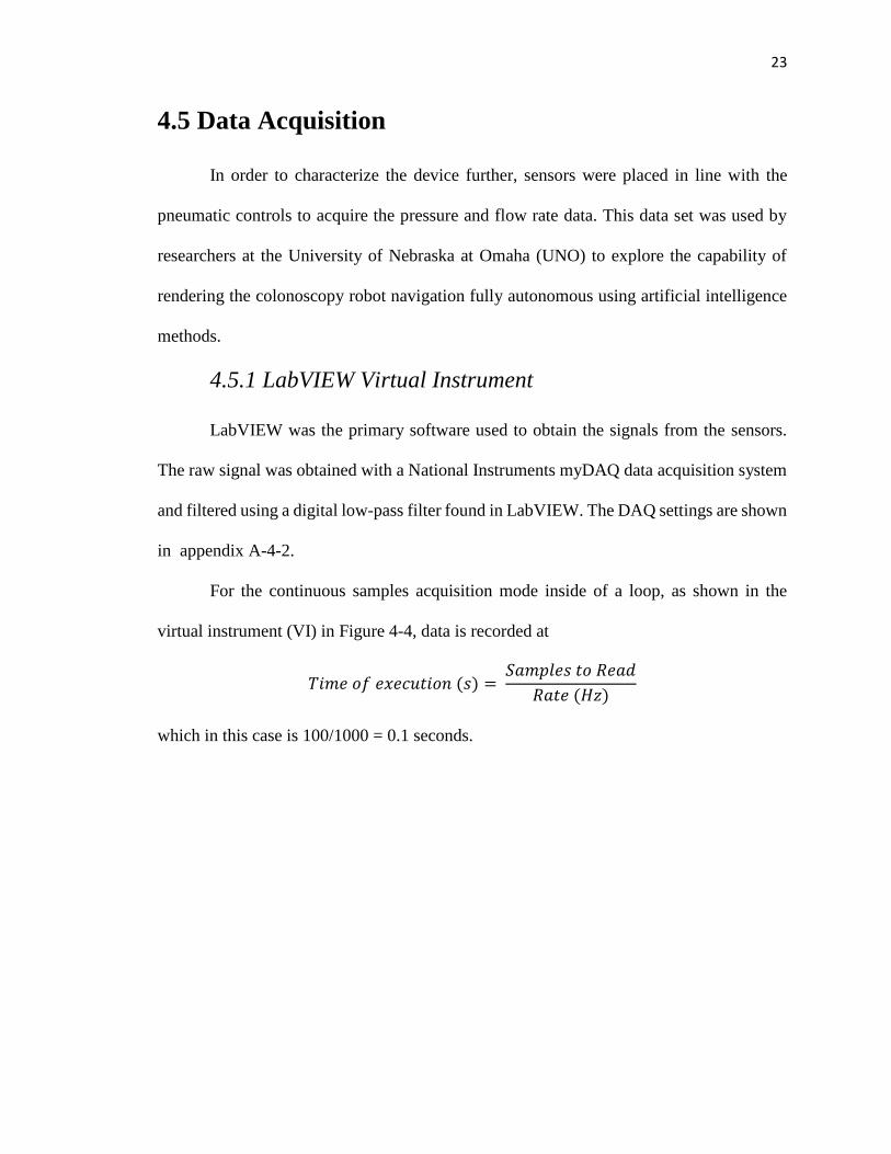
For the continuous samples acquisition mode inside of a loop, as shown in the
virtual instrument (VI) in Figure 4-4, data is recorded at
𝑇𝑖𝑚𝑒 𝑜𝑓 𝑒𝑥𝑒𝑐𝑢𝑡𝑖𝑜𝑛 (𝑠) = 𝑆𝑎𝑚𝑝𝑙𝑒𝑠 𝑡𝑜 𝑅𝑒𝑎𝑑
𝑅𝑎𝑡𝑒 (𝐻𝑧)
which in this case is 100/1000 = 0.1 seconds.
24
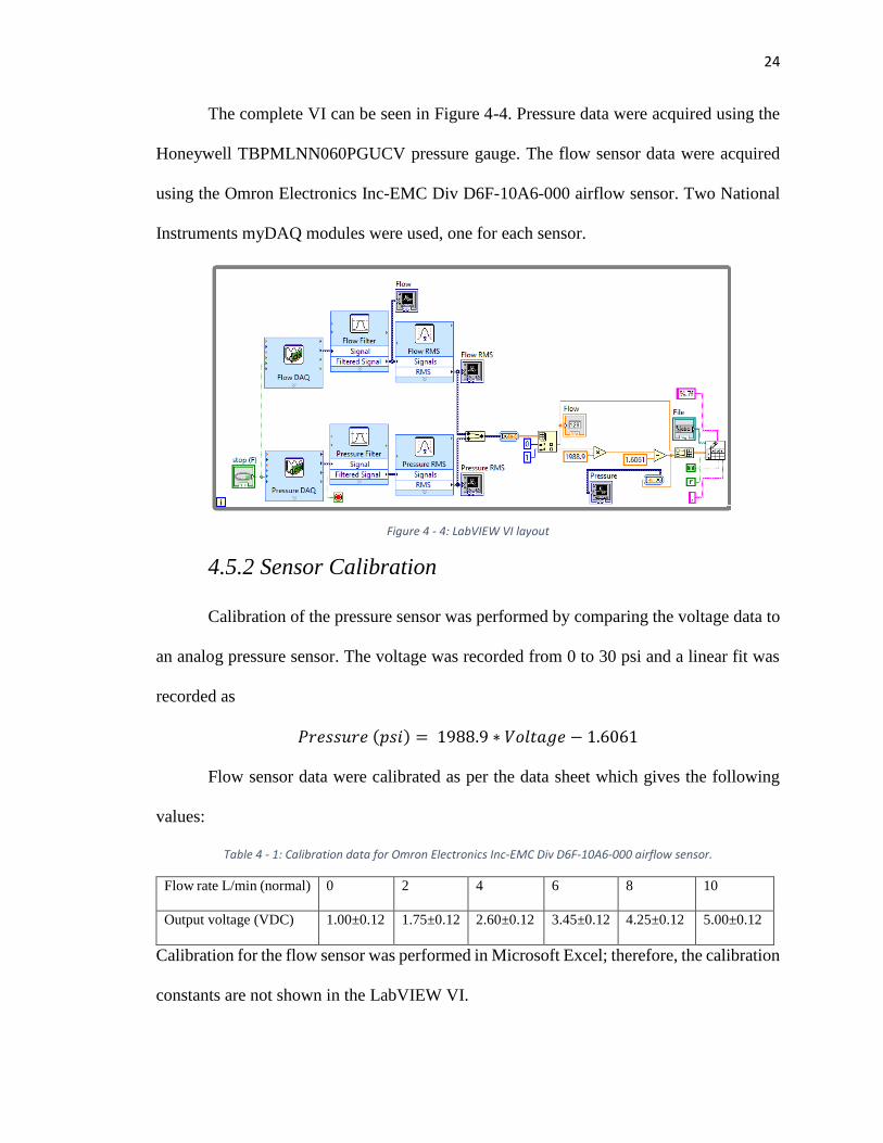
The complete VI can be seen in Figure 4-4. Pressure data were acquired using the
Honeywell TBPMLNN060PGUCV pressure gauge. The flow sensor data were acquired
using the Omron Electronics Inc-EMC Div D6F-10A6-000 airflow sensor. Two National
Instruments myDAQ modules were used, one for each sensor.
4.5.2 Sensor Calibration
Calibration of the pressure sensor was performed by comparing the voltage data to
an analog pressure sensor. The voltage was recorded from 0 to 30 psi and a linear fit was
recorded as
𝑃𝑟𝑒𝑠𝑠𝑢𝑟𝑒 (𝑝𝑠𝑖) = 1988.9 ∗ 𝑉𝑜𝑙𝑡𝑎𝑔𝑒 − 1.6061
Flow sensor data were calibrated as per the data sheet which gives the following
values:
Table 4 - 1: Calibration data for Omron Electronics Inc-EMC Div D6F-10A6-000 airflow sensor.
Flow rate L/min (normal) 0 2 4 6 8 10
Output voltage (VDC) 1.00±0.12 1.75±0.12 2.60±0.12 3.45±0.12 4.25±0.12 5.00±0.12
Calibration for the flow sensor was performed in Microsoft Excel; therefore, the calibration
constants are not shown in the LabVIEW VI.
Figure 4 - 4: LabVIEW VI layout
25
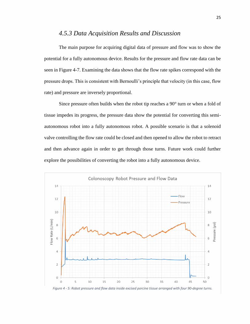
4.5.3 Data Acquisition Results and Discussion
The main purpose for acquiring digital data of pressure and flow was to show the
potential for a fully autonomous device. Results for the pressure and flow rate data can be
seen in Figure 4-7. Examining the data shows that the flow rate spikes correspond with the
pressure drops. This is consistent with Bernoulli’s principle that velocity (in this case, flow
rate) and pressure are inversely proportional.
Since pressure often builds when the robot tip reaches a 90° turn or when a fold of
tissue impedes its progress, the pressure data show the potential for converting this semi-
autonomous robot into a fully autonomous robot. A possible scenario is that a solenoid
valve controlling the flow rate could be closed and then opened to allow the robot to retract
and then advance again in order to get through those turns. Future work could further
explore the possibilities of converting the robot into a fully autonomous device.
Figure 4 - 5: Robot pressure and flow data inside excised porcine tissue arranged with four 90-degree turns.
26
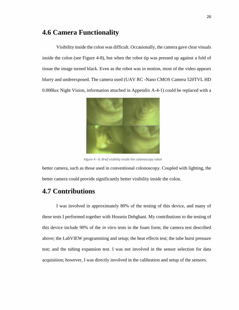
4.6 Camera Functionality
Visibility inside the colon was difficult. Occasionally, the camera gave clear visuals
inside the colon (see Figure 4-8), but when the robot tip was pressed up against a fold of
tissue the image turned black. Even as the robot was in motion, most of the video appears
blurry and underexposed. The camera used (UAV RC -Nano CMOS Camera 520TVL HD
0.008lux Night Vision, information attached in Appendix A-4-1) could be replaced with a
better camera, such as those used in conventional colonoscopy. Coupled with lighting, the
better camera could provide significantly better visibility inside the colon.
4.7 Contributions
I was involved in approximately 80% of the testing of this device, and many of
these tests I performed together with Hossein Dehghani. My contributions to the testing of
this device include 90% of the in vitro tests in the foam form; the camera test described
above; the LabVIEW programming and setup; the heat effects test; the tube burst pressure
test; and the tubing expansion test. I was not involved in the sensor selection for data
acquisition; however, I was directly involved in the calibration and setup of the sensors.
Figure 4 - 6: Brief visibility inside the colonoscopy robot
27
Part II: Biosensor Capsule
28
Chapter 5: Introduction and Motivation
Monitoring consumer health is becoming increasingly common via the new rise of
wearable technology and new research in implantable sensors. Such monitoring provides
a constant way to monitor health over a significant period of time. Several devices have
been created in recent years to monitor health and diagnose problems,including devices
that monitor heart rate, steps, caloric intake, glucose levels, and other biometrics [5-13][5-
14]. A few of the commonly used implants and wearables today include pacemakers [5-
15], continuous glucose monitoring devices [5-16], cochlear implants [5-17], pedometers
[5-20], and heart rate monitors [5-20]. These devices have typically been marketed and
sold to consumers; however, potential for wearable device use in surgery and post-
operation is also being discussed [5-18] [5-19].
While integrated biosensors monitor useful biometrics, they are often awkward in
appearance, bulky, or uncomfortable. Indeed, some people may not use wearable
technology because it is a constant reminder of health impairment or handicap. Implants
provide a means to conceal a diagnostic or monitoring device within the body while also
keeping the device close in proximity to the part of the body or organ of interest.
Implantable devices are also used for post-operation monitoring [5-21]. While implanting
conceals the device, most efforts to implant a sensor in vivo require invasive operations,
which may result in complications and scarring.
The device discussed in this section of the thesis is a sensor transport and
attachment device that offers non-invasive deep implantation of the sensor inside the
gastrointestinal tract (GI). The attachment method employed by the capsule is inspired by
29
the attachment mechanisms of lampreys and tapeworms using suction and “teeth” to latch
onto the mucosa inside the small bowel. This shows potential for successfully implanting
a sensor in the GI in a non-invasive way to successfully monitor various biometrics.
Part II of this thesis presents the details of the design of the biosensor capsule.
Various in vitro and in vivo tests are performed and presented to verify the efficacy and
safety of this device. While further work is needed to integrate a sensor onto the
mechanism, the device shows potential for accomplishing the task at hand: deep
implantation and successful attachment of a sensor plate.
Capsule endoscopy has been an effective method of diagnosis inside the small
bowel for over 15 years. This method involves swallowing a small capsule device which
contains an enclosed camera for diagnosis; passive motion of the capsule occurs through
intestinal peristalsis. Several studies have shown that capsule endoscopy is comparable and
even superior in some cases to ileocolonoscopy and small-bowel follow-through (SBFT)
in detecting small bowel disease, inflammatory lesions, obscure gastrointestinal bleeding,
polyposis syndromes, and suspected Crohn’s disease [5-1, 5-2, 5-3 ,5-4].
Recent research has focused on more active approaches in capsule endoscopy. In a
study by Kim et al., an earthworm-type device was developed to actively diagnose the
colon and small intestine [5-5]; however, the performance of this device was highly
influenced by the layout of the small intestine, making effective locomotion questionable.
In a study by Tognarelli et al., a stopping mechanism consisting of shape memory alloy
legs was developed to temporarily halt the passive motion of a capsule [5-6]. A capsule
driven from an external magnet source is another locomotion technique described in [5-7].
30
Despite the theoretical ability to actively diagnose the small bowel from the inside
with each of these devices, each technique is limited to just a few days of biometric
monitoring. Nevertheless, a capsule-like device proves to be an effective and non-invasive
method of transport for sensors and cameras inside the GI.
The new rise of wearable technology among consumers has shown the effectiveness
of long-term health monitoring, although such devices are often bulky or remind the user
of a health impairment. Implanting sensors inside the body for extended periods of time
conceals the sensor, mitigating feelings of embarrassment or a sense of handicap upon
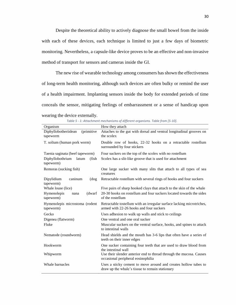
wearing the device externally. Table 5 - 1: Attachment mechanisms of different organisms. Table from [5-10].
Organism How they attach
Diphyllobotheriidean (primitive
tapeworm
Attaches to the gut with dorsal and ventral longitudinal grooves on
the scolex
T. solium (human pork worm) Double row of hooks, 22-32 hooks on a retractable rostellum
surrounded by four stickers
Taenia saginata (beef tapeworm) Four suckers on the top of the scolex with no rostellum
Diphyllobothrium latum (fish
tapeworm)
Scolex has a slit-like groove that is used for attachment
Remoras (sucking fish) One large sucker with many slits that attach to all types of sea
creatures
Dipylidium caninum (dog
tapeworm)
Retractable rostellum with several rings of hooks and four suckers
Whale louse (lice) Five pairs of sharp hooked clays that attach to the skin of the whale
Hymenolepis nana (dwarf
tapeworm)
20-30 hooks on rostellum and four suckers located towards the sides
of the rostellum
Hymenolepis microstoma (rodent
tapeworm)
Retractable tostellum with an irregular surface lacking microtriches,
armed with 22-26 hooks and four suckers
Gecko Uses adhesion to walk up walls and stick to ceilings
Digenea (flatworm) One ventral and one oral sucker
Fluke Muscular suckers on the ventral surface, hooks, and spines to attack
to intestinal walls
Nematode (roundworm) Head shields and the mouth has 3-6 lips that often have a series of
teeth on their inner edges
Hookworm One sucker containing four teeth that are used to draw blood from
the intestinal wall Whipworm Use their slender anterior end to thread through the mucosa. Causes
occasional peripheral eosinophilia
Whale barnacles Uses a sticky cement to move around and creates hollow tubes to
draw up the whale’s tissue to remain stationary
31
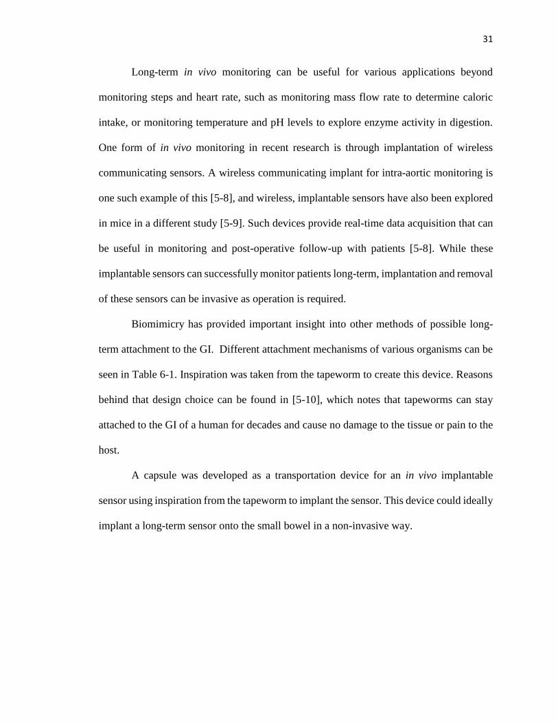
Long-term in vivo monitoring can be useful for various applications beyond
monitoring steps and heart rate, such as monitoring mass flow rate to determine caloric
intake, or monitoring temperature and pH levels to explore enzyme activity in digestion.
One form of in vivo monitoring in recent research is through implantation of wireless
communicating sensors. A wireless communicating implant for intra-aortic monitoring is
one such example of this [5-8], and wireless, implantable sensors have also been explored
in mice in a different study [5-9]. Such devices provide real-time data acquisition that can
be useful in monitoring and post-operative follow-up with patients [5-8]. While these
implantable sensors can successfully monitor patients long-term, implantation and removal
of these sensors can be invasive as operation is required.
Biomimicry has provided important insight into other methods of possible long-
term attachment to the GI. Different attachment mechanisms of various organisms can be
seen in Table 6-1. Inspiration was taken from the tapeworm to create this device. Reasons
behind that design choice can be found in [5-10], which notes that tapeworms can stay
attached to the GI of a human for decades and cause no damage to the tissue or pain to the
host.
A capsule was developed as a transportation device for an in vivo implantable
sensor using inspiration from the tapeworm to implant the sensor. This device could ideally
implant a long-term sensor onto the small bowel in a non-invasive way.
32
Chapter 6: Capsule Design
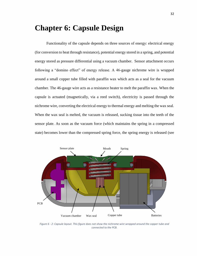
Functionality of the capsule depends on three sources of energy: electrical energy
(for conversion to heat through resistance), potential energy stored in a spring, and potential
energy stored as pressure differential using a vacuum chamber. Sensor attachment occurs
following a “domino effect” of energy release. A 46-gauge nichrome wire is wrapped
around a small copper tube filled with paraffin wax which acts as a seal for the vacuum
chamber. The 46-gauge wire acts as a resistance heater to melt the paraffin wax. When the
capsule is actuated (magnetically, via a reed switch), electricity is passed through the
nichrome wire, converting the electrical energy to thermal energy and melting the wax seal.
When the wax seal is melted, the vacuum is released, sucking tissue into the teeth of the
sensor plate. As soon as the vacuum force (which maintains the spring in a compressed
state) becomes lower than the compressed spring force, the spring energy is released (see
Batteries Copper tube Wax seal Vacuum chamber
PCB
Sensor plate Mouth Spring
Figure 6 - 2: Capsule layout. This figure does not show the nichrome wire wrapped around the copper tube and connected to the PCB.
33
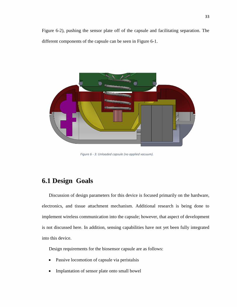
Figure 6-2), pushing the sensor plate off of the capsule and facilitating separation. The
different components of the capsule can be seen in Figure 6-1.
6.1 Design Goals
Discussion of design parameters for this device is focused primarily on the hardware,
electronics, and tissue attachment mechanism. Additional research is being done to
implement wireless communication into the capsule; however, that aspect of development
is not discussed here. In addition, sensing capabilities have not yet been fully integrated
into this device.
Design requirements for the biosensor capsule are as follows:
Passive locomotion of capsule via peristalsis
Implantation of sensor plate onto small bowel
Figure 6 - 3: Unloaded capsule (no applied vacuum).
34
Separation of capsule from sensor plate following attachment
Minimal damage to attached tissue
Long-term attachment up to 14 days is desired
Preliminary design of the tissue attachment mechanism is discussed in [5-10] and [6-1];
these two articles discuss the test methods used to determine the sensor plate attachment
mechanism and the results of long-term adhesion. Design regarding the geometry of the
capsule, circuit board, sensor plate o-rings, and vacuum chamber are discussed here.
6.2 Capsule Geometry
Capsules used in endoscopy vary in size. In 2000, Given Imaging developed a
capsule that was 11mm in diameter and 30mm long [5-11]. The OdoCapsule, designed to
stabilize images inside the bowel and provide capsule tracking data, was designed with
dimensions of 13mm x 30mm [5-12].
In this design, the diameter and length of the capsule are highly influenced by the
size of the components used inside. The battery diameter, specifically, is the predominant
constraint, as smaller batteries could allow a smaller capsule diameter. The vacuum
chamber volume is another constraint that influences both diameter and length of the
capsule. Due to the size of the batteries and the vacuum volume, the dimensions of the
capsule are 13mm x 37.5mm. Further work can be done to shrink the size of the capsule;
35
however, the larger size provided more flexibility in testing different vacuum volumes and
changing components without having to redesign the capsule.
Figure 6 - 3: Capsule circuit diagram
36
6.3 Electronics and PCB
A circuit schematic for the electronics used in the capsule can be seen in Figure 6-
3, and the circuit board layout can be seen in Figure 6-4. A PIC microcontroller
(PIC10F322) is used to control current flow through the nichrome wire. Once the reed
switch is activated (by close proximity to a magnet), the microcontroller sends current
through the LED, causing it to blink. After the blinking stops, the microcontroller sends
voltage through the pin connected to the base pin on the transistor, allowing current to flow
through the nichrome wire. The script used to program the microcontroller can be found in
Appendix A-6-1.
Figure 6 - 4: Capsule PCB layout. R1 = 1k Ohms and R2 = 10k Ohms
37
6.4 Wax Valve and Nichrome Wire
The wax valve is a key element in this design. Reliability of the wax is essential.
Paraffin wax (Gulfwax, 203-045-005) mixed with stearic acid is used to fill a short copper
tube that is 3mm long and 2.49mm in diameter. A 9:1 ratio of wax to stearic acid proved
sufficient to keep the solution at a melting point just above body temperature.
A 46-gauge nichrome wire was wrapped around the copper tube and used as a
heating element (see Figure 6-5). When a reed switch on the circuit board is actuated, the
microcontroller switches the pin that is connected to the transistor to a high state, enabling
current flow through the transistor. Essentially, when current flow is enabled through the
transistor, the entire energy supply is sent through the nichrome wire, heating up the copper
tube. Current flow only ends once the batteries are completely drained or the batteries are
removed and reinserted.
Figure 6 - 5: Nichrome wire wrapped around copper tube in preliminary assembly stages.
38
Power transfer through the nichrome wire can be calculated as
𝑃 = 𝑉𝐼 (1)
and the current, 𝐼, can be calculated using Ohm’s law as
𝐼 =𝑉
𝑟+𝑅 (2)
where 𝑟 is the internal resistance and 𝑅 is the resistance of the nichrome wire. Substituting
this into the power equation results in
𝑃 = 𝑉2
𝑟+𝑅 (3)
Breaking this up into power dissipated by both internal resistance and the nichrome wire
results in
𝑃𝑟 = 𝐼2𝑟 = 𝑉2𝑟
(𝑟+𝑅)2 (4)
and
𝑃𝑅 = 𝐼2𝑅 = 𝑉2𝑅
(𝑟+𝑅)2 (5)
respectively. Note that total power, 𝑃𝑡, is as follows:
𝑃𝑡 = 𝑃𝑟 + 𝑃𝑅 (6)
Therefore, some of the power is dissipated in the internal resistance of the battery while
the rest is dissipated in the nichrome wire. Let 𝑥 = 𝑅/𝑟, and 𝑦 =𝑃𝑅
𝑉2
𝑟
; from equation (5),
it follows that
𝑦 = 𝑥
(1+𝑥)2 (7)
The maximum value of equation (7) occurs when 𝑥 = 1, which results in 𝑦 = 1/4. Thus,
since internal resistance and voltage are constants, varying the nichrome resistance results
in maximum power transfer when the nichrome wire resistance is equal to the internal
39
resistance. This makes sense in that if the internal resistance is greater than the load, most
of the power is dissipated internally, and if the load is greater than the resistance, current
is reduced.
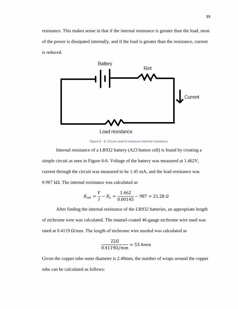
Internal resistance of a LR932 battery (A23 button cell) is found by creating a
simple circuit as seen in Figure 6-6. Voltage of the battery was measured at 1.462V,
current through the circuit was measured to be 1.45 mA, and the load resistance was
0.987 kΩ. The internal resistance was calculated as
𝑅𝑖𝑛𝑡 =𝑉
𝐼− 𝑅𝐿 =
1.462
0.00145− 987 = 21.28 𝛺
After finding the internal resistance of the LR932 batteries, an appropriate length
of nichrome wire was calculated. The enamel-coated 46-gauge nichrome wire used was
rated at 0.4119 Ω/mm. The length of nichrome wire needed was calculated as
22𝛺
0.4119Ω/mm= 53.4𝑚𝑚
Given the copper tube outer diameter is 2.49mm, the number of wraps around the copper
tube can be calculated as follows:
Figure 6 - 6: Circuit used to measure internal resistance.
40
# 𝑤𝑟𝑎𝑝𝑠 =53.4𝑚𝑚
𝜋 ∗ 2.49𝑚𝑚= 6.83 𝑤𝑟𝑎𝑝
Heating of the wire is not overly sensitive to different lengths at such a small scale;
therefore, 8 wraps has been used to maximize the surface area of the nichrome on the
copper tube. The tail ends of the nichrome soldered to the copper tubes as shown in
Figure 6-4 add a little extra length as well, and the typical resistance reading as measured
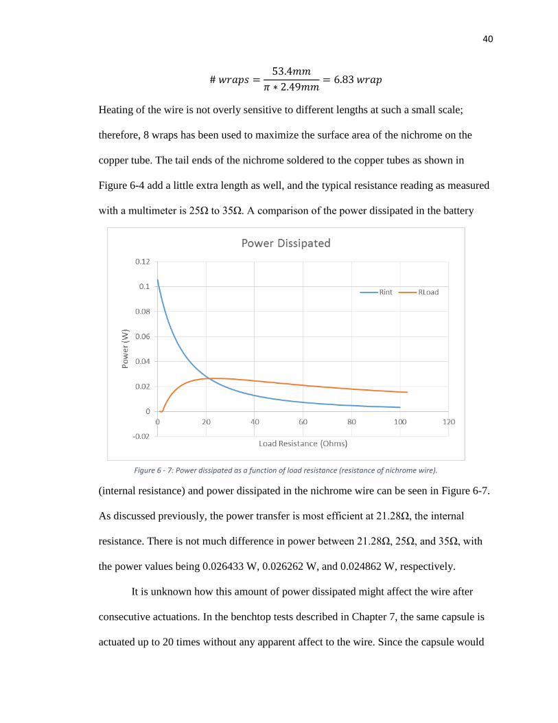
with a multimeter is 25Ω to 35Ω. A comparison of the power dissipated in the battery
(internal resistance) and power dissipated in the nichrome wire can be seen in Figure 6-7.
As discussed previously, the power transfer is most efficient at 21.28Ω, the internal
resistance. There is not much difference in power between 21.28Ω, 25Ω, and 35Ω, with
the power values being 0.026433 W, 0.026262 W, and 0.024862 W, respectively.
It is unknown how this amount of power dissipated might affect the wire after
consecutive actuations. In the benchtop tests described in Chapter 7, the same capsule is
actuated up to 20 times without any apparent affect to the wire. Since the capsule would
Figure 6 - 7: Power dissipated as a function of load resistance (resistance of nichrome wire).
41
likely only be needed for one actuation, it can be assumed that the nichrome wire of this
length is sufficient for this device.
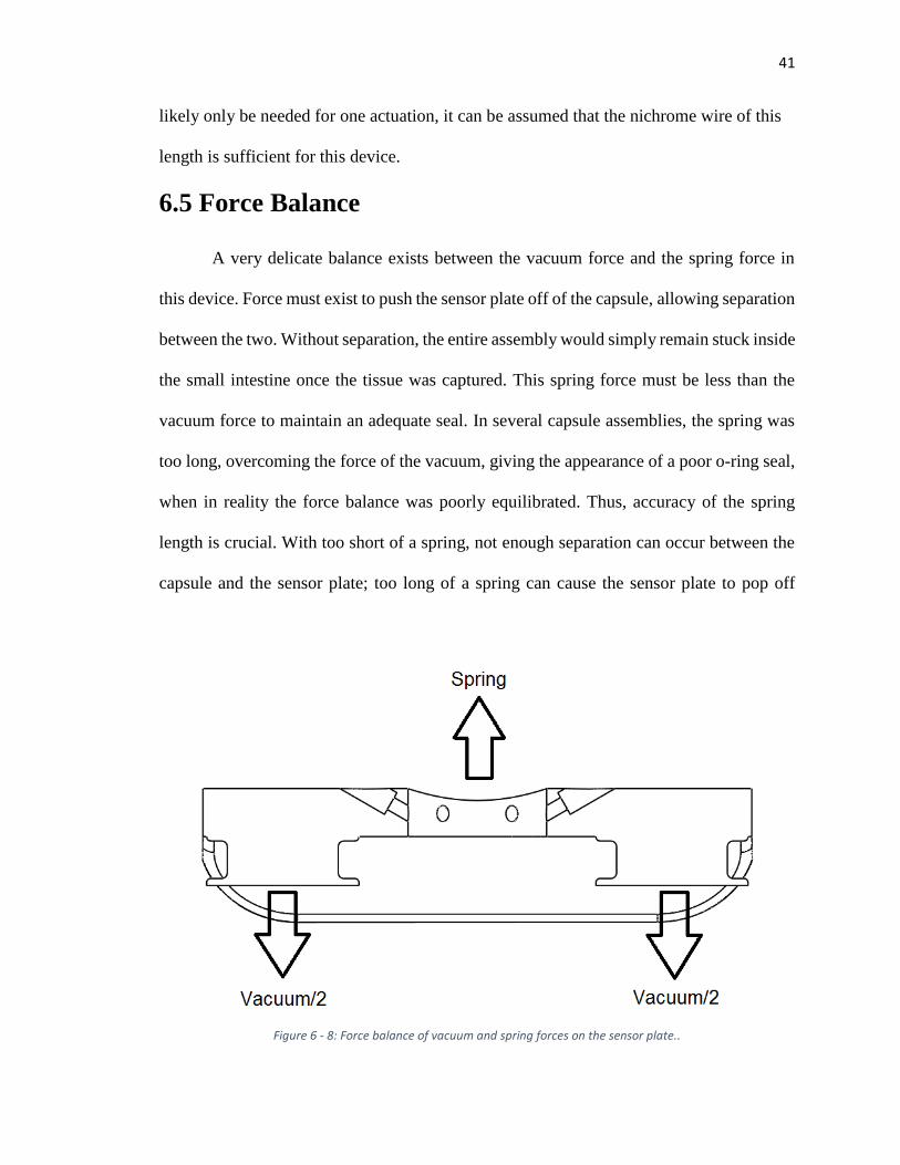
6.5 Force Balance
A very delicate balance exists between the vacuum force and the spring force in
this device. Force must exist to push the sensor plate off of the capsule, allowing separation
between the two. Without separation, the entire assembly would simply remain stuck inside
the small intestine once the tissue was captured. This spring force must be less than the
vacuum force to maintain an adequate seal. In several capsule assemblies, the spring was
too long, overcoming the force of the vacuum, giving the appearance of a poor o-ring seal,
when in reality the force balance was poorly equilibrated. Thus, accuracy of the spring
length is crucial. With too short of a spring, not enough separation can occur between the
capsule and the sensor plate; too long of a spring can cause the sensor plate to pop off
Figure 6 - 8: Force balance of vacuum and spring forces on the sensor plate..
42
despite a good vacuum seal. The force balance is represented in Figure 6-8. Force of the
spring can be calculated as
𝐹𝑠 = 𝑘𝑥,
where 𝑘 is the spring constant and 𝑥 is the spring deflection. Force of the vacuum can be
calculated as
𝐹𝑉 = 𝑃 ∗ 𝐴𝑡𝑜𝑡,
where 𝑃 is the pressure difference felt by the vacuum, and 𝐴𝑡𝑜𝑡 is the combined area of
the holes in the capsule where the sensor plate seals. Naturally, 𝐹𝑉 needs to be greater
than 𝐹𝑠 for the sensor plate to remain sealed to the capsule. Therefore, since
𝐹𝑉 > 𝐹𝑠,
it follows that
𝑥 <𝑃 ∗ 𝐴𝑡𝑜𝑡
𝑘
Vacuum pressure of 13.76 psi can be consistently achieved in the current vacuum system.
The diameter of the seal location in the capsule is measured to be 0.218in. The total area
is calculated as
𝐴𝑡𝑜𝑡 = 2 ∗ 𝜋 ∗0.2182
4= 0.07465 𝑖𝑛2
The spring stiffness value from the vendor (McMaster-Carr product number 94125K521)
is 0.41 lbs/mm (or 10.414 lbs/in). Thus,
𝑥 <13.76 ∗ 0.07465
10.414
with a calculated value of
𝑥 < 0.0986𝑖𝑛
43
Since the well in which the spring sits is 0.171 inches deep, the total length of the spring
theoretically should not exceed 0.27 inches (0.717in + 0.0986in = 0.27in). This calculated
length was tested by iteratively cutting down the spring until the capsule sealed
repeatedly for a long period of time. The capsule was able to seal reliably at a spring
length of 0.296”, and it could remain sealed with this spring length for longer than 5
days.
6.6 O-rings
Two o-rings are used to seal the sensor plate to the capsule. The o-ring seal locations
can be seen in Figure 6-8. Sealing surfaces are not often 3D printed; however, in order to
save money manufacturing the capsule tops, the parts were 3D printed. For this design a
Stratasys Objet 30 3D printer (28 micron resolution) was used to print the capsule parts.
The glossy surface finish feature gave a better sealing surface than the matte finish.
To account for the ridges due to the layers in the print direction (same direction as
the axis of the seal cylinders), a low durometer (50A) buna o-ring was used. Since relatively
low pressure is experience by the capsule, a low-durometer material would be sufficient,
and the flexibility of the rubber at low hardness would allow it to seal against a rougher
surface.
O-ring dimensions were designed following the 26th edition Machinery’s
Handbook [6-2].
6.7 Vacuum Chamber
In theory, maximizing the vacuum chamber volume inside the capsule is ideal since
maximum volume results in maximum mass flow into the chamber. This ensures that
44
sufficient tissue is sucked into the sensor plate needles. In reality, more than just tissue is
sucked into the vacuum chamber. Whatever is inside the well of the capsule top will be
sucked through the copper tube as well as other things inside the intestine. For this reason,
administering the capsule to the patient in the future would likely follow a period of fasting.
Two different vacuum volumes were used to test this theory, and corresponding test
methods can be found in Chapter 7. The maximum volume achieved in the design of the
vacuum volume was 0.35 cm3 which was the vacuum volume used in most of the tests
described in Chapter 7.
6.8 Contributions
I commenced my work in this project with most of the initial design determined.
My significant contribution to the design of this capsule is the calculated spring length; the
seal geometry; the test and assembly fixtures; and the o-ring durometer specification.
Everything else with respect to the design was previously determined including the wax to
stearic acid ratio; the circuit board layout and design; the microcontroller code; the
nichrome wire calculations; the vacuum volume geometry; the sensor plate geometry; the
battery internal resistance calculations; and other related design choices. The majority of
my contributions with this project can be found in the testing sections of Chapter 7.
45
Chapter 7: Capsule Testing
Several tests were devised to test the functionality and safety of the capsule. Other
tests were created to test the functionality of certain components or to find the best
combination of variables to use in the capsule (e.g., vacuum volume). After mixed results
in some of the in vivo tests, further testing was done to test for significance of variables
such as mucus filling the capsule top well, for example. Each of these tests is described in
detail in this chapter.
7.1 Wax Melting Point
Care was taken to ensure that the melting point of the wax was not too close to body
temperature. Should this happen, the vacuum could be released prematurely, resulting in
attachment of the sensor plate to an undesirable location inside the body.
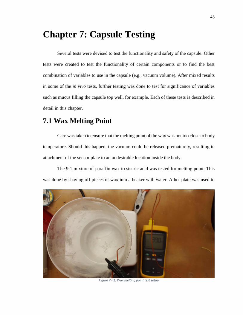
The 9:1 mixture of paraffin wax to stearic acid was tested for melting point. This
was done by shaving off pieces of wax into a beaker with water. A hot plate was used to
Figure 7 - 1: Wax melting point test setup
46
heat the water in the beaker incrementally until the wax began to melt. Melting was
inspected visually as the changes in the shape of the wax particles. Temperature of the
water inside the beaker was measured at the surface (or location of the wax) with a
thermocouple. Melting point of the wax was determined to be between 40° and 45° C. The
setup for this test can be seen in Figure 7-1.
In addition to this test, another test was performed where the sealed capsules were
brought up to body temperature in a temperature controlled chamber. Again, a
thermocouple was placed at the height of the capsules inside the chamber. Out of five
capsules, none of the wax seals failed in this experiment; wax seal failure would be visible
if the sensor plate popped off the capsule.
7.2 Capsule Seal Tests
There are various ways to test the capsule’s vacuum seal capability. The simplest
and most straightforward method is to seal it in the vacuum chamber and observe that it is
sealed (meaning the sensor plate does not pop off the capsule and the spring remains
compressed). If the capsule has a leak somewhere, the spring will be able to easily push
the sensor plate off of the capsule.
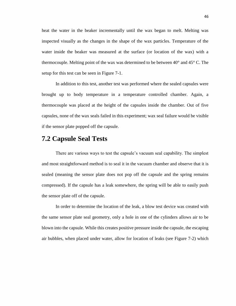
In order to determine the location of the leak, a blow test device was created with
the same sensor plate seal geometry, only a hole in one of the cylinders allows air to be
blown into the capsule. While this creates positive pressure inside the capsule, the escaping
air bubbles, when placed under water, allow for location of leaks (see Figure 7-2) which
47
are then covered with vacuum grease or UV glue. If the leak is located in the battery
compartment, vacuum grease is typically used since the hardened UV glue would often
cause the batteries to fit poorly inside. A leak anywhere on the body of the capsule (outside
of the battery compartment) would be repaired with UV glue, a more permanent fix. The
blow test device is an effective method for locating leaks; however, it is limited to locating
leaks in the capsule body and battery compartment only—leaks around the copper tube and
o-rings are still difficult to identify with this device.
A third method for testing is attaching the blow test device to the vacuum and
applying negative pressure to the capsule. Using the blow test device instead of the vacuum
chamber ensures that the sensor plate seal geometry is adequately seated, and negative
pressure is directly applied to the capsule. If the blow test device pops off too quickly (with
Figure 7 - 2: Blow test device
48
a spring underneath), or negative pressure loss is too rapid (without a spring), a leak is
likely.
If a leak is still suspected after testing with these three methods, it is recommended
to fill the battery compartment with vacuum grease and retest the seal. If the sensor plate
still fails to seal, a dot of UV glue can be cured on top of the copper tube, and the device
can be retested; this UV glue dot can be easily removed with a pair of tweezers after testing.
7.3 Seal Geometry Tests
A test was devised to determine adequate seal geometry. This was done by creating
a fixture with the same geometry as the capsule top seal cylinder (Figure 7-3) and several
plugs representing the sensor plate seal geometry (Figure 7-4). In some instances the o-
Figure 7 - 3: Seal geometry test fixture
49
ring was compressed between two surfaces (plug C in Figure 7-4) and in others it was in
an o-ring groove (plug 2 in Figure 7-4).
The seal geometry test fixture was bolted to a rigid surface and the plugs were
pulled with the tensile tester after being vacuum sealed. It was determined that a groove
for the o-ring, as per the dimensions outlined in the Machinery’s Handbook [7-2], had the
strongest seal.
7.4 In Vitro Tests
Different in vitro tests were run to determine the reliability and functionality of the
capsule. They were also used to determine the best variables to use in the test. In both in
vitro and in vivo tests, the porcine model was healthy and roughly 70kg in weight.
7.4.1 Vacuum volume and added mucus
An in vitro test was performed to determine what volume of vacuum could reliably
attach the sensor plate to the small intestine. The test was performed within 36 hours of
euthanizing the pig to ensure that fresh tissue was being used, and the tissue used was
immediately immersed in saline and remained immersed throughout the test. In this test a
Figure 7 - 4: Plugs representing sensor plate seal geometry
50
0.25cc volume was compared to a 0.35cc volume.
Theoretically, the larger volume should be more
reliable as it allows for a larger mass flow; thus
more tissue can likely be sucked into the teeth of
the sensor plate.
The test was performed by inserting the
capsule into a 3”-4” section of small intestine and
magnetically actuating it. A string connected the
sensor plate to a tensile testing machine (Figure 7-
5) and the peak force of the sensor plate
attachment was recorded. Results for both vacuum
volumes can be seen in Table 7-1.
A major question to answer was if mucus
inside the small intestine affected the ability of the capsule to suck in tissue. This was tested
as well in both the 0.35cc capsule and the 0.25cc capsule by squeezing mucus out of the
intestine and manually inserting it into the mouth of the sensor plate (Figure 7-6). Results
for the attachment strength with mucus inserted into the capsule can also be seen in Table
7-1.
Figure 7 - 5: In vitro attachment force test
Test No. 0.25cc 0.25cc+mucus 0.35cc 0.35cc+mucus
1 2.221 1.733 3.802 1.985
2 6.645 4.492 4.694 7.554
3 1.464 6.931 3.600 9.354
Mean 3.443 4.385 4.032 6.298
SD 2.798 2.601 0.582 3.842
Attachment Strength (Newtons)
Table 7 - 1: Attachment strength vs. vacuum volume and mucus addition
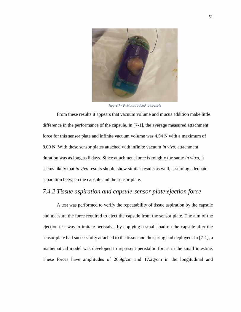
51
From these results it appears that vacuum volume and mucus addition make little
difference in the performance of the capsule. In [7-1], the average measured attachment
force for this sensor plate and infinite vacuum volume was 4.54 N with a maximum of
8.09 N. With these sensor plates attached with infinite vacuum in vivo, attachment
duration was as long as 6 days. Since attachment force is roughly the same in vitro, it
seems likely that in vivo results should show similar results as well, assuming adequate
separation between the capsule and the sensor plate.
7.4.2 Tissue aspiration and capsule-sensor plate ejection force
A test was performed to verify the repeatability of tissue aspiration by the capsule
and measure the force required to eject the capsule from the sensor plate. The aim of the
ejection test was to imitate peristalsis by applying a small load on the capsule after the
sensor plate had successfully attached to the tissue and the spring had deployed. In [7-1], a
mathematical model was developed to represent peristaltic forces in the small intestine.
These forces have amplitudes of 26.9g/cm and 17.2g/cm in the longitudinal and
Figure 7 - 6: Mucus added to capsule

52
circumferential directions, respectively. For our capsule, the maximum forces are 126.8gf
in the longitudinal direction and 64.5gf in the circumferential direction.
After actuating the capsule, observed tissue suction (see Figure 7-8) was recorded.
Those capsules that successfully aspirated tissue were then attached to the tensile testing
Figure 7 - 10: Sensor plate ejection test
Figure 7 - 7: Succesful tissue aspiration
Figure 7 - 8: Sensor plate ejection testFigure 7 - 9: Succesful tissue aspiration
53
machine with a string to test for ejection force (see Figure 7-8). Separation of the sensor
plate from the capsule due to the spring typically occurred unaided; however, in a few
instances, this separation did not occur until the capsule was pulled with the tensile testing
machine. For capsule loading, a constant load of 50 gf was applied for one minute, after
which the load was ramped up to 500 gf and the maximum force of ejection was recorded.
The test was repeated 14 times, and tissue aspiration was 100% successful. Of the
14 successful aspirations, 12 successfully captured the tissue (85.71%). The sensor plate
was ejected successfully 11 of the 12 times (91.67%). The average force required to
successfully eject the sensor plate from the capsule was 67.7±60.8 gf. Half of these
capsules separated with less than 60 gf.
7.5 In Vivo Tests
Three in vivo tests were performed to test the functionality and reliability of the
capsule inside the body. In all three tests, a porcine model was used—each about 70kg in
weight. Each test provided valuable information for the development of the capsule.
7.5.1 In vivo test November 19th, 2015
Procedures for this test were outlined as follows:
1.) Pick a 70kg crossbred, neutered, domestic pig; confirm the animal health status.
Animals will be acclimated in the LScA facility for 5 days prior to any procedures
2.) Set up the bench-top X-ray machine.
3.) Prior to surgery the pig will be fasted for 12 hours.
4.) Anesthesia will be accomplished by an intramuscular injection of ketamine,
xylazine and telazol and will be maintained on isoflurane.
5.) An abdominal laparotomy will be performed to expose a section of the duodenum.
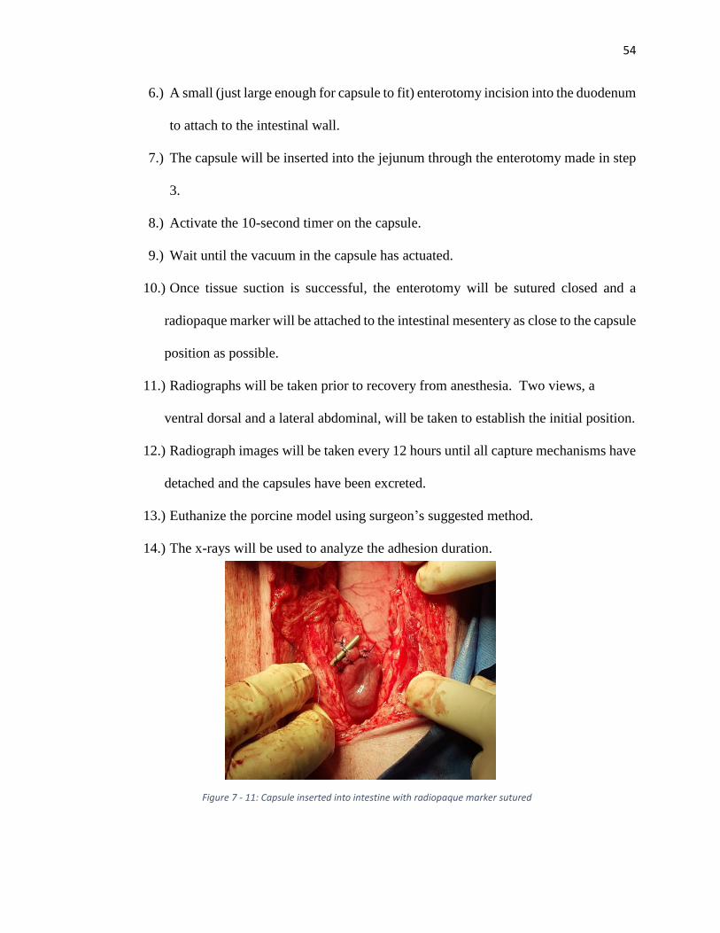
54
6.) A small (just large enough for capsule to fit) enterotomy incision into the duodenum
to attach to the intestinal wall.
7.) The capsule will be inserted into the jejunum through the enterotomy made in step
3.
8.) Activate the 10-second timer on the capsule.
9.) Wait until the vacuum in the capsule has actuated.
10.) Once tissue suction is successful, the enterotomy will be sutured closed and a
radiopaque marker will be attached to the intestinal mesentery as close to the capsule
position as possible.
11.) Radiographs will be taken prior to recovery from anesthesia. Two views, a
ventral dorsal and a lateral abdominal, will be taken to establish the initial position.
12.) Radiograph images will be taken every 12 hours until all capture mechanisms have
detached and the capsules have been excreted.
13.) Euthanize the porcine model using surgeon’s suggested method.
14.) The x-rays will be used to analyze the adhesion duration.
Figure 7 - 11: Capsule inserted into intestine with radiopaque marker sutured
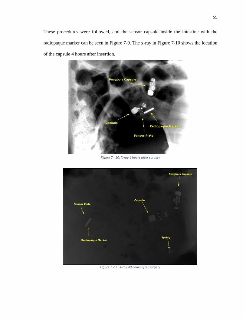
55
These procedures were followed, and the sensor capsule inside the intestine with the
radiopaque marker can be seen in Figure 7-9. The x-ray in Figure 7-10 shows the location
of the capsule 4 hours after insertion.
Figure 7 - 10: X-ray 4 hours after surgery
Figure 7 - 12: X-ray 52 hours after surgeryFigure 7 - 10: X-ray 4 hours after surgery
Figure 7 -11: X-ray 40 hours after surgery
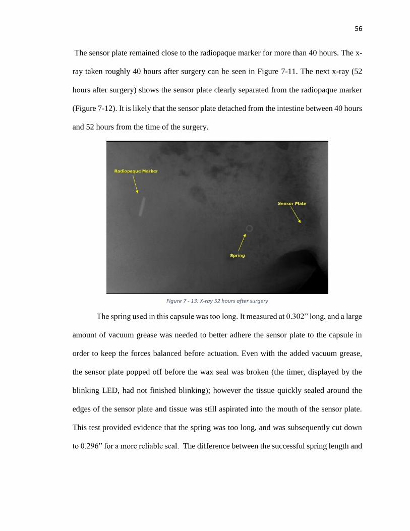
56
The sensor plate remained close to the radiopaque marker for more than 40 hours. The x-
ray taken roughly 40 hours after surgery can be seen in Figure 7-11. The next x-ray (52
hours after surgery) shows the sensor plate clearly separated from the radiopaque marker
(Figure 7-12). It is likely that the sensor plate detached from the intestine between 40 hours
and 52 hours from the time of the surgery.
The spring used in this capsule was too long. It measured at 0.302” long, and a large
amount of vacuum grease was needed to better adhere the sensor plate to the capsule in
order to keep the forces balanced before actuation. Even with the added vacuum grease,
the sensor plate popped off before the wax seal was broken (the timer, displayed by the
blinking LED, had not finished blinking); however the tissue quickly sealed around the
edges of the sensor plate and tissue was still aspirated into the mouth of the sensor plate.
This test provided evidence that the spring was too long, and was subsequently cut down
to 0.296” for a more reliable seal. The difference between the successful spring length and
Figure 7 - 13: X-ray 52 hours after surgery
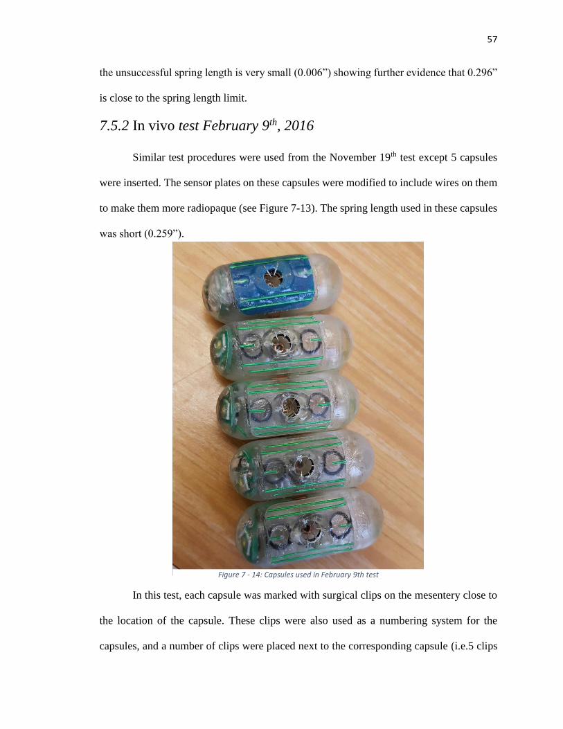
57
the unsuccessful spring length is very small (0.006”) showing further evidence that 0.296”
is close to the spring length limit.
7.5.2 In vivo test February 9th, 2016
Similar test procedures were used from the November 19th test except 5 capsules
were inserted. The sensor plates on these capsules were modified to include wires on them
to make them more radiopaque (see Figure 7-13). The spring length used in these capsules
was short (0.259”).
In this test, each capsule was marked with surgical clips on the mesentery close to
the location of the capsule. These clips were also used as a numbering system for the
capsules, and a number of clips were placed next to the corresponding capsule (i.e.5 clips
Figure 7 - 14: Capsules used in February 9th test
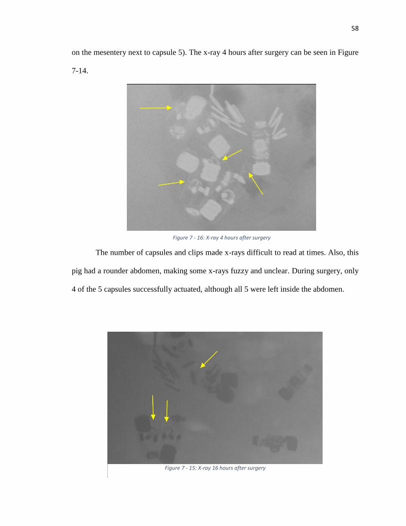
58
on the mesentery next to capsule 5). The x-ray 4 hours after surgery can be seen in Figure
7-14.
The number of capsules and clips made x-rays difficult to read at times. Also, this
pig had a rounder abdomen, making some x-rays fuzzy and unclear. During surgery, only
4 of the 5 capsules successfully actuated, although all 5 were left inside the abdomen.
Figure 7 - 16: X-ray 4 hours after surgery
Figure 7 - 15: X-ray 16 hours after surgery
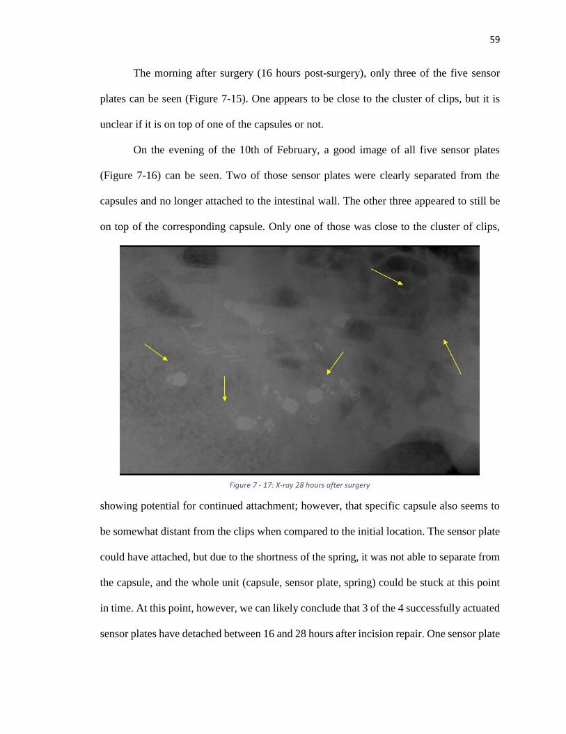
59
The morning after surgery (16 hours post-surgery), only three of the five sensor
plates can be seen (Figure 7-15). One appears to be close to the cluster of clips, but it is
unclear if it is on top of one of the capsules or not.
On the evening of the 10th of February, a good image of all five sensor plates
(Figure 7-16) can be seen. Two of those sensor plates were clearly separated from the
capsules and no longer attached to the intestinal wall. The other three appeared to still be
on top of the corresponding capsule. Only one of those was close to the cluster of clips,
showing potential for continued attachment; however, that specific capsule also seems to
be somewhat distant from the clips when compared to the initial location. The sensor plate
could have attached, but due to the shortness of the spring, it was not able to separate from
the capsule, and the whole unit (capsule, sensor plate, spring) could be stuck at this point
in time. At this point, however, we can likely conclude that 3 of the 4 successfully actuated
sensor plates have detached between 16 and 28 hours after incision repair. One sensor plate
Figure 7 - 17: X-ray 28 hours after surgery
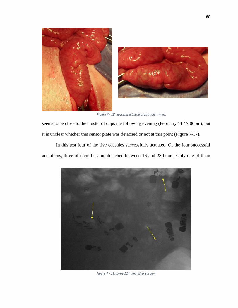
60
seems to be close to the cluster of clips the following evening (February 11th 7:00pm), but
it is unclear whether this sensor plate was detached or not at this point (Figure 7-17).
In this test four of the five capsules successfully actuated. Of the four successful
actuations, three of them became detached between 16 and 28 hours. Only one of them
Figure 7 - 19: X-ray 52 hours after surgery
Figure 7 - 18: Successful tissue aspiration in vivo.
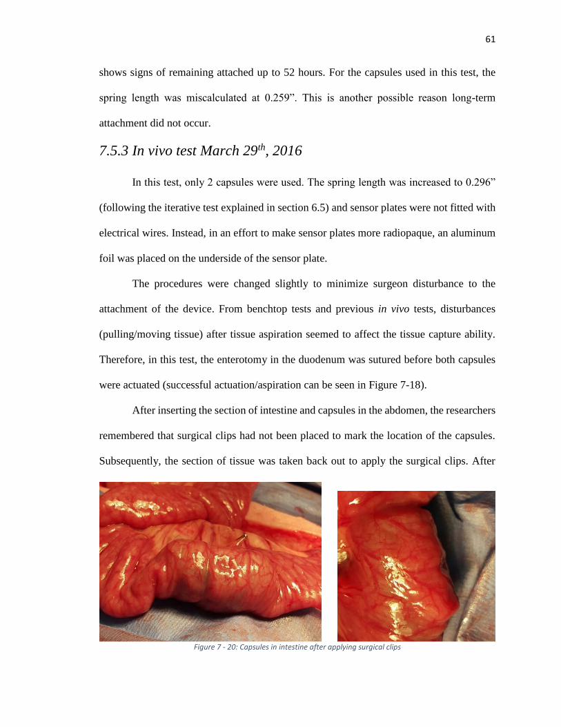
61
shows signs of remaining attached up to 52 hours. For the capsules used in this test, the
spring length was miscalculated at 0.259”. This is another possible reason long-term
attachment did not occur.
7.5.3 In vivo test March 29th, 2016
In this test, only 2 capsules were used. The spring length was increased to 0.296”
(following the iterative test explained in section 6.5) and sensor plates were not fitted with
electrical wires. Instead, in an effort to make sensor plates more radiopaque, an aluminum
foil was placed on the underside of the sensor plate.
The procedures were changed slightly to minimize surgeon disturbance to the
attachment of the device. From benchtop tests and previous in vivo tests, disturbances
(pulling/moving tissue) after tissue aspiration seemed to affect the tissue capture ability.
Therefore, in this test, the enterotomy in the duodenum was sutured before both capsules
were actuated (successful actuation/aspiration can be seen in Figure 7-18).
After inserting the section of intestine and capsules in the abdomen, the researchers
remembered that surgical clips had not been placed to mark the location of the capsules.
Subsequently, the section of tissue was taken back out to apply the surgical clips. After
Figure 7 - 20: Capsules in intestine after applying surgical clips
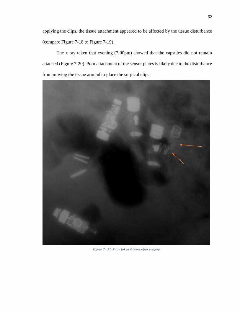
62
applying the clips, the tissue attachment appeared to be affected by the tissue disturbance
(compare Figure 7-18 to Figure 7-19).
The x-ray taken that evening (7:00pm) showed that the capsules did not remain
attached (Figure 7-20). Poor attachment of the sensor plates is likely due to the disturbance
from moving the tissue around to place the surgical clips.
Figure 7 - 21: X-ray taken 4 hours after surgery

63
7.6 Contributions
I contributed directly to all of the testing described in this chapter. The only test I
did not specifically perform myself or with a team of engineers was the seal geometry test
described in section 7.3, although I was involved in the test setup and brainstorming of the
different geometries tested.
64
Chapter 8: Discussion and Conclusion
This thesis presents the design, controls and testing of two novel devices: a
colonoscopy robot and a biosensor capsule. The goal behind each device is to provide a
less-invasive and more efficient way to obtain detailed diagnostics within the
gastrointestinal tract. From the tests described, each device shows potential for reaching
these goals. The colonoscopy robot is able to successfully obtain video while traversing 5
feet and four 90° turns. The biosensor capsule is able to aspirate and capture tissue, leaving
the sensor plate attached to the inside of the duodenum for up to 52 hours. Each device
needs improvement and further testing in order to be proven safe and efficient.
With the colonoscopy system described in this thesis, friction is believed to be
reduced, and subsequently, much of the pain and discomfort associated with traditional
colonoscopy could be mitigated although this has not been proven. Reducing this pain will
likely result in a better patient experience with colonoscopy, which then will result in more
patients submitting to routine colonoscopies and fewer mortalities due to colon cancer.
Some safety concerns have been discussed with the use of pneumatics inside the
colon. When the latex tube bursts, the rupture is rather violent; however, if water were used
in this device, the rupture would likely be much less violent. Another option to improve
safety would be to use a different material in place of the latex; a rubber material that
requires less pressure to inflate could be safer overall. Safety is extremely important, and
these theories should be explored in further development.
Another question raised in the development of the colonoscopy device is how the
device would be removed. Just as the robot tip is advanced by the inflation of the latex
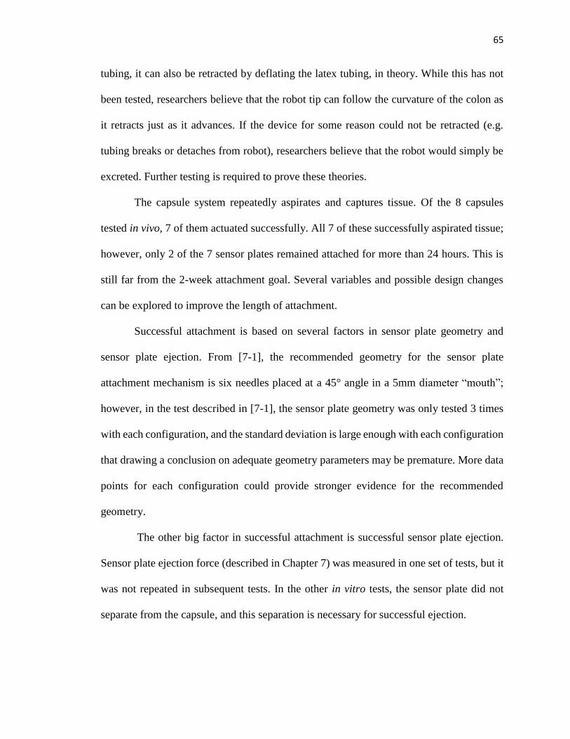
65
tubing, it can also be retracted by deflating the latex tubing, in theory. While this has not
been tested, researchers believe that the robot tip can follow the curvature of the colon as
it retracts just as it advances. If the device for some reason could not be retracted (e.g.
tubing breaks or detaches from robot), researchers believe that the robot would simply be
excreted. Further testing is required to prove these theories.
The capsule system repeatedly aspirates and captures tissue. Of the 8 capsules
tested in vivo, 7 of them actuated successfully. All 7 of these successfully aspirated tissue;
however, only 2 of the 7 sensor plates remained attached for more than 24 hours. This is
still far from the 2-week attachment goal. Several variables and possible design changes
can be explored to improve the length of attachment.
Successful attachment is based on several factors in sensor plate geometry and
sensor plate ejection. From [7-1], the recommended geometry for the sensor plate
attachment mechanism is six needles placed at a 45° angle in a 5mm diameter “mouth”;
however, in the test described in [7-1], the sensor plate geometry was only tested 3 times
with each configuration, and the standard deviation is large enough with each configuration
that drawing a conclusion on adequate geometry parameters may be premature. More data
points for each configuration could provide stronger evidence for the recommended
geometry.
The other big factor in successful attachment is successful sensor plate ejection.
Sensor plate ejection force (described in Chapter 7) was measured in one set of tests, but it
was not repeated in subsequent tests. In the other in vitro tests, the sensor plate did not
separate from the capsule, and this separation is necessary for successful ejection.
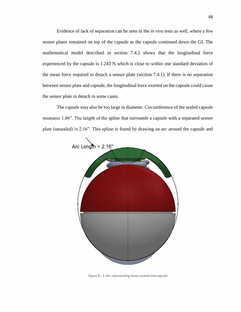
66
Evidence of lack of separation can be seen in the in vivo tests as well, where a few
sensor plates remained on top of the capsule as the capsule continued down the GI. The
mathematical model described in section 7.4.2 shows that the longitudinal force
experienced by the capsule is 1.243 N which is close to within one standard deviation of
the mean force required to detach a sensor plate (section 7.4.1). If there is no separation
between sensor plate and capsule, the longitudinal force exerted on the capsule could cause
the sensor plate to detach in some cases.
The capsule may also be too large in diameter. Circumference of the sealed capsule
measures 1.86”. The length of the spline that surrounds a capsule with a separated sensor
plate (unsealed) is 2.16”. This spline is found by drawing an arc around the capsule and
Figure 8 - 1: Arc representing tissue sucked into capsule
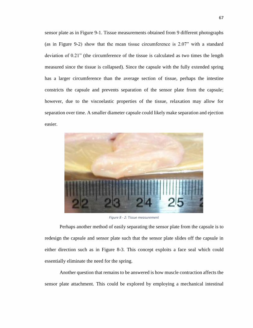
67
sensor plate as in Figure 9-1. Tissue measurements obtained from 9 different photographs
(as in Figure 9-2) show that the mean tissue circumference is 2.07” with a standard
deviation of 0.21” (the circumference of the tissue is calculated as two times the length
measured since the tissue is collapsed). Since the capsule with the fully extended spring
has a larger circumference than the average section of tissue, perhaps the intestine
constricts the capsule and prevents separation of the sensor plate from the capsule;
however, due to the viscoelastic properties of the tissue, relaxation may allow for
separation over time. A smaller diameter capsule could likely make separation and ejection
easier.
Perhaps another method of easily separating the sensor plate from the capsule is to
redesign the capsule and sensor plate such that the sensor plate slides off the capsule in
either direction such as in Figure 8-3. This concept exploits a face seal which could
essentially eliminate the need for the spring.
Another question that remains to be answered is how muscle contraction affects the
sensor plate attachment. This could be explored by employing a mechanical intestinal
Figure 8 - 2: Tissue measurement
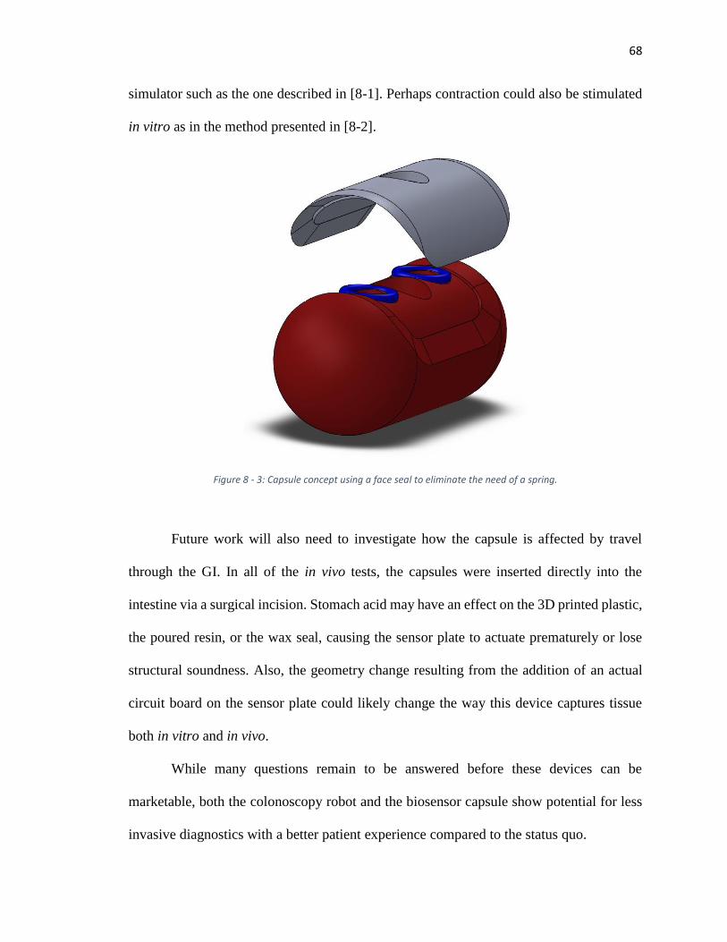
68
simulator such as the one described in [8-1]. Perhaps contraction could also be stimulated
in vitro as in the method presented in [8-2].
Future work will also need to investigate how the capsule is affected by travel
through the GI. In all of the in vivo tests, the capsules were inserted directly into the
intestine via a surgical incision. Stomach acid may have an effect on the 3D printed plastic,
the poured resin, or the wax seal, causing the sensor plate to actuate prematurely or lose
structural soundness. Also, the geometry change resulting from the addition of an actual
circuit board on the sensor plate could likely change the way this device captures tissue
both in vitro and in vivo.
While many questions remain to be answered before these devices can be
marketable, both the colonoscopy robot and the biosensor capsule show potential for less
invasive diagnostics with a better patient experience compared to the status quo.
Figure 8 - 3: Capsule concept using a face seal to eliminate the need of a spring.
69
References
[2-1] U.S. Cancer Statistics Working Group. United States Cancer Statistics: 2010 Colon
and Rectum Invasive Cancer Incidence Counts by U.S. Census Region and Division,
State and Metropolitan Area, and Race and Ethnicity, United States (Table
B.4.1MF).Available at www.cdc.gov/uscs.. Accessed May 28th, 2015.
[2-2] Joseph DA, DeGroff AS, Hayes NS, Wong FL, Plescia M. The Colorectal Cancer
Control Program: partnering to increase population level screening. Gastrointestinal
endoscopy. 2011 Mar 31;73(3):429-34.
[2-3] Klabunde CN, Lanier D, Nadel MR, McLeod C, Yuan G, Vernon SW. Colorectal
cancer screening by primary care physicians: recommendations and practices, 2006-
2007. Am J Prev Med. 2009; 37: 8-16.
[2-4] CDC. Vital Signs: Colorectal Cancer Screening Test Use--United States, 2012.
MMWR Morb Mortal Wkly Rep 2012;62:13-20.
[2-5] Chen G, Pham MT, Redarce T. Sensor-based guidance control of a continuum robot
for a semi-autonomous colonoscopy. Robotics and autonomous systems. 2009 Jun
30;57(6):712-22.
[2-6] Zuo J, Yan G, Gao Z. A micro creeping robot for colonoscopy based on the
earthworm. Journal of Medical Engineering & Technology. 2005 Jan 1;29(1):1-7.
[2-7] Long G, Fritscher-Ravens A, Mosse CA, Mills T, Swain P. The Cath-Cam: a new
concept in colonoscopy. Gastrointestinal endoscopy. 2006 Dec 31;64(6):997-1001.
[2-8] Vucelic B, Rex D, Pulanic R, Pfefer J, Hrstic I, Levin B, Halpern Z, Arber N. The
aer-o-scope: proof of concept of a pneumatic, skill-independent, self-propelling, self-
navigating colonoscope. Gastroenterology. 2006 Mar 31;130(3):672-7.
[2-9] Tumino E, Sacco R, Bertini M, Bertoni M, Parisi G, Capria A. Endotics system vs
colonoscopy for the detection of polyps. World J Gastroenterol. 2010 Nov
21;16(43):5452-6.
[2-10] Valdastri P, Simi M, Webster III RJ. Advanced technologies for gastrointestinal
endoscopy. Annual review of biomedical engineering. 2012 Aug 15;14:397-429.
[2-11] Loeve A, Breedveld P, Dankelman J. Scopes too flexible... and too stiff. IEEE pulse.
2010 Nov 1;1(3):26-41.
[2-12] Welch, C.R., Reid, J.D. Looping Formation During Colonoscopy – a Simulation.
14th International LS-Dyna Users Conference. June 2016.
70
[2-13] Hefny AF, C.P., Abu-Zidan FM, The role of ultrasound in the management of
intestinal obstruction. Journal of Emergencies Trauma and Shock, 2012. 5(1): p. 84-
6.
[2-14] Hu H, Wang P, Zhao B, Li M, Sun L. Design of a novel snake-like robotic
colonoscope. InRobotics and Biomimetics (ROBIO), 2009 IEEE International
Conference on 2009 Dec 19 (pp. 1957-1961). IEEE.
[2-15] Hu H, Weida L, Juan L, Mantian L, Lining S. Two-dimension guidance control and
simulation of a colonoscopic robot. InStrategic Technology (IFOST), 2011 6th
International Forum on 2011 Aug 22 (Vol. 1, pp. 323-327). IEEE.
[2-16] Fisher DA, Maple JT, Ben-Menachem T, Cash BD, Decker GA, Early DS, Evans
JA, Fanelli RD, Fukami N, Hwang JH, Jain R. Complications of colonoscopy.
Gastrointestinal endoscopy. 2011 Jan 10;74(4):745-52.
[2-17] Zubarik R, Fleischer DE, Mastropietro C, Lopez J, Carroll J, Benjamin S, Eisen G.
Prospective analysis of complications 30 days after outpatient colonoscopy.
Gastrointestinal endoscopy. 1999 Sep 30;50(3):322-8.
[2-18] Ko CW, Riffle S, Shapiro JA, Saunders MD, Lee SD, Tung BY, Kuver R, Larson
AM, Kowdley KV, Kimmey MB. Incidence of minor complications and time lost
from normal activities after screening or surveillance colonoscopy. Gastrointestinal
endoscopy. 2007 Apr 30;65(4):648-56.
[3-1] Pourghodrat, Abolfazl, Fluid powered miniature in-vivo robots for minimally
invasive surgery (MIS) (2014). Mechanical (and Materials) Engineering --
Dissertations, Theses, and Student Research. Paper 74.
http://digitalcommons.unl.edu/mechengdiss/74
[3-2] Weissten, Eric W. “Archmedes’ Spiral.” From MathWorld—A Wolfram Web
Resource. http://mathworld.wolfram.com/ArchimedesSpiral.html
[5-1] Cohen SA, Ephrath H, Lewis JD, Klevens A, Bergwerk A, Liu S, Patel D, Reed-
Knight B, Stallworth A, Wakhisi T, Gold BD. Pediatric capsule endoscopy: review
of the small bowel and patency capsules. Journal of pediatric gastroenterology and
nutrition. 2012 Mar 1;54(3):409-13.
[5-2] Leighton JA, Gralnek IM, Cohen SA, Toth E, Cave DR, Wolf DC, Mullin GE,
Ketover SR, Legnani PE, Seidman EG, Crowell MD. Capsule endoscopy is superior
to small-bowel follow-through and equivalent to ileocolonoscopy in suspected
Crohn's disease. Clinical Gastroenterology and Hepatology. 2014 Apr 30;12(4):609-
15.
71
[5-3] Liao Z, Gao R, Xu C, Li ZS. Indications and detection, completion, and retention
rates of small-bowel capsule endoscopy: a systematic review. Gastrointestinal
endoscopy. 2010 Feb 28;71(2):280-6.
[5-4] Neumann H, Fry LC, Neurath MF. Review article on current applications and future
concepts of capsule endoscopy. Digestion. 2013 Jan 10;87(2):91-9.
[5-5] Kim B, Park S, Jee CY, Yoon SJ. An earthworm-like locomotive mechanism for
capsule endoscopes. InIntelligent Robots and Systems, 2005.(IROS 2005). 2005
IEEE/RSJ International Conference on 2005 Aug 2 (pp. 2997-3002). IEEE.
[5-6] Tognarelli S, Quaglia C, Valdastri P, Susilo E, Menciassi A, Dario P. Innovative
stopping mechanism for esophageal wireless capsular endoscopy. Procedia
Chemistry. 2009 Sep 30;1(1):485-8.
[5-7] Salerno M, Mazzocchi T, Ranzani T, Mulana F, Dario P, Menciassi A. Safety systems
in magnetically driven wireless capsule endoscopy. InIntelligent Robots and Systems
(IROS), 2013 IEEE/RSJ International Conference on 2013 Nov 3 (pp. 3090-3095).
IEEE.
[5-8] Charbel A, Julien M, Gerard S, Fabien K, Yan HC, Georges A, Alain L. Wireless
communicating implant for record of vital diagnosis parameters. InMicroelectronics
Packaging Conference (EMPC), 2013 European 2013 Sep 9 (pp. 1-6). IEEE.
[5-9] Fu X, Chen W, Ye S, Tu Y, Tang Y, Li D, Chen H, Jiang K. A wireless implantable
sensor network system for in vivo monitoring of physiological signals. Information
Technology in Biomedicine, IEEE Transactions on. 2011 Jul;15(4):577-84.
[5-10] Xie W, Terry BS. Biomimetic Attachment to the Gastrointestinal Tract. Journal of
Medical Devices. 2014 Sep 1;8(3):030909.
[5-11] Iddan G, Meron G, Glukhovsky A, Swain P. Wireless capsule endoscopy. Nature.
2000 May;405:417.
[5-12] Karargyris A, Koulaouzidis A. OdoCapsule: next-generation wireless capsule
endoscopy with accurate lesion localization and video stabilization capabilities.
Biomedical Engineering, IEEE Transactions on. 2015 Jan;62(1):352-60.
[5-13] Son D, Lee J, Qiao S, Ghaffari R, Kim J, Lee JE, Song C, Kim SJ, Lee DJ, Jun SW,
Yang S. Multifunctional wearable devices for diagnosis and therapy of movement
disorders. Nature Nanotechnology. 2014 May 1;9(5):397-404.
[5-14] Hung K, Zhang YT, Tai B. Wearable medical devices for tele-home healthcare.
InEngineering in Medicine and Biology Society, 2004. IEMBS'04. 26th Annual
International Conference of the IEEE 2004 Sep 1 (Vol. 2, pp. 5384-5387). IEEE.
72
[5-15] Medtronic. CareLink system. [Online]. Available: http://www.medtronic.com/
physician/carelink/index.html. Accessed April. 20, 2016.
[5-16] Medtronic. What is Personal CGM? [Online]. Available: http://www.professional.
medtronicdiabetes.com/personal-cgm. Accessed April 20, 2016
[5-17] Loizou PC. Mimicking the human ear. Signal Processing Magazine, IEEE. 1998
Sep;15(5):101-30.
[5-18] Shantz JA, Veillette CJ. The application of wearable technology in surgery: ensuring
the positive impact of the wearable revolution on surgical patients. Frontiers in
surgery. 2014;1.
[5-19] Appelboom G, Yang AH, Christophe BR, Bruce EM, Slomian J, Bruyère O, Bruce
SS, Zacharia BE, Reginster JY, Connolly ES. The promise of wearable activity
sensors to define patient recovery. Journal of Clinical Neuroscience. 2014 Jul
31;21(7):1089-93.
[5-20] Fitbit. Fitbit Charge HR™. [Online]. Available: https://www.fitbit.com/chargehr?
gclid=Cj0KEQjw0dy4BRCuuL_e5MeqmNABEiQAq8iNI2cYl5gXucddXb1N7726
KEEJzX6QyvR5X6LRPQtPDT0aAib08P8HAQ. Accessed April 20, 2016.
[6-1] Xie W, Kothari V, Terry BS. A bio-inspired attachment mechanism for long-term
adhesion to the small intestine. Biomedical microdevices. 2015 Aug 1;17(4):1-9.
[6-2] Oberg, E., Jones, F.D., Holbrook, H.L., Ryffel, H.H.. Machinery’s Handbook. 26th
Edition. New York 2000. Pp. 2482-2487
[7-1] Miftahof RN. The wave phenomena in smooth muscle syncytia. In silico biology.
2005 Jan 1;5(5, 6):479-98.
[8-1] Slawinski PR, Oleynikov D, Terry BS. Intestinal biomechanics simulator for robotic
capsule endoscope validation. Journal of medical engineering & technology. 2015
Jan 2;39(1):54-9.
[8-2] Costall B, Naylor RJ, Tuladhar BR. 5‐HT4 receptor mediated facilitation of the
emptying phase of the peristaltic reflex in the guinea‐pig isolated ileum. British
journal of pharmacology. 1993 Dec 1;110(4):1572-8.
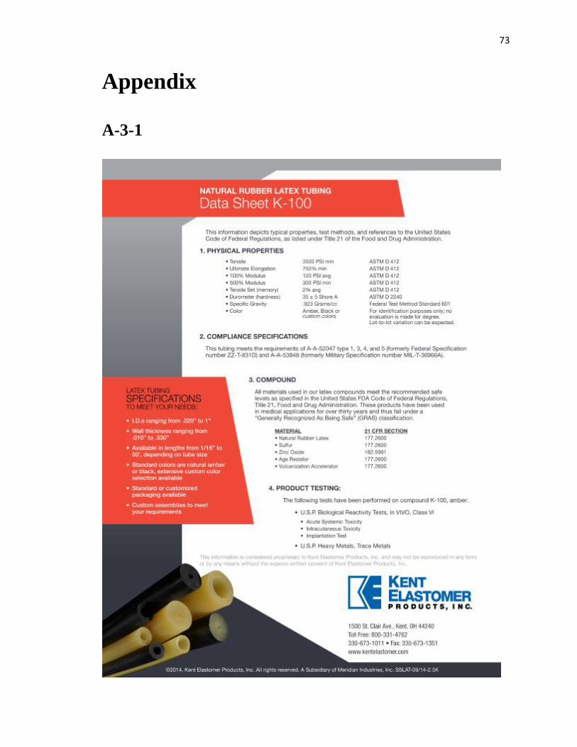
73
Appendix
A-3-1
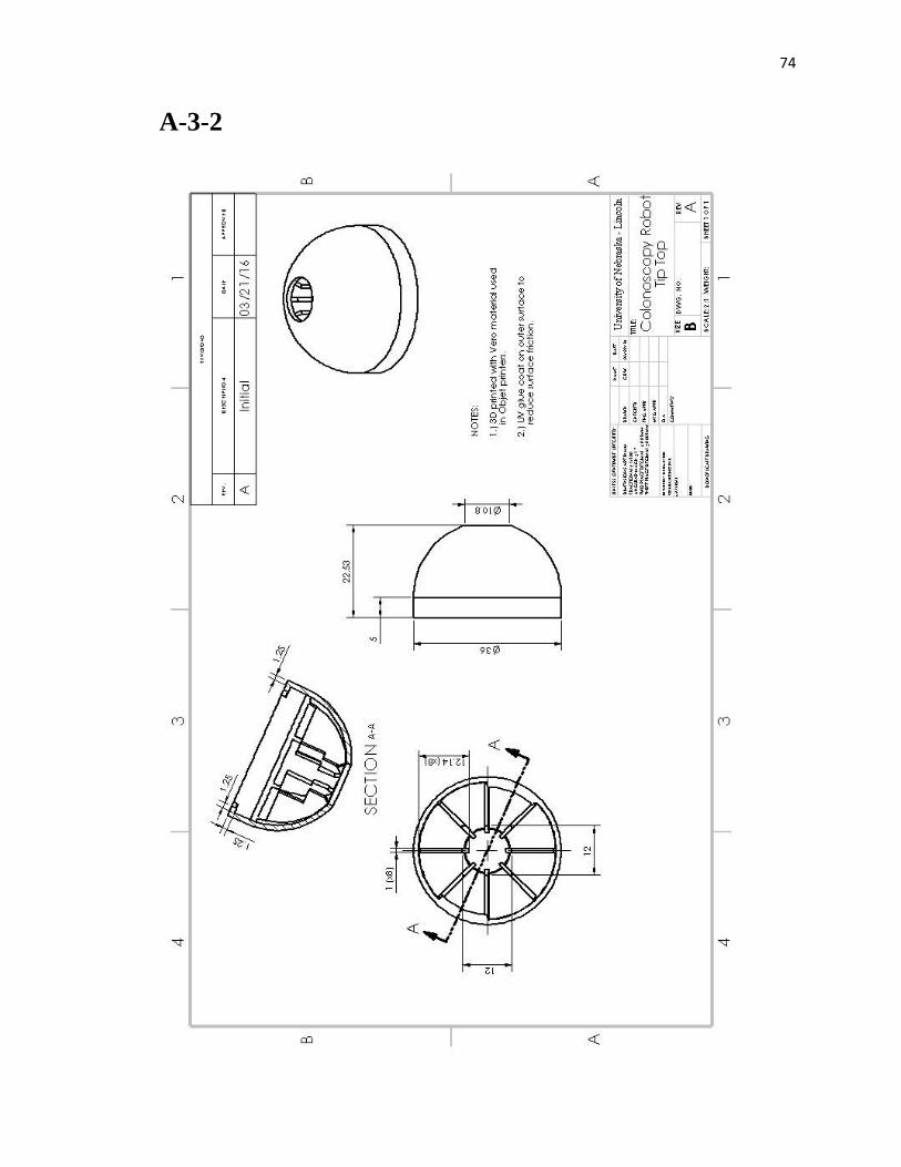
74
A-3-2
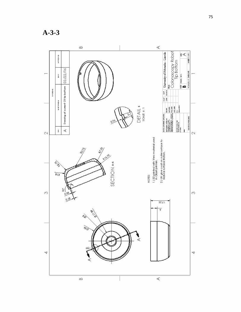
75
A-3-3
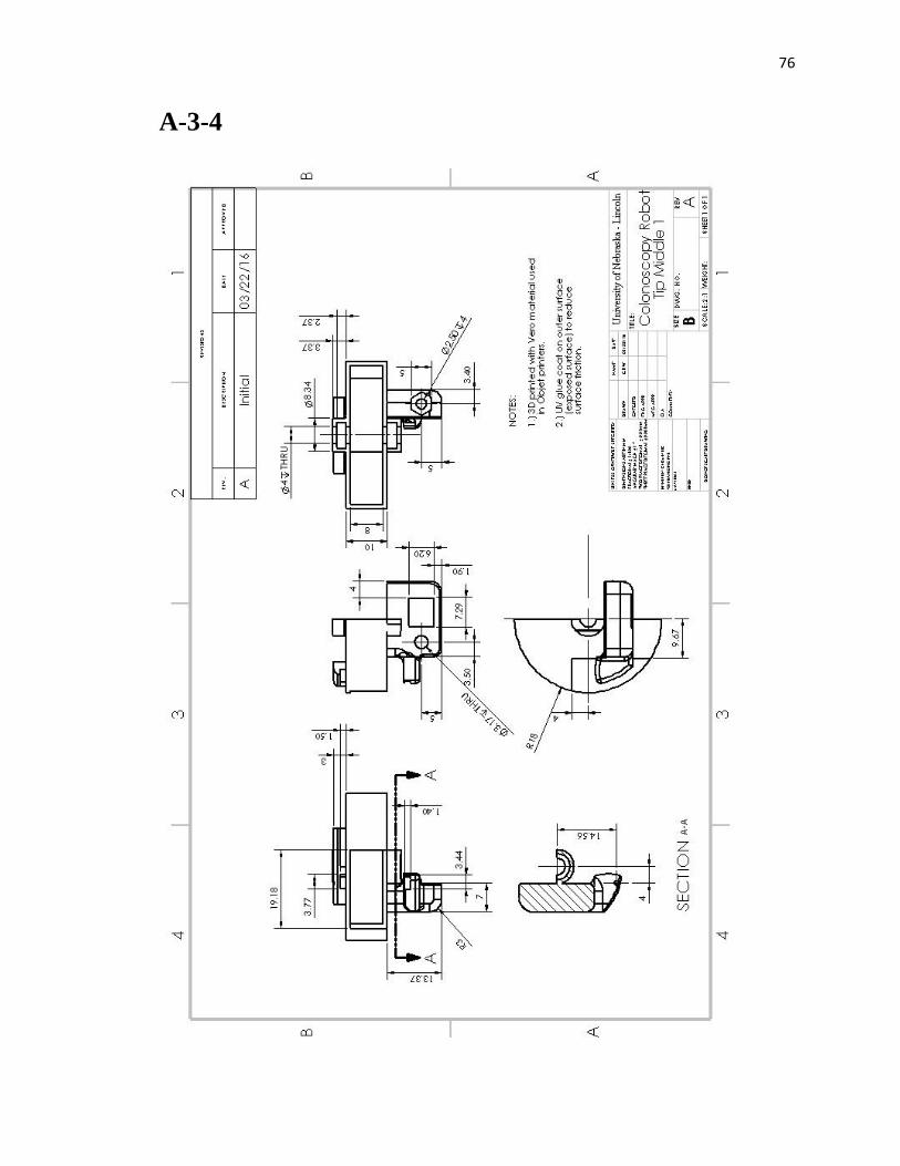
76
A-3-4
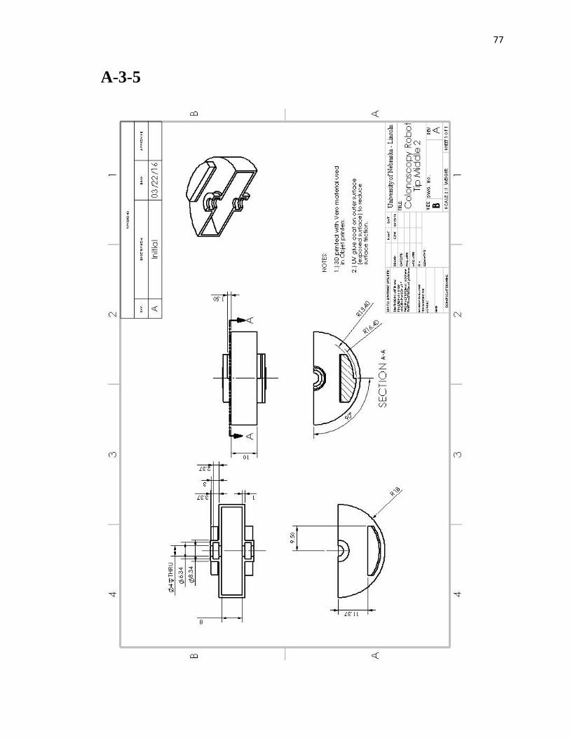
77
A-3-5
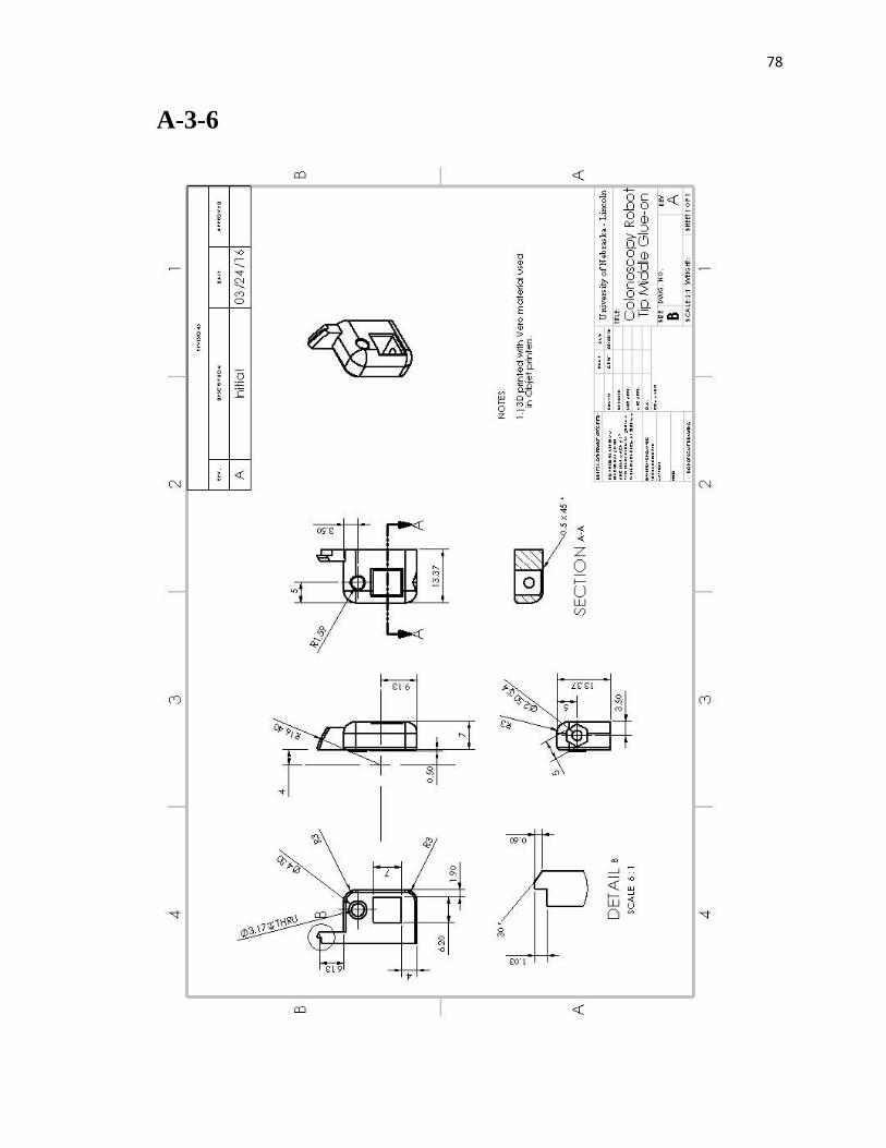
78
A-3-6

79
A-3-6
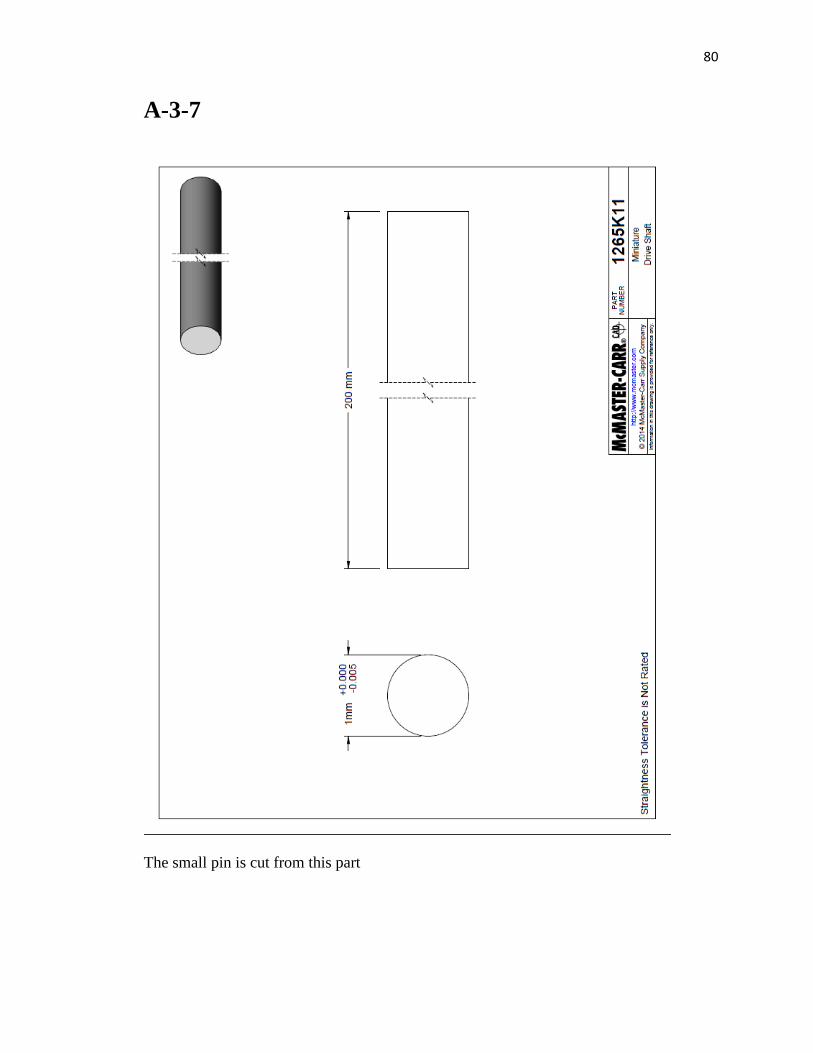
80
A-3-7
The small pin is cut from this part
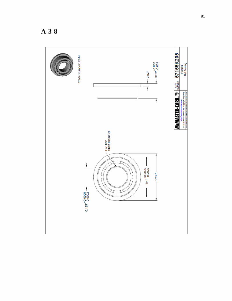
81
A-3-8
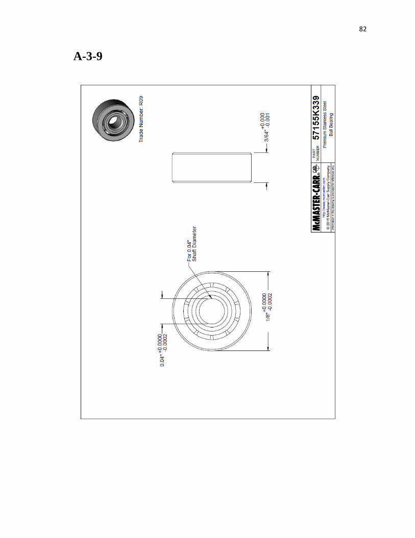
82
A-3-9
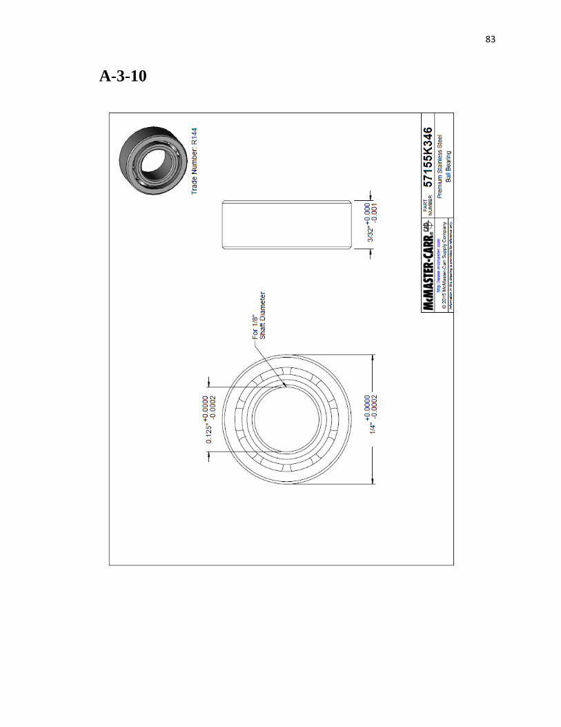
83
A-3-10
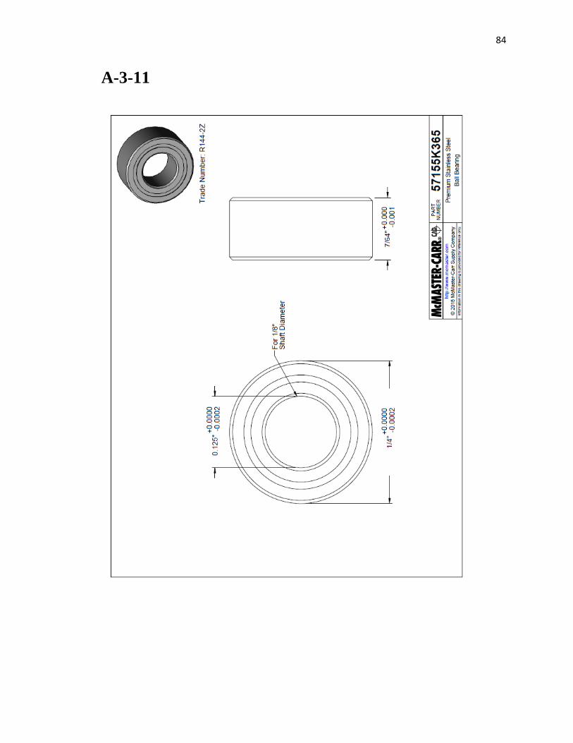
84
A-3-11
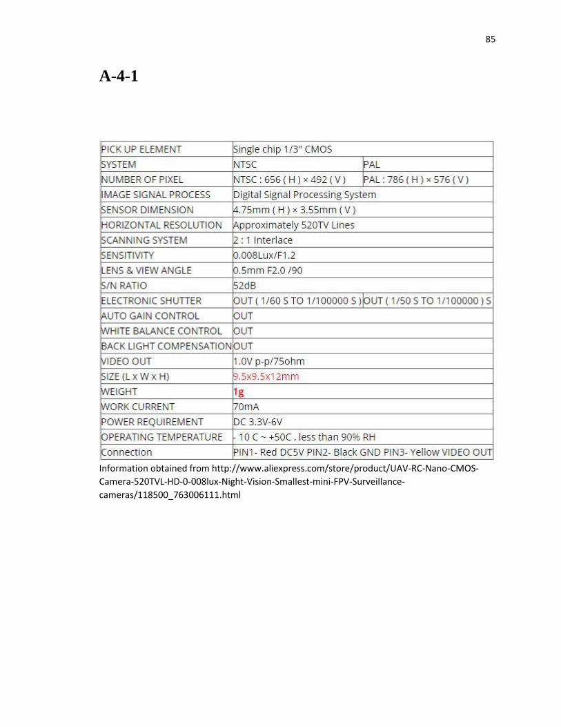
85
A-4-1
Information obtained from http://www.aliexpress.com/store/product/UAV-RC-Nano-CMOS-
Camera-520TVL-HD-0-008lux-Night-Vision-Smallest-mini-FPV-Surveillance-
cameras/118500_763006111.html
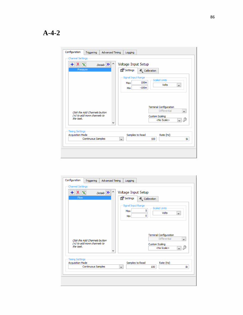
86
A-4-2
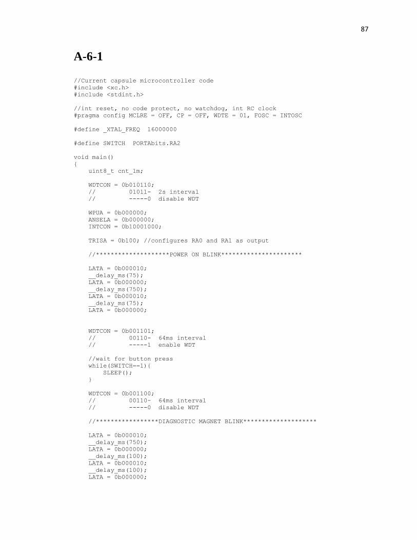
87
A-6-1
//Current capsule microcontroller code
#include <xc.h>
#include <stdint.h>
//int reset, no code protect, no watchdog, int RC clock
#pragma config MCLRE = OFF, CP = OFF, WDTE = 01, FOSC = INTOSC
#define _XTAL_FREQ 16000000
#define SWITCH PORTAbits.RA2
void main()
{
uint8_t cnt_1m;
WDTCON = 0b010110;
// 01011- 2s interval
// -----0 disable WDT
WPUA = 0b000000;
ANSELA = 0b000000;
INTCON = 0b10001000;
TRISA = 0b100; //configures RA0 and RA1 as output
//********************POWER ON BLINK**********************
LATA = 0b000010;
__delay_ms(75);
LATA = 0b000000;
__delay_ms(750);
LATA = 0b000010;
__delay_ms(75);
LATA = 0b000000;
WDTCON = 0b001101;
// 00110- 64ms interval
// -----1 enable WDT
//wait for button press
while(SWITCH==1){
SLEEP();
}
WDTCON = 0b001100;
// 00110- 64ms interval
// -----0 disable WDT
//*****************DIAGNOSTIC MAGNET BLINK********************
LATA = 0b000010;
__delay_ms(750);
LATA = 0b000000;
__delay_ms(100);
LATA = 0b000010;
__delay_ms(100);
LATA = 0b000000;
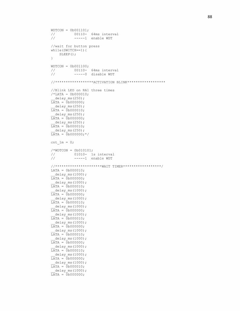
88
WDTCON = 0b001101;
// 00110- 64ms interval
// -----1 enable WDT
//wait for button press
while(SWITCH==1){
SLEEP();
}
WDTCON = 0b001100;
// 00110- 64ms interval
// -----0 disable WDT
//******************ACTIVATION BLINK******************
//Blink LED on RA1 three times
/*LATA = 0b000010;
__delay_ms(250);
LATA = 0b000000;
__delay_ms(250);
LATA = 0b000010;
__delay_ms(250);
LATA = 0b000000;
__delay_ms(250);
LATA = 0b000010;
__delay_ms(250);
LATA = 0b000000;*/
cnt_1m = 0;
/*WDTCON = 0b010101;
// 01010- 1s interval
// -----1 enable WDT
//**********************WAIT TIMER******************/
LATA = 0b000010;
__delay_ms(1000);
LATA = 0b000000;
__delay_ms(1000);
LATA = 0b000010;
__delay_ms(1000);
LATA = 0b000000;
__delay_ms(1000);
LATA = 0b000010;
__delay_ms(1000);
LATA = 0b000000;
__delay_ms(1000);
LATA = 0b000010;
__delay_ms(1000);
LATA = 0b000000;
__delay_ms(1000);
LATA = 0b000010;
__delay_ms(1000);
LATA = 0b000000;
__delay_ms(1000);
LATA = 0b000010;
__delay_ms(1000);
LATA = 0b000000;
__delay_ms(1000);
LATA = 0b000010;
__delay_ms(1000);
LATA = 0b000000;
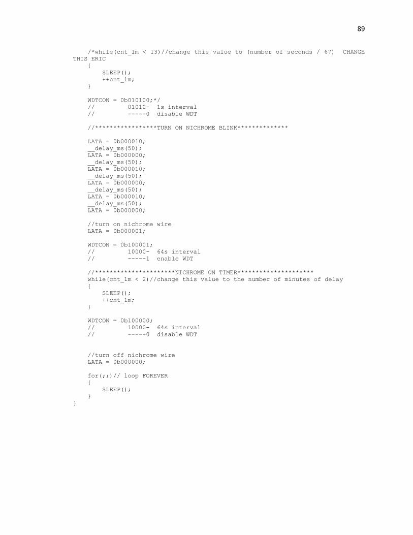
89
/*while(cnt_1m < 13)//change this value to (number of seconds / 67) CHANGE
THIS ERIC
{
SLEEP();
++cnt_1m;
}
WDTCON = 0b010100;*/
// 01010- 1s interval
// -----0 disable WDT
//*****************TURN ON NICHROME BLINK**************
LATA = 0b000010;
__delay_ms(50);
LATA = 0b000000;
__delay_ms(50);
LATA = 0b000010;
__delay_ms(50);
LATA = 0b000000;
__delay_ms(50);
LATA = 0b000010;
__delay_ms(50);
LATA = 0b000000;
//turn on nichrome wire
LATA = 0b000001;
WDTCON = 0b100001;
// 10000- 64s interval
// -----1 enable WDT
//**********************NICHROME ON TIMER*********************
while(cnt_1m < 2)//change this value to the number of minutes of delay
{
SLEEP();
++cnt_1m;
}
WDTCON = 0b100000;
// 10000- 64s interval
// -----0 disable WDT
//turn off nichrome wire
LATA = 0b000000;
for(;;)// loop FOREVER
{
SLEEP();
}
}
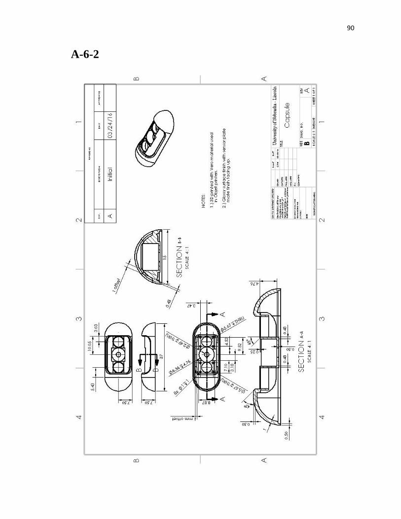
90
A-6-2
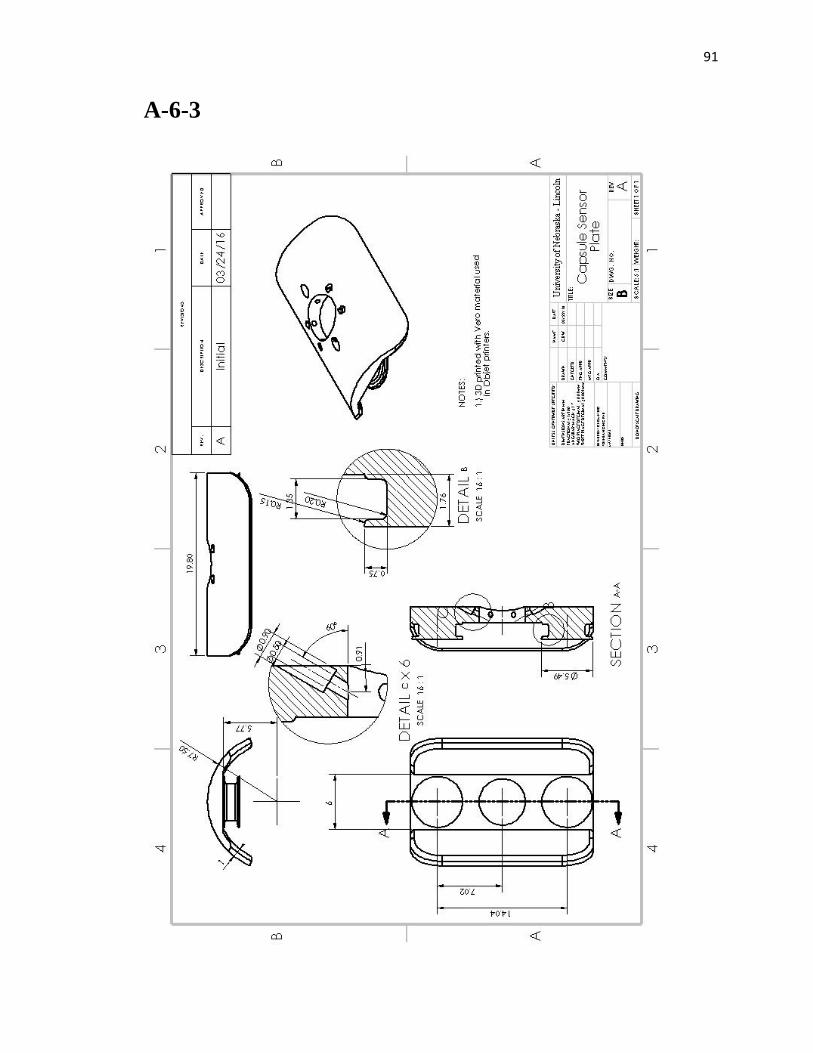
91
A-6-3
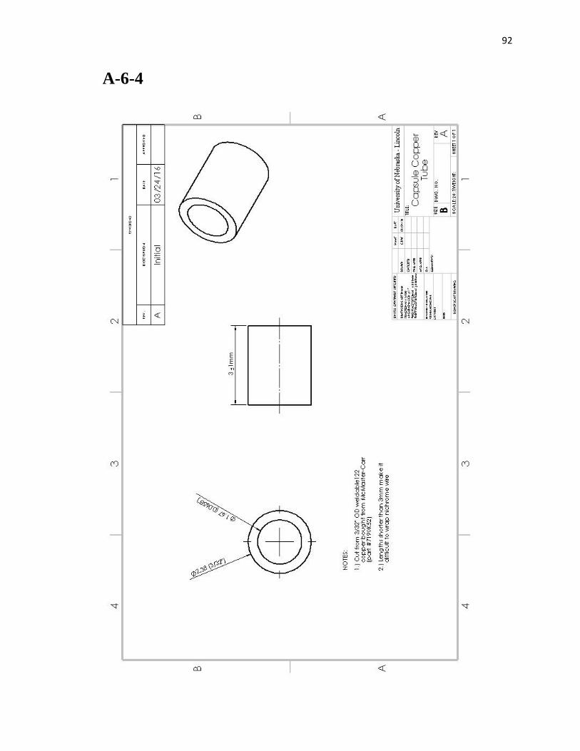
92
A-6-4
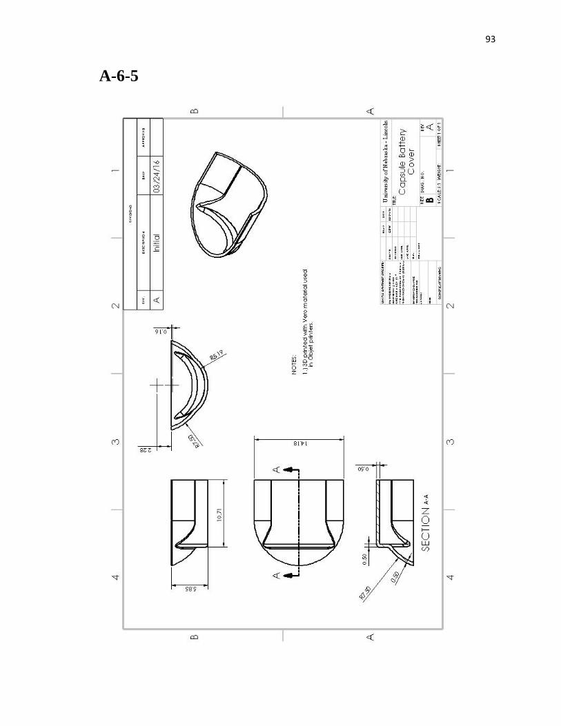
93
A-6-5
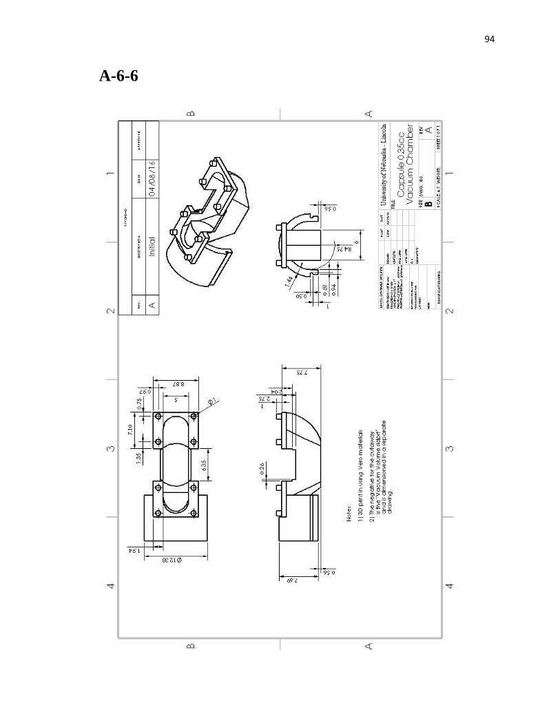
94
A-6-6
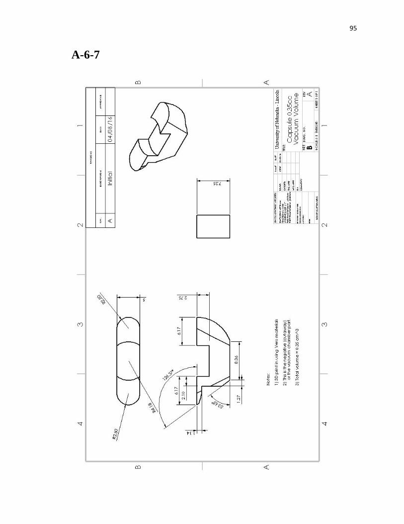
95
A-6-7
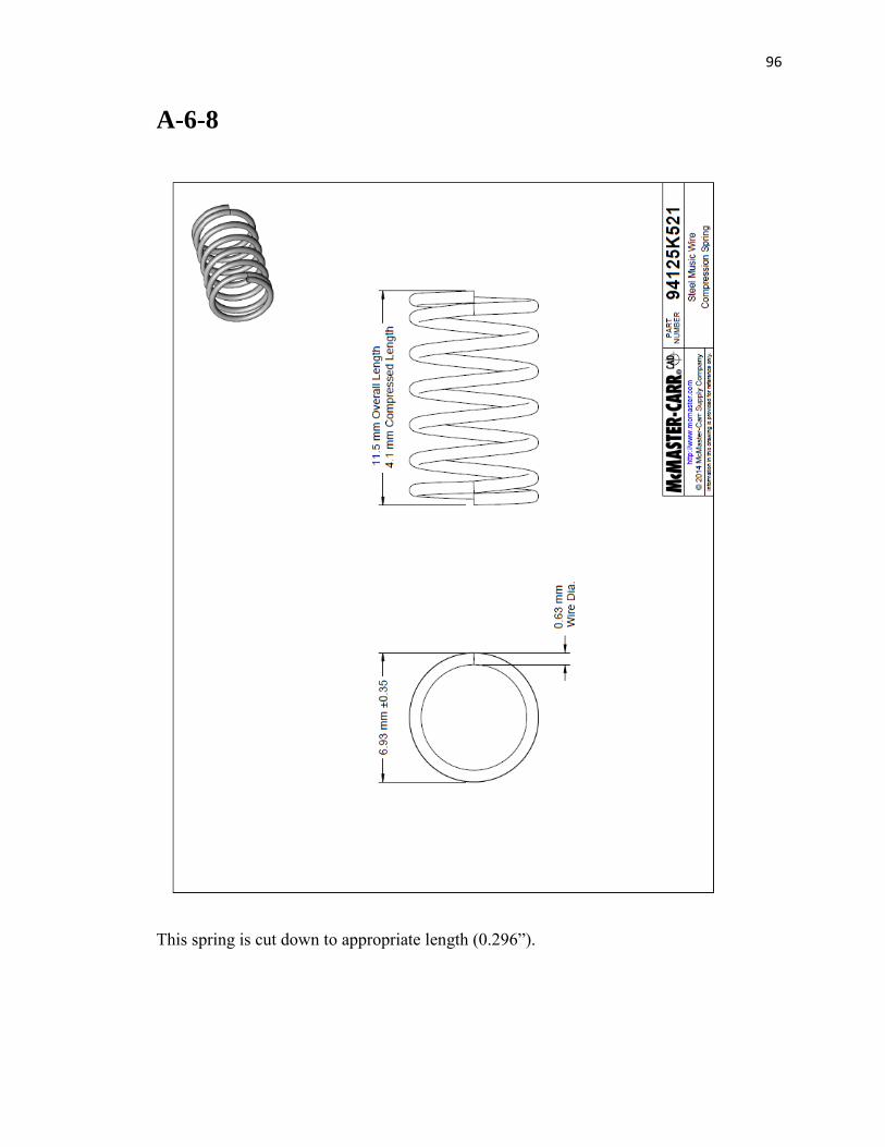
96
A-6-8
This spring is cut down to appropriate length (0.296”).
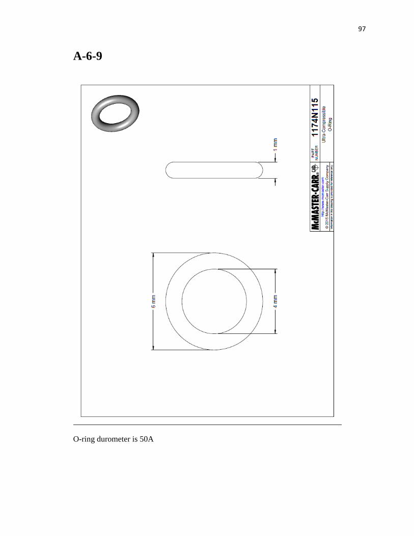
97
A-6-9
O-ring durometer is 50A
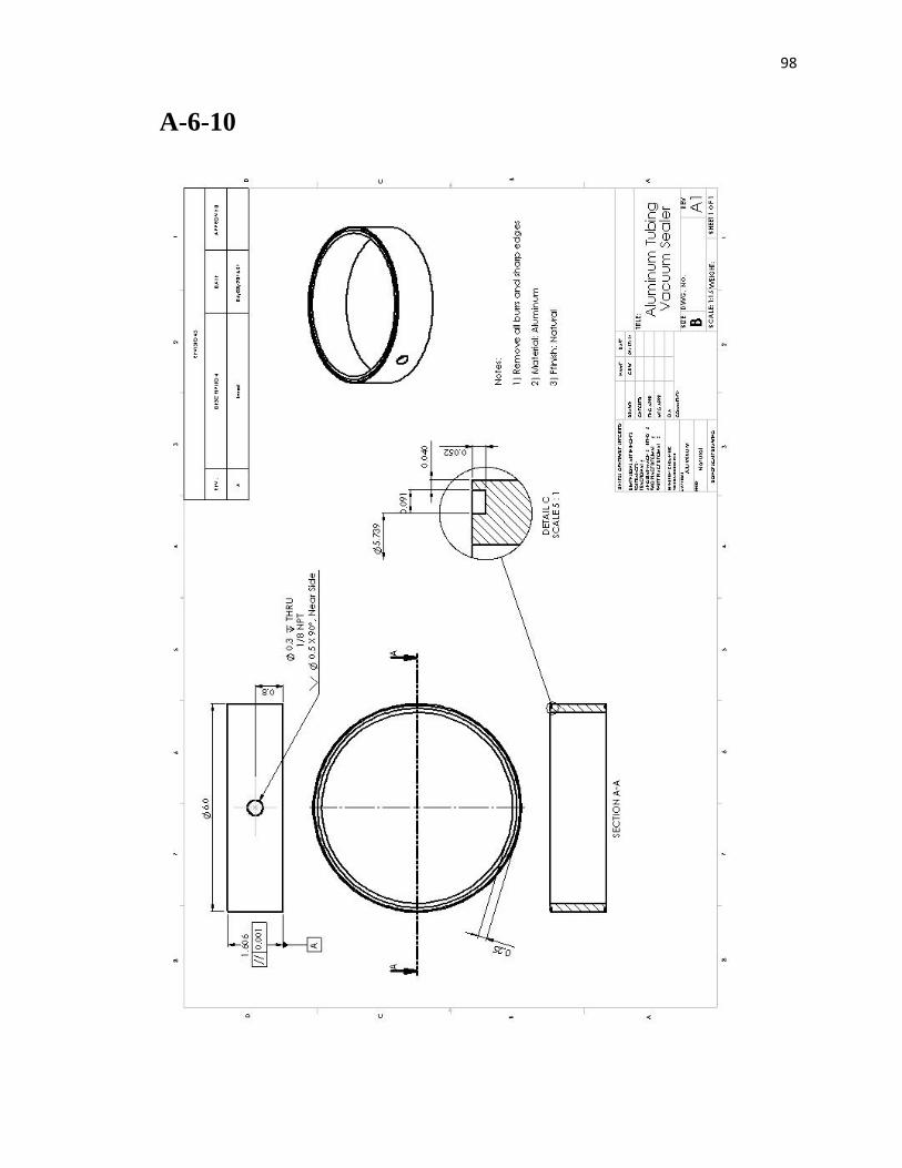
98
A-6-10
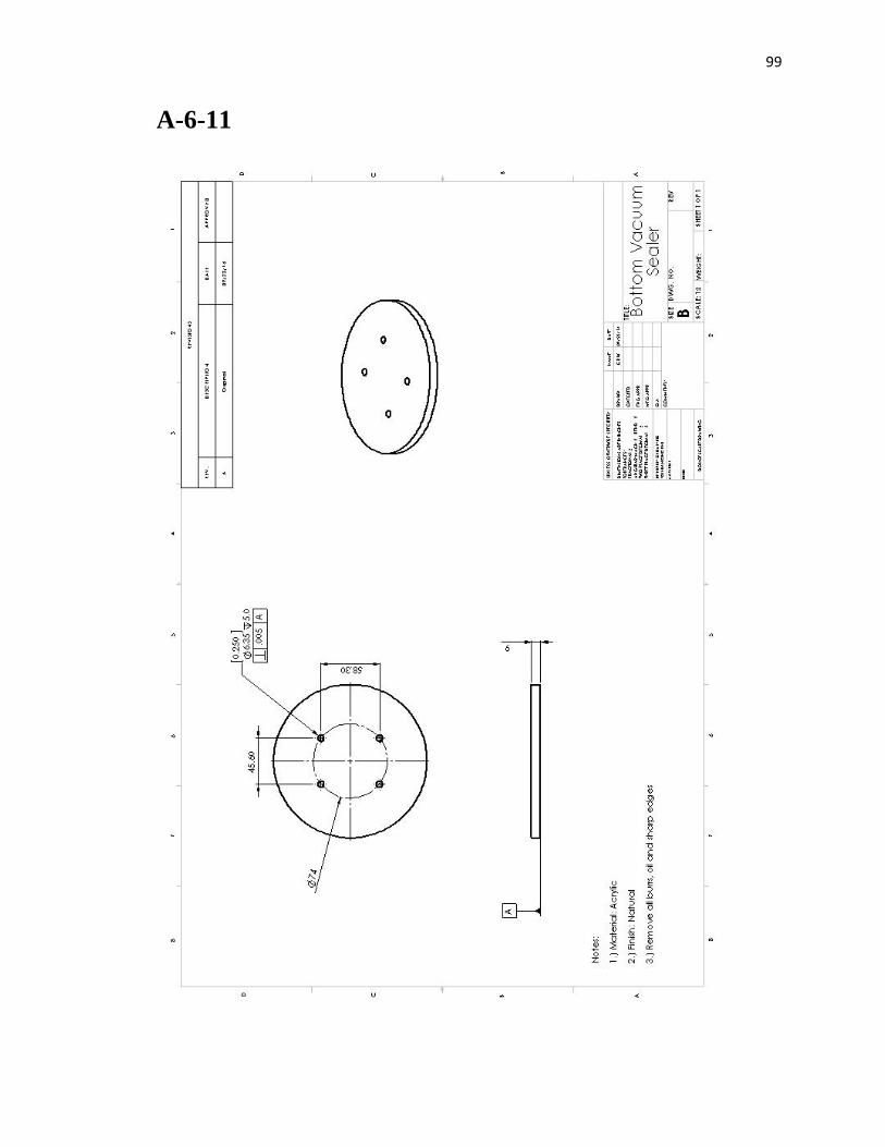
99
A-6-11
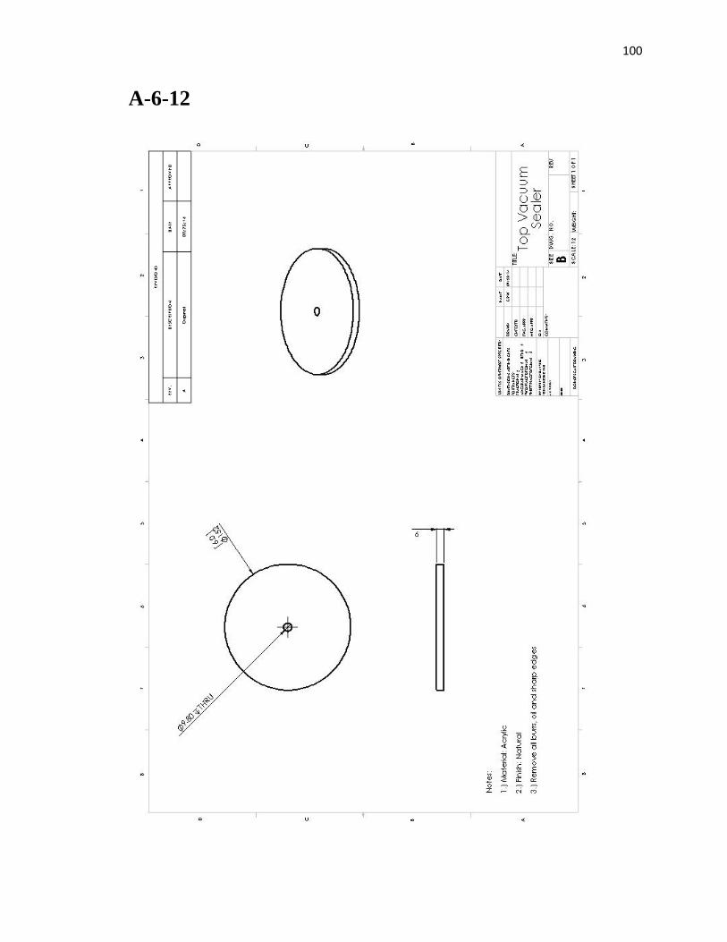
100
A-6-12

101
A-7-1
Common Capsule Issues
Issue Resolution/Cause
Capsule blinks seven times slowly followed by
two quick blinks
This is how the capsule is supposed to
funcion. After the two quick blinks,
the wax seal should heat up quickly
(10 degrees in 2 or 3 seconds,
roughly). The capsule loads most of
the voltage (should jump to 3 volts)
into the nichrome wire for 2 minutes
and then resets.
Capsule blinks seven times slowly and then seems
to reset (initial blink pattern)
There is likely a short in the reed
switch soldering pads on the circuit
board
Capsule blinks seven times slowly followed by
two quick blinks, but the wax seal does not change
in temperature or changes very slowly.
The transistor may be faulty
(overheated perhaps with soldering) or
it may not be soldered correctly. The
nichrome wire may have broken. If the
nichrome wire broke, there will no
longer be a resistance reading across it.
If solders look good and resistance
reading is good, replace transistor (or
possibly the microcontroller).
Capsule blinks seven times slowly followed by
two quick blinks but seems to reset prematurely
(<120 seconds).
Low batteries. The capsule always
functions best with new batteries.
Capsule does not blink at all
Poor battery connection, poor
soldering, or unprogrammed
microcontroller can all be likely causes
for this. Check solders, or possibly
replace microcontroller.
102
Sensor plate does not seal when vacuum pressure
clearly goes above 28 inches Hg.
Several likely scenarios: leak in the
capsule, wax does not completely seal
copper tube, spring is too long, or
sensor plate o-ring locations are
chipped. A leak can be found using the
blow test. The spring should be 0.259"
or less. Sensor plate o-ring locations
can be visually inspected.
Capsule appears to have a poor connection. This is
likely the case as it blinks when touched or when
vacuum sealed.
Poor battery connection. Readjust
battery connection leads to make better
contact with batteries.
Leak in the capsule
Two common areas for leaks are in the
battery compartment area and at the
copper tube location. A drop of cured
UV glue can go over the copper tube;
this can be easily removed with
tweezers. A finger full of vacuum
grease in the battery compartment can
plug up small holes there.