Design & Developed of a Based Home esign & Developed of a ...
63
Design & Dev Based Home Ea Department of E Dr Dept. of E veloped of a Microcont e Appliance Control Sy Using Wi-Fi Developed by: Md. Inzamul Islam ID: 2011-1-55-040 S. M. Ariful Haider ID: 2011-2-55-021 ast West University Electronics & Communication Engineerin Project Supervisor: r. Md. Habibur Rahman Professor Electrical and Electronics Engineering University Of Dhaka 1 troller ystem ng
-
Upload
khangminh22 -
Category
Documents
-
view
1 -
download
0
Transcript of Design & Developed of a Based Home esign & Developed of a ...

Design & Developed of aBased Home
East West UniversityDepartment of Electronics & Communication
Dr. Md. Habibur Rahman
Dept. of Electrical and Electronics Engineering
Design & Developed of a Microcontroller Based Home Appliance Control System
Using Wi-Fi
Developed by:
Md. Inzamul Islam ID: 2011-1-55-040
S. M. Ariful Haider ID: 2011-2-55-021
East West University
Department of Electronics & Communication Engineering
Project Supervisor: Dr. Md. Habibur Rahman
Professor Dept. of Electrical and Electronics Engineering
University Of Dhaka
1
Microcontroller Appliance Control System
Engineering

2 DECLARATION
We hereby declare that we carried out the work reported in this project in the Department of Electronics and Communication Engineering, East West University, under the supervision of Dr. Md. Habibur Rahman. We solemnly declare that to the best of our knowledge, no part of this report has been submitted elsewhere for award of a degree. All sources of knowledge used have been duly acknowledged. Signature:
........................................................................
S.M. Ariful Haider ID : 2011-2-55-021
.........................................................................
Md. Inzamul Islam ID : 2011-1-55-040
------------------------------------- Supervisor
Dr. Md. Habibur Rahman Professor, Dept. of Electrical and
Electronics Engineering University Of Dhaka

3 APPROVAL
This is to certify that the Project titled as “Design and Developing of a Microcontroller Based Home Appliance Control System Using Wi-Fi” submitted to the respected members of the Board of Examiners of the Faculty of Engineering for partial fulfillment of the requirements for the degree of Bachelor of Science in Electronics & Telecommunications Engineering by the following students and has been accepted as satisfactory.
------------------------------------------------------ Dr. Md. Habibur Rahman
Professor, Electrical and Electronics Engineering
University of Dhaka
--------------------------------------------------- Dr. Gurudas Mandal
Chairperson & Associate Professor, Dept. of Electronics and Communication
Engineering East West University
Submitted By: Md. Inzamul Islam ID : 2011-1-55-040
S.M. Ariful Haider ID : 2011-2-55-021

4 ACKNOWLEDGEMENTS
Many people deserve our thanks for their help in completing this project. We would like to thank our department for giving us this chance to do this project. We want to express our thanks and deep appreciation to our advisor Dr. Md. Habibur Rahman as he has exhausted all his knowledge and time by following up our daily progress and encouraging advices and even by sharing on the troubles. We would like to extend our thanks to the laboratory staff of ECE Dept. for their fast response and cooperation with us to get some materials we need for our case. We have special acknowledgment for our group members for their understanding each other and hard working from the beginning up to the end. Finally, we would like to thank our family and all persons who were involved with this project for their valuable help and professionalism during this project.
5 ABSTRACT
In modern days, we must use various high-tech electronic devices and equipments to get our jobs done and make the life easier. The purpose of this project is to design a control system that is able to control a system device remotely from distant places and monitoring conditions of the system web page on the Arduino and advances step by step from there. This project shows how to set up an Arduino with Ethernet shield as a web server. The web servers in this project are used to serve up web pages that can be accessed from a web browser and allows our hardware to be controlled from web browser. Starting from basic, our example for this project is simple. We want to access our device by switching ON-OFF LED and monitor analog input data acquisition from web server, which are computer or mobile phone and Arduino connected to the same network. Also we can control ( ON/OFF ) every electronic and electrical load (operated by 220V ) of our home like lights, fans, AC, refrigerators, TVs using relays with this system. The system has been designed and implemented practically. It is found that the system works perfectly.
6 TABLE OF CONTENTS
Short Contents Page TITLE PAGE 01 DECLARATION 02 APPROVAL 03 ACKNOWLEDGEMENT 04 ABSTRACT 05 TABLE OF CONTENTS 06 LIST OF FIGURE 09 CHAPTER 1. INTRODUCTION 10 1.1 Physical Computing 10 1.2 The Internet of Things 10 1.3 Energy 10 1.4 Electrical Energy 11 1.5 Purpose of this Project 11 1.6 Outline of the report 11 2. AN OVERVIEW OF MICROCONTROLLERS 12 2.1 Introduction 12 2.2 Microcontroller 12 2.3 Advantages of Microcontroller 12 2.4 Arduino-UNO 13 2.5 Figure of Arduino-UNO 13 2.6 History of Arduino-UNO 14 2.7 Development 14 2.8 Evaluation 15 3. THEORY BEHIND THE PROJECT 16 3.1 Introduction 3.2 Architecture of Arduino-UNO 16 3.2.1 Power 17 3.2.2 Memory 17 3.2.3 Input and Output 18 3.2.4 Power LED Indicator 18 3.2.5 Reset Button19 3.2.6 TX RX LEDs 19 3.2.7 Main IC 19 3.2.8 Voltage Regulator 19

7 3.2.9 Technical specs 20 3.2.9 Schematic Diagram 20 3.3 Getting started with Arduino Software 21 3.3.1 The Integrated Development Environment (IDE) 21 3.3.2 IDE Parts 21 3.4 Arduino Ethernet Shield 22 3.4.1 Architecture of Arduino Ethernet Shield 23 3.4.2 Description 24 3.4.3 Connecting the Shield 25 3.4.4 Network Settings 25 3.4.5 SD Card 25 3.5 Liquid Crystal Display (LCD) 26 3.5.1 Features of LCD Display 26 3.6 What is a relay 27 3.6.1 Parts Required 27 3.6.2 Circuit Diagram of Relay 27 3.6.3 Arduino Connected Relay Module 28 3.6.4 Table of Connections 28 3.7 Wi-Fi 29 3.7.1 The Wi-Fi Alliance 29 3.7.2 Wi-Fi Support 29 3.7.3 How it works 30 3.7.4 Wireless Speed & Range 30 3.8 Wireless Access Points or (WAPs) 31 4. SYSTEM DESIGN AND ANALYSIS 32 4.1 Introduction 32 4.2 Hardware Design 32 4.2.1 Block Diagram of the control system 32 4.2.2 Equipments Used in this System 33 4.2.3 Full Circuit Design 33 4.2.4 Connecting the Arduino Ethernet Shield 34 4.2.5Connection of Arduino Ethernet Shield with Wi-Fi 34
access point 4.2.6 Connection to Load with Power Source 35 4.3 Software Design 37 4.3.1 Installing Arduino 37 4.3.2 Verifying the Hardware 37 4.3.3 Arduino Language 37 4.3.4 SD Card Web Server I/O 37 4.3.5 Overview of How the Web Server Works 38 4.3.6 Source Code 39

8 4.3.7 Flow Chart 40 5. IMPLEMANTATION AND RESULT 41 5.1 Implementation 41 5.3 Connection without Load 41 5.4 Development of the Whole System with load 42 6. CONCLUSION 43 6.1 Conclusion 43 6.2 Future Work Scope 43 APPENDIX 44
1. Programming Code Arduino Scatch 44 2. SD Card WEB page Code 55
REFERENCES 63

9
List of figure
Figure 2.1: Arduino-UNO Figure 3.1: Arduino-UNO R3 Board Figure 3.2: Schematic Diagram Figure 3.3: Arduino Ethernet Shield Figure 3.4: Architecture of Arduino Ethernet Shield Figure 3.5: LCD Display Figure 3.6: Circuit Diagram of Relay Figure 3.7: Arduino Connected Reley Module Figure 3.8: Wireless Access Points Figure 4.1: Block Diagram of the control system Figure 4.2: Full Circuit Design Figure 4.3: Connection of Arduino Ethernet Shield Figure 4.4: Connection of Arduino Ethernet Shield with Wi-Fi access point Figure 4.5: Connection to Load with Power Source Figure 4.6: Logical Diagram Figure 5.1: Connection without load when device in on mode. Figure 5.2: Connection without load when device in OFF mode Figure 5.3: Connection without load when device in ON mode

10 Chapter 1
INTRODUCTION 1.1 Physical Computing
Physical Computing uses electronics to prototype new materials for designers and artists. It involves the design of interactive objects that can communicate with humans using sensors and actuators controlled by a behavior implemented as software running inside a microcontroller (a small computer on a single chip). In the past, using electronics meant having to deal with engineers all the time, and building circuits one small component at the time; these issues kept creative people from playing around with the medium directly. Most of the tools were meant for engineers and required extensive knowledge. In recent years, microcontrollers have become cheaper and easier to use, allowing the creation of better tools. The progress that we have made with Arduino is to bring these tools one step closer to the novice, allowing people to start building stuff after only two or three days of a workshop. With Arduino, a designer or artist can get to know the basics of electronics and sensors very quickly and can start building prototypes with very little investment.
1.2 The Internet of Things
A thing, in the Internet of Things, can be a person with a heart monitor implant, a farm animal with a biochip transponder, an automobile that has built-in sensors to alert the driver when tire pressure is low or any other natural or man-made object that can be assigned an IP address and provided with the ability to transfer data over a network. So far, the Internet of Things has been most closely associated with machine-to-machine (M2M) communication in manufacturing and power, oil and gas utilities. Products built with M2M communication capabilities are often referred to as being smart.
1.3 Energy
In physics, energy is a property of objects which can be transferred to other objects or converted into deferent forms but cannot be created or destroyed. It is difficult to give a comprehensive definition of energy because of its many forms, but one common definition is that it is the ability of a system to perform work. Energy is also a very important issue in our world. Energy is two types (potential energy and kinetic energy). World energy consumption refers to the total energy used by all of human civilization. Typically measured per year, it involves from every energy source applied towards humanity's endeavors across every industrial and technological sector, across every country.
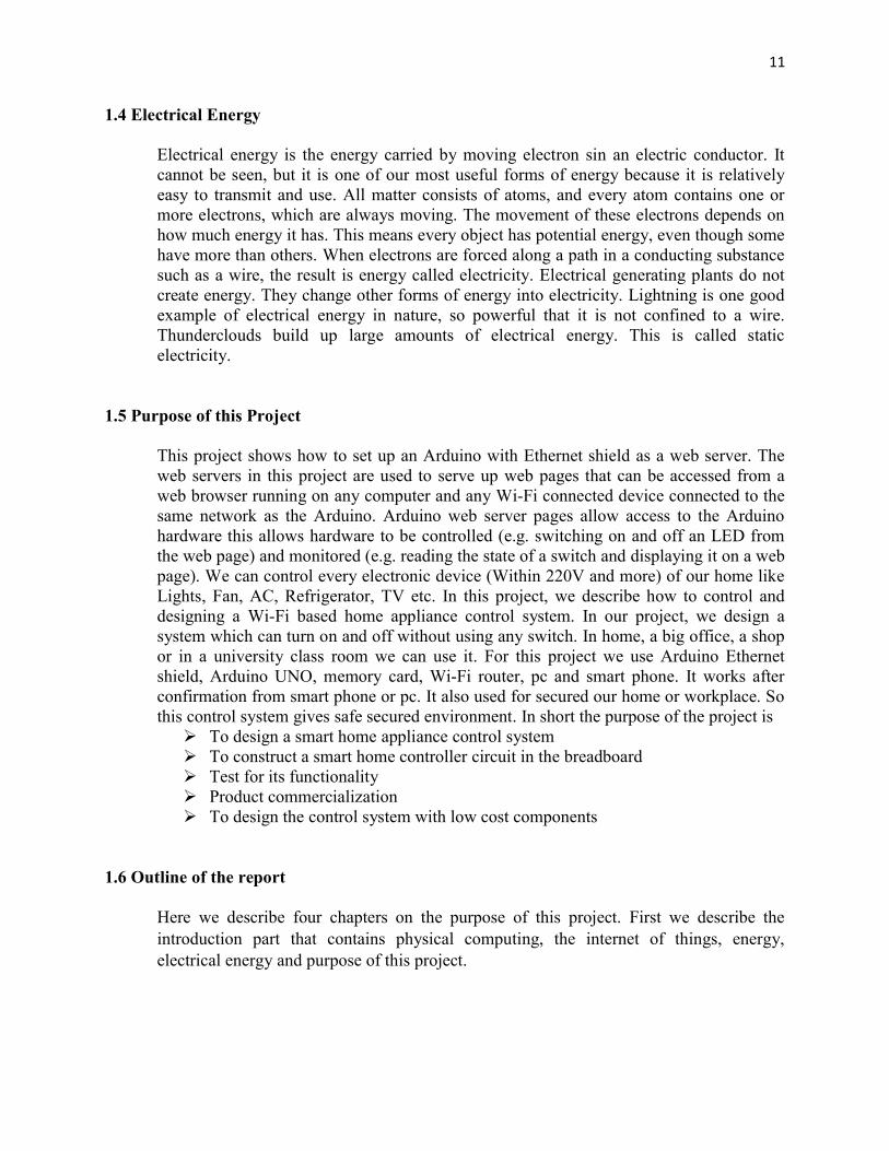
11 1.4 Electrical Energy
Electrical energy is the energy carried by moving electron sin an electric conductor. It cannot be seen, but it is one of our most useful forms of energy because it is relatively easy to transmit and use. All matter consists of atoms, and every atom contains one or more electrons, which are always moving. The movement of these electrons depends on how much energy it has. This means every object has potential energy, even though some have more than others. When electrons are forced along a path in a conducting substance such as a wire, the result is energy called electricity. Electrical generating plants do not create energy. They change other forms of energy into electricity. Lightning is one good example of electrical energy in nature, so powerful that it is not confined to a wire. Thunderclouds build up large amounts of electrical energy. This is called static electricity.
1.5 Purpose of this Project
This project shows how to set up an Arduino with Ethernet shield as a web server. The web servers in this project are used to serve up web pages that can be accessed from a web browser running on any computer and any Wi-Fi connected device connected to the same network as the Arduino. Arduino web server pages allow access to the Arduino hardware this allows hardware to be controlled (e.g. switching on and off an LED from the web page) and monitored (e.g. reading the state of a switch and displaying it on a web page). We can control every electronic device (Within 220V and more) of our home like Lights, Fan, AC, Refrigerator, TV etc. In this project, we describe how to control and designing a Wi-Fi based home appliance control system. In our project, we design a system which can turn on and off without using any switch. In home, a big office, a shop or in a university class room we can use it. For this project we use Arduino Ethernet shield, Arduino UNO, memory card, Wi-Fi router, pc and smart phone. It works after confirmation from smart phone or pc. It also used for secured our home or workplace. So this control system gives safe secured environment. In short the purpose of the project is To design a smart home appliance control system To construct a smart home controller circuit in the breadboard Test for its functionality Product commercialization To design the control system with low cost components
1.6 Outline of the report
Here we describe four chapters on the purpose of this project. First we describe the introduction part that contains physical computing, the internet of things, energy, electrical energy and purpose of this project.

12 Chapter 2
AN OVERVIEW OF MICROCONTROLLERS
2.1 Introduction
Arduino is an open source electronics platform based on easy-to-use hardware and software. In this project we use Arduino-UNO board. The Arduino hardware platform already has the power and reset circuitry setup as well as circuitry to program and communicate with the microcontroller over USB. In addition, the I/O pins of the microcontroller are typically already fed out to sockets/headers for easy access. On the software side, Arduino provides a number of libraries to make programming the microcontroller easier. The simplest of these are functions to control and read the I/O pins rather than having to fiddle with the bus/bit masks normally used to interface with the At mega I/O.
2.2 Microcontroller
A microcontroller is a small computer on a single integrated circuit containing a processor core, memory and programmable input/output peripherals. It is highly integrated chip that contains all the components comprising a controller. Microcontrollers are used in automatically controlled products and devices, such as automobile engine control systems, remote controls, office machines, implantable medical devices, appliance and other embedded systems. We used here for appliance cases.
2.3 Advantages of Microcontroller
The simplest computer processor is used as the "brain" of the future system. Single purposes and low power consumption. Depending on the taste of the manufacturer, a bit of memory, a few A/D
converters, input/output lines etc. are added. Low cost and small packaging. Simple software able to control it all and which everyone can easily learn about
has been developed.

13 2.4 Arduino-UNO
Arduino is an open-source electronics prototyping platform based on flexible, easy-to-use Hardware and software. Arduino consists of both a physical programmable circuit board and a piece of software, or IDE (Integrated Development Environment) that runs on your computer, used to write and upload computer code to the physical board. The Arduino platform has become quite popular with people just starting out with electronics, and for good reason. Unlike most previous programmable circuit boards, the Arduino does not need a separate piece of hardware in order to load new code onto the board – simply use a USB cable. Finally, Arduino provides a standard form factor that breaks out the functions of the micro-controller into a more accessible package. The Arduino software is free, the hardware boards are pretty cheap, and both the software and hardware are easy to learn has led to a large community of users who have contributed code and released instructions for a huge variety of Arduino-based projects.
2.5 Figure of Arduino-UNO
2.1 Figure: Arduino-UNO

14 2.6 History of Arduino-UNO
The Arduino is developed in 2005. The Arduino microcontroller was initially created as an educational platform for a class project at the Interaction Design Institute Ivrea in Milan (Italy) in 2005. It derived from a previous work of the Wiring microcontroller designed by Hernando Barragan in 2004. From the beginning, the Arduino board was developed to attract artists and designers. The Wiring microcontroller was created by Hernando Barragan to be used for parsing data to electronic devices. His aim was that it could be used by non-technical people who only had basic experience with using computers. He first of all wanted it to be used as a prototyping tool. Since he needed help to create an easy software tool to programmed the board he engaged Casey Reas and Massimo Banzi as his assistants. Reas created the visual programming language for the prototyping tool.
2.7 Development
The computer, commonly defined as a tool for processing, storing, and displaying information, arose from a long line of analog devices used for effective counting and calculation, ranging from the simple abacus (first invented in Sumeria around 2300 BC), to Napierʼs Bones (conceived in 1617, and the precursor to the slide rule), to BlaisePascalʼs gear-based mechanical calculator (1645).The development of the computer accelerated during the 1940ʼs, spurred on largely by the highly industrialized nature of military production in World War II.The 1960ʼs marked a significant evolutionary leap for computing, due to the development of solid state computers (such as the IBM 1401), which used transistors for processing operations, and magnetic core memory for storage. The invention of integrated circuits in 1959 by Jack Kilby, which enabled transistors and circuits to be fused onto small chips of semiconducting materials (such as silicon), allowed further miniaturization of computer components. Another important development during this decade was the advent of high-level computer programming languages that were written in symbolic language, making computer code somewhat easier to read and learn than previous machine languages. COBOL and FORTRAN were the main languages introduced during this period. The microprocessor was introduced in 1970. The microprocessor essentially miniaturized all hardware components of a computers central processing unit to fit onto a single, tiny integrated circuit, now more popularly known as a microchip. The microchip also became the main driving component of microcontrollers (such as the Arduino), which generally consist of a microchip, memory storage hardware, and input/ output hardware for sensors. The 1970ʼs and 1980ʻs also saw the development of a new generation of more powerful programming languages (such as C, C++, and later Java) for applications in business and science.

15 2.8 Evoluation
The PIC microcontroller board, introduced in 1985 by General Instruments, became one of the most popular tools for electronics enthusiasts (before the Arduino) for several reasons. Other popular boards for hobbyists include the BASIC Stamp (Parallax Inc., 1990), and Wiring both of which share the benefits of simplicity of programming, and a resulting ease of rapid-prototyping. The Arduino project grew largely out of the “DIY” climate created by the burgeoning popularity of rapid- prototyping boards like PIC. In fact, the immediate precursor to the Arduino was a custom made Wiring microcontroller created by the artist/ designer Hernando Barragan in 2004 for his. In 2005, the Arduino team was formed in Ivrea, Italy, consisting of Barragan, Massimo Banzi, David Cuartielles, Dave Mellis, Gianluca Marino, and Nicholas Zambetti. As a result, the Arduino incorporated the following characteristic, a programming environment based on processing language (a programming language conceived by Ben Fry and Casey Reas, also conceived for artists/ designers), the ability to program the board via a standard USB connection, and a low price point. The Arduino achieved rapid success even within its first two years of existence, selling in a quantity of more than 50,000 boards. By 2009, it had spawned over 13 different incarnations, each specialized for different applications. Today, the Arduino microcontroller has become one of the most popular prototyping platforms in the world, and is a prime example of how hardware and software technologies originally created for military, business, and scientific applications can be repurposed to serve the needs of individuals creating projects in the realms of new media art and design[1].
16 Chapter 3
THEORY BEHIND THE PROJECT
3.1 Introduction
This project includes Arduino Uno broad, Arduino Ethernet Shield, Relay, Wi-Fi Router, Ethernet cable, RJ45 connector. We want to connect the Arduino Ethernet Shield to an Arduino. We developed the connection by using upper equipments. At first we developed a connection without load. Then we developed the circuit with 220V power load.
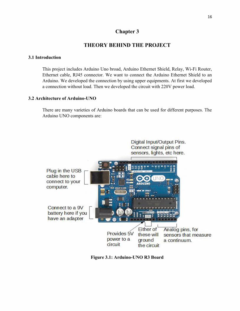
3.2 Architecture of Arduino-UNO
There are many varieties of Arduino boards that can be used for different purposes. The Arduino UNO components are:
Figure 3.1: Arduino-UNO R3 Board

17 3.2.1 Power
The Arduino/Genuino Uno board can be powered via the USB connection or with an external power supply. The power source is selected automatically. External (non-USB) power can come either from an AC-to-DC adapter (wall-wart) or battery. The adapter can be connected by plugging a 2.1mm center-positive plug into the board's power jack. Leads from a battery can be inserted in the GND and Vin pin headers of the POWER connector. The board can operate on an external supply from 6 to 20 volts. If supplied with less than 7V, however, the 5V pin may supply less than five volts and the board may become unstable. If using more than 12V, the voltage regulator may overheat and damage the board. The recommended range is 7 to 12 volts. The power pins are as follows: Vin. The input voltage to the Arduino/Genuino board when it's using an external
power source (as opposed to 5 volts from the USB connection or other regulated power source). You can supply voltage through this pin, or, if supplying voltage via the power jack, access it through this pin.
5V.This pin outputs a regulated 5V from the regulator on the board. The board can be supplied with power either from the DC power jack (7 - 12V), the USB connector (5V), or the VIN pin of the board (7-12V). Supplying voltage via the 5V or 3.3V pins bypasses the regulator, and can damage your board. We don't advise it.
3V3. A 3.3 volt supply generated by the on-board regulator. Maximum current draw is 50 mA.
GND. Ground pins. IOREF. This pin on the Arduino/Genuino board provides the voltage reference
with which the microcontroller operates. A properly configured shield can read the IOREF pin voltage and select the appropriate power source or enable voltage translators on the outputs to work with the 5V or 3.3V.
3.2.2 Memory
The ATmega328 has 32 KB (with 0.5 KB occupied by the boot loader). It also has 2 KB of SRAM and 1 KB of EEPROM (which can be read and written with the EEPROM library).

18 3.2.3 Input and Output
Each of the 14 digital pins on the Uno can be used as an input or output, using pinMode(), digitalWrite(), and digitalRead() functions. They operate at 5 volts. Each pin can provide or receive 20 mA as recommended operating condition and has an internal pull-up resistor (disconnected by default) of 20-50k ohm. A maximum of 40mA is the value that must not be exceeded on any I/O pin to avoid permanent damage to the microcontroller. In addition, some pins have specialized functions: Serial: 0 (RX) and 1 (TX). Used to receive (RX) and transmit (TX) TTL serial
data. These pins are connected to the corresponding pins of the ATmega8U2 USB-to-TTL Serial chip.
External Interrupts: 2 and 3. These pins can be configured to trigger an interrupt on a low value, a rising or falling edge, or a change in value. See the attachInterrupt() function for details.
PWM: 3, 5, 6, 9, 10, and 11. Provide 8-bit PWM output with the analogWrite() function.
SPI: 10 (SS), 11 (MOSI), 12 (MISO), 13 (SCK). These pins support SPI communication using the SPI library.
LED: 13. There is a built-in LED driven by digital pin 13. When the pin is HIGH value, the LED is on, when the pin is LOW, it's off.
TWI: A4 or SDA pin and A5 or SCL pin. Support TWI communication using the Wire library.
The Uno has 6 analog inputs, labeled A0 through A5, each of which provide 10 bits of resolution (i.e. 1024 different values). By default they measure from ground to 5 volts, though is it possible to change the upper end of their range using the AREF pin and the analogReference() function.
3.2.4 Power LED Indicator
Just beneath and to the right of the word “UNO” on circuit board, there’s a tiny LED next to the word ‘ON’. This LED should light up whenever plug Arduino into a power source. If this light doesn’t turn on, there’s a good chance something is wrong.

19 3.2.5 Reset Button
The Arduino has a reset button. Pushing it will temporarily connect the reset pin to ground and restart any code that is loaded on the Arduino. This can be very useful if code doesn’t repeat, but we want to test it multiple times. Unlike the original Nintendo however, blowing on the Arduino doesn’t usually fix any problems.
3.2.6 TX RX LEDs
TX is short for transmit, RX is short for receive. In our case, there are two places on the Arduino UNO where TX and RX appear once by digital pins 0 and 1, and a second time next to the TX and RX indicator LEDs. These LEDs will give us some nice visual indications whenever Arduino is receiving or transmitting data.
3.2.7 Main IC
The black thing with all the metal legs is an IC, or Integrated Circuit. The main IC on the Arduino is slightly different from board type to board type, but is usually from the AT mega line of IC’s from the ATMEL Company. This can be important, as may need to know the IC type before loading up a new program from the Arduino software. This information can usually be found in writing on the top side of the IC.
3.2.8 Voltage Regulator
The voltage regulator is not actually something interacting with on the Arduino. But it is potentially useful to know that it is there and what it’s for. It controls the amount of voltage that is let into the Arduino board. It will turn away an extra voltage that might harm the circuit.
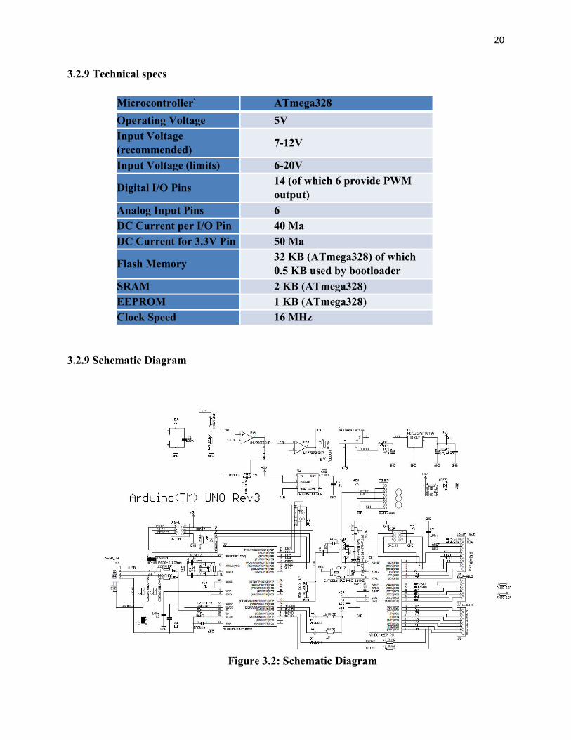
20 3.2.9 Technical specs
Microcontroller` ATmega328 Operating Voltage 5V Input Voltage (recommended) 7-12V Input Voltage (limits) 6-20V Digital I/O Pins 14 (of which 6 provide PWM
output) Analog Input Pins 6 DC Current per I/O Pin 40 Ma DC Current for 3.3V Pin 50 Ma Flash Memory 32 KB (ATmega328) of which
0.5 KB used by bootloader SRAM 2 KB (ATmega328) EEPROM 1 KB (ATmega328) Clock Speed 16 MHz
3.2.9 Schematic Diagram
Figure 3.2: Schematic Diagram

21 3.3 Getting started with Arduino Software
First download and install the Arduino for Mac, Linux or Windows from arduino.cc. Windows users also need to install a driver. Connect your board via USB, launch the Arduino application and select Arduino-Uno from the tools to board menu. Open the sketch File. Examples: 01. Basics: Blink. Click the toolbar button to upload it to your board.
3.3.1 The Integrated Development Environment (IDE)
Every microcontroller needs software to be programmed. The Arduino board is not a case apart. It has its own integrated development environment (IDE).It is free and everyone can download it from its official website using either the Windows, Mac OS X or Linux platform. That allows Arduino Board to gain more users and it also helps it to grow.
3.3.2 IDE Parts
Compile: Before program “code” can be sent to the board, it needs to be converted into instructions that the board understands. This process is called Compiling.
Stop: This stops the compilation process. Create new Sketch: This opens a new window to create news ketch. Open Existing Sketch: This loads a sketch from a file on our computer. Save Sketch: This saves the changes to the sketch. Upload to Board: This compiles and then transmits over the USB cable to our
board. Serial Monitor: Until this point when our programs (sketches) didn’t work, we
just pulled out our hair and tried harder. Tab Button: This lets you create multiple files in your sketch. This is for more
advanced programming than we will do in this class. Sketch Editor: This is where write or edit sketches Text Console: This shows you what the IDE is currently doing and is also where
error messages display if make a mistake in typing program. Line Number: This shows what line number your cursor is on.
22 3.4 Arduino Ethernet Shield
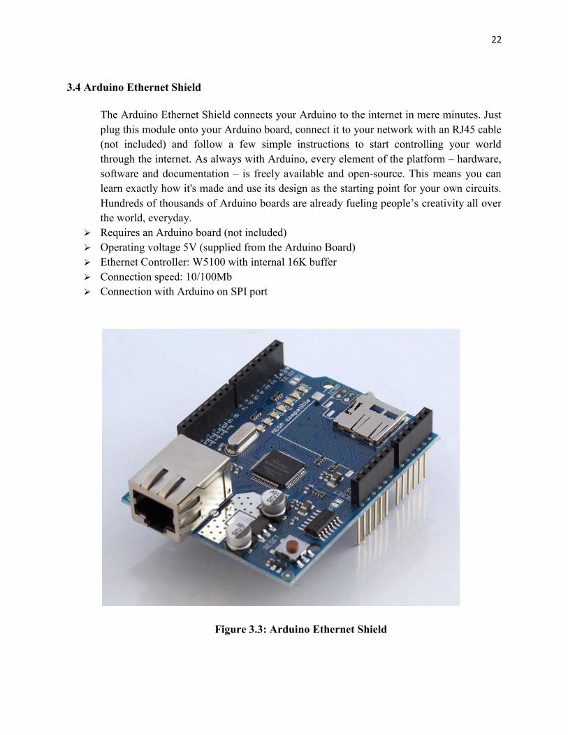
The Arduino Ethernet Shield connects your Arduino to the internet in mere minutes. Just plug this module onto your Arduino board, connect it to your network with an RJ45 cable (not included) and follow a few simple instructions to start controlling your world through the internet. As always with Arduino, every element of the platform – hardware, software and documentation – is freely available and open-source. This means you can learn exactly how it's made and use its design as the starting point for your own circuits. Hundreds of thousands of Arduino boards are already fueling people’s creativity all over the world, everyday.
Requires an Arduino board (not included) Operating voltage 5V (supplied from the Arduino Board) Ethernet Controller: W5100 with internal 16K buffer Connection speed: 10/100Mb Connection with Arduino on SPI port
Figure 3.3: Arduino Ethernet Shield
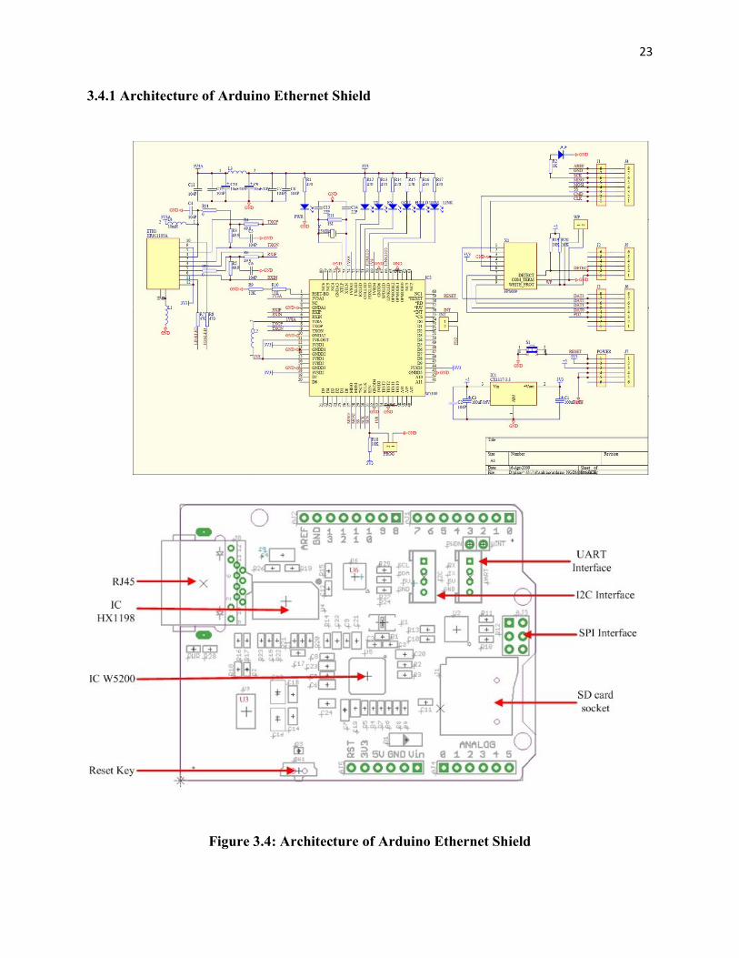
23 3.4.1 Architecture of Arduino Ethernet Shield
Figure 3.4: Architecture of Arduino Ethernet Shield

24 3.4.2 Description
The Arduino Ethernet Shield allows an Arduino board to connect to the internet. It is based on the Wiznet W5100ethernet chip (datasheet). The Wiznet W5100 provides a network (IP) stack capable of both TCP and UDP. It supports up to four simultaneous socket connections. Use the Ethernet library to write sketches which connect to the internet using the shield. The ethernet shield connects to an Arduino board using long wire-wrap headers which extend through the shield. This keeps the pin layout intact and allows another shield to be stacked on top. The most recent revision of the board exposes the 1.0 pinout on rev 3 of the Arduino UNO board. The Ethernet Shield has a standard RJ-45 connection, with an integrated line transformer and Power over Ethernet enabled. There is an onboard micro-SD card slot, which can be used to store files for serving over the network. It is compatible with the Arduino Uno and Mega (using the Ethernet library). The onboard microSD card reader is accessible through the SD Library. When working with this library, SS is on Pin 4. The original revision of the shield contained a full-size SD card slot; this is not supported. The shield also includes a reset controller, to ensure that the W5100 Ethernet module is properly reset on power-up. Previous revisions of the shield were not compatible with the Mega and need to be manually reset after power-up. The current shield has a Power over Ethernet (PoE) module designed to extract power from a conventional twisted pair Category 5 Ethernet cable:
IEEE802.3af compliant Low output ripple and noise (100mVpp) Input voltage range 36V to 57V Overload and short-circuit protection 9V Output
High efficiency DC/DC converter: typ 75% @ 50% load 1500V isolation (input to output)
Arduino communicates with both the W5100 and SD card using the SPI bus (through the ICSP header). This is on digital pins 10, 11, 12, and 13 on the Uno and pins 50, 51, and 52 on the Mega. On both boards, pin 10 is used to select the W5100 and pin 4 for the SD card. These pins cannot be used for general I/O. On the Mega, the hardware SS pin, 53, is not used to select either the W5100 or the SD card, but it must be kept as an output or the SPI interface won't work. Note that because the W5100 and SD card share the SPI bus, only one can be active at a time. If you are using both peripherals in your program, this should be taken care of by the corresponding libraries. If you're not using one of the peripherals in your program, however, you'll need to explicitly deselect it. To do this with the SD card, set pin 4 as an output and write a high to it. For the W5100, set digital pin 10 as a high output. The shield provides a standard RJ45 ethernet jack. The reset button on the shield resets both the W5100 and the Arduino board. The shield contains a number of informational LEDs:
25 PWR: indicates that the board and shield are powered LINK: indicates the presence of a network link and flashes when the shield transmits or
receives data FULLD: indicates that the network connection is full duplex 100M: indicates the presence of a 100 Mb/s network connection (as opposed to 10 Mb/s) RX: flashes when the shield receives data TX: flashes when the shield sends data COLL: flashes when network collisions are detected
3.4.3 Connecting the Shield
To use the shield, mount it on top of an Arduino board (e.g. the Uno). To upload sketches to the board, connect it to your computer with a USB cable as you normally would. Once the sketch has been uploaded, you can disconnect the board from your computer and power it with an external power supply.Connect the shield to your computer or a network hub or router using a standard ethernet cable (CAT5 or CAT6 withRJ45 connectors). Connecting to a computer may require the use of a cross-over cable (although many computers, including all recent Macs can do the cross-over internally).
3.4.4 Network Settings
The shield must be assigned a MAC address and a fixed IP address using the Ethernet.begin() function. A MAC address is a globally unique identifier for a particular device. Current Ethernet shields come with a sticker indicating the MAC address you should use with them. For older shields without a dedicated MAC address, inventing a random one should work, but don't use the same one for multiple boards. Valid IP addresses depend on the configuration of your network. It is possible to use DHCP to dynamically assign an IP to the shield. Optionally, you can also specify a network gateway and subnet.
3.4.5 SD Card The latest revision of the Ethernet Shield includes a micro-SD card slot, which can be interfaced with using the SD library.
26 3.5 Liquid Crystal Display (LCD) LCD (Liquid Crystal Display) screen is an electronic display module and find a wide
range of applications. A 16x2 LCD display is very basic module and is very commonly used in various devices and circuits. These modules are preferred over seven segments and other multi segment LEDs. The reasons being: LCDs are economical; easily programmable; have no limitation of displaying special & even custom characters (unlike in seven segments), animations and so on. A 16x2 LCD means it can display 16 characters per line and there are 2 such lines. In this LCD each character is displayed in 5x7 pixel matrix. This LCD has two registers, namely, Command and Data. The command register stores the command instructions given to the LCD. A command is an instruction given to LCD to do a predefined task like initializing it, clearing its screen, setting the cursor position, controlling display etc. The data register stores the data to be displayed on the LCD. The data is the ASCII value of the character to be displayed on the LCD
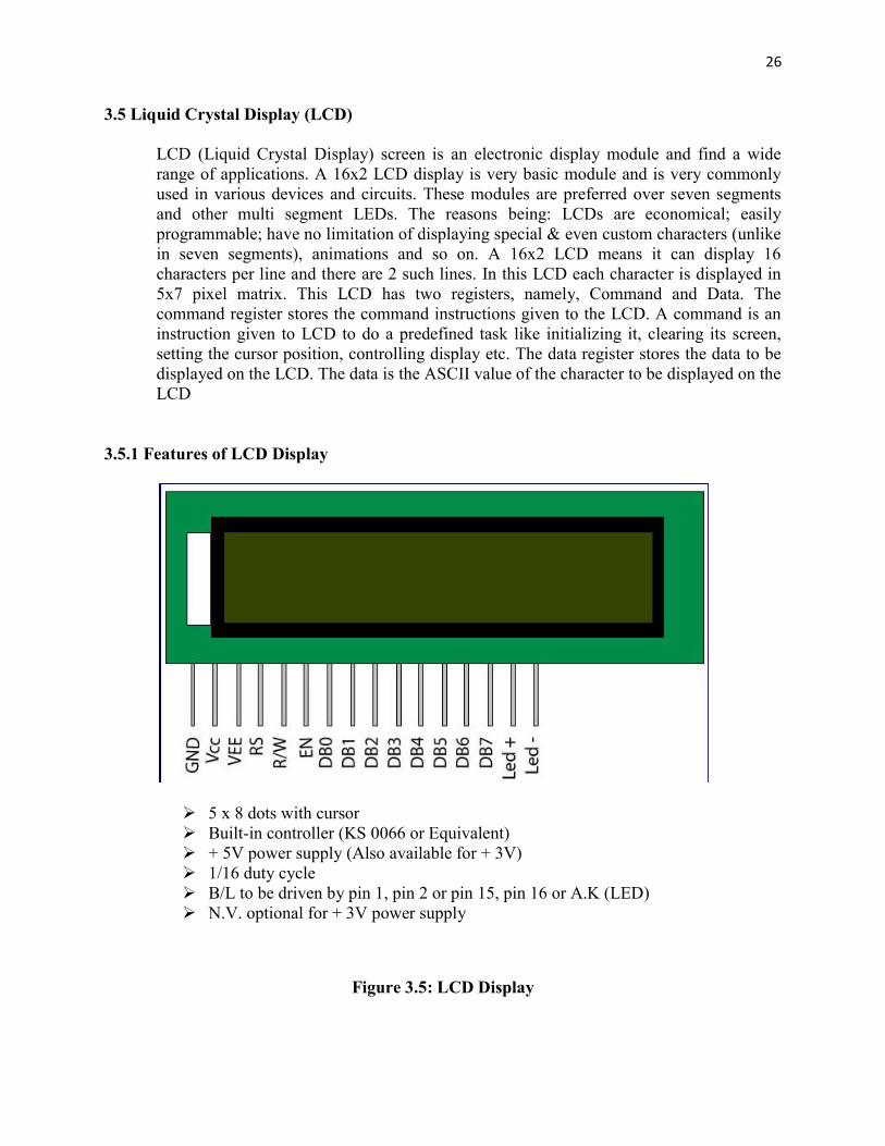
3.5.1 Features of LCD Display
5 x 8 dots with cursor Built-in controller (KS 0066 or Equivalent) + 5V power supply (Also available for + 3V) 1/16 duty cycle B/L to be driven by pin 1, pin 2 or pin 15, pin 16 or A.K (LED) N.V. optional for + 3V power supply
Figure 3.5: LCD Display

27 3.6 What is a relay
A Relay is an electrically operated switch. Many relays use an electromagnet to mechanically operate the switch and provide electrical isolation between two circuits. In this project there is no real need to isolate one circuit from the other, but we will use an Arduino UNO to control the relay. We will develop a simple circuit to demonstrate and distinguish between the NO (Normally open) and NC (Normally closed) terminals of the relay. We will then use the information gained in this tutorial to make a much more exciting circuit. But we have to start somewhere. So let's get on with it.
3.6.1 Parts Required Freetronics Eleven or (Arduino UNO compatible board) 4 Channel Relay Module 2x LEDs 2x 330 ohm resistors Jumper Wires (male to male) Jumper Wires (female to male)
3.6.3 Circuit Diagram of Relay
Figure 3.6: Circuit Diagram of Relay

3.6.2 Arduino Connected Reley
Figure 3.7: 3.6.4 Table of Connections
Arduino Connected Reley Module
3.7: Arduino Connected Reley Module
28

29 3.7 Wi-Fi
Wi-Fi is the name of a popular wireless networking technology that uses radio waves to provide wireless high-speed Internet and network connections. A common misconception is that the term Wi-Fi is short for "wireless fidelity," however this is not the case. Wi-Fi is simply a trademarked phrase that means IEEE 802.11x.
3.7.1 The Wi-Fi Alliance
The Wi-Fi Alliance, the organization that owns the Wi-Fi registered trademark term specifically defines Wi-Fi as any "wireless local area network (WLAN) products that are based on the Institute of Electrical and Electronics Engineers' (IEEE) 802.11 standards." Initially, Wi-Fi was used in place of only the 2.4GHz 802.11b standard, however the Wi-Fi Alliance has expanded the generic use of the Wi-Fi term to include any type of network or WLAN product based on any of the 802.11 standards, including 802.11b, 802.11a, dual-band, and so on, in an attempt to stop confusion about wireless LAN interoperability.
3.7.2 Wi-Fi Support
Wi-Fi is supported by many applications and devices including video game consoles, home networks, PDAs, mobile phones, major operating systems, and other types of consumer electronics. Any products that are tested and approved as "Wi-Fi Certified" (a registered trademark) by the Wi-Fi Alliance are certified as interoperable with each other, even if they are from different manufacturers. For example, a user with a Wi-Fi Certified product can use any brand of access point with any other brand of client hardware that also is also "Wi-Fi Certified". Products that pass this certification are required to carry an identifying seal on their packaging that states "Wi-Fi Certified" and indicates the radio frequency band used (2.5GHz for 802.11b, 802.11g, or 802.11n, and 5GHz for802.11a).

30 3.7.3 How it works
A wireless network or Wireless Local Area Network (WLAN) serves the same purpose as a wired one — to link a group of computers. Because "wireless" doesn't require costly wiring, the main benefit is that it's generally easier, faster and cheaper to set up. By comparison, creating a network by pulling wires throughout the walls and ceilings of an office can be labor-intensive and thus expensive. But even when you have a wired network already in place, a wireless network can be a cost-effective way to expand or augment it. In fact, there's really no such thing as a purely wireless network, because most link back to a wired network at some point. The Basics Wireless networks operate using radio frequency (RF) technology, a frequency within the electromagnetic spectrum associated with radio wave propagation. When an RF current is supplied to an antenna, an electromagnetic field is created that then is able to propagate through space. The cornerstone of a wireless network is a device known as an access point (AP). The primary job of an access point is to broadcast a wireless signal that computers can detect and "tune" into. Since wireless networks are usually connected to wired ones, an access point also often serves as a link to the resources available on the a wired network, such as an Internet connection. In order to connect to an access point and join a wireless network, computers must be equipped with wireless network adapters. These are often built right into the computer, but if not, just about any computer or notebook can be made wireless-capable through the use of an add-on adapter plugged into an empty expansion slot, USB port, or in the case of notebooks, a PC Card slot.
3.7.4 Wireless Speed & Range
When you buy a piece of wireless network hardware, it will often quote performance figures (i.e., how fast it can transmit data) based on the type of wireless networking standard it uses, plus any added technological enhancements. In truth, these performance figures are almost always wildly optimistic. While the official speeds of 802.11b, 802.11g and 802.11n networks are 11, 54, and 270 megabits per second (Mbps) respectively, these figures represent a scenario that simply not attainable in the real world. As a general rule, you should assume that in a best-case scenario you will get roughly one-third of the advertised performance. It's also worth noting that a wireless network is by definition a shared network, so the more computers you have connected to a wireless access point the less data each will be able to send and receive. Just as a wireless network's speed can vary greatly, so too can the range. For example, 802.11b and g officially work over a distance of up to 328 feet indoors or 1,312 feet outdoors, but the key term there is "up to". Chances are you won't see anywhere close to those

31 numbers. As you might expect, the closer you are to an access point, the stronger the signal and the faster the connection speed. The range and speed you get out of wireless network will also depend on the kind of environment in which it operates. And that brings us to the subject of interference.
3.8 Wireless Access Points or ( WAPs )
Wireless access points (APs or WAPs) are special-purpose communication devices on wireless local area networks (WLANs). Access points act as a central transmitter and receiver of wireless radio signals. Mainstream wireless APs support Wi-Fi and are most commonly used to support public Internet hotspots and other business networks where larger buildings and spaces need wireless coverage. Access points are small hardware devices closely resembling home broadband routers. (Home routers actually integrate an access point into the rest of the device.) AP hardware consists of radio transceivers, antennas and device firmware. Access points enable so-called Wi-Fi infrastructure mode networking. Although Wi-Fi connections do not technically require the use of access points, APs enable Wi-Fi networks to scale to larger distances and numbers of clients. Modern access points support up to 255 clients (while very old ones supported only about 20). APs also provide bridging capability that enables a Wi-Fi network to connect to other wired networks.
Figure 3.8: 8 Wireless Access Points

32 Chapter 4
SYSTEM DESIGN AND ANALYSIS
4.1 Introduction
In this project helps those people who interested to build something with Arduino. To Design a project include into two parts, one is hardware design and another part is software design. We use Arduino Ethernet Shield, Relay module for the hardware design and we connected these components with microcontroller. Arduino software is downloaded from www.arduino.cc and C/C++ programmable language is used. Many examples are given in the ardiono.cc and this software is easy to usage.
4.2 Hardware Design
The whole system design is divided into two parts to design a smart home appliance control system. One is the design the smart system in the breadboard and controls the designed system. Another part is the display part design to count the value in smart system. Finally, the smart home appliance control system is formed a complete integrated system. In this project Arduino development board is more efficient.
4.2.1 Block Diagram of the control system
Figure 4.1: Block Diagram of the control system
Mobile Phone or PC with a WEB Browser and Wi-Fi enable
Wi-Fi access point that connected to the Ethernet Shield
Ethernet Shield and Arduino UNO R3 Board
Relay Module That connected to the both Arduino UNO and AC load
AC Load Light Bulb, Switch, Fan etc

33 4.2.2 Equipments Used in this System
To design the project we use following component: One Arduino Uno Board. One bread board. One Arduino Ethernet Shield. One TP-link Wireless Access point. RJ-45 Connector. UTP Cable. FourLED. Four Relay & 12V power supply. 1k & 2k Resistance. One table fan. Three 100W bulb light.
4.2.3 Full Circuit Design
Here we have shown connection that we have done in this project.
Figure 4.2: Full Circuit Design

34 4.2.4 Connecting the Arduino Ethernet Shield
Setting it up is as simple as plugging the header pins from the shield into your Arduino.
Figure 4.3: Connection of Arduino Ethernet Shield
4.2.5 Connection of Arduino Ethernet Shield with Wi-Fi access point
We also developed a connection of Arduino Ethernet Shield with Wi-Fi access point using RJ-45 connector and UTP cable. Plug the Arduino into computer's USB port and the Ethernet shield into Wi-Fi access point like the figure.
Figure 4.4: Connection of Arduino Ethernet Shield with Wi-Fi access point

35 4.2.6 Connection to Load with Power Source
We use 12V Relay for connect a light or electricity supply of a room. The main operation of a relay comes in places where only a low-power signal can be used to control a circuit. It is also used in places where only one signal can be used to control a lot of circuits. The high end applications of relays require high power to be driven by electric motors.
Figure 4.5: Connection to Load with Power Source

36 Relays are called contactors. We connect Arduino pin 13 with transistor’s base. The emitter is connected to ground and the collector is connected to relay and diode. The relay and diode are connected parallels. The two terminals of a relay operate as a switch. When the contacts are in contact then the current flows from Terminal to Terminal. There are two types of contacts, the NO and the NC. NO stands for Normal Open contact, while NC stands for Normal Closed contact. The Normal Open is a contact like the one showed in the previous illustration. When the contacts are still, then no current flows through it (because it is an OPEN circuit). On the other hand, a Normal Closed contact allows the current to flow when the contact is still. The NC contact is turned upside-down compared to the NO contact. This way, both contacts (NO and NC) will change state if a force is applied to the left metal heading from UP to DOWN. The device that forces the terminal to move is actually an electromagnet. A coil is placed right under the contact. When current is flown through this coil, magnetism is created. This magnetism can overcome the force of the spring and can pull the contact towards it, thus it changes its position. And due to the fact that the contact is usually a small piece of metal not capable to be pulled by the electromagnet, another piece of metal is attached to the common. The other side of relay is connected to bulb or electricity supply of a room. We need 12V power supply for relay.

37 4.3 Software Design
Software design is divided into two parts. First we write the Arduino program in Arduino software. Then we compile it to the Arduino hardware. This Arduino command is control the Arduino hardware and other circuit connection. For making connection between Arduino and Wi-Fi enable device we need to install Arduino SD card that host a web page that displays to the browser.
4.3.1 Installing Arduino
Arduino runs on Windows. Go to the Arduino software web site at http://arduino.cc/en/Main/Software and download the version of the software compatible with our system. We use Arduino 1.0.5 version.
4.3.2 Verifying the Hardware
Now that we have the Arduino IDE software installed, let’s connect the computer to the Arduino board, load a small program, and verify that all components are working together. First, need to connect the USB cable to our mc board and then plug the other end of the USB cable into our computer.
4.3.3 Arduino Language
The Arduino language is implemented in C/C++ and based in Wiring. When we write an Arduino sketch, we are implicitly making use of the Wiring library, which is included with the Arduino IDE. This allows us to make run able programs by using only two functions: setup () and loop (). As mentioned, the Wiring language is inspired by Processing, and the Arduino language structure is inherited from the Processing language, where the equivalent functions are called setup (). We need to include both functions in every Arduino program, even if we don’t need one of them. Let’s analyze the structure of a simple Arduino sketch using again the Blink example.
4.3.4 SD Card Web Server I/O
In this project HTML, JavaScript, CSS, HTTP, Ajax and the SD card are used to make a web page that displays Arduino analog and digital inputs and allows digital outputs to be controlled. The Arduino web server hosts a web page that displays four analog input
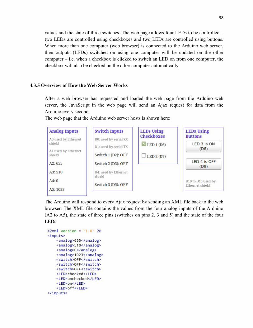
38 values and the state of three switches. The web page allows four LEDs to be controlled – two LEDs are controlled using checkboxes and two LEDs are controlled using buttons. When more than one computer (web browser) is connected to the Arduino web server, then outputs (LEDs) switched on using one computer will be updated on the other computer – i.e. when a checkbox is clicked to switch an LED on from one computer, the checkbox will also be checked on the other computer automatically.
4.3.5 Overview of How the Web Server Works
After a web browser has requested and loaded the web page from the Arduino web server, the JavaScript in the web page will send an Ajax request for data from the Arduino every second. The web page that the Arduino web server hosts is shown here:
The Arduino will respond to every Ajax request by sending an XML file back to the web browser. The XML file contains the values from the four analog inputs of the Arduino (A2 to A5), the state of three pins (switches on pins 2, 3 and 5) and the state of the four LEDs.

39 XML File Sent by Arduino When an LED is switched on from the web page by checking a checkbox, the JavaScript will send the state of the checkbox (send an instruction to switch the LED on) with the next Ajax request. The same will occur if the LED is switched off or if one of the buttons is used to switch an LED on or off.
4.3.6 Source Code
The source code for both the Arduino sketch and web page are a bit big to include on this page. It will show in Appendix.
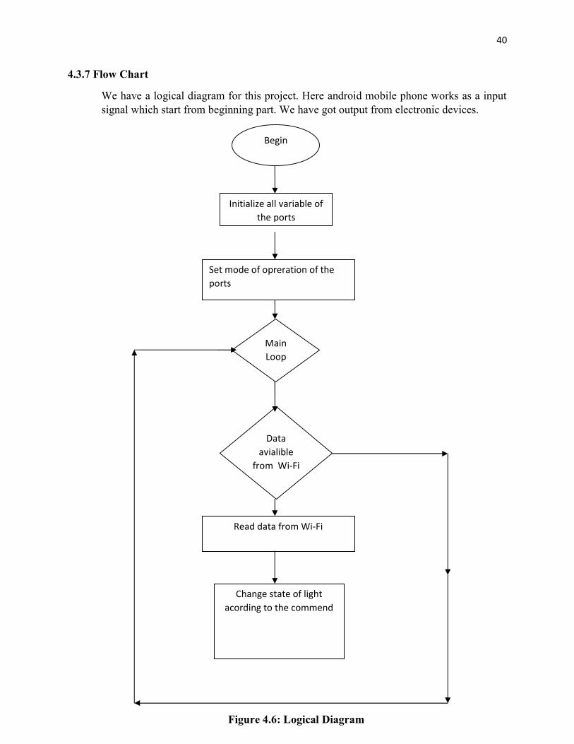
40 4.3.7 Flow Chart
We have a logical diagram for this project. Here android mobile phone works as a input signal which start from beginning part. We have got output from electronic devices.
Data avialible
from Wi-Fi
Begin
Initialize all variable of the ports
Set mode of opreration of the ports
Main Loop
Read data from Wi-Fi
Change state of light acording to the commend
Figure 4.6: Logical Diagram
41 Chapter 5
IMPLEMANTATION AND RESULT
5.1 Implementation
All the parts are connected as circuit design. Then we upload the programming code in the Arduino and we get positive result. It works properly according to our design
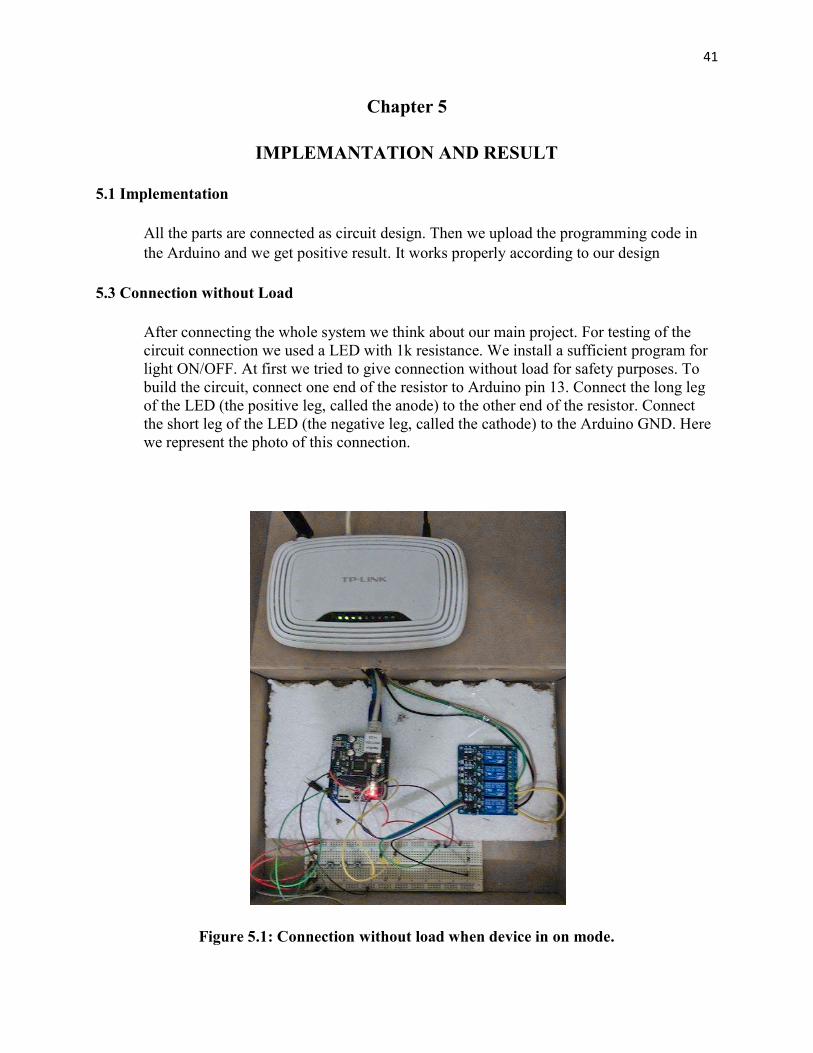
5.3 Connection without Load
After connecting the whole system we think about our main project. For testing of the circuit connection we used a LED with 1k resistance. We install a sufficient program for light ON/OFF. At first we tried to give connection without load for safety purposes. To build the circuit, connect one end of the resistor to Arduino pin 13. Connect the long leg of the LED (the positive leg, called the anode) to the other end of the resistor. Connect the short leg of the LED (the negative leg, called the cathode) to the Arduino GND. Here we represent the photo of this connection.
Figure 5.1: Connection without load when device in on mode.

42 5.4 Development of the Whole System with load
In this stage we developed the main connection of this project. We said as last part about without load connection of LED, now we discuss the load connection with fan, lights, AC, refrigerator etc. Here for AC load we use Arduino Relay Module. We also use some sensor for read the analog After all successful connection we will get output by controlling every device. We can control fan and lights by using Wi-Fi. Here we represent the photo of this connection.
Figure 5.2: Connection with load when device in OFF mode
Figure 5.3: Connection with load when device in ON mode

43 Chapter 6
CONCLUSION
6.1 Conclusion
The Home Appliance Control System Using Wi-Fi has been designed and developed for making our life more easy and secured. We use 5V from Arduino board and use 12V DC power supply for relay connection. We use the Arduino Ethernet shield and Wi-Fi technology. Finally, we have designed and developed the whole control system and tested using Mobile Phone. We fix all the problems encountered during the design and testing of the system. Finally, we successfully achieved our goals. In this study, the application of microcontroller with improved algorithm of extended specifications has increased the use of android mobile phone and improves the controlling the home appliances. The developed home appliance control system is efficient and the production cost is low. So, our Home Appliance Control System Using Wi-Fi is suitable for commercial use.
6.2 Future Work Scope We have used a small subset of each of these technologies. This project gives us an opportunity to do a big project in future. The applications stated above are some demo applications that are absolutely possible with its future development. Initially for the limitation of time and required fund we were able to develop just a Home Appliance Control System.

44 APPENDIX
1. Programming Code Arduino Scatch #include <SPI.h> #include <Ethernet.h> #include <SD.h> // size of buffer used to capture HTTP requests #define REQ_BUF_SZ 60 // MAC address from Ethernet shield sticker under board byte mac[] = { 0xDE, 0xAD, 0xBE, 0xEF, 0xFE, 0xED }; IPAddress ip(192, 168, 0, 115); // IP address, may need to change depending on network EthernetServer server(80); // create a server at port 80 File webFile; // the web page file on the SD card char HTTP_req[REQ_BUF_SZ] = {0}; // buffered HTTP request stored as null terminated string char req_index = 0; // index into HTTP_req buffer boolean LED_state[4] = {0}; // stores the states of the LEDs void setup() { // disable Ethernet chip pinMode(10, OUTPUT); digitalWrite(10, HIGH);

45 Serial.begin(9600); // for debugging // initialize SD card Serial.println("Initializing SD card..."); if (!SD.begin(4)) { Serial.println("ERROR - SD card initialization failed!"); return; // init failed } Serial.println("SUCCESS - SD card initialized."); // check for index.htm file if (!SD.exists("index.htm")) { Serial.println("ERROR - Can't find index.htm file!"); return; // can't find index file } Serial.println("SUCCESS - Found index.htm file."); // switches on pins 2, 3 and 5 pinMode(2, INPUT); pinMode(3, INPUT); pinMode(5, INPUT); // LEDs pinMode(6, OUTPUT); pinMode(7, OUTPUT); pinMode(8, OUTPUT); pinMode(9, OUTPUT);

46 Ethernet.begin(mac, ip); // initialize Ethernet device server.begin(); // start to listen for clients } void loop() { EthernetClient client = server.available(); // try to get client if (client) { // got client? boolean currentLineIsBlank = true; while (client.connected()) { if (client.available()) { // client data available to read char c = client.read(); // read 1 byte (character) from client // limit the size of the stored received HTTP request // buffer first part of HTTP request in HTTP_req array (string) // leave last element in array as 0 to null terminate string (REQ_BUF_SZ - 1) if (req_index < (REQ_BUF_SZ - 1)) { HTTP_req[req_index] = c; // save HTTP request character req_index++; } // last line of client request is blank and ends with \n // respond to client only after last line received if (c == '\n' && currentLineIsBlank) { // send a standard http response header
47 client.println("HTTP/1.1 200 OK"); // remainder of header follows below, depending on if // web page or XML page is requested // Ajax request - send XML file if (StrContains(HTTP_req, "ajax_inputs")) { // send rest of HTTP header client.println("Content-Type: text/xml"); client.println("Connection: keep-alive"); client.println(); SetLEDs(); // send XML file containing input states XML_response(client); } else { // web page request // send rest of HTTP header client.println("Content-Type: text/html"); client.println("Connection: keep-alive"); client.println(); // send web page webFile = SD.open("index.htm"); // open web page file if (webFile) { while(webFile.available()) { client.write(webFile.read()); // send web page to client } webFile.close();

48 } } // display received HTTP request on serial port Serial.print(HTTP_req); // reset buffer index and all buffer elements to 0 req_index = 0; StrClear(HTTP_req, REQ_BUF_SZ); break; } // every line of text received from the client ends with \r\n if (c == '\n') { // last character on line of received text // starting new line with next character read currentLineIsBlank = true; } else if (c != '\r') { // a text character was received from client currentLineIsBlank = false; } } // end if (client.available()) } // end while (client.connected()) delay(1); // give the web browser time to receive the data client.stop(); // close the connection } // end if (client) }

49 // checks if received HTTP request is switching on/off LEDs // also saves the state of the LEDs void SetLEDs(void) { // LED 1 (pin 6) if (StrContains(HTTP_req, "LED1=1")) { LED_state[0] = 1; // save LED state digitalWrite(6, HIGH); } else if (StrContains(HTTP_req, "LED1=0")) { LED_state[0] = 0; // save LED state digitalWrite(6, LOW); } // LED 2 (pin 7) if (StrContains(HTTP_req, "LED2=1")) { LED_state[1] = 1; // save LED state digitalWrite(7, HIGH); } else if (StrContains(HTTP_req, "LED2=0")) { LED_state[1] = 0; // save LED state digitalWrite(7, LOW); } // LED 3 (pin 8) if (StrContains(HTTP_req, "LED3=1")) {

50 LED_state[2] = 1; // save LED state digitalWrite(8, HIGH); } else if (StrContains(HTTP_req, "LED3=0")) { LED_state[2] = 0; // save LED state digitalWrite(8, LOW); } // LED 4 (pin 9) if (StrContains(HTTP_req, "LED4=1")) { LED_state[3] = 1; // save LED state digitalWrite(9, HIGH); } else if (StrContains(HTTP_req, "LED4=0")) { LED_state[3] = 0; // save LED state digitalWrite(9, LOW); } } // send the XML file with analog values, switch status // and LED status void XML_response(EthernetClient cl) { int analog_val; // stores value read from analog inputs int count; // used by 'for' loops int sw_arr[] = {2, 3, 5}; // pins interfaced to switches

51 cl.print("<?xml version = \"1.0\" ?>"); cl.print("<inputs>"); // read analog inputs for (count = 2; count <= 5; count++) { // A2 to A5 analog_val = analogRead(count); cl.print("<analog>"); cl.print(analog_val); cl.println("</analog>"); } // read switches for (count = 0; count < 3; count++) { cl.print("<switch>"); if (digitalRead(sw_arr[count])) { cl.print("ON"); } else { cl.print("OFF"); } cl.println("</switch>"); } // checkbox LED states // LED1 cl.print("<LED>"); if (LED_state[0]) {

52 cl.print("checked"); } else { cl.print("unchecked"); } cl.println("</LED>"); // LED2 cl.print("<LED>"); if (LED_state[1]) { cl.print("checked"); } else { cl.print("unchecked"); } cl.println("</LED>"); // button LED states // LED3 cl.print("<LED>"); if (LED_state[2]) { cl.print("on"); } else { cl.print("off"); } cl.println("</LED>");

53 // LED4 cl.print("<LED>"); if (LED_state[3]) { cl.print("on"); } else { cl.print("off"); } cl.println("</LED>"); cl.print("</inputs>"); } // sets every element of str to 0 (clears array) void StrClear(char *str, char length) { for (int i = 0; i < length; i++) { str[i] = 0; } } // searches for the string sfind in the string str // returns 1 if string found // returns 0 if string not found char StrContains(char *str, char *sfind)
54 { char found = 0; char index = 0; char len; len = strlen(str); if (strlen(sfind) > len) { return 0; } while (index < len) { if (str[index] == sfind[found]) { found++; if (strlen(sfind) == found) { return 1; } } else { found = 0; } index++; } return 0; }

55 2. SD Card WEB page Code <!DOCTYPE html> <html> <head> <title>Arduino Ajax I/O</title> <script> strLED1 = ""; strLED2 = ""; strLED3 = ""; strLED4 = ""; var LED3_state = 0; var LED4_state = 0; function GetArduinoIO() { nocache = "&nocache=" + Math.random() * 1000000; var request = new XMLHttpRequest(); request.onreadystatechange = function() { if (this.readyState == 4) { if (this.status == 200) { if (this.responseXML != null) { // XML file received - contains analog values, switch values and LED states var count; // get analog inputs var num_an = this.responseXML.getElementsByTagName('analog').length;
56 for (count = 0; count < num_an; count++) { document.getElementsByClassName("analog")[count].innerHTML = this.responseXML.getElementsByTagName('analog')[count].childNodes[0].nodeValue; } // get switch inputs var num_an = this.responseXML.getElementsByTagName('switch').length; for (count = 0; count < num_an; count++) { document.getElementsByClassName("switches")[count].innerHTML = this.responseXML.getElementsByTagName('switch')[count].childNodes[0].nodeValue; } // LED 1 if (this.responseXML.getElementsByTagName('LED')[0].childNodes[0].nodeValue === "checked") { document.LED_form.LED1.checked = true; } else { document.LED_form.LED1.checked = false; } // LED 2

57 if (this.responseXML.getElementsByTagName('LED')[1].childNodes[0].nodeValue === "checked") { document.LED_form.LED2.checked = true; } else { document.LED_form.LED2.checked = false; } // LED 3 if (this.responseXML.getElementsByTagName('LED')[2].childNodes[0].nodeValue === "on") { document.getElementById("LED3").innerHTML = "LED 3 is ON (D8)"; LED3_state = 1; } else { document.getElementById("LED3").innerHTML = "LED 3 is OFF (D8)"; LED3_state = 0; } // LED 4 if (this.responseXML.getElementsByTagName('LED')[3].childNodes[0].nodeValue === "on") { document.getElementById("LED4").innerHTML = "LED 4 is ON (D9)"; LED4_state = 1; } else {

58 document.getElementById("LED4").innerHTML = "LED 4 is OFF (D9)"; LED4_state = 0; } } } } } // send HTTP GET request with LEDs to switch on/off if any request.open("GET", "ajax_inputs" + strLED1 + strLED2 + strLED3 + strLED4 + nocache, true); request.send(null); setTimeout('GetArduinoIO()', 1000); strLED1 = ""; strLED2 = ""; strLED3 = ""; strLED4 = ""; } // service LEDs when checkbox checked/unchecked function GetCheck() { if (LED_form.LED1.checked) { strLED1 = "&LED1=1"; } else { strLED1 = "&LED1=0"; } if (LED_form.LED2.checked) { strLED2 = "&LED2=1";

59 } else { strLED2 = "&LED2=0"; } } function GetButton1() { if (LED3_state === 1) { LED3_state = 0; strLED3 = "&LED3=0"; } else { LED3_state = 1; strLED3 = "&LED3=1"; } } function GetButton2() { if (LED4_state === 1) { LED4_state = 0; strLED4 = "&LED4=0"; } else { LED4_state = 1; strLED4 = "&LED4=1"; } } </script>

60 <style> .IO_box { float: left; margin: 0 20px 20px 0; border: 1px solid blue; padding: 0 5px 0 5px; width: 120px; } h1 { font-size: 120%; color: blue; margin: 0 0 10px 0; } h2 { font-size: 85%; color: #5734E6; margin: 5px 0 5px 0; } p, form, button { font-size: 80%; color: #252525; } .small_text { font-size: 70%; color: #737373; } </style> </head>

61 <body onload="GetArduinoIO()"> <h1>Arduino Ajax I/O</h1> <div class="IO_box"> <h2>Analog Inputs</h2> <p class="small_text">A0 used by Ethernet shield</p> <p class="small_text">A1 used by Ethernet shield</p> <p>A2: <span class="analog">...</span></p> <p>A3: <span class="analog">...</span></p> <p>A4: <span class="analog">...</span></p> <p>A5: <span class="analog">...</span></p> </div> <div class="IO_box"> <h2>Switch Inputs</h2> <p class="small_text">D0: used by serial RX</p> <p class="small_text">D1: used by serial TX</p> <p>Switch 1 (D2): <span class="switches">...</span></p> <p>Switch 2 (D3): <span class="switches">...</span></p> <p class="small_text">D4: used by Ethernet shield</p> <p>Switch 3 (D5): <span class="switches">...</span></p> </div> <div class="IO_box"> <h2>LEDs Using Checkboxes</h2> <form id="check_LEDs" name="LED_form"> <input type="checkbox" name="LED1" value="0" onclick="GetCheck()" />LED 1 (D6)<br /><br /> <input type="checkbox" name="LED2" value="0" onclick="GetCheck()" />LED 2 (D7)<br /><br /> </form> </div>

62 <div class="IO_box"> <h2>LEDs Using Buttons</h2> <button type="button" id="LED3" onclick="GetButton1()">LED 3 is OFF (D8)</button><br /><br /> <button type="button" id="LED4" onclick="GetButton2()">LED 4 is OFF (D9)</button><br /><br /> <p class="small_text">D10 to D13 used by Ethernet shield</p> </div> </body> </html>
63 REFERENCES
1. History of Modern Computing by Paul E. Ceruzzi, Boston, MS: MIT Press 2. The Electronics Handbook by J. C. Whitaker, 1996, CRC Press 3. Introduction to Arduino by Alan G. Smith, September 30, 2011 4. Arduino projects by Enrique Ramos Melgar and Ciriaco Castro Diez 5. Beginning Arduino by Michael McRoberts ,2 nd Edition 6. Beginning C for Arduino,Ph.D. Jack Purdum, Copyright © 2012 by Jack Purdum,
7. www.sersc.org/journals/IJSH/vol2.../IJSH-Vol.2-No.3%20-%203.pdf
8.www.academia.edu/7510788/Embedded_Web_Server_using_Arduino_Ethernet_Shield 9. http://whatis.techtarget.com/definition/Internet-of-Things 10. https://www.arduino.cc/en/Guide/Introduction 11. https://upload.wikimedia.org/wikipedia/commons/3/38/Arduino_Uno_-_R3.jpg 12. https://www.arduino.cc/en/Main/ArduinoBoardUno 13. https://www.arduino.cc/en/Main/ArduinoEthernetShield 14. https://www.arduino.cc/en/Guide/ArduinoEthernetShield 15. http://arduinobasics.blogspot.com/2014/09/relay-module.html 16. http://www.webopedia.com/TERM/W/Wi_Fi.html 17.http://www.webopedia.com/DidYouKnow/Computer_Science/wireless_networks_explained.asp 18. http://compnetworking.about.com/cs/wireless/g/bldef_ap.htm 19.http://www.google.com.bd/imgres?imgurl=http://i.embed.ly/1/display/resize%253Fkey%253D1e6a1 20. http://www.instructables.com/id/Arduino-Ethernet-Shield-Tutorial/step3/Get-started/ 21. http://startingelectronics.org/tutorials/arduino/ethernet-shield-web-server-tutorial/web-page-structure/