Design, Control and Human Testing of an Active Knee Rehabilitation Orthotic Device
8
2007 IEEE International Conference on FrC8.2 Robotics and Automation Roma, Italy, 10-14 April 2007 Design, Control and Human Testing of an Active Knee Rehabilitation Orthotic Device Weinberg B. A, Nikitczuk J. A, Patel S. A , Patritti B. B Mavroidis C. A,I Bonato p. B and Canavan p. c A Department of Mechanical & Industrial Engineering B Department of Physical Medicine and Rehabilitation 375 Snell Engineering Center, Harvard Medical School, Northeastern University Spaulding Rehabilitation Hospital, 360 Huntington Avenue, Boston MA 02115 125 Nashua Street , Boston MA 02114 Tel: 617-373-4121, Fax: 617-373-2921 Tel: 617-573-2745, Fax: 617-573-2769 Email: [email protected] Email: [email protected] Webpage: http://www.coe.neu.edu/mavro Webpage: http://spauldingrehab.org/mal c Department of Physical Therapy, Northeastern University 6 Robinson Hall, Boston, MA 02115 Tel: 617-373-5428, Fax: 617-373-3161, Email: p.canavangneu.edu Author for Correspondence Abstract- This paper presents a novel, smart and portable Active Knee Rehabilitation Orthotic Device (AKROD) designed to train stroke patients to correct knee hyperextension during stance and stiff-legged gait (defined as reduced knee flexion during swing). The knee brace provides variable damping controlled in ways that foster motor recovery in stroke patients. A resistive, variable damper, electro- rheological fluid (ERF) based component is used to facilitate knee flexion during stance by providing resistance to knee buckling. Furthermore, the knee brace is used to assist in knee control during swing, i.e. to allow patients to achieve adequate knee flexion for toe clearance and adequate knee extension in preparation to heel strike. The detailed design of AKROD, the first prototype built, closed loop control results and initial human testing are presented here. Index Terms - Electro-Rheological Fluids, Rehabilitation Robotics I. INTRODUCTION Stroke is a leading cause of permanent disability in the Unites States. According to the National Stroke Association, each year about 730,300 people suffer a stroke, and approximately two-thirds of these individuals survive and require rehabilitation [1]. Approximately 80% of stroke survivors present an early motor deficit, with 50% having chronic deficits. Impairments such as spasticity, muscle weakness, loss of range of motion, and impaired force generation create deficits in motor control that affect the stroke survivor's capacity for independent living. Robotic and mechatronic technologies that can be integrated into portable devices and can be used by patients in the home setting are particularly attractive in the above-discussed context because they have the potential of providing tools to facilitate functional recovery, reducing cost of treatment and providing patients with adequate level of independence. Many ambulatory stroke survivors have substantial alterations of their gait patterns as a result of the hemiparesis. Compromised motor control and force generation frequently lead to limited knee flexion and stiff-legged gait, defined as limited knee flexion during swing and typically associated with limited hip flexion and limited or absent ankle dorsiflexion. These gait patterns cause substantial reduction in gait velocity and efficiency, and can increase the likelihood of falls. In some patients, knee hyperextension develops as a mechanism to increase stability during stance. Unfortunately, knee hyperextension can cause pain, and is believed to lead to premature degenerative joint disease of the knee in these individuals. Conventional treatments largely focus on the use of ankle-foot orthoses (AFO) to provide ankle stability and correct knee gait abnormalities. Little emphasis is generally aimed at addressing knee movement abnormalities via a knee orthosis. This is because currently available knee orthoses are bulky and rather make it difficult to achieve functional use of the knee. The development of an intelligent, actuated knee orthosis has the potential to address these issues. Two objectives could be pursued with the proposed AKROD: (1) enhancing gait retraining, and (2) improving orthotic intervention in the home and community settings. For many patients, a programmable actuated knee orthosis could guide and facilitate the recovery of a more efficient and clinically desirable gait pattern via retraining sessions. Current clinical practice is generally restricted to brief periods of less than 1 hour of gait training and provided a few times per week. In between these sessions, patients continue to walk using their typical gait pattern, and 1-4244-0602-1/07/$20.00 ©2007 IEEE. 4126
-
Upload
independent -
Category
Documents
-
view
4 -
download
0
Transcript of Design, Control and Human Testing of an Active Knee Rehabilitation Orthotic Device
2007 IEEE International Conference on FrC8.2Robotics and AutomationRoma, Italy, 10-14 April 2007
Design, Control and Human Testing of anActive Knee Rehabilitation Orthotic Device
Weinberg B. A, Nikitczuk J. A, Patel S. A , Patritti B. B Mavroidis C. A,I Bonato p. B and Canavan p. c
A Department of Mechanical & Industrial Engineering B Department of Physical Medicine and Rehabilitation375 Snell Engineering Center, Harvard Medical School,
Northeastern University Spaulding Rehabilitation Hospital,360 Huntington Avenue, Boston MA 02115 125 Nashua Street , Boston MA 02114
Tel: 617-373-4121, Fax: 617-373-2921 Tel: 617-573-2745, Fax: 617-573-2769Email: [email protected] Email: [email protected]
Webpage: http://www.coe.neu.edu/mavro Webpage: http://spauldingrehab.org/mal
c Department of Physical Therapy, Northeastern University6 Robinson Hall, Boston, MA 02115
Tel: 617-373-5428, Fax: 617-373-3161, Email: p.canavangneu.edu
Author for Correspondence
Abstract- This paper presents a novel, smart and portableActive Knee Rehabilitation Orthotic Device (AKROD)designed to train stroke patients to correct knee hyperextensionduring stance and stiff-legged gait (defined as reduced kneeflexion during swing). The knee brace provides variabledamping controlled in ways that foster motor recovery instroke patients. A resistive, variable damper, electro-rheological fluid (ERF) based component is used to facilitateknee flexion during stance by providing resistance to kneebuckling. Furthermore, the knee brace is used to assist in kneecontrol during swing, i.e. to allow patients to achieve adequateknee flexion for toe clearance and adequate knee extension inpreparation to heel strike. The detailed design of AKROD, thefirst prototype built, closed loop control results and initialhuman testing are presented here.
Index Terms - Electro-Rheological Fluids, RehabilitationRobotics
I. INTRODUCTIONStroke is a leading cause of permanent disability in the
Unites States. According to the National Stroke Association,each year about 730,300 people suffer a stroke, andapproximately two-thirds of these individuals survive andrequire rehabilitation [1]. Approximately 80% of strokesurvivors present an early motor deficit, with 50% havingchronic deficits. Impairments such as spasticity, muscleweakness, loss of range of motion, and impaired forcegeneration create deficits in motor control that affect thestroke survivor's capacity for independent living. Roboticand mechatronic technologies that can be integrated intoportable devices and can be used by patients in the homesetting are particularly attractive in the above-discussedcontext because they have the potential of providing tools to
facilitate functional recovery, reducing cost of treatment andproviding patients with adequate level of independence.
Many ambulatory stroke survivors have substantialalterations of their gait patterns as a result of the hemiparesis.Compromised motor control and force generation frequentlylead to limited knee flexion and stiff-legged gait, defined aslimited knee flexion during swing and typically associatedwith limited hip flexion and limited or absent ankledorsiflexion. These gait patterns cause substantial reductionin gait velocity and efficiency, and can increase thelikelihood of falls. In some patients, knee hyperextensiondevelops as a mechanism to increase stability during stance.Unfortunately, knee hyperextension can cause pain, and isbelieved to lead to premature degenerative joint disease ofthe knee in these individuals. Conventional treatmentslargely focus on the use of ankle-foot orthoses (AFO) toprovide ankle stability and correct knee gait abnormalities.Little emphasis is generally aimed at addressing kneemovement abnormalities via a knee orthosis. This isbecause currently available knee orthoses are bulky andrather make it difficult to achieve functional use of the knee.The development of an intelligent, actuated knee orthosishas the potential to address these issues. Two objectivescould be pursued with the proposed AKROD: (1) enhancinggait retraining, and (2) improving orthotic intervention in thehome and community settings.
For many patients, a programmable actuated kneeorthosis could guide and facilitate the recovery of a moreefficient and clinically desirable gait pattern via retrainingsessions. Current clinical practice is generally restricted tobrief periods of less than 1 hour of gait training andprovided a few times per week. In between these sessions,patients continue to walk using their typical gait pattern, and
1-4244-0602-1/07/$20.00 ©2007 IEEE. 4126
FrC8.2
reinforce compensatory patterns of gait. Lower-extremityrobotic devices for gait retraining (e.g. Lokomat ®) havebeen developed to provide the opportunity for intenserehabilitation, but their use is limited to the clinical settingfor relatively brief training sessions. A wearable trainingorthosis could be used by patients throughout daily activities,with constant reinforcement of the targeted gait pattern. Thisconstant reinforcement of gait retraining in a real-worldenvironment has the potential to provide more effective gaitretraining, improving one's ability to ambulate.
An intelligent programmable actuated knee orthosiscould be used as an alternative to currently availablemechanically-passive braces. Existing options for control ofpathologic knee movement during gait include the use ofshort-leg braces (AFO's), long-leg braces (KAFO's), andstand-alone knee braces (KO's). AFO's provide somestabilization of knee movement and partially resist kneehyperextension. However, many patients find that AFO'sare not effective in controlling abnormal knee movementsand frequently adopt maladaptive gait patterns. KAFO's aremore effective at preventing knee hyperextension, but do notassist with knee flexion, and provide a "hard stop" for kneehyperextension, rather than providing a graded resistiveforce to this movement. The size and weight of KAFO'sinterfere with their acceptance by patients. KO's aresimilarly unable to assist with knee flexion, and also providean abrupt check on knee hyperextension. Long-term use ofKO's by patients with stiff-legged gait and hyperextension isthe exception. These devices lack variable-damping andtorque-actuator characteristics that we see as essential torestore mobility in stroke patients. The proposed knee bracewould provide such characteristics thus allowing asignificant improvement over existing orthotic interventions.
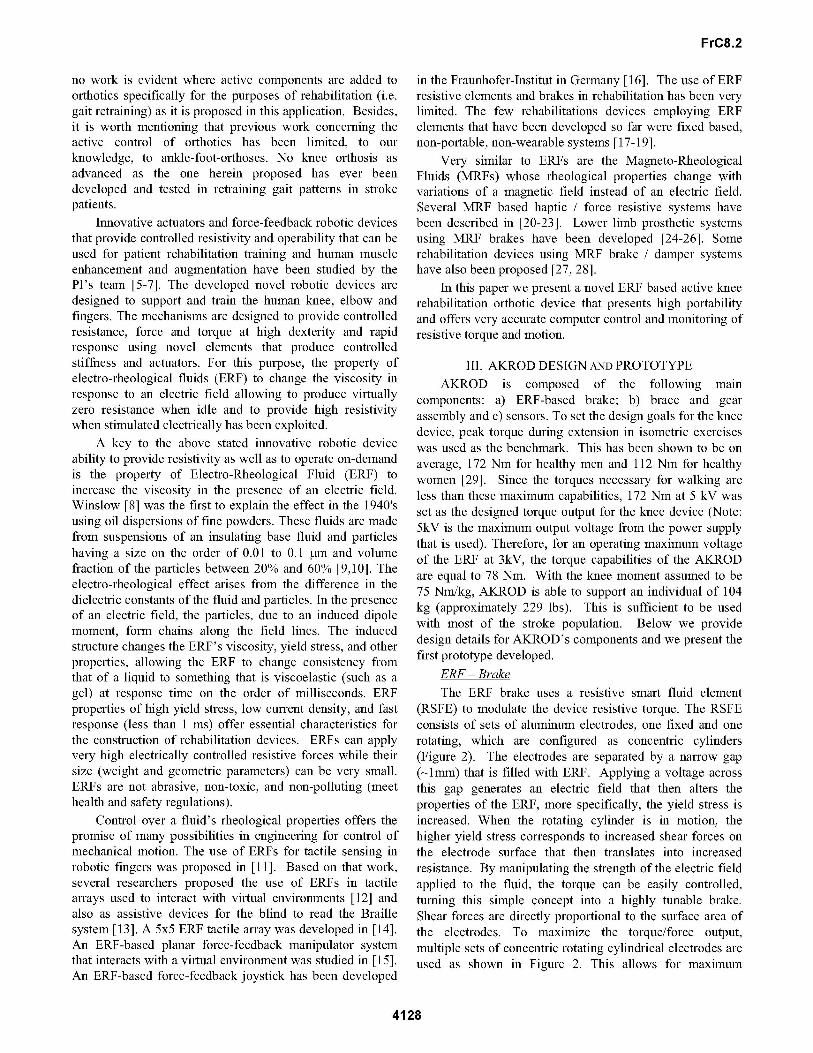
In this paper, we present the design, control and testingof a novel, smart and portable Active Knee RehabilitationOrthotic Device (AKROD), shown in Figure 1. The maintorque generation component of the device is a resistivevariable damper that is the key to foster training of moreefficient and clinically desirable knee biomechanicalpatterns in stroke patients. This component will be reliedupon in order to avoid knee hyperextension and foster re-learning of a knee flexion pattern during stance. Also, itwill be relied upon to correct stiff-legged pattern, defined aslimited knee flexion during swing.
AkROI)
Figure 1: Active Knee Rehabilitation Orthotic Device.
The AKROD is composed of straps and rigidcomponents for attachment to the leg, with a central hingemechanism where a gear system is connected. The keyfeatures of the proposed AKROD include: a compact,lightweight design with highly tunable resistive torquecapabilities, and sensors (encoder and torque), and real-timecapabilities for closed loop computer control for optimizinggait retraining. The controllable variable resistance isachieved through an electro-rheological fluid (ERF) elementthat connects to the output of the gear system. Using theelectrically controlled rheological properties of ERFs,compact brakes capable of supplying high resistive andcontrollable torques, have been developed. Concentriccylinders, acting as electrodes supply the necessary electricfield to activate the fluid. Simultaneously, these plates,when charged and rotating, act as surfaces upon which theactivated fluid creates a shear force in response to rotation.This paper presents the detailed design, closed loop controland initial human testing ofAKROD.
II. BACKGROUNDAn orthotic by strict definition is a specialized
mechanical device that supports or supplements weakenedor abnormal joints or limbs [2]. The Sports MedicineCommittee of the American Academy of OrthopedicSurgeons has classified knee braces into four categories:prophylactic, rehabilitative, functional and patellofemoral.The majority of these devices can be considered passivedevices. They provide stability, apply precise pressure, orhelp maintain alignment of the joints. Improved technologyhas allowed for advancements where these devices can bedesigned to apply a form of tension to resist motion of thejoint. These devices induce quicker recovery and are moreeffective at restoring proper biomechanics and improvingmuscle function. These may employ torsion springs, pistonsand simple mechanical devices to make them "semi-active",rather than passive orthotics.
Some of the more innovative designs allow the torsionto be adjusted; giving some variety and even furtherimprovements in efficiency over a simple passive device.However, their shortcoming is in their inability to beadjusted in real-time, which is the most ideal form of adevice for rehabilitation. This introduces a second class ofdevices beyond passive orthotics. It is comprised of"active" or powered devices, and although morecomplicated in designs, they are definitely the most versatile.An active or powered orthotic, usually employs some typeof actuator(s). These types of devices are ideal forproviding additional support to the knee, due to their uniqueability to adjust in real-time. The actuator aspects of thesedevices allow them to perform augmentations andenhancements on the human muscles. Examples of workrecently performed in this line of research are the onesdescribed in [3,4]. Both groups have explored the use ofadvanced robotics and innovative actuators to improve thefunctional use of ankle-foot-orthoses. Unfortunately,advances in active orthotics have generally been limitedonly to assistance and enhancement. Very little and close to
4127
FrC8.2
no work is evident where active components are added toorthotics specifically for the purposes of rehabilitation (i.e.gait retraining) as it is proposed in this application. Besides,it is worth mentioning that previous work concerning theactive control of orthotics has been limited, to ourknowledge, to ankle-foot-orthoses. No knee orthosis asadvanced as the one herein proposed has ever beendeveloped and tested in retraining gait patterns in strokepatients.
Innovative actuators and force-feedback robotic devicesthat provide controlled resistivity and operability that can beused for patient rehabilitation training and human muscleenhancement and augmentation have been studied by thePI's team [5-7]. The developed novel robotic devices aredesigned to support and train the human knee, elbow andfingers. The mechanisms are designed to provide controlledresistance, force and torque at high dexterity and rapidresponse using novel elements that produce controlledstiffness and actuators. For this purpose, the property ofelectro-rheological fluids (ERF) to change the viscosity inresponse to an electric field allowing to produce virtuallyzero resistance when idle and to provide high resistivitywhen stimulated electrically has been exploited.
A key to the above stated innovative robotic deviceability to provide resistivity as well as to operate on-demandis the property of Electro-Rheological Fluid (ERF) toincrease the viscosity in the presence of an electric field.Winslow [8] was the first to explain the effect in the 1940'susing oil dispersions of fine powders. These fluids are madefrom suspensions of an insulating base fluid and particleshaving a size on the order of 0.01 to 0.1 ptm and volumefraction of the particles between 20% and 60% [9,10]. Theelectro-rheological effect arises from the difference in thedielectric constants of the fluid and particles. In the presenceof an electric field, the particles, due to an induced dipolemoment, form chains along the field lines. The inducedstructure changes the ERF's viscosity, yield stress, and otherproperties, allowing the ERF to change consistency fromthat of a liquid to something that is viscoelastic (such as agel) at response time on the order of milliseconds. ERFproperties of high yield stress, low current density, and fastresponse (less than 1 ms) offer essential characteristics forthe construction of rehabilitation devices. ERFs can applyvery high electrically controlled resistive forces while theirsize (weight and geometric parameters) can be very small.ERFs are not abrasive, non-toxic, and non-polluting (meethealth and safety regulations).
Control over a fluid's rheological properties offers thepromise of many possibilities in engineering for control ofmechanical motion. The use of ERFs for tactile sensing inrobotic fingers was proposed in [11]. Based on that work,several researchers proposed the use of ERFs in tactilearrays used to interact with virtual environments [12] andalso as assistive devices for the blind to read the Braillesystem [13]. A 5x5 ERF tactile array was developed in [14].An ERF-based planar force-feedback manipulator systemthat interacts with a virtual environment was studied in [15].An ERF-based force-feedback joystick has been developed
in the Fraunhofer-Institut in Germany [16]. The use of ERFresistive elements and brakes in rehabilitation has been verylimited. The few rehabilitations devices employing ERFelements that have been developed so far were fixed based,non-portable, non-wearable systems [17-19].
Very similar to ERFs are the Magneto-RheologicalFluids (MRFs) whose rheological properties change withvariations of a magnetic field instead of an electric field.Several MRF based haptic / force resistive systems havebeen described in [20-23]. Lower limb prosthetic systemsusing MRF brakes have been developed [24-26]. Somerehabilitation devices using MRF brake / damper systemshave also been proposed [27, 28].
In this paper we present a novel ERF based active kneerehabilitation orthotic device that presents high portabilityand offers very accurate computer control and monitoring ofresistive torque and motion.
III. AKROD DESIGN AND PROTOTYPEAKROD is composed of the following main
components: a) ERF-based brake; b) brace and gearassembly and c) sensors. To set the design goals for the kneedevice, peak torque during extension in isometric exerciseswas used as the benchmark. This has been shown to be onaverage, 172 Nm for healthy men and 112 Nm for healthywomen [29]. Since the torques necessary for walking areless than these maximum capabilities, 172 Nm at 5 kV wasset as the designed torque output for the knee device (Note:5kV is the maximum output voltage from the power supplythat is used). Therefore, for an operating maximum voltageof the ERF at 3kV, the torque capabilities of the AKRODare equal to 78 Nm. With the knee moment assumed to be75 Nm/kg, AKROD is able to support an individual of 104kg (approximately 229 lbs). This is sufficient to be usedwith most of the stroke population. Below we providedesign details for AKROD's components and we present thefirst prototype developed.
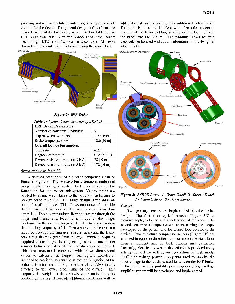
ERF- BrakeThe ERF brake uses a resistive smart fluid element
(RSFE) to modulate the device resistive torque. The RSFEconsists of sets of aluminum electrodes, one fixed and onerotating, which are configured as concentric cylinders(Figure 2). The electrodes are separated by a narrow gap( 1mm) that is filled with ERF. Applying a voltage acrossthis gap generates an electric field that then alters theproperties of the ERF, more specifically, the yield stress isincreased. When the rotating cylinder is in motion, thehigher yield stress corresponds to increased shear forces onthe electrode surface that then translates into increasedresistance. By manipulating the strength of the electric fieldapplied to the fluid, the torque can be easily controlled,turning this simple concept into a highly tunable brake.Shear forces are directly proportional to the surface area ofthe electrodes. To maximize the torque/force output,multiple sets of concentric rotating cylindrical electrodes areused as shown in Figure 2. This allows for maximum
4128
FrC8.2
shearing surface area while maintaining a compact overallvolume for the device. The general design and performancecharacteristics of the knee orthosis are listed in Table 1. TheERF brake was filled with the 3365S fluid, from SmartTechnology LTD (http://www.smarttec.co.uk/). All teststhroughout this work were performed using the same fluid.
SER BkeS_ __W Seat
added through suspension from an additional pelvic brace.The orthosis does not interfere with electrode placementbecause of the foam padding used as an interface betweenthe brace and the patient. The padding allows for thinelectrodes to be used without any alterations to the design orattachments.AKRODB ()Owm*wedSt_P_
k
I
/Figure 2: ERF Brake.
Table 1: System Characteristics ofAKROD
Number of concentric cylinders 5Gap between cylinders 1.27 [mm]Brake torque (at 3 kV) 12.6 [N m]Overall Device ParametersGear ratio 6.2:1Degrees of rotation ContinuousDevice resistive torque (at 3 kV) 78 [N m]Device resistive torque (at 5 kV) 172 [N m]
/t
Brace and Gear Assemblv
A detailed description of the brace components can befound in Figure 3. The resistive brake torque is multipliedusing a planetary gear system that also serves as thefoundation for the sensor sub-system. Velcro straps are
padded by foam, which forms to the patient's leg helping toprevent brace migration. The hinge design is the same on
both sides of the brace. This allows one to switch the sidethat the knee orthosis is on; so the knee brace can be used on
either leg. Force is transmitted from the wearer through thestraps and frame and leads to a torque at the hinge.Contained in the exterior hinge is the planetary gear systemthat multiply torque by 6.2:1. Two compression sensors are
mounted between the ring gear (largest gear) and the framepreventing the ring gear from moving. When a torque issupplied to the hinge, the ring gear pushes on one of thesensors (which one depends on the direction of motion).This force measure is combined with known dimensionalvalues to calculate the torque. An optical encoder isincluded to precisely measure joint motion. Migration of theorthosis is minimized through the use of an AFO that isattached to the lower brace arms of the device. Thissupports the weight of the orthosis while maintaining itsposition on the leg. If needed, additional constraints will be
Figure 3: AKROD Brace: A- Brace Detail; B - Sensor Detail;C - Hinge Exterior; D - Hinge Interior.
Sensors
Two primary sensors are implemented into the devicedesign. The first is an optical encoder (Figure 3D) tomeasure angle, velocity, and acceleration of the knee. Thesecond sensor is a torque sensor for measuring the torquedeveloped by the patient and for closed-loop control of thedevice. Two miniature compressor sensors (Figure 3B) are
arranged in opposite directions to measure torque via a forcefrom a moment arm in both flexion and extension.Currently, electrical power to the orthosis is provided usinga tether for off-the-wall power acquisition. A Trek model610C high voltage power supply was used to amplify theinput voltage to the levels needed to activate the ER-F brake.In the future, a fully portable power supply / high voltageamplifier system will be developed and implemented.
4129
ERF Brake Parameters:-./ - --.1
FrC8.2
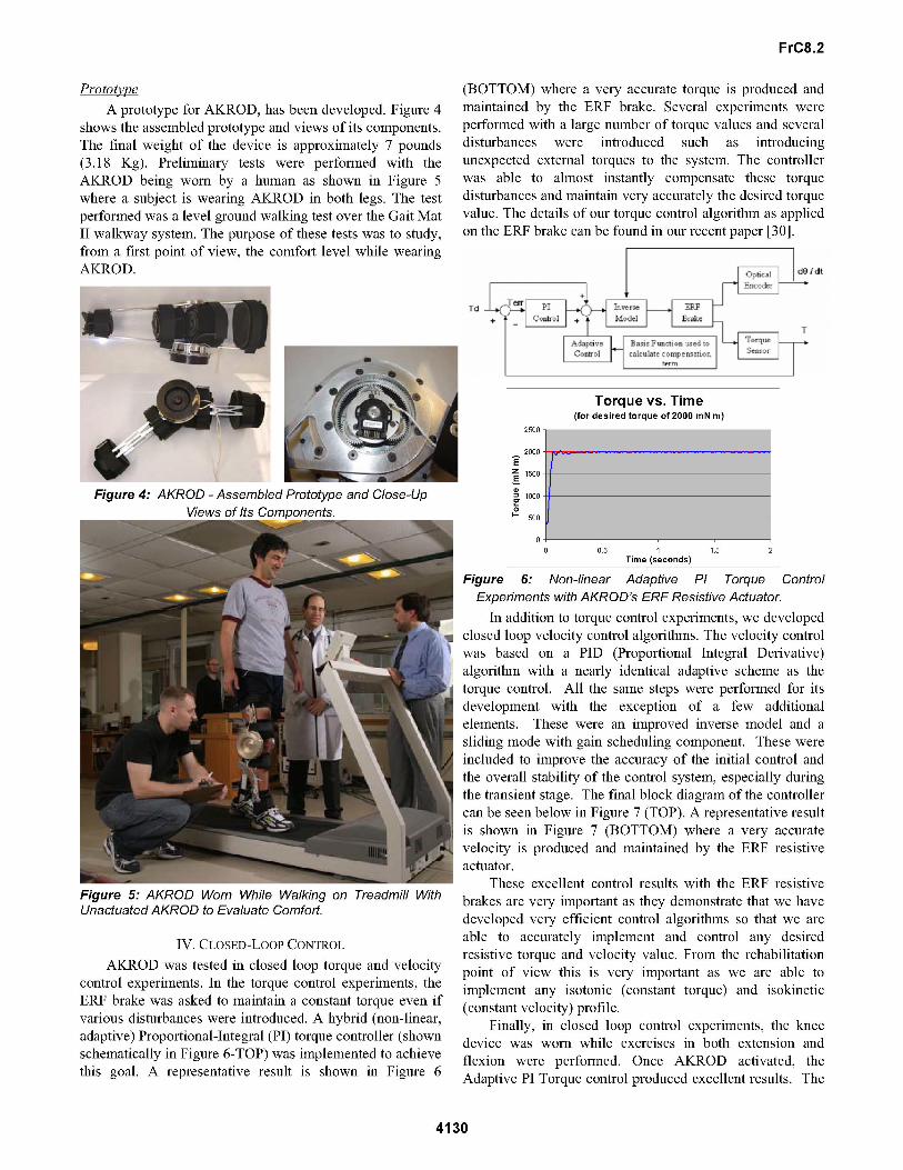
PrototipeA prototype for AKROD, has been developed. Figure 4
shows the assembled prototype and views of its components.The final weight of the device is approximately 7 pounds(3.18 Kg). Preliminary tests were performed with theAKROD being worn by a human as shown in Figure 5where a subject is wearing AKROD in both legs. The testperformed was a level ground walking test over the Gait MatII walkway system. The purpose of these tests was to study,from a first point of view, the comfort level while wearingAKROD.
Figure 4: AKROD - Assembled Prototype and Close-UpViews of Its Comnonents.
Figure 5: AKROD Worn While Walking on Treadmill WithUnactuated AKROD to Evaluate Comfort.
IV. CLOSED-LOOP CONTROLAKROD was tested in closed loop torque and velocity
control experiments. In the torque control experiments, theERF brake was asked to maintain a constant torque even ifvarious disturbances were introduced. A hybrid (non-linear,adaptive) Proportional-Integral (PI) torque controller (shownschematically in Figure 6-TOP) was implemented to achievethis goal. A representative result is shown in Figure 6
(BOTTOM) where a very accurate torque is produced andmaintained by the ER-F brake. Several experiments were
performed with a large number of torque values and severaldisturbances were introduced such as introducingunexpected external torques to the system. The controllerwas able to almost instantly compensate these torquedisturbances and maintain very accurately the desired torquevalue. The details of our torque control algorithm as appliedon the ERF brake can be found in our recent paper [30].
000 dO Idtn-
Figure 6: Non-linear Adaptive PI Torque ControlExperiments with AKROD's ERF Resistive Actuator.
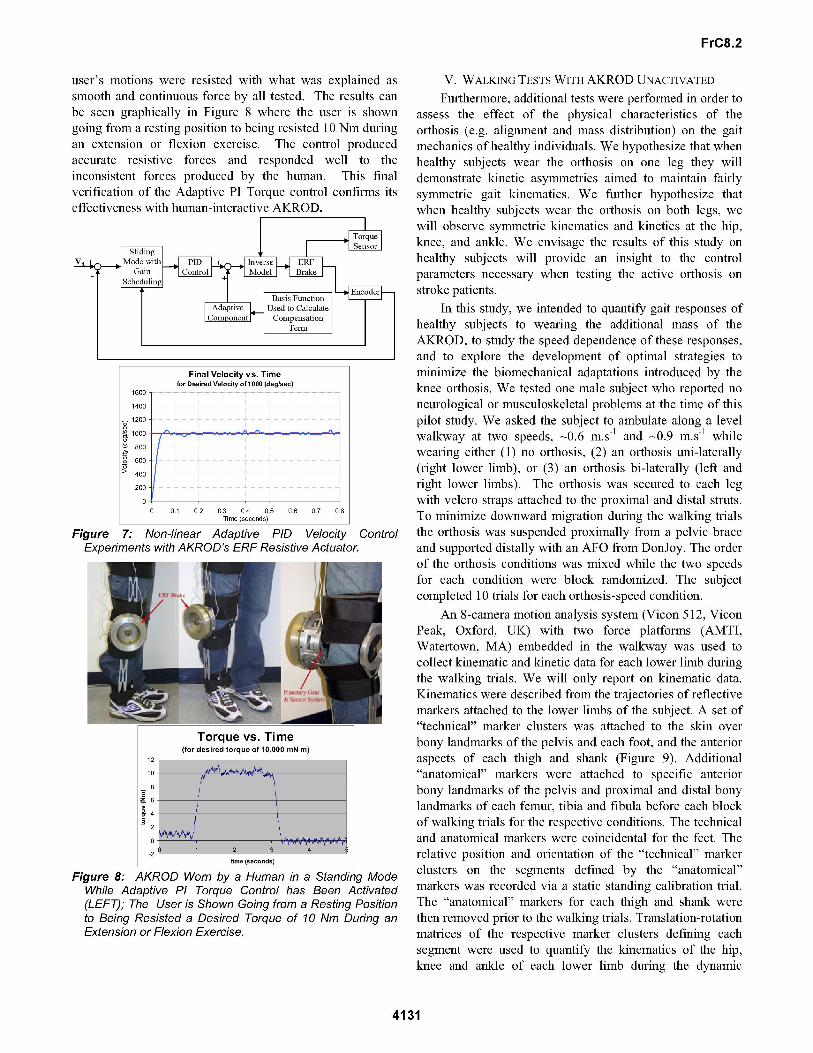
In addition to torque control experiments, we developedclosed loop velocity control algorithms. The velocity controlwas based on a PID (Proportional Integral Derivative)algorithm with a nearly identical adaptive scheme as thetorque control. All the same steps were performed for itsdevelopment with the exception of a few additionalelements. These were an improved inverse model and a
sliding mode with gain scheduling component. These were
included to improve the accuracy of the initial control andthe overall stability of the control system, especially duringthe transient stage. The final block diagram of the controllercan be seen below in Figure 7 (TOP). A representative resultis shown in Figure 7 (BOTTOM) where a very accuratevelocity is produced and maintained by the ERF resistiveactuator.
These excellent control results with the ERF resistivebrakes are very important as they demonstrate that we havedeveloped very efficient control algorithms so that we are
able to accurately implement and control any desiredresistive torque and velocity value. From the rehabilitationpoint of view this is very important as we are able toimplement any isotonic (constant torque) and isokinetic(constant velocity) profile.
Finally, in closed loop control experiments, the kneedevice was worn while exercises in both extension andflexion were performed. Once AKROD activated, theAdaptive PI Torque control produced excellent results. The
4130
Torque vs. Time(for desired torque of 2000 mN m)
2500
2000EZ 1500E
1000
0500
O
0 0.5 1 1.5 2Time (seconds)
Td
FrC8.2
user's motions were resisted with what was explained assmooth and continuous force by all tested. The results canbe seen graphically in Figure 8 where the user is showngoing from a resting position to being resisted 10 Nm duringan extension or flexion exercise. The control producedaccurate resistive forces and responded well to theinconsistent forces produced by the human. This finalverification of the Adaptive PI Torque control confirms itseffectiveness with human-interactive AKROD.
Final Velocity vs. Timefor Desired Velocity of 1000 (deg/sec)
1600
1400
1200
800
a) 600-
>400-200
00 0.1 0.2 0.3 0.4 0.5 0.6 0.7 0.8
Time (seconds)
Figure 7: Non-linear Adaptive PID Velocity ControlExperiments with AKROD's ERF Resistive Actuator.
Torque vs. Time(for desired torque of 10,000 mN m)
12
10
Z6
a=42
-21 3
time (seconds)
Figure 8: AKROD Worn by a Human in a Standing ModeWhile Adaptive PI Torque Control has Been Activated(LEFT); The User is Shown Going from a Resting Positionto Being Resisted a Desired Torque of 10 Nm During anExtension or Flexion Exercise.
V. WALKING TESTS WITH AKROD UNACTIVATEDFurthermore, additional tests were performed in order to
assess the effect of the physical characteristics of theorthosis (e.g. alignment and mass distribution) on the gaitmechanics of healthy individuals. We hypothesize that whenhealthy subjects wear the orthosis on one leg they willdemonstrate kinetic asymmetries aimed to maintain fairlysymmetric gait kinematics. We further hypothesize thatwhen healthy subjects wear the orthosis on both legs, wewill observe symmetric kinematics and kinetics at the hip,knee, and ankle. We envisage the results of this study onhealthy subjects will provide an insight to the controlparameters necessary when testing the active orthosis onstroke patients.
In this study, we intended to quantify gait responses ofhealthy subjects to wearing the additional mass of theAKROD, to study the speed dependence of these responses,and to explore the development of optimal strategies tominimize the biomechanical adaptations introduced by theknee orthosis. We tested one male subject who reported noneurological or musculoskeletal problems at the time of thispilot study. We asked the subject to ambulate along a levelwalkway at two speeds, 0.6 m.s-1 and 0.9 m.s-1 whilewearing either (1) no orthosis, (2) an orthosis uni-laterally(right lower limb), or (3) an orthosis bi-laterally (left andright lower limbs). The orthosis was secured to each legwith velcro straps attached to the proximal and distal struts.To minimize downward migration during the walking trialsthe orthosis was suspended proximally from a pelvic braceand supported distally with an AFO from DonJoy. The orderof the orthosis conditions was mixed while the two speedsfor each condition were block randomized. The subjectcompleted 10 trials for each orthosis-speed condition.
An 8-camera motion analysis system (Vicon 512, ViconPeak, Oxford, UK) with two force platforms (AMTI,Watertown, MA) embedded in the walkway was used tocollect kinematic and kinetic data for each lower limb duringthe walking trials. We will only report on kinematic data.Kinematics were described from the trajectories of reflectivemarkers attached to the lower limbs of the subject. A set of"technical" marker clusters was attached to the skin overbony landmarks of the pelvis and each foot, and the anterioraspects of each thigh and shank (Figure 9). Additional"anatomical" markers were attached to specific anteriorbony landmarks of the pelvis and proximal and distal bonylandmarks of each femur, tibia and fibula before each blockof walking trials for the respective conditions. The technicaland anatomical markers were coincidental for the feet. Therelative position and orientation of the "technical" markerclusters on the segments defined by the "anatomical"markers was recorded via a static standing calibration trial.The "anatomical" markers for each thigh and shank werethen removed prior to the walking trials. Translation-rotationmatrices of the respective marker clusters defining eachsegment were used to quantify the kinematics of the hip,knee and ankle of each lower limb during the dynamic
4131
FrC8.2
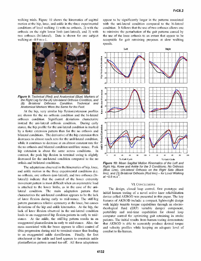
walking trials. Figure 10 shows the kinematics of sagittalmotion at the hip, knee, and ankle in the three experimentalconditions of level walking 1) with no orthosis, 2) with theorthosis on the right lower limb (uni-lateral), and 3) withtwo orthoses (bi-lateral). Data is shown for one subjectwalking at 0.9 m.s-1.
appear to be significantly larger in the patterns associatedwith the uni-lateral condition compared to the bi-lateralcondition. It follows that the use of two orthoses allows one
to minimize the perturbation of the gait patterns caused bythe use of the knee orthosis to an extent that appear to beacceptable for gait retraining purposes at slow walkingspeeds.
Left
.=
=-
40
Right
Figure 9: Technical (Red) and Anatomical (Blue) Markers ofthe Right Leg for the (A) Uni-lateral Orthosis Condition, and(B) Bi-lateral Orthoses Condition. Technical andAnatomical Markers Were the Same for the Feet.At the hip, very similar hip flexion/extension profiles
are shown for the no orthosis condition and the bi-lateralorthoses condition. Significant deviations characterizeinstead the uni-lateral orthosis condition. During earlystance, the hip profile for the uni-lateral condition is markedby a faster extension pattern than for the no orthosis andbilateral conditions. The derivative of the hip extension thendecreases to almost reach zero for the unil-lateral condition,while it continues to decrease at an almost constant rate forthe no orthosis and bilateral condition until late stance. Peakhip extension is about the same across conditions. Incontrast, the peak hip flexion in terminal swing is slightlydecreased for the uni-lateral condition compared to the no
orthsis and bi-lateral conditions.The adaptations observed in the kinematics of hip, knee,
and ankle motion in the three experimental conditions (i.e.no orthosis, one orthosis (uni-lateral), and two orthoses (bi-lateral)) indicate that the control of the lower extremitymovement pattern is most difficult when an asymmetric loadis attached to the lower limbs, as in the case of the uni-lateral condition. The main adaptation pattern thatcharacterizes the uni-lateral condition appears to be the lackof knee flexion during early to mid-stance. The stiff-legpattern guarantees relative symmetry at the knee, but causes
deviations of the hip and ankle kinematics. At the hip, thelack of knee flexion observed in the uni-lateral conditionleads to an exaggerated hip flexion pattern in early to mid-stance. At the ankle, the stiff-leg pattern results in an
exaggerated plantarflexion in early to mid-stance. Also, themass associated with the brace appears to affect control oftibia progression during mid to terminal-stance thus leadingto an exaggerated ankle dorsiflexion. Finally, the footattachment at the ankle and heel appears to constrain ankleplantarflexion pattern around toe-off. All these adaptations
0
._
PZ
40
60
20
10
0
-10
-20'0 20 40 60 80 100
% Gait Cycle
0 20 40 60 80 100
% Gait Cycle
Figure 10: Mean Sagittal Motion Kinematics of the Left andRight Hip, Knee and Ankle for the 3 Conditions: No Orthosis(Blue Line), Uni-lateral Orthosis on the Right Side (Blackline), and (3) Bi-lateral Orthosis (Red line) - for Level Walkingat-0.9m.s
VI. CONCLUSIONSThe design, closed loop control, first prototype and
initial human testing of a novel active knee rehabilitationdevice called AKROD was presented in this paper. The keyfeatures of AKROD include: a compact, lightweight designwith highly tunable torque capabilities through an electro-rheological fluid (ERF) variable damper component,portability and real-time capabilities for closed loopcomputer control for optimizing gait retraining in strokepatients. The initial results from human testing demonstratethat AKROD is able to accurately produce desired torqueand velocity profiles while keeping an adequate level ofcomfort to the human.
4132
40 .4
20;f....................
............. ...... ....... A............ ..... ............ .....
R",
............ ...........
..................
..........................
........... ............ ............ ............ ............ ........... ............ ............ ..........-
oni
............ ............ ............
........ ... ....
............ ............
............
.............
............ ..........
.........................
FrC8.2
REFERENCES1. National Institute of Child Health & Human Development,
"Research Plan for the National Center for MedicalRehabilitation Research," National Institutes of HealthPublication No. 93-3 509, March 1993.
2. M. Cook and S. M. Hussey, Assistive Technologies:Principles and Practice, 2nd ed: Mosby, 2002.
3. Blaya JA, Herr H, "Adaptive Control of a Variable-ImpedanceAnkle-Foot Orthosis to Assist Drop-Foot Gait", IEEE TransNeural Syst Rehabil Eng, 12(1): 24-31, 2004.
4. Gordon KE, Sawicki GS, Ferris DP, "MechanicalPerformance of Artificial Pneumatic Muscles to Power anAnkle-Foot-Orthosis", JBiomech (in press).
5. Weinberg B., Nikitczuk J., Fisch A., Mavroidis C."Development of Electro-Rheological Fluidic ResistiveActuators for Haptic Vehicular Instrument Controls",Smart Materials and Structures, Vol. 14, pp. 1107-1119,2005.
6. Vitrani M., Nikitczuk J., Morel G. and Mavroidis C.,"Torque Control of Electro-Rheological FluidicResistive Actuators for Haptic Vehicular InstrumentsControl," Journal of Dynamic Systems, Measurementand Control, Transactions of the ASME, Vol. 128, No.2, pp. 2 16-226, 2006.
7. Khanicheh A., Muto A., Triantafyllou C., Weinberg B.,Astrakas L., Tzika A., and Mavroidis C., "MR CompatibleERF Driven Hand Rehabilitation Device", Proceedings of the9th IEEE International Conference on Rehabilitation Robotics(ICORR 2005), June 28 - July 1, 2005, Chicago, IL.
8. Winslow W. M., "Induced Fibrillation of Suspensions,"Journal ofApplied Physics, Vol. 20, 1949, pp. 1137.
9. Conrad H., "Properties and Design of ElectrorheologicalSuspensions," MRS Bulletin, Vol. 23, No. 8, August 1998, pp.35-42.
10. Weiss K. D., Carlson D. J. and Coulter J. P., "MaterialAspects of Electrorheological Systems," in Advances inIntelligent Material Systems and Structures- Volume 2:Advances Electrorheological Fluids, Kohudic M. A. (Editor).
11. Kenaley G. L. and Cutkosky M. R., "Electrorheological Fluid-Based Robotic Fingers With Tactile Sensing," Proceedings ofthe 1989 IEEE International Conference on Robotics andAutomation, Scottsdale AR, pp. 132-136.
12. Wood D., "Editorial: Tactile Displays: Present and Future,"Displays-Technology and Applications, Vol. 18, No. 3, 1998,pp. 125-128.
13. Monkman G. J., "Electrorheological Tactile Display",Presence, MIT Press, Vol. 1, No. 2, 1992.
14. Taylor P. M., Hosseini-Sianaki A. and Varley C. J., "SurfaceFeedback for Virtual Environment Systems UsingElectrorheological Fluids," International Journal of ModernPhysics B, Vol. 10, No. 23 & 24, 1996, pp. 3011-3018.
15. Sakaguchi M. and Furusho J., " Force Display System UsingParticle-Type Electrorheological Fluids," Proceedings of the1998 IEEE International Conference on Robotics andAutomation, Leuven, Belgium, May 1998, pp. 2586-2590.
16. Bose H., Berkemeier J. and Trendler A., "Haptic SystemBased on Electrorheological Fluid," Proceedings of theACTUATOR 2000 Conference, 19-21 June 2000, BremenGERMANY.
17. Sakaguchi M., Furusho J., Genda E., "Basic Study onRehabilitation Training System Using ER Actuators," Proc. ofthe IEEE International Conference on Systems, Man andCybernetics, Vol. 1, 1999, pp. 1-135 - 1-140.
18. Koyanagi K., Furusho J., Ryu U. Inoue A., "Development ofRehabilitation System for the Upper Limbs in a NEDOProject," Proceedings - IEEE International Conference onRobotics andAutomation, Vol. 3, 2003, pp. 4016-4022.
19. Kikuchi T., Furusho J., Oda K., "Development of IsokineticExercise Machine Using ER Brake," Proceedings - IEEEInternational Conference on Robotics andAutomation, Vol. 1,2003, pp. 214-219.
20. Li W.H., Du H., Guo N.Q., Kosasih P.B.,"Magnetorheological Fluids Based Haptic Device," SensorReview, Vol. 24, No. 1, 2004, pp. 68-73.
21. Liu Y., Davidson R.I., Taylor, P.M., Ngu, J.D., ZarragaJ.M.C., "Single Cell Magnetorheological Fluid Based TactileDisplay," Displays, Vol. 26, No. 1, January, 2005, pp. 29-35.
22. Rov A. M., Neelakantan V. A., Washington G., "Design andDevelopment of Passive and Active Force Feedback SystemsUsing Magnetorheological Fluids, American Society ofMechanical Engineers, Aerospace Division (Publication) AD,Vol. 68, 2003, pp. 333-339.
23. Scilingo E. P., Sgambelluri N., De Rossi D., Bicchi, A.,"Towards a Haptic Black Box for Free-Hand Softness andShape Exploration," Proc. - IEEE International Conferenceon Robotics andAutomation, Vol. 2, 2003, pp. 2412-2417.
24. Carlson J.D., Matthis W., Toscano J.R., "Smart ProstheticsBased on Magnetorheological Fluids," Proceedings of SPIE -The International Societyfor Optical Engineering, Vol. 4332,2001, pp. 308-316.
25. Furusho J., Takesue N., Nakagaki S., Tsuda T., Nakagawa A.,Morimoto S., "Development of Intelligent Prosthetic AnkleJoint (1st report, development of linear-type MR-fluidbrake)," Nippon Kikai Gakkai Ronbunshu, CHen/Transactions of the Japan Society of MechanicalEngineers, Part C, Vol. 70, No. 7, July, 2004, pp. 2163-2170.
26. Herr H., Wilkenfeld A., "User-Adaptive Control of aMagnetorheological Prosthetic Knee," Industrial Robot, Vol.30, No. 1, 2003, pp. 42-55.
27. Dong S., Lu K., Sun J.Q., Rudolph K., "Rehabilitation Devicewith Variable Resistance and Intelligent Control, MedicalEngineering and Physics, Vol. 27, No. 3, April, 2005, pp.249-255.
28. Li W.H, Du H., "Development of an Ankle PhysiotherapyDevice Using an MR Damper," International Journal ofAdvanced Manufacturing Technology, Vol. 25, No. 3-4,February, 2005, pp. 205-213.
29. Neder, JA; Nery, LE; Shinzato, GT; Andrade, MS; Peres, C;Silva, AC, "Reference Values for Concentric Knee IsokineticStrength and Power in Nonathletic Men and Women from 20to 80 Years Old", Journal of Orthopaedic & Sports PhysicalTherapy, 29(2), 1999, pp. 116 - 126.
30. Nikitczuk J., Das A., Vyas H., Weinberg B., Mavroidis C.,"Adaptive Torque Control of Electro-Rheological FluidBrakes Used in Active Knee Rehabilitation Devices",Proceedings of the 2006 IEEE International Conference onRobotics andAutomation, Orlando, FL, May 15 - 19, 2006.
4133