
Design, Construction and Performance Evaluation of a ...
12
Advances in Engineering Design Technology Vol. 3, 2021 pp. 86-97 ISSN-2682-5848 86 Design, Construction and Performance Evaluation of a Horizontal Sand Screening and Heating Machine Eyere Emagbetere, ThankGod Enatimi Boye, Jospeh Oyetola Oyekale, Benjamin Ufuoma Oreko Department of Mechanical Engineering, Federal University of Petroleum Resources, Effurun, Nigeria. *Corresponding author: [email protected] ARTICLE INFORMATION ABSTRACT Article history: Received 28 Oct. 2021 Revised 22 November 2021 Accepted 25 November 2021 Available online 16 December 2021 Quality sand of specific grain sizes and without contagious micro- organism is particularly needed for water bio-filters and other applications. Existing sand screening machines are large, expensive, and do not have capability to improve the quality of sand. The purpose of this work is to develop and evaluate the performance of a portable sand sieving and heating machine. The parts of the machine were designed based on standard equations in the literature. The machine was constructed and tested to evaluate its performance, and then modelled with SOLIDWORKS to determine the temperature distribution and Von-Mises stresses. The machine performed satisfactorily when tested showing a strong correlation between the sieving time and its effectiveness. The maximum Von- Mises stress (16 MN/m 2 ) is far lower than the yield strength of the used material (250 mN/m 2 ), indicating that it is unlikely to fail during operation. The maximum simulated temperature in the outer part of the heating chamber was found to be approximately 52 o C which is low enough for human safety. Conclusively, the developed portable sand sieving machine has a good strength, operates at a safe temperature, and effective for producing high grade sand void of contagious micro-organism as needed particularly for water filters and other applications. Keywords: Sand screen, sand filters, meshes, sand treatment, water filter. https://doi.org/10.37933/nipes.a/3.2.2021.8 https://nipesjournals.org.ng © 2021 NIPES Pub. All rights reserved 1. Introduction There are numerous applications of sand: bricks making, fencing, water purification, paint making, abrasion and glass making. In its original form, sand comes in varying size and certain level of impurities thereby making them not suitable to be used directly from source. Sand screening is, thus, an important process in industries that utilize sand, and is achieved using various sieving techniques [1]. There is a general procedure adopted for sieve designs. According to Gupta and Yan [2], the surface, screen type and screen movement are the three main considerations for sieve designs, and the perforated sieve surfaces are commonly used for sand sieving compared to woven and grizzle types. These perforated sieves are square, circular or rectangular type, and the motion could be either an agitated, rotating or reciprocating motion. Additionally, the size of mesh needs be determined following some basic standards, namely, Tyler, USA, British, German, IP and the ISO standard sieve series which are listed in the literature [3, 4, 5]. Furthermore, several factors can affect the
-
Upload
khangminh22 -
Category
Documents
-
view
0 -
download
0
Transcript of Design, Construction and Performance Evaluation of a ...

Advances in Engineering Design Technology Vol. 3, 2021 pp. 86-97 ISSN-2682-5848
86
Design, Construction and Performance Evaluation of a Horizontal Sand
Screening and Heating Machine
Eyere Emagbetere, ThankGod Enatimi Boye, Jospeh Oyetola Oyekale, Benjamin Ufuoma
Oreko Department of Mechanical Engineering, Federal University of Petroleum Resources, Effurun, Nigeria.
*Corresponding author: [email protected]
ARTICLE INFORMATION ABSTRACT
Article history:
Received 28 Oct. 2021
Revised 22 November 2021
Accepted 25 November 2021
Available online 16 December 2021
Quality sand of specific grain sizes and without contagious micro-
organism is particularly needed for water bio-filters and other
applications. Existing sand screening machines are large, expensive,
and do not have capability to improve the quality of sand. The
purpose of this work is to develop and evaluate the performance of
a portable sand sieving and heating machine. The parts of the
machine were designed based on standard equations in the
literature. The machine was constructed and tested to evaluate its
performance, and then modelled with SOLIDWORKS to determine
the temperature distribution and Von-Mises stresses. The machine
performed satisfactorily when tested showing a strong correlation
between the sieving time and its effectiveness. The maximum Von-
Mises stress (16 MN/m2) is far lower than the yield strength of the
used material (250 mN/m2), indicating that it is unlikely to fail during
operation. The maximum simulated temperature in the outer part of
the heating chamber was found to be approximately 52oC which is
low enough for human safety. Conclusively, the developed portable
sand sieving machine has a good strength, operates at a safe
temperature, and effective for producing high grade sand void of
contagious micro-organism as needed particularly for water filters
and other applications.
Keywords:
Sand screen, sand filters, meshes, sand treatment, water filter.
https://doi.org/10.37933/nipes.a/3.2.2021.8
https://nipesjournals.org.ng
© 2021 NIPES Pub. All rights reserved
1. Introduction
There are numerous applications of sand: bricks making, fencing, water purification, paint making,
abrasion and glass making. In its original form, sand comes in varying size and certain level of
impurities thereby making them not suitable to be used directly from source. Sand screening is, thus,
an important process in industries that utilize sand, and is achieved using various sieving techniques
[1]. There is a general procedure adopted for sieve designs. According to Gupta and Yan [2], the
surface, screen type and screen movement are the three main considerations for sieve designs, and
the perforated sieve surfaces are commonly used for sand sieving compared to woven and grizzle
types. These perforated sieves are square, circular or rectangular type, and the motion could be either
an agitated, rotating or reciprocating motion. Additionally, the size of mesh needs be determined
following some basic standards, namely, Tyler, USA, British, German, IP and the ISO standard
sieve series which are listed in the literature [3, 4, 5]. Furthermore, several factors can affect the

Eyere Emagbetere et al. / Advances in Engineering Design Technology
3, 2021 pp. 86-97
87
sieving efficiency. Whereas some factors are vital at the design stage, others may be considered
during the sieve operation. Duration of sieving, for example, can affect the efficiency during
operation because the more time spent on the screen machine, the more efficiently it would have
separated the constituent [6, 7]. One factor that can be considered at design stage is the method of
sieve, as the stack method, for instance, in which several screen sizes are mounted to separate sand
into different sizes, has been found to be the best technique [8]. Additionally, the particle collision
and vibration parameters which can also be altered at the design stage have been found to affect
sieving efficiency [9]. Finally, screen blocking that can negatively affect sieve efficiency, can better
be tackled using vibratory machines compared to rotary and drum types [10].
Notwithstanding, there are a number of sieving machines developed for various applications in
recent time. Nwigbo et al. [11], developed a manually operated stacked sieve that can work without
any power source. Moreso, there are some multi-staged sieving machines that were developed
recently. There are the two-staged sieving machines: the “cam and follower” two-staged screen in
which a prime mover is used to induce vibration for its sieving objective [12], and the two-level
screen machine [13]. Also, there is the 4-stage vibration sieve applied to separate different sizes of
shredded thermoplastics composites by Vincent et al., [14], and a three stack design developed by
Alis et al., [15]. Some other recent sieve types are multi-purpose machine that combines other
function to sieving with the same machine. A few examples are, the “mixing and sieving machine”
[16] and the “slurring and sieving” [17]. Simolowo, [18] demonstrates that an entire production
process that includes sieving can be improved when the machines are combined.
This work aims to develop a sand drying and sieving machine with intention to improve on existing
designs of sieving machines and also solving the various challenges faced by previous designs
especially in the area of sieving wet sand or sand with some form of moisture content. It is envisaged
that heating sieved sand can improve its lustrous properties and destroy unwanted micro-organisms.
Also, heat-drying sand before sieving can greatly reduce sieving time and improve sieve efficiency
since sand particles will not bind together, thus, moving more freely relative to each other [19].
2.0 Methodology
In designing the sand sieving and drying machine, various factors (strength, reliability, weight, cost,
material availability and maintenance) were put into consideration in the overall design of the
machine.
2.1 Design concept
The sieving and drying machine consist of the following parts; the hopper, sieve tray, connecting
rod/link, the crank arm, roller bearings, drying compartment, mesh and the frame. The hopper which
is also called the feeder hopper is a conical shaped component through which the sand is fed into
the system. As the sand is fed in, it gets to the sliding tray on which the mesh is installed. The sliding
tray is connected to a motor via a mechanical link (connecting rod and crank arm) thereby producing
a reciprocating motion that allows for the sieving process. However, during the sieving process, the
heating compartment which is made up of an electric heater and is positioned just below the sieving
trays, heats up the sand on the tray to remove any moisture present in the sand thereby loosening
the sand further for proper separation to occur. The sieved sand enter into the heating chamber where

Eyere Emagbetere et al. / Advances in Engineering Design Technology
3, 2021 pp. 86-97
88
the sand is further heated and stirred simultaneously to kill unwanted micro-organisms. The frame
is made of mild steel and acts as a support for all component of the design.
2.2 Design Calculation
Appropriate machine design principles for the design of the sand sieving and drying machine were
adopted from standard mechanical engineering materials [20].
2.2.1. Crank mechanism
The slider crank mechanism is an assemblage that is interconnected to manage forces and transmit
motion. It converts the rotational motion of the electric motor to the reciprocating motion. It utilizes
four links connected to each other by four (4) joints as shown in Figures 2a and 2b.
In calculating the Degree of freedom (DoF) of the mechanism, the force and speed of motion
transmitted were considered. Equation 1, the Grubler’s criterion is employed for a two (2) bar
linkage system [21].
𝐷𝑂𝐹 = 3(𝑛 − 1) − 2𝑗 (1)
𝐷𝑂𝐹 = 3(4 − 1) − 2(4)
𝐷𝑂𝐹 = 9 − 8 = 1
From Eq. 1 therefore, the degree of the mechanical linkage system of this machine is 1. where n and
j are numbers of links (4) and numbers of lower pair or joints (4) respectively.
2.2.2 The stroke length of the connecting rod
The stroke length is the distance travelled by the tray in a revolution of the crank and it is obtained
from Eq. 2, [21].
𝑆 = 𝐿𝑒 − 𝐿𝑓 (2)
where S, Le and Lf are the stroke length, length of extended dead center position and length of folded
dead center position respectively. As shown in Figures (2a) and (2b), Le and Lf are 259 mm and 142
mm respectively. Therefore, from Eq. 2,
S = 259 – 142 = 117 mm
Figure 2a: An extended dead center position of the connecting rod

Eyere Emagbetere et al. / Advances in Engineering Design Technology
3, 2021 pp. 86-97
89
Figure 2b: The folded Dead center position with the connecting rod
2.2.3 Length of the connecting rod
The connecting rod length (Lc) of the machine can be determined from Eq. 3 and 4 [21]. Where Le
is length of extended dead center position (259 mm), Lr is crank length (50 mm) and c is eccentricity
(188 mm) as shown in Figures 2a and 2b.
(𝐿𝑐 + 𝐿𝑟)2 = 𝐿𝑒2 + 𝑐2 (3)
𝐿𝑐 = √𝐿𝑒2 + 𝑐2 − 𝐿𝑟 (4)
𝐿𝑐 = √2592 + 1882 − 50
𝐿𝑐 = 270.0391 𝑚𝑚 ≈ 270 𝑚𝑚
2.2.4 Sieve tray
Two sieve trays of mesh sizes 2mm and 3.35 mm, US sieve number 10 and 6 respectively, were
first constructed using mild steel metal sheet purchased locally. The tray was a square shape of 40
mm side. The sieve tray area is thus calculated from Eq. 4.
𝐴𝑟𝑒𝑎 (𝐴) = 𝑙𝑒𝑛𝑔𝑡ℎ (𝐿) ∗ 𝑏𝑟𝑒𝑎𝑑𝑡ℎ (𝑏) (4)
𝐴 = 40 ∗ 40 = 1600 𝑚𝑚2
where l and b are length (40 mm) and Breadth (40 mm), respectively.
2.2.5 Hopper design
In the design of the hopper, consideration was given to the mass of sand to be sieved, size of sliding
tray and mesh, and density of sand. Thus, a 2 mm thick mild steel sheet was selected for use in the
designing of the hoppers.
The volume of the hopper (Vo) is derived by employing Eq. 5 [22].
𝑉𝑜 =𝐻𝑜
3[
𝐷2𝐵−𝐷𝑑2𝐵𝑑
𝐷−𝐷𝑑] (5)
where Ho is the height of the hopper, D = B (200 mm) top side of the hopper, and Dd = Bd (0.044
m) base of feeder hopper
Computing for the hopper height (Ho) using concise assumptions and principles as obtained from
Greg et al. [22], and as shown in Eq. 6.
𝐻𝑜 =𝐷/2
tan 𝜃 (6)

Eyere Emagbetere et al. / Advances in Engineering Design Technology
3, 2021 pp. 86-97
90
where D (200 mm) is inlet length, θ (30°) is the end angle taken and Ho is the height of the feeder
hopper.
𝐻𝑜 = 0.173 𝑚
Therefore, the volume of hopper is obtained using Eq. 5 as follows:
𝑉𝑜 =0.173
3[0.22 ∗ 0.2 − 0.0442 ∗ 0.44]/(0.2 − 0.44)
𝑉𝑜 = 0.00292 𝑚3
2.2.6 Frame
A mild steel 50.8 mm angle bar was selected for the design of the frame and stand of the machine.
The frame was constructed to support and withstand static and operational loads produced by all
components of the design.
𝐴𝑟𝑒𝑎 (𝐴) = 𝑙𝑒𝑛𝑔𝑡ℎ (𝑙) ∗ 𝑏𝑟𝑒𝑎𝑑𝑡ℎ (𝑏) (7)
The area of frame was calculated using Eq. 7, where the length of the frame is 640 mm and breadth
is 440 mm. Therefore, the area of the frame is obtained as follows:
𝐴 = 640 ∗ 440 = 281600 𝑚𝑚2
2.2.7 Speed and power of the sieve motor
In calculating the speed of the sieve motor, Eq. 8 derived in the literature [20] was employed;
𝑉𝑠 = 𝜔𝑟
Where 𝑉𝑠 is the speed of the sieve motor, is angular velocity (2 rad/s) and r is radius of the motor
shaft (0.119 m).
𝑉𝑠 = 2 ∗ 3.142 ∗ 0.119
𝑉𝑠 = 0.747 𝑚/𝑠
The minimum power of the sieve motor can be calculated from Eq. 9 and 10, [20], where P, Fs, Vs,
M and α are power of sieve motor, motor force, motor speed, mass of sand (4.67 kg) and centripetal
acceleration of the motor, respectively.
𝑃 = 𝐹𝑠 ∗ 𝑉𝑠 (9)
𝐹𝑠 = 𝑚 ∗ 𝑎 (10a)
𝑎 =𝑉𝑠
2
𝑟 (10b)
𝑎 =0.7472
0.119= 4.689 𝑚/𝑠2
Therefore, 𝐹𝑠 = 4.67 ∗ 4.689 = 21.89 𝑁
Using Eq. 9 therefore, the minimum power Ps of the motor can be calculated as
𝑃𝑠 = 21.89 ∗ 0.747 = 16.36 𝑤𝑎𝑡𝑡
As a result, a motor of 50 watt power capacity was thus selected for the work, providing a factor of
safety of 3.05.
2.2.8 Static analysis of the frame
Due to availability and ease of use, SolidWorks software was used to analyze the static stress of the
entire frame. ASTM A36 Mild Steel, which was used for the body of the machine, was selected for
the analysis. A mesh model was generated with maximum aspect ratio of 341.9. A total of 44669
solid triangular elements was generated and used for the analysis as shown in Figure (3).
Eyere Emagbetere et al. / Advances in Engineering Design Technology
3, 2021 pp. 86-97
91
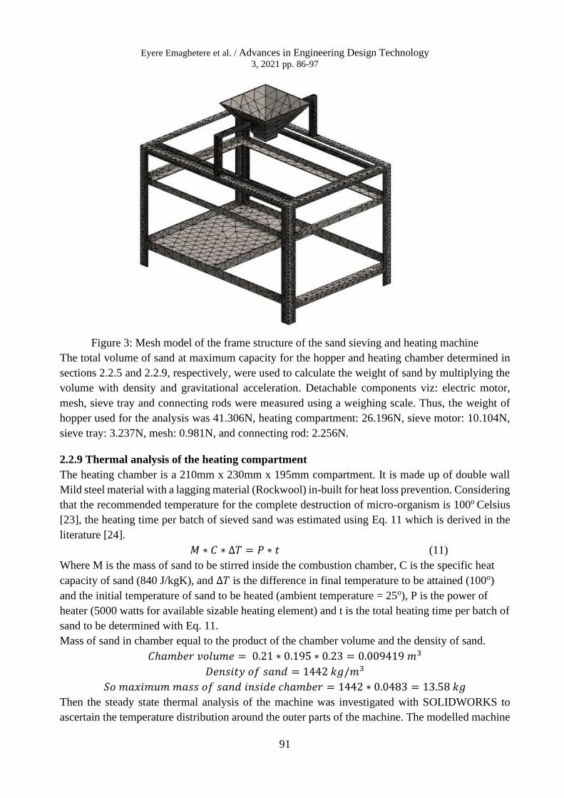
Figure 3: Mesh model of the frame structure of the sand sieving and heating machine
The total volume of sand at maximum capacity for the hopper and heating chamber determined in
sections 2.2.5 and 2.2.9, respectively, were used to calculate the weight of sand by multiplying the
volume with density and gravitational acceleration. Detachable components viz: electric motor,
mesh, sieve tray and connecting rods were measured using a weighing scale. Thus, the weight of
hopper used for the analysis was 41.306N, heating compartment: 26.196N, sieve motor: 10.104N,
sieve tray: 3.237N, mesh: 0.981N, and connecting rod: 2.256N.
2.2.9 Thermal analysis of the heating compartment
The heating chamber is a 210mm x 230mm x 195mm compartment. It is made up of double wall
Mild steel material with a lagging material (Rockwool) in-built for heat loss prevention. Considering
that the recommended temperature for the complete destruction of micro-organism is 100o Celsius
[23], the heating time per batch of sieved sand was estimated using Eq. 11 which is derived in the
literature [24].
𝑀 ∗ 𝐶 ∗ ∆𝑇 = 𝑃 ∗ 𝑡 (11)
Where M is the mass of sand to be stirred inside the combustion chamber, C is the specific heat
capacity of sand (840 J/kgK), and ∆𝑇 is the difference in final temperature to be attained (100o)
and the initial temperature of sand to be heated (ambient temperature = 25o), P is the power of
heater (5000 watts for available sizable heating element) and t is the total heating time per batch of
sand to be determined with Eq. 11.
Mass of sand in chamber equal to the product of the chamber volume and the density of sand.
𝐶ℎ𝑎𝑚𝑏𝑒𝑟 𝑣𝑜𝑙𝑢𝑚𝑒 = 0.21 ∗ 0.195 ∗ 0.23 = 0.009419 𝑚3
𝐷𝑒𝑛𝑠𝑖𝑡𝑦 𝑜𝑓 𝑠𝑎𝑛𝑑 = 1442 𝑘𝑔/𝑚3
𝑆𝑜 𝑚𝑎𝑥𝑖𝑚𝑢𝑚 𝑚𝑎𝑠𝑠 𝑜𝑓 𝑠𝑎𝑛𝑑 𝑖𝑛𝑠𝑖𝑑𝑒 𝑐ℎ𝑎𝑚𝑏𝑒𝑟 = 1442 ∗ 0.0483 = 13.58 𝑘𝑔
Then the steady state thermal analysis of the machine was investigated with SOLIDWORKS to
ascertain the temperature distribution around the outer parts of the machine. The modelled machine

Eyere Emagbetere et al. / Advances in Engineering Design Technology
3, 2021 pp. 86-97
92
was meshed with solid triangular element with a minimum and maximum aspect ratio of 1.129 and
1749.2, respectively. A total of 26255 mesh element and 55059 nodes were formed. Figure 4 shows
the meshed model for the steady state thermal analysis of the machine. Emissivity of the frame and
drying compartment were taken as 0.4, while that of the lagging material was 0.9. A maximum
heater temperature of 160oC was used. This value corresponds to the internal temperature calculated
for an estimated heating time of 5 minutes, using Eq. 11. 5 minutes was chosen to allow for human
errors, should the machine be allowed to continue heating beyond the prescribed 3 minutes, with
the assumption that maximum quantity of heat generated would be transmitted to the stirred sand.
Figure 4: Mesh model for thermal analysis of the sand sieving and drying machine
3.0 Results and Discussion
An exploded view of the sand sieving and drying machine with all its parts indicated is shown in
Figure 5 while Figure 6 shows the isometric view of the design.
Figure 5: An exploded view of the sand sieving and drying machine
Eyere Emagbetere et al. / Advances in Engineering Design Technology
3, 2021 pp. 86-97
93
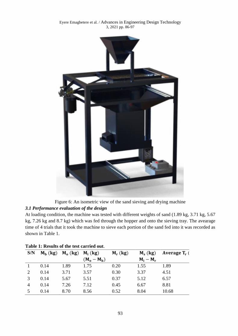
Figure 6: An isometric view of the sand sieving and drying machine
3.1 Performance evaluation of the design
At loading condition, the machine was tested with different weights of sand (1.89 kg, 3.71 kg, 5.67
kg, 7.26 kg and 8.7 kg) which was fed through the hopper and onto the sieving tray. The avearage
time of 4 trials that it took the machine to sieve each portion of the sand fed into it was recorded as
shown in Table 1.
Table 1: Results of the test carried out.
S/N 𝐌𝐛 (𝐤𝐠) 𝐌𝐨 (𝐤𝐠) 𝐌𝐢 (𝐤𝐠)
(𝐌𝐨 − 𝐌𝐛)
𝐌𝐫 (𝐤𝐠) 𝐌𝐬 (𝐤𝐠)
𝐌𝐢 − 𝐌𝐫
𝐀𝐯𝐞𝐫𝐚𝐠𝐞 𝐓𝐫 (𝐌𝐢𝐧𝐬)
1 0.14 1.89 1.75 0.20 1.55 1.89
2 0.14 3.71 3.57 0.30 3.37 4.51
3 0.14 5.67 5.51 0.37 5.12 6.57
4 0.14 7.26 7.12 0.45 6.67 8.81
5 0.14 8.70 8.56 0.52 8.04 10.68

Eyere Emagbetere et al. / Advances in Engineering Design Technology
3, 2021 pp. 86-97
94
where Mo, Mb, Mi, Ms, Mr and Tf are original mass of sand, mass of bucket, mass of sand before
sieving, mass of sand after sieving, mass of sand (impurities) remaining on sieve and time taken to
sieve respectively.
Figure 8: Mass of sieved sand against time of filtration
As observed, the average time of sieve and mass of remnant increased with the quantity of sand
sieved. This is expected, as previous works reported a similar trend [6, 7]. There is a linear
relationship between sieve time (Tr) and the quantity of sieved sand (Ms), having R-square value of
0.9991 when modelled with a linear equation as shown in Figure 8. Thus, the machine has a constant
sieve rate of about 0.7438 which is the slope of the model. More so, it was observed that the more
the weight of sand the higher the impurities left after filtration. Overall, an average of 0.42kg of
impurities was recorded from the five (5) different samples of sand filtered.
Figure 9: Simulation for static modal stress distribution
y = 0.7438x + 0.1215R² = 0.9991
0
1
2
3
4
5
6
7
8
9
0 2 4 6 8 10 12
Siev
ed M
ass
(kg)
Sieve time (Mins)

Eyere Emagbetere et al. / Advances in Engineering Design Technology
3, 2021 pp. 86-97
95
The Von-Mises stress distribution on the machine obtained from statics structural analysis using
SolidWorks is shown in Figure 9. The value of Von-Mises stress is highest in the handle that carries
the hopper, indicating that it is the position that is mostly stressed in the machine and can be
considered to be the most critical point. The frame is the least stressed part of the machine, showing
blue coloration which has the least Von-Mises stress values on the color plot. This is so because the
load the frame bears are uniformly distributed around its members. However, the maximum Von-
Misses stress (16.26 MPa) is less than the yield stress of the material which is 250 MPa, implying
that the machine is not likely to undergo structural failure as discussed in the literature [25].
Figure 10: Simulation for static displacement
The displacements obtained via the static structural analysis with SolidWorks is shown in Figure
10. Although there is not much one can deduce from the obtained distribution of displacements,
the maximum displacements (0.000459mm) which is significantly low informs that the structural
deformations would not likely affect the operation of the machine. Hence, the system can operate
and withstand the maximum load working condition without yielding and significant vibration.
The hopper has the highest displacements as can be observed. This is due to the large mass it may
contain during the operation of the machine. The side frame also has significantly high
displacement, as it bears the load of the sieve tray.
Figure 11 shows the temperature distribution of the sand sieving and heating machine obtained from
the SolidWorks steady state thermal modelling of the machine. As observed, the temperature of the
frame is close to the ambient temperature used for the simulation (25oC), so the frame remains safe
enough for handling during operation of the device. The maximum temperature of the heating

Eyere Emagbetere et al. / Advances in Engineering Design Technology
3, 2021 pp. 86-97
96
chamber was found to be greater than 100o Celsius which is high enough to destroy unwanted micro-
organisms that may be found in sieved sand (World health Organization, 2015). External
temperature in the heating chamber region is shown to be high (greater than 100o), and as thus, not
safe enough for touch during operation. It is important that the machine be heated not more than 3
minutes heating time to avoid excessive rise in temperature, as the difference in external and internal
temperature of the heating chamber is not sufficient for human safety.
Figure 11: Simulation result for steady state heat transfer analysis of the sand sieving and heating
machine
4.0 Conclusion
Conclusively, the sand sieving and drying machine was fabricated and operated successfully and
was able to produce fine and dry sand with negligible vibrations. The design incorporated
components like the sieve tray, the hopper, connecting rods, sieve motor, and the drying
compartment to achieve its set objectives. It is capable of sieving sand at a rate of 0.7438, and the
heating temperature of about 100o Celsius can be obtained within 3 minutes of heating. The machine
at full capacity is capable of producing approximately 8kg of pure and dry sand under 11 minutes.
Finally, the fabricated machine is safe, easy to operate and can be used to produce non-contagious sand of desired
specifications.
References
[1] L. R. Pope and C. W. Ward, "Manual on Test Seiving Methods;," ASTM, vol. 56, 1998.
[2] A. Gupta and D. Yan, "Screening," in Mineral Processing Design and Operations, Elsevier B. V., 2016, pp.
357-419.
[3] R. A. (. 2. 1. Nash, "A Relationship Between Screen Opening and Mesh Size for Standard Sieves," vol. 2, no. 2,
pp. 185-186, 1997.
Eyere Emagbetere et al. / Advances in Engineering Design Technology
3, 2021 pp. 86-97
97
[4] R. Amin, S. Biswas, R. Rahman, J. R. Bhuiyan and S. Rana, "Study and Impact Evaluation of Particle Size
Distribution on Physicochemical Properties of Three Different Tablet Formulations through Sieve Technology,"
International Journal for Pharmaceutical Research Scholars ( IJPRS ), vol. 3, no. 1, pp. 448-563, (2014).
[5] R. Rajapakse, "Soil laboratory testing," in Geotechnical Engineering Calculations and Rules of Thumb, 2nd,
Ed., Elsevier Inc., 2016.
[6] P. C. Bartley, B. E. Jackson and W. C. Fonteno, "Effect of particle length to width ratio on sieving accuracy and
precision," Powder Technology, vol. 355, p. 349–354, 2019.
[7] M. Dıaz-Zorita, J. H. Grove and E. Perfect, "Sieving duration and sieve loading impacts on dry soil fragment
size distributions," Soil & Tillage Research, vol. 94, p. 15–20, 2007.
[8] K. Liu, "Some factors affecting sieving performance and efficiency," Powder Technology , vol. 193, no. 2, p.
208–213, 2009.
[9] Z. Li and X. Tong, "A study of particles penetration in sieving process on a linear vibration screen,"
International Journal of Coal Science & Technology, vol. 2, no. 4, p. 299–305, 2015.
[10] K. Lawinska and R. Modrzewski, " Analysis of sieve holes blocking in a vibrating screen and a rotary and drum
screen.," Physicochem. Probl. Miner. Process, vol. 53, no. 2, p. 812–828, 2017.
[11] M. N. Nwigbo, J. N. Beredam, A. S. Ayodele and H. Itekena, "Fabrication and Performance Evaluation of a
Mechanical Sieve Shaker," International Journal of Engineering and Modern Technology, vol. 3, no. 2, pp. 7-
13, 2017.
[12] S. R. Pawar, S. A. Daunde, E. S. Sonawane and A. C. Dange, "Cam & Follower Operated Multi-Level
Vibrating Screening Machine," International Research Journal of Engineering and Technology, vol. 4, no. 4,
pp. 72-77, 2017.
[13] P. Jadhav, H. Ekal, K. Jambhale and M. Garad, "Design & Fabrication of Multi-level Screening Machine,"
International Journal of Computer Engineering in Research Trends, vol. 5, no. 3, pp. 82-86, 2018.
[14] G. A. Vincent, T. A. D. Bruijn, S. Wijskamp, M. I. Abdul, M. V. Drongelen and R. Akkerman, "Shredding and
sieving thermoplastic composite scrap : Method development and analyses of the fibre length distributions.,"
Composite B, vol. 176, no. June, 2019.
[15] E. Alis, E. I. Ekwue, J. Bridge and R. Birch, "A Three Stack Mechanical Sieve Shaker for determining
Aggregate Size Distribuion of Soils," The West Indian Journal of Engineering, vol. 35, no. 2, p. 36–44, 2013.
[16] N. G. Olaiya, P. K. Oke and P. B. Mogali, "Development of a Multipurpose Mix-sieving Machine," Journal of
Engineering and Engineering Technology, vol. 13, pp. 30-46, 2019.
[17] O. M. Egwuagu and B. N. Nwankwojike, "Design Modification and Comparative Evaluation of Integrated
Grain Slurry Milling and Sieving Machine," International Journal of Scientific & Engineering Research, vol.
10, no. 1, pp. 1130-1134, 2019.
[18] O. E. Simolowo, "Developing Archetypal Machines for a Sequence of Food- Slurry Processing Operations : An
Overview. African Research Review," International Multidisciplinary Journal, Ethopia, vol. 5, no. 22, pp. 122-
136, 2011.
[19] O. A. Ogunwole, "Design , Construction and Testing of a Dry Sand Sieving Machine," J. Appl. Sci. Environ.
Manage, vol. 16, no. 3, p. 241–243, 2012.
[20] R. S. Khurmi and J. K. Gupta, A textbook of Machine Design, New Delhi: Eurasia Publishing House (PVT.)
LTD., 2005.
[21] J. J. Uicker, G. R. Pennock and J. E. Shigley, Theory of Machines and Mechanisms, 5th ed., London: Oxford
University Press, 2016.
[22] M. Greg, M. Dave and J. Jenike, Hopper Design principles, Leads works Press, 2016.
[23] World Health Organization, "World Health Organization Guidelines for drinking water quality," 2015. [Online].
Available: www.who.int//water_sanitation_health/publications/2011/dwq_guidelines/eng. [Accessed 9 October
2021].
[24] R. Knight, B. Jones and S. Field, College Physics: A strategic Approach, 4th ed., Pearson Publishing Co., 2018.
[25] R. G. Budymas, Applied Strength and Applied Stress Analysis, 2nd ed., McGraw Hills Company Inc., 1999.