Design considerations and experimental analysis for silicon carbide power rectifiers
18
Design considerations and experimental analysis for silicon carbide power rectifiers V. Khemka*, R. Patel, T.P. Chow, R.J. Gutmann Center for Integrated Electronics and Electronic Manufacturing, Rensselaer Polytechnic Institute, Troy, NY 12180-3590, USA Received 21 March 1999; accepted 4 May 1999 Abstract In this paper we present the investigation of properties of silicon carbide power rectifiers, in particular Schottky, PiN and advanced hybrid power rectifiers such as the trench MOS barrier Schottky rectifier. Analysis of the forward, reverse and switching experimental characteristics are presented and these silicon carbide rectifiers are compared to silicon devices. Silicon carbide Schottky rectifiers are attractive for applications requiring blocking voltage in excess of 100 V as the use of Si is precluded by its large specific on-resistance. Analysis of power dissipation indicates that silicon carbide Schottky rectifiers oer significant improvement over silicon counterparts. Silicon carbide junction rectifiers, on the other hand, are superior to silicon counterparts only for blocking voltage greater than 2000 V. Performance of acceptor (boron) and donor (phosphorus) implanted experimental silicon carbide junction rectifiers are presented and compared. Some of the recent developments in silicon carbide rectifiers have been described and compared with theory and our experimental results. The well established silicon rectifiers theory are often inadequate to describe the characteristics of the experimental silicon carbide junction rectifiers and appropriate generalization of these theories are presented. Experimental trench MOS barrier Schottky rectifiers (TMBS) have demonstrated significant improvement in leakage current compared to planar Schottky devices. Performance of current state-of-the-art silicon carbide rectifiers are far from theoretical predictions. Availability of high-quality silicon carbide crystals is crucial to successful realization of these performance projections. # 1999 Elsevier Science Ltd. All rights reserved. 1. Introduction Silicon (Si) has been the dominant material for the power semiconductor industry, due to native high quality insulator silicon dioxide (SiO 2 ). No other semi- conducting material can compete if a good high-qual- ity insulating layer is required, i.e. for metal oxide semiconductor (MOS) based devices. Gallium arsenide (GaAs), on the other hand, has been the workhorse of the microwave industry due to its high mobility, high carrier drift saturation velocity and availability of pure and high-quality crystals [1]. However, once the ma- terial is fixed the device performance can only be improved by development of new fabrication tech- niques and/or novel device structures, which is appar- ent with Si and GaAs [2]. With the continuous demand for high current and voltage handling capa- bility and the ability to be able to operate devices at high frequencies and temperatures and in hostile en- Solid-State Electronics 43 (1999) 1945–1962 0038-1101/99/$ - see front matter # 1999 Elsevier Science Ltd. All rights reserved. PII: S0038-1101(99)00155-0 * Corresponding author. Tel.: +1-518-276-6044, fax: +1- 518-276-8761. E-mail address: [email protected] (V. Khemka)
-
Upload
independent -
Category
Documents
-
view
0 -
download
0
Transcript of Design considerations and experimental analysis for silicon carbide power rectifiers

Design considerations and experimental analysis for siliconcarbide power recti®ers
V. Khemka*, R. Patel, T.P. Chow, R.J. Gutmann
Center for Integrated Electronics and Electronic Manufacturing, Rensselaer Polytechnic Institute, Troy, NY 12180-3590, USA
Received 21 March 1999; accepted 4 May 1999
Abstract
In this paper we present the investigation of properties of silicon carbide power recti®ers, in particular Schottky,
PiN and advanced hybrid power recti®ers such as the trench MOS barrier Schottky recti®er. Analysis of theforward, reverse and switching experimental characteristics are presented and these silicon carbide recti®ers arecompared to silicon devices. Silicon carbide Schottky recti®ers are attractive for applications requiring blockingvoltage in excess of 100 V as the use of Si is precluded by its large speci®c on-resistance. Analysis of power
dissipation indicates that silicon carbide Schottky recti®ers o�er signi®cant improvement over silicon counterparts.Silicon carbide junction recti®ers, on the other hand, are superior to silicon counterparts only for blocking voltagegreater than 2000 V.
Performance of acceptor (boron) and donor (phosphorus) implanted experimental silicon carbide junctionrecti®ers are presented and compared. Some of the recent developments in silicon carbide recti®ers have beendescribed and compared with theory and our experimental results. The well established silicon recti®ers theory are
often inadequate to describe the characteristics of the experimental silicon carbide junction recti®ers and appropriategeneralization of these theories are presented. Experimental trench MOS barrier Schottky recti®ers (TMBS) havedemonstrated signi®cant improvement in leakage current compared to planar Schottky devices. Performance ofcurrent state-of-the-art silicon carbide recti®ers are far from theoretical predictions. Availability of high-quality
silicon carbide crystals is crucial to successful realization of these performance projections. # 1999 Elsevier ScienceLtd. All rights reserved.
1. Introduction
Silicon (Si) has been the dominant material for thepower semiconductor industry, due to native high
quality insulator silicon dioxide (SiO2). No other semi-conducting material can compete if a good high-qual-ity insulating layer is required, i.e. for metal oxide
semiconductor (MOS) based devices. Gallium arsenide
(GaAs), on the other hand, has been the workhorse ofthe microwave industry due to its high mobility, highcarrier drift saturation velocity and availability of pure
and high-quality crystals [1]. However, once the ma-terial is ®xed the device performance can only beimproved by development of new fabrication tech-
niques and/or novel device structures, which is appar-ent with Si and GaAs [2]. With the continuousdemand for high current and voltage handling capa-bility and the ability to be able to operate devices at
high frequencies and temperatures and in hostile en-
Solid-State Electronics 43 (1999) 1945±1962
0038-1101/99/$ - see front matter # 1999 Elsevier Science Ltd. All rights reserved.
PII: S0038-1101(99 )00155-0
* Corresponding author. Tel.: +1-518-276-6044, fax: +1-
518-276-8761.
E-mail address: [email protected] (V. Khemka)

vironments, Si and GaAs based electronic systems are
approaching their theoretical limits of device perform-
ance.
Due to the performance limitations of the devices
based on conventional materials, other semiconducting
materials must be considered to satisfy the strong and
increasing needs for high-power, high-frequency, high-
temperature and/or radiation resistant electronics.
Wide bandgap compound semiconductors form the
most attractive alternative because of several outstand-
ing properties. In the past few years, the ®eld of wide
bandgap semiconductors has seen signi®cant research
activity leading to major technological advances mak-
ing them viable for device applications, such as RF
base stations, advanced jet engine control electronics,
combustion control electronics, and ¯ame sensors.
Among these materials, silicon carbide (SiC) has
shown the most promise in terms of availability of
reproducible high quality single crystal wafers and in-
herent electronic properties.
SiC is expected to be a promising candidate not only
for electronic devices operated at high-temperature and
high-power but also for high-frequency microwave
devices. While properties such as large bandgap, high
avalanche electric breakdown ®eld and high thermal
conductivity make SiC a better choice for high-voltage
applications, the large saturation electron drift velocity
is attractive for microwave and millimeter-wave
devices. Also, the large bandgap of SiC provides the
possibility of achieving lower leakage current by sev-
eral orders of magnitude; thus power losses are
reduced, which in turn alleviates device cooling
requirements.
Higher critical ®eld for breakdown allows device de-
sign with higher doping concentration, resulting in
lower speci®c on-resistance; as a result integration of
SiC devices with smaller device size and higher packing
density is possible. One of the most important advan-
tages of SiC over other wide bandgap materials is pro-
cess compatibility with Si. SiC can form silicon oxide
(SiO2) on thermal oxidation and can accommodate
deposited oxide layers to form SiC/SiO2 interfaces,
which may lead to a new era in MOS-based high-
power semiconductor devices.
The superior electronic properties of SiC have been
known for decades. However, device operation at
extreme high-temperatures and high-power conditions
has been demonstrated only recently. Although a var-
iety of prototype small-area SiC power devices have
been realized with record breaking performance in the
past few years, most of them have been produced
using non-optimized device designs and fabrication
Fig. 1. Basic device structures of some common power recti®ers. (a) PiN recti®er, (b) planar Schottky recti®er with guard rings, (c)
trench MOS barrier Schottky (TMBS) recti®er and (d) junction barrier Schottky (JBS) recti®er.
V. Khemka et al. / Solid-State Electronics 43 (1999) 1945±19621946

procedures. The tremendous advantages of SiC tech-nology, as indicated by theoretical predictions, have
not yet been realized, primarily due to the immaturityof SiC device processing technology and the unavail-ability of SiC wafers with low defect densities and
reproducible electrical properties.This paper investigates SiC device technology using
a combination of theoretical modeling, predictions and
experimental results. In particular, trade-o� character-istics of SiC two-terminal power recti®ers are explored.Schottky junctions and PN junctions play a crucial
role in semiconductor device technology, not only fortwo-terminal switching devices, but also because theyform the basic building block of more complicatedthree or four terminal high-power and high-frequency
devices. Knowledge of current conduction mechanismin these junctions is fundamental to most powerdevices.
2. Power recti®ers
The basic device structures of some of the promisingpower recti®ers are shown in Fig. 1. PiN and Schottky
recti®ers are the most common components in powerelectronic systems. High-voltage Schottky recti®erso�er faster switching speed, but su�er from high on-
state voltage drop and on-resistance. PiN recti®ers, onthe other hand, have low forward voltage drop andhigh current conduction capability, but su�er from
poor switching characteristics. The onstate character-istics of the Schottky recti®er and reverse blockingcharacteristics of the PiN recti®er are combined in the
junction barrier controlled Schottky (JBS) recti®er [3].In a JBS recti®er, a P±N junction grid is integrated inparallel with the Schottky junction, thus yielding thelow forward voltage drop of Schottky recti®er during
forward conduction. During reverse blocking the de-pletion layer is pinched-o� under the Schottky contact,thus shielding the Schottky contact from high reverse
bias electric ®elds; a PiN-like reverse characteristics isobtained. Another structure useful in suppressing thehigh leakage current of Schottky recti®er is trench
MOS barrier Schottky (TMBS) recti®er [4]. In this de-sign, a UMOS like trench grid is in parallel with theSchottky barrier. Coupling of MOS gate bias and theelectric ®eld in the mesa region region shields the
Schottky barrier from high reverse bias ®elds and low-ers the leakage current. Both these novel structuresyield signi®cant improvement in the reverse leakage
current with a slight penalty in the forward voltagedrop.As far as process technology is concerned, the
Schottky recti®er is constructed with metal±semicon-ductor junctions whereas the junction recti®er is basedon pn junctions. The device process technology of the
former depends on the Schottky metal as well as sur-face cleaning techniques and postmetal deposition
annealing procedures. By contrast, the junction recti®ercharacteristics are controlled by the pn junction for-mation techniques, the most popular of which are in-
situ doped epitaxy and compensation doping by ion-implantation.Historically, SiC recti®ers have been fabricated using
epitaxial technology due to the better electrical qualityof epitaxial junctions. However, these recti®ers su�erfrom several drawbacks. Apart from loss in surface
planarity, existence of mesa corner and high interfacestate density of the passivation oxide on the trenchsidewall can have detrimental e�ect on the blockingcapability of the device. Use of ion-implanted planar
junction structures can eliminate these problems.However, ion-implantation in SiC carbide is ac-companied by its own drawbacks. Activation of
implanted species typically requires temperatures inexcess of 15008C which generally results in severedegradation and increase in roughness of the SiC sur-
face. Recent results demonstrate that n-type dopants inSiC can be activated at temperatures as low as 12008C[5,6], although activation of p-type implants at low
temperatures remains a problem [7±11].
2.1. Schottky recti®ers
Schottky barrier recti®ers are attractive due to theirfaster switching speed and simple device structure. The
device exhibits extremely fast reverse recovery speedwithout a forward over-voltage transient because theforward current transport occurs primarily via ma-
jority carriers (i.e. minority carrier storage is absent).The device consists of a lightly doped epilayer of thick-ness W on a heavily doped substrate of the same con-ductivity type. The ohmic contact is provided on the
backside of the substrate while the Schottky contact isformed on the front side of the lightly doped epi.Depending on the blocking voltage desired, a suitable
termination scheme may be utilized. The Schottky bar-rier diode is least a�ected by immature device proces-sing and other material qualities such as carrier
lifetime.Parameters typically used to quantify the perform-
ance of a Schottky barrier recti®er are blocking voltage(BV), speci®c on-resistance (Ron), and forward voltage
drop (VF). These parameter are typically determinedby the thickness of the drift layer (W ) and metal±semi-conductor barrier height (FB). An increase in blocking
voltage of the recti®er requires an increase in W, whichunfortunately, degrades the on-resistance and the for-ward voltage drop. The forward voltage drop can be
decreased by utilizing a Schottky metal that o�erslower barrier height, which unfortunately leads to asevere increase in the reverse leakage current. The
V. Khemka et al. / Solid-State Electronics 43 (1999) 1945±1962 1947

Schottky barrier diode in the reverse blocking modealso su�ers from barrier height lowering, which
increases the leakage current signi®cantly as the reversebias is increased.The speci®c on-resistance of a Schottky recti®er can
be written as a sum of the drift layer and substrate re-sistances, Rd and Rsub, respectively,
Ron � Rd � Rsub � Rd � rsubWsub �1�
where rsub and Wsub are the resistivity and thickness ofthe substrate, respectively and the contribution from
the backside speci®c ohmic contact resistivity has beenignored. The speci®c drift layer resistance, Rd can befurther written in terms of the blocking capability (BV)
of the device as [12]
Rd � 4BV2
mEE3c
�2�
where m is the carrier mobility, Ec is the critical ®eldfor breakdown and E is the semiconductor permittivity.Fig. 2 illustrates the Ron versus BV relationship cal-
culated for n-type Schottky recti®ers on Si, 6H±SiCand 4H±SiC. Also shown are the state of the art Ron
versus BV experimental results obtained from pub-lished literature. For the purpose of theoretical calcu-
lation the substrate has been assumed to be 300 mmthick whereas, substrate resistivity has been assumedto be 0.01, 0.03 and 0.015 O cm for Si, 6H±SiC and
4H±SiC, respectively. The electron mobility (mn) in thedrift layer has been taken to be 1000 and 450 cm2/V sfor 4H±SiC and 6H±SiC, respectively. At low values
of BV, Ron is dominated by the substrate resistance.As BV increases, Ron starts to increase due to theincrease in Rd, a direct consequence of the increase in
drift layer thickness. As seen in Fig. 2, although exper-
imental SiC Schottky recti®ers have achieved signi®-
cant improvement over Si counterparts, they are still
far from their theoretical predictions. The highest
blocking voltage achieved, so far, for a 4H±SiC
Schottky diode is 2800 V, reported by Wahab et al.
[13]. However, the reported on-resistance was about 30
mO cm2, an order of magnitude higher than the theor-
etical prediction of 3 mO cm2.
Although, several di�erent metals have been
employed to form Schottky barrier diodes on SiC,
nickel (Ni) and titanium (Ti) are the most commonly
utilized metals [13±25]. Fig. 3 shows the forward
characteristics of the two types of Schottky recti®ers
on 4H±SiC. The Schottky recti®ers are designed for a
blocking capability of 500 V and fabricated on an n/
n+ wafer with 4 mm epilayer. Near ideal characteristics
can be obtained with an ideality factor (n ) of 1.03 and
1.03 and FB of 1.25 and 1.69 eV for Ti and Ni diodes,
respectively. Fig. 3 also illustrates the e�ect of varying
device area on the characteristics. The forward current
is observed to scale with area in the linear region on
the log(J )±V plot, however, in the saturation region
where drop across the series resistance dominates, the
current density is observed to decrease with increase in
area although the current is higher. This anomaly orig-
inates from current spreading in the thick n+ substrate
( 0250±300 mm). Current spreading in the substrate is
more for small area devices resulting in lower forward
voltage drop at a given current density. The current
density can be made to scale back by thinning the sub-
strate or pacakaging the devices as discrete com-
ponents. Nevertheless, measurements on large-area
Fig. 2. Speci®c on-resistance vs. the blocking voltage for
Schottky recti®ers on Si, 6H±SiC and 4H±SiC. Shown are the
experimental results and analytical calculations.
Fig. 3. Forward log(J )±V characteristics of Ti and Ni
Schottky barrier recti®ers on 4H±SiC. The device was
designed to achieve a blocking capability of 500 V with a 4
mm thick drift layer. Also, shown is the e�ect of change in
device area.
V. Khemka et al. / Solid-State Electronics 43 (1999) 1945±19621948

devices will be the true representation of actual currentdensity of the device.The forward voltage drop (VF) of a Schottky recti-
®er is an important parameter and can be written as[26]
VF � nkT
qln� JF
A��T 2� � nFB � RonJF �3�
where k is Boltzmann's constant, q is the electron
charge, T is temperature and JF is the forward currentdensity at VF. A
�� is the Richardson's constant whosevalue is experimentally determined to be 140 A/cm2 K2
using log(J )±V±T measurements and is in good agree-
ment with the theoretically calculated value of 146 A/cm2 K2 [21]. As the breakdown voltage of the Schottkyrecti®er is increased, Ron increases, which in turn
increases the forward voltage drop according to Eq.(3).The calculated forward voltage drop of a 4H±SiC
Schottky recti®er at 100 A/cm2 as a function of thebreakdown voltage is shown in Fig. 4 for di�erent bar-rier heights. VF does not increase up to about a break-down voltage of 2000 V, beyond which a rapid
increase is observed, primarily due to the increase inRon. Also shown on the plot are state-of-the-art exper-imentally reported values of VF at 100 A/cm2. For
high blocking voltage Schottky recti®ers, the exper-imentally achieved values for forward voltage drop arestill short of theoretically predicted values. As the tem-
perature increases, the series resistance contributionfrom the drift region increases because of a decrease inthe mobility, leading to a decrease in VF.
Experimentally we have achieved a VF of 1.79 and1.91 V (at JF 01000 A/cm2) at 25 and 1258C, respect-ively. Current density as high as 9000 A/cm2 has beenachieved with a forward drop of 6.76 V. Although,control of VF is possible by selecting a Schottky metal
with appropriate barrier height, a low F B will increasethe reverse leakage current drastically (thereby increas-ing the o�state losses and power dissipation).
The reverse leakage current of a Schottky recti®er,in a simpli®ed form, includes thermionic emission andimage-force induced barrier lowering and can be writ-ten as [27]
JR � A��T 2 exp
�ÿqkT�FB ÿ DFB�
��4�
where DFB is the image-force induced barrier lowering,which can be expressed in terms of the reverse biaselectric ®eld at the junction (Em) as follows:
DFB �����������qEm
4pE
r�5�
However, the reverse leakage current in a SiC
Schottky diode may not only consist of leakage due tothermionic emission but also ®eld emission, depletionregion generation, edge or surface leakage and defect
related leakage. In addition to these components, ther-mionic emission reverse leakage current is also a�ectedby barrier lowering due to the presence of a thin inter-
facial layer between the metal and the semiconductor.The reverse leakage current in SiC Schottky diodes hasbeen reported to have a larger magnitude than that
Fig. 4. Forward voltage drop, VF versus the breakdown vol-
tage for Schottky barrier recti®ers on 4H±SiC. Shown are the
experimental results and analytical calculations. The forward
drop has been calculated for four di�erent barrier heights at a
current density of 100 A/cm2 and room temperature (300 K).
Fig. 5. Reverse leakage current shown as a function of device
diameter for Ni/4H±SiC Schottky barrier diodes.
Measurements were made on ten devices of each size and
maximum and minimum values are indicated by the error
bars. The device was fabricated on a 3.5 mm thick drift layer.
V. Khemka et al. / Solid-State Electronics 43 (1999) 1945±1962 1949

predicted by Eq. (4) and a stronger voltage dependence
than that given by Eqs. (4) and (5). Bhatnagar et al.
[28] have presented a model to explain the e�ect of
surface inhomogeneities on the reverse current.
Thermionic-®eld emission and ®eld emission can also
have a signi®cant contribution towards the leakage
current. Since the intrinsic carrier concentration of SiC
is extremely small, the depletion region generation
component in the reverse leakage current can be
ignored for all practical purposes.
Fig. 5 illustrates the reverse leakage current of an
unterminated and unpassivated Ni/4H±SiC Schottky
diodes as a function of device diameter at VR equal to
10 and 100 V. At 10 V the data points lie along a
straight line with slope equal to unity, indicating the
domination of perimeter leakages. On the other hand,
at 100 V the data points lie along a line with slope
equal to 2, indicating that the leakage current is pro-
portional to the device area and hence dominated by
bulk leakage. The increase in leakage current in this
region is attributed to the barrier lowering due to the
presence of a thin interfacial layer (typically SiO2)
between the Schottky metal and 4H±SiC surface,
which can sustain a potential drop, yet is thin enough
for tunneling. The thickness of this thin layer is esti-
mated to be about 2 nm using the interfacial layer
thermionic emission model [29]. However, at higher
reverse biases ®eld enhancement at the edge of the
device is expected to control the reverse leakage cur-
rent.
Although progress in the high voltage blocking
capability and forward characteristics of SiC Schottky
recti®ers reported in the past few years is impressive,
investigation into the leakage current mechanism ofSiC Schottky diodes has been minimal. Fig. 6 summar-
izes the measured reverse leakage current of 4H±SiCSchottky diodes at room temperature reported in theliterature. Some of the data quoted in the ®gure, e.g.Refs. [14,18], are near the device breakdown voltage
where avalanche multiplication will have a signi®cantcontribution in increased leakage current. Nevertheless,the leakage current of all SiC high-voltage recti®ers
reported so far are orders of magnitude higher thantheoretical prediction, even with devices having properedge terminations. Surface pretreatment has been
shown to play an important role in SiC Schottky diodecharacteristics, especially in the reverse bias [17].Recently, a large improvement in the leakage current
was achieved on Schottky recti®ers fabricated on 4H±SiC obtained using hotwall CVD technique [13], indi-cating that surface conditions may not be responsiblefor all excess leakage current but that intrinsic material
quality also plays a role.Power dissipation (PD), a critical parameter in
power recti®er operation, depends both on the onstate
loss and the o�state loss according to the relation [26]
PD � JFVFD� JRVR�1ÿD� �6�
where D is the duty cycle and switching losses have
been neglected. Fig. 7 shows the calculated power dis-sipation of a 100 V Schottky diode on Si, 6H±SiC and4H±SiC as function of temperature. The calculations
assume FB=1.0 V, JF=100 A/cm2, VR=20 V andD = 50%. These numbers are typical of siliconSchottky diodes and have been chosen to make a
Fig. 6. Experimentally achieved reverse leakage current den-
sity, as reported in literature, compared to the theoretical
curve predicted by thermionic emission model with barrier
lowering included.
Fig. 7. Power dissipation as a function of temperature for
Schottky recti®er on Si, 6H±SiC and 4H±SiC. The calcu-
lations have been done for a 100 V device with FB=1.0 eV,
JF=100 A/cm2, reverse voltage VR=20 V and duty cycle,
D = 50%.
V. Khemka et al. / Solid-State Electronics 43 (1999) 1945±19621950

direct comparison with SiC. Both 6H± and 4H±SiC
o�er signi®cant improvement in both the power dissi-
pation and maximum device operating temperature.Although, low power dissipation in a Si Schottky recti-
®er can be achieved by suitably designing the barrier
height, a main advantage of SiC Schottky recti®ers
occurs for high reverse voltage operation.
The calculated power dissipation for 6H± and 4H±
SiC 1000 V Schottky diodes for three typical barrier
heights are shown in Fig. 8. The calculations assume
JF=100 A/cm2, VR=500 V and D= 50%. The power
dissipation can be easily lowered by lowering the bar-
rier height, but the maximum operating temperature isalso lowered. For a similar Si device, the power dissi-
pation was estimated to be an order of magnitude
higher thus establishing the advantage of high-voltage
SiC Schottky diodes.
Schottky diodes are also utilized to evaluate the
damage induced by reactive ion etching (RIE). RIE is
employed to form trenches in three terminal devices
such as SITs and MESFETs and can have signi®cant
impact on the device characteristics. Fig. 9 (a) and (b)
illustrates the forward and reverse characteristics ofNi/4H±SiC Schottky diodes that were subjected to
di�erent SiC RIE processes involving ¯uorinated gas
chemistries. A complete detail of the experiment is
reported elsewhere [21]. Although the forward charac-
teristics are degraded with an increase in n and a
decrease in FB, the reverse characteristics of the diodes
are improved after the RIE. The RIE induced thindamaged layer on the surface acts as a passivation
layer, thus reducing the leakage current. Selection of
an appropriate RIE process involves tradeo� between
several parameters such as etch time, etch chemistry,etch rate and Schottky metal.
2.2. PiN recti®ers
PiN recti®ers are useful because of their special cur-rent±voltage characteristics and are the most e�ective
structure in supporting high reverse voltage. The devicestructure consists of a lightly doped drift layer ofthickness W (n-type or p-type) on top of a conductive
substrate of the same conductivity type. A thin heavilydoped layer of opposite conductivity type is created ontop of the drift region either by ion-implantation or
epitaxial growth to provide one contacting terminal,whereas the second contact is to the backside of thesubstrate. The device o�ers extremely low leakage cur-
Fig. 8. Power dissipation as a function of temperature and
barrier height for Schottky recti®er on 6H±SiC and 4H±SiC.
The calculations have been done for a 1000 V device with
JF=100 A/cm2, reverse voltage VR=500 V and duty cycle,
D= 50%.
Fig. 9. The room temperature (a) forward and (b) reverse
log(J )±V characteristics of Schottky barrier diodes fabricate
to examine the e�ect of etch damage. The etch samples were
etched in the above mentioned gas compositions for 5 min
with an rf power of 250 W and a pressure of 20 mTorr. A 1:1
gas ratio was maintained with total gas ¯ow kept at 20 sccm.
The diodes were fabricated on a 3.5 mm thick drift layer.
V. Khemka et al. / Solid-State Electronics 43 (1999) 1945±1962 1951

rent in the reverse bias regime and can be suitablydesigned to provide low forward voltage due to the
conductivity modulation of the drift region. Since cur-rent conduction in PN junctions is fundamental tomost power devices, the mechanisms that govern SiC
PN junction characteristics need to be well character-ized for successful SiC device technology development.For low frequency applications where conduction
losses dominate, the high turn-on voltage in SiC junc-tion recti®ers due to its large bandgap results in ahigher forward voltage drop compared to Si. However,
with increasing switching frequency, the reduced car-rier lifetime in the i layer to improve the switching per-formance causes a rapid increase in the forward dropin Si junction recti®ers. A bipolar switching ®gure of
merit using the frequency ( fmin) at which the totalpower loss in Si device becomes equal to that in widebandgap semiconductor devices was de®ned by Bhalla
and Chow [30]. They showed that SiC and diamondcan o�er performance advantages over Si for high-vol-tage and high-frequency (>10 kHz) applications where
the use of Si is precluded by a large forward drop.
2.2.1. Design considerations
The most important parameters for characterizationof a PiN recti®er are forward voltage drop (VF),reverse recovery current transient and reverse blockingcapability (BV).
The forward voltage drop of a PiN recti®er consistsof the drop across the middle region (Vm) and thedrop across the two end regions or junctions (p+/n(p)
and n+/n(p)) according to
VF � kT
qln�nÿn�n2i
�� Vm �7�
where nÿ and n+ are the electron concentrations at the
two end regions. Accurate estimation of Vm requiresself consistent solution of several transcendentalequations [31]. An estimation of the forward voltage
drop of junction recti®ers of wide bandgap semicon-ductors need to include Auger recombination, carrier±carrier scattering and end-region recombination or the
estimated carrier concentrations are unphysically high.In addition, non-unity injection e�ciency at the pnjunction also needs to be considered. In particular,Auger recombination in the mid-region reduces the
e�ective value of ambipolar di�usion length (La) athigh injection levels, while carrier±carrier scatteringcan reduce the ambipolar di�usion constant at high
injection levels. Thus, diode operation shifts from`short' at low current densities to `long' at high injec-tion levels. Recombination in the end-regions reduces
the fraction of the forward current that is available forconductivity modulation, resulting in an increase inVm.
The best power switch will have high conduction
current density capability with low forward voltage
drop and low leakage current. While wide bandgap
devices are attractive in achieving very low leakage
current density, there is a trade-o� between the onstate
characteristics and switching performance.
Nevertheless, the switching characteristics of wide
bandgap semiconductor junction recti®ers are similar
to that of `short' base diode.
The trade-o� between the on-state voltage drop and
switching speed is qualitatively illustrated in Figs. 10±
Fig. 10. Forward voltage drop (VF) versus breakdown voltage
tradeo� for PiN recti®ers on Si, 6H±SiC and 4H±SiC. Also
shown are the experimental results for 6H±SiC and 4H±SiC
taken from the literature as well as achieved in this work. VF
has been calculated at a forward current density (JF) of 100
A/cm2.
Fig. 11. Forward voltage drop (VF) versus breakdown voltage
trade-o� for PiN recti®ers on Si and 4H±SiC to illustrate the
e�ect of carrier lifetime. VF has been calculated at a forward
current density (JF) of 100 A/cm2.
V. Khemka et al. / Solid-State Electronics 43 (1999) 1945±19621952

12, along with data points experimentally achieved by
us as well as other researchers [32±39]. Fig. 10 shows a
plot of theoretically estimated forward voltage drop at
JF=100 A/cm2 as a function of the device blocking
voltage for Si, 6H± and 4H±SiC. The carrier lifetimes
tn0 and tp0 have been assumed to be equal to 0.1 and
0.01 ms, respectively. These values are compatible with
the high level lifetime (thl) achieved in experimental
reports assuming thl=tn0+tp0. Si junction recti®ers
are superior to SiC recti®ers up to about 2000 V,
beyond which the forward drop in Si devices increases
rapidly while that of SiC devices stay relatively invar-
iant up to about 5000±6000 V. In the ¯at part of the
curve, the forward voltage drop is dominated by the
drop across the end regions as the mid-region drop is
negligibly small due to conductivity modulation and
the small thickness of the i layer. However, as the
breakdown voltage increases, the drop across the mid-
region increases and the device behaves more like a
``long'' diode. In the rapidly increasing part of the
curves the recti®er forward drop is completely domi-
nated by the mid-region voltage drop. Fig. 11 depicts
the e�ect of increase in lifetime on the forward drop of
Si and 4H±SiC devices. An increase in lifetime
improves the on-state drop considerably; however, the
reverse recovery time increases which degrades the
switching performance.
Designing a conductivity modulated junction recti-
®er for low forward voltage drop requires that, to a
®rst order approximation, W/2La is equal to 1.
Theoretical calculations under this assumption reveals
that Si devices are better than SiC devices in terms of
VF even at high voltage (>5000 V) because of the
higher intrinsic turn-on voltage of SiC devices. As a
result Si devices have a performance advantage over
SiC devices in medium power applications. However,the minority carrier lifetime required to satisfy the con-
dition W/2La=1 for Si is approximately two orders ofmagnitude higher than SiC. Since for most bipolarpower recti®ers turn-o� time is typically 2 or 3 times
the lifetime, a Si recti®er for low VF result in a drasticincrease in the switching time. However with a smallerdrift length for SiC devices, the lifetime required to
achieve low on-state voltage drop in SiC recti®ers isvery low even at high voltages. Fig. 12 compares theVF versus lifetime trade-o� curves for 4H±SiC and Si
recti®ers. Low forward voltage drop and high blockingcapability can be easily achieved in SiC recti®ers withlifetime as low as few tens of a nanosecond. For a5000 V Si recti®er, the forward drop shows a rapid
increase for lifetime less than a few ms.Figs. 10±12 also depict the experimental develop-
ments in SiC junction recti®ers in the past few years.
As the quality of the starting material has improved,the device blocking capability has increased and on-state voltage drop has decreased. Singh et al. [39] have
demonstrated 4H±SiC junction recti®ers with record-breaking blocking voltage of 5500 V. The device wasfabricated with a 85 mm thick epi-layer and achieved a
VF of 5.6 V at JF=100 A/cm2. The highest blockingcapability achieved on a 6H±SiC recti®er is 4500 Vachieved by Kordina et al. in 1995 [35]. However,recently the concentration has been more on 4H±SiC
due to its higher carrier mobility. We have recentlyreported 1100 V junction recti®ers in 4H±SiC whichachieved a VF of 3.5 V at JF=100 A/cm2, in good
agreement with the theoretical prediction. The data for1100 V [36] is also plotted in the VF versus ta trade-o�curve using the extracted value of high-level lifetime
from the reverse recovery current transients andassuming ta=thl under high-level injection conditions.The VF of devices fabricated on p+ substrate is signi®-cantly higher than that on n+ substrate due to, as
mentioned earlier, low carrier concentration and highresistivity of the p+ substrates (see Fig. 10).
2.2.2. Characteristics of experimental SiC PiN recti®ersAlthough general Si PiN theory can be applied to
wide bandgap semiconductor power recti®ers to a ®rstorder approximation, an accurate prediction of the rec-ti®er performance can be only obtained by consideringseveral phenomenon which are unique to wide band-
gap semiconductors, in particular SiC. In this sectionwe discuss the performance of experimental SiC powerjunction recti®ers in light of theoretical modeling.
Forward characteristics, reverse characteristics andswitching performance are discussed in that order.Typical forward current conduction according to the
widely accepted Sah±Noyce±Shockley (SNS) modelconsists of di�usion current and recombination currentcomponents. Di�usion current (Jd) originates due to
Fig. 12. Forward voltage drop (VF) versus lifetime tradeo�
curves estimated for 1000 and 5000 V power junction recti®ers
on Si and 4H±SiC.
V. Khemka et al. / Solid-State Electronics 43 (1999) 1945±1962 1953

the recombination of electrons and holes in neutral
regions outside the space-charge region, whereas therecombination current component (Jsc) is due torecombination via single-level, uniformly distributedcenters located at or near the intrinsic level. The cur-
rent±voltage characteristics according to the SNSmodel can be written as
JF � Jsc � Jd � Js1 exp
�qV
2kT
�� Js2 exp
�qV
kT
��8�
where Js1 and Js2 are the saturation current densitiesfor recombination and di�usion current components,respectively. The activation energy obtained by the
Arrhenius plot of Js1 is approximately equal to half ofthe energy bandgap of the semiconductor. However,the above analysis cannot be directly applied to SiC
junctions where experimental results have shown thatJF 0J0 exp(qV/nkT ) and n, the ideality factor, liesbetween 1 and 2. The origin of this discrepancy is due
to the existence of multiple number of deep and shal-low impurity levels in the bandgap of SiC which actsas e�ective recombination sites. A multiple levelrecombination model was formulated and proposed
for wide bandgap compound semiconductors [40±43].We have applied this multiple level model to explainthe forward characteristics of 4H±SiC power junction
recti®ers [34].The multiple level model considers the current in the
1 < n < 2 region as a space-charge recombination cur-
rent but through two groups of arbitrarily-called shal-low and deep levels as illustrated in Fig. 13(a). In thedeep levels group, there are d identical deep sites
located at an average energy level E1 and in the shal-
low levels group there are s identical shallow sites at
an average energy E2. The forward characteristics of
the power recti®ers can now be separated in four
di�erent exponential regimes as shown in Fig. 13(b).
Regions 1 and 2 are similar to that predicted by the
SNS theory but regions 3 and 4 are modi®ed from the
standard theory to include the e�ect of multiple recom-
bination sites. We shall concentrate only on region 2
and 3 as they have been veri®ed experimentally.
The forward characteristics of an experimental 4H±
SiC n+ip+(p+ substrate) recti®er are shown in Fig.
Fig. 13. (a) The energy level of recombination centers for the multiplelevel model and (b) the characteristics of recombination cur-
rent due to multiple level center in the space-charge region.
Fig. 14. Forward log(J )±V characteristics of phosphorus
implanted, 4H±SiC n+ip+ recti®er at room temperature.
Shown are the exponential ®t in the two regions with di�erent
ideality factor (n ).
V. Khemka et al. / Solid-State Electronics 43 (1999) 1945±19621954

14. Regions 2 and 3 are clearly demarcated whereas
region 4 is hard to separate due to the series resistancedrop. According to the multiple level model the ®rstterm in the SNS current (Eq. (8)) is expanded to
include the contribution from multiple recombinationsites and can be rewritten as
Jsc � J01 exp
�qV
2kT
�� J02 exp
�qV
nkT
��9�
where ideality factor n has been related to the numberof recombination sites by [41]
n � s� 2d
s� d�10�
For the single recombination level case (s = 0,d= 1),
we obtain n = 2 and the multiple level model reducesto the SNS model. In this model n is temperature inde-pendent. Consider the di�erential ideality factor (nd)
obtained by di�erentiating the total current given byEqs. (8) and (9):
nd ��a1 � a2
2
� a1 ÿ a22
tanh�a1 ÿ a2��qVÿ qVB�
2kT
�ÿ1�11�
where a1=1/2, a2=1/n, VB is the cross-over voltagebetween the two current regions as shown in Fig. 14and any contribution from di�usion current has been
ignored for the sake of simplicity. The plot of nd versusqV/kT shifts along the qV/kT axis with temperature,while the shape of the plot is retained. This relation-
ship provides a unique way of determining the correct
value of ideality factor.An experimental demonstration of the above method
is illustrated in Fig. 15. Unlike theoretical curves, the
experimental data increases after the minimum pointdue to the series resistance drop. The ideality factor
obtained from the multiple-level analysis was obtainedto be 6/5, indicating that the recombination processesinvolve 4 shallow levels (s ) and 1 deep level (d ). The
theoretical value of n is slightly lower than the exper-imentally obtained value of 1.28 which is attributed tohigh current e�ects such as ®eld crowding and series
resistance voltage drop. The thermal activation ener-gies EA1 and EA2 associated with the two saturation
current densities J01 and J02 were determined to be1.65 and 2.71 eV, respectively. These numbers are ingood agreement with the values predicted by the SNS
and multiple-level models which predict the two acti-vation energies to be Eg/2 and Eg/n, respectively,where Eg=3.26 eV and n= 6/5.
Although, the quality of experimental SiC junctionrecti®ers has improved considerably in recent years,
forward characteristics still su�er from several undesir-able phenomenon originating from intrinsic materialproperties. One key phenomena is the current con-
trolled negative resistance (CCNR) observed recentlyin both 6H± and 4H±SiC junction recti®ers [44]. Theorigin of this phenomenon is attributed to the inability
of the device to enter the double injection regime andhence the lack of conductivity modulation in the drift
region. The device can be forced from single to doublecarrier injection regime by applying su�ciently highforward bias. Once the device enters double injection
regime, forward current density increases drastically.The existence of CCNR was attributed to the chargetrapping; the possibility of eliminating CCNR by ®lling
the traps was achieved by storing the device under for-ward bias at high temperature (1508C) for a long
period of time [44].Reverse characteristics of experimental SiC PiN rec-
ti®ers have also fallen short of theoretical prediction
with the reverse leakage current orders of magnitudehigher than that indicated by standard diode theory.
The key reason for high leakage current in these recti-®ers has been material defects such as micropipes.Improvement in material quality have led to improve-
ment in SiC PiN reverse leakage current, with exper-imental devices having signi®cantly lower leakagecurrent than Si counterparts.
The reverse log(J )± (V ) of a small-area (4 � 10ÿ4
cm2), 4H±SiC, boron-implanted, P+iN+ device fabri-
cated with a 10 mm i layer (n-type with ND=1.8 � 1016
cmÿ3) is shown in Fig. 16 (high voltage measurementbeyond 1008C were prevented by surface ¯ashover). A
reverse current density of about 5 � 10ÿ6 A/cm2 wasmeasured at a reverse bias of 900 V, an order of mag-
Fig. 15. The di�erential ideality factor (nd) versus the normal-
ized junction voltage at room temperature and 1008C for
phosphorus implanted, 4H±SiC n+ip+ recti®er. Theoretical
curves have been calculated with n= 6/5.
V. Khemka et al. / Solid-State Electronics 43 (1999) 1945±1962 1955

nitude lower than that reported by Holzlein et al. [45].
Their boron-implanted diodes fabricated on 10 mm,2 � 1016 cm3 n-type epitaxial layer indicated a leakagecurrent of about 5 � 10ÿ5 A/cm2 at 900 V. However,
our leakage currents are somewhat higher than thebest data reported by Mitlehner et al. [38] for Al-implanted 4H±SiC diodes. The reverse current densitywas found to vary as the square root of the reverse
voltage, indicating that a space charge generationreverse current may be present.The generation current (Jgen) in terms of e�ective
generation lifetime (tg,e�) can be written as
Jgen�T � � q
����������2EqNB
s �ni�T �
tg,eff�T �� ����
Vp
�12�
where q is the electron charge, ni(T ) is the intrinsic car-
rier concentration at temperature T, NB is the driftlayer doping concentration and V is the applied reversebias. Assuming a lower bound to the expected gener-ation lifetime (100 ns), the theoretically calculated gen-
eration reverse current density was found to be ordersof magnitude lower than the experimentally observedvalue, indicating that generation current can not be the
dominating current mechanism in these diodes. Surfacee�ects and perimeter leakages are assumed to be re-sponsible. Measurement at 508C did not yield any
change in the reverse current at high reverse biases,however, at 1008C the reverse current density increasedto 01 � 10ÿ5 A/cm2 at 900 V.
Reverse characteristics of large area devices(4 � 10ÿ2 cm2) indicated signi®cantly low current den-sity, although the current was higher, which indicatesthat the reverse leakage current is dominated by per-
ipheral leakage. This was con®rmed by measuringreverse leakage current at a reverse bias of 100 V as a
function of device size. As depicted in Fig. 17, a linear
relationship between the leakage current and deviceperimeter to area ratio is observed, both at room tem-perature and 1008C, indicating the signi®cance of per-
imeter leakages. At a reverse bias of 100 V, the reverseleakage current density, at room temperature, asmeasured on small-area and large-area device was
01 � 10ÿ6 and 07 � 10ÿ8 A/cm2, respectively.Although the large area diodes achieved an order ofmagnitude lower current density than the small area
devices at low reverse biases (R100 V), their break-down voltage was observed to be much lower ( 0200±
Fig. 18. Reverse log(J )±V characteristics of phosphorus
implanted, 4H±SiC n+ip+ recti®er at di�erent temperatures.
Fig. 17. Reverse leakage current at 100 V for planar, boron
implanted, 4H±SiC p+in+ recti®ers as a function of device
perimeter to area ratio. The linear relationship at two di�er-
ent temperatures (25 and 1008C) indicate the signi®cant of
perimeter leakage current component.
Fig. 16. Reverse log(J )±V characteristics of planar, boron
implanted, 4H±SiC p+in+ recti®er at di�erent temperatures.
V. Khemka et al. / Solid-State Electronics 43 (1999) 1945±19621956
300 V), which is believed to be a direct consequence ofhigher number of defects present.
The reverse characteristics of small-area, 4H±SiC,phosphorus implanted, n+ip+ type recti®er fabricatedon a 4 mm thick p-type i layer are shown in Fig. 18.
Leakage current as low as 02 � 10ÿ9 A/cm2 isobtained. The reverse leakage current is relatively inde-pendent of reverse bias for up to about 300 V, beyond
which it increases due to pre-avalanche multiplication.The constant leakage current is believed to be contrib-uted by implant damage-induced leakage current. This
leakage current is independent of bias because thedamage regions that cause excessive leakages arelocated in the heavily doped N+ side of the junctionwhere the expansion of the depletion region is almost
negligible.Space charge limited (SCL) current has also been
observed in SiC power recti®ers which has been
demonstrated to be trap-induced [46]. In this case, thereverse characteristics follow a more generalized J±Vn
relationship, where n can lie between 2 and 5. This
characteristic was believed to be due to the presence ofa ¯aw that shorts through the pn junction, the socalled `bluespot' [47]. The bluespot acts as a remote
anode contact that originates carrier injection in theepitaxial region; SCL current is observed when thedensity of excess electrons introduced by electric ®eldis larger than the thermally generated electrons.
Switching performance of the SiC power recti®ershave been analyzed by measuring the reverse recoverycurrent transient curve using a custom-built test circuit
[48]. The reverse recovery is a major performance limi-tation of power recti®ers, especially for high-frequencyapplications because of increased switching losses.
Therefore, optimization of the device design to yieldminimum reverse recovery time while maintaininggood on state characteristics is necessary.Carrier lifetime in the drift region is estimated from
reverse recovery current waveform by solving thecharge control equation given as
dQ�t�dt� Q�t�
thl
� i�t� �13�
where Q(t ) is the instantaneous minority carrier chargein the drift region, i(t ) is the instantaneous terminalcurrent during switching and thl is the high level life-
time. A common way of solving the above equationinvolves approximating the current i(t ) with a triangu-lar waveform, which can give reasonable results pro-
vided that the ramp rate is su�ciently high comparedto the lifetime. However, this condition is hardly metin current state-of-the-art SiC power recti®ers due to
short lifetime, smaller current conduction capabilityand high on-resistance.To minimize the error in lifetime extraction we ap-
proximate the ®rst part of i(t ), 0r tr t1 (see Fig. 19)by higher degree (m ) polynomials according to
i�t� �Xmp�0
aptp, 0rtrt1 �14�
The solution of Eq.(14) can then be written as follows,with Q(0ÿ)=IFthl:
Q�t� �"IFthl �
Xmp�0
Ap�ÿthl� p�1#
eÿt=thl �Xmp�0
t p
p!"Xmq�p
Aptqÿp�1hl �ÿ1�qÿp
# �15�
where Ap=app! and IF is the forward current. Finally,thl can be obtained by solving Eq. (15) subjected to the
charge continuity: Q(t1ÿ)=Q(t1
+), where Q(t1+) is the
remaining charge in the device at t=t1 and is deter-mined by numerical integration of the measured wave-
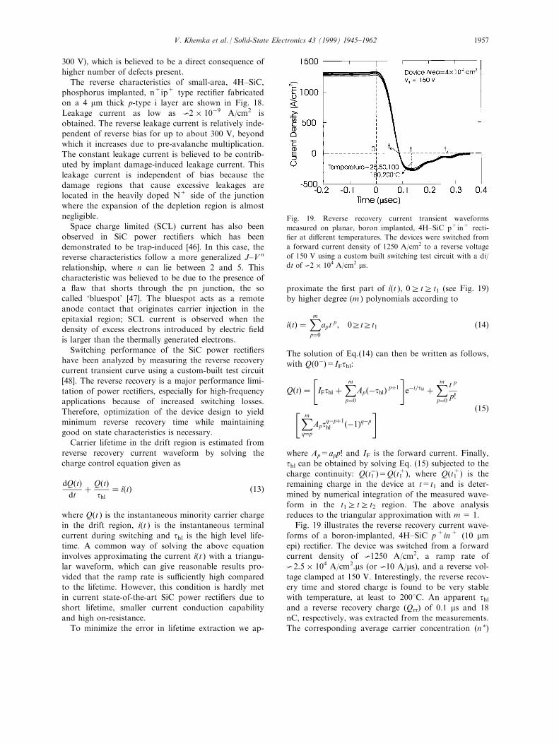
form in the t1r tr t2 region. The above analysisreduces to the triangular approximation with m = 1.Fig. 19 illustrates the reverse recovery current wave-
forms of a boron-implanted, 4H±SiC p+in+ (10 mmepi) recti®er. The device was switched from a forwardcurrent density of 01250 A/cm2, a ramp rate of
02.5 � 104 A/cm2.ms (or 010 A/ms), and a reverse vol-
tage clamped at 150 V. Interestingly, the reverse recov-ery time and stored charge is found to be very stablewith temperature, at least to 2008C. An apparent thland a reverse recovery charge (Qrr) of 0.1 ms and 18nC, respectively, was extracted from the measurements.The corresponding average carrier concentration (n �)
Fig. 19. Reverse recovery current transient waveforms
measured on planar, boron implanted, 4H±SiC p+in+ recti-
®er at di�erent temperatures. The devices were switched from
a forward current density of 1250 A/cm2 to a reverse voltage
of 150 V using a custom built switching test circuit with a di/
dt of 02 � 104 A/cm2 ms.
V. Khemka et al. / Solid-State Electronics 43 (1999) 1945±1962 1957

during the on-state, estimated by assuming a uniformcarrier distribution inside the i layer, was 04 � 1017
cmÿ3, which indicates strong conductivity modulationin the drift region with a doping of 1 � 1016 cmÿ3.Assuming an ambipolar di�usion constant (Da) of
about 5 cm2/s, the ambipolar di�usion length (La) isdetermined to be about 7 mm. A more accurate esti-mate of La would require inclusion of carrier±carrier
scattering, which causes Da to decrease rapidly at highlevel injections and has been ignored in the presentanalysis. A similar analysis, with JF=500 A/cm2 on
phosphorus-implanted, 4H±SiC, n+ip+ (4 mm epi) rec-ti®er indicated a thl and Qrr of 0.15 ms and 12 nC, re-spectively; n � in this case, was 07 � 1017 cmÿ3.Under high level injection condition the e�ective
high level lifetime can be written in terms of its com-ponents according to the relation
1
teff,hl
� 1
tSRH,hl
� 1
trad,hl
� 1
tauger,hl
� 1
ta
� Bn 0 � gn 02 �16�
where tSRH,hl is the Shockley±Read±Hall (SRH)recombination lifetime, n ' is the carrier concentration,B is the radiative recombination coe�cient and g is theAuger recombination coe�cient. The second term in
Eq. (16) is the radiative lifetime term. Electron±holepairs recombine from band to band with the energycarried away by photons. The third term is contributed
by the Auger recombination e�ects which dominatethe behavior of minority carrier lifetime at high injec-tion levels. Radiative recombination is typically im-
portant at moderate injection levels whereas Auger
recombination is the ultimate recombination mechan-
ism at high injection levels. It is clear that a log(te�,hlÿ1 )±
log(n ') will have a slope of 2 at very high injectionlevels and can be utilized to calculate g.Fig. 20 shows the above plot for three di�erent 4H±
SiC junction recti®ers. The log(te�,hlÿ1 )±log(n ') relation-
ships obtained in this experiment clearly indicate thedomination of Auger recombination at high current
injection levels (>100 A/cm2). The Auger coe�cientwas estimated to be about 4±7 � 10ÿ30 cm6/s. Theradiative recombination coe�cient can not be deter-
mined due to the small measurement range. Note thatwe have assumed a uniform current ¯ow in our model.Actually, the Auger recombination may not dominate
over the entire device due to current ®lamentation, i.e.current conduction through a relatively small cross-sec-tion like micropipe defects or other inhomogeneity.As explained earlier, the trade-o� between forward
voltage drop and switching speed is important inpower junction recti®ers because the design parametersthat can be changed to improve either parameter
almost always degrade the other. Fig. 21 illustrates thetrade-o� curve measured on three di�erent 4H±SiCjunction recti®ers, indicating that p+in+ recti®ers give
the best performance with low forward voltage drop.The data points were generated by varying the forwardcurrent density. With an increase in JF or the injectionlevel the carrier lifetime is observed to decrease due to
the contribution from radiative and Auger recombina-tion.The reverse recovery current transient behavior is
considerably di�erent in p+i(n)n+ type and n+i(p)p+
type power recti®ers. Fig. 22 illustrates the recovery
Fig. 21. Measured carrier lifetime versus forward voltage drop
trade-o�s. The lifetime values were extracted using measure-
ment similar to that indicated in Fig. 19. The boron
implanted p+in+ recti®er have a better trade-o� curve than
that of phosphorus implanted recti®ers fabricated on p+ sub-
strates.
Fig. 20. te�ÿ1 as a function of the carrier concentration (n ').
The te�ÿ1 0n '2 relationship indicates the domination of Auger
processes at high level injection.
V. Khemka et al. / Solid-State Electronics 43 (1999) 1945±19621958

characteristics of p- and n-type 4H±SiC power recti-®ers, indicating that the recovery process in the p-typedevice is faster than that in the n-type. Physically, thesituation is unchanged at high forward currents, wherethe carrier concentration exceeds the doping level of
drift region due to conductivity modulation. However,as the device switches from forward to reverse mode, aspace-charge voltage builds up which is dominated bythe drop across the junction with dissimilar conduc-
tivity (the drop across the junction comprising similarconductivity can be ignored due to the ohmic beha-vior). The space-charge region develops in the n(n)typedrift region whereas, in the other case it develops inthe p(n)type drift layer. Due to the di�erence in elec-tron and hole mobilities and accounting for the fact
that, both devices must sweep out the same amount ofstored charge for full recovery (assuming similardimensions and lifetimes in the drift region), the
reverse current in the p-type device terminates fasterthan that in n-type device. A snapping factor, S=tB/tA(tB=t2t1 and tA=t1t0 in Fig. 19) quanti®es the di�er-ence in the recovery process of the two types of
devices; S is 04 and 07 for the p- and n-type devices,respectively.
2.3. Advanced power recti®ers
In order to achieve good reverse blocking character-istics while maintaining Schottky-like good forward
conduction characteristics, several modern recti®erssuch as junction barrier Schottky (JBS) [3], dual metaltrench (DMT) [14] and trench MOS barrier Schottky
(TMBS) [4] have been explored. Although these devicesoperate with a slightly di�erent mechanism in the for-ward direction, the design concepts used to reduce the
leakage current are similar, i.e. to completely deplete
the mesa region under the Schottky contacts so as to
prevent the Schottky junction from exposure to high
reverse bias electric ®elds. Merged PiN Schottky
(MPS) recti®ers have also been proposed to improve
the reverse recovery of the junction recti®er [49].
While both JBS and MPS recti®ers have similar
device structures with deep implanted interdigitated p+
grid adjacent to Schottky junctions, the main junction
in the MPS recti®er is the pin diode region. The p+
grids in MPS recti®ers are designed to inject holes into
the drift region, which results in a drastic reduction in
the series resistance via conductivity modulation. Also,
the auxiliary Schottky regions are placed next to the
pn junctions so as to reduce reverse peak current and
to speed up reverse recovery. Since the injection level
in MPS is not as high as PiN recti®ers, the stored
charge is lower and allows faster and softer reverse
recovery. Both MPS and JBS recti®ers have been
reported in SiC [15,23]. Although these reported
devices achieved breakdown voltages as high as 1000
V, more work is needed to realize the full advantage of
the concept.
The DMT recti®er reported recently [14] utilizes
metals with two di�erent barrier heights to achieve
similar performance as mentioned above. The reported
device had Ti deposited to achieve a low barrier height
on top of the mesa followed by conformal deposition
of Ni over the entire device to achieve high barrier
height at the bottom of trenches. The forward drop
and reverse leakage current reported for this device
Fig. 22. Recovery characteristics of p- and n-type diodes in
4H±SiC. In both the cases devices are switched from a for-
ward current density of 1250 A/cm2 to a reverse voltage of
150 V.
Fig. 23. Forward and reverse characteristics of trench MOS
barrier Schottky (TMBS) recti®ers (Schottky metal is Ni)
compared to that of a planar Ni Schottky and planar
implanted PiN recti®er in 4H±SiC. The TMBS characteristics
are measured for two di�erent percentage Schottky areas
(a= 40% and 57%).
V. Khemka et al. / Solid-State Electronics 43 (1999) 1945±1962 1959

were between Ti and Ni-Schottky Barrier Diodes(SBDs). In particular, a forward voltage drop close to
that of Ti SBD but with leakage current two orders ofmagnitude lower than Ti SBD and about a factor oftwo higher than Ni SBD. Although the leakage current
measurements were shown up to a reverse voltage of300 V, no information on the true breakdown voltageof the device was given.
Embedding a UMOS trench like grid instead of aPN junction grid as in JBS/MPS recti®ers yields astructure known as the TMBS recti®er. The original Si
device reported in Ref. [4] was shown to be capable ofachieving higher than parallel plane breakdown voltagewith little compromise in the forward conduction capa-bility. Forward and reverse characteristics of a polysili-
con planarized Ni-TMBS in 4H±SiC, for two di�erentpercentage Schottky areas (a = 40% and 57%), arecompared to that of simultaneously fabricated Ni SBD
and PiN recti®ers in Fig. 23. A signi®cant improve-ment over the SBD leakage current is observed withlittle sacri®ce in the forward voltage drop. The reverse
leakage current and forward voltage drop, as expected,were observed to scale with the percentage Schottkyarea. An increase in mesa width reduces the amount of
®eld shielding under the Schottky contact whileincreasing the percentage Schottky area. Both e�ectscombined result in an increased leakage current andreduced forward voltage drop. Depth of the trench
would also alter the device performance signi®cantly asthe aspect ratio is directly altered thereby a�ecting the®eld shielding under the Schottky mesa. Thus, an opti-
mized device design involves a careful selection ofmesa width and trench depth. A detailed fabricationprocess along with design and experimental analysis
will be presented elsewhere ant.
3. Summary
We have presented a detailed investigation of some
of the common SiC power recti®ers resulting from sig-ni®cant research in the ®eld of SiC power devices overthe last decade. With a particular semiconductor, the
choice of whether a Schottky-based recti®er or a junc-tion recti®er should be used for any applicationdepends on the blocking voltage, current density,switching frequency and operating temperature. For
high frequency applications, the Schottky recti®er isalways preferred for the lack of minority carrier sto-rage, while the junction recti®er is the choice for high-
temperature and high-voltage application due to lowleakage current. A direct comparison of Si and SiCjunction recti®ers reveals that Si recti®ers are superior
to SiC recti®ers requiring blocking voltage capabilityless than about 2000 V due to their low forward vol-tage drop; however, SiC devices exhibit faster reverse
recovery than Si junctions. Similarly, Si Schottkydiodes are better than SiC up to about a blocking vol-
tage of 100 V. Comparison of SiC Schottky diodeswith PiN recti®ers indicates that high turn-on voltageof SiC junction recti®ers make them uncompetitive
below 04000 V or below 100 A/cm2. On the otherhand, at higher blocking voltages or in applicationswhere a high overcurrent conditions may exist, the
conductivity modulated PiN recti®ers are superior.Several state-of-the-art reported recti®er data along
with our experimental results are compared to the
theoretical calculations. The comparison indicates that,although SiC device technology has developed signi®-cantly in recent years the experimental results are stillfar from theoretical predictions. Material imperfections
such as micropipes and other defects are responsiblefor undesirable device characteristics such as CCNR.Because of several unique properties of SiC, standard
Si junction diode theory can not be applied directlywithout signi®cant modi®cation. The characteristics ofSiC junction recti®ers have been shown to be governed
by generalized SNS model or multiple-level model.Advanced power recti®ers such as JBS and TMBS arealso attractive for high-voltage and high-power appli-
cations due to their ability to combine best feature ofSBD and PiN recti®er. We have demonstrated a sig-ni®cant improvement in the leakage current of SBD byutilizing a TMBS type of structure.
Considering the stage of SiC development, mosthigh-temperature and high-power electronics of thefuture are expected to utilize SiC devices. However,
signi®cant advancement in material growth, dopingand contact technology must be made in order toacquire the potential payo� from SiC devices. If high
quality SiC crystals can be produced, signi®cantimprovement in the voltage and power handling capa-bility of rectifying two-terminal devices can beachieved by proper design and fabrication.
Acknowledgements
The authors gratefully acknowledge the ®nancialsupport by the Philips Research Laboratories,Briarcli� Manor, NY, the MURI of the O�ce of
Naval Research under Grant No. N00014-95-1-1302(sub-contracted from Purdue University) and DARPAunder grant No. MDA 972-98-C-0001 (sub-contracted
from GE CR&D). We would also like to thankNorthrop-Grumman and GE CR&D for technical sup-port.
V. Khemka et al. / Solid-State Electronics 43 (1999) 1945±19621960

References
[1] Ladbrooke PH. MMIC design: GaAs FETs and
HEMTs. Boston, USA: Artech House, 1989.
[2] Ghandhi SK. VLSI fabrication principles: silicon and
gallium arsenide. New York: John Wiley and Sons, 1994.
[3] Baliga BJ. The pinch recti®er: a low forward drop, high
speed power diodes. IEEE Electron Device Lett
1984;5:194±6.
[4] Mehrotra M, Baliga BJ. Trench MOS barrier Schottky
(TMBS) recti®er. Solid State Electron 1995;38:703±13.
[5] Pan JN, Cooper Jr JA, Melloch MR. Activation of nitro-
gen implants in 6H±SiC. J Electron Mater
1997;26(3):208±11.
[6] Khemka V, Patel R, Ramungul N, Chow TP, Ghezzo
M, Kretchmer J. Characterization of phosphorus implan-
tations in 4H±SiC. J Electron Mater 1999;27(10):1128±
35.
[7] Capano MA, Ryu S, Melloch MR, Cooper Jr JA, Buss
MR. Dopant activation and surface morphology of ion
implanted 4H and 6H±silicon carbide. J Electron Mater
1997;27(4):370±6.
[8] Rao MV, Gri�ths P, Gardner J, Holland OW, Ghezzo
M, Kretchmer J, Kelner G, Freitas JA. Al, Al/C and Al/
Si implantations in 6H±SiC. J Electron Mater
1996;25(1):75±80.
[9] Kimoto T, Itoh A, Matsunami H, Nakana T, Watanabe
M. Aluminum and boron ion implantations into 6H±SiC
epilayers. J Electron Mater 1996;25(5):879.
[10] Takemura O, Kimoto T, Matsunami H, Nakata T,
Watanabe M, Inoue M. Implantation of Al and B accep-
tors into alphaSiC and pn junction diodes. In: Proc. of
the Int. Conf. on SiC, III-N and Related Materials,
1997, Stockholm, Sweden, 1997:701±704.
[11] Ramungul N, Khemka V, Zheng YP, Patel R, Chow TP.
6H±SiC p+n junctions fabricated by beryllium implan-
tation. IEEE Trans Electron Devices 1999;46(3):465±70.
[12] Baliga BJ. Power semiconductor device ®gure of merit
for high-frequency applications. IEEE Electron Device
Lett 1989;10:455±7.
[13] Wahab Q, Kimoto T, Ellison A, Hallin C, Tuominen M,
Yakimova R, Henry A, Bergman JP, Janze n E. A 3 kV
Schottky barrier diode in 4H±SiC. Appl Phys Lett
1998;72(4):445±7.
[14] Schoen KJ, Woodall JM, Cooper JA, Melloch MR.
Design considerations and experimental analysis of high-
voltage SiC Schottky barrier recti®ers. IEEE Trans
Electron Devices 1998;45(7):1595±2004.
[15] Dahlquist F, Zetterling CM, OÂ stling M, Rottner K.
Junction barrier Schottky diodes in 4H±SiC and 6H±
SiC. In: Proc. of the Int. Conf. on SiC, III-N and
Related Materials, 1997, Stockholm, Sweden, 1997:106±
164.
[16] Saxena V, Steckl AJ. High voltage 4H±SiC recti®ers
using Pt and Ni metallization. In: Proc. of the Int. Conf.
on SiC, III-N and Related Materials-1997, Stockholm,
Sweden, 1997:937±940.
[17] Alok D, Eglo� R, Arnold E. E�ect of surface prep-
aration and thermal anneal on electrical characteristics of
4H±SiC Schottky barrier diodes. In: Proc. of the Int.
Conf. on SiC, III-N and Related Materials, 1997,
Stockholm, Sweden, 1997:929±932.
[18] Mitlehner H, Bartsch W, Bruckmann M, Dohnke KO,
Weinert U. The potential of fast high voltage SiC diodes.
In: IEEE Int. Symp. Power Semicond. Dev. ICs,
Weimer, Germany, 1997:165±168.
[19] Raghunathan R, Alok D, Baliga BJ. High voltage 4H±
SiC Schottky barrier diodes. IEEE Electron Device Lett
1995;16(6):226±8.
[20] Itoh A, Kimoto T, Matsunami H. Low power loss 4H±
SiC Schottky recti®ers with high blocking voltage. In:
Proc. of the Int. Conf. on SiC and Related Materials,
1995, Kyoto, Japan, 1995:689±692.
[21] Khemka V, Chow TP, Gutmann RJ. E�ect of reactive
ion etchinduced damage on the performance of 4H±SiC
Schottky barrier diodes. J Electron Mater
1998;27(10):112±835.
[22] Khemka V, Ananthan A, Chow TP. A fully planarized
4H±SiC trench MOS barrier Schottky (TMBS) recti®er.
In: IEEE Int. Symp. Power Semicond. Dev. ICs,
Toronto, Canada, 1999:165±68.
[23] Held R, Kaminski N, Neimann E. SiC merged pn/
Schottky recti®ers for high voltage applications. In: Proc.
of the Int. Conf. on SiC, III-N and Related Materials,
1997, Stockholm, Sweden, 1997:1057±1060.
[24] Schoen KJ, Henning JP, Woodall JM, Cooper Jr. JA,
Melloch MR. A dualmetal trench (DMT) Schottky pin-
chrecti®er in 4H±SiC. In: Proc. of the Int. Conf. on SiC,
III-N and Related Materials, 1997, Stockholm, Sweden,
1997:945±948.
[25] Singh R, Palmour JW. Planar terminations in 4H±SiC
Schottky diodes with low leakage and high yields. In:
IEEE Int. Symp. Power Semicond. Dev. ICs, Weimer,
Germany, 1997:157±160.
[26] Baliga BJ. Modern power devices. New York: John
Wiley and Sons, 1994.
[27] Rhoderick EH, Williams RH. Metal±semiconductor con-
tacts, 2nd ed. Oxford: Clarendon, 1988.
[28] Bhatnagar M, Baliga BJ, Kirk HR, Rozgonyi GA. E�ect
of surface inhomogeneities on the electrical character-
istics of SiC Schottky contacts. IEEE Trans Electron
Devices 1996;43(1):150±6.
[29] Wu C-Y. Interfacial layer thermionic di�usion theory for
the Schottky barrier diode. J Appl Phys 1982;53(8):5947±
50.
[30] Bhalla A, Chow TP. Bipolar power device performance:
dependence on materials, lifetime and device rating. In:
Silicon Carbide and Related Materials: Proc. of 5th Int.
of Phys. Conf, series-137, 1993:621±623.
[31] Ghandhi SK. Semiconductor power devices. New York:
John Wiley and Sons, 1977.
[32] Kordina O, Bergman JP, Henry A, Janzen E, Savage S,
Andre J, Ramberg LP, Lindefelt U, Hermansson W,
Bergman K. A 4.5 kV silicon carbide recti®er. Appl Phys
Lett 1995;67:1561.
[33] Shenoy PM, Baliga BJ. Planar, high voltage, boron
implanted 6H±SiC PN junction diodes. In: Proc. of the
Int. Conf. on SiC and Related Materials, 1995, Kyoto,
Japan, 1995:717±720.
[34] Patel R, Khemka V, Ramungul N, Chow TP, Ghezzo
M, Kretchmer J. Phosphorus-implanted high-voltage
V. Khemka et al. / Solid-State Electronics 43 (1999) 1945±1962 1961

4H±SiC N+P junction recti®ers. In: International
Symposium on Power Semiconductor Devices and ICs,
Kyoto, Japan, 1998:387±390.
[35] Fedison J, Li Z, Ramungul N, Chow TP, Ghezzo M,
Kretchmer J. 57th Annual Device Research Conference,
Santa Barbara, CA, 1999.
[36] Khemka V, Patel R, Ramungul N, Chow TP, Gutmann
RJ. Static and dynamic characteristics of planar, 1100 V,
double implanted 4H±SiC junction recti®ers. In: IEEE
Int. Symp. Power Semicond. Dev. ICs, Toronto, Canada,
1999. p. 137±140.
[37] Peters D, Schorner R, Holzlein KH, Friedrichs P. Planar
aluminumimplanted 1400 V 4H silicon carbide pn junc-
tion diodes with low onresistance. Appl Phys Lett
1997;71:2996±8.
[38] Mitlehner H, Friedrichs P, Peters D, Schorner R,
Weinert U, Weiss B, Stephani D. Switching behavior of
fast high voltage SiC pn diodes. In: International
Symposium on Power Semiconductor Devices and ICs,
Kyoto, Japan, 1998:127±130.
[39] Singh R, Irvine KG, Kordina O, Palmour JW,
Levinshtein ME, Rumyanetsev SL. 4H±SiC bipolar PiN
diodes with 5.5 kV blocking voltages. In: 56th Annual
Device Research Conf. Digest, Charlottesville, Virginia,
1998.
[40] Evstropov VV, Kalinin BN, Tsarenkov BV. Nonclassical
thermal injection current in GaP pn structures. Sov Phys
Semicond 1983;17(4):373±8.
[41] Evstropov VV, Kiselev KV, Petrovich IL, Tsarenkov BV.
Current due to recombination via multilevel centers in
the space charge layer of a pn structure. Sov Phys
Semicond 1984;18(10):1156±9.
[42] Anikin MM, Evstropov VV, Popov IV, Rastegaev VN,
Strel'chuck AM, Syrkin AL. Nonclassical thermal injec-
tion current in silicon carbide pn structures. Sov Phys
Semicond 1989;23(4):405±7.
[43] Anikin MM, Evstropov VV, Popov IV, Strel'chuck AM,
Syrkin AL. Variant of a nonclassical thermal injection
current in silicon carbide pn structures. Sov Phys
Semicond 1989;23(10):1122±5.
[44] Ramungul N, Chow TP. Current controlled negative re-
sistance (CCNR) in SiC junction recti®ers. IEEE Trans
Electron Devices 1999;46(3):493±6.
[45] Holzlein K, Mitlehner H, Rupp R, Stein R, Peters D,
Volkl J, Stephani D. Annealing behavior and electrical
properties of boron implanted 4H±SiC-layers. In: Proc.
of the Int. Conf. on SiC and Related Materials, 1995,
1995:561±4.
[46] Ramungul N, Chow TP, Brown DM, Michon G,
Downey E, Kretchmer J. Charge trapping in nitrogen
implanted 6H±SiC N+P junctions. In: International
Symposium on Power Semiconductor Devices and ICs,
Weimer, Germany, 1997:161±4.
[47] Patrick L. Structure and characteristics of silicon carbide
light emitting junctions. J Appl Phys 1957;28:765±76.
[48] Ramungul N. Ph.D. thesis, Rensselaer Polytechnic
Institute, Troy, NY, 1998.
[49] Baliga BJ, Chang HR. The merged pin/Schottky (MPS)
recti®er: a high-voltage, high-speed power diode. In:
IEEE IEDM Tech Dig, 1987:658±61.
V. Khemka et al. / Solid-State Electronics 43 (1999) 1945±19621962