Design concepts for the Cherenkov Telescope Array CTA: an advanced facility for ground-based...
120
arXiv:1008.3703v2 [astro-ph.IM] 21 Oct 2010 Design Concepts for the Cherenkov Telescope Array CTA An Advanced Facility for Ground-Based High-Energy Gamma-Ray Astronomy The CTA Consortium May 2010
Transcript of Design concepts for the Cherenkov Telescope Array CTA: an advanced facility for ground-based...

arX
iv:1
008.
3703
v2 [
astr
o-ph
.IM
] 2
1 O
ct 2
010
Design Concepts for the
Cherenkov Telescope Array
CTA
An Advanced Facility for Ground-BasedHigh-Energy Gamma-Ray Astronomy
The CTA Consortium
May 2010

contact:
W. Hofmann ([email protected])M. Martinez ([email protected])
http://www.cta-observatory.org/

Participating Institutions: (status May 2010)
Argentina: Instituto de Astronomıa y Fısica del Espacio, Buenos Aires; Centro de Investiga-ciones en Laseres y Aplicaciones, Buenos Aires; UID GEMA - Aeronautica, La Plata; InstitutoArgentino de Radioastronomıa, La Plata; Laboratorio Pierre Auger, UTN Facultad Regional,Mendoza; Centro Atomico, San Carlos de Bariloche; Instituto de Tecnologias en Deteccion yAstroparticulas, San Martin
Armenia: Yerevan Physics Institute, Yerevan
Austria: Leopold-Franzens-Universitat, Innsbruck
Bulgaria: Laboratory of Particle and Astroparticle Physics, INRNE, BAS, Sofia; Institute ofAstronomy, BAS, Sofia; Sofia University
Croatia: University of Rijeka; FESB-University of Split; Rudjer Boskovic Institute, Zagreb
Czech Republic: Charles University, Prag
Finland: University of Turku/Tuorla Observatory
France: Universite de Savoie, LAPP, Annecy; Universite Joseph Fourier, Grenoble; Universitede Montpellier 2; Universite Denis Diderot, APC, Paris; Ecole Polytechnique, Paris; UniversitePierre et Marie Curie, Paris; Observatoire de Paris; CEA-IRFU Saclay; Universite Paul Sabatierde Toulouse
Germany: Humboldt-Universitat Berlin; Ruhr-Universitat Bochum; Technische UniversitatDortmund; Friedrich-Alexander-Universitat Erlangen-Nurnberg; Universtat Hamburg; MPI furKernphysik, Heidelberg; Landessternwarte Heidelberg; MPI fur Physik, Munchen; UniversitatPotsdam; Universitat Tubingen; Universitat Wurzburg; DESY, Zeuthen
Greece: National & Kapodistrian University, Athens; National Technical University of Athens;Aristotle University, Thessaloniki
Ireland: Dublin Institute for Advanced Studies
Italy: INAF, Osservatorio di Brera; INAF, Osservatorio di Bologna; INAF, Osservatorio diCatania; INAF, IASF-Palermo; INAF, Osservatorio di Padova; INAF, IASF-Roma; INAF, Os-servatorio di Roma; INAF, IFSI-Torino; INAF, Telescopio Nazionale Galileo; Universita degliStudi di Padova; Universita degli Studi di Siena and INFN; Universita di Udine and INFN Udine
Japan: ICRR University of Tokyo; University of Tokyo; Tokyo University of Science; TokyoInstitute of Technology; Aoyama-Gakuin University; Hiroshima University; Ibaraki Univer-sity; Ibaraki Prefectural University; Japan Aerospace Exploration Agency, Kanagawa; KEK,Tsukuba; Kitasato University; Kyoto University; University of Miyazaki; Saitama University;Tokai University; Yamagata University; Yamanashi Gakuin University
Namibia: University of Namibia, Windhoek
Netherlands: University of Amsterdam; University of Utrecht
Poland: Jagiellonian University, Krakow; University of Warsaw; University of Lodz; NicolausCopernicus University, Torun; AGH University of Science and Technology, Krakow; NicolausCopernicus Astronomical Centre, PAS, Warszawa; Institute for Nuclear Physics, PAS, Krakow;Space Research Centre, PAS, Warszawa
South Africa: North-West University, Potchefstroom
Spain: IFAE Barcelona; Institut de Ciencies de l’Espai, Barcelona; Universitat AutonomaBarcelona; Universitat de Barcelona; Universidad Complutense de Madrid; CIEMAT, Madrid;Instituto de Astrofisica de Canarias, Tenerife
Sweden: Lund University; Royal Institute of Technology, Stockholm; Stockholm University;Uppsala University

ii
Switzerland: University Geneva; EPF Lausanne Universitat Zurich; ETH Zurich;United Kingdom: Durham University; University of Edinburgh; University of Hertfordshire;University of Leeds; University of Leicester; University of Liverpool; University of Northum-bria; University of Nottingham; University of Oxford; University of Sheffield; University ofSouthampton; Rutherford Appleton Laboratory, STFCUSA: Argonne National Lab; University of California Davis
In spring 2010, the following institutions joined
the CTA Consortium:
Brazil: Universidade de Sao Paulo; Centro Brasileiro de Pesquisas Fısicas, Rio de Janeiro;Universidade Federal do Rio de JaneiroFrance: CPPM, MarseilleIndia: Bhabha Atomic Research Centre, Mumbai; Tata Institute of Fundamental Research,Mumbai; Indian Institute of Astrophysics, Bangalore; Saha Institute of Nuclear Physics, KolkataSlovenia: University of Nova GoricaUSA: Adler Planetarium, Chicago; Barnard College and Columbia University; Iowa State Uni-versity; Ohio University; Penn State University; Pittsburg State University; Purdue University;Smithsonian Astrophysical Observatory; Stanford Linear Accelerator Center; Stanford Univer-sity; University of Alabama Huntsville University of California, Los Angeles; University of Cal-ifornia, Santa Cruz; University of Chicago; University of Delaware/Bartol Research Institute;University of Iowa; University of Minnesota; University of Utah; Washington University, St.Louis; Yale University

iii
Executive Summary
The present generation of imaging atmospheric Cherenkov telescopes (H.E.S.S., MAGICand VERITAS) has in recent years opened the realm of ground-based gamma ray as-tronomy for energies above a few tens of GeV. The Cherenkov Telescope Array CTAwill explore in depth our Universe in very high energy gamma-rays and investigate cos-mic processes leading to relativistic particles, in close cooperation with observatories ofother wavelength ranges of the electromagnetic spectrum, and those using cosmic raysand neutrinos.
Besides guaranteed high-energy astrophysics results, CTA will have a large discoverypotential in key areas of astronomy, astrophysics and fundamental physics research. Theseinclude the study of the origin of cosmic rays and their impact on the constituents of theUniverse through the investigation of galactic particle accelerators, the exploration of thenature and variety of black hole particle accelerators through the study of the productionand propagation of extragalactic gamma rays, and the examination of the ultimate natureof matter and of physics beyond the Standard Model through searches for dark matterand the effects of quantum gravity.
With the joining of the US groups of the Advanced Gamma-ray Imaging System(AGIS) project, and of the Brazilian and Indian groups in Spring 2010, and with thestrong Japanese participation, CTA represents a genuinely world-wide effort, extendingwell beyond its European roots.
CTA will consist of two arrays of Cherenkov telescopes, which aim to: (a) increasesensitivity by another order of magnitude for deep observations around 1 TeV, (b) boostsignificantly the detection area and hence detection rates, particularly important for tran-sient phenomena and at the highest energies, (c) increase the angular resolution and hencethe ability to resolve the morphology of extended sources, (d) provide uniform energy cov-erage for photons from some tens of GeV to beyond 100 TeV, and (e) enhance the skysurvey capability, monitoring capability and flexibility of operation. CTA will be operatedas a proposal-driven open observatory, with a Science Data Centre providing transparentaccess to data, analysis tools and user training.
To view the whole sky, two CTA sites are foreseen. The main site will be in thesouthern hemisphere, given the wealth of sources in the central region of our Galaxy andthe richness of their morphological features. A second complementary northern site willbe primarily devoted to the study of Active Galactic Nuclei (AGN) and cosmologicalgalaxy and star formation and evolution. The performance and scientific potential ofarrays of Cherenkov telescopes have been studied in significant detail, showing that theperformance goals can be reached. What remains to be decided is the exact layout of thetelescope array. Ample experience exists in constructing and operating telescopes of the12 m class (H.E.S.S., VERITAS). Telescopes of the 17 m class are operating (MAGIC)and one 28 m class telescope is under construction (H.E.S.S. II). These telescopes willserve as prototypes for CTA. The structural and optical properties of such telescopesare well understood, as many have been built for applications from radio astronomyto solar power installations. The fast electronics needed in gamma ray astronomy tocapture the nanosecond-scale Cherenkov pulses have long been mastered, well before such

iv
electronics became commonplace with the Gigahertz transmission and processing usedtoday in telephony, internet, television, and computing.
The extensive experience of members of the consortium in the area of conventionalphotomultiplier tubes (PMTs) provides a solid foundation for the design of cameras withan optimal cost/performance ratio. Consequently, the base-line design relies on conven-tional PMTs. Advanced photon detectors with improved quantum efficiency are underdevelopment and test and may well be available when the array is constructed. In short,all the technical solutions needed to carry out this project exist today. The main chal-lenge lies in the industrialisation of all aspects of the production and the exploitation ofeconomies of scale.
Given the large amounts of data recorded by the instrument and produced by computersimulations of the experiment, substantial efforts in e-science and grid computing areenvisaged to enable efficient data processing. Some of the laboratories involved in CTAare Tier 1 and 2 centres on the LHC computing grid and the Cosmogrid. Simulation andanalysis packages for CTA are developed for the grid. The consortium has set up a CTA-Virtual Organisation within the EGEE project (Enabling Grids for E-sciencE; fundedby the European Union) for use of grid infrastructure and the sharing of computingresources, which will facilitate worldwide collaboration for simulations and the processingand analysis of scientific data.
Unlike current instruments, CTA will be an open observatory, with a Science DataCentre (SDC) which provides pre-processed data to the user, as well as the tools necessaryfor the most common analyses. The software tools will provide an easy-to-use and well-defined access to data from this unique observatory. CTA data will be accessible throughthe Virtual Observatory, with varying interfaces matched to different levels of expertise.The required toolkit is being developed by partners with experience in SDC managementfrom, for example, the INTEGRAL space mission.
Experiments in astroparticle physics have proven to be an excellent training groundfor young scientists, providing a highly interdisciplinary work environment with ampleopportunities to acquire not only physics skills but also to learn data processing and datamining techniques, programming of complex control and monitoring systems and designof electronics. Further, the environment of the large multi-national CTA Collaboration,working across international borders, ensures that presentation skills, communication abil-ity and management and leadership proficiency are enhanced. Young scientists frequentlyparticipate in outreach activities and, thus, hone also their skills in this increasingly im-portant area. With its training and mobility opportunities for young scientists, CTA willhave a major impact on society.
Outreach activities will be an important part of the CTA operation. Lectures anddemonstrations augmented by web-based non-expert tools for viewing CTA data will beoffered to pupils and lay audiences. Particularly interesting objects will be featured onthe CTA web pages, along the lines of the “Source of the Month” pages of the H.E.S.S.collaboration. CTA is expected to make highly visible contributions towards popularisingscience and generating enthusiasm for research at the cosmic frontier and to create interestin the technologies applied in this field.

CONTENTS v
Contents
1 CTA, a New Science Infrastructure 1
2 The Science Case for CTA 22.1 Science Motivation in a Nutshell . . . . . . . . . . . . . . . . . . . . . . . . 2
2.1.1 Why Observing in Gamma-Rays? . . . . . . . . . . . . . . . . . . . 22.1.2 A First Glimpse of the Astrophysical Sources of Gamma-Rays . . . 22.1.3 Cherenkov Telescopes . . . . . . . . . . . . . . . . . . . . . . . . . . 3
2.2 The CTA Science Drivers . . . . . . . . . . . . . . . . . . . . . . . . . . . . 52.3 Details of the CTA Science Case . . . . . . . . . . . . . . . . . . . . . . . . 5
2.3.1 Cosmic Ray Origin and Acceleration . . . . . . . . . . . . . . . . . 52.3.2 Pulsar Wind Nebulae . . . . . . . . . . . . . . . . . . . . . . . . . . 72.3.3 The Galactic Centre Region . . . . . . . . . . . . . . . . . . . . . . 82.3.4 Microquasars, Gamma-ray-, and X-ray Binaries . . . . . . . . . . . 92.3.5 Stellar Clusters, Star Formation, and Starburst Galaxies . . . . . . 112.3.6 Pulsar Physics . . . . . . . . . . . . . . . . . . . . . . . . . . . . . . 112.3.7 Active Galaxies, Cosmic Radiation Fields and Cosmology . . . . . . 122.3.8 Gamma-Ray Bursts . . . . . . . . . . . . . . . . . . . . . . . . . . . 152.3.9 Galaxy Clusters . . . . . . . . . . . . . . . . . . . . . . . . . . . . . 162.3.10 Dark Matter and Fundamental Physics . . . . . . . . . . . . . . . . 162.3.11 Imaging Stars and Stellar Surfaces . . . . . . . . . . . . . . . . . . 192.3.12 Measurements of Charged Cosmic Rays . . . . . . . . . . . . . . . . 20
2.4 The CTA Legacy . . . . . . . . . . . . . . . . . . . . . . . . . . . . . . . . 20
3 Advancing VHE Gamma-Ray Astronomy with CTA 22
4 Performance of Cherenkov Telescope Arrays 27
5 The Cherenkov Telescope Array 325.1 Array Layout . . . . . . . . . . . . . . . . . . . . . . . . . . . . . . . . . . 325.2 Telescope Layout . . . . . . . . . . . . . . . . . . . . . . . . . . . . . . . . 33
5.2.1 Field of View . . . . . . . . . . . . . . . . . . . . . . . . . . . . . . 345.2.2 Pixel Size . . . . . . . . . . . . . . . . . . . . . . . . . . . . . . . . 365.2.3 Signal Recording . . . . . . . . . . . . . . . . . . . . . . . . . . . . 375.2.4 Trigger . . . . . . . . . . . . . . . . . . . . . . . . . . . . . . . . . . 39
5.3 CTA Performance Summary . . . . . . . . . . . . . . . . . . . . . . . . . . 40
6 Realizing CTA 416.1 CTA and the European Strategy in Astrophysics and Astroparticle Physics 416.2 CTA in the World-Wide Context . . . . . . . . . . . . . . . . . . . . . . . 426.3 Operation of CTA as an Open Observatory . . . . . . . . . . . . . . . . . . 43
6.3.1 Observatory Logistics . . . . . . . . . . . . . . . . . . . . . . . . . . 446.3.2 Proposal Handling . . . . . . . . . . . . . . . . . . . . . . . . . . . 446.3.3 Observatory Operations . . . . . . . . . . . . . . . . . . . . . . . . 45

vi CONTENTS
6.3.4 Data Dissemination . . . . . . . . . . . . . . . . . . . . . . . . . . . 466.4 CTA Organisation . . . . . . . . . . . . . . . . . . . . . . . . . . . . . . . 476.5 Time Schedule and Costs . . . . . . . . . . . . . . . . . . . . . . . . . . . . 48
7 Monte Carlo Simulations and Layout Studies 507.1 Simulation Tools . . . . . . . . . . . . . . . . . . . . . . . . . . . . . . . . 507.2 Verification of Simulation Tools . . . . . . . . . . . . . . . . . . . . . . . . 517.3 Energy Range and Sensitivity of Telescope Arrays . . . . . . . . . . . . . . 54
8 CTA Telescope Technology 648.1 Telescope Mount and Dish . . . . . . . . . . . . . . . . . . . . . . . . . . . 64
8.1.1 Mounting System and Drives . . . . . . . . . . . . . . . . . . . . . 658.1.2 Dish Structure and Camera Support . . . . . . . . . . . . . . . . . 688.1.3 Current Baseline Designs . . . . . . . . . . . . . . . . . . . . . . . . 70
8.2 Telescope Optics and Mirror Facets . . . . . . . . . . . . . . . . . . . . . . 728.2.1 Telescope Optics . . . . . . . . . . . . . . . . . . . . . . . . . . . . 728.2.2 Mirror Facets . . . . . . . . . . . . . . . . . . . . . . . . . . . . . . 778.2.3 Mirror Support and Alignment . . . . . . . . . . . . . . . . . . . . 82
8.3 Photon Detection, Electronics, Triggering and Camera Integration . . . . . 848.3.1 Photon Detection . . . . . . . . . . . . . . . . . . . . . . . . . . . . 868.3.2 Electronics . . . . . . . . . . . . . . . . . . . . . . . . . . . . . . . . 908.3.3 Triggering . . . . . . . . . . . . . . . . . . . . . . . . . . . . . . . . 958.3.4 Camera Integration . . . . . . . . . . . . . . . . . . . . . . . . . . . 98
8.4 Calibration and Atmospheric Monitoring . . . . . . . . . . . . . . . . . . . 1008.4.1 Telescope Calibration . . . . . . . . . . . . . . . . . . . . . . . . . . 1008.4.2 Atmospheric Monitoring . . . . . . . . . . . . . . . . . . . . . . . . 101
8.5 Quality Assurance . . . . . . . . . . . . . . . . . . . . . . . . . . . . . . . 102
9 CTA Site Selection 104
10 Outlook 107

1
1 CTA, a New Science Infrastructure
In the field of very high energy gamma-ray astronomy (VHE, energies >100 GeV), the in-struments H.E.S.S., MAGIC and VERITAS have been driving the development in recentyears. The spectacular astrophysics results from the current Cherenkov instruments havegenerated considerable interest in both the astrophysics and particle physics communi-ties and have created the desire for a next-generation, more sensitive and more flexiblefacility, able to serve a larger community of users. The proposed CTA1 is a large array ofCherenkov telescopes of different sizes, based on proven technology and deployed on anunprecedented scale (fig. 1). It will allow significant extension of our current knowledgein high-energy astrophysics. CTA is a new facility, with capabilities well beyond those ofconceivable upgrades of existing instruments such as H.E.S.S., MAGIC or VERITAS. TheCTA project unites the main research groups in this field in a common strategy, resultingin an unprecedented convergence of efforts, human resources, and know-how. Interestin and support for the project is coming from scientists in Europe, America, Asia andAfrica, all of whom wish to use such a facility for their research and are willing to con-tribute to its design and construction. CTA will offer worldwide unique opportunities tousers with varied scientific interests. The number of in particular young scientists workingin the still evolving field of gamma-ray astronomy is growing at a steady rate, drawingfrom other fields such as nuclear and particle physics. In addition, there is increasedinterest by other parts of the astrophysical community, ranging from radio to X-ray andsatellite-based gamma-ray astronomers. CTA will, for the first time in this field, pro-vide open access via targeted observation proposals and generate large amounts of publicdata, accessible using Virtual Observatory tools. CTA aims to become a cornerstone in anetworked multi-wavelength, multi-messenger exploration of the high-energy non-thermaluniverse.
Figure 1: Conceptual layout of a possible Cherenkov Telescope Array (not to scale).
1CTA was first publicly presented to an ESFRI panel in autumn 2005.

2 2 The Science Case for CTA
2 The Science Case for CTA
2.1 Science Motivation in a Nutshell
2.1.1 Why Observing in Gamma-Rays?
Radiation at gamma-ray energies differs fundamentally from that detected at lower en-ergies and hence longer wavelengths: GeV to TeV gamma-rays cannot conceivably begenerated by thermal emission from hot celestial objects. The energy of thermal radia-tion reflects the temperature of the emitting body, and apart from the Big Bang thereis and has been nothing hot enough to emit such gamma-rays in the known Universe.Instead, we find that high-energy gamma-rays probe a non-thermal Universe, where othermechanisms allow the concentration of large amounts of energy onto a single quantum ofradiation. In a bottom-up fashion, gamma-rays can be generated when highly relativis-tic particles – accelerated for example in the gigantic shock waves of stellar explosions– collide with ambient gas, or interact with photons and magnetic fields. The flux andenergy spectrum of the gamma-rays reflects the flux and spectrum of the high-energyparticles. They can therefore be used to trace these cosmic rays and electrons in dis-tant regions of our own Galaxy or even in other galaxies. High-energy gamma-rays canalso be produced in a top-down fashion by decays of heavy particles such as hypotheticaldark matter particles or cosmic strings, both of which might be relics of the Big Bang.Gamma-rays therefore provide a window on the discovery of the nature and constituentsof dark matter.
High-energy gamma-rays, as argued above, can be used to trace the populations ofhigh-energy particles in distant regions of our own or in other galaxies. Meandering ininterstellar magnetic fields, cosmic rays will usually not reach Earth and thus cannot beobserved directly. Those which do arrive have lost all directional information and cannotbe used to pinpoint their sources. However, such high-energy particle populations are animportant aspect of the dynamics of galaxies. Typically, the energy content in cosmicrays equals the energies in magnetic fields or in thermal radiation. The pressure gener-ated by high-energy particles drives galactic outflows and helps balance the gravitationalcollapse of galactic disks. Astronomy with high-energy gamma-rays is so far the onlyway to directly probe and image the cosmic particle accelerators responsible for theseparticle populations, in conjunction with studies of the synchrotron radiation resultingform relativistic electrons moving in magnetic fields and giving rise to radio and X-rayemission.
2.1.2 A First Glimpse of the Astrophysical Sources of Gamma-Rays
The first images of the Milky Way in VHE gamma-rays have been obtained in the last fewyears. These reveal a chain of gamma-ray emitters lining along the Galactic equator (seefig. 2), demonstrating that sources of high-energy radiation are ubiquitous in our Galaxy.Sources of this radiation include supernova shock waves, where presumably atomic nucleiare accelerated and generate the observed gamma-rays. Another important class of objectsare “nebulae” surrounding pulsars, where giant rotating magnetic fields give rise to a

2.1 Science Motivation in a Nutshell 3
Figure 2: The Milky Way viewed in VHE gamma-rays, in four bands of Galactic longitude.
steady flow of high-energy particles. Additionally, some of the objects discovered to emitat such energies are binary systems, where a black hole or a pulsar orbits a massivestar. Along the elliptical orbit, the conditions for particle acceleration vary and hencethe intensity of the radiation is modulated with the orbital period. These systems areparticularly interesting in that they enable the study of how particle acceleration processesrespond to varying ambient conditions. One of several surprises was the discovery of “darksources”, objects which emit VHE gamma rays, but have no obvious counterpart in otherwavelength regimes. In other words, there are objects in the Galaxy which might in factbe only detectable in high-energy gamma-rays. Beyond our Galaxy, many extragalacticsources of high-energy radiation have been discovered, located in active galaxies, where asuper-massive black hole at the centre of the galaxy is fed by a steady stream of gas and isreleasing enormous amounts of energy. Gamma-rays are believed to be emitted from thevicinity of these black holes, allowing the study of the processes occurring in this violentand as yet poorly understood environment.
2.1.3 Cherenkov Telescopes
The recent breakthroughs in VHE gamma-ray astronomy were achieved with ground-based Cherenkov telescopes. When a VHE gamma-ray enters the atmosphere, it interacts

4 2 The Science Case for CTA
with atmospheric nuclei and generates a shower of secondary electrons, positrons andphotons. Moving through the atmosphere at speeds higher than the speed of light in thegas, these electrons and positrons emit a beam of bluish light, the Cherenkov light. Fornear vertical showers this Cherenkov light illuminates a circle with a diameter of about250 m on the ground. For large zenith angles the area can increase considerably. This lightcan be captured with optical elements and be used to image the shower, which vaguelyresembles a shooting star. Reconstructing the shower axis in space and tracing it backonto the sky allows the celestial origin of the gamma-ray to be determined. Measuringmany gamma-rays enables an image of the gamma-ray sky, such as that shown in fig. 2,to be created. Since Cherenkov light is very faint, large optical reflectors with areas in the100 m2 range and beyond are required to collect enough light, and the instruments can onlybe operated in dark nights at clear sites. With Cherenkov telescopes, the effective areaof the detector is about the size of the Cherenkov pool at ground. As this is a circle with250 m diameter this is about 105× larger than the size that can be achieved with satellite-based detectors. Therefore much lower fluxes at higher energies can be investigated withCherenkov Telescopes, enabling the study of short time scale variability.
The Imaging Atmospheric Cherenkov Technique was pioneered by the Whipple Col-laboration in the United States. After more than 20 years of development, the CrabNebula, the first source of VHE gamma-rays, was discovered in 1989. The Crab Nebula isamong the strongest sources of very high energy gamma-rays, and is often used as a “stan-dard candle”. Modern instruments, using multiple telescopes to track the cascades fromdifferent perspectives and employing fine-grained photon detectors for improved imaging,can detect sources down to 1% of the flux of the Crab Nebula. Finely-pixellated imagingwas first employed in the French CAT telescope, and the use of “stereoscopic” telescopesystems to provide images of the cascade from different viewing points was pioneered bythe European HEGRA instrument. For summaries of the achievements in recent yearsand the science case for a next-generation very high energy gamma ray observatory seeRefs. [1, 2, 3, 4, 5].
In March 2007, the High Energy Stereoscopic System (H.E.S.S.) project was awardedthe Descartes Research Prize of the European Commission for offering “A new glimpseat the highest-energy Universe”. Together with the instruments MAGIC and VERITAS(in the northern hemisphere) and CANGAROO (in the southern hemisphere), a newwavelength domain was opened for astronomy, the domain of very high energy gamma-rays with energies between about 100 GeV and about 100 TeV, energies which are amillion million times higher than the energy of visible light.
At lower energies, in the GeV domain, the launch of a new generation of gamma-raytelescopes (like AGILE, but in particular Fermi, which was launched in 2008) has openeda new era in gamma-ray discoveries [6]. The Large Area Telescope (LAT), the maininstrument onboard Fermi, is sensitive to gamma-rays with energies in the range from 20MeV to about 100 GeV. The energy range covered by CTA will smoothly connect to thatof Fermi and overlap with that of the current generation of ground based instruments andextends to the higher energies, while providing an improvement in both sensitivity andangular resolution.

2.2 The CTA Science Drivers 5
2.2 The CTA Science Drivers
The aims of the CTA can be roughly grouped into three main themes, serving as keyscience drivers:
1. Understanding the origin of cosmic rays and their role in the Universe
2. Understanding the nature and variety of particle acceleration around black holes
3. Searching for the ultimate nature of matter and physics beyond the Standard Model
Theme 1 comprises the study of the physics of galactic particle accelerators, such aspulsars and pulsar wind nebulae, supernova remnants, and gamma-ray binaries. It dealswith the impact of the accelerated particles on their environment (via the emission fromparticle interactions with the interstellar medium and radiation fields), and the cumulativeeffects seen at various scales, from massive star forming regions to starburst galaxies.
Theme 2 concerns particle acceleration near super-massive black holes. Objects ofinterest include blazars, radio galaxies and other classes of AGN that can potentially bestudied in high-energy gamma rays. The fact that CTA will be able to detect a largenumber of these objects enables population studies which will be a major step forward inthis area. Extragalactic background light (EBL), Galaxy clusters and Gamma Ray Burst(GRB) studies are also connected to this field.
Finally, Theme 3 covers what can be called “new physics”, with searches for darkmatter through possible annihilation signatures, tests of Lorentz invariance, and any otherobservational signatures that may challenge our current understanding of fundamentalphysics.
CTA will be able to generate significant advances in all these areas.
2.3 Details of the CTA Science Case
We conclude this chapter with a few examples of physics issues that could be significantlyadvanced with an instrument like CTA. The list is certainly not exhaustive. The physicsof the CTA is being explored in detail by many scientists and their findings indicate thehuge potential for numerous interesting discoveries with CTA.
2.3.1 Cosmic Ray Origin and Acceleration
A tenet of high-energy astrophysics is that cosmic rays (CRs) are accelerated in the shocksof supernova explosions. However, while particle acceleration up to energies well beyond1014 eV has now clearly been demonstrated with the current generation of instruments, itis by no means proven that supernovae accelerate the bulk of cosmic rays. The large sam-ple of supernovae which will be observable with CTA – in some scenarios several hundredsof objects – and in particular the increased energy coverage at lower and higher energies,will allow sensitive tests of acceleration models and determination of their parameters.Improved angular resolution will help to resolve fine structures in supernova remnants

6 2 The Science Case for CTA
which are essential for the study of particle acceleration and particle interactions. Pul-sar wind nebulae surrounding the pulsars (created in supernova explosions) are anotherabundant source of high-energy particles, including possibly high-energy nuclei. Energyconversion within pulsar winds and the interaction of the wind with the ambient mediumand the surrounding supernova shell challenge current ideas in plasma physics.
The CR spectrum observed near the Earth can be described by a pure power law up toan energy of a few PeV, where it slightly steepens. The feature is called the “knee”. Theabsence of other features in the spectrum suggests that, if Supernova Remnants (SNRs)are the sources of galactic CRs, they must be able to accelerate particles at least up tothe knee. For this to happen, the acceleration in diffusive shocks has to be fast enough forparticles to reach PeV energies before the SNR enters the Sedov phase, when the shockslows down and consequently becomes unable to confine the highest energy CRs. Sincethe initial free expansion velocity of SNRs does not vary much from object to object,only the amplification of magnetic fields can increase the acceleration rate to the requiredlevel. Amplification factors of 100-1000 compared to the interstellar medium value andsmall diffusion coefficients are needed. Such high values of the magnetic fields would ruleout a leptonic origin for the observed gamma-ray emission, as the expected synchrotronradiation from relativistic electrons would exceed the measured X-ray emission. Thenon-linear theory of diffusive shock acceleration suggests that such an amplification ofthe magnetic field might be induced by the CRs themselves, and high resolution X-rayobservations of SNR shocks seem to support this scenario, though their interpretation isdebated. Thus, an accurate determination of the intensity of the magnetic field at theshock is of crucial importance for disentangling the origin of the observed gamma-rayemission and understanding the way diffusive shock acceleration works.
Even if a SNR can be detected by Cherenkov telescopes during a significant fractionof its lifetime (up to several 104 years), it can make 1015 eV CRs only for a much shortertime (several hundred years), due to the rapid escape of PeV particles from the SNR.This implies that the number of SNRs which have currently a gamma-ray spectrum ex-tending up to hundreds of TeV is very roughly of the order of ∼10. The actual numberof detectable objects will depend on the distance and on the density of the surroundinginterstellar medium. The detection of such objects (even a few of them) would be ex-tremely important, as it would be clear evidence for the acceleration of CRs up to PeVenergies in SNRs. A sensitive scan of the galactic plane with CTA would be an ideal wayof searching for these sources. In general, the spectra of radiating particles (both elec-trons and protons) and therefore also the spectra of gamma-ray radiation, should showcharacteristic curvature, reflecting acceleration at CR modified shocks. However, to seesuch curvature, one needs a coverage of a few decades in energy, far from the cutoff region.CTA will provide this coverage. If the general picture of SNR evolution described aboveis correct, the position of the cutoff in the gamma-ray spectrum depends on the age of theSNR and on the magnetic field at the shock. A study of the number of objects detectedas a function of the cutoff energy will allow tests of this hypothesis and constraints to beplaced on the physical parameters of SNRs, in particular of the magnetic field strength.

2.3 Details of the CTA Science Case 7
CTA offers the possibility of real breakthroughs in the understanding of cosmic rays;there is the potential to directly observe their diffusion. The presence of a massive molec-ular cloud located in the proximity of a SNR (or any kind of CR accelerator) providesa thick target for CR hadronic interactions and thus enhances the gamma-ray emission.Hence, studies of molecular clouds in gamma-rays can be used to identify the sites whereCRs are accelerated. While travelling from the accelerator to the target, the spectrum ofcosmic rays is a strong function of time, distance to the source, and the (energy-dependent)diffusion coefficient. Depending on the values of these parameters varying proton, andtherefore gamma-ray, spectra may be expected. CTA will allow the study of emissiondepending on these three quantities, which is impossible with current experiments. Adetermination, with high sensitivity, of spatially resolved gamma-ray sources related tothe same accelerator would lead to the experimental determination of the local diffusioncoefficient and/or the local injection spectrum of cosmic rays. Also, the observation ofthe penetration of cosmic rays into molecular clouds will be possible. If the diffusioncoefficient inside a cloud is significantly smaller than the average in the neighbourhood,low energy cosmic rays cannot penetrate deep into the cloud, and part of the gamma-rayemission from the cloud is suppressed, with the consequence that its gamma-ray spectrumappears harder than the cosmic-ray spectrum.
Both of these effects are more pronounced in the denser central region of the cloud.Thus, with an angular resolution of the order of ≤1 arcmin one could resolve the innerpart of the clouds and measure the degree of penetration of cosmic rays.
More information on general aspects of cosmic rays and their relationship to VHEgamma observations is available in the review talks and papers presented at the Interna-tional Cosmic Ray Conference 2009 held in Lodz and the online proceedings are a goodsource of information [7].
2.3.2 Pulsar Wind Nebulae
Pulsar wind nebulae (PWNe) currently constitute the biggest class of identified GalacticVHE gamma-ray sources. As is well known, the Crab Nebula is a very effective accelerator(shown by emission across more than 15 decades in energy) but not an effective inverseCompton gamma-ray emitter. Indeed, we see gamma rays from the Crab because of itslarge spin-down power (∼ 1038 erg s−1), although the gamma-ray luminosity is much lessthan the spin-down power of its pulsar. This can be understood as resulting from a largemagnetic field, which also depends on the spin-down power. A less powerful pulsar wouldimply a weaker magnetic field, which would allow a higher gamma-ray efficiency (i.e. amore efficient sharing between synchrotron and inverse Compton losses). For instance,HESS J1825-137 has a similar luminosity to the Crab, but a spin-down power that is 2orders of magnitude smaller, and its magnetic field has been constrained to be in the rangeof a few, instead of hundreds, of µG. The differential gamma-ray spectrum of the wholeemission region from the latter object has been measured over more than two orders ofmagnitude, from 270 GeV to 35 TeV, and shows indications of a deviation from a purepower law that future arrays could confirm and investigate in detail. Spectra have alsobeen determined for spatially separated regions of HESS J1825-137. The photon spectra

8 2 The Science Case for CTA
in the different regions show a softening with increasing distance from the pulsar andtherefore an energy dependent morphology. If the emission is due to the inverse Comptoneffect, the pulsar power is not sufficient to generate the gamma-ray luminosity, suggestingthat the pulsar had a higher injection power in the past. Is this common for other PWNeand what can that tell us about the evolution of pulsar winds? In the case of Vela X,the first detection of what appears to be a VHE inverse Compton peak in the spectralenergy distribution (SED) was found. Although a hadronic interpretation has also beenput forward it is as yet unclear how large the contribution of ions to the pulsar wind couldbe. CTA can be used to test leptonic vs. hadronic models of gamma-ray production inPWNe.
The return current problem for pulsars have not been solved to date, but if we de-tect a clear hadronic signal is detected, this will show that ions are extracted from thepulsar surface, which may lead to a solution of the most fundamental question in pulsarmagnetospheric physics: how do we close the pulsar current? In systems where we see aclear leptonic signal, it is important to measure the magnetisation (or “sigma”) parame-ter of the PWNe. Are the magnetic fields and particles in these systems in equipartition(as in the Crab Nebula) or do we get particle dominated winds? This will contributesignificantly to the understanding of the magnetohydrodynamic flow in PWNe. Under-standing the time evolution of the multi-wavelength synchrotron and inverse Compton(or hadronic) intensities is also an aim of CTA. Such evolutionary tracks are determinedby the nature of the progenitor stellar wind, the properties of the subsequent compos-ite SNR explosion and the surrounding interstellar environment. Finally, the sensitivityand angular resolution achievable with CTA will allow detailed multi-wavelength studiesof large/close PWNe, and the understanding of particle propagation, the magnetic fieldprofile in the nebula, and inter-stellar medium (ISM) feedback.
The Evolution and Structure of Pulsar Wind Nebulae is discussed in a recent review[8]. Many key implications for VHE gamma ray measurements, and an assessment of thecurrent observations can be found in ref. [9].
2.3.3 The Galactic Centre Region
Having said all the above, it is clear that the galactic centre region itself will be one of theprime science targets for the next generation of VHE instruments. The galactic centrehosts the nearest super-massive black hole, as well as a variety of other objects likely togenerate high-energy radiation, including hypothetical dark-matter particles which mayannihilate and produce gamma-rays. Indeed, the galactic centre has been detected as asource of high-energy gamma-rays, and indications for high-energy particles diffusing awayfrom the central source and interacting with the dense gas clouds in the central regionhave been observed. In observations with improved sensitivity and resolution, the GalacticCentre can potentially yield a variety of interesting results on particle acceleration andgamma-ray production in the vicinity of black holes, on particle propagation in centralmolecular clouds, and, possibly, on the detection of dark matter annihilation or decay.

2.3 Details of the CTA Science Case 9
The VHE gamma-ray view of the galactic centre region is dominated by two pointsources, one coincident with a PWN inside SNR G0.9+0.1, and one coincident with thesuper-massive black hole Sgr A* and another putative PWN (G359.95-0.04). After sub-traction of these sources diffuse emission along the galactic centre ridge is visible, whichshows two important features: it appears correlated with molecular clouds (as traced bythe CS (1–0) line), and it exceeds by a factor of 3-9 the gamma-ray emission that wouldbe produced if the same target material was exposed to the cosmic-ray environment inour local neighbourhood. The striking correlation of diffuse gamma-ray emission withthe density of molecular clouds within ∼150 pc of the galactic centre favours a scenarioin which cosmic rays interact with the cloud material and produce gamma-rays via thedecay of neutral pions. The differential gamma-ray flux is stronger and harder than ex-pected from just “passive” exposure of the clouds to the average galactic cosmic ray flux,suggesting one or more nearby particle accelerators are present. In a first approach, theobserved gamma-ray morphology can be explained by cosmic rays diffusing away from anaccelerator near the galactic centre into the surroundings. Adopting a diffusion coefficientof D = O(1030) cm2/s, the lack of VHE gamma-ray emission beyond 150 pc in this modelpoints to an accelerator age of no more than 104 years. Clearly, improved sensitivity andangular resolution would permit the study of the diffusion process in great detail, includ-ing any possible energy dependence. An alternative explanation (which CTA will address)is the putative existence of a number of electron sources (e.g. PWNe) along the galacticcentre ridge, correlated with the density of molecular clouds. Given the complexity anddensity of the source population in the galactic centre region, CTA’s improved sensitivityand angular resolution is needed to map the morphology of the diffuse emission, and totest its hadronic or leptonic origin.
CTA will also measure VHE absorption in the interstellar radiation field (ISRF). Thisis impossible for other experiments, like Fermi, as their energy coverage is too small,and very hard or perhaps impossible for current air Cherenkov experiments, as theylack the required sensitivity. At 8 kpc distance, VHE gamma-ray attenuation due tothe CMB is negligible for energies <500 TeV. But the attenuation due to the ISRF(which has a comparable number density at wavelengths 20 µm to 300 µm) can produceabsorption at about 50 TeV. Observation of the cutoff energy for different sources willprovide independent tests and constraints of ISRF models. CTA will observe sourcesat different distances and thereby independently measure the absorption model and theISRF. Due to their smaller distances there is less uncertainty in identifying intrinsic andextrinsic features in the spectrum than is the case for EBL studies.
2.3.4 Microquasars, Gamma-ray-, and X-ray Binaries
Currently, a handful of VHE gamma-ray emitters are known to be binary systems, con-sisting of a compact object, like a neutron star or a black hole, orbiting a massive star.Whilst many questions on the gamma-ray emission from such systems are still open (insome cases it is not even clear if the energy source is a pulsar-driven nebula around aneutron star or accretion onto a black hole) it is evident that they offer a unique chanceto “experiment” with cosmic accelerators. Along the eccentric orbits of the compact

10 2 The Science Case for CTA
objects, the environment (including the radiation field) changes, resulting in a periodicmodulation of the gamma-ray emission, allowing the study of how particle accelerationis affected by environmental conditions. Interestingly, the physics of microquasars in ourown Galaxy resembles the processes occurring around super-massive black holes in distantactive galaxies, with the exception of the much reduced time scales, providing insightsin the emission mechanisms at work. The following are key questions in this area whichCTA will be able to address, because of the extension of the accessible energy domain,the improvement in sensitivity, and the superior angular resolution it provides:
a) Studies of the formation of relativistic outflows from highly magnetised, rotatingobjects. If gamma-ray binaries are pulsars, is the gamma-ray emission coming mostlyfrom processes within the pulsar wind zone or rather from particles accelerated in thewind collision shock? Is the answer to this question a function of energy? What role dothe inner winds play, particularly with regard to particle injection? Gamma-ray astronomycan provide data that will help to answer these questions, but which will also throw lighton the particle energy distribution within the pulsar wind zone itself. Recent Fermi resultson gamma-ray binaries, such as LS I +61 303 and LS 5039 (which are found to be periodicat GeV and TeV energies, although anti-correlated), show the existence of a cutoff in theSED at a few GeV (a feature that was not predicted by any models). Thus, the largeenergy coverage of CTA is an essential prerequisite to the disentangling of the pulsed andcontinuous components of the radiation and the exploration of the processes leading tothe observed GeV-TeV spectral differences.
b) Studies of the link between accretion and ejection around compact objects and tran-sient states associated with VHE emission. It is known that black holes display differentspectral states in X-ray emission, with transitions between a low/hard state, where acompact radio jet is seen, to a high/soft state, where the radio emission is reduced bylarge factors or not detectable at all. Are these spectral changes related to changes in thegamma-ray emission? Is there any gamma-ray emission during non-thermal radio flares(with increased flux by up to a factor of 1000)? Indeed, gamma-ray emission via the inverseCompton effect is expected when flares occur in the radio to X-ray region, due to syn-chrotron radiation of relativistic electrons and radiative, adiabatic and energy-dependentescape losses in fast-expanding plasmoids (radio clouds). Can future gamma-ray observa-tions put constraints on the magnetic fields in plasmoids?Continued observations of key objects (such as Cyg X-1) with the sensitivity of currentinstruments (using sub-arrays of CTA) can provide good coverage. Flares of less than 1hour at a flux of 10% of the Crab could be detected at the distance of the Galactic Centre.Hence variable sources could be monitored and triggers provided for observations with allCTA telescopes or with other instruments. For short flares, energy coverage in the 10-100GeV band is not possible with current instruments (AGILE and Fermi lack sensitivity).Continuous coverage at higher energies is also impossible, due to lack of sensitivity withthe current generation of Imaging Atmospheric Cherenkov Telescopes (IACTs). CTA willprovide improved access to both regions.
c) Collision of the jet with the ISM, as a non-variable source of gamma-ray emission.Improved angular resolution at high energies will provide opportunities for the study of
2.3 Details of the CTA Science Case 11
microquasars, particularly if their jets contain a sizeable fraction of relativistic hadrons.While inner engines will still remain unresolved with future Cherenkov telescope arrays,microquasar jets and their interaction with the ISM might become resolvable, leadingto the distinction of emission from the central object (which may be variable) and fromthe jet-ISM interaction (which may be stable). Microquasars, Gamma-ray-, and X-raybinaries, and high-energy aspects of astrophysical jets and binaries are discussed in ref.[10].
2.3.5 Stellar Clusters, Star Formation, and Starburst Galaxies
While the classical paradigm has supernova explosions as the dominant source of cosmicrays, it has been speculated that cosmic rays are also accelerated in stellar winds aroundmassive young stars before they explode as supernovae, or around star clusters. Indeed,there is growing evidence from gamma-ray data for a population of sources related toyoung stellar clusters and environments with strong stellar winds. However, lack of sen-sitivity currently prevents the detailed study and clear identification of these sources ofgamma radiation. CTA aims at a better understanding of the relationship between starformation processes and gamma-ray emission. CTA can experimentally establish whetherthere is a direct correlation between star formation rate and gamma-ray luminosity whenconvection and absorption processes at the different environments are taken into account.Both the VERITAS and H.E.S.S. arrays have done deep observations of the nearest star-burst galaxies, and have found them to be emitting TeV gamma-rays at the limit of theirsensitivity. Future observations, with improved sensitivity at higher and lower energies,will reveal details of this radiation which in turn will help with an understanding of thespectra, provide constraints on the physical emission scenarios and extend the study ofthe relationship between star formation processes and gamma-ray emission to extragalac-tic environments. A good compendium of the current status of this topic can be found inthe proceedings of a recent conference [11].
2.3.6 Pulsar Physics
Pulsar magnetospheres are known to act as efficient cosmic accelerators, yet there is nocomplete and accepted model for this acceleration mechanism, a process which involveselectrodynamics with very high magnetic fields as well as the effects of general relativity.Pulsed gamma-ray emission allows the separation of processes occurring in the magneto-sphere from the emission in the surrounding nebula. That pulsed emission at tens of GeVcan be detected with Cherenkov telescopes was recently demonstrated by MAGIC withthe Crab pulsar (and the sensitivity for pulsars with known pulse frequency is nearly anorder of magnitude higher than for standard sources). Current Fermi results provide somesupport for models in which gamma-ray emission occurs far out in the magnetosphere,with little magnetic field absorption (i.e. in outer gaps). In these models, exponentialcut-offs in the spectral energy distribution are expected at a few GeV, which have alreadybeen found in several Fermi pulsars. To make further progress in understanding the emis-sion mechanisms in pulsars it is necessary to study their radiation at extreme energies.

12 2 The Science Case for CTA
In particular, the characteristics of pulsar emission in the GeV domain (currently bestexamined by the Fermi LAT) and at VHE will tell us more about the electrodynamicswithin their magnetospheres. Studies of interactions of magnetospheric particle windswith external ambient fields (magnetic, starlight, CMB) are equally vital. Between ∼10GeV and ∼50 GeV (where the LAT performance is limited) CTA, with a special low-energy trigger for pulsed sources, will allow a closer look at unidentified Fermi sourcesand deeper analysis of Fermi pulsar candidates. Above 50 GeV CTA will explore the mostextreme energetic processes in millisecond pulsars. The VHE domain will be particularlyimportant for the study of millisecond pulsars, very much as the HE domain (with Fermi)is for classical pulsars. On the other hand, the high-energy emission mechanism frommagnetars is essentially unknown. For magnetars, we do not expect polar cap emission.Due to the large magnetic field, all high-energy photons would be absorbed if emittedclose to the star, i.e., CTA would be testing outer-gap models, especially if large X-rayflares are accompanied by gamma-emission.
CTA can study the GeV-TeV emission related to short-timescale pulsar phenomena,which is beyond the reach of currently working instruments. CTA can observe possiblehigh-energy phenomena related to timing noise (in which the pulse phase and/or frequencyof radio pulses drift stochastically) or to sudden increases in the pulse frequency (glitches)produced by apparent changes in the momentum of inertia of neutron stars.
Periodicity measurements with satellite instruments, which require very long inte-gration times, may be compromised by such glitches, while CTA, with its much largerdetection area and correspondingly shorter measurement times, is not.
A good compendium of the current status of this topic can be found in the proceedingsand the talks presented at the “International Workshop on the High-Energy Emission fromPulsars and their Systems” [12].
2.3.7 Active Galaxies, Cosmic Radiation Fields and Cosmology
Active Galactic Nuclei (AGN) are among the largest storehouses of energy known inour cosmos. At the intersection of powerful low-density plasma inflows and outflows,they offer excellent conditions for efficient particle acceleration in shocks and turbulences.AGN represent one third of the known VHE gamma-ray sources, with most of the detectedobjects belonging to the BL Lac class. The fast variability of the gamma-ray flux (downto minute time scales) indicates that gamma-ray production must occur close to the blackhole, assisted by highly relativistic motion resulting in time (Lorentz) contraction whenviewed by an observer on Earth. Details of how these jets are launched or even the typesof particles of which they consist are poorly known. Multi-wavelength observations withhigh temporal and spectral resolution can help to distinguish between different scenarios,but this is at the limit of the capabilities of current instruments. The sensitivity of CTA,combined with simultaneous observations in other wavelengths, will provide a crucialadvance in understanding the mechanisms driving these sources.
Available surveys of BL Lacs suffer several biases at all wavelengths, further compli-cated by Doppler boosting effects and high variability. The big increase of sensitivity ofCTA will provide large numbers of VHE sources of different types and opens the way to

2.3 Details of the CTA Science Case 13
statistical studies of the VHE blazar and AGN populations. This will enable the explo-ration of the relation between different types of blazars, and of the validity of unifyingAGN schemes. The distribution in redshift of known and relatively nearby BL Lac objectspeaks around z ∼ 0.3. The large majority of the population is found within z < 1, arange easily accessible with CTA. CTA will therefore be able to analyse in detail blazarpopulations (out to z ∼ 2) and the evolution of AGN with redshift and to start a genuine“blazar cosmology”.
Several scenarios have been proposed to explain the VHE emission of blazars. However,none of them is fully self-consistent, and the current data are not sufficient to firmly ruleout or confirm a particular mechanism. In the absence of a convincing global picture, afirst goal for CTA will be to constrain model-dependent parameters of blazars within agiven scenario. This is achievable due to the wide energy range, high sensitivity and highspectral resolution of CTA combined with multi-wavelength campaigns. Thus, the physicsof basic radiation models will be constrained by CTA, and some of the models will be ruledout. A second more difficult goal will be to distinguish between the different remainingoptions and to firmly identify the dominant radiation mechanisms. Detection of specificspectral features, breaks, cut-offs, absorption or additional components, would be greatlyhelpful for this. The role of CTA as a timing explorer will be decisive for constrainingboth the radiative phenomena associated with, and the global geometry and dynamics of,the AGN engine. Probing variability down to the shortest time scales will significantlyconstrain acceleration and cooling times, instability growth rates, and the time evolutionof shocks and turbulences. For the brightest blazar flares, current instruments are ableto detect variability on the scales of several minutes. With CTA, such flares should bedetectable within seconds, rather than minutes. A study of the minimum variability timesof AGN with CTA would allow the localisation of VHE emission regions (parsec distancescales in the jet, the base of the jet, or the central engine) and would provide stringentconstraints on the emission mechanisms as well as the intrinsic time scale connected tothe size of the central super-massive black hole.
Recently, radio galaxies have emerged as a new class of VHE emitting AGN. Giventhe proximity of the sources and the larger jet angle to the line of sight compared to BLLac objects, the outer and inner kpc jet structures will be spatially resolved by CTA. Thiswill allow precise location of the main emission site and searches for VHE radiation fromlarge-scale jets and hot spots besides the central core and jets seen in very long baselineinterferometry images.
The observation of VHE emission from distant objects and their surroundings willalso offer the unique opportunity to study extragalactic magnetic fields at large distances.If the fields are large, an e+ e− pair halo forms around AGNs, which CTA, with itshigh sensitivity and extended field of view, should be capable of detecting. For smallermagnetic field values, the effect of e+ e− pair formation along the path to the Earth isseen through energy-dependent time-delays of variable VHE emission, which CTA withits excellent time resolution will be ideally suited to measure.
CTA will also have the potential to deliver for the first time significant results onextragalactic diffuse emission at VHE, and offers the possibility of probing the integrated
14 2 The Science Case for CTA
emission from all sources at these energies. While well measured at GeV energies with theEGRET and Fermi instruments, the diffuse emission at VHE is extremely challenging tomeasure due to its faintness and the difficulty of adequately subtracting the background.Here, the improved sensitivity coupled with the large field of view puts detection in reachof CTA.
VHE gamma-rays traveling from remote sources interact with the EBL via e+ e−
pair production and are absorbed. Studying such effects as a function of the energy andredshift will provide unique information on the EBL density, and thereby on the historyof the formation of stars and galaxies in the Universe. This approach is complementaryto direct EBL measurements, which are hampered by strong foreground emission fromour planetary system (zodiacal light) and the Galaxy.
We anticipate that MAGIC II and H.E.S.S. II will at least double the number ofdetected sources, but this is unlikely to resolve the ambiguity between intrinsic spectralfeatures and effects due to the EBL. It would still be very difficult to extract spectralinformation beyond z > 0.5, if our current knowledge of the EBL is correct. Only CTAwill be able to provide a sufficiently large sample of VHE gamma-ray sources, and high-quality spectra for individual objects. For many of the sources, the SED will be determinedat GeV energies, which are much less affected by the absorption and, thus, more suitablefor the study of the intrinsic properties of the objects. We therefore anticipate that withCTA it will be possible to make robust predictions about the intrinsic spectrum above 40to 50 GeV, for individual sources and for particular source classes.
The end of the dark ages of the Universe, the epoch of reionisation, is a topic of greatinterest. Not (yet) fully accessible via direct observations, most of our knowledge comesfrom simulations and from integral observables like the cosmic microwave background.The first (Population III) and second generations of stars are natural candidates forbeing the source of reionisation. If the first stars are hot and massive, as predicted bysimulations, their UV photons emitted at z > 5 would be redshifted to the near infraredand could leave a unique signature on the EBL spectrum. If the EBL contribution fromlower redshift galaxies is sufficiently well known (for example, as derived from sourcecounts) upper limits on the EBL density can be used to probe the properties of earlystars and galaxies. Combining detailed model calculations with redshift-dependent EBLdensity measurements could allow the probing of the reionisation/ionisation history ofthe Universe. A completely new wavelength region of the EBL will be opened up byobservations of sources at very high redshifts (z > 5), which will most likely be gamma-ray bursts. According to high-redshift UV background models, consistent with our currentknowledge of cosmic reionisation, spectral cut-offs are expected in the few GeV to fewtens of GeV range at z > 5. Thus, CTA could have the unique potential to probe cosmicreionisation models through gamma-ray absorption in high-z GRBs. We analyse the GRBprospects in more detail in the following.
A good compendium of the current state of this topic can be found in the talks andthe proceedings of the meeting, High-energy phenomena in relativistic outflows II [13].

2.3 Details of the CTA Science Case 15
2.3.8 Gamma-Ray Bursts
Gamma-Ray Bursts are the most powerful explosions in the Universe, and are by farthe most electromagnetically luminous sources known to us. The peak luminosity ofGRBs, equivalent to the light from millions of galaxies, means they can be detected upto high redshifts, hence act as probes of the star formation history and reionisation of theUniverse. The highest measured GRB redshift is z =8.2 but GRBs have been observeddown to z=0.0085 (the mean redshift is z ∼2.2). GRBs occur in random directions onthe sky, briefly outshining the rest of the hard X-ray and soft gamma-ray sky, and thenfade from view. The rapid variability seen in gamma- and X-rays indicates a small sourcesize, which together with their huge luminosities and clearly non-thermal spectrum (witha significant high-energy tail) require the emitting region to move toward us with a verylarge bulk Lorentz factor of typically >100, sometimes as high as >1000. Thus, GRBs arethought to be powered by ultra-relativistic jets produced by rapid accretion onto a newlyformed stellar-mass black hole or a rapidly rotating highly-magnetised neutron star (i.e.a millisecond magnetar). The prompt gamma-ray emission is thought to originate fromdissipation within the original outflow by internal shocks or magnetic reconnection events.Some long duration GRBs are clearly associated with core-collapse supernovae of type Ic(from very massive Wolf-Rayet stars stripped of their H and He envelope by strong stellarwinds), while the progenitors of short GRBs are much less certain: the leading modelinvolves the merger of two neutron stars or a neutron star and a black hole.
Many of the details of GRB explosions remain unclear. Studying them requires acombination of rapid observations to observe the prompt emission before it fades, and awide energy range to properly capture the spectral energy distribution. Most recently,GRBs have been observed by the Swift and Fermi missions, which have revealed aneven more complex behaviour than previously thought, featuring significant spectral andtemporal evolution. As yet, no GRB has been detected at energies >100 GeV due to thelimited sensitivity of current instruments and the large typical redshifts of these events.In just over a year of operation, the Fermi LAT has detected emission above 10 GeV (30GeV) from 4 (2) GRBs. In many cases, the LAT detects emission >0.1 GeV for severalhundred seconds in the GRB rest-frame. In GRB090902B a photon of energy ∼33.4 GeVwas detected, which translates to an energy of ∼94 GeV at its redshift of z = 1.822.Moreover, the observed spectrum is fairly hard up to the highest observed energies.
Extrapolating the Fermi spectra to CTA energies suggests that a good fraction of thebright LAT GRBs could be detected by CTA even in ∼minute observing times, if it couldbe turned to look at the prompt emission fast enough. The faster CTA could get ontarget, the better the scientific return. Increasing the observation duty cycle by observingfor a larger fraction of the lunar cycle and at larger zenith angles could also increase thereturn.
Detecting GRBs in the CTA energy range would greatly enhance our knowledge of theintrinsic spectrum and the particle acceleration mechanism of GRBs, particularly whencombined with data from Fermi and other observatories. As yet it is unclear what therelative importance is of the various proposed emission processes, which divide mainly intoleptonic (synchrotron and inverse-Compton, and in particular synchrotron-self-Compton)

16 2 The Science Case for CTA
and hadronic processes (induced by protons or nuclei at very high energies which eitherradiate synchrotron emission or produce pions with subsequent electromagnetic cascades).CTA may help to determine the identity of the distinct high-energy component that wasobserved so far in 3 out of the 4 brightest LAT GRBs. The origin of the high-energycomponent may in turn shed light on the more familiar lower-energy components thatdominate at soft gamma-ray energies. The bulk Lorentz factor and the composition(protons, e+ e− pairs, magnetic fields) of the outflows are also highly uncertain andmay be probed by CTA. The afterglow emission which follows the prompt emission issignificantly fainter, but should also be detectable in some cases. Such detections would beexpected from bright GRBs at moderate redshift, not only from the afterglow synchrotron-self-Compton component, but perhaps also from inverse-Compton emission triggered bybright, late (hundreds to thousands of seconds) flares that are observed in about half ofall Swift GRBs.
The discovery space at high energies is large and readily accessible to CTA. Thecombination of GRBs being extreme astrophysical sources and cosmological probes makethem prime targets for all high-energy experiments. With its large collecting area, energyrange and rapid response, CTA is by far the most powerful and suitable VHE facility forGRB research and will open up a new energy range for their study.
2.3.9 Galaxy Clusters
Galaxy clusters are storehouses of cosmic rays, since all cosmic rays produced in thegalaxies of the cluster since the beginning of the Universe will be confined there. Prob-ing the density of cosmic rays in clusters via their gamma-ray emission thus provides acalorimetric measure of the total integrated non-thermal energy output of galaxies. Ac-cretion/merger shocks outside cluster galaxies provide an additional source of high-energyparticles. Emission from galaxy clusters is predicted at levels just below the sensitivity ofcurrent instruments.
Clusters of galaxies are the largest, gravitationally-bound objects in the Universe. Theobservation of mainly radio (and in some cases X-ray) emission proves the existence ofnon-thermal phenomena therein, but gamma-rays have not yet been detected. A possibleadditional source of non-thermal radiation from clusters is the annihilation of dark matter(DM). The increased sensitivity of CTA will help to establish the DM signal, and CTAcould possibly be the first instrument to map DM at the scale of galaxy clusters.
2.3.10 Dark Matter and Fundamental Physics
The dominant form of matter in the Universe is the as yet unknown dark matter, whichis most likely to exist in the form of a new class of particles such as those predicted insupersymmetric or extra dimensional extensions to the standard model of particle physics.Depending on the model, these DM particles can annihilate or decay to produce detectableStandard Model particles, in particular gamma-rays. Large dark matter densities due tothe accumulation in gravitational potential wells leads to detectable fluxes, especially forannihilation, where the rate is proportional to the square of the density. CTA is a discov-

2.3 Details of the CTA Science Case 17
ery instrument with unprecedented sensitivity for this radiation and also an ideal tool tostudy the properties of the dark matter particles. If particles beyond the standard modelare discovered (at the Large Hadron Collider or in underground experiments), CTA will beable to verify whether they actually form the dark matter in the Universe. Slow-movingdark matter particles could give rise to a striking, almost mono-energetic photon emis-sion. The discovery of such line emission would be conclusive evidence for dark matter.CTA might have the capability to detect gamma-ray lines even if the cross-section is loop-suppressed, which is the case for the most popular candidates of dark matter, i.e. thoseinspired by the minimal supersymmetric extensions to the standard model (MSSM) andmodels with extra dimensions, such as Kaluza-Klein theories. Line radiation from thesecandidates is not detectable by Fermi, H.E.S.S. II or MAGIC II, unless optimistic assump-tions on the dark matter density distribution are made. Recent updates of calculationsregarding the gamma-ray spectrum from the annihilation of MSSM dark matter indicatethe possibility of final-state contributions giving rise to distinctive spectral features. Themore generic continuum contribution (arising from pion production) is more ambiguousbut, with its curved shape, potentially distinguishable from the usual power-law spectraexhibited by known astrophysical sources.
Our galactic centre is one of the most promising regions to look for dark matter annihi-lation radiation due to its predicted very high dark matter density. It has been observed bymany experiments so far (e.g. H.E.S.S., MAGIC and VERITAS) and high-energy gammaemission has been found. However, the identification of dark matter in the galactic centreis complicated by the presence of many conventional source candidates and the difficul-ties of modelling the diffuse gamma-ray background adequately. The angular and energyresolution of CTA, as well as its enhanced sensitivity will be crucial to disentangling thedifferent contributions to the radiation from the galactic centre.
Other individual targets for dark matter searches are dwarf spheroidals and dwarfgalaxies. They exhibit large mass-to-light ratios, and allow dark matter searches with lowastrophysical backgrounds. With H.E.S.S., MAGIC and Fermi, some of these objects wereobserved and upper limits on dark matter annihilation calculated, which are currentlyabout an order of magnitude above the prediction of the most relevant cosmologicalmodels. CTA will have good sensitivity for Weakly Interacting Massive Particle (WIMP)annihilation searches in the low and medium energy domains. An improvement in fluxsensitivity of 1-2 orders of magnitude over current instruments is expected. Thus CTAwill allow tests in significant regions of the MSSM parameter space.
Dark matter would also cause spectral and spatial signatures in extra-galactic andgalactic diffuse emission. While the emissivity of conventional astrophysical sources scalewith the local matter density, the emissivity of annihilating dark matter scales with thedensity squared, causing differences in the small-scale anisotropy power spectrum of thediffuse emission.
Recent measurements of the positron fraction presented by the PAMELA Collabo-ration point towards a relatively local source of positrons and electrons, especially ifcombined with the measurement of the e+ e− spectrum by Fermi. The main candidatesbeing put forward are either pulsar(s) or dark matter annihilation. One way to distinguish

18 2 The Science Case for CTA
between these two hypotheses is the spectral shape. The dark matter spectrum exhibitsa sudden drop at an energy which corresponds to the dark matter particle mass, whilethe pulsar spectrum falls off more smoothly. Another hint is a small anisotropy, eitherin the direction of the galactic centre (for dark matter) or in the direction of the nearestmature pulsars. The large effective area of CTA, about 6 orders of magnitudes larger thanfor balloon- and satellite-borne experiments, and the greatly improved performance com-pared to existing Cherenkov observatories, might allow the measurement of the spectralshape and even the tiny dipole anisotropy.
If the PAMELA result originated from dark matter, the DM particle’s mass wouldbe >1 TeV/c2, i.e. large in comparison to most dark matter candidates in MSSM andKaluza-Klein theories. With its best sensitivity at 1 TeV, CTA would be well suited todetect dark matter particles of TeV/c2 masses. The best sensitivity of Fermi for darkmatter is at masses of the order of 10 to 100 GeV/c2.
Electrons and positrons originating from dark matter annihilation or decay also pro-duce synchrotron radiation in the magnetic fields present in the dense regions where theannihilation might take place. This opens up the possibility of multi-wavelength obser-vations. Regardless of the wavelength domain in which dark matter will be detectableusing present or future experiments, it is evident that CTA will provide coverage for thehighest-energy part of the multi-wavelength spectrum necessary to pinpoint, discriminateand study dark matter indirectly.
Due to their extremely short wavelength and long propagation distances, very high-energy gamma-rays are sensitive to the microscopic structure of space-time. Small-scaleperturbations of the smooth space-time continuum should manifest themselves in an (ex-tremely small) energy dependence of the speed of light. Such a violation of Lorentzinvariance, on which the theory of special relativity is based, is present in some quantumgravity (QG) models. Burst-like events in which gamma-rays are produced, e.g. in activegalaxies, allow this energy-dependent dispersion of gamma-rays to be probed and can beused to place limits on certain classes of quantum gravity scenarios, and may possiblylead to the discovery of effects associated with Planck-scale physics. Short delays in ar-rival times (measured within minute-long timescale variability), large source distances,and large differences in photon energy can then lead to significant astrophysical (lower)limits on the symmetry-breaking scale.
CTA has the sensitivity to detect characteristic time-scales and QG effects in AGNlight curves (if indeed any exist) on a routine basis without exceptional source flux statesand in small observing windows. CTA can resolve time scales as small as few seconds inAGN light curves and QG effects down to 10 s. Very good sensitivity at energies >1 TeVis especially important to probe the properties of QG effects at higher orders. Fermirecently presented results based on observations of a GRB which basically rule out linear-in-energy variations of the speed of light up to 1.2× the Planck scale. To test quadraticor higher order dependencies the sensitivity provided by CTA will be needed.
This topic is thoroughly discussed in the book “Particle dark matter” edited by G.Bertone [14], and aspects of the fundamental physics implications of VHE gamma-rayobservations are covered in a recent review [15].

2.3 Details of the CTA Science Case 19
2.3.11 Imaging Stars and Stellar Surfaces
The quest for better angular resolution in astronomy is driving much of the instrumenta-tion developments throughout the world, from gamma-rays through low-frequency radiowaves. The optical region is optimal for studying objects with stellar temperatures, andthe current frontier in angular resolution is represented by optical interferometers such asESO’s VLTI in Chile or the CHARA array in California. Recently, these have producedimages of giant stars surrounded by ejected gas shells and revealed the oblate shapes ofstars deformed by rapid rotation. However, such phase interferometers are limited by at-mospheric turbulence to baselines of no more than some 100 metres, and to wavelengthslonger than the near infrared. Only very few stars are large enough to be imaged bycurrent facilities. To see smaller details (e.g. magnetically active regions, planet-formingdisks obscuring parts of the stellar disk) requires interferometric baselines of the order of1 km. It has been proposed to incorporate such instruments on ambitious future spacemissions (Luciola Hypertelescope for the ESA Cosmic Vision; Stellar Imager as a NASAvision mission), or to locate them on the Earth in regions with the best-possible seeing,e.g. in Antarctica (KEOPS array). However, the complexity and cost of these conceptsseems to put their realisation beyond the immediate planning horizon.
An alternative that can be realised much sooner is offered by CTA, which could be-come the first kilometre-scale optical imager. With many telescopes distributed over asquare km or more, its unprecedented optical collecting area forms an excellent facility forultrahigh angular resolution (sub-milliarcsecond) optical imaging through long-baselineintensity interferometry. This method was originally developed by Hanbury Brown andTwiss in the 1950s [16] for measuring the sizes of stars. It has since been extensivelyused in particle physics (“HBT interferometry”) but it has had no recent application inastronomy because it requires large telescopes spread out over large distances, which werenot available until the recent development of atmospheric Cherenkov telescopes.
The great observational advantages of intensity interferometry are its lack of sensitivityto atmospheric disturbances and to imperfections in the optical quality of the telescopes.This is because of the electronic (rather than optical) connection of telescopes. The noiserelates to electronic timescales of nanoseconds (and light-travel distances of centimetresor metres) rather than to those of the light wave itself (femtoseconds and nanometres).
The requirements are remarkably similar to those for studying Cherenkov light: largelight-collecting telescopes, high-speed optical detectors with sensitivity extending intothe blue, and real-time handling of the signals on nanosecond levels. The main differenceto ordinary Cherenkov Telescope operation lies in the subsequent signal analysis whichdigitally synthesises an optical telescope. From the viewpoint of observatory operations,it is worth noting that bright stars can be measured for interferometry during bright-skyperiods of full Moon, which would hamper Cherenkov studies.
Science targets include studying the disks and surfaces of hot and bright stars. Rapidlyrotating stars naturally take on an oblate shape, with an equatorial bulge that, for starsrotating close to their break-up speed, may extend into a circumstellar disk, while theregions with higher effective gravity near the stellar poles become overheated, driving astellar wind. If the star is observed from near its equatorial plane, an oblate image results.

20 2 The Science Case for CTA
If the star is instead observed from near its poles, a radial temperature gradient shouldbe seen. Possibly, stars with rapid and strong differential rotation could take on shapes,midway between that of a doughnut and a sphere. The method permits studies in bothbroad-band optical light and in individual emission lines, and enables the mapping of gasflows between the components in close binary stars.
2.3.12 Measurements of Charged Cosmic Rays
Cherenkov telescopes can contribute to cosmic ray physics by detecting these particlesdirectly [17]. CTA can provide measurements of the spectra of cosmic-ray electrons andnuclei in the energy regime where balloon- and space-borne instruments run out of data.The composition of cosmic rays has been measured by balloon- and space-borne instru-ments (e.g. TRACER) up to ≈ 100 TeV. Starting at about 1 PeV instruments can detectair showers at ground level (e.g. KASCADE). Such air shower experiments have, however,difficulties in identifying individual nuclei, and consequently their composition results areof lower resolution than direct measurements. Cherenkov telescopes are the most promis-ing candidates to close the experimental gap between the TeV and PeV domains, andwill probably achieve better mass resolution than ground based particle arrays. Addi-tionally, CTA can perform crucial measurements of the spectrum of cosmic-ray electrons.TeV electrons have very short lifetimes and thus propagation distances due to their rapidenergy loss. The upper end of the electron spectrum (which is not accessible by currentballoon and satellite experiments) is therefore expected to be dominated by local electronaccelerators and the cosmic-ray electron spectrum can provide valuable information aboutcharacteristics of the contributing sources and of the electron propagation. While suchmeasurements involve analyses that differ from the conventional gamma-ray studies, aproof-of-principle has already been performed with the H.E.S.S. telescopes. Spectra ofelectrons and iron nuclei have been published. The increase in sensitivity expected fromCTA will provide significant improvements in such measurements.
2.4 The CTA Legacy
The CTA legacy will most probably not be limited to individual observations addressingthe issues mentioned above, but also comprise a survey of the inner Galactic plane and/or,depending on the final array capabilities, a deep survey of all or part of the extragalacticsky. Surveys provide coverage of large parts of the sky, maximise serendipitous detections,allow for optimal use of telescope time, and thereby ensure the legacy of the project forthe future scientific community. Surveys of different extents and depths are among thescientific goals of all major facilities planned or in operation at all wavelengths. In view ofboth H.E.S.S. (see 2) and Fermi survey results, the usefulness of surveys is unquestioned,and many of the scientific cases discussed above can be encompassed within such anobservational strategy.
Two possible CTA survey schemes have been studied to date:
• All-sky survey: With an effective field-of-view of 5, 500 pointings of 0.5 hours wouldcover a survey area of a quarter of the sky at the target sensitivity of 0.01 Crab.

2.4 The CTA Legacy 21
Hence, using about a quarter of the observing time in a year, a quarter of the skycan be surveyed down to a level of <0.01 Crab, which is equivalent to the flux levelof the faintest AGN currently detected at VHE energies.
• Galactic plane survey: The H.E.S.S. Galactic plane survey covered 1.5% of the sky,at a sensitivity of 0.02 Crab above 200 GeV, using about 250 hours of observingtime. The increase in CTA sensitivity means that a similar investment in time canbe expected to result in a sensitivity of 2-3 mCrab over the accessible region of theGalactic plane.
The high-energy phenomena which can be studied with CTA span a wide field of galacticand extragalactic astrophysics, of plasma physics, particle physics, dark matter studies,and investigations of the fundamental physics of space-time. They carry information onthe birth and death of stars, on the matter circulation in the Galaxy, and on the historyof the Universe. Optimisation of the layout of CTA with regards to these different sciencegoals is a difficult task and detailed studies of the response of different array configurationsto these scientific problems being conducted during the Design Study and the PreparatoryPhase.

22 3 Advancing VHE Gamma-Ray Astronomy with CTA
3 Advancing VHE Gamma-Ray Astronomy with CTA
The latest generation of ground-based gamma-ray instruments (H.E.S.S., MAGIC, VER-ITAS, Cangaroo III and MILAGRO) allow the imaging, photometry and spectroscopyof sources of high energy radiation and have ensured that VHE gamma ray studies havegrown to become a genuine branch of astronomy. The number of known sources of VHEgamma rays is exceeding 100, and source types include supernovae, pulsar wind nebulae,binary systems, stellar winds, various types of active galaxies and unidentified sourceswithout obvious counterpart. H.E.S.S. has conducted a highly successful survey of theMilky Way covering about 600 square degrees, which resulted in the detection of tens ofnew sources. However, a survey of the full visible sky would require at least a decade ofobservations, which is not feasible.
Due to the small flux, instruments for detection of high-energy gamma rays (abovesome 10 GeV) require a large effective detection area, eliminating space-based instrumentswhich directly detect the incident gamma rays. Ground-based instruments allow muchlarger detection areas. They measure the particle cascade induced when a gamma rayis absorbed in the atmosphere, either by using arrays of particle detectors to record thecascade particles which reach the ground (or mountain altitudes), or by using Cherenkovtelescopes to image the Cherenkov light emitted by secondary electrons and positrons inthe cascade.
Compared to Cherenkov telescopes, air shower arrays (such as MILAGRO, AS-gammaor ARGO) have the advantage of a large duty cycle – they can observe during the daytime– and of a large solid angle coverage. However, their current sensitivity is such that theycan only detect sources with a flux around the level of the flux from the Crab Nebula,the strongest known steady source of VHE gamma rays. Results from air shower arraysdemonstrate that there are relatively few sources emitting at this level. The recent rapidevolution of VHE gamma-ray astronomy was therefore primarily driven by Cherenkovinstruments, which reach sensitivities of 1% of the Crab flux for typical observing times of25 h, and which provide significantly better angular resolution. While there are proposalsfor better air shower arrays with improved sensitivity (e.g. the HAWC project), whichwill certainly offer valuable complementary information, such approaches will not be ableto compete in sensitivity with next-generation Cherenkov telescopes.
The properties of the major current and historic Cherenkov instruments are listed intab. 1. The instruments consist of up to 4 Cherenkov telescopes (or 5 for the H.E.S.S.II upgrade). They reach sensitivities of about 1% of the flux of the Crab Nebula atenergies in the 100 GeV to 1 TeV range. Sensitivity degrades towards lower energies, dueto threshold effects, and towards higher energies, due to the limited detection area. Atypical angular resolution is 0.1 or slightly better for single gamma rays. Sufficientlyintense sources can be located with a precision of 10-20”.
All these instruments are operated by the groups who built them, with very limitedaccess for external observers and no provision for open data access. Such a mode isappropriate for current instruments, which detect a relatively limited number of sources,and where the analysis and interpretation can be handled by the manpower and experienceaccumulated in these consortia. However, a different approach is called for in next-

23
Instrument Lat Long Alt Telescopes Pixels FoV Thresh Sensi-# Area Total FoV tivity
() () (m) (m2) (m2) () (TeV) (% Crab)
H.E.S.S. -23 16 1800 4 107 428 960 5 0.1 0.7VERITAS 32 -111 1275 4 106 424 499 3.5 0.1 0.7MAGIC I†+II 29 18 2225 2 234 468 576/1039 3.5 0.03 1.0CANGAROO-III -31 137 160 3 57.3 172 427 4 0.4 15
Whipple† 32 -111 2300 1 75 75 379 2.3 0.3 15HEGRA 29 18 2200 5 8.5 43 271 4.3 0.5 5CAT† 42 2 1650 1 17.8 17.8 600 4.8 0.25 15†: These instruments have pixels of two different sizes.
Table 1: Properties of selected air-Cherenkov instruments, including two of historical interest(HEGRA and CAT). Adapted from ref. [18].
generation instruments, with their expected ten-fold increase in the number of detectableobjects. CTA will advance the state of the art in astronomy at the highest energies of theelectromagnetic spectrum in a number of decisive areas, all of which are unprecedentedin this field:
European and international integration: CTA will for the first time bring togetherand combine the experience of all virtually all groups world-wide working withatmospheric Cherenkov telescopes.
Performance of the instrument: CTA aims to provide full-sky view, from a southernand a northern site, with unprecedented sensitivity, spectral coverage, angular andtiming resolution, combined with a high degree of flexibility of operation. Detailsare addressed below.
Operation as an open observatory: The characteristics listed above imply that CTAwill, for the first time in this field, be operated as a true observatory, open to theentire astrophysics (and particle physics) community, and providing support foreasy access and analysis of data. Data will be made publicly available and will beaccessible through Virtual Observatory tools. Service to professional astronomerswill be supplemented by outreach activities and interfaces for laypersons to the data.
Technical implementation, operation, and data access: While based on existingand proven techniques, the goals of CTA imply significant advances in terms of effi-ciency of construction and installation, in terms of the reliability of the telescopes,and in terms of data preparation and dissemination. With these characteristics,the CTA observatory is qualitatively different from experiments such as H.E.S.S.,MAGIC or VERITAS and the increase in capability goes well beyond anything thatcould ever be achieved through an expansion or upgrade of existing instruments.
Science performance goals for CTA include in particular:
Sensitivity: CTA will be about a factor of 10 more sensitive than any existing instru-ment. It will therefore for the first time allow detection and in-depth study of large

24 3 Advancing VHE Gamma-Ray Astronomy with CTA
samples of known source types, will explore a wide range of classes of suspectedgamma-ray emitters beyond the sensitivity of current instruments, and will be sen-sitive to new phenomena. In its core energy range, from about 100 GeV to severalTeV, CTA will have milli-Crab sensitivity, a factor of 1000 below the strength ofthe strongest steady sources of VHE gamma rays, and a factor of 10000 below thehighest fluxes measured in bursts. This dynamic range will not only allow study ofweaker sources and of new source types, it will also reduce the selection bias in thetaxonomy of known types of sources.
Energy range: Wide-band coverage of the electromagnetic spectrum is crucial for under-standing the physical processes in sources of high-energy radiation. CTA is aimingto cover, with a single facility, three to four orders of magnitude in energy range.Together with the much improved precision and lower statistical errors, this willenable astrophysicists to distinguish between key hypotheses such as the leptonic orhadronic origin of gamma rays from supernovae. Combined with the Fermi gamma-ray observatory in orbit, an unprecedented seamless coverage of more than sevenorders of magnitude in energy can be achieved.
Angular resolution: Current instruments are able to resolve extended sources, but theycannot probe the fine structures visible in other wavebands. In supernova remnants,for example, the exact width of the gamma-ray emitting shell would provide asensitive probe of the acceleration mechanism. Selecting a subset of gamma-rayinduced cascades detected simultaneously by many of its telescopes, CTA can reachangular resolutions in the arc-minute range, a factor of 5 better than the typicalvalues for current instruments.
Temporal resolution: With its large detection area, CTA will resolve flaring and time-variable emission on sub-minute time scales, which are currently not accessible. Ingamma-ray emission from active galaxies, variability time scales probe the size ofthe emitting region. Current instruments have already detected flares varying ontime scales of a few minutes, requiring a paradigm shift concerning the phenomenain the vicinity of the super-massive black holes at the cores of active galaxies, andconcerning the jets emerging from them. CTA will also enable access to (quasi-)periodic phenomena such as emission from inner stable orbits around black holesor from pulsars and other objects where frequent variations and glitches in periodsmear the periodicity when averaging over longer periods.
Flexibility: Consisting of a large number of individual telescopes, CTA can be operatedin a wide range of configurations, allowing on the one hand the in-depth studyof individual objects with unprecedented sensitivity, and on the other hand thesimultaneous monitoring of tens of potentially flaring objects, and any combinationin between (see fig. 3).
Survey capability: A consequence of this flexibility is the dramatically enhanced surveycapability of CTA. Groups of telescopes can point at adjacent fields in the sky, with

25
their fields of view overlapping, providing an increase of sky area surveyed per unittime by an order of magnitude, and for the first time enabling a full-sky survey athigh sensitivity.
Number of sources: Extrapolating from the intensity distribution of known sources,CTA is expected to enlarge the catalogue of objects detected from currently severaltens of objects to about 1000 objects.
Global coverage and integration: Ultimately, CTA aims to provide full sky cover-age from multiple observatory sites, using transparent access and identical tools toextract and analyse data.
Figure 3: Some of the possible operating modes of CTA: (a) very deep observations, (b) com-bining monitoring of flaring sources with deep observations, (c) a survey mode allowing full-skysurveys.
The feasibility of the performance goals listed above is borne out by detailed simulationsof arrays of telescopes, using currently available technology (details are given below). Theimplementation of CTA does requires significant advances in the engineering, construction

26 3 Advancing VHE Gamma-Ray Astronomy with CTA
and operation of the array, and the data access. These issues are addressed in the designstudy and the preparatory phase of CTA. Issues include:
Construction, installation and commissioning of the telescopes: To reach the per-formance targets, tens of telescopes of 2-3 different types will be required, and thedesign of the telescopes must be optimised in terms of their construction cost, mak-ing best use of the economics of large-scale production. In current instruments, con-sisting at most of a handful of identical telescopes, design costs were a substantialfraction of total costs, enforcing a different balance between design and productioncosts. The design of the telescopes will have to concentrate on modularity and easeof installation and commissioning.
Reliability: The reliability of current instruments is far from perfect, and down-timesof individual telescopes due to hardware or software problems are non-negligible.For CTA, telescope design and software must provide significantly improved relia-bility. Frequent down-times of individual telescopes in the array or of pixels withina telescope not only require substantial technical on-site support and cause higheroperating costs, but in particular they make the data analysis much more compli-cated, requiring extensive simulations for each configuration of active telescopes,and inevitably result in systematic errors which are likely to limit the achievablesensitivity.
Operation scheduling and monitoring: The large flexibility provided by the CTAarray also raises new challenges concerning the scheduling of observations, takinginto account the state of the array and the state of the atmosphere. For example,sky conditions may allow “discovery observations” in certain parts of the sky, butmay prevent precise, deep observations of a source. Availability of a given telescopemay be critical for certain types of observations, but may not matter at all inmodes where the array is split up in many sub-arrays tracking different sources atsomewhat reduced sensitivity. To make optimum use of the facility, novel schedulingalgorithms will need to be developed, and the monitoring of the atmosphere overthe full sky needs to be brought to a new level of precision.
Data access: So far, none of the current Cherenkov telescopes has made data publiclyavailable, or has tools for efficient non-expert data access. Cherenkov telescopes areinherently more complicated than, say, X-ray satellite instruments in that they donot directly take images of the sky, but rather require extensive processing to gofrom the Cherenkov images to the parameters of the primary gamma ray. Depend-ing on the emphasis in the data analysis - maximum detection rate, lowest energythreshold, best sensitivity, or highest angular resolution - there is a wide range of se-lection parameters, all resulting in different effective detection areas and instrumentcharacteristics. Effective detection areas also depend on zenith angle, orientationrelative to the Earth’s magnetic field, etc. Background subtraction is critical inparticular for extended sources which may cover a significant fraction of the field ofview. Providing efficient data access and analysis tools represents a major challengeand requires significant lead times and extensive software prototy

27
4 Performance of Cherenkov Telescope Arrays
In order to achieve improvements of a factor of 10 in several areas, it is essential tounderstand and review the factors limiting the performance, and to establish the extentto which limitations are of technical nature which can be overcome with sufficient effort(e.g. due to a given size of the camera pixels or point spread function (PSF) of thereflector), and to which extent they represent fundamental limitations of the technique(e.g. due to unavoidable fluctuations in the development of air showers).
To detect a cosmic gamma-ray source in a given energy band, three conditions haveto be fulfilled:
The number of detected gamma rays Nγ has to exceed a minimum value, usuallytaken to be between 5 and 10 gamma rays. The number of gamma rays is the prod-uct of flux φγ, effective detection area A, observing time T (usually for sensitivityevaluation taken as between 25 and 50 h) and a detection efficiency ǫγ which is typ-ically not too far below unity. The number of detected gamma rays and hence theeffective area A are virtually always the limiting factor at the high-energy end ofthe useful energy range. For example, to detect a 1% Crab source above 100 TeV,which equivalent to a flux of 2 · 10−16/cm2s−1, in 50 h, an area A of ≥ 30 km2 isrequired.
The statistical significance of the gamma ray excess has to exceed a certain num-ber of standard deviations, usually taken to be 5. For background dominated ob-
servations of faint sources, significance can be approximated as Nγ/√
Nbg wherethe background events Nbg arise from cosmic ray nuclei, cosmic ray electrons, lo-cal muons, or random images caused by night-sky background (NSB). Backgroundevents are usually distributed more or less uniformly across the useful field of viewof the instrument. Their number is given by the flux per unit solid angle, φbg, thesolid angle Ωsrc over which gamma rays from a candidate source (and hence back-ground) are accumulated, the effective detection area Abg, the observation time anda background rejection factor ǫbg. The sensitivity limit φγ is hence proportional to√
ǫbgAbgTΩsrc/(ǫγAγT ) ∼√
Ωsrc/√
ǫbgAT (assuming Abg ∼ Aγ). In current instru-ments, electron and cosmic nucleon backgrounds limit the sensitivity in the mediumto lower part of their energy range.
The systematic error on the number of excess gamma rays due to uncertaintiesin background estimates and background subtraction has to be sufficiently small,and has to be accounted for in the calculation of the significance. Fluctuations in thebackground rates due to changes in voltages, pulse shapes, calibration, in particularwhen non-uniform over the field of view, or in the cut efficiencies, e.g. due tonon-uniform NSB noise, will result in such background systematics. Effectively,this means that a minimal signal-to-background ratio is required to safely detect asource. The systematic limitation becomes important in the limit of small statisticalerrors, when event numbers are very large due to large detection areas, observationtimes, or low energy thresholds resulting in high count rates. Since both signal and

28 4 Performance of Cherenkov Telescope Arrays
background scale with A and T , the systematic sensitivity limit is proportional to therelative background rate, φγ ∼ (ǫbgΩsrc)/ǫγ . For current instruments, backgrounduncertainties at a level of a few % have been reported [19]. High reliability andavailability of telescopes and pixels as well as improved schemes for calibrationand monitoring will be crucial in controlling systematic errors and exploiting thefull sensitivity of the instrument. An accuracy of the background modelling andsubtraction of 1% seems reasonable and is assumed in the following. Systematicerrors may still limit sensitivity in the sub-100 GeV range.
Fig. 4 illustrates the various sensitivity limitations in the context of a simple toy model.Obviously, sensitivity is boosted by large effective area A, efficient rejection of background,i.e. small ǫbg, and in the case of point-like structures by good angular resolution δ withΩsrc ∝ δ2. Sensitivity gains can furthermore be achieved with a large field of view of theinstrument, observing multiple sources at a time and effectively multiplying the attainableobservation time T .
The annual exposure time amounts to about 1000 h of useful moonless observationtime per year, varying by maybe 20% between good and excellent sites. Observationswith partial moon may increase this by a factor of 1.5, at the expense of reduced per-formance, depending on the amount of stray light. Some instruments, such as MAGIC,routinely operate under moonlight [20]. While in principle more than 500 h per year canbe dedicated to a given source (depending on its RA, and the maximum zenith angleunder which observations are carried out), in practice rarely more than 50 h to at most100 h are dedicated to a given source per year. With the increased number of sourcesdetectable for CTA, there will be pressure to reduce the time per source compared tocurrent observations.
In real systems, effective area A, background rejection ǫbg and angular resolution δdepend on gamma-ray energy, since a minimal number of detected Cherenkov photons(around 50 to 100) are required to detect and analyse an image, and since the qualityof shower reconstruction depends both on the statistics of detected photons and showerparticles. The performance of the instrument depends on whether gamma-ray energies arein the sub-threshold regime, near the nominal energy threshold, or well above threshold.
In the sub-threshold regime, the amount of Cherenkov light is below the level neededfor the trigger logic, at a sufficiently low rate of random triggers due to NSB photons.Only showers with upward fluctuations in the amount of Cherenkov light will occasionallytrigger the system. At GeV energies these fluctuations are large and there is no sharptrigger threshold. Energy measurement in this domain is strongly biased.
In the threshold regime, there is usually enough Cherenkov light for triggering thesystem but the signal in each telescope may still be too low for a) location of the imagecentroid, b) determination of the direction of the image major axis, or c) accurate energyassignment. Frequently, a higher threshold than that given by the trigger is imposedin the data analysis. Most showers with upward fluctuations will be reconstructed in anarrow energy range at the trigger (or analysis) threshold. Sources with cut-offs belowthe analysis threshold may be detectable but only at very high flux levels. Good imagingand spectroscopic performance of the instrument is only available at energies ≥ 1.5× the

29
Energy/TeV-210 -110 1 10 210
Sen
sitiv
ity (
Cra
b U
nits
)
-410
-310
-210
-110
1
Figure 4: Toy model of a telescope array to illustrate limiting sensitivity, quoted as the minimaldetectable fraction of the Crab flux per energy band ∆ log10(E) = 0.2, (assuming a simple powerlaw for the Crab flux and ignoring the change in spectral index at low energy). The modelassumes an energy-independent effective detection area of 1 km2, a gamma-ray efficiency of ǫγ of0.5, the same efficiency for detection of cosmic-ray electrons, a cosmic-ray efficiency after cuts ofǫbg = 0.01, an angular resolution δ of 0.1 defining the integration region Ωsrc, and a systematicbackground uncertainty of 1%. The model takes into account that cosmic-ray showers generateless Cherenkov light than gamma-ray showers, and are hence reconstructed at lower equivalentgamma-ray energy. At high energy, the sensitivity is limited by the gamma-ray count rate (blackline), at intermediate energies by electron (red) and cosmic-ray backgrounds (green), and at lowenergies, in the area of high statistics, by systematic background uncertainty (purple). The plotincludes also the effect of the PSF improving like 1/
√E (with PSF = 0.1 for 80% containment
at 200 GeV).
trigger threshold.
High sensitivity over a wide energy range, therefore, requires an instrument which isable to detect a sufficient number of Cherenkov photons for low energy showers, whichcovers a very large area for high-energy showers, and which provides high angular reso-lution and background rejection. High angular resolution is also crucial to resolve finestructures in extended sources such as supernova remnants. On the other hand, for thedetection of extended sources, the integration region Ωsrc is determined by the sourcesize rather than the angular resolution and cosmic-ray rejection becomes a most criticalparameter in minimising statistical and systematic uncertainties.
A crucial question is therefore to which extent angular resolution and cosmic-ray re-jection can be influenced by the design of the instrument, by parameters such as thenumber of Cherenkov photons detected or the size of the photo-sensor pixels. Simulation

30 4 Performance of Cherenkov Telescope Arrays
studies assuming an ideal instrument [21], one which detects all Cherenkov photons reach-ing the ground with perfect resolution for impact point and photon direction, show thatachievable resolution and background rejection are ultimately limited by fluctuations inthe shower development. Angular resolution is in addition influenced by the deflection ofshower particles in the Earth’s magnetic field, making the reconstructed shower directiondependent on the energy sharing between electron and positron in the first conversion of agamma ray (fig. 4). However, these resolution limits (fig. 6) are well below the resolutionachieved by current instruments. At 1 TeV, a resolution below one arc-minute is in prin-ciple achievable. Similar conclusions appear to hold for cosmic-ray background rejection.There is a virtually irreducible background due to events in which, in the first interactionof a cosmic ray, almost all the energy is transferred to one or a few neutral pions and,therefore, to electromagnetic cascades (see, e.g. [22]). However, with their typical cosmic-ray rejection factors of >103 at TeV energies, current instruments still seem 1-2 ordersof magnitude away from this limit, offering space for improvement. Such improvementscould result from improved imaging of the air shower, both in terms of resolution andphoton statistics, and from using a large and sensitive array to veto cosmic-ray inducedshowers based on the debris frequently emitted at relatively large angles to the showeraxis.
Figure 5: Two low-energy gamma-ray showers developing in the atmosphere. Both gammarays were incident vertically. The difference in shower direction results from the energy sharingbetween electron and positron in the first conversion and the subsequent deflection in the Earth’smagnetic field.
At low energies, cosmic-ray electrons become the dominant background, due to theirsteep spectrum. Electrons and gamma-rays cannot be distinguished efficiently usingshower characteristics, as both induce electromagnetic cascades. The height of the showermaximum differs by about one radiation length [23], but this height also fluctuates fromshower to shower by about one radiation length, rendering an efficient rejection impossi-ble. A technique which is beyond the capability of current instruments but might becomepossible with future arrays is to detect Cherenkov radiation from the primary charged

31
Figure 6: Limiting angular resolution of Cherenkov instruments as a function of gamma-rayenergy, derived from a likelihood fit to the directions of all Cherenkov photons reaching theground, and assuming perfect measurement of photon impact point and direction. At lowenergies, the resolutions differ in the bending plane of the Earth’s magnetic field (open symbols)and in the orthogonal direction (closed symbols). The simulations assume near-vertical incidenceat the H.E.S.S. site in Namibia.
particle and use it as a veto [21]. Detection of the “direct Cherenkov light” has beenproposed [17] and successfully applied [24] for highly charged primary nuclei such as iron,where Cherenkov radiation is enhanced by a factor of Z2. While in a 100 m2 telescope,an iron nucleus generates O(1000) detected photons, a charge-1 primary will provide atmost a few photons, not far from night sky noise levels. Larger telescopes, possibly withimproved photo-sensors, fine pixels and high temporal resolution, could enable detectionof primary Cherenkov light from electrons, at the expense of gamma-ray efficiency, sincegamma-rays converting at high altitude will be rejected, too, and since unrelated nearbycosmic rays may generate fake vetos. Nevertheless, this approach (not yet studied indetail) may help at the lowest energies where event numbers are high but there are largeuncertainties in the background systematics. Sakahian et al. [25] note that at energies<20 GeV, deflection of electrons in the Earth’s magnetic field is sufficiently large to dis-perse Cherenkov photons over a larger area on the ground, reducing light density andtherefore the electron-induced trigger rate. The effect is further enhanced by a dispersionin photon arrival times.
In summary, it is clear that the performance of Cherenkov telescope arrays can beimproved significantly, before fundamental limitations are reached.

32 5 The Cherenkov Telescope Array
5 The Cherenkov Telescope Array
The CTA consortium plans to operate from one site in the southern and one in thenorthern hemisphere, allowing full-sky coverage. The southern site will cover the centralpart of the galactic plane and see most of the galactic sources and will therefore bedesigned to have sensitivity over the full energy range. The northern site will be optimisedfor extragalactic astronomy, and will not require coverage of the highest energies.
Determining the arrangement and characteristics of the CTA telescopes in the twoarrays is a complex optimisation problem, balancing cost against performance in differentbands of the spectrum. This section will address the general criteria and considerations forthis optimisation, while the technical implementation is covered in the following sections.
5.1 Array Layout
Given the wide energy range to be covered, a uniform array of identical telescopes, withfixed spacing, is not the most efficient solution for the CTA. For the purpose of discussion,separation into three energy ranges, without sharp boundaries, is appropriate:
The low-energy range ≤100GeV: To detect showers down to a few tens of GeV, theCherenkov light needs to be sampled and detected efficiently, with the fraction ofarea covered by light collectors being of the order of 10% (assuming conventionalPMT light sensors). Since event rates are high and systematic background uncer-tainties are likely to limit the achievable sensitivity, the area of this part of thearray can be relatively small, being of order of a few 104 m2. Efficient photon detec-tion can be achieved either with few large telescopes or many telescopes of modestsize. For very large telescopes, the cost of the dish structures dominates, for smalltelescopes the photon detectors and electronics account for the bulk of the cost.A (shallow) cost optimum in terms of cost per telescope area is usually reachedfor medium-sized telescopes in the 10 to 15 m diameter range. However, if small tomedium-sized telescopes are used in this energy range, the challenge is to trigger thearray, since no individual telescope detects enough Cherenkov photons to provide areliable trigger signal. Trigger systems which combine and superimpose images atthe pixel level in real time, with a time resolution of a few ns, can address this issue[26] but represent a significant challenge, given that a single 1000-pixel telescopesampled at (only) 200 MHz and 8 bits per pixel generates a data stream of morethan one Tb/s. CTA designs conservatively assume a small number of very largetelescopes, typically with about a 20 to 30 m dish diameter, to cover the low energyrange.
The core energy range from about 100GeV to about 10TeV: shower detectionand reconstruction in this energy range are well understood from current instru-ments, and an appropriate solution seems a grid of telescopes of the 10 to 15 mclass, with a spacing of about 100 m. Improved sensitivity is obtained both by theincreased area covered, and by the higher quality of shower reconstruction, since

5.2 Telescope Layout 33
showers are typically imaged by a larger number of telescopes than is the case forcurrent few-telescope arrays. For the first time, array sizes will be larger than theCherenkov light pool, ensuring that images will be uniformly sampled across thelight pool, and that a number of images are recorded close to the optimum dis-tance from the shower axis (about 70 to 150 m), where the light intensity is largeand intensity fluctuations are small, and where the shower axis is viewed under asufficiently large angle for efficient reconstruction of its direction. At H.E.S.S. forexample, events which are seen and triggered by all four telescopes provide signifi-cantly improved resolution and strongly reduced backgrounds, but represent only arelatively small fraction of events. Unless energies are well above trigger threshold,only events with shower core locations within the telescope square can trigger alltelescopes. A further advantage is that an extended telescope grid operated with atwo-telescope trigger condition will have a lower threshold than a small array, sincethere are always telescopes sufficiently close to the shower core.
The high-energy range above 10TeV: Here, the key limitation is the number of de-tected gamma-ray showers and the array needs to cover multi-km2 areas. At highenergies the light yield is large, so showers can be detected well beyond the 150 mradius of a typical Cherenkov light pool. Two implementation options can be con-sidered: either a large number of small telescopes with mirror areas of a few m2 andspacing matched to the size of the light pool of 100 to 200 m, or a smaller numberof larger telescopes with some 10 m2 area which can see showers up to distance of≥500 m, and can hence be deployed with a spacing of several 100 m, or in widelyseparated subclusters of a few telescopes. While it is not immediately obvious whichoptions offers best cost/performance ratio at high energies, the subcluster conceptwith larger telescopes has the advantage of providing additional high-quality showerdetection towards lower energies, for impact points near the subcluster.
Fig. 7 shows possible geometries of arrays with separate regions optimized for low, inter-mediate and high energies.
5.2 Telescope Layout
Irrespective of the technical implementation details, as far as its performance is concerned,a Cherenkov telescope is primarily characterised by its light collection capability, i.e. theproduct of mirror area, photon collection efficiently and photon detection efficiency, byits field of view and by its pixel size, which limits the size of image features which canbe resolved. The optical system of the telescope should obviously be able at achieve apoint spread function matched to the pixel size. The electronics for signal capture andtriggering should provide a bandwidth matched to the length of Cherenkov pulses of a fewnanoseconds. The performance of an array is also dependent on the triggering strategy;Cherenkov emission from air showers has to be separated in real time from the high flux ofnight sky background photons, based on individual images and global array information.The huge data stream from Cherenkov telescopes does not allow untriggered recording.

34 5 The Cherenkov Telescope Array
Figure 7: A quadrant of possible array schemes promising excellent sensitivity over an extendedenergy range, as suggested by the Monte Carlo studies. The centre of the installation is near theupper left corner. Telescope diameters are not drawn to scale. In the upper right part, clustersof telescopes of the 12 m class are shown at the perimeter, while in the lower left part an optionwith wide-angle telescopes of the 3-4 m class is shown.
The required light collection capability in the different parts of the array is determinedby the energy thresholds, as outlined in the previous section. In the following, field of view,pixel size and the requirements on the readout system and trigger system are reviewed.
5.2.1 Field of View
Besides mirror area, an important telescope design parameter is the field of view. Arelatively large field of view is mandatory for the widely spaced telescopes of the high-energy array, since the distance of the image from the camera centre scales with thedistance of the impact point of the air shower from the telescope. For the low- andintermediate-energy arrays, the best choice of the field of view is not trivial to determine.From the science point of view, large fields of view are highly desirable, since they allow:
• the detection of high-energy showers at large impact distance without image trun-cation;
• the efficient study of extended sources and of diffuse emission regions; and
• large-scale surveys of the sky and the parallel study of many clustered sources, e.g.in the band of the Milky Way.

5.2 Telescope Layout 35
In addition, a larger field of view generally helps in improving the uniformity of the cameraand reducing background systematics.
However, larger fields of view for a given pixel size, result in rapidly growing numbers ofphoto-sensor pixels and electronics channels. Large fields of view also require technicallychallenging telescope optics. With the current single-mirror optics and f/d ratios in therange up to 1.2, an acceptable point spread function is obtained out to 4−5. Larger fieldsof view with single-mirror telescopes require increased f/d ratios, in excess of 2 for a 10
field of view (see fig. 8, [27]), which are mechanically difficult to realise, since a large andheavy focus box needs to be supported at a long distance from the dish. Also, the single-mirror optics solutions which provide the best imaging use Davies-Cotton or elliptical dishgeometries, which in turn result in a time dispersion of shower photons which seriouslyimpacts on the trigger performance once dish diameters exceed 15 m. An alternativesolution is the use of secondary mirrors. Using non-spherical primaries and secondaries,good imaging over fields of up to 10 diameter can be achieved [28]. Disadvantages arethe increased cost and complexity, significant shadowing of the primary mirror by thesecondary, and complex alignment issues if faceted primary and secondary mirrors areused. With the resulting large range of incidence angles of photons onto the camera, canimply that baffling of albedo also becomes an issue.
Figure 8: Focal ratio required for sufficiently precise shower imaging, as a function of the halfangle of the field of view [27]. Points: simulations for spherical design (green), parabolic designwith constant radii (red), Davies-Cotton design (violet), parabolic design with adjusted radii(blue). Lines: third-order approximation for a single-piece paraboloid (red) and a single-piecesphere (green).

36 5 The Cherenkov Telescope Array
The choice of the field of view therefore requires that the science gains and the cost andincreased complexity be carefully balanced. When searching for unknown source typeswhich are not associated with non-thermal processes in other, well-surveyed wavelengthdomains, a large field of view helps, as several sources may appear in typical fields ofview. This increases the effective observation time per source by a corresponding factorcompared to an instrument which can look only at one source at a time. An instrumentwith CTA-like sensitivity is expected to detect of the order of 1000 sources. In theessentially one-dimensional galactic plane, there will always be multiple sources in a fieldof view. In extragalactic space, the average angular distance between (an estimated 500)sources would be about 10, implying that even for the maximum conceivable fields ofview the gain is modest. Even in the galactic plane, a very large field of view will not bethe most cost-effective solution, since the gain in terms of the number of sources viewedsimultaneously scales essentially with the diameter of the field of view, given that sourcesare likely to cluster within a fraction of a degree from the plane, whereas camera costsscale with the diameter squared. A very rough estimate based on typical dish costsand per-channel pixel and readout costs suggests an economic optimum in the cost persource-hour at around a diameter of 6-8 field of view.
The final choice of the field of view will have to await detailed studies related to dishand mirror technology and costs, and the per-channel cost of the detection system.
Sensitivity estimates given below do not include an enhancement factor accountingfor multiple sources in the field of view, but effective exposure time should increase byfactors of ≥4 for Galactic sources, and sensitivity correspondingly by factors of ≥2.
5.2.2 Pixel Size
The size of focal plane pixels is another parameter which requires careful optimisation.Fig. 9 illustrates how a shower image is resolved at pixel sizes ranging from 0.28 (roughlythe pixel size of the HEGRA telescopes) down to pixel sizes of 0.07, as used for example inthe large H.E.S.S. II telescope. The cost of focal plane instrumentation is currently drivenprimarily by the number of pixels and, therefore, scales like the square of the inverse pixelsize. The gain due to the use of small pixels depends strongly on the analysis technique.In the classical second-moment analysis, performance seems to saturate for pixels smallerthan 0.2−0.15 [29]. Analysis techniques which use the full image distribution (e.g. [30]),on the other hand, can extract the information contained in the well-collimated head partof high-intensity images, as compared to the more diffuse tail, and benefit from pixel sizesas small as 0.06 − 0.03 [21, 28]. Pixel size also influences trigger strategies. For largepixels, gamma-ray images are contiguous, allowing straight-forward topological triggers,whereas for small pixels, low-energy gamma-ray images may have gaps between triggeredpixels.
The final decision concerning pixel size (and telescope field of view) will to a significantextent be driven by the cost per pixel. Current simulations favour pixel sizes of 0.07-0.1
for the large telescopes, allowing the resolution of compact low-energy images and reducingthe rate of NSB photons in each pixel, 0.15-0.2 for the medium size telescopes, similar tothe pixel sizes used by H.E.S.S. and VERITAS, and 0.2-0.3 for the pixels of the telescopes

5.2 Telescope Layout 37
pixel above threshold
pixel in image
marginal / isolated signal
simulated direction
reconstructed direction
second moments
ellipse (*1/*2)
0 6 15 30 60 150 300 p.e.
Figure 9: Part of the field of view of cameras with different pixel sizes (0.07, 0.10, 0.14, 0.20,and 0.28) but identical field-of-view (of about 6), viewing the same shower (460 GeV gamma-ray at 190 m core distance) with a 420 m2 telescope. Low-energy showers would be difficult toregister, both with very small pixels (signal not contiguous in adjacent pixels) and with verylarge pixels (not enough pixels triggered above the increased thresholds, due to high NSB rates).
in the halo of the array, where large fields of view are required but shower images also tendto be long due to the large impact distances and the resulting viewing angles. Studiesto determine the benefits of smaller pixels, as are proposed for AGIS-type dual-mirrortelescopes, are underway for the medium-sized telescopes.
5.2.3 Signal Recording
Most modern telescopes use some kind of transient recorders to capture pixel signals,either with analogue switched-capacitor systems or with fast digitisers [31], so that, at leastin principle, signal shape and timing can be used in the image analysis. Signal shape andtiming can be employed in two ways: (a) to reject backgrounds such as hadronic showersand local muons; and (b) to reduce the signal integration windows and hence the amountof NSB noise in the shower image. For example, muon rejection based on signal waveformis discussed in [32]. Quantifying how much background rejection can be improved usingthese techniques is non-trivial. The effect of signal-shape image selection is correlatedwith other cuts imposed in the analysis. For single telescopes, signal shape and timing

38 5 The Cherenkov Telescope Array
can provide significant improvements. For telescope systems, the cuts on image shapes inmultiple telescopes are already very powerful and background events passing these cutswill have images and signal shapes that look very much like those of gamma-rays, so thatless improvement is expected, if any. The second area where signal waveform recordingcan improve performance concerns the signal amplitudes. In particular for larger showerimpact parameters, photon arrival times are not isochronous across the image (fig. 10),and photons in the “tail” end of the image arrive with significant delays compared tothose from its “head”. Use of variable and matched integration windows across the imageallows the extraction of shower signals with minimal contamination from NSB noise. Useof signal shape and timing information is already used in the current MAGIC [33] andVERITAS systems, and these results will help to guide final design choices for CTA.
The performance numbers quoted for the simulations described below are conservativein that they are based on fixed (and relatively large) signal integration windows. Improve-ments can be expected once the use of image shape information is fully understood.
0.0 ns 2.0 ns
5.0 ns 10.0 ns 16.0 ns
sum
Figure 10: Integrated signal (upper left) and 1 ns samples of the development of a 10 TeVgamma shower at 250 m core distance as seen in a telescope with optics and pixels similar toa H.E.S.S.-1 telescope but with a FoV of 10 diameter. Pixels near the “head” of the showerhave a pulse width dominated by the single photoelectron pulse width, while those in the “tail”of the shower see longer pulses. The shower image moves across almost half the FoV in about25 ns.

5.2 Telescope Layout 39
5.2.4 Trigger
The trigger scheme and readout electronics are closely related and fundamentally influencethe design and performance of the telescope array. For most applications, multi-telescopetrigger coincidence is required to reject backgrounds at the trigger level and to reducethe load on the data acquisition system. The main issue here is how much informationis exchanged between telescopes, and how image information is stored while the triggerdecision is made.
One extreme scenario is to let each telescope trigger independently and only exchangea trigger flag with neighbouring telescopes, allowing identification of coincident triggers(e.g. [34]). The energy threshold of the system is then determined by the minimumthreshold at which a telescope can trigger. The other extreme is to combine signals fromdifferent telescopes at the pixel level, either in analogue or digital form, and to extractcommon image features. In this case, the system energy threshold could be well below thethresholds of individual telescopes, which is important when the array is made up of manysmall or medium-sized telescopes. However, the technical complexity of such a solution issignificant. There is a wide range of intermediate solutions, where trigger pre-processorsextract image features, such as the image centroid, on a telescope basis and the systemtrigger decision includes this information.
In cases where individual telescopes generate a local trigger, pixel signals need to bestored while a global trigger decision is made. The time for which signals can be storedwithout introducing deadtime, is typically ms in the case of digital storage and µs ifanalogue storage is used, which strongly influences the design of higher level triggers.
Trigger topology is another important issue. Triggers can either be derived locallywithin the array by some trigger logic connecting neighbouring telescopes, or all triggerinformation can be routed to a central station where a global decision is made, whichis then propagated back to the telescopes. The first approach requires shorter signalstorage at the telescopes and is more easily scaled up to large arrays, the second providesmaximum flexibility. Whether local or global, trigger schemes will employ a multi-levelhierarchy, with a first trigger level acting on pixels and pixel groups, and higher levels usinginformation on image topology and/or the topology of triggered telescopes in the array. Asin modern high-energy physics experiments, trigger decisions will, to the extent possible,be performed using programmable rather than “hardwired” processors. If the signal isrecorded using fast digitisers, even the first-level discrimination of pixel signals couldbe implemented digitally in the gate array controlling the digitiser, instead of applyinganalogue thresholds.
Whatever implementation is chosen, it is important that the trigger system is veryflexible and software-configurable, since operation modes vary from deep observations,where all telescopes follow the same source, to monitoring or survey applications, wheregroups of a few telescopes or even single telescopes point in different directions.
The simulations discussed below assume a very conservative approach. Each telescopemakes an independent trigger decision with thresholds defined such that the telescopetrigger rate is in the manageable range of a few to some tens of kHz. This is followed bya global decision based on the number of triggered telescopes.

40 5 The Cherenkov Telescope Array
5.3 CTA Performance Summary
Section 7 gives a detailed description of the layout and performance studies conductedso far for CTA. Many candidate layouts have been considered. Here we provide a briefdescription of the nature and performance of one promising configuration (E), which isillustrated in fig. 18. This configuration utilises three telescope types: four 24 m telescopeswith 5 field-of-view and 0.09 pixels, 23 telescopes of 12 m diameter with 8 field-of-viewand 0.18 pixels, and 32 telescopes of 7 m diameter with a 10 field-of-view and 0.25 pixels.The telescopes are distributed over ∼3 km2 on the ground and the effective collection areaof the array is considerably larger than this at energies beyond 10 TeV. The sensitivity ofarray E from detailed calculations and using standard data analysis techniques is shownin fig. 23. More sophisticated analyses result in sensitivities that are ∼20% better acrossthe whole energy range. As fig. 23 shows, such an array performs an order of magnitudebetter than an instrument like H.E.S.S. over most of required energy range. Fig. 25 showsthe angular resolution of this array, which approaches one arcminute at high energies.The energy resolution of layout E is better than 10% above a few hundred GeV.
Array layout E has a nominal construction cost of 80 Me and meets the main designgoals of CTA. Given that the configuration itself, and the analysis methods used, have notyet been optimised, it is likely that a significantly better sensitivity can be achieved withan array of this nominal cost which follows the same basic concept. Therefore, despite theuncertainties in the cost model employed (see sec. 6.5), we are confident that the designgoals of CTA can be realised at close to the envisaged cost.

41
6 Realizing CTA
This section provides a brief overview of the position of CTA in the European and globalcontext, the organisation of CTA during the various stages, of its operation as an openobservatory, of the potential sites envisaged for CTA, and of the schedule for and cost ofCTA design, construction and operation.
6.1 CTA and the European Strategy in Astrophysics and Astro-
particle Physics
CTA, as a major future facility for astroparticle physics, is firmly embedded in the Euro-pean processes guiding science in the fields of astronomy and astroparticle physics.
The European Strategy Forum on Research Infrastructures (ESFRI): ESFRIis a strategic organisation whose objective is to promote the scientific integration ofEurope, to strengthen the European Research Area and to increase its internationalimpact. A first Roadmap for pan-European research infrastructures was releasedin 2006, listing CTA as an “emerging project”. In the December 2008 update ofthis Roadmap, CTA was included as one of eight Physical Sciences and Engineeringprojects, together with facilities such as E-ELT, KM3Net and SKA. As such, CTAis eligible for FP7 Preparatory Phase funding. The CTA application for this fundingwas successful, providing up to 5.2 Me for the preparation of the construction ofthe observatory in 3 years time. The contracts with the EC are in the process ofbeing finalised and signed.
The Astroparticle Physics European Coordination (ApPEC) group: ApPECwas created to enhance coordination in astroparticle physics across Europe. It hasstimulated cooperation and convergence between competing groups in Europe, andhas initiated the production of a European roadmap in astroparticle physics, onwhich CTA is one of the key projects.
ASPERA: ASPERA is a network of national government agencies responsible for coor-dinating and funding national research efforts in Astroparticle Physics. One of thetasks of ASPERA is to create a scientific roadmap for Astroparticle Physics [35] andlink it with the more general European scientific infrastructure roadmap. A PhaseI roadmap has been published, presenting the overarching science questions andthe new instruments planned to address these questions. Phase II saw the releaseof the resulting “European Strategy for Astroparticle Physics” in September 2008,prioritising the projects under consideration. In this roadmap, CTA emerges as anear-term high-priority project. The roadmap states:The priority project for VHE gamma-ray astrophysics is the Cherenkov TelescopeArray, CTA. We recommend design and prototyping of CTA, the selection of sites,and proceeding rapidly towards start of deployment in 2012.CTA was one of the two projects targeted by the 2009 ASPERA Common Call forcross-national funding and received in total 2.7 Me from national funding agencies.

42 6 Realizing CTA
The ASTRONET Eranet: ASTRONET was created by a group of European fund-ing agencies to establish comprehensive long-term planning for the development ofEuropean astronomy. The objective of this effort is to consolidate and reinforcethe world-leading position that European astronomy attained at the beginning ofthis century. Late in 2008, ASTRONET released “The ASTRONET InfrastructureRoadmap: A Strategic Plan for European Astronomy”. CTA is one of the threemedium-scale facilities recommended on this roadmap, together with the neutrinotelescope KM3Net and the solar telescope EST.
6.2 CTA in the World-Wide Context
Ground-based gamma-ray astronomy has attracted considerable attention world-wide,and while CTA is the key project in Europe, other projects have been considered elsewhere.These include primarily:
The Advanced Gamma-ray Imaging System (AGIS): In both science an instru-mentation, AGIS [36] followed a very similar plan to that of CTA. The AGIS projectwas presented in a White Paper prepared for the Division of Astrophysics of theAmerican Physical Society [5]. AGIS proposed a square-kilometre array of mid-sizedtelescopes, similar to the core array of mid-sized telescopes in CTA but without theadditional large telescopes to cover the very lowest energies, and an extended arrayof small telescopes to provide large detection area at the very highest energies. Thebaseline configuration of AGIS consisted of 36 two-mirror Schwarzschild-Coudertelescopes with an 11.5 m diameter primary mirror. These have a large field ofview and a very good angular resolution. Close contacts were established betweenAGIS and CTA, during the design study phase; information was openly exchangedand common developments undertaken. After a US review panel recommendedthat AGIS join forces with CTA, the US members of the AGIS Collaboration havejoined CTA in spring 2010. Within the overall context of CTA, development ofSchwarzschild-Couder telescopes will be continued to investigate their potential forfurther improving CTA performance. Significant intellectual, technological and fi-nancial contributions to CTA from the US groups are anticipated. Strong US par-ticipation in CTA was endorsed by PASAG2 and the Decadal Survey in Astronomyand Astrophysics (Astro-2010).
The High-Altitude Water-Cherenkov Experiment (HAWC): HAWC [37] buildson the technique developed by the MILAGRO group, which detects shower parti-cles on the ground using water Cherenkov detectors, and reconstructs the showerdirection using timing information. It is proposed to construct the new detector ona site at 4100 m a.s.l. in the Sierra Negra, Mexico. HAWC will provide a tenfoldincrease in sensitivity over MILAGRO and detection capability down to the lowerenergy of 100 GeV, largely due to its increased altitude. While it will have lowersensitivity, poorer angular resolution and a higher energy threshold compared to
2Particle Astrophysics Scientific Assessment Group of the High Energy Physics Advisory Panel

6.3 Operation of CTA as an Open Observatory 43
CTA, HAWC has the advantage of a large field of view (≈ 2π sr) and nearly 100%duty cycle. HAWC therefore complements imaging Cherenkov instruments. In fact,it would be desirable to construct and operate a similar instrument in the southernhemisphere, co-located with CTA.
The Large High Altitude Air Shower Observatory (LHAASO): LHAASO is anextensive (km2) cosmic ray experiment. The proposal is to locate this near thesite of the ARGO and AS-Gamma experiments in Tibet, at 4300 m a.s.l. Thearray includes large-scale water Cherenkov detectors ( 90000 m2), ground scintilla-tion counter arrays for detecting both muons and electromagnetic particles, fluo-rescence/Cherenkov telescope arrays and a shower core detector array. The sciencegoals encompass a survey of gamma-ray sources in the energy range ≥100 GeV,measurement of gamma-ray energy spectra of sources above 30 TeV to identify cos-mic ray sources, and the measurement of cosmic ray spectra and composition atenergies above 30 TeV. If realised, LHASSO will complement the northern CTA ar-ray, as it concentrates primarily on the detection of low-energy gamma-rays in theenergy range from a few times 10 GeV to some 100 GeV.
In summary, the other large-scale instruments for ground-based gamma-ray astronomythat are being discussed outside Europe (e.g. HAWC, LHAASO), are complementary toCTA in their capabilities.
6.3 Operation of CTA as an Open Observatory
CTA is to address a wide range of astroparticle physics and astrophysics questions. Themajority of studies will be based on observations of specific astronomical sources. The sci-entific programme will hence be steered by proposals to conduct measurements of specificobjects. CTA will be operated as an open observatory. Beyond a base programme, whichwill include for example a survey of the Galaxy and deep observations of “legacy sources”,observations will be conducted according to observing proposals selected for scientific ex-cellence by peer-review among suggestions received from the community. Following thegeneral procedures developed for and by other major astrophysical facilities, a substan-tial number of outstanding proposals from scientists working in institutions outside theCTA-supporting countries will be executed. All data obtained by the CTA will be madeavailable in an archive that is accessible to scientists outside the proposing team.
Following the experience of currently operating Cherenkov telescope observatories,the actual observations will normally be conducted over an extended period in time, withseveral different projects being scheduled each night. The operation of the array will befairly complex. CTA observations will not, therefore, be conducted by the scientists whoseindividual proposals were selected, but by a dedicated team of operators.
CTA observatory operation involves proposal handling and evaluation, managing ob-servation and data-flow, and maintenance. The actual work may be conducted in a centrallocation or in decentralised units (e.g. a data centre and an operations centre) with acoordinating office.

44 6 Realizing CTA
6.3.1 Observatory Logistics
The main logistic elements of the CTA observatory are: the Science Operation Centre(SOC), which is in charge of the organisation of observations; the Array Operation Cen-tre (AOC), which looks after the operation and monitoring of the telescopes, and theScience Data Centre (SDC), which provides and disseminates data and analysis softwareto the science community at large, and using the standards of the International VirtualObservatory Alliance (see fig. 11).
The use of existing infrastructures, such as EGEE and GEANT, and the use of aVirtual Observatory is recommended for all data management tasks in the three elementsof the CTA observatory. The high data rate of CTA, together with the large comput-ing power required for data analysis, demand dedicated resources. Hence, EGEE-Gridinfrastructures and middleware for distributed data storage, analysis and data access areconsidered the most efficient solution for CTA. The CTA observatories will very proba-bly be placed in remote locations in southern Africa, Latin or Central America, and/orthe Canary Islands. Thus, high-bandwidth networking is critical for remote diagnosticsand instant transfer of the data to well-connected European data centres. As for otherprojects in astronomy, a CTA Virtual Organisation, will provide access to the data. CTAaims to support a wide scientific community, providing access to all levels of data that isarchived in a standardised way.
It is envisaged to start CTA operations already during the construction phase as soonas the first telescopes are ready to conduct competitive science operations.
6.3.2 Proposal Handling
The world-wide community of scientists actively exploiting the results from ground-basedVHE gamma-ray experiments currently consists of about 600 physicists (about 150 ineach of the H.E.S.S. and MAGIC Collaborations, about 100 in VERITAS, 50 in Canga-roo and 50 in Indian gamma ray activities, plus about 100 scientists either associated, orregularly collaborating, with these experiments). Planning and designing CTA involvesabout another 100 scientists not currently participating in either of the currently runningexperiments. Proposals for observations with CTA are hence expected to serve a com-munity of at least 700 scientists, larger than that of any national astronomical facility inEurope, and comparable to the size of the community using the ESO observatory in the1980s. CTA must therefore efficiently deal with a large number of proposals for a facilitywhich, based on experience with current experiments, is expected to be oversubscribedby a large factor. CTA plans to follow the practice of other major, successful observato-ries (e.g. ESO), and announce calls for proposals at regular intervals. These proposalswill be peer-reviewed by a group of international experts which will change on a regularbasis. Different classes of proposals (targeted, surveys, time-critical, target of opportu-nity, and regular programmes) are foreseen, as is common for current experiments andother ground-based observatories. Depending on the science under investigation, subar-ray operation may be required. Each site may therefore be conducting several differentobservation programmes concurrently.

6.3 Operation of CTA as an Open Observatory 45
Figure 11: Work flow diagram of the CTA observatory. The three main elements which guaran-tee the functionalities of the observatory are the Science Operation Centre, the Array OperationCentre and the Data Centre. Data handling and dissemination will build on existing infrastruc-tures, such as EGEE and GEANT.
6.3.3 Observatory Operations
The observing programme of the CTA will be driven by the best proposals from the sci-entific community, which will be selected in a peer-review process. Successful applicantswill provide all the information required for the optimum completion of their measure-ments. An observing programme will be compiled by the operations centre, taking therequirements of individual projects into account. The programme will be conducted inrobotic fashion with a minimum amount of professional staff on site. Proposers are notexpected to participate in measurements. Quicklook analysis will enable triggers and on-the-fly modification of projects, if required. Data and calibration files will be provided tothe user. Frequent modifications to the scheduled observing programme can be expectedfor several reasons. Openness of triggers is essential given the transitory and variablenature of many of the phenomena to be studied by CTA. CTA must adapt its scheduleto changing atmospheric conditions to ensure the science programme is optimised. Theflexibility to pursue several potentially very different programmes at the same time mayincrease the productivity of the CTA observatory. Routine calibrations and monitoring ofthe array and of environmental data must be scheduled as needed to ensure the requireddata quality.
Observatory operations covers day-to-day use of the arrays, including measurementsand continuous hardware and software maintenance, proposal handling and evaluation,automated analysis and user support, as well as the long-term programme for upgrades

46 6 Realizing CTA
and improvements to ensure continued competitiveness over the lifetime of the observa-tory.
6.3.4 Data Dissemination
The measurements made with CTA will be subject to on-line analysis, including event-selection and calibration for instrumental effects. The analysis of data obtained withCherenkov telescopes differs from the procedures typical in other wavelength ranges in thatextended Monte-Carlo simulations are used to determine the effects of, and calibrate for,the influence of a large range of factors on the measurements. The necessary simulationswill be carried out by CTA, used in calibrating standard pipline-processed data andwill also be made available to the community for use in proposal planning etc. Theprincipal investigators of accepted proposals will be provided with the results of standardprocessing and access to the standard MC simulations and the analysis pipelines used indata processing. Storage of data and archiving of scientific and calibration data, programs,and MC simulations used in the processing will be organised through the distributedcomputing resources made available in support of the CTA EGEE Virtual Organisation.
Figure 12: Schematic of the integrated application of e-infrastructures like EGEE-GRID,GEANT and VO for the CTA observatory, together with the 2009 status of the CTACG (CTAComputing Grid) project [38]. The VO-CTA Grid Operation Centre houses the EGEE services.
The processing of CTA data represents a major computational challenge. It will benecessary to reduce a volume of typically 10 TBytes of raw data per observation to a fewtens of MBytes of high-level data within a couple of hours. This first-level data processingwill make heavily use of Grid technology by running hundreds of processes within a globalpipeline. Data processing requires also the production and analysis of the MC simulationsneeded for calibration. The integrated services and infrastructures dedicated to the MC

6.4 CTA Organisation 47
production, analysis and dissemination have to be taken into account in the CTA datapipeline.
All levels of data will be archived in a standardised way, to allow access and re-processing by the scientific community. Access to all levels of data and Grid infrastructureswill be provided through a single access point, the “VHE gamma-ray Science Gateway”.
Fig. 12 shows an overview of the integrated application e-infrastructures such asEGEE-Grid, GEANT and CTA VO.
It is foreseen that the high level analysis of CTA data can be conducted by individualscientists using the analysis software made available by CTA. This software will followthe standards used by other high-energy observatories and will be provided free of chargeto the scientific community.
6.4 CTA Organisation
The organisation of the CTA consortium will evolve over the various stages of the project.These include:
The design study phase. Definition of the layout of the arrays, specification of thetelescope types, design of the telescopes and small-scale prototyping.
The prototyping and preparatory phase. Prototyping and deployment of full-scaletelescopes, preparation of the construction and installation including solving tech-nical, organisational and legal issues, site preparation.
Construction phase. Construction, deployment and commissioning of the telescopes.
Operation Phase. Operation as an open observatory, with calls for proposals and schedul-ing, operation and maintenance of the facility, processing of the data and provisionof analysis tools.
For the design study phase, the organisation of the consortium was defined in a Memo-randum of Understanding modelled on those proven by large experiments in particle andastroparticle physics. The governing body is the Consortium Board and operational deci-sions are taken and work is coordinated by the Spokespersons and the Executive Board.Work Package Convenors organise and drive the work on essential parts of the project.The work packages and the area they cover are:
PHYS The astrophysics and astroparticle physics that will be studied using CTA.
MC Development of simulations for optimisation of the array layout and analysis algo-rithms, and for performance studies.
SITE Evaluation of possible sites for CTA and infrastructure requirements.
MIR Design of telescope optics and mirror construction.
TEL Design of telescope structure and associated drive and control systems.

48 6 Realizing CTA
FPI Development of focal plane instrumentation.
ELEC Design and development of the readout electronics and trigger.
ATAC Development of atmospheric monitoring and calibration techniques and associ-ated instrumentation.
OBS Development of observatory operation and access strategies.
DATA Studies of data handling, processing, management and data access.
QA Quality assurance and risk assessment strategies.
The CTA design study phase was organised in terms of scientific/technical topics, ratherthan in terms of telescope types, to ensure that, as far as possible, common technicalsolutions are employed across the array, maximising economies of scale and simplifyingarray operation.
For the preparatory phase, the organisation will be adapted to the needs of the project.The Project Office will be extended, and work packages for each telescope type will beestablished to steer prototyping and preparations for construction. External advisors willassist in guiding and reviewing the project.
A significant task for the preparatory phase will be the definition of the legal frameworkand governance structure of the CTA Collaboration and observatory. Different modelsexist, each of which has its own advantages and disadvantages. CTA could, for example,be realised within an existing international organisation such as CERN or ESO. CTAcould also be operated by a large national laboratory which has sufficient administrativeand technical infrastructure. Suitable national laboratories exist e.g. in Germany, France,or the UK, for example. On a smaller scale, H.E.S.S. and MAGIC are operated in thismode. CTA could be established as an independent legal entity under the national law ofsome country, following the example of IRAM. The definition of the legal structure of CTAwill be determined in close interaction with ASPERA (a group of European Research Areafunding agencies which coordinates astroparticle physics in Europe). One of their maintasks is the “Implementation of new European-wide procedures for large infrastructures”.
Regardless of the legal implementation, CTA management will be assisted by an in-ternational scientific and technical Advisory Board, and a Resource Board, composed ofrepresentatives of the national funding organisations supporting CTA.
Close contacts between CTA and the funding agencies (via the Resource Board) duringall stages of the project are vital to secure sufficient and timely funding for the constructionof the facility.
6.5 Time Schedule and Costs
CTA builds largely on proven technologies and Cherenkov telescopes of sizes similar tothose needed for CTA have already been built or are in the advanced stages of construc-tion. Remaining challenges are: (a) optimisation of the cost of telescope components; (b)improvement of the reliability of telescope components, requiring extensive prototyping;

6.5 Time Schedule and Costs 49
(c) establishment of the formal framework for building and operating the instrument, andthe selection and provision of sites; and (d) the funding of the infrastructure.
These challenges will be addressed during the Preparatory Phase (2010-2013) whichwill be supported by an FP7 grant of up to 5.2 Me from the European Community andby grants from various national funding agencies.
After a successful Preparatory Phase, and provided the funding has been secured,construction and deployment will then take from 2013 until 2018.
A detailed evaluation of the required construction and running costs is part of thePreparatory Phase studies. Current design efforts are conducted within an envelopeof investment costs for the CTA construction and site infrastructure of 100 Me for thesouthern site, featuring full energy coverage, and 50 Me for the more specialised northernsite (all in 2005 e). CTA aims to keep running costs below 10% of the total investment,in line with typical running costs for other astrophysical facilities.
Estimates for the costs of all major components of CTA are required for any optimi-sation of the array design. The current model makes the following assumptions:
• The investment required to construct CTA (according to European accountingschemes) is 100 Me for CTA-South and 50 Me for CTA-North.
• For both sites 20% of the budget is required for infrastructure and a central pro-cessing farm. Therefore, for example, telescope construction for CTA-South is an-ticipated to cost 80 Me.
• The construction of the telescope foundation, optical support structure, drive/safetysystem and camera masts will cost 450 ke for a 12 m telescope and the cost scalesas dish area1.35.
• Mirrors, mounts and actuators will cost ≈ 1.7 ke/m2.
• Camera mechanics, photo-sensor and electronics costs will be 400 e/pixel, includinglightcones, support structures and cooling systems.
• Miscellaneous additional costs of about 20 ke/telescope will be incurred.
This cost model will evolve as the design work on the different components of CTAprogresses.

50 7 Monte Carlo Simulations and Layout Studies
7 Monte Carlo Simulations and Layout Studies
The performance of an array of imaging atmospheric Cherenkov telescopes such as CTAdepends on a large number of technical and design parameters. These include the generallayout of the installation, with telescope sizes and locations, telescope optics, camerafield-of-view and pixel size, signal shapes and trigger logic. In searching for the optimumconfiguration of a Cherenkov telescope array, one finds that most of these parametersare intimately related, either technically or through constraints on the total cost. Formany of these parameters there is experience from previous gamma-ray installations suchas HEGRA, CAT, H.E.S.S., and MAGIC that provide reasonable starting points for theoptimisation of CTA parameters. Whilst the full optimisation of CTA has not yet beencompleted, extensive simulation studies have been performed and demonstrate that anarray of ≥60 Cherenkov telescopes can achieve the key performance targets for CTA,within the cost envelope described earlier. This section gives a summary of the mostimportant simulation studies performed so far.
7.1 Simulation Tools
Only a modest number of candidate configurations has been simulated in full detail duringthe design study, but this still required the simulation of close to 1011 proton, gamma,and electron induced showers, with full treatment of every interaction, tracking all theparticles generated in these showers through the atmosphere, simulating emission of Che-renkov light, propagating the light down to the telescopes, reflecting it on multi-facetedmirrors, entering photomultiplier tubes, generating pulses in complex trigger electronics,and having them registered in analogue-to-digital circuits. Simulations include not onlyCherenkov photons but also NSB light resulting in the registration of photons at rates of∼100 MHz in a typical photo-sensor.
Since the discrimination between γ-ray and hadron showers in CTA will surpass that ofthe best current instruments by a significant factor, huge numbers of background showersmust be simulated before conclusions on the performance of a particular configurationcan be drawn. Work is underway to reduce the CPU-time requirement by preferentiallyselecting proton showers early in their development if they are more likely to appear γ-like. This should lead to a substantial speed improvement in future studies. Early resultsfrom Toy models, which parametrize shower detection characteristics and are many ordersof magnitude faster, are encouraging, but cannot yet be seen as adequate replacementsfor the detailed simulation process.
The air-shower simulation results presented here are based on the CORSIKA program[39], which is widely used in the community and very well tested. Cross-checks withthe KASCADE-C++ air-shower code [40] have been performed as part of this study.Simulations of the instrument response have been carried out with three codes. Twopackages initially developed for H.E.S.S. (sim telarray [41] and SMASH [42]), and one forMAGIC simulations [43], were cross-checked using initial benchmark array configurations.
The large volume of simulations, dominated by those of proton-induced showers neededfor background estimations, has motivated the use of EGEE (Enabling Grids for E-

7.2 Verification of Simulation Tools 51
sciencE) for the massive production of shower and detector simulations. A Virtual Or-ganisation has been founded and a first set of CORSIKA showers has been generated onthe GRID, while a specific interface for job submission and follow-up for simulations andanalysis is currently under development.
The detailed simulations described here, result in data equivalent to experimentalraw data (ADC counts for each time-slice for each pixel). Analysis tools are needed toreconstruct shower parameters (in particular energy and direction) and to identify γ-rayshowers against the background from hadron-initiated showers (note that the additionalbackground from electron-induced showers is important at intermediate energies despitethe much lower electron flux as electron showers are extremely difficult to differentiatefrom those initiated by photons). The analysis methods currently used are based onexperience with past and current instruments, but are being developed to make full useof the information available for CTA, in particular to exploit the large number of showerimages that CTA will provide for individual events.
The analyses in this study are based on several independent codes, all of which startwith cleaning of images to identify signal pixels, and a parametrisation of images bysecond-moment Hillas parameters [44], augmented by parameters such as the height ofshower maximum as reconstructed from stereo images. Background rejection is achievedboth by direct cuts on (suitably normalised) image parameters, and more general multi-variate analysis tools such as a Random Forest [45] classifier and Boosted Decision Treeswithin the open source software package TMVA [46, 47, 48]. There are also other analysismethods in use for the analysis of Cherenkov telescope data, such as the 3-D-model anal-ysis [49] the Model++ analysis [30], and analytical combinations of probability densityfunctions of discriminating variables which have advantages over the standard second-moments analysis in at least some energy ranges. Some of these alternative methods havebeen used for a subset of the studies presented here.
7.2 Verification of Simulation Tools
The optimisation of CTA relies heavily on detailed simulations to predict signal andbackground rates, angular resolution and overall sensitivity. To demonstrate that thesimulation tools in use accurately describe reality, we show here some key data/simulationcomparisons, taking H.E.S.S. as an example.
A key aspect of the simulation of the detector response to Cherenkov light from anair-shower is the ray-tracing of light through the optical system of an individual telescope.An understanding of the typical misalignments of all components is needed at this stage,as is the ideal performance. The optical performance of a telescope is described by itspoint spread function (PSF), which degrades for off-axis rays. Fig. 13 illustrates that themodelling of the optical system of, in this case, a H.E.S.S. telescope reproduces the widthand shape of the PSF in all details, and that essentially identical imaging is achieved fordifferent telescopes in the system.
An end-to-end test of the correct simulation of gamma-ray induced showers can bemade using the signal from a strong source under very high signal/background conditions.The giant flare from the blazar PKS 2155-304 observed with H.E.S.S. in 2006 provides

52 7 Monte Carlo Simulations and Layout Studies
to optical axis [deg]θAngular distance 0 0.5 1 1.5 2 2.5
Poi
nt s
prea
d fu
nctio
n [m
rad]
0
0.2
0.4
0.6
0.8
1
1.2
1.4
1.6
1.8CT02/03
80%rradialσtangentialσ
Figure 13: Optical point spread function of two H.E.S.S. telescopes as a function of angle ofincidence, measured using stars, and compared to simulations. Data points are shown for theradial and tangential width of the PSF, and the 80% containment radius. Lines represent theresults of simulations of the telescope optics using sim telarray. See [50] for details.
an excellent opportunity for such a test. Fig. 14 shows the satisfactory agreement (typi-cally at the 5% level) between the simulated and detected shape of the shower image ascharacterised by their Hillas width and length parameters. Gamma-ray showers were sim-ulated with the CORSIKA and KASKADE-C++ programs and have been passed throughone of the H.E.S.S. detector simulation and analysis chains. The measured spectrum,optical efficiency, zenith angle and other runtime parameters were used as inputs to thissimulation.
In the analysis of experimental data, it is sufficient for simulations to describe thecharacteristics of gamma-ray detection, since the cosmic-ray background can (except forvery diffuse sources) be modelled and subtracted using measurements in regions withoutgamma-ray emission. However, for the design of new instruments, simulations must alsoprovide a reliable modelling of all relevant backgrounds. Experience with existing systemsshows that this is indeed possible, provided that background events are simulated over avery wide area, up to an impact distance of around a kilometre from any telescope andover a large solid angle, well beyond the direct field of view of the instrument, so that faroff-axis shower particles are properly included.
An inherent uncertainty in the simulation of the hadronic background is given by thecurrently limited knowledge of hadronic interaction processes at very high energies. Theimpact of this uncertainty on the Cherenkov light profile has been studied using CORSIKA

7.2 Verification of Simulation Tools 53
Impact Distance (m)0 50 100 150 200 250
rms
angu
lar
size
(de
gree
s)
0
0.05
0.1
0.15
0.2
0.25
0.3
Width
Length
Data
CORSIKA
KASKADE
Figure 14: Comparison of measured (black squares) and simulated (red triangles and bluecircles) image parameters for the H.E.S.S. telescopes. Measured data are taken from a flare ofthe blazar PKS 2155-304 [51] for which the signal/noise ratio was very high and large gamma-raystatistics are available.
distance from shower [m]0 20 40 60 80 100 120 140 160 180 200
p.e.
10
11
12
13
14
15FLUKAUrQMD
distance from shower [m]0 20 40 60 80 100 120 140 160 180 200
p.e.
30
35
40
45
50
55
60 FLUKA
UrQMD
distance from shower in [m]0 20 40 60 80 100 120 140 160 180 200
p.e.
800
1000
1200
1400
1600
1800
2000
2200
QGSJet01
QGSJet II
distance from shower in [m]0 20 40 60 80 100 120 140 160 180 200
p.e.
800
1000
1200
1400
1600
1800
2000
2200
QGSJet01Sibyll 2.1
Figure 15: Comparison of the Cherenkov light profiles for proton-induced showers generatedwith different hadronic interaction models. The profiles for FLUKA and UrQMD at 50 GeV(left) and 100 GeV (right) are shown in the top panel. Two QGSJet versions and SIBYLL at1 TeV are compared in the bottom panels.

54 7 Monte Carlo Simulations and Layout Studies
Cos(Zenith)0.3 0.4 0.5 0.6 0.7 0.8 0.9 1
Rat
e (H
z)
10
102
103
System Rate Multi-2
(Prediction Multi-2 Maritime)
(Prediction Multi-2 Desert)
Mean Single Telescope Rate
System Rate Multi-3
System Rate Multi-4
Figure 16: Dependence of H.E.S.S. system trigger rate on zenith angle, for data and simulations.The simulations assume two different model atmospheres, with the atmosphere at the H.E.S.S.site representing an intermediate case. See [34] for more details.
simulations with different interaction models. As can be seen in fig. 15, the low energy(<80 GeV) models FLUKA [52] and UrQMD [53] do not exhibit significant differences,whereas the known discrepancy between the high-energy models QGSJet-01 [54], QGSJet-II [55, 56] and SIBYLL 2.1 [57] leads to an uncertainty of about 5% in the Cherenkovlight profile at 1 TeV.
As can be seen in fig. 16, the raw cosmic-ray detection rate as a function of zenithangle is described to within about 20%. Given the uncertainties on cosmic-ray flux, com-position above the atmosphere and in the hadronic interaction models, better agreementcannot be expected. In the background-limited regime this uncertainty corresponds to a10% uncertainty in sensitivity, assuming that the fraction of γ-like events is understood.Fig. 17 demonstrates that the fraction of such events, and the distributions of separa-tion parameters, are indeed well understood for instruments such as H.E.S.S. using thesimulation and analysis tools applied here to CTA.
7.3 Energy Range and Sensitivity of Telescope Arrays
Three methods of representing the sensitivity of a Cherenkov telescope are used in the fol-lowing discussion. All three have merits and emphasise different features. The traditionalway to represent the sensitivity of Cherenkov Telescope systems is in terms of integralsensitivity, including all events reconstructed above a given energy (and often multipliedby the threshold energy to flatten the curves and give more useful units of erg/(cm2s).

7.3 Energy Range and Sensitivity of Telescope Arrays 55
ζ0.6 0.65 0.7 0.75 0.8 0.85 0.9 0.95 1
Eve
nts
100
200
300
400
500
600
700
800
900
0 0.2 0.4 0.6 0.8 1
210
310
410
510
610
0.6 0.8 10
20
40
60
80
100
120 HESS 1-4 TeV
Electrons
Protons
Best Fit Model
Figure 17: Measured distribution of the proton/electron separation parameter ζ for 239 hoursof H.E.S.S. data on sky fields without gamma emission, compared to simulations of proton- andelectron-induced showers. The shape of the background is very well reproduced by simulationsacross the full range of ζ. Gamma-ray signals appear close to ζ = 1. The electron backgroundis therefore important despite the relatively low flux of electrons in comparison to hadrons. See[58] for more details.
An observation time of 50 hours (typical for the first generation of IACTs) is assumed forcomparison to published sensitivity curves of historical and current instruments. Integralsensitivities depend on the assumed source spectrum and can be deceptive in that much ofthe detection power quoted for a given threshold may actually be derived from events wellabove that threshold. A more useful, but less common, way to represent the sensitivityof IACTs is in terms of differential sensitivity, where a significant detection (above 5% ofthe background level, with ≥ 5σ statistical significance and at least 10 events) is requiredin each energy bin. Five bins per decade in energy are used for the following resultsfor possible CTA configurations. The differential flux sensitivity is sometimes multipliedby E2 to show the minimum source flux in terms of power per logarithmic frequencyinterval and given in units of erg cm−2s−1 for ease of comparison with other wavebands.Alternatively, the Crab nebula, as a strong and non-variable gamma-ray source with arather typical spectral shape, can be used as a reference. Here we use the VHE spectrumas measured with the HEGRA telescope array as a reference, i.e. 1 Crab Unit (CU) =2.79 × 10⁻¹¹E−2.57 cm−2 s−1 TeV−1. (Note that the true spectrum of the Crab nebulafalls below this expression at the highest and lowest energies.)
Several different telescope configurations have been investigated in simulation studiesfor CTA so far. The first simulations were used to cross-check the different simulation

56 7 Monte Carlo Simulations and Layout Studies
packages and to begin the investigation of the dependence of performance on telescopeand array parameters. Selected results from one of these, an array of 9 telescopes with24 m diameter (the “benchmark” array), are discussed below. Following these studiesa series of simulations were conducted with larger telescope arrays (including 41× 12 mtelescopes and a 97-telescope array with two different telescope sizes) to demonstrate thatthe goals of CTA are attainable with a large telescope array (see [59]). More recently, a275 telescope “production configuration” has been simulated, subsets of which constituteCTA candidate configurations. So far 11 candidate configurations have been defined withan approximately equal construction cost of about 80 Me (in 2005 e) with the currentCTA cost model.
The evaluation of the performance of these candidate arrays is a first step towardsthe optimisation of the CTA design. Fig. 18 shows some of the telescope layouts used.All systems assume conventional technology for mirrors, PMTs and read-out electronics.Standard analysis techniques are used in general, with the results from more sophisticatedmethods shown for comparison in specific cases.
The 9-telescope benchmark array has been used to test several aspects of array per-formance, in particular the desirable altitude range and best pixel size for the lower partof the CTA energy range. Fig. 19 compares arrays located at different elevations (2000,3500 and 5000 m) and also illustrates the influence of systematic errors in the backgrounddetermination at low energies. The spacing of telescopes is adjusted to compensate forthe changing radius of the Cherenkov light-pool with altitude. For 2000 m elevation, thearray has useful sensitivity above ≈20 GeV and at higher energies dips below the 1%Crab level. An equivalent system at high elevation (5000 m) provides a lower thresholdbut worse performance at high energies, at least partly reflecting the smaller diameter ofthe light pool at high altitude and hence the reduced detection area. Another potentialproblem at very high altitudes is the contamination of the signal by Cherenkov light fromindividual shower particles which reach the observation level. Sensitivities cross at about30 GeV, implying that a high-altitude installation is mainly relevant for specialised very-low-energy instruments, such as the 5@5 array [60]. Similar conclusions were reached inearlier simulations by Plyasheshnikov [61] and Konopelko [62]. A 3500 m altitude arraydelivers a somewhat lower energy threshold than one at 2000 m and comparable perfor-mance at 0.1-1 TeV for the benchmark array. However, it is not clear that this resulton relative performance at intermediate energies can be generalised to the much largertelescope array of smaller telescopes with which CTA plans to cover this energy range.Simulations of the 275-telescope array at 3700 m altitude are underway to address thisquestion. Fig. 20 shows the impact of changing the (angular) pixel diameter (Θp) on thesensitivity of the benchmark array (at 2000 m). It can be seen that only modest improve-ments are possible with pixels below 0.1 diameter. As the camera cost increases as 1/Θ2
p,smaller pixels sizes are strongly disfavoured. The improvement of angular resolution atsmaller pixel size is also found to be modest in our studies (see also [63]). Alternativeanalyses may lead to significant benefits from smaller pixel sizes, but this has not yet beendemonstrated.

7.3 Energy Range and Sensitivity of Telescope Arrays 57
x (m)-1000 -500 0 500 1000
y (m
)
-1000
-500
0
500
1000
B
1 km
C E
Figure 18: Top: 275 telescope super-configuration for the MC mass production. 5 telescopetypes are simulated (red: 24 m diameter telescopes, black and green: 12 m, pink: 10 m, blue:7 m), with the circle size proportional to the mirror area. Bottom: Three example candidateconfigurations (B, C & E) which are subsets of the 275 telescope array and would all have anapproximate construction cost of 80 Me.

58 7 Monte Carlo Simulations and Layout Studies
0.001
0.01
0.1
1
0.01 0.1 1 10
Dif
f. s
ensi
tivity
[ H
EG
RA
C.U
. ]
Reconstructed energy [ TeV ]
2000 m
3500 m
5000 m
Figure 19: Differential sensitivity (with 5 independent bins per decade in energy) of the 9-telescope benchmark array placed at 2000 m, 3500 m and at 5000 m elevation, for point sourcesobserved for 50 hours at a zenith angle of 20. A 5σ significance, at least 10 signal events, and asignal exceeding 5% of the remaining background is required for a detection. The image cleaningmethod applied uses dual threshold 5/10 photoelectron “tail-cuts” in all cases.
0.001
0.01
0.1
1
0.01 0.1 1 10
Diff
eren
tial s
ensi
tivity
(C
.U.)
Energy (TeV)
0.28 deg.0.20 deg.0.14 deg.0.10 deg.0.07 deg.
Figure 20: Differential sensitivity curves for the 9-telescope benchmark array for several differentpixel sizes using the same criteria as for the previous figure. Image cleaning is adapted to thenoise levels in each case. The impact of reduced pixel size is mainly visible close to the thresholdenergy.

7.3 Energy Range and Sensitivity of Telescope Arrays 59
The 275-telescope production configuration described above is the focus of the currentwork within CTA and has been used to demonstrate the validity of the CTA concept.Fig. 21 shows some example events as seen in a candidate sub-configuration of this pro-duction array, demonstrating the high telescope multiplicity (and event quality) which isa key element of the CTA design.
Fig. 22 shows how the angular resolution improves with the number of telescopes thatrecord a shower image. With 4 images (as for instruments like H.E.S.S. or VERITAS)a resolution of about 0.1 is reached, while with ≥ 12 images the resolution is ≤0.05.For the most energetic showers, resolutions of <0.02 are reached. Analogous simulationsfor AGIS [64] give a very similar angular resolution. The telescopes simulated includeone type of 12 m diameter, 8 field-of-view and 0.18 pixels (squares in fig. 21, usedin configurations B, C and E), one type of 7 m diameter, 10 field-of-view and 0.25
pixels (triangles in fig. 21, used in configuration E) and a 24 m telescope type with 5
field-of-view and 0.09 pixels (circles in fig. 21, used in configurations B and E). The24 m telescopes use parabolic optics, all other telescopes are based on the Davies-Cottondesign. Optical designs intermediate between parabolic and Davies-Cotton are now underconsideration to optimise the trade-off between time-dispersion and off-axis performance.For the cameras, a quantum efficiency curve of similar spectral shape (blue-sensitive) tothat of current bi-alkali PMTs is assumed. This is a conservative assumption as ∼50%higher efficiency cathodes have recently been announced by several major manufacturers(albeit with larger after-pulsing rates, which may limit the advantage gained in terms oftrigger threshold).
Fig. 23 illustrates the integral flux sensitivity achieved with the three candidate CTAconfigurations shown above. The goal sensitivity curve for CTA is shown for comparison.It can be seen that these configurations (even with rather basic analysis methods) are closeto achieving the goal performance in most energy ranges. At very high energies it seemsto be possible to exceed the original goal performance by a significant factor within thenominal project budget. As the three configurations B, C and E have roughly equal cost,they can be used to show the impact of changing the energy emphasis of the observatoryon the performance achieved. Configuration C covers a very large area (∼5 km2) butlacks any telescopes larger than 12 m and hence has very little sensitivity below 100 GeV.Configuration B has a low-energy core of 24 m telescopes surrounded by a closely spaced12 m telescope array. This configuration provides superior hadron rejection and angularresolution (see later) but provides a more modest effective collection area at multi-TeVenergies. Configuration E is a compromise array, which attempts to do well in all energyranges using multiple telescope types and spacings. As can be seen from fig. 23, such anarray comes closest to achieving the CTA performance goals.
It is important to study the potential sensitivity of CTA at much shorter observationtimes than the 50 hours used for reference. Fig. 24 shows how the sensitivity changesfor 5 hour and 0.5 hour observations. The sensitivity scales linearly with time t in theregime limited by gamma-ray statistics and approximately with
√t in the background
limited regime at lower energies. For candidate array E, the detection of a source with2% of the Crab Nebula flux (the flux level of the weakest known sources of VHE gamma-

60 7 Monte Carlo Simulations and Layout Studies
Y (m)-800 -600 -400 -200 0 200 400 600 800
X (
m)
-800
-600
-400
-200
0
200
400
600
800
E = 0.260 TeV
RA (deg)∆-4 -3 -2 -1 0 1 2 3 4
Dec
(de
g)∆
-4
-3
-2
-1
0
1
2
3
4
Number of Images = 11
Y (m)-800 -600 -400 -200 0 200 400 600 800
X (
m)
-800
-600
-400
-200
0
200
400
600
800
E = 4.290 TeV
RA (deg)∆-4 -3 -2 -1 0 1 2 3 4
Dec
(de
g)∆
-4
-3
-2
-1
0
1
2
3
4
Number of Images = 27
Y (m)-800 -600 -400 -200 0 200 400 600 800
X (
m)
-800
-600
-400
-200
0
200
400
600
800
E = 61.930 TeV
RA (deg)∆-4 -3 -2 -1 0 1 2 3 4
Dec
(de
g)∆
-4
-3
-2
-1
0
1
2
3
4
Number of Images = 41
Figure 21: Three events as seen by the 59-telescope candidate array E. The gamma-rayenergy and number of images seen are shown in each instance. The left-hand plots show thetelescopes on the ground (the three sizes of circles for the telescopes of diameters 7 m, 12 mand 24 m, respectively), with projected Hillas ellipses drawn relative to each telescope positionfor each triggered telescope. Higher amplitude images are filled with darker grey. The pointof intersection of the primary trajectory with the ground is marked with a star. It is foundin a simultaneous fit of both core and direction. The truncation of images at large impactdistances is clearly visible. The right-hand plots shows the same ellipses in the camera plane,with the gamma-ray source position marked with a star. (In the most rudimentary analysis onecan reconstruct the impact point on ground by the intersection of the directions from imagecentroids to each of their telescope positions (dotted lines on the left), and the gamma-raydirection in the sky from the intersection of the image axes (right).)

7.3 Energy Range and Sensitivity of Telescope Arrays 61
Telescope Multiplicity5 10 15 20 25 30
Ang
ular
Res
olut
ion
(deg
)
0.02
0.04
0.06
0.08
0.1
0.12
0.14
Figure 22: Angular resolution (68% containment) for array configuration E, as a function ofthe number of telescopes with good shower images.
(E/TeV)10
log-2 -1.5 -1 -0.5 0 0.5 1 1.5 2
)-1
s-2
E *
In
teg
ral S
en
sitiv
ity (
erg
cm
-1410
-1310
-1210
B
E
C
Figure 23: Integral sensitivity (multiplied by E) for the candidate configurations B, C and E,for point sources observed for 50 hours at a zenith angle of 20. The goal curve for CTA (dashedline) is shown for comparison.

62 7 Monte Carlo Simulations and Layout Studies
rays until 2007) would be possible in just over 30 minutes. Extreme AGN outbursts,which in the past have reached flux levels >10× the Crab flux, could be studied with atime resolution of seconds, under virtually background-free conditions. Fig. 24 also shows50 hour sensitivity curves calculated using two independent analyses, illustrating a) thatthe conclusions on sensitivity presented here are robust and b) that the sensitivity canbe improved using more advanced methods for background suppression over much of theCTA energy range.
(Energy/TeV)10
log-1.5 -1 -0.5 0 0.5 1 1.5 2
)-1
s-2
dN
/dE
(er
g cm
2E
-1310
-1210
-1110
-1010 0.5h
5h
50h
Figure 24: Time and energy dependence of the differential sensitivity (for 5 independent mea-surements per decade in energy, multiplied by E2) for configuration E. Exposure times of 0.5,5 and 50 hours are shown. Selection cuts were optimised separately for each exposure time.For the 50 hour curve two alternative analysis methods are also shown. The red curve is for ananalysis procedure with an image cleaning procedure and a Random Forest-based method forhadron rejection. An independent analysis using TMVA for hadron rejection is shown as a bluecurve.
The angular resolution for the CTA candidate systems is summarised in fig. 25. Res-olution at 1 TeV is in the 0.04-0.05 range for configurations B and E, and somewhatworse for the larger area configuration C, illustrating the trade-off between collection areaand precision at fixed cost. A simultaneous minimisation to find the best shower core anddirection, using pixel timing information, provides a significant improvement over the tra-ditional intersection of image axes technique (see dashed line in fig. 25). The resolutionapproaches 1 arcminute at high energies. Fiducial cuts on core location and/or hardertelescope multiplicity cuts improve this performance, at the expense of collection area.The energy resolution (for photon showers) as a function of energy is shown in fig. 26 forthe candidate arrays B, C and E. The energy resolution is below 30% in almost the wholerange of interest and ≤10% above about 1 TeV.
In summary, whilst the final optimisation of the CTA design will require accurate costmodels and input from quantitative “key science projects”, it is clear from our currentstudies that an array of ∼60 wide field of view Cherenkov telescopes can achieve the keyperformance goals of CTA within the envisaged level of investment.

7.3 Energy Range and Sensitivity of Telescope Arrays 63
(E/TeV)10
log-1.5 -1 -0.5 0 0.5 1 1.5 2
(de
gree
s)68
Ang
ular
Res
olut
ion
r
-210
-110
(ar
cmin
utes
)68r
1
10
C
B
EE*
HESS
Figure 25: Angular resolution (68% containment radius of the gamma-ray PSF) versus energyfor the candidate configurations B, C and E. The resolution for a more sophisticated shower axisreconstruction method for configuration E is shown for comparison (dashed red line - E*). Theangular resolution of H.E.S.S. is shown as a reference.
Energy (TeV)0.1 1 10 100
Ene
rgy
Res
olut
ion
0
0.05
0.1
0.15
0.2
0.25
0.3
0.35
0.4
B
E
C
Figure 26: Energy resolution versus energy for the candidate configurations B, C and E.

64 8 CTA Telescope Technology
8 CTA Telescope Technology
A particular size of Cherenkov telescope is only optimal for covering about 1.5 to 2decades in energy. Three sizes of telescope are therefore needed to cover the large energyrange CTA proposes to study (from a few tens of GeV to above 100 TeV). The currentbaseline design consists of three single-mirror telescopes: SST: Small size telescopes of5-8 m diameter; MST: Medium size telescopes of 10-12 m diameter; and LST: Large sizetelescopes of 20-30 m diameter.
While telescope optics involving multiple reflectors or optical correctors have beenproposed [65, 66, 28] and do provide improved and more uniform imaging across largefields of view, these designs are also more complicated than the classical single-reflectorCherenkov telescopes. Single-reflector designs are adequate for the fields of view necessaryfor CTA and provide a PSF well-matched to the proposed PMT-based camera. Imagingis improved by choosing relatively large f/d values, in the range of 1.2 to 1.5. A secondvariable is the dish shape: a Davies-Cotton layout provides good imaging over wide fields,but introduce a time dispersion. For small dish diameters this dispersion is smaller thanthe intrinsic width of the photon distribution, and therefore insignificant. For large dishdiameters, the difference in photon path length from different parts of the reflector be-comes larger than the intrinsic spread of photon arrival times, broadening the light pulse.A parabolic shape, which does not introduce this dispersion, is therefore preferred for verylarge telescopes. The transition between the two regimes is at about the size of the MST.Other alternative dish shapes face the same general trade-off between time dispersion andimaging quality.
8.1 Telescope Mount and Dish
One of the most important mechanical components of a telescope is the mount, with itsassociated drive systems. This must allow the slewing of the dish and the tracking ofcelestial objects. The dish structure supports the segmented reflector and the camerasupport which holds the camera at the focus on the reflector. Critical properties for thestructural components of a telescope include:
Positioning of mirror facets. The dish structure supports mirror facets forming a pa-rabolic or Davies-Cotton reflector. Its prime task is to keep the relative orientationof the mirror facets stable at the arcminute level.
Mechanical stability of the optical system Stability must be achieved under observ-ing and “survival” conditions. Typical camera pixel sizes are 5’ to 10’. To achievea stable focus, independent of pointing, modest wind loads and temperature varia-tions, mirror facets have to be kept stable to well below 1’, either by a suitably stiffstructure and/or by active mirror attitude control. Survival conditions refer to highwind and snow loads, which the telescope must tolerate without suffering damage.
Pointing and tracking precision. The effective optical pointing of a telescope, i.e. thelocation of images on the camera, is determined by the precision of the tracking

8.1 Telescope Mount and Dish 65
system, the overall deformations of the dish and the deformations of the camerasupport. Given the extremely short exposure times (ns), the pointing does not needto be stable or precise to more than a few arcminutes, provided that the effectivepointing is monitored with sufficient precision.
Slewing speed. A slewing speed that allows repointing to any location in the sky withina minute is normally sufficient, given that objects are usually tracked over tens ofminutes before repositioning. Only for one special class of targets, the GRB alertfollow-ups, is the fastest possible slewing desirable. Faster slewing of 180 in 20 sis planned for the large-sized telescopes, which are most suited for such follow-ups,given their low energy threshold.
Efficiency of construction, transport, and installation. This is a key factor in re-ducing costs. For mass production of telescopes, it may be most efficient to set upa factory for assembly of structural components at the instrument site, avoidingshipment of large parts and minimising tooling.
Minimal maintenance requirements. Reducing on-site maintenance to a minimumaids high efficiency operation and minimises the requirements for on-site technicalstaff.
Safety considerations. All procedures for installation and maintenance have to ensurea high level of safety for workers. The telescopes must also be constructed so thateven in the case of failures of the drive systems or power they can be returned totheir parking positions.
8.1.1 Mounting System and Drives
While some of the very first Cherenkov telescopes were equipped with equatorial mounts,alt-azimuth mounts offer obvious advantages and have been adopted for all modern in-struments. Two main types of mounts are in use (fig. 27):
Figure 27: Examples of alt-azimuth mount, as used for H.E.S.S. and MAGIC (left) and a centralpositioner design, used for the Whipple and VERITAS telescopes (right).

66 8 CTA Telescope Technology
Circular rail system for azimuthal motion, supporting the dish between two elevationtowers, as is used by H.E.S.S. and MAGIC. The elevation axis is positioned suchthat the dish is balanced and little or no counterweight is required. This supportscheme will in general permit a large movement range in elevation, allowing thepositioning of the camera near ground level for easy access, and the tracking ofsources which go through the zenith without repositioning by 180 in azimuth. Adisadvantage of a rail system is the considerable on-site effort required: a large ringfoundation must be constructed, the azimuth rail needs to be carefully levelled, anddrive systems have to be mounted and cabled on-site.
The central positioner as used by VERITAS, in which the dish is supported from nearits center in the back. The central positioner construction is often used for radioand radar antennae and mirrors for solar power concentrators. The construction ofthe foundation is considerably simplified and the on-site installation work reducedwhich can be of importance at sites with poor access or difficult terrain. In addition,maintenance tends to be simplified since all bearings and drive components arecontained and protected within a compact positioner unit, as opposed to rails andwheels which are more exposed. While these advantages make the choice obvious forantennae and solar concentrators, for which focal plane instrumentation is generallyof low weight and f/d is normally very short, the trend for Cherenkov telescopesis now towards large f/d ratios, well above 1, to provide improved image quality.More and more components are also being installed in the camera, resulting inincreased weight. Large counterweights are then required to balance the elevationaxis in the central positioner design, as is visible in the VERITAS case. Withoutthese counterweights, the elevation mechanism has to handle large torques and thedesired positioning speeds require much larger drive power than needed for balancedsystems. Access to the camera at ground level is also possible in these designs ifone locates the elevation axis away from the centre of the tower.
Alternative mounting schemes have been considered. For example, a hexpod mountwas investigated for the H.E.S.S. II telescope, but was abandoned as the initially assumedcost advantages over conventional mounts turned out to be marginal due to the complexityof the hydraulic drive system and the extensive safety features required. In addition, ahexpod mount requires a mirror cover during day time, when the dish is parked facingup. Camera access is also non-trivial.
Another unconventional mounting scheme is a lift-up mirror carried on a circularrail, which eliminates the elevation towers and, at least in some dish support schemes,allows the reduction of bending torques on the dish due to the camera support system. Aconceptual design for such a scheme was worked out for H.E.S.S. (see fig. 28 left), but againdid not offer cost advantages. With a different elevation mechanism, this support schemehas been considered for the medium-sized CTA telescope (fig. 28 right). A drawback ofsuch systems is that the centre of gravity moves as the telescope’s elevation is changed,requiring significantly increased drive power compared to balanced systems, where thedrives only have to counteract friction, inertia, and certain wind loads.

8.1 Telescope Mount and Dish 67
Figure 28: Alternative alt-azimuth mounts, eliminating the elevation towers, as studied forH.E.S.S. (left) and CTA (right).
For the LST, only a rail design, as used by H.E.S.S. and MAGIC, appears feasible.This is also a possible solution for the MST, although here a central positioner is a viableoption. The solution chosen for the mount has significant influence on the dish design.When a rail mount is used, the dish is supported either at its circumference, requiring astiff dish envelope, or via an extra elevation cradle as used in the H.E.S.S. II telescope.With a central positioner, the dish is supported from its centre, and loads at the peripheryof the dish must be minimised. For the SST with its reduced weight and loads, it appearscost effective to use a central positioner type mount as illustrated in fig. 29 (left) or tosupport the telescope by elevation towers but replace the rail by a central azimuth bearingas is used in the HEGRA telescopes (fig. 29, right).
Various types of drive systems are implemented in current telescopes. The experiencegained with these will inform the CTA designs. Some central positioners can be purchasedas commercial units and others are under development with industrial partners. The mainchallenge is the large torque that must be transmitted by a rather compact unit, resultingin high forces on gears and bearings. Dual counter-acting drive units are unavoidable tocompensate for play. For rail-based mounts, azimuth drive systems are used, e.g. frictiondrives (H.E.S.S. I), multiple driven wheels (H.E.S.S. II) and rack-and-pinion drives, im-plemented using a chain (MAGIC). For the elevation drive of the LST, a rack-and-pinionsystem is being considered, again with the option of using a chain. For the SST and theMST, directly driven elevation axes are an option.
Commercial servo systems will be used to control the drive motors, with multiplefeedback loops: for example, H.E.S.S. II e.g., uses an inner feedback loop to control motorspeed and/or torque, implemented in the servo controller, an intermediate fast software-based feedback loop implemented in a local controller to control axis motion and to balance

68 8 CTA Telescope Technology
Figure 29: Two options for the SST mount: a central positioner (left) or a HEGRA-typesupport (right).
multiple drive motors acting on an axis, and an outer slower software-based feedback loopfor absolute positioning and tracking, based on absolute shaft encoders. Relatively low-cost encoders provide a precision of ≤10”. At this level, pointing precision is usuallydominated by deformations of the dish and of the camera support, causing deviations ofthe effective optical axis from the nominal pointing monitored by the encoders.
Pointing can be corrected by a combination of lookup-based corrections of elasticdeformations, star guider CCD cameras monitoring the actual orientation of the dish, andCCD cameras monitoring the position and orientation of the focal plane instrumentationrelative to the dish axis. Using a combination of such measures allows an (off-line) pointingaccuracy of about 10” to be achieved.
8.1.2 Dish Structure and Camera Support
The dish structures of the LST that is currently planned, has a space frame similar tothat used in different variants in the H.E.S.S., MAGIC and VERITAS telescopes (fig. 30).A designs with only a minimal space frame is favoured for the dish of the MST. Anotheroption is a relatively coarse space frame with an additional structure to provide mirrorattachment points. Alternatively, one can use a highly resolved space frame, based e.g.on tetrahedron structures, where each mirror support point forms a node of the spaceframe (fig. 31). The final choice will depend on structural stability, cost and efficiency ofproduction. Stiffness requirements will depend on whether active mirror alignment is em-ployed to partly compensate for dish deformations. This option is particularly interestingfor the LST.
Construction materials
The materials primarily used for the telescope structures are steel, aluminium and, morerecently, carbon fibre reinforced plastic (CFRP). All have their advantages and drawbacks,particularly when building many telescopes at remote sites:

8.1 Telescope Mount and Dish 69
Figure 30: Examples of the space-frame construction. H.E.S.S. steel space-frame (left) and theMAGIC three-layers CFRP space-frame (right).
Figure 31: Sketch of the triangular space frame top layer with hexagonal mirror elements (bluelines). The mirror supports points (green circle) are fixed close to the space frame corners.
Steel: steel is the most commonly used material for past constructions, such as H.E.S.S.and VERITAS. It is generally the cheapest material, but results in rather heavyconstructions. Nearly everywhere in the world expertise in steel fabrication andconstruction can be found.
Aluminium: Aluminium is less heavy than steel and has a higher specific Young’s mod-ulus, but it has the largest thermal expansion of all three materials considered here.
CFRP: CFRP is the strongest of the three materials and has the lowest weight, but itis the most expensive. It undergoes very little thermal expansion and is better asregards oscillation damping than the other materials, but connecting different ele-ments is more difficult. This drawback might be overcome by an appropriate design,for example by use of composite-composite instead of metal-composite connections.CFRP is used in the MAGIC telescopes, to minimise their weight and moment ofinertia to allow the maximum possible slewing speed.

70 8 CTA Telescope Technology
8.1.3 Current Baseline Designs
For the MST and LST, the mechanically most complicated and costly structures, as wellas for the SST, the following designs have emerged as baseline options (with other optionsstill being pursued in parallel):
MST: The general belief within the consortium is that the MST will become theworkhorse of the CTA observatory. This implies that quite a number of telescopes willbe built. Simplicity, robustness, reliability and the ease to maintenance are thereforeparticularly important features. This led to the decision to build an early prototype. MCstudies suggest that an f/d of around 1.4 and a FoV of about 8 is required. Three groupswithin the consortium have developed their designs (Figs. 32, 33).
The main idea in the first design was to have the elevation axis close to ground level.This solution saves on the construction of elevation towers, but at the expense of a pitinto which the lower half of the dish disappears when the telescope is parked with thecamera at ground level (fig. 32 left). The same team is working on a design that decouplesthe dish movement from the camera elevation. The second design was based on a light
Figure 32: left: Putting the telescope into a pit reduces the height of the telescope.right: A CFRP dish on a steel mount. In both cases the dish is held at the edge and theazimuthal movement is realised by rails.
and stiff dish, which consists solely of CFRP and is designed in a way that avoids CFRPjoints to metal (fig. 32 right). This design allows easy access to the camera and mirrors.For the elevation, two options were foreseen, a lift-up system and a more conventionalswing-like mount.
The third design started from a mirror layout and a structural analysis. Two designoptions were considered: one has similarity with the H.E.S.S. I telescopes, the other withVERITAS. The second option with the central positioner has been worked out in moredetail as this design simplifies of construction and reduces costs substantially (fig. 33).

8.1 Telescope Mount and Dish 71
Figure 33: This design makes use of a positioner for the movement around the azimuthal andelevation axis.
A discussion between the three different design groups has started and has led so far tothe use of the CFRP camera structure of the second design in the third design. All threedesigns are judged to be technically feasible, as a consequence of which the costs willbe the major criterion of choice. After the decision on the design, a prototype will beconstructed, probably next to an institute and not at the experimental site. The mainaim of this prototype will be the optimisation and simplification of the instrument withrespect to construction and maintenance.
In parallel with the prototyping of the single-mirror MST, the design of a Schwarzschild-Couder telescope for AGIS has progressed (see fig. 34) and work towards prototyping ofcomponents and ultimately a full MST-SC prototype is underway in the US.
LST: For the LST, the current baseline design consists of a parabolic dish of 23 mdiameter with f/d = 1.2 constructed using carbon fibre structure (an enlarged derivativeof the proven MAGIC design). The goal is to keep the total weight around 50 t (fig. 35).The dish uses a 3 or 4 layer space frame, based on triangular elements, with hexagonalmirrors supported from some of the nodes of the space frame. The dish is supported byan alt-azimuth mount moving on 6 bogeys along a circular rail.
SST: For the SST, the mechanical design is less complex and several therefore timescalesare somewhat more relaxed. Several options are still under study. The large FoV that

72 8 CTA Telescope Technology
Figure 34: Model of an AGIS Schwarzschild-Couder telescope and its two-mirror aplanaticoptical system. (from ref. [64])
is essential for the SST results, for single-mirror designs, in a relatively large camerawith high costs. In comparison, the structure of the small telescope is cheap. This largemisbalance makes it sensible to investigate an SST with a secondary optics which can po-tentially significantly reduce the camera cost, at the price of a more expensive mechanicalstructure. Whether this results is an overall saving is currently investigated. A possibledesign of a two-mirror system is shown in fig. 36 (left). The design of a 6 m conventionaltelescope is pursued in parallel (fig. 36, right). The costs of these two fundamentallydifferent concepts are now being evaluated. The result will determine which SST designwill be selected.
8.2 Telescope Optics and Mirror Facets
8.2.1 Telescope Optics
The reflector of each telescope images the Cherenkov light emitted by the air showersonto the pixels of the photon detection system. Apart from the total reflective area,which determines the amount of light that can be collected, the important parameters of

8.2 Telescope Optics and Mirror Facets 73
Figure 35: Conceptual layout of the LST. The dish has a diameter of 23 m.

74 8 CTA Telescope Technology
Figure 36: Conceptual layouts of a small telescope: left: two-mirror system right: conventionalone-mirror system. The dish is held at the edge and the azimuth movement is realised by acentral bearing.
The point spread function. The PSF quantifies how well the reflector concentrateslight from a point source. The RMS width of the PSF should be less than half thepixel diameter for 40% containment if centred on a pixel, (for a Gaussian PSF), orbetter than 1/3 of the pixel diameter for 68% containment.
The time dispersion. Different light paths through the telescope results in a dispersionin the arrival time of photons on the camera, which should not exceed the intrinsicwidth of about 3 ns of the Cherenkov light pulse from a gamma-ray shower.
The reflector is usually segmented into individual mirrors. For the optics layout, mostcurrent instruments use either a parabolic reflector, which minimises time dispersion, ora Davies-Cotton design [67], where mirror facets of focal length f (and hence radius ofcurvature 2f) are arranged on a sphere of radius f (see fig. 37), and which providesimproved off-axis imaging. At the large field angles required for imaging Cherenkovtelescopes, single-mirror designs suffer from significant optical aberrations with a resultingincrease in PSF. Dual-mirror designs can provide significantly improved imaging, at theexpense of a more complex telescope design [28].
For a parabolic reflector of diameter d, focal length f and focal ratio F = f/d, theRMS width of the PSF can be approximated by [27]
σ2ζ =
1
512
δ2
F 4+
1
16
δ4
F 2and σ2
η =1
1536
δ2
F 4
where δ is the field angle and σζ and ση are the widths of the PSF in the radial andazimuthal directions, respectively. The spot size is always larger in the radial direction,mostly due to the non-Gaussian tails of the PSF. For a parabolic reflector, the two spotdimensions differ by a factor of more than 1.7, resulting in systematic distortions ofCherenkov images for off-axis sources.

8.2 Telescope Optics and Mirror Facets 75
Figure 37: Davies-Cotton mirror optics, with mirror facets of focal length f arranged on asphere of radius f .
For a Davies-Cotton reflector with a planar focal surface, the corresponding expressionsare [28]
σ2ζ =
1
1024
δ2
F 4
(
1 −1
4F 2
)
+1
256
δ4
F 2
(
4 +35
6F 2
)
and σ2η =
1
1536
δ2
F 4
(
10
9+
9
32F 6
)
.
The difference between the radial and azimuthal spot sizes is less pronounced in this case,typically around 20%. The Davies-Cotton design results in a flat distribution of photonarrival times, with a maximum time difference of D/(8F · c), and an RMS time dispersionσt = d/(16
√3F · c) ≈ 0.12d/F ns/m.
Usually, the first term in the expansions for the PSF dominates, resulting in a roughlylinear increase of the PSF with the field angle δ, and a quadratic dependence on F . Fortypical parameter values, σζ is 20-30% smaller for the Davies-Cotton design than for aparabolic mirror, whereas ση values are similar.
The expressions given above assume perfect shapes of the mirror facets, and very smallfacets for the Davies-Cotton design. In real applications, individual mirror facets will havean intrinsic spot size, which to a first approximation must be added quadratically to thePSFs given above. Parabolic mirrors can be constructed using spherical facets with focallengths that are adjusted in 2-3 steps, rather than varying continuously according to theirradial position. The optimal radii r1 and r2 for aspherical mirrors at a distance R fromthe optical axis of a parabolic dish of focal length f are
r12f
=
√
1 +R2
4f 2≈ 1 +
R2
8f 2and
r22f
=
√
√
√
√
(
1 +R2
4f 2
)3
≈ 1 +3R2
8f 2.
Use of spherical facets will cause a typical contribution to the spot size of order (d/8f)2,equivalent to that caused by the typical spread of 1% in facet focal length. Effects on the

76 8 CTA Telescope Technology
PSF are hence modest. The same holds for the influence of the facet size in the Davies-Cotton layout, as long as the number of facets is still large. Fig. 38 illustrates how thePSF varies across the field of view, for different values of f/d, based on a realistic MonteCarlo simulation, including the effects of the PSF of the individual mirrors, the alignmentinaccuracy, and the use of spherical mirror facets for the parabolic reflector.
f=1200 cm (f/D = 0.98)
f=1500 cm (f/D = 1.22)
f=1800 cm (f/D = 1.46)
f=2100 cm (f/D = 1.71)
0
0.05
0.1
0.15
0.2
0 0.5 1 1.5 2 2.5 3 3.5 4
Parabolic dish, fixed mirror tile focal length, non−perfect surfaces + alignment
Opt
ical
PS
F:
r.m
.s. (
deg.
)
D = 12.3 m
Off−axis angle (deg.)
f=1200 cm (f/D = 0.98)
f=1500 cm (f/D = 1.22)
f=1800 cm (f/D = 1.46)
f=2100 cm (f/D = 1.71)
0
0.05
0.1
0.15
0.2
0 0.5 1 1.5 2 2.5 3 3.5 4
Davies−Cotton dish, non−perfect surfaces + alignment
Opt
ical
PS
F: r
.m.s
. (de
g.)
Off−axis angle (deg.)
D = 12.3 m
Figure 38: PSF (RMS) as a function of field angle, for a parabolic dish of different f/d (left)and for a Davies-Cotton dish (right). Full lines represent the radial component of the PSF,dashed lines the transverse component.
For the SST and MST, among single-reflector designs a Davies-Cotton geometry pro-vides the best imaging over a large field of view. For the LST only a parabolic dish ispossible due to the large time dispersion a Davies-Cotton design would introduce. Toachieve a PSF of 3’ over a 7 field of view, an F value of about 1.5 is required.
Dual-mirror telescopes have so far not been used in Cherenkov astronomy, but obvi-ously allow improved compensation of optical errors over a wide field of view. In [28] dual-reflector designs are discussed in depth, with particular emphasis on the Schwarzschild-Couder design which combines a small plate scale (adapted to the use of multi-anodePMTs as photo-sensors) with a 3’ PSF across a 5 radius field of view (see fig. 39). Com-pared to single-reflector designs, where the camera has to be supported at a large distanceF ·d from the dish, the dual-reflector design is quite compact. Drawbacks include the factthat non-spherical mirrors are needed, which are more difficult to fabricate, and that thetolerances on the relative alignment of optical elements are rather tight. Also, the largesecondary reflector results in significant shadowing of the primary reflector. CTA’s UScollaborators, together with some European groups, plan to build a Schwarzschild-Coudertelescope of 12 m. While current CTA designs are based on single-reflector telescopes, adual-reflector construction could be adopted in particular for the SST or the MST, shouldthe developments prove promising.
To realise the PSFs given above, obviously the orientation of the mirror facets hasto be stable to a fraction of the PSF under varying dish orientations, temperatures,temperature gradients, and wind loads. Due to the reflection, orientation errors enterwith a factor of 2 into the PSF. The facet orientation can be stabilised either by using a

8.2 Telescope Optics and Mirror Facets 77
Figure 39: Dual-reflector optics design for Cherenkov telescopes providing an improved PSFover a large field of view combined with a small plate scale [28].
rigid dish, or by active compensation of dish deformations. For example, the mechanicalstructure of the H.E.S.S. telescopes is designed to keep the facet orientation stable towithin 0.14 mrad (0.5’) RMS over the elevation range 45-90 and the operational rangefor wind loads and temperatures [68]. In MAGIC, an active mirror alignment systemcompensates for dish deformations [69]. The initial alignment of the mirror facets, as wellas the calibration of active systems, is usually carried out using images of bright stars andhas been demonstrated to have a precision well below the typical 3’ PSF (e.g. [50]).
Of additional interest is the precision with which the real dish shape needs to approx-imate the ideal shape. Use of straight beam segments to approximate a curved dish maysimplify production considerably. Two effects matter: an otherwise ideal facet displacedby δz along the optical axis will generate a spot of angular diameter ∆ζ = dfacetδz/f
2
where dfacet is the facet diameter. The corresponding RMS is σζ = ∆ζ/4. Typically,facets have a PSF of 1 mrad diameter or better. Limiting additional contributions due toimperfect facet placement to 1 mrad, which implies that they matter only near the centreof the field of view, where the facet PSF dominates imaging, one finds δz < 10−3f 2/dfacet,or 0.2 m for f = 15 m and dfacet = 1 m. If the focal distance is wrong for a given facet, thespot location for off-axis rays will also be shifted by ∆ζ = δ∆z/F , which should again besmall compared to the spot size, for typically requiring ∆z < 0.1 m. Another limit comesfrom the time dispersion introduced by this deviation, which is ∆T = 2∆z/c, implyingthat ∆z should not exceed 0.1-0.2 m. In summary, mirror placement along the opticalaxis should be within 10 cm of the nominal position for the MST.
8.2.2 Mirror Facets
Because of its large size, the reflector of a Cherenkov telescope is composed of many indi-vidual mirror facets. It is therefore important to balance the ease and cost of productiontechniques against the required optical precision. In total, CTA will need of the order

78 8 CTA Telescope Technology
of 104 m2 of mirror area, an order of magnitude more than current instruments. As thetelescopes are required to observe the Cherenkov light emitted from the many particletracks of an extensive air shower, the necessary optical precision of the mirror systemis relatively relaxed. Focusing can be worse than is required for mirrors for optical as-tronomy by about two orders of magnitude, and the distance of the mirror facets to thefocal plane needs to be correct only to within a few cm, as opposed to the sub-wavelengthprecision needed in optical astronomy.
The mirror facets for CTA will probably have a hexagonal shape and dimensions of1-2.5 m2. Large mirror facets have the advantage that they reduce the number of facetson a dish and the number of support points and alignment elements required. On theother hand, in particular for Davies-Cotton optics, the optical performance worsens asmirror facets become larger. Also, the choice of manufacturing technologies becomesrather limited. For these reasons, the current baseline for the MST is to use hexagonalmirrors of 1.2 m (flat-to-flat) diameter. Performance criteria for facets are equivalent tothose for current instruments as regards the spot size, the reflectance and requirementson the long-term durability. The reflected light should largely be contained in a 1 mraddiameter area, the reflectance in the 300-600 nm range must exceed 80%, and facets mustbe robust against ageing when exposed to the environment at the chosen site for severalyears. Spherical facets are in most cases a sufficiently accurate approximation. For aparabolic dish, a variation of facet focal length with distance from the dish centre maybe considered, although gains are modest for a dish with relatively large f/d.
Several technologies for the production of mirror facets for Cherenkov experimentswere used in the past, or are under development at present. These can be divided intotwo classes: technologies using grinding/polishing or milling of individual mirrors, as usedfor most current instruments; and replication techniques, where mirrors are manufacturedusing a mould or template, which has obvious advantages for mass production.
Facet types produced using grinding or milling techniques include:
Glass mirrors which have been the standard solutions for many past and present Che-renkov telescope (e.g. HEGRA, CAT, H.E.S.S., VERITAS). The mirrors were pro-duced from machined and polished glass blanks that were front-coated in vacuumwith aluminium and some weather-resistant transparent protection layer, such asvacuum deposited SiO2 (HEGRA, CAT, H.E.S.S.), or alternatively Al2O3 applied byanodisation (VERITAS). These mirrors exhibit high reflectivity and good PSFs andthere is extensive production experience. Drawbacks are their fragility and weight,in particular if facets of ≥1 m2 are considered. Their front-side coating shows rel-atively fast ageing and degradation when exposed permanently to the wind andweather. A typical degradation of the reflectance of around 5% per year is observedfor a single ∼ 100 nm SiO2 protection layer. Production and handling of thin (fewcm) and large (1 m2) facets is non-trivial.
Diamond-milled aluminium mirrors are used in the MAGIC telescopes [70]; theselight-weight mirrors are composed of a sandwich of two thin aluminium layers,separated by an aluminium hexcell honeycomb structure that ensures rigidity, high

8.2 Telescope Optics and Mirror Facets 79
temperature conductivity and low weight (see fig. 40). After a rough pre-milling thatensures approximately the right curvature of the aluminium surface, the mirror isprecisely machined using diamond-milling techniques. A thin layer of quartz of∼ 100 nm thickness, with some carbon admixture, is plasma coated on the mirrorsurface for protection against corrosion. Diamond-milled mirrors have proven moreresistant to ageing effects (reflectance loss of 1-2% per year) than mirrors with athin reflective coatings on glass or other substrates, presumably since the reflectivelayer cannot be locally destroyed. On the other hand, the initial reflectance ofdiamond-milled mirrors is a few percent lower.
An ongoing development is the mass production of mirror panels by means of replica-tion technologies. These are cost effective and can be used to produce non-spherical andvery light-weight mirrors with good and reproducible optical quality. Replication meth-ods look to be promising for the large-scale production of CTA mirror facets and willbe considered as the baseline design, although long-term tests are still required. Replicaproduction methods include:
Cold slumped glass mirrors. The mirror panels are composed of two thin glass sheets(1-2 mm) glued as to a suitable core material, giving a structure with the necessaryrigidity. Construction proceeds as fllows: At room temperature, the front glass sheetis formed to the required optical shape on a master by means of vacuum suction.The core material and the second glass sheet are glued to it. After the curing of theglue, the panel is released from the master, sealed and coated in the same way asa glass mirror. Half of the mirrors of the MAGIC II telescope were produced withthis technology using an aluminium honeycomb Hexcell structure as core material[71]. For CTA, other core materials are under investigation, such as various foams.Especially promising is an all-glass closed-cell foam that can be pre-machined tothe required curvature (see fig. 40). Further investigation of the effects of thermalinsulation between the front and the back of the mirror caused by foams is required.
Aluminium foil mirrors. Aluminium honeycomb sandwich mirrors with reflective alu-minium sheets of 1-2 mm thickness (made e.g. by the company Alanod) are alsobeing studied in detail. Their main limitation currently results from the imperfectreflection properties of the aluminium foil.
Fibre reinforced plastics mirrors. Several attempts are being made to use carbon- orglass-fibre reinforced plastic materials to produce light-weight mirror facets. Threedifferent technologies are currently under development for CTA: (a) an open sand-wich structure of glass-fibre or carbon-fibre reinforced plastic, consisting of two flatplates and spacers with either an epoxy layer cast on one plate or a bent thin glasssheet glued to it to form the mirror surface; (b) a closed structure of two carbon-fibrereinforced plastic plates bent to the required radius of curvature, an intermediatepre-machined CFRP honeycomb for stability and a thin glass sheet as reflectingsurface; and (c) a one-piece design using a compound containing carbon-fibre andthe high-temperature and high-pressure sheet moulding (SMC) technology, which is

80 8 CTA Telescope Technology
frequently used in the automotive industry. To form a smooth surface in the sameproduction step an in-mould coating technology is under investigation which wouldallow for production times of the order of just a few minutes per substrate. Seefig. 40 for the different mirror types.
Since the mirrors are permanently exposed to the environment, degradation of mirrorreflectivity is a serious concern. In the case of aluminium-coated mirrors, water cancreep along the interface of the glass and aluminium layer because the aluminium doesnot stick perfectly to the glass surface and the protective layers often have pin holes.In contrast, solid aluminium mirrors show localised corrosion, which, even when deep,affects only a very small fraction of the surface. Possible cures for the glass mirrors couldbe intermediate layers improving adhesion, e.g. of chromium or SiO, or more resistantprotection layers, for example multiple layers which reduce the probability of pin holesin the coating. Multi-layer protective coatings could also be used to enhance reflectivityin the relevant wavelength region. These are under investigation as are purely dielectriccoatings without any aluminium, which consist of multiple layers with different refractiveindices. These latter can in principle provide reflectances of up to 98% and would notsuffer from the rather weak adhesion of aluminium to glass.
Another option to improve the mirror lifetime is to apply the reflective coating tothe protected back side of a thin glass sheet, which could then be used in the replica-tion techniques described above. Disadvantages are transmission losses in the glass, therequirement of a very uniform glass thickness, as the mould defines the shape of thefront side but the reflective layer is on the back, and, in addition, icing problems due toradiation cooling of the front surface.
In summary, many different technologies for the production of mirror facets are underinvestigation. For several of them, large-scale production experience exists already, othersare in a development phase. A challenge in mirror production will be to find the optimumcompromise between mirror lifetime and production costs. Current production costs are1650 e/m2 for the 0.7 m2 H.E.S.S. II glass mirrors, 2450 e/m2 for the 1.0 m2 MAGIC IImilled-aluminium mirrors, and 2000 e/m2 for the 1.0 m2 MAGIC II cold-slumped glassmirrors. The much larger production scale of CTA and the use of optimised techniquesis expected to result in a significant reduction in cost, in particular for the replicationtechnologies. Current baseline specifications for MST mirror facets are summarised intab. 2.
shape hexagonalsize 1200 mm flat-to-flattype spherical (aspherical opt.)focal length ∼ 16 mreflectance >80% between 300 and 600 nmspot size <1 mrad diameter (80% containment)
Table 2: Baseline specifications for mirror facets (MST)

8.2 Telescope Optics and Mirror Facets 81
Figure 40: Various mirror types under consideration for CTA: top: Diamond-milled aluminiumhoneycomb mirrors. middle left: Cold slumped glass-foam sandwich mirrors. middle right:
Open fibre-reinforced plastics mirror (carbon fibre or glass fibre). lower left: Carbon-fibre com-posite mirror with CFRP honeycomb. lower right: Carbon-fibre composite mirror producedwith SMC technology.

82 8 CTA Telescope Technology
8.2.3 Mirror Support and Alignment
To achieve design performance, mirror facets need to be aligned with a precision whichis about an order of magnitude better than the optical point spread function, i.e. giventhe PSF requirement of <1 mrad the alignment precision needs to be well below 0.1 mrador 100µm (assuming a typical 1 m lever arm between mirror support points). Variousalignment methods are in use for existing telescopes:
Manual alignment. Using an appropriate adjustment mechanism, mirror facets aremanually aligned after mounting. For technical reasons, alignment is usually per-formed at or near the stow position of the telescope. Deformations in dish shapebetween the stow position and the average observation position (at 60-70 eleva-tion) can be compensated by “misaligning” mirrors by the appropriate amount inthe stow position. This scheme is used in the VERITAS telescopes [72].
Actuator-based alignment. Initial alignment of mirrors is carried out by remote-con-trolled actuators, using the image of a star viewed on the camera lid by a CCDcamera on the dish, and implementing a feedback loop which moves all facet spotsto a common location. This scheme is employed by H.E.S.S. [50].
Active alignment. Remote-controlled actuators are used not only for initial alignmentof facets, but also to compensate for deformations of the dish, in particular as afunction of elevation. If dish deformations are elastic, reproducible and not verylarge compared to the point spread function, alignment corrections can be based ona lookup table of actuator positions as a function of telescope pointing. If deforma-tions are large or inelastic, a closed feedback loop can be implemented by activelymonitoring facet pointing, using lasers attached to each facet and imaged onto atarget in the focal plane. Active alignment is used by MAGIC [69].
Technically, the requirements for the actuator-based alignment and the active alignmentare very similar, the main difference being that for active alignment of a significant fractionof facets need to be moved simultaneously or nearly simultaneously as telescope pointingchanges, requiring parallel rather than serial control of actuators and a higher-capacitypower supply. Since manual alignment of the large number of CTA mirror facets isimpractical, certainly the medium-sized and large telescopes will be equipped with actua-tors. The small and medium sized telescopes will have mechanically stable dish structureswhich do not necessarily require active control, but active (look-up table driven) mirrorcontrol could be implemented to maintain optimum point spread function over the entireelevation range.
Desirable features for actuators include a movement range of at least 30 mm and abuilt-in relative or, better, absolute position encoder which allows the actuator to bemoved by an exact pre-defined amount. This is particularly relevant for lookup-basedcorrections. For active alignment, the positioning speed needs to be such, that the changesin mirror alignment are performed within the time needed to move the telescope to adifferent position. For actuator based alignment it is sufficient to be able to perform aninitial alignment within a few days and possible re-alignments within a few hours. When

8.2 Telescope Optics and Mirror Facets 83
not moving, actuators should be self-blocking to avoid movements e.g. in the case of powerfailure. The actuators need to perform reliably and without significant maintenance overthe expected lifetime of the CTA array of over 20 years. (The mean time between failure(MBTF) should be 100 years.)
Fig. 41 shows a prototype actuator design based on a spindle driven by a steppermotor, with a combination of a digital Gray-code rotation encoder and analogue signalsfrom four Hall probes providing absolute position sensing. The actuator is controlled bywireless communication using the Zigbee industry standard, with each actuator identifiedby a unique (48 bit) code. A broadcast mode is also available, which could be used tocommunicate the current elevation to all actuators allowing the controller to look up andapply the relevant individual correction values.
Figure 41: Prototype mirror actuator based on a stepper-motor driven spindle, providing ab-solute position encoding and a wireless control interface.
A second solution can be seen in fig. 42. The upper part of the figure shows themotor, two actuators, and the micro-controller board of one mirror unit. This device usesservo motors with a Hall sensor attached to the motor axis which makes possible relativepositioning of the actuator with high accuracy. The communication is based on CAN(Controller Area Network), a multi-master broadcast serial bus standard which is used in

84 8 CTA Telescope Technology
the automotive industry and other areas where there is demand for high reliability. Thecommunication of the telescope units with the control computer is done via Ethernet.The electronics layout is depicted in the lower part of the figure.
Mirror facets will be attached at three points, two equipped with actuators and oneuniversal joint. The facet mounting scheme should allow the installation of the facets fromthe front, without requiring access from the space-frame side of the dish. This can beachieved by supporting mirrors at the outer circumference, where attachment points areeasily accessible, or using screws or attachment bolts going through the mirror. Currentbaseline specifications for the mirror alignment system are summarised in tab. 3.
8.3 Photon Detection, Electronics, Triggering and Camera In-
tegration
The cameras developed for gamma-ray detections with current atmospheric Cherenkovtelescopes have reached the sensitivity required to perform detailed investigations of manyastrophysical sources. Further advancing Cherenkov telescope performance requires, inparticular, that the energy range covered be extended, i.e. that the gamma-ray energythreshold be reduced and detection capabilities be extended at high energies, enhancingthe flux sensitivity, and improving angular resolution and particle identification. Low-ering the threshold energy and increasing the sensitivity of an IACT requires that moreCherenkov photons be collected and/or that these are detected more efficiently. The ef-ficiency of the collection of Cherenkov photons and their conversion to photoelectrons inthe photo-sensor must therefore be improved; the non-sensitive regions (dead areas) inthe camera must be minimised, for example by using light guides, the effective photonconversion efficiency increased by exploiting novel technical developments. Enlarging theenergy range requires appropriate electronics with a sufficiently large dynamic range.
Achieving the required performance necessitates the development and the productionof electronics components dedicated to CTA. Sophisticated application-specific integratedcircuits (ASICs) for equipping the front-end part of the readout chain are under study.These have the advantage that they minimise signal distortion, decrease the power con-sumption and ultimately reduce the cost of the experiment considerably. Integrated read-out systems take advantage of the recent development of analogue memories for databuffering. An alternative solution is a fully digital readout scheme. The amplified signalfrom the photon sensors is directly digitised by an analogue-to-digital converter (ADC)and buffered in a deep memory. Readout and triggering benefit from continuous datastorage to avoid deadtime.
The integration of detectors and the associated electronics reduces the size of theapparatus and embedded cameras have operational advantages, particularly at an isolatedsite and given the number of about one hundred cameras that will be required for CTA.The usage of complete spare cameras, rather than spare components for these cameras,can significantly simplify the maintenance of the system. The camera typically consists ofa cylindrical structure built completely from low mass components. It holds a matrix ofphoton sensor cells, carefully optimised to make maximal use of the incoming light, and is

8.3 Photon Detection, Electronics, Triggering and Camera Integration 85
Figure 42: Upper part: Prototype mirror control actuators, motor, and micro-controller boardfor the solution based on relative position encoding. Lower part: Electronics layout of the setup.
precision <0.1 mradinitial alignment < few daysre-alignment (actuator based alignment) < few hoursre-alignment (active alignment) < slewing time to new positionlifetime >20 years
Table 3: Baseline specifications for mirror alignment actuators

86 8 CTA Telescope Technology
fixed to the arms of the telescope in the focal plane, above the dish of the telescope. Forembedded cameras, the light sensor, readout and trigger system, data acquisition systemand power supply are integrated in a modular mechanical structure. The only connectionsthat enter the camera are the input power, the communication network, and any centraltrigger cables. Disadvantages are a heavy camera requiring considerable cooling powerand a heavy camera support structure.
8.3.1 Photon Detection
The photon sensors most commonly used in IACTs are photomultipliers with alkali photocathodes and electron multipliers based on a chain of dynodes. The technology is well-established, but is subject to continuous development and improvement. PMTs haveestablished themselves as the best available low light level sensors for ultra-fast processes.The relatively high peak quantum efficiency (QE) currently available (up to 30%), to-gether with high gains of up to 106 and low noise, allow the reliable measurement even ofsingle photoelectrons. A dynamic range of about 5000 photoelectrons is obtainable withPMTs. The PMTs convert impinging photons into a charge pulse of size measured innumber of photoelectrons. IACTs usually use PMTs with bialkali type photo-cathodes,as these provide the highest QE. They are sensitive in the wavelength range of 300-600nm (200-600 nm if a PMT with a quartz window is used). The bialkali PMT sensitivitycurve is well-matched to the spectrum of Cherenkov light arriving at ground level fromair showers. As a rule, one needs to amplify this pulse in order to match the sensitivity ofthe data acquisition (DAQ) electronics. However, new photon detectors are under studyand the CTA cameras must be designed to allow their integration if their performanceand cost provide significant advantages over PMTs.
Criteria for Photo-detectors:
Spectral sensitivity: The spectrum of Cherenkov light is cut off below 300 nm, due toatmospheric transmission effects, and falls off as 1/λ2 towards longer wavelengths3.Candidate photo-detectors should be matched to the peak in this spectrum ataround 350 nm. At large wavelengths, beyond about 550 nm, the signal-to-noiseratio becomes increasingly unfavourable due of the increasing intensity of the nightsky background in this region. Above ∼650 nm strong emission lines are presentin the Cherenkov spectrum, originating from the rotational levels of (OH) groups.It is therefore desirable but not essential to measure up to wavelengths of about600-650 nm. (The more accurately the absolute charge in an image is measured, thebetter the absolute calibration.)
Sensor area: Currently favoured pixel sizes are around 0.1 for the LST, 0.18 for theMST, and 0.25 for the SST. For conventional telescope designs (single mirror optics,with Davies-Cotton or parabolic reflectors), these angular sizes translate to linear
3Due to Rayleigh and Mie scattering the actual spectrum at the camera is considerably flatter (seefig. 43). At large zenith angles the UV part of the spectrum might no longer be detectable.

8.3 Photon Detection, Electronics, Triggering and Camera Integration 87
dimensions of 40 mm, 50 mm and 35 mm, respectively. If a secondary-optics designis used for the SST, a size of 0.2 represents around 6 mm. For the secondary-optics design for the MST, a smaller angular pixel size of 0.07 equates to the samephysical size of 6 mm. Light-collecting Winston cones in front of any sensor reducethe required sensor size by a factor of 3 to 4 compared to the pixel size and candecrease the amount of dead space between pixels.
Sensor uniformity: Sensor non-uniformities below ∼10% are tolerable. Larger non-uniformities should be avoided as they introduce an additional variable componentin the light collection and thus increase the variance of the output signal.
Dynamic range and linearity: Sensors should be able to detect single photons andprovide a dynamic range of up to 5000 photo-electrons, with linearity deviationsbelow a few per cent. Non-linearities can be tolerated if they can be accuratelycorrected for in the calibration procedure.
Temporal response: The time dispersion of Cherenkov photons across a camera imagedepends on the energy of the primary gamma ray. At low energies, the dispersionis only few nanoseconds. Matched short signal integration windows are used tominimise the noise. The photo-sensor must not significantly lengthen the timestructure of a Cherenkov light pulse. It is desirable to determine the pulse arrivaltimes with sub-nanosecond precision for sufficiently large light pulses.
Lifetime: Sensors will detect photons from the night-sky background at a typical rate ofabout 100 to 200 MHz for the telescopes with large collection areas (MST and LST).If operation is attempted when the moon is up, this rate can increase by an orderof magnitude. Sensors should have a lifetime of 10 years for an annual exposure ofup to ∼2000 hours. This can be achieved using PMTs with only 6 to 8 dynodes,operated at a gain of 30000 to 50000, followed by a fast AC-coupled preamplifier.
Rate of spurious signals: Spurious signals from photo-detectors can result in an in-crease of trigger rates and a degradation of trigger thresholds. This is a particularissue for photomultiplier sensors where residual gas atoms in the tubes are ionisedby impinging electrons. The resulting afterpulses, produced by positively chargedheavy ions bombarding the photo-cathode, may have large amplitude and long de-lays relative to the primary electron. Photomultipliers should be selected with anafterpulse probability below (∼ 10−4 − 10−5).
Operational characteristics: To ensure efficient and reliable operation of the systems,sensors should show good short- and medium-term stability, and only gradual age-ing, if any. Sensors should be able to survive high illumination levels.
Cross-talk: Although cross-talk for photomultipliers is very low, it may be an issue foralternative sensor solutions such as silicon photomultipliers or multi-anode photo-multipliers. Crosstalk between adjacent pixels must be kept ≤ 1%.

88 8 CTA Telescope Technology
Cost and manufacturing considerations: In total, the CTA consortium is intendingto use ∼ 105 sensor channels. Thus, the photo-detectors comprise a major fractionof the total capital cost of the project and any innovations which allow their costto be reduced should be carefully considered. One important criterion is that themanufacturer/supplier must be able to provide the necessary number of sensors tothe required specification with an acceptable and reliably known lead time.
Candidate Photo-detectors
The baseline photo-detector for CTA is the PMT. However, there may be alternativesolutions that reach maturity on approximately the right timescale for CTA construction.Modular cameras for the LST, MST and SST are therefore desirable to allow the exchangeof photo-detectors without major alterations to the trigger and readout electronics chain.In the case of a secondary optics design of the MST or SST, conventional PMTs are not
Figure 43: Spectral response of several types of super bi-alkali PMTs from Hamamatsu (green,red and black) and Electron Tubes Enterprises (yellow and blue), compared to the spectrumof Cherenkov light produced by vertical 100 GeV gamma rays on the ground (grey, dashed),convoluted with the standard atmospheric transmission for the observation height of 2200 ma.s.l.. The numbers in the inset give the convolution of the QE curve of a given PMT with thedashed line.

8.3 Photon Detection, Electronics, Triggering and Camera Integration 89
available in the appropriate physical size, and therefore the choice of a secondary opticstelescope design would depend heavily on the availability of alternative photo-detectors,such as those presented here.
Baseline Solution - Photomultipliers: The spectral sensitivity of conventional PMTs, seefig. 43, with their falling sensitivity at large wavelengths, provides a reasonably goodmatch to the spectrum of Cherenkov light on the ground. The baseline solution for CTAis to use PMTs with enhanced quantum efficiency compared to those currently used inH.E.S.S., for example. Such tubes are becoming commercially available and offer ∼50%advantage in photon detection efficiency over conventional PMTs.
Silicon Photomultipliers (SiPMs): (known also as MPPCs, GAPDs and Micro-channelAPDs) are novel light sensors that are rapidly reaching maturity. The more recent SiPMsconsist of single pixels which contain several hundred to thousands cells, coupled to asingle output, Each cell is operated in Geiger mode. An arriving photon can triggerthe cell, after which that cells suffers significant deadtime, but leaves the surroundingcells ready to collect other arriving photons. The photon-counting dynamic range iscomparable to the number of cells. Silicon photo-sensors could provide higher photondetection efficiencies than the latest PMTs at lower cost and without the requirement forhigh-voltage. However, silicon sensors typically require cooling to reduce the dark countto a manageable level and also suffer from optical cross-talk and are not as well matched tothe Cherenkov light spectrum as PMTs. They therefore require further improvement andcommercialisation. However, depending on the time scale and cost of such a development,SiPMs could be considered as a candidate sensor for replacing the PMTs or, alternatively,as an upgrade path for all telescope sizes. They are of particular interest for the SSTsecondary optics option, where their physical size is better suited to the plate scale of thetelescope.
Multi-Anode Photomultipliers: MAPMTs provide multiple pixels in a compact package,with properties similar to monolithic PMTs. Such devices offer individual pixel sizes ofthe order of 6 mm, suitable for secondary optics schemes. Enhanced quantum efficiencyversions with up to 64 channels are now available. The suitability of MAPMTs must beassessed, and properties such as the uniformity, cross-talk, dynamic range and detectionefficiency are currently under investigation.
Associated Systems
Light-collecting Winston cones: Winston cones placed in front of any sensor could reducethe required sensor size by a factor of 3 to 4 (see fig. 44). However, compression islimited by Liouville’s theorem, which states that the phase-space volume of an ensembleof photons is conserved. Lightcones can minimise the dead space between pixels andreduce the amount of stray light from the night sky impinging on the sensors at largeincidence angles. Fig. 44 illustrates the typical angular response of a light funnel. Currentlightcones have a net transmission of about 80%. Improved cones may allow increasedperformance at modest cost.
Plexiglas input window: To avoid the deposition of dust on the photo-detectors and light-cones (if used), a Plexiglas window could be utilised to seal the camera. The transmission

90 8 CTA Telescope Technology
Figure 44: Left: PMT pixel cluster with light funnels. Right: Angular response of a typicallight funnel, normalised to the on-axis response.
losses of ∼8% for a 3 mm thick GS 2458 window may be considered as well-justified be-cause of the absence of deterioration of the light throughput on long time scales. Theuse of a sealed camera and plexiglas window must be investigated for each telescope size.For the LSTs and MSTs, sealing the camera does not significantly increase its total cost.For the SST, a sealed system may represent a significant proportion of the cost for thecamera, but give advantages in maintenance and long-term performance.
HV supply: PMTs and MAPMTs need to be provided with a stable and adjustable highvoltage supply. The first dynodes are often supplied through a passive divider chain,the last using an active divider to provide more power, improving the dynamic rangeand allowing stabilisation. The HV system also needs to provide a current-limiter orover-current trip circuit for protection in case of excessive illumination of the PMTs, dueto bright stars, moon shine or, even worse, daylight. Several options are under study forCTA: a) Cockcroft-Walton type, b) transistor-based active divider type and c) one centralpower supply providing individually attenuated voltages to different channels.
8.3.2 Electronics
Signal Recording Electronics
Air-shower induced photo-sensor signals have a pulse width of a few ns, superimposedon a random night sky background with typical rates of some 10 MHz to more than100 MHz, depending on mirror size and pixel size (which is therefore different for theLST, MST and SST). Optimum capture of air-shower signals implies high bandwidthand short integration times. Ideally, the dynamic range and noise should be such thatsingle photoelectron signals are resolved, and signals of a few thousand photoelectrons arecaptured without truncation. The recording electronics must delay or store the signalswhilst a trigger is generated, indicating that the event is to be captured and read out.The generation of a trigger signal could take from 0.1 to a few µs within a single telescope,depending on the complexity of the trigger scheme, and ≥10 µs if trigger signals between

8.3 Photon Detection, Electronics, Triggering and Camera Integration 91
several telescopes are combined.Advances in signal recording and processing provide the possibility of recording a
range of signal parameters, from the integrated charge, to the full pulse shape over a fixedtime window. Whilst it is not yet clear that the full pulse shape is needed, it is desirableto record at least a few parameters of the pulse shape rather than just the integratedcharge. In this way, absolute timing information would be available, allowing improvedbackground rejection and adaptive integration windows. Increasing the bandwidth of thesignal recording system will allow improved timing and shorter integration gates, resultingin reduced levels of night sky background under the signal. However, as the bandwidthof the system is increased, so is the cost. Whilst such an approach may be justified forthe LST, where night sky background is high, the Cherenkov pulses are very fast andthe number of telescopes is low, this is not necessarily the case for the SST, where thenight sky background is low, the Cherenkov pulses are not as fast and any cost savingscould be used to build more telescopes. The bandwidth of the electronics chain for agiven telescope size should be motivated by examining its consequences for the arraysensitivity and energy threshold through Monte Carlo simulations. Currently, there is noclear answer as to the optimum choice for any telescope size, and the signal samplingfrequencies under discussion range from a few 100 MSample/s to ∼2 GSample/s.
Two techniques for signal recording and processing are in use in existing IACT arrays,These are based around Flash Analogue-to-Digital Converters (FADCs) and analoguesampling memories, and form the basis for the CTA development:
Figure 45: FADC based recording systems with purely digital trigger acting on the digi-tised data.
Flash Analogue-to-Digital Converters: FADCs digitise the photon-sensor signals at ratesof a few 100 MSample/s to a few GSample/s, writing the output into a digital ring buffer,often realised as a very large scale integration gate array which also provides controllogic and digital readout. The modest cost of digital buffers allows large trigger latency;delays of tens of microseconds can be realised. However, the dynamic range of FADCsis limited and typically no more than 8 to 10 bits are available, requiring either parallelconversion with different gains or dynamic gain switching, as used in the 500 MSample/s,8-bit VERITAS FADC system [73]. The rather high cost of the fastest FADCs has led

92 8 CTA Telescope Technology
to the development of systems in which several channels are time-multiplexed onto oneADC, as used in the MAGIC 2 GSample/s, 10-bit FADC system. In principle, FADCbased recording systems allow the use of a purely digital trigger, acting on the digitiseddata in the ring buffer, to select air shower events. Such a system is sketched in fig. 45.None of the systems implemented so far uses this approach. Instead, parallel analoguetrigger circuitry is used, adding not insignificant complexity to the electronics layout. Thesteadily increasing power of VLSI gate arrays may soon make digital trigger processorsan attractive and feasible option.
As well as being expensive, FADCs suitable for IACTs are traditionally also bulkyand power hungry, negating the possibility of integrating the readout electronics into thecamera and requiring the transmission of analogue signals over many tens of meters toa counting house. However, the recent development of low-power, low-cost FADCs inrecent years imply this situation may be changing, at least for modest-speed FADCs.In response to this, a 250 MSample/s system, named FlashCam, is under developmentfor CTA. Monte Carlo simulations have shown that, at least for the MST and SST, 250MSample/s is a sufficiently fast sampling rate to allow correct pulse shape reconstruction.Hardware prototyping is under way to confirm this simulated result. The sensitivity ofthe complete array with such a readout system must still be assessed.
Analogue Sampling Memories: Analogue sampling memories consist of banks of switchedcapacitors which are used in turn to record the signal shape. The maximum recordingdepth is given by the sampling time multiplied by the number of storage capacitors, whichranges from 128 to a few 1000, implying at most a few microseconds of trigger latency.Trigger signals are derived using additional analogue trigger circuits.
Figure 46: Analogue memory based recording systems. The analogue trigger is formed inparallel to the data shaping and buffering.
Current ASIC implementations stop the recording of signals after a camera triggerand initiate the digitisation of the charge stored on a selected range of capacitors, therebyintroducing front-end deadtime of few microseconds. The signal is then converted to

8.3 Photon Detection, Electronics, Triggering and Camera Integration 93
a digital format using an ADC and can be stored in a local Field-Programmable GateArray (FPGA) before transfer (see fig. 46). The ADC is typically used to digitise thepulse integrated over a time window, and therefore can have a sampling frequency anorder of magnitude lower than those considered in the FADC readout scheme. Addi-tional information, such as the pulse width and arrival time, can also be stored, whichis highly desirable. A First-in, First-out (FIFO) memory between the digital conversionand the FPGA can be used to smooth the distribution of arrival times of events to reducefluctuations in the data acquisition rate.
The dynamic range of analogue samplers is up to 12 bits. As with FADC-basedsystems, parallel channels with different gains or non-linear input stages can be employedto record a larger dynamic range of Cherenkov signals. Examples of such systems includethe HESS I readout system, which is based on the ARS ASIC [74], the HESS II readout,based on the further developed Swift Analogue Memory (SAM) ASIC with significantlyreduced readout deadtime [75], and the MAGIC II readout system, using the DominoRing Sampler (DRS) ASIC [76]. Several analogue sampling based schemes are underdevelopment for CTA, including a project based on the next-generation version of theSAM chip, termed NECTAr, a DRS4 based project called Dragon and a project basedon the Target ASIC originally intended for AGIS. The main parameters of some of theseASICs are summarised in tab. 4.
ARS SAM NECTAR DRS4 TARGET
GSamples/s 1 1 - 3.2 1 - 3.2 0.2 - 6 1Channels/chip 5 2 TBD 8 16Samples/channel 128 256 >1024 1024 16000Analogue bandwidth (MHz) 80 >400 300 950 380Dynamic range (bits) 9 - 10 12 ≥12 11 - 12 9 - 10Integrated trigger disc. no no no no yesIntegrated ADC no no yes no yesIntegrated digital control logic (PLL) yes yes (PLL) yesTyp. readout latency (µs) 60 <2 <2 <3 <3Power cons. (mW) 500 300 150 - 300 65 10Status/use HESS I HESS II design MAGIC II design
Table 4: Characteristics of switched-capacitor signal-recording ASICs.
While FADC systems may ultimately offer somewhat superior performance, analoguesamplers could allow lower cost, in particular if much of the auxiliary circuitry surroundingand supporting the sampler ASIC, such as pixel trigger circuits, ADCs, digital buffer andreadout controllers can be integrated into a single multi-channel ASIC (fig. 47). This isanalogous to the readout for silicon strip sensors, where single readout ASICs typicallyaccommodate 128 channels and where the cost per channel is at the level of a few e.At the current stage of CTA electronics design, analogue samplers and FADCs will bepursued in parallel. Existing ASICs such as the SAM or DSR4 are probably adequatefor use in CTA. MC simulations should help to decide if dual-gain channels are needed,
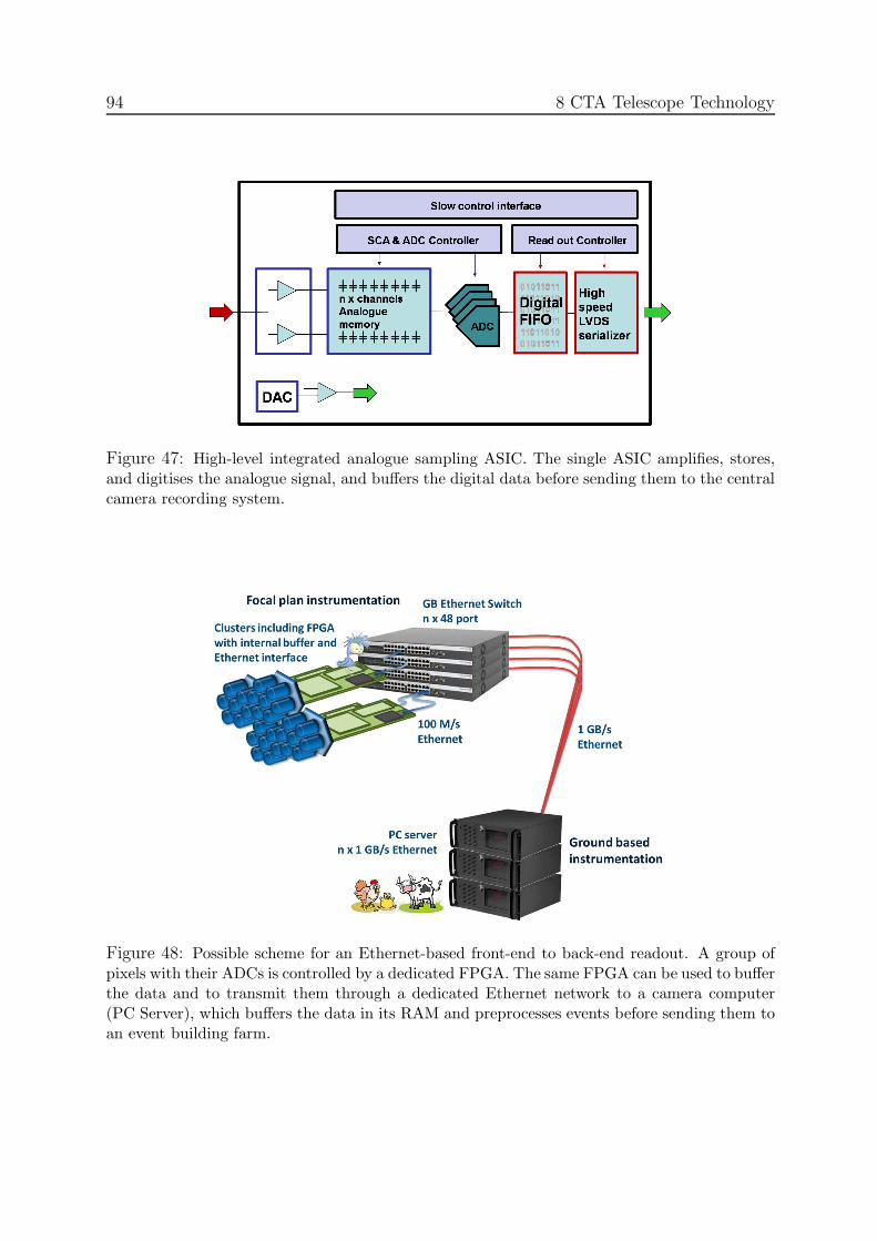
94 8 CTA Telescope Technology
Figure 47: High-level integrated analogue sampling ASIC. The single ASIC amplifies, stores,and digitises the analogue signal, and buffers the digital data before sending them to the centralcamera recording system.
Figure 48: Possible scheme for an Ethernet-based front-end to back-end readout. A group ofpixels with their ADCs is controlled by a dedicated FPGA. The same FPGA can be used to bufferthe data and to transmit them through a dedicated Ethernet network to a camera computer(PC Server), which buffers the data in its RAM and preprocesses events before sending them toan event building farm.

8.3 Photon Detection, Electronics, Triggering and Camera Integration 95
which would imply significantly increasing electronics cost. A specific development effortis also aimed at producing nonlinear input stages providing signal compression.Readout Electronics
Readout of digitised data has so far either relied on custom-built bus systems to collectdata from electronics units covering the camera focal plane (such as the “drawers” of theH.E.S.S. telescopes), or has located the digitisation electronics in commercial VME orPCI crate systems. As a flexible and cost-effective alternative, the use of commercialEthernet systems has recently been explored [77], using normal switches to buffer datasent via a low-level Ethernet protocol (fig. 48). A low-cost front-end gate array emulatesthe Ethernet interface. Data transfer is asynchronous, with buffering in the front-end gatearray, eliminating a source of deadtime. To enable synchronisation, events are tagged atthe front end with an event marker. In tests with 20 sender nodes, transmitting via aswitch to a receiver PC, loss-free transmission of more than 1010 packets with a data rateof more than 80 MByte/s was achieved. Current up-to-date servers can operate with2×4 GBit interfaces and cope with the resulting data flow. It is therefore expected thatloss-free transmission of the front-end data, even of a 2000 pixel camera operating at datarates of 600 MByte/sec, should not be a problem. Nevertheless, various forms of zerosuppression could be implemented in the front end, reducing data rates by up to an orderof magnitude. Since the Ethernet system operates in full-duplex mode, it can also be usedfor the control and parameterisation of the front-end components, such as HV supplies,and to set parameters for triggering, digitisation etc. It would not be necessary to designa separate command bus, as employed in most current cameras.
8.3.3 Triggering
Triggering the Telescopes
Arrays of Cherenkov telescopes typically employ multi-level trigger schemes to keepthe rate of random triggers from the night sky background low. At the first level, signalsfrom individual pixels are discriminated above a threshold. These pixel-level signals areinput to a second level, topological trigger. The topological trigger is used to identifyconcentrations of Cherenkov signals in local regions of the camera, via patten recognitionor a sum of first-level triggers, to form a telescope-level trigger. A third, array-leveltrigger, is formed by combining trigger information from several telescopes.
The trigger chain within a telescope may follow a digital, or analogue path. In H.E.S.S.,Magic and VERITAS, analogue schemes are used, but for CTA several approaches for bothoptions are under investigation. A digital scheme would require the continuous digitisation(with one or more bits) of the signal coming from the PMTs. Components that look forcoincidences from digitised signals with a predefined timing are commercially available. Ina digital scheme, the trigger is very flexible and almost any algorithm can be implemented,even a posteriori. Trigger algorithms and parameter settings for each camera can easilybe adapted for each telescope type, array configuration and for the physics programme(e.g. energy range). Both sector and topological trigger concepts can be implementedin a digital trigger system. The information provided by a digital trigger is essentially“screenshots” of the camera every given time slice. Even if only one or a few bits are used

96 8 CTA Telescope Technology
to encode the trigger information, it may be worthwhile to add this information to thedata stream. In the extreme case of a digital trigger with sufficient resolution, only thedigital stream could be used, as is proposed for the FlashCam development. On the otherhand, the digitisation frequencies available at reasonable cost may yield worse rejectionof random triggers from the night sky background compared to an analogue approach.
The telescope trigger is traditionally formed by looking for a number of pixels abovethreshold, or a number of neighbouring pixels above threshold, within the camera. Thisis typically implemented by dividing the camera up into sectors, which must overlapto provide a uniform trigger efficiency across the camera. By requiring several pixels totrigger at once, random fluctuations due to the night sky background and PMT afterpulsesare greatly reduced. Alternative schemes are also under investigation. These include asum trigger, which can lead to a significant reduction of the trigger threshold [78]. Inthe sum trigger, the analogue or digital sum of all pixels in a cluster is formed and athreshold is set to initiate a trigger. It is necessary to clip pixel signals before summingto prevent large afterpulses triggering a cluster (see fig. 49). All these approaches can beimplemented in both an analogue or a digital path.
Figure 49: Trigger rate (in Hz) against the discriminator threshold (in photo electrons). NSBdominates at low thresholds. Without clipping afterpulses largely dominate the rate (blue), whilethey are effectively eliminated by clipping (red). The black points beyond 25 photo-electronsare due to cosmic showers.
The size of camera sectors and their overlaps have implications for the threshold anddetection efficiency. Given the different goals, they may differ for the LST, MST and SST.Schemes for all telescope sizes are under investigation using Monte Carlo simulations. Theshape and dimensions of the mechanical clusters put limitations on possible camera sectorsand their overlap, but these are only of second order. The default reaction to a trigger

8.3 Photon Detection, Electronics, Triggering and Camera Integration 97
is the read out of the entire camera. Also an autonomous-cluster trigger is under study,however. This allows sections of the camera to form trigger decisions independently andthese are read out autonomously. In the high-energy range, observations at low elevationproduce images that propagate in time through the camera. The propagation time canbe much higher than the usual integration window of the Cherenkov signal acquisition.The autonomous readout would allow the recording of the time slot when the signal is ineach section of the camera, following the propagation of the image through the camera.For low energy showers, the shower image covers a small region of the camera and it canbe useful to read out only a part of the focal plane to save bandwidth on the network andto lower the deadtime of the system.
The earlier a trigger system enters a purely digital level, the more easily and reliablyit can be simulated. Schemes which rely on the addition of very fast analogue or digi-tal signals are potentially more powerful, but could be sensitive to details of the pulseshapes and to the transition-time dispersion between different PMTs, requiring a pre-selection of PMTs with similar transition times or the implementation of matched delaysto compensate for intrinsic differences.
Note that no signal recording scheme rules out the use of a given triggering scheme,but the use of FADCs to record the signal would allow implementation of a digital triggerbased on the already digitised signals, hence reducing the cost and complexity of thesystem.
Triggering the Array
Current array trigger schemes for systems of Cherenkov telescopes [34] provide asyn-chronous trigger decisions, delaying telescope trigger signals by an appropriate amount tocompensate for the time differences when the Cherenkov light reaches the telescopes, andscanning trigger signals for pre-programmed patterns of telescope coincidences. The timeto reach a trigger decision and to propagate it back to the telescopes is about 1 µs or more.While FADC based readout systems can buffer signals for this period, analogue-samplingASICs will usually not provide sufficient memory depth, and require the halting of wave-form sampling after a telescope trigger, while awaiting a third-level telescope coincidencetrigger. The resulting deadtime of a few µs limits telescope (second-level) trigger rates tosome 10 kHz, which does not represent a serious limitation. The latest analogue-samplingASICs allow digitisation of stored signals on time scales of 2 to 3 µs (see tab. 4), compa-rable to the array trigger latency. In this case, a new option for the triggering of the arraybecomes possible: pixel signals are readout and digitised after each telescope trigger, andare stored in digital memory, tagged with an event number. Given that data are bufferedand that buffers can easily be made large, restrictions on array trigger latency are greatlyrelaxed (with GByte memory, about 1 s of data can be buffered) and one can implementa software-based asynchronous trigger. With each local trigger, an absolute timestampis captured for the event with an accuracy of the order of 1 ns and transmitted to thecamera CPU. This computer collects the time stamps and possibly additional trigger in-formation for each event, e.g. pixel trigger patterns, and transmits them every 10-100 msvia standard Ethernet using TCP/IP to a dedicated central trigger computer. The centralcomputer receives all time stamps from all telescopes and uses this information to test for

98 8 CTA Telescope Technology
time coincidences of the events and to derive the telescope system trigger. In addition,the time and trigger information can be used to obtain a first estimate of the core positionand shower direction. Following the central trigger decision, the central trigger CPU sendsthe information to the corresponding telescopes about which of the buffered events are tobe rejected and which fulfil the system trigger condition and should be pre-processed inthe camera CPU and transmitted for further stereoscopic processing. Assuming a localtrigger rate of 10 kHz and that about 100 Byte of trigger information are generated fromeach telescope, the central trigger computer needs to handle up to 100 MByte/sec in a100 telescope system, which can be readily be done with today’s technology. In such atrigger scheme, the central trigger decision is software-based, but the “hard” timing fromthe camera trigger decision is used. It is therefore scalable, fully flexible and all typesof sub-systems can be served in parallel. At the same time it uses the shortest possiblecoincidence gates and provides an optimum suppression of accidental coincidences.
8.3.4 Camera Integration
Signal transmission from the photo-sensors to the recording electronics represents a crit-ical design issue if the electronics is located far from the photo-sensors. Conventionalcables limit bandwidth, are bulky and difficult to route across telescope bearings, and arecostly. MAGIC uses optical signal transmission, circumventing the first two problems,at considerable expense. H.E.S.S. avoids signal transmission altogether by combining16 photo-sensors and their associated electronics in “drawers”, requiring only power andEthernet connection to the camera [79], but limiting flexibility as regards upgrades ofindividual components.
At least for the SST and MST, which are produced in significant quantity and wherecosts of the electronics is a decisive factor, the most effective solution seems to be tocombine photo-sensors and electronics in the camera body. The design should allow easyswapping of the camera for a spare unit, allowing convenient maintenance and repair offaulty cameras at a central facility. However, over the expected lifetime of CTA, upgradesat least of the photo-sensors are likely. The same may be true for the trigger and datarecording systems, where novel networking components may allow transmission of signif-icantly larger amounts of digital data than is currently possible. A viable option couldtherefore be, rather than combining photo-sensors and electronics in a single mechanicalunit, to build a photo-sensor plane with short connections to electronics units, whichin turn feed a trigger system via a flexible interface (fig. 51). For ease of mechanicalassembly, both photo-sensors and electronics will be packaged into multi-channel units.
Dual-mirror solutions, such as the Schwarzschild-Couder telescopes, require muchsmaller cameras and can therefore utilise cheap multi-anode photo-sensors. Fig. 50 showsa possible solution considered for AGIS, using 64-pixel multi-anode PMTs [80].
Mechanical packaging of the entire camera and sealing against the environment is cru-cial for stable performance. In its daytime configuration with closed camera lid, the cam-era body should be reasonably waterproof. Dust penetrating the camera and depositedon connectors and on optical components is a serious issue. To protect the photo-sensorsand the light-collecting funnels and allow for easy cleaning, an optical entrance window

8.3 Photon Detection, Electronics, Triggering and Camera Integration 99
Figure 50: Instrumentation of a 50 cm diameter camera for a dual mirror telescope from 64-pixelmulti-anode PMTs. One pixel is about 6×6 mm2.
made of near-UV transparent material is desirable, even if this induces a modest lightloss due to reflection. While larger-scale integration should reduce power consumptioncompared to current systems, a camera will nevertheless consume kilowatts of power andmust be cooled. Air cooling requires high-quality filtering of the airflow into the camera.Closed-circuit cooling systems, involving internal circulation of a cooling medium andappropriate heat exchangers improve long-term reliability, but add cost and weight.
Figure 51: Concept for packaging of the electronic contained in the camera.

100 8 CTA Telescope Technology
8.4 Calibration and Atmospheric Monitoring
The higher sensitivity of CTA means good gamma-ray statistics for many sources. There-fore, the instrument’s systematic uncertainties may limit the accuracy of the measure-ments. The atmosphere is an integral part of an IACT and so monitoring and correctingfor atmospheric inhomogeneity must be addressed in addition to the detailed calibrationand monitoring of the response and characteristics of the telescopes. Work is ongoing toaddress both issues, as well as their interplay, with the goal of characterising the system-atic uncertainties to an unprecedented level.
Already teams of world-experts have gathered to develop state-of-the-art instrumen-tation for atmospheric monitoring and the associated science for CTA. These teams areactively participating in the corresponding CTA work package (ATAC).
8.4.1 Telescope Calibration
The calibration of the CTA telescopes has two distinct aspects. Firstly, the absolutegain of the system must be determined. Secondly, the pointing accuracy of the telescopemust be measured. The necessity of the precise measurement of the gain of each electronicchannel for CTA requires the development of a single and reliable calibration device whichcan measure the flatfielding coefficients and the ratio between a single photoelectron andthe number of digital counts recorded. This development will add to existing experiencein building calibration devices, for example the H.E.S.S. II flatfielding system as shownin fig. 52. Overall, absolute calibration is achieved by reconstructing the rings generatedby local muons. A special pre-scaled single-telescope trigger could be implemented toenhance the rate at which these are recorded.
In the development of the calibration apparatus, many challenges must be addressed.The first is the difficulty of uniformly illuminating large, wide field-of-view cameras. Thisproblem is twofold: firstly, diffusers must be able to present a uniform signal to the edge ofthe field of view; secondly, the pixels across the field of view must uniformly accept the dif-fused signal on their photo-cathodes. This second aspect can be difficult to achieve whenreflective lightcones on the camera edge have a different acceptance to those in the centreto a close-by, centrally diffused light source. The use of different colour light sources wouldallow the quantification of any differences and/or changes in the quantum efficiency ofpixels. An additional challenge concerns the measurement of the single photo-electron re-sponse. Current telescope systems measure this either in-situ with a low light backgroundlevel, or indirectly using photon statistics [81]. A comparison of these two methods allowsthe study of their associated systematic errors and the choice for the best system for CTA.
The requirements of the telescope pointing measurement are somewhat simpler, butvitally important. Here, a system of two CCD cameras mounted on each telescope isenvisaged. The first measures the position of the night-sky relative to the telescope dishand the second the position of the telescope camera relative to the dish. In combination,the system allows the astronomical pointing of the telescope to be assessed accurately.

8.4 Calibration and Atmospheric Monitoring 101
Figure 52: Layout of the H.E.S.S. II flatfielding and single photoelectron device. For a largearray of telescopes, it is likely that the laser will be replaced by LEDs and that the mechanicalfilter wheel will be replaced by an electronic system.
8.4.2 Atmospheric Monitoring
The calibration of the CTA telescopes is one critical calibration and monitoring task,a second is the monitoring of the atmosphere which forms part of the detector. This iswhere the particle shower is initiated by the incident gamma-ray and the medium throughwhich the Cherenkov photons must travel. The estimation of the energy of an individualgamma-ray is based on the calorimetric energy deposited in the atmosphere, which in turnis measured via Cherenkov photon emission. Therefore, any change in atmospheric qualitycan affect the signal detected. To investigate this effect, a set of benchmark simulations ofa 97-telescope array design were initiated to test the performance of an array of imagingCherenkov telescopes under the presence of varying atmospheric conditions. Simulationswere produced for a clear atmosphere and an atmosphere with a significant layer of low-level dust, as derived from measurements taken with a 355 nm single-scattering Lidardeployed on the Namibian Highlands. These show that, if unaccounted for, the changingatmospheric quality produces a significant shift in the reconstructed gamma-ray spectrum.This can be seen in fig. 53.
Many current Cherenkov telescope arrays have in-situ single-scattering Lidars. Thistype of Lidar possesses a strong and variable systematic error in the derived transmission,up to approximately 50-60% [82]. After discussions with members of the Pierre AugerObservatory (PAO) and other atmospheric scientists, CTA has decided to adopt the

102 8 CTA Telescope Technology
Energy (TeV)110 1
Diff
eren
tial P
hoto
n F
lux
(Arb
itrar
y U
nits
)
910
810
710
Figure 53: Recovering spectral information for non-ideal observing conditions. From a fullsimulation database a randomly sampled spectrum of 105 events with spectral slope of E−2.3 isdrawn. These events are then reconstructed using simulation-based look-up tables which give thereconstructed energy as a function of the camera image brightness and the reconstructed distanceto the shower. For different atmospheric conditions (described in tab. 5), a reconstructedspectrum is derived. The open circles show the reconstructed differential spectrum for case 1,the open squares for case 2 and the closed triangles for case 3. By incorporating Lidar data intothe reconstruction (case 3) a corrected spectrum can be recovered with approximately the samenormalisation and slope as for a clear night sky (case 1).
Case Simulation Derived From Lookup Derived From1 Clear Database Clear Database2 Dusty Database Clear Database3 Dusty Database Dusty Database
Table 5: The combination of look-up tables (as derived from simulations) and simulated spectraproduced to derive the effect of the atmosphere on reconstructed spectra illustrated in fig. 53.
Raman Lidar technique as the tool of choice for accurately probing atmospheric quality.Below and around shower maximum, it is believed that this technique will reduce thesystematic error in derived transmission to approximately 5% [82]. Therefore, RamanLidars are currently under development, which will be installed at the sites of some existingCherenkov telescopes in order to test their efficacy in ground-based gamma-ray analysis.If successful, these atmospheric monitoring systems will allow CTA to significantly reducethe systematic error in energy measurements and derived source fluxes.
8.5 Quality Assurance
Since the design study phase, the CTA project has included a work package named “Qual-ity Assurance and Risk assessment”. The objective of this WP is to implement a uniformapproach to risk analysis in the design, commissioning and operation of the telescopes andof the facility, and for quality assurance of the telescope components and of the assembly

8.5 Quality Assurance 103
procedures.“Risks” are any features that can be a threat to the success of the project. They
can have negative effects on the cost, schedule and technical performance of CTA. Theaim of project risk management is to identify, assess, reduce, accept (where necessary),and control project risks in a systematic and cost-effective manner, taking into accounttechnical and programming constraints.
Quality Assurance ensures a satisfactory level of quality for all steps of the designstudy. This level of quality is guaranteed by correct implementation of the pre-definedquality criteria and the participation of all the project actors.
Including quality assurance and risk assessment from the very start of the design studyphase will have a positive effect on the building schedule and cost of CTA.
The objective of the design study is to develop telescopes which will be produced inseries during the building phase, so the study will be done in partnership with indus-try. Quality assurance and risk assessment will ensure that the project will have goodtraceability and a good control of risks from the outset.
This WP is managed by a coordinator who defines standards and quality methodsfor the project. To ensure the implementation of quality in the project laboratories,“Local Quality Correspondents” (LQCs) will be identified and trained. These people willdedicate part of their time to quality issues, proportional to their laboratory participationin the overall project.
The main tasks of the WP participants are:
• To define the quality insurance organisation (the roles of the participants)
• To ensure that quality control and risk analysis procedures are defined and applieduniformly across the project to ensure high quality and reliability of hardware andsoftware
• To ensure that the risk analysis, including dependability (reliability, availability,maintenance and safety) is defined based on the technical configuration proposed
• To ensure support and expertise to implement the quality system and associatedtools across the project
• To verify the coherence of the procedures and protocols in order to approve themfor subsequent release and use
• To verify the application of the quality procedures across the project
• To identify and reduce technical and management risks
Quality assurance and risk assessment concern the whole project. Thus, the membersof “Quality assurance and risk assessment” will have active links to all work packages, tothe project management and to all laboratories involved in building parts of CTA.

104 9 CTA Site Selection
9 CTA Site Selection
Selection of sites for CTA is obviously crucial for achieving optimum performance andscience output. Criteria for site selection include, among others, geographical conditions,observational and environmental conditions and questions of logistics, accessibility, avail-ability, stability of the host region, and local support:
Geographical conditions: For best sky coverage, the latitude of the sites should bearound 30 north and south, respectively. The sites have to provide a reasonablyflat area of about 1 km2 (north) and at least 10 km2 (south). Optimum overallperformance is obtained for site altitudes between about 1500 and 4000 m. Evenhigher altitudes allow further reduction of the energy threshold [60] at the expense ofperformance at medium and high energies and might be considered for the northernarray. Desirable is also a low component of geomagnetic field parallel to the surface,since such fields deflect air shower particles.
Observational conditions: Obviously, the fraction of clear nights should be high. Forgood sites, this fraction is well above 60%, reaching up to 80% for the very bestsites. Artificial light pollution must be well below the natural level of night skybackground, which excludes sites within some tens of km of major population cen-tres. Atmospheric transparency should be good, implying dry locations with lowamounts of aerosols and dust in the atmosphere.
Environmental conditions: Environment and climate influences both the operationalefficiency and the survival conditions of the instrument. Wind speeds above 10 m/smay impact observations; peak wind speeds, which may range from below 100 km/hto beyond 200 km/h depending on the site, have a major impact on telescope struc-ture and cost. Sand storms and hail represent a major danger for unprotected mirrorsurfaces. Snow and ice prevent observations and will influence instrument costs, e.g.by making heating systems necessary and requiring increased structural stability.Seismic activity will similarly increase requirements on telescope structures andbuildings.
Infrastructure and logistics: A well-developed infrastructure, e.g. as a result of al-ready existing observatories, is an advantage. Connection to the power grid andhigh speed internet access are mandatory. There should be good access to the site,i.e. nearby airports for air travel to/from Europe and elsewhere, and local accessroads. A major population centre with technical and commercial infrastructurewithin convenient travel distance is desirable.
Other criteria: These include availability of the site for construction, guarantees forlong-term operation and access, political stability of the host region, safety of per-sonnel, both during travel and stay, and availability of local administrative, techni-cal and funding support as well as possibilities for scientific cooperation with localgroups.

105
For both the observational and the environmental conditions, a long-term (multi-year)data record is required to allow dependable decisions o be made. While archival remote-sensing data can provide some information, well-explored sites with existing installationsand good records are favoured. It is unlikely that any site is optimal in all respects, sothe different criteria will have to be balanced against each other. Reliable and efficientoperation of the observatory should be a key criterion.
Site evaluation includes a number of different approaches, at different stages of progressfor a candidate site:
• Use of remote-sensing archival data and local archival data to evaluate observingconditions and environmental conditions.
• Site visits and information gathering by local collaborating groups on logistics as-pects.
• Dedicated CTA measurements; since long-term measurements are excluded, thisapproach is useful only for those quantities where short campaigns can providemeaningful results, such as the determination of natural and artificial night-skybrightness.
Figure 54: Green areas indicate sites above 1500 m a.s.l., which offer sufficiently flat areas,minimal artificial background light and an average cloud cover of <40%, selected on the basisof topological and satellite data.
A first preselection can look for sufficiently large and flat areas above 1500 m a.s.l.(based on a topological model of the Earth [83]), with the requirement that the artificialbackground light is minimal (as determined from satellite images [84]), and that averagecloud coverage is less than 40% (as provided by the International Satellite Cloud Clima-tology Project, ISCCP, based on the analysis of satellite data [85]). The resulting map(fig. 54) shows very few locations matching these basic criteria, among them the well-known sites in Chile and Namibia. However, while the ISCCP data has the advantage ofcovering the whole planet, the resolution is relatively coarse and sites with very local con-ditions (such as mountain tops) may deviate significantly from the “pixel” average. Also,daytime and nighttime cloud cover will usually be different. Only the latter is relevant

106 9 CTA Site Selection
for Cherenkov astronomy. For identification of potential observatory sites, special algo-rithms and high-resolution data have been provided by Erasmus [86] for the identificationof potential observatory sites, but only for selected areas, such as the Chilean sites, theIndian site at Hanle or the Yanbajing site in Tibet. Similar searches are conducted usingMODIS and ISCCP maps as well as the recently released ESO application FriOwl thatprovides access to an extensive database of information from the last 40 years [87].
Based on these preliminary evaluations, potentially interesting sites have been selectedat which detailed studies will be conducted in the coming months.
Northern site candidates are:
Canary Islands La Palma and Tenerife: These are well-known and well-explored ob-servatory sites at about 26 N, about 2400 m a.s.l., with the Observatorio del Roquede los Muchachos on La Palma and the Observatorio del Teide on Tenerife.
Hanle in India, in the Western Himalayas: This high-altitude site (33 N, 4500 ma.s.l.) hosts a small observatory and an array of Cherenkov instruments which isdeployed by Indian groups.
San Pedro Martir, Baja California: Well-established astronomical site that hosts al-ready two observatories run by UNAM (Universidad Autonoma de Mexico). It issituated at about 31 N, at 2800 m a.s.l..
Southern site candidates are:
Khomas Highland of Namibia: This is a well-known astronomical site, at 1800 ma.s.l. and 23 S, and is the home of the H.E.S.S. instrument. The region offers arange of suitable, large and flat areas.
Chilean sites: Chile is home to some of the World’s premier optical observatories. How-ever, availability of sufficiently large cites near these locations is limited. A possiblesite is north of La Silla at 29 S and 2400 m a.s.l. Another potential site is nearCerro Paranal, with even better observing conditions, but no sufficiently flat areain this region has been identified so far.
El Leoncito Reserve in Argentina: This site is at 32 S and 2600 m a.s.l. and hoststhe El Leoncito Astronomical Observatory.
Puna Highland in Argentina: The region offers some large sites at 3700 m a.s.l.. withsky quality equivalent to the best Chilean ones. These sites have good access to arailway line.
The final decision among otherwise identical sites may rely on considerations such as fi-nancial or in-kind contributions by the host regions. It is likely that an inter-governmentalagreement will be required to assure long-term availability of the site, as well as guaran-teed access and free transfer of data. At the same level, issues such as import taxes, valueadded tax and fees etc. should be addressed. Such agreements exist, for H.E.S.S., Augerand other observatories operated by international collaborations.

107
10 Outlook
The Cherenkov Telescope Array was conceived back in 2005, and was then promoted bymembers of the HESS and MAGIC collaborations. It was soon apparent that a gamma-ray observatory could be designed with existing technologies that was much more powerfulthan any of the existing facilities. An improvement of a factor of 10 in sensitivity arounda TeV and an extension of the energy range from a few tens of GeV to >100 TeV, wellbeyond the currently accessible range, was achievable with an array of a large number (≈100) of differently sized telescopes.
With the results from current Cherenkov telescopes pouring in, it became obviousthat with such an instrument a vast number of sources of very different types could bediscovered and studied with unprecedented precision. Answers to long-standing questionsin a number of science areas seemed possible. The extent and the diversity of the sciencecase was, and is, stunning (see sec. 2). CTA would truly be the first large open observatoryfor astronomy of the extreme universe beyond the GeV range.
Not surprisingly, many scientists were attracted to CTA and its science grew rapidly,as did the number of supporters who now form a large international collaboration whichis investigating how best to realise the project. CTA has received consistently excellentreviews and high rankings in Science Roadmaps in Europe and across the world. CTA is anacknowledged ESFRI project, features high on the roadmaps of future projects of ApPEC,ASPERA and ASTRONET and has been well received by national funding agencies. Thepotential of CTA is well recognised outside Europe, with the USA, Japan, India, Braziland Argentina, and other countries contributing significantly. The US Decadal Surveyendorsed a strong US participation in CTA as one of the four most important groundbased initiatives in the next ten years.
Since 2006, and specifically in a 4-year design study, it has been shown that CTA,with observatories in the northern and southern hemisphere, can be built to achieve itsgoal performance, at an investment cost in the range of 150 Me, which is a modest pricefor an installation of such scientific potential.
CTA has recently received substantial funding from the European Community, forpreparing for construction and operation, and from national funding agencies, for devel-opment and prototyping. There is much excitement amongst all participants, and thewider science community, about the prospects that CTA will soon from design to reality.
In this report, an account of the main design work performed so far is presented, whichconstitutes a solid basis for the prototyping and construction phases that lie ahead. ThePreparatory Phase (3 years) and the subsequent construction phase (2013-2018) will posemany challenges. But CTA is a well-organised international collaboration of 25 countriesand >600 scientists with extensive expertise in all relevant areas. Its members are eagerand ready to tackle the problems that lie ahead.
This effort is well worth it, as CTA will provide a huge science return in astrophysics,particle physics, cosmology and fundamental physics, and lead to a bright future forground-based gamma ray astronomy.

108 REFERENCES
References
[1] Proc. 2nd Int. Meeting on High Energy Gamma-Ray Astronomy Heidelberg (2004)AIP Conference Proceedings Volume 745 (2004)Eds: F.A. Aharonian, H.J. Volk, D. Horns
[2] Proc. 4th Int. Meeting on High Energy Gamma-Ray Astronomy Heidelberg (2008)AIP Conference Proceedings Volume 1085 (2008)Eds: F.A. Aharonian, W. Hofmann, F. Rieger
[3] J.A. Hinton, W. Hofmann, Ann. Rev. of Astronomy and Astrophysics 47 (2009) 523
[4] F.A. Aharonian et al., Rep. on Prog. in Physics 71 (2008) 096901
[5] J. Buckley et al., AGIS White Paper [arXiv:0810.0444v1]
[6] 2nd Fermi Symposium (2009) Washington, Capitol Hill, eConf Proceedings C091122:http://www.slac.stanford.edu/econf/C0911022/
[7] 31st ICRC, 2009, Lodz, Polandhttp://icrc2009.uni.lodz.pl/
[8] B.M. Gaensler and P.O. Slane, Ann. Rev. of Astronomy and Astrophysics 44 (2006) 17
[9] O.C. de Jager, A. Djannati-Atai, Springer Lecture Notes on “Neutron Stars and Pulsars:40 years after their discovery”, eds. W. Becker (2008) [arXiv:0803.0116v1]
[10] A. Levinson, Int. J. Mod. Phys. A21 (2006) 6015
[11] Proc. “High Energy Phenomena in Massive Stars”, University of Jaen, Ed.: J Marti (2010)ASP Conference Series, Vol. 422. ISBN: 978-1-58381-724-7
[12] Proc. “1st Session of the Sant Cugat Forum of Astrophysics: ICREA International Work-shop on The High-Energy Emission from Pulsars and their Systems”, N. Rea & D.F.Torres (Editors), 2010, Springer, ISSN:1570-6591.
[13] Proc. “High-energy phenomena in relativistic outflows II”, G.E. Romero, F.A. Aharonianand J.M. Paredes Eds., Buenos Aires, Argentina (2009)International Journal of Modern Physics D 19 (2010)and http://hepro2.iar-conicet.gov.ar/talks.html
[14] “Particle dark matter” edited by G. Bertone, Cambridge University Press (ISBN-13:9780521763684)
[15] M. Martinez, J. Phys. Conf. Ser. 171 (2009) 012013
[16] R. Hanbury Brown, The Intensity Interferometer (1974) Taylor & Francis LTD, London
[17] D.B. Kieda, S.P. Swordy, S.P. Wakely, Astropart. Phys. 15 (2001) 287
[18] J. Hinton, New Journal of Physics 11 (2009) 055005

REFERENCES 109
[19] J. Hinton et al., H.E.S.S. Collaboration “Background modelling in ground-based Cheren-kov astronomy” Proc. “Towards a Network of Atmospheric Cherenkov Detectors VII”,Palaiseau, France, 2005, p. 183-190
[20] J. Albert et al. (MAGIC Collaboration), “Very high energy gamma-ray observations dur-ing moonlight and twilight with the MAGIC telescope” [astro-ph/0702475]
[21] W. Hofmann, Performance Limits for Cherenkov Instruments, Proc. “Towards a Networkof Atmospheric Cherenkov Detectors VII”, Palaiseau, France, 2005, [astro-ph/0603076]
[22] G. Maier, J. Knapp, Astrop. Phys. 28 (2007) 72 [astro-ph/0704.3567]
[23] C. Amsler et al. (Particle Data Group)Phys. Lett. B 667 (2008) 1 (section 27.5. Electromagnetic cascades, p 276)
[24] F.A. Aharonian et al. (H.E.S.S. Collaboration), Phys. Rev. D 75 (2007) 042004
[25] V. Sahakian, F. Aharonian, A. Akhperjanian, Astropart. Phys. 25 (2006) 233
[26] E. Aliu et al., Astrop. Phys. 30 (2009) 293
[27] A. Schliesser, R. Mirzoyan, Astropart. Phys. 24 (2005) 382
[28] V.V. Vassiliev, S.J. Fegan, P.F. Brousseau, Astropart. Phys. 28 (2007) 10,[astro-ph/0612718]
[29] F. Aharonian et al., J. Phys. G 21 (1995) 985
[30] M. de Naurois, L. Rolland, Astropart. Phys. 32 (2009) 231
[31] J. Albert et al., Nucl. Instr. Meth. A 594 (2008) 407
[32] R. Mirzoyan et al., Astropart. Phys. 25 (2006) 342
[33] J. Albert et al. (MAGIC Collaboration) Nucl. Instrum. Meth. A594 (2008) 407-419,[astro-ph/0612385]
[34] S. Funk et al. Astropart. Phys. 22 (2004) 285 [astro-ph0408375]
[35] ASPERA Roadmaphttp://www.aspera-eu.org/images/stories/roadmap/aspera roadmap.pdf
[36] AGIS homepage: http://www.agis-observatory.org/
[37] HAWC homepage: http://hawc.umd.edu/
[38] CTA Computing Grid:http://lappwiki01.in2p3.fr/CTA-FR/doku.php?id=cta-computing-grid-public
[39] D. Heck et al., CORSIKA: A Monte Carlo code to simulate extensive air showers, TechnicalReport FZKA 6019, Forschungszentrum Karlsruhe, 1998http://www-ik.fzk.de/corsika/

110 REFERENCES
[40] M.P. Kertzman, G.H. Sembroski, Nucl. Instr. Meth. A343 (1994) 629
[41] K. Bernlohr, Astropart. Phys. 30 (2008) 149
[42] J. Guy, These de doctorat, Universite Paris VI (2003)
[43] P. Majumdar et al. Monte Carlo simulations for the MAGIC telescopeProc. 29th ICRC, Pune, 5 (2005) 203
[44] M. Hillas, Proc. 19th ICRC, La Jolla 3 (1985) 445
[45] R.K. Bock, A. Chilingarian, M. Gaug, et al. Nucl. Instr. Meth. A516 (2004) 511
[46] TMVA: http://tmva.sourceforge.net
[47] S. Ohm, C. van Eldik, K. Egberts, Astropart. Phys. 31 (2009) 383
[48] A. Fiasson, F. Dubois, J. Masbou, G. Lamanna, S. Rosier-LeesAstropart. Phys. 34 (2010) 25
[49] M. Lemoine-Goumard, B. Degrange, and M. TluczykontAstropart. Phys. 25 (2006) 195
[50] R. Cornils et al., Astropart. Phys. 20 (2003) 129
[51] F.A. Aharonian et al., Astrophys. Journal 664 (2007) L71
[52] G. Battistoni, S. Muraro, P.R. Sala, F. Cerutti, A. Ferrari, S. Roesler, A. Fasso, J. Ranft,Proc. “Hadronic Shower Simulation Workshop 2006”, Fermilab 2006, M. Albrow, R. Rajaeds., AIP Conf. Proc. 896 (2007) 31A. Fasso, A. Ferrari, J. Ranft, and P.R. SalaCERN-2005-10 (2005), INFN/TC 05/11, SLAC-R-773
[53] S.A. Bass et al., Prog. Part. Nucl. Phys., 41 (1998) 225M. Bleicher et al., J. Phys. G: Nucl. Part. Phys. 25 (1999) 1859
[54] N.N. Kalmykov et al., Nucl. Phys. B (Proc. Suppl.) 52B (1997) 17
[55] S.S. Ostapchenko, Nucl. Phys. B (Proc. Suppl.) 151 (2006) 143 and 147
[56] S.S. Ostapchenko, Phys. Rev. D 74 (2006) 014026
[57] R. Engel et al., Proc. 26th ICRC (Salt Lake City), 1 (1999) 415
[58] F.A. Aharonian et al., Phys. Rev. Letters 101 (2008) 261104
[59] K. Bernlohr et al. Proc. 30th ICRC, Merida 3 (2007) 1469
[60] F.A. Aharonian, A.K. Konopelko, H.J. Voelk, H. QuintanaAstropart. Phys. 15 (2001) 335
[61] A. Plyasheshnikov, private communication.

REFERENCES 111
[62] A. Konopelko, J. Phys. G: Nucl. Part. Phys. 30 (2004) 1835
[63] S. Funk, J.A. Hinton, Proc. “4th Heidelberg Int. Symposium on High Energy Gamma-RayAstronomy 2008”
[64] G. Maier et al. (AGIS Collaboration), Proc. 32st ICRC, Lodz, Poland (2009)[arXiv:0907.5118v1]
[65] K. Schwarzschild, Untersuchungen zur geometrischen Optik II: Theorie der Spiegeltele-scope (1905) Abhandlungen der Gesellschaft der Wissenschaften in Gottingen, Bd 4, 2(1905) 1
[66] G.W. Ritchey, Comptes Rendus 185 (1927) 1024
[67] J. M. Davies, E. .S. Cotton, J. Solar Energy Sci. Eng. 1 (1957) 16
[68] K. Bernlohr et al., Astropart. Phys. 20 (2003) 111
[69] A. Biland et al. (MAGIC Collaboration) Proc. 30th ICRC Merida 3 (2007) 1353
[70] M. Doro et al., Nucl. Instr. and Meth. A595 (2008) 200
[71] G. Pareschi et al., Proc. SPIE 7018 (2008) 70180W
[72] J. Holder et al., Astropart. Phys. 25 (2006) 391
[73] P. Cogan for the VERITAS Collaboration, Analysis of Flash ADC Data With VERITAS[arXiv:0709.4208v2]
[74] M. Punch et al., AIP Conf. Proc. 515 (2000) 373
[75] E. Delagnes, et al., Nucl. Instr. Meth. A 567 (2006) 21
[76] D. Tescaro et al., “The readout system of the MAGIC-II Cherenkov telescope”arXiv:0907.0466
[77] G. Hermann et al. Proc. “4th Heidelberg Int. Symposium on High Energy Gamma-RayAstronomy 2008”, [arXiv:0812.0762]
[78] E. Aliu et al. (MAGIC Collaboration), Science 322 (2008) 1221
[79] F. Aharonian et al. (H.E.S.S. Collaboration), Astrop. Phys. 22 (2004) 109
[80] S. Digel et al. for the AGIS Collaboration, Talk at 2009 SLAC Users Organisation Meetinghttp://www-group.slac.stanford.edu/sluo/2009AnnualMeeting/Talks/Tajima.pdf
[81] D. Hanna et al., Nucl. Instr. Meth. A612 (2009) 278
[82] A. Papayannis & E. Fokitis, Pierre Auger Observatory, Internal Note (1998) GAP 1998-018
[83] U.S. Geological Survey, GTOPO30,http://eros.usgs.gov/products/elevation/gtopo30.html

112 REFERENCES
[84] P. Cinzano, F. Falchi, C.D. Elvidge, MNRAS 328 (2001) 689
[85] International Satellite Cloud Climatology Projecthttp://isccp.giss.nasa.gov/products/dataview.html
[86] D.A. Erasmus, “An analysis of cloud cover and water vapor for the ALMA project” (2002),(www.eso.org/gen-fac/pubs/astclim/espas/radioseeing/)“An analysis and comparison of satellite-observed cloud cover and water vapor at Hanle,India and Yanbajing, Tibet” (2004)http://www.saao.ac.za/∼erasmus/Projects/MPIHimalaya/MPIHimalaya overview.html
[87] FriOWL site selection tool: http://archive.eso.org/friowl-45/


![In conjunction with Venus [planetary radar astronomy]](https://static.fdokumen.com/doc/165x107/631a4f09bb40f9952b01f2bc/in-conjunction-with-venus-planetary-radar-astronomy.jpg)