Amateur Radio Astronomy
31
Amateur Radio Astronomy by Dr. Alex Vrenios [email protected] www.AstroLeague.org “Five Projects” www.Radio-Astronomy.org West Valley Astronomy Club Surprise, AZ October 2, 2019
-
Upload
khangminh22 -
Category
Documents
-
view
0 -
download
0
Transcript of Amateur Radio Astronomy
Amateur Radio Astronomy
by
Dr. Alex [email protected]
www.AstroLeague.org
“Five Projects”
www.Radio-Astronomy.org
West Valley Astronomy ClubSurprise, AZ
October 2, 2019

Early Pioneers in Radio Astronomy:1932 Karl Jansky, investigating radio interference from thunder storms,
discovered a radio source “outside our solar system,” which later proved to be the center of our galaxy, the Milky Way.
1937 Grote Reber, a ham radio operator (W9GFZ), heard about Jansky’s discovery but the Great Depression left him out of work. He built a 30’ dish in his own backyard and mapped the radio sky, making him the world’s first radio astronomer!
1944 H. C. van de Hulst, a grad student working for Jan Oort, reasoned that these radio signals must be coming from hydrogen atoms in space, each of which could emit radio waves. A slight instability in the atom caused the release of a quantum of energy every 11 million years. But there are so many of these atoms in space that a “peep” from each one amounted to a continuous roar.
1963 Arno Penzias and Robert Wilson discovered an unexplainable Cosmic Microwave Background Radiation coming from every direction. If the Universe began with a Big Bang, they reasoned, it would have left such an artifact. They won a Nobel Prize in 1978.

“Five Projects”– Presentation Overview:
• #1 Observing the Sun’s Energy
• #2 Detecting a SID: Sudden Ionospheric Disturbance
• #3 Listening to Jupiter’s Radio Storms
• #4 Detecting Meteors
• #5 Detecting Galactic Radio Sources
• The RAOP Award Certificates and Pins
• Radio Frequency Imaging
• Further References
• Recap – Q&A
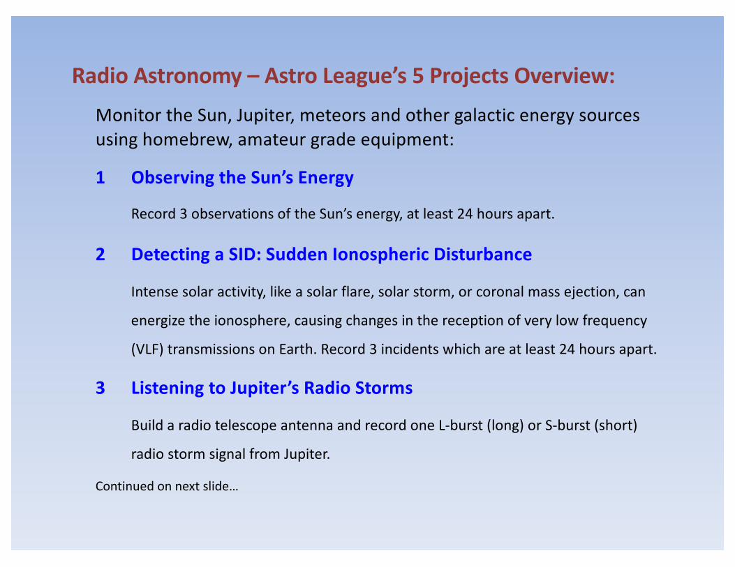
Radio Astronomy – Astro League’s 5 Projects Overview:Monitor the Sun, Jupiter, meteors and other galactic energy sources using homebrew, amateur grade equipment:
1 Observing the Sun’s Energy
Record 3 observations of the Sun’s energy, at least 24 hours apart.
2 Detecting a SID: Sudden Ionospheric Disturbance
Intense solar activity, like a solar flare, solar storm, or coronal mass ejection, can
energize the ionosphere, causing changes in the reception of very low frequency
(VLF) transmissions on Earth. Record 3 incidents which are at least 24 hours apart.
3 Listening to Jupiter’s Radio Storms
Build a radio telescope antenna and record one L-burst (long) or S-burst (short)
radio storm signal from Jupiter.
Continued on next slide…

Radio Astronomy – Astro League’s 5 Projects: (continued)
4 Detecting Meteors
Meteors ionize their path through the atmosphere which can reflect signals from
distant terrestrial radio stations. A high quality FM receiver can be used to detect
them. (More on this later.) Include a recording of at least ten such events.
5 Detecting Galactic Radio Sources
Detect hydrogen in the galactic plane using a dish, multi-element Yagi, or “horn”
antenna, etc. Include ten observations of at least three different objects. An object
may be observed more than once, but observations must be made at least 24 hours
apart. Note that hydrogen gives off radio frequency bursts at 1420 MHz (21 cm).
Submit results from one of these projects for Bronze level, two for
Silver, and four for Gold. Results must include those from project #5.
Reference: The Astronomical League website at www.astroleague.org/programs/radio-astronomy-observing-program

Project #1 – Observing the Sun’s Energy:
1. One option is to use a typical home or
RV satellite TV dish antenna system.
2. Attach a signal strength meter – a low cost one will do.
(Photos of your interaction with the equipment are required.)
3. Slowly pulse the dish across the Sun’s face.
Record and plot the signal strength readings.
Alternatively, record the signal intensities as
the Sun “drifts” across the face of your dish.
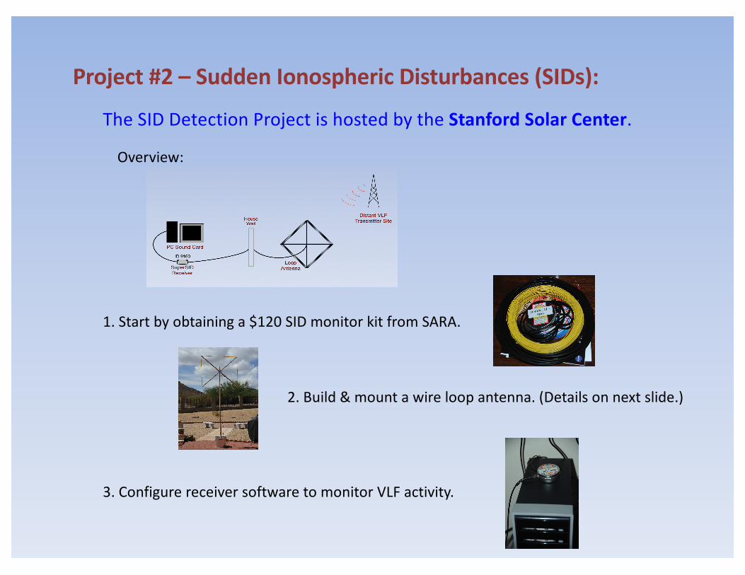
Project #2 – Sudden Ionospheric Disturbances (SIDs):
The SID Detection Project is hosted by the Stanford Solar Center.
Overview:
1. Start by obtaining a $120 SID monitor kit from SARA.
2. Build & mount a wire loop antenna. (Details on next slide.)
3. Configure receiver software to monitor VLF activity.

Wire for loop is included in a kit from SARA. Wooden brace was treated with four coats of “spar” polyurethane before assembly. An electrical box cover strengthens the brace and a U-bolt connects it to the mast.
Project #2 – SID Antenna Assembly Details:
Loop antenna partsready for assembly.
The loop antenna can be indoors, but it is more effective outdoors. It doesn’t have to be high up.
The wooden brace is held together by an electrical box cap and a U-bolt will hold it to the pole mount. The wire is carefully wound around the end caps of the wooden brace.
Finishing nails used to hold loop of wirein place on brace.
Cross member support. U-bolt for pole mount.

Project #2 – SID Expected Results:
Credit: Lionel Loudet, http://sidstation.loudet.org
Signal plot on a quiet day:
Signal plot of a day with two SID events:

Project #3 – Detecting Jupiter’s Radio Storms:Jupiter detection system overview:
Jupiter detection system components:

Project #3 – Jupiter Receive Antenna Assembly Details:This antenna is from a design in the December 1989 issue of Sky & Tel, page 628.
But, most will tell you that it’s a terrible design. (Some will say that it can’t work!)
Loop Antenna Assembly Instructions Loop Antenna Parts
Loop Antenna Back Brace Loop Antenna Ready for Mounting Jupiter Loop Antenna Mounted

Project #3 – Predicting Jupiter’s Radio Storms:
Jupiter’s three sectors and its moon, Io, influence reception of radio storms:
Scientists have detected three sectors, or longitudinal regions relative to the
CML (Central Meridian Line), labeled A, B and C.
When one of them is pointing at the Earth, the
likelihood of hearing storm increases, with A
being the most likely, etc. If Jupiter’s moon, Io,
is also angled at about ninety degrees to Earth,
the likelihood of hearing a storm is further increased.
So, all we have to do is point our antenna and
tune around the HF bands, somewhere between
18 and 22 MHz, and wait for an alignment, right?
Well, no. Fortunately, there is a Jupiter radio storm prediction software
package that is reasonably priced...
Credit: http://commons.wikimedia.org
Io
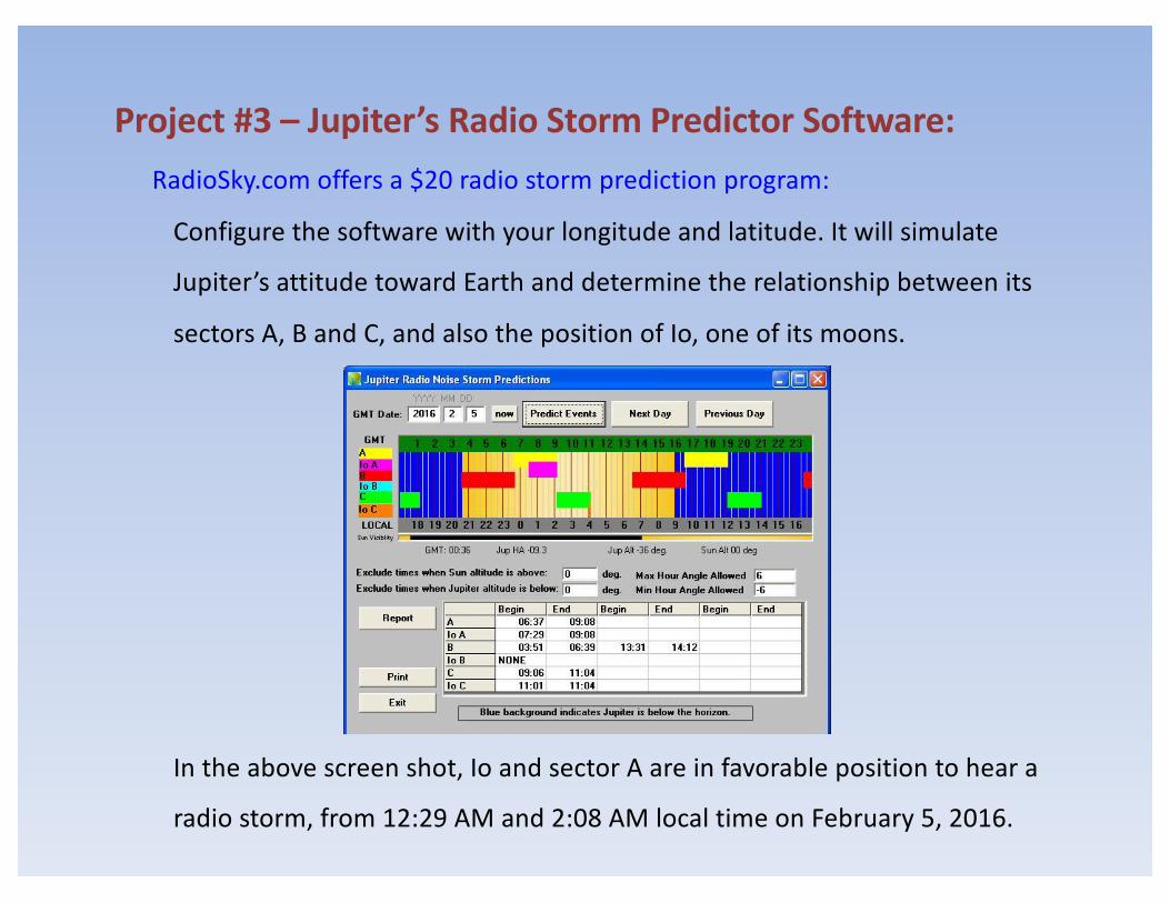
Project #3 – Jupiter’s Radio Storm Predictor Software:RadioSky.com offers a $20 radio storm prediction program:
Configure the software with your longitude and latitude. It will simulate
Jupiter’s attitude toward Earth and determine the relationship between its
sectors A, B and C, and also the position of Io, one of its moons.
In the above screen shot, Io and sector A are in favorable position to hear a
radio storm, from 12:29 AM and 2:08 AM local time on February 5, 2016.

Project #3 – Detecting Jupiter’s Radio Storm Signals:
S-Burst
February 5, 20161:43am on 19.515 MHz
Patience, perseverance, and a little financial assistance are soon rewarded:
Long (L-Burst) signals sound like waves crashing against the shore. Short (S-Burst)
signals either sound like a wood pecker, or like a plastic bag flapping in the wind.
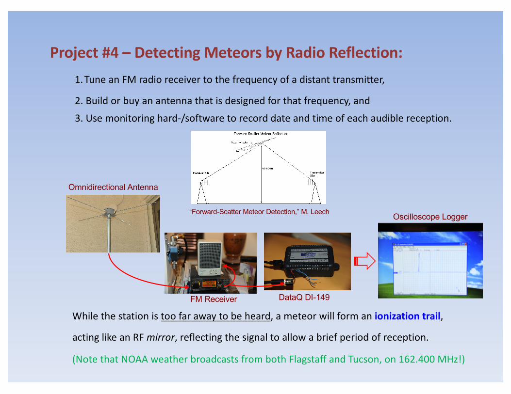
Project #4 – Detecting Meteors by Radio Reflection:1.Tune an FM radio receiver to the frequency of a distant transmitter,
2. Build or buy an antenna that is designed for that frequency, and
3. Use monitoring hard-/software to record date and time of each audible reception.
While the station is too far away to be heard, a meteor will form an ionization trail,
acting like an RF mirror, reflecting the signal to allow a brief period of reception.
(Note that NOAA weather broadcasts from both Flagstaff and Tucson, on 162.400 MHz!)
“Forward-Scatter Meteor Detection,” M. Leech
FM Receiver DataQ DI-149
Oscilloscope Logger
Omnidirectional Antenna
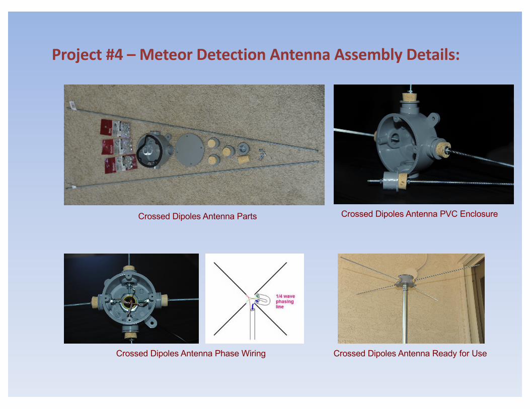
Project #4 – Meteor Detection Antenna Assembly Details:
Crossed Dipoles Antenna Phase Wiring
Crossed Dipoles Antenna Parts Crossed Dipoles Antenna PVC Enclosure
Crossed Dipoles Antenna Ready for Use
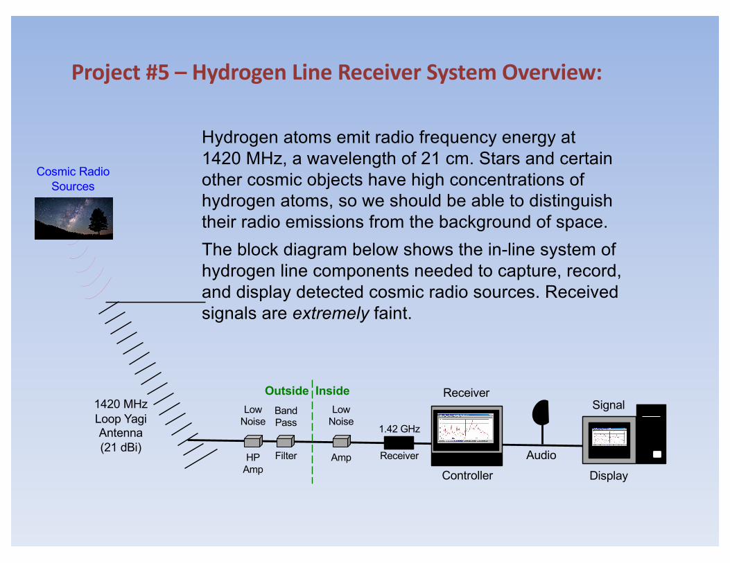
Hydrogen atoms emit radio frequency energy at 1420 MHz, a wavelength of 21 cm. Stars and certain other cosmic objects have high concentrations of hydrogen atoms, so we should be able to distinguish their radio emissions from the background of space.The block diagram below shows the in-line system of hydrogen line components needed to capture, record, and display detected cosmic radio sources. Received signals are extremely faint.
Project #5 – Hydrogen Line Receiver System Overview:
1420 MHzLoop YagiAntenna(21 dBi)
1.42 GHz
Receiver
ReceiverBandPass
Filter
LowNoise
HPAmp
SignalLowNoise
Amp
DisplayControllerAudio
Outside Inside
Cosmic RadioSources

Project #5 – Hydrogen Line Receiver System Components:I built a frame to hold the commercial 1420 MHz Yagi antenna. A Low Noise
Amplifier (LNA) boosts the antenna’s signal, and a 1420 MHz band pass filter
suppresses unwanted noise, above and below the desired frequency. An SDR
(software defined radio receiver, an AirSpy R2), detects the 1420 MHz signal
frequency as a hiss, SDR# software displays it, and Radio Sky Pipe records its
strength as each Cosmic Radio Source drifts across the antenna’s viewpoint.
1420 MHz LNA
Windows 7
1420 MHz
Band Pass Filter 1420 MHz HighPerformance LNA
1420 MHzYagi 21 dBi
Antenna
Speaker
Windows XP
Radio Sky PipeSDRsharp
Inside OutsideAirSpy SDR
Receiver (R2)

Starry Night 7 software showsThe altitude of the radio sourceand when it will be true south
Project #5 – Hydrogen Line Antenna System Details (1 of 2):The antenna’s feed point is best kept away from metal. The thick-walled
PVC pipe, with an inner pipe in the top section, will support the antenna.
H-Line antennasupport components
The cross member provides a pivotpoint, so I can adjust the elevation
Original designbuilt with metal fence post rails(slightly overkill)
Struts rebuilt withPVC (Charlotte)thick-wall tubingsag a little but itsupports it okay
Smaller tube inside larger
Adjusting antenna elevation

Project #5 – H-Line Antenna System Details (2 of 2):My H-Line antenna is a 1.42 GHz loop Yagi with a 21 dBi gain. This antenna is
commercially produced by Direct Systems & Engineering. The two Low Noise
Amplifiers are from Down East Microwave and the Band Pass Filter is from
Radio Astronomy Supply. All coax is 50 ohm Times Microwave LMR-400.
Antenna pointsapproximately
true south
Antenna feed pointdetail showing theLNA and BP Filter

Project #5 – Hydrogen Line Drift Scan Method:
In the drift scan method, you point your antenna to where the radio
object of interest will be. As the object drifts by, the received signal
strength increases to a maximum, then decreases back to the baseline.
Energy from the Sun can be used to establish the half-power beam width
of your radio astronomy antenna system:
Note: The detected signal is
actually thermal energy from
the Sun, not radio waves from
its hydrogen content.
Half-Power Beam Width (HPBW)12:02pm to 1:06pm = 1 Hour+ -> 16°

Project #5 – Hydrogen Line Drift Scan Results:
Drift scan sample results – ten such detections are required by the AL:
Cygnus A
Sep 25, 2016 from 7:18pm to 8:35pm MSTDetection begins at 8:06pm MST = 0306Z.
Detection
Taurus A (M1)
Sep 24, 2016 from 5:20am to 6:52amDetection begins at 6:15am = 1315Z.
Detection
The Radio Astronomy Observing Program Awards:
1 - Detecting Solar Radiation
Bronze
2 - Sudden Ionospheric Disturbances (SIDs)
Blah...
3 – Jovian Radio Storms
Silver
4 - Meteor Scatter Communications
5 - Galactic H-Line Radiation
Gold!
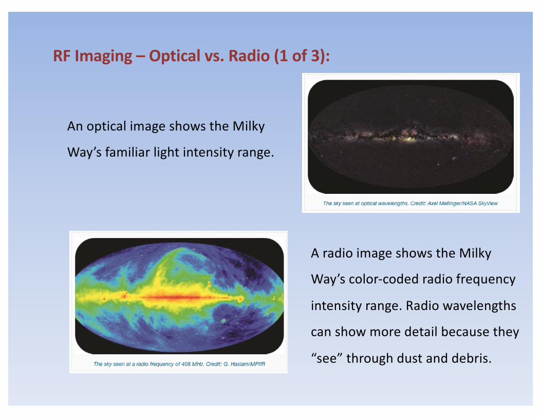
RF Imaging – Optical vs. Radio (1 of 3):
An optical image shows the Milky
Way’s familiar light intensity range.
A radio image shows the Milky
Way’s color-coded radio frequency
intensity range. Radio wavelengths
can show more detail because they
“see” through dust and debris.

RF Imaging – Optical vs. Radio (2 of 3):
An optical image shows Centaurus A
at optical wavelengths.
A radio image shows Centaurus A’s
radio frequency jets – much more
information than the optical image.
“I’m a Radio Astronomer,” Anna Ho, MIT

“I’m a Radio Astronomer,” Anna Ho, MIT
RF Imaging – Optical vs. Radio (3 of 3):
This optical image shows the M81
and M82 Group, in Ursa Major, at
optical wavelengths.
The radio image shows the M81 & M82
at hydrogen wavelengths. It correlates
to the optical image, but it also shows
how these objects are interacting.

A composite image from the drift scan data at left.
RF Signal
Intensity
Scale
Time
Drift Scan #1
Drift Scan #2
Drift Scan #3
Drift Scan #4
Encoded RF Signal IntensitiesSampled at 5 Points in Time.
A higher gain antenna means smaller
pixels, which translates into greater
resolution, or finer detail in an image.
RF Imaging – How it might be done from drift scan data:
Five intensity samples effectivelydigitizes the signal data.
Each night the antenna is dropped down a bit.
We’re gonna need a bigger dish…
Radio Frequency Image

Size Matters – Some Very Big Radio Telescopes:
Credit: panoramio.com
Green Bank’s 100 meter diameter radio telescope,
the largest fully steerable, single aperture antenna
is located in Green Bank, West Virginia, USA.
Aricibo, Puerto Rico, is 1000 feet in
diameter, built in a depression left
by a karst sinkhole. Construction
began in 1963. Credit: Space.com
The Karl Jansky Very Large Array
is located west of Socorro, NM,
comprising twenty-seven, 25m
dishes in a “Y” shape. (1973-80.)Credit: NRAO

Size Matters – More Very Big Radio Telescopes:China’s Five-hundred-meter Aperture
Spherical Telescope (FAST), in Guizhou
Province, is about twice as sensitive as
the next-biggest single-dish radio telescope. Credit Liu Xu/Xinhua, via Associated Press.
Credit: wired.co.uk
Jodrell Bank’s 76.2 meter (250 ft) diameter Lovell
radio telescope can be visited at the University of
Manchester, at Manchester England.
The Square Kilometer Array will be
the worlds largest telescope. To be
co-located in Australia and South
Africa. (Expected in 2020.) Credit: SKATelescope.org

Radio Astronomy – Further Reference:
- Astronomical League: www.astroleague.org
Promotes the science of astronomy by fostering astronomical education,
providing incentives for astronomical observation and research, and by
assisting communication among amateur astronomical societies.
- Society of Amateur Radio Astronomers: www.radio-astronomy.org
An international society of dedicated enthusiasts who teach, learn, trade
technical information, and do their own observations of the radio sky.
- SETI League: www.setileague.org
An international grass-roots organization dedicated to privatizing the
electromagnetic Search for Extra-Terrestrial Intelligence (SETI).
- Society for Astronomical Sciences: http://www.socastrosci.org
Fosters interest and participation in astronomical research by backyard
astronomers and encourages publication in recognized journals.

Radio Astronomy – Recap:• Observing the Sun’s Energy
Detect solar energy from the Sun
• Detecting a SID: Sudden Ionospheric DisturbanceSIDs can enhance VLF reception during the daytime
• Listening to Jupiter’s Radio StormsSophisticated software can predict Jovian radio storms
• Detecting MeteorsBrief ionization from meteors can allow distant VHF and UHF reception
• Detecting Galactic Radio SourcesRadio sources contain concentrated Hydrogen ions that ping at 1420 MHz
• Radio Frequency ImagingAmateurs can detect radio sources - imaging requires much higher resolution
To request a copy of these slides, email me at [email protected] Questions?