AMATEUR - World Radio History
94
$3.95 VISIT THE ATVQ BOOTH AT: ORLANDO, DAYTON, KANSAS CITY, BOXBORO ATTEND: ATV PARTY & HOME BREW CON- TEST, DAYTON, FRIDAY NIGHT LAST CALL FOR VIDEO CONTEST ENTRIES. wiz NTIV E CERT/rif, .,0-1'' JX e. 4.4 ii.e I CAI ' Z.' .21,..a. XL... Si..4,4 3"-- 1 .4 04.1.1 eAtZVE wB.,QP *ad 5'4.6 WBOJTX AMATEUR RADIO AND TELEVISION GLADSTONE, MISSOURI Ii ATVQ IS ATV a SWWWrIi : AMATEUR TELEVISION QUARTERLY APRIL 1990 VOL. 3 #2 ISSN: 1042-198X USPS 003-353 DEVOTED ENTIRELY TO AMATEUR TELEVISION N4BBZ a Charles G. Davis and son II Our 1000th subscriber a 11 Kansas City ATV, Host of 1990 ARRL National Bill WB8ELK JOINS 73 AS EDITOR, CONTINUES WITH ATVQ & ELKTRONICS Convention EXPIRES: V3 #4 AJ2X Mark R. Nelson 17 Wentworth Rd. Natick MA 01760 USA
-
Upload
khangminh22 -
Category
Documents
-
view
1 -
download
0
Transcript of AMATEUR - World Radio History

$3.95
VISIT THE ATVQ BOOTH AT: ORLANDO,DAYTON, KANSAS CITY, BOXBOROATTEND: ATV PARTY & HOME BREW CON-TEST, DAYTON, FRIDAY NIGHTLAST CALL FOR VIDEO CONTEST ENTRIES.
wiz NTIV E CERT/rif,.,0-1'' JX e. 4.4 ii.e
I CAI '
Z.' .21,..a. XL... Si..4,4 3"--1
.404.1.1
eAtZVEwB.,QP
*ad 5'4.6
WBOJTXAMATEUR
RADIO AND TELEVISION
GLADSTONE, MISSOURI
Ii
ATVQ IS ATV a
SWWWrIi
:
AMATEURTELEVISIONQUARTERLY
APRIL 1990VOL. 3 #2
ISSN: 1042-198XUSPS 003-353
DEVOTED ENTIRELY TO AMATEUR TELEVISION
N4BBZ a Charles G. Davis and son IIOur 1000th subscriber
a 11Kansas City ATV, Host of 1990 ARRL National
Bill WB8ELK JOINS 73 AS EDITOR,CONTINUES WITH ATVQ
& ELKTRONICS
Convention
EXPIRES: V3 #4AJ2X Mark R. Nelson17 Wentworth Rd.Natick MA 01760 USA

COMMERCIAL VHF TV STATIONFor less than $5,000 complete!
4'1 /31vo 915,v.
1°m510119
Limited time offer:Special
Purchase Priceonly $33.00!
SUBJECTS COVERED: Introduction to LPTV Predicted Coverage Selecting your Site Selecting an Available
Channel FCC Licensing Process Equipment Needed Building your station(s)
into a TV Network Programming Federal Tax Incentives
And Much, Much More!...
RUSH Of AIRWAA S
TOL:It PERM IN AL INVITATIONINTO INF Kat 'ITTSt 1,11.1.0 OP'DIESICITAY BRO.41X'ASTINW
Harry Tootle, WB7PV0President/General Manager
TootleVision Broadcasting/Tulsa TV33
HERE'S YOUR INVITATION INTOTHE NEW AND EXCITING FIELDOF LPTV BROADCASTING!
That's Right! Low Power, VHF or UHF TV Broadcasting stationsare NOW available in cities across America! Broadcast yourfavorite music, videos, contests, talk shows, and advertising, 1 hourper week, or 24 hours per day! ...Operational costs can be less than25C per hour!
We can assist you getting your license and show you how toCOMPLETELY get "on -the -air" for LESS THAN a few thousanddollars!
LPTV channels are rapidly diminishing, and once they're gone ...they will be gone forever!
THE NEXT LPTV FILING WINDOW IS CURRENTLY SCHE-DULED FOR END OF SPRING 1990!!
Don't miss this Once -in -a -Lifetime Opportunity! Get all the facts!Order your GOLD RUSH OF THE AIRWAVES book and audio
cassette tape, today!If you are not COMPLETELY satisfied, return the package within
30 days, and we will promptly refund your purchase price!Send $33.00 plus $7.50 (S/H) to:
TootleVision 2606 So. Sheridan Rd. Tulsa, OK 74129FOR FASTER SERVICE, W/VISA or M/C - CALL NOW!
1 (800) 332-LPTV(800) 332-5788 OR (918) 836-1120
COD add $10.00Send us your self-addressed, stamped envelope
for more information.(Allow 5-7 days - OKLA res. add 7%)

DAYTON HAMVENTION ACTIVITIES
There will plenty of ATV activities at the DaytonHamvention this year. Friday night starting at 7:00pm come on over to the ATVQ/Western WashingtonATVget together at the BEST WESTERN. There willbe demonstrations of the latest ATVequipment, videotape demos of ATVgroups around the world and theHome -Brew contest. WB8ELK will have the livecamera Balloon package on display, Jon WM8W willbe showing his 16 foot monster ATV kite and MikeKDOFW will have his latest balloon package from theKansas City area. Carl Berry K5MWN will bedescribing his ATV R/C flight simulator system. Inaddition the WWATS group will announce the Winnerof the Video tape contest! The BEST WESTERN usedto be called the TRAVELODGEind is located at 3636N. Dixie Dr. just 4.4 miles from the Hamvention. Ifyou're travelling from 1-75 get off on exit 57-B andfollow signs to the Best Western. It's located on thewest side of 1-75. Their phone number is (513) 276-6151.
The Saturday ATV FORUM will be held in O'Harearena at the hamvention. It's scheduled to start inone of the main conferences from 2:45 pm to 5:00pm. Tom O'Hara will be chairing this session alongwith a description of the SAREX space shuttle ATVexperiment. The three talks are: "Helping Ham Radioto be Seen" - Henry Ruh KB9F0,"ATVin R/C aircraft"- Carl Berry- K5MWN, "Video from the Edge of Space"- Bill Brown WB8ELK.
MAP TO FRIDAY NIGHT FUN,ATV PARTY,
HOME BREW CONTEST
HAMUENTION S.R. 48Main St.
Shiloh Springs Rd.
Shoup Mill Rd./(Wright Brothers Pkwy)
3636N. Dixie Hwy
BEST WESTERN
NI
FRIDAYNIGHTATLI
MEETING
Exit57 B
\ 1-75
W6OAL "Mini -Wheel" Antenna UpdateLast issue we published an article about the Mini -
Wheel omni-horizontal antenna. (See. Jan. 90 ATVQ,p. 45) The diagram showing the matching section onp. 47 is not drawn correctly. Use the followingdiagram to attach the matching stub to the BNCconnector and mounting plates.
INDUCTIVE STUB POSITIONING AND SOLDER DETAIL
"OAL" LITTLEWHEEL
NUT
LARGETRIANGLE
FEMALE BNC
APRIL 1990 VOL. 3 #2
SMALL TRIANGLE
INDUCTIVESTUB
(.8' X 1/4' X 0.035")
BUTT SOLDER TWO PLACES
Amateur Television Quarterly Magazine is published fourtimes a year by Henry B. Ruh KB9FO at 540 E. Oakton St.,Des Plaines, Illinois 60018-1950. Annual subscription rate fordomestic delivery is $15 per year. Canadian delivery is $20 peryear in US Funds sent first class mail. Delivery to other coun-tries is $25 per year US funds and sent as air -mail, printed mat-ter. Second Class Postage paid Des Plaines, Illinois and addi-tional offices of entry. Second Class Mail Permit Number USPS003-353. POSTMASTER: Send change of address to: AmateurTelevision Quarterly Magainze, 1545 LEE ST. SUITE 73, DesPlaines, Illinois 60018. All inquiries, subscriptions and submittalshould be sent to: Amateur Television Quarterly Magazine, 1545Lee St. Suite 73, Des Plaines, Illinois 60018. The logo andtrademark of Amateur Television Quarterly Magazine is ATVQas displayed on our front cover. The Business phone numberis 702- 298-2269. Co -publisher is Bill Brown WB8ELK.Technical Editor is Tom O'Hara W6ORG. Editor is SylviaKurcz. Typist and word processing by Laurie Woisniewski.Editorial offices are located at 540 E. Oakton St., Des Plaines,IL 60018-1950. However, because of curb side delivery it ispreferred that all mail be addressed to 1545 Lee St. Suite 73,Des Plaines, IL 60018.
ATVQ Amateur Television Quarterly. Copyright 1989. Allrights reserved. No portion of Amateur Television Quarterlyin whole or in part may be reprinted without written permis-sion of the copyright holder. Publications in foreign countriesmay reproduce portions of a current issue provided source creditis printed in the heading of any such reproduction and a copyof the publication containing the reproduction is sent to ATVQ.
PAGE 3

WIN $100 CASH DAYTON ATV PARTY WIN $100 CASH
FRIDAY NIGHT, BEST WESTERN MOTEL JUST OFF 1-75, 7 PM -MIDNIGHT.BEST ATTENDED, BEST ORGANIZED, BEST SPEAKERS, FREE FOOD AND DRINKS
HOME BREW CONTEST, WIN $100 CASH, BRING YOUR ENTRY OR CLEAR PHOTOSAND WRITE-UP OR VIDEO TAPE SHOWING YOUR BEST
ATV HOME BREW EQUIPMENT TO ENTER AND WIN.WINNERS OF HAM VIDEO CONTEST ANNOUNCED AND WINNING VIDEOS SHOWN.
BE PART OF THE ACTION: SEND PRESENTATION REQUESTS TOCHUCK NORTHCUTT W7SRZ, 353 S. 116th ST., SEATTLE, WA 98168.
HOST: ATVQ, MC, CHUCK NORTHCUTT W7SRZ,HENRY RUH KB9FO, BILL BROWN WB8ELK
ONLY 200 YARDS FROM SSTV MEETING HELD AT HOLIDAY INN NORTH.
AMATEUR TELEVISION QUARTERLY
SUBSCRIPTIONDEVOTED ENTIRELY TO AMATEUR TELEVISION
US Delivery Canada Elsewhere$25
$45
$65 (all US Funds)
$85
$100
1 YR $15 $20
2 YR $30 $40
3 YR $40 $55
4 YR $50 $70
5 YR $60 $85
BATC Compendium Rose Parade Video Tape
With 3 Yr. Sub.With 5 Yr. Sub.
$10
$2U
$10
$ FREECall: Name.
Address
City
State/Prov: ZIP: Country
Gift? From: Call: Name
Optional Into
operate: FSTV SSTV FAX other
ATV/SSTV bands
Phone (kept confidential)
Best ATV or SSTV DX
Grid locator or Lat/Lon.
ATV RPT? QTH
Station Equipment
Comments.
AMATEUR TELEVISION QUARTERLY1545 Lee St., Suite 73Des Plaines, IL 60018
708-298-2269
DOWN EAST MICROWAVE
MICROWAVE ANTENNAS AND EQUIPMENT Loop Yagis Power Dividers
Complete Arrays GaAs FET Preamps TROPO EME Weak Signal OSCAR
Microwave Transverters902 1269 1296 1691 2304 3456 MHz
2345 LVK45e1 1296 MHz 20 dBi $89
345 LYK45e1 2304 MHz 20013i $75
3333 LYK33e1 902 MHz 18 5deu $89
Above antennas kits available assembled
Add $8 UPS s/hAdd $11 UPS s/h West 011 he Mississippi
MICROWAVE UNEAR AMPLIFIERS SSB,ATV, REPEATER, OSCAR
2316 PA 1w In 18w out 12401300 MHz $2652335 PA 10 in 35w cut 1240-1300 MHz 53153318 PA 1w in 20w out 900.930 MHz 52653335 PA 10 In 40w out 900930 MHz 532023LNA prearnp 0.7dB N.F. 1296 MHz $9033LNA preamp 0.948 N F 902 MHz $90
NEW PRODUCT ANNOUNCEMENTS
New Loop Yaols1845 LV Loop Vag 1691 MHz 20dBi $99
945 LV Loop Yagi 3456 MHz 204131 589
Above antennas assembled and tested
New Prearnp
13LNA 0.748 N.F. 12 dB 2.3 Gliz S14018LNA20 0.8d13 N.F. 20 dB 1.69 GHz $140SLNA 1.0dB N.F. 10 dB 2-2.7 GHz $150
New Wideband Power Amplifier.
2370 PA 3w in 70w out 1240.13C0 MHz 56952340 PA 2w in 35w out 1240.1300 MHz $3552318 PAM 1w in law out 1240-1300 MHz $205
Rack mount Amplifiers for repeater use available
NO TUNE MICROWAVE
LINEAR TRANSVERTERSFrom SHF SYSTEMS a new line of transverters
designed byRick Campbell 6078 and Jon Davey WA8NLC
Available In kit form or assembled/tested
903 1269 1296 2304 3456 MHz microstrip filters eliminate tone -up 2m i-f. PIN diode switched sequencer standard in complete unit km profile packaging, mast mountable
N active equipment - 13.8V
DOWN EAST MICROWAVEBILL OLSON, W3HQT
Box 2310, RR -1 Troy, ME 04987(207) 948-3741
CIRCLE 242 ON READER SERVICE CARD
VISIT OUR BOOTH AT DAYTON it 340, 341, 342
READING YOUR LABEL:V3 1990, V4 1991, etc #1 January#2 April, #3 July, #4 October.yellow stripe time to renewred stripe subscription expired
PAGE 4 ATVQ DEVOTED ENTIRELY TO HAM TV

APRIL 1990ISSN #1042-198X
AMATEUR TELEVISION QUARTERLY MAGAZINE VOLUME 3 #2USPS #003-353 Forwarding & Return Postage Guaranteed
TABLE OF CONTENTSATVQ IS PROUD TO PRESENT THE WORLD'S LARGEST ATV MAGAZINE EVER!
104 COLORFUL PAGES!
DAYTON HAMVENTION ACTIVITIES AND MAP TO PARTY FUN 3
AMATEUR TELEVISION NETWORK OF SO. CAL. 6ATVQ VISITS YOU ... HERE WE COME' 7
ATV NEWS 8
HIGH TECH SANTA ... Scott K9SM 13
POOR MAN'S SPECTRUM ANALYZER ... Murray W2ZPO ... BACK BY POPULAR DEMAND 14
NEW FSTV EQUIPMENT AND OVERVIEW AND REVIEW ... Henry KB9F0 20KDOFW BALLOON OVER KANSAS 22TO AQUIRE A BALLOON ... COLORADO ATV'ERS VISIT MT. SUNFLOWER KS 25RGB AND RGBI TO NTSC ENCODER ... Earl KS8J 26THE W6ORGy NOTES 32R/C HELICOPTER ATV ... Mike KC6CCC 38TWO SIGNAL ENHANCEMENT ... Bill W8DMR 39ANTENNA POINTING GUIDE 45SOLID STATE YOUR TEK 529 SCOPE 46LAST CHANCE ENTRY FORM FOR HAM RADIO HOME VIDEO CONTEST 48SPECIAL SECTION: TV TEST SIGNALS AND ALIGNMENT CHARTS 49GB3ZZ ATV REPEATER ADVANCED CONTROL SYSTEM ... Brian GW6BWX 55DAYTON BOOTH AND ATV PARTY GUIDE AND MAPS 58FCC RULES CHANGES PROPOSAL, COURTESY OF WESTLINK REPORT 591.27 GHz. FM ATV RECEIVER ... Bill W8DMR 631.27 GHz. AM/FM TV TRANSMITTER (PART 2) ... Bill W8DMR 67910 ANDD 1270 MHz. AM/FM ATV TEST SOURCE ... Bill W8DMR 74TVI, CABLE TV TVI AND YOU ... Henry 1039F0 76A LAYMANS APPROACH TO REPEATING VIDEO ... Dave W5KPZ 88EXTENDING YOUR VCR REMOTE CONTROL ... Joe KOOV 89CLASS A 440 MHZ. ATV AMPLIFIER ... John KDOLO 91
NEW TECHNOLOGY, SMD'S LIRPA LOOF OF9BK 92RABBIT TRICKS FOR ATV ... Lyn W1NRE 94ATV GHOST FINDER ... Lyn W1NRE 98CHEAP ATV RECEIVER ... Bob WB4APR 99ATVQ AT THE HAMFESTS 100
AN IDEA: AMATEUR RADIO TV PROGRAM 101
HELPING HAM RADIO TO BE SEEN ... Kenny WB5JLZ 102
RADI fainMAGAZINE
LA REVISTA INTERNACIONALdel Radioaficionado Hispano
iGratis!
SoWteEleoplat
de
FtADVDSC
tiAADNE
i Gratis!175 Fontainebleau Blvd.
Oficina 2K-5, Miami, FL 33172Tel. (305) 551-7225 Fax 551-1785
It's NEW and Exciting!HAM RADIO is full of projects and the kind oftechnical articles you are looking for. Fromeasy -to -build Weekenders to state-of-the-artequipment, HAM RADIO has it all. In additionthere are four special issues plus some of themost respected columnists too! Take a trialsubscription today and see for yourself whatHR has to offer!
Regular One Year Rate$22.95
Special Trial One Year Rate
$19.95HAM RADIO MagazineGREENVILLE, NH 03048 (603) 878-1441 MT
VISIT OUR SOOTFI AT DAYTON # U, 69, 70, 77, 78, 79

The Amateur TV Network (ATN) of So. Calif.
Hike to the top of anymountain in SouthernCalifornia and you'relikely to see an ATVrepeater.The Amateur TV Network (ATN)is
a group of 6 repeaters covering agood portion of the southern partof the state. Eventual plans are tohook up these repeaters via 2
GHz. links to establish a TV net-work that will allow reliable QSO'sfrom as far as Santa Barbara toLas Vegas, Nevada (over 400miles).
SANTIAGO PEAKWA6SVT/r434 in, 1253.25 out
This is the hub repeater locatedon 5670 foot Santiago Peak inOrange county. There also is a
220 repeater which allows controloperators to access the 146.43MHz. remote base. 146.43 MHz. isthe primary ATV calling frequencyin So. California. Santiago Peakcovers a large portion of OrangeCounty, the LA Basin, RiversideCounty and portions of the SanGabriel valley and parts of SanDiego. Some stations can accessthe repeater from over 100 milesaway.
OAT MOUNTAINN U6X/r 434 in 923.25 out
Located 3600 feet up in themountains north of the San Fer-nando Valley 74 miles NW of San-tiago Peak, this repeater coversparts of the LA area not acces-sible to Santiago. This repeateralso has a receive link with theSantiago repeater on 1253.25MHz. through use of an 8 footdish. Oat Mountain has a uniquePicture - in - Picture (PIP) mode.If an ATV'er is being repeated byOat mountain, an insert of anyth-ing being repeated by Santiago isdisplayed on the OAT primaryvideo. If no one is active on OATthen the Santiago output is direct-ly repeated via OAT. Eventuallythere will be a 2 GHz. back haullink for full duplex operation.
JOB'S PEAKWB6VVV/r434 or 426.25
923.25 outThis system is located 5400 feet
above San Bernadino near thetown of Crestline. Job's Peak pri-marily covers into the Mojave Des-ert from the town of Mojave toVictorville. Also parts of Riverside,the Inland Valley, San Bernadinoand Long Beach can access thissystem. In addition a 6 foot dishto receive Santiago Peak on 1253-.25 can be hooked in line to relaySantiago to the high desert.
MT. POTOSIKB7BY/r 910.25 or 434 in,
1253.25 outThis repeater should be opera-
tional this spring from near LasVegas, Nevada. Located at the8515 foot level, this system shouldhave excellent coverage. Futureplans are to link this system intothe ATN network via Job's Peakeven though it's 158 miles away.
GILB RA LT A R PEAKWB9KMO/r 434 in, 1277.25 outLocated 2700 feet above Santa
Barbara, this repeater covers thecoastline from Refugio pass to Pt.Mugu. Although Ventura and partsof Oxnard are blocked, a newsystem has been recently installedon Santa Cruz Island to selectivelycover these areas. Also a 12 footdish will be used to receive San-tiago Peak (over 125 miles away)to link into the ATN network.
SANTA CRUZ ISLANDK6TZ/r434 in, 910.25 out
This solar powered system islocated on a remote island 25miles off the coast of Santa Bar-bara on top of 2500 foot DiabloPeak. This system is going to beused to selectively cover the Ven-tura / Oxnard coastal areas. Alsoa 1253.25 or 1277.25 receiver willbe installed in the future to linkinto the Sulphur Mountain ATVrepeater and the Gilbraltar Peaksystem.All these systems have a 220 FM
repeater for control functions aswell as a 146.43 remote basewhich allows them to be linked on
voice. There is an ATV net onin, 146.43 every Tuesday night at 8
pm.MOBILE/PORTABLE
WB6BAP/rVarious Freq. combinations
Ernie WB6BAP has a mobile/por-table ATV repeater which can beset up at a moment's notice forpublic service events such as theRose Parade, LA Marathon andJ PL missions.In addition to the ATN repeaters
there are several other indepen-dent machines in So. Calif:
SULPHUR MOUNTAINWA6UCL/r 434 in, 1253.25 out
Covers parts of Simi Valley andVentura/Oxnard. Local talk fre-quency is 146.43 MHz. as well asthe 146.88 sulphur mountain re-peater. There is an ATVnet everyTuesday night at 8:30 on the 28-/88 repeater.
MT. SAN MIGUELWA6VLF/r434 in, 1277.25 outThis repeater is operated by the
San Diego RACES group.. Theymonitors 146.43 as well as a 220MHz. RACES repeater.
MT. WILSONK6KMN/r434 in, 1241.25 out
Located 5000 feet above Pasadenathis repeater covers a good por-tion of the LA area and has beenused to help cover the Rose Par-ade each year. An ATVnet is heldevery Monday night at 8 pm on146.43 MHz.
ARRL NATIONALKC, MO
ATVQ will be in booth 96, nextto AEA at the KC, MO ARRL Na-tional convention in June. Look forus there. The host of the ATVforum is Mike, KBOFW. Speakerwill be Henry KB9FO.ORLANDO HAMCATION
Henry KB9FO will be manningthe ATVQbooth in Orlando at theend of March. This will be oursecond visit to Orlando and therewill be an ATV forum there aswell. Next year ATVQ will be atthe Miamifest.
PAGE 6 ATVQ DEVOTED ENTIRELY TO HAM TV

7GIBRALTER PK a700Ar
c(
WB9KM0 434iNpur1277.25 OUTPUTSANTA BARBARA)
SANTA CRUZ A.COOFT.ISLANDk6TZ434 INPUT910.25 OUTPUT(SELECTED COVERAGE)
/
OAT MT. 34.00F7"
NU6X-K6ZSR434 INPUT923.25 OUTPUT(CHATSWORTH)
AMATEUR TV NETWORKREPEATER SITES
SANTIAGO PK JrigloprWA6SVT
434 or 426.25 INPUT1253.25 OUTPUT(EL TORO)
JOB'S PK s-tioo FrWB6VVV426.25 INPUT923.25 OUTPUT(CRESTLINE)
MT. POTOSI IfSaFTKB7BY910.25 INPUT1253.25 OUTUT(LAS VEGAS)(UNDER DEVELOPMENT)
ATVQ VISITS YOUATVQ will be at several hamfests and conventions this year.
DAYTONMeet and greet the ATVQ staff!
We will have a DOUBLE BOOTHat DAYTON! We will be near thebooth we had last year, but in theadjacent aisle behind PCE. Lookfor Bill WB8ELK and Henry KB9FOthere! We will have special guestsfrom the UK in our booth and atthe ATV PARTY! And don't forgetFriday night ATV PARTY. It startsat 7 PM to midnight. We encour-age ATV'ers to spend some timethere speaking about their localATV activity. Coordinate yourtalks with Chuck Northcutt (seepage 4). As always there will beFREE snacks -pop -coffee.
and as always
FREE ADMISSION!You can bring a home brew pro-
ject or photos and .a short write-up of a home brew project. Wewill give $100 CASH (Yankee -American dollar bucks) for the
APRIL 1990 VOL. 3 #2
best entry which you can thenspend on more goodies in the fleamarket or whatever! Also speakingwill be Tom O'Hara W6ORG ofPCE and Dr. Alan Chandler ofAEA. Feel free to engage in anactive Q&A with these experts!The ATVQ ATV PARTY is at theBest Western, formerly theTravelodge at the Dixie Highwaycircle interchange of 1-75, acrossfrom the Holiday Inn North wherethe SSTV party is held by DonMiller W9NTP of Wyman Associat-es. Henry KB9FOwillbe there as theBATCconvention is not on the Day-ton weekend as last year!DAYTON SSTV PARTYThe SSTV get together friday
night at the Holiday Inn starts at7:30 till 11 PM. Speakers includespecial guests from Australia.JohnLangner will speak on the AtariSSTV, Ben Blish Williams K4EJIwill speak on new additions andmodifications to the Amiga AVT.
Tom Hibben KB9MC and W9NTPwill host. Additional topics byother noted SSTVers. Tom KB9MCwill speak about interface betweenthe Amiga and 1200C. Tapes ofthe saturday afternoon forum willbe available from W9NTP.John Wilson and Bronc are thedesigners and makers of the LM9-000 SSTV converter. Also there isa new Japanese clone of the1200C which will be discussed.Henry KB9FO will drop by theSSTV friday night meeting.The SSTV forum is Saturday after-
noon from 12:15 to 2:30. BroncBlain ZL4PJ and John Wilson ZK3-LM will speak on modification andadditions to the 1200C RobotScan converter with demonstra-tions of the Scotty ROM.
BOXBORO, MABill WB8ELK and Henry KB9FO
will be at the bi-annual Boxborohamfest. Look for our booth andATV forum there.
PAGE 7

ATV NEWS
* WEBERSAT UPDATE *Pictures from the color TV camera
on board the orbiting WEBER mi-cros at have been successfully takenof the earth. Due to the fact thatthe satellite spins, initial pictureswere of open space or taken direct-ly into the sun. However, the mostrecent pictures are quite recogniz-able images of cloud patterns & theocean. As the imaging team be-comes more experienced with thesatellite spin characteristics, thecamera can be commanded to snatcha picture with more accuracy &may give us some exciting picturesin the near future. The much awai-ted WEBERWAREI.0 image decod-ing software should be availableat this writing & will allow thosewho have an IBM PC with eitherCGA, EGA or VGA to display theimages. You must have a receiveron 437.1 MHz., a PSK modem & aTNC operating in the "KISS" mode.Store your raw data files using 8bit data format with your communi-cations terminal program. It takes20 minutes (requires 2 passes) toreceive fullpicture information.Thefirst version of WEBERWARE 1.0will not be a real-time display butworks on the raw data files. WEB-ERWARE is available from AMSAT- P.O. Box 27, Washington, D.C.20078.The ATV up -link experiment may
be performed sometime in late spr-ing or early summer. Those whohave at least 18 W. on 1265 MHz.& an AZ/EL antenna array on thisband should contact Bill BrownWB8ELK - 12536 T.R. 77, Findlay,OH 45840. An up -link schedule willbe arranged with participating up-link stations with the commandstation at WEBER STATE COLLEGE.
BALLOON LAUNCHESThis spring & summer will see a
series of balloon experiments fromseveral sites providing an oppor-tunity for many areas of the countryto participate. Carl WA4ADG isplanning a cross band linear trans-lator experiment sometime this
spring with an input between 28.-385 - 28.410 MHz. This will outputbetween 144.3-144.325 MHz. SendSASE for more info to: Carl LysterWA4ADG, 4412 Damas Rd., Knox-ville, TN 37921.Chuck NJ9Y is putting together a
2 m. FM voice talker telemetrysystem along with 1200 baud ASCII& CW transmissions. Also CW tel-emetry will be output in the 10 m.band. They plan to launch fromthe Rockford, Illinois area in nor-thern Illinois during MAY. If thisflight works well their group plansa live TV camera flight later in thesummer. Send SASE for more infoto Chuck Pocius NJ9Y, 1036 E.Paddock, Palatine, IL 60067. Aballoon borne ATVrpt. willbe flownin late spring or summer by BillWB8ELK & Mel KA8LWR.This sys-tem is currently planned for aninput on 910.25 or 923.25 MHz.(possibly switchable between both).It will output on 439.25 MHz. &also 1255 MHz. FM ATV. A 1255MHz. FM system may be flown be-fore this flight to test out that partof it. Here's a chance for thosebuilding up the FM receiver shownin this issue to test out your sys-tems. Hopefully this will help stirup some activity on the higherbands. This balloon will be flownfrom Bucyrus, Ohio in the centralpart of the state & should allow 2way contacts between ATV'ersover700 miles apart (St. Louis, MO toeastern PA contacts are a real pos-sibility). All of the input & outputfrequencies willbe using horz. pol-arization, although we may use aquadrifilarcircularly polarized helixon 910 & 1255 to allow for bothvert. or horz. polarities.A dual -balloon Packet experiment
is also planned for June which mayoccur as part of Field Day activi-ties. Phil KA8TEF & Bill WB8ELKwillbe launching their balloon fromOhio & Ralph WORPK & his groupwillbe launching a packet digi fromDes Moines, Iowa. A fterabout 60,-000 feet these balloons willbe ableto "see" each other & allow for alinked balloon -to -balloon packet
network. Each balloon willbe runn-ing similar software to the SAREXSpace Shuttle packet experiment &provide telemetry down link in realtime via the packet TNC.Throughout the summer some
small 2 / 10 m.solar powered bal-loon packages will be flown crosscountry by Bill WB8ELK in a testof the Round the World attempt.These will be using a balloon thatdoesn't burst & should stay up forseveral days or weeks.Keep looking at your local packet
BBS for balloon updates as well asthe ATVNET on 3.871 MHz. everyTuesday evening at 8pm Easterntime. Also the AMSATnet on 3.840Tuesday evening will carry news ofan impending launch. If you sendan SASE to Bill Brown WB8ELK -12536 T.R. 77, Findlay, OH 45840I'll see you're alerted to any laun-ches.ED. NOTE: Although I'm moving to NewHampshire I'll continue to receive mailat this address.
YORK, PAThe York ATV rpt. will be operat-
ing soon at it's mountaintop sitecovering south-central PA & north-ern MD. Currently it is being testedat Rick WA3 USG's QTH. The newrpt. will have an input on 439.25MHz. & will output a 20 W. signalon 923.25 MHz. Both input & out-put will be horzontaly polarized.Local simplex calling frequency is147.47 as well as the 146.97 rpt.Look for activity night/net everytuesday night at 9 pm on the 146-.97 rpt.
STATEN IS./BAYONNEThe BEAMARC radio club (Bayonne
ARC) holds a monday night ATVnet at 8pm on the 145.43 rpt. Sev-eral ATV stations are looking forcontacts in the Staten Island andBayonne, NJ areas on 439.25 MHz.(Horz. polarization). Some of theactive ATV'ers are Dan N2EHN,KB2EQQ & WA2QYX.
MORE NEWS - - >
PAGE 8 ATVQ DEVOTED ENTIRELY TO HAM TV

WB8ELK MOVES to NHWith the Feb. 90 issue of73 Magazine I starting wri-ting an ATVcolumn. Fromthe initial letters I've recei-ved, it looks like we maysee quite an increased in-terest in the ATV mode.Lots of hams have beenwriting about finding localactivity and how to getstarted.In early March I will bestarting as Editor of 73Magazine and will be resi-ding in the Peterborough,NH area. I will continuemy duties as co-publish-er/editor of ATVQas wellas operating ELKTRON -ICS. ELKTRON ICSwill stillbe operated from Ohioand the telephone and ad-dress will remain thesame. For those wishingto contact me directly I'llbe publishing my NHphone number in the nextissue. Article submissionsto ATVQ should be madeto either our Des Plaines,IL address: ATVQ, 1545Lee St., Suite 73, DesPlaines, IL 60018 or to BillBrown, 12536 T.R. 77,Findlay, OH 45840. All ar-ticle submissions will beforwarded to me at NH forediting.With my involvement in
two amateur radio publi-cations, I hope to be ableto enlighten the ham worldto the joys of ATV!
Little, Mini, Micro)"HS USED AT THE
EDGE of SPACE" Omni -Directional ANTENNA HORIZONTAL Polarization very Lightweight Used on Balloons, Eites, R/C Available for 70cm, 23cm & 13cm
( 33cm Special Order )
P4 signals have been sent 393 mi.Using 3 watts into a little -WHEEL
From the Edge of Space.*Assembled/
TestedKIT
Add $3 for Postage -
$24.95$ 19.95
SPECIFY BAND6k CONNECTOR
Dave Clingerman W6OAL014 ZInUnta tab4725 W. Quincy tt 1014DENVER, CO 80236
(KDOFW Balloon Flight - FEB. 10,1990 )
MISSION CONSULTING INCMISSION COMMUNICATIONS
WE'VE MOVED!
NEW LOCATION:11843 WILCREST
HOUSTON, TX 77031
SAME PHONE:713 879 7764
SAME FAX:713 879 9341
CONTINUING TO OFFER"SPECIALIZED SERVICE IN A
CHANGING WORLD"APRIL 1990 VOL. 3 #2 PAGE 9

MORE ATV NEWS
DAVENPORT, IOWAKB9BNR is installing a "sky -cam"
on his tower using a B/W Sanyocamera with pan action. Look forDave's unsuspecting neighbors onATV(he's ready for the bikini sea-son this summer!). BARN CAM -
WBOBBM has recently installed hisnew remote camera in his BARN!Bill wants to keep an eye on hishorses. Look for the local ATVnetevery Sunday night on 144.34.Thanks to N9ZK of the BRATS group forthis info.
Henry KB9FO was at the Daven-port hamfest & table space wasprovided by the BRATS group whichhad a good live display of theirsystem. The rpt. now has 10 activechannels of video sources includingweather radar, & a remote controltower top camera which was givinga close up look of the hamfest siteentrance! TheBRATSnembers atthehamfest allreported a significantin-crease in activityon-air and at meet-ings as wellas several new members.Thegroup expressed distress at mis-leading information published in ano-ther publication.
TYLER/KILGORE, TEXASThe W5KPZ ATVrpt. (434 in 421.-25 out) now has a full duplex linkwith the K5KFC rpt. (439.25 in426.25 out) in Kilgore over 26 milesaway. This was accomplished viaa 1 W. 1255 MHz. FM ATV linkmade by T D Systems with a fullcolor P5 signal. These linked rpt.snow can support consistent con-tacts over 70 miles away. ATVcall-ing frequencies are 144.34 MHz.simplex, 145.45 rpt. & the 146.96rpt. Look for activities night at 8pm on one of these frequencies.
EUSTACE, TEXASThe East Texas Weather Watchers
have installed a 910.25 MHz. in426.25 MHz. out rpt. (Vert.) 65miles SE of the Dallas -Ft. Wortharea. One of the features of thismachine is to relay the weatherradar feed from Dallas or from theW5EEY ATVrpt. in Terrell, TX a-bout 50 miles to their northwest.The local talk frequency is on 144-.34 MHz. simplex as well as the147.02 (+600) rpt.
LEXINGTON, KENTUCKYTwo active ATV'ersare looking for
contacts in northern KY/southernOhio. Brad WA4HBM& Greg WA8-FJK are just starting up & wouldappreciate any help in making dis-tant ATVQSO's.ED. NOTE: I was quite surprised to hearGreg WA8FJK ask about ATV on the145.19 MHz. linked rpt. system in south-ern Ohio. I was just casually scanningacross the band & heard his inquiry eventhough I was over 250 miles north ofhim. How about it fellows, here's yourchance for Kentucky ATV OSO's!
TOMS RIVER, NJPaul N2HYG brings us news of 5
active ATV'erson the NJ seacoastabout 60 miles south of NYC. Theyhave been monitoring 146.52 MHz.& are looking for contacts in NYC& Atlantic City. They are aboutequidistant from both cities.
NEW HAVEN, CTAccording to WA1WVJ, the W1NRE
ATV rpt. now has a 426.25 MHz.input & output on 439.25 MHz.(Horiz.). This reverse pair was nec-essary to alleviate interference frompacket links. Calling frequency is144.34 MHz. as well as the 146.61rpt. in New Haven. Listen for localATV activity particularly tues.nights at 8 pm.
WEBSTER, WIScott, NOEDV is a very isolated
ATV'er looking for activity in NW.Wisconsin. Scott is located 50 mi.south of Duluth, MN & about 60 mi.NE of St. Paul, MN. Ifyou can helpScott make a QSO contact him &set up a schedule: Scott LittfinNOEDV, 28579 County Rd. H, Web-ster, WI 54893. Scott is planningsome aeronautical mobile ATV fli-ghts this year & should be able towork into the Minneapolis area thisway.
MOBILE, AL &PENSACOLA, FL
Members of the Mobile, AlabamaATV group are looking to expandtheir contacts to the west. Anyoneactive in SE MS or anyone wantingto attempt some DX contacts withthe group should contact Warren
Locklin N4RUC, 905 Shady BrookDr., Mobile, AL 36606 or phone(205) 479-2961. Active ATV'ers inMobile include N4UXY, KA4FAV,W4DGH, N4RUC & N4KTI withKC4JCL, N4VBT, W4HDF & KC-4IMC soon to be active. Also in thenearby Pensacola, Florida areaW4EQR, WA4DDY, KA4PME& K4-KIF are active. The Mobile grouphave been hooking up with thelocal Civil Air Patrol (CAP) withsome very successful aeronauticalmobile ATVdemonstrations duringsimulated emergency tests. An ATVrpt. may be set up in the futuremidway between the Mobile & Pen-sacola groups in hopes to establisha Central Gulf Coast ATVnet to beused during hurricane season.Thanks to N4RUC for the above info.
AUSTIN, TEXASATVis alive & well in the Central
Texas area with regular contactsfrom Houston to Austin direct. Newfaces are showing up on TVsets allover the area. The Austin grouphold an ATV net every Mondayevening at 9:00 pm on the 145.29rpt. For more info on Austin activitycontact Pat McGuire WA8PLR, 9610Southward Cv, Austin, TX 78733From Camera Amateura.
DES MOINES, IOWAFrom the Static Sheet Newsletter of the
DMRAA Club.excerpts from an articlecalled "Scanning Lines" by Allen JohnsonWBOOEU
Starting in the fall of 1988 DesMoines hams have been makingplans fora cross band ATVrpt. TheCentral Iowa Technical Society(CITS)is constructing a rpt. withaninput on 1277.25 MHz. & an outputon 427.25 MHz. They chose thatspecific input frequency so thatnovices could also participate inthe fun of ATV.The output frequen-cy, which is also cable channel 58,was chosen to help minimize theuser's initial expense by allowingthe use of a cable ready receiver& outside antenna which may al-ready be at the shack. Also thisfrequency will enable non -hams toeasily see what is going on & may-be entice them into the fraternity.Both input & output will be vertical -
PAGE 10 ATVQ DEVOTED ENTIRELY TO HAM TV

MORE ATV NEWSly polarized. This "high in, low out"was also chosen because it wouldbe more practical for the rpt. totransmit with higher power on 427MHz. Currently the rpt. is in thetesting stage & has been recentlyused to retransmit Space Shuttlemissions from the NASA Selectsatellite feed on transponder 13 ofSATCOM F-2. Also Allen WBOOEUstirred up ATVactivity this fall witha hot air balloon ATV flight usinga 1 W. KPA-5 to a small coaxialcollinear antenna made by BobEvans KOIQR.Local ATV'erswatch-ing the balloon flight were RalphWallio WORPK & Bob Johnson WO-SMS. Bob was in one of the vehi-cles recording the ATVsignal as hechased after the balloon.He arrived at the landing site justin time to record Allen being giventhe "First Time Balloon Rider Cere-mony"- - Champaign & weeds beingpoured on his head. Bet that madefor some interesting video.
PACKET ATV ALERTBob Bruning-aWB4APR writes that
there have been a number of ar-ticles in PACKET radio literaturewhich suggest that the best way todistribute bulletins of interest tospecific sub sets of interest is toaddress those bulletins to a specificinterest area. The value of doingthis is the ease with which suchtraffic can be recalled. If everybulletin that was ever sent aboutATV was sent to the TO: addressof ATV,then all anyone would everhave to do to find out what bul-letins were on a particular BBShaving to do with ATV is to sendthe command: L> ATV.That com-mand would list all bulletins toATV.
That is what we do here in theDC area. We have asked all of theBBS sysops in the area to establisha bulletin distribution tree for ourarea so that a bulletin entered onany BBS in the area will be distri-buted to all others. To specify thatrouting for an ATV note, we usethe routing indicator of MDCATVwhich stands forMaryland/DCATV.It is important to understand thedifference between the two fields.
the TO: field of ATVis for the sub-ject matter (to make it easy tosearch for) and the @ fieldof MDC-ATVis for routing. This is not onlya way to keep active ATV'ers in-formed, but to let non -active ATN"-ers see what we are doing.
NEW PRODUCTANNOUNCEMENT
Designed to overcome the fre-quency driftproblems of free runn-ing microwave oscillators, such asGunn sources, the PMRK-2propor-tional heater kit from SHF Micro-wave parts Company attaches toexisting screws in such devicesand gently warms them to a con-stant (adjustable) temperature. ThePMRK-2 will maintain temperaturewithin .20 and consumes only 5 W(average) at +12 V DC and usesno hard to find parts. The PMRK-2 measures 1.75" x 2.75" x .5" andweighs only 1 ounce. The unitcomes with PC board, instructions,and all parts including an alumi-num mounting bracket which
horn mount bolts found on mostGunn sources. By using the PMRK-2 kit, 10 GHz. Gunn oscillatorscan be stabilized within 5 KHz. forlong periods of time. The PMRK-2costs $20 pp from SHF MicrowaveParts Company, 7102 W. 500 S.,La Porte, IN 46350. Shipment isfrom stock.
FOR SALE1, VHF Engineering 439.25 1-2 WTX strip, $20; 2, P. C> videomoduilator for item 1 $10, 3, PCEFM -A5 4.5 MHz. sound sub carriermodulator for above $5 or all incabinet $35. 4, V H FEng. 439.25 toTV Ch. 3 with silicon preamp insmall grey case $20, 5, PC TXASATVexciter and FMAS sound gen,never used, mounted in RF tight 7"x 8" alum. box $75. 6, SI,micromodule 439.25 in 45 Mhz outATV converter in di -cast box $50,7, PC RCM -3 rpt controle modulenever used $25. 8, two each,Spectrum Int. Interdigal bandpassfilters one on 439.25, one on421.25 Mhz, never retuned $100each, or $175/both. 9, VHF Eng.rpt cabinette with neat 13.5 V DCsupply, documentation most, all inline new cond. Alan Rutz,WA9GKA,7102 W 500S, La Porte,IN 46350, will ship UPS.
INQUIRING MINDSWANT TO KNOWAND THEY FIND IT INATVQ!
APRIL 1990 VOL. 3 #2W8YIO 16 Foot Dish on 439.25 MHz.
PAGE 11

VISIT OUR DAYTON BOOTH # 66 & 67MICROWAVE MODULES EQUIPMENTUse your existing HF or 2M rig on other VHF or UHF bands.
RECEIVE LINEARCONVERTERS TRANSVERTERS
MIAk 1891-137 333.00 MMI 12943-144G41.4k 1298-144G 235 00 MMx 1268-144MMc 439 -MY 99.00 MMI 432-28(S)1.41.4c
MMc432-213(s)144-28(HP)
89.0095.00
MMIMMI
144.28(9)144.28
MMc 144-28 75.00 MMI 435.28(S)
BNC StandardTNC or Type 'N' optional(slightly higher prices)
U.H.F. FillersMM1 200-7 $ 55PSI 137 175
PSf 144 175
PSI 220 145
PSf432 95
PSI 421 -AP/ 145
PSf 426 -ATV 145
PSI 434 -ATV 145
PSf 439 -ATV 145
PSf 900 95Prices subject to change without notice.
499.00395 00370.00499.00265 00390 00
OUT INTERFERING
3 and 5 pole models available
MMF-200-7 145 Mhz.
PSF 137.3 132.142
PSF 144-3
PSF 220.3
PSF 432.3
PSF 421.5
PSF 426-5
PSF 434-5
PSF 439-5
PSF 900-3
PSF 923.5
PSF 1260-3
PSF 1260-5
PSF 1296-3
PSI 1691.3
140-150
216-228
420450
ATV Channel
AN Channel
ATV Charnel
AN Channel
890-940
ATV Channel12301320
AN Channel
1250.1340
1650-1750
U.N.F. FiltersPSI 923 -ATV $155PSI 1280 95PSI 1280-ATV 155
PSI 1296 95
PSI 1691 95Connector Options for Filters
for MMI200-7 U.H.F $ 45Type "N" 15
for PSI . Type "N" 20
CHI 821cHz s21
C2
eelee
MAO 1 00/ REF -1t0 015/ REF 0 de
- MI
111N011111.1111MV..,a..'. r.,.1111111111111111111MMIEN1111111111111MIIIRIMMOI
11111211111111111MEMO
CNI 'CENTER 420. 000 000 NNE SPAN 10.000 000 NHCN2 CENTER 423. 000 000 NNE SPAN 50.000 000 MN
2. -1. 5457 40a -2. 4541
ES SF42F42
-ATV-ATV
27. 50 0
PRE -SELECTOR FILTERSSpectrum International's low loss, fixed tuned, band-
pass filters are a 3 pole, 77/. bandwidth Interdigital design.The 0.1 dB ripple Tchebyscheff characteristic has a 30dB shape factor of 4:1. They are intended for receiver pre -selector and transmitter applications. The very low lossis realised by using an air dielectric transmission linedesign.Technical DateGeneral: Ripple
ImpedanceVSWR, typPower, nom
Size: WidthThickness
Material: BrassHardware
CHI
Cot CENTER 420.000 000 P.m.
0.1 dB50 Ohms1.25100 W (BNC)250 W (Type N)4.0 ins approx1 inchPlates, Rods & BarsStainless Steel
SPAN 10.000 000 mN4
General Information: Al prices are NET, FOB Concord, Mass. USA. Our terms are "Payment with Order" or C.O.D. Your personal cheque is welcome; MasterCard and VISA are available for your convenience. On foreign orders, U.S. Dollar cheques drawn on a New York bank and Irrevocable Letters of Credit are
acceptable. From Canada only, Postal Money Orders in U.S. Funds are convenient. Prices subject to change without notice.Delivery Information: Domestic U.S.A. delivery is by U.P.S. or the Postal Service. Small parcels are sent U.P.S. Blue Label (air) where the service is available.Overnight express delivery via Federal Express or U.P.S. is available, n request, at increased charge.
Foreign delivery is by Registeres (or Insured) Air Mail for small items. Large items and high value shipments are sent Air Freight, from Boston Int'l Airport,to your local airport for Customs clearance and collection. Air freight charges, etc. are payable in your local currency at time of collection of goods. Pro -forma
invoices are available (it required) prior to placing your order. All facilities for Export Documentation are available.Rotuma: All crystals are "non -returnable". Please request authorization before returning any item for check-out, repair or other reason. A re-stocking/re-testingcharge of up to 15% of item list price will be levied on returns, plus a cancellation charge on cancelled orders.Massachusetts residents add 5% SALES TAX to item cost.Spectrum International, Inc, qualifies as a SMALL BUSINESS under Federal Procurement Regulation 1-1.702 and other govt. regulations.
WORLD CLASS COMPONENTS AND ANTENNAS. . .FOR THOSE WHO ARE SERIOUS ABOUT GETTING THE MOST OUT OF THE VHF, UHF
MICROWAVE BANDS ON FM, SSB, FAX OR AMATEUR TV - WE HAVE WHAT YOU NEED!
JAYBEAM'Our Most Popular Modell'
70 cm MULTIBEAMSWIDEBAND
IDEAL FOR ATV; "THE DX'ER!"
MBM48/70cm
2 Mtrs. CROSSED YAGIS
10XY/2M
2 way 8 4 way Mounting Frames Available (Vertical slightly higher)MF4H MBM48 HOR $69.00MF4V MBM88 HOR $87.00
"WE STOCK 2 AND 4 WAY
POWER COMBINERS
FOR 1268, 1296 and 1691 Mhz.!"
NEW 900 Mhz. BEAM IN STOCK'
5XY12M or 137 Mhz. Models
Ideal for OSCAR or WEFAX Satellites!
SPECIFICATION MBM28 MBM48FREQUENCY (MHz) 430-440 430-440GAIN (dbd) 11.5 14.0FRONT TO BACK RATIO 18 db 20 db3db BEAMWIDTH H45° H351
E40° E28°DESIGN IMPEDANCE 50 OHMS 50 OHMS
MBM88430-44016.322 dbH28°E23°50 OHMS
° 134 -1381144X-Y 5XY-13714610.8 7.8
16 dbE40° H 580
50 Ohms 50 Ohms
DY-20-900900-93017 dbi20 dbH 32°E 22°50 Ohms
Four-wayharness
MBM88/70cm
Antennas5XY437 (137 MHz Weather) 90
10XY-2M 83
98828- 70cm
MBM48 70cm
MBM88 70cm
65
90
135
DY20 900 (900/930 MHz) 89
1266.LY 65
1268-LY.XTN (add 21 elements) 89
1268-LY 65
1269.-LYATN (add 21 elements) 60
1691-LY 75
11391.1.Y.XTN (add 26 elements) 70
Note: 1. All antennas include
50 ohms build -in SALON.
2. Order Loop-Yagi connector
horn accessory list below,
Harness Kfts
PMH-137C 137 circ Pd
PMH. 2C 2M M
PHASING HARNESSES PMH2.2M 2M 2O-wayPd
STACKING FRAMES AND MOUNTING KITS Pk914-29 2M 4 -way
PMH2/2M 2 way phasing harness for two 2m P812.70 70cm 2 -wayaerials P811470 70cm 4 -way
PM H 4 / 2 M 4 way phasing harness for four 2m 900-2way (combiner)aerials 9004way (combiner)
PMH2/70cm 2 way phasing harness for two70cm1268_2way (combiner)
aerials1268-4way (combiner)PMH4/70cm 4 way phasing harness for four1296-2way (combiner)70cm serials
PMH/2C 2 way pn a si ng harness for circular 12964waY 190/00inerl
polarisation for two 2m aerials 1691 -Away (combiner)
PMH137-C Circular harness for 5x4/137 16914way (combiner)
MF2-48 48 element stacking frame $18.00A412.88 88 element stacking from $2200SVMK-48 Vertical Pol Mounting Kd $22.00
All phasing harnesses and power combinersinclude Type 'N' (female) connector.
"Write for Prices"
PRICES SUBJECT TO CHANGE WITHOUT PRIOR NOTICE
SPECTRUM INTERNATIONAL, INC.Post Office Box 1084
Concord, Massachusetts -01742508-263-2145
$ 20
20
23
55
20
37
ask
ask
65
95
65
95
65
95
Stacking Frames
2 -way
MF2 -48 MBM48 HN $ 20
MF2 -88 1.10888 HN 24
4 -wry
41411-48 MBM48 nor $ 69
MF4V-48 88848 Vert 79
8144-88 MBM88 Hor 89
8140-88 MBM88 Van 99
MasterCard
VISIT OUR BOOTH AT DAYTON # 66, 67

HIGH TECH SANTAOR
SANTA USES ATV TO VISIT SCHOOL
Have you ever been sit-ting around the shack atChristmas timelistening to the variousrepeaters and find onewhere a walkie-talkie istaken into a school andSanta visits the kids viathe magic of radio?This happened to me two years
ago a couple days before Christ-mas and I began to think. Withthe advent of satellites, computers,fax and what have you, the walkie-talkie with Santa on the other endis not too impressive. So I got anidea, why not have Santa on TV?In fact, why not go one step furt-her and have a full duplex visitwith Santa on ATV. I almost did itlast year, but did not have the 900MHz. transmitter needed so theproject was put on hold. I ac-quired some additional equipmentfor our annual parade which is inAugust, and put it to use for thisidea.I'm very fortunate in that I only
live a block from the unit gradeschool so the problem of erectingantennas was minimal. Of course I
used my shack as the North Poleas all antennas were already inplace. I mounted 440MHz. and 900MHz. antennas on a tripod andinstalled it at the school. Being soclose made this part a snap.
The equipment used was a TC-1for the 439.25 transmit from myshack and a TC-1 at the receiveend. The 900 MHz. transmitter wasmade by DJ Electronics (WBOZJPand KDOLO) and a PC down -converter was used as a receiver atmy house. We used a couple ofcamcorders for the cameras atboth ends. To eliminate the feedback problem we used an earphonefrom the TV for Santa so he couldhear clearly and not have thebackground noise and squeal youhave with normal duplex operation.Now the hard part. I took the
equipment over the night before to
APRIL 1990 VOL. 3 #2
test it and see what would happen.I had problems with the 900 MHz.receive until I found I didn't havethe 900 MHz. antenna hooked upat the house so the downconverterwas receiving with no antenna andnot doing a bad job. Once we(WB9QLY my XYL) were con-vinced that it would work we wereready for action. Of course thenext day we had 3 inches of snowplus a -5° F temperature with a-40° F windchill, so school wascancelled. We planned for the nextweek and Wednesday the 20th ofDecember was the big day. Due toour work schedules we decided totake just a half day off to do thisand see what would happen.
I got home an& took the equip-ment over to the school joined byanother ATVer WD9ENR. Aftersome minor adjustments and cor-rections we had P5 color picturesboth ways. About that time wewere joined by a visitor from theNorth Pole, one Santa Claus, whoarrived at my house. I told thePrincipal of the school we wereready and he brought the firstclass in. We had decided it waseasier to move the kids than theequipment from room to room. Wehad no idea what to expect, letalone what to say, so it was strict-ly adlib at the beginning.
The kids sat down in front ofthe TV and Kathy told them thatwe had a cameraman at the NorthPole and he was relaying the pic-ture by television. No need tocomplicate it further. I then askedone of the kids to stand up andasked Santa what color shirt hehad on. When old St. Nick an-swered "Green" you should haveseen their faces light up. We thenask if they had any questions forSanta.They say that kids say the
darndest things and I now fullybelieve that statement. Some ofthe questions were: "What doreindeer eat?" "How old is Ru-dolph?" "Is Prancer back fromHollywood?" "How do you get thesleigh off the ground?" "How do
you get down Chimneys?" "Whatdo you like to eat?" And so onwith some of them taking somereal imagination for Santa toanswer.We then would have that class
leave and have another come inand start over again. I would havesomeone hold up fingers and haveSanta tell them how many fingersthey were holding up. This alsomade an impression and added tothe realism of the operation.Originally when the Principal andI discussed this we were onlygoing to do the Kindergartenclasses. Things were going so well,and the Principal was so pleased,we also did the First and SecondGrades.In all over 200 kids got to see
Santa via ATV that day. By thetime the day was over, you couldsee the teachers watching outsidethe door and the Unit Superin-tendent op-eration. Everyone was very pleasedand impressed with Hi -Tech Santa.It's too bad we can't have moreactivities like this, because seeingthe faces of the kids light upreally makes it worthwhile.I've always said we do not do
enough for children and seniorcitizens in this country. Maybe thisis a start in the right direction.
I would like to thank my wife,Kathy WB9QLY, for putting upwith my ideas and dreams forwithout her help this would nothave happened. Also to, JayWD9ENR, for his help that day,Bill KB9DU, and John KDOLO foruse of their equipment. And ofcourse to the man of the hour,Santa, on that special day.If anyone wants to try such a
project next year, please feel freeto contact me and I will assist youin any way I can. If you do planto try it make sure Santa knowsall the reindeers names as I canguarantee you someone will askhim their names, fortunately oursdid know. Scott C. Millick K9SM,907 Big Four Ave., Hillsboro,Illinois 62049 217/532-3837
PAGE 13

POOR MAN'S SPECTRUM ANALYZER / MONITORRECEIVER & TRACKING GENERATOR
MURRAY BARLOWE, WA2PZO
Imagine if you will, asingle piece of equip-ment that could provideyou with the ability to beable to:
Check your transmitter out-put for "spurs". See if theband is "open" at a glance, orfind a quite spot on the band.Monitor ALL the local repeat-ers SIMULTANEOUSLY!
Receive "on -carrier" or "sub -car-rier" ATVsound. Examine SatelliteTV signals and their sub -carriers.(Curious about those "secret" sig-nals on the Cable?) Measure theamplitude and frequency of RFIgenerated by your computer, elec-trical appliances, etc. and instantlyevaluate the results of filtering orshielding. Orient and tune anten-nas (and antenna tuners) for maxi-mum results across a band offrequencies. Sweep an area forillegal "bugs". Identify modulationmodes such as AM, FM, SSB, FSK,PCM etc. Signal trace transmittersand receivers, check "gain perstage" when building or trouble-shooting and test for harmonic orinter -modulation distortion. Tuneantenna duplexers or diplexers,make VSWR measurements, mea-sure insertion loss and tune RFfilters. Make field strength mea-surements. Act as a continuoustuning AM FM, VHF/UHF soundreceiver. These are only a few ofthe applications for the New Sci-ence Workshop Spectrum Analy-zer/Receiver. With "RF-Vision"youwill have a new monitoring mode,with rapid signal detection, modu-lation analysis and band conditionand activity information constantlyavailable at your finger tips! Thro-ugh its many applications, thisnew instrument provides informa-tion and operating techniques notavailable in any other way.
SOME HISTORYBack in 1978, I assembled a few
pieces of surplus electronic gearinto what I affectionately called"The Poor Man's Spectrum Analy-zer". I demonstrated it at the Day-ton Hamfest and sold out on thefirst day. One of the key itemswas a surplus TV IF strip which Ihad narrow banded for this appli-cation. I found a few more, soldout again and then we were out ofthe Spectrum Analyzer business!The excitement created by thisextremely low-cost approach tospectrum analysis and displayinspired me to see if I could de-sign a simple circuit that could doall that the original package did,and maybe a bit more.
Well, we've done it! The newdesign is simpler, more stable andhas greater dynamic range. Howcould we do all this and still comeup with a package that meets theeconomical goal of being calledthe "Poor Man's Spectrum Analy-zer"? Simple. Careful compromise!We would all love to have an in-strument which would have all ofthe features of the $30,000 ma-chine or even settle for the fea-tures and accuracy of the $5,000machine. But we also realize thatit's not in the cards for under$100. How about a machine thatwould do ALMOST everything theprofessional models do, but onethat would require a little moreeffort and ingenuity on our partwhen it came to making precisemeasurements? Isn't half a loafbetter than none? Many times it isand I believe this is one of thosetimes. The original kit was basedon these assumptions, and wemade lots of friends with it! Theresults both in performance andeducational value are impressive.Once you've had the opportunityto use it and appreciate its po-tential you will probably find ap-plications that we haven't evendreamed of! (see Fig 1)
HOW DOES IT WORK?Basically, the "Poor Man's Spec-
trum Analyzer" sweeps a voltagetuned front end over a range offrequencies in synchronism withthe horizontal sweep of a scope.The received signal is passed thro-ugh a narrow band filter and thedetected signal is applied to thevertical amplifier of the scope. Nosignal, no vertical deflection. Thedeflection produced by the signalis proportional to the receivedsignal's strength. Resolution isapproximately 200 KHz., which isdetermined by the band width ofthe filter.
Since the output of the analyzeris audio, it can use ANY SCOPEfor the display! If you don't haveone pick up the cheapest "fleamarket special" that produces ahorizontal line! The analyzer func-tions as a TUNABLE RF VOLTMETERwith "eyes" and "ears". Thismakes it a natural for signal trac-ing receivers and transmitters,making relative gain -per -stagemeasurements, tuning transmitters,receivers, antennas and duplexers,locating and identifyingsources ofRFI, checking receiver local oscil-lator radiation, transmitter spurs,remote off -the -air repeater trans-mitter monitoring, etc. Using theanalyzer on a transmitter, providesa display of the frequency, ampli-tude, and purity of the oscillator,frequency multiplier, and final sig-nals. While a watt meter indicatesthe total power output of a trans-mitter, the analyzer will tell youhow much of that power is thedesired output signal and howmuch of it is garbage. Have youever "peaked -up" on a spur? Howwould you know? Wouldn't youlike to see the level of the syn-thesizer sidebands? The harmon-ics?
The high sensitivity of the instru-ment permits signal tracing receiv-er circuits from the antenna thro-ugh the low-level RF stages. If the
PAGE 14 ATVQ DEVOTED ENTIRELY TO HAM TV

POOR MAN'S SPECTRUM ANALYZER
HOW DOES IT WORK?
SYSTEM DIAGRAM
'S' METER
roi SCOPE VERFI
SW -6007DIGITAL
FREQ.CK'T
SCOPE HOR.
SW -5800 VARACTOR TUNER
1stMIXER
1st LONOD)
2ndMIXER
2nd LO
RampVoltage
TRACKING GENERATOR
OSC
+24 +18 +12 +5
1 1 IPOWERSUPPLY
30V.300MA
r5WWW-ErAlATUATITY1
3rdMIXER
Tracking Adjust
F1G.1
SCIENCE WORKSHOPBOX 310
BETHPAGE, NY 11714VISIT OUR BOOTH AT DAYTON # 323
output of an RF amplifier stagecontains signals not visible on theinput, the RF stage is generatingdistortion products as a result ofeither overload, incorrect bias, etc.A conventional RF voltmeter (orscope) simply sums all of the vol-tages with no indication of theindividual frequency components.Not so with the Spectrum Analy-zer! In addition, the analyzer dis-plays the presence of the localoscillator signal, as well as itsfrequency and injection level.
The Science Workshop "PoorMan's Spectrum Analyzer/Receiv-er" may not provide you with thebuilt-in calibration convenience ofits bigger brothers, but it will pro-vide you with a basic instrumentthat will teach you how a Spec-trum Analyzer works, do all thegood things we've described, pro-vide you with a continuous tuningAM/FM, UHF/VHFsound receiverand best of all, its price GUARAN-TEES NOT to make YOUA "POOR MAN"!WHAT DOES IT COST?
The "Poor Man's Spectrum Ana-lyzer/Receiver" has been designedand packaged as a semi -kit toprovide the cost-conscious Ham/ -Experimenter the opportunity toassemble this unit at the lowestpossible cost. The heart of theinstrument is what we call the"Main Board Assembly". It containsthe converter, IF filter, amplifier -/detector and audio amplifier sec-tions. All on a 3" X 4 1/2" PCboard. Complete kit of parts forthe "Main Board Assembly" is $30.We can also supply this boardassembled and tested for $20more.
WHAT ELSE DO I NEED?A saw tooth horizontal sweep
voltage is required to deflect thebeam horizontally across the scr-een of the scope, and at the sametime, causes the varactor tuner toscan across the RF band. Manyscopes provide access to the in-ternal horizontal sawtooth voltage.If your scope does, that's all youneed. Our instructions show youhow to use it. If your scope does-n't, we've provided another kit
APRIL 1990 VOL. 3 #2 PAGE 15

POOR MAN'S SPECTRUM ANALYZER
RF VISION FROM SCIENCE WORKSHOPME" kIEW FROM ThEAMTFAIN4 MERE A/ 8E7701,4 CE; MY.
rid/1. 51,eiltsvrieJCSTL1 aDIAOiCtep CASLe Tv ;oat& COJERAGICfout.c Orti,arLows,c rc . 4-w, mo &Le re csfkiJE,
Ea eln RIARtdcl losacc,crec,c re.
Af4CQAFT Trwl8 12E2
.410.410.11.44le
-M rifts -If PAIR ddhios
OMR a.
0 , SOOM144.iiklaiSeDDrsPEXStod(6.norto
..3om0.01V)
HA -1 V--1.1 fa ado P-sfy-stro4a. 2 2ye, .
pis* es \ N .1111t:e. g4EffeS IMOO
VISPcotsOki 6.1 frrriet).= 41Pgzie. 7. Smo44../Di
/Sp /Aft .0". 1S0 (Mt.
FiCruCt.E
/4CoscAl.,Ere
FiC,uote 2
Laml,-OlawloOlio
Pi y coi-osi swapCAO.RiatSu00gRR1ERChAila
r
65.15'
4Vri
gils°1.4 (imHZ.IDIV)cEihireo2 fR6s= 6315 -ca
S
FiGulti V
speouipoonva C111241F.2.
-016-1E &We.. ----CEA/TER FrQdQ, c 61
ah su.seep,40Ns";(v)AfrE S As 4 smeo-
which uses a single LM -3900 chipto do the job. It also provides avoltage regulator and the circuitrynecessary to integrate the controlsfor "width", "sweep rate" and "cen-ter frequency". Makes it a lot eas-ier to assemble your analyzer evenif your scope provides the horizon-tal sweep voltage. Order RampBoard #SW -6001. Kit $20; assem-bled $10 more. To finish the pro-ject, you will have to provide abox, controls, knobs, speaker andpower supply.WE GET LETTERS, LOTS
& LOTS OF LETTERS."Recently purchased your Spectrum
Analyzer kit. It was assembled in a fewhours and worked perfectly the firsttime out. I am delighted with your unitthat compares in many aspects withHewlett Packard, AVCOM and Tektronixspectrum analyzers costing many thous-ands of dollars more. We use it forlooking for 6 meter openings and iden-tifying the type of scrambling beingused on Satellite TV signals. It is a realpleasure using your Spectrum Analyzer,compared to trying to guess looking at
a standard TV display. There are onlyso many different ways a satellite TVprogrammer can scramble a signal and"all" of them are rather obvious whenone looks at the audio and video on a
Spectrum Analyzer. Also pick up the
123-136 MHz. aircraft band, 2 meterband and weather bureau from Toronto,130 miles away. " Robert M. Richard-son, W4UCH, noted author of "TheGunnplexer Cookbook", "DisassembledHandbook for TRS-80", and "Synchro-nous Packet Software Approach...,SEVERAL MONTHS AFTER WE
RECEIVED HIS UNSOLICITEDLETTER,HAM RADIO MAGAZINE(SEPT. '86) PUBLISHED HIS AR-TICLE TITLED" LOW-COST SPEC-TRUM ANALYZER WITH KILOBUCK FEATURES".WE QUOTE.
"Although laboratory -grade spectrumanalyzers cost $4,500 or more, you canbuild a spectrum analyzer offeringmany features of its costlier cousins forabout $50 (Main Board & Tuner). How
can such amazing capabilities be had
at such incredibly low cost? Throughthe use of a commercially mass produ-ced varactor TV tuners. Through the
use of consumer grade integrated cir-cuits in the oscillator/mixer, dual cera-
mic filter, IF amplifiers/detector, and
audio amplifier (offering audio as wellas scope output, it is really a spectrummonitor). Through the use of your ownoscilloscope. Just about any scope maybe used. I used a 1951 Heathkit Model
OL-1 with its original cathode raytube".
AND ANOTHER."I was very fortunate to have purchas-
ed your "RF VISION" kit. I originallyused it for listening to signals and justseeing what was on the band.My realinterest was in using it as a spectrumanalyzer. It has done this remarkablywell. Another area of interest to me is
antenna measurements. I have used a
Palomar Noise Bridge for several years,and with the help of a computer, I havebeen able to calculate some good dataon my antennas. The final data beingconverted manually from tabular formto graphs. It occurred to me to use
your unit as the detector in place ofthe normal receiver. You can well im-agine my excitement in seeing myantenna graphs appear on the CRTwithout any laborious data gathering orcalculations! I am so pleased with thisproject that I have recommended it toseveral friends and plan to demonstrateit at a club meeting in the near future.It is hard to believe an electronic toolcould generate so much pleasure, butthis one did. Thanks again for manyhours of pleasure". Terry Good, WB2-PFB, Hillsdale, NJ
AND FROM JOE CARR'S "PRACTICALLY SPEAKING" COLUMN INTHE MAR. '87 ISSUE OF HAMRADIO MAGAZINE.
"Sheer genius! WA2PZO deservesaccolades and our business because ofthe Poor Man's Spectrum Analyzerproject, which offers opportunity forexperimentation in areas previouslyclosed to amateurs solely for reasonsof cost. I plan to buy the TrackingOscillator Kit if and when it becomesavailable."
NOW, ZERO TO 500 MHz.IN ONE CONTINUOUS
SWEEP!!!We have acquired a quantity of
NEW cable tuners (with pre -scaler)which we have modified for ourapplication. They now providecontinuous tuning from approxi-mately 0 to 600 MHz. The drawingon the back of this page illustrateswhat we see (and hear) when weconnect this tuner to an antennahere in Bethpage. Adding a UHFtuner gives us the ability to tunefrom approximately 0 to 900 MHz.!Since the resolution of the analy-zer is approximately 200 KHz., itis difficultto resolve signals at thelow end. It should be possible toimprove this with crystal filters.The pre -scaler makes it possible
PAGE 16 ATVQ DEVOTED ENTIRELY TO HAM TV

POOR MAN'S SPECTRUM ANALYZERto add additional circuits to pro-vide a direct, digital read-out ofthe center frequency.
SW -6900 TRACKINGGENERATOR
The addition of a tracking gener-ator to the spectrum analyzer pro-vides a powerful receiver systemfor stimulus -response measure-ments. A tracking generator is asignal source whose RF outputfollows (tracks) the tuning of thespectrum analyzer. Since the in-stantaneous output frequency ofthe SW -5900 matches the instan-taneous input frequency of theanalyzer, this swept frequency testsystem acts as a very sensitivesynchronous detector. This makesit the ideal set-up for measuringthe frequency response of activeand passive devices such as am-plifiers, mixers, couplers, attenua-ters, transmission lines, and evenantennas when used with an exter-nal bridge. Its output signal isgenerated by mixing two or moreoscillators. Physically, the trackinggenerator consists of another mod-ified cable tuner, designed to op-erate in conjunction with the SW -5800 modified cable tuner.
Figure 1 is a simplified blockdiagram of the system. The incom-ing signal to the spectrum analy-Fer mixes with the LO, and whenthe mixing product equals the IF,this signal passes through to thedetector. The detector output isamplified and produces a verticaldeflection on the CRT display. Thesweep (ramp) generator drives thehorizontal CRT deflection and tu-nes the LO. The tracking generatoruses the swept LO from the spec-trum analyzer and mixes that LOwith a fixed IF oscillator. The sw-eep of the two instruments arematched and synchronous, andprecise tracking between the twois assured.TYPICAL APPLICATION.The RF output from the tracking
generator is connected to theinput of the Device Under Test(DUT) and the output of the DUTis connected to the input of thespectrum analyzer, as in Figure 1.The resulting display is an instan-APRIL 1990 VOL. 3 #2
taneous plot of the frequency re-sponse of the DUT. If you wereadjusting a band pass filter, youwould immediately see the resultof your tweaking. The tuned (sw-eeping) receive band width of theanalyzer assures that you are notpeaking on a harmonic or anyother spurious energy.ANOTHER APPLICATION.Connect a piece of coax in placeof the DUT (in parallel). Tune ac-ross the spectrum for a notch inthe response curve. An open 1/4wave line reflects a short, actingas a trap at the notch frequency.Clip 1/4" lengths from the openend with different values of resis-tance and watch the notch moveup in frequency. Terminate in dif-ferent values of resistance untilthe notch disappears. The value ofresistance represents the charac-teristic impedance of the line atthat frequency. Connect the trans-mission line from your antenna inits place. You may be in for a sur-prise! The SW -5900 Tracking Gen-erator is NOT a kit. It is a fullyassembled and tested module,ready to be installed. Best of all,it is priced it $50 and is availablefrom stock!
NEW!!! CENTERFREQUENCY READOUTCIRCUIT KIT FOR THE
"POOR MAN'SSPECTRUM ANALYZER"
This new kit uses a unique com-bination of Analog and Digitalcircuitry to accomplish a relativelycomplex task. The conventionalapproach to this problem has al-ways been purely digital, requiringanywhere from 10 to 20 digitalchips. In keeping with the philo-sophy demonstrated by the designof the "Poor Man's Spectrum Ana-lyzer", I felt that there had to be asimpler, more economical way.Since we are looking at a CRTdisplay, covering anywhere from afew MHz. to several hundred, allwe needed was a 3 -digit read-outthat could display 0 to 500 MHz.directly.
PREVIOUS SOLUTIONS.Most frequency read-out circuits
use the local oscillator signal togenerate the display. This signal isoffset from the incoming RF signalby an amount equal to the IF fre-quency. A little arithmetic must beperformed to either add or sub-tract the IF signal to get back tothe received frequency. This hasrequired the use of hetrodyneoscillators, pre-setable counters,or to somehow play games withthe time base to accomplish thesame result. These methods pro-vide a relatively inflexiblesolution.
A NEW APPROACH.Rather than using the conventio-
nal all digital circuit, I decided touse a precision frequency -to -vol-tage converter IC, along with theoutput of the pre -scaler IC in theSW -5800 tuner. A bit of analogcomputer circuitry took care of theremaining math. Although thiscircuit was designed to work withthe SW -5800 tuner, it providesexperimenters with a simple low-cost solution for directly displayingthe received frequency of almostANY receiver. A simple adjustmentof a potentiometer is all that is re-quired to accommodate any IFfrequency from 0 to hundreds ofMHz. For the first time, a TR ULUNIVERSAL DIRECT DIGITAFREQUENCY READOUT!
DISPLAY OPTIONS.To keep costs down, I designed
the circuit so that it could useyour Digital Voltmeter as the dis-play. With the meter set on the 20volt scale, 0 to 500 MHz. wouldbe displayed as 0.00 to 5.00 volts.At first I found the decimal pointannoying, but it didn't take toolong before I was ignoring it. La-ter, when I found time, I bought a$29 DVM, disabled the decimalpoint and dedicated that meterdisplay to my Spectrum Analyzer.Now it reads directly in MHz. How-ever, we now have 2 miniaturedigital panel meter modules avail-able that are ideal for this applica-tion. They measure approximately1" x 2" x .5" and easily mount intoa rectangular front panel cut-out.They are state-of-the-art, surface
PAGE 17

POOR MAN'S SPECTRUM ANALYZER
mount technology assemblies eit-her LCD or LED. These are notkits. The LCD version sells for$59, the IED version is $3 more.We also have an LET version KITthat is slightly larger for only $39.OTHER APPLICATIONS
FOR THE SW -6007.There should be many other "fre-
quency meter" applications for thisunique circuit. Since this circuitcould be used with ANY I.F., itrepresents a real break -through.Adjusting the I.F. offset with thesimple setting of a single controlhas been unheard of until now!
PC BOARD.The SW -6007 Kit is built up on a
double -sided epoxy glass board,approximately 2" X 4.5", screenedwith the component parts layout.All parts and instructions are sup-plied. As usual, NO test equipmentis required!
PRICE.Best of all, it is priced in the
tradition of the "Poor Man's Spec-trum Analyzer", GUARANTEEDNOT TO MAKE YOU POOR!Only $39 + $4 S/ H. Availablefrom stock!
OPTIONAL FILTER KITFK-1001
SPECIAL PURCHASE!The 2 ceramic filters supplied
with the SW6006 main board kitare approximately 200 KHz. wide.These filtersare quite adequate formost applications. However, thereare times when it would be desire -able to be able to separate signalsthat are closer than 200 KHz. a-part. Ideally, we would like to beable to conveniently switch bet-ween narrow and wide band filters.The present board design is notset up to accommodate more thanone set of filters at a time. TheFK-1001 filterkit provides you withthe opportunity to experiment witha narrower IF band width. It con-tains one 15 KHz. crystal filterandtwo matching tuneable transform-ers. Installing the 15 KHz. crystalfilter is a bit more difficult thanthe 2 ceramic filters. The mechani-cal configuration is completely dif-ferent. Fortunately, there isenough space on the SW -6006main board after the crystal filtersand related components are re
moved. The 2 coils and the crystalfilter can be mounted on a 5/16"x 1" piece of perf board. Two in-put and two output leads, plus aground lead are then droppeddown through the holes on themain board that were used for the200 KHz. filters and then soldered.You may have seen this arrange-ment at our display at a hamfest.
These filters were purchased asa one -shot -deal. I have not beenable to locate a source that wouldallow me to make them availableat a low price on a continuingbasis. So while they last they are$25 for the kit. Order part # FK-1001.
Murray Barlowe WA2PZOTEL. 516 731 7628
SCIENCE WORKSHOPBOX 310
BETHPAGE, NY 11714516-731-7628
PAGE 18 ATVQ DEVOTED ENTIRELY TO HAM TV

****RUSH ORDER FORM****
SHIP TO:Name Tel.#
City St. Zip
A Spectrum Analyzer consisists of a Basic Kit, &
your choice of one or more tuners which determinethe frequency ranges to be covered.
Description Quan Price Total
BASIC KIT(Main & Ramp Boards)SW -6006K (Main Board Kit)
or SW -6006W (Main Board Wired)SW -6001K (Ramp Board Kit)
or SW -6001W (Ramp Board Wired)
30.0050.0020.0030.00
TUNERS:a.) 0-500 Mhz (Modified cable
tuner, w/prescaler) SW-5800b.) 420-900 Mhz (UHF ONLY
tuner) SW -5810
35.00
15.00
TRACKING GENERATOR SW -5900 50.00
DIGITAL FREQ.READOUT KIT SW -6007Kor, same as above, WIRED SW -6007W
39.0059.00
LCD DIGITAL DISPLAY, WIRED LCDDVMLED DIGITAL DISPLAY, WIRED LEDDVMLED DIGITAL DISPLAY, KIT LEDKIT
59.0062.0039.00
UPS Shipping & Handling* 4.00
NYS Residents add Sales Tax
TOTAL AMOUNT ENCLOSED
* OVERSEAS, ADD $25 FOR AIR SHIPMENT, US FUNDS.Personal checks require 7-10 days to clear.We are not set up to handle credit cards.
MAIL TO: SCIENCE WORKSHOPBOX 310 BETHPAGE, NY 11714
How did you learn of us?
VISIT OUR BOOTH AT DAYTON # 323APRIL 1990 VOL. 3 #2 PAGE 19

There is always somereluctance to invest innew equipment. Recententries into the FSTVfield are no exception.However, this should notbe the case with AEA orT D Systems or Wyman.In my travels around the country
I am often asked, and also byphone and mail, "Which ATVTran-sceiver should I buy?" The ques-tion is asked by both new andlong time ATV'ers. To be surethere is now a proliferation ofequipment by several manufactur-ers. Questions about features,quality, operation and compatibilitywith local repeaters are bound tobe raised.It's no secret, PC Electronics has
been making ATV equipment formore than 25 years. There is a lotof Tom's equipment in ham shacksaround the world. The equipmentPCE produces is of excellent qual-ity and they stand behind theirequipment 100%. But in the past,several manufacturers tried toenter the ATV market and did notstick it out long enough to last.Units by Xtronix, VHF Engineer-ing, Aptron and a few others wereintroduced over the past 15 years.Each of these had a dif ferentper-spective on what an ATV unitshould be. Xtronix was the first touse an integrated circuit videomodulator. The two units I trieddied of over heat as the unit wasin a Hammond type cast box andreally needed a better heat sink.But the video quality was goodand the idea of an RF tight boxcertainly was a good idea whenATV repeaters were mostly anidea by Bruce Brown WB4YTU anda handful of others. VHF Engin-eering was offering several kit VHFand UHF modules. These wereinexpensive and for the most partan effort to provide something formost everyone. A few modifica-tions were needed to keep thespurs down, but again, after pro -
NEW FSTV EQUIPMENTby Henry Ruh KB9FO
per tune up most worked fine andproduced good pictures. The e-quipment was an outgrowth of theFM boom and the 2 meter FMrepeaters were a spring -board formany folks to get into other pro-ducts besides 2 -way FM modules.Aptron was a venture by two
broadcast TV equipment Design-ers who had worked for TarzianTelevision in Bloomington, IN.Their idea was to produce a unitwhich would be much closer tocommercial specs than any before.They used biased discrete RF tran-sistor stages in transmit and TV,tuner technology for receive andproduced a good unit. But Aptron,which still supplies equipment tothe Government and broadcast,dropped out of ATV after a fewyears. One of their grander effortswas to make a 100 watt ATVlinearwith true class A operation. Alas,the devices available back in theearly 1970's were not as good asneeded.Recently (in the late 80's) tech-
nology and ATV activity have im-proved. Enter AEA. This companyis known for its good equipmentfor Packet and recently took overmanufacture of SSTV terminal e-quipment. AEA has spent a lot oftime, effort and money in an effortto produce a vestigial sidebandclass A operation ATVtransceiver.As with any effort of this kind,they had to break new ground.While IF modulated up -convertedTV is the standard in broadcast,only some European units wereever offered, and those in kit form.AEA recognized that there wouldbe more pressure on our spectrumusage as time goes by and theiranswer was to produce a unitwhich would meet future spectrumneeds...the future has come fast.Dr. Don Miller W9NTP has been
active on ATV and SSTV since itwas invented, in fact he is one ofthe first three SSTV'ers. Don usedto work for the Government de-signing video and related equip-ment for defense. Don's ham loveled him into making ATV equip-
ment starting with some early SS -TV items, later FSTV. Don's ideashave been to promote FM TV andoperation on higher bands. I
should note that PCE has alsobeen offering equipment for 900and 1200 Mhz for some time. AEAis also about to unveil new equip-ment for the upper bands. Askthem at Dayton!T. D. Systems idea of ATV is to
mast mount the RF side and havethe baseband hardware in theshack. This has good merit too.You certainly eliminate the coaxlosses and don't need to spendthe month's allowance on coaxconnectors for 1 5/8" hard line orthe like. T. D. Systems also isusing surface mount technologyand epoxy's the circuit board tothe lid of the cast RF box. Thisdoes not interfere with servicesince the parts are surface moun-ted and strip line tuned circuitsare very stable in this type ofconstruction. TDS also offers anumber of options including FMvideo, multi -band operation, multi -frequency operation and more.I have personally seen all of the
units and I would not hesitate torecommend any of them to new orold time ATV'er alike. The ques-tion as to which to choose is real-ly up to what the user needs.Each has advantages and ofcourse, cost trade-offs. We don;tall drive the same cars, but we alldrive some kind of car. What wedrive depends upon how we drive,how often, and where. Likewise,what you choose for an ATV rigshould be based upon what kindof ATV activity you have in yourarea.For example, The Europeans have
long used FM video. We are justbeginning to discover the advant-ages of FM video here. Most re-cently, a 1 watt FM video link wasput up to connect a 26 mile pathbetween Tyler and Kilgore, TXand is delivering P5 pictures. Un-likely if they were using AM video.FM has a significant advantageover AM up to a threshold level
PAGE 20 ATVQ DEVOTED ENTIRELY TO HAM TV

we would consider as DX condi-tions. When AM is providing P2,FM can still be providing P5, butAM will be visible at 1 db aboveESP (PO -P1) where FM has sud-denly dropped to sparkles thennoise. FM has the advantage ofproviding full power all the timewhereas AM has full power onlyon sync tips.Some areas are using LOWER
side band for repeater inputs totry and avoid interference fromNBFM repeaters in the 440-444Mhz range. This allows local co-existence, but an AEA rig wouldnot work here since they produceonly an upperside band signal,with color and sound rolled offsignificantly on the lower side bythe use of their SAW filter. Like-wise, PCE uses a phasing techni-que, modulating both driver andfinal, to reduce the lower sidesound and color, although not asmuch as true VSB (although it canbe tweeked to near FCC specs forbroadcast VSB).Having both crystal and variable
tuning is an advantage. For ex-ample; If you local area has arepeater its nice to be able todrop on channel and not have totune for the signal each time. ForDX and simplex use, tuneableallows you to choose which sideof the carrier you receive, catchstations on adjacent frequencies.Not everyone is on 439.25, someare on 439, 438, 437 etc. Like-wise, multi frequency or at least a2nd frequency allows you to moveoff from a DX pile-up and try andget a clear signal through! Or,have separate frequencies to oper-ate on the repeater input or asimplex channel somewhere else inthe band.All the units produce 1 watt PEP.
This is sync tip power. On yourBird meter, using a black videosource, you are likely to see .5-.6watt and of course less with activevideo. You cannot measure PEPon your Bird or any other powermeter except under carrier onlyconditions. If the unit has a DCclamp circuit (basically a diode toground) which forces the syncpulse to maximum power (a goodthing to do) you can measureAPRIL 1990 VOL. 3 #2
NEW FSTV EQUIPMENTcarrier only which will be PEP,plus/minus your FM audio carrierinjection. Or basically within 10%of actual PEP and the tolerance &accuracy of your power meter.Thus if you are going to work
any sort of distance you will needa power amp. Using a D24 orD100 type amp will produce usefulpower gain, but you must have apedestal control to avoid synccompression. AEA is trying hard toproduce a class A tower top am-plifier to provide a clean 50 wattsat the antenna. This is likely to bemore than you can muster from a100 watt shack amp after yourcoax losses. Difficulty in RF devi-ces in class A service as well asother technical hurdles in power-ing such an amp through a coaxare being worked on now at AEA.TDS approach is to mount the
entire RF unit at the antenna. Youcould also put your 100 watt ampin a plastic cover to keep theweather out and run DC or AC toa supply to get DX power. Ofcourse, if you used FM, you need-n't worry about sync compressionor coax loss since you would havea ful150 watts or so at the anten-na from your shack amp full time,and not an average 20-30 watts aswith AM video.If you need on -carrier audio to
work your repeater, as in Washing-ton DC, then you need to considerunits which have this feature.Other features are as you feel
you need them. An S meter ofsorts is nice if you want to aimyour antenna and don't want torely solely on the picture quality.With my array I have secondarylobes which give P5 on stationseven though my main lobe is 20degrees or more away. An S meterconnected to my TV set's AGCvoltage was how I solved that. I
also run mobile ATV a lot and sofor me having DC power as anoption was important, be it in mycar or in my plane. If mobile orportable operation is in your oper-ating forte, then power drain maybe a consideration, or size, of ifthe connections are on the frontor back.So which ATV unit should you
buy? The one which best fits your
needs. Drop by to visit the ham-fest exhibits of each of the manu-facturers. Ask the other area ATV'.ers or if none, pioneer a directionfor others to follow! Decide whichfeatures are most important toyou. And nothing says you have tohave just one! I now own 6 dif-ferent ATV transmitters for differ-ent power levels and bands ofoperation, fixed and mobile. Itwould not be unheard of to have atransceiver from one source and adonwconverter from another. Spea-king of converters, there are sev-eral sources for these: PCE, TDS,Communications Concepts, Spec-trum International (MicrowaveModules) and others. And, you can"roll your own" with transceiverand converter projects availablefrom back issues of any ATVmag-azine, the BATC and even someclubs. 73 Henry KB9FO
OAT MT. ATN 8 FTLINK DISH TOSANTIAGO PEAK
PAGE 21

KDOFW BALLOON OVER KANSAS
.403, The first ATV balloonflight of the year wasflown from the KansasCity area by MikeBogard, KDOFW on Feb.10th.Mike put together a 3 W. ATV
transmitterusing an 80 mW. exciter(P.C. TXA5-2) into a MHW-710 10W. module. This combination wasoperated at reduced power in orderto conserve the 5 Ah lithium cellbattery pack. The video sourceconsisted of a VDG-1 video ID dis-playing images of the states of KS& MO as well as a farm scene withQSL information.To help the chaseteam track down the payload, a 50mW. 2 meter FM signal on 144.34MHz. was produced by a small HTmodule. Included was a digitizedvoice ID built by Carl Lyster, WA4-ADG which periodically repeated a6 second voice message. A smallthermistor sensor was used to de-termine the outside temperature.This sensor varied the amount oftime between each voice ID mes-sage. At room temperature it hada 14 second delay which lengthen-ed to over 48 seconds at an atemperature of-68 degrees. Internal temperaturewas determined by the time bet-ween each video screen. At timesduring the flightthe inside tempera-ture was over 150 degrees! (ED.NOTE: If you would like the telemetrycalibration chart please send a SASE toBill Brown WB8ELK, 12536 TR 77, Find-lay, OH 45840...Also if requested onyour QSL, Mike, KDOFW will include a
copy of this chart)All components were mounted on
a double -sided circuit board andplaced in a 1 in. thick styrofoampackage complete with an omni-directional horizontal big wheel(W6OAL mini -wheel design, seeATVQ Jan 90 issue) and a 2 mtr.1/4 wave whip.Mother Nature likes to stir things
up whenever a balloon is launchedand this launch was no exception!A ftermoving to the neighbor's barnfor shelter, Mike inflated the wea-
PAGE 22 ATVQ DEVOTED ENTIRELY TO HAM TV

KDOFW BALLOON OVER KANSAS
ther balloon with helium. Immediate-ly after coming out of the barn hewas hit with 20+ MPH wind gusts!At times the 5 foot balloon wasstretched out over 20 ft.long look-ing more like the "BLOB" than aballoon. A ftera hair-raisingtakeoffthe balloon was successfully laun-ched at 1622 UTC from just westof Lawrence, KS. The receptionreports immediately started comingin to the HF Balloon net on 7.155MHz. run by Bill,WOZMR. Over thenext 1 1/2 hours the reports camein from increasing distances untilballoon burst. At the maximumaltitude of 95,000 feet, the balloonsignals were being received over a9 state area. The furthest east ATVreception was to Denny KA9DZRwho lives south of Danville, IL.Denny received a P1 at 391 milesfor just 3 minutes. A possible 465mile report came in from Armando,N8IGJ in Holland, MI who saw a 3second burst of weak video alongwith 10 seconds of carrier withrapid QSB which may have beendue to an airplane reflection. RonW9ZIH had a P3.5 in full color at378 miles in Malta, IL (60 mi. westof Chicago) and Mark KA9SZXhada P1 in Champaign, ILat 356 miles.To the south, OK. stations WarrenW5DFU and Bob W5DS had P4 toP5 color pictures during much ofthe flight (over 200 miles). Thefurthest west contact was to agroup from Denver who venturedout to the "highest point" in Kansas.From their vantage point on Mt.Sunflower on the Kansas/Coloradoborder Dave W6OAL, Jack AAOPand WBOTUB were rewarded witha nearly snow -free color picture ata 393 mile distance! The two metersignal just made it to Indiana witha report to the Cedar Lake areajust south of Gary, IN (425 miles).Balloon packages have a tendency
to land in strange and "unusual"locations. Sure enough, the payloadparachuted down to land in a 60foot tree just south of PECULIAR,MO! (54 miles SE from the launchsite). Thirteen chase vehicles andone chase plane converged on the
KDOFWKDOFW BALLOONRange at maximum Altitude
FOR QSL:Mike Bogard2128 S. NortonIndependence,MO 64052
IF YOU THINK THISISSUE IS GREAT,SUBSCRIBE AND GETEVEN MORE!
APRIL 1990 VOL. 3 #2 PAGE 23

KDOFW BALLOON OVER KANSAS
landing site in a matter of minutes.Using weather bureau wind data,WB8ELK's landing prediction pro-gram missed by only 4 miles (aprediction made a few hours beforethe launch missed by less than amile!). The fox hunters just spreadout around the predicted zone andwaited to catch the package. Atleast 3 carloads of dedicated bal-loon trackers from the IndianapolisFox hunt club made a 500 milejourney to join in the fun. The tripwas worth it to Paul, W9DUU whowas actually able to see the brightred parachute as the package des-cended to land just 2 miles to hissouth.Harold Spears of Peculiar, MO was
surprised to see dozens of vehicleswith wierd antennas sprouting outof their rooftops pull into his drive-way. Harold joined in the recoveryeffort and soon the package wasfound dangling 60 feet up stretchedbetween two trees just behind hishouse. His dog even assisted bybarking and trying to climb the treein question. (Hmmm, A balloon trac-king bloodhound. we'll have toborrow Harold's dog for futureflights!) Using the neighbor's chainsaw, part of the tree was cut down.All this accomplished was to dropthe package to 25 feet and provideHarold with some firewood! ThenHarold and his neighbor stated thatthey had the perfect way to get thepackage down. They returned withtwo shotguns! Afterblasting at thestring over 12 times the packagestill remained firmly in the tree'sgrasp. Finally Mike was able toloop a rock and string around thepayload and pull it reluctantly toEarth. Mike is planning more flightsfrom the Kansas City area but plansto improve his lumberjack skillsbefore the next launch!NOTE: For a special QSL please sendyour reception reports to Mike BogardKDOFW, 2128 S. Norton Ave., Indepen-dence, MO 64052. Mike would also likevideo tape copies of any ATV receptionof the balloon signal so that it may beincluded in an edited tape of the launch.
PAGE 24 ATVQ DEVOTED ENTIRELY TO HAM TV

TO ACQUIRE A BALLOON(Denver ATV'ers chase down some rare DX!)
- Dave Clingerman W6OAL
DENVER, COLORADOA very early 4:00 am
on Feb. 10th. WesternVision Network membersTim Amagost WBOTUB,Jack Crabtree AAOP andDave Clingerman W6OALdepart for Mt. Sunflower,Kansas on theKansas/Colorado border.
Hopes are of receiving theKDOFW balloon on the other sideof Kansas. Although the elevationis listed at 4039 feet and ismarked as the highest point inKansas, it appears that the"mountain" is only a few hundredfeet above the average terrain.After traversing numerous dirtroads, a rusty sign marks the spoton a small rise in the road.
8:30 am - Mt. Sunflower hasbeen conquered! Antennas adornit's baldness and strange noisesare transported around the area bythe "ever present" wind.
8:45 am - The N -connector fallsoff the coax and is re -solderedusing a BIC lighter.
9:25 am MST - The 40 meter netannounces the balloon has beenlaunched. The Denver crewendures frost, throws cow chipsand sips suds.
10:55 am MST - Something isheard on 144.335 MHz. - it growsin volume - the TV screen flickers- levels of gray are distinguishable- a call sign appears! The balloonis estimated to be about 85,000feet high and 393 miles away. Thevideo signal improves to includecolor while we video tape the TVscreen. The picture improves to adefinite P4 with full color (almostno snow and fine print clearlylegible).
11:20 am - The signal dwindles,a pulsing type of QSB like thetransmit antenna is spinning. Theballoon has burst and the payload
is Earthbound. The mini -wheelantenna (See. Jan. 90 ATVQ) onthe balloon package if spirallingwould produce the acquired QSB.
11:26 am - The signal iscompletely gone. Antenna andequipment are packed away andthe crew heads for Denver - It'stime for BUD
APRIL 1990 VOL. 3 #2 PAGE 25

How many of you havetried to show your latestcomputer graphics onATV by pointing yourcamera at the computermonitor screen?
It'd be great just to hook videodirectly into the ATV transmitter.Unfortunately commercially avail-able circuit cards to do this arefairly expensive. So I set out todesign my own encoder using avery inexpensive circuit. The resultpublished here converts both TTLlevel and VGA analog signal levelsto NTSC standard video signals(you must use different input cir-cuits however when changing fromVGA to EGA/CGA). One of thedevices I built is used where Iwork to encode color weatherradar information obtained fromaircraftinstrumentation for record-ing by a standard VCR. So thiscircuit DOES work, and worksquite well.The main ingredient in the circuit
is a Motorola MC1377 RGB toNTSC encoder chip. The chip is a20 pin device which operates on12 VDC. Use RF shielding andlayout techniques when buildingthe circuit as this thing is operat-ing at video frequencies. All thecircuits I have built using this chiphave been very stable and haveproduced good results.The input circuit deserves a little
explanation. The circuit can bebuilt to use either TTL or analoginputs from any typical RGBsource such as a computer, etc.The main thing to watch for is thatthe MC1377 inputs see no morethat 1 V P/P signals.Some common video signal sour-
ces and requirements are listedhere:
VGA PC VideoUses analog output:
I use a program called Animatorby Autodesk with this circuit. Theprogram produces a TV standardsweep frequency output. It is im-
RGB to NTSC EncoderEarl E. Campbell KS8J
portant that whatever computerprogram or hardware you use withthis circuit produces a sweep fre-quency compatible with the US TVsweep frequencies. IBMcompatiblePC's with CGA monitors do this.EGA and VGA adapters can beprogrammed to do this also, socheck with a scope or ask some-one who is familiar with your par-ticular setup to see if it is sweepcompatible. Another PC program Iknow works with this device isSPLASH, a painting graphics pro-gram. The main advantage to us-ing VGA is the ability to display256 colors out of a palette of256,000.
EGA PC VideoUses TTLlevel signals:
TTL level signals are 4 to 5 VoltP/P signals. Use a resistor dividernetwork to make the signal levels1 volt P/P for the chip inputs.Again, as with VGAgraphics adap-ters, the sweep frequencies mustbe programmed to standard TVrates. Sixteen colors out of a pal-ette of 64 may be displayed atone time. One other note here isthe horizontal and vertical sweepoutputs from the Enhanced Graph-ics Adapter are on separate pinsso you need to combine them asshown in the schematics to de-velop the composite sync neededby the MC1377. You also need toinvert the sync signal into theMC1377. See the schematics forsignal level and polarity informa-tion.
CGA PC VideoUses TTLlevel signals:
One advantage to using a CGAadapter is that the output is thestandard TVsweep frequency. Thelevels are TTL so, again, use aresistor divider network on theRGB inputs to the MC1377. AnyPC graphics programs may bedisplayed using CGA. The CGAapplication is limited to four avail-able colors at a time but this canproduce very attractive call signdisplays. One other note here isthe horizontal and vertical sync
outputs from the Color GraphicsAdapter are on separate pins soyou need to combine them asshown in the schematics to de-velop the composite sync neededby the MC1377. You also need toinvert the sync signal into theMC1377. See the schematics forsignal level and polarity informa-tion.ED. NOTE: different VGA cards mayhave either composite sync or separatesync. Use a 74LS86 XOR gate to com-bine the separate syncs in either CGA,EGA or VGA. The MC1377 can toleratea sync level as much as 8.3 volt p -p.Also measure the RGB levels from yourcomputer. Use a resistor divider net-work or pot (10 k/2 k or 10 K pot fromeach RGB line to ground - tap thesignal off the center point of the pot orthe mid point of the resistor divider) tolower the RGB levels to 1 volt p -p intothe MC1377. You may have to build aseparate interface card for each graph-ics mode. One way to tap into the RGBsignals while still viewing them on yourcomputer monitor is to make up anmale/female 9 pin adaptor to go bet-ween your computer and its monitor.You can then tap the signals off of thiscable. If your RGB levels are below 1
volt p -p (as may be the case when yourcomputer monitor is attached in VGAmode) you may have to use an LH0062video op amp on each RGB line (SeeOct.90 ATVQ, p.7 for op amp interfacecircuit.) If tapping off the connectorbetween the computer and it's monitorfor your RGB signals run each of thevideo signals through a 15 uF electroly-tic or tantalum capacitor (positive sidetowards the MC1377 inputs) beforegoing into the MC1377 inputs.
Pin Outs for VGA;1- R, 2-G, 3-B, 4- Compo-site Sync or just H Sync,5- Vert. Sync., 6- REDGND, 7-GREEN GND, 8-BLUE GND, 9- GND.
EGA Pin outs (DB-9 con-nector):1-GND, 2-Secondary RED,3-RED, 4-GREEN, 5-BLUE,6-Secondary GREEN, 7-Sec-ondary BLUE, 8- Horiz.Sync, 9-Vert. Sync.
PAGE 26ATVQ DEVOTED ENTIRELY TO HAM TV

RGB TO NTSC
tl
3
tl
0WO
mOU
invi
V
nlIv4
HiHH
$e
50to
1.
S.a
ii
.4
041 .61
a
U.
000
CGA Pin outs (DB-9 con-
u'snector):
0 1-GND, 2-GND, 3 -RED, 4-o GREEN, 5 -BLUE, 6-INTEN-Lim
SITY, 7-N/C, 8-Horiz.4 Sync, 9 -Vert. Sync.
P.% le
If you desire all the color capabili-ties of the CGA mode you might
5 try the TTL RGBI to analog RGBinterface listed here which makesuse of the Intensity (I) signal andwill also provide the appropriate 1volt p -p levels.
APRIL 1990 VOL. 3 #2 PAGE 27
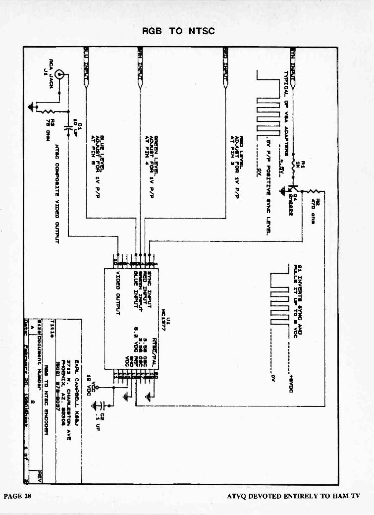
U)
00eC
IMBEM011100>
TYPICAL OP VOA ADAPTERS
R1
R2470 ohm
121
EtniL222
.BV P/P POSITIVE SYNC LEVEL
9V
RED LEVEL
ADJUST FOR IV P/P
AT PIN 3
GREEN LEVEL
ADJUST FOR IV P/P
AT PIN 4
BLUE LEVEL
ADJUST FOR 1V P/P
AT PIN 5
CI
10 UP
RCA JACK
Ji
NTSC COMPOSITE VIDEO OUTPUT
R378 OHM
Gi INVERTS SYNC AND
PULLS IT UP TO S VOC
Wm
/
U1
+8VDC
OV
MC1377
SYNC INPUT
RED INPUT
GREEN INPUT
BLUE INPUT
VIDEO OUTPUT
RTI/PAL
e.ee OSC
3.58 OSC
e.2 VDC REF
SND
YCC
C2.1 UP
V12 VDC
Title
1--ze
AlSi Document Number
EARL CAMPBELL KSSJ
3713 W. CHARLESTON AVE
PHOENIX. AZ. ewes
(502) 278 -OW
ROO TO NTSC ENCODER
2anew
February 20-
111110IShook
1 of
OO44
OC.7

RGB TO NTSC
R G B I TTL TO R G 13, 1V ANALOG CONVERSIONFigure 6 shows a circuit to interface a TTL RGBI output personal computer to the
RGB analog inputs of the MC 1377 If the circuit is used with the values shown, nocoupling capacitors are required to the RGB inputs of the MC 1377 The +5 volt supply tothe 390Q resistors should be very clean to prevent interference on the encoded signal.IC4 is used to simulate 'brown' to be compatible with TTL display monitors.
H IN
VIN
RIN
GIN
1/4 MC74LS86
3
2
MC741504
3
MC74L505
r*-
BIN90-40--
IN 0-0-
COMP. SYNC
COMP. SYNC
+ SY
Row
3300 ?`50pF
+ SY
3300 -r11.50pF
10
MC741505
GOUT
BOUT
white, red, 2.25Yyel, grn, blue,meg, etc.
1.75YDrown ,
grey *--, I .5Y
black -1.25V
RGBI to RGB CONVERTER
Choose propersync for1377 input
From Motorola application notes for the MC 1378
APRIL 1990 VOL. 3 #2 PAGE 29

RGB TO NTSC
MC1377
(a)
1.0 V (pp)
(b(
100%GreenInput(Pin 4)
100%1.0 V (p-p) Red
Input(Pin 3)
(c)
1.0 V (p-p)r- .0., r- 100%
BlueInput
%me,(Pin 5)
Id)
(e)
(f)
(9)
(h)
(i)
PAGE 30
5.0
4.0
3.0
8.2 Max
Min
1.0 Max -1
0
-0.5 M!n
10.5
10.0
9.5
4.35
4.0
3.65
rI I
CompositeOutput(Pin 9)
SyncInput(Pin 2)
I I-I
ChromeOutput(Pin 13)
ChromeInput(Pin 10)
LuminanceOutput(Pin 6)
LuminanceInput(Pin 8)
R.G.B. Inputs should be set up to be 1.0 V p-p forfully saturated levels. This is not arbitrary, since syncand burst levels are internally fixed.
Subcarrier Oscillator. The internal common -collectorColpitts can be free run or it can easily be pulled in bya lightly coupled signal from a "master" into Pin 17.Also, it can be disabled entirely and a 0.25 VRMS signaldriven into Pin 17.
Modulator Phase Angles are quite accurately estab-lished internally. Taking (B --Y) as 0°, burst is at 180°, andthe angle of (R-Y) is 90° ±5.0°. The (R-Y) angle can be"tweaked." For example, 470 41 from Pin 19 to groundwill increase the (R-Y) to (B-Y) angle about 3.0°. PullingPin 19 up will decrease the angle.
Composite Output is dc referenced and can be directcoupled to an RF modulator Inthis case, the 8.2 V regulator output of the MC1377 isdivided down to 5.8 V to provide the zero carrier ref-erence to Pin 1 of the MC1374.
Burst Generation is provided by a sync triggeredramp on Pin 1 and two internal level sensors. Since theearly part of this ramp is used, it is quite accurate.
Sync Input can be varied over a wide latitude butneverless must be applied correctly. The typical ac cou-pled sync signal has very little positive value and willrequire a pull-up resistor to 8.2 Vdc at the input. Thesync input is a 10 kf1./10 kfl divider in the base of acommon emitter stage. For PAL operation, the correctlyserrated vertical sync interval must be used, in order tocontinuously trigger the PAL flip-flop. "Block" verticalsync can be used for NTSC.
(R-Y)(B-Y)(-Y) signals are generated to NTSC values( ± 5.0%) in the input matrices. They are dc clamped atblack level by a sync driven clamp. Burst amplitude isinternally fixed to correspond to sync level, allowing for3.0 dB loss in the chrome bandpass filter. If the filter isnot used, a resistor divider shouldbe inserted between Pin 13 and Pin 10 to provide theproper chrome level. When the chroma bandpass is notused, the (-Y) delay line should also be removed, butthe 1.0 k/1.0 k divider from Pin 6 to Pin 8 should beretained.
ATV°,THE BEST ATVMAGAZINE
ATVQ DEVOTED ENTIRELY TO HAM TV

RGB TO NTSC
CGA & EGA
LOW COST RGB (5 v TTL)TO RGB (1 V LEVEL)
TTL R
TTL G
TTL B
iSmF
ic'e TO R INPUT MC 1377 ADJUST FOR 1 V P -P
15:v
I 0 k I ITO G INPUT MC 1377 ADJUST FOR 1 V P -P
gpf
)01C TO B INPUT MC 1377 ADJUST FOR 1 V P -P
NOTE: CAN USE FIXED VOLTAGEDIVIDER INSTEAD OF POT
TTL R, G, or B
1A1 AC 7 y Ls8.6
Snif
)12-, TO R, G, OR B INPUT OF MC 1377
TO COMPOSIT SYNC INPU i MC 1377
APRIL 1990 VOL. 3 #2 PAGE 31

The w6ORGy Notes
DOES YOUR LOCAL ATVREPEATER RETRANSMITTHE SPACE SHUTTLE
VIDEO?Rosalie White, WA1STO, the
ARRL Educational ActivitiesCoordinator has asked me to compilea list of ATV repeaters that areretransmitting the Space Shuttlevideo and audio from whicheversatellite transponder NASA is leasingduring each mission. She will in turnput that list out with the informationand study curriculum the Leaguesends out to teachers about amateurradio and SAREX-90, the ShuttleAmateur Radio Experiment in 1990.
NASA has offered some time onSPACELINK which reaches around
-4,000 schools.This is a great opportunity to get
young people interested in scienceand technology as well as amateurradio. For ATVers, you mightconsider getting with your localschools and setting up an ATVreceiver for the STS -35 and 37missions. If you use 421.25 at yourlocal repeater all you may have to do isrun a good 70 CM antenna and coaxdown to one of the schools cableready TV sets tuned to cable channel57. If the retransmitted Shuttle videois on 439.25 simplex, use cablechannel 60.
If you have a TVRO receiver, youcan get with your local ATV repeaterowner and work out the link. It isprobably just as simple as running thecomposite video and audio out of theTVRO receiver to the ATV transmitterand setting up a time schedule. Ifthere is an ATV repeater in your areayou can retransmit to it so all canwatch over a wide area, or if there isnot, direct your ATV antenna to aspecific school on simplex. NASASelect Shuttle video is the only otherservice that hams can legally repeat.
AMSAT is looking for some demostations in various parts of thecountry. If you have packet and a nice2 meter set up, contact Tom Clark,W3IWI or Courtney Duncan, N5BF atAMSAT-NA HQ, 850 Sligo Av., SilverSpring, MD 20910. It would also begreat if you had a TV going with NASASelect video.
By Tom O'Hara, W6ORG
Roy Neal, K6DUE, Chairman ofthe SAREX Committee told us at theTropical Hamboree in Miami thatamateur radio might get up to 1 hourof time on NASA Select during STS -35 (May) and 37 (November). Hamswho normally try to work the Shuttleon voice or packet may have theadded benefit of seeing who they arein QSO with at the same time.
Please call or send me thefollowing info right away:
1. ATV Repeater call sign.2. Repeater output frequency.3. Repeater location (nearest
landmark, city and state).4. Repeater antenna polarization.5. Name, QTH & phone number
of a local contact.6. 2 meter ATV calling frequency
STS -37 CHANGED TONOVEMBER
The mission which will haveNASA affiliated amateur radio clubsuplinking ATV for the first has beenchanged from June to November 1.This 5 day STS -37 mission of theShuttle Atlantis, flown by AstronautLt. Col. Ken Cameron, KB5AWP, willhave an orbital track inclination of 28.5degrees which will put most of the USout of range. STS -35, which will havepacket on 2 meters, has been movedto May 9.
The NASA ATV uplink stations inthe southern part of the US will havethe most chance of getting a signal tothe Shuttle. Power in excess of 100Watts and high gain beams withaccurate trackers will be necessary toget P4-5 pictures at the Shuttle.
The time available for amateurradio activities aboard the Shuttle willbe late at night or the wee hours ofthe morning. Since one of thepurposes of SAREX is to directlyinvolve students, it was thought thatthe late hours would prevent this.However when the students at someof the uplink station areas wereasked, it is reported that for a chanceto talk to and be seen by an astronautin the Shuttle they would gladly stayup all night - parents permission ofcourse!
UR WRONG, STS -37WONT BE THE FIRST ATV
IN SPACE!In a way that is correct. ATV and
SSTV are often confused. Two waySSTV pictures were exchanged on 2meters during STS -51-F in July of1985. Slow scan can be used on anyvoice grade radio or hard line circuitsince it takes less than 3 kHz totransmit a black and white still framepicture in 8 seconds or a color picturein 12 seconds. Since SSTV can useany voice grade medium, it can be runon 20 meters (14.230 MHz) and otherHF bands for DX, 2 meters / 70 CMsatellite or local.
SAREXMATEUR RADIO IN SPACE
FIRST PNO-WAV TV FROM SHUTTLE
I tend to label this SSTV indiscussions since it is still frame, andreal time moving video ATV just todifferentiate the two when speakingabout these two distinct types ofAmateur Television. I do not agreewith those calling real time standardtelevision fast scan TV or FSTVbecause there are faster scanningmodes of still frame video. By callingstandard television FSTV, many hamswho know about SSTV think it is ahigher resolution form of SSTV orfaster method of sending still framepictures. They expect to have to geta scan converter interface box to geton and really look at me funny when Isay that you simply hook up thecamera to the transmitter.
PAGE 32 ATVQ DEVOTED ENTIRELY TO HAM TV

The w6ORGy Notes Cont.
WHAT EVER HAPPENEDTO ROBOT RESEARCH?
They are still alive and well in SanDiego. Being one of the pioneers inSSTV and manufacturing probablythe most popular scan converterbrought them all kinds of commercialprojects and business that took mostof their time and effort away from theiramateur line.
Last year at Dayton Rick Samos,KE6DO, said I should take a day anddrive the 110 miles down to their plantand see how they had expanded fromtheir amateur radio beginnings.
Prez. John Stahler, WB6DCN,gave me the tour of their 15,000 sq.ft. facility. They still make the 1200Ccolor SSTV scan converter but otherthan a booth at Dayton every year,they have not been able to put inmuch marketing effort.
ROBOT 1200C repackagedversion flown on the STS 51-F
Space Shuttle MissionSince my visit, there has been a
resurgence in ham radio at Robothowever. They have a demo roomset up with both SSTV and ATV. Agroup of the employees took theweekend Gordon West Novice classand got their licenses.
Many SSTVers have also gotteninto ATV since they already have thecamera and monitors. SSTVers havealso repeated DX pictures over ATVto local hams. So I suggested to Johnthat since some of my ATV customersmight be interested in SSTV and vice -
versa, that we work out some kind ofrep/dealer agreement where I dosome of the marketing in the amateurfield that he has not had time to do.So now PC Electronics will be bothfast and slow.
TE SYSTEMS 180 WATTAMP STILL A MYSTERY
Sorry gang, "the amp will beshipped next week" has become like"the check is in the mail" from TESystems. Every time I have called I
have gotten the same story that theyare very busy with their military orders,but that my 180 Watt amp will go outfor sure next week.
Unfortunately another quarter hasgone by and no amp on the doorstep. I know some of you are waitingfor the results of the testing, ratherthan call me, maybe calling Dave at TESystems saying that you are anxiousto get one of the 4450G's for ATVmight get better results.
As you can guess, manufacturerswho advertise more than a fewmonths ahead of actual productionare a pet peeve of mine.
PAULDON NOW HAS AN18 WATT 23 CM AMP & A
23 CM ANTENNAMOUNTED PREAMP WITHRF SENSED T/R RELAYS
Don Fuller, W2WHK, sent m eboth prototypes to check out on ATVand feed back any required changesand suggestions for the video mode.
Most ATVers have not had therequirement for T/R relays becausecross band repeaters only requiredthat you either receive or transmit on23 CM. However, full duplexflexibility, novice privileges, andpublic service use have raised theneed to transceive simply rather thanhaving to run two 23 CM antennasystems or manually plugging andunplugging the antenna spigot.
PI? 12001M
I 2 GHZ
23 CM Preamp with T/Rswitching
Lets take the PD -1200 TMantenna mounted preamp first. It ismounted in a Hammond 1590C typebox with a bracket and mast clamp.The two N connectors and 12 Vdcpower feedthru when properlyfastened to the mast face downwardto minimize moisture contamination.
23 CM Preamp inside viewThe preamp itself is an imported
shielded module that uses theMgf 1402 GaAsfet. Pauldon
listed the device at 15 dB gain and.65 dB noise figure. The input andoutput tuning is accessible to favorwhichever end of the band you areinterested in.
I measured 10 to 11 dB gain onthe two ATV repeater outputs I cansee from my home QTH on 1241.25and 1253.25 MHz. Peaked at the lowend the roll off was down to 4 dB atthe top, 1300 MHz.
The insertion loss was almost 3dB due to the way the prototype wasbuilt with excessive lead lengthsaround the relays, coax andconnectors. I had to keep in mind thatthese were prototypes and oneshould not expect to find a nice cleanlayout and construction practices -
you should see some of my breadboards...on second thought, no way!There is such a thing as resonantsolder blobs. Don says that theproduction models will not have thehigh insertion loss and a clean lookinglayout. The loss in the prototype canbe added to the measured gain togive an idea as to what can bepossible from the module.
Maximum power into the preampfrom your transmitter is 15 Watts.
APRIL 1990 VOL. 3 #2 PAGE 33

The w6ORGy Notes Cont.
Remember, you can figure thepower at the preamp if you know thefinal amplifiers output power and coaxloss. So if you have 4 dB feed lineloss you could even run a 35 Wattamp in the shack and be OK.
The preamp can make a
significant difference in a snowyreceived picture if the Belden 9913coax run is over 50 ft, and allow you toonly have to run one antenna system,if you also want to transmit on 23 CM.Pauldon offers the preamp with T/Rswitching for $129 or $91 without.
23 CM 18 Watt amp with T/R swThe PD -1200 TR 23 CM linear
amp uses the venerable Mitsubishi57762 power module. This is thesame module as I reviewed in theDowneast Microwave 18 Watt amp. Inboth these units and the later 2 and 4brick amps, they work very well onATV.
The T/R relay sensing keyed rightup when I applied an unmodulated 1Watt of power at 1277.25 MHz, butstarted to chatter when full video wascranked in. Upon inspection of thecircuit I found that there were no filtercaps on the RF detector output and anice video waveform could be seen atthe relay transistor input. I added a .1disc and it seemed to solve theproblem. This circuit will be optimizedfor AM modulations in the productionmodels. Minimum relay pull in was .25Watts in this prototype.
The amp has a fair sized heat sinkthat I think would be fine for mostshacks, with maybe a little air blown onthe fins for the long winded. You canget the amp with an even largerheatsink ,as might be used inrepeater applications, for $11 extra.The amp goes for $169 or $30 lesswithout the T/R relay switching
This amp, like the preamp, hadexcessive insertion loss andnoticeable VSWR which gave lessthan maximum power output that thebricks are capable of. Max power outof this prototype was 14 Wattssaturated with 1.35 in. The same fixon the connectors and relay board inthe preamp should apply to the ampto get the power up into the 15-18Watt area.
I liked having the 5 way bindingposts for attaching the +13.8 Vdcleads to. However those wanting touse it for a repeater might request afeed thru cap instead. Current draw atmax output was 4.5 Amps.
WHAT'S ON THEEQUIPMENT REVIEW
LIST FOR NEXT TIME?Hopefully the TE Systems 180
Watt amp will arrive.I do have an Ireland Antenna Co.
8 ft long fiberglass 70 CM "verticalstick" for repeater and base stationomni applications - I won't tell youwhat their gain claim is but you shouldread it on April fools day. Also I haveone of their little portable half waveantennas with a tuned decouplingnetwork that should be great forKreepie Peepies.
Pauldon has promised one oftheir video samplers. There is a bigneed for a good power/VSWR/RFvideo monitor box to put on theantenna line after linear amps toproperly set them up. For those thatwant to roll their own, check out the1990 ARRL Handbook page 28-8 forthe video sampler. I don't think youneed the chopper amp sectionanymore with most modern D Coscilloscopes today connecteddirectly to the diode output. Also I likeHP 1N5711 hot carrier diodes overthe old 1 N34's.
Jim Rafferty of HRO is loaning meone of the new AEA FSTV 430Atransceivers for complete review. Theimproved model is now at dealers.
The AEA 50 Watt antennamounted amp is still underdevelopment at this time. It mighthave been out now, but the Motorolatransistors that were used in theprototype have been discontinued.
Finding a replacement RF powertransistor is never an easy job. Youcan find variations in parameters evenamong different production runs ofthe same part number from the samemanufacturer that can defy the nimblefingers of even the most experiencedRF tweeker.
The equipment reviews andtelling like it is, as technically correctas we can, rather than like the almostad like reviews you often see in someof the other amateur magazines, hasbecome popular with ATVQ readersaccording to the feedback we havebeen getting.
So ATVQ is looking forequipment reviews from you ATVfans out there. You will need to haveadequate test equipment a n dtechnical background to verifymanufacturers claims as well as what isnot said but needs to be known forour readers to make a well informedjudgement before they buy.
ALL THIS WORK TOREDUCE THE LOWER
VESTIGIAL SIDEBAND,AND SOME ONE WANTS
IT BACK!Those areas using 439.25 MHz
and getting interference from FMrepeaters have temporarily alleviatedthe problem by going to high -sidelocal oscillator injection in the repeaterdownconverter to invert t h esidebands and retune their VSB filterto favor the lower vestigial sideband.However, this usually results in hardlyany audio and color from transmittersthat are designed to roll off the lowerVSB.
On the PC 1 Watt transmitters,two RF stages are modulated withvideo. This is done to get at least 20dB depth of modulation with goodlinearity down close to zero carrier.The phase is shifted between the twostages to buck out the lowersideband anywhere from 6 to 20 dBdepending on the parts tolerances.To go back to equal sidebands it is arelatively easy change.
PAGE 34 ATVQ DEVOTED ENTIRELY TO HAM TV

The w6ORGy Notes Cont.
The end of the 22 Ohm resistor atthe 2N3734 modulator emitter thatfeeds the RF driver collector getsclipped and reconnected to a near byB+ pad.
/00
move .4.Tot 5-T
4./3.0)./Tie2N3739
Z2 curli/f+
c7
TC70-/
.47
Li420LB i'dYLT6
MRF555
This effectively makes only thefinal MRF555 transistor videomodulated. The only down side tothis is that the white level might becompressed a little, but will be hardlynoticed in most camera video scenes.With modulated transistor RF poweramps, it usually takes two stages toget at least the desired 20 dB depthof modulation.
THINKING ABOUTPUTTING UP AN ATVREPEATER? PART IIIOK, you have checked out the
site, coordinated the frequencies,gotten the antenna(s), feedline andfilters, now for the fun part, therepeater itself.
Repeaters tend to evolve andchange over a few years so a modularapproach makes much more sensethan putting it all in one chassis orenclosure. It also allows changes andadditions to be made easily withouthaving to make many trips to the hilltop to bring the system down to thebench for major surgery. One trip tothe hill to sub or plug in a smallmodule also saves the wrath of theflock that have no patience for downtime.
To start, there are 3 basicmodules: The transmitter, thereceiver and the control/ID units.Each should be mounted in it's owncompletely shielded box withappropriate coaxial connectors forinter -connection. They can be boltedto 19" panels if they are to be put intoa rack at the repeater site. I like theHammond diecast aluminum boxes,but there are others that havecomplete contact along all seams.The shielding is absolutely necessaryto keep your transmitter, and anyothers near by, from desensing the
APRIL 1990 VOL. 3 #2
receiver. You would be surprisedhow RF can get through cracks inchassis and less than 100% shields incoax.
It is possible to shield and filtereffectively. I have seen interferencefree weak signal video at repeaterssharing the same building andantenna structure with five or more 70CM FM repeaters with associated linksand control, and even some withmegawatt UHF TV stations.
DC lines can be attached to 500to 1000 pF feedthru caps. Audio andvideo lines should be coaxialconnectors with bypass capsmounted right at the connector withas short of lead length as possible. I
use 220 pF for audio lines and 100 pFfor video lines.
I suggest double shielded oraluminum foil + braid coax for allinterconnections. Any lead that is not100% shielded and bypassed at theconnector is likely to become a poorbut significant antenna to conductunwanted RF into the box.
Careful attention must be made toall RF internal connections as well asconnector assembly. Any VSWR inthe transmitter that makes thereflected energy travel on the outsideof the the coax and over every nookand cranny of the box can eventuallyreach the receiver. Many do notrealize that a good VSWR readingoutside of the transmitter box doesnot mean that the interconnectingcoax from the transmitter to thechassis connector is good. Coaxialintegrity in the receiver is alsoimportant to keep unwanted groundcurrents from sneaking inside. Sokeep the RF inside the coax as muchas possible with very short centerconductor and shield leads. I doesnot make much sense to pay the buxfor a good quality VSB filter to have itbypassed by poor shielding andconstruction practices.
THE RECEIVER: All ATV repeaterreceivers should be crystal controlled.Even a temperature stabilized freerunning oscillator will slowly changefrequency with age, dustaccumulation, oxidation, etc. Oncethe machine is up and operating well,you probably will not want to makeseveral trips to the hill top to justtweek the LO back on centerfrequency.
ATVR-4 ReceiverOutputs from the receiver module
should be one or two compositevideo and one line level audio. Thereceiver composite video outputstandard is 1 V peak to peak into 75Ohms just like it is for cameras andother video devices. It is nice to haveone video output to go to thetransmitter, and another one to go toa local monitor to aid monitoring andadjustment while at the site. The lineaudio is also about 1 volt peak to peakbut operates into a 10K highimpedance or 600 Ohm load.Another nice feature is to have theaudio squelched to keep the audionoise down with the weaker videosignals that can key up the horizontalsync operated relay. A local speakeramp is also of benefit for monitoring atthe site.
For an inband repeater I suggestusing a separate or well decoupledpower supply from the one used bythe transmitter. There could be someconducted interference on thecommon power supply lines, and thefinal amp varying load with videomodulation could set up a feedbackpath through the receiver.
AVRCIIS v--2!
---31111111111111NIMM7Xtal Downconverter &
Receiver in Diecast BoxI recommend single frequency
conversion directly to the standard45.75 MHz TV IF rather than to achannel 3 receiver. A channel 3receiver has a free running LO thatcan drift, and also more possiblesystem mix and image products fromstrong near -by transmitters.
PAGE 35

The w6ORGy Notes Cont.
The 45.75 MHz TV IF SAW filtersare made to favor the lower vestigialsideband. To properly receive thestandard upper VSB, the localoscillator in TV tuners is above thereceiver input frequency to invert theVSB. So if you have a downconverterfor channel 3, it is not just a simplematter of moving the local oscillator up15.5 MHz to output on 45.75 MHzinstead of 61.25 MHz. It actually hasto be moved up 107 MHz.
Many new repeater receiversystems start out having way toomuch system gain which ends upbeing swamped by the stronger ATVstations and makes it moresusceptible to intermods. Total gainshould be just enough to start thevideo AGC voltage to move on noise.Any more gain does not improvesensitivity, it just pumps up the AGCwith the amplified noise floor. Addingpreamps ahead of a good preamp inthe downconverter most often doesnot improve sensitivity but rathergives more intermod interferenceproduced in the overloaded first mixeror following stages.
To check your system justmeasure the video IF AGC dcVoltage, not the RF or delayed AGC,with the downconverter turned offand then see if it changes muchwhen turned back on. Ideally thevoltage change should not be morethan 1/10th of what you wouldmeasure with a very strong signal.
So if you do use a channel 3receiver, a downconverter with 25 dBgain and also a preamp, you areprobably in for trouble. The noisefloor in most TV systems is no betterthan 1 microvolt due to the 3 MHz 3dB bandwidth. The preamp stageshould have the best noise figuredevice possible to get as close to the1 uV as you can. But you may have todump some gain with resistiveattenuation between t h edownconverter and the receiver toalso have wide dynamic range. Youwant to get the weakest signals but atthe same time be able t oaccommodate that guy 2 miles awaywho won't turn off his 100 Wattafterburner and wonders why therepeater picture is rolling a n ddistorted from clipping.
A channel 3 receiver will also havea delayed AGC RF stage to give a totalAGC range of at least 60 to 70 dB. It is
PAGE 36
called delayed AGC because it doesnot start until the picture is snow freearound 100 to 200 uV. There isusually a pot to set the starting point.The first stage in the TV tuner isdesigned for best noise figure at fullgain to get the best picture to noiseratio. But once the signal is strongenough, it's gain can be cut back bythe delayed AGC action withoutdegrading the picture. FET's anddual gate GaAsfets are preferred forthis because they have higherdynamic range even when the gain iscut back than most bipolars.
With systems that have directconversion to the 45.75 MHz IF, adelayed AGC amplifier stage has to beadded to do the same job as thechannel 3 tuner. Just the video IFAGC is not enough. I use a MRF901to do this in the VRC45a IF/receiversahead of the SAW IF filter.
For those that want even moredynamic range or have problems withlimiting on very strong signals, a2N2222 transistor can be used toAGC the downconverter preampstage. This is just an emitter followerin the +8V supply line to preventloading down the RF AGC. Thenormal RF AGC voltage goes fromabout 7 Volts no signal to 2 Volts with10,000 uV in the VRC45a. The drainvoltage will follow the emitter followervoltage and directly decrease it's gainwith increasing signal.
TVCX -70
cPRedIAIP
744-E
.001 Cur 12E511:T0aaNt E3v Sive
100 ANv /NSc.crrtie 2/1/12.22._
2W
W e-253cot
NEW/
If you have a different IF module,check it's normal range to see if youcan do the same thing.
To implement this modification forwider dynamic range, cut the preamps100 Ohm drain resistor on its +8Vside and lift it up. Connect the2N2222 emitter lead to the cut end ofthe resistor and the collector to the+8V pad. The base needs some strayRF filtering in series with it. I put a Pinetwork with a 1K in series and .001mF discs on each end to ground. Thedisc caps can be made into solderposts for the resistor, base and wire tothe RF AGC test point pin in theVRC45a receiver IF. Solder one endof the disc cap standing on end to theground plane. route t h einterconnecting wire away from anycoils or other parts of the circuit.
Bill Barefoot, W3UQJ, Ham -TVATVQ DEVOTED ENTIRELY TO HAM TV

The w6ORGy Notes Cont.
ATV IS COMING ALIVE INSOUTHERN FLORIDALast February we took a few days
to go to the Tropical Hamboree inMiami. MaryAnn and I had never seenFlorida, so this was a greatopportunity to give an ATV talk andexhibit at one of the larger hamconventions, plus take an extra day tosee the area. Besides there isnothing like some nice 80 degreeweather in the middle of winter evenfor a Southern California native.
The crowd was estimated at15,000 with one large area forcommercial exhibitors and two othersfor the flea market. It is like a miniDayton but all indoors.
Tom Middleton, WB4CKY had anATV transmitter running from theHollywood Radio Club booth whichwe received at our booth at the otherend of the hall. I could not resistputting a sign up over the TV saying"Live from Hollywood". That isHollywood Florida of course.
John Sims, KA4ZAY gave a nicedescription of ATV activity in thegreater Miami area and progress onhis ATV repeater at the ATV talk. Ithas been burning in on a tall buildingin Hallandale in preparation to put it upon two of the tall TV towers near theDade - Broward county line. It shouldbe up and running with 434 in and421.25 out by the time you read this.You can find John usually on Mondaynights around 7:30 on 146.430 or146.555.
John's machine went split sitewith a 10 GHz Gunnplexer link
between 2 adjacent 1000 ft TVtowers. He wanted to be up andrunning for the Tropical Hamboreebut one of the Gunn diodes went out,and also he was not able to get rid ofall the strong channel 4 TV signal outof his 70 MHz IF. He is writing up anextensive article with photos for a laterissue of "the 0".
They will have a Weather radarfeed from the National HurricaneCenter in Coral Gables when thestrong storms threaten the area andlocal emergency services groupsneed to see exactly where the cellsare on a continuing real time basis.Space Shuttle video will also beavailable.
John also reports that StevenGrey, KC4NOL is putting ATV on aJet Ski. What will ATVers come upwith next?
L -R: Lionel, KC4CLD; Pat (no callKA4GAQ; Manny, KC4LFO & Rita,
The first ATV repeater in theMiami area is actually in Hialeah puttogether by Armando Fernandez,KA4GAQ. Input is on 426.25 andoutput on 923.25 MHz. His 14 Wattoutput was getting good pictures forabout a 20 mile radius. I told himabout the Hi -Spec 200 Watt 33 CMtube amps, and that I had just talkedto Ott, W4WSR, the owner. His eyesseemed to light up at the prospect ofa new high power amp, and said thathe intended to give Ott a call.
I have been talking to Armandofor many years and was glad to havethe chance for the old eye ball QSO.He writes the ATV column inRadioscan Magazine. This is aSpanish language ham magazinewhich covers both the Americancontinents. US hams might be verysurprised how many Central andSouth Americans are into AN. Quitea few came up for this convention.Radioscan is coming out with anEnglish version which will be givenout as a free complimentary copy atDayton.
When we told Rita Vianney,KC4MJG, Radioscans AdvertisingDirector how much we enjoyed someof the Cuban food, the next day shesurprised us with 4 plantains to takehome and a recipe on how to fry themup. It seemed that when we weren'ttalking ATV we were eating. Besidesthe great local restaurants, theTropical Hamboree exhibitorscommittee really made sure we werewell fed. It was a 5 pound week!
VW.
yet); Luis, KC4NOF; Armando,KC4MJG.
APRIL 1990 VOL. 3 #2 PAGE 37

The w6ORGy Notes Cont.
WHAT WILL YOU HAVETHIS YEAR AT THE
DAYTON HAMVENTIONATV FORUM?
Captain Video, Henry Ruh,KB9FO will lead off with hisintroductory talk on ATV entitled"Helping Ham Radio to be Seen", withsome time for Q & A. Carl BerryK5MWN will show some slides andtape on what it is like to fly by video asif actually in the cockpit of his R/CModel airplane. Bill Brown, the wb8-ELKman, will show a 10 minute videotape composite of all the balloon,rocket and kite ATV he has beeninvolved in the past few years, and tellof future voyages to the edge ofspace. We hope to have a SAREX-90up -date for you also.
The ATV Forum will be in room 3Saturday afternoon at 2:45 until 5 pmjust like previous years. Come by andjoin in. All your favorite ATVmanufacturers will be at the samebooth locations to show you what isnew and wonderful.
Don't forget to bring someantennas for the HamventionAntenna Measuring contest,everyone it seemed won a prize lastyear .... stick a screwdriver in aconnector and see what it does, HI!
Spring is here, so it is time to thinkabout those new antenna andfeedline projects as the weather meltsthe ice. The Dayton Hamvention andthe Central States VHF/UHFConference Antenna Measuringcontests are good places to checkout new designs or see what the oldones really do. Central States thisyear will be held at the Wichita KSMarriott Hotel July 26 -29th. ContactJon Jones, NOOY for more info.
After Dayton, you can catch us atthe Southwestern Division AR RLConvention in San Diego August 25-26. We had planned to be at theARRL National Convention in KansasCity in June, but our son Rick,N6UEM, is graduating from Cal Polythat weekend. Henry Ruh, KB9FOwill be there at the ATVQ booth andgiving the ATV talk.
73 , Tom O'Hara, W6ORG2522 Paxson LaneArcadia CA 91007
(818) 447-4565FAX (818) 447-0489
PAGE 38
R/C HELICOPTER ATVBy Mike
For the past few months, I'vebeen working on the design of asmall ATV package suitable formounting on a radio controlledhelicopter. I had researched severalpossibilities and decided t ohomebrew a transmitter that wouldadequately meet the size and weightrequirements for a medium sizedmodel (40" main rotor diameter, .40powered). Most model helicopterscan conservatively carry aloft about40% of their weight in the form ofpayload, depending on temperature.
The model Hughes 300 weighedin at just under 6 lbs. I set a targetweight for the payload of 1 lb. whichwould put it well within this range. Atthis weight ratio, the pilot would havethe freedom to engage in the usualacrobatics that R/C helicopter pilotsare known for without over stressingthe model. The package weighed atotal of 14 oz., with a 7 oz. UnidenVM110 CCD B & W camera and a 7oz. NiCad/transmitter package (1.25"x 2" x 3.75")
The 50 mW output of thetransmitter proved to be sufficient forline of sight snow -free operation upto 1/2 mile on 70 CM.
Once the Package wascompleted, it was time for the maidenvoyage. Since I still consider myself abeginner at model helicopter flight, I
decided that I would enlist the help ofa more seasoned veteran of that type
Henkoski, KC6CCCof flying. Dave Herbert is n obeginner at R/C helicopters, he hasflown many of the miniatures used inmovies like "Blue Thunder", andserves as a technical consultant forthe motion picture industry.
The day of the big flight arrivedand the conditions were excellent,with no wind and a temperature of 72degrees. The package was installedwith very little problem utilizing plasticties. The transmitter pack wasmounted atop one landing skid andthe camera on the opposite skid. theantenna used was a simple dipoleplaced just under the bubble cockpit.
Then the moment of truth: thehelicopter lifted off with ease. Theoverall operation was better than Ihad expected. We were treated to abirds eye view of the surroundingvalley and flight field below. The onlyproblem seemed to be a nintermittent loss of sync when themodel was airborne at high speed.This was later attributed to thevibration of the BNC antennaconnector.
I was very pleased with theoperation, and intend to up grade toa higher resolution color camera andpossibly try the new one Watt TXA5-RC transmitter from PC Electronics. I
would encourage other Hamsinterested in R/C modeling to try theirhand at this interesting way ofmerging the two hobbies.
ATVQ DEVOTED ENTIRELY TO HAM TV

Pocket Power ConverterMODEL PC100 + - $ 149 ppd
The Pocket Power Converter is the perfect way tooperate your AC powered computer or peripheralsfrom battery power.
Advanced technology and solid engineering havecome together to make the Pocket Power Converterthe smallest, most versatile and most reliable productof as kind.
Builtin features like instant -on, ultra high efficiency,complete electronic protection, low battery alarm (at10.7 volts), and low voltage shutdown make it troublefree and simple to use.
WA6SVT VIDEO PROCESSOR
INDEPENDENTLY CONTROLVIDEO L SYNC LEVELS
CAM ADJUST COLORBURST LEVEL
SET WHITE CLIP LEVEL
Specifications
Voltage In: 10-15 VDCVoltage Out: 115 VAC RMSOutput Frequency. 60 HzPeak Power: 200 WattsConstant Power: 100 Watts
Height: 1.2° (3.0 cm)Width 3.5' (11.5 cm)Length 4.5' (9.0 cm)Weight. 14 oz. (400 grams)Warranty' 6 months
Assembled / TestedgitPC Board
ELKTRONICS12536 T.R. 77Findlay, OH 95890(919) 122-8205
$39$29$ 7
TWO SIGNAL ENHANCEMENT EFFECTBill Parker W8DMR
Have you ever witnessedthe phenomena whentwo weak ATV signalsappear on the monitor atthe same time?If only one signal is observed at
a time, practically nothing can beseen on the monitor. However, ifboth signals are observed simul-taneously, more picture Informa-tion may be observed. WHY?There are two factual reasons to
explain the weak two Signal En-hancement Effect (SEE). If, forexample, a 1 volt p -p sinewave is
displayed on an oscilloscope, thenadd another 1 volt p -p sinewave ofa slightly different frequency.There will be peaks that are 2volts high and nulls of zero volts.It is a form of beating. This des-cribes the line -pairing often ob-served when two modulated TVsignals are operating on the samechannel. The broadcast industrypurposely offset the carriers by 15Khz to aid in reducing this effect.In nearly all AM TV receivers
there is a diode detector (rectifier)used for AM modulation recovery.If a received signal is low enough
SEE YOUR NAME INPRINT! SEND YOURARTICLES AND NEWS INNOW!
in amplitude, diode signal rectifica-tion is poor until the signal levelapproaches a level the diode canoperate on. When both weak sig-nals are present, the signal level(when both are adding) is suffi-cient to display the observed high-er contrast. The adding of the twosignals and the higher signal levelsupplied to the detector for moreefficientdemodulation explains themysterious weak two signal enhan-cement effect. SEE, I told you so!
SUBSCRIBETODAY
APRIL 1990 VOL. 3 #2 PAGE 39

P.C. ELECTRONICS 2522 PAXSON LANE ARCADIA CA 91007-8537 USA
TOM (W6ORG) & MARYANN (WB6YSS) O'HARA (818)447456524 hr FAX order line (818) 447-0489 rilir
VISIT OUR BOOTH AT DAYTON # 355
ELECTRONICS
ONLY
$329* Delivered
Value plusquality from over25 years in ATV
470,.350 ION: AMATEUR TEEEViStO
RECV TUNE TRANSCEIVER
TC70-1d TRANSCEIVER
AMATEURTELEVISIONMADE EASY
WITH THE 1990 TC70-1d YOU GET:1. Improved sync stretcher with both adjustable blanking pedistal and sync controls.
Allows you to better set up any amplifier for optimum video to sync ratio and stretch the sync without cutting offthe sound by driving it into saturation. By setting the sync tip to just 1.5 dB (86%) of your ATV amplifiers satura-tion power, you get enough headroom to be able to increase the sound injection to -15 dBc and make it go fartherwithout being chopped up at the sync rate (sync buzz). -15 dBc is the FCC limit for TV translators or those that donot run separate sound transmitters. The limit is due to the fact that the sound will bottom out at a fully modulatedwhite level (12.5%) when the sound is added to the video waveform.
2. SET UP YOUR CAMERA PICTURE IN THE MONITOR WHILE RECEIVING ANOTHER ATVER.Camera video is now present at the transmit video monitor output while in receive. While watching other stations,you can point and set up your camera well before it is your turn to transmit. When in transmit you still areswitched to seeing the actual detected video present at the antenna output. This is the only true way to see whatis really being transmitted after it passes from your camera and all the stages of the transmitter.
WITH P.C. ELECTRONICS YOU ALWAYS GET:Total prices listed delivered to you via UPS surface with no fine print handling, shipping or charge card costs.The widest variety of ATV gear available with most telephone orders shipped within 24 hours.We are your one stop ATV source for equipment and information. We have been telling it like it is over 25 years.No one else has our service policy without a time limit. Parts have different life times and in circuit stressratios. We have even repaired a 12 year old TC-1 at no charge because we could see no customer or normal
use reason why a .1 disc ceramic cap decided to open up. Customer caused service on the TC70-1 is only $40 +parts cost and most repairs are turned around within 3 days after we receive them, we want you back on the air!
COMPLETE 70CM ATV STATION 4/90
YOUR HOME TV CAMERAOR CAMCORDER WESTOCK 439.25, 434.0 & 426.25
"Ural.TC70-1...$329
+ATV Transceiver>1 WATT P.E.P. 13.8Vdc
Pwr. Sup.
Mirage D15N $159(optional) 15 watts RF out.Mirage D26N $219(optional) 50 watts RF out.Mirage D100TVN..$319(optional) 70 watts RF out.
KLM 440-16X 14dBd $119KLM 440-10X 11dBd $68KLM 440-6X 8.9dBd $57
CALL (818) 447-4565 NOW AND ORDER YOURS! MOST ITEMS SHIPPED WITHIN 24 HOURS

P.C. ELECTRONICS 2522 PAXSON LANE ARCADIA CA 91007-8537 USATOM (W6ORG) & MARYANN (WB6YSS) O'HARA (818)4474565
24 hr FAX order line (818) 447-0489 w7 v.
ELECTRONICS NEW TX70-1A AND RTX-70 TRANSMITTERThe family of full feature ATV transmitters for home, link orrepeater use is now complete. We have models for all 3 of thepopular ATV bands - 23, 33 and now 70 CM. TX & RTX 70 available May 90
El+18301P 11.3341StMfr
73 111,41
TX SeriesFeatures found on all 3 transmitters:
1. >1 Watt pep with adjustable sync stretcher to properly match amateur linear amps. Sets the blanking pedestal forproper video to sync ratio to compensate for the linear amps high power gain compression curve.2. RF detector right on antenna output to see what is really going out on the air and that your video gain, focus, etc.throughout the whole transmitter is set up correctly. Detected composite video monitor outputs to a RCA jack intransmit, and loops thru in receive to enable camera set up before flipping the transmit switch.3. Independent gain control of mic and line audio to enable external mic mixing with VCR or camera mic audio. Newtemperature compensated 4.5 MHz sound subcarrier generator with line audio pre -emphasis and soft limiting betweenthe broadcast standard 25 kHz average & 40 kHz peak deviation.
CHOOSE THE TX SERIES FOR HOME AND PORTABLE USE. Has built-in RF T/R relay switching for easyconnection through a BNC cable to the companion TVC downconverter. Rear panel video & audio jacks for VCR orCamcorder, or use front panel VHS camera jack. Mic & push to look jacks in front. Shielded cabinet 7x7x2.5", 1.6 lbs.
NEW TX70-1 A has 2 frequency capability in the 425-440 range, 1.5 W pep on sync tip typical output $279one crystal included - we stock most used 439.25, 434.0 & 426.25, plus 427.25 & 425.25. 2nd crystal add $15.
TX33-1 single frequency - specify 910.25 the most common simplex, 911.25 or 923.25 MHz $329TX23-1 single frequency - specify 1289.25 the most common simplex, 1277.25, 1265 or 1253.25 MHz $329
CHOOSE THE RTX SERIES FOR DEDICATED REPEATER AND LINK USE. Uses same transmitter in acompletely shielded Hammond 1590D diecast aluminum box but without T/R switching.
NEW RTX-70 specify repeater or link output frequency, 421.25 MHz most popular for inband output $299RTX-33 specify frequency - 923.25 MHz is the most used crossband repeater or link frequency $329RTX-23 specify frequency - 1253.25 MHz best first repeater output crossband freq., then 1277.25 MHz $329
omniantenna 80 watt 70cm Inband ATV REPEATER Example
439.25 or 434.0 MHz ATVR-4 Receiver Control421.25
TVCX70ATV
VRC45aIF/ATV
VSB9971 FILTER RG55
coaxxtal cony receiver
COaX1590D box k
590D boxvideo Video
r RIA.custor.
v titC11,31,04.39532 1..AutCr:10(11 C.ok 0008
RTX Series
Transmitter MHz
omniantenna
9913coax
VSBMirage
audio IDer -D1 00TVR-10-
1
11-tx
80w amp +13F.8ILvTdEcR-..--1:r. VOR-2
0. @20 Amps
Select an ATVR Receiver (catalog pg 4) & a RTX Transmitter for the bands you want, add the appropriate linear amp,VSBfilters & antennas, ID & VOR-2, power supply and coax for your own repeater. We suggest low in / high out for crossband.VOR-2 Video Operated Relay board...$45, keys RTX upon detection of horizontal sync. 10 min. & end oftransmission momentary relay for switching to video ID to meet FCC regs. Contact Bill Brown, WB8ELK at (419) 4228206for the VDG-1 video IDer directly. 33 & 23 CM Amps - Downeast Microwave Bill (207)9483741, Omni gain Vertical Ant -NCG Co. Bruce (714) 6304541, VSB Filters - TX/RX Systems Jon (716) 5494700.CALL TO DISCUSS YOUR APPLICATION & TO GET A COMPLETE CATALOG NOW!
-o0
RTX-70xmtr

ELECTRONICS
P.C. ELECTRONICS 2522 PAXSON LANE ARCADIA CA 91007-8537 USATOM (W6ORG) & MARYANN (WB6YSS) O'HARA (818)447-4565
24 hr FAX order line (818) 447-0489 Mfa isNEW SMALL TXA5-RC 1 WATT
70 CM VIDEO TRANSMITTER
As a result of the successes of the KPA5 used on 3 of the WB8ELK balloon flights,various kites, rockets and R/C aircraft, we came up with a small video only board tobetter fit into these crafts, but can also be used for any ATV application.
TXA5-RC FEATURES:1. Size only 2.25 x 4.0 inches. Weight 2 ounces. Draws 250 mA at full power with 13.8 Vdc.2. Comes with single crystal on your specified frequency: 426.25 most popular for R/C, or any of the other standard ATV
frequencies of 439.25, 434.0 or 427.25 MHz are stocked.3. Although not necessary for the R/C application, it does have the sync stretcher in case it is to be used with a higher
power amplifier and a sound subcarrier input to accept the FMA5-E. This way it has the flexibility to also be used inportable public service applications, etc., where all of the features of the KPA5 are not necessary but still could beadded.
4. Introductory price of $129. Available now.4/90
UNIDEN VM110 CCD BLACK AND WHITE CAMERA IS HERE!NEED A LOW COST PER CRASH CAMERA FOR YOURR/C MODEL, KITE, BALLOON, OR IN THE SHACK ID?THE VM110 IS ONLY $125 delivered.The camera was made for home security applications where low cost, ease ofinstallation and use are more important than high resolution, color, or low lightlevel capability. Depth of field is less than 1 foot to infinity and has auto iris.View angle is 40 degrees with the included lens system.Size is 4.7 x 3.9 x 2.2 inches, weighs less than 7 ounces.Requires 11 to 14 Vdc at 200 mAHorizontal resolution is 120 lines with 19440 pixelsCamera with 4.8" monitor model VM100....$175Camera, monitor with intercom audio model VM200 ...$199
KOYO TVC-4000-2 600 LINE RESOLUTION BLACK AND WHITE CAMERA $199Low cost for those who cant afford a camcorder yet, or want to leave a camera on ablack and white call card for working DX.120 Vac 60 Hz line locked 2:1 interlace600 lines horiz. res. f1.6 C mount lens included. 4 x 2,4 x 8.5 inches, 1.7 lbs.
COLOR SSTV WITH THE ROBOT RESEARCH 1200C $1295 deliveredStill the standard for slow scan television around the world. Send and receiveefficient 8 sec. Black and White or 12 sec. color with your HF SSB transceiver forDX pictures, VHF/UHF FM for local, or repeat SSTV DX over local ATV. 6 picturememories, 4 transmission formats - 120 & 240 lines, accepts any composite videoor use internal color bars, 262,144 color combinations, parallel I/O printer port,outputs to composite video or RGB monitor or ch 2/3, and many other features.WE ARE NOW ROBOT'S REP/DEALER FOR AMATEUR SSTV

ELECTRONICS
P.C. ELECTRONICS 2522 PAXSON LANE ARCADIA CA 91007-8537 USATOM (W6ORG) & MARYANN (WB6YSS) O'HARA (818)447-4565
24 hr FAX order line (818) 447-0489 rair
TIME FOR A NEW DOWNCONVERTER?WE HAVE TUNEABLE OR CRYSTAL CONTROLLED BOARDS OR READY TO GO GaAsFETDOWNCONVERTERS FOR ALL 3 OF THE POPULAR ATV BANDS - 70, 33 & 23 CM.
Tunable wired and tested boards, req. 12 Vdc, cabinet, connectors etc.:
TVC-2G 420-450 MHz to ch 3 $49TVC-9 902-928 MHz to ch 3 $59
aC 23201101PC,21 221130111 LAW
1112211. 121002
USA
/1.2 Rieirir11T223131 t2323,,0, C3C332. C' .2
rtU VI22
Tuneable ready to go in a shielded cabinet with wall plug power supply:TVC-4G 420-450 MHz to ch 3 $89TVC-9G 902-928 MHz to ch 3 $99TVC-12G 1240-1300 MHz to ch 8 $109
Crystal controlled wired and tested boards:TVCX-70 specify freq. in 420-440 range to ch 3 or IF ...$99TVCX-33 " " " 902-928 " " " " " " ...$109
TVCX-23 " " " 1240-1300 " " " 10 " " ...$129Ready to go in 1590C diecast aluminum box add $30
COMPLETE CRYSTAL CONTROLLED RECEIVERSDesigned for dedicated repeaters or links, these can also be used bythose who want to have composite video out to drive a monitor.2 composite video outputs, 8 Ohm speaker and line audio outputs.Audio has a variable squelch control. Requires 12 to 14 Vdc @ 250 mA.Contains TVCX board and VRC-45a receiver boards in a 1590D box.ATVR-4 specify 420-440 frequency $299ATVR-9 " 902-928 " $309ATVR-12 " 1240-1300 " $329
VRC-45a 45.75 MHz IF/receiver module for those who want to packagetheir own system for composite video monitor output $99
4190
SPRING IS TIME TO REPLACE THAT OLD RUSTY SKYHOOK WITH A NEW KLM BROADBAND ATV ANTENNA
KLM 440-6X has 8.9 dBd gain, vertical or horizontal polarization rear mount ona short 28" boom. Ideal for point to point, fixed at a repeater or small enough tobe portable at public service events to minimize multipath ghosts and get somegain at the same time. Wide 60 degree beam width. Type N female..$57de1.
KLM 440-10X has 11.2dBd, 64" boom. Rear Horiz or Veil mount same as 440-6X, just longer for a little more gain and multipath rejection $68 delivered
KLM 440-16X replaces the 440-27 - 10.5 ft boom length, full 420-450 MHzbandwidth, and much more rugged .
Measured more than 14 dBd at 1989West Coast UHF Conference. As with all 3 KLM antennas the 50 ohm balun isincluded, type N female connector $119 delivered
ATV antennas must have broad bandwidth in addition to high gain and low VSWR. Few other antennas work well atboth 439 and 421 MHz. The three KLM antennas listed here fit the requirement and have a long history of ruggedoperation with ATVers. The gains listed have been proven out at VHF/UHF conference antenna measuring contests, theyare not marketing hype. All KLM antennas listed here take up to the maximum legal power limit. Balun or matchingnetwork with female type N connector included. Price includes UPS surface shipping anywhere in the contiguous USA.

ii THE
BATCARE YOU A MEMBER ?
YOU CAN BE FOR AS LITTLE AS $12 PER YEAR.($19.50 PER YEAR TO RECEIVE YOUR MAGAZINE BY AIR MAIL)
FOR THIS VAST SUM YOU WILL RECEIVE FOUR ISSUES OF THE CLUB'SMAGAZINE, CQ-TV, WHICH IS ALWAYS PACKED WITH UP-TO-DATEPRACTICAL INFORMATION ON ATV DESIGNS. PRINTED CIRCUIT BOARDSAND SPECIAL COMPONENTS ARE ALSO AVAILABLE FROM THE CLUB ATREDUCED RATES. A SERIES OF HANDBOOKS HAVE ALSO BEEN PUBLISHEDBY THE CLUB, DEALING WITH ALL ASPECTS OF ATV, FROM SETTING UPYOUR FIRST STATION, TO THE LATEST IN STATE-OF-THE-ART MICROWAVEGEAR. MANY OTHER SERVICES AND FACILITIES ARE AVAILABLE TOMEMBERS AND PRACTICAL HELP IS AVAILABLE ON ANY TV RELATED TOPIC
FOR FURTHER INFORMATION AND MEMBERSHIP APPLICATION FORMS ETC,CONTACT OUR UNITED STATES AGENT DON MILLER AT:
WYMAN REASEARCH INC, BOX 95, WALDRON, INDIANA 46182TEL: (317) 525 6452
(CHEQUES PAYABLE TO WYMAN RESEARCH PLEASE)
COMING IN THE NEXT ISSUE OfCO -TV
CONSTRUCTION ARTICLES FEATURING: A SUPER -VHS TO RGB CONVERTER,A 24CM PHASE -LOCK -LOOP EXCITER FOR ATV, A VERSATILE CAMCORDERCABLE ADAPTOR, A HIGH PERFORMANCE PREAMP FOR 24CM AND COLOURCORRECTION METHODS. PLUS LOTS OF NEWS, DX -TV NEWS, LOGICCIRCUITS, USING OSCILLOSCOPES, ETC. MAKE SURE YOU GET YOURCOPY, SEND YOUR SUBSCRIPTION TO DON AND JOIN THE 2500 OTHERATV'ers WORLDWIDE WHO MAKE UP AND ENJOY BEING A PART OF:
THE BRITISH AMATEUR TELEVISION CLUB

Antenna -pointing guideThe following program is suggested as a general aid in calcu-
lating antenna -pointing information. It can be used with nearlyany computer programmable in BASIC. Although some com-mands are more specific to the MS-DOS BASIC language thanother dialects, you should not have to make many changes.
This program is available both as an ASCII text file(BESAT.TXT) and as a BASIC program file (BESAT.BAS) in theBroadcast Professional Forum data library on CompuServe. Itmay be obtained without charge, beyond access time, by enter-ing GO BPFORUM at any prompt and downloading from datalibrary DL4.
This program allows determination of proper pointing anglesfor the earth -station antenna in the Northern Hemisphere,given the antenna site location and the satellite location alongthe geosynchronous arc.
10 CLS: PRINT "NORTHERN HEMISPHERE ANTENNAPOINTING GUIDE": PRINT
20 PRINT "Express all entries in decimal degrees Northlatitude,"
30 PRINT "or West longitude, i.e., 12 degrees, 30 secondswould"
35 PRINT "be entered as 12.5."40 R=3963: H=22300: REM earth radius satellite altitude50 PRINT: PRINT "Enter SATELLITE location."60 LINE INPUT "Degrees West longitude:"; SL$:
SL=VAL(SL$)70 IF SL=0 THEN SL=.001
80 PRINT: PRINT "Enter ANTENNA SITE location."90 LINE INPUT "Degrees West latitude:"; WL$:
WL=VAL(WL$)100 IF WL=0 THEN WL=.001110 LINE INPUT "Degrees North latitude:"; NL$:
NL=VAL(NL$)120 IF NL< 0 THEN PRINT "Program valid in Northern
Hemisphere": PRINT "Modification needed for SouthernHemisphere": END
130 IF NL<.02 THEN NL=.02140 TA =90 - NL: A = ABS ((SL-WL)*.01745)150 IF A >1.35 THEN PRINT "Satellite is at or below
horizon": END160 C=TA*.01745: CA=SIN(C)*COS(A): TA=SQR
(1/(CA*CA)- 1)170 AA =ATN(TA): BS=SIN(A)/SIN(AA)180 IF BS=I THEN BS=1.0001190 TB= 1/SQR(1/(BS*BS)- 1): BB= ATN(TB)*57.2958200 IF SL > WL THEN TR= 180 +BB ELSE TR= 180-BB210 X =SQR(R*R+(R + H)*(R + H)- 2*R*(R + H)*COS(AA)):
SE= (R+ H)*SIN(AA)/X220 TE= 1/SQR(1/(SE*SE)- 1): EL=90-(ATN(TE)*57.2958)230 PRINT235 PRINT "Set azimuth*".# degrees clockwise from TRUE
NORTH"; TR240 PRINT245 PRINT "Expected elevation above horizon is ###.4*
degrees"; EL250 PRINT: END
1018 minations = 1 examination
1015 coats = 1 petacoat
1012 bulls = 1 terabull
109 lows = 1 gigalow
106 phones = 1 megaphone
2 x 10³ mockingbirds = 2 kilomockingbird
10 cards = 1 decacard
10-1 mates = 1 decimate
10-2 mentals = 1 centimental
10-2 pedes = 1 centipede
10-3 ink machines = 1 millink machine
10-6 scopes = 1 microscope
10-9 goats = 1 nanogoat
10-9 nannette = 1 nanonannette-12
10 boos = 1 picoboo
10-15 fatales = 1 femtofatale
10-18 boys = 1 attoboy
K8PYQ Lowell Brown, Mt. Victory, OH.
434MHZ in 923MHz out 40 W ATV Repeater on air forWestern Washington Amateur Television Society, Jan. 6,1990. The MKII Model built by "Mr. Wizzard" K7YZZ.
APRIL 1990 VOL. 3 #2 PAGE 45

SOLID STATE YOUR TEK 529 SCOPEMany ATV'ers have managed to aquire a used Tektronix 529 waveform scope. These are great units to
monitor your video. The tubes for these are becomming scarce ane expensive. Here is a solid state inexpensivemod you can use. Reprinted with permission from Broadcast Engineering Magazine.
Transistors solve tube problems for the 529By Kenneth 0. Dixon, maintenance supervisor, WHA-TV, Verona, WI
Having a hard time locating 7788tubes for the vertical output of yourTektronix 529 waveform monitorlately or do you object to the hightube cost for routine maintenance?Replacing the tubes with transistorsprovides lthiger life and reducesmaintenance costs.
WHA-TV uses 28 of these finescopes. but tube location and re-placement costs are becoming sig-nificant. So. after receiving anothertrouble report from operations com-plaining of "sync compression in themonitor scope." we decided that the7788 tubes had to go.
The 529 schematic shows that' atransistor could directly, replaceeach 7788 tube if it had thefollowing characteristics: a Veboexceeding 360 V: dissipate 6 W- ofheat; have a good fT; and a packagewhich could be mounted to a heatsink with a low capacitance. TheRCA 2N3439 transistor seemed to bea good choice with its Vtho of 450V; PT of 10 watts; fT of 30 MHz;TO -39 case; and Ti of up to 200 C.
During cheqkout of the scopeafter modification the following val-ues were either measured or com-puted:
TO PINS
6 AND 9 OFV164 OR V264
SOCKET
Figure 1
100V
IlYce
PdCase Temp. 98 C
Nominal24 mA147 V3.53 W
Maximum50 mA211 V3.88 W99.1 C
This data indicated that thereshould be no problems using the2N3439 transistor.
The method of transistor mountingwas an important aspect of themodification due to the amount ofheat dissipated by the transistor.(The 2N3439 can dissipate up to 10watts at a case temperature of upto 25 C, de -rated to zero power at200. C.) The transistor in thisapplication dissipates approximately3.5 W. Another significant consider-ation is that the transistor collectorwhen mounted must have an abso-lute minimum of capacitance toground. The Wakefield series260-6SH5B cup was used with itsberyllium oxide insulator and 4 pFcapacitance. Beryllium oxide is alsoa much better heat conductor,permitting the collector to runcooler. (Be sure to use an adequateamount of thermal compound wheninstalling the transistors and mount-ing clips.)
R164
47 OHMS
NEWLY ADDED
TRANSISTORS
\ 7R264
I5K OHM 47 OHMS1 WATT
C150
.001AF
7
ZENER DIODE
27V. 1W
Figure 2
The circuit changes are relativelyeasy to perform following this step-by-step procedure:
1. Remove V-164 and V-264: theyare no longer needed.2. Replace R-153 (154 K) with a 15Kohm. 1 W resistor.3. Replace R-150 (22, 6 K) with a27 V, 1 W zener diode.4. Add a 100 ohm 1/4-W resistorbetween Q-164 collector and pinthree of V-164 socket.
PAGE 46 ATVQ DEVOTED ENTIRELY TO HAM TV

SOLID STATE YOUR TEK 529 SCOPEAdd a 100 ohm 1/4-W resistor
Jet...,,fien Q-264 collector and pin-roe of V-264 socket.6. Install a 10 pF silver mica ca-pacitor from pin three to V-264socket to ground.7. Install a 10 pF silver mica ca-pacitor from pin three of V-264socket to ground.8. Mount and connect two 2N3439transistors. Base to pin two, emit-ter to pin three, and collector topin seven of V-164 and V-264sockets.9. R-163, C-163, R-165, R-263.C-263, and R-265 are not re-quired but may be left intactThey will not affect proper opera-tion.
On the older series of scopesR-164 and R-264 were 47 ohms andwere connected fo the bases ofQ-164 and Q-264, respectively. Forthese scopes, leave the resistorvalues at 47 ohms but remove theends which connect to the base ofQ-164 and Q-264. Reconnect thefree ends of R-164 and R-264 asshown in Figure 1.
The bases of the newly addedtransistors are now fixed at 27 V.This voltage keeps all four outputtransistors operating linearly and
also ensures that the 40 V break-down rating of Q-164 and Q-264 isnot exceeded.
The transistor mounts are se-cured in the regular 529 scope bydrilling two holes in the top of thescope chassis just above the socketsof V-164 and V-264 (number 36 drill,6-32 tap). For the RM529 scope,remove the mounting screws fromL-162 and L-262 and use the cupclip studs to remount them.
After all changes have beenaccomplished, recheck all connec-tions, plug in the scope, applycomposite sweep (or multiburst ifsweep is not available) to the scopeand adjust C-269 for flatest re-sponse. It may also be necessary toadjust L-162 and L-262 for hestresponse near 10 MHz. If. aftermaking the adjustments, the gainnear 10 MHz is still too high.remove the 10 pF caps (which wereadded in steps 6 and 7). If the highfrequency response is too low,increase the capacitor values topossibly 68 or 100 pF. Experiencehas shown that most 529s do notrequire the capacitors but theRM529s do. Calibrate the scopevertical gain with R-169. The modif-ication will have increased the gain
by about 301/2. Confirm that chan-nels A and 13 both operate correctly.
Scope pictures were taken offrequency response and of multi -burst before and after modification.to transistors. There was essentiallyno change in the 529s performance.
WHA-TV's annual scope mainten-ance has averaged about $1700 (2tubes at $30 x 28 scopes). Attorrent catalog prices, the modifica-tion to transistors costs about $8.40plus two hours of technician time-say, $25 per scope. The immediatesavings plus long-term gains in lowmaintenance are obvious.
To maintain flexibility and elimi-nate patching problems involvingfeeds to our Ampex AG -440 record-ers, we decided to build our ownswitching matrix.
We have two AG -440 recorders,one 4 -track and one 8 -track. OurCetec 4OLM audio board is dividedinto two parts. One part is forproduction and the other part is forediting. Each side has four outputlines.
One channel on each recorder isreserved for SMPTE time code. Thismeans that our matrix should havea balanced 8 -line input capacity anda balanced 10 -line output capacity.
"GO AHEAD, GIVE IT A TURN!I WORK BETTER UNDER PRESSURE!!"
APRIL 1990 VOL. 3 #2 PAGE 47

LAST CHANCE TO ENTER
WESTERN WASHINGTON AMATEUR TELEVISION SOCIETYAND AMATEUR TELEVISION QUARTERLY
AMATEUR TELEVISION VIDEO TAPE CONTEST
- - - first prize: ICOM IC 1275 1.2 Ghz ALL MODE TRANSCEIVER* - -second prize: AEA FS430 ATV TRANSCEIVER
third prize: PC Electronics RX converter of your choice
DEADLINE APRIL 15Have we gotten your interest? Are we motivating you? GOOD!
All you have to do is make a VIDEO about ham radio using your home VHS/Beta or 8mm video equipment!RULES OF THE CONTEST
All licensed amateur radio operators are eligible to win except members and families of the WesternWashington Amateur Television Society (WWATS), Amateur Television Quarterly Magazine (ATVQ), or publishersor staff of any other ham radio magazine. That leaves about a half million US hams and any other hamin the world!
Your video tape should be about ham radio (any aspect) and have been made since May 1988. The tapemust not exceed 15 minutes in length. You cannot use professional video equipment (3/4", 1") in yourproduction chain, only consumer grade equipment: ie S -VHS, VHS, Beta, 8mm, Super Beta, etc.
Only one entry per licensed amateur please. Video must be amateur radio related and can be adocumentary, educational, technical or entertainment.
Entries will be judged on the basis of creativity, technical merit and effective use of the video medium.Contestants must be original producers. Violation of copyright laws is prohibited and disqualifying.
Winners will be selected by the WWATS appointed judges. Their decision is FINAL. No substitution ofprizes or exchange for cash value allowed. Any state, local or federal tax applicahlp is the resi_onsibilityof the recipient. Offer void where prohibited by law. Winners may be required to attest to compliancewith rules of the contest.
Winners will be announced at 1990 Dayton Hamvention. Winner need not be present! All entries becomethe property of WWATS and ATVQ for the promotional use of ham radio and editorial and promotional uses.
Entries must be post marked no later than April 15, 1990. Postage due mail will not be accepted.Sponsors and prize donors assume no responsibility for lost or damaged entries. Return postage mustaccompany any videocassette to be returned, otherwise entries become the property of WWATS. WWATS isresponsible for delivery of prizes to winners.
CALL:
OFFICIAL ENTRY FORM
ADDRESS:
CITY:
NAME:
STATE: COUNTRY: ZIP:
Certification: I hereby enter the WWATS/ATVQ contest and agree to abide by the rules as stated above andaccept the decision of the judges. My entry is enclosed. I declare that I am the producer of this videoand release all rights of copyright to WWATS and ATVQ in exchange for consideration for the prizes listedabove.
DATE: Signature:
*Agreement with Icom requires 100 valid entries to contest. Enter soon, tell your friends!
SEND ENTRY TO: WWATS/ATVQ VIDEO CONTEST, 353 S. 116TH ST. SEATTLE, WA 98168Entry form may be copied as needed.
SEND IN YOUR TAPES TODAY AND WIN!!PAGE 48 ATVQ DEVOTED ENTIRELY TO HAM TV

TELEVISION TEST SIGNALS AND CHARTSSPECIAL PULL OUT SECTION
As a special feature ofour April issue, we haveproduced a full colorpull out section with fourvery useful test signalcharts. You can usethese to check and alignyour camera or yoursystem. Here are a fewwords about each.
GREY SCALEProper camera and system align-
ment must include a good lineartransfer from TVblack to TV white.The log grey scale chart does justthat when sent through a linearsystem. This is most often used toset up a camera. The camera gain(white level) is adjusted for 100IRE units from the white squares(#10). The pedestal (black level)is set to 7.5 IRE units from theblack squares (#1). The patch inthe middle is blacker than TVbla-ck and should not be visible, un-less your monitor black level isturned up. You can use this to setyour monitor as well as camera.
Each of the steps should beequal change between them on ascope. If the steps are not equal,you are displaying black or whitecompression or expansion. If thesteps get closer together as yougo to white you have white com-pression. If they get closer toge-ther as you go to black, you haveblack compression. On a scopethey should form an X. Adjust yourcamera gain and pedestal for thebest linearity. Be sure to have agood amount of light and an evenlight on the pattern to avoid shad-ing distortion. In sophisticatedcameras you would also adjust theflare, gamma and shading controls(parabola and saw). This chart hasbeen reproduced well enough foruse on all but the most expensivebroadcast cameras.
COLOR BARSThe color bars here do not re-
place a good NTSC color bar gen-erator. Nor will they produce colorpoints in the exact vector boxeson a vectorscope. But they willprovide a variety of colors in eacharea of the NTSC color systemspectrum sufficient to make cam-era balance and color temperatureand color matching adjustments(multi -camera).
The chart has 80% white and 4%black and should also show a rea-sonable grey scale on a black andwhite monitor.
REGISTRATIONCHART
This chart is used to align theindividual color channels of yourcamera to get good registration:exact overlap of red, green andblue signals. First focus on thechart using the mechanical focus.ALWAYS use the GREEN channelas reference. The area of mostconcern is within the large circle.The two resolution wedges are toaid in electronic focus alignment(beam and target on tube typeunits).Following the alignment proced-
ure for your camera, turn off redor blue (usually blue) and adjustred using -6 (negative green) andadjust the scanning geometry con-trols to get the best cancellationof the pattern starting at the cen-ter towards the edges. Some cam-eras have mechanical adjustmentsin the X and Y plane as well aselectronic adjustments for skew, S,size, and centering, parabolic andsaw tooth correction. Centeringcontrols are also used at this po-int in an alignment procedure.After RED has been made co -inci-dent with green, RED is turned offand BLUE is turned on and theprocedure is repeated for theBLUE channel until best cancella-tion is achieved. Green is returnedto positive and all channels areturned on. Usually color balance is
now performed. (White and blackbalance using the chip chart).
RESOLUTIONPicture resolution is measured in
lines of picture height. Focus yourcamera as best as possible on thechart. The darts at the edgesshould just be at the edge ofblanking on your camera image.You could also adjust electronicfocus at this time.Observe the wedges which con-
verge at the center of the picture.Since this is NTSC, your verticalresolution is limited by the numberof scan lines to about 500. Youshould see the individual linesmerge at about this point on thewedge. Horizontal resolution isread from the vertical wedges.Look closely at the wedge andwhere the lines are no longer dis-tinct and the point where theyblend together is called the limit-ing resolution. You will notice thatthe lines do not remain black butbegin to turn grey as they merge.This is the depth of modulation(frequency response) curve of yourcamera. If you have an enhancerunit or if your camera has an in-ternal aperture or enhance circuityou can adjust the camera to getblack and white lines to the mergepoint. Do not go beyond in anattempt to get "extra" resolution,you will not and the picture willlook overly contrasty or have trail-ing edges of the opposite lumi-nance (white trailing black, etc).Do not be alarmed at the initialnumber you read. TV is measuredin terms of vertical height, so mul-tiply the number by 1.33 for theactual TV resolution number.
The longer black lines at the topand bottom of the pattern and theblack boxing areas are to measurestreaking. Streaking is a functionof low frequency response. Re-sponse below .5 MHz. Ifyour cam-era has a streaking or low fre-quency compensation or mediumcompensation control, you would
APRIL 1990 VOL. 3 #2 PAGE 49

TELEVISION TEST SIGNAL CHARTuse these to remove smear, strea-king and ringing on these largerblack areas.
The smaller circles at the cor-ners are to measure corner resolu-tion. Most cameras have less reso-lution at the corners than at thecenter. Thus most camera specsindicate so many lines of resolu-tion at the center. Lens, opticsquality and tube/ccd quality veryand are usually not as good at theedges and corners. CCD camerasalso vary in the quality of the CCDdevice. The cheaper (and moredefects) in the CCD, the less thecost of the camera. "Perfect" CCDunits are only sold to the military,next for broadcast, then industrial,finally consumer and "budget".CCD defects are concealed byelectronically turning off a line,column or row of elements inwhich there is a defect. This isusually not noticeable on consum-er equipment unless you run some"hard" tests such as these charts.Also a CCD array may be alignedwith RGB elements staggered or inline to produce enhanced resolu-tion or better convergence (registr-ation) depending on the manufac-turers preference. CCD's also havea fixed pattern of noise and a "wi-ndow screen" pattern which youmight be able to observe underhigh light levels and by tilting thecamera while viewing the registra-tion grid chart.
GENERAL INFOGAMMArefers to a correction of
the linearity of a picture. This is ameasure of black and white stre-tch. A camera which has a com-pressed black portion of the greyscale will appear to have darker"richer" colors. A camera with acompressed white area of the greyscale will appear to be washed outand pale or pastel. A gamma of .5is a "flat"linearity with equal stepsbetween the 9 neutral gray patch-es or "chips" on the chart. Thestrips are arranged in opposingsteps to avoid having a left toright shading error. If the gammais adjusted to .45 the blackswould be compressed. Normally
the grey scale should be equallysplit between steps 1 to 5 and 5to 9.
Optical density, lens distortionespecially on wide open lens sett-ings (below F4) will show a roll offapproaching the sides or corners.
Chart illumination should be onthe order of 100 fc (foot candles).This insures that your camera irisis stopped down to a level wherelens artifacts should not be ap-parent.
Optical density = -Log Reflec-tance. Each chip or step differsfrom the next by about \/2. orabout 1/2 F stop per change.
We did not reproduce a "ball"chart which is used to check scanlinearity. The use of a linearitychart also requires that you mixan electronically generated gratingpattern (horizontal and verticallines) with a horizontal frequencyof 315 KHz. and a vertical fre-quency of 900 Hz. Linearityshouldbe at least 2% or better overalland at least 1% or better in themain picture area, also called thesafe title area.
Another test chart wouldbe opti-cal multi -burst which would testthe cameras frequency responsefrom the lens out. This is not oftenused as the resolution chart isnearly as capable in this area.
On broadcast cameras, an inter-nal set of charts in the form ofslides is inside the lens and isused for automatic set-up ormanual touch-up of camera param-eters.
If you are not experienced inmaking the internal adjustmentsfor your camera beware that theyare very sensitive and the picturecan be made look quite bad veryquickly. If in doubt, don't touch it,or mark it clearly before you turnit!
Additional copies of thesecharts are availble for $2.50 postpaid from ATVQand will be avail-able for $2 at the Dayton ATVQdouble size booth!
We will have a limited numberof the portable test pattern badges"hams should be seen as well asheard" at our Dayton booth andfriday ATVparty for $1 each.
SPECIAL
--->>
SPECIAL
PULL-OUT
TEST
CHART
SECTION
SEND IN YOURARTICLES NOW AND BEFAMOUS!
PAGE 50 ATVQ DEVOTED ENTIRELY TO HAM TV

0,11
1t1t
!ljlf
itil
01.1
1.1.
AT
VQ
LOG
AR
ITH
MIC
RE
FLE
CT
AN
CE
EIA
ST
AN
DA
RD


AA
--...
..
(---
11T
_
tVh
200>
300
>
400
>1\
IP.
soo>
600
>
----
I
.,---
----
----
7, T
ok0
00
00
0 w
4,-.
.,._
..0 N
0
.---
.---
-
---'.
\1i
\\---
-,-.
--"!
AT
VQ
Am
ateu
r T
elev
isio
n Q
uart
erly
RE
GIS
TR
AT
ION
CH
AR
TV

200
200
+
200
200
200
C.I
200
300
400
0 ct0
(01)
1C
D0
0]0
060
in
, , ,
8
00
00
400
-500 60
0
-700
800
350
0o°
o°0 T
rK
1cv
I80
040
0
170
0-I I
600-
-300
I
300
500-
400
200
000
00 C
OI"
-C
D
AT
VQ
RE
SO
LUT
ION
CH
AR
T
80
00
inV
200
.IMIN
NI.
Am
ateu
r T
elev
isio
n Q
uart
erly

GB3ZZ ATV REPEATER ADVANCED CONTROL SYSTEMby Brian GW6BWX/9630 Pennsylvania Dr. # 5
Palatine, IL 60074
The January 1990 issueof ATVQ carried an ar-ticle describing the oper-ation of the TELETRONcomputer and its use inthe GB3ET ATV repeater.In this issue I tell thestory of a group of dedi-cated ATVers and howthey took a system sim-ilar to TELETRON andadvanced it to be themost technically advanc-ed repeater controller inthe UK.
Roger G4ZQF and Shaun G8VPGoriginally had the idea of putting arepeater on the air in the city ofBristol to promote ATV activity inthat area and system similar toTELETRONwas put in operation.The special repeater license wasgranted and GB3ZZ went on theair on 23 cm shortly afterwards.The hardware was upgraded many
times and the coverage stretchedfar wider than the city of Bristol itwas intended to serve. The TVgroup changed its name to theSevernside TV Group which moreaccurately described its capturearea of Bristol and the River Sev-ern estuary.Several top grade technical peo-
ple joined the repeater group as itgrew larger and it became obviousthat the repeater would need amassive upgrade to satisfy all theirneeds. Heads were put together --and with the aid of a large quan-tity of beer-- plans to rebuild G B3-ZZ were made.The Antenna system and feeders
were replaced, one of Ken G4-BVK's pre -amps was installed onthe receive antenna and the recei-ver was improved which greatlyincreased the receive range. The
Z..p, and zi,,b,t-saltotr,d Pr.. 00.M. 0 '
31,errt e olter, te*ee. e-;,. a$10
APRIL 1990 VOL. 3 #2 PAGE 55

GB3ZZ ATV REPEATER
transmitter power was increased,new power supplies were fitted tocope with the extra demand andthe control unit was redesignedaround a computer rather than theoriginal collection of timers andTTL chips.The computer system was being
demonstrated to the group mem-bers at a meeting prior to beingconnected when the existing con-troller decided to die. Fortunatelythe meeting was being held in thesame building that houses therepeater, quick action by SteveG8KUW who designed the com-puter interfaces had the computerhooked in and working with hardlyany down time. At that time, allthe computer did was emulate theoriginal logic unit. It cycled throu-gh test cards until someone firedvideo at the repeater and switchedthe received video through to thetransmitter. It had a few bugs inthe software though, some con-ceptual and some from bad pro-gramming.Most irritatingwas the beep gen-
erator, it was supposed to give alow pitch beep when first relayingvideo and a high pitched beepwhen switching back to the testcards after the user dropped car-rier, that way anybody monitoringwould be alerted to activity with-out getting square eyes by watch-ing the screen all day. Due to anoversight on my part the beepdidn't work quite right. It did beepwhen video commenced and finish-ed but it was far too sensitive, anyloss of video even for a few milli-seconds triggered the beeper soevery time someone switched cam-eras or played a VCR tape withscene changes in it, off went thebeeper. The computer had a bufferwhich stored the beep commandsand played them back one afteranother so with poor signal inputor video changes the thing wentwild, beep, beep, beep, beep forminutes in some cases (we calledit "Jingle Bells syndrome"). Need-less to say the software was hur-riedly changed to make it ignoresudden sync losses and the beepswent away.
Technical details:Input frequency: 1248.5 Mhz Out-
put frequency: 1308 Mhz Outputpower: approx. 25 W Antennas:Alford slots with additional 5 ele-ment beams for receive. Equip-ment: modified Wood & Douglasmodules / Solent TX with Mitsubi-shi PA modules. Test card genera-tor: modified Cropredy design withcolorizer (4 cards sequenced.)Caption/window generator: G8KUWdesign using PLL sync regen.
PAGE 56 ATVQ DEVOTED ENTIRELY TO HAM TV

The computer is a BBC model Bwhich is very popular in Britainand available cheaply on the sec-ond hand market, it advantageover most other types is that ithas full color, analog to digitalconverters and expansion portsbuilt in rather than as optionalextras, this makes for a very com-pact and versatile single boardsystem. For some reason the U.S.version didn't sell well and waswithdrawn from sale, incidentally itwas a U.S. NTSC version of thecomputer that went into GB3ZZbut it was converted to 625 linePAL before use.Feedback from club members was
noted and plans to make morechanges were made. Several usershad the problem of not being ableto pass color through the repeateralthough their transmissions wereperfectly OK when sent simplex toanother ATVer. This effect wastraced to a reflection from nearbybuildings which caused their colorsubcarrier to get canceled out.The receiver used an omnidirec-tional antenna which picked up thereflection just as well as the in-
withdirectional antennas proved thatremoving the reflection broughtthe color back and gave a cleanerpicture too. The problem with di-rectional antennas is, they onlypick up what they are pointing atso some method of selecting di-rection was needed. The possibilityof using a rotator was consideredbut that meant the user had tohave some way to tell it whichway to point and that ruled outmobile operation and besides thedelay while it turned to anotheruser could cause problems.The solution was to use several
antennas pointing in different di-rections and to use the main om-nidirectional antenna as well. Theuser decides which antenna to useand tells the computer to select it.When their carrier drops the omniantenna is automatically selectedto give immediate all round cover-age again. The transmit antennaremains omnidirectional at all ti-mes to give signals to all userssimultaneously.The need to select antennas po-
sed an interesting question, howdoes a user tell the computer todo the switching? It was decidedto use DTMF tones (Touch -tones)
GB3ZZ ATV RPTon the audio channel to do thesignaling. DTMF ICs are cheapand small telephone style keypadsare easy to get hold of so thedecision was made not only to useDTMFbut to supply tone generatorkits to club members. Keypadshave 0-9,* and # keys, softwarewas written to decode two digitsequences starting with andending with #, that meant 00#through *99# could be keyed.With only seven possible antennaselections (omni + 6 beams) therewere 93 combinations left unused.More software got written and
those spare codes got put in touse. Two EPROMS in the com-puter hold general informationabout the repeater and the Severn -side TV Group. Keying the appro-priate numbers calls the informa-tion to the transmitter as pages oftext. There are 25 pages at themoment plus 4 pages which arestored in RAM so that they can beupdated remotely. By keying thecorrect sequence of digits (keptsecret) the repeater goes intoupdate mode, all through sound ismuted and the picture is replacedwith a "please wait" message. TheRAM pages are then filled from aremote location using anothercomputer before normal operationis resumed. These pages are typi-cally used to display news itemswhich need frequent replacement.Other DTMF codes can call up a
window in the top corner of thepicture to display signal strengthat the repeater, very useful forthose who have difficultyin seeingtheir own picture quality becausetheir transmitter is desensing theirreceiver (input and output frequen-cies are both in the 23cm band).The same window pops up periodi-cally while passing through videoto provide repeater ID. One of theDTMF codes switches the videoand sound sources to front panelsockets on the repeater itself. Thishas been useful to see any activityat the repeater site itself.
Because the repeater is builtinside the roof of a sports center,reaching it can be awkward. Witha camera and microphone pluggedin the front panel a check can bemade over the air to ensure no-body has fallen through the trapdoor or met with equal demise.One of the next features to beadded will be to remotely switch
the room lights and a camera onfor security checking.The next release of software will
offer digital frame storage so thata picture can be captured anddisplayed later. Particularlygood ifyou need to compare picture qual-ity before and after making a modto the transmitter or even if youcan't TX and RX at the same timeand need to see what kind of pic-ture you sent out.Two other repeater groups have
contacted the Severnside Groupfor help in upgrading their equip-ment. Both these groups are po-tentially in range of TV broadcastfrom GB3ZZ which opens up thepossibility of linking repeaterstogether.
Another use for DTMF codes? Atthe moment the U.K. authorities donot allow repeater linking (exceptpacket data repeaters) so somepleading to the powers that bewould be needed. It also poses aproblem of how to route videothrough a network and identifyingthe originator who could be sever-al nodes away.
I am currently working on soft-ware to provide a nationwide bul-letin board system for ATVers tophone in to with their computersand modems. This will allow theinterchange of ideas, messagesand software between ATVersany-where so long as they have aphone line. If the authorities willgrant permission I hope to linkGB3ZZs news pages to the BBS toallow the news to be automaticallyput on screen.An IBM PC version of the soft-
ware is planned. This would allowthe same or similar features to bebuilt into an NTSC standard repea-ter. If anybody is interested in thesystem I would be pleased to hearfrom them. I can be contacted onCompuserve (71141,2757), Tele-com Gold (MIK406) or Prestel(919993579).
SOME FOLKS READ THENATIONAL ENQUIRERSMART PEOPLE READATVQ!
APRIL 1990 VOL. 3 #2 PAGE 57

DAYTON ATV ACTIVITIES
HERE IS A MAP TO THE FREE ATVQ FRIDAY NIGHT ATV PARTY & HOMEBREW CONTEST. THE FRIDAY NIGHT SSTV MEETINGS ARE AT THE HOLIDAYINN DIRECTLY EAST OF THE ATVQ PARTY, ABOUT 200 YARDS.THE TRAVELODGE IS NOW KNOWN AS THE BEST WESTERN.
SPEAKERS INCLUDE: DR. CHANDLER OF AEA, TOM, O'HARA OF PCELECTRONICS, HENRY RUH, BILL BROWN EDITOR OF 73 MAGAZINE. ANDYEMMERSON G8PTH OF THE BATC AND SEVERAL OTHERS.
HAN1LIENTIONR. 4:3
Main St.
h ilo h Springs Rd.
Shoup Mill Rd."(Wright Brothers PLy.ey)
31;36N. Dixie Hwy
BEST WESTERN
NI
FRIDAYNIGHTATLI
MEETING
Exit57 B
-75
HERE IS A LIST OF DAYTON ATV EXHIBITORS BOOTHS TOATV GOODIES!
AEA
ATVQ
CQ MAGAZINE
DOWNEAST MICROWAVE
HAM RADIO MAGAZINE
PC ELECTRONICS
PAULDON ASSOCIATES
SPECTRUM INTERNATIONAL
SCIENCE WORKSHOP
WYMAN ASSOCIATES
HELP YOU FIND
BOOTHS 256, 257, 258, 259
BOOTHS 338, 339
BOOTHS 449, 450, 460, 461
BOOTHS 340, 341, 342
BOOTHS 68, 69, 70, 77, 78, 79BOOTH 355
BOOTH 319
BOOTHS 66, 67
BOOTH 323BOOTH 234
CONTACTING ATVQ:
TELCO: 708 298 2269 (LIVE BETWEEN 6-9 PM CST)
FAX: HENRY RUH 708 291 1944 (9-4 CST)
MCI E MAIL: ATVQ 1-800-825-1515
TELEX: 6504104395
FLOPPY DISK: ASCII FILE: 360 OR 720kPAGE 58
ATVQ DEVOTED ENTIRELY TO HAM TV

WESTLINKREP°RTPart 97 Rules Changes
as Proposed by FCC In P.R. Docket 90-55
The FCC released its NPRM on February 16th. After 31 paragraphs of discussion as to why the Commission is,for the third time, proposing to create a class of amateur radio license requiring no knowledge of the Morse Code, thedocument lists the following language:
Section 97.9 is revised to read as follows:
97.9 Operator license.
(a) The classes of operator licenses are Communicator, General, Advanced, and Amateur Extra. Thereare also two grandfathered classes of operator licenses, Novice and Technician. An operator licenseauthorizes the holder to be the control operator of a station with the privileges of the operator class specifiedon the license. The license document or a photocopy thereof must be in the personal possession of thelicensee at all times when the person is the control operator of a station.
(b) A person holding a Communicator Class operator license and who holds a CSCE indicating that theperson passed element 1(A), 1(B), or 1(C) is authorized to exercise the rights and privileges of theTechnician Class for the duration of the license term and renewal thereof.
(c) A person holding a Novice, Technician, Communicator, General, or Advanced Class operatorLicense who has properly filed with the FCC an application for a higher operator class that has not yet beenacted upon, and who holds a CSCE indicating that the person passed the necessary examinations within theprevious 365 days is authorized to exercise the rights and privileges of the higher operator class.
Section 97.17(a) is revised to read as follows:
97.17 Application for new license.(a) Any qualified person is eligible to apply for an amateur service license. No new Novice or
Technician Class operator licenses will be issued.
Section 97.119(e) is revised to read as follows:
97.119 Station identification.(e) When the control operator is using privileges on the basis of holding a CSCE, an indicator must be
included after the call sign as follows:
(1) AC for Communicator Class operator;
(2) AG for General Class operator;
(3) AA for Advanced Class operator; or
(4) AE for Amateur Extra Class operator.
Section 97.301(a) is revised and a new paragraph (g) is added to read as follows:
97.301 Authorized frequency bands.
(a) For a station having a control operator holding a Technician, Communicator, General, Advanced orAmateur Extra Class operator license: (please turn to page 7)
Courtesty Westlink Report, 28221 Stanley Court
Canyon Country, CA 91351 (805) 251-5558
Section 97.501 is revised to read as follows:97.501 Qualifying for an amateur operator license.An applicant must successfully pass an examination for the issuance of a new amateur operator license and for each
change in operator class. Each applicant for the class of operator license specified below must pass, or otherwise receiveexamination credit for, the following examination elements.
(a) Amateur Extra Class operator: Element 1(C), and elements 3(A), 3(B), 4(A), and 4(B);
(b) Advanced Class operator: Element 1(B) or 1(C), and elements 3(A), 3(B), and 4(A);
(c) General Class operator: Element 1(B) or 1(C), and elements 3(A), and 3(B);
(d) Communicator Class operator: Element 3(A).APRIL 1990 VOL. 3 #2 PAGE 59

PAGE 60
Paragraphs (b) and (c) of Section 97.503 are revised to read as follows:
97.503 Element standards.
(b) A written examination must be such as to prove that the examinee possesses the operational and technicalqualifications required to perform properly theduties of an amateur service licensee. Each written examination mustbe comprised of a question set as follows:
(1) Element 3(A): 60 questions concerning the privileges of a Communicator Class operator license. Theminimum passing score is 45 questions answered correctly.
(2) Element 3(B): 25 questions concerning the additional privileges of a General Class operator license. Theminimum passing score is 19 questions answered correctly.(3) Element 4(A): 50 questions concerning the additional privileges of an Advanced Class operator license.The minimum passing score is 37 questions answered correctly.(4) Element 4(B): 40 questions concerning the additional privileges of an Amateur Extra Class operator
license. The minimum passing score is 30 questions answered correctly.(c) The topics and number of questiOns required in each question set are listed below for the appropriate
examination element:
TopicsElement:
3 3 4 4
(A) (B) (A) (B)(1) FCC rules for the amateur radio services
15 4 6 8(2) Amateur station operating procedures7 3 1 4
(3) Radio wave propagation characteristics of amateur service frequency bands 4 3 2 2(4) Amateur radio practices11 5 4 4
(5) Electrical principles as applied to amateur station equipment 6 2 10 6(6) Amateur station equipment circuit components 4 1 6 4(7) Practical circuits employed in amateur station equipment 3 1 10 4(8) Signals and emissions transmitted by amateur stations 4 2 6 4(9) Amateur station antennas and feed lines 6 4 5
Section 97.505(a) is revised to read as follows:97.505 Element credit.
(a) The administering VEs must give credit as specified below to an examinee holding any of the followingdocuments:
(1) An unexpired (or within the renewal grace period) FCC -issued Novice Class operator license:Element 1(A) and the 30 written questions in Element 3(A) based upon the material from the writtenexamination passed for the Novice Class operator license.
(2) An unexpired (or within the renewal grace period) FCC -issued Communicator Class operatorlicense: Element 3(A).
(3) An unexpired (or within the renewal grace period) FCC -issued Technician Class operator license:Element 3(A).(4) An unexpired (or within the renewal grace period) FCC -issued Technician Class operator license
issued before March 21, 1987: Elements 3(A) and 3(B).(5) An unexpired (or within the renewal grace period) FCC -issued General Class operator license:
Elements 1(B), 3(A), and 3(B).(6) An unexpired (or within the renewal grace period) FCC -issued Advanced Class operator license:
Elements 3(A), 3(B), and 4(A).
(7) A CSCE: Each element the CSCE indicates the examinee passed within the previous 365 days.(8) An unexpired (or expired less than 5 years) FCC -issued commercial radiotelegraph operator licenseor permit: Element 1(C).
Section 97.507 is revised to read as follows:97.507 Preparing an examination.
(a) Each telegraphy message and each written question set administered to an examinee must be prepared bya VE holding an FCC -issued Amateur Extra Class operator license. A telegraphy message or written question
ATVQ DEVOTED ENTIRELY TO HAM TV

set, however, may also be prepared for the following elements by a VE holding an FCC -issued operator licenseof the Class indicated:
(1) Element 3(B): Advanced Class operator.
(2) Elements 1(A) and 3(A): Advanced or General Class operator.
(b) Each question set administered to an examinee must utilize questions taken from the applicable questionpool.
(c) Each telegraphy message and each written question set administered to an examinee for a Communicator.General, Advanced or Amateur Extra Class operator license must be prepared, or obtained from a supplier, bythe administering VEs according to instructions from the coordinating VEC.
(d) A telegraphy examination must consist of a message sent in the international Morse code at no less thanthe prescribed speed for a minimum of 5 minutes. The message must contain each required telegraphy characterat least once. No message known to the examinee may be administered in a telegraphy examination. Each 5letters of the alphabet must be counted as 1 word. Each numeral, punctuation mark and prosign must be countedas 2 letters of the alphabet.
In Section 97.511, the heading and the text are revised to read as follows:97.511 Operator license examination.
(a) Each session where an examination is administered must be coordinated by a VEC. Each administeringVE must be accredited by the coordinating VEC.
(b) Each examination for a Communicator Class operator license must be administered by 3 administeringVEs, each of whom must hold an FCC -issued Amateur Extra or Advanced Class operator license.
(c) Each examination for a General, Advanced or Amateur Extra Class operator license must be administeredby 3 administering VEs, each of whom must hold an FCC -issued Amateur Extra Class operator license.
(d) The administering VEs must make a public announcement before administering an examination. Thenumber of candidates at any examination may be limited.
(e) The administering VEs must issue a CSCE to an examinee who scores a passing grade on an examinationelement.
(f) Within 10 days of the administration of a successful examination, the administering VEs must submit theapplication to the coordinating VEC.
Section 97.513 is removed.
In Section 97.519, new paragraph (d) is added to read as follows:
97.519 Coordinating examination sessions.(d) Each coordinating VEC must compile lists of Communicator Class operator licensees who have been
issued a CSCE for Element 1(A), 1(B), or 1(C) during each calendar month. The VEC must forward a copy ofthe list to the Private Radio Bureau; FCC, Washington. DC 20554, by the 10th day following the end of themonth.
Section 97.527 is amended by revising paragraph (a), removing paragraph (c) and redesignating paragraphs (d) (e)
(f) and (g) as (c) (d) (e) and (f) to read as follows:
97.527 Reimbursement for expenses.
(a) VEs and VECs may be reimbursed by examinees for out-of-pocket expenses incurred in preparing,processing, administering, or coordinating an examination.Following the language just printed, 69 footnotes help explain the 31 paragraphs of discussion and procedure
cited earlier. In the interest of saving space, we have not printed the rest of the document. However, because thismatter is so important to so many hams, Westlink Report is making the entire docket available to anyone,subscriber or not, for $2 plus an SASE (#10 or manila) with 85 cents (or more) postage affixed. Please send yourrequest to Docket 90-55, Westlink Report, 28221 Stanley Ct., Canyon Country, CA 91351.
We are also waiving our copyright, in this issue only, of pages 6-10. You are encouraged to photocopy thesepages and give them the widest possible circulation, including reprinting them in your club newsletters, etc.Remember, you have until August 6, 1990, to file your comments on this proposal, a proposal that will have aprofound impact on the very character of our hobby/service. (September 7, 1990, will be the last day in whichto file reply comments.)
APRIL 1990 VOL. 3 #2 PAGE 61

WYMAN RESEARCH INTRODUCES NEW TRIDON LINE
ONLY
$229.95
$319.95
$399.95
WYMAN RESEARCI4 INC
t
450 TRANSMITTER POWER OUTPUT IS 3 W PEAK TWO INDEPENDENT AUDIO
SYSTEMS(Sub -carrier and On -carrier)
10 PIN CAMMERA CONNECTORON BACK-BNC OR RCA CON-NECTORS ON FRONT
SYNC STRETCHER FOR OP-TIMUM COMPOSITE VIDEO
STANDARD CRYSTAL FRE-QUENCY: 439.25 MHZ or434.00 MHZ
POWERS VIDEO CAMERA (10Pin Connector)
REQUIRES 13.8V DC AT 600 MAPLUS CAMERA POWER ( 1
amp) RF TIGHT ALUMINUM CABINET
WITH BRUSHED ALUMINUMPANEL CUSTOMED DESIGN-ED BY W9YL
CABINET SIZE: 2.2"x5.25"x5.5"
FACTS 450 TRANSCEIVER POWER OUTPUT - 3 W PEAK 10 PIN CAMERA CONNECTOR
ON BACK PANEL, BNC ORRCA CONNECTOR ON FRONTPANEL
MONITOR VIDEO FROMCAMERA OR DETECTEDVIDEO OUTPUT
ALL NEW VIDEO AND AUDIOCIRCUITRY WITH SYNCSTRETCHER
NEW TWO CHANNEL AUDIOSYSTE ON TRANSMIT (SEEOPTIONAL RECEIVER BELOW)
NEW MORE POWERFUL VIDEOTRANSMITTER
STANDARD CRYSTAL FRE-QUENCY: 439.25 MHZ or434.00 MHZ
.8 DB NF GaAsFETPRE -AMPLIFIER
RF TIGHT ALUMINUM CABINETWITH BRUSHED ALUMINUMPANEL CUSTOMED DESIGN-ED BY W9YL
SIZE: 2.2"x7"x5.75" RELAY SWITCHED ANTENNA
TRIDON AM 450 MHZ
TRANSMITTER
TRIDON 2000 AM
450 MHZ TRANSCEIVER
TRIDON FM
TRANSMITTERS
900 MHZ
1200 MHZ
FM TRIDONSBOTH HAVE - PRE -EMPHASIS CIRCUITRY "N" CONNECTOR RF TIGHT ALUMMMINUM
CABINET WITH BRUSHEDALUMINUM PANEL CUSTOM -
ED DESIGNED BY W9YL CABINET SIZE: 2.2"x8.2"x5.5" REQUIRES 13.8 V DC AT 2
AMPS LARGE HEAT SINK900 MHZ 915 MHZ FM -ATV
TRANSMITTER POWER OUTPUT IS 8 WATTS 4.5 MHZ AUDIO SUB -CARRIER USES NEW PHASE LOCK LOOP
CRYSTAL CONTROLLEDEXCITER
1200 MHZ 1255 MHZ FM -ATV TRANSMIT-
TER (Any optional freq.) POWER OUTPUT IS 4-5 WATTS 6 MHZ AUDIO SUB -CARRIER
(Requires 1 V PP Audio) USES MILITARY QUALITY
WOOD -DOUGLAS CRYSTALCONTROLLED EXCITER
WYMAN RESEARCH, INC.Don & Sue Miller R.R. #1 BOX 95
W9NTP WALDRON, INDIANA 46182W9YL
(317) 525-6452VISIT OUR BOOTH AT DAYTON # 234
INDIANA RESIDENTS 5% SALES TAX
SHIPPING $4.50
PAGE 62 ATVQ DEVOTED ENTIRELY TO HAM TV

1.27 GHz. FM ATV RECEIVERBill Parker W8DMR
Satellite TV receiver com-ponents provide versatilebuilding blocks for FM ATVreceivers as shown in theblock diagram.
The front end consists of a P.C.Electronics TVC-12GA, which includ-es a Gasfet preamp, mixer, and var-actor tuned local oscillator. The down -converter is mounted at the antenna.The output IF frequency is 175 MHz.(Ch.7). A single coax cable (RG-6) isthe output feedline and supplies theDC power and the tuning voltage tooperate the downconverter. (See Edi-tor's Note).
The downconverter control box (DCB)with a post IF amplifier is located inthe ham shack. The DCB contains thetuning pot, bipolar IF amplifier, andpower supply.
The Ramsey 85100 satellite receivercircuit board provides the video andaudio FM discriminator circuitry. Thetuner on the circuit board is a blocktuner covering 450-900 MHz. It is re-placed with a standard TV tuner toconvert 175 MHz. to 45 MHz. The finefrequency tuning control on the stan-dard tuner provides a vernier and easytuning adjustment and is superior tothe coarse tuning pot on the DCB unit.
A color TV monitor provides superiorvideo pictures compared to using a TVreceiver. If a TV monitor is not avail-able, an RF modulator may be usedto provide output on Ch. 3 or 4. TheR5100 has a place to locate the RFmodulator.
FM 6.0 MHz. sound subcarrier istuned with the pot provided on theR5100 circuit board. RCA connectorsare provided for the audio and videooutputs.
Additional circuit refinements suchas broad banding the Ch -7 TV tuner(from 6 MHz. up to 12 MHz.) and nar-rowing the 45 MHz. input filter (from30 MHz. down to 16 MHz.) will improvethe receiver performance. Some otherimprovements may also be desirable.
23 CM
ANTENNA
N
TVC-120
1.24 TO 1.3 GHz
DOWN CNVTR
W/PREAMP
SINGLE
DOWN LEAD,
RG-6
(50'-100' LCNO) F
F CH -7 (176 MHZ)
RE
CON
MOTE
CONTROL
BOX L P.S.
DCB AMPLIFIED
CH -7
x/ RS -6
(MOUNTED AT
THE ANTENNA) COARSE
TUNING
120vAC
F
(4'-6' LCNG)
F
TUNED TO
CH -7, VHF -HI
STANDARD
TV
TUNER.
DELTA /TUNES
R5100 SATELL:TS RCVR BFD
S -METER
45 r.)41
r 1 f 1r 4
45 I4z: BAND : I AM) L j FM j
,-----11-11 PASS F-11( LIMITER i-iq DETCTR
F:LTER(1 TO 3: ;
a....
STAGES : 45 r}12 1
INCHES J
LONG iAGC TYP.) L
4 : ,..:2 ; AUDIO
DC REG : :ETCTRI
I
6 MHz.....!12VDC
*Modified for
increased band
width and
mounted on
R5100 board
after block tuner
is removed.
VIDEO
AUDIO
AUDIO TUNE
5.8-6.2
MHz
19V
AC
TRANEFMR
R.
COLOR
vIOE0
mOsITOR
iii SOUND
ArP L
S -KR
(RCA
CONNECTCFS
HERE)
--(1120.:Ac
120
VAC
1.27 GHz. FM ATV RECEIVER
APRIL 1990 VOL. 3 #2
The Ramsey R5100 receiver circuit boardPAGE 63

+72
1
::.1
7: -
,, 4-
,-fa
a-.0
.--.
9p_
..27
:i
F.7,
xlc
:.,:j
/L
3 ..1
5..7
_frn
a--1
1br
nw--
..-11
1,N
A,
I
Ili45
L i
-,
7C
7 7
z7
116
r --
a1
pis
0111
-1z
.s.,.
.C
4-66
C14
GB
-1-
,..,r
5..,
c.c-
-1
*-,..
, 75
if1
C..T
. 150
-ioI
Ac.
:: 1
- -
+12
SIG
IJA
L1,
40.
torT
g..
R i
1er
a K
R12
-
10K
*22
r,.
r -
N" clzl
_Lt
C13 IO
M..c
°11-
MC
101
16.
c1L
-F.o
c
Rrr
It
S
C22
R21
.31
.017
1
Rz?
2.4
Ile
(75
lo
UT
- 9
14, 6
RR
BI
R32
2747
K5.
61
C60 +{-
05
733
7.2w
-872
1
P.3
1
1to
Ki
Q6
C Z
61C
O
P.34
1.24
4
.R36 18
0
Lc. 3
.3
cze.
_If
c0
czt
R3S
15c.
T33
0R
37
Q7
I K
4z10
.-7
4.s
13
I27
0
C2I
0.0
.4IO
R
I Ck4-
C32
+V
4.0
1 0
}A
Q
K
14
C37
mi.
(401
lUZ
.c4
1.o
l
].0
5-T
.T1
C43
.cos
1-.4
1}W
I:n(
31
CR
Tg4
8T
uNE
1014
RA
IR
47C
AL
-r
5K10
K.o
G 9
C32
R4-
34
1.--
--N
/V--
-iV
10e0
R42
1«1,
15O
UT
270
--.-
7
7._-
mil!
/,..._
48 '1
UN
CL.
Am
pEO
C3o
top:
75N
.IlD
.O
ur
10K
RS0
10K
Q11
GO
O
C44 .01
+17
.3.
9 K
P32.
10K
-Ye
1K C4S
+1D
µ -
27K
C47 41
=9
1Z54
-
AuD
toO
UT
NO
*T-S
:O
ku_
RF
cAF
s. h
sc,r
-
U4
RE
f10V
ED
Au.
A...
95c°
AT
ED
PA
TrI
S-
7605
t S.
RE
G. I
zem
ovE
..b.
+og
. 1)c
P.S
. com
t+ov
.)E
ors
4.E
1-ov
ED
.a
5er
AT
C 0
NE
0.5
1.47
7ER
, Vol
-5-
143
VO
L.-
I *
SIG
NIF
IES
Ci-
IRR
GC
, OR
AD
DIT
IO14
1.27
Ghz
FM
AT
V R
EC
EIV
ER
/
IV N 33 m 33 73
0

1.27 GHz. FM ATV RECEIVER Bill Parker W81)MR
MODIFICATIONS The following are changes
and modifications incorpor-ated by W8DMR. The chan-ges are marked with an as-terisk on the schematic dia-gram.
1. Meter sensitivity - 4.7 K(or whatever it takes to keepfrom pegging meter) addedin series with the 10 K resis-tor (R11) located near themeter.
2. Audio tuning vernier - Avoltage divider to lower the12 V was added. From 12 Vto ground connect a 3.9 Kand a 2.7 K in series. Con-nect the resistor junction tothe top of the pot (R49). Cutthe foil to remove the 12 Vconnection.
3. Subcarrier audio filter -The 7.2 MHz. filteris chang-ed to 6.0 MHz. by adding a100 pf capacitor in parallelwith the 150 pf capacitor(C28).
4. Variable de -emphasisThe 100 pf (C26) is remov-ed. Use a 7-60 pf variablecapacitor with a 33 pf inparallel instead.
5. Quadrature Adjust - The39 pf capacitor (C21) is re-moved and replaced with a7-60 pf variable capacitor.(RS -272-1340)
6. Filter termination 45 MHz.- A 100 pf capacitor must beadded in series between thefilteroutput and the transis-tor. Parallel a 68 ohm resis-tor with the 68 pf capacitor(C8).
7. IF stability - A 10 ohm resistor isplaced in series with the emitter leadof the second transistor after the fil-ter.
8. VHF tuner bandpass - The normal6 MHz. bandwidth should be increasedto 12 to 18 MHz. Place a 10K resistorin parallel with the slug -adjustableoutput IF coil. The antenna and mixercoils (Ch -7 or Ch -8) are adjusted forbroad banding.
9. Audio boost - Place a 270 ohmresistor in series with 10 uF from theemitter to ground of the audio transis-tor after the NE564 IC.
10. Center tune meter - Connect fromPin 6 of the MC -1496 IC thru a 10 Kto the base of a NPN transistor; collec-tor to +12 V. Emitter to groundthrough a 10 K resistor. Connect a100-200 uamp center scale meter fromthe emitter to a voltage divider consist-ing of a 4.7 K and a 2 K pot. Connectthe negative meter lead to the arm ofthe pot. Adjust pot for center scalereading. With a tuned video signal, setthe quadrature capacitor for a centerscale reading., The AFC amp, Q4 wasused for this purpose.
11. Power supply -
Add a 10 Ohm, 2 watt wirewoundresistor in series with the 19 Vac supp-ly. If a 220 ohm resistor is connectedfrom +12 V to Pin 10 of the NE564 IC,the +5 volt regulator is not neededand may be removed.
12. Subcarrier audio - The resonantcircuit is lowered to 6.0 MHz. by plac-ing a 6-60 pf variable capacitor inparallel with the 3.3 uH inductor (L9).
13. Video discriminator - The 75 ohmresistor (R23) connected between Pin1 and Pin 4 of the MC1496 IC is chan-ged to 220 ohms.
EDITOR'SNOTE: The P.C. ElectronicsTVC-12GAantenna mounted downcon-verter and DCB control box are nolonger available. It has been replacedby the TVC-12G (in the shack) downconverter and the Downeast Microwave23LNAWP weatherproof antenna mount-ed preamp. Belden 9913 is suggestedbetween them.
Ramsey no longer has the R5100satellite RCVR board, however a lim-ited quantity is available from BillBrown -12536 TR 77 - Findlay, OH45840 for $10 ppd. Also these boardssometimes turn up at hamfests (Aquantity was seen in the flea marketat Dayton last year.)
Other satellite boards may be usedbut may be on 70 MHz.
APRIL 1990 VOL. 3 #2
Completed unit later modificationsPAGE 65

900 MHZ LINEARPOWER AMPS.1w IN 17w OUT
The low power driver is a separate stage from the high power output stage. Each unit is encasedinside a separate die cast box which is enclosed in a large 4-1/2" x 8" cabinet with a double heatsink. The linear has power binding posts, is fused, has an "ON" light, and is diode protected.Connectors supplied are "N", but other types are available. The units are spray painted blackwith an aorylac firish. $210.00PD-33LHP'
1.2 GHZLINEAR POWER AMPLIFIERS
1 watt in 18 outUses a power gain block. Same design as above, but smaller in size $139.00with DA swtching. $169.00
902 to 928 MHZFM power amps., 1 watt transmitter exciters, excellent pre -amps. NF average 0.6db. Gain 16db.
$ 62.00Tower mounted pre -amps. T/R. $139.00
12 GHZ.-
..... ........................................................ $ 62.00Tower mounted pre-arrcsT/Ft $149.00
VHF & UHF POWER AMPLIFIERS & PRE -AMPSBRICKS, TRANSISTORS, and SOME PARTS
SEND FOR CATALOGUE (2) 25 cent stamps please.
210 Utica St.Tonawanda, NY 14150
ASSOCIATES
1-716-692-5451W2WHK
VISIT OUR BOOTH AT DAYTON # 319
PAGE 66 ATVQ DEVOTED ENTIRELY TO HAM TV

1270 MHz. AM/FM ATV TRANSMITTER (Part 2)Bill Parker W8DMR - 2738 Floribunda - Columbus, OH 43209
Part one discussed a23 CM PLL ATV exciter(Oct. 89 p.39). In parttwo we will describehow to add some realpower to our system.The 23 CM transmitter uses a P.C.
Electronics TVG-12A free runningoscillator with about 50 to 100MW.. output power. his capable ofbeing AM or FM modulated. It sellsfor about $25. It is connected todrive a thick -film amplifier, oftenreferred to as a brick. Typical out-put power is from 2 to about 6
watts maximum depending on sup-ply voltage, circuit layout and otherfactors. Two of the amplifier partnumbers are NEC -SC -1043 or M-57762. The SC -1043 is capable ofbeing driven by 20 to 80 mW. ofpower. The M-57762 will accept amaximum of 2 W of drive. Typicalbrick cost is about $70.
The TVG-12A requires a videoinvertor stagepolarity. The pre -emphasis networkabsolutely must have a 75 ohmsource and termination to operateproperly. The video amplifier mustinvert the signal polarity, have again of four, and provide a sourceimpedance of 75 ohms. The TVG-12A should be modified by placinga 330 ohm resistor in parallel witheach of the 100 ohm video gaincontrols. Afterthe AM and FM gainpots are properly set, the videogain should then be adjusted onlyby the gain pot on the front panelwhich is part of the video gain andinvertor amplifier including the emit-ter follower pre -emphasis driver.Please note that this circuit hasbeen modified from the one whichappeared elsewhere.The FM video input to the TVG-
12A should have a pre -emphasizedvideo signal as an input signal. Pre -emphasis and de -emphasis net-works with component values areshown below.A de -emphasis network must be
used in the FM TV receiver if theproper video response is to be
ern
EM 0
MODS SELECT
50-100.23 CMAM/FMPL L
PRE.-EMPH
VIDEO MO
-21444.TE R
1-IOw2-3 CMAMP.
YDC.
Y2. A.
+13.R VtX.
4
1-13,8 V
2-4 A.
6 MHzFM
SOMID GEN
PoWER`SUPPLY
HEAT SINKSREQOIREt)
To 2-3 CMANT..`Tc P\NE
I "Lo VAC
1270 MHz. AM/FM ATV TRANSMITTER BLOCK DIAGRAM
obtained. This network does notneed to be a 75 ohm network. Ot-her impedance networks may beused, such as 500 ohms or 100Kohms. Circuit values willdiffer.Thevalues shown are the nearest stan-dard values available. It is impor-tant that the networks have theproper frequency characteristics.The boost nature of the pre -empha-sis should match the roll -of fnatureof the de -emphasis.The TVG-12Aoscillator schematic
is included to show where the two
330 ohm resistors connect. On therear side of the PC board solder a330 ohm resistor across each ofthe video gain pots.
SOME FOLKS READGOSSIP AND FICTIONSMART PEOPLE READATVQ!
APRIL 1990 VOL. 3 #2 PAGE 67

1.2 GHz. AM/FM ATV TRANSMITTER
Double sided foil is used to pro-duce a PC board. Drillsmall holesto connect the front and rear foilstogether electrically. Short lengthsof wire or small diameter rivets maybe used. Solder each stake throughon both sides of the board. Twentyor more will be adequate. The PCboard shown accommodates a con-nector if holes are drilled as indi-cated by the (+) marks. This boardappeared in issue #138 CQ-TVmagazine (BATC).
The case ground Pin 6, must be aquality low inductance RF ground!It is best to not rely on a groundestablished by the two mountingmachine screws to the cabinet andthe greased heat sink. Make two5/16 inch wide copper groundingstraps 1 3/4 inches long. Drill ahole to clear a 6-32 machine screwin one end. Put the strap over theamplifiercase ground, one at eachend of the amplifier.The other endof each strap must be soldered tothe ground -plane foil of the PCBthat contains all of the bypass ca-pacitors. This ensures that properRF grounding and decoupling canoccur. The front and rear groundfoils must be electrically connectedat several places.The schematic for the ceramic -
substrate thick- filmamplifieris rep-resentative of the brick technology.This schematic is for the M-57762.Bias diodes are used for zenervoltages. Printed circuit screenedsilver foil is used for strip line im-pedances. Screened carbon resis-tors are also used. Ceramic chipcapacitors are used profusely. RFCcoils are created by the thin fold -back lines that can be seen con-nected to each base of the threetransistors. Even though this is nottruly monolithic circuitry, it doesprovide a minimum profile. Thesubstrate is an excellent heat con-ductor.The connection between the oscil-
lator and the amplifiershould be ashort length of strip conductor.Close examination of the photoshows the close proximity of thetwo units.
_.2 In.y
7/4
/////////////
fi1.0
1270 MHz AMPLIFIER BOARD LAYOUT
RFLt i
+6-9 VbC
NEC 5c to4-3/ NI 57762
4-
-fl-Foi t_
RF)1110 our
_ +13 . 8VDC
=C41- C.S. (6= -X SEE "Tax -r
1270 MHz BRICK AMPLIFIER SCHEMATIC
2 3r-
I9-EH
1--4
i= I I. 71
mnri GIs mnrII
_L
1270 MHz AMPLIFIER THICK-FILM SCHEMATIC
The M-57762 amplifier connectPins 2 and 4 to +Vcc (13.8) VDCwith Pin 3 to +Vbb (8 VDC). How-ever, the SC -1043 amplifier usesPins 3 and 4 to +Vcc (13.8 VDC)with Pin 2 to +Vbb (8 VDC). Letthe user be aware! The SC -1040,however, uses the same pin -out asthe M-57762 brick amplifier.The power supply provides two
regulated voltages for the 23 CMtransmitter. The brick amplifierneeds 13.8 Volts at about 3 to 4
Amperes and 7 to 9 Volts at about0.5 Amps. Both IC regulators musthave heat sinks. Separate voltageadjustments are provided. Thepow-er supply schematic is shown be-low.
ED1TOR'SNOTE: The M57762 brickis available from RF Parts, 1320-16 Grand Ave., San Marcos, CA92069 - (619) 744-0728 for $69.75in (heir latest catalog.
PAGE 68 ATVQ DEVOTED ENTIRELY TO HAM TV

../..,
"1
AN
T
P e
fit'
44
-
T'!
li*
rw..
--,
.
-,st
:t
...*v
,,*
.
°Alt,
. ,
0'
. 040
/
The audio, video, and RF output connectors are
t7,
,..,
,
...,e
The TVG-12A oscillator output connects to the
mounted on the rear of the cabinet.
The photo
input of the amplifier
with a
short
copper -
was taken before the amplifier
heat sink
was
connecting strap 3/8 In. long
,1/4 In. wide.
added. Yes, the output connector is an SO -239!
Copper straps also ground the
amplifier tabs.
,...-
'N
^.:,411
-I4
,.
..ti
,',4011110
4ti
:
-'
,t
, ',-
.*-4
0,
-.
,.
.
A..3
:,
$!
4....-
41 4
,g
/.--
..
The power supply board is located to the left
permits usage
A UHF -type of output connector
of the power transformer, the video amplifier
of a tapered shielded shroud.
The short loop
and pre -emphasis network driver on the right.
of coax connects to the amplifier output. The
The pots are the AM & FM video gain controls.
center mounted transformer balances weight.

1.2 GHz. AM / FM ATV TRANSMITTER
VIDEO AMPLIFIER ANC PRE -EMPHASIS DRIVEF
+13.8 V 0
3_ZzOm
I V, 33KV \ DEo
IN Ci
R2
R3!O{:
72_0
RI K
The FM video input to the TVG-12Ashould have a pre -emphasized vid-eo signal as an input signal.
F'RE-EMF'HAS I S NETWORK
. 0°33)-1
R VP
525 LINE
The AM video is taken from theemitter of Q1 through a 220 uFDcapacitor instead of Q2 as shownin Part 1.
4k 3 V 0
FROM IK
PRE-El\API-t. ICAV ID. 11J -
ADD
330
G.5K
goo
FM VID.GAIN
2-412.g'07
22c'
> 1K
10 PC
--b" 47o I0oADD
3-3D
- AM VID"-I GAil\I
1c)0RFCA
S p ZP
41V
DireVAR-ACToe, t tom
P t'LC C7 k..0/4,7(
-TVGI- 12.k DSC.
STRIPLINE
2,2V
220i 47goo
Sp MW
Q
L3Lu 98
RFC 2
S
See Oct. 1989 ATVO V-2,#4p 39-41, describing a FLusing the SP -5060 IC, onetransistor, and crystal.
/ 510
3P
PAGE 70 ATVQ DEVOTED ENTIRELY TO HAM TV

1.2 GHz. AM / FM ATV TRANSMITTER
VIDEOIN
52S L INS STD.
VIDe-o AMP. DRIVER
0I
QZ eia
VIDEOGANN
PRE -EMPHASIS NETWORK
270
R9
tk./80mR
-0 .
i513o
VIRGO IN jII V.
PRE EMN. IK
Ni Ais"----0 -----1" °-- -7-11-:-- C:1 -5
T \V\2.1 3S 6.%r.
Vi,u_ln 6.".... .,
L . ,4 Fni ..,.DiIKI
nut. C,r.".-.13.7
The AM video signal is takenoff the emitter of Q1 througha 220 uF electrolytic insteadof Q2 as shown in the Oct.issue p.41
kr vitt. int4% too at
AV) `714.31 S voy
IcyRFC,
S p ip STRIPLINE VCO
Dlyin PAGTOR.
0100d
TVG - 2A
+5 VDC
111 100 OHM POTR2 33 kit3 10 k
R4 lkR5 220R6 20kR7 10KR8 100R9 560R10 68Cl, 2, 3,220 UFD, 16 VDCQl, Q2, 2N3904
-O +13.0 VDC
47BRICK
510
RETvQn1
PART OF PHASE LOCKER LOOP
1270 MHz. AM/FM ATV TRANSMITTER SCHEMATIC
-1-S V DC
--f O.
-I -L
I LOAy0 VDC
I 4- I-I +5
4.9152.MHz.
nVI -
3.3 p
-,-.5n n13 12 It
4.71'
1
6e. P
+ e, VocPscroft_tAL OF OP1-10w ;I .1 t r%C.v.t. L 0c,PU 1'12 Cut t
n----1-Z3 1.<
57 ri
1
ID 9 6 N 0/4
5P seGo$ G 7yU uy r31
I
Y.143s.ion
- - - ' .
rro pRescm.ap. -1-V G -1.2", (-).--.;c . _- BOAR DI 1.2.56.2cliz MHz.. i
I
1-4-(7c,11....)--1I-- -cOTPJT SP
/ To, e RICK.t Amp.
6.fik:,.., -.1,_,\rvN.,---...-- --,- A rz_
I<,--.
;
_JV nu ne : r. ,,,,"4:-
I K1 ...,
--J.:-01 c.0 V:
IC
DMZ
0 +5 QCG.
-n
STWA Popt
COKINt!CTPOILS
Dr. TY.Vfv.tx3.5-4.0 VQ1;
In the October. 1989 Issue of ATV°,Volume 2 No. 4. a phase locked loopwas described using the SP -5060 IC.and the TVG-12A. See pages
APRIL 1990 VOL. 3 #2 PAGE 71

1.2 GHz. AM / FM ATV TRANSMITTER
23 CM Transmitter Power Supply Parts List
Item Description RS Part.No.
R1,R2 Resistor, 220 ohms 1/2W 271-0015R3,R4 Resistor, 5K ohms POT. 271-1714C1,C2 Capacitor, 4700 uF, 35V 272-1022BR -1 Bridge, 4.0 Amp, 50 PIV 276-1146IC -1 Adj. Reg. ECG -935, 5 Amps PhilipsIC -2 Adj. Reg. LM317T, 1.5 Amps 276-1778T-1 Transformer, 18 VAC, 4 Amps 273-1514SW -1 Switch, SPST, 3A, 125 VAC 275-0645FH Fuse Holder, 125 VAC 270-0364Fl Fuse, 0.5 A. 125 VAC 270-1271CD1 Cord, 18 Guage, 125 VAC 278-1255HS Heat Sink, for IC -2 276-1363
The power supply also providesvoltage for the video amplifier,thepre -emphasis driver,
The case of the cabinetmay be used as a heat sink for IC -1. For the best thermal couplingbetween the IC and the cabinetcase, the paint should be removedwhere the IC will be mounted andheat sink grease added.
1.2 GH: AM/FM ATV TRANSMITTER POWER SUPPLY
Amplifier Parts List
Item Description
C1,2,3 Capacitor, Chip, ceramic, 100pF. 50VC4,5,6 Capacitor, Electrolytic, 220uF. 16VLl RF Choke, 6 turns, 3/16" diam. AWG #24PCB
* PASS1-1E LA.113 S: ID A UT ATVQ1:7111D V' *-T- NI -T- 1-1 ATV LJ S F: I Et I NI !
TECHNICAL NOTEIn the October issue of ATVQ (V2 #4) an article about a low cost 23 cm phase
locked loop exciter has created some excitement. Several ATCO members have inquiredrequesting a source to purchase the SP -5060 (Plessey) IC. The fixed modulusfrequency synthesizer may be purchased in quantities of 6 or more' at a cost of$15.05 each. Dick W8RVH located the source, Pioneer Electronics, 1200 Troy St.,Dayton, OH 45404. Delivery takes about 6 weeks ARO. W8RVH, WB8URI, WM8P, W8DMRand others have successfully duplicated the 23 cm PLL exciter using the PC TVG-12A and the SP -5060 IC. Total cost to construct the exciter is less than $48.25.The article on pages 39-41 and color photo on the front cover were authored byW8DMR. The concept of a 1280 Mhz PLL was first offered at the ATCO technicalsymposium in 1988. Bill Parker W8DMR
PAGE 72 ATVQ DEVOTED ENTIRELY TO HAM TV

Soft.
UPgrcEides
NOW DISTRIBUTED BY:ALLIED APPLIANCE & RADIO
4253 S. BROADWAY°Lich ENGLEWOOD, CO 80110
4'-lect 800-321-7305tbr220
to 0,Lhe_
Stvi
ATV
thc Icti
For Smooth,Easy0peration,andin Your ATV System, Build upBy Selecting the AppropriateYour Choice.
TOSYSTEMSBuilt in
,A0a\llat°
AM
4k FM.4?04,4
oc,)* Video White Clipping Provided
CU -125 CONTROLLER
FlexibilityYour Own StationR.F.MODULES of
The CU -125 Control Unit Produces All TheControl, dud Processing Needed To Send And ReceiveATV Piclurul; un Any of The Bends Covered By OurTransmit and Receive Modules.
It You Decide To Update Your Band 01 OperationOr Try A Different Mode,Just Add The RequiredTransmitter,Converter,or Both At The AntennaAnd Your In Bussiness Without looseing the OldSystem. Just Switch Between The To.
RCC-10 RECEIVE CONVERTER CONTROLLER
CU 125 CONTROL UNITMom Site I. x 8.10 X 6.1:.
$229.00
AM TRANSMITTERS
70 CM -- T70A33 CM T33A23 CM -- T23A
To add 2nd FrequencyIf on carrier audio modulation is required
FM TRANSMITTERS33 CM -- T33FM23 CM -- T23FMFM DEMOD BOARDIlnstmlIm In C11 125. Requited 10 recmime rM ATVI
REC CONVERTERS70 CM -- 1-61T-703i CM -- RVT-3323 CM -- RVT-23
FOR CRYSTAL CONTROL OPTIONTo add 2nd Frequency
APRIL 1990 VOL. 3 #2
$132.00$137.00$137.00
$10.00$10.00
$138.00$138.00$169.00
Incorporated in the CU -125 Control Unit is two IndependentVideo Inputs,One 10 Pin, and One RCA Jaok.Each With Its OwnVideo Level Control. Each Video Input after Selected,isApplied To A Video White Clipper Where Any Video OverdriveIs Clipped Otf,Reducinq The Possibility Of Over ModulationAn Automatic Pedestal Control Keeps The Proper ClippingLevel At A11 Time.A Low Pass Filter IS Also Added To RemoveAny High Frequency Noise On the Video Or Spurs Caused ByThe Clipping Action.One Item That Can Be Added At This PointIs a Small Sync Streacher PC Board That Mounts On The CU
.
From This Point A Low Impedance Line Driver Amplifes And.Drives The Processed Video Down The Coax To The Transmitter.A Video Output Monitor Jack Is Also Included To MonitorThe Processed Video Before Or Durning Transmitting.
Both V.U. Meters And Led Clip Indicators And MonitorOutputs Jacks Is In Full Operation Before And During Tran-smission.
External Mic Audio Is Applied To An Automatic Gain ControlAmp With An Input Level Control Added To Vary The Amount OfAudio Before Compression Starts. Aux Audio Is Applied To ARear Panne 1 RCA Connector With Its Own Level Control.A RCA Output Jack is Also provided To Enable Monitoring
The Audio AS Its Applied To The Audio Sub Carrier Gen.
A Crystal Controlled Sub Carrier Generator Is Also
Provided Programed To 4.5 Mhz. Other Frequencies Can Be
Programed By Changing PC Straps. Sub Carrier Injection
Level Is Also Adlustible.
Power Requirements For The CU -125 And All ModulesIs 12-14.5v D.C. lnput.Complete Regulation And FilteringMakes This Unit Ideal For Base Or Moble Operation LittleAffected By Voltage Fluctuation.
FM DEMOD BOARDSPECIALLY DEVELOPED NARROW BAND FM DEMOU
MODULE WITH AN AGC IF, SHARP si.nPED SAW
FILTER, AND A NEWLY DEVELOPED LoW THRESHoLD
PHASE LoCK LoOP VIDEo DETECTOR
SHIPPING d HANDLINGTexas Residents add 7% sales tax
$89.00$103.00$109.00
$30.00$10.00
iVEtAl6.°RCC-10 RECEIVE 0
CONVERTER CONTROLLER
T.D. SYSTEMS2420 SUPERIOR DR. 'B'PANTEGO, TX 76013817-861-5864
PAGE 73

910 MHz./1270 MHz. AM/FM ATV TEST SOURCEBill Parker W8DMR
Through the additionof the video amplifierand pre -emphasiscircuits described inthe previous article(1270 MHz. ATV TRANS-MITTER) we can usethe TVG-12A as anexcellent dual bandlow power (50-100 mw)test source.NOTE: The PLL circuit described in the
October issue p.39 is not required.
For a dual band source two TVG-12A's are required. One of theseis slightly modified to operate onthe 900 MHz. band (TVG-9X in thediagram). For operation in the 900MHz. band un-solder the smallvariable capacitor. Then the line offoil is extended by a small jumper.Use a small piece of foil toconnect to the foil that is alreadyon the PC board. The length ofthe jumper is only about 1/4 inchlong (and about 3/16 inch wide).Solder the small tuning capacitorto the end of the extended stripline. The oscillator will nowoperate on 33cm (910 MHz.) withcareful adjustment of the tuningcapacitor. (ED. NOTE: Beforeconnecting either of the generatorsto an antenna, make absolutelysure the output frequency is withinthe amateur band with a frequencycounter or receiver. The TVG-9 isnot offered by P.C. Electronicsbecause cellular phones are justbelow the 902-928 MHz. band andinterference could result fromimproperly set oscillators.)The 1200 MHz. test generator is
set to 1250 MHz. and set to FMmodulation. The third harmonic(3750 MHz.) can then be tuned inon a commercial satellite receiver(C -Band). The peak FM deviationat 1250 MHz. was about 5 MHz..At 3750 MHz. the peak deviationwas 15 MHz.. The peak -peak de-viation is therefore 30 mHz.! Thesatellite receiver video when
The 910 MHz. output connector is located on therear of the cabinet. The two TVG-12A oscillatorboards are each mounted in separate metal boxes.
satellite receiver video whendisplayed by a quality TV monitor(not a TV receiver) producedexcellent pictures. The signal wasradiated by a length of wire 2 1/2inches long protruding out of theUHF connector.
The two R F oscillators aremounted in separate metal boxes.See the diagram and photographsfor hookup details. The choice ofconnectors depends on userrequirements. The data sheetprovided with the TVG-12Ahas
Editors note: A TVG 9 is notcellular phone. If the is done,
PAGE 74
offered by P. C. Electronics due to the band being too close tolake extra care to set the frequency within the 902-928 MHz. band.
ATVQ DEVOTED ENTIRELY TO HAM TV

910 MHz./1270 MHz. AM/FM ATV TEST SOURCEBill Parker W8DMR
RPou-r
RFOUT
71/ - 12.AMODIFIED)910 MHz 0
0AM oR FPI 0
_L
SHIELDED BOXES
+ITvG-12. A
LNIERNALADZ", ARIDVI D. 'VERM.
-;* SEe-FoR. MODIFICATION
oi.zw3904-0-z= 21\1 3 9 04-
W8DMR COLUMBUS, OHIO
13
O
1410,00
0
FREO SELECT0
910 A0. FF- 0 -4.1-
12:70
T -p -r -r
01
1
+12 1.2.VDC
÷ REG.- PS.
781
VIDEO PROCESSORe1RCU\T BOtsr2D)
270
. OD 33
PAC -E-MPHNETWORK1E2 S LINE
75 7520
I e))),114
EtqlTIER VIDEO
FOL. _Hz AMR
100
68
1st1K
+ Q I 22ojk4- 16J
216 2.0)-1,V
33 K
10K
660220
MobuLAT-lowseL.L.--:croR OAF
5W
NOYE t ALL R. s ToR s 1/4-W ofk LAR G ER
004\0
FM \F1A _ _
PPDTCELVTER. OFF
VID.IN
ICO
MOD, LEVELi\b..TOST
recommendations that should befollowed for best results.The power supply needs to
supply approximately 100milliamperes. The low -power free -running oscillators absolutely needregulated voltage sources.Variation in antenna loading (for
whatever reason) will cause thefrequency of the oscillators tochange. Regardless, the generatorhas proven to be a handy testsource for performing ATV tests.
23 CM PLL REFINEMENTSW8DMR
Loading effects of the power The SP -5060 and the TVG-12Aamplifier stage can be minimized in order to have a nearly noiseby inserting what is referred to as free and hum -less carrier, must bea 3 db isolation pad. The pad is supplied with a very well filteredaccomplished by inserting a 33 to 12 to 13.8 V dc. Otherwise a56 ohm resistor in series between residual hum will exist. Thethe output of the TVG-12A residual hum does not effect videooscillator and the input to the transmission. The hum, which isn'tbrick amplifier. The 3 db pad a sine wave, is not desireablehelps minimize the loading effects when using relatively narrow bandof the amplifierduring modulation. FM audio modulation.
DAYTON ATV FORUM SCHEDULE1445-1700 AMATEUR TELEVISON (Fast Scan ATV) FORUM ROOM - 3
Moderator. Tom O'Hara, W6ORG"Helping Ham Radio to be Seen" - Henry Ruh, KB9F0"ATV in R/C Aircraft - Carl Berry, K5MWN"Video from the Edge of Space" - Bill Brown, WB8ELK
APRIL 1990 VOL. 3 #2 PAGE 75

Your new antenna andtower go up. No sooner doyou relax in your hamshack than the first neig-hbor with reception prob-lems rings your door bellto complain!Well, perhaps not everyone has
this problem but a new tower andantenna array do seem to attract alot of attention from the "un-washed masses" of non hams whosuddenly connect your antennawith their reception problems.Much has been written about TVIin the ham magazines but onlyabout how your signal can causeinterference. The FCC TVI hand-book has many examples of howyour signal or the local CB signalor proximity to broadcasters' tow-ers causes TVI but contains littleabout why it happens and concernsitself with over -the -air receptionproblems. As more and more areasget CATV there is a new avenuefor interference to and from TVsets and your ham gear! The CA -
TV system itself. CATV is alsoprone to many forms of signaldistortion (interference) even whennot in the presence of your signal.This article will focus on the at-tributes of the TV signal and it'ssensitivity to interference and alsodemonstrate some CATV problemswhich can appear to be TVI butare caused by sources other thanyour ham transmitter.There is a lot of confusion and
little information in the ham publi-cations about the TV signal itself.The TV signal is much more sensi-tive to interference than othertransmission modes. A lot of TVinterference problems have thesame or very similar visual symp-toms which makes finding thecause more difficult. Most hamshave little occasion to dig intoCATV systems to know what prob-lems the CATV system can causeto itself or to ham radio asidefrom common leakage of the CA -
TV signals into our bands. Letslook at NTSC as broadcasters andhams use it.
PAGE 76
CABLE TELEVISION INTERFERENCE TO ATV!Henry B. Ruh KB9FO
SPECTRUMALLOCATION
The TV spectrum for broadcastinghas separate bands known as lowVHF, high VHF and UHF. Thesecorrespond to Chs. 2-6, 7-13 and14-83. Chs. 14-20 and 70-83 havebeen squandered away to landmobile service in major metropoli-tan areas and portions of the lowVHF band at the Ch. 5/6 areahave been squandered to paging,trunking and land mobile services,all of which cause interference toover the air broadcast services inthe normal "TVI" mode.
The spectrum for these Chs. is54-88 MHz., 176-216 MHz. and 470-890 MHz. You should already re-cognize the proximity to our hambands at 50-54 MHz., 220-225MHz., and 420-450 MHz., also 900-928 MHz. Fast scan ham TV usescommon video carrier frequenciesat 421.25, 426.25, 434.00, 439.25,911.25, 921.25 MHz. Subcarriersound is always 4.5 MHz. abovethe video and color subcarrier andsidebands are centered around 3.58MHz. above video carrier. Thecolor sidebands are 1.5 MHz. wide(both sides) in a full I & Q systemand .5 MHz. wide in most proces-sed color systems. (More on thislater)
If CATV only used the samefrequencies that the over the airbroadcasters used there would beno potential problems with otherspectrum users. However, the CA -TV folks are not limited to spec-trum allocations as licensed spec-trum users. They utilize all fre-quencies their systems will passwhich start around 40 MHz. toover 500 MHz. Leakage interfer-ence from a CATV system whichcarries a local over -the -air TV Ch.is at its worst when its on thesame Ch. as it causes a beat sig-nal. That's why the CATV systemnever carries (for example) Ch. 2on Ch. 2, Ch. 5 on Ch. 5, Ch. 7 onCh. 7 etc. Your box may say so,but the actual frequencies are notthe same, the box does some mani-pulation of the frequencies to giveyou a "dial" Ch. you are comfort-
ATVQ DEVOTED ENTIRELY TO HAM TV
able with. The only exception isFM broadcast on cable which is atthe FM broadcast band of 88-108mHz. so your FM tuner can carryit directly.Cable TV Chs. are not spaced but
rather are at every 6 mHz.. In reallife there is a gap between Ch. 5and 6 of 4 mHz., and much largergaps between the bands. CATVuses all these frequencies and allthe in between frequencies. CableTV also does not use alternatechannels (ie 2, 4; 7, 9, 11, 13) asover the air TV does. Over -the -airTV would have interference prob-lems from adjacent channels if weused all the channels. CATV hasadjacent Ch. interference too butthey reduce the FM sound carrierto -20 db and use carrier frequen-cies which are all locked to a com-mon oscillator (called harmonicallyrelated carriers or HRC) to makeuse of the interleaving of the side -bands to reduce interference.
RECEIVEFILTERING
Even with vestigial sideband fil-tering the upper sidebands andsound carrier will interfere withthe next higher adjacent Ch. inyour receiver. Also the reversehappens, its mutual. The physics offilters is such that you cannot get100% attenuation and match pass -bands so that there is no gap andno overlap. Just the fine tuning ofthe TV set and its RF/IF responsemoves the receive passband so itrecovers more or less of the ad-jacent channels on each side of thedesired signal. Think of it as try-ing to stack SSB signals on 40meters with no reception of theadjacent SSE signal. We hams havebeen trying to do that for decadesand all the notch filters variablepassband tuning and IF filters willnot allow you to do this. There isalways some overlap and thussome reception of the unwantedsignals.

535 1605
300 kHz
54.0 72.0 76.0 88.0 108.0 174.0 216.0
. . //////7//////i -: .;://///// / /1// : V//////// 2- 4 /H...//,
' '..5- 6
AFM RADIO "v 7-13 /
30 MHz512
. .
806
TV CHANNELS21-69
300 MHz
PICTURECARRIER
FREQUENCY SPECTRUM
7 A BROADCASTING
SPACE OPERATIONS
MOBILE
LAND MOBILE
NON -GOVERNMENT ONLY
Figure 1 shows the relationshipbetween the various components ofthe TV signal. Much of the con-fusion about TV comes from thisdiagram which shows the TV signaloccupying the entire 6 mHz. Ch.width at a constant amplitude.
VESTIGIALSIDEBAND
-1.25PICTURE SIGNAL
SOUNDCARRIER
FREQUENCYMODULATED
4.75
1 2
FREQUENCY (IN MHz ABOVE PICTURE CARRIER)
PICTURECARRIER
0
TOTAL CHANNEL 6 MHz
45
MONOCHROME TV CHANNEL
1
r A
2
I -SIGNAL
COLORSUBCARRIER I
(3 6Hz)
3
EZ8 0 -SIGNAL
4
.SOUNDCARRIER
APRIL 1990 VOL. 3 #2
COLOR TV CHANNEL
PAGE 77

SPECTRUM ANALYZER DISPLAY OF
THE TV SIGNALLets look at a real TV signal. Vid-
eo is pure AM modulation. Verysimple. As with any amplitude mod-ulation the sidebands are depen-dent upon both the amplitude andfrequency of the modulating signal.Just as you are used to seeingvarying amplitude on your AM orSSB ham radio signal, the TV sig-nal sidebands act in the same way.However, you cannot modulate theTV transmitter to modulate all thepossible sidebands at 100% modu-lation simultaneously. At best, anyAM signal at 100% modulation,produces sidebands containing50% of the carrier power. If youhad 100 watts carrier level, youmight be able to generate 50 wattsof sideband power, but not in TV!If you had only 1 modulating fre-quency, a single tone, then youmight actually get 25% power ineach of the upper and lower side -
bands, assuming NO HARMONICDISTORTION.Remember AM hastwo sidebands with equal power, oreach has 1/2 of the 50% power or25% each.
But even a TV signal with onlySYNC pulses is not a single tonesignal. When you modulate an AMsignal with a single tone, you willnote that the power increases: pos-itive modulation. An RF amp meterplaced in the antenna line willshow an increase in RF amps. ButTV is a NEGATIVE modulationsystem. The modulation appears asa lowering of the power. This iswhy your Bird watt meter goesDOWN when you add video to yourcarrier. Only the sync pulses havefull peak power (100 watts in ourexample). These occur only 5/63of the time. About 4%. Duringblack video you generate only 75%power (blanking level). On whitepeaks, your power is at 12%(broadcast level) or less if you donot have a white limiter. The aver-age power is called APL or aver-age picture level and power and istypically 20-40% of peak powerwith actual video signals. Figure 2shows the relationship betweenpicture level and transmitter/ signalpower.
;ado i #10d3;,0
II 1111111EMI 111111111
11111111,
1111 -41r- 111intFIGURE 1 111111111r-7MICNII
TYPICAL BROADCAST TV SIGNAL
SIDEBANDSSync pulses are square waves
and DC. DC because they stay ata level for a period of time andsquare waves because they havefast rise/ fall times. Broadcast TVhas about 200 nanosecond rise/falltimes (equal to about 5 MHz.) sothe sync pulses which have fun-damental frequencies of 30, 60 and15,734 Hz have harmonics of thesesame frequencies all the way to 5MHz. But the amplitude of theseharmonics is very small, typically50 db below carrier. (Fig. 1)
If we sent a picture of a check-erboard, alternatingblack and whitesquares, we would see a spectrumof sidebands, harmonically relatedto sync, which were higher in am-plitude at the rate of the checker -
all other fre-board and lower atquencies.
Now letsobjects in
look at figure 3. Alla picture will cause
sidebands to fall with sometude at harmonics of the sync ratebecause all objects are dissectedby the scanning scheme, thus seg-mented into some multiple of thescanning rate. Flat fields representa frequency equal to their time(period) of the scan line. A fullfield of flat white would be about55 microseconds long per line, andthe reciprocal of 55 microseconds%,ould be the frequency of thesidebands it would generate.
ampli-
In real life, flat fields are repre-sented spectrally by signals below.25 MHz. in bandwidth. Small de-tails usually .5 to 2.5 MHz. andpicture transitions (details) by high-er order frequencies of 2 to 4.2MHz. dependant on the rise time ofthe transition. In all, about 256groups of sidebands one at eachmultiple of 15,734 Hz. could exist.We end up with a comb of fre-quencies, each with a differenamplitude, but all when summedequal about 20% of the carrierfrequency. Any one sideband willnever be equal to a full 20% be-cause harmonics are always pres-ent.
COLORColor was able to be squeezed in
because of the empty spaces bet -the sidebands of the lumi-signal. The color subcarrier
weennanceof 3.579545 MHz. was chosen tobe 1/2 of 455H. This odd half har-monic interleaves the sidebands ofcolor between the sidebands ofluminance. These are centered onthe color subcarrier. Figure 4shows how this happens.
What you will notice most aboutvideo sidebands is that they arenot equal. They generally decreasein amplitude (power) as they in-crease in frequency.
PAGE 78 ATVQ DEVOTED ENTIRELY TO HAM TV

1.0 N
0
f --h5.734 kHz
1/2 Line Frequencies
4Line Frequency
2nd
I I 1 I l I I I I I r I I fl I I I I I I I I I r-7 Ill I I 1.7
N 3 56 MHz
z
-115.734 kh:LOdd Harmonics of 1/2 Line Frequency
/ 1 1
453rd 455th 457th
3 d 226th 227th 228th
Harmonic of the Line Frequency
229th
FIGURE 2
FIGURE 3
459th
Color Subcarrier(Odd Harmonic of 1/2 Line Frequency)
Indicates distribution of chrominance energy in a subcar-rier whose frequency is an odd multiple of one half the linefrequency.Indicates distribution of brightness or luminance energy atwhole multiples of line frequency.
ODD HARMONICS OF HALF LINE FREQUENCIES
FIGURE 4
APRIL 1990 VOL. 3 #2 PAGE 79

Figure 4, taken from Tektronixbook on TV signal measurementshows that the sidebands of a reallife TV signal has sidebands whichare 40 db below carrier power .5MHz. away from the carrier, andover 50 db down at I MHz. awayfrom carrier. Sidebands at 2 MHz.away are 60 db or more belowcarrier.
The second hump is the colorinformation, in this case a wellsaturated signal but its sidebandsare 55 db down at .5 MHz. awayfrom the color subcarrier and morethan 60 db down I MHz. away. Thenarrow spike is the 25 MHz. devia-tion sound carrier, 10 db below thevideo carrier. Ham TV typically hasa sound carrier 14-20 db belowvideo to reduce interference to thevideo in our multiplex transmitters.We do not usually have separatesound and vision transmitters, usu-ally modulating our FM signal ontothe video in the transmitter.
This also explains why a weaksignal can cause interference to aTV signal since the information wewant to recover to see the pictureis 40 to 60db below the carrierand thus a signal from an interfer-ing source need only be 40 to 60db below the wanted signal to beseen as interference. This com-putes to the milliwatt power levelat your transmitter and microwattsat your receiver.
Color is even more sensitive tointerference. The color sidebandsare actually two signals modulatedin quadrature to each other. Thatmeans that there are two carrierswhich are phased 90 degrees toeach other. The two carriers arecalled I (for in -phase) and Q (forquadrature phase). The I signalrepresents a color axis roughlyalong red and blue and can have abandwidth of up to 1.5 MHz. TheQ carrier is roughly magenta andgreen and can be modulated up to.5 MHz. In our ham equipment it ismore likely that the color signal isderived from a VCR, computer orcheap color camera which uses analternate scheme called R -Y, B -Y,which only provides up to .5 MHz.color bandwidth (at best). But yourreceiver still has a 3 MHz. band-width (1.5 MHz. each side) so thereis lots of room for stray signals to
pass through where there is nowanted signal to be received. Inother words, the color receiver ismuch wider than the signal you arelikely to receive, thus more likelyto also receive interference. This isone reason why color receivers donot work as well as monochromereceivers in the presence of inter-ference signals. Or, why B & Wreceivers can produce a visuallybetter picture on a weak signal.You can re -tune your IF strip inyour B & W TV set to pass about2 MHz. max and realize a gain inuseable sensitivity and noise re-duction (remember bandwidth is amain contributor to your noisefigure and thus minimum receivablesignal) and still have a full motionpicture. Most VCR's only have 2
MHz. bandwidth. VHS limits fullmodulation to 1.5 MHz. and is al-ready 6 db down at 2 MHz. and 12db or more down at 2.5 MHz. Whatthis means is you can see a lowlevel multiburst signal to 2.5 MHz.but a fully modulated multiburstsignal is rolled off in amplitude at1.5 MHz. they become gray insteadof black and white lines. Depth ofmodulation could be another fullarticle in itself, so don't worryabout that right now.
Your receiver, looking at a ves-tigial sideband signal is also miss-ing the lower half of the sidebandsafter 1.5 MHz. Your TV set IF re-sponse has a built in 6 db boostof frequencies over 1.25 MHz. tomake up for this loss in signal atyour detector diode.
So in other words, to have aperfect picture you have to have acarrier level 60 db above yournoise floor so that the weakestsidebands are at least 10 db abovethe noise. Which is why a weaksignal can tear up your picture!Phew! A long explanation to besure.
NOISENoise pulses represent positive
modulation. Your TVset recognizespower increases as a signal goingfrom white (low power) to black(more power) to sync (most pow-er). If the pulse is much strongerthan the picture video, it appearsas being above (power) the videolevel and is self extinguishing as itis blacker than black. Likewise astrong carrier will cause your TVset to go to a black blank screenas it overrides the weaker videosignal. The stronger the signal, themore black it appears until it ismore than the black level you cansee and then you don't see it.This is why sync pulses are atmaximum power, they are blackerthan black so they do not appearon the screen.
Now earlier I said that the dia-gram is misleading. It is because itappears that you could have anequal amplitude signal across theentire spectrum. If TV were FM thatcould be true (except for Besselnulls). But TV is AM (unless youare among the few using FM video)and the sidebands are not nearlyas powerful as anyone might think.
MULTIBURSTPhotograph counasy of Takirontx Inc
100 %MULTIBURST
(FULL DEPTHOF
MODULATION)
PAGE 80 ATVQ DEVOTED ENTIRELY TO HAM TV

VISIT OUR BOOTH AT DAYTON# 449, 450, 460, 461
ThE RadioAmatEurs Journal
ON THE COVER: With his retirement from the U.S. Senate,Barry Goldwater, K7UGA, finds more time available for his life-long hobby of AmateurRadio from his home OTH In Scottsdale, Arizona.
MARCH 1990FEATURES
VOL. 46, NO. 3
RESULTS OF THE 1989 CQ WORLD-WIDE WPX SSB CONTESTSteve Bolia, N8BJQ
TROPHY WINNERS AND DONORSWORLD TOP SCORESUSA TOP SCORESTOP SCORES QSOsIBANDCONTINENTAL LEADERS
11
1217182123
BUILD YOUR OWN QRP DUMMY LOAD/WATTMETERJ. Frank Brumbaugh, KB4ZGC 28
CQ REVIEWS: THE GAP CHALLENGER DX -VI VERTICALANTENNA Lew McCoy, W1ICP 32
THE XF4 STORY, DXPEDITION TO REVILLAGIGEDOMartti Laine, OH2BH/W6 34
HOW TO BUILD A COPPER YAGI Larry Strain, N7DF/N H2 42
CQ SHOWCASE: NEW AMATEUR PRODUCTS 46
CQ WORLD-WIDE WPX SSB CONTEST ALL-TIME RECORDSSteve Bolia, N8BJQ 54
ANTENNAS & ACCESSORIES: FROM THE NOTEBOOK, PART IIKarl T. Thurber, Jr., W8FX 56
WASHINGTON READOUT: SORTING OUT HAM RADIOLICENSING Frederick 0. Maia, W5YI 68
WORLD OF IDEAS: BUDGET NOSTALGIA-CHEAP THRILLSFROM THE '40S AND '50S Dave Ingram, K4TWJ 76
PACKET USER'S NOTEBOOK: PACKET RADIO IS COOL (ANARCTIC CIRCLE REPORT) Buck Rogers, K4ABT 86
BILL'S BASICS: INTERNATIONAL AGREEMENTS APPLICABLETO AMATEURS Bill Welsh, W6DDB 90
DEPARTMENTSCONTEST CALENDAR: W1WY-A FINAL TRIBUTE
John Dorr, K1AR 48
AWARDS: STORY OF THE MONTH-ADAM QUANDT, WA6OCIDorothy Johnson, WB9RCY 82
DX: TWO NEW COUNTRIES ADDED TO THE DXCC LISTChod Harris, VP2ML 94
PROPAGATION: W3ASK BEGINS HIS 40TH YEAR ASPROPAGATION EDITOR, SHORT -SKIP CHARTS FOR MARCH& APRIL George Jacobs, W3ASK 102
ZERO BIAS 4 HAM SHOP 106ANNOUNCEMENTS 66
Tune in with
The Ham's Magazine
All year long CO bringsyou the best writers ...the best reading inAmateur Radio. Writtenand edited to be enjoyedas much as you enjoyHam Radio itself. Notjust good. It's the best!
Subscribe andSAVE!
SAVE 36%OR MORE ONYOUR COPIES OFSubscribe now and save $10 a year ormore over the cost of buying your issueson the newsstand.
Yes! I want every issue of CO delivered tomy door, so sign me up.
1 year 12 issues $19.95(Save $10.05)
2 years 24 Issues $38.00(Save $22.00)
3 years 36 issues $57.00(Save $33.00)
Canada/Mexico-One year $22.00, two years $42.00,three years $63.00; Foreign-one year $24.00, two years$46.00, three years $69.00. Foreign Air Mail-one year$77.00, two years $152.00, three years $228.00.
(Please print clearly)
Name
Street
City
State Zip
Check or Money Order enclosed
Bill to Mastercard VisaMy account number Is:
Expiration date -
Note: Allow 8.8 weeks for delivery of first issue.
APRIL 1990 VOL. 3 #2 PAGE 81

w0zwwC/)
U)
- J
CC
1-
0w CC
wF-
zU)
wC/)
>-
C/)
rr -
3H 14
3H"14
3H -0+
4. H
23
45
pi I41II
3H
00
0F
IELD
(OD
D)
3H=
I-4-- 3H -41
12
45
6r
FIE
LD T
WO
(EV
EN
)
TH
E V
ER
TIC
AL IN
TE
RV
AL
r-r -
0 BO
TT
OM
OF
PIC
TU
RE
0 PR
E- E
QU
ALIZ
ING
PU
LSE
S
0 VE
RT
ICA
L SY
NC
® P
OS
T- E
QU
ALIZ
ING
PU
LSE
S
VE
RT
ICA
L BLA
NK
ING
INT
ER
VA
Le4co
© T
OP
OF
PIC
TU
RE

SYNC PULSES IN THE VERTICAL INTERVAL AS SEEN ON A MONITOR
1. Horizontal Blanking2. Horizontal Sync3. Color Burst (if present)4. Front Porch5. Odd and Even Leading Equalizing Pulses6. Odd and Even Trailing Equalizing Pulses7. Odd Vertical Sync
8. Vertical Serrations9. Odd and Even Leading Equalizing Pulses
10. Odd and Even Trailing Equalizing Pulses11. Breezeway12. Back Porch13. Vertical Blanking
PULSE CROSS DISPLAY
)
HORIZONTAL SYNC WAVEFORM
APRIL 1990 VOL. 3 #2 PAGE 83

CATV AT ITS WORSTNow for some CATV problems
and pictures of what they look likeand what caused the problem in
some actual CATV systems. Thesephotos were taken from my homeTV from a playback of tapes madeto document various CATV pro-blems I have been called upon tosolve over the years. They weremade on color film, so they maynot print a.s clearly as I wouldlike. I've tried to pick ones whereeven poor contrast printing willnot obscure the problem we arelooking at.
For reference, picture 1 is a goodpicture off cable...one of the fewknown to have ever existed.
Picture 2 shows the effect ofsimple ghosting, reception of astrong reflected signal arrivingsome time after the wanted signal,displaced in time by the distancethe reflected wave took vs thedirect wave. In this case the re-flection was from an unterminatedline in the system. Adding a 75ohm drop terminator solved thisone.
Picture 3 is severe ghostingcaused by a lot of reflection on aline. It was found to be caused bya lot of bad drop connections inan apartment complex.
Picture 4 looks like even moreghosting but in fact was caused bya bad line amp which caused sev-ere ringing and near infiniteVSWR from a shorted transistorpair feeding the output.
PAGE 84ATVQ DEVOTED ENTIRELY TO HAM TV

Picture S shows a signal which issimply weak. There is insufficientsignal for the TV set to recoverenough signal to present an accep-table picture. This instance waswhen a home owner used severalsplitters to add additional sets tothe cable feed without an amplifier.The additional signal splitting hadan ultimate loss of over 24 db.
Picture 6 shows the same channelin a neighbor's house next towhere picture 5 came from. In thiscase it was an illegal cross feedfrom the first house. Why anyonewould watch such a poor signal isbeyond me, its not even ATV DX!
Now these have been examples ofcommon signal problems akin tonormal "over -the -air" receptionproblems and except for a verynaive viewer, we are not like to beblamed for them. But other prob-lems in reception are similar to TVIand in these you might be accusedas being the cause, along with whythe cat ran away and the high costof gasoline!The CATV systems has hundreds
of amplifiers in their plant, spacedas needed along the main andbranch lines to feed the signals allover town. Every amplifier has anoverload point with results frommoderate to severe. The mostcommon form of interference inCATV seems to be simple cross -modulation of one channel slit°another. The most common symp-tom is that while watching a pic-ture on one channel, you can seeanother picture or its sync driftingthrough.
Picture 7 shows this clearly as wecan easily see the second signal'ssync in "pulse cross" as it floatsthrough the desired channel whichis in a short fade to black at themoment.
APRIL 1990 VOL. 3 #2 PAGE 85

Picture 8 shows a similar problembut the signals were synchronous,having been "gen locked" at theCATV headend for scrambling pur-poses. What we see are strongvertical "blinds" and in picture 9, a
squiggly "S" shaped pattern ofinterference in the picture.
This is similar to the herringbonepattern (herringbone is a series ofthin light/ darkpattern usually diag-onally) caused by adjacent channelinterference. Also similar to thepattern formed when the sound isnot exactly 4.5 MHz. and beatswith the color signal (920 KHz.beat). If you can null out the inter-ference with a simple shorted stubfilterthe problem is adjacent chan-nel caused, if not it is likely off -frequency sound carrier.
Picture 12 shows the same prob-lem. In this instance the sourcewas channel 3 signal from a VCRRF output feeding back into thecable causing interference to chan-nel 4.
PAGE 86 ATVQ DEVOTED ENTIRELY TO HAM TV

Leakage in a CATVsystem is twoway. Here is Des Plaines I canwatch the crummy TCI cable sys-tem without hook-up because theirsystem has leaks. A clear 135 fullcolor picture with sound, for free,simply by pointing my antenna attheir cable. I can detect leaks at440 Mhz and 144 Mhz up to twomiles away without a preamp, andwith..sheer torture when trying tosee a genuine HAM signal! Like-wise, when a system leaks signalsout, it will allow outside signals IN.Besides by 24 dbK signal is a lotbigger than their 64 DBmV signal.This is the only function that gotthe local cable company to comeout and fix some of their leaks,then only after a visit by 3 FCCFOB officers to document the CA -TV interference to HAM RADIproblem.
Leakage into the CATV systemfrom 2 -way radio is most likely toget your neighbors knocking onyour door. Especially if the inter-ference is at a syllabic rate orlooks like CW. Its not hard for any2 -way signal to get into a crummyleaky CATV system. And as wediscussed earlier, a video signal isvery susceptible to interferencefrom a carrier in the passband.Picture 13 shows interference to
a CATVsystem from a commercialFM source (land mobile). This issevere AM detection of an FMsignal and is even more impressive"live" when you can see the "m-otion" of the !interference.
Cable companies also use mi-
crowave links. The most suscep-tible to interference is a multi-channel AM modulated systemwhich uses the 13 G Hz. band. Thisis the same frequency band usedby some broadcast news remotevans (ENG).Picture 14 shows what happens
when a strong FM ENG video sig-nal is picked up by a 13 Ghz AMvideo link. The carrier was so
strong I was actually able to readthe ENG trnek II) video.What can you do if you are
faced with a complaint and yourneighbor has cable TV? If at allpossible, video tape record the TVsignal, even if you have a camcor-der, shoot a picture of the TVscreen when interference is pres-ent. If the signal is from a CATVand you can get a direct connec-tion (via the CATV converter box)then make a direct recording andsave these as evidence.
Chances are the problem isin the CATV system. If the neigh-bor allows you in to look at theproblem, A) obviously it isn't yousince you are not in your shacktransmitting; B) you can hazard aguess as to the cause of the prob-lem and help them deal with there tic e nt/ re luctant/ un-cooperativecable company: making a friend inthe process...perhaps. If you wantto be helpful, check the antennaconnection, or if they have anantenna, check off -air reception.As an ATV'er you probably know40 times what the CATV installer -/repairman knows about video and
RF, so you might be able to helpthere, and get some coax handoutslater. If the problem is on a localTV channel, the TV station maywant to send out their own engi-neer to investigate (another chanceto make friends with a techie andget him into ATV!.
What if you are having problemswith interference to your stationfrom the cable company?
Following a few steps will saveyou some problems. First, contactthe cable company. They may ac-tually send someone out who willtry and find the leak.
If the CATV company is unco-operative, file a complaint with thefranchise holder (city) and with theFCC FOB office. You might get ananswer from the city, and the FCCwill most likely send you a lettersaying contact the cable company,but its proof that you tried to getit resolved. Next, contact the homeoffice of the CATV company, notjust the local "manager's" office,usually a flunky bean counter keptaround to get more franchises andmake lots of promises to the citieswho grant the franchises. His nextjob is to build as cheap a systemas he can and never fulfillany ofthe promises made to the city...100channek, sure! Of course half areduplicates!
Next, send the local managerand the home office a letter notingthat you transmit on their pay mov-ie channels and if they leak out A)you get to watch for free; B) pay-ing subscribers get to see/hearyou! This will be taken note of bythe bean counters who do notwant to lose subscriber dollars.
APRIL 1990 VOL. 3 #2 PAGE 87

REPEATING VIDEO - A LAYMAN's APPROACHDave Baxter W5KPZ
If you have ever lookedat a P2 picture from acommercial TV stationand saw a noisy signalthat still held good col-or, you may have askedthis question: Why doour ATV rpt lose coloron weaker stations?Next to desense, passing colorand audio are possibly the most
difficult problems in our ATVrpt.We can generally get around mostof our audio problems by power,levels and filters but the colorproblem is not quite as simple.For the lack of a more technical
explanation, the color problem isdue to the lack of bandwidth orfrequency roll off in our ATVrecei-vers along with the following mod-ulator and transmitter. Some ofthese things we can't help, butthere are some approaches andtricks that we can use to workaround the problem.Having spent many years main-
taining microwave TVrpt for AT&T,I was involved in the upgrade andmodifications that were requiredwhen television went color in the1950's.Basically commercial rpt repeat
by two methods (there are othersbut these are the most used of theanalog systems).
The IF System:The signal is demodulated to anIF frequency (generally 70 MHz.)
where it is amplified and mixedbefore being re -transmitted. In thissystem the signal is not restoredto the video level.
The Demod system:The signal is demodulated to thebase band or video level and is
modulated and transmitted at eachrpt. site. Equalizers and proces-sors are used to insure that thevideo waveform is not distorted.
The commercial users are almostall FM systems and get aroundmane ,f the problems we have in
our AM ATV-rpt.s. Our problem,in passing a color TV signal in anAM system can, in a very broadsense, be summed up in twowords - envelope distortion.This in layman's terms means that
the TV signal is not the same level(or amplitude) at all frequenciesout to 4.5 MHz. (4.5 MHz.is thedesirable pass band for our TV ).This is one of the areas that FMsystems have over the AMsystems.Lets look at our ATVrpt. system.
First our receivers down convertto an IF frequency generallyaround 45 MHz. where we amplifyand demodulate the signal to thecomposite level of 1 volt p -p. Theheart of our IF and demod systemis generally a module designed forVCR or TV use.We feed this video to our trans-
mitters where we amplify and filterit. If we are not careful we losemuch of our color informationthrough frequency roll off.
THE COLOR SIGNALA video signal is a complex waveform so I'll keep it simple and inLayman's terms. The standard is 1volt p -p made up in the ratio of100 over 40. That is to say thatthe picture is 100 units in ampli-tude and the sync is 40 units. Allwas ok until the color system wasadopted which placed a supressedcarrier 3.58 MHz. signal of 40units amplitude between the syncand the video wave form. (uponwhat is called the back porch)This is the color burst and most
lack of color problems can betraced to low levels of this 40 unitsignal.It can be seen that any time we
amplify or work with the TV signalit is VERY important not to lowerthe level of the color burst. It iswhen this burst level gets low ordistorted that we begin to losecolor or have color on only thestrongest stations.There are a few things that I have
used to help in this area. First:the 45 MHz. receiver IF strip is
designed for VCR or TV use wherethey receive a good color burstand can operate with some reduc-ed burst level. Consequently, I'vefound as much as 6 to 10 dB rolloff between 1 MHz. and 4.5 Mhz.as seen at the video out point. Ifwe are not careful when we alignour down converters we peak atthe point of most power; in thefirst MHz.
Here's where I use one of mytricks. I don't have a sweep gener-ator so I use an AM signal gener-ator modulated with a 1000 hztone. This shows up as black barson a TV monitor. I align my downconverter with a signal 2 MHz.higher than my receive frequency.I find that this gives me a boast inthe high frequency area.
Example: my receive input fre-quency is 434 Mhz. I set the Sig-nal Generator at 436 Mhz. I learn-ed this after I peaked up the re-ceiver on a remote signal at therpt. site. I had a higher signalreading on the meter, but little orno color on weak stations.Note: Don't go into the IF module
unless you have test equipmentand know what you are doing.Second: For desense and RF
de -coupling it's been suggestedthat 100 pF capacitors be placedon the video line at the receiverand input to the modulator at thetransmitter. This capacity addsfast, and high frequency responsefalls with every one you put on.In my article on rpt. de -sense, Ipointed out the way that I havefound to best connect video lines(bulkhead connectors and shortshields). I have since removed ALL100 pF bypasses on the videolines. Should you have desenseappear after removing these by-passes, I think it could be correc-ted by other means than bypass-ing video lines. The high frequencyresponse lost here can not berecovered. I was able to get a 2dB improvement by removing thebypasses.
PAGE 88ATVQ DEVOTED ENTIRELY TO HAM TV

Third: Signal processing of thevideo signal is done to some de-gree by most commercial usersand should be looked at by us tosome degree. I built the WA6SVTproc amp and used it for sometime. I wanted to be able to com-pensate for high frequency roll offto some degree by pre -distortingthe video signal at 3.5 MHz. I wasable to get a 2 dB improvementwith the circuit as shown. I foundthat by changing the value of thebypass capacitor across the 270ohm resistor in the 2N2222 emitterload from 100 to 240 pF, I wasable to get about 5 dB of improve-ment at 3.5 MHz. I was still ableto adjust the high freq. compensa-tion but with a greater range.Some months ago , I built the
video AGC circuit as described byW4PPN. Howard's excellent articlehas meat for anyone operating aTVrpt. It's a must that some com-pensation for changing video lev-els be available at the rpt.. I ampresently using one in My rpt. witha slight modification. I experimen-ted with the other functions con-tained in the ECG 1264 chip as I
wanted to introduce some highfrequency compensation at 3.5MHz. and clamp the video.I don't have all this working as
yet but placing a 560 pF capacitoracross Q1's emitter resistor gaveme 5 dB of high frequency improv-ement. I have gone up to 1000 pFbut strange things start to happenmuch above this value.I am presently using this agc amp
as modified until I can get theother functions working. If some-one gets them together let meknow as the video AGC is a must.The improvement offered to the
color burst at 2 or 3 dB steps ishelpful but a more important thingis to not loose it in your filters orreceiver front ends. Filters andantennas are to be broad and flatbut that Is beyond the scope ofthis article.With the improvements that have
been made in this rpt. I am nowable to repeat weak signals withcolor which were not possibleprior to these changes.
EXTEND YOUR VCR'S REMOTE CONTROLSJoe Moell KOOV
Your camera and righave a place of honor inthe shack but the familyinsists that the VCR hasto stay in the den by thebig screen TV
How can you use the VCR torecord and play back ATV? Youcould run cables (rf oraudio/video) from the VCR intoyour ATVsystem but how can youcontrol the VCR? Its remotecontrol sensor won't see downinto the basement!
Home brew comes to the rescue!It's easy to build an extender forappliances with an infrared (IR)type remote control. Just use anIR receptor in the hamshack wiredto an IR emitter near the VCR. Nomods needed inside the VCR.Remote control can still be donein the TV room as well as throughthe extender.
Most late model VCR's use asophisticated IR remote systemdesigned for across the roomrange with no false responses. TheIR emitter in the control box isdriven by coded digital pulsesmodulating a 40 KHz. carrier. Thedetector is well filtered so itresponds only to 40 KHz. signalsfrom the control box and notambient sources of light and heat.
Fortunately, you don't have tobuild a well filtered detector forthe extended because the workhas already been done. A modulecontaining a sensitive 40 KHz. IRdetector and filter is available forless than $3 at Radio Shackstores, part # 276-137. Output isTTL compatible digital datastream.
Figure 1 shows howincorporated this detector into myremote extender. The detectorgates a 40 KHz. oscillator madefrom half of a 556 timer IC. Theother half works as a logicinvertor. The oscillator drives anIR LED at the end of the cablebetween the VCR and the Shack.
The circuit draws only 18 mA. I
powered mine from a 9 V wallplug supply. The R/S 273-1552 or273-1432 9 V battery eliminatorshould.' work fine.
All the rest of the parts arecommon place but I haveindicated RS part numbers whenappropriate. By the way I don'twork for R/S but it's nice to beable to say that every thing for theproject is available from Podunk toPittsburgh. You may be able toget the IR detector elsewhere toobut I haven't researched any othersources.
Photo A shows the hamshack IRreceiver prototype built on perfboard in a clear plastic box. I hadlots of RG-58 lying around so I
ran that to the VCR. You coulduse thin speaker wire instead. TheIR emitter is mounted on a pieceof PC board held in front of theVCR as shown in photo B.
Construction and alignment ofthe extender is easy if you haveaccess to a scope. When you firstfire up the unit leave the lead fromthe IR detector to U2-6 and U2-2disconnected. Check the 5V supplyregulator output first. Then lookfor the 5 volt digital bit stream atthe detector output with a scopeas you zap the extender with yourremote transmitter.
Ground U2-6 and U2-2 and you'llget a square wave at pin 9. AdjustR3 to set the square wavefrequency to 40 Khz using acounter or a well calibrated scopetime base. Now connect the wirefrom the detector to U2-6 and U2-2 and the extender should beready to go.
I f the extender doesn't work withyour VCR be sure that the IRemitter is pointed at the VCR'sfront panel IR detector. In thephoto mine is slipped over to theright. Try varying R3 to fine tunethe frequency if it still doesn'twork. Show us your tapes!
APRIL 1990 VOL. 3 #2 PAGE 89

EXTEND YOUR VCR'S REMOTE CONTROLSJoe Moell KOOV
IIR
(ZlT
Ul jc2,4
14
/z
2
1+5 U 5 I
UZ1.9u
RA I Z I
Cl, C2 0.47 Tant. RS 272 1433C3 390 pF micaD1 IR emitter RS 276-143R1 1KR2 33KR3 20 K trim RS 271-340R4 820Ul 7805 RS 276-1770U2 556 dual timer RS 276-1728Zl IR receiver (see text)
Photo A: I built the IR extender onperf board in a clear plastic boxto be placed in a convenient spotin the shack.
g2
13
8
R3
Figure 1. Schematic diagram andparts list of the IR remoteextender.
Photo B: The IR emitter hangs inplace from a piece of copper cladboard held to the top of the VCR.
PAGE 90 ATVQ DEVOTED ENTIRELY TO HAM TV

25 WATT LINEAR POWER MODULE FOR 400 MHz.By John P. Spaeth KDOLO
The M57745 has beenaround for awhile, andappears in many multi- -mode portable radios. I
have just completed tes-ting the module on AMATV and am very pleas-ed with the results.
The unit is rated as a 30 watt,24 DB linear power gain device. I
found the unit to work well with aB+ and control voltage of 14 VDCand a Bias voltage of 9 VDC. Theunit was tested with drive levelsvarying from 10 to 50 mW. of andfound to have linear gain in theregion of 13 to 30 dB. WBOZJPhad an identical unit and his unitdisplayed 8 DB more gain and asubsequent linear power output ofapproximately 10 more watts. Wesuspect that the linear gain is onlyguaranteed to a minimum level butthat one should be prepared todeal with units having more gainand a higher power output. Thisfactor is undesirable for applica-tions such as running the units inparallel with combiners.
It appears as though one canrealistically expect to see about20-25 watts from this unit with50-100 milliwattsof drive. The two
INPUT
bricks tested exhibited no tilt orsync compression when operatedin this power range, and very littlesync compression even as themodule began reaching its 1 dBcompression point. The linear cha-racteristics of the module seemedterrific for AM ATV applications.IMD specs reveal a distribution of-30,-38 and -45 for the 3,5, and7th respectively, however we'veseen these kind of specs beforeand they usually don't seem tohave much bearing on the com-plex AM waveform and subcarrierswe use on ATV...thismodule is theexception. We looked at a fullmultiburst pattern, a sine squaredpattern, and color subcarrier burstand found NO NON-LINEARDISTORTIONS!
Fig 1 is a print of the circuit bo-ard which can he etched on G-10board which should give goodresults with minimum SWR on theinput or output of the module thusmaximizing power transfer. The 50ohm input and output trace can beextended to the edge of the enclo-sure if need be, however if thestrip lines are used, the connectorshould lay right on the trace andnot be mounted above the boardand connected with a piece ofwire. If you must mount the con-nector off the board, then use a
BOARD VIEW 1 TO 1 SCALE G-10 TYPE BOARD
9+ (SEE TEXT FOR 8+ CONNECTION)
F g 1
pin 1 Input Terminalpin 2 Base Bias Terminalpin 3 1st Stage dc Supply terminalpin 4 Final stage dc supply terminalpin 5 Output terminalmetal fin is ground
CI
short piece of brass or copperstrap as the connection piece,about 1/4 inch wide. If you don'ttrust the strip lines (ye of littlefaith) the you may use coaxialcable instead. If you must usecable try and use hardline anddon't ignore ground connectionson both ends.
As you can see from FIG 2 by-
passing is extremely important. I
recommend as a bare minimum,the values outlined in FIG 2 ormore if you so desire. There is nosuch thing as too much. There arewell established guidelines by
W6ORG (the bypass king), forvideo and rf bypassing on dc cir-cuits...pay attention to them. Alsomake sure that the leads are by-passed as close to the body ofthe module as possible. Additional-ly, larger value electrolytics shouldbe placed at the b+ and bias feedpoints.
On the test model, I used a 9volt three terminal regulator forthe bias voltage, it is importantthat this voltage stay below 10
volts, and the b+ stay below 14volts or ...poof!
The unit is Available from: RFParts Co. P.O. Box 700, San Mar-cos, Ca. 92069 619-744-0728and costs about $89.00.73's JOHN
M57745 430-450 25 WATT LINEAR
2 3 4
Bias
tseoxl
CI
B.
12-14
# C 1..1..01 AND 10 OF IN PARALLEL MOUNTED AS CLOSE TO MODULE
AS POSSIBLE
# SEE TEXT FOR BIAS AND B+ SUPPLY BYPASSING
FIG 2
APRIL 1990 VOL. 3 #2PAGE 91

PEOPLE I Ann latittlitrs 21:
I I Zodiac 21:
t I Business 71.
MEI
C
MORNING ADVOCATE Baton Rouge. Louisiana Friday, March 2, 1990 ) 1990, Capital City Mess
Hams Hitting TV waves, fully clothed
Kenny Gill calls the Monday night roll ofthe Baton Rouge Amateur TelevisionSociety.
By ED CULLENAdvocate staff Writer
Amateur radio operators usually getsignal reports from other Hams. KennyGill got a signal report from a teen-agerwatching television.
Gill, the teen-ager reported, was com-ing in crystal clear - in his underwear.
These days, Gill makes sure he's fullyclothed when he calls the Monday nightroll for on -the -air meetings of the BatonRouge Amateur Television Society(BRATS).
"I asked him if he had ATV (AmateurTelevision),' Gil says of the teen-ager."He said, 'No, I'm getting you on Chan-nel 57."
As it happens, Channel 57 picks upBRATS' signal nicely if the viewer has acable -ready television set or a cable blackbox. The set, however, must be connectedto an outside antenna and not hooked upto cable.
A few minutes past 7 p.m., WallaceAllen checks into the BRATS net from ThePine Tree Capital of the World - eightmiles north of Walker, 18 miles fromGill's ATV repeater atop the United Com-pany II building on Essen Lane.
Owen White checks in from DenhamSprings. White got interested in radio asa Civilian Conservation Corps Morse code
operator in 1936. He's been a Ham since1975.
Slow -scan Ham television signals,transmitted in the high frequency (HF)amateur bands, have been successfullytransmitted across the Atlantic.
Ham television has been transmitted toEarth from space shuttles and fromsatellites built by amateur radio operators.
The satellites are piggyback aboardmilitary or commercial rockets.
BRATS operators transmit fast -scantelevision, which is very much like com-mercial television. Because of fast -scan'sextremely wide bandwidth, maximumsignal range is about 200 miles.
Power and antenna height, particularlyantenna height, have a lot to do with signal
range.The ATV rigs of Gill and retired railroad
engineer Hardy Prescott offer a study incontrast.
Hardy's transmitter puts out eight -tenthsof a watt. That's sufficient to hit Gill'srepeater which retransmits the signal at aneffective radiated power of about 700watts.
An overhead fluorescent lamp lightsprescott's radio shack. Fellow Hams teasePrescott about the reflection off his baldpate.
Though the lighting in Prescott's radioroom suggests the interior of a space cap-sule or deep-sea submersible, the qualityof the picture he transmits is good.
Gill, on the other hand, transmits a pic-ture - in color - as good as any commer-cial television station.
There is little about Gill's ATV room tosuggest a Ham radio shack. Gill convertedpart of his attic to a small television studio.
Two 650 -watt quartz television lightsblaze from the blue walls opposite a talkshow style desk. Gill, seated at the desk,has at his back a life-size photograph ofan arched -window looking out on an im-
aginary garden.Three television monitors peer doen
from the wall. There's a remote -controlledtelevision camera in one corner that Gillmanipulates with a switch on the desk.
Showing other Hams on the network anampmeter he's acquired, Gill holds up the
amp with one hand. With his other hand,Gill uses the switch on his desk to makethe camera in the corner zoom in for a tightshot of the meter.
BRATS has two remote cameras - one460 feet up on the Capitol that could beused to monitor river traffic and one onUnited Company that Gill says might beused by the National Weather Service tolook at cloud formations.
Gill says he's talked to the Civil AirPatrol about transmitting by ATV searchpictures back to CAP headquarters.
The Amateur Radio Relay League'sLuck Hurder in Newington, Conn., saysthe ARRL doesn't keep tabs on the numberof ATV operators. Baton Rouge, with alarge number of Ham radio operators, hasonly a dozen ATV operators, Gill says.
Cost of an ATV station varies with thequality of equipment and whether the gearis new or used. A good station can beassembled for less than $1,000, Gill says.
Gill, 54, who owns a Baton Rouge videoand electronics school, is looking for a1,000 -watt commercial television transmit-ter to use in his ATV station.
That's a far cry from Gill's first radioas a boy growing up in Bunkie, a transmit-ter he built from a scrounged door bell.
Ron Matherne, an electronics technicianat a plant down river, was once the lonelyguy of Baton Rouge ATV.
As the first ATV operator in the city,Matherne had no one with whom to ex-change signals. So, he keyed his transmit-ter, took a television set with converter toa friend's house and received a signal fromhimself.
HELPING HAM RADIO TO BE SEENCONGRATULATIONS TO KENNY WB5JLZ
PAGE 102 ATVQ DEVOTED ENTIRELY TO HAM TV

KROJAU
KF1131.-WR
IN BUCYRUS, OHIO
ELKTRONICS12536 T.R. 77Findlau, OH 45810(419) 422-8206
1N712,01014C1,Na TILE
VIE -1
Instant Video Source4 Graphics Screens
(2 Hi-RES / 2 Colorbar)12 V D.C. Operation
- Video Relay for switching inlive camera video
Built-in Sequencer/Timer(Steps through all 4 screens)
VDG-1 with Pre-Progra mmedCustom Callsign Logo
- $99 ppd(Quick -release socket option)
- $10Call or Write for CATALOG
of available GraphicsAdditional Programmed EPROPIS
- $19now available as a Kit
- $ 89 ppd. Blank PCB - $19
customGroon.cst n. WB8
EL:K
KA8ZNY
KA8HLVWham No Arrim
hAs COP& bEFwwk

INTRODUCINGNEW ATV SYSTEM
What is the advantage of Vestigial Sideband (VSB)?AEA's FSTV-430A Vestigial Sideband operation drasticallyreduces adjacent -channel interference. VSB requiresmuch less bandwidth than existing double-sidebanddesigns; it's the standard method of modulation requiredby the FCC for all U.S. broadcast TV stations. Similar inprinciple to SSB, VSB puts all of the audio energy andmost of the video in ONE sideband instead of two. Usingabout half the spectrum space of competitive units. theFSTV-430A is the ONLY ATV unit that conservesspectrum space by using VSB. Even with AEA'sLA -430/50 amplifier, one sideband is reduced more than30dB. VSB presents an obvious advantage to thebandwidth -conscious ATV operator.
Add a new dimension to your amateur radio com-munications with AEA's Amateur Television(ATV) system. If you hold at least a technician -
class license, you can transmit and receive live or tapedaudio and video Fast -Scan TV (FSTV) information thatrivals broadcast quality. Now you can share more thanconversation over the air with this new mode of "per-sonal communications."
16 ELEMENTS
FSTV-430ATRANSCEIVER
43(1-16ANTENNA
LA -430AMP
MPS -109POWERSUPPLY
It's Easy and Inexpen-sive. If you have a videocamera or camcorder and astandard TV set, you may al-ready own the most expen-sive components of an ATVsystem. AEA's ATV systemincludes a transceiver and an-tenna. Simply connect thecamera, TV and the antennato the transceiver, and you'reon the air LIVE with onewatt P.E.P.! Your TV set will
monitor your transmitted and received pictures. If youwant to broadcast with more power, AEA also offers a 50watt mast -mounted linear amplifier with power supply.
The FSTV-430A Transceiver features a low -noiseUHF GaAsFET preamp with a typical noise figure of lessthan 1.5dB and a crystal -controlled or variable tuningdown converter. Output is available on channel 3 or 4for signal reception AND monitoring transmissions.Two frequencies can be selected from the front panel fortransmission (one crystal is included). The AEA designis also optimized for superior video and audio qualitywithout sync buzz even with weak signals. TheFSTV-430A is the only transceiver you need to workATV and it also allows you to use the same TV set tomonitor your transmitted and received pictures.
The LA -430/50 Amplifier with Power Supplygives a boost to your ATV signal. It includes a 50WP.E.P. mast -mounted Linear Amplifier (patent pending)covering 420 to 450 MHz and a GaAsFET preampwhich utilize the antenna feedline for DC power. Themast- mount eliminates the line loss between theamplifier/preamplifier and the antenna to improve bothtransmission and reception, and is the equivalent of a100W amplifier in the shack with a 3dB line loss. Theamplifier is housed in a weather -resistant alodizedaluminum case. The MPS -100 power supply alsoprovides a 13.6 volt output for the FSTV-430A.
The 430-16 Antenna is a high-performance, computer -optimizedyagi specifically designed for ATVoperation. It features broadbandfrequency coverage from 420 to440 MHz, 14.3dB gain, 0 -ringsealed connectors, 28 degreeE plane and 32 degree H planebeam widths and 16 elements ona 10 -foot boom.
See AEA's FSTV System atyour local authorized AEA dealer.Put youfself in the ATV pictureand join the fun!
Advanced Electronic Applications, nc.2006 -196th St. SW/P.O. Box 2160 Lynnwood, WA 98036 206-775-7373Prices and specifications subject to change without notice or obligation.Dealer inquiries invited. Copyright 1989.
AEA Brings YouA Better Experience.