
High Speed Multimedia for Amateur Radio
253
-
Upload
khangminh22 -
Category
Documents
-
view
4 -
download
0
Transcript of High Speed Multimedia for Amateur Radio
High Speed Multimedi for Amateur Radio
Everything You Need to Set Up and Use a High Speed Microwave Network
Glen Popiel, KWSGP
Production - - - - -
Michelle Bloom, WB1 ENT
Sue Fagan, KB10KW- Cover Art Jodi Morin, KA1JPA
David F. Pingree, N1 NAS
Maty Weinberg, KB1 EIB

Copyright© 2016 by
The American Radio Relay League, Inc.
Copyright secured under the Pan-American Convention
All rights reserved. No part of this work may be reproduced in any form except by written permission of the publisher. All rights of translation are reserved.
Printed in the USA
Quedan reservados todos las derechos
ISBN: 978-1-62595-052-9
First Edition First Printing
We strive to produce books without errors. Sometimes mistakes do occur, however. When we become aware of problems in our books (other than obvious typographical errors), we post corrections on the ARRL website. If you think you have found an error, please check www.arrl.org/notes for corrections. If you don't find a correction there, please let us know by sending e-mail to [email protected].
AMPRnet'M is a trademark of Amateur Radio Digital Communications AREDN'"' is a trademark of the Amateur Radio Emergency Data Network'"' BBHN™ and HSMM-MESH™ are trademarks of Broadband-Hamnet'"' 802.11™ is an IEEE Standard, and 802.11™ and its various forms (802.11b™, 802. 11 g™ etc) are trademarks of IEEE
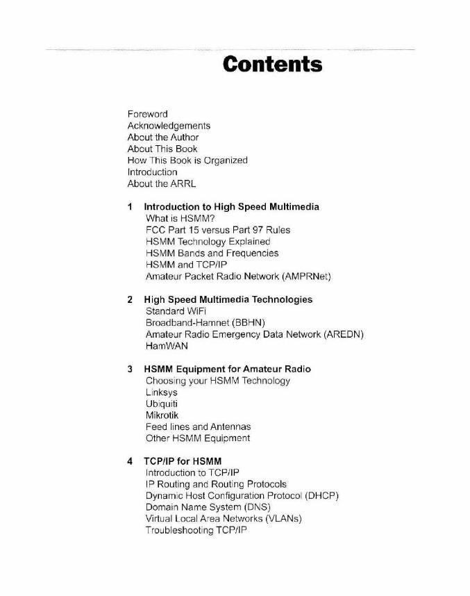
Foreword Acknowledgements About the Author About This Book
Contents
How This Book is Organized Introduction About the ARRL
1 Introduction to High Speed Multimedia What is HSMM? FCC Part 15 versus Part 97 Rules HSMM Technology Explained HSMM Bands and Frequencies HSMM and TCP/ IP Amateur Packet Radio Network (AMPRNet)
2 High Speed Multimedia Technologies Standard WiFi Broadband-Hamnet (BBHN) Amateur Radio Emergency Data Network (AREDN) Ham WAN
3 HSMM Equipment for Amateur Radio Choosing your HSMM Technology Linksys Ubiquiti Mikrotik Feed lines and Antennas Other HSMM Equipment
4 TCP/IP for HSMM Introduction to TCP/IP IP Routing and Routing Protocols Dynamic Host Configuration Protocol (DHCP) Domain Name System (DNS) Virtual Local Area Networks (VLANs) Troubleshooting TCP/IP

5 HSMM Applications Voice over IP (VoIP) Instant Messaging ClearOS ClipBucket Server TeamSpeak Server Internet-based Applications Using Raspberry Pi as an Application Server
6 Security and Filtering Physical Security Network Security Wireless Security Firewalling and Content Filtering for Part 97 Compliance
7 Backup and Redundancy Power Redundancy Virtualization Network Monitoring Redundant Links
8 Deploying HSMM Networks Site Survey and Mapping Tools Configuring and Deploying HSMM
9 The Future of HSMM
Appendix: Glossary
Foreword For many years radio amateurs have been using our bands at 900
MHz and above for a wide variety of modes and activities. In additio n to CW and SSB terrestrial operation, we've had amateur satellite operation at 1.2 and 2.4 GHz. The wide open spaces on these bands provides space for amateur television. including FM and digital ATV. Most recently amateurs have been building high speed multimedia (HSM M) networks on
these bands using commercial off-the-shelf equipment and developi ng the ir own software. Wireless Amateur Radio digita l networks w ith wide area coverage can support many of the functions and services currently available on the Internet.
In this book, author Glen Popiel. KWSGP, introduces HSM M networking, explains the basics of how it works, and describes the vari ous technologies in use today. He goes o n to explain, in detail, how to deploy your own HSMM network along with various applications to put it to work.
The infrastructure supports the capability to exchange voice, data. and full-motion video. Use your imagination and th ink about what you
could do with your very own high speed wireless network. Some examples: create a robust public service and disaster supp011 network, monitor and control webcams, or link repeaters or networks in different areas.
Amateurs have a long history of experimenting with new modes, bands, and methods of wireless communication. HSMM is the next frontie r ~ give it a try 1
David Sumner, KI ZZ
Chief Executive Officer Newington, Connecticut March 20 16

____ ,, ________ .. _ .. _______ --------
Acknowledgements
To my Dad - ~f you hadn't recommended taking electronics class in high school, none c~f this would hove ever come to be. Thank you.
This book never would have happened without the invaluable assistance of Ryan Turner, K0RET Michael Knight. KK4IOH. and the HamWAN Memphis Metro group. Thanks also go out to Jim Kinter, K5KTF, and the Broadband-Hamnet group for allowing me to use mate rials from their website. I would also like to thank my friend , Tim Billingsley, KDSCKP, for leadi ng the way and introducing everyone in the Olive Branch Amateur Radio club to BBHN and mesh networking, for being my sounding board as the concept for this book came to be, and for his amazing skills as my personal grammar coach.
There are so many others who helped make this book happen, and I apologize in advance to anyone I may have omitted. Thanks to the Olive Branch Amateur Radio Club for their suppo11 and encouragement. I would also like to thank ARRL Publications Manager Steve Ford, WB8IMY, my editor, Mark Wilson, KIRO, and the staff at ARRL for allowing me the opportunity to work with them.
And a special thanks to the in trepid pioneers in the wireless networking technologies. Your continuing experimentation and development has opened up a whole new world of digital communications for Amateur Radio. Thank you.
About the Author
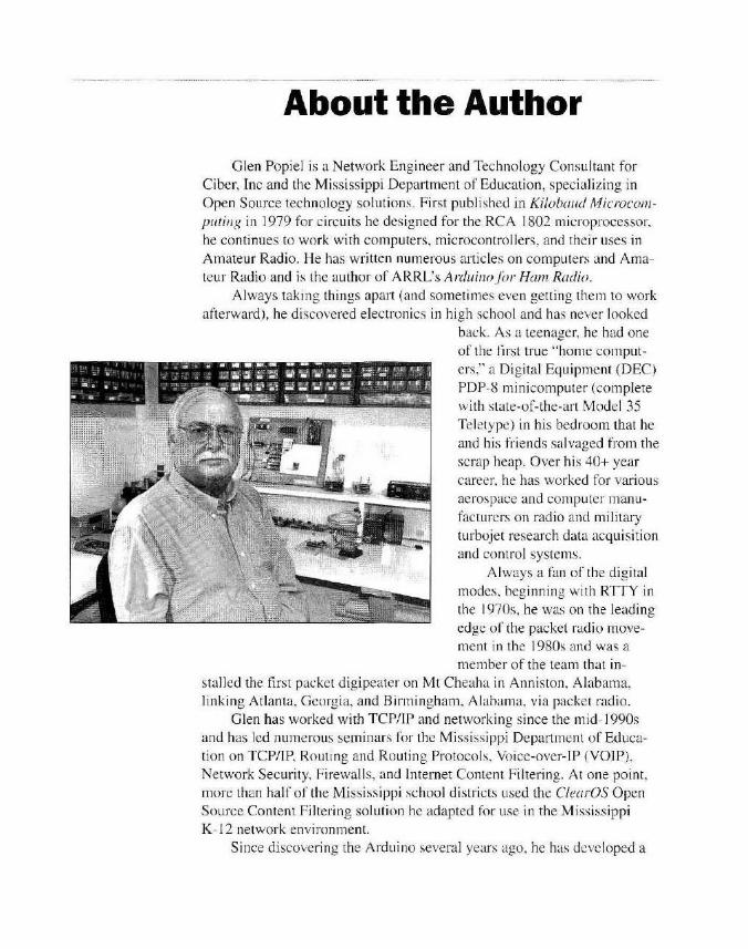
Glen Popiel is a Network Engineer and Technology Consul tant for Ciber, Inc and the Mississippi Department of Education, specializing in Open Source technology solutions. First published in Kilobaud Microco111-puti11g in 1979 for circuits he designed for the RCA 1802 microprocessor. he continues to work with computers, microcontrollers, and their uses in Amateur Radio. He has written numerous articles on computers and Amateur Radio and is the author of ARRL's Arduinoj(1r Ham Radio.
Always taking things apart (and sometimes even getting them to work afterward), he discovered electronics in high school and has never looked
back. As a teenage r. he had one of the first true "home computers," a Digital Equipment (DEC) PDP-8 minicomputer (complete with state-of-the-art Model 35 Teletype) in his bedroom that he and his friends salvaged from the scrap heap. Over his 40+ year career. he has worked for various aerospace and computer manufacturers on radio and military turbojet research data acquisi tion and control systems.
Always a fan of the digital modes, beginning with RTTY in the 1970s, he was on the leading edge of the packet radio move-ment in the 1980s and was a member of the team that in
stalled the firs t packet digipeater on Mt Cheaha in Anniston, Alabama, linking Atlanta, Georgia, and Birmingham. Alabama, via packet radio.
Glen has worked with TCP/IP and networking since the micl- l 990s and has led numerous seminars for the Mississippi Department o f Education on TCP/IP, Routing and Routing Protocols, Voice-over-JP (VOiP), Network Security. Firewalls, and Internet Content Filtering. At one point, more than half o f the Mississippi school distric ts used the CfearOS Open Source Content Fi ltering solution he adapted for use in the Mississippi K- l 2 network environment.
Since discovering the Arduino several years ago, he has developed a

passion for this powerful, inexpensive microcontroller and has given a number of seminars and hamfest forums on the subject of the Arduino and Open Source. He is a member of the Olive Branch Amateur Radio Club (OBARC), QRP Amateur Radio Club International (QRP-ARCI), and the QRP SkunkWerks, a design team of fellow hams and Arduino enthusiasts who have succeeded in getting the JT65 digital mode working natively on the Ten-Tee Rebel, a CW-only (so they thought ) QRP Transceiver.
Glen is also a lormer cat show judge and has exhibited Maine Coon cats all over the country, with the highlight being a Best in Show at Madison Square Garden in 1989. He now lives in Southaven, Mississ ippi, where he continues to create fun and exciting new Arduino proj ects for Amateur Radio with his new Maine Coon editors-in-training, Shadow and Angel.

About this Book
Welcome fellow hams and networking enthusiasts. Radio Amateurs have always been at the cutting edge of technology.
and the exciting area of high speed multimedia (HSMM) data communications is no exception. Using commercial off-the-shelf equipment and developing their own software, groups of hams have created high speed wireless Amateur Radio digital networks with wide area coverage that can support many of the functions and services currently available on the Internet. The possible uses for these high speed data networks in the Amateur Radio community are endless.
With the capability to send real-time video and data files, the public service and disaster support aspects of ham radio are expanded tremendously. HSMM networks can be linked together via the Internet, allowing linking of repeaters and other HSMM networks. In an extremely oversimplified view, HSMM allows hams to create a wireless version of the Internet without (or with) the real Internet. In times of disaster, this capability will doubtlessly prove invaluable to the Amateur Radio operators supp01iing public service agencies and disaster relief efforts. With the ability to link to the real Internet under FCC Part 97 rules, HSMM can be used to provide high-speed Internet access in disaster-stricken areas that have no other way to send email, text messages, video, and other multimedia data to the outside world.
But the uses for HSMM don't end with public service and disaster support. HSMM allows hams to link repeaters using modes such as AllStar. EchoLink, D-Star, and others. Vi11ually any service that works on the regular Internet can be adapted to an Amateur Radio HSMM network. Video conferencing, instant messaging, voice-over-IP (VoIP). network sensors and cameras. remote station control, and many other services can be used on an HSMM network.
High speed multimedia is based on the TCP!TP Internet protocol suite. As such, in order to fully understand how an HSMM network operates, you wi ll need a working knowledge of TCP/IP, IP addressing, subnetting, routing, DNS, and other Internet protocols and services. This book is intended to
be an introduction to HSMM. While it does include sections on TCP!TP fundamentals and basics, space restrictions do not permit an in-depth coverage of TCP/IP and the various services and features available with an HSMM network. While some of the HSMM implementations are vi11ually self-configuring and require very little knowledge of TCP!TP to get started, I do recommend at least becoming familiar with TCP!TP, especially as you begin

deploying the various servers and services that can be used on an HSMM network. Two excellent starting points are TCP/IP for Dummies by Candace Leiden and Marshall Wilensky, ISBN 978-0470450604, and an outstanding free online book, The TCP/IP Guide by Charles M. Kozierok at www.tcpipguide.com.
This book is intended to provide an overview of HSMM networking technologies, help with choosing and deploying your HSMM infrastructure, and ideas for putting your HSMM network to work. For more information, I recommended visiting the websites of" the various HSMM development groups for up-to-date and specific information not provided in this book.
Since HSMM involves multiple users, nodes, and groups, I also recommend finding or starting a local group as you begin to plan and deploy your HSMM network. There is strength and knowledge in numbers, and with all the moving parts in an J-ISMM network a team effort is definitely the way to go.
Every effort has been made to include the current HSMM technologies and infrastructures, but the HSMM world is a constantly evolving landscape as evidenced by the recent inclusion of 900 MHz equipment and software into HSMM network implementations along with the creation of the Amateur Radio Emergency Data Network (AREDN ) development group. It is my hope that this book will provide you with the foundation and information you will need to plan and deploy your own HSMM networks regardless of which direction the future of HSMM in Amateur Radio takes us.
How this Book is Organized
This book is intended to introduce wireless high speed multimedia (HSMM) digital data networking for use in Amateur Radio. Starting with a basic introduction to wireless HSMM technology and the use of HSMM digital data networks under Part 97 of the FCC rules for Amateur Radio, the book progresses into the hardware needed to deploy your own HSMM network and the underlying concepts that fonn the foundation of an HSMM network. This is followed by an introduction to TCP/IP networking and the services you can deploy and provide over an HSMM network. Security and network redundancy are also discussed, followed by information on planning and deploying your own HSMM network.
Chapter 1, Introduction to High Speed Multim edia, provides an introduction to HSMM technology, frequencies, the differences between some of the various HSMM networks, and the differences between FCC Part 15 and Part 97 rules regarding wireless data networks.
Chapter 2, High Speed Multimedia Technologies, describes the various technologies, equipment, frequencies, and concepts used in Amateur Radio HSMM networks.
Chapter 3, HSMM Equipmelllfor Amateur Radio. describes the equipment used in Amateur Radio HSMM networks.
Chapter 4, TCP/IP.for HSMM, provides an introduction lo TCP/IP addressing, subnetting, routing, routing protocols, DHCP. DNS, and other TCP/IP protocols and services used in wireless HSMM networks.
Chapter 5, HSMM Applications, discusses what you can do with a wireless HSMM network, the services and applications that can be used on an HSMM network along with a discussion on how to deploy these services and applications.
Chapter 6, Securitr and Filterin[?. discusses methods and techniques to secure your HSMM network and limit its use to authorized Amateur Radio operators.
Chapter 7, Backup and Redundancy, discusses methods and techniques to improve the availability and redundancy of your HSMM network.
Chapter 8, Deploying HSMM, discusses how to plan and deploy the various HSMM networks currently available for Amateur Radio.
Chapter 9, The Future of HSMM, takes a final look at where HSMM is today and looks at where and what HSMM may become in the future as it relates to Amateur Radio.
Finally, in an Appendix. a Glossary defines many of the terms and acronyms used in this book.

Introduction
Did you know thal there is ham radio life above 1.2 GHz'I !l's not j ust the usual ham activity such as CW. SSB. and FM. but ii is indeed still ham radio. These frequencies have become 1hc home of one of the newest forms of Amateur Radio communications, known as high speed multimedia digital data (HSMM). Hams have always been experimenters and the world of HSMM networking is their latest playground. Using off-the-shelf commercial wireless devices in the 2.4 GHz and 5 GHz spectrums. hams have adapted these devices for use in high speed wireless networks. linking users and nodes together. allowing for 1he high speed transmission of all forms of digital data across wide areas of coverage. HSMM developers have also recently begun exploring the use of HSMM networking in other bands, incl uding 900 MHz, which will allow even wider areas of coverage .
Sometimes generically (and in some cases incorrectly) referred to as ··mesh networking," HSMM provides a platform for computer-to-computer communication using methods and protocols used on the Internet. In a very oversimplified way, HSMM networks can be viewed as a wireless Amateur Radio version of the Tnternel that works with or wi thout connection to the actual Internet. Based on the TCP/IP protocols and services used in the Internet, HSMM can be used to provide a wide am1y of d ig ital data services such as voice over IP (VoIP). video conferencing, file transfer, and j ust about any other service currently available on the Internet. HSMM networks can even be linked together over the Internet. providing an even wider array of services and functionality. Since HSMM networks can be linked lo the Internet, repeater linking services such as AllStar, EchoLink. and others can be used to seamlessly link hams and repeaters all over the \vorld.
While some HSMM networks are indeed based on a mesh topology (hence the term "mesh networking"), the HSMM landscape is ever-changing, with new concepts and networking models being implemented and released all the time. Each networking mode l has its advantages and disadvantages which will be discussed further in this book.
The possibilities for HSMM networking in the public service sector of Amateur Radio are endless. Inexpensive and rapidly deployable portable HSMM networks can be quick.ly set up in times of di saster to provide reliable voice and data services with the ability to send and receive data over the HSMM network and even the Internet, providing a full range of video, voice and other data communication services to areas that might otherwise have none . Public service agencies can be linked together wirelessly over

HSMM networks, providing a vital communication link between these agencies if the Internet, telephone, or other forms of communication are unavailable. HSMM networks can also be used to access, monitor. and control IP-based webcarns and other devices. providing remote viewing and data telemetry.
But an HSMM network is only the vehicle to provide these communication services. Since an HSMM network is TCP/IP based, just as with the Internet. it only provides a path to the various applications and serv ices. lt is these applications and services that form the core of an HSMM network and what makes it such an infinitely useful tool for the communication of virtually any form of high speed digital data.
This book is intended to provide an introduction to HSMM networking, how it works, how to deploy your own HSMM network, and the various applications yo u can use with HSMM networks. Since the techno logy of HSMM is constantly changing, emphasis has been placed on understanding the underlying technologies, TCP/IP protocols and services, and HSMM applications. It is my intent that by focu sing on the fundamentals and application of HSMM networking rather than trying to cover the minute details of each and every indi vidual aspect o f the various HSMM networking that could be quickly out<latcd will provide you with the knowledge and foundation you can use as you derloy your own HSMM networks and applications.
73. Glen Popiel, KWSGP k w5gp@a rrl. net Southhaven, Mississippi February 2016
About the ARRL
The seed for Amateur Radio was planted in the 1890s, when Gug lie lmo Marconi began his experiments in wireless telegraphy. Soon he was joined by dozens. the n hundre ds, of others who were enthus iastic about sending and recei ving messages through the a ir - some with a commercial interest, but others solely out of a love for this new communications medium. The Uni ted States government began licensing Amate ur Radio operators in 19 12.
By 1914, there were thousands of Amateur Radio operators - hams - in the United States . Hiram Percy Maxim . a leading Hartford, Connecticut inventor and industrialis t. saw the need for an organization to unify this fledgling group of radio experime nters. In May 19 14 he founded the American Radio Relay League (ARRL) to meet that need.
ARRL is the national a ssociation for Amateur Radio in the US. Today, w ith approxi mately 170,000 members, ARRL numbers within its ranks the vast majority of active rad io amateurs in the nation and has a proud history of achievement as the standard-beare r in amateur a ffa irs. ARRL's underpinnings as Amateur Radio 's w itness. partner. and forum arc defined by fi ve pillars: Public Service . Advocacy. Educat ion. Technology. and M embership. A RRL is also In ternational Secretariat for the International Amateur Radio Union. which is made up of similar societies in 150 countries around the world.
ARRL's Mission Statement: To advance the art. science, and enjoyment of Amateur Radio.
ARRL's Vision Statement: As the national association for Amateur Radio in the United States, AR RL:
• Supports the awareness and growth of Amateur Radio worldwide; • Advocates for meaningful access to radio spectrum; • Strives for every member lo get involved. gel active. and ge l on the air: • Encourages rad io experime ntat ion and. through its rne mhcrs. advances radio technology and
educat ion; and • Organizes and trains volunteers to serve the ir communities by providing pu blic service and
emergency communications.
At ARRL headquarters in the Hartford. Connecticut suburb o f Newington. the staff helps serve the needs of members. ARRL publishes the monthly journal QST and an interactive digital version of QST, as well as newsletters and many publications covering all aspects of Amateur Radio. !ls headquarters station, WI AW, transmits bulletins of inte res t to radio amateurs and Morse code practice sess ions. ARRL al so coordi nate s an extensive field organization, which includes volunteers who provide technical in formation and other support services for radio amateurs as well as communications for public service activ ities. In add it ion, ARRL represents US radio amate urs to the Federa l Communications Commission and other government agencies in the US and abroad.
Membership in ARRL means much more than receiving QST each month. In addition to the services already de scribed, ARRL offe rs membe rship se rvices on a personal level , suc h as the Technical In formation Service. where members can get answers - by phone. e -mail, or the ARRL websi te - lo al l their techni cal and operating questions.

A bona fide interest in Amateur Radio is the only essential quali fica tion of membershi p: an Amate ur Radio license is not a prerequisi te, although full voting membership is granted only to licensed radio amateurs in the US. Full ARRL membership gives you a voice in how the affairs of the organization are governed. ARRL policy is set by a Board of Directors (one from each of IS Divisions). Each year, one-third of the ARRL Board of Directors stands for election by the full members they represent. The day-to-day operation of ARRL HQ is managed by a Chief Executive Officer and his/ her staff.
Join ARRL Today! No matter what aspect of Amateur Radio attracts you, ARRL membership is relevant and important. There would be no Amateur Radio as we know it today were it not for ARRL. We would be happy to welcome you as a membe r! Join online at www.arrl.org/join. For more information about ARRL and answers to any questions you may have about Amateur Radio, write or call:
ARRL - The national association for Amateur Radio~ 225 Main Street Newington CT 06 111-1494 Tel: 860-594-0200 FAX: 860-594-0259 e-mai l: hq @arrl.org www.arrl.org
Prospective new radio amateurs call (toll-free): 800-32-NEW HAM (800-326-3942)
You can also contact ARRL via e-mail at [email protected] or check out the ARRL website at www.arrl.org

Chapter 1
Introduction to High Speed Multimedia
Hidden in the fine print at the bottom of the ARRL's US Amateur Radio bands chm·t, you can see that hams have frequency allocations in the 900 MHz (33 cm), 1.2 GHz (23 cm), 2.4 GHz ( 13 cm), 3.4 GHz (9 cm), and 5 GHz (5 cm) bands. Coincidentally, some of these bands overlap with the standard WiFi frequencies used in wireless routers and access points found in many home computer networks. WiFi ho tspots. and the like. Hams have adapted commercial off-the-shelf wireless de,·ices for Amateur Radio use and are creating thei r own wireless networks.
Operating under Part 97 of the FCC rules for the Amateur Radio Service, hams can use these devices for Amateur Radio purposes with higher power leve ls and higher gain antennas, thus enabling these networks to encompass a far wider area than would be possible with a standard wireless access point. At most. a ll you need to do is install a simple firmware upgrade to certain standard WiFi devices. and in the case of the Ham WAN technology descri bed later. you don't need to do any firm ware changes at all.
Using this technology, hams have developed and deployed complete high speed wireless networks. These networks can also be linked to the Internet, allowing hams to have the best of both worlds as long as the network usage remains FCC Part 97 compliant. We' 11 cover how Part 97 applies to Amateur Radio High Speed Multimedia (HSMM) networks in a bit. In a nutshell , as long as you're not using an Amateur Radio HSMM network to make money or run a business or other commercial use, and don ' t encrypt your data (more on that later too). you're pretty much good to go.
Introduction to High Speed Multimedia 1.1

What is High Speed Multimedia?
1.2 Chapter 1
So, what exactly is High Speed Multimedia? When you watch a video or listen to music over the Internet. that's multimedia. When you read your emai l and there's an image or video attached to the email, that 's also mul-1imedia. Whe n you browse a website that has 1ext, images. and audio, tha1's multimedia. When you play computer games online, that too is multimedia. Al the very bas ic level, multimedia is just what it sounds like - multiple forms of media (data) such as vo ice, video. data, and text that compulers can extracl from the data slream and present in a varie ty of ways. With your home computer. you can access a wide variety of multimedi a content with the simple clic k of a mouse and a web browser. For this data to be used in real-time, the information must be received at a speed fast enough for your computer to reassemble the data stream into a conlinuous, non-inleITupted fashion so that the video, aud io, or both, doesn' t stop and start. stutter, or become unu sable as it was intended to be used.
Prior to 1hc advent of Amateur Radio HSMM networks, hams were severe ly limited in !he speed at which !hey could send and receive digital data over the air. Packet radio at 1200 or 9600 baud was about as good as you could hope for. Sending a large, high-resolut ion image or file took forever, and you could forget about tryi ng to watch a video of any sort . Even at 128 kilobits per second (kb/s ), Di gital Data mode (DD) on D-STAR and similar dig ital modes aren' t robusl enough to handle any serious multimed ia data. The physical and regulatory data rate restrictions for the bands and modes used below 902 MHz just don' t a llow for today"s modern multimedia content. Current Amateur Radio HSMM networks can transfer data at speeds up 54 megabits per second (Mbps). and there is no regulatory data speed li mit at frequencies above 902 MHz. As the technology advances, we can expect to see even higher data rales available with HSMM networks.
All of th is is accomplished wi1h inexpensive commercial off-the shelf wireless equipment such as certain models of the Linksys WRT54G, Ubiqui ti M series. and MikroTik RouterBOARD Metal wire less routers to name a few. Convert ing these devices for use in an Amateur Radio HSMM network involves a simple change of the device fi rmware - no soldering needed. In the case of the MikroTi k wireless router used in HamWAN networks, you don' t even need to change the fi rmware.
At the time !hi s book was writlen in the fall of20J5 , the Linksys WRT54G routers were available on eBay for $15. the Ubiquiti Rocket M2 was selling for $75 on eBay, and the MikroTik Metal was available new for $85. High-gain parabolic mesh antennas were selling new for around $ 100. As you can see, the basic cost for an HS MM node in your shack is

not all that expensive. The HSMM firmware for additional dev ices is constantly being developed, so by the time you read this, there could be many more off-the-shelf devices that have been adapted for use with an Amateur Radio HSMM network.
Part 15 versus Part 97 Equipment and Operation All of the devices cunently used in Amateur Radio HSMM networks
are covered by the FCC under Part 15 rules governing unlicensed radio frequency devices. Typically, this means they are intended for very short ranges and are limited to l W of output power. A modification to the FCC rules in 2004 allowed commercial unlicensed WiFi devices to be used wi th higher gain antennas under very specific guidelines and reduced power output, allowing higher equivalent isotropic radiated power (EIRP) levels, but in general. the El RP of these devices is li mited to 4 W. Reduced transmitter power does allow for higher levels of EIRP achieved by using a higher gain antenna, but the manufacturers must certify their devices with these higher gain antennas.
Now, here's where being a ham can be a benefit when it comes to the WiFi frequencies and devices. Under FCC Part 97 rules for Amateur Radio, hams are granted band all ocations in porti ons of the Wi Fi bands with fewer restrictions and much higher power levels. The standard Part 15 commercial WiFi devices can be repurposcd by hams and used under Part 97. To operate a Part I 5 device under Part 97, all you have to <lo is connect everything up and operate under the standard Amateur Radio Part 97 rules - the usual things like identifying every 10 minutes, no pecuniary interest, no obscenity or pornography. and so on. It's as simple as that.
On certai n portions of the WiFi hands you can even run up to 1.5 kW (PEP) of power. Now. before you run out and get that ampli fier (assuming you can afford one). remember that the WiFi bands are at microwave frequencies. Your average home microwave oven puts out about I 000 W and look what it can do to food. Before working with microwave gear, it 's prudent to review the ARRL's RF safety web page at www.arrl.org/rfexposure.
High powered microwave ampl ifiers can get expensive in a real hurry. Radio transmissions at the WiFi frequencies arc mainly line-of-sight, and as such, using additional power to that extreme really won' t buy you a whole lot. And, don't forget the part of the rules that says we should use the minimum power needed to establish communication.
Fortunately, you won't need a whole lot of power to build out a usable HSMM network . The majority of depl oyments are done with standard WiFi devices and high gain directional antennas. Communication distances of I 0 to 15 miles are easily achievable, and based on terrain, even
Introduction to High Speed Multimedia 1.3

longer distances are possible. With just I 00 mW of power, a WiFi link of 237 miles between two mountains in Venezuela was achieved using standard WiFi equipment, but your mileage will most definitely vary. It all depends on your terrain, path obstructions. and your station configuration.
The on ly modification we need to do to the equipment is to change the operating system of the device, also known as fi1111ware. to run one of the standard Amateur Radio HSMM firm ware packages. You don't even have to do that. You can just run standard IEEE 802.11 WiFi. but due to the rules against encryption, you run the risk of unlicensed users on your Amateur Radio network. To avoid that, you will want co run one of the Amateur Radio HSMM firmware packages on your HSMM devices. Since the Ham WAN network does not use modifi ed lirmware, other methods have been devised to ensure that only licensed hams can access the network.
HSMM Technologies Explained There arc a number or HSMM technologies currently being developed
for Amateur Radio. As of the fall of 20 15. Broadband-Hamnet (BBHN ). Amateur Rad io Emergency Data Network (AREDN). and Ham WAN are the p1imary technologies being used in Amateur Radio HSMM networks. Since it is a relat ively new area of development, there are many other technologies being researched and deployed. but the three listed above appear to be the most popular at the nm-ent time. With the HSMM landscape as it
re lates to Amateur Radio in a near-constant state of flux. this book will focus more on the technology, fundamentals. and applications for HS MM. Regardless of which technologies end up being widely deployed, by understanding how it all works. you 'II have a much better understanding of how to deploy and use an HSMM network.
There are two basic forms of HSMM network topology currently being used in Amateur Radio HSMM networks. The BBHN and AREDN networks use what is known as a "mesh"
Peer to Peer Mesh Network ARRL 1411 torology (Figure 1.1). More commonly known as "peer-topeer mesh" or "ad-hoc" net-Figure 1.1 - Diagram of a Peer to Peer Mesh Network.
1 .4 Chapter 1

Node 1
works, all of the nodes in the network can communicate with all the other nodes in the network, e ither directly or by relaying the data through intermediary nodes. similar to the way it is done with packet radio. The data, a lso known as "packets," is automatical ly routed to where it needs to go.
As more devices are added to the network. the mesh net work will automat ically discover the new nodes and modify the data path f'o r the packets. Similarly. if a node goes offline, that path will be "dropped'" and the packets will be automatically rerouted accordingly. T his is one of the advantages of the mesh topology as it is being used in Amateur Radio HSMM networks. Since it is a self-discoveri ng. self-ad vertis ing . self-healing fonn of network. as long as there is a path be tween the sou rce and destination nodes. the data w ill get there.
The downside is that your data is at the mercy of the time it takes to get from Point A to Point B. and there is a greater chance for packet loss (and the retransmi ssion time for the lost packet ). As with packet radio. the higher the user dens ity. the lower the individual throughput w ill be. Since all the devices operate on the same channel, if two nodes that can't hear each other are sending to a third node that can hear both. the data "'collides" and wil l have to be retransmitted. This is known as the " hidden node"' issue and it can have an impact on overall data throughput.
One major advantage of the mesh topology as implemented by the BBHN and AR EDN techno logies is the dynamic nature of the network
structure. As new nodes come o nl ine, or drop ofnine. the network automatically re-ro utes the data according ly. This is ideally suited for portab le or emergency
Main Node 3 scenarios where a data network needs to be set up quickly that can rapidly adapt to chang ing conditions in the fi eld . Due to the low power demands o r the equipment. battery, solar, or other alternative means of power can be used to quickly depl oy an HSMM net\vork in the case o f a portable
Site
Node 2
Hub and Spoke Network ARRL 1412
operation for a publ ic service event or a disaster.
T he Ham WAN network uses
Figure 1.2 - Diagram of a Hub and Spoke Network.
what is known as " hub and spoke' ' or "star" topology (F igure 1.2 ). In this topology, all
Introduction to High Speed Multimedia 1.5

nodes communicate d irectly with a central site, known as a '"cell site" in Ham WAN tenninology. The individual nodes cannot communicate directly with each other, nor can they act as relay points for nodes that can ' t reach a cell site. This means chat every user node must be able to communicate with a cell site. The cell sites communicate between themselves to rel ay the traffic between the various nodes.
A typical Ham WAN cell site has three antennas with a 120 degree arc of coverage each, allowing for a higher simultaneous user density by dividing the load into three zones of coverage. The big advantage of this is a much higher overall data throughput with less chance of data coll isions. Since the nodes communicate directly with the cell site, there is also less chance of data loss si nee you 're dealing wi th a single "hop' ' to the cell site instead of your data possibly being re layed through multiple nodes. The downside of this network topology is that it creates a "sing le po int of fai lure." If the cell site should go down for any reason. all users o f that site are offline until the cell si te comes back online. It could also impact data travelling between other cell sites if the cell site that goes down is a re lay point between other cell sites.
Nei ther topology is better than the other. Each has its advantages and di sadvantages, and how you plan to depl oy and utilize your HSMM network will have a lot to do with which technology and network topology you choose to deploy.
HSMM Frequencies Currently, the majority of HSMM activi ty is occurring in the 2.4 and
5 GHz bands. This is primarily due to the adaptation of commerc ial offthe-shelf devices for Amateur Radio purposes. Several of the HSMM technologies are also branching out into the 900 MHz (33 cm) and 3.4 GHz (9 cm) bands.
Figu re 1.3 shows frequency allocations in the 2.4 GHz band. You will
13 cm Amateur Band 2.390 - 2.450 GHz
I -2
I -1
I 0
I 1
I 2
I 3
I 4
I 5
I 6
I 2.397 GHz 2.402GHz 2.407 GHz 2.4 12 GHz 2.417 GHz 2.422 GHz 2.427 GHz 2.432 GHz 2.437 GHz
Channel frequencies listed are for the center of the channel
Part 97 2.390 - 2.417 GHz I Part 97 and Part 15
13 cm (2.4 GHz) B and Chart ARRL1413
Figure 1.3 - 2.4 GHz (13 cm) frequencies.
1 .6 Chapter 1

I
notice that in addition to standard WiFi channels I thru 6 available for Part 97 Amateur Radio use, there are three additional channels below Channel 1. Defined as Channel 0, - 1, and -2, they are available for amateur use as well. By installing the "slide-band modification" on Lhe Linksys WRT54G wireless router as shown on the BBHN website, which involves making hardware modifications and changing the crystal frequency in the Linksys devices, these channels are accessible. However. these frequencies are also used for Amateur Radio weak-signal work and satellite links. and the potential for interference exists. It would also require Lhat all devices in the network have the modification installed to place them all on the same channel. Since this would require all users to modify their equipment, it's not recommended.
By default, a 2.4 G Hz Amateur Radio HSMM network is configured to run on WiFi Channel 1. S ince the 2.4 GHz spectrum is shared wi th the standard FCC Part 15 devices. there can be a significant number of unwanted signals from these users. This interference is known as the " noise floor." For thi s reason. a number of HSMM implementations are movi ng up to the quieter, less crowded 5 GHz spectrum, where standard Part 97-only channels are avai lable for amateur use, e liminating the interference from Part 15 devices.
While the Linksys WRT54G series o f wi reless routers docs not support the 5 GHz band. the Ubiquiti and MikroTik support HSMM for ham use in the 5 GHz band. Certain Ubiqui ti models can run the BBHN and AREDN firmware utili zing a mesh topology, w hile the MikroTik rou ters are recommended for use in the Ham WAN star topology. As the chart in Figure 1.4 shows, standard WiFi channels 132 - 140 and 169 - 180 do not a llow Part 15 devices, so amateurs operating under Part 97 rules have a much quieter portion of the band to deploy their networks w ithout worry of interference from the Part 15 devices.
US Frequency Allocations
5 cm Amateur Band 5.650 - 5.925 GHz
Channels 132- 140 I Channels 149-165 I Channels 169-180 I
Part 97 I Part 97 and Part 15 I Part 97
5 cm (5 GHz) Band Chart ARRL1414
Figure 1.4 - 5 GHz (5 cm) frequency allocations.
Introduction to High Speed Multimedia 1.7
The band allocations shown are for the United States. Some additional frequencies in the 2.4 and 5 GHz bands are permjtted internationally. Please consult the allowed bands and frequencies for your specific country if you plan to deploy an HSMM network using WiFi channels other than those recommended.
HSMM and TCP/IP
1.8 Chapter 1
This book is intended to be an introduction to the world of High Speed Multimedia in Amateur Radio. As such, we will focus on understanding and deploying an HSMM network and how co implement the various applications and services you may want available on your network. For a much more in-depth technical look at HSMM in general, I recommend reading the free on line hook, "Wireless Networking in the Developing World," available at www.wndw.net. While it does no t contain a lot of ham-specific information, it does provide an in-depth discussion of the technologies used in J-ISMM networks in general.
S ince an HSMM network is p1imarily built using repurposed commercial equipment. the networking technology using in an Amateur Radio HSMM network is based on the Transmission Control Protocol/ lntemec Protocol (TCP/JP), or IP for short. IP stands for Internet Protocol and it is one of the most common networking protocols in use today.
IP is how your home computers move data to and from the Internet. Computers. routers, and other network devices all '·speak' ' TCP/IP and use the information contained in an IP data packet to route the data to its intended destination automaticall y.
Can you imagine how difficult it would be if you were sending someone a letter, and instead of simply dropping it o ff at the post office, you had to put your letter in a dozen o r more envelopes, with each physical ·'hop" requi1ing a separate envelope? Fortunately. you don' t have to do that. Your local post office handles all of the steps needed to get your le tter across the country without you even knowing how or what they use to get it there. It 's the same with IP. You simply g ive the data packet the "destination address" and off it goes into the Internet where it eventually gets delivered to where you sent it without you needing to know any of the intermediate routing step that takes place to gee it there.
Since an Amateur Radio HSMM network is independent from the lntemet. it is up to you to put a ll of the infrastructure in place to handle the routing of this data. Fortunately, a lot of this is handled automatically within the network and all you need to do is some basic setup. However, a good understanding of how TCP/IP works and how to set it up is important for you to properl y set up your HSMM network. We ' ll cover TCP/IP in much more detai l in Chapter 4.

The Amateur Packet Radio Network (AMPRnet)
Final Thoughts
In the late 1970s, long before lhe creation of the public Inlerner as we know it today, Dr Hank Magnuski , KA6M, had the incredible foresight to register an ent ire Class A IP address range (16.7 million IP addresses) for Amateur Radio use. The entire IP address block of 44.0.0.0/8 is allocated for ham use. and any licensed ham can request a sub-block of this address range for free through AMPRnel. Wi th the Internet now o ut of IPv4 address allocatio ns, the AMPRnet block of addresses is very valuable real estate indeed. (IPv4, Internet Protocol version 4, is used to route most Internet traffic today.) This b lock o l' publi c IP addresses allows hams to access and link their ne tworks directly w ith the public Internet and to other Amateur Radio networks. For mo re information on requesti ng and receiving a block of public IP addresses for your network. please visi t the AMPRner website at www.ampr.org.
One final thing to remember. HSMM is a techno logy. not an application. When you bui ld an HSMM network. all you are doing is bui lding an infrastructure for the data to travel over. Think of it li ke a road or highway. This is why the Internet is o ften referred to as ·'The Information Superhighway.''
To travel anywhere effic iently, you need roads. Think of the vehicles o n the road as your app lications. It doesn ' t really matter if it ' s a car, motorcycle. bu s. or what have you, but without roads, getting around is d ifficult at best. Without the vehicles. a road just sits there and doesn' t do a whole lot. You need both. It's the same way with HSMM . You need the infrastructure to he lp you move your data between places, but it is what you do with your ne twork that turns it into a very powerful tool.
The most often asked quest ion regarding HSMM is "What do I do with all th is once I have it running?" This is where the applications come in. Applications are the vehicles that use the roads you build. Because your network uses the TCP/IP protocol. pretty much anything you can do with the Internet. you can do with your HSMM network . You can set up web servers and voice-over-IP systems (VoIP, IP Lelephones ), transfer files. chat, and j ust about anything else that yo u would do with your home computer attached to the Internet. T he mai n difference between your HSMM network and the Internet is that it is up to you to deploy the various applications you want to use o n your ne twork.
Introduction to High Speed Multimedia 1.9

References
1.1 O Chapter 1
www.ampr.org www.aredn.org www.arrl.org/graphical-frequency-allocations www.broadband-hamnet.org www.HamWAN.org www.memHamWAN.org www.wikipedia.org www.wndw.net
Chapter 2
High Speed Multimedia Technologies
No discussion on Amateur Radio HSMM technologies would be complete without first discussing the standard FCC Part 15 consumerbased WiFi technologies. Since hams have ptivileges within the standard WiFi bands, there is nothjng preventing hams from taking a standard FCC Part 15 wireless device (unmodified) and operating it under FCC Part 97 rules for Amateur Radio purposes. Keep in mind, that to be Part 97 compliant, you have to identify your station every 10 minutes, use no encryption, use your network for no business purposes, and follow the other Part 97 rules.
While technically you can use the standard WEP and WPA wireless encryption methods, you have to publicly post the encryption keys. So, for all intents, using WEP or WPA encryption is pretty much use less. The reason you have to publicly post your wireless key is to maintain compliance with the Part 97 rules that prohibit using encryption to obscure your transmissions. The problem here is that without viable encryption or other security methods, anyone can connect to your network and use it.
You would have to use a method such as MAC address filtering to allow only authorized users on your network. (See the sidebar, MAC Addresses - What Are They?) MAC address filtering allows you to control who accesses your network, based on their wireless device 's MAC address. The issue here is that MAC addresses are easily forged (also known as spoofing) by hackers. There are other security methods you can implement to prevent unauthorized users, but since all of your data can be intercepted by anyone, it would only be a matter of time before some non-ham hacker got onto your network.
High Speed Multimedia Technologies I 2.1
Under Part 97 rules, you can use a standard Part 15 wireless device with higher power and higher gain antennas, as long as you remain Part 97 compliant. However, depending on which modulation method your wireless device uses, the ru les get a bi t quirky to say the least.
The IEEE 802.11 Standard There are several modulation methods used in standard Part 15 Wi Fi
dev ices. all based on the IEEE 802.1 1 standard. The most common ones are 802 .1 la, 802.1 I b. 802. 1 lg, 802. 11 n. and 802.11 ac.
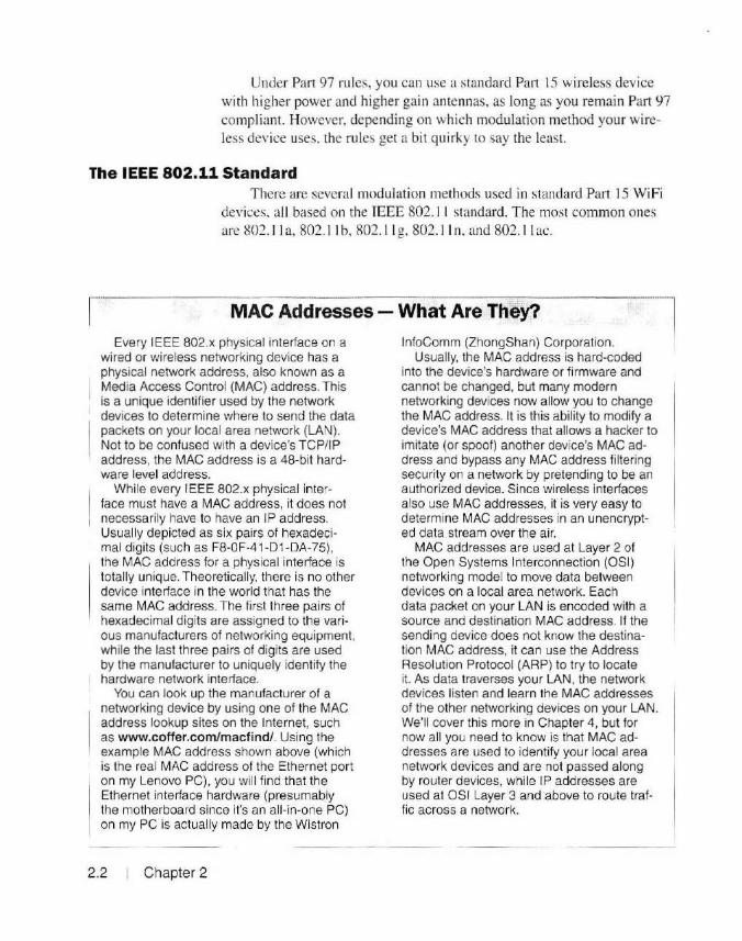
MAC Addresses - What Are They?
Every IEEE 802.x physical interface on a wired or wireless networking device has a physical network address, also known as a Media Access Control (MAC} address. This is a unique identifier used by the network devices to determine where to send the data packets on your local area network (LAN). Not to be confused with a device's TCP/IP address, the MAC address is a 48-bit hardware level address.
Whi le every IEEE 802.x physical interface must have a MAC address, it does not
1 necessarily have to have an IP address. Usually depicted as six pairs of hexadecimal digits (such as F8-0F-41-D 1-DA-75), the MAC address for a physical interface is totally unique. Theoretical ly, there is no other device interface in the world that has the same MAC address. The first three pairs of hexadecimal digits are assigned to the various manufacturers of networking equipment, while the last three pairs of digits are used by the manufacturer to uniquely identify the hardware network interface.
You can look up the manufacturer of a networking device by using one of the MAC address lookup sites on the Internet, such as www.coffer.com/macfind/. Using the example MAC address shown above (which is the real MAC address of the Ethernet port on my Lenovo PC), you wil l find that the Ethernet interface hardware (presumably the motherboard since it's an all-in-one PC) on my PC is actually made by the Wistron
2.2 Chapter 2
lnfoComm (ZhongShan) Corporation. Usually, the MAC address is hard-coded
into the device's hardware or firmware and cannot be changed, but many modern networking devices now allow you to change the MAC address. It is this ability to modify a device's MAC address that allows a hacker to imitate (or spoof) another device's MAC address and bypass any MAC address filtering security on a network by pretending to be an authorized device. Since wireless interfaces also use MAC addresses, it is very easy to determine MAC addresses in an unencrypted data stream over the air.
MAC addresses are used at Layer 2 of the Open Systems Interconnection (OSI) networking model to move data between devices on a local area network. Each data packet on your LAN is encoded with a source and destination MAC address. If the sending device does not know the destination MAC address, it can use the Address Resolution Protocol (ARP) to try to locate it. As data traverses your LAN, the network devices listen and learn the MAC addresses of the other networking devices on your LAN. We'll cover this more in Chapter 4, but for now all you need to know is that MAC addresses are used to identify your local area network devices and are not passed along by router devices, while IP addresses are used at OSI Layer 3 and above to route traffic across a network.

IEEE 802.11b IEEE 802.11 b was used in the first consumer wire less access points
and routers. IEEE 802.11 b offers speeds up to 11 megabits per second (Mbps). Using Adaptive Rate Selection , the speed can automatically be adjusted down to 5.5 Mbps. 2 Mbps, or I Mbps based on the quality of the data link. IEEE 802. 11 b uses eight overlapping channels in the 2.4 GHz ( 13 cm ) WiFi band. Since the US 2.4 G Hz WiFi band uses channels I through 11, you can sec how devices can interfere with devices on adjacent channels due to the overlapping channe ls. IEEE 802. 11 b uses the direct sequence sprcau spectrum (DSSS) modulation method. This modulation method is defined as a spread spectrum transmission. and as such is subject to the FCC Part 97 rules regarding spread spectrum transm issions. Amateur transmissions using IEEE 802. 1 lb are limited to a maximum power output of just I 0 W PEP.
IEEE 802.11g IEEE 802. 1 lg followed 802.l l b in consumer WiFi devices. IEEE
802. 11 g offers speeds up to 54 Mbps, using the same eight overlapping channels in the 2.4 GHz WiFi band. IEEE 802.1 1 g is backward-compatible wi th 802.1 1 b. and also implements Adaptive Rate Selection, allowing reduction of data speed to 48. 36, 24, 18, 12, 9 , and 6 Mbps in addition to the 802 .11 b speeds based on link quality.
The FCC rules regarding IEEE 802. 1 I g operations in the WiFi bands under Part 97 are different from those for 802. I lb. IEEE 802. l l g does not use the DSSS modul ation method used in 802. l I b. In stead, 802. l l g uses the orthogonal frequency division multiplex ing (OFDM ) modulation method. In 200 I, an FCC rules clarification stated that OFDM is not a spread spectrum transmission , and therefore it is not subject to the FCC Part 97 restrictions regarding spread spectrum transmissions. Thi s means that the maximum allowable output power for IEEE 802.1 Jg is the usual 1500 W PEP. Since 802.1 I g is backward-compatible with 802. 11 b, you will need to disable the 802.11 b functionality in these devices to maintain Part 97 compliance when using higher power levels. Also remember, you are working with microwave frequencies. similar to the frequencies used in microwave ovens. Be very carefu l when using higher power microwave transmi ssion equ ipment and antennas.
IEEE 802.11n Next for the consumer WiFi devices is IEEE 802.11 n. Backward
compatible with 802.11 big devices, IEEE 802. 11 n uses multip le input multiple output (MIMO) antenna technology to offer data rates from 54 Mbps up to 600 Mbps. IEEE 802. l l n uses the same eight overlapping
High Speed Multimedia Technologies 2.3
2.4 I Chapter 2
channels in the 2.4 G Hz WiFi band. but has the capabil ity of using mult iple channels simultaneously. However. when used under Amateur Radio Part 97 rules, using multiple channels can cause you to operate outside of the Amateur Radio portion of the 2.4 G Hz band, so care must be used when selecting the 802. 11 n operati ng mode. IEEE 802.1 In can also be used in the quieter 5 G Hz band, where the advantages of multiple channels and wider bandwidths can be used more effectively. IEEE 802. 1 In uses the OFDM modulation method and is not limited by the Part 97 ru les for spread spectrum transmi ssions. As with IEEE 802.1 lg. maximu m power output is 1500 W PEP.
IEEE 802.11a In order to take advantage of the q ui eter 5 GHz WiFi band, device
manufacturers implemented the IEEE 802. 11 a standard . IEEE 802.1 1 a uses twelve non-overlapping channels in the 5 GHz band instead of the e ight overlapping channe ls used by IEEE 802. 11 b/g/n in the 2.4 G Hz band. IEEE 802. 1 I a o ffers data speeds up to 54 Mbps, with the same Adaptive Rate Selection features of 802.1 1 g. IEEE 802. 1 l a also uses the OFDM modulation method, allowing amateurs to use a maximum power output of 1500 W PEP.
IEEE 802.11ac IEEE 802. 1 I ac is a recently adopted IEEE standard for the 5 GHz
WiFi band . Utilizing the same MIMO technology as in IEEE 802. 11 n, and using wider channe l bandwidths, IEEE 802. 11 ac has an expected throughput of at least I g igabit per second (Gbps). IEEE 802. l lac also uses the OFDM modulation method, a llowing amateurs to use a maximu m power output of I 500 W PEP.
Security in Amateur Radio Networks There is a downside 10 using standard WiFi technology in Amateur
Radio HSMM nerworks. Since hams are not permitted under FCC Pa11 97 ru les to use secure encryption methods in their transmissions, o ther security methods must be devised when using standard WiFi devices on Amateur Radio HSMM networks. Under Part 97 rules, Amateur Radio transmissions are unencrypted (or WEP/WPA with the keys publicized), and therefore are for all inrents in clear-texr over publicly accessible WiFi frequencies. A hacker could easily access your Amateur Radio HSMM network using their standard Pai1 I 5 wireless device and wreak havoc on your HSMM network.
While there are methods you can implement to reduce the security risk from hackers. these methods are often easi ly defeated by a determined
hacker. It also fa ll s to you maintain FCC Part 97 ru les compliance for things such as identification or not allowing your network to be used for business purposes . As a solution to this dilemma, several Amateur Radio development groups have created their own ham-specific network technologies. These technologies address the Part 97 rules and network security issues encountered when using standard WiFi devices in Amateur Radio HSMM networks.
Amateur Radio HSMM Network Technologies Currently, three primary technolog ies are used to implement Amateur
Radio HSMM networks. Broadband-Hamnet (BBHN) and Amateur Radio Emergency Data Network (A REDN) technologies are used to create a peer-to-peer mesh topology. while Ham WAN is used to implement a star topology. The BBH and AREDN technologies use the 802. 11 g modulation method, while Ham WAN uses the 802. l ln-based MikroTik Nv2 modulation method. Both are TCP/IP-based, and you can provide the same applications and services regardless of which networking technology you choose to implemen t. Both also provide a means of connecting your HSMM network to the public Internet, allowing you to interconnect with other Amateur Radio HSMM networks via the Internet and build out a very versatile and functional HSMM network.
Broadband-Hamnet (BBHN) 01iginally known as HSMM-Mesh. Broadband-Hamnet uses inex
pensive, commercial off-the-shelf Linksys and Ubiquiti wireless rou ters. With a simple ti rm ware installation to replace the original router operating fi rmware, it becomes a fully functional node using the peer-to-peer mesh topology. Although it typically uses the standard WiFi frequencies. the BBHN implementation will only communicate with other devices using the same version of BBHN firmware. Whi le standard commercial WiFi devices such as smartphones, tablets, wi re less computer workstations, and so on can see your BBHN network, they wi ll not be able to con nect to or access it.
The BBHN firmware supports certain models o f the Linksys WRT54G series of wire less routers (Figure 2.1) as well as some models of the Ubiquiti wireless routers such as the one shown in Figure 2.2. A complete li st of the currently supported devices is available at www. broadband-hamnet.org. We'll cover installing the firmware and configuring your equipment for BBHN in Chapter 8.
In a BBHN network. every node name (usually your call sign) is adve1tised throughout the network using the Domain Name System (DNS), meaning that you don ' t need to know the IP address of a node to commu-
High Speed Multimedia Technologies I 2.5

. ~/
-~----~--
Figure 2.1 -The Linksys WRTG54 Wireless Router used in the Broadband-Hamnet HSMM network.
2.6 Chapter 2
Figure 2.2 - The Ubiquiti Wireless Router used In Broadband-Hamnet and AREDN HSMM networks.
nicate with it - just its name. Each node also sends out beacon packets containing your call sign to maintai n compli ance with FCC Part 97 rules requ iring identi fication. We' ll ta lk more about DNS in Chapter 4.
A BBHN node is self-discovering, sel f- configuring, self-advertising, and fault tolerant. When you bring your BBHN node online. it wi ll search for other nodes and attempt to form a link with them automatically. At the same time. it will advert ise its presence. along with any applications and services you have configured it to announce. to every other node in the network.
The link between the nodes is formed automatically, with each node accessible by its name or IP address. When usi ng a Linksys WRT54G as a BBHN node, the LAN (local area network) ports on the router are available for your use to connect computers. servers, IP phones, and other IP-based devices. By default, the BBHN router provides Dynamic Host Configuration Protocol (DHCP) through the LAN ports. thereby allowing your computer to automatically be assigned the proper IP address. IP gateway. and DNS server (usually the WRT54G itself) for your node. Each node in the network has a unique range of IP addresses, allowing you to communicate directly with every dev ice in the mesh network . Any node
can be used to provide an application or service, such as a web server, voice-over-IP (VoIP) telephony, and just about any other application or service you can access on the regular Internet.
The LAN side of a BBHN node can be configured to directly support I. 5. or l 3 locally attached devices (hosts). If you need more physical LAN ports than the four provided by the WTG54G or the single LAN port on the Ubiquiti devices, you can attach one of the LAN po1ts to a switch or even a standard WiFi access point, allowing you to increase the number of devices attached to your BB HN node.
When using a standard WiFi access point to access your network, you have to be careful to ensure that no unauthorized users can connect to your access point. Since you can use standard Part 15 devices for your local WiFi access point. you can use wireless encryption and other securi ty methods allowed under Part 15 to secure your local net work.
The BBHN node also supports NAT (network address translation) on the LAN ports. Don't worry if you don't know what NAT, DHCP, and some of these other terms are - we· 11 cover those in depth in Chapter 4. Using NAT allows you to use a wider range of TP addresses on the LAN side of your node. but there are special considerations when using NAT with applications such as Voice-over-IP. Unless you have a good understanding of TP and NAT. it's best to stick with the default setting of 5-host direct.
A BBHN node uses the Optimi zed Link State Routing Protocol (OLSR) to discover and maintain a routing table for all or the nodes in your BBHN network. A routing table is simply a list of IP infom1ation that is maintained internally in each node by the router firmware ·s routing protocol. These routing tables are used by a node to determine the best data path to another node. As BBHN nodes are added or removed, OLSR will keep track and update the routing table information for all of the nodes in the network. Thi s is a ll handled automatically for you as part of the selfdiscovering, self-healing. self-advertising fault-tolerant features of a BBHN network. We 'l l cover routing protocols in Chapter 4. but for now, all you really need to know is that a BBHN network will automatically detennine the best path to send your data for you.
The WAN (wide area network) port on a Linksys WRT54G router in a BBHN network can be used to link your node to the regular Internet. Any node in a BBHN network can be used lo provide Internet access. This will allow you to interconnect with other networks, applications, and services using the Internet, as well as providing access to Internet resources from within your BBHN network. You have to be careful to maintain Part 97 compliance with any Internet usage from your BBHN network. We'll show you some ways to help with this in Chapter 5.
High Speed Multimedia Technologies I 2.7

Since the Ubiquiti routers only have a single Ethernet port, virtual LAN (V LAN ) technology is used to allow for mu ltiple separate "virtual" networks to use the same piece of wire. VLANs are completely isolated and separate from each other. They allow you to utilize the single Ethernet connection on the Ubiquit i routers for multiple separate networks. providing the same basic functionality as the multiple physical LAN and WAN ports on the Lin ksys WRT54G routers.
A VLAN uses the IEEE 802.1 Q protocol to embed or ··encapsulate" your data in a packet that ident ifi es wh ich VLAN the data is assigned to. This process of VLAN identification is known as "tagging:· Using the 802. 1 Q protocol, the switches and routers in your network can identify which VLAN each tagged packet is assigned to and keep everything separate and going to the right place. For this to work properly, your switches and routers will need to support the 802. IQ protocol. We' ll get more indepth on 802. IQ and VLANs in Chapter 4.
A BBHN node is configured and managed using a web browser on your workstation. While a lot of the things mentioned above are probably making you wonder what you have gotten yourself into. in reality. setting up your own BBHN node is as simple as loading the firmware and plugging in your computer. The majority of things arc handled for you automatically. We'll go in-depth on installing, confi guring. and deploying a BBHN network in Chapter 8.
Primari ly due to memory and processor limitations, BBHN briefly announced an ··end of life '· for the WRT54G series of routers in the spring of 2015. but this has since changed . BBHN is continuing support for both the Lin ksys WRT54G and the Ubiquiti seties of wireless routers.
Amateur Radio Emergency Data Network (AREDN)
2.8 Chapter 2
Formed in February of 20 15, the A REON development team is composed of former members of the Broadband-Hamnet development team. While it performs well in the Broadband-Hamnet role. the memory and processing capabil ities of the Linksys WRT54G series of routers limited growth in the area of virtual private network (VPN) tunneling, among others. This VPN ll1nnel ing would allow a secure method of interconnecting Amateur Radi o HSMM networks across the public Internet. The AREDN development team spli t off from the Broadband-Hamnet organization in order to focus on developing firmware for the Ubiquit i series of wireless romers in Amateur Radio HSMM networks. while the Broadband-Hamnet team continues to support both the WRT54G and Ubiquiti wireless routers.
While the first release of the AREDN firmware (version 3.0.1 ) is primarily a "re-branding" or the Broadband-Hamnet firmware for the Ubiqui ti routers, the cuITent 3.0.2 vers ion contains the VPN tunneli ng rea-
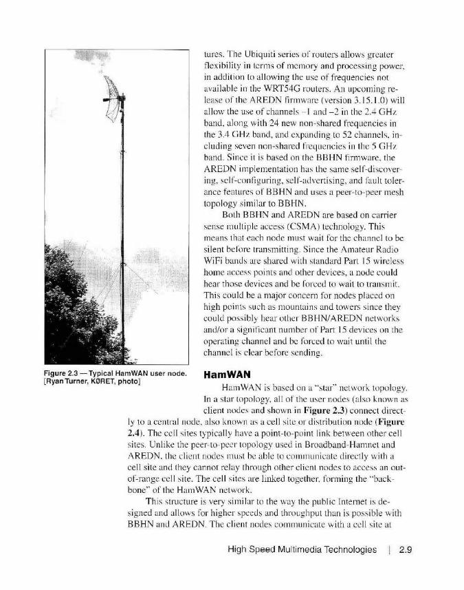
Figure 2.3 - Typical HamWAN user node. [Ryan Turner, K0RET, photo]
lures. The Ubiquiti series of routers allows greater flexibility in terms of memory and processing power, in addition lo allowing the use of frequencies not available in the WRT54G routers. An upcoming release of the AREDN firmware (version 3.15.1.0) will allow the use of channels -1 and - 2 in the 2.4 GHz band, along with 24 new non-shared frequencies in the 3.4 GHz band, and expanding to 52 channels, including seven non-shared frequencies in the 5 GHz band. Since it is based on the BBHN firmware. the AREDN implementation has the same self-discovering, self-configuring. self-advertising, and fault tolerance features of BBHN and uses a peer-to-peer mesh topology similar to BBHN.
Both BBHN and AREDN are based on carrier sense multiple access (CSMA) technology. This means that each node must wait for the channel to be silent before transmitting. Since the Amateur Radio WiFi bands are shared with standard Part 15 wireless home access points and other devices, a node could hear those devices and be rorced to wait to transmit. This could be a major concern for nodes placed on high points such as mountains and towers since they could possibly hear other BBHN/AREDN networks and/or a significant number of Part 15 devices on the operating channel and be forced to wait until the channe l is clear before sending.
Ham WAN Ham WAN is based on a .. star .. network topology.
In a star topology, all of the user nodes (also known as client nodes and shown in Figure 2.3) connect direct
ly to a central node, also known as a cell site or distribution node (Figure 2.4). The cell sites typically have a point-to-po int link between other cell sites. Unlike the peer-to-peer topology used in Broadband-Hamnet and AREDN , the cl ient nodes must be able to communicate directly with a cell site and they cannot relay through other client nodes to access an outof-range cell site. The cell sites are linked together. forming the .. backbone" of the Ham WAN network.
This structure is very sirnilar to the way the public Internet is designed and allows for higher speeds and throughput than is poss ible w ith BBHN and AREDN. The client nodes communicate with a cell site at
High Speed Multimedia Technologies 2.9

S GHz using a standard unmodified MikroTik router and a high gain parabol ic mesh grid antenna. The cell sites communicare with each other over a separate link, usually at 3.4 GHz (9 cm) or 5 GHz (S cm).
Harn WAN operates in the Part 97 Amateur Radio portion of the S GHz band, allowing HamWAN cell si tes to be placed on high points such as towers or mountains without worry of interfe rence from Part 15 users. The typical cell site operates on multiple channels using three 120-degree sector antennas, spreading the user load over three separate frequencies. Since the lin k between ce lls si tes is on yet another frequency, there is no interaction between users of one cell site and the users of another cell si te . Ideall y. the client node frequencies arc different at each cell si te. virtually eliminating the CSMA data colli sion issues inherent in the BBHN/AREDN and standard WiFi technologies. (Ir l wo nodes that can't hear each other are sending to a third node that can hear both, the data "collides" and wi II have to be re transmitted. )
Figure 2.4 - A typical HamWAN cell s ite. [Ryan Turner, KORET, photo]
For communications between the cell sites and cli ent nodes, Harn WAN uses the MikroTik Nv2 commun ication protocol based on 802. 11 n. Nv2 allows the use of time division mul tiple access (TOMA) technology as an addi tional method to reduce packet collisions and enhance overall network throughput. Using TOMA and Nv2, the cell site all ocates transmission time to the client nodes dynam ically. The cell site will broadcast a "schedule" tell ing the clients when they should transmit
2. 10 Chapter 2
and the amount of time they can use based on client requests for bandwidth. This helps prevent data coll isions as well as addressing the hidden node issue. thereby providing for increased overall data throughput. Using Nv2 also al lows for the implementation of quality of service (QoS) which allows you to pri ori tize the traffic on your HSMM network.
To ensure that only licensed amateurs can use the network, Ham WAN uses digital ··certificates" to authenticate users. A digi tal certificate is an ··electronic document" or block of data that is created by an entity known as a certi ficate authority. or CA. A CA is basically an authorized server that uses public-private key cryptology to generate a un ique certificate used to identify the sender. Usi ng the public-private key cryptology and digital certi ficates in this manner is also known as two-factor authentica-
tion. While not impossible. it is very difficult and not really practical to '"crack" the keys used in public-private key cryptology. This means that there is an extremely low chance of someone pretending to be you. While Part 97 rules prohibit the secure encryption of data, there is no prohibition
for using digital certificates to authenticate the sender of the data. If you use ARRL"s Logbook of the World (LoTW). you a re a lready
using a digita l certificate. As part of the process of upload ing your log to LoTW, you d igitally "sig n" your log with the certificate you c reated using the Trusted QSL (TQSL) program on your workstation. This certi ficate is used by LoTW to ensure that it's really you uploading the log.
HamWAN ac tually uses the LoTW and TQSL certificate authority system to generate a digital cenificate for use on the Ham WAN network, thereby ensuring that only licensed hams can create a valid certificate to access the H am WAN network. Every data packet your node sends is "signed"' with your certi ficate and is used by the Harn WAN network to identify that you are an authorized user or the network. T hi s avoids the rules against encrypting the data since the data itself is not encrypted, but the ce1tificate information added to each data packet uses two-factor en
cryption to provide veri fi cation that the d ata did indeed originate from your node.
Keep Up-To-Date
References
As is often the case with experimental technology, the technologies
used to implement Amateur Radi o HSMM networks are in a constant state of flux . Similar to the case of the Sony Betamax versus the VHS videotape format "wars" of the 1970s (I still say Betarnax was belier). over time there will more than like ly be some standardization as to which technology is best suited for the various applications you plan to implement on your HSMM netwo rk. In order to stay up-10-date with the various technologies, I recommend that you visit the various HSMM development group websites for the most current information.
One final reminder: While you can access and use the public Internet over your Amateur Radio HSMM net work. it shou ld not be used as a repl acement for regular Internet access. It fall s to you to ensure that a ll public Inte rnet usage from your HSMM network is complian1 with Part 97 of the FCC rules.
www.aredn.org www.broadband-hamnet.org www.fcc.gov www. HamWAN.org www.memHamWAN.org www.wikipedia.org
High Speed Multimedia Technologies 2.11

Chapter 3
HSMM Equipment for Amateur Radio
Since the equipment used in an Amateur Radio HSMM network is primarily repurposed commercial WiFi equipment, much of it is readily available from eBay (www.ebay.com), hamfests. and anywhere else you can buy surplus e lectronic equipment. Before you go out and purchase any equipment, you should decide which HSMM technology you plan to implement. The most importan t th ing to remember as you build out your network is what equipment the other hams in your area plan to use, or what might be in use in any Amateur Radio HSMM networks already operating 111 your area.
Unlike CW and SSB, where "any old rig will work;' every node in an HSMM network must be compatible w ith the HSMM technology that you plan to deploy. In the case of Broadband-Hamnet and AREDN. the devices must operate on the same frequ ency and run a compatible version o f firmware. It's a good idea to find, or gather up, a group of amateurs in your area interested in sett ing up an HSMM network. Get together and plan o ut what technology is best for your group's needs and goals. Do some rough site locatio n planning and use the survey and mapping tools discussed in Chapter 8 to determine the coverage of the location s where you plan to deploy your equipment. In my case. most of the interested members of my club, the O live Branch Amateur Radio C lub (OBARC). are new to HSMM and want to start out w ith the Broadband-Hamnet implementation using the readil y available and inexpensive Linksys WRT54G routers .
Unfortunately for me. I live about 10 miles away from the rest of the group and am located in the equivalent of an "RF no man 's land" as far as
HSMM Equipment for Amateur Radio 3.1

3.2 Chapter 3
microwave goes. While I live near the top of a small hill that works great for the HF bands, the terrain between my station and the rest of the group just isn' t workable for direct line-of-sight microwave communication. What we ended up doing to resolve this was to enlist the aid of a ham living about halfway between me and the other members of our HSMM group to a llow us space on his tower for a BBHN node. While as yet untested , the te rrain and microwave path mapping tools suggest that this "relay" link should do the trick and make the next hop to the top of one of the two water towers in Olive Branch where we plan to deploy another node for the rest of the group to access . Since this '·relay" link clears the majority of path ohstructions for me. I should be able to link up with the other members of our group.
Another thing to consider when deciding on the HSMM technology to choose is what you plan to do with your network once you have it deployed . Aside from the usual tinkering and experimenti ng, our group would also like to explore some of the public service possibilities for our HSMM network. Since we are located in the middle of "Tornado Alley," subject lo the annual threat of ice storms, and vi rtually on top of the New Madrid fault line, disaster preparedness is near the top of our club's list of things to think about.
With many of our club members already involved with the local emergency management agencies, fi re departments, and the like, it would be a natural for our group to think about expanding our HSMM network to provide coverage to these various agencies. One train of tho ught would be to set up a voice-over- IP phone system with an IP pho ne a t each agency li nked to our HSMM network. This would rrovide a vital backup means of communication between the various agencies if a ll usual means of communications fai l.
Some of you may think of this as excessive redundancy, but when Hurri cane Katrina hit New Orleans in 2005. it took out all power and communications for the en tire area, p1imarily because of the flooding that came afterwards . Cell phone towers, repeaters, landlines, and all other normal modes of communication fa iled as they became flooded , their generators ran out of fuel, or their batteties died. With its low power draw, an HSMM node can operate on solar power and/or batteries for an extended amount of t ime, if not indefinite ly, making it an ideal option for communications "when a ll e lse fails."
Once you decide on wh ich HSMM technology you wish to deploy, you're ready to start acquiring the equ ipment needed to make it happen. The rest of this chapter wi ll discuss the various pieces of equipment you will need to build out your HSMM network.

Linksys WRT54G Wireless Router For Broadband-Hamnet, you will most like ly start out with an inex
pensive Linksys WRT54G (Figures 3.1 and 3.2) or Ubiquiti 2.4 GHz wireless router. Available from sources such as e Bay and hamfests, the Linksys WRT54G series of wireless WiFi routers is at the heart o r much of the initial development of Amateur Radio HSMM networking. I was able to purchase several WRT54G routers from eBay for $15 each.
Designed for use in home wireless networks. the WRT54G has four 100 megabit per second (Mbps) Ethernet LAN ports, and one l 00 Mbps WAN port. Two small whip antennas are connected to the rear of the WRT54G using RP-TNC connectors. (See the sidebar on WiFi Antenna Connectors for why consumer WiFi stuff has such strange RF connectors.) The BBHN firmware allows you to select and use the right, left, o r both antenna ports. The WRT54G supports the IEEE 802. l l b ( 11 Mbps) and 802. l l g (54 Mbps) wireless modes. The BBHN firmware uses the Linksys WRT54G in 802.1 lg-only mode, thereby avoiding the spread spectrum
Figure 3.1 -The Linksys WRT54G wireless router.
Figure 3.2 - Linksys WRT54G rear view.
HSMM Equipment for Amateur Radio I 3.3

Wifi Antenna Connectors Did you ever wonder why your home WiFi devices use
those strange off-the-wall connectors that you can't find matching connectors for? Under the FCC rules for Part 15 devices, section 15.203, to be exact, the device must be designed to ensure that only the antenna type provided by the manufacturer can be used with the device. The FCC requires either a permanent fixed antenna or the use of a unique antenna connector. By unique, the FCC means that the manufacturer must use a connector that is not read ily available at a local electronics supply store or in an electronic parts supply catalog.
This is how we ended up with all those MMCX, MCX, and the reverse polarity SMA, BNC, and TNC type connectors. Since those connectors have become readily available, newer types of "unique" connectors have been created. There are now left hand threaded N, BNC, TNC, and SMA connectors. Who knows what else they'll come up with as newer connectors become avai lable and add to our already overflowing box of adapters and pigtails.
lllllllllllllllllllllllll\1 11\lllllll ll\\ll\l\\l\ll\l\\ll\ll\\l\l\\ll\ CDF50D324594
lllllll lllllllllllllllllllll\llllllll\llllll\lllllll ll\ll \\l\111\\\ll\ OOOF662C9330
M ade In C t1ln•
Figure 3.3 - Be sure to check the Linksys Product ID label for compatibility with the BBHN and AREDN firmware.
Table 3.1
transmission power restrictions associated with the 802.11 b mode.
Originally released in 2002, the WRT54G series continued in production until 2009. In 2003, Linksys was acquired by Cisco. That same year, the Free Software Foundation (FSF) began working with Cisco to resolve claims that the firmware used in the WRT54G violated the open source terms of licensing for programs copyrighted by FSF. Linksys/Cisco began releasing the source code for the WRT54G as open source in 2003 and as part of a legal settlement wi th FSF in 2009. This opened the floodgate for developers to begin writing new firmware for the WRT54G. With the source code now available, the OpenWrt. DD-WRT, Tomato, and other open source projects developed an improved firm ware alternative to the standard factory firmware on the Linksys WRT54G and other Linux-based routers. OpenWrt is used as the founda-tion for the Broadband-Hamnet HSMM implementation.
WRT54G Models Compatible with Broadband-Hamnet Firmware
WRT54G Version 1.0· WRT54G Version 1.1 - 4.0 .. WRT54GS Version 1.0 - 4 .0 .. WRT54GL Versions 1.0 and 1.1
·warning: WRT54G Version 1.0 uses a 5.0 V de power adapter. All other models use 12V de.
""WRT54G and WRT54GS Versions 5.0 and higher are not compatible with Broadband-Hamnet
The Linksys WRT54G is available in a number of configurations with differing internal CPU speeds and memory capacity. Be careful when purchasing a WRT54G online, as only certain models of the WRT54G can be used for BBHN. Be sure to check the product ID label as shown in Figure 3.3. Table 3.1, developed with information from the BroadbandHamnet website, lists the versions of the WRT54G than can be used with the BBHN firmware.
The BBHN firmware allows you to set the power
3.4 1 Chapter 3

dB vs dBm vs Watts Because of the low power and signal levels
typically found at microwave frequencies, the power output and receive signal strength of most microwave RF devices is measured in dBm rather than watts. This can get confusing, especially since most of us are used to seeing power output in watts or mill iwatts. Add to that the usage of the terms dB, dBm, and dBi , and it's easy to get lost in a hurry.
dB is simply the ratio between two values, such as front-to-back antenna gain. The mathematical formula to calculate dB is 10 log (p1/p2). Every increase of 3 dB equates to a doubling of the signal strength. Similarly, every decrease of 3 dB in signal strength equates to a halving of the power. Most often, you wi ll see dB used to describe a factor of gain, but since dB is used to depict a ratio between two values, there is no way to determine exactly how much power or signal strength is actually depicted by the gain.
dBm is used to depict an absolute power level relative to 1 milliwatt. dBm is still the ratio of two values, but the second value used is always 1 milliwatt so the resulting value is the power output as it relates to 1 milliwatt. Since we're usually working with low power levels at microwave frequencies, dBm was chosen as the unit of power measurement instead of watts. The formula to calculate dBm is P dsm = 10 log,
0 (P mw) . To convert dBm to milliwatts,
you can use the formula p mW = 1 OidBmllOI. As with dB, every increase of 3 dBm equates to a doubling of the power output. For example, +10 dBm is 10 mW, and +13 dBm is 20 mW.
To add even more confusion to the mix, there is also the term dBi. This is typically used to describe the gain of an antenna relative to our old imaginary friend, the isotropic radiator, which is a theoretical antenna that radiates equally in all directions.
output of the WRT54G from a minimum of I dBm (1 mW) to a maximum or 19 dBm (79 mW). See the sidebar for a discussion on dB, dBm and watts as it relates to transmitter power.
While we're on the subject of power, the Linksys WRT54G models typica lly draw about 7 W of de power. This allows the Linksys routers to be used in low power situations, running from battery and/or solar power. The WRT54G can also be removed from
Figure 3.4 - The Linksys WRT54G mounted in an outdoor box with a 24 dB gain mesh grid antenna.
its plastic case. mounted in a watertight outdoor box, and powered using Power-over-Ethernet (PoE) runn ing over the standard Category 5 or 6 (CAT5/6) cable used for the data connection to your workstation or local network. In Chapter 8 we' ll show you how to build your own outdoor box for the WRT54G (Figure 3.4).
HSMM Equipment for Amateu r Radio 3.5
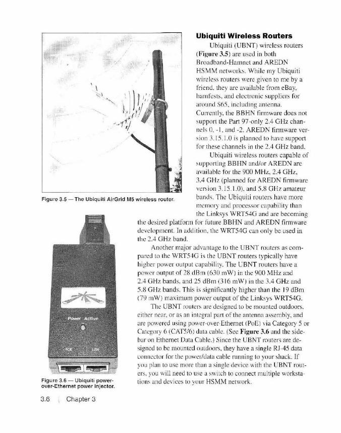
Ubiquiti Wireless Routers Ubiquiti (UBNT) wi reless routers
(Figure 3.5) are used in both Broadband-Hamnet and AREDN HSMM networks. Whi le my Ubiquiti wireless routers were given to me by a friend, they are available from eBay, hamfests. and electronic suppliers for around $65. including antenna. Curren1ly, the BBHN firmware does not suppo rt the Part 97-only 2.4 GHz channels 0. - 1, and -2. AREDN fi rmware version 3.15 .1 .0 is planned to have support for these channels in the 2.4 GHz band.
Ubiq uiti wireless rou ters capable of supporting BBHN and/or AREff\I are available for the 900 MHz, 2.4 GHz, 3.4 GHz (planned for AREDN firmware version 3. 15.1.0). and 5 .8 GHz amateur
Figure 3.5 - The Ubiquiti AirGrid MS wireless router. bands. The Ubiquiti routers have more memory and processor capabil ity than
Figure 3.6 - Ubiquiti powerover-Ethernet power injector.
3.6 Chapter 3
the Linksys WRT54G and are becoming the desired platform for future BBHN and AREDN fim1ware development. In addition, the WRT54G can on ly be used in the 2.4 GHz band.
Another major advantage to the UBNT routers as compared to the WRT54G is the UBNT routers typically have higher power output capability. T he UBNT routers have a power output of 28 dBm (630 mW) in the 900 MHz and 2.4 G Hz bands, and 25 dBm (3 16 mW) in the 3.4 GHz and 5.8 GHz bands. This is s ignificantly higher than the I 9 dBm (79 mW) maximum power output of the Linksys WRT54G.
The UBNT routers are designed to be mounted outdoors, e ither near, or as an integral part of the antenna assembly, and are powered using power-over-Ethernet (PoE) via Category 5 or Category 6 (CAT5/6) dala cable. (See Figure 3.6 and the sidebar on Ethernet Data Cable.) Since the UBNT routers are designed to be mounted outdoors, they have a single RJ-45 data connector for the power/data cable running to your shack. If you plan to use more than a single device with the UBNT routers. you will need to use a switch to connect mulliple workstations and devices to your HSMM network.

Ethernet Data <;able
Most commonly found in computer Ethernet data cables, and defined by the ANSI/ TIA/EIA-568-A and TIA/EIA-568-B standards, Category (CAT) 5, 5e, and 6, use four pairs
' of #20 or #24 AWG twisted copper wires, usually unshielded, and most commonly having an 8-pin modular RJ-45 connector at each end. You may also hear this type cable referred to as unshielded twisted pair (UTP) cable. An RJ-45 (also known as an 8P8C) connector looks exactly like a larger version of the 4-pin RJ- 11 connector used in many home telephone wiring systems. These connectors are crimped onto the cable ends to create an Ethernet data cable.
CAT5 cable is rated at 100 megabits per second (Mbps) over a length of 100 meters. An updated version of this cable, known as CAT5e allows for data speeds up to 1 Gbps up to a distance of 1 oo meters. More recently, CAT6 has become the standard for computer Ethernet data cables, allowing for data speeds of 1 gigabit per second (Gbps) over a distance up to 100 meters. Longer cable runs can be created by using repeaters (bridges), hubs, or switches to join the cable segments.
There is another older, but similar, cable type known as CAT3. CAT3 is the cable often used in the wiring of your home telephone system and was used for Ethernet with data speeds up to 10 Mbps over a length of 100 meters.
Newer versions of Ethernet data cables are designated CAT 7 and CAT 8. Defined in the ANSl/TIA/EIA-568-8.2-1 standard, CAT? cable can be used at speeds up to 10 Gbps, and CATS cable will be able to carry data at speeds up to 40 Ggbps over a distance of at least 30 meters.
You may also hear the term 1 OOBase-T and 1 OOOBase-T when referring to Ethernet devices and cables. To decipher this description, the number represents the data speed (in megabits per second) , and the "Base" indicates that it is a baseband technology where the cable is used to transfer a single channel of data rather than multiple channels of RF or light. The final lette r (or letters) refers to the physical cable type. In our example the 'T' refers to standard twisted pair copper cable. This nomenclature could also be used to describe a fiber optic cable, where it would be designated something like 1 OOBase-FX.
Since most modern Ethernet devices are capable of speeds up to 1 Gbps, you should use either CAT5e or CAT6 in your cabling. The type of cable can be identified by looking at the cable identification stamped on the cable's insulating outer jacket. Also, you should use an outdoor-rated version of the data cable you plan to use in any outdoor portions of your HSMM installation.
As with the Linksys WRT54G, only certain mode ls of the UBNT are supported by the BBHN and AREDN firmware. Please check the equipment matrix at the Broadband-Hamnet and AREDN websites for a li st of currently supported equipment.
Mikrolik Wireless Routers MikroTi k is a Latvian manufacturer of wire less networking equip
ment. The MikroTik Metal SSHPN (Figure 3.7) is the recommended (first generation) wireless router (also known as a radio modem in Ham WAN terminology) for use as a c lient, sector, or point-to-point node in a Ham WAN HSMM network. I purchased m y MikroTik Metal SSHP direct from Baltic Networks for $86 plus shipping .
HSMM Equipment for Amateur Radio 3.7

3.8 i Chapter 3
Figure 3.7 -The MikroTik Metal 5SHPN wireless router.
Unlike the Linksys
and Ubiquiti wire less routers used in BBHN and A REDN , there are no fi rmware changes re
quired to use the Mi kroTik rou ters with HamWAN. To prevent unauthorized users from accessing your Ham WAN network, d igital certificates embedded within
the data packets are used to authent icate users on
the network and to control access to network resources.
The MikroTi k Metal 5SHPN operates in the 5 GHz band and uses
Ix 1 M IMO technology. The Ix 1 stands for I antenna and I spat ial stream. Because MIMO technology often uses multiple antennas for transmi t and
receive, multiple data channels (known as spatial streams) can be created that increase thro ug hput speed. A modulation and coding speed (MCS)
index is used lo ca lculate the maximum throughput possible based on the number of spatial streams. modulation type, and cod ing rate.
Fortunately. we don' t need to know how all this actually works, si nce it 's handl ed internally in the device and by the Ham WAN network configuration used in your local ne twork. In a nutshel l. the MikroTik Metal SSHPN devices support MCSO (6 Mbps) up to MCS7 (I SO Mbps) usi ng the IEEE 802 .11 n mode or 54 Mbps operat ing in the 802.1 la mode.
MikroTik w ire less rou ters are available for the 900 MHz. 2.4 G Hz. and 5 G Hz bands. T he 5 GHz un it recommended for use as a c lient node has a hefty power output of 30 dBm ( I W) using the MikroTik 802 .11 nhased Nv2 mode in the S GHz band. The MikroTik Metal 5SHPN is housed in a complete ly waterproof. metal case and it typically mounted c lose to the recommended mesh gri d parabolic antenna. Power-overEthemet (PoE) is used to provide power to the MikroTi k 's sing le Etherne t connection over a standard CATS o r CAT6 cable .
A newer. second generation Ham WAN site configuration uses the MikroTik RB9 I 2 UAG-SHPnD-OUT wireless router for the client nodes

and cell sites . This radio modem supports 2x2 MIMO technology, allowing for speeds up to 300 Mbps. The first genera tion MikroTik Metal 5SHPN is 100% compatible with the newer second generation Ham WAN network.
We' ll cover the configuration and insta ll ation of the MikroTik radio modems for use in a Ham WAN HSM M network in Chapter 8 .
Antenna Feed Line
Antennas
At microwave frequencies, antenna feed line loss is a major issue. At 2.4 GHz, RG-58 coax has a loss o f 32 dB per I 00 feet, RG-8X has a loss of 23 .1 dB per 100 feet, and even the top o f the line LMR-400 coax (RG-8 s ize) has a loss of 6.8 dB per I 00 fee t. You need the semi-rigid hardline cable such as Heliax to have any sort of acceptable loss a t microwave frequenc ies. The Yx-inch Heliax has a loss of 5.9 dB per 100 feel, and 'A-inch Heliax has a loss of 3.9 dB per 100 feel. At 5 GHz, things get even worse, with RG-58 being more of a dummy load than a feed line (loss of 51 dB per I 00 feet). LMR-400 has a loss o f I 0.8 dB per I 00 feet and even Y~inch Heliax has a loss of 6.6 dB per I 00 feet.
The moral of the story here is to keep your feed line as short as possible. This is why the Ubiquiti and MikroTik routers are mounted at the antenna and de power is feel to the device using PoE on the data cable. There·s no worry about signal lo~s on the data cahle. Category Se and CAT 6 cable are rated at 1 gigabit speed for a cable length up to I 00 meters. Things get a li tt le bit trickier with the Linksys WRT54G routers, since they are not made to live outdoors. Rather than have a long run of lossy feed line, I recommend mounting the Li nksys WRT54G in a waterproof outdoor box with a very sho1i run o f feed line to the antenna. I' ll show you how to build a WRT54G outdoor box in Chapter 8.
When it comes to microwave freque ncies, the antenna is everything. You can achieve far more performance with a higher gain antenna than you can simply by increasing your power o utput.
W hen building your HS MM client node. you will most like ly want to use a high-gain outdoor antenna. Typicall y. this antenna will be a Yagi or w ire mesh grid antenna. Matching the ant enna polarization be tween your HS MM nodes is critical. At microwave freq uencies, a 90° mismatch in po larization, which can occur w hen the transmi tting node uses horizontal polarization and the receiving nm.le uses vertical polarization , results in a theoretical infinite loss. Due to reflectio n and other atmospheric conditions, the actual loss will never be infini te, but it will still be significant. Typically, BBHN and AREDN networks use vertical po larization, while
HSMM Equipment for Amateur Radio 1 3.9
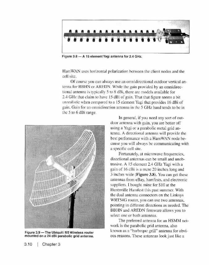
cJll I 11 I ~1-l tll-ttt~ , , Figure 3.8- A 15 element Yagi antenna for 2.4 GHz.
Ham WAN uses horizontal polarization between the client nodes and the cell site.
Of course you can always use an omnidirectional outdoor vertical antenna for BBHN or AREDN. While the gain provided by an omnidirectional antenna is typically 5 to 8 dBi, there are models available for 2 .4 GHz that claim to have 15 dBi of gain. That that figure seems a bi t unrealistic when compared to a 15 element Yagi that provides 16 dBi of gain. Gain for an omnidirection antenna in the 5 GHz band tends to be in the 5 to 6 dBi range.
In general, if you need any so11 of outdoor antenna with gain, you are better off using a Yagi or a parabolic metal grid antenna. A directional antenna will provide the best pe1fom1a11ce with a Ham WAN node because you will a lways be conununicating with a specific cell site.
Fortunately, at microwave frequencies, directional antennas can be small and unobtrusive. A 15 element 2.4 GHz Yagi with a gain of 16 dBi is a mere 20 inches long and 3 inches wide (Figure 3.8). You can get these antennas from eBay, hamfests, and electronic supplie rs. I bought mine for $10 at the Huntsville Hamfest th is past summer. With the dual antenna connectors on the Linksys WRT54G router, you can use two antennas, pointing in different directions as needed . The BBHN and AREDN tinnware allows you to selec t o ne or both antennas.
Figure 3.9 - The Ubiquiti MS Wireless router mounted on a 24 dBi parabolic grid antenna.
The preferred antenna for an HSMM network is the parabolic grid antenna, also known as a "barbeque grill" antenna for obvious reasons. These antennas look just like a
3.1 O Chapter 3

Figure 3.1 O - A 5 GHz parabolic grid antenna for HamWAN. Note that this antenna is configured for horizontal polarization.
curved barbeque gri ll and offer excellent gain and directivi ty. Many of the Ubiquiti wireless routers, such as the Ubiqu it i M5 shown in Figure 3.9, are designed to mount as an integral part of the antenna, el iminating the need for feed line altogether.
Depending on the size of the antenna, gain will typically run from IS to 24 dBi. A new 24 dBi gain grid parabolic antenna is available on eBay for about $50. The recommended 31 dBi S GHz Poynting parabolic gri d antenna for my HamWAN node cost $8 1 new from Titan Wireless. Determining the polarization for this type of antenna is somewhat the reverse of what you would expect. The antenna shown in Figure 3.9 is configured for BBHN/AREDN's recommended veriical polarization. while the antenna in Figure 3. IO is contigured for HamWAN's recommended horizontal polarization. Remember that proper antenna polarization is critical at microwave frequencies, so be sure to verify that you have your antenna properly configured for the polarization used in your HSMM network.
lf you absolutely. posi tively have to have an amplifier, there are a few that you can find
inexpensively on places such as eBay. Be careful though - as you go up in power levels at microwave frequencies. the equipment can get expensive in a hurry. You al so need to pay much closer attention to proper RF safety techniques. Again. my personal recommendation is to try alternate methods such as higher gain antennas or a relay site before going the amplifier route.
For test ing my weak link issues, Twas able to purchase a Hyperlin k Technologies HA240 1-AGC250 2.4 GHz amplifier on eBay for $50 (Figure 3.1 1 ). Hyperl ink Technologies was purchased by L-Com in 2007. but there are still a number of these amplifiers available as used or su rplus. This amplifier >v iii boost the 19 dBm (79 mW) power output of the Linksys WRT54G router to nearly 24 dBm. or about 250 mW This amplifier also incorporates a 17 dB receive preamplifier. which would likely be of more use than the extra power output - you could just use a Ubiquiti router and have higher power out-of-the box, without the need for an amplifier.
Hyperl ink amplifiers are available as both indoor and outdoor models.
HSMM Equipment for Amateur Radio I 3. 11
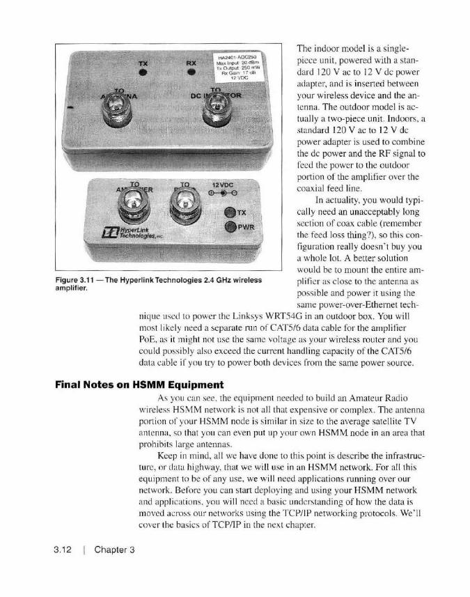
RX • HA2401 .A.GC250 M~ 1nput 20 dBm h Outplft 250 mW
Rx Gain 17 OB 12voc
The indoor model is a sing lepicce unit, powered with a standard 120 V ac to 12 V de power adapter, and is inserted between your wireless device and the antenna. The outdoor model is actuall y a two-piece uni t. Indoors, a standard 120 V ac to 12 V de power adapter is used to combine the de power and the RF signal to feed the power to the outdoor portion of the amplifier over the coaxial feed line.
~ljyperL/nk tL: TBChnolog/es,11c.
. TX . PWR
In actuality, you would typicall y need an unacceptably long section of coax cable (remember the feed loss thing?), so this configuration really doesn' t buy you a whole lot. A better solution would be to mount the entire ampli fier as close to the antenna as Figure 3.1 1 - The Hyperlink Technologies 2.4 GHz wireless
amplifier. possible and power it using the same power-over-Ethernet tech
nique used to power the Linksys WRT54G in an outdoor box. You will most li ke ly need a separate run of CATS/6 data cable for the amplifier PoE. as it might not use the same voltage as your wireless router and you could poss ibly also exceed the current handling capacity of the CATS/6 data cable if you try to power both devices from the same power source.
Final Notes on HSMM Equipment
3. 12 Chapter 3
As you can see. the equipment needed to bu ild an Amateur Radio wireless HSMM network is not all that expensive or complex. The antenna portion of your HSMM node is similar in size to the average satellite TV antenna. so that you can even put up your own HSMM node in an area that prohibits large antennas.
Keep in mind, al l we have done to th is point is describe the infrastructure, or da ta highway, that we will use in an HSMM network. For all this equipment to be of any use, we will nced applications running over our network. Before you can start deploying and using your HSMM network and applications. you wi ll need a basic understanding of how the data is moved across our networks using the TCP/IP networking protocols. We' ll cover the basics of TCP/IP in the next chapter.

References www.aredn.org www.balticnetworks.com www.broadband-hamnet.org www.dd-wrt.com www.hamwan.org www.l-com.com www.mernharnwan.org www.mikrotik.com www.openwrt.org www.polarcloud.com/tomato www.titanwirelessonline.com www.ubnt.com www.wikipedia.org
HSMM Equipment for Amateur Radio 3. 13

Chapter 4
TCP /IP for HSMM
Did you ever wonder how your web browser knows where to go to
get to your favorite website or retrieve your e-mail? How does the websi te know where to send che information back to you0 How does an e-mai l someone sends you know where to go to get to your inbox? Thi s is all done through the magic of the TCP/IP protocol suite.
Research and developmem conducted by the Defense Advanced Research Projects Agency (DARPA) in the late 1960s resulted in the development of one of the first computer net works. the Advanced Research Project Agency Network (ARPANET). Based on that work, Robert E. Kahn and Vinton Cerf developed the specilications for the Internet Transmission Control Protocol in the early 1970s. This resulted in Transmission Control Protocol/Internet Protocol (TCP/IP) version 4 (1Pv4) that is commonly used in computer networks and the Internet today.
When referring to TCP/IP, you wi ll o rten hear it called just "IP" or " lPv4" to distinguish the o lder version 4 protoco l from the newer IP version 6 (1Pv6) pro tocol. In 1982. the US Department of Defense adopted TCP/IP as the standard for all military computer networking. Throughout the la te 1980s, as the Internet we know today began to form, TCP/IP was promoted as the protocol of choice. Eventually it won out over IBM 's System Network Archi tecture (SNA ). Open Systems Interconnection (OSI). Microsoft' s NetBIOS, and Xerox Network System (XNS) networking protocols among others. ATT's release of their TC P/IP source code for UN IX in 1989, along with Microsoft's release of a TCP/IP pro tocol stack for Windows 95, firmly establi shed TCP/IP as the primary protocol for what would come to be known as the World Wide Web.
TCP/IP for HSMM 4.1
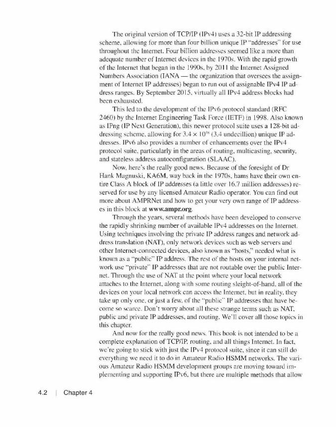
4.2 Chapter 4
The original version of TCP/IP (1Pv4) uses a 32-bit IP addressing scheme. allowing for more 1han four billion unique IP "addresses .. for use throughout the Internet. Four billion addresses seemed like a more than adequate number of Internet devices in the 1970s. With the rapid growth of the Internet that began in the 1990s. by 20 I I the Internet Assigned Numbers Association (IANA - the organization that oversees the assignmen! of Internet IP addresses) began to run out of assignable £Pv4 IP address ranges. By September 2015. virtually all 1Pv4 address blocks had been exhausted.
This led to the development of the I Pv6 protocol standard (RFC 2460) by the Internet Engineering Task Force (IETF) in 1998. Also known as !Png (IP Next Generation). this newer protocol suite uses a 128-bit addressing scheme. allowing for 3.4 x 10.1 ~ (3..+ undecillion) unique IP addresses. 1Pv6 also provides a number of enhancements over the 1Pv4 protocol suite. particularly in the areas of routing, multicasting, security, and stateless address autoconfigurat ion (SLAAC).
Now. here's the really good news. Because of the foresight of Dr Hank Magnuski, KA6M, way back in the 1970s, hams have thei r own entire Class A block of IP addresses (a little over 16.7 million addresses) reserved for use by any licensed Amateur Radio operator. You can find out more about AM PR Net and how to get your very own range of TP addresses in this block at www.ampr.org.
Through the years, several methods have been developed to conserve the rapidly shrinking number of available 1Pv4 addresses on the Internet. Usi ng techniques involving the private IP address ranges and network address translation (NAT), only net work devices such as web servers and other Internet-connected devices, al so known as "hosts," needed what is known as a "public" IP address. The rest of the hosts on your internal network use "private" IP addresses that are not routable over the public Internet. Through the use of NAT at the point where your local network attaches lo the Internet, along with some routing sleight-of-band. a ll of the devices on your local network can access the In ternet, but in reality. they take up only one. or just a few. of the "public" IP addresses that have become so scarce. Don't woJTy about all these strange terms such as NAT. public and private IP addresses, and routing. We' ll cover all those topics in thi s chapter.
And now for the really good news. This book is not intended to be a complete explanation of TCP/TP, rout ing. and all th ings Internet. In fact, we're going to stick with just the 1Pv4 protocol suite, since it can still do everything we need it to do in Amateur Rad io HSMM networks. The various Amateur Radio HSMM development groups are moving toward implementing and supporting IPv6. but there are multiple methods that al low
the use of the IPv4 protocol over an TPv6 network. Realistically, it will be a while before you' ll need to wtmy about ditching TPv4 in your HSMM network and migrating up to IPv6.
There have been entire books wri tten about TCP/IP. both IPv4 and IPv6. It 's just not possible to cover everything about TCP/IP in a single chapter. not to mention that !Pv6 sti 11 gives me headaches and ['II take any excuse I can get to avoid talking about it. In stead. if you want to learn all you can about TCP/IP, including 1Pv4 and 1Pv6. I recommend reading the free online book, The TCP/IP Guide, at www.tcpipguide.com. Rather than try to do a complete dissertation on all things TCP/IP, we' ll focus on the aspects of TCP/IP you can use as it relates to building out your own Amateur Radio HSMM network.
Putting the Cart Before the Horse One of the hardest parts of discussing TCP/ IP in such a limited space
is finding the proper order to lay out the foundation for the information we need lo talk about. In the case of TCP/IP. as you may have already seen. I've had to mention things I haven' t delincd yet, but to try to define them as you encounter them can only lead to further confusion as the acronym count begins to mount. This is why many people fi nd trying to learn TCP/IP so frustrating - there are just so many little pieces that have to be covered. There 's no good way to avoid this. but I'll try to keep the jumping around to a minimum and stick to \Vhat you need to know about how TCP/lP works as it relates to Amateur Radio HSMM networks.
How TCP / IP Works !n a TCP/IP network, data is sent in packets between dev ices. Each
packet of data is "encapsulated" in what is called an IP datagram, which contains the source and destination IP addresses along with the data itself in mu ltiple data packets. An IP datagram consists of a header section and the actual data. Figure 4.1 shows the structure of an IP datagram header. As a general rule, you really will not need to know much about the IPv4 header, as much of th is is handled automatical ly by your network devices. It is presented here for completeness, as we will be dealing with some of the information contained in the header later in this chapter.
Every IPv4 header contains a series of 32-bit data words, with a minimum of 4 words ( l 28 bits). The header can be longer if there is data in the Options fields, but the length of the enti re header is specified within the header itself. As you can see, there are a number of data fields contained within each header.
TCP/IP fo r HSMM I 4.3

Version IHL Type of Service Total Length
(4 Bits) (4 Bits) (8 bits) (16 bits)
Identification D M Fragment Offset
(16 bits) F F (13Bits)
Time To Live Protocol Header Checksum
(8 Bits) (8 Bits) (16 Bits)
Source Address
(32 Bits)
Destination Address
(32 Bits)
Options
(0 or more 32 Bit words)
Figure 4.1 - The 1Pv4 datagram header format.
4.4 Chapter 4
Version Field The firs t field in the heade r is the version fie ld. This w ill contain a
4for1Pv4 and 6 for 1Pv6. This is how the ne lwork devices know whether they are dealing with an 1Pv4 or 1Pv6 datagram.
IHL Field The second fie ld in the heade r is the Interne t Header Field (IHL).
Th is specifies the number of 32-bit words in the header. and is a lso used to calculate where in the da tagram the actual data begins.
Type of Service This lie ld was orig inally defined as the Type of Service (ToS) field,
but was redefin ed in IETF RFC 2474 and RFC 3 168 to be two separate fi elds, a 6-bit Di ffe rcnt iated Services Code Po int (DSCP) fie ld and a 2-bit Explicit Co nges tion Noti fi cation (ECN) fi eld. Newer techno logies that utilize real-time d ata s treaming, such as voice-over-IP make use of the DSCP fi e ld to signify that the data is time sensitive. The ECN field is an optio nal fie ld that allows for devices to send notifications of network congestion back to the sending device.
Total Length This fie ld spccilics lhc entire packet size, including header and data,

in bytes. The minimum size is 20 bytes (header and no options or data) and the maximum packet size is 65.536 bytes.
Identification This field is used to uniquely identify the data packet and is usually
incremented by one each time a datagram is sent. This al lows the data packets to be split up, or "fragmented." as they traverse the Internet. All fragments of a datagram contain the same Identification val ue and the datagrams are reassembled by the receiving host.
OF and MF Because the maximum allowable size of a data packet. also known as
the Maximum Transmission Unit (MTU ). varies at it nows through the Internet, there may be need to break the packet down into multip le packets. This process is known as "fragmentation." The s ingle-bi t DF and MF flags are used to notify network devices how to hand le fragmented data. The OF llag (Do Not Fragment) is used to request that network devices don't fragment the data as the receiving host is not capable of putti ng the fragments back together. The MF flag (More Fragments) is used lo noti fy network devices that there are more fragments of the datagram still to come and is cleared when the last fragment has been transm itted.
Fragment Offset This is the number of a fragmented datagram. It is used by the net
work dev ices and hosts to reassemble the datagram in the correct order.
Time to Live This is the maximum number of router "hops" that a packet has re
maining before it is ''dropped'' from the network. This number is decremented by each router the data passes through. Without a Time to Li ve. data could conceivably "loop'' through the network forever. adding to the congestion as more packets expire and congest the network lo a point where it is overloaded to the po int of uselessness. W hen the Time to L ive value reaches 0, it is discarded by the router and is not retransm itted.
Protocol This identifies the higher-layer (more on layers in a bit) protocol in
formation in the data portion of the datagram. This information is used by the receiving host to determine how to process the data in the datagram
Header Checksum The Header Checksum field is a 16-bit fie ld used for error checking.
As the datagram passes through a router. it calculates a checksum of the
TCP/IP for HSMM ' 4.5

The OSI Model
4.6 Chapter 4
header information and compares it to the checksum field. If the values don ·t match. the packet is discarded or "'dropped ... As each router decrements the Ti me to Live value, the checksum is recalculated and the new value is inserted in the Header Checksum before it is retransmitted by the router.
Source Address The Source Address fi eld is the 32-bit 1Pv4 address of the sender of
the datagram. This value may be changed by a device performing network address trans lation (NAT).
Destination Address The Destination Address fie ld is the 32-bit 1Pv4 address of the in
tended recipient o f the datagram. As with the Source Address field, the Destinat io n Address fie ld may be changed by a device performing NAT.
Options While not often used, the Options fi e lds are used to specify special
datagram handling options for dealing wi th fragmented packets, control options, debugging, and measurement.
The TCP/IP protocol suite describes a complete end-to-end method for transferring data between networking devices across the Internet. The data in an IP network often originates with a works tat ion, server, or other network dev ice and is then tran smitted to the network using the device's network interface. The data is then ro uted through the ne twork and on to the destination. where the data is processed by the receiving device, workstation . or server.
One of the things that has made TCP/IP so popular and versatile is that it allows devices o f a ll types and manufacturers to communicate using the same protocol. Your workstation, whether it is a PC, Mac, or Linux workstatio n. usi ng whichever web browsing appl icatio n you choose to use, can communicate with a server thousands of miles away - with the data handled by any number o f devices made by any number of manufacturers - and yet the data gets there and back just fine. It is this interoperability that allowed for the creation of the World Wide Web.
To help visualize the path of data through a TCP/IP network, a conceptual model known as the Open Systems Interconnection (OSI) model is often used. There arc other versions of this model, most notably the Department of Defense (DoD) model and the Internet model. All are basically the same, with some the upper layers o f the protocol combined into a
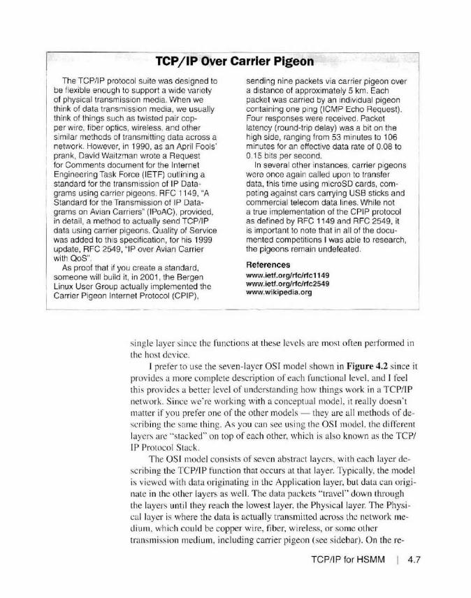
TCP /IP Over Carrier Pigeon
The TCP/I P protocol suite was designed to be flexible enough to support a wide variety of physical transmission media. When we think of data transmission media, we usually think of things such as twisted pair cop-per wire, fiber optics, wireless. and other similar methods of transmitting data across a
1 network. However, in 1990, as an Apri l Fools'
1 prank, David Waitzman wrote a Request for Comments document for the Internet Engineering Task Force (IETF) outl ining a standard for the transmission of IP Datagrams using carrier pigeons. RFC 1149, "A Standard for the Transmission of IP Datagrams on Avian Carriers" (IPoAC), provided, in detail, a method to actually send TCP/IP data using carrier pigeons. Quality of Service was added to th is specification, for his 1999 update, RFC 2549, "IP over Avian Carrier with QoS".
As proof that if you create a standard, someone will build it, in 2001 , the Bergen Linux User Group actually implemented the Carrier Pigeon Internet Protocol (CPIP),
sending nine packets via carrier pigeon over a distance of approximately 5 km. Each packet was carried by an individual pigeon containing one ping (ICMP Echo Request) . Four responses were received. Packet latency (round-trip delay) was a bit on the high side, ranging from 53 minutes to 106 minutes for an effective data rate of 0.08 to 0.15 bits per second.
In several other instances, carrier pigeons were once again called upon to transfer data, this time using microSD cards, competing against cars carrying USB sticks and commercial telecom data lines. While not a true implementation of the CPIP protocol as defined by RFC 1149 and RFC 2549, it is important to note that in all of the documented competitions I was able to research, the pigeons remain undefeated.
References www.ietf.org/rfc/rfc1149 www.ietf.org/rfc/rfc2549 www.wikipedia.org
sing le layer since the functions at these levels are most often performed in the host dev ice.
I prefer to use the seven-layer OSI model shown in Figure 4.2 s ince it provides a more complete description of each functional level. and I feel th is provides a better level o f understanding how things work in a TCP/IP network. Since we're working with a conceptual model. it really doesn' t matter if you prefer one of the other models - they are all methods of describing the same thing. As you can see using the OS I model, the d ifferent layers arc ' 'stacked" on top o f each other, which is a lso known as the TCP/ IP Protocol Stack.
The OSI model consists of seven abstract layers, with each layer describing the TCP/IP function that occurs at that layer. Typically, the model is viewed with data o riginating in the Application layer, but data can originate in the other layers as well. The data packets "travel" down throug h the layers until they reach the lowest layer, the Physical layer. The Physical layer is where the data is actually transmitted across the netwo rk medium, which cou ld be copper wire, fiber, wireless, or some o ther transmission medium. including can-ier pigeon (see s idebar). On the re-
TCP/IP for HSMM I 4.7

OSI Layer Function Data Type Examples
7 - Application Applications HTIP, FTP. Streaming Media
Translation. encryption, data 6 - Presentation compression. character Data HTML GIF. CSS
encoding
5 - Session Managing communication
RPC. SSL, SOL sessions
4 - Transport Reliable transmission of data Segments/Datagram TCP. UDP, NETBEUI
segments
3- Network Addressing, routing, traffic Packet 1Pv4, 1Pv6, IPsec, ICMP control
2 - Data Link Reliable transmission of data
Frame PPP, IEEE 802.2, L2TP,
frames MAC, LLDP
Transmission and reception of Ethernet physical layer, DSL, 1 - Physical raw bit streams over a Bit USB, ISDN physical medium
Figure 4.2 - The OSI model.
4.8 Chapter 4
ceiving end. the data proceeds ··up .. through the layers. eventually reaching the destination layer.
Layer 7 - The Application Layer Layer 7, or the Application Layer. is where the data is usually (but
not always) generated. Since the OSI model is an abstract conceptual model, nothing is w1i tten in stone and some o f the functions can be performed at other levels, but it' s far easier to follow the path of the data packet if we stick to the normal path of data now. This data could be a request from your web browser to view a page from a web server, transfer a file, send an e-mai l message, and so o n.
Layer 6 - The Presentation Layer Layer 6. the Presentation layer translates between d ifferent character
encoding schemes. encrypts and decrypts data, and in general ensures that data from the sending host is in a format readahle by the receiving host. In some TCP/ IP protocol stack models. the Application and Presentation layers are combined and viewed as a sing le layer.
Layer 5 - The Session Layer The Session layer is responsible for opening, closing, and managing
sessions, forming a semi-permanent dialogue between the Application layers on the communicating hosts. As part of managing sessions, the Session layer also handles session recovery, in the event that an active session disconnects or times out. The Session layer also handles authentication and authori zation between hosts.
In some of the TCP/IP models, the Session, Presentation, and Application layers are combined into a single " Host" layer, since much of the functionality of chese layers is often handled directly by the application software itself.
Layer 4 - The Transport Layer The Transport layer is where data movement between hosts really be
gins to occur. It is at this level that the Transmission Control Protocol (TCP), and User Data Protocols (UDP) are impleme nted.
With the TCP protocol, the Transport layer is responsible for ensuring that received packets are reassembled in the proper order, ensuri ng reliabili ty and fl ow control. The TCP protocol is designed to ensure error- free transmission of daca. It does this by requesting the retransmission of Jost data packets, implementing flow control to ensure that the data fl ows chrough the network as smoothly as possible, as well as congestion avoidance to prevent overloading the data circuit. Because multiple packets can be sent by the sending host and some dropped along the way, requiring retransmission of the missing data, the packets may be received out of order and must be reassembled in the proper order before sending the data up to the Application layer. TCP is used for web browser connections, file transfers, and other data communications that require error-free data transfers.
User Data Protocol (UDP) is also known as Unreliable Data Protocol because it's j ust that, unreliable. There is no guarantee that the data will be error-free and that the packets are in the correct order. Data is sent just once from the sending host and passed by the receiving host up to the Appl ication layer as the packets are received. There is no method for retransmission of lost packets or veri fying that the packets are in the right order in UDP.
This may seem like something we wouldn ' t want to happen. sending data to an application that may be missing pieces. However. UDP is faster than TCP, and is often used for real-time voice and video transmission where speed is of the essence. If some of the data is lost, it's not all that impo1t ant. You really don' t want a video to have to stop and wait for some mi ssing packets - you want it to be a continuous data stream. This is why, when you're watching a video or li stening to music across the Internet, sometimes the video or audio cuts in and out or stuuers. The missing data packets are ignored and what you 're seeing or hearing are the packets that made it though.
TCP/IP for HSMM I 4.9

4.10 Chapter 4
Layer 3 - The Network Layer The Network layer is often referred to just as '"Layer 3." Thi s OSI
model layer is where a ll of the network addressing and routing occurs. IP addressing is added lo the data packet and is used for host identification and packet forwardi ng . Automatic routing protocols such as the Routing Informatio n Protocol (R IP and RIPv2) and Open Shortest Path First (OSPF) are also implemented at the Netwo rk layer. We'll get more into the deta il of routing protocols in j ust a bit. as they are a key component in implementing Amateur Rad io HS MM networks.
At the Network layer. we 're sta rting to get into the actual networking dev ices, such as switches and routers. Often, you will hear a switch referred to as a Layer 2 or Layer 3 switch. Thi s refers to the capabilities of the switch. In the case o f a Layer 3 switch. the switch is capable of perform ing both the Layer 2 packet switching and the Layer 3 routing functions. able to function as both a switch and a router. Layer 3 uses IP addresses to transfer data between the network devices.
Layer 2 - The Data Link Layer
The Data Link layer is a lso known j ust as "Layer 2." This is the layer where packet switching occurs. The Data Lin k layer is used for local delivery of packet frames across the local area ne twork (LAN). The Data Link layer is respons ible for the functional and procedural means to transfer data between network devices and also can provide LAN error detection and correction.
You will note that the Data Link layer mainly deals with the LAN , for data that leaves the LAN must be handled by the Network layer and a Layer 3 device such as a router. While devices on the external side of your network (such as DSL and cable modems) can use MAC addresses, often they use other data link protocols to move the data between devices. Since we're pri marily focusing on how all this works with an Amateur Radio HSMM network. we won' t concern o urselves w ith these other Data Link protocols since they' re generally handled for you by your Internet Service Provider and the Interne t.
The Data Link layer uses Media Access Control (MAC) addresses to transfer the frames of data. as compared to IP addresses used by the Network layer. A MAC address i. a 48-bit hardware address that is unique to a network device o r interface. Theoretically, there is only one device in the world with a particular MAC address. This is no longer an absolute. since some MAC addresses are stored in fi rmware and not actually permanently stored in the ne twork device hardware or read-only memory (ROM) as it was in the past. Certain devices all ow you to change the MAC address as pa11 of the device setup procedure. However, for all intents. you can con-

IP Addressing
sider a device 's MAC address to be unique on your LAN. Since MAC addresses are used only on the LAN and are not passed by routers and other Layer 3 devices, as long as every network device on your LAN has a unique MAC address. everything will work properly.
Layer 1-The Physical Layer And finall y. the Physical layer consists o f the basic networking hard
ware for transmission of data. The Physical layer converts data packets into the raw bits that go out over the network and vice versa. The Physical layer is responsible for converting the data bits in to the actual signals that go out across the transmission medium. whether it is the electrical signals used in the copper wi res in an Ethernet cable. the light used in a fiber optic cable. the radio signals used in WiFi. or any other method of transmitting the data. In the carrier pigeon example ment ioned earlier. the carrier pigeon would represent the physical layer of the data transmission.
OSI Model Summary So why is thi s abstract model so important if it's j ust a conceptual and
not an absolute representation of the packet fl ow in your network? Using the OSI model helps you visualize the complete data fl ow through your HSMM network. and will help you when troubleshooting any issues that you may have.
Many of the TCP/JP models lu mp the Transport. Session. Presentation. and Application layers in to a single layer. T he fu nctions in these layers are generally handled by software on the host. primaril y a server or workstation. Any problems you encounter involving these layers is usually a software application issue and not a hardware or networking issue.
For HSMM networks. and networks in general. we deal primari ly wi th the first three layers - Physical. Data Link. and Network. These are the layers that involve the actual routing and switching of the data packets or the physical hardware itself. Thi s is where we can expect most problems to occur. By understand ing the functi on of each layer. we can tailor our troubleshooting methods to help locate the area where the problem may be. Once we know what layer the problem may be occurring in. we can determine if we ·re dealing with a hardware or software issue and decide what steps to take to further identify and resolve the problem. We 'l l discuss some troubleshooting tools and techniques later in this chapter.
Have you ever wondered what those numbers in an IP address mean? When you look at the status of the network adapter on your PC as shown in Figure 4.3. you ' II see things such as IPv4 address 192. 168. 1. I 0. 1Pv4
TCP/IP for HSMM I 4.11

Network Connection Details IEI subnet mask 255.255.255.0, and IPv4 default gateway 192.168. 1. 1. There's a lot of other information on that status screen that we' ll need to know later. but for now we' ll just focus on the 1Pv4 information.
Netwod< Comedion !letals: I - ·1 Property Value "'
Connect1on--specl1c OM ... Oe:s:c:nption Realtek PCle GBE fomift Ccctrolle< PhysiCcl Pddress fB·OF·•1·D1-DA-75 Dl-CP Enabled Yes IPvt M<tess 10 2•2 255 23
llffelitti'~ •!:t-}!~jjf.: IM
You' ll also notice that the addressing information shown in Figure 4.3 doesn't use IP address numbers that you'd normally expect to see in a home network. That's because I have my home network configured to mirror the training lab network at work so l can set up and test things in my home lab before I do a live training class in front or real people. It 's a whole lot less embarrassi ng when everythi ng is set up ahead of time and stands a chance of working during the class.
Lease Obtaned Tuesday. December 2S. 2015 7·12-(l< lease Expires We<*iesday. December 30. 2015 i 1; 1Pv4 DetaUI Gateway 10 242 255 1 1Pv4 DflCP Server 10.242 255 1 IPvt DNS Se<Veo; 8.8.8.8
I IPv< WINS ~er 10 2•2.255 1
1 Net BIOS over Tcpip En. Yes Link-ioc.>l IP..·6 .A.ddress leBO 6c61 SJ12bb01tcta'.,J 1Pv6 Oef•ul Gateway v I - --< )
- -- -----
Qose -
Figure 4.3 -The PC network status screen.
Hopefully. by the time we fini sh this section, you ' II understand the differences between this and a typi cal "default'' home network confi guration. This will also help you understand the addressing scheme when you go co setcing
4.12 Chapter 4
up your HSMM network, as it also uses a different range of IP addresses than you may be used to seeing on your home network.
What the Numbers Mean An 1Pv4 address consists of four sets of numbers, separated by a deci
mal point. such as the 10.242.255.23 address shown in Figure 4.3. This form of nocati on is known as the ·'dotted decimal' ' method to show an IPv4 IP address. Thi s is actually a 32-bi t number chat is broken ur into 4 "octecs, .. each containing 2 bytes (8 bits) of information. This makes it a whole lot easier to read and understand than the real binary IP address of
0000 I 0101 1 I 1 00 I 01 I 1 I l 1 I 1000 I 0 I I I or
OA-F2-FF-1 7 in hexadecimal.
It is important to remember that every bi t of an IP address has significance. If you keep in mind that you arc actually working wi th a binary or hexadecimal number. when you get to things like subnetting and subnet masks, it's a lot easier to see how all the pieces fit together.
This 32-bit address gives us a total of 4.294,967,296 (232 ) unique IP addresses. An IP address actually contai ns two separate pieces of information: a network number and a host number. The separation point between the network portion of an lP address and che host portion of the address is

user-selectable and is performed with the subnet mask. IP subnetting is one of the more difficult things about IP addressing and routing to understand and work with. We'll cover subnetting and subnet masks in a bit, but for now, all you need to know is that an IP address contains both a network number and a host number.
1Pv6 addressing is a whole different critter, using a 128-bit address and would take an entire book all by itself to discuss. Fortunately for us, just about everything we use in Amateur Radio HSMM networking and in our ham shack network uses !Pv4 and will continue to do so for quite some time, so we'll be fine if we stick lo just talking about !Pv4.
IP Address Classes The 1Pv4 addressing range is broken out into five address ranges, also
known as classes. and within those classes, there are some special addresses that are handl ed differently than the other addresses. Figure 4.4 shows the 1Pv4 address classes. The address classes in normal use are Class A, B, and C. Class D is reserved for multicasti ng and Class Eis reserved for experimentation. Class A addresses 127.0.0.0 to 127.255.255.255 are reserved for loopback and diagnostic functions. You can also modify the subnet from the default for the IP class and change the number of networks and hosts around as needed. We' ll discuss this more when we talk about subnets and subnetting.
Public versus Private IP Addresses You may have run across the terms public and private IP addresses.
Public IP addresses are simply IP addresses that can be accessed directly from the ' 'global" or "public" Internet. Within each IP class, there is a range of addresses reserved for private IP addresses. A list of these private IP addresses is shown in Figure 4.5.
Private IP addresses are valid IP addresses, hut are not mutable
Class 1•1 Octet High Order
Number of Networks Usable Host
Decimal Range Address Bits Addresses
A 1 -126 0 126 16,777,214
B 128 - 191 10 16,382 65,534
c 192 - 223 110 2,097, 150 254
D 224- 239 1110 Reserved for Multicasting
E 240 - 254 1111 Experimental - Used for Research
Figure 4.4 - The 1Pv4 address classes.
TCP/IP for HSMM I 4.13
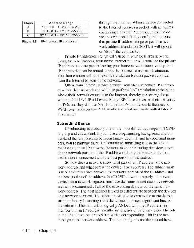
Class A B c
Address Ran!:le 10.0.0.0 - 10.255.255.255
172.16.0.0 - 172.31.255.255 192.168.0.0 - 192.168.255.255
through the Internet. When a device connec ted to the Internet receives a packet w ith an address containing a private IP address, unless the device has been specitica lly configured to route
Figure 4.5-1Pv4 private IP addresses. that private IP address range or perform net
vvork address translation (NAT ). it w ill ignore, or "drop." the data packet.
4.14 Chapter 4
Private IP addresses arc typically used in your local area network. Using the NAT process, your home Internet router wi ll translate the private
IP address in a data packet leaving your home network into a valid pub lic IP address that can be routed across the Internet to its final destination.
Your home router will do the same translation for data packe ts coming from the Internet to your home network.
Often. your Internet service provider will also use private IP addresses within the ir network and will also perform NAT trans lation at the point where their network connects to the Internet, the reby conserving those scarce public 1Pv4 IP addresses. Many ISPs have conver1ed their networks to IPv6. but they still use NAT to provide IPv4 addresses to their users. We ·11 cover more on how NAT works and what we can do wi th it later in
this chapter.
Subnetting Basics IP subnetting is probably one of the most difficult concepts in TCP/IP
to grasp and understand. If you have a programming background and understand the re lationships between binary. decimal, and hexadecimal numbers, you're halfway there. Unfortunately, subnetting is also the key to routing data in an IP network. Routers make their routi ng decisions based
on the network portion of the IP address and only the router at the final destination is concerned with the host portion of the address.
So how does a network know what part of an IP address is the network address and what part is the device (host ) address? The subnet mask is used to cli ffcrentiate between the network port ion of the IP address and the host portion of the address. For TCP/IP to work properl y, all ne twork devices on a network segment must use the same subnet mask. A network segment is comprised of all of the networking devices on the same ne twork address. The host address is used to d ifferentiate between the devices on a network segment. T he subnet mask. also known as the netmask. is a string of binary l s starting from the leftmost. or most significant bits, of the netmask. The netmask is logically ANDed with the IP address (rememher that an IP address is really just a series of 32 binary bits) . The bits in the IP address that are ANDed with a corresponding I bit in the nctmask yield the network address . The remaining b its are the host address.

IP Addressing
192.168.1.25
255.255.255.0
IP Address
Subnet Mask
Figure 4.6 shows an example of how this looks using the dotted decimal method of representing IP addresses.
Subnetting can be confusing when you try to think or it in terms of a decimal JP address since the I s and Os in a decimal number aren't read il y apparent. When you break the IP address down to the binary level. the rela tionship be-
192.168.1.0 Ne•work Add•ess comes much more understandable . Figure 4.7 shows how
.25 Ho>tAd tt. m all the bits in an IP address are used lo de rive the ne twork ~----------~I and host portions of a given IP address. Figure 4.6 - Determining the network address and host address of an IP address.
When you're working wi th the default netmask for the IP address cl ass you're using. the calculation is fa irly easy. The numbers in the IP address that match up with a corre-
sponding 255 in the netmask form the network address . The numbers in the IP address that match up with a 0 in the netmask form the
host address. In the example in Figure 4.6, you can see that the 192.168.1 portion of the JP address matches up with the 255.255 .255 port ion o f the netrnask, therefore the network address will be 192.168. 1.0.
The reason the network address ends in 0 is because logica lly ANDing the IP address with the 0 in the netmask results in a 0. In an IP address, there are two host addresses that cannot be used for device addresses. The 0 address is used to represent the network address, and the "a l I one's" ad
d ress for the specific network address is used for the network broadcast address. We ·11 explain how the network devices use the broadcast address when we talk about packet switching and MAC addresses in a bit.
IP Addressing in Binary
11000000 10101000 00000001 00011001 IP Add ress
111111111111111111111111 00000000 Su bnet Mask
I I I~ Network Address Host Address
11000000 110101000 I 00000001 I 00000000 00011001
192 168 1 0 .25
Figure 4.7 - The binary method of determining the network and host addresses.
TCP/IP for HSMM 4.15

Tn the example shown in Figure 4.6, the broadcast address wo uld be
l 92.168.1.25 5, so you will not be able to assign a dev ice to that address . The reason why you speci fy the "all one's" address and not just use 255 as the host add ress for the broadcast address is that ne tmasks are not requ ired to match up with the decimal digits in an TP address. This is known as a variable leng th subnet mask (YLSM) and is used to subdivide a single net"''ork into smaller subnets that you may need. This may result in your network add ress using some of the bits in an octet and your host address will use the remaining bits in that same octet. making it vi rtua lly impossible to dete rmine the network address and host address range by simply looking at a deci ma] number.
It a ll becomes clear when you break it down to the indiv id ual bits
as to \Vhich part of the octet i~ the network and which part is the host, but it's so much easie r to read the decimal and it's a pain to break it down
into bits. T here are plenty of on line subnet mask calculators to help you do thi s if you find yourse lf in a si tuation where you need to work w ith variable length subnet masks. I have found tha t www.subnetmask.info has several IP address and subne t calculation tools that you will find very handy as you start working more with TP addressing and subne tting. A list of the possible variable length subnet mask se ttings is prov ided in IETF RFC I 878, which can be fo und at www.ietf.org/rfc/rfc1878
I ? 1<l: CtQJ \\-'1.fl
IP . .;.d.h~ z 10 4~ ; ~1':.n
~: ~1rr_a$k :s~ Ho
-LAN
1·_,,:1 r_.,ny_~~:!:_:ir.
! H.~;t,_.u...:.:L.::s..1.~:;.~
J'. .l:H'A' "! •:i •••••
:...011fode 5 1·os1 0 1·1w .::-::. I ?"·"~"' ? Adcir!IS :•J ]1'( i~d 1·1 '. :>NS ·
· i.;tlS 2
\ \ . ..\..'\; (.ll(P
a ~rn 9
.-1
I
,, An'""" '"""~ v
Tx :F·ow ~; l~ .;8M v
~)\OU .. '\C e (\
~
Figure 4.8 - The BBHN basic setup screen showing the WiFi and LAN IP addresses.
4.16 Chapter 4

and shown in a chart in the next section. Now let" s make this whole subnctting thing even more fun. In I 993,
as part of an effo1t to help conserve the rapid exhaustion of IPv4 addresses, the IETF introduced Classless Inter-Domain Routing (CIDR) in RFC I 518 and RFC I 519, which introduced the concept of YLSM. Along with the introduction of CIDR, a new method of subnet notation was also in troduced. The CIDR notation for an IP address allows you to see both the IP address and its associated subnet mask in a combined representation. rather than having the TP address and the subnet mask shown separately. The CIDR notation shows the IP address. followed by a slash (/) and the number of bits in the subnet mask (starting from the leftmost. or most significant bit). In this way, an JP address such as 192.168. 1.23 that uses a subnet mask of 255.255.255 .0 can now be represented as 192. 168.1.23/24. This notation further helps you determine the network address and host address by reinforcing the fact that an IP address is made up of binary bits, so the /24 would help serve as a reminder that an IP address is reall y a 32-bit binary number and that 24 bits arc used for the network number and the other 8 bits are the host address.
Why Mess With The Subnet Mask? By using variable length subnet masks. we can create multiple sub
nets from a single IP address range. One important rule of IP addressing is that each network segment has to be on its own network number. For example, in the case of my BBHN node (see Figure 4.8), the node addresses for the WiFi Network interface are in the I 0.0.0.0 network with the default Class A net mask of 255.0.0.0 With this subnet addressing scheme. 16, 777 ,2 14 host addresses are avai I able for node addresses. all of them on the same network. which is fi ne for the wireless mesh side of things . However, on the LAN side, since we have only the options of I. 5. or 13 HostDirect addresses available in the firm ware, it would be wasteful to use up a large chunk of IP addresses we can' t use. This is where vari able length subnet masks come into pl ay. In the 5 Host Direct mode, the available LAN IP addresses on my BBH N node are in the 10.100. 153. 144 network, with a subnet mask of 255.255 .255.248, or 129 in CIDR notati on.
Looking at the VLSM chart in Figure 4.9. you can see that this subnet mask provides for six usable host addresses on the LAN network segment. It also allows for an addi tional 31 networks to use the I 0. 100.1 53.x address range for use in other nodes. This is how YLSM can be used to conserve IP addresses. Since we only need five host addresses on the LAN side of the typi cal BBHN node, by using the /29 subnet mask, we only consume eight addresses (s ix usable host addresses) in the BBHN network addressing scheme.
TCP/IP for HSMM 4.1 7

CIDR Netmask #of IP #of Hosts #of Addresses Networks
10 0 .0.0.0 4,294,967,296 4,294,967,294 1 /1 128.0.0.0 2,147,483,648 2, 147,483,646 2 /2 192.0.0.0 107,374,182 107,374, 180 4 13 224.0.0.0 536,870,912 536,870,910 8 14 240.0.0.0 268,435 ,456 268,435,454 16 /5 248.0.0.0 134,217,728 134,217,726 32 /6 252.0 0.0 67, 108,864 67,108,862 64 17 254.0.0.0 33,554,432 33,554,430 128 /8 255.0.0.0 16,777,216 16,777,214 256 19 255.128.0.0 8,388,608 8,388,606 512 /10 255.192.0.0 4, 194,304 4, 194,302 1024 / 11 255.224.0.0 2,097, 152 2,097 ,150 2048 /12 255.240.0.0 1,048,576 1,048,574 4096 /13 255.248.0.0 524,288 524,286 8192 /14 255.252.0.0 262,144 262,142 16,384 /15 255.254.0.0 131 ,072 131,072 32,768 /16 255.255.0.0 65,536 65,534 65,536 /17 255.255.128.0 32,768 32,766 131 ,072 /18 255.255.192.0 16,384 16,382 262, 144 /19 255 255.224.0 8,192 8,190 524,288 120 255.255.240.0 4,096 4,094 1,048,576 /21 255.255.248 .0 2,048 2,046 2,097,152 122 255.255.252.0 1,024 1,022 4, 194,304 123 255.255.254.0 512 510 8,388,608 124 255.255.255.0 256 254 16,777 ,216 /25 255.255.255.128 128 126 33,554,432 /26 255 255 255 .1 92 64 62 67,108,864 /27 255.255.255.224 32 30 134,217,728 128 255.255.255.240 16 14 268,435,456 /29 255.255.255.248 8 6 536,870,912 130 255.255.255.252 4 2 107,374,182 /31 255.255.255.254 2 0 2, 14 7,483,648 /32 255.255.255.255 1 0 4,294,967,296
Figure 4.9 - Variable length subnet mask chart.
4.18 Chapter 4
Herc is where th ings get messy when you try to figu re out the network number for the network segment. Remember. we're really dealing with a binary number, and in this example. the subnet mask takes up only a portion or the last octet.
Here ·s the method I use to determine the actual network number in cases like this. First, determine the tota l number o f IP addresses allowed by the subne t mask, in this case eight, keeping in mind that the network number and the broadcast address are not available for host use, which is why vve on ly have six addresses availab le for hosts.
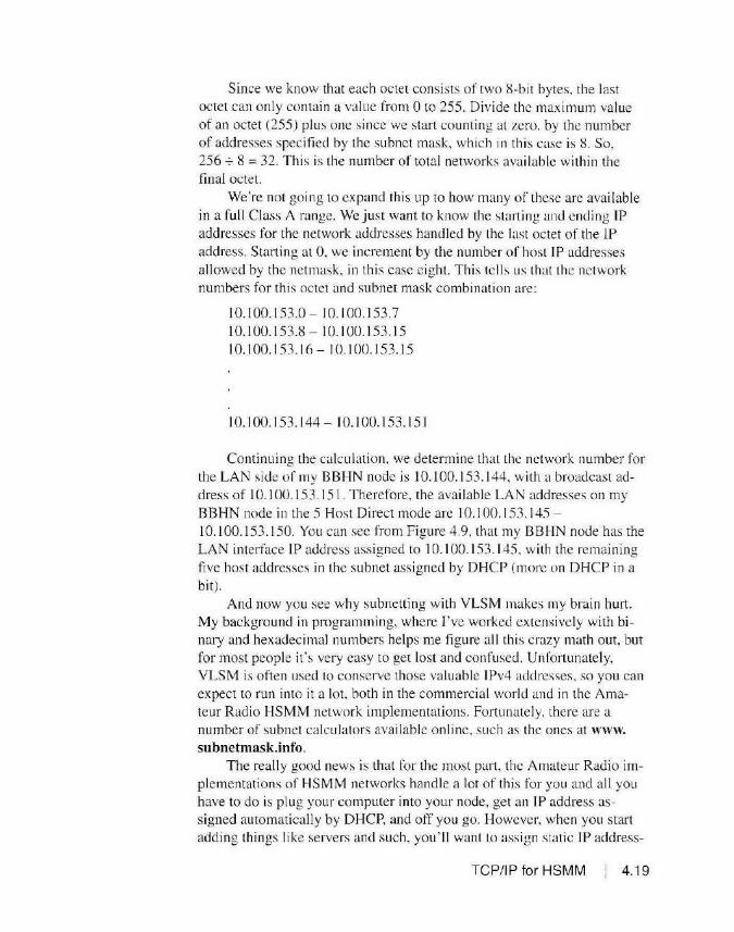
Since we know that each octet consists of two 8-bit bytes. the last octet can only contain a value from 0 to 255. Divide the maximum value of an octet (255) plus one since we start counting al zero. by the number of addresses specified by the subnet mask, which in this case is 8. So. 256-:- 8 = 32. This is the number of total networks available within the final octet.
We're not going to expand this up to how many of these are available in a full Class A range. We just want to know the starting and ending IP addresses for the network addresses handled by the last octet of the IP address. Starting at 0, we increment by the number of host IP addresses allowed by the netmask, in this case eight. This tells us that the network numbers for this octet and subnet mask combination are:
10.100.153.0- 10.100.153.7 10.100.153.8-10.100.153. 15 10.100.153.16-10.100.153.15
10.100.153.144- 10.100.153.151
Continuing the calculation, we determine that the network number for the LAN side of my BBHN node is 10.100.153.144, with a broadcast address of l O. l 00.153.151. Therefore, the available LAN addresses on my BBHN node in the 5 Host Direct mode arc I 0.100.153.145 -10.100.153.150. You can see from Figure 4.9, that my BBHN node has the LAN interface IP address assigned to IO. l 00.153 .1 45. with the remaining five host addresses in the subnet assigned by DHCP (more on DHCP in a bit).
And now you see why subnetting with VLSM makes my brain hurt. My background in programming, where I've worked extensively with binary and hexadecimal numbers helps me figure all this crazy math out, but for most people it 's very easy to get lost and confused. Unfortunately, VLSM is often used to conserve those valuable 1Pv4 addresses, so you can expect to run into it a lot. both in the commercial world and in the Amateur Radio HSMM network implementations. Fonunately. there are a number of subnet calculators available on line, such as the ones at www. subnetmask.info.
The really good news is that for the most part, the Amateur Radio implementations of HSMM networks handle a lot of this for you and al l you have to do is plug your computer into your node, get an IP address assigned automatically by DHCP, and off you go. However, when you start adding things like servers and such, you ' ll want to assign static IP address-
TCP/IP for HSMM 4.19

es rather than use DHCP. so you'll need to know what addresses you can use on your local network for these devices. We' ll talk more about static IP addresses and DHCP in just a bit.
MAC Addresses and Switching
4.20 Chapter 4
Here is one of those places where we have to step back a bit and talk about switching and MAC addresses before we can get into IP routing and routing protocols. Now that we have seen the OS I model and how data flows through a network. and how the IP address of a device is used to access hosts across the Internet, we have to look at how traffic flows on our local network (LAN). There is a close relationship between switching, which uses MAC addresses to tran sfer data, and routing, which uses IP addresses to transfer data.
Before your data can get to the Internet, it has to use your LAN to get to the routing device. also known as the default gateway, which will evenlllally get the data to the Internet. This is how your computer automatical ly knows where to send data that needs to leave your LAN. Any IP address that is not in the network address range assigned lo your LAN is sent to the default gateway IP address for routing to the proper destination. This is all done using the destination IP address in the data packet. However, all of the devices on the same network segment use the MAC address of a data packet rather than the IP address to move the data between devices, including the defaul t gateway.
Looking back al Figure 4.3. the PC network connection details, you can see the physical (MAC) address of my computer's network interface is F8-0F-4 1-Dl -DA-75 and the ddault gateway for my network is l0.242 .255 .1. Usually. the default gateway JP address is assigned to either the lowest or highest assignable host address in a network 's address range, hut that is not required, and the default gateway can be any valid host IP address on your network.
As we discussed earl ier. the MAC address is a 48-bit address stored in the hardware or firm ware of the network interface hardware. The first 24 bits are used to identi fy the manufacturer of the network interface and the last 24 bits form a unique number assigned by the manufacturer. While some network devices al low you to change the MAC address if it's stored in firmware, the MAC address is designed to be unique worldwide, and there will be only one device on your network with that MAC address. You can even look on line at sites such as www.coffer.com/mac_find to determine the manufacturer of the network interface device by providing the first six hexadecimal characters of the MAC address.
So why do we need MAC addresses if we 're ac tually using IP addresses to send our data·' Remember the OSI model we talked about ear-

lier? IP addresses operate at the Network layer and above. The Data Link
layer is what is used to transfer data between local hosts across the Physical layer.
To help avoid confusion, data packets at the local network level are known as "frames." As frames move through your network, all of the switches and routers listen for which port each source MAC address was heard on. It saves this information in a MAC address forwarding table, also known as a forwarding infonnation base (FIB) or content-addressable memory (CAM) table.
As frames move through the network, the switches and routers essentially build an internal map of where the data frames need to go next. When a host needs to send a frame of data, if it does not already know the MAC address of the receiving device it will send a network broadcast message
using the Address Resolution Protocol (ARP) to find out where to send the data. The sending host will use ARP to broadcast ''Who has IP address 10.242.255.70?" if it needs to send data to my network printer, for example. The printer will respond to the ARP request with its MAC address.
All of the network devices such as switches and hubs within the path
between the two devices will save this information in the ir local MAC forwarding and ARP tables and then forward the response to the device that made the ARP ''request." An ARP table is simply a li st of the MAC addresses and their associated IP addresses that have been "heard" on the LAN. This information will also be stored in the original sending host's ARP table so that it won't need to ask again how to get to the requested device, thereby reducing network traffic. The information in the MAC forwarding and ARP tables will be "aged-out" or deleted after a certain time period. This time period varies between network devices, but typically
ranges from 15 seconds to 4 hours. For data that is leaving your LAN, since the Network layer has al
ready determined that the destination IP address is not on your LAN, it will send the frame to the 1Pv4 default gateway. As before, if the sending device does not already know the MAC address of the default gateway, it will use ARP to locate the MAC address of the default gateway, w hich is at IP address 10.242 .255. I in the case of my network. As the data moves between devices. the source and destination IP addresses are unchanged unless network address translation (NAT) is in use. We'll talk more on NAT in a bit.
The source and destination MAC addresses change as the data frames move across the network because routers operate al Layer 3, the Network layer, and do not forward Layer 2 frames. Instead, they route and then regenerate the data frame to transfer the data to the next network segment. This is done to keep all of your LAN traffic , such as ARP and other Layer 2
TCP/IP fo r HSMM I 4.21

4.22 Chapter 4
traffic. from clogging the Internet with unnecessary and unusable data. You will often hear these Layer 2 network segments referred to as "broadcast domains." Since routers do not route Layer 2 broadcast traffic , each network segment becomes its own Layer 2 island, or broadcast domain.
At the LAN level, we also need to discuss the distinction between hubs and switches. While Ethernet hubs are rapidly fading into disuse, at the wireless level the hub concept is back in play because the data is typically transmitted over a single RF channel shared by a ll of the nodes on the RF network. We'll explain how the hub concept applies to RF in a bit, but it important to know the difference between hubs, switches, and routers as we build out our HSMM networks.
Jn an Ethernet ne twork, hubs operate at the OSI model Physical layer (Layer I). Any data frames received on one port arc transmitted out all of the other ports on the hub. This means that only one hub-connected device at a time can transmit data, which can result in frame collisions, requiring that the data be retransmitted when such collisions occur. The devices that can be affected by these frame collisions are in an area known as a "collision domain." Therefore. all network devices that are attached to a hub are said to be in the same collision domain and must wail their tum to transmit data.
Switches operate at Layer 2 of the OST mode l, using the MAC addresses in the data frames to forward the frame out the correct p011. This allows all of the other ports on the switch to transmit and receive data independently, w ithout worry of collisions. This means that each individual switch port is in its own collision domain. and as such, can transfer data at maximum throughput through the switch. Any frames that would ordinaril y collide by needing the same output switch po rt at the same time will instead be buffered within the switch, to be sent later without any collisions occurring .
It is important to note that you can only have one active path to a device on your LAN. If you have more than one path. you have what is commonly known as a ''switch loop." Since switches store the MAC addresses internally, they get confused if they hear the same MAC address on two different po11s and start constantly updating their MAC address tables. Essenti ally this creates a "broadcast storm" as the confused switch starts to flood your ne twork with packets.
Some switches, a lso known as "managed" switches, implement the Spanning Tree Protocol to allow you to have redundant paths to a device without creating a switch loop. Without going into a lot of detail, the Spanning Tree Protocol w ill determine the best path to a device and shut down the other switch ports that have a path to the device. If the primary path fails, Spanning Tree will detennine the next best path to the device
and enable the desired port. Since o ur ne tworks are generally small and there is li ttle need for re
dundant switch paths. we don "t need to worry about the need for Spanning Tree . However, there are many o ther benefits to using m anaged switches, primaril y the abili ty to remotely manage and moni tor the switch as well as the abili ty to implement virtual loca l area ne tworks (VLANs) . We'll talk mo re about VLA Ns in a bit. Managed switches usually cost more than unmanaged switches, so at this point it beco mes a matter of personal preference or the need for remote management and VLANs that will help you dec ide which you need.
As you can sec. there "s a lot going on just to send your data around your LAN and to the Inte rnet. It's important that we know how the data moves across the various network segments as we build and troubleshoot HSMM networks. As r ve mentioned earlier, there are entire books devoted to routing and switching. so don·t feel bad if you feel like you're trying to drink fro m a ti re hose. because for all intents. you arc . This is a lot of material lo absorb at one sitt ing. The good news is that things do get easier the more you work with TCP/IP. If it's any consolatio n. J" ve been working with TCP/IP for over 20 years. have been taught by some of the best in the business, and I sti ll get my brain wrapped up in circles over some of this stuff.
IP Routing and Routing Protocols O ne o f the thi ngs that has always amazed me about TCP/IP is how
the data seems to automatically know w here it needs to go. T hi s is espec ia lly true when you get to the ac tual routing part of TCP/IP. W hether the destination is just o ne router "hop" away, or dozens, the data ge ts to its destination and back wi tho ut getting lost (usually) . This is all handled in Layer 3, the Network layer or OSI model. T he Network layer derives the network address fro m the destinati on lP address us ing the subnet mask. Ro uting decisions arc based on whether the network is local, a remote known network, o r an unknown network destination.
We' ll start w ith the unknown dest inat ions, since that is actually an easy routing decisio n. Referri ng back to Figure 4 .3, you 'll see that my workstation has an 1Pv4 defaul t gateway of 10.242.255. l. All IP devices have a default gateway or a de fault route. T he IP address specified as the default gateway or default rou te is where the device sends data bound for destinations that are not o n the local network. and the device does not specifica ll y know how to get the data there.
As the packet moves th rough the net work, each device will route the data upstream. where eventually (hopefully) it reaches a router that does know the desti nation network and routes it accordingly. Since the data
TCP/IP for HSMM 4.23
4.24 Chapter 4
packet's .. time to Jive·· is decremented w ith each hop. the data will eventu
ally make it to the destination, or it will be dropped from the network if the destination cannot be found or the time to live expires. The time to live becomes very important if there is a routing eJTor in the ne twork and the data packets start bouncing back and forth between routers. This is known as a "routing loop." Eventually, the time to live will expire and the packets wi I I be discarded by the routers. Of course, this also means that as Jong as
the routing error exists, no data will get past the routing loop.
Static and Dynamic Routes IP routes are stored in each Layer 3 network device in what is com
mon ly called a routing table. This table is a list of all known routes, including locally attached networks and the default route. If you are running a routing protocol, such as RIPv2 or OSPF (discussed below), the routes in
the table may change as new routes are discovered and routes that no longer exist a re removed.
Routers use static and dynamic routes to make their routing decisions. A static route is a manual entry used to specify exactly where lo send the data for a specific destination or destinations. While not really feasible to implement in a large netv.:ork. and defini tely not preferable in a constantly changing ne t1,vork such as a BBH N or AREDN network. static routes require far less processing by the routing engine in the router. They are deemed more secure since they cannot be altered by a routing protocol update. The downside to static routes is that you have to add them manually to each router's routing table, which can be very cumbersome, complex, and time consuming . Adding stati c redundant routes is a lso cumbersome and can quickly tum into a tangled mess.
Fortunately. here is where the power of dynamic routes comes into play. Dy namic routes are learned rou tes that are shared among routers e ither on a regular interval or when the topology o f the network changes.
For ex ample, at the point where your home interne t service provider (ISP) connects to the internet, their routers ty pically run the Ex te ri or Border Gateway Protocol (BGP) to exchange routing informati on w ith the route rs on the Internet itself. Internally, your ISP would most like ly run a protocol such as Inte rio r BGP. Open Sho rtest Path First (OSPF). o r Routing In fo rmation Protocol version 2 (R IPv2) . This removes the necessity fo r your ISP to create routing tables manually for new subscribers and external network route changes . D ynamic routing also allows for redundancy in the ne twork.
Since you can only have one active route to and from a destination, you can' t j ust add another path to the destination and call it good. In fact, having two or more routes to a dest ina tion can create a situation known as

·'asymmetrical routing." This is where the data takes one path to the J est ination and a different path back.
Depending on the type of data, asymmetrical routing can cause some strange issues. For example, the Secure Sockets Layer (SSL) protocol is designed to prevent what is known as "the man in middle" rorm or data breach. where a device is inserted in the path to extract the data fl ow ing o n the path. With asymmetrical routing, SSL may interpret this as such an attack and discard the suspect data packets .
In any event. it is always best to have only one acti ve routing path to and from the destination. This is most often an issue when using static routing and is dealt with automatically when using a dy namic routing protocol. Because of the dynamic nature of a routing protocol , as newer. better routes a re discovered. they are added to the routing tables o r the
routers. Older. less efticient routes are either dropped o r kept in the routing table as a redundant or backup route. The dynamic routing protocol ensures there is only one active routing path to and from the destination.
Types of Routing Protocols There are two basic types of routing protocols, distance-vector and
link-state. A distance-vector protocol will basically use the router "hop' ' count to de termine the fewest numbers of hops to get to a destination. Some versions, such as Cisco's Interior Gateway Routing Protocol (IGRP) and Enhanced Interior Gateway Routing Protocol (EIGRP) also incorporate speed. reliability, and other factors when determining the best path to a destination. Routing Information Protocol (RlP ), and its successor.
R!Pv2. use only the router hop count to determine the best path to a destination.
Routers running a distance-vector routing protocol will send updates containing a ll of the routes that they know to neighboring routers on a reg ular interval. typically every 30 seconds. These updates can be quite large and are considered to be less efficient than a link-state routing protocol. but in general. it is much easier to set up and use a distance-vec tor protocol such as R!Pv2.
Border Gateway Protocol (BGP) is described both as a path-vec tor
and a distance-vector protocol. For use in an Amateur Radio HSM M network. we don't need to confuse ourselves wi th the differences between a path-vector protocol and a distance-vector protoco l. One important thing to note is that BGP is also policy-based, meaning that rou ting decisions can also be made using manually created policies that can override normal routi ng based on information contained in the datagram. The routers o ut o n the Internet use BGP to share their routing information. You may run into the BG P protocol when configuring your Ham WAN implementation .
TCP/IP for HSMM 4.25

TCP/IP Ports
4.26 Chapter 4
Implementing and configuring the BGP routing p rotocol is well beyond the scope of this book and I recommend working with one of the HamWAN groups to assist you wi th sett ing it up.
With the exception of BGP. distance-vector routing protocols are becom ing less common and arc be ing replaced by the more efficient link
state routing protocols.
Link-State Routing Protocols Open Shortest Path First (OS PF ) and the Optimized Link State Routing
Protocol (OLSR) are known as link-state routing protocols. These protocols use a variety of factors. inc luding distance, link throughput , and re liabili ty to determine the best path. Rather than send updates every 30 seconds that contain all of the known routes, each router running a li nk-state rout ing protocol will only send updates to the ir ne ighboring route rs when a change in the ne twork topology occurs. such as when a link fail s or a better path is di scovered. This results in a fas te r route discovery process. known as "convergence.' ' and reduced routing information traffic on the network.
The BBHN and A REDN implementations use O LSR to maintain the routing tab les in each node on the network. As new nodes are discovered or nodes drop from the network, OLSR will automatically update the routing tables in a ll of the remaining nodes accordingly. T his is what gives the BBHN and AREDN HSMM networks their "self-discovery" and "selfhca ling'' capabilities. This is all handled automatically by the BBHN and
AR EDN firmware and there is no user configuration necessary. OSPF is considered to he the most common routing protocol used in
internal networks. OSPF also allows for secure routing protocol updates , he lpi ng to prevent routing table hacking attempts. A s with OLSR. OSPF uses distance, throughput , and rel iability when determining the best routes and w ill only send routing updates when there is a change in the ne twork topology. The HamWAN implementation uses the secure form of OSPF to manage the routing tables between c lient nodes and the cell site, as well as e ithe r OSPF or BGP between ce ll sites.
As with BGP, configuring and implementing OSPF is beyond the scope of th is book. If you are joining an existing Ham WAN network. they wi ll provide the setup information for the ir OSPF implementation as part of your cl ient node setup. If you are building out your own Ham WAN network. I recommend working with an exist ing Ham WAN group to assist you wi th setting up and configuring both OSPF and BGP.
Once again, it's time to skip around a bit and talk about TCP/IP ports. In addition to network and host IP addresses. TCP/IP a lso uses what are

Po rt
7
20
2 1
22
23
25
53
67
68
69
BO
110
123
143
161
179
194
264
389
443
445
520
636
Description
ICMP Echo Protocol
FTP Data Transfer
FTP Control
Secure Shell (SSH)
Telnet protocol
Simple Mail Transfer Protocol {SMTP)
Domain Name System (DNS)
Dynamic Host Configuration Protocol (DHCP) Server
Dynamic Host Configuration Protocol (DHCP) Client
Trivial File Transfer Protocol (TFTP)
Hypertext Transfer Protocol (HTTP)
Post Office Protocol v3 (POP3)
Network Time Protocol (NTP)
Internet Message Access Protocol (IMAP)
Simple Network Management Protocol (SNMP)
Border Gateway Protocol (BGP)
Internet Relay Chat {IRC)
Border Gateway Multicast Protocol (BGMP)
Lightweight Directory Access Protocol (LDAP)
Hypertext Transfer Protocol over TLS/SSL (HTTPS)
Microsoft Active Directory and W indows Shares
Routing Information Protocol (RIP)
Lightweight Directory Access Protocol over TLS/SSL
known as " ports" to move the data from the lower layers of the OSI model to the Appl ication layer for use by the various applications. Ports are numbered from 0 to 65535 , with the first I 023 ports designated as "system." o r "well -known" pons. An example of a well-known port is the port your web browser uses for the Hypertext Transfer Protocol (HTTP) to view a web page. Web servers typically " listen" for HTTP connection requests on TCP port number 80. Your browser wil l connect using an available port number above 1023 to send data to the web server on destination port number 80. The web server will respond back to the sending IP address and port with the web page information, which your web browser will then display on your screen. Figure 4.10 shows the more common well-known ports you can expect to use in your HSMM networks.
When you begin setting up servers on your HSMM network, you will need to know which ports you will need configured for the vari ous services you plan to offer on your network. While you can configure your application services on any port you choose, in general it is best to use the standard well-known or default ports for your applications to keep things simple. If you plan to use a firewall or network address translation (NAT, disc ussed below), you will also need to be aware of which ports
Figure 4.1 O - Well-known TCP/IP ports. you need to manage for your application
services to operate properly over your HSMM network. Again. by using the stan
dard or defau lt ports for your various applications and services, managing the firewalli ng and NAT portions is kept at a much simpler and less complex leve l.
Network Address Translation (NAT) Since only public Internet addresses are rou ted over the Internet, there
needs to be a method to rou te data from a private IP address-based net-
TCP/IP for HSMM 4.27
4.28 Chapter 4
work out over the Internet. Designed to help conserve the then-dwindling supply of public 1Pv4 addresses on the Internet, the Internet Engineering Task Force (TETF) defined the implementation of network address translation in RFC 1631. NAT allows you to map public IP addresses to private IP addresses and also provides for a means of private IP address-based networks to route their data over the Internet. By implementing NAT at the point where the private IP-addressed network meets the Internet, one or just a few public IP addresses can be used to service a large number of hosts on the private IP-addressed network. Your home Internet Service Provider (ISP) most likely uses NAT at the point where they tie to the Internet and then again at the point where your home Internet router/modem connects to your ISP.
When using NAT, as the data leaves the private IP-addressed network via the router at the default gateway IP address, NAT will modify the source address of the IP packet before forwarding it upstream. At the same time, the router will keep track of all of the active private to public IP sessions and mappings so that it knows where to send data coming back from the destination.
For data that originated on the public Internet side, the router implementing the NAT function must know where to send the incoming data on your private network. This is done by configuring port forwarding on the NAT router. There are several forms of NAT translation that can be used. The most common form is "one-to-many,,. where a single external IP address is mapped to multiple hosts in the private network. This is the form of NAT that is used in the BBHN and AREDN implementations if you enable the NAT feature.
On the router running NAT, you manually create forwarding rules based on the incoming destination port (or ports) on the external side. NAT will then forward the packets to the specified destination, such as a web server attached to your node. You can have multiple forwarding rules that forward the packets to multiple destinations. For example, you can have a web server listening on port 80 on one internal IP address, while you can have a separate FfP server listening on ports 20 and 2 1 on a different internal IP address. When a connection request comes in on the external side of the NAT router, it forwards the web traffic to the web server and the FTP traffic to the Ff P server.
Another form of NAT is the "one-to-one NAT' where any data received on the external IP address is forwarded to a single host on the internal private network. This is more commonly used in the commercial world, where the ISP provides a "block" of public IP addresses and each address is mapped to a separate host. The external interface on the router actually has multiple IP addresses configured, with NAT forwarding rules
created for each one-to-one mapping that is requi red. A side effect of implement ing NAT on your network is that it per
fon11S the most basic functions of a firewall. Devices on the external side of your network have no abi lity to access your private network except for those devices that have a NAT forwarding ru le. Since you know which internal devices will be accessible l"rom the outside, you can focus your security efforts on those devices without rea lly havi ng to worry that someone on the outside will access your network storage and delete your li l"e 's work.
The Downside of NAT NAT is not without its downside. Certain types of data do not play
nice with NAT translat ion. such as voice-over-IP (Vo IP) tranl c. Because of the way VoIP systems typically use the Sess ion Initiation Protocol (SIP), NAT breaks down since it may be trying to send the data to the VoIP call manager when it really means to send it to the IP phone itself and viceversa. There are methods avai lable to work around these issues, such as Session Traversal Utili ties for NAT (STU N), but this requires a separate STUN server in addit ion to the VoIP server and the IP phones.
Unless you have a need to implement NAT on your BBHN or AREDN network. it is best to use either the 1. 5. or 13 Host Direct mode. This gives each device on your local network an address that is di rectly accessible from other nodes on the same HSMM network wit hout the need fo r NAT.
Dynamic Host Configuration Protocol (DHCP) There are two methods of assigning an IP address to a device: static
and dynamic IP addressing. With static IP addressing. you manually assign the IP address to be used. along with the suhnet mask. default gateway, and DNS server information. Often. static IP addressi ng is used in conjunction wi th NAT and port forwarding to ensure that the device on the internal private network is permanently li xed at the correct address configured in the NAT forwarding rules. As a general ru le. static addressing should be al so used on all of your network devices such as routers. swi tches. network printers. and servers to ensure that they are using the desired IP address on your network.
For workstations and other devices that don' t require a li xed IP address. you can use the Dynamic Host Confi guration Protocol (DHCP) to automatically assign IP address information. A network device such as a router or DHCP server will perform the role of a DHCP server. providing IP address information to a requesting device, also known as a DHCP client. Your home Internet router usually acts as a DHCP server by defau lt.
TCP/IP for HSMM I 4.29
4.30 Chapter 4
When first powered on or reset, if your workstation is configured to get its IP address information via DHCP. it will send a DHCPDJSCOYER broadcast message, attempting to locate a DHCP server. When the DHCP server receives the DHCPDISCOYER message, it will respond with a DHCPOFFER message, offeri ng an available IP address along with additional configuratio n information such as the subnet mask, default gateway. DNS servers, and other IP configuration information to the c lienl. The cli e nt wi ll then respond with a DHCPREQUEST message, requesting the address offered by the DHCP server. The DHC P server responds with a DCPACK message. acknowledg ing that it has accepted the c lient 's request and then adds the client information to its in ternal DHCP database so that the DHCP server knows the IP add ress has been assigned and who it has been assigned to. The client will then apply the IP address in formation to its network interface and is now active o n the ne twork.
When you perfom1 a '"repair" on the network connection, or an '·ipcontig /release" at the DOS command prompt, it will send a DHCP release message to the DHCP server. The DHCP server will then remove the IP address assignment from its internal database. a ll owing that address to be re-used on a later IP address request.
An IP address provided by a DHCP server is not a pem1anent assignment. The DHCP server actuall y "'leases" the IP address to each c lient for a speci lied period of time. usually several days. When half of the address lease period has passed , the c lient will begin allempting to renew the lease. Fo r the durat ion of the lease period. if the c lient is turned off or disconnected from the network, the DHCP server will assign the same IP address lo the client. Once the lease expires. when the workstation requests an IP address, when it reconnects it wi ll be o ffered the next available IP address. which may or may not be the same address that it had prior to expiration o f the lease.
By default. the BBHN. AREDN. and Ham WAN implementations a ll perform the DHCP server functions for your local HSMM network. You can mix and match static and DHCP devices o n the network, as long as you ensu re that no two devices have the same IP address.
There Can Be Only One
When two or more devices have the same IP address, an " JP address co nflic t" occurs, and this conflict must he resolved before these devices w ill fu nction con-ec tly o n your network. Another issue that can occur is when there are multiple DHCP servers on the same network, such as mul tiple wireless routers , WiFi ho tspots. and so on. When a DHCP client sends a DHCPDISCOYER broadcast message, it will use the DHCPOFFER information from the first DHCP server that responds.
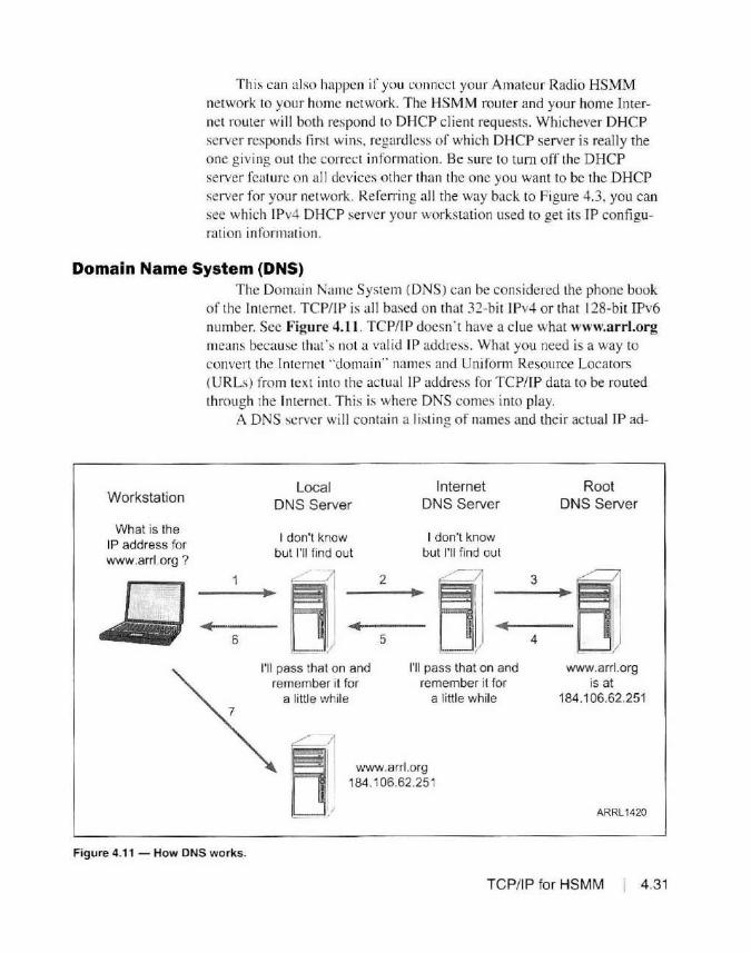
This can also happen if you connect your Amateur Radio HSMM network to your home network. The HSMM router and your home Internet router wi ll both respond to DHCP client requests. Whichever DHCP server responds first wins, regardless of which DHCP server is really the one g iving out the correct information. Be sure to tum off the DHCP server feature on all devices other than the one you want to be the DHCP server for your network. Referring all the way back to Figure 4.3, you can see which 1Pv4 DHCP server your workstation used to get its IP configurat ion information.
Domain Name System (DNS)
Workstation
What is the IP address for www.arrl.org ?
~
The Domain Name System (DNS) can be considered the phone book of the Internet. TCP/IP is all based on that 32-bit 1Pv4 or that 128-bit IPv6 number. Sec Figure 4.11. TC P/lP doesn ' t have a clue what www.arrl.org means because that's not a valid IP address. What you need is a way to convert the Internet "domain'" names and Unifom1 Resource Locators (URLs) from text into the actual IP address for TCP/IP data to be routed through the Internet. This is where DNS comes into play.
A DNS server will conta in a listing of names and their actual IP ad-
Local Internet Root DNS Server DNS Server DNS Server
I don't know I don't know but I'll find out but I'll find out
~ 2
~1 3
~ 6 5 4
I'll pass that on and I'll pass that on and www.arrl.org remember it for remember it for is at
a little while a little while 184.106.62.251
/ ~ @! J www.arrl.org LJ/ 184.106.62.251
ARRL1420
Figure 4.11 - How DNS works.
TCP/ IP fo r HSMM I 4.31

4.32 Chapter 4
dresses. When asked to provide an IP address for a URL that it does not know. it forwards the request to an upstream DNS server. The DNS request travels upstream until it either finds a DNS server that knows the con ect IP address. uses the top-level DNS servers on the Internet (also known as the root name servers), or fail s when it cannot fi nd a match.
When found. the DNS server will send a DNS reply message back downstream to the requesting DNS server. which firs t stores the information in its local cache and then sends the information on lo the c lient. The client will then proceed normally with its TCP/IP data using the IP address it received. lf a match can ' t be found, a DNS lookup failure message is returned back downstream to the requesting DNS server. who then reports the failure to the client.
All of this is done behind the scenes, but you can type the actual IP address for www.arrl.org of 184.106.62.25 l into your web browser address bar and it wi ll take you to the ARRL website. You can imagine how cumbersome thi s would be if you had to manuall y type the address for every website you wanted to visit.
The Top Level Domain Name servers contain the master li st of all of the registered Internet domain names. This name registry is mai ntained by the Internet Corporation for Assigned Names and Numbers (ICANN). In your home network, your home router often serves as the firs t DNS server in the chain. Based on the conliguration it receives from your ISP, it will usually use a DNS server operated by your ISP when it needs to forward a DNS request.
There is no requirement as to which Internet DNS server you choose to use, since in the encl. they all use the same master list. Some network technologies. such as Microsoft's Active Directory. require that the workstations in the Active Directory domain must use one of your network's Active Directory domain's DNS servers to properly register the workstat ions.
Referring all the way back to Figure 4.3, you can see that my home network is configu red to use Google ·s public DNS servers at 8.8.8 .8 and then my local router for DNS requests in the event that there is no response from the Google DNS servers. I use the Google public DNS servers because they are advertised as faster and more efficient and they also use the DNSSEC secure DNS protocol, which is resistant to DNS hijacking attempts by hackers. It 's all a mailer of personal preference as to which DNS server you use, and using the DNS server provided by your home router an<l your ISP works just fine.
The Amateur Radio HSMM networks also rely heav ily on DNS. In the BBHN and AREDN implementations, the DNS service runs on each node and is used to ··resolve" the actual IP address of a node from its node name . You can also configure your node to advertise services through
DNS which are then accessible by name in addition to the IP address. We' ll cover how to <lo this in Chapter 8, Deploy ing HSMM .
With Ham WAN, DNS servers are typically maintained by your HamWAN group at vaii ous locations on the network, usually at cel l sites and/ or server locations. Since condi tions at a eel I site are not always ideal for servers, the servers may be housed at a nice comfortable location, safe and away from the elements and are connected to the rest of the network via a client node. Client nodes on the Ham Wan network are configured to use the HamWAN DNS servers on the Ham WAN network.
Virtual Local Area Networks (VLANs) While not a part of the TCP/IP protocol suite. virtual local area net
works (VLANs) are often used to isolate physical LANs from each other, as well as providing the capabi li ty of having multiple, separate LANS traveling over a single network cable. The use of VLANs in Amateur Radio HSMM networks will most likely become more prevalent because of the single Ethernet port on the Ubiquiti and MikroTik wireless routers.
By implementing VLANs. multiple distinct and separate LANs can be created using a single network interface. YLANs operate at Layer 2 of the OSI model and only deal wi th MAC addresses and VLAN "tags:· not IP addresses. Using the 802.1 Q protocol, the Layer 2 data frames are "tagged" with a YLAN identifier that 802. 1 Q capable devices such as managed switches use to separate out the various virtual LANs. All untagged traffic is placed into the ''default YLAN." usually VLAN l.
To implement VLANs, you will need to use managed switches in your network instead of unmanaged sw itches. An unmanaged switch does not have the ability to interpret the 802.1 Q tagging information and will ignore it. passing the frame with the tagging information unchanged. as if it were just a normal data frame. A managed sw itch will process the 802. 1 Q tagging information and can separate out the virtual LAN traffi c. For example, on a managed switch. you can have individual ports ass igned to a VLAN, and only traffic on that specific YLAN is passed hy those switch ports in the VLAN.
At a central node. such as a Ham WAN cell si te. you can configure VLANs on the MikroTik router to have a default VLAN. which is usually defined as VLAN I. for general client node tra ffic. VLAN 2 would be defined for links between your ce ll sites, and VLAN 3 defined to handle traffic destined for your li nk to the Internet. This allows you to isolate an<l opti mize your traffic. One of the cool things about YLAN tagging is that the various Layer 2 links between Amateur Radi o HSMM nodes can act as VLAN "trunks,'" passing all of the various separate YLAN traffic over a single RF data link.
TCP/ IP for HSMM 4.33
Because the ent ire wide area network (WAN) is basically operating at Layer 2. you can use managed switches anywhere in the WAN and separate oul the VLANs 10 specific switch ports at any node. For example, using our hypothetical VLAN conliguration above. we can have the traffic destined for the lntcrnel traverse the WAN and. at a node connected 10 the lnlernet. we can have the Internet router connected to a sw itch port assigned to our Internet traflic VLAN - VLAN 3. The lnternel router wi ll only see the traffic on VLAN 3, and has no idea that there are any other VLANs on the network.
There is a close relationship to VLANs and IP routing. Since each VLAN is a separnte Layer 2 network, you essentially create a separate Layer 3 IP network at the same time. Dev ices on a VLAN are on !heir own separate network segment, which you can then treat as a standard physical network. An example of this is to place all of your voice-over-IP phones in a separate VLAN and JP subnet. Most VoIP phones support 802. IQ VLAN tagging. so you can simply configure the phone for lhe proper VLAN, plug ii in to lhe 802. I Q-capablc portion of your HSMM network and it will place itself' in the proper VLAN you have defined for the VoIP traffic. All VoIP phones will be on the same IP subnet and that traffi c can be isolated from all of the other network traffic.
This is a very simpli ficd overview of VLANs and 802.1 Q. Again, there are whole books written about VLANs and 802. 1 Q. As you start out, you generally won'! need 10 concern yourself with VLANs, but as you build your network out and lraftic increases, it will help to know that you can implement VLANS to help separate and manage traffic on your HSMM network.
Troubleshooting TCP / IP Issues
4.34 Chapter 4
Lastly, we need 10 know the tools available to troubleshoot IP networks and how to use those tools. As with anything else, networks don't always work as we want them to. As you build out your HSMM network. you may encounter problems such as switch loops. routing loops. rou ting en-ors, DNS issues. an<l trallic issues, among other things.
As with any troublcshooling. devising a logical method to troubleshoot a network issue is the first order of business. When troubleshooting a network issue. I usuall y slart al a known good point. a workstation thal l know works properly. Rule # I in troubleshooting: trusl nothing. Don't start out thinking you only have one problem - often you will have multiple issues that arc hidden behind lhe first issue. Troubleshooti ng a network is a Jot like solving a jigsaw puzzle. Start out by analyzing the problem logically, identifying all of the symptoms that you can. As you work through the problem. stop and re-evaluate things when the symptoms
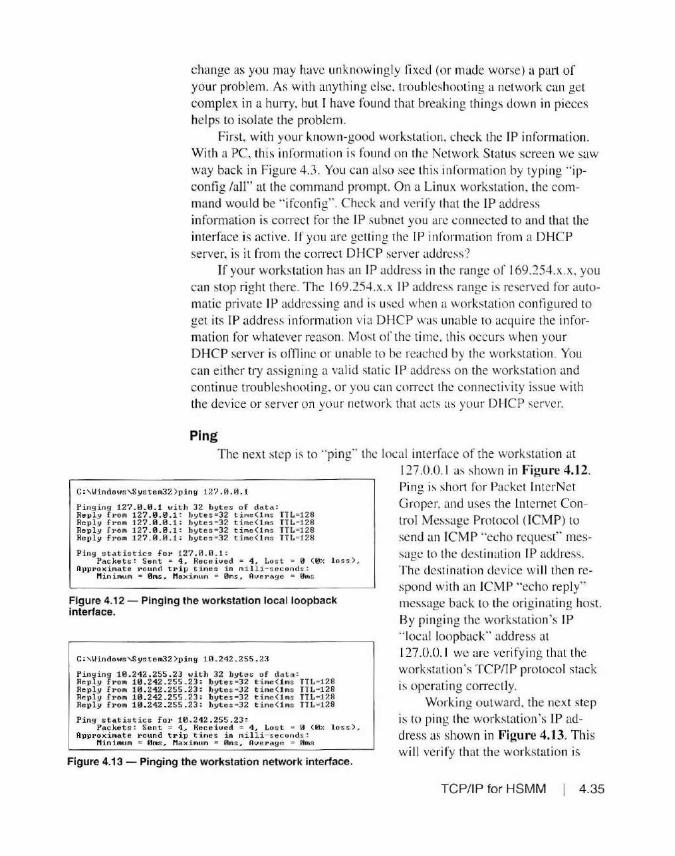
change as you may have unknowin gly fi xed (or made worse) a part of your problem. As with anything else, lroublcshooting a network can get complex in a hurry, but I have found that breaking things down in pieces helps to isolate the problem.
First, with your known-good workstat ion. check the IP information. With a PC, thi s in formation is found on the Network Status screen we saw way back in Figure 4.3 . You can also sec thi s information by typing " ipconfig /all" at the command prompt. On a Linux workstat ion, the command would be "ifconfig'·. Check and verify that the IP address info1111ation is correct for the IP subnet you arc connected to and that the interface is active. If you are getting the IP information from a DHCP server. is it from the correct DHCP server address?
If your workstat ion has an JP address in the range of 169.254.x.x. you can stop right there. The 169.254.x.x IP address range is reserved for automatic private JP addressi ng and is used when a workstation configured lo get its IP address information via DHCP was unable to acqui re the information for whatever reason. Most of the time. this occurs when your DHCP server is offli ne or unable to be reached by the workstation. You can either try assigning a val id static IP address on the workstation and continue troubleshooting. or you can com:ct the connect ivity issue with the device or server on your network that acts as your DHCP server.
Ping The next step is to "ping·· the local interface of the workstation at
Ping ing 12? .0.0.1 with 32 bytes of data: Reply froA 12?.0.0.1 : bytes • 32 time(l As TTL• 128 Reply froA 12?.0. 0.1 : byteo • 32 t i me ( lAs TTL•128 Re pl y fro " 12?.0 . 0.1 : byt eo • 32 time ( l,.s TTL=128 Re pl y f roA 12? . 0 . 0.1 : bytes • 32 t i me(l ,.s TTL• 128
Ping statis tics fo~ 127. 0 . 0. 1 : Pac kets: Sent • 4 , Recei ved = 4 , Lost • 0 (0 % loss>.
Appi•oxi Aate J:•ound t1• i p timcS: i n mill i - tocconch> : Mini"' ur"- • 0ms,. Ma x i Aum • 0Jl'ls1 Ave1•a.ge • ~ms
Figure 4.12- Pinging the workstation local loopback interface.
C: , Ui n dows,S ys tem32 ) p ing 10 .242. 255.23
~~;1tn 1,.!~ ·i=: i~~~ i~~ .2i~\~~e~~~~s t~~.~~~: : TTL• 128 Reply fro" 10 . 242 . 255.23: bytes•32 ti,..( lns TTL• 128 Re p l y fro" 10 . 242 .255.23: bytes=32 time<lAs TTL• 128 Reply fro" 1 0 . 242.2 55.23: bytes • 32 time(1 ,.s TTL• 128
Ping stat i s t ics for 10. 24 2 . 255 .2 3 : Packets: Sent = 4 , Rer.eived = 4 , Lost • 0 (0 % loss).
Approxi11t.ate i•ound t rip times in milli- cecond:;: r1in b turit -= 0ms ,. Max imum • 0mo... Ave1•ag~ • 0ms
Figure 4.13 - Pinging the workstation network interface.
127.0.0. 1 as shown in Figure 4.12 . Ping is short for Packet I nlerNet Groper. and uses the lntcrnet Control Message Protocol (ICMP) to send an ICM P "echo request" message 10 the destination IP address. The destination device will then respond wi th an ICM P .. echo reply" message back to the originating host. By pinging the workstation's IP " local loopback" address at 127.0.0. 1 we are veri fying that the workstation's TCP/IP protocol stack is operating correctly.
Working outward, the next step is to ping the workstat ion's IP address as shown in Figure 4.13. This will veri fy that the workstation is
TC P/IP for HSMM 4.35

C "\lindot1o'S yo tem32 >1ling lll. 242. 255 .1
Pinging 10.242.255.1 with 32 byte s of data: Reply f1·on 10.212.255 . 1: bytes =32 tine(1'1s TTL• G4 Revly fron 10 .212.255.1: bytes •32 ti .. e<1'1s TTL• 64 Reply fron 10.242.255 . 1: b ytes=32 t ine( l<1s TTL• G4 Revly fron 10 .242 . 25 5 .1: bytes • 32 ti<1e(lns TTL • 64
Ping statistics for 10.242. 255 .1: P<'lckct::;: Sen t • 4~ Receiued • 4 , Lost :=: 0 (0% lo ss),.
Opproxi~atc round t r ip tines in nil li- seconds: Min irnun • 0ms, Maxi mm '"' 0ms, Avei~age == 0ms
Figure 4.14 - Pinging the LAN default gateway address.
C:'-Hi ndou:;'-SystemJ2:)ping 8.R . 8.8
Pi nyi ny 8.8 . 0.8 \•dth 32 hytr. :; of data: Re~1ly ra~u '" tL8.tLO: byt c ::: :rJ2 tirrie=211ris Re1>ly from 8 . 8.8 . 8: byter. =32 t i rne=221ns Reply l't'om 8.8.8.8: bytcs=32 tirne=20ins Re11ly F1·0"' 8.8.8.8: byter.=32 tirne=19ins
PJr1g ~Lati:;tics for 8. 8.8.8:
TTL•S5 TTL•55 TTL•55 TTL•55
Pac kets: Sent • 4 . Received = 4. Lost = 0 (0% loss >. Ap1Jroxifllate round trip tillles i n 1ni lli-s econds :
Miu imuri • 19m; .. Maxi11tur1 = 22111s .. Average = 20rn:;
Figure 4.15 - Pinging the destination host address.
Pinain9 8.8 .8. ? witJ1 32 bytes of data : Request tined out. Request tined out. Requc:;t tirned Ollt. Request tirncrl ot1t.
Ping ~t~ti:::t ic ~ for 8.8.8 .?: Pnc l<ct ~: Sent • 4, Received - 0, Los t a 4 <100% lo:;:;),
Figure 4.16 - Pinging request t imeout messages.
connected to the network and is functioning properly.
Next, we' ll try pinging the defau lt gateway, as shown in Figure 4.14. Thi s wi ll verify that our LAN and default gateway are functio ning coITectly.
Assuming everything is working to this point, we can either ping the next hop, or what I usually do is go for the gold and try to ping thro ugh to the destination , in this case one of the Google public DNS servers on the Internet. Of course, in your HSMM network you may or may not have an Internet link, so you will instead try to ping another node on the network. Figure 4.15 shows a successful ping to the Google public DNS server a t 8.8.8.8. This will verify that at least TCP/IP is working at a basic level all the way to the destination and back.
Figure 4 .16 depicts what you may see if there is a failure on the path to the destination. You may see either a "request timed out" or a ''destination unreachable" message. A request timeout message means
that the ping was able to ro ute to the destination properly, but there was no response, meaning that destination host may be offline or has a firewall enabled that blocks your ping traffic. A destinatio n unreachable message means that somewhere along the way. a route to the destination could not be found. Often this is caused by an incon ect default route or default gateway setting on your workstation or a rou te r. This is why we start ping troubleshooting at the workstation and work o utward. The point where the ping fails will show the area to focus attention o n.
4.36 Chapter 4
On a properly operating ne twork. you shou ld receive 100% of the ping rep lies. If you see intermittent replies. interspersed with request timeouts and/or destinatio n unreachable messages, this indicates that the path is failing intermittently, often due to an issue with the data circuit or RF
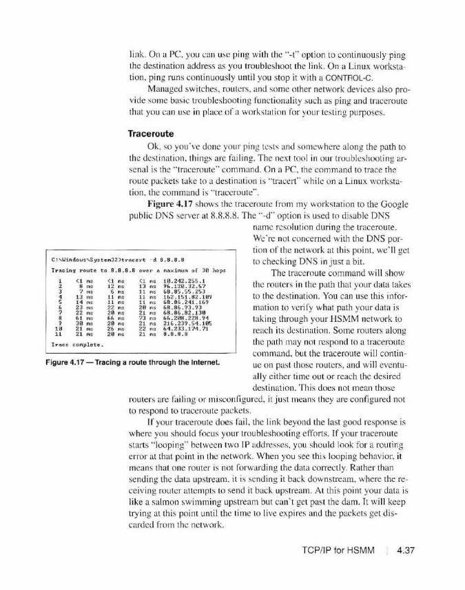
link. On a PC. you can use p ing with the ''-t" option to continuously ping the dest inatio n address as you troubleshoot the li nk. On a Linux workstation, ping runs continuously until you stop it with a CONTROL-C.
Managed switches, routers, and some other network devices also provide some basic troubleshooting functionali ty such as ping and traceroute that you can use in place of a workstat ion for your test ing purposes.
Trace route Ok, so you· ve done your ping tests and somewhere along the path to
the dest ination. things are fai ling. The next tool in our troubleshooting arsenal is the " traceroute'" command. On a PC. the command to trace the route packets take to a destinatio n is "tracer!"· while on a Linux workstation. the command is "traceroute''.
Figure 4.17 shows the traceroute from my workstation to the Google public DNS server at 8 .8.8.8. The "-d'" option is used to disable DNS
name resolution during the traceroute. We ·re not concerned with the DNS portion of the network at this point. we' ll get
c:,Uindous,Systel'l32>t .. acel"t - d 8.8.8.8 to checking DNS in just a bit. Tracing 1•oute to 8.8 . 8.8 ove1• a l'laXil'IUl'I of 30 hops The traceroute command will show
1 (1 l'IS 2 8 IQS
3 7 ... 4 13 IQS
5 14 111S 6 23 l'IS 7 22 l'IS 8 61 ... . 9 30 .. .
10 21 l'IS 11 21 l'IS
I race c omplete .
<1 ... 12 ,,.
6 ... 11 ms 1 1 ms 22 ms 21l .... 66 l'IS 20 ... 26 ntS
20 nlS
<l ... 13 l'IS 11 l'IS 11 l'IS 11 l'IS 2 0 ms 21 ... 73 ms 21 .. . 22 .. . 21 .. .
10 .242.255.l 96.120.32.5? 68.85.55.253 162 .151.82 .109 68 . 86 .241.169 68 . 86 • 93 . 93 68.86.82. 1 30 66.208. 228 .94 216.239.54.105 61.233 .174. 71 8.8.8 . B
Figure 4.17 - Tracing a route through the Internet .
the routers in the path that your data takes to the destination. You can use this information to verify what path your data is laking through your HSMM network to reach its destinati on. Some routers along the path may not respond to a traceroute wmmand, but the traceroute will continue o n past those routers, and will eventu-all y ei ther time o ut or reach the desired destination. This does not mean those
routers are fai I ing or misconligured, it just means they are configured not to respond to traceroute packets.
If your traceroute does fai l, the link beyond the last good response is where you should focus you r troubleshooting efforts. If your traceroute starts " loopi ng" between two IP addresses. you should look for a routing error at that point in the network. When you see this looping behavior, it means that one router is not forwarding the data correctly. Rather than sending the data upstream. it is sending it back downstream. where the receiv ing router attempts to send it back upstream. At th is point your data is li ke a salmon swimming upstream but can't get past the dam. It wi ll keep try ing at this point until the time to live expires and the packets get d iscarded from the ne twork.
TCP/IP for HSMM 4.37

DNS Resolution Testing Assumjng that all the pings and the traceroute worked, this tells you
that your network is function ing as it should at a basic connectivity and routing level. The next step in troubleshooting is to test DNS resolution. Remember. DNS is what is u~ed to translate between IP addresses and host
names on the network. Once we have verilicd the basic connectivity to the network, we
C: ' U inllo~·1:: 'Sy!: t cft'32 )n~ lookuv Default. S1: rvcr: yooyle-public -dn~ -a .9ooglc.com Oddrcoe: 8.8.8.8
can then check to see if DNS
) a rr) .urg St:rvcr: gnoglt:- 1)ublic-d1n; - .,, _google .corri Odd ra ••= 8.8.R.8
is functioning properly. To do this, we use the "nslookup'' com mand as shown in Figure 4.18 to look up the DNS information for arrl.org. We can use nslookup to perform an IP address to DNS name conversion, or we can use it to perform a DNS name to
Hon- Autl1f11•itntivc nn:;wcr: H.-~mn : arrl.nrg Oddrc•,: 181 . 10(,.67..251
> 184.106.62.251 Sr.rvn r : gong l t: - puh L ir.-dm;-a.google . COll'I
Address: 8.8.8.8 IP address conversion. You can also do an
Harne : www.~1· 1• 1. org Addres s: 184.106.62.251 nslookup using a node name on your HSMM
network to verify that DNS is functioning properly on your network.
Figure 4.18 - Using nslookup to verify DNS resolution.
Ir the nslookup is successful, you will see the domain name and the IP address for
that domain. If it fails. you will receive a "non-existent domain" error. Once you receive an nslookup successful message in your network troubleshooting, you can be reasonahly sure that your HSMM network is functioning correctly.
Examining the Network Traffic
4.38 Chapter 4
Someti mes you may have to j ust get down and di11y and inspect the actual data flowing on your network. To see the actual data on the network, we can use the Wireshark packet capture and analysis program available for free from www.wireshark.org. You can use Wireshark to capture data packets seen on the PC's network interface to analyze the individual data packets on the network. I o ften use Wireshark to look for viruses and other unusual traffic on a network.
You can connect your PC to a managed switch, and if the switch has the ability. you can enahle "'po11 min-oring ... Port mirroring allows you to monitor the traffic on another switch port without having to insert a hub or connect your workstation to that switch port. Thi s is also known as Switched Port Analyzer (SPAN) and Remote Switched Po11 Analyzer (RSPAN) on Cisco switches. and Roving Port Analysis on 3Com switches. Since you're working with a switched network, your workstation can only see the data that is sent on its switch port. lt can't see all the network traffic unless you plug your workstation into a hub on the network or use port mirroring. If

fit• f dit Yiew ~ "-"'ptuu1 &ily:• iUt11t1u Tt:l-tpllon;t ytitdcu Jooh
4 11! ~ "' ,r,.": ~e q .,.~ ~ ~i:.~~ e.e.e.l! oo~' "' dJr,?l.;i·~ fi.!,•·r ~--~., ~ f'kl Tme_ Stv<e
n1 44. 124 1aa ie. 242. 2ss. 7S
'" 44.126283 18.242. 255.31 7'4 44. 134'29 HJ. 2·U.255 .3S 715 44.134469 ltl.242 . 2~ 5.lOl
n& ~.134569 l tl.242 . 255.leJ 717 44 .137082 19.242.2SS. l8
778 44 .137E9-a ltl.241. 255 . l 719 &4. 265998 19.242. lSS .38
718 44 .26693¢ t&.242 .255.Je 711 44.)95'!61 18. 242.255.J& 112 <;.4. ~8'ill8S l<l .242.255.183 713 ~.3e7es.; 10.2•2.2s~.Je
714 .v.. ~07244 10. 24 2.255. l lU
786 44. 323486 Dell_70:8f :Jt: 737 44 . 327914 Dell 1e :ef:Je 7&1!1 44,jl3740 oe n :1e:0f :le
789 44. 478916 18.242. 255. 20 790 44 . 6A2'ii59 lG. 242.U5 . Se
712 •5.159269 1e.2• 2.2ss.se 7' ] 45.675528 1G. 24Z.255.S8
79S 47 .0&6965 10.2.42 .255.193
- - -----~m.,bon
19.242.255.103
19.2•2.255.10)
10.":<'42.1S5.1U
ie.242 . 2ss .3e
19.24l.255.31l
19.242 .255.l<H
Ht.24.l.. 255.lU 19 . 242. 25S.18l
10 . 242 255 . lU
18. 241 255 .lU
10.242 25"i.Je
16. 242 255.193
10.2'42 . 255 .10
Sro~d c •~t
8r<i~dCH"t
8ro11dca s"t
10.24~ .255.103
19.24 :.'.255 .103
10 . 14 2.2-S'!i.lCl
lf. 2.C. ! . 2!>5.18J
239 . 2S5. 255 .158
Pli:to<.~
TCP TCP
re• TCP HT IP
re• SSDP
leogth lnfu 60 49316 .... 56100 [.P.CKJ Seq .. l3•7 A.clc•190 Wl n• S472 t en"e 6'9 49119 .. 56999' [,l.CKJ 5eq• 1G36 A.ck•198 'lfJn• 5472 l en.z9 60 89 - 56398 (5Ytl, A<ICJ ~·0 A<i.:•t W1n• l l529 l en-e X5Szl46e S4 SG998 ... ae (.:.cq Se q• l Ad:•t Wi n•6'243 len •0
251 GE1 """on_ba.'!.iC.1(;111 hTTP/1.1 68 80 .. 56998 (ACK) Stq• l Ack• l99 wJn•lJ322 Ltnae
384 HnP/l. l 200 Ok U0P 289 49194 .. 5'5191 LM .. 247 UOP 289 .S9194 .. SS19l tiM .. 147
HTlP/X... 1191 t! TTP/ l . J 188 OK
TCP S4 56e98 .., 8 e UW, A.U'.) S~q• l99 .t..ck •1t4 5 loo' ( n .. 63896 t.en-..9
TCP 60 89 .. 561!98 [ FIN, AC(] Seq• l145 .ack• 199 Wl n• ll520 u n-..e TCP 54 56898 ... 8e [ACK) 5e q• 21110 Ad.•1146 Wln•6l0 96 l~n ·e
ARP 60 who h •~ 10.242 . 2.55 .41t ? ldl 10.242.255.10 1 60 hti<l h ils 10.21u .2ss.so? r c ll 10.2•2.255. u n
AflP c.o Who h u 10 ,242-.255.80! Te ll l0 .24:Z.:ZSS.182 UDP 361 5)5851 .. 55191 Le n•321 SSl>fl' 1.84 HTTl>/1.1 200 a<
SSOP 28£ HT"Tl>/ 1.1 290 Ok
'!I.SCP 28£ HTTP/1.1 290 OK
SSOP ll9 M•SEARCH • HtTP/ l . l
'""" '' ·;,9 bytu ~ wi'< (im_b_lt....:>)=, =.,:.::, =.,.=.,=, =<>=.,=.,=..,=(=ll=ll=b=::it=<) on lntod•« e f t twrnet II, Src: h'htronJ. dl:da :7S ( f l: itf:4l:dl:d.1:7'S ) , Ost : !Pv-4lllC.1st_'H:ff:h (el :00:5e : 7f:ff:fa) lnte-r n t:t Protocol Yers i on 4, Src: l l.142.1'ii5.UH, Ost : ll9.2~5.l.55.25e
~ user Data gra• Protocol, Src Port: 5'U9l (55191}. Ost Pert: 1900 (lHt)
lo-~J'.nigs'f'~tocG ··-----:.---~"--~""-•~-~
, .
01 oe Se 7f ff h ii. 0f- ··4l dl da 75 98 09-tS e-0-·-~-:-;;·.-,-.---==== = = ==·-···-.. -··---·----·--·--·- -
00 7d es ae oe ee et ll l>9 7c "'fl rt 6J t:f ff . } .... . .. 1 . •. g . . ff h d ' 97 07 6c e.0 69 u dd 4d 1d 53 4<; 4 1 §2 .... , Li .. M·5!.4.A 4~ 48 ] it 2.11 28 48 S4 SA self l l 2t n ed e • .:.s {H . HT1 P/ l. l .. 11 6f 73 74 3.11 32 3J 3'il 2, 12 35 35 2t l2 35 !5 le o~t: 2l9 . 255.255. J2 35 30 l" l1 39 38 ?8 ed t• 5l S<I JI 75 ;-e f.e 258 :1998 •• S T:upn 7e 11 72 6f 6f 7.- 64 ES 76 69 6) 6S 6d 0..11 4d 61 p:root:de vice .. Kl k la 22 13 73 64 78 3., 64 69 7l n 6f 76 65 72 n:·udp: disco ... er
l'-1 22 6d e1 ~ s a 111 u ed ti• ed ea • . . roe: 1 • • ••
07 P.te::J.ets: 195 · [)spla~ 795 000-0%)
Figure 4.19 -The Wireshark packet capture and analysis tool .
you·re lucky enough to have a managed switch that supp011s remote port mon itoring, you can pe rform remote ana lysis on switch po11s without hav
ing to be at the physical point in the network you wish to analyze. Figure 4.19 shows a sample Wireshark trace on my BBHN node. As
you can see, each individual data packet seen on the network interface is captured, categorized, and displayed for analysis. Each packe t captured by Wireshark is displayed w ith a tirnestamp, source and destination IP ad dress. the protocol used in the data packet, and other informatio n about the packet captured . At the bottom of the Wireshark screen you can inspect the actual raw packet data. You can a lso enable name resolution in the packet analysis. at the Layer 2 MAC level, the Layer 3 Network level and the Layer 4 Transport level, saving you the effott of having to decipher and determine w hat network device each MAC and IP address in the packet capture is associa ted wi th. It's not often that you should have to use Wireshark on your HSMM ne twork, but it's a good tool to have in your network troubleshooting toolbox.
TCP/IP for HSMM 4.39

In Conclusion
References
4.40 Chapter 4
Finally, we've reached the end of all things TCP/IP as it re la tes to our Amateur Radio HSMM networks. As you can see. there are a lot of moving pieces involved in a working TCP/IP network, and a breakdown in any one of those pieces can create quite a mess.
I know this is a lot of material to absorb, and probably a lot o f it may still sound like Greek to you. There's just no easy way to di scuss TCP/I P without going down those hundreds of little side roads and seemingly useless bits of information. However, the more you work TCP/IP, especially as you begin to implement the various applications and services on your HSMM network. the more you will begin to understand how all these pieces come together to form a fully functional. versatile, and robust HSMM network. Fortunately, a lot of the more intricate detail s are handled behind the scenes for us automatically, but it never hurts to know how it all works together to get your data where it needs to go. If you want to learn more about TCP/lP, I recommend reading the TCP/IP Guide at www. tcpipguide.com. This is an excellent source of informatio n on both !Pv4 and 1Pv6.
Now that we 've drained the swamp a bit, we're off to get started with what we' re really trying to accomplish with our Amateur Radio HSMM network, the applications and services s ide of things. This is where we wil l finally answer that burning question "Ok, so now what do I do with all th is stuff?"
www.coffer.com/mac_find/ www.ietf.org/rfc/rfc1518 www.ietf.org/rfc/rfc1519 www.ietf.org/rfc/rfc1631 www.ietf.org/rfc/rfc1878 www.ietf.org/rfc/rfc2460 www.ietf.org/rfc/rfc2474 www.ietf.org/rfc/rfc3168 www.subnetmask.info www.tcpipguide.com www.wikipedia.org www.wireshark.org

Chapter 5 ~----·- --
HSMM Applications
The number one question at virtually every Amateur Radio HSMM hamfest forum. demonstrat ion. or club presentation I have attended is. '·All this high tech networking sounds great. but what can I do wi th itr Up to this point. we have focused on the hardware and technology to create the infrastructure of an Amateur Radio HSMM network. but. using the car and highway analogy from earli er. to this point all we have done is tal k about how to build the road. For an HSMM network to be of any use, it needs applications and services to run on thi s road that we·ve built. But what applications can you run? What network services can your network offer'? How can you set all of thi s up? That's what this chapter is all about - an introduction to the various types of applications and services you can run on your HSMM network. and how you can set them up.
Because an Amateur Radio HSMM network is based on the TCP/IP protocol. you can implement many of the same applications and services found on the Internet. The on ly restriction is that your data and applications must be compliant with Par1 97 of the FCC rules for Amateur Radio. That means the data can't be encrypted, the network can't be used for business purposes. you must identify every 10 minutes. and so on.
For basic compliance with the FCC rul es. BBHN, AREDN. and HamWAN automatically handle the 10 minute ID pmt of th ings, so the two biggest things you have to keep in mind as you begin to deploy appli cations on your HSMM network is the Jata encryption and the "no bus iness use" side of things. Fortunately. we have some nice applications and tools we can use to help with this. We' ll discuss them in this chapter and the next chapter.
HSMM Applications I 5.1

So now we reach the question of, "What specifically can I do with my HSMM network?" As with the public Internet. you can set up web servers, fil e transfer servers. video and photo sharing servers. voice-over-Internet protocol (VoIP) phones, and e-mail servers. You can also use your HSMM network to li nk repeaters, place remotely-operated webcams on the network. and even set up remote control o f your station over the Internet and your HSMM network. With the ability of your HSMM network to link to the public Internet. you can implement Echolink and AllStar (Amateur Radio VoIP systems) on your repeaters through your HSMM network. Essentially. you can build o ut your own minia ture version of the In ternet that will remain onl ine in the event of a disaster, capable o f providing services even when the public Internet is unavailable.
Voice-over-IP (VoIP)
Asterisk VoIP
5.2 I Chapter 5
One of the primary applicatio ns you may want on your HSMM network is voice-over-IP (VoJP). If you've ever used Skype or Google Talk, you' ve used VoIP. Your co mputer links to the Skype or Google Talk servers that manage the VoIP connections for you, including the abi lity to link into the regular te lephone system.
Using the open source Asterisk-based VoIP application, you can set up your own VoIP "Call M anager" and implement your own full-featured VoIP system over your HSMM network. You can use standard Session Initiation Protocol (SIP) VoIP phones, or a SIP "softphone," which is a VoIP phone application that runs on your PC, similar to Skype.
As d iscussed earlie r, one of the plans I have for o ur HSMM network is to se t up a VoIP system and place a VoIP phone o r softphone at the vario us publ ic service sites in the area such as police and fire stat io ns, hospita ls. and emergency management agencies. T hat wi ll allow them a direct redundant link among the agencies in the event of the loss of thei r normal means o f communication. The cost of doing th is is negligible. since the Asterisk-based VoIP software is free. the softphone applications are free. and the cost of a used IP phone is o ften less than 550. Even if you chose to buy the IP pho nes new. you can get very nice ones for around $80 each. A ll you need to set up the VoIP server is a standard workstatio n capable of running Limn. It doesn "t need a whole lot of horsepower, and there are even Asterisk d istributions that ru n on the Raspben-y Pi .
Created in 1999 by Mark Spencer of Digium, Asterisk is an open source, fu ll - fea tured software implementation of a te lephone Private Branch Exchange (PBX) system. Orig inally desig ned for Linux, Asterisk now ru ns on a varie ty of operating systems, including Mac OS X and Win-

FXO-FXS: Trunks Explained
With VoIP, we get a whole new set of acronyms to learn. When you start setting up an Asterisk VoIP system, you'll hear terms such as FXO, FSX, ATA, SIP, IAX, and SIP trunks among others. We'll take a brief minute to explain these new acronyms, but it is important to note that as we plan to use a VoIP system in our HSMM networks, we probably won't be dealing with anything other than SIP phones and maybe FXO interfaces. But, we'll cover them all, just in case.
FXO - A Foreign Office Exchange (FXO) interface is a card or a network attached interface that allows you to connect your VoIP system to the regular telephone system. They come in many varieties, supporting single standard phone lines, multiple standard phone lines, or PRI data circuits.
FXS -A Foreign Exchange Station (FXS) interface is used to connect a standard analog telephone to your VoIP server. Some interface cards have modules that allow you to mix several FXO and FXS modules on the same card.
ATA - An Analog Telephone Adapter (ATA) is usually a network-attached module with an Ethernet interface and one or more FXS adapters. It is used to connect a standard analog phone to your VoIP system.
SIP - The Session Initiation Protocol (SIP) is the communication protocol used by VoIP devices to communicate with the VoIP server. It is the most common protocol used in VoIP phones.
IAX - Inter-Asterisk Exchange (IA.X) is the communication protocol used to link multiple Asterisk systems together, allowing for distributed Vol P systems, each serving a separate group of users but allowing direct dialing between systems.
PAI - Primary Rate Interface (PR~ is a standard telecommunications interface used for voice and data, based on the T1 /E1 data circuit and is comprised of 24 separate T1 data channels in the US and Canada, 32 E1 channels in Europe.
SIP Trunks - As telephone technology transitions away from traditional land-line based to an Internet-based technology, telephone service providers now offer SIP trunking, which allows access to traditional telephone networks using an Internet connection. SIP trunks use the SIP protocol to link a VoIP system with the telephone service provider who provides a gateway to the standard telephone network without the need for standard telephone lines.
doll's . Many companies and organizations use Asterisk. Several of the Mississippi K- 12 school districts I work with use Asterisk for their phone and intercom system for the entire school district.
Asterisk is very versatile, supporting many versions of IP phones. You can even link multiple Asterisk systems together, creating a unified VoIP phone environment. Asterisk even includes high availabi lity reatures (although you do have to pay for them), allowing you to have multiple redundant Asrerisk servers that will automatically come online in the event your primary units fail. With the addition of what is known as a Foreign eXchange Office (FXO) card or device. you can link your Asrerisk system to the regular phone system. using a standard single phone line, mu ltiple individual phone lines, or Primary Rate Interface (PRI) data circui ts. You can implement SIP trunking on your Asterisk system, and you can even link your Asterisk system to a service such as Google Talk . Sec the sidebar for more about FXO, FXS. PR!. and SIP trunks.
HSMM Applications I 5.3
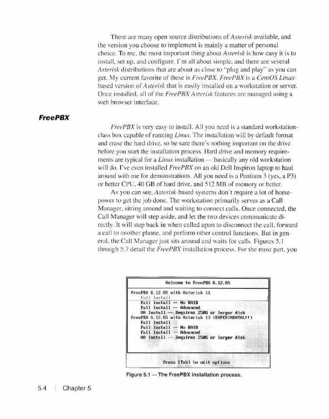
Free PBX
5.4 Chapter 5
There are many open source distri butions of Asterisk available, and the version you choose to implement is mainly a matter of personal choice. To me. the most important thing about Asterisk is how easy it is to install. set up. and configure. rm all about simple. and there are several Asterisk distributions that are about as close to ··plug and play .. as you can get. My current favorite of these is Free PBX. Free PBX is a Ce11tOS Li11uxbascd version or Asterisk that is easily installed on a workstation or server. Once installed. all of the Free PBX Asterisk features are managed using a web browser interface.
FreePBX is very easy to install. All you ncecl is a standard workstationclass box capable of running Linux. The install ation will by defau lt format and erase the hard drive, so be sure there's nothing important on the drive before you start the installation process . Hard drive ancl memory requirements are typical for a Linux installation - basically any old workstation will do. I've even installed FreePBX on an old Dell lnspiron laptop to haul around with me for demonstrations. All you need is a Pentium 3 (yes, a P3) or belt er CPU, 40 GB of hard drive. and 5 12 MB of memory or belier.
As you can see, Asterisk-based systems don't require a lot of horsepower lo get the job done. The workstation primarily serves as a Call Manager. sitting around and waiting to connect calls. Once connected. the Call Manager wi ll step aside, and let the two devices communicate directly. It will step back in when called upon to disconnect the call , forward a call to another phone, and perform other control functions. But in general. the Call Manager j ust sits around and waits for call s. Figures 5. 1 through 5.7 detail the Free PBX installati on process. For the most part. you
Me lc0'1e to FreePBX 6.12.65
FreePBX 6. 12. 65 with Aster isk 11 Fu! I Ins t a 11 I Full Instal l ~ Ho RA ID Full Inst al l ~ Aduanced HA Install ~Requires 250G or larger disk
FreePBX 6.12.65 with Asterisk 13 CEXPERl"EHTAL!! l Full Install Full lnstal 1 -- Ho RAID Full Install ~ Aduanced HA Install -- Requires 250G or larger disk
. .•·,
Press CTabl to edit opt ions
Figure 5.1 - The FreePBX installation process.

Configure TCP/IP can take the recommended default at each installation screen and you will end up with a working VoIP installation. io•m•!lll'.lllmlllM''·1
·•1'11
"'11
[ J Enable 1Pv6 support Typically. you will want the standard
full installation of FreePBX, in th is case, FreePBX 6.12.65 with Asterisk 11. the top option in Figure 5.1. The HA INSTALL option allows you to create a high availability system with multiple redundant Call Managers. I recommend start ing out with the basic full installation until you become more comfort-
(•) Automatic C ) Automati c, DHCP only C ) Manua l configuration
Figure 5.2 - Choosing the TCP/IP configuration options.
able working with FreePBX, but it's nice to know we have this option available.
The next step in the installation process is to configure the TCP/IP settings for your FreePBX server. You will want to use the 1Pv4 manual configuration options (Figure 5.2) so that you can assign a static IP address to the server. You will most likely want to di sable the 1Pv6 support, since we're not planning to run 1Pv6 on our HSMM network.
For the initial installation, you will want to use a stati c IP address and DNS server that works on your local home network so that you can download and install updates as part of the install ation rroccss . Later, after the installation is complete, we'll change these settings to work on our HSMM network. See Figure 5.3.
Next, you will select the time zone to use for your Free PBX server (Figure 5.4). You can choose to use UTC or a standard time zone . If you're choosing a time zone, your city may not be listed; just choose a city that is in your same time zone.
At this point, select and enter the root password for your FreePBX server as shown in Figure 5.5. The root user on a Linux system is the equivalent of the administrator on a Windows system. T he root user has full
>------ --11 Manua l TCP/ JP Co nf i yurnt i o11 11----------<
Enter the 1Pv1 and/ or the 1Pv6 address and prefix (address/ prefi x ) . For !Pv1 , the dotted-quad netmas k or the CIDR-style prefix are acceptable. The gateway and name server fields must be valid 1Pv1 or 1Pv6 addresses.
Figure 5.3 - Assigning a static IP address to your FreePBX server.
HSMM Applications 5.5
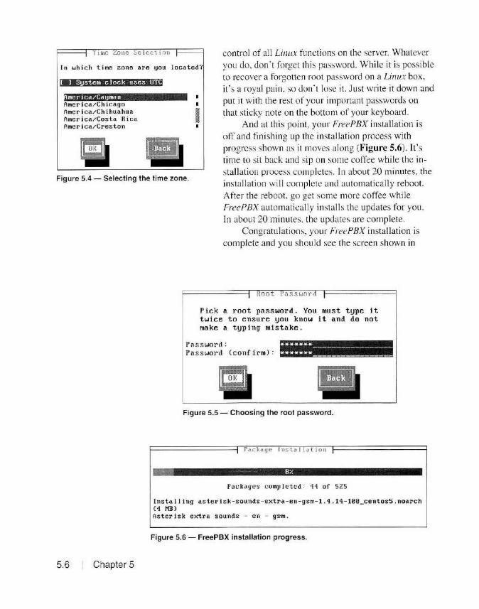
Time Zone Selection control of all Li1111x functions on the server. Whatever you do, don't forget this password. While it is possible to recover a forgotten root password on a Linux box, it's a royal pain. so don·t lose it. Just wri te it down and put it with the rest of your important passwords on that sticky note on the bottom of your keyboard.
In which time zone are you located?
[ J System clock uses UTC
merica/Cayman America / Chicago America/Chihuahua America/Cos ta Rica Ameri ca/Creston
Figure 5.4 - Selecting the time zone.
And at Lh is poin t, your Free PBX installation is off and fin ishing up the installation process with progress shown as it moves al ong (Figure 5.6). It's time to sit back and sip on some coffee while the installation process completes. In about 20 minutes, the installation \viii complete and automatically reboot. After the reboot. go get some more coffee while
5.6 Chapter 5
Free PBX automaticall y installs the updates for you. In about 20 minutes. the updates are complete.
Congratulations, your FreePBX installation is complete and you should see the screen shown in
Root Passworl
Pick a root password. You must type it twice to ensure you know it and do not make a typing mistake .
Pas s word: ****** -----~----------Password (conf irm ): ****** -----------------
Figure 5.5 - Choos ing the root password.
Package Insta l l a tion
Packages completed: 11 of 525
Insta lling as ter isk-sounds - extra-en-gsm- 1.4.14- 100_centos5 .noarch C4 MBl As ter i sk extra sounds - en - gs m.
Figure 5.6 - FreePBX installation progress.
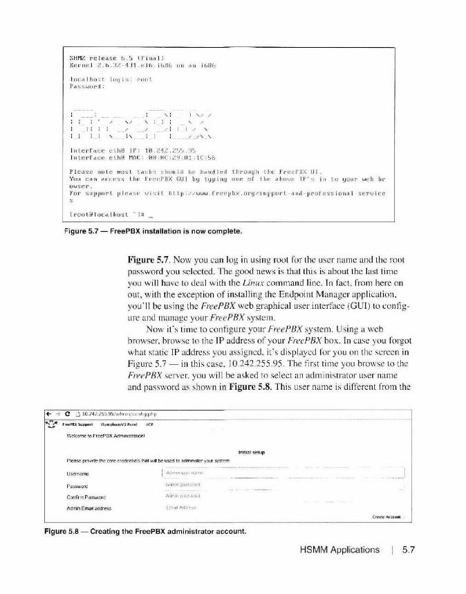
SHMZ release 6.5 (final I Kerne l Z.h . ~ Z - 1J1 . ~ lh . i GDh o n nn iGBG
l ocalhost l oyin: root Password:
: : / ' / ' : : : / /
: : : : ' ;, : - -
:
;
,; ) ' / /
) : ' / ·• -
/ ! : ) / ' / /' ' -
lnterf <1ce c lh0 JP: l.0. 212.Z'.i'.i.'J'.i Int e rf ace e lh0 Mn C : HH:HC : /~ :01 :JC:SG
Pl e,,se not e most ta »ks s hould ht: h.rnd l ed through the f reei'BX Lil . You ca n ilCr.:t;ss 1.111: Fr r:d' BX GUI by typ in11 one of tl1P. abov" IP '!; i11 to y o u r weh br owser. For S ltp1101·L 1 1 1~~ s~ vi~; il h ttµ : //www . f r cepbx . ory/s upport - a 11d - pro f ess i o 11~l service s
[rooWlocall1u s t - 111
Figure 5.7 - FreePBX installation is now complete.
Figure 5.7. Now you can log in using root for the user name and the root password you selected. The good news is that this is about the last time you will have to Jeal with the Linux command line. ln fact. from here on out, w ith the exception of installing the Endpoint Manager application, you'll be us ing the Free PBX web graphical user interface (GUI) to configure and manage your Free PBX system.
Now it's time to configure your Free PBX system. Using a web browser. browse to the IP address of your FreePBX box. In case you forgot what static TP address you assigned. it's displayed for you on the screen in Figure 5.7 - in this case. 10.242.255 .95. The first time you browse to the FreePBX server. you wi ll be asked to select an administrator user name and password as shown in Figure 5.8. This user name is d ifferent from the
+- -> C U to.242.255.9)/ admin/config.php
~ 1'-"rttPBX Supporl IS.ymphonyVl P11 n~I UCP
Welcome to FrecPBX Admimstrat100I
lniti<JI setup
Please prm1tde the core credenttals lhat will be used lo admm1ster your system
Username
Password
Confirm Password
Admin Email address
Cr~.lte'! Actoun1
Figure 5.8 - Creating the FreePBX administrator account.
HSMM Applications 5.7

+- - C _.: 10.242255.95 ·adriM (0C ' •0 :;'1p
~ r u:c PBX Sup port IS>·~ phony\'3 Panel UCP
FreePBX Administration User Controt Pane! Opera tor Panel Get S upport
Figure 5.9 -The FreePBX administrative interface.
root user and password for the Linux system portion of FreePBX. Select any user name and password you wish to use to manage your FreePBX system.
Next. select the FreePBX Administrati on Icon (Figure 5.9) and you're ready to fini sh the initial installation of your Free PBX system.
Finally. you will be asked to activate FreePBX online as shown in Figure 5.10. Thi s is an optional step. but if you plan to use any of the paid modules with FreePBX, you will have to perform the activation. As a general rule. the free version of Free PBX includes all of the modules needed for implementation of VoIP on our HSMM network. While the Endpoint Manager for the phones we'll di scuss in a bit is not included with the default installation, there is a free version that we can easily install. We won't need to purchase the Endpoint Manager built into FreePBX. You can just select SKIP to continue the activation step, and you can always activate Free PBX later if you decide you want to use one of the paid add-ons.
Welcome to your new PBX!
Thanks for installing FreePBX! Your m11ct11nt' is almcst r~Jth' toQ-::;. Btlore v~ oet ~Un('(!. wo1.. ld fOl.r hi e to .activ.a!E- ,ou • 11t'\·1 ..erver'
,\(tlv<irlar: i\ opth:mal, t><.rt ls h<ot;.:·f r~commt'r'IGt-0 . ._,,;..,.~ti11Q ~w r ~~n1~r 1-. 1~Qui1 t~ to purch.• sf: Comm@rd~! rnod~l¥1 ;inci 'P~i(I Sq;.port
I- Wouk1 you like lo ;,ctivnt<! you r new ~ystem now 1
H1i!M+.§@S
Figure 5.1 O - FreePBX activation screen.
5.8 Chapter 5

After the act ivation step, you will be shown a couple of screens of advertisements for add-ons you can purchase. You can just skip on past those - we have everything we' ll need . Eventually you ' ll get to the FreePBX Administration screen as shown in Figure 5.11.
Installing the OSS Endpoint Manager Application At this point. your Free PBX system is operational, but you need to do
some final configuration before moving the Free PBX server onto your HSMM network. For this, you will need to use the Linux command line at the server console to remove the commercial version of the phone Endpoint Manager and install a free version instead. This is an optional step, but I have found that using an Endpoint Manager to manage the phones is
+- -;':· C L.] 10.242.255.9Siadin in; conf19 php= - ·-----·--- ------------? Admin ... Ap p lications ... Connecfrvity ... Reports ... Settings ... UCP
System Overview
Welcome to FreePBX
FreePBX 12 D 76 2 'VoIP Serve~ (You can change this name m Advanced settings)
Summary Syslnfo updated D seconds ago
System Alerts Asterisk MySOL Web Server No critical issues round
Open VPN Server
Fa112Ban System Regis tration
You have a disabled module
Default ARI Admin password Used
Default Asterisk Manager Password Used
Collecting Anonymous Browser Stats
0 00 1 Mmute
Show New
Uptime
System Last Rebooted
17 minutes. 3 secon ds. ago
Load Averages
0 11 5 Minutes
Figure 5.11 - The FreePBX administration screen.
0 15 15 Minutes
Free PE Fcroe1 Comm1 Rab's Free PE C.hecH
Busine Vo!Dar Top 5 f Ma Km( Sm >ll ! Dig1um
Asteris k
Upt ime
CPU ~
Me mory
Disk •
Nerwor~
HSMM Applications 5.9
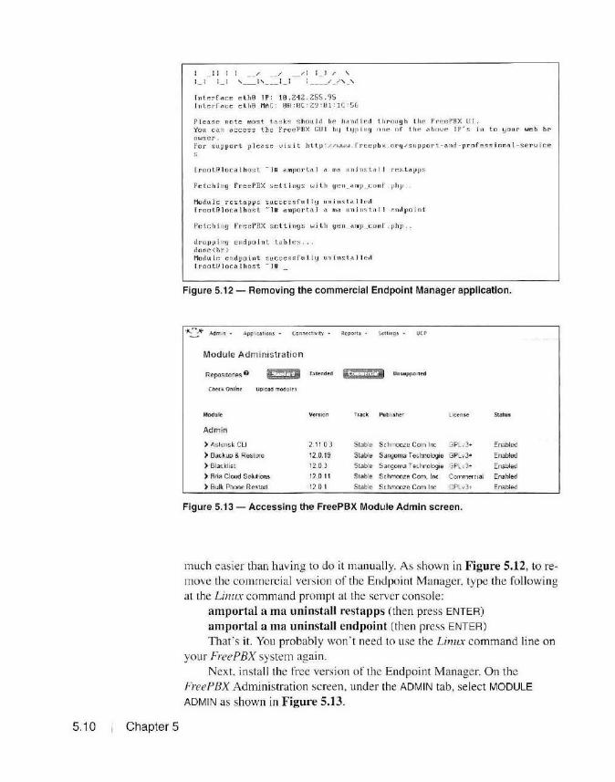
5.10 Chapter 5
/ /: : ) /
' ' ' lnt~rr.,r.e c th0 IP: 10.212 .255.95 lntcrfocc cth0 MAC: BA: 0C : Z3 : ij\:JC : 56
Please note most t4s ks s hould be l1~nrll~rl tl1rOltgh tl1~ freePBX UI. You C(\n dCCess tllc rreePDX GUI b tJ tlJp inq nne of t he ('lbnve !P 's in to lJOllr web br o wser. For sup11ort ple.'\ Se visit hltp: //WWiJ . frt:cµbx ory/support -(1.nd - professional - service
lroot@localhost - 111 t"lml10rti'J (1. m<' 11nin~t .i.ll r r.stctpJJS
Fetcl1 iny FreePBX settings witl1 yen_"mp _r.011f . pt1p ..
Modul e rcstapps succes:sfu I l y uu in s l.-:1 I led rrnot@lo1:1')ho~t -iu amportul ~' nM 11ni11s t illl ~nclpoint
rctcJ1i11g FrecPHX scttjngs witl1 ge11 ~ rn11 ._co11f .php.
dropping endpoint tables . . done<br> Mo<lu IF. endpoint sucr.essfu l l~J UH inst" I I c1I
lroot~Iocalhost -iu
Figure 5.12 - Removing the commercial Endpoint Manager application.
~ Admin ... J.pplk atiotu. • Connccti,.·ity Rt PQlt$ • Stuings • UC P
Module Administration
Reposrtofies G £DIJ E..lcttndtd 'if· I 15,.Ri Unsuppo11ed
(htd .. Onlint Uploild modult~
Module' Version Track Publiiher Licens.e St:itus
Adm in
> Aslensk CU 2 11 0 3 SI able Schmooze Com Inc GPL ,3• Enabled
> Backup & Restore 12.0. 19 Slable Sangoma Technologie GPLv3• Enabled
) Black list 12 0 3 Slable Sangoma Ter.hnologie !~Plv1 ... Enabled
) Bria Cloud Solutions 12.0. 11 Slable Schmooze Com. Inc . Commercial Enabled
> Bulk Phone Res1art 12.0 1 Slable Schmooze Com Inc GPLv}T Enabled
Figure 5.13 - Accessing the FreePBX Module Admin screen.
much easier than having to do it manually. As shown in Figure 5.12, to re· move the commercial version of the Endpoint Manager, type the following at the Linux command prompt at the server console:
amportal a ma uninstall restapps (then press ENTE R)
amportal a ma uninstall endpoint (then press ENTER)
That' s it. You probably won' t need to use the Limn command line on your FreePBX system again.
Next. install the free version of the Endpoint Manager. On the FreePBX Administration screen. under the ADMIN tab, select MODULE
ADMIN as shown in Figure 5.13.
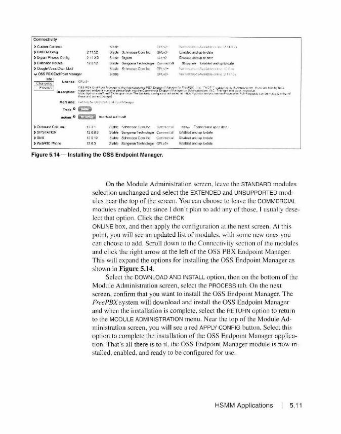
Connectivity
) Cusiom Conlexts
) DAHDi Config
) 0191um Phones Config
) E><tensioo Routes
) Google Voice.fChan r..tot1t
v OSS PBX End P04tlt Manager
2 11.52
'J 11 3 a 12 0 12
Stable
Stable SchmOoZe Com In:
Stable Oigt0m
Stable Sangoma T echnologie
Stable Schmooze Ccm Inc
Stable
GPLv2 - Nut l r~-; tdied • "~v.J:l.;~I<:" or1hm: 1 11 ·J, 1
GPlv3+ Enabled and up 10 date
GPLv2 Enabled and up to <1ate
Ccrnmcrcial rDUpgrAdt: Enabled and up to date
GPLv3+ NOf rfl">\,tl,._.,I, /1•,.J1:-1l•ie ~">'•fl~ 1. f .,,
GPLv2• Not Install(.'(! (A'ldliJbk onllnc :, 11 101
~-1"~'0-.I Ucen n : GPL·.?· Changelog I
Pre-rous I ~u~I~ ;~~n:,,~:~Z~~I~ .~~~~~~e~:i~~~~~~.Y!~~~~~l~m~~·~~01~;~ \u::0;~ ~ S~~~~~~!'~/" , oo are loOl1fl9 lor ~ Oescn pt io n : l'tttps lrg1lll\.lt:I .:om.IF1eePSX.!rodrontm.ari The bac ~ll!nd H >nh91Jra!or 1s nos1eo al N tp:s llgithull rnrntpro.,.1s iorwrrP1o·m;.Jont.lf P ull Reques t!. c an be m ac€ 11,1 e11~ of
ll'M!-Sc and <trc cnc.outaged
More Into: G .. 1 1~11! ' •)I OSS P f.)( Er d P 'J1''' Mar1Jy<?f
Tr.ick:O ~
Act!o n : 0 l:C!:I Oownlo-&d &nd ln~t•ll
) OutbolJ"id Call L1mi1 12 0 1 SI able Schrnooze Corn Inc Con1rrea.at CDSu y Enabled and up to dare
) SIPSTATION 12 0 8 .8 Stable Sangomit Technologie Cccnmercial Enabled and up to date
)SMS 12 0 19 Slable Schmooze Com Inc Commerc1.1 I Enabled and lip to elate
) WebRTC Phone 12.0.3 Slable Sangoma T echnologie GPL v3+- Enabled and up to date
Figure 5.14- Installing the OSS Endpoint Manager.
On the Module Administration screen, leave the STANDARD modules selection unchanged and select the EXTENDED and UNSUPPORTED modules near the top of the screen. You can choose to leave the COMMERCIAL
modules enabled. but since I don ' t plan to add any or those, I usua lly deselect that option. Click the CHECK
ONLINE box. and then apply the configuration at the next screen. At this point, you will see an updated list of modules. with some new ones you can choose to add. Scroll down to the Connectivity section of the modules and cl ick the right anow at the left of the OSS PBX Endpoint Manager. This will expand the options for install ing the OSS Endpoint Manager as shown in Figure 5.14.
Select the DOWNLOAD AND INSTALL option, then on the bottom of the Module Administration screen, select the PROCESS tab. O n the next screen, confirm that you want to install the OSS Endpoi nt Manager. T he Free PBX system will download and install the OSS Endpoint Manager and when the installation is complete, select the RETURN option to retu rn to the MODULE ADMINISTRATION menu . Near the Lop of the Module Admini stration screen, you will see a reel APPLY CONFIG button . Select th is opti on to complete the installation of the OSS Endpoint Manager application. That's a ll there is to it, the OSS Endpoint Manager module is now installed. enabled, and ready to be configured for use.
HSMM Applications 5.11
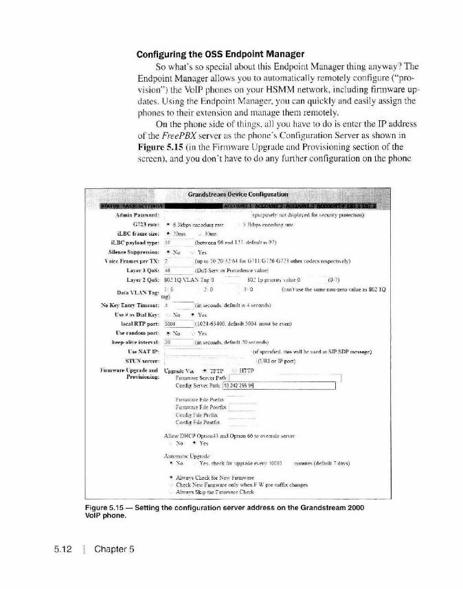
5. 12
Configuring the OSS Endpoint Manager So what' s so special about this Endpoint Manager thing anyway? The
Endpoint Manager allows you to automaticall y remotely configure ("provision") the VoIP phones on your HSMM network, including firmware updates. Using the Endpoint Manager, you can quickly and easily assign the phones to their extension and manage them remotely.
On the phone side of thi ngs, a ll you have to do is enter the IP address of the FreeP BX server as the phone's Contiguration Server as shown in Figure 5.15 (in the Firmware Upgrade and Provis ioning section of the screen), and you don ' t have to do any further configuration on the phone
Grandstream Oel(lce Configuration ..
Admio Pa~!lword :
G 723 r ;itt-: • 6 3kbp'i e-ncodmg rnte
I (purpoc;ely no t d1splay~d fo1 secun ty protection)
S _\kbp'> encochng. r;i te
iLBC fr:u11e si.u: ~· .20ms
iLBC p aylood typo: 97
., 30ms
(between 96 and 127. default 1s 97}
Sllence S uppru .. ,-;ioo : ~ ' \'o Yee;
\ "o ict' Fr ame . .., pE'r TX: (up to 10 .20 32 6 -t for G 71 l G726-G723 otl1e1 codecs respectt\ ·cly) -----
La~·er 3 QoS : 43 (Diff-Sen· rn P1ecedena rn lue)
Laye..Z QoS : 802 IQ\'l.A:" Tag O SO~ Ip priority rnluc O (0· i)
Data \ "L.-.\".\ T~g : ra~) (j ] O 3· 0 (can't U'ie the '\ame non-ZC'fO Ya1ue as 802 lQ
:"lio Key Eu r~· Timeont :
lT 'Sf" # as Dla l Key :
( in ~onds_ defouh 1s ~ seconds)
! Yes
{1 02-J-6) 4 00. default )004 _ tnU!.t b~ e\°C'.'11)
Use nodom po1t: !.· ~o Ye'-i
keep-:a li,·e in t~rio:1l : '20----, (in second~. d efauh 20 '>eComl•>)
l's. :\A T lP:
STl~="I ~ en·n :
Firmware t:'pgrade a od Provi~iooing:
-----·-- -- --(1f specified. llti~ will be used u1 SIP-SDP message)
l(URI or lP·port)
l'pg:rade Via '!' TFTP , ' HTTP F1rn1ware Se rYcr P"t-'-h i ___ ___ _ .-J Conftg Serwr Poth I 10 242 255 9~ 1 ·
F mn ware F 1le Pre fix
F mnware F i i i: Po.c_. tfr"< C'oufig F 1lc Prefo1. Config F 1le Postfi .. x
A llow DHCP Op110114 3 and Option 66 to OYemdc ~cn:er
-:'\o ~ Ye ..
Automatic Upgrade-• ~o Yes,. check for upg_iade e\·ery 10080 mumte!. (default 7 days)
• Always Check for Nc:w Fm11\\'are -' Check :\ew F mnware only when F \V pie c;uffi..x change'i
Al\\·ays Skip 1he Ftnm,·ru e Che-:k
Figure 5.15 - Setting the configuration server address on the Grandstream 2000 VoIP phone.
Chapter 5
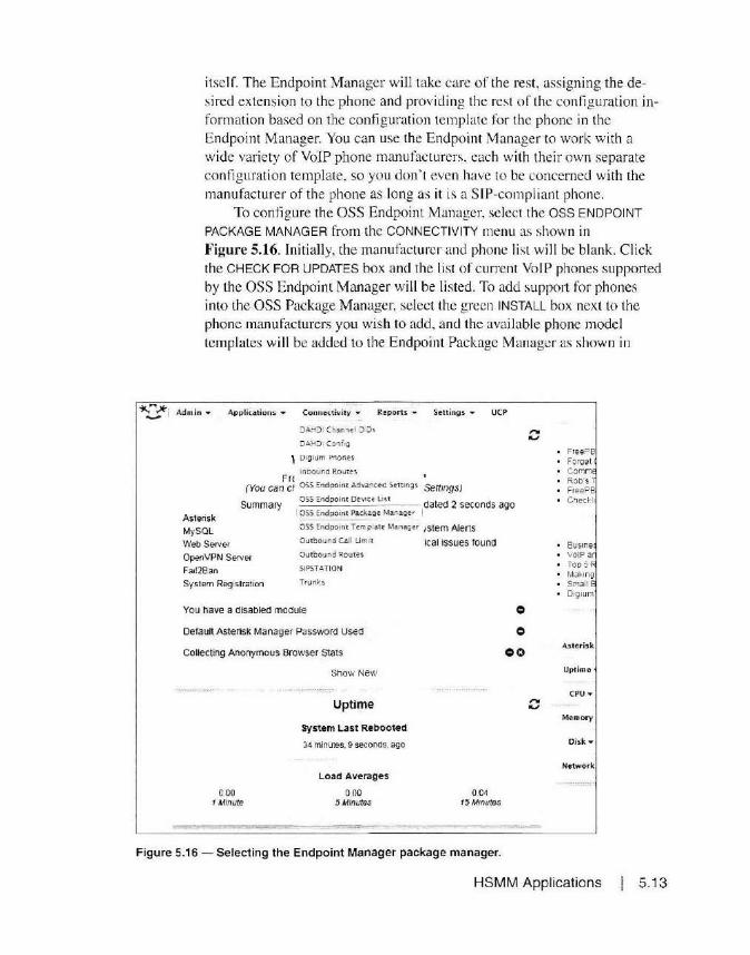
itself. The Endpoint Manager will take care of the rest, ass igning the desired extension to the phone and providing the rest of the configuration information based on the configuration template for the phone in the Endpoint Manager. You can use the Endpoint Manager to work with a wide variety of VoIP phone manufacturers. each with thei r own separate configuration template, so you don't even have to be concerned with the manufacturer of the phone as long as it is a S IP-compliant phone.
To configure the OSS Endpoint Manager, select the OSS ENDPOINT
PACKAGE MANAGER from the CONNECTIVITY menu as shown in Figure 5.16. Initially, the manufacturer and phone list wil l be blank. Click the CHECK FOR UPDATES box and the list of current VoIP phones supported by the OSS Endpoint Manager will he listed . To add support for phones into the OSS Package Manager, select the green INSTALL box next to the phone manufacturers you wish to add, and the avail able phone model templates will be added to the Endpoint Package Manager as shown in
~ Admin • Application$ • Connectivity ..... Reports ... Settings .. UCP
:JAHDI Channel 0:0~
9AHDi CoJfg
\ Dig ium P-:;ones
inbound Routes Fr!
(You can ct oss Endpoint Advane<d S<ttong, Settings)
Astensk
My SOL
Summary oss Endpo1m Device L<St dated 2 seconds ago I OSS Endpoint Packag~ Mwiager t
o ss Endpoim Temp!ate- MMager 1stem Alerts
Web Ser<er
OpenVPN Server
Sys1em Registration
Outbound Call Um 1t
Outbound Routes
SIPSTATION
Trunks
You nave a disabled module
Default Asterisk Manager Password Used
ical issues rounel
0
0
Collecting Anonymous Browser Stats 00
0.00 1 Minute
Show New
Uptime
System Last Rebooted
34 minutes. 9 seconds, ago
Load Averages
0.00 5 Minutes
0 04 15Mmutes
Figure 5.16 - Selecting the Endpoint Manager package manager.
...... "-'
f ree PS Forge t Comm Rob·s Free PB
Top 5 Ma~.ing
Small 0 1gium
Asteri~k
Uptime
CPU ..-
Memory
Oisk•
Network
HSMM Applications 5. 13

5.14
llillli!!iJGrandstream
+ Install rirmwan= Budge Tone series 1200,201]
+ _Enable BT200
+ Enable BT201
+ Install Firmwore GXP Enterprise HD series [2100,2110,2120)
+ E.m1.b1e. GXP2100
+ Enable I GXP2110
+ Enable GXP 2120
+ Enable GXP1 100
+ Enable GXP1105
+ Enable. GXP1400
+ Enable GXP1405
+ Eni ble GXP1450
+ Enable GXP2124
+ lnstallFinnware GXP Enterprise IP series [280.1200,2000,2010,2020)
+ Enable GXP280
+ Enable GXP 1200
+ En.bl• GXP2000
+ Enable GXP2010
+ Enable GXP2020
+ Enable GXP285
+ ln<tollFirmwar< HandyTone [HT486 REV.2, HT286 REV.3]
+ Enoble HT 486
+ Enabl• HT286
Figure 5.17-Adding GrandstreamVolP phone supporttothe OSS Endpoint Manager.
Chapter 5
Figure 5.17. Now, all you have to do is enable the specific phones you wish to manage using the Endpoint manager by selecting the ENABLE box.
There is one more step before we're ready to use the Endpoint Manager to automaticall y provision the YolP phones. Be sure to add all of the phone manufacturers you plan to support on your HSMM network while your server still has access to the Internet to down load the necessary template files. because the next step is to move your FreePBX server to its final IP address on your HSMM network.

.'. .. mrcskCU
t..stensk. Modules
A..ster:sk PhonEbook
eackup & Resi:ore
Blacklist
Bria Cloud Solu\ fon!.
C!D Supetftcta
Caller!D Lookup Sourtes
CenrfJCate Management
Class oi Se r111c-e
Coman M3.nag e1
Custom Destinations
Custom Extens1ofl.s
D19 ~um Adoor;s
Feaw re Codes
Free?BX Support
J,!va SSH
Module Admin
Orilme ~upport
Fnorie Restart
Presence State
REST API
Sangoma MCU
Syn ' m Aa mm
S·(Slem Rec-crdi n.;s
User Mana9ement
1S.,.mphcn)"J3
System Overview
Welcome to FreePBX FreePBX 12.0.76.2 VoIP Server
Senings •
u can change this name in Advanced Settings)
UCP
iary Syslnfo updated 0 se<:onds ago
System Alerts
No critcal issues found
j module
iager Password Used
ius &owser Stats
Show New
Uptime
System Last Rebooted
37 rr.11utes, 34 -seconds, ago
Load Averages
0 .. 02 0 04 15Minures
0
0
00
Figure 5.18 - Accessing the system admin menu.
Free PB FOf gc-1 C~nn't·
R:.b!l T F1eePB Che~k~
Bu~.e~
\'o(Pnn fop s f-.-ta ~ii.;
Sn"lll~ 6 D1Q11..in'
A.s terid.
CPU -
M~mory
Disk -
Nerwork
~-.*, Admin • -~ :;;_-
Applications ... Connectivity • Reports • S<ttings • UCP ~-~~ -
System Admin
DNS
DN S Server list 0
Submit
127 00.1 8.8.8.B
Figure 5.19- Setting the FreePBX DNS server settings for your HSMM network.
At th is point, you are ready to move the FreePBX server to its actual IP address on your HSMM network. It 's easiest to change the IP settings whi le you can still access the server at its temporary address on your network. Select the SYSTEM ADMIN functions from the ADMIN tab on the main menu as shown in Figure 5.18.
Next, select the DNS
tab and enter the proper DNS settings for your HSMM network as shown in Figure 5.19. For a BBHN or AREDN network , this will be the local IP address of your node, which is also the derau lt gateway IP address on your HSMM node LAN. For a Ham WAN network, this will be the IP address of the Ham WAN network 's DNS servers.
Finally, select the NETWORK SETTINGS tab and change the IP address, S ubnet Mask, and Default Gateway to that of your HSMM network as shown in Figure 5.20. The IP address should be a valid stat ic IP address on the
LAN side of your HSMM node. This will be the address used by the HSMM network users to access the Free PBX server. To complete the configuration , select the SAVE SETTINGS button. At this point you will no longer be able to access the FreePBX web interface until you have moved the
HSMM Applications 5.15
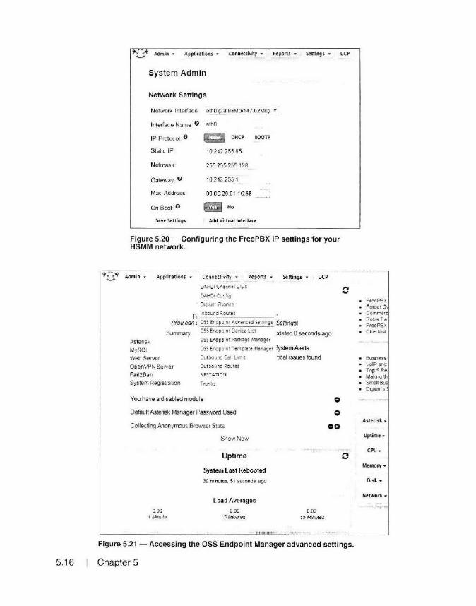
5.1 6
V Admin .. Applic-ationi .... Connectivity ... Reports .... Sen ings .... UCP
System Admin
Network Settings
Network Interface. ell1 0J_2B.BS~tbl14?.02Mb) •
Interface Name: 0 ethO
IP Protocol. 0
Static IP
Net mask
Gateway: 0
Mac Address
On Boot: O
Save Settings
~ DHC.P
10.242.255 95
255.255.255 128
10 242 255 1
00 OC29 0 1:1C:56
~ No
SOOTP
Add Virtu~l l nterfac~
Figure 5.20 - Configuring the FreePBX IP settings for your HSMM network.
~ Adm in • Appliutions ... Conne<tivity • Reports ... Settings ... UCP
DAHC1 Cha.no.et D!O:;
DAH01 Config
D1g1um Phone s
Ft .1~.~:und R_.o_u_t_es _____ _
(You can cl OS.S E.J1dpo1m Advar.ced S.ernngs _JSettings)
Summary OSI Endpomt D<vi" list xlated 0 seconds ago
Asleri s~. OSS Endpoint Package Maniger
My SOL 055 Endpomt Tempiate Ma.n.ag~r )ystem Aferts
Web Server
OpenVPN Server
Fa112Ban
Outoound Cal\ LJ m1t tical issues found
01.ftbound Routes
SIPSTATION
System Registration Trunks
You have a disabled module
Default Asterisk Manager Password Used
Collecting Anonymous Browser Stats
0.00 1 ~Atrwte
Show New
Uptime
System Last Rebooted
3!t minutes. 5 1 seconds, ago
Load Averages
0.00 5Minules
0.02 1.5 Minutes
0
0
00
,.. .....
,.. .....
Figure 5.21 - Accessing the OSS Endpoint Manager advanced settings.
Chapter 5
• FreePBX • Forget C
Comme-1c Rob's Tw
• FreePBX Checkltst
Business 'JolP ana
• Top SRe • Makilg th
SmaO Bu Digrum's
Aslerisk ...
Uptimt •
CPU·
Memory•
Nelwork ....

server to your HSMM network. At the Limn console. type shutdown -h now (then press ENTER)
to shut down the server. When the shutdown is complete. you can connect the FreePBX server to your HSMM network and power it back OIL
Once the server has booted, you' re now ready to complete the configuration on the OSS Endpoint M anager. From the CONNECTIVITY tab on the main screen, select OSS ENDPOINT ADVANCED SETTINGS as shown in Figure 5.21.
This is where you configure the g lobal settings used by the OSS Endpoint Manager. Along with the templates for each phone manufacturer, these global settings wi ll be applied to all phone templates when they are used to provision your VoIP phones. Using Figure 5.22 as a guide. enter the IP address of the phone server. select FILE (TFTP/FTP) as the confi guration type. select the desired time zone or UTC time. and enter the IP address of a Network Time Protocol (NTP) server if you would like to have your phone server time synchronized with your network time server. If
End Point Configuration Manager
Advanced Settings
OUI Manager
Configura1ion Type
Time SeNer {NTP SeJVer)
Local Paths
NMAP executable path·
ARP executable path:
Aslensk executabie path
Package Ser-~et
Enable FreePBX ARI Module C.\'ha.1?)
En.able Debug Mode 0
Disable Tool !rps 0
Allow Duplicate Exlensioos Q
Allow Sa·m;g Over Default Configu1a11on File!> 0
Disable TFTP Server Check 0
Disable Coofi9,Jrat100 File Bae kups. 0
P1oduc1 Configuration Edilor
iO 2.:. 2 255 95
F·le (ifiPIFTP) ,, .
!tf'..pt: ootr
AmeflC.i!<P:'.~.~~.9~-- __ _
~25595
tsbmJarp
!Usrtsb1r1/as1eris~
u
Use GITHUB Live Rep..'.> (~equires git to be installed) 0 U
lmportJLxport My Device~ Lisi
Figure 5.22 - Configuring the OSS Endpoint Manager global settings.
HSMM Applications 5.17

you don't have an NTP server, you can use the built-in NTP server on your Free PBX serve r. Select UPDATE GLOBALS at the bottom of the screen and your OSS Endpoint Manager is now ready to provision the phones. We' ll come back and show you how to use the Endpoint Manager to configure your VoIP phones right after we discuss the phones themselves.
Voice-over-IP (VoIP) Phones Of course a VoIP system is pretty much useless without phones. As
you saw when we were configuring the OSS Endpoint Manager, there's a whole bunch of VoIP phone manufacturers to choose from. As long as the phone is SIP-compliant, it will work with your Free PBX system. My personal favorite is the line of phones and analog-to-VoIP phone inte1faces from Granclstream Networks. I have worked extensively with the Grandstream 2000 and 2100 se1ies of VoIP phones on Free PBX systems . The Grandstrearn 2000 and 2120 series phones are full-featured four line phones with large backlit LCD displays. One nice feature is the ability to dial a Grandstream phone by its IP address, without the need for a Call Manager. While this can be handy, I prefer the added functionality and features provided by the FreePBX system. These phones are easy to configure for use with FreePBX and are supported by the OSS Endpoint Man-
ager. You can get them new for around $80 each and you can also find them used on eBay for around $40 each. Figure 5.23 shows a Grandstream 2000 VoIP phone configured and running on my HSMM Free PBX server.
Before you use the OSS Endpoint Manager to provision your IP phones, you will want to add the phone extensions for your users. You can use any sequence of numbers for your extensions, but you wi ll want them all to be the same length to simplify the dial pattern used by the
Figure 5.23 -The Grandstream 2000 voice-over-IP phone.
Free PBX system to dial the various extensions. I like to use a four-digit number for my extensions, starting at
5.18 Chapter 5

Admin .. Applicarions .. Connectivity - Reports .. Settings • UCP
~riounc.,,- ents ystem Overview AD001r1 t:-.ent Remina~ r
Sroadc..ast
Bulk DI Os
Bulk Exu~ns ions
Call Flow Control
Astens~ Call R<ccrd1ng
MySOL Calloack
Web Se1 CallerlO M3nagement
OpenVP Conf<rences
Fa112Bar Conferene<s Pro
System I DISA
Dutctorv
You ha'I Exten11ons
Default, Follow l.'e IVR
come to FreePBX 3X 12.0.76.2 VoIP Server' 7e th;s name rn Advanced Settings)
Syslnfo updated 1 seconds ago
System Alerts No critical iSStres found
NOid Used
0
0
Collecbr l anguao.s . Stats 00 MISC App !tC clLOOS
Misc Ou tin.anons
Pa91ng and Intercom
Park ano Announc.e
Par~1n9
Queue Pnonties
Queues
Ring Groups
S<t C..l!erlO
1 Tt >I To Sp .. ch
Time Cond1tiom
Time Groups
Voicemail Blastrng
l'I•~• Up Calls
Show New
Uptime
stem Last Rebooted
·. 3 minutes, ~9 se.conds. aJo
Load Averages
096 5 MtnUtes
Figure 5.24 - Adding extensions in FreePBX.
0 35 1.5M1mlfe.s
...... ...,
F1<"PI Forget
• Comm< Robs Free Pl
• Cf'l eo:~ b
. 6uS11e-/DIP er . Top Sf Making Srrlln B . 0~11..om
Ast"isk
Uptimt
CPU·
Memory
Disk.
NetworL
I 000. This gives me nine separate extensio ns ranges with 999 phones per range. I can then group the agencies together in their own four digi t address range such as 2xxx for fire and police. 3xxx for hospita ls, 4xxx for emergency management. and so on. This also simplifies the setup of your various Intercom groups, which you can use to broadcast messages to all members or the group. How you set up your extensions is a matter o f personal preference, but I do suggest that you plan out your extensions in advance to make things easier as additional users join your Free PBX system.
Adding extensions in FreePBX is very easy. Referring to Figure 5.24, select the EXTENSIONS option from the APPLICATIONS tab on the main menu.
From here, you can select the type of device to assign an extension. Go ahead and use the defaul t GENERIC CHAN SIP DEVICE and click the
HSMM Applications 5. 19

SUBMIT button. Next you will see the screen shown in Figure 5.25. Here you can assign the Extension Number and Name to Display on the phone's LCD Display. There are also a bunch of other options. but for the most part you can leave these at the default setting.
You will also want to assign a Secret entry. This is the password the phone uses to log in or "register" with the FreePBX system. You can take
Add SIP Extension
· Add Ex1ens1on
User Extension 0
Display Name O
CID Num Ahas 0
SIPAhas O
. Extension Options
Queue State Delee lion 0
Outbound CID 0
Aslensk Dial Op11ons 0
Ring Time O
Call FooNard Ring Time 0
Outbound Concurrency Limit 0
Call Wa111ng O
Internal Auto Answer 0
Call Screening O
Pinless Dialing 0
Emergency CID 0
· Assigned DID/C ID
DID Descnpt1on O
Add Inbound DID 0
Add Inbound CID 0
- Device Options
1001
KW5GP
1001
1 use StatL7]
Ttr
loetaiiit'1
I Default · ·I
I Ena~ • ]
I 0tsabie •] Disable
Dtsabte • I
This deYice uses CHAN_SIP technology listening on 0.0.0:0:5060
Figure 5.25 - Configuring an extension in FreePBX.
5.20 Chapter 5
U Ovemde
- - ------=---=-----

the recommended defau lt. but I prefer to use a simpler password that I can remember, such as some variation of .. Ext 100 l" to make it easy to remember if I ever have to manually contigure a phone, such as a VoIP ··softphone." to use the system.
Optionally. you can configure the Recording and Voice Mail options. Oh yeah, did l menti on that the FreePBX system also incl udes the abili ty to record calls and have voice mail for each user? When you have lini shed setting up the extension. click the SUBMIT button at the bottom of the screen and then the red APPLY CONFIG button ar the top or the screen. Usually, whenever you make any configuration changes to FreePBX, you will need to click the red APPLY CONFIG button before any changes take place.
While you can configure a ll of the settings on your VoIP pho ne manually, in the case of the Grandstream 2000/2100 there are three to four separate screens to configure, and even more if you choose to have the phone support multiple li nes. Herc is where the OSS Endpo int Manager comes to save the day.
Imagine if you will. tha t you have buil t out your HSMM network and have phones scattered all over the area. A new ham wants to connect an IP phone to your Free PBX system but has no idea how to set up a VoIP phone. All you have to do is walk him or her through the process of setting
End Point Configuration Manager
Device List
Add Device
MAC Addrns Brand Modet of Phone line- £1.tensloo Number
1001 - (',\5C..P •
Unmanaged Extensions
Current Managed Extension$
MAC Address
SelK* Phone(a> Optton>
ii Or1t1t Oelelt> Sele< led P l"oclncs
Brand
GXP2000 •
Add \tk\Hd P~uo
Rebool Phonet
Mod 11I or Phone Lino
O teluild Rebuild Coof1gs IOI' Selec ted Phones (1. Ret>oot ?hone~)
Jr:UlllClait Change Se4ec19d Phon&S to &a-1\d--• Mo~1 •J ( Rebool PtQNilsl
Global Phone 0Jltio n5
Q.~uo Saarth fOt' new dell'ice$ 111 n&tma~k 10242155.9 5124
o 1tdl!Hkt Rebllld C«tfl()S fa' All Phooes ~- Recoot Phones}
O ltMoc Rebool f t.s BraOO --
~Co.f\11111t ReconligUN all (prodUCIS) _ • .i wrlh • ( 'Rqooo1 Pt1one11)
xCOflf1911~ Re<. onl1guro ~t {models) __ • . wtth • ( Raooo1Phot1es)
•:Q• )("f,')GP •
E1.1enslon Number
Figure 5.26 - Linking a phone to its extension using the Endpoint Manager.
Template
lemplat" ( dll Oeh~I"
HSMM Applications 5.21
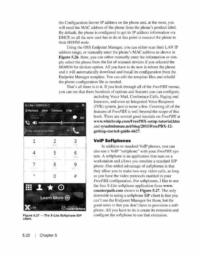
1 2 . .
4 5
7 8
* 0
the Configuration Server IP address on the phone and, at the most, you will need the MAC address of the phone from the phone's product label. By default, the phone is configured to get its IP address information via DHCP, so all the new user has to do at this point is connect the phone to their HSMM node.
Using the OSS Endpoint Manager, you can either scan their LAN IP address range, or manually enter the phone's MAC address as shown in Figure 5.26. Here, you can either manually enter the information or simply select the phone from the list of scanned devices if you selected the SEARCH for devices option. All you have to do now is reboot the phone and it will automatically download and in stall its configuration from the Endpoint Manager template. You can edi t the template files and rebuild the phone configuration file as needed.
That's all there is to it. If you look through all of the FreePBX menus, you can see that there hundreds of options and features you can configure,
3
6 •:i._J•_
9
#
including Voice Mail, Conference Calls, Paging and Intercom, and even an Integrated Voice Response (IVR) system, just to name a few. Covering all of the features of Free PBX is well beyond the scope of this book. There are several good tutorials on Free PBX at www.whichvoip.com/FreePBX-setup-tutorial.htm and sysadminman.net/blog/2015/FreePBX-12-getting-started -guide-6627.
VoIP Softphones
Figure 5.27 - The X-Lite Softphone SIP client.
In addition to standard VoIP phones, you can also use a VoIP "softphone" with your FreePBX system. A softphone is an application that runs on a workstation and allows you emulate a standard SIP phone. One added advantage of softphones is that they allow you to make two-way video calls, as long as you have the video protocols enabled in your FreePBX configuration. For softphones, I like to use the free X-Ute softphone application from www. counterpath.com shown in Figure 5.27. The only downside to using a softphone SIP client is that you can' t use the Endpoint Manager for them, but the good news is thac you don' t have to provision a softphone. All you have to do is create its extension and configure the softphone to use that extension.
5.22 I Chapter 5

Codecs
SIP and NAT
Now that we have a working VolP system, let's fall back a bit and look at how this works. The VoIP phone uses what is known as a codec to convert the phone audio into a digi tal stream and back to audio on the other end. An important dist inction to make is that codecs do not qualify as encrypti on because they use we ll-known standard protocols to digitize the audio and video data. Anyone using the specified codec can decode the d igi tal phone data. So. we don ' t have to worry about the Part 97 rules against encryption when using codecs and VoIP phones.
As discussed earlier, the SIP protocol used in VoIP does not play nice wi th NAT. This is why it is recommended to not use NAT on your HSMM network if you plan to implement VoIP. The reason for this is the SIP calling process. As shown in Figure 5.28, a SIP phone call wi ll o rig inate in a phone, which then contacts the Call Manager with a SIP Invite. The Call Manager will then issue a SIP Invite to the destination phone extension if it is online. The Call Manager then allows the two phones to communicate d irectly and d rops out o f the path, waiting for a d isconnect or other Call Manager function re4uest from either of the two phones.
So why does this not work with NAT? The problem is that the originating phone sends the SIP Invi tes to the Call Manager at the External IP address of the device performing the NAT, which then forwards this data to the Call Manager res iding at an Internal IP address. Once the call is estab lished, the two phones attempt to communicate directly using the same
l ocal Node Remot e Node
SIP lnOJit e SI P Invite ~ C• ll Manager
~ OK/Ringing
<- - --v RTP Cati Data
SIP Call Initiation Process
Figure 5.28 - The SIP call process flow.
HSMM Applications I 5.23

TCP/IP ports, primaril y ports 5060-5070. However. the calling device wil l still send its data to the External NAT IP address.
Now the device running NAT has a conundrum. Instead of forwarding the p011s to the Call Manager, it now is supposed to be forwarding those same ports di rect ly to the phone on its Internal interface. S ince we already have a p011 forwarding rule that sends these ports to the Call Manager. NAT has no way to know that once the call is establi shed that it is supposed to forward the traffic directly to the phone itself. You can't have two port rorwarding rules for the same port range, so the NAT process breaks down and the call fai Is.
To get around th is. you have to set up what is known as a Session Traversal Utili ties for NAT (STUN ) server. The STUN server handles the NAT issue by allowing each phone to init iate sessions through the normal NAT process to the STUN server. The STUN server then acts as an intermediary between the phones and the Call Manager. Rather than hav ing to set up a STUN server on your HSMM network, it's best to avoid NAT altogether on your HSMM network if at all possible.
Instant Messaging
Ham Chat
5.24 Chapter 5
The ability to send Instant Messages (chat) is another application you may want to have available on your HSMM network. Most Instant Messaging systems are based on Internet Relay (IRC) chat and provide one-toone instant messaging, or a group chat using "conference rooms:· IRC clients communicate with the !RC server. which then distributes the messages to another cl ient or clients in the case of a group chat. HamC/wt is a text messaging application written by Nikolai Ozerov. YE3NKL and runs di rect ly on the Linksys WRT54G and Ubiqui ti routers using the BBHN and AREDN firmware. Using the instruct ions written by Rusty Haddock. AESAE, and provided on the Broadband-Hamnet website, installing the Ho111Cha1 application is quick and easy.
To install Hmn C/wt, download the version of the Ham Chat application for your Linksys or Ubiquiti HSMM node from either the BBHN or AREDN website to a workstat ion. Connect to the web interface on your HSMM node and select the Administration screen as shown in Figure 5.29. Under Package Management. browse to the fi le locat ion on your workstation and select the Hw11Clwt application. Se lect UPLOAD to upload the Ha111Cha1 package and you will see the installation process shown in Figure 5.30. That's all there is to it. Your Ha111Chat appl ication is ready to go.
To use the Hw11Cha1 applicat ion. all you have to do is browse to port

t--lod'! Status Pc11t F orv..ra.i dm_g._ DHCP, and Seiv1ces
Upload Package
Download Package
Remove Package
Finnw.u-e Upd.it~
current version: 3. l. 0
Upload Firmware I Browse._ J No f;le selected.
Download Firmware l:je1ecc Fita~ I Refre sh J [ Downloa d J
I Browse._ J hamchat_O t_•ll 1pk
Amh01ized SSH Keys
Upload Key I Browse ... I No f;l e selected
Remo·'e Key I - Selecto Key - v J
j Download J
Figure 5.29 - Selecting the HamChat package for installation.
8080 on the HamChat node. Locally, you can browse to localnode: 8080, while remotely you can browse to <nodename>:8080. This will take you to the sign-on screen shown in Figure 5.31, where you enter just your call sign and select CONNECT .
After you sign on, you're placed into the HamChat Chat Room on the node as shown in Figure 5.32, where you can then chat with other users in a conference room style format. Chat messages are retained even after you sign off, so that you see everything that has happened when you sign back on.
HamChat is very simple text-only messaging system. If you choose to install one of the more full-featured Instant Messaging systems such as Ignite's Openfire, you can also send files and images across your HSMM network.
HSMM Applications 5.25
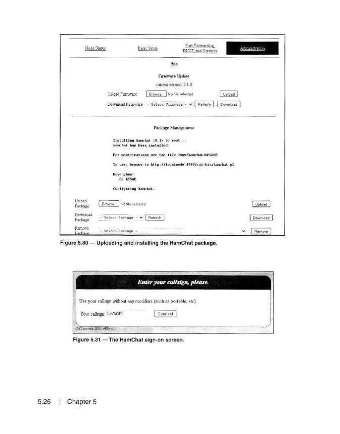
5.26
Upload Package
Download
Po11 F orwarchng DHCP, and Services
CWTent version 3 I 0
Upload Fumware I Browse_ I No Me selected ~
Download Fumware - Se l ect ru:1111e.rt - v I Refresh J Download
Installing hamcMt ( 0 . 1) to root . han:h.at has beeR installed .
For n>ditications see the file /'nm'r/h.an:hat/Rf:ADME
To use, brouse to http: //localnode: 1080/c'li -bin/han:'hat .pl
Have iihun!
de J>E5J>E
ConfiquriruJ hlurchat,
I Browse_ I No hie selected
Package - Sel ec t. Pack aqe
R~ovc - Select Packa ge
Figure 5.30 - Uploading and installing the HamChat package.
E11ter your callsig11, please.
Use your callsign without any modifiers (such as portable, etc).
Your callsign KWSGPj I Conned J
(C) CopJTl(!hl 1!112. \SHICI.
Figure 5.31 -The HamChat sign-on screen.
Chapter 5
I Download I
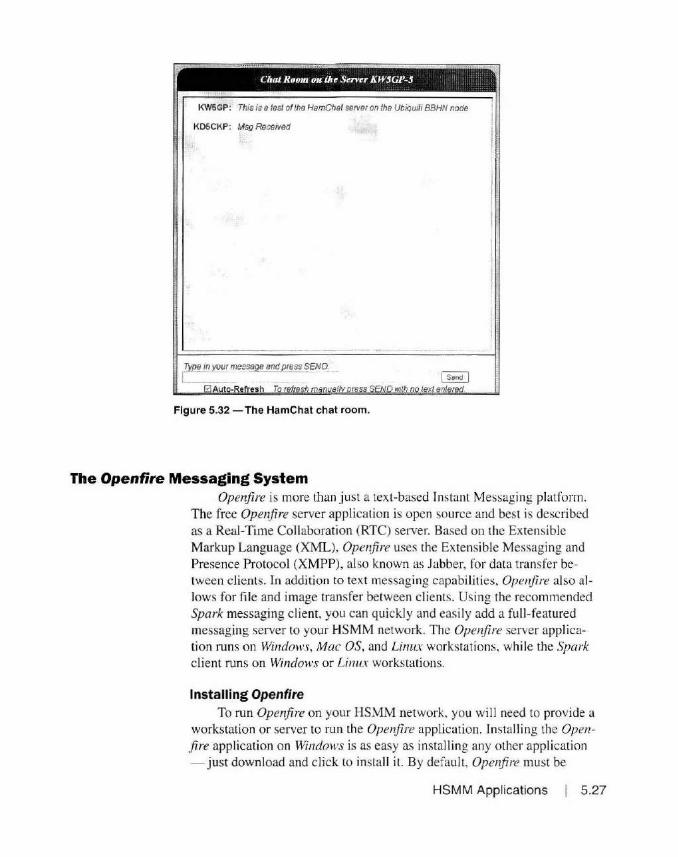
KD5CKP: Msg RecetVed
Type in your message and press SEND. l___ -
Figure 5.32 - The HamChat chat room.
The Openfire Messaging System Openfire is more than just a text-based Instant Messaging platform.
The free Open.fire server application is open source and best is described as a Real-Time Coll aboration (RTC) server. Based on the Extensib le Markup Lang uage (XML), Ope1~fire uses the Extensible Messaging and Presence Protocol (XMPP), also known as Jabber, for data transfer between clients . In addition to text messaging capabilities, Openfire also allows for file and image transfer between clients. Using the recommended Spark messaging c lient, you can quickly and easily add a fu ll -featured messaging server to your HSMM network. The Open.fire server app lication runs on Windows, Mac OS, and Linux workstatio ns, while the Spark client runs on Windows or Linux workstations.
Installing Openflre To run Open.fire on your HS~M network. you will need to provide a
workstation or server to run the Openj ire application. Installing the Openfire application o n Windows is as easy as installing any other application - just download and click to insta ll it. By default, Open.fire must be
HSMM Applications 5.27

Setup - Openfire 3. 10.3
Welcome to the Openfire Setup Wizard
Tht~ .,.,,,n 1nsta!I Openfirc on your complJte:r. The wizard \'\•ill lead vou 'rep by step thrOUQh the 1nsta ~a tion.
Ciiek Next to contmue:, or· Cancel to exit S!'tup.
started manually each t ime your workstation or server reboots, but it can easily be configured to run as a service that will start au-tomatically. Figures 5.33 and 5.34 show the basic process to install Openfire. Before we conti nue, we want to configure Openjire to run as a service. That will allow it to start automati-cally when the workstat ion or server is rebooted. To do th is in Windows, open up a command
Figure 5.33 - Install ing the Openfire messaging server.
prompt window and browse to the bin folder in the Ope'!fire program folder. typically C:\ Program Files (x86)\0penfire\ bin. At the command prompt, type:
Openfire Openfire-service /install
and then Open!i:::e 3 . 10.3 (Dec 19, 2015 5:41:1.5 J..MJ
Ad?:u:l ccn5ole li.s'te:unq at.: Opentire-service /start ht~p: ; / lo:5yp- l: 9090
ht;.t.ps : / • k\-:~gp-1 : 9091 to install and start Ope11flre as a service as shown in Figure 5.35.
Looking closely at Figure 5.34, we see another issue to deal with. Openfire has the ability to encrypt the administration console as well as messages between cl ients. You need to d isable the encryption functions to ensure that your Open.fire server is FCC Part 97-compliant when installed on your HSMM network. We' ll take care of that
Figure 5.34 - Completing the installation of the Openfire messaging server. once the initial setup of Ope1~fire is com-
5.28 Chapter 5
plete. To complete the initial setup of your
Open.fire server, use a web browser to browse to the IP address of your Ope1~re server and port 9090. In my case it's 10.242.255.97:9090. You will be asked to select the language to use, then you will be asked to configure some basic server settings, such as domain and the encryption key as shown in Figure 5.36. For the domain, you can use your HSMM node name, or any o ther name you desire. At this point. you have to enter a Property Encryption Key before you can con-

Figure 5.35 - Configuring Openfire C"P•·og>'am Piles <x86),0penffre">in)opcnfirc-oervicc /in s tall to run as a Service. Install ed ~e1·vice 'Openfire'.
C;,P1•09t•afl\ File s (x86),0penfire, bin)ope nfire - service / s ta1•t Starting service 'Openfire ' .
C" P,.ogt"am Pile s (x86),0penf ii•e, bin)
(j openfire·
Salup
Setup Pf)91HS
iiiC ..,_.nQWgot s. .. cuon
• S."'•r S.Rfn01;
oaia~•Stlll'IOf
Pmtle5'i.itGs
IOnflN.tounl
tinue. You can put anything in here you want - we'll be disabling the encryption as part of the final confi guration of the Openfire server anyway.
Next, you will need to select the type of database the Ope1ifire server will use to store user information and other Ope1ifire settings. Select the EMBEDDED DATABASE option as shown in Figure 5.37. This is the quickest and easiest way to setup the database on your Ope1!fire server. We really don' t need an external database server to handle the number of users we can expect to use Ope1lfi1Y! on our HSMM network.
Next, configure the profile settings. Unless you pl an on running a Lightweight Directory Access Protocol (LDAP) server as a common point to store user names and passwords, select the DEFAULT option as shown in Figure 5.38.
Finally. it 's time to configure the Openjire system Administrator account. Enter a valid e-mail address and select your administrator password as shown in Figure 5.39. When you complete th is screen. you will be asked to log into your Open.fire server administrat ion console . When you log into the Openjire server console, you will use
server Settings
OoN•n !KWSGP I
"<!11W1 Con901tPott -909:>
secu1•Adm.n Comole Port ' 9091
[ ...... .
Figure 5.36 - Setting the Openfire server settings.
HSMM Applications 5.29

O' openfire·
Semp
,l\11ngu.ioe Se~cuoo
.,/Server ~ttJOgs
• DataNS•~IUft2\
<>te'I• S-tw~t.
Database Settings
f~clO.ttlll.ne v stc .J'l t!""'*:J:le'l -:iau::aw p;:i .. .,1~ :i1 hSOlOB lhi'-OOIJO" 1~1,11-es ro e•l"r 111 ~~tuincun'li;;t.iil • :in ano "' ..,_en, 1.a11o1111tuo ancl "'~ c1110 •t "ti••~· II lt t SflOl ... ~ 1!ot'"'11r>e e~ cl r'°'b'"""'"'• atal\ t•tf'•"t<11oa•,;11i ne
Figure 5.37 - Configuring the Openfire database settings.
0 openfire·
Se1up
.('[)1tabn e ~n:ToQ\
· ProrM Serungs
Profile Settings
Ow..cl<lfy Se1ve1 (LOAP1 r•.a;•;rt .. .., _. ~ .. "~'• y• .......... ~ a""'-'·":' ·;,<to'.~· ~ .. +:.>"iP .1S•";t ~lC"' r":::L.><:• • .. t.f>·' ,.,._1 J'"''t'li .1·• t•:;·e'!l r r"!'01:~10r, .lnc: o-ta·eo.u,.>a.c"-'• t.lor•1tp;tcellr11e~i110n lf'~ra·e" .., a" t· ·\~r--:c • J•\;a·1 r~·a ai~i 1,,.~·s .l"-l Jf ).1; s t. •:to c~ ea ::1 ·t-a1 •c,...;. t .11•cat t ~tartt>Ait • .... 1 a·~ t e w>t"-:1 't• ;a..itne.,:it.n1~ vs-t1\ >e.u.e ::t h lir• MJ'. C.~iiJ'$<':lia ~ J : · r '9~t " •v;i .. •to
Figure 5.38 - Configuring the Openfire user profile settings.
O' openfire·
Setup
.tl angu.age Selec.lion
.IStNt'r ~tffing:f;
.fDIUll>HlfSefUngs
/Pl'OflltS.I~
AdmWIAU.(lt,lnf
Administrator Account
['l'lefU llr!;"\ ".;1~ $11~1'1.Nn~<'lt<...O:••'ll••"''"'~"",....,1 ¥.In.I' 0@-•::4 tt'i•~l>Cl'IOO'MJ'O"'"•Ol'1 101tnt "'cto.1nl1t1~,.¥1"10l tl•ee1st, g11tss.O··IOft•~ ~ • u 1,.. :ti.JroW•'\•~n:; Oll"·J :•l"IU•.,,,..~ ,. ,.., , :11 t::.1\2110t'Ul'"l..,..,, '~"( :i ., s~11::1 1t>1., .,.,.o,r 1~11 "'"y''"•a.Jt~P ,our il ~l'ln «tOt."' lft\llkl•~•,...u..rsl
N~Va1i,,w<lld: •••••••
CUllfirm l'OU -..d: . ~-•• -•• -•• --
li'@ijl@tfi ~
Figure 5.39 - Configuring the Openfire server administrator settings.
5.30 Chapter 5

tj openfire·
lhe usemame "admin" and the password you selecled. The basic configuration of your Ope1~fire server is now complete. Be
fore you start adding users, it 's time lo deal with the encryption issue. To disable the SSL encryption. selecl the SERVER SETTINGS menu under the SERVER tab from the main menu and then select SECURITY SETTINGS.
Here, you can disable the old SSL and TLS methods of encryption as shown in Figure 5.40. From the same SERVER SETTINGS menu, select the CLIENT CONNECTIONS options and disable SS L client connections as shown in Figure 5.41. Your Openjire system will now use no encryption for any of its messaging functions and you' re good with Part 97 of the FCC rules.
At this point, you are ready to add users. You can either add users from the Openfire Administration Console, or you can allow your users to create their accounts on the system us ing their messaging client. I find that it's general easier to let your users create their accounts. That way they can crcale their own password and get slarted immediately, bur this may also create a security concern, allowing unauthorized users to create their own accounts on the Openfire server. The choice is up to you, but in this case I'd lean toward allowing the users to create their own account.
-~t~':?
.-.~r-..i-n ... ~
11:::11 UsusiGroups Se:nlon• C roup C hat Plug ins
Pfoi te Sernl'll),
C~1r\.IC.onrie'llOO~
Ser.11r 1D Se-rver
Eti.rn.i Componenr~
ConnecllOn Manaoel"i
HTTP8'ncWlo
M~UP4Mat
F\fOIM"IOOll & lOOll"I
AtWVfCe Polio·
C>Ar.Mesu~
trMJn•1wc111Polcl
Pnv.iieJa~ Slot.JO<!
• 5t Cl.lflrY Stn1nos
Corno1u.S>onse:ll1'Qt
F"11efranslf1Sc!~s
St~hSer•<-t Prootnet
security Settings
Ctknt Connection Secu rity
'· ()pt!ONll ·Che ... :sma, ttin"MKllO f'I~ MIWI UMIW)ioetuted t CNWK.ton1
AequileO · Ctencs t an !lnt1 '~nnecl ti lt.e ~~ util\O MCu1.a colM'leC'On'
Cll3 SSL .-.ct-oa • NctAiallaDle ..... A1aiqollt
TLSM4tl!Ca • N::>! A"2L1ttlf' v Otit::infl H.e:iu11e.i
St rvt1 Con neclloP Stclllit)'
()p('°"'l · Co!Vlect.~ns Ofr.. t~n wr1·tr~ ~ , use ~•:u1eo ~onr.o, 1>on1
Ru1~11•C1. r.oi~ttcttnr.s oet1t.tt"t ''"'" 's 111"'' ''' 1.1H 1-t<u1£1a connt!tll~ns
Ser,•i 01alba u N~t .:r,,-;11zao·t • •wa~JOe
TlS INlflO' 1j • 1'1::1 .:r.~11iUl':l • ;: C):)')Qf\Jj
4'c•c:lw~neor~"t\i:a!es ~l\'•f ";1a":la~· :i~l.S~no,,.,a4 a~
Figure 5.40 - Disabling encryption on the Openfire security settings.
-
HSMM Applications 5.31

0 openfire·
F'n:r.1e Se~..,~~
' ci .. n tConMCtlOt'1
Hl"Slfl':lirr.~
1i.1a11a~Jc:e.i~s
Q•9~:-•tx1"1 l -1>,1r
=!•w...rtePOihO: t
Q"ill" .... 'AHS3:JH
1,lt JS1Y,)e ~1t.P-:•ty
P.• ,;a't O.J1.;1S~1¥,1t
St:un!';S'll-:.n,,11
Str.111 Ctni'\ta:1u
•·~ T~r5'!'rS<o:t·;s
~l'I'~ .. ~. ~· ='"'.'-:+r"'U
' .... --~.··~ -~-· .. _.,~ ... " l.i?WMr'
Client Connections Settings
l..H ~ 'Cl"n\ :+Yw IO ;:on"IJi.lf l'tJ• AJ.rr'P :1 .. r1' ~~r,.,.;t:- .,,., ,.,,pr: 1:ir-1 r t'I•!! prt\·Ct.:I ~11'11 ur.t• ~«i ~ ;:a., l ~ (~!•''""' tne :1 .e~tse~~;irs! ' J;ta! l'fl t.J'ritrt1 CC"r'°'i.3:Clr>1•1f<•<!'
1,;ll9"1'P":I" <7;:,?.
3'> (-,11:._, t'IJ :J•O
"' eo.r·tt-~•"~".J¥' ~1.•"-PP . ....,, • .;,,.•,·t.:> • •""•1"11 .. ·• 41• o.e·-: ~'.!'t, oi• t c~trr.e.»J Ci.t·')-.r.. .. nc:"li.;s..;:" a •ee..ts~ .. --.:.· 1~ .. 10otr••t?t>:k:t.-."f' ... T t "l'"l'~;,-~;I _ .. ..... ..... .,~r 1:w .,. '1,lfP l('f-0: ~:>:':lo"'it:)i,r•t\J l:l tra1,•u:.>:i'1:10·t~IAU 1'1 !lff"l ,:0~'\'"'C·!-t.:=.>Gr.t"t ~·:>:>:>it\)ta:A$: ·· M.."f.1 •ttJ·n ~..,..-:Y ..... :., ,.,... • • ~~··~:-,.,."'~Q
• <;foo.-.• a r , ,,1&:0> ~•"l '~J,.f'il'v .: ... 11'1~
Ct "r"H-.i ~l.'»" P ,"\il •r:Jv'':S~oCl·f: ,.n:i,
Figure 5.41 - Disabling encryption on the client connection settings.
~r1< Contacts Actions Help
kw5gp 0 Online -..
1!!1191£1
--------------~··-·----·-.. Friends (1 Online)
() Bdmin
: §; Contacts { P-? Conferences J
~ Searct-. tcr :.trier ceoc·e c11 tre s;;-:;;---
5.32 Chapter 5
The Spark Messaging Client The Spark messaging client (Figures 5.42 and
5.43) is Lhe recommended !RC chat client for use with Open/ire. Spark runs on Windows and Linux workstations and is a quick and easy installation. Spark allows you to chat one-on-one and in a conference-style sett ing. You can also send a broadcast to all users or selected groups of users.
One of the more powert'ul features of Spark is that it allows you to send files and screen captures to other use rs, without the need for a separate fi le transfer protocol (FTP) server or shared network storage device. One thing to be careful of wi th Spark is that it allows "OffThc-Record .. encryplion capabili ty, so be sure to have your users disable the OTR features in their Spark pref-
Figure 5.42 - The Spark messaging client.

admin
Figure 5.43 - The Spark messaging client chat screen.
;OB O 11 adm1n This is the SparK Messaging dient
erences lo maintain Part 97 compliance with respect to message encryption.
That's al I there is to it, you now have a full-featured messaging server runn ing on your HSMM network. '.'Jext we' ll gel into the more standard things such as web and FTP servers.
Standard Internet-Style Applications and Services
ClearOS 7
Traditionally. when you think or Internet-style servers. you think of web and ti le shari ng servers. Naturall y. these are applications that you may want to run on your HSMM network. To do this. you typically run these applications on a Wi11do 11·s or Li1111x server. However. setting up these applications can be complex. and in the case of a Windml's server. you would also need to buy licenses for the Wi11do11 ·s Sen ·er operating system.
Li1111x is free. but often fi guring out the Li1111x distribution that you want to use is overwhelming since there arc so many to choose from. Fortunately. there is a Li1111x distribution that is ta ilor-made to do exactly what we' re looking for and it's very easy to install and manage. While you can use just about any version of Wi11dml's Sen·er. or any Linux di stribut ion to provide applications and services for your HSMM network. we' ll show you how to add these applications using the ClearOS Li1111.r distribution because it's so easy to install and configure.
ClearOS 7 is the latest in a long line of easy-to-use Li1111.r distribut ions from ClearFoundation. They offer a paid Business version. as well as free Co111111u11ity and Hn111e editions. We have been using the free Co1111111111i1y edition in the Miss issippi K- 12 school environment for over I 0 years, and at one point, more than hal f of the 152 school dis tricts in the state were using ClearOS as their firewalling and Internet content filter solution.
HSMM Applications 5.33

Insta ll Cl earOS 7 .1. 0
I often refer to the ClearOS solution as a "Swiss Army Knife for networks" because of its versatility and ease-of-use. ClearOS is extremely easy to set up and manage . In fact, you can build a fully functioning server with web, Ff P. Internet content filtering. and whole host o f other features in under an hour, even if you don ' t know anything about Linux at all.
Based on the 64-bit CentOS distribution of Linux, C/earOS 7 is designed to be a turnkey application server, with everything managed usi ng a web graphical user interface (GUI). All of the applications can be installed and managed using the web GUI, meaning that you will more than likely never have to deal with the Linux command line once the installa ti on is complete. You don't have to worry about things such as package dependencies, find ing the right packages to install and edi ting configuration tiles to make things work. Everything you need is built in to the C/earOS Marketplace applicat ion on the server.
Don' t let the term "Marketplace" scare you. ClearOS has always been a strong supporter of the free Open Source community. In fact, their statement regarding the Community edition is : "Free now, free forever." They also state that the Community edition is "Intended for experienced Linux admins or those who like to 'tinker' :· That sure sounds like the definition of a ham to me. The majority of the applications in the ClearOS Marketplace arc free and install with just a few mouse clicks. The installa tion and configuration for many of these applications is clone almost automatically, with only minor additional setup needed to configure the application for use.
ClearOS 7 offers a wide variety of applications and services that we can use on our HSMM networks. In fact, the list of features is a long one, including web. file transfer (FTP), e-mail wi th antivirus and antispam, fire
wall , content filtering, intrusion
ClearOS 7.l. 0 detection and prevention, DHCP and DNS server, NAT, VPN, NTP, LDAP, media and file server, and
Tes t t hi s media & install ClearOS 7.1.0 database serve r. It even includes the ability to synchronize with the onli ne storage service Dropbox . All of these features are easily in
Troub leshooting
Aut m11atic boot in 57 seconds .. .
Figure 5.44 - Starting the ClearOS 7 installation process.
5.34 Chapter 5
stalled and managed using the web GUI.
Rather than get into every detai 1 o f every application available for ClearOS 7, I recommend you vis it the ClearOS and ClearFoundation websites. We'll focus in on

c:learOS
ClEAROS 7 l 0 IN S TAlLATION
&!I) ••
WELCOME TO CLEAROS 7.1.0.
W hat tanguagl! w ould ·1o u l lk.e to u~e d\11n 9 thf tnstaUat!On ptO(t'\5 1
English English )
Afrft.u~ .~I t1kJ.lff
" ""1:i: ~n•h Ill
~,.J I
~-:.~;;
A o;r111."1r"l( 1 · ' ·Ill.I' '
b e'1 aD,.l'. <_.<i l : I.' I 11 .J .... " ~
E.b/1111µt .. t' lh1l,fln1'""
... t-i1• L).'!f
0
£ng\lsh (IJ11t•d StAU!<)
Ef"1911Sh IUntrd Kingdom I
Enqti:r.h (lndi..}
Engl ~h 4-u!.tl all.ti
£nqt.,h (C .tNda)
En9l·~h (Otm\,Uk.1
En9 .. 1n {:rl'l.')f'le1)
E.nq l1st1 l Nt \'• le.il .ir~)
Eng l1';r. lN1qcr1.1:·
lng l1s,r-, :tt n"'j KCll(} ~ ol.R Chin.:1 )
H "lp'
the primary applications you may want to use in your HSMM network over the next few secti ons, right after we go lhrough the installation process for ClearOS 7.
Installing ClearOS 7
Figure 5.45 - Selecting the installation language.
To install ClearOS 7, you wi II need a workstation or server to install il on. Thi s can be almost anything that has a 64-bil processor, al least I GB of memory, 10 GB of hard drive, a DVD dri ve. and a network adapter. As you can see, it doesn't take a whole lot of computer power lo bui Id a Linux-based server. I rec
INSTALLATION SUMM ... RY ( l.(AROS 7 l 0 INS"Tl\:..l Al 0/\. ommend a minimum of 2 GB of memory and at least I 00 GB of hard dri ve space to allow you to
ei • • t<tlp '
~ledrOS LOCALIZATION build a server suitable for Ama
YSTEM
DATE & TIME
LANGUAGE SUPPORT
Engflstt {Un red Sri res}
INSTALLATION SOURCE
Loalmedt.J
KEYBOARD Erw;t,sn (U51
SO FTWARE SELECTION
INSTALLATION DESTINATION KOUMP
teur Radio HSMM networks. The choice of using a work
station or server is up lo you. The main difference between a server and a workstation is that a server is designed to be more ro-bust and reliable than a worksta
Figure 5.46 - Configuring the localization options.
tion. often incorporating redundant array of independent disks (RAID) technology. RAID allows for the fa il ure of one or more hard drives. depending on the version of RAID used.
From here on out. we' ll refer lo the workstation or server
you plan to build simply as a '·server'' to keep the confusion to a minimum. For most applications you will need only a single network adapter insta lled in your server. However, if you plan on using your ClearOS server as a firewall or Internet content tilter, you wi ll need a second network adapter because the ClearOS server wi ll perform the fu nction of a
HSMM Applications 5.35
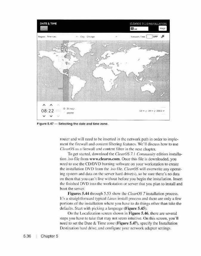
DATE & TIME CcoAROS 7 : c l"JSTA_LA ~1or'
Ill ~ Ill v C•ty Ch1c.:.90 N ctworl< T ime D off J)
08:22 0 24 ·hour
12 v / 19 v J 2015 v
v v
Figure 5.47 - Selecting the date and time zone.
5.36 Chapter 5
router and wi ll need to be inserted in the network path in order to implement the firewall and content filtering features. We' ll di scuss how to use ClearOS as a lirewall and content filter in the next chapter.
To get started. download the ClearOS 7. 1 Community edition installation .iso fil e from www.clearos.com. Once this file is downloaded, you need to use the CD/DVD burn ing sort ware on your workstation to create the installation DVD from the .iso fil e. ClearOS will overwrite any operating system and data on the server hard drive( s). so be sure there's no data on them that you can · 1 I ive without before you begin the installation. Insert the finished DVD into the workstat ion or server that you plan to install and boot the server.
Figures 5.44 through 5.53 show the C/earOS 7 installation process. It's a straight forward typical Li1111x install process and there are only a few portions of the installation where you have to do things other than take the defaults. Start with picking a language (Figure 5.45).
On the Localizati on screen shown in Figure 5.46, there are several steps you have to take that may not seem intuiti ve. On this screen, you'll need to set the Date & Time zone (Figure 5.47), specify the Installati on Destination hard drive, and conli gurc your network adapter settings.
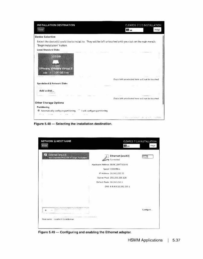
INSTALLATION DESTINATION c JARG:" 7 1 • NST.\c.A-'0'
Don• ~ -I
Dolllce Selection
Select the devlce(s) you'd like to insta ll to. They will be left untouched until you click on the main menu's
"Begin Install at1on·· button.
Loe.el Stende ,-d Disks
.-~~OGIB
~.. ~.-. VMware, VMware Vlrtu:al S
sda /~ 3:_0~-GIS fre~ _
SpecW.l.ized & Ndwor k Disks
Add a disk ...
Othe r S tor39e Options
Partitioning
0 AutornoJt •cally c.onfigurc partitioninq.
Dir.ks lt!fr uos~/ea~d h~r~ w ill not be t oucll rd
Disks l cfr unsrfuud here will nor be tcua1ed
I will configure p,,rt it1oning
Figure 5.48 - Selecting the installation destination.
NETWORK & HOST NAME CLEARC, l ! ,, 11\b T'<LLAW>I'
-D~;,. ~ Ill
JJ Ethe•net (ens33) lnt•l Cerporubtl PR<YlOOO HT Sh9l'" Port ~u
I + - r
.£.J Ethernet (ens33)
~Connccttd
H•rdwart Address 00 0C 29:F7:(15 ·95
Spud lCXX> Mbls
IPAddrus 10.242 255 SS
Sulxirt Mask 255 ZSS 255 128
Def"ull Aoua 10 242 255 1
ONS 8 8 8 8 10. 24 2 255 l
Conft9urt
Figure 5.49 - Configuring and enabling the Ethernet adapter.
HSMM Applications 5.37

CONFI GURATION CLEAROS 7 l.0 IN STALLATION
si •• Help'
cit!dl'OS USER SETIINGS
RO OT PASSWORD
Figure 5.50 - Configuring the root user settings.
ROOT PASSWORD Cl r AROS 7 1 0 l~J ST <\LL A Tl ON
m;!I ~ 1111 Th e root /JI CC o um I!. ustd for adm1ni ~tering th!! ~y~ tem Enter a p;,s ~wcrd f or th~ root user
Roo t P.i '..~word I Empty
Confirm
Figure 5.51 - Setting the root user password.
5.38 Chapter 5
To select the Install ation Destinatio n, you'll need to select the hard drive you wish to install to using the screen shown in Figure 5.48. If there is al ready data on the disk. you will be given to option to delete the partitions and reclaim the disk space before continuing the installation. Unless you 're familiar with Linux. just use the default to automatically configure d isk partitioning .
The trick iest part of this screen is configuring the Network and Host sett ings. The installation process defaults to using DHCP, whjch is fine while you build and configure the server. You will be changing the JP address to a valid IP address on your HSMM network at the completion of the installat ion process. However, you also have to select the on box in the upper right hand of the screen as shown in Figure 5.49 to enable the ne twork adapte r. Unt il you do this, you will not be able to comple te the installation process.
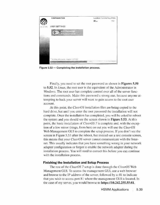
CONFI GURATION CLEAROS 7 l OINSTAllATION
E!l •• Http '
1 k 110':> USER SETTINGS
Figure 5.52 - Completing the installation process.
Finally. you need to set the root password as shown in Figures 5.50 to 5.52. In Limn, the root user is the equivalent of the Administrator in Windoll's. The root user has complete control over all of the server f unctions and commands. Make this password a strong one. because anyone attempting to hack your server will want to gain access to the root user account.
At this point. the ClearOS installation files are being copied to the hard drive. but until you enter the root password the installation will not complete. Once the in stallation has completed, you will be asked to reboot the system and you should see the screen shown in Figure 5.53. Al this point, the basic installation of ClearOS 7 is complete and, with the exception of a few minor things, from here on out you will use the C/earOS Web Management GUI to complete the setup process. If you don' t sec the screen in Figure 5.53 after the reboot. but instead see a text console screen, this means that your ClearOS server cannot communicate with the Internet. This usually indicates that you have something wrong in your network adapter configuration or forgot to enable the network adapter during the installation process. You will need to co1Tect this before you can continue with the installation process.
Finishing the Installation and Setup Process The rest of the ClearOS 7 setup is done through the ClearOS Web
Management GUI. To access the management GUI. use a web browser and browse to the IP address of the server, foll owed by a : 81 to indicate that you wish to access port 81 where the management GUI is located. In the case of my server. you would browse to https://10.242.255.55:81 .
HSMM Applications 5 .39
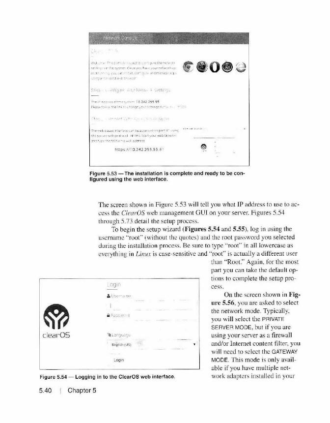
clearOS
f· •. _ l· - ~·1· 1· -·· :; : r'. J,•: ··~·.•:j · i;, . ·.'! '1·.11.r;::: ; her'i;-:'v,' .•I..,
.;,r~ rw1r, r 11 ;t·-ir, syst1•1~i C'w.:t> ·JnL h:i.··~ i.'Ol1r :-i t>t ':" o::~I< up
;~ ~+-.1 .-\ i ~ > ~.:: U ' ., .
f ,
Tf'"&i ,,.,~t·r- :Jn.':>t"'..: ir· ~t;-·f3,·t· ~..or I).~ aC ( >'~""""l Of> j:'<)r. 3 ' ·1•_.W!j
lf'e S•Xlrr t• \\·t•h pr r); :.1t:.il HTTPS ~,t;nt •1ou r W'"b t_-.1· ,~ • \'1';•- 1
:.r•"J • ~r" tt'i-:-'cll ..... , ,. ".: \'. d .:lddro;:-;o;
https: //10.242.2 55.55 .81
Figure 5.53 - The installation is complete and ready to be configured using the web interface.
The screen shown in Figure 5.53 will tell you what IP address to use Lo access the CfearOS web management GUI on your server. Figures 5.54 through 5.73 detail the setup process.
To begin the setup wizard (Figures 5.54 and 5.55), log in using the usemame "root" (without the quotes) and the root password you selected during the installation process. Be sure to type " root" in all lowercase as everything in Linux is case-sensitive and "root" is actually a different user
EngB~h(tJS)
Login
than "Root." Again, for the most part you can take the defaul t options to complete the setup pro-cess.
Figure 5.54 - Logging in to the ClearOS web interface.
On the screen shown in Figure 5.56, you are asked to select the network mode. Typically, you will select the PRIVATE
SERVER MODE, but if you are using your server as a firewall and/or Internet content fil ter, you will need to select the GATEWAY
MODE. This mode is only avail able if you have multiple network adapters installed in your
5.40 Chapter 5

ClearOS Wizard o Install Wizard -
~ Registration
0: Configuration
0 Marketplace
8Flntsh
Gelling Started The Install \\ t11ard guides you through the- steD!" to get your C1ear0S sysiem up and runn1nq After tlie t)as1cs are conf1gL.red, y.::iu !I i;;et a .::t-:ance to go throllgh the C1carOS Marketplacew11ard to install apps.
If you neer..1 ass.1 stance wi th mstal l.1t1on or co11l 1qurat1on, pied~ u!v1ew the ava il ~1ble help 1n the> w tzard. You CJn also find inorf' ~ n-depth helo o n lire;
• l·>~t.=i_ I :;i,101•.-:'
• UsH (,,n0 : _~
Click o n the Next button to cont nu e,
1 I
\-1 .. t1< r.- : t>r Ou l:"S ro~s.;•r
.i:it"C f c '>('," .... • c-~ ~::is ~-., ...
,,~..:.· ":e:Jt:;:y"'T'er: c•.: r-ar ..)~
C i. -: ,,_ ,,. 10 e.:in1 ~'>Clrt> or :,,_. ~l::>nnecf our "iOlut ion
Figure 5.55 - The ClearOS installation wizard.
ClearOS Wizard o Network Mode
< Network Sen1ngs
~ Registration
0: Configuration
b Marl<etplace
Iii Finish
Network Mode
ll!t s ;eq,'C>\.~ "ltt,,.,'01'. ..,p a. ... d ·unn1"lo;: Tne :;oft ... itr,.. •!. 1ttl!: ·~~. ~.:.i'tl ,. '°"' ·Oc::> -©-
:::orr g'-'r'"o1r 01~'>!1-enl "eh .. .:., ... •·=- ~·, =''€:'~e ~ e~t t ne t-e~-::iot ..:in~r- ... 1 •,.J1-:.:,c v
l'l~i
~ Private Server Mode
This mode 1s appropriate for s1anda1one
servers installed on a protected networ~.
for exanp•e, af'I o ffice netwo~k. The
fir ewall is d isabled 1n this moCe
v Pubhc Server Mode
This modE is «.ppropnate for sta "'Id atone
servers !'\Stalled 1n hostile erv ron-:ient.
i-or exa;role a d ata cente• or pub l:c
hotspot
Gateway Mode (Unavai lable)
Gateway mode is used to CO!'\t"\ect a
netwOfk of system~ to the Internet or
internal network. You need a.t least two
net work cards for this mode.
• •
• • Figure 5.56 - Selecting the network mode.
~ ~~
clear BOX
HSMM Applications 5.41
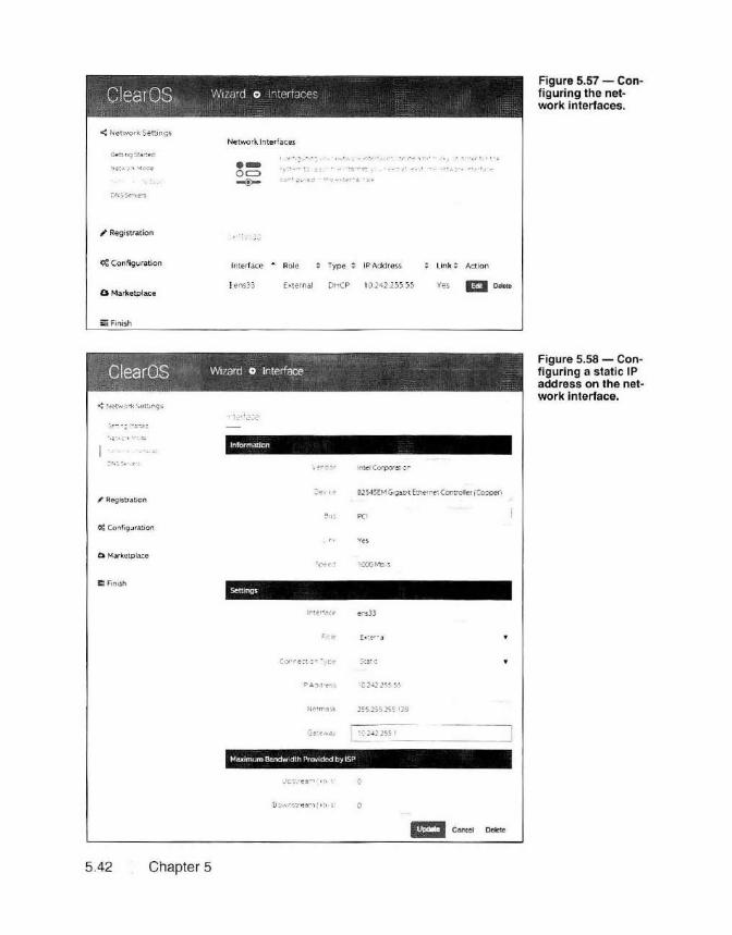
ClearOS. Wizard o interiaces
<Networ k. Settings
~ Registrat ion
0: Configuration
Network Interfaces
·O c::> .-:!>-
\ · ~ : : "; j
Interface • Role Type ~ IP Address
l ens33 External DHCP 10 242-255.55 b Marketplace
!5 Finish
., ..... ~ ., - -
ClearOS Wizard o Interface
lnformct.t1an
• .· ~ ~ . • r ' ' . .,;
Li nk ~ Action
Yes mo .....
~ Registration Je~ ., 8lS45EMGQdO'tEtm-irctCortrolle'(Co~)
al~ PO
0: Configuration
D Movkctplace
·0 2 ~22ss :.s
2~S2SS 25511EI
Maximum Bandwidth Provided by ISP
5.42 Chapter 5
Figure 5.57 - Configuring the network interfaces.
Figure 5.58 - Configuring a static IP address on the network interface.

ClearOS Wizard o lmerfaces Figure 5.59 -The network interface configuration is now complete.
< Network ~ttings
'Registration
0: Config\Jration
a Marketplace
!I Anlsh
Network Interfaces
·Oc:> --<!:-
( e r' g ... r ns :-rui..r • t>~~ .. ,;:,rl.: .,lt>r'&.\::?S ' A•l [)~ ~: t fl •.I./ 1~- ~·d"'' !~,. t11.,:o ~-, ~:.:: r"' D
r ,;oa<r tr .o- "''\:i't""" ' ,c,_, .. ,..~ ~ .:.t • ,;ia~! ::;n,: .,elw~r~ ~-ti-rl ~ c~ ~;:,~ii:::-· · .. -: · : ··e
... ~ liH'4.' r::ii,;
Interface ... Role Type ; IP Address link: ActJon
:ens33 External Static 10.242,2'.JS-5 ) Yes Im De!O?te
server. In this case . one of the network adapters w i II be designated as the External Interface and you can select the mode of the other network adapters to either External , DMZ or Internal LAN mode. Since the fircwalling
and content filtering options are bit more complex. we'll deal with them separately in the next chapter. but your firewall and content fi lter server
can also host any applications you wish to install on your C!earOS server. For now. we'll select the PRIVATE SERVER MODE to build a standard appl ication server without the firewall or Internet content ti ltering opt ions and continue with the setup wizard.
Next, you are given the option to configure the ne twork adapter as shown in Figures 5.57 through 5.59. For the insta llatio n process, you can leave the IP address set to use DHCP, but rm fussy and prefer to set a
static IP address for a ll of my servers. In e ither case, this is a temporary JP address you will be using to build and set up your ClearOS server. The IP address of your network adapter will be changed to a valid IP address on your HSMM network when you' re done building your server.
As shown in Figure 5.60, the setup wizard will now verify that the Internet connection is good and that the DNS server settings are valid. If the DNS lookup test fails, go back and check your IP settings for your network adapter, as this is an indicat io n that the server cannot communicate with the Internet. That mi ght be caused by an invalid IP address, subnet mask. or default gateway setting.
The next step in the setup process is to select which edition of ClearOS you want to use. As mentioned previously, the Co1111111111iry and Hom.e editions are free, while the Business edition is a paid version with
technical support from the good folks at ClearOS. The Community edition
HSMM Applications 5 .43

ClearOS wizard o DNS Figure 5.60 - Configuring the DNS server IP addresses.
< Network Settings
~ Registration
O! Configuration
b Marketplace
Iii! Fln~sh
DNSServers
·o= ~
~ Success
~,::,._orof .; ... ·a'. ;:-:., ~ .. ~~ .. ·~t .l for y?-..r s~;l e ..... '"' u-=-! J'•S ... 1? ;1 ~,..,, :11 r~s
kAO:Cf'I" 'f:, ... -;~ -l ::·1.,:):; C'' $ ;el". e ' •:-: t;o;'. , o ... r 1f1"""':"""1 t,.O anc• •• --r rg f~
~J·1 i..~-eGxg e s :>:-.J:i.;:..,01 ~ .. 1•· SSB ~an~ 2 g .: ~
DNS lo okup succeeoedl
::.1· .s
ONS Ser.,er • i BB.8.8
')NS S"!r ver • 2 10 242.lSS I
Ill
has everything needed for HSMM networks, so select that edition as shown in Figure 5.61.
Even though it is free, you will need to register your ClearOS server online with ClearOS. Odds are you don ' t already have an account with ClearOS like I do, so you will need to set up an account with them using the link on the screen shown in Figures 5.62 through 5.64. Registration doesn't obligate you to buying anything, and you are even given the option to opt out of any e-mail notifications sent by ClearOS as part of the regis-
Community w 1ard o seecif.:crtrcr ~
< Network Settings
/ Registration
O! Configuration
b Matlcetplace
EFlnish
Thank You for Choosing ClearOS
:. ,_ \ ac ~v ns ar tr :: s-e .,.,-o f• ~e to t nk·""'
Help ~prea.C ;:•1e ""'<"<! ~nc share CiearOS Ho11•e
ld ~ 0"' '" t!"' JO .. r Ir €'f1ds ~~oJ fa.rr-i)'
BJs1ness Edmon
Profe s!.JOrrnlly su p 1--"'0r t <!'C: IT
olatforni f or bL.s.1ries~es wr.ov.<i.nt to m ·n 1" •Ze th.?
' 'Sk of co~·.nt rT:t'
Ill
(lo>arOSComm.Jn ty Ea.ton is svpponea by a commun,ly :-t volunteers donating their lime and ~nowledge via the C!earFoundatJon. Th is supvort model may no t b~ the b~st solwt1on for yo ur bus1nes.s c t 0 1g anisa.t1on Please cons.;cer a.H facto1s (ied 1ri:c.a.I skill , num ber of vsers, c at<' :;ens ti'lity. res auict-s et<.) when cons1denn9 usi!'lg ClearOS Co rnrnunity E:d 111 on 1n a ccmmemal. prnressionai, edocalH)nal or !arges-:.:ite d eplc yr.-1ent.
Figure 5.61 - Selecting the ClearOS edition to use.
5.44 Chapter 5
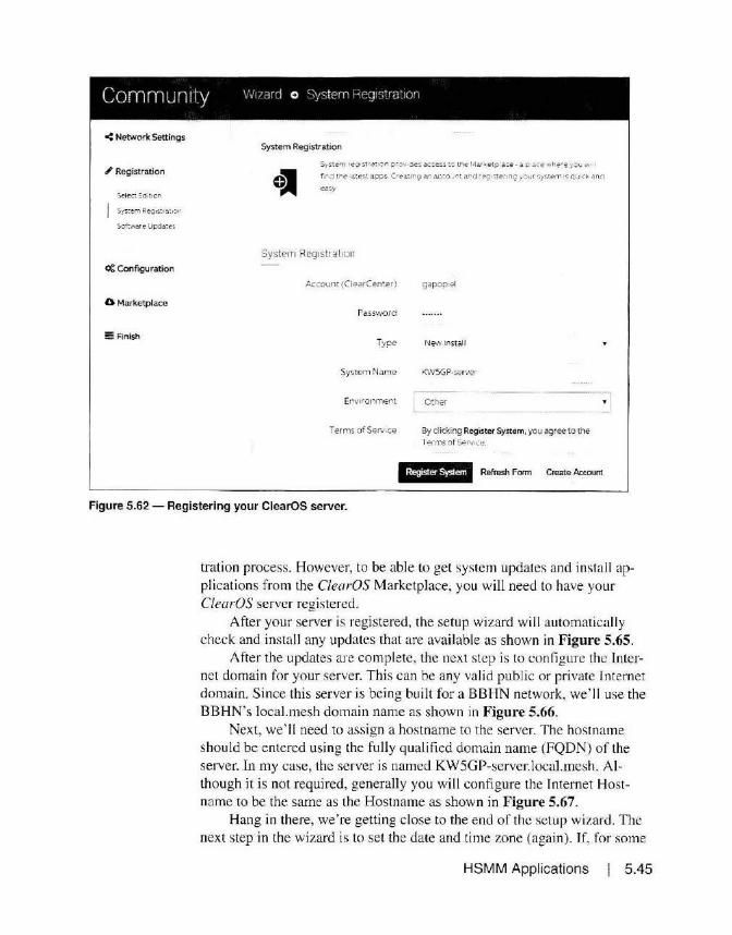
Community \!/1zarcJ 0 Sys tern Heq1strat10r1
< Network Settings
.I Registration
Sof:wore Upd~tes
0: Configuration
0 Marl<etplace
~Rnish
System Registration
System re91str-=.t -·:in p rov.ce-; ~<:ceo;:~ to the 1-!;u-;etp ace-.:. p .l(e .-..here yol,.l w
fird tr e 1a lest a.pp:;. (r~~tm9 an a.cco...,<it ~ ... d reg 1~e -1n;; youf !:.Y~tem ·s q u:ck and
Systern Reg1stral1on
Account (ClearCem.er) gapop1el
Password
Type New Install
System Name
Env1ro nrnent E ·---~
- -------
Terms o f Ser.nee By clicking Register System, you agree to the f erms o f Se-nbce
@Ari& Refresh Form Create Account
Figure 5.62 - Registering your ClearOS server.
tration process. However, to be able to get system updates and install applications from the ClearOS Marketplace, you will need to have your ClearOS server registered.
After your server is registered, the setup wi zard will automatically check and install any updates that are available as shown in Figure 5.65.
After the updates are complete, the next step is to configure the Internet domain for your server. This can be any valid public or private Internet domain. Since this server is being built for a BBHN network, we' ll use the BBHN's local.mesh domain name as shown in Figure 5.66.
Next, we'll need to assign a hostname to the server. The hostname should be entered using the fully qualified domain name (FQDN) of the server. In my case, the server is named KWSGP-server.local.mesh. Although it is not required, generally you will configure the Internet Hostname to be the same as the Hostname as shown in Figure 5.67.
Hang in there, we're getting close to the end of the setup wizard. The next step in the wizard is to set the date and time zone (again). If, for some
HSMM Applications 5.45

Community Wizard o System Req1strat1on
<Network Settings System Registration
~· Registrat ion Sy1tem rcgl~rc!.t or orov1~ !CCf!'S~ to t"'(" Marketol4ce · a ol~ce ..... ~re )'OU WJll
, . .,o tt-.a ~·e-;t ~c~~ -.,..<.ll'r'V an d.C.:cunt ari.:: r~ ~:e-r "'•J : . .-.,..,· ".::~le"TI ·~ qu11:k a"d
S~ e.;t Eo: or
Create Account <>:Configuration
Account Username gapop el
0 Marketplace Password
iii Finish Verify
E-mail Address kw5gp~ar rl n.>t
Country ur ted States
Subscribe to Mailing List Enableo • I 'Jew Version Releases i:t
New Marketplace Apps 1J 1
Beta Programs J
Promot ons ,j;
Mfi +"·!! Canc4H
Figure 5.63 - Creating your ClearOS online account.
5.46 Chapter 5
reason. C/earOS did not use the date and time zone settings you configured during the initial installation process, you can re-enter them again as shown in Figure 5.68.
Now we· re getting to the fun part. A t th is point. you can select and install your server applications as shown in Figure 5.69. I usually skip the insta llation of applications at this point and install the applications after the setup wizard is complete and 1 know that I have a fully functioning and configured server, but that's just me. You can either select and install your

Community W 1ZiYd 0 Syc;ter'l Req1strat:on
< Network Settings
' Registration
Software Updctes
0: Configuration
0 Marketplace
5! Finish
System Registration
5y~tem re91su a.t1on provides a.c:cc 5S to tile l··lar ~etp ace a p ,ace whe"e ycu .. .,.
f1 rd tne i ate~t a;::ip'.'.:. Creet.nQ Mi eccou"'t .anc r e.;i , ~e~ir.Q 1our <;;y~tern ;s q .... ".:K and
ea-:.y
System Rcg1strat1on
Status Registered
Account gapopiel
System Name KWSGP-server
External Hostname/ IP kwgpserver2.poweredbyclear.com
Hostkey 9afc 15944efe 1 d2ba7fdd1652c1 9f605
Software End-of-Life September 1,2021
Figure 5.64 - Your ClearOS server is now registered.
applications now, or after the setup is complete. The choice is strictly up to you.
Congratulations - at this point the setup on your ClearOS server is now complete. There are just a few more steps to finish the basic configuration. When you initially log into your ClearOS server, the web management GUI takes you to the Dashboard screen. The Dashboard is full y configurable, allowing you to display the basic system and status information you want. I generally don' t want to see a whole lot of information on the Dashboard since I spend 90% of my time on the other screens in the web management GUI, but again, you can configure your dashboard any way you desire as shown in Figures 5.70 through 5.73.
HSMM Applications 5.47

Community Wizard o Ava 1ab1e LJpoa:es
< Network Settings
' Registratior1
Software ~Dd~te~
0: Cor1figuration
b Marketplace
!!!!! Finish
Software Updates
• Nm•1 tt'tc.t yow netv:ork is ::onfig ureC. cri t ical L'pdates to the ::ore system an~ now
insta/lec:
Available Updates AME.\11 Package • Version
Firewal l 2 .1 .28· 1.v7
Firewal l · Core 2.1.28-1.v7
Ger1eral Sewr.gs 2 . 1.26-1.v7
Gener al Settings · Core 2.1 .26-1 .v7
Users 2.1.25-1.v7
Lsers - Core 2.1 25-1.v7
Figure 5.65 - Installing system updates.
Community wizard o settings
< Network Settings
' Registration
0: Configuration
Date ~ rid 1 m e
b Marketplace
:! Finish
lr1temet Domain
·Oc:::::> ~
S.e t a def at.. \ l n t~rne~ ,JO'"'"' a n ;or yo.,· syst~n ... ' o r exarrp;.;a example corn. 2y the
way , ··"'·e use- ·•1merret domo. r\'" nsteao of .ust Rcoma·n· 1n our teur .ino togy to .avo d
con:1..s.on w th "'~Yi ndo·•• S 001iia 1n s"'
L loca i rneshl _ ------------~
Figure 5.66 - Configuring the server domain name.
5.48 Chapter 5

Community V'Jizard o sen1ngs
<Network Settings
-' Registration
« Configuration
Internet Dom!.1,.._
a Marketplace
a Finish
Hostname
·-0~ ~ Seit1ngs
it is. t 1'ne tc oef 1 ne tt~e r.cstnarre fo r yoiJr system -iey Nd:t a m nut..:: wh} c o yoL nt!ed two hostnames? O f!en, tnese twc hostn-arr-es are the same, OLt p i.:a.SE f€3d
i::he hE?lp sect 1on for more 1nforrTat1on
Hostname KWSGP·serv er.!ocal mesh
Internet Hostname K\VSGP+server tocal_mesh
Figure 5.67 - Configuring the hostnarne.
Community Wizard o Date and Time
< Network Settings
-' Registration
« Configuration
0 Marketplace
iii! Finish
Date and Time
Settings
Many apps ano serv:ces requi re correct time zone 1n forn•at1 on and an ~Kc 1... r ate
dock, s::i :t s rn•oorta.nt that t is set correcHy
Date Dec 192015
Time 10:04:51 CST
Time Zone Amenca.·Ch1ca.go
Automatic Synchronize Enabted
RMI Figure 5.68 - Configuring the date and time zone.
HSMM Applications 5.49

Community Wizard o Marketpace ~
< N~tworli: Settings
~ Registration
0: Configuration
0 Mark.etplace
!! Finish
~tting Started
,, · ' ; , ~:.~~ • .-· , ·~'-- ~.~. <-1'~ '. t''.~ .. ~ · ··.- 1 • · '<' . ~,; "1<>'1.. -..:: ;::ta.~~ Yo ... ... I .-,nr: a'a.n; "' • ; .••.-.., · .,,, ·-• ·: ·.,:~; , . ...., ,. . ,-,, :oilc' • ~'I-'" ' l..1 ' ,,d·· ~;;- : -. ~·'.J ' •'."J r . ; 1 , , . ,., ~~ 1 1 1q;,;::;
If y0•. e1e 11~·.'i t(' i · 1 .-,;n.)~ o r p·e€'r to ( Qnt1 (/1..'l l ' the sy'::cm
by spe-<..:,fu.: l <i>k', i " :) 1-:r·.ent \JSers ' rom a.:..:e:z.1ng ..::rrc a. "I
1\rb s. :.: s ~t)~;i: r I <:"~ c .. t~\.:~ri ;.,~.;r<; ~~c i. ~.-l t:( t ! "'I~ ::p t ~fl
(I t'<'. ' ...:e11~.'0'' .:,·- .:_: :r,;- f..),-.,!• ~ -:.~""<:.':: ::;- · c_,r .. r'l.J'1 • , 'l :< •e .;i.
.·.Ct:-$~~-=: (,·"~~ Ph.· ~.;inr .;: 4~.;.:: · r:- r-p· -: · t' '· ~h.,'. ..... ! C!L. ~;.
-.; t:"!:• :::i ...... P _:in c 1_r,., ·• -j
D ."'µ 1ay~ gro.;.;ps c f <'lpp -<, b .1 'Mc'd c~n d. Cdtegor~ Cld5S1(1CJ.l on
'i)'":.t~m t..S.€~ 1n ttH:· rra,n n· ~·m .. . U yo·~ d•e fam1har w ith oas1c
11..-L;,0~ ~ 1:1g_ s-et'iCr t;;"m5 .Jnd f<1rn•1,<'.!r \\ •th th~ ( learOS
\~ri · • -::;:-. <:.C.;. > o::I '° ~ ' ' ·; •, ~ :1' · ; I
>" p :ri-:-Cl ~a· O'S :-~3 ;f'tple~~ "" .-:;uc. Y;:;~ can n s1a11 a1=os at
<'lr1; t ff<! oy r.a. '9"'' rig to 1h~ l·l.:n..<?t p iei:-e
SclOctea
Figure 5.69 -You can choose the applications to install on your server or skip this step and install the applications later.
o- ::1( RJJT
Community oashboard 01llir Iii
Q
lii'.J Network Status
!nstallaltation ..-,1z,11cl :;.omnfetc-fl System
. >1- 1 :· t r1.v .. 1 ~ ! ,... - -. or St:' e:t u·c- oera.r:
E§ .. 111/&1;5·§§ I
!i(J Reports
Figure 5.70 - Configuring the ClearOS dashboard.
5.50 Chapter 5
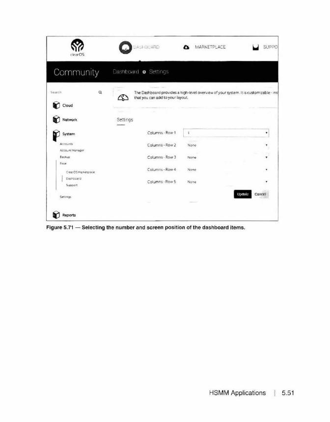
li'.J Cloud
t(J Network
f' System
AccounlS
Account Manao~r
l!-.sc.k.up
Supoort
il Reports
Q
QuA~H:-,ARu Q MARKETPLACE ~ SUPPO
Settings
The Dashboard provides a htgh·level overview or your system. It is customizable - ins that you can add to your layouL
Columns· Row I -- ·] Columns · Row 2 Nono
Columns· Row 3 None
Columns· Row 4 None
Columns· Row S None
Ill c ancel
Figure 5.71 - Selecting the number and screen pos ition of the dashboard items.
HSMM Applications 5.51

Webmin
0 MARKETPLACE
clear-OS
O DASHBOARD
Commurn:y _.,-. , , ·' ·
Q
~ Cloud
The Dashboard provides a high-level overview of your sy that you can add to your layout .
li('.J Network Seled
Widget Selection IJ System Select
System Shutdown I Restart
Users and Groups
Reports
.t.ccounl:;
Accou.,t ManaQer I eaclcuc Events. Last 24 Hours .. :.... . Process Memory Usage
Ooud Recent Software Act1v1ty
'
Oa'.ihbodtd
Suppo11
i'.J Reports
Figure 5.72 - Selecting the dashboard items to view.
There is just one more step to go before installing and configuring the appl ications on the ClearOS server. This is an optional step, but I have found that taking the time to install the Webmin application makes managing your server a whole lot easier, especially when it comes to uploading, downloading, and editing fi les on a Linux server. Typically Webmin is installed using the yum or rpm package installation programs in Linux. Starting with the more recent vers ions, Webmin has some Linux distribution-specific options that require the install package to know which version of Linux it is being installed on.
Unfortunatel y, with the current L770 version of Webmin, the ClearOS version of Linux is not one of the supported distributions, so using the yum or rpm package installers to install Webmin will fail and give an unknown
5.52 Chapter 5
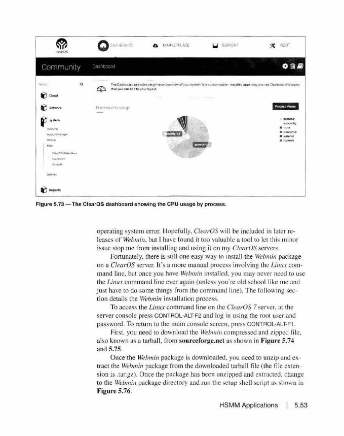
0.
Ii' doud
" Network
"' System
" Repons
a Ml1RKETPLACE ~ SUePof.l ·· ~ ROOT
The Dashboard provides a h19h·level oven11ew of your system. It 1s custorr.1za~e ·installed apps may provide Dashboard Widgets that you can add to your layoul
Pioc:ess CPU Jsagc eq.t§fh'
• ICUOS
Figure 5.73 -The ClearOS dashboard showing the CPU usage by process.
operating system error. Hopefully. ClearOS wilJ be included in later releases of Webmin, but I have found it too valuable a tool to let this minor issue stop me from installing and using it on my ClearOS servers.
Fortunately, there is sti ll one easy way to instalJ the Web111i11 package on a ClearOS server. It's a more manual process involving the Linux command line, but once you have Webmin installed. you may never need to use the Linux command line ever again (unless you' re old school like me and just have to do some things from the command line). The fo lJowing section details the Webmin installation process.
To access the Linux command line on the C/earOS 7 server. at the server console press CONTAOL-ALT-F2 and log in using the root user and password . To return to the main console screen. press CONTROL-ALT-F1.
First, you need to download the Web111i11 compressed and zipped file, also known as a tarball , from sourceforge.net as shown in Figure 5.74 and 5.75.
Once the Webmin package is downloaded, you need to unzip and extract the Webmin package from the downloaded tarball file (the fil e extension is .tar.gz). Once the package has been unzipped and extracted. change to the Webmin package directory and run the setup shell script as shown in Figure 5.76.
HSMM Applications 5.53

[root@l<WSGP -server - 111 cd / tmp [root@l<WSGP -server tmplll wget http ://prdownloads .sourceforge. ne t/webadmhvwebmi n-1 . 770. tar .gz_
Figure 5.74 - Using wget to download the Webmin installation package.
[ root~K\.ISGP-ser\.Cr - 1u eel / tmp [email protected]('1JC'r tmp Jtt w:Jet http ://prdow-n loods. sourceforge . net,1~ba.dMi O/t..cbmil\ - 1 . 770. tdr .gz --2015 12 01 17 :50 :12-- ht lp : ,1,1prdown loads . s ourc cforge. net/~b ... dmirv'-Cbtnin- 1 . 770 . tnr .gz Reso l ving prdo"1n loads . s ou reef orge . net CJJrdown loads. s ourcef orgc. ne t ) ... 216 . 31 . 101. S<J Connect i ny to prdown loads . s ourr:r.forge. net Cprdm.m loads . sourcefory t:! . net) :216. 31 . 101 . 5') : :80 ... connected . HTTP request sent , aWl'liting r esponse . 301 t'b\.ed Pel"manent l y Locf\ t i on : http: //down JoMts . sot1rceforge. nel / Jlf'Ojr:c l / wcbadmi 1V\..ebmi n/ l . Tf0/t..ebmi n- 1 . ·779 . tar .gz [fo 1 lowing J - - ZRlS- 1.2-01 17 :50 :13 h t t.p ://down loads . scmr1:efnr-ge . net/prnj1~c l/webadrni n / 1..1ehm liv t . ?70/l..lf!h"' i 11 - l . T/0 . tn r .gz Reso lv l ll!:f d rn.JH Lotl.ds . sourccfor[fe. net (down lm\d!'I. sourceforgc . ne t >. 2.16. 31.18 1 .5~ Rr.us i ng ex i s t ing connt-:c l iun lo pr down loads. sour c.:cf'orge . net :00 . H'ITP r eques t se11t , aw..1it i 119 rcspons~. 382 f"k>ved Te: fl1}1a r ar ily loca t ion: ht tp : //SUperb -dc l\2 . d J • sou'f'ce f orgc . ncl/project/t.ebt\dm i 11/i..,ebmi 1vl . 770/ 1..f!bmi n- 1 . 770. t ar .gz ( f o I lowing ] - -2015- 12- 01 17: 50 :43- - http ://superb-dct\2 .d l . sourc.cf orge . net/projcct/t..ebadmi 11/1..ebmi n/l . 770/ we bmi n- 1. 770 . tar .gz Rc so l vi ny superb- dca Z .d l . s our ce:forge . net (su11crb- dc:a2 . cl I . sour c cfor gc . net ) ... 209. 61 . 193 .ZB Connec ting to superb -dcti2. rl I . sou r eef orye . net Csuµ e rb -dcaZ .d I . s uut"ceforge. net ) i 20<J . 61 . 193 .20: :80 .. . connec ted. 1-fTfP request sent~ i'I Wl" i l inu response . . . ZBR OK Leng th: 2041 1983 (2~/M) l d11i1t ir.ali o n/ x -gz iµ l Saving to: · wehtnin- 1. 7"'10 . lllr .gz•
Figure 5.75 - Downloading the Webmin installation package.
5.54
[ r ootQKl.EiGP - server t mp)U yunz i11 webmi n- 1. 770 . tdr .yz [ root@KWSGP- s crver tmplU tdr xf webmin- 1.770 . t ar lroot!IKWSGP-server t mplu cd webm i n- 1.770 lrooWK\.5GP- server webmin- l.770Ju ./setup. s h /usr/ local/webm in_
[root@l<WSGP- server tmplll gunz lp webmin - 1:170.tar.gz [root@KW5GP-server tmplll t ar xf webmin - 1.770 . tar lroot@KWSGP -server tmpl ll cd webmin - 1.770
Figure 5.76- Unzipping, extracting, and executing the Webmin installation script.
(root@KWSGP -server webmin- 1.7701 11 ./setup. s h / usr/loca l/webmin •11111111 I 111111 n••·~ ........ 11u1 ll llU HUllfJll Jll"'"'"'"'"'"'"nnrtMUHU J IMMMllllllllJIMllllllllllll
Welcome lo lhe Webmin s etup script, vers ion 1.770 ******""-MMI llllllllllll •MHU llM·,.._llUI llllllllllH llllllllMllUUJlllll llMllMJIHllUMU llllHM llll 11 llHMMllMllllMH
Webmin is a web - based interface t hat allows Unix- like operating s ystems and common Uni x services to be eas i l y administered.
Insta l l ing Webmi n fr om /tmp/webmin - 1.770 lo / USr/loca l / webmin
""**'M-M•M*•Mf-tt ll 1111 HllH MM MM MM Ill""' 1111 ll Ill Ill UUIOI H UHU ll UM 1111 llMi!ill lll JI l lll lflll ................. M:M MMMllll U UMll UU
Webm in uses s eparate directories f or configuration fil es and Jog f i l es . Unl ess you want to run n1.tltiple vers ions of Webmin at the s ame t ime you can jus t dccept the defaults.
Confi g f ile directory l/elc/ webminl : Log fi le directory [ / v..1r / webminJ:
~""'*"MlfHMMMMJl JllMJllllll fllfllllll II l ltMUMllMMMlolM-llHoHoHt MMMJllll lU 11 I M-llHfllH11NllKllUUUlfllllll·
Webmin i s written entire l y in Perl. Please enter the fu l l path t o the Perl S inte rpreter on !~our system.
Fu 11 pa t h to pe r I (de f aLll t / llSl'/b i n/per 1) :
Figure 5.77 - Installing Webmin.
Chapter 5
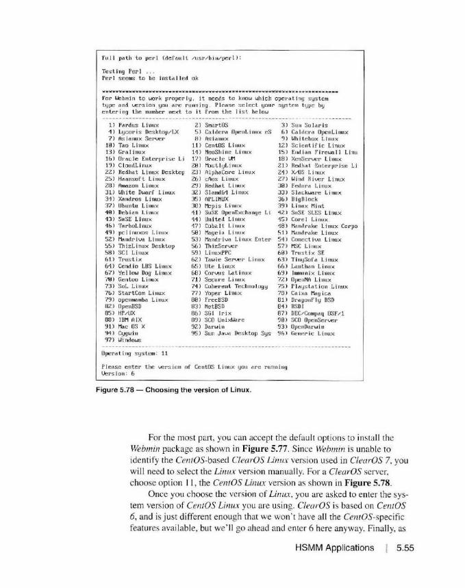
full path t o per I (def au I l / uSr / b i 11/per I ) :
Tes ling Per l .. . Per I seems to be i ns td I I ed ok
Jl(Hlll1MUlllMU llHJI H tu' ""' "'"' 111111M lltl4 M••• .... ..,MM .... l l--··----· ...... u ..... B .. ilt .. ) t-Hli tli 1'1 •1l OI MMMW.-W MK-
For Webmin to wor k proper ly , it needs t o know whi c h ope r a t ing s ys t em t ype and \JCrs i on you are runn i ng . Plea se s elec t your s ystem l lJpe by enleriny t he number next to i t from t he I i s l be low
1) rardus Li nux 2 ) SmartoS 3 ) Su 11 Su lari s 4 ) Lycori s Desktop/ LX Sl Ca. ldera Opelll i nux eS 6) Ca I rlf:ra OpenL i nux 7) As ianux Server 8) As ianux 9) Wh i l cbox L i nux
10) Tao Linux 11 ) Cen t OS Linux 12 ) Sc ienti fi c Linux 13) Gra l i nux 1<\) NeoSh ine Linux 15 ) End i an fi r ewa 11 Li nu 1& > Orocle Ent erpri se Li 17 ) Orac le U1 18 ) XenScr ver Linux 19 ) Cloudl inux Z0 l ttis t I yL i nu x Zll Redha l Enterpri se Li 22) Redhat Linux Desktop 23) AlphaCore Li nux 24) X/OS Linux 25) Haansof t Linux 26) cAos L inux 27) 28 ) Amazon Linux 29 ) Redhat Li nux 30) 3 1) Wh i t e Dwar f Linux 32) Slamd&4 Li nux 33) 31 ) X<>ndros Linux 35) APLI NUX 36) 37 ) Ubuntu Linux 30 ) Mep is Li nux 39 ) 10) Dc bi a n L i nu x 11 ) SuSE OpcnExchnnge Li 42) 43 ) SuSE L im1x 1 4 ) United Linu x 15 ) 4() ) TurboLlnux 17) Coba It Linux 48 ) 49) pc l i nuxos L inux 50 ) Mage i a L inu x 51l 52) Ma.ndriva Li nux 53 ) Mandr iv..' Linux Ent er 51 ) 55 ) Th i ~Linux Desklup 56 l Th izSer ver 57 ) 58) SC I Linux 59) Li nuxPPC 60) 61l Trus t ix 62 ) Ta wi e Ser\..ler Linux &3) &1l Cendl o LBS Linux 65) Ute Li11ux (,fl)
&7l Ye llow Dog Lim1x 68) Corvus Lat i nu x &9 l 70) Gentoo Linux '/1) Secure Linux 72) 73) SoL Linux 71 ) Coherent Technology 75 ) 7& J Star t Com Linux 77) Yoper Linux 78 ) 79 ) opc nmamba L i nux 80 l FreeBSD 81) 82 ) OpenBSD 63) Net BSD 84 ) 85 ) HP/UX 66) SGI l r i x 67) 88 l IBM AIX 89 ) SCO Uni xWare 90) '!1 ) Mo.c OS X 92) D4 rwin 93) 94) Cygwi n 95) Sun Java Desktop Sys 96) 'f l) Windows
Opcra t i ng sys tem: 11
Please e nt er the vers ion of CentOS Linux you are r unn ing Uers ion : 6
Figure 5.78 - Choosing the version of Linux.
Wi nd River L inux Fedora Li nux Slackware Li nux BigDlock Li nux Mint sus r. su:s Linux Cord Li nux Mnnt1 rake L i nux Corpo Mandrake Linux Concct i l,,..\l Linux MSC Linux Trus t ix SE TinySofa Linux Lanthi\n Linux lrrwru n i x Linux O)le 11NA l. i nux Pl ayst.a t ion Linux Cai xa t\\g ic<1 DrogonFly BSD BSDI DEC/ Comprtq OSF /l SCO OpcnSer ver 0~1c11D'3rwi n Gt: 11r:r ic: Linux
For the most part , you can accept the default options to install the Webmin package as shown in Figure 5.77. Since Webmin is unable to identify the Ce1110S-based ClearOS Linux vers io n used in ClearOS 7, you will need to select the Linux version manually. Fo r a ClearOS server, choose option 11 , the CentOS Linux version as shown in Figure 5.78.
Once you choose the version of Linux. you are asked to enter the system version of CentOS Linux you are using. ClearOS is based on CentOS 6, and is j ust different enough that we won' t have all the Ce1110S-specific features available , but we' ll go ahead and enter 6 here anyway. Finally. as
HSMM Applications 5.55

5.56
31) IJh i le Dwarf Linux 32) S I an>'.164 L inux 3~) S l ttckware Li nux 31) x.,,11dros Linux 35) APLI NUX JC,) DigHlock 37) llhu11tu Linux 38) Hepis Linux 39) Linux Mint 40) Deb iC\n Linux 41) SuSE OpP.nf.xchange Li 17. ) SuSE SLES Linux 13) Su St: Linux 14) United Linux 1S) Cor e l Linux 46) ·1\1 r ho!. i nux 47) Cob<1 lt Linux 10) Mandrake Linux Corpo 49) pclinuxos L inux 50) Mage ia Linux S I l Mandrake Linux 52) ~\11clri vt\ Linux ~3) Mandr iv.-1 Linux Enter· 51) Concctiva Linux 55) 111 i zLi nux Desktop ~) TilizSer ver 57) tt;C Li nux 58) SC I Li nux 59) L inuxPPC 60) Trus ti x SE 61) Trus l ix &ZJ Tttwie Seri...Jer Linux &3) Ti nySofa Linux Ml Cend io LBS Linux 65) Ute Linux &b l Lanthdn Li nux b7l Ye I low Dog Li nux (,8 ) Corw s l.<tlinux &9l l nm.tnix Linux 70) Gcnloo Linux 71) Secure L inux ni OpenNA Li nux 73) SoL Linux ·11) Coherent Technology 75) P laystation l.i nux 7&) Sl.01rlC:om Linux "??l Yoper Linux "?I)) C<dxa M..1gica 79) opcnfl"k.,mha Linux 00 ) free BSD 8 1) Dragonfly BSD 82) Opc nllSD 83 ) Ne t BSD 81) DSDI 85) IW/ UX 86) SG I I r i x 137 ) DEC/Compaq OSl"/1 88) IOH n IX 89) SCO Uni x\J.c1rc 90) SCO OpenServer 91) Mrtc us x 92 l Darwin ')J) 01lenDarwi n 91) Cygwin 'l';l Sun Jav.1 Desktop Sys 'l6) Generic Linux 9"1) Windows
OpcN li ny s y s tem: 11
Pleas e enter the version of Cen lOS Linux you are runn i ng Uers ion : (1
Opera t i nr1 system name: Cr.ntOS Linux OperA'l i n!J s ustem vers ion : 6
l-Jebm i n uses its own pnssword pr-otectcd ~b server to provide access to t he .J.dmini strat i on progrmns. Tile se tup scr ipt ne:eds to know :
- Wl1d l port to run the l..t!b server on. There rrust not be another Wl'b s erver a l reddy 11 s in!1 this por t.
- 111c l0<J in Hllme requi red to access thr. u:b server . - Tilc pnsst.XJrd required to dCCt:ss the web ser\Jf:r. - I f' Lile webserver shnn Id nse SSL ( if 9our s ystem s 111111orts i tl. - Wluo: l hr.:r to start lJebmi11 ut hoot t iroc.
Web s cr ... er port (def du It 101lll0): Loy i 11 nnrne (cle f uu l t acimi 11):
Login pclssword : PassU'lrti ttga in : The Per l SSLe,,y I ibrdry i s not ins lo ll e d. SSL not aua i lnb lc. StRrt IJchmin al boot t i n"' <wnl : y_
Figure 5.79 - Completing the Webmin install configuration.
Chapter 5
shown in Figure 5.79, you are asked to choose the web server port you will use to access Webmin, along with a log in name and password.
You will also see a not ification that the Perl SSLeay library is not installed and that SSL is not avai lable. Since we can ' t use SSL encryptio n on our A mateur Radio HSMM networks because o f the Pi.111 97 rules, this is perfect for an HSMM network. If you plan on using a ClearOS server outside of Amateur Radio, you may want to install the Perl SSL libraries to support secure access to Web111in. lt"s not hard to do, but this isn't what we need for our HSMM server so we won't wo1Ty about using SSL with Webmin.

M H Iii! 111111IIU1111 It H llHllHH ll MM MJl)j UHll II II II It I MH MMJllMllM llllll Ill MM IUI UH II MoM-M-Mlll!JIUHH HU 111111Ull 11 M JI MJI
Copyinrr files to / Us r /loca l /wcbmin .. . . done
Creating web server conf iy f i !es .. . . done
Creating a ccess contro I f i le .. . . done
Inserting path to per I into scripts .. . . done
Creating s tart and s top scr i pt.s .. . . done
Copying conf ig files .. . . done
Configuring Webmin to start at boot time .. . . done
Creating uninstall script /etc/webmin/ uninstal l . s h .. . . done
Changing owner s hip and permi ss ions .. done
Runn ing pos tinstal l scripts .. . . done
Enab l ing background status collect ion .. . . done
Attempting to start Webmin mini web server .. Starting Webmin server in / usr/local/webmin Pre - loaded WebminCore . . done
111111111111111111 M MMHH II( lflUlfHUll lfll II llll llll H 10111 lll Hlt M 111 llll lflllM MM ... -Jll...,.......,.111-JtH llll l lJI H UH Ull l!HJl 1111 fl M J1
Webmi n has been insta I led and star ted successfully. Use your web browser to go to
http ://K\.15GP-server. loca I .mesh : 10000/
and login with the name and password you entered previously.
Croot@K\.15GP-server webmin - 1. 7701"
Figure 5.80 - Completing the Webmin package installation.
Lastly, you are asked if you want lo stare Web111i11 at boot time. Again, the choice is up to you as you can always start the Webmin service from the ClearOS web management GUI, but I prefer to have Webmin start automatically when the server boots.
Webmin will then complete the installation and conliguration process as shown in Figure 5.80. When the installation is complete, you can log
HSMM Applications 5.57
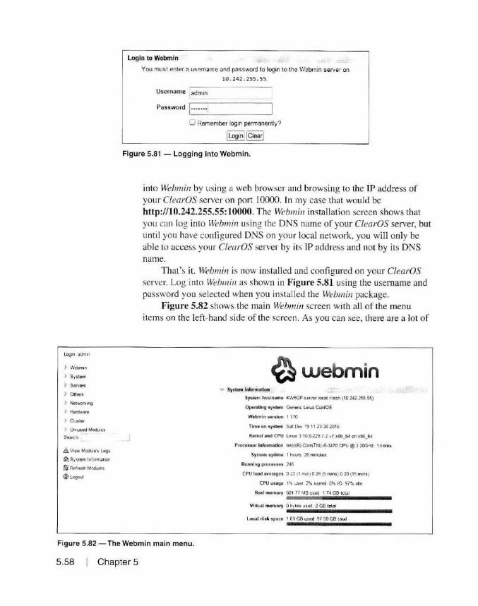
Login adrnin
~ Webnun
P System
~ 5.,..,. > Others
> Ne<wotk•ng
~ H•rt!w:w•
> Ouster
~ Un-used Mc:dules
Su.ch
4l. Voew Modules Logs
~System Information
~ Ref1e1h Modules
(§} Log<>J1
login to Webmin
You must enter a usernarne and password to login to the Webmin server on
10. 242 . 255. 55.
Username admin
Password ~I ·_··_··_··_I ___ ___ ~ 0 Remember login permanently?
I Login! I Clear!
Figure 5.81 - Logging into Webmin.
into Webmin by using a web browser and browsing to the IP address of your ClearOS server on port 10000. In my case that would be h ttp://10.242.255.55: 10000. The Web111i11 installation screen shows that you can log into Weh111 i11 using the DNS name of your ClearOS server, but un til you have configured DNS on your local network. you will only be able to access your ClearOS server by its IP address and not by its DNS name.
That's it. Web111i11 is now installed and configured on your ClearOS server. Log into Weh111i11 as shown in Figure 5.81 using the usemame and password you selected when you installed the Webmin package.
Figure 5.82 shows the main Webmin screen with all of the menu items on the left-hand s ide of the screen. As you can see, there are a lot of
~webmin v System Information
System hostname K\\ISGP-seNer loc4d m&Sh (10 242 255 55)
Opereting system Cene#1t Ltnux Ce<itOS
Webmin version 1 770
Time on sys1em Sa1 De<. 19 1113 30 2015
Kt mt l and CPU L.nux 3 10 0·229 1 2 v7 x06_6J on x06_64
Processo1 information lotcl(RJ Core{TM} 15-3470 CPU @ 3 200Hz 1 tores
System uptime 1 hours 26 mtnules
Running processes ]4G
CPU load averages 0 22 (1 min) 0 28 {S mins) O 20 (15 m1ns )
CPU usage 1% user 2% kernel 0% 10 97% idle
Reel memof) 601 7f MB used 1 74 GB lotal
VilluoJ memory 0 b~les used, 2 GB total
Local disk space 1 61 GB used 97.90 GB total
Figure 5.82 - The Webmin main menu.
5 .58 Chapter 5

Logm aO'i in ·.~\.1e1n:!e~ Filemin 1.'0C.1 i= ~~~·,;;u1;i~-:o ·
• ~ ... ebmS'I El Q. • • • 2 ;;:: (I )( !H'Hl l!J O .t.1. x i!. l.l ~ Sys1~ P~;H 1
~ """'"' - Action a .... °"""""' Pit_rmh'llOM L.nt Moddic• UOft rme
. ""'"" ~ .,, a :01s l!!"S :o ·~·: · ~ 11'i1Si 11
Comm'""""' CuslOll'l Comm.ancb
0 ii .... a H & ... .,... 0555 2015f12119·09 57,55
F1 ~ M~ l) • ... a 307 ~B 11orroot f]~~~ zo · ~.n:""ll 09 S7 2~
HH P TtMw'O! .J II .. a HB roouoot 0755 20 i5/121l9 11102)
J:r~ariW M:t1':19l" Por1 Modulos '-' w """"' a 6 0 't1'H •OOUOol or::.:. :•a:s:ov11 o<1~n1 P«lle<1ed Web 0.f!CIOOOI
Q SSH login ~ ·~ a ... '°"''°"' 0555 201!.f1211 D· Oil5'417
Sysll'r'll and $eNGI S1atvs L! JI. .... a !8 11) om :01S..- ]'1 9 ~95'' 22
Tt!• tlogiin Li ii ...... a ...... l'OOltOOI 015' 201'i08112 · ot1217 ._...,_......,
~ Netwc:rir.mg w • a ~tlf'l15 rootfOOi 0755 101~ll8'12 · 09UH
) ~<hv.ilre 0 ii ... a t b1•1 rcot·root OTS5 2'a1'5-l\W12 ·~'2227
t Oust« ii a J'.'. ' C-!d7 ' 2 u t.10< oe,1e' : 01!.· '11· w
• Un-u5.e<I Modt.kJ
S.onn u ii .... a H 8 roolJOCI °'"' 201S."12119-1t 2ll1
6 v,....,.&.&oou19·s Logs 0 ii a 1 ' 00,M 01 : :. 1o·s.1:_ · ~ ' ('IJl ! .:
.t:l. s,,tem l"'01TT1a1hon 0 ~ .... a lfU.B ........ ~SS :?Ol511211 1t - 1002 l l
t'1 R.i4re3t'I M~a .J a & ~.It', r~: rcor NS ~ i o·;.-c~;1 2 .~;:- ~·
®'"'""' .J ii a &1>,-Wt root.root 0155 21J~s.<!9m·2Jo129
" ii '" a '1 011u roouooi 05S'J io1 sn:>11~ OJ<;.7 •)
(; ii ..... a H8 root root 1777 201s11zng. 11 ia 56
·~ ii a ... l~lf,)O( ans 20: '5.: · :i~i· O'i 5)01
u a ... root·root "" 2015112"9 · I I _ t6 48
Cl );: :11Aoreabel a::-, JOtli1 ratlJ'?Ot "'" ~01 ~· 2119 00~72)
Figure 5.83 -The Webmin fi le manager.
things you can do with Webmin. Some options may not be available since we installed Weh111in using the generic Ce1110S Linux option. but the main thing I use Webmin for is the File Manager listed under the OTHERS menu as shown in Figure 5.83.
Using the Weh111in Fi le Manager, you can eas ily upload, download, and edit fi les on your Linux server w ith just about the same look and fee l of the Windows Fi le Manager. This is a quick and easy way to upload ti les such as web server pages to your CfearOS server without having to install the FTP server application and configuring it to use your web server home folder as the default FTP destination. The Weh111i11 Fi le Manager is also a great tool to use to edit configuration fi les and o ther text files since it has a nice visual text edi tor instead of having to use a c:ommand line edi tor such as vi or 11a110. Anyone that has used a command line text editor will te ll you that having a web-based text editor sure makes things a who le lot easie r for someone new to Linux.
Installing ClearOS Applications It may seem like it took forever, but we' re finally at the reason we did
all this - to install the applications we can use on our HSMM networks.
HSMM Applications 5.59

We're at the point where we can finally put a ll the pieces together. From here on out, you·11 be amazed at just how simple and easy it is to install and configure a bunch of Internet applications on a ClearOS server. If you·ve ever done th is with a Wi11dm1 ·s server or another Linux distribution, you will appreciate the simplic ity. So. without any further ado, let 's get into installing those applications.
ClearOS applications are installed using the ClearOS Marketplace. As I mentioned earlier. don' t le t the word "Marketplace" scare you. This is just the place where you go to get the applications. While some ClearOS server applications are not free. the vast majority are indeed free and can be install ed with just a few mouse c licks.
To access the C!earOS Marketplace, select the MARKETPLACE menu from either the top or left-hand side menu options. Next, you will see the screen shown in Figure 5.84. From here, you can scroll through all of the avai !able applicat ions or you can select filters to show you only specific types of applications, such as only the free ones. For our first application,
Community Clea-OS Marketplace 7 ~ 0 Ill
Q
~ Oovd
~ N otwo rk
't ,~ ..
• (learOS 1'-'lar..et;>la;:.e •!twf 1 .. re y<X. Ca.J'l add rt.Pw aops .:i.nd~H to your sy'item Apps available 1n t.~ Mar'cetp tace have gooe ~ .. ·c~:;n a <ot• n;o;?nt Qu-.·11; con:roi p!'OC• 5S :o ' "isu1• the- qu a 1ty and St'<unty of each subm1ss:ion
:.- , =-i:i'
f§#ifj§@f a Select AU Reset Filtot1
'I
1:1 ·:. • . .:.- ~1r • : . 1 · ..1..:: .. ·n · • i:· ·-'I"~
.;:::.::·.:s:. · )!.-,·.' , toe"•·.:..."""lr:>the " •ti...,.\ I.,· :c~.f,91 <t'C.,. .. ··p . .J' "'" :>.a:=-::·~;*-S ~F( ·j!S,
~c.,..:11 • ··~··"'; 1 ..... ., &.:;.::1~ues '"n -s l".:.1v1•
·~.::J..·es~~~J · t111 .:. ·1=.t.:::::r~;s,e;fc-ir"·'
~.-. ~-, , .. -~ e~. '°'" "',tJ.' ~.: L t..Q f\S i."·i::l l?• l~,,~ : •1; ~ '
:-~ . ~,;>r :-: . .,, .• <"",. ''"'~: ..i .:. ... ~ l.l• r-t:ase.:: 'o•"V•"';
• • ...,, •••••
~ f!o"!
•••
- U'f'laying \ ·21lof126 -
•·••fot"' b L I• moo:t of 1,..;ers to me \y:U~ I.A fig ::·.- .r.c-::ount lr'pYt a::>o 1-rpofl 1errpl111e ~ ... pporn (:yrlT\,'l~rateO va ves tCVS) th.at can be
(fNteo fror .. Ml}· sp11!l'~t ~.c.alH)n
1 ·Jp0:.-..vff::~ E"c~et..: "
:..."A<H->s Cor u OI: L st (ACL' ai•ow1"9 an
Acn- n ~-J'a.10!" froot) toq.m: ~ .. b·.tc::!fr•n ~uator
an•<>~ to ~·fc -;or.i -;vat on P~l>S ..,. th n .... "etxon1't9 o n a peJ" 1..s.!'r bas.1
Figure 5.84 - The ClearOS Marketplace.
5.60 Chapter 5

Q
~Cloud
li'.J Network
~ System Accounts
Account ManagEr
Backup
Cle MOS
Dashboard
Si.: po on
~ Reports
• DASHBOARD 0 f, fAr<r<F lPl ACc ~ SUPPORl ;'< ROOT
ClearOS Marketplace is where you can add new apps and services to your system. Apps available in the Marketplace have gone through a stringent quali ty control process to ensure the qual ity and security of each submission.
AnyCateg • Any Price lnuoaucE-C
Install Selected ~ps Select All Reset Fiiters
Direc tory Server
*** ~rec
DMZ
The d1rectory server·~ an
1mp ienentat10,, {us1no
OpenLDAP) cf Inf' l u,1hh\..-1gnt
Directory Ae<ess Pro,ocol I hc>
duectcrycontc.ins iri:v• ·~ 1.1trur1 o·~
user re<oros. t.'Ji-io~ . :e· ~ acc'?ss
1;9::!,f!,1 Learn More
Any Statvs ~ II .. Displaying21-40of126 ..
**** =~c-e
f j@f@§b!H Learn More
INSrALLEO
DNSSe•ve1
Figure 5.85 - Selecting the Directory Server application for installation.
we' ll install the Web Server. At this point. you can instal l any application you desire to run on your HSMM network, but we' II start with a bas ic set until you get the hang of th ings.
Page and scroll through the ClearOS Marketplace applications list until you see the Directory Server and Web Server applications as shown in Figures 5.85 and 5.86. We'll need both to set up the Web Server and other applications that interact with the User accounts . Select them for installation and then go back to the top of the page and select INSTALL SE
LECTED APPS. You can install entire groups of applications at once, but to keep things simple, we'll insta ll the applications one at a time.
On the next screen, shown in Figure 5.87, simply select the DOWN
LOAD AND INSTALL option. Your ClearOS server wi ll then download and install the Directory Server and Web Server applicat ions from the ClearOS Marketplace. When the installation is complete, it 's time to configure your Web Server. From the left-hand menu, select the WEB SERVER option that is found under the SERVER menu. The first ti me you install an application that may require the configuration of ocher features on the ClearOS server.
HSMM Applications 5.61

• JASH30A.RD ~ SU" PORT ~ ROOT
·····-·-·-··-···-·-··-·-·-··------------~-- ----~-------
·OCl ·-"'*"'
0 0
'~" .... o'!..''/.o
*****
"'"'*
"he ~""' c. ''O', ·"-=-c, :-as.:-c .,-.;.r.ag~x>r: fraMe•1. 0f~
·~, ;,· r r ·p, -:.:>\ ,. \ .:.rs;. ;"I a· ·~:;~ t ·.e .. ~-£>' 'lt~r".i; .;
::· ~· · :-:.:..~ :::-. .,-. =~,-= ·: ~., :: 3~-::-::ar: .. l" :e;·c.t~ ~-.: f· .... 11.:., .--,-:.:::'\ IS·.-·1 .. : ri ~:i.:..? a~ ,:: .... -._,,:;..
mlll l emr1f\.1o1c
;, -,·. "~ r: ·• . -•~:~ .i' ,.;r · :,,,· r"<:" J d ' 7 ~ ... • ,-:,. • _,,. ,·.e::> 1"?;1v ·. t ·x ~ ·1,1t "J f,. ~,·r :."'-e ~o ,:al A-.::-a 1 .~t:. o: ~
1n·pleTPe; 1'•] o :..': ::, ~: ~er. ~r s opt ona.r, i10.-~.;--..,.1 .
se,,,::r ,'l.l oe·n8f ts Jr.: ?2 ne~ ~1/'1 a'., ,,,rrP ,'l'> ·l•J pa'~l'i°
~c• .:.<.s : W t':'. t.<,•·1q.:a~r1r-;11 •::ecreJ.o;m·J
t-ar· :-.-.-. ::t" _i~.:> "'.<Jg!"~ ,·,et:; :'O' ''5' ts b1 .1., ... ,
H#l§MH Learn"~•
- i-..,. .,.,, 1·,·-~1 ... ,, "ie : 11 ·~·h_ rs= aoc1: 1· -:,~ ai-;. s ..:. -.1[;1 :. - aq
..:ir.,;r· .;.:: .H.::-2 :;_ t 2 :/ s;;.r . -.::e s r '"',:;~ ~ 1-.w.s • ri a·l'::
~ - ::~· • ' •• --~ : ·· ·:. ".:::::: : •-: =i"::: ~·· -:. ~'?-,'?·
sso )' f
/, d ;._.-.· .1,.·1
El
SSO · vr
-hi- 'Neb Proxy Al.to-Discover')· Protocol is a
rT"ethod us~ zy_,· d · ei~ c o?v ::-es on the rn::two<t.. tc
IO(O.lt? av~t. of,;. cc r.f1-;uat on f.1eusing DHCP
ar.u or DNS c s.c.o·:~ry n· ethocs O'l.:e ce-tecr on
a11c c?-.'<n-oa.c c f \J",E ~0·1 f <;l. ' at·ori f ile are
canipj€t,:. : !:M ~ exi?CLJtee'. tooe-t1~1m.n.; th~
f j§fij§M!f Learn ~re
iti~ weo s.er~·er .=.;:;o o rov·ces an 'lstance of the
A pacl1~ !i.erver aJor.g with bas.c tasks for creating
new wet>s~te ass-:ts. il'\€: Apache webservt>f !:. tt1e
wo rld'> most popular 'Neb server. no Coubt as a
resl.Jll oi .ts tra.ck re::ord for sec w ty . features.
scalab•l- ty ari c st.?.b.l t).
Im LeamMcY.e
! -, .
Z.tiafa ( o rrn"'lt. 'l ry :s arc o pen-Sot.rce . fl .. !1-f~ature-a'
-ra I s:orag.;:> a.no ~r:jupw.a.re so! i.. t en Z.irafa.
-'lCI JC-:-S a ·ueo-bas~c r,cer!ace for p erforri-ng
n·.a I acor.:-u boor ar,(l .;: alenc ar h .. nct10<"s T'to;
,-o·,·m .. n t) : -: :. Jeri. ::ar s...pnc,.-: d.r)' ... i...n·~r ? ;
1~·, '' a the v.eb·ba.sed r,tertace or thro1..i;:h a.
fi§ii@@ii Lec,n More
Figure 5.86 - Selecting the Web Server application for installation.
5.62 Chapter 5
you will be asked to configure those as well. In the case of the Web Server, we also need to configure the ClearOS Account Manager so that we can set up the user permissions for anyone administering the web server as shown in F igure 5.88. A ll you need to do is select CONFIGURE BUILT-IN DI
RECTORY for the OpenLDAP application and the ClearOS server will automat ically take care of everything needed to configure the OpenLDAP Directory Server and the CleurOS Account Manager.
Next, you will see the Directory Server configuration screen. You will need to enter the domain of your ClearOS server and then initi alize the Directory Server as shown in Figure 5.89. Once the Di rectory Server is in itialized . you will see the screen shown in Figure 5.90.
Now let 's go back to the Web Server screen and finish the eonfigura-
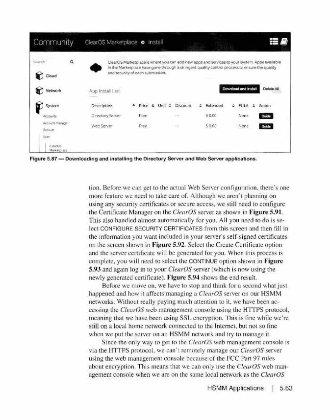
l('.J Cloud
~Network
fl System
Ac::co1.mts
ACCO.Jn! Manager
Back.up
s.,., C1eatOS Market lace
0. • ClearOS Marketplace 1s where you can add new apps and services to yo ur system. Apps available in the Marketplace have gone through a stnngent quality control process to ensure the quality and security of each submission.
l\pp lnsiall List Download and lns1all Delete All
Description • Price ; Unit :: Discount Extended ; EULA ; Action
Directory Server f'ree SO OD None -Web Server Free S0.00 None -Figure 5.87 - Downloading and installing the Directory Server and Web Server applications.
tion. Before we can get to the actual Web Server configurat ion. there 's one more feature we need to take care o r. Although we aren ' t planning on using any security certi ficates or secure access, we still need to config ure the Certificate Manager o n the ClearOS server as shown in Figure 5.91. This also handled almost automaticall y for you. A ll you need to do is select CONFIGURE SECURITY CE RTIFICATES from this screen and then fill in the information you want included in your server's self-signed certificates o n the screen show n in Figure 5.92. Select the Create Certificate option and the server ce11ificate will be generated for you. When this process is comple te, you will need to select the CONTINUE option shown in Figure 5.93 and again log in to your ClearOS server (which is now using the newly generated certificate). Figure 5.94 shows the end resul t.
Before we move on, we have to stop and think for a second what j ust happened and how it affects managing a ClearOS server o n our HSMM networks. Without really paying much attention to it, we have been accessing the ClearOS web management console using the HTTPS protocol, meaning that we have been using SSL encryption. This is fine while we' re still on a local ho me network connected to the In ternet, but not so fine when we put the server on an HSMM network and try to manage it.
Since the o nly way to get to the ClearOS web management console is via the HTTPS protocol, we can ' t remotely manage our ClearOS server using the web management console because of the FCC Pa11 97 rules about encryption. This means that we can only use the ClearOS web management console when we are on the same local ne twork as the ClearOS
HSMM Applications 5 .63
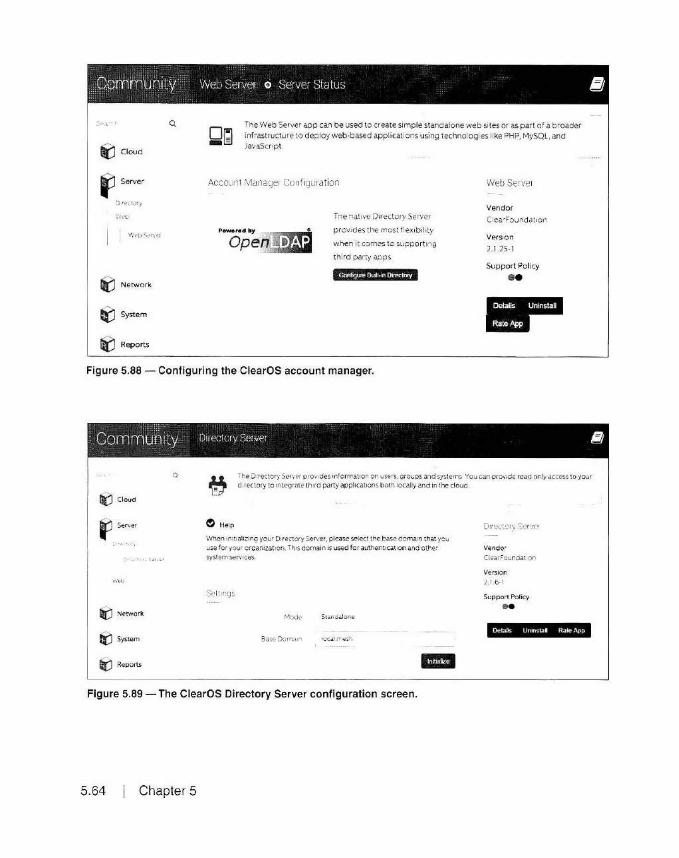
Community Web Server o Serw~r S'tatus lflJ
Q
i) Cloud
~ Server
D r~ct O')
',\.-L
I \11.'f'bS.,.".f-r
iJ Network
~ System
Ii() Reports
Dr:i -[3
The Web Server app can be used to create simple 5;tandalone web sites or as part of a broader infrastructure to deploy web-based applications using technologies like PHP, MySQL, and JavaScript.
Accoufl\ Manage1 Conf1gurat1on
P~r•dby
Open.~_..._
Tne native Directory Server
provides the most flex ibi li ty
when it comes to supporting
third party apps
Configure Blllll-in 01rectmy
Web Server
Vendor
Ctea' Foundat1on
Version
2.1-25-1
Support Policy
••
Figure 5.88 - Configuring the ClearOS account manager.
Community Duectury Server l!J
Q
ri:i Cloud
f Server
:- -.- ·
w".'eb
i:J Network
li'J System
Ii() Reports
The Directory Server p1ov1des information on users, croups and systems Yo:..i can provode read only access to your
d .rect.o ry to 1ntegr.:1te 1h1rd party applications both locally and in the cloud.
~ Help
When 1mt1alizinQ your Directory Server, plec.se sele<t the bcise dornam that you
use for your or-r~ arnzation. This domain 1s used for authenucauon and other
system services.
Mode Standalone
5ase Dorr.a1., -
D• ~6.:~::iry Servi:ir
Vendor
ClearFownoat1on
Version
2.1 6 I
Support Pol icy
•• Oetaik U nin'ilRD Rale App
Figure 5.89 - The ClearOS Directory Server configuration screen.
5.64 Chapter 5

i) Cloud
Settings
:i ·~c-..Y,
Tr.e Dir~-:.:ory Serve.r pro .. de~ 1n'orm at on on r.J~er:j,, croup~ -.:.nd systems You C!n p inte-grate third party applica::iom bo:h locally and n :he :.lovd
Standatore f Serve•
I :.··~~ .... !. ..... ., aa~eOoma n
II li'.'.J Network
Polic1e~
~Reports
II
Director/ lnformat10i1
Capab1l1Ut$
Connection Information
Base ON dC•IOCal.d<•~Sh
S n c Df.I cri•rnanl.ger1ou•lntemal,dc2local.dc=~
Figure 5.90 - The ClearOS Directory Manager is now configured and ready for use.
server. In other words, you have to be physically a t the node hosting the ClearOS server to use the ClearOS web management conso le. This is yet another reason to have a basic method to remotely manage some of the components on ClearOS. For example, using Wehmi11, you can configure and control a lot of the basic functions of your ClearOS server without having to use the encrypted ClearOS web management GUI. This is something you need to consider if you're going to have your server in a remote location.
Another way you can work around the encrypted management console issue is to provide for some other method of access. such as a public Internet
HSMM Applications 5 .65
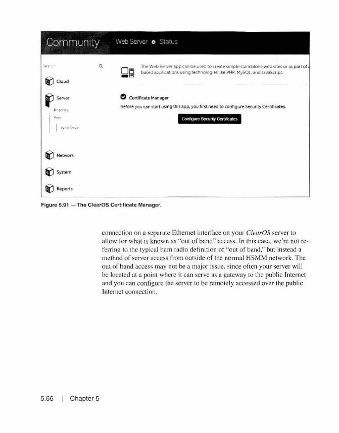
.:;~; · .. Q
01!1 The Web Server app can be used to create simple standalone web sites or as part or based appl1cat1ons using technologies like PHP, MySQL, and JavaScript.
iJ Cloud - IS
~ Certificate Manager
Before you can start using this app, you fi rst need to configure Security Cert ificates.
C.onl19ure Security CerllfJCates
Ii() Network
ti:J System
~ Reports
Figure 5.91 - The ClearOS Certificate Manager.
5.66 Chapter 5
connection on a separalc Ethernet inte1face on your C/earOS server to allow for what is known as "out of band" access. In this case, we're not referring to the typical ham radio definition of "out of band," but instead a method of server access from outside of the nonnal HSMM network. The out of band access may not be a major issue, since often your server will be located at a poi nt where it can serve as a gateway to the public Internet and you can configure the server to be remotely accessed over the public Internet connection.

clearOS
Sea1cr Q
~ Cloud
~ Server
lli'.J Network
~System Accounts
Account Manager
6aickup
Sa~
C ertlf1ca.te Mana.oer
Date and Time
General Settlng::.
System Reo1strat1o n
• DASHBOARD 0 MARKETPLACE ~ SUPPO
Security certificates are an industry standard for encrypt ing information sent over a enabling digital signatures. The Certificate Manager app provides the ability to ere to users and apps.
Certificate Authority
Certificate Type Certificate Authority
Internet Hostname KWSGP-server local mesh
Organization OBARC
Unit KWSGP
City Southaven
State, Province or Region MS
Country United States ·I
'*''''' Figure 5.92 - Configuring the ClearOS Certificate Authority.
HSMM Applications 5.67

5.68
A Warning
-"' The web interface rs restarting with the new security certificates.
~ Security Certificates
This web interface automatically restarts after your new security certificates are created. You will see a warning in your web browser similar to the screenshot below. All is well, and you can proceed safely.
1§1!.ll!M
Web Browser Warning
This Connection is Untrusted -~----------~
Yo-.r rui .. e uho f ~fc11; :o CQMotC.'l MCl.lt•ty to 192 . l H .SS ,, :UOl. C>'w1 w~ u.n't :onf1rM tt.a1 y~r ttnr«tJC.n cs s.taa•
Norna lty. Nr.en yo .. 'U'J to connKt ~1..re-ty . s.r..tt wll J)l"9Wn1 t:nJSted deNdotx:ln to prcwe- tt.Jt you u.a QOlf'9 to the nght ~. Hc.wt..,t r. tt-.cs Sttt's deNky un'l be .,mf@d.
What Should I Do?
It you usuily cont.ea :o this i,U 1¥ 1tt'iout proolem.s, thlS e.rrorcouid mHn tf\Jt ~mofOM rs. ~-Yll"'9 to mpersor~t• the sr.t. and you shouldn't co~.
Technical Details
I U ndentand the RI 1kll
Figure 5.93 - Completing the ClearOS Certificate Manager configuration.
Chapter 5

Search Q
i'.J Cloud
~ Seiver
11('.l Network
f1 System
Accoun~
Account ManaQer
Sack up
Ceruf1cate Manager
Edition Manager
MA.II Settings
Security certificates are an industry standard for encrypting information sent over enabling d1g1tal signatures. The Ceruficate Manager app provides the ability to er to users and apps.
Certificates
Descr ip tion
Certificate Authority
Default Cert1f1cate
External Cenif1cates
Certificate
No data available in table
• Certificate
ca·cert.pem
sys·O·cert.pem
• Files
: Action
: Action
.. .. II
Figure 5.94 - The completed ClearOS Certificate Manager configuration.
HSMM Applicat ions 5.69
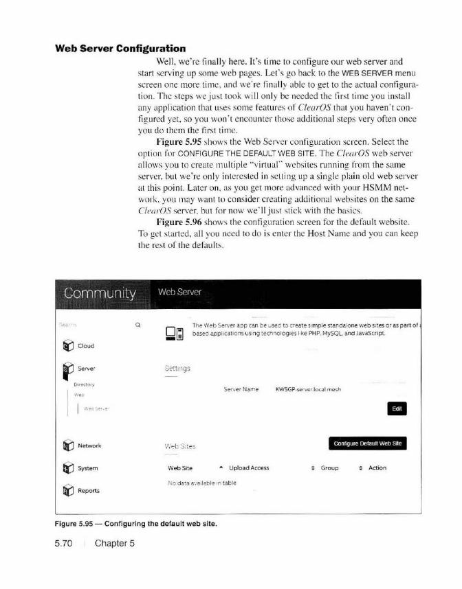
Web Server Configuration Well, we're linally here. Il's lime to configure our web server and
start serving up some web pages. Let's go back to the WEB SERVER menu screen one more time, and we' re fi nally able to ge t to the ac tual configuration. The steps we j ust took will o nly be needed the li rst time yo u install any application that uses some features o f ClearOS that yo u haven ' t confi g ured yet. so you won ' t encounter those additio nal steps very often once you do them the first time.
Figure 5.95 shows the Web Server con rig urat ion screen. Select the option for CONFIGURE THE DEFAULT WEB SITE. The ClearOS web server allows you to create mu lt iple ·'virt ual" websites running fro m the same server, but we're only interes ted in selli ng up a sing le plain old web server at this po int. Later o n. as yo u get more advanced with your HSMM network. you may want to consider c reating additional websi tes o n the same ClearOS server. but fo r now we' ll just stick with the basics.
Figure 5.96 shows the config uration screen for the default website. To get started , a ll you need lo do is enter the Host Name and you can keep the rest of the defau lts.
Community web Server
~Cloud
fJ Server
Dme~to1y
Neo
lii'.J Network
liJ System
~ Reports
Q
Dr:i -El
The Web Server app can be used to create simple standalone web sites or as part o f based appl1Cations using technologies bke PHP, MySQL, and JavaScript.
Sett ings
Server Name KWSGP-serverJocal.mesh
II
Wei~ Snes configure Default Web Site
Web Site • Upload Access ~ Group ~ Action
No data available in table
Figure 5.95 - Configuring the default web site.
5. 70 Chapter 5

Q
liJ Cloud
fl ,.,,,., J " t-C:V<'\'
li{j Network
1(1 5ystem
l[j Reports
Th~ W!!b <::~erve 1 aci; <:an b e 1.1r,ed t~ >::Tt:3t>t s-mcle ~:<!!.nCa!onci '"· ~ '=' s : es o· co; pan c f
be:;:e.j appl1 ( .!: or~ 1J~1n9 : ec-,.,r:-oivg :e '.; Me e ~HP, M1·SOL a:-d .'.a :~S~r :::~
Settings
WebSrte
Upload Access
Group
Options
55L Ccn f Cdte
:rab e CG
m Cancet
Figure 5.96 - The default web site configuration screen.
Figure 5.97 shows the ful ly configured web server screen. You can go back at any time and edit the settings and preferences for your web server. Now you can browse to the web server using the IP address of the ClearOS box and you should see the screen shown in Figure 5.98. At this po int, you can upload your web pages to the web server using Webmin, and if you installed and configured the FTP server. you can also upload your web pages using FTP. The ClearOS server file location to upload your web pages is at /var/www/html as shown in Figure 5.99.
That 's it. That's all there is to using C/earOS to set up a web server on your HSMM network. This is one reason that I like using the C/earOS
HSMM Applications 5.71

Corr1rnunity web server
o~ -El
::.<:>a·:. The Web Server app can be used to create simple standalone web sites or as part of based appl1cat1ons using technologies like PHP, MySQL. and JavaScript.
rtJ Cloud
~ Server Settings
01·cctory
I Server Natne KW5GP-serverJocal.mesh
\-.·ec.
I W~bS~rvC-f
i) Network Web Sites
e(j System Web Site • Upload Access
'1iJ Reports
kw 5gp·web · Default
Figure 5.97 - The completed web site configuration screen.
5.72
clear"c Con9ratulat1ons. your web server •S running1 You can fmd additional 1nfo rmallon 1n the ClearOS Web Server User GL11de Thank you for choosing ClearOS, the Hybrid Small Business Server Solut1on for today's 'jlfl311 m"ld d lStrlbtJIP.d organt7<"tlOflS
Figure 5.98 -The ClearOS default web page.
Chapter 5
: Group
all users
.. II
: Action

Logm actmrn Module lnde1t
f Wobm1n ~I 11¥ f \Y'MN J html f
• System Paqcs 1
• Servers N.,,,.
"' Others Ll r dex html
Command Shell u ' logo_png
Custom Commands
F~e Manager
Filemin
Actions Sta Own•r Uwr
a~ & 55 kB rOOI 1oet
a 19 54 kB rooc root
Permissions LHt Modiflcatktn Tame
201S.1()1.t . 09 22 5~
2015112i19 - 11 30 30
Figure 5.99 - Using Webmin to upload your web pages.
Li11ux distribution. Once you get everything installed. actually configuring and using the va1ious applicat ions is quick and easy. Now, let's set up some o ther applications on our CfearOS server.
SMTP E-Mail Server Another Internet-style application you may want to run on your
HSMM network is an e-mail server. ClearOS includes a Simple Mail Transfer Protocol (SMTP) server. along with Post Office Protocol 3 (POP3) and In ternet Message Access Protocol (IMAP) client support, meaning that you can use a standard e-mail c lient such as Microsoft Outlook to retrieve your e-mail. You can even link your e-mail server to the Internet to transfer e-mail between your HSMM network and Internet email systems.
As with the web server, se tting up an e-mail system on your ClearOS system is quick and easy. All you have to do is go to the ClearOS Marketplace and download the SMTP Server and IMAP and POP Server app li cations. To confi gure the SMTP server, enter the mai l domain and the mail server hostname for your server as shown in Figure 5.100. You can take the defaul t sett ings for the rest of your mail server configuration. That's all there is to it - your SMTP mail server is up and running.
To retrieve e-mail , you need to configure the ClearOS POP and IMAP server as shown in Figure 5.101. You will want to disable thesecure POP and IMAP settings and enable the s1a11dard POP and IMAP settings (the ones that don' t include secure in the label) to remain compliant with the Part 97 rules regard ing encryption.
Now, all you have to do is add the users to your ClearOS e-mail system as shown in Figure 5.102 and you 're ready to go. On the user side of things, all they have to do is configure the ir workstation e-mail client such as M icrosoft Outlook to use the IP address of the ClearOS e-mail server (or its DNS name if you have DNS running on your HSMM network). That's all there is to it - now you have added e-mail capabili ty to your HSMM network.
HSMM Applications 5. 73

l(J Clcud
f '"'""
I 1 ...
•
' • ; J L- . • •:' . -~· -1 • Port
Figure 5.100- Configuring the ClearOS SMTP e-mail server.
5.74 Chapter 5
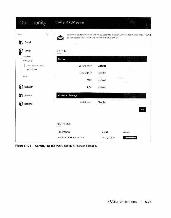
C 0 mm LJ n j ty I M/1 1-1 a·-icJ PUP Server
Search Q
~ Cloud
~ Server
Dir~tory
Messag•ng
!MAP and POP Server
SMTP Server
\Net;.
'° Network
I() System
iJ Reports
The IMAP and PO P server provides a stand ard set of services for mail cl ients (Thund to connect to the server and ret rieve/ display email
Settings
Secure IMAP Disab led
Secure POP Disabled
IMAP Enabled
POP Enabled
Advanced Settings
Push E-mail Disabled
App Policies
Policy Name Group Action
IMAP and POP Server User 1map_plug1n
Figure 5.101 - Configuring the POP3 and IMAP server settings.
HSMM Applications 5.75

Community Users o User Manager
Scar (r
~Cloud
Ii'.) Server
ti(! Network
1,'::m 1.,,·c...JpS
I ,_,..,
liCJ Reports
Q The user s app allows en c.d"'1 1r., s:ra"tor :o create, delete ~d mod fy users on the sysr
lo Ser d rectory wil aucomat 1ca11y d·s~~ay 8Pt1ors ai1a 1:abl-e ~oa us.er account.
User
Username
: rs: Name Glen
Las: Name
Password
Pc.ssword
App Policies
IMAP ard POP Server User Enabled ,.
SMTP Ser .•er User Enab,ed ,.
Al ases
• Cancel
Figure 5.102 - Adding users to your e-mail system.
5.76 Chapter 5

File Transfer Protocol (FTP) Server We're rolling out the applications fast and furious now. Again, you
can see why I like the ClearOS Linux distribution. Once you get past the initial installation, adding new applications usually just involves installing the application from the ClearOS Marketplace and just a few quick entries to complete the configuration.
Now, let's set up an FfP server so you can upload and download tiles over your HSMM network. Here is where the ClearOS version of an FfP server differs fro m a regular Ff P server. ClearOS has the ability to run the Flexshares application, which allows you to create shared folders on your ClearOS serve r. These folders can be accessed over your HSMM network similar to the shared folders on a Windows server, as well as by a web browser or FfP client such as FileZilla. While F/exshares may be an application you might like to have on your HSMM network, space just does not allow me to include it in a discussion of bas ic HSMM applications.
There's another applicatio n known as C/ipBucket that I prefer over F/exshares and the media server applications in ClearOS. We ' ll talk more about C/ipBucket in just a bit. The important thing to note is that the standard Ff P port 2 1 is reserved for the Flexshares application and cannot be
Community r-ri ::cN.?r
iCJ Ooud
I '1'
: : ."'!'' -~'
Me~·..JIQ• ~ t;·
weo
Q ~ The FTP S<>cvec provod es file management and >tOC.lQO u~ng t he standard FTP and F
Serve r N ame FTP
M.a x1mum Jn stance'S SO
Home Sh,vePort 2121
Ftexshar'll' Port 2 1
li'.J Netwmk •
e(J System
:\pp ::io.1CK'S
Pollc.y Name Group Action
FTP Server User ftp_plugin Hii. !¥ _11 ,_fi
Figure 5.103 - Configuring the ClearOS FTP server.
HSMM Applications 5.77

fie ldC Y- j 11Mfet S-11 lootmub tidP tt-vft'~ IVJil.ible!
_t · I~-' .~~tc: ~ ;' n ~¢ ·······
5-A,_(, • "r .;·1:lc :.!a.:;-. .. ., .- . -'""11'"•JS:-.AA•"'CG!Gt~C"<.....,. .7 ..-_..""!...
:.•."•'9"1. .... ~llt o.eniw, bOn; MUSSf.J
I ,.,~ 011'..,IW"'I\
·.l!.i Co""""'et . c. " • i.,... Ci! ~0•1• )
• JJ I ''-"'1 (~1,m ltew.tdl ..... .. + '7.'" N (\\fUS.1Un""'\"1bl di 1kl l
, yo W· (\llO.J41lS~lO\P11lil 1tJ
.....,~ ;5-).,.~~ Pn"r~I
._, G:
'-'H,(0 1t• J
~f4 (\INA~\1dm.-.\u1bl d1\t'JI
'-t" W (\ lfl )4'1\\ ."0'>P11bl.c. J
f11t::sc.e f!ldyp'
lculO.•I
Loe:"' Dl~l ([}jm(
toul[)KI
loulDlll·
l(.'(tlOu~
flrl""'()fl 0"'·"
_ _ _ · lleMt.t•lle! fY•,.,,_/Nft
1 111dirm11
j UJl·btn
• Cl ... ••r'IWI
' "
.... lln1l>1•e qroup,1111
~ >Mo.ntml
... loyo,~•HJ
~- ~ lUn. lotM s.i1a: ~,8Dllb-(IH
'"''" C.idyp< Wtfl'\Odd~ Pom1u1o ri1
11 Ten ~u ... llfl~/20H4:L 1dlr (06«)
g .rn~ FutiO'llHI ... l0f l 4/ 1015 !>:1 .. tdfrwll)564)
"'"" PNGirm~r l l1H / Xl1Stl:. tdfrw j0664)
w"
J ,• Qyeua:~ ••
Figure 5.104 -The FileZilla FTP client.
5.78 Chapter 5
easily changed. Therefore, the default ClearOS Ff P server is configured to run on port 2121 instead of the usual po1t 21 as shown in Figure 5.103.
To access the FfP server, you will need an Ff P client on your workstat ion such as the free open source FileZilla FfP client. Enter the IP address of your server in the Host field, a valid user name and password, and port 2 121. Select QUICKCONNECT and FileZilla should log you into the FTP server as shown in F igure 5.104.
On the left side of the screen you will see the fi les on your local computer and on the rig ht side you see the FfP folder on the ClearOS server. By default, you can only access your user 's home folder on the Clec1rOS server to upload files. To change this, you will need to modify the FfP configuration file (/etc/proftpd.conf) to select the desired FfP upload directory. The FfP file directory will then be common to all users. To trans-
fer files with FiieZilla, all you need to do is drag and drop the files from one side of the screen to the other, or right click on your mouse and select upload or download depending on the direction of the file transfer.
And there you have it, you now have an FTP file server running on your HSMM network where users can upload and share files with each other. ClearOS also includes the Plex and Serviio media server applications, which are designed to provide streaming media services directly to a device such as a network-capable TV. Again, these applications may be something you would want on your HSMM network, but space doesn't permit a more complete discussion of these applications.
Network Services Before we finish up with the C/earOS server and all of the user appli
cations it offers for HSMM networks, let's back up for a minute and discuss some of the Internet service applications available on ClearOS, such as Dynamic Host Configuration Protocol (DHCP), Domain Name Service (DNS), and Network Time Protocol (NTP).
Dynamic Host Configuration Protocol (DHCP) Dynamic Host Configuration Protocol, also known as DHCP, is used
to provide IP addresses and network configuration information to network clients such as workstations and other network devices. All of the Amateur Radio HSMM implementations provide an integrated DHCP server, but there may be cases where you want to set up your own. C/earOS has a DHCP server application you can use to provide basic DHCP server functionality. However. if you ' re going to provide DHCP to multiple IP subnets as would be the case if you implemented VLANS, you will need a DHCP server capable of providing IP addresses for multiple IP ranges and subnets. This would also involve the use of DHCP Relay commands on the routers or switches acting as the default gateway device for those subnets. While this can be done with the ClearOS server, it would involve manually editing the DHCP configuration file and cannot be managed using the C/earOS web management console.
Jn reality, when working with multiple DHCP subnets being served from one DHCP server, T prefer to do th is with a Windo ws server since it has a more full-featured implementation of DHCP. In either case, configuring DHCP for multiple subnets and implementing the DHCP Relay functionality is beyond the scope of this book. We will take a quick look at the ClearOS DHCP server, just in case you wish to use it instead of the DHCP server that runs on your HSMM node.
To install the ClearOS DHCP server, download and install the DHCP Server application from the ClearOS Marketplace. Once installed, you
HSMM Applications I 5.79

Community DHCP Server
Q ~ The OHCP Serve r app provides automatic !P configuration to dev;ces on your netwo1 .., 111.J Ooud
..,
Qi:J Server
~ Netwmk
• r.,...,.,?Ji Drnna n locatmesh
II
(nturface ... Network Status Action
tr'J System 10 242 255 0 Enabled
fir) Reports.
IP Address .. MAC Address Identi fier : Action
-1\o d .:.ta avai lable in t able
Figure 5.105 - The ClearOS DHCP server management console.
5.80 Chapter 5
will see the D HCP management screen as shown in Figure 5.105. To configure the IP address configuration provided to the DHCP clients, edi t the subnet and modify the configuration information shown in Figure 5.106 as needed. By default, th is information is preconfigured for you when you install the DHCP Server application and should work just fi ne out of the box. If you choose to insta ll and use the ClearOS DHCP Server application, be sure to disable any other DHCP servers you may have running on your ne twork to prevent the DHCP clients from receiving DHCP configuration informat ion from the wrong DHCP server.
Domain Name Services (DNS) Domain Name Serv ices, also known as DNS, is used to translate be
tween IP addresses and host and domain names. The BE HN and AREDN implementations provide a rudimentary DNS server, but you may fi nd that you wou ld prefer a more fu ll-featured and centralized DNS server on your HSMM network. However. if you use a DNS server other than the o ne

Community DI ICPSever o Subnets
Q Tf'.,e OHCP Server app provid~s au10mat1c IP'cor,f 9urat on :odevl(e:S on ~our ne:'ll'O
~ Cloud
Subniet
Ii? Notwork Ne•work Interface ens33
~ ,,.,.. ii> ' NetwcrK 10 242 255.0
Lea!.e T rr e
"1:'i242 255 126
e(j System DNS • :
Ii) Reports
1/ oflNS
NP '0 2..:.2 lSS 55
WPAD
- CftOC.el Oe~e
Figure 5.106 -The ClearOS DHCP client configuration settings.
running on your BEHN/ A REON node, you lose the self-d iscovery and self-healing features of AREDN/BBHN since there is no way for nodes to dynamica ll y "register" with a central DNS server as nodes join and leave your HSMM network. You can also manually configure your node to use a central DNS server as a "'Forwarder," which will then attempt to resolve the DNS information for addresses not known by your local node. In either case, you may find it preferable to have a static list of DNS entries managed on a central DNS server, particularly as you begin to add servers and network services to your HSMM network.
With Ham WAN, a central DNS server is used to provide DNS services. If you are joining an existing Ham WAN network, odds are that a DNS server is already provided for you to use. If not, you can use your ClearOS server to provide DNS services.
HSMM Applications 5.81

Community DNSServer
The local DNS server can be used for mapping IP addresses on your network to hos
iJ Cloud
Server II Network IP Address • Hostname : Action
F re·.-.a ! 10242 25555 KWSGP-server.local.mesri
!0tras:r u:::u ~·e 10 242.255 .95 VOiP locai.rresh 1&'+·M¥M
SSH Ser .. er
Figure 5.107 - The ClearOS DNS server management console.
Community DNS Server o DNS Entry
S.~?~c " Q The local DNS server can be used for mapping IP addresses on your network to host
riiJ Cloud
~ Server DNS Entry
~ Network IP Address 10 242 255 95
l= :rewa i Hostname VOiP.iocal.mesh
lnfr nstrucur e
OHCP Server Alias~ !
ONS S.er-. ~r
SSH Ser·,1e r Alias o;2
S.ea ng ~ Alias =' 3
Alras #4
eiJ System Alias.:#5
~ Reports
Figure 5.1 08 - Adding a DNS entry.
5.82 Chapter 5
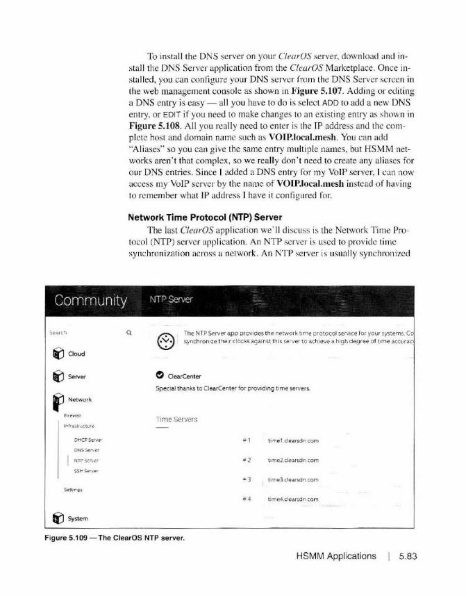
I
To install the DNS server on your ClearOS server, download and install the DNS Server application from the ClearOS Marketplace. Once installed, you can confi gure your DNS server from the DNS Server screen in the web management console as shown in F igure 5.107. Adding or editing a DNS entry is easy - all you have to do is select ADD to add a new DNS entry, or EDIT if you need to make changes to an existing entry as shown in Figure 5.108. All you really need to enter is the IP address and the complete host and domain name such as VOiP.iocai.mesh. You can add .. Aliases" so you can give the same entry multiple names, but HSMM networks aren't that complex, so we really don't need to create any al iases for our DNS entries. Since l added a DNS entry fo r my VoIP server, I can now access my VoIP server by the name of VOiP.iocai.mesh instead of having to remember what IP address I have it configured for.
Network Time Protocol (NTP) Server The last ClearOS application we' ll discuss is the Network Time Pro
tocol (NTP) server application. An NTP server is used to provide time synchronization across a network. An NTP server is usual ly synchron ized
Community \JP Server
li'.J Cloud
_, Server
~ Network
F1t~wa11
lnfra5tructur.e
DHCPSer.,rer
ONS Server
SSH '*rver
I() System
Q The NTP Server app provides the network time protocol service for your systems. C synchronize their clocks against th is server to achieve a high degree of tune accurac
~ OearCenter
Special thanks to ClearCenter for providing ttme servers.
Time Servers
.. 1 t1me1 clearsdn com
t1me2 clearsdn.com
• 3 ttme3 clearsdn.com
• 4 time4 clearsdn.com
Figure 5.109 - The ClearOS NTP server.
HSMM Applications 5.83
ClipBucket
5.84 Chapter 5
to highly accurate time servers on the public Internet, providing a source of accurate time on your HSMM network. You can configure the ClearOS DHCP Server to provide the address of your network NTP server, and on your BBHN/AREDN nodes you can edit the /etdinit.d/ntpclient configuration file to use a network NTP server for time synchronization. As with other ClearOS applications, download and install the NTP Server application . Figure 5.109 shows the NTP Server configuration screen if you choose to use d ifferent Internet NTP servers for your time reference. The difference between the NTP Server applicat ion and other ClearOS applications is that there is no addi tional configuration needed. Once you install the NTP Server application , you're done. Your ClearOS server is now providing the NTP service to your HSMM network.
There are many more applications you can install on the ClearOS server, but these are the basic ones you may want available on your HSMM network and there's just not enough space in one book to cover them all. There is one other thing to note before we leave the C/earOS platform. S ince ClearOS is based on the CentOS Linux distribution, you can also add other Linux applications to your ClearOS server that are not avai lable from the ClearOS marketplace. However, it is up to you to determine if the application you ' re try ing to install is compatible with the ClearOS system and to get it configured properly. Usually this will involve working at the Linux command-line level and manually editing the configuration files. That's why I prefer the ClearOS approach wi th the Marketplace and the web management console.
Now it 's time to move off the ClearOS server platform and talk about some other applications you may want to run on your HSMM network.
ClipBucket is an open source video and photo sharing application with a look and feel similar to YouTube. ClipBucket is based on the scripting and programming language PHP and is designed to be installed on a standard Linux server running the Apache web server. Typically, when I bui ld a ClipBucket server, J build it on a CentOS Linux server. Unfortunately, it is not an application available in the ClearOS Marketplace and the ClearOS distribution is just different enough from the standard CentOS Linux that I would prefer just to build it on a regular CentOS Linux server. Installing and configuring a CentOS Linux server to use with ClipBucket is not difficult, but space does not permit covering all of the installa tion steps for CentOS and C/ipBucket.
Instead, I recommend fo llowing the visual step-by-step ClipBucket installation instructions at either http://docs.clip-bucket.com/ClipBucketfaqs or http://www.fastcomet.com/tutorials/C/ipBucket/manual·instal-

Cil) CLIPBUCKET 1.1· u.ro
~ ,..ytobrofflc .. u t roun..lf
Collectcms Photos
'@':ul: ,f + .... ________ .,._~_ .. i.·'.''·-i' Cl RandomV:doos
Subt.crlptions
--·-~:vc• . ., • .IJ .. --
1:1 Random phaW•
~-JTU Teti 1 "'" n~ \t.ul•d #l'1 ·~··~•) !Pl<'!•ll• •
01111110 ..,.._.nrr.r·a •11.q ~ .. ~: "';c,.t, ·~ ·1
TOP 10 USERS
Figure 5.110 - The ClipBucket media server.
TeamSpeak
la tion. There arc also several YouTube videos that walk you through the ClipBucket install ation process, including several on how to install ClipBucket on a Wi11dmrs server.
Figu re 5.110 shows a worki ng ClipBttcket server. Users can easily upload. view, and download videos and photos on the ClipBttcket server, allowing you to easily share video and images across your HSMM network.
TeamSpeak is a basic VoIP application that is used by many onli ne gamers as a means of talking to each other. We can use Ten111Speak as a way to have multiple voice channels we can use to talk among users. TeamSpeak allows you to have public and private channels, as well as providing a conference environment where all users can speak with each
HSMM Applications 5.85

~onnections 8ookmarks Si:lf Permissions !cols ~ettings !::!:'£>
a T :-' -·~ •(x T G) ,,
;:? TeamSpeak JI[ Server
" Q Default Channel • KW5GP
Nickname: KWSGP ~ Version: 3.0.18. 2 [Stable] on li'lndows j 5 Onfone since: 1 second
§! Server Groups:
ls Server Adll'Wl
lJ Channel Group: Guest
6 < :7:07: 31 > Trying to connect to se" er on 10.242.255.97
0 < 17:07:31 > . L ... c·r·.::. ·:. -::- .=~ 5::1•• _., · , ' wv1N11. teamsoeak.com ...... ' ..=::.:-~~ 1 • .-":•'"' ;"! [ "Y
6 < 17:07:31 > Connected to Server: "TeamSpeak )I[ Server'"
~TeamSpeak]l[Server ~~tChamel i----
© News: !&) A Connected as KW SGP '9
Figure 5.111 - The TeamSpeak client
5.86 Chapter 5
other. In addition lo voice communication, TeamSpeak also allows keyboard-to-keyboard chat and fi le transfers between users or groups of users.
This would be ideal for a public service event or disaster where all of the va1ious agencies need a common place to communicate. All you need is a server confi gured to run the TeamSpeak application and the TeamSpeak client installed on the workstations. The TeamSpeak server runs on Windows, Mac OS X, and Linux. Installing the TeamSpeak server application is very easy - it just runs as a regular program on your server. On Windows, Tea111Speak cannot be configured to automatically start as a Windows service, but you can create a scheduled task to automatically start the TeamSpeak application whenever the server reboots. The TeamSpeak client can be installed on a Windows, Mac OS X, Linux, Android, or iOS device. Figure 5.111 shows the TeamSpeak client running on a Windows workstation.

TeamSpeak is free for non-commercial groups and individuals hosting a single TeamSpeak server with up to 32 c lients. Yo u can also get a "nonprofit" license at no cost which allows you to run up to two TeamSpeak servers with up to 5 12 clients. All you have to do to get the non-profit license is regi ster w ith TeamSpeak and provide a valid e-mail address.
Internet-Based Applications In addition to server-based applications you can nm on your HSMM
network, since you have the abi lity to link you r HSMM network with the public Internet, you can access a variety of Internet-based applications from your HSMM network. Today, many public service and emergency management agencies use web-based applications such as WebEOC, NC4 Team, and D4H among others. On the Amateur Radio side, you have EchoLink, A llStar, D-STAR, and WIRES-X that you can use to link to repeaters using the public Internet over your HSMM network. Many o f these Amateur Radio applications require a public Internet link at the repeater site itself. Since many repeaters are in remote locations, providing a public Internet connection to these locations is not always feasible. By placing an HSMM network node a t your repeater site, you can now provide Internet access to your repeater site and take advantage of the many Amateur Radio Internet-based applications.
Web-Based Public Service Applications If you are planning to use your HSMM network to provide di saster
assistance and relief you may want to link your HSMM network to the public Internet so you can allow the various re lief agencies access to their web-based Crisis Management System (CMS).
WebEOC is the CMS used by the Federal Emergency Management Agency (FEMA) for their emergency management processes and functions, in order to provide a comprehensive situa tional awareness solution for FEMA and their associated agencies. Other CMS systems used include NC4's £-Team Emergency Operations Ce/lfer solution and D4H's D4H Live. Having these applications available on your HSMM network would be invaluable to the vario us re lief agencies in their di saster relie f efforts.
Amateur Radio Web-Based Applications It seems like everyone these days is connecting their repeaters and
other radio gear to the public Internet w ith appl ications such as EchoLink, Automatic Packet Reporting System (APRS and DPRS), AllStar, D-STAR, Yaesu's WIRES-X, and Winlink 2000 just to name a rew. With Lhe ability to provide your repeater site with access to the public Internet over your HSMM network, you can now provide direct access for these
HSMM Applications I 5.87
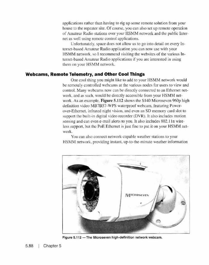
applications rather than having to rig up some remote soluti on from your house to the repeater site. Of course, you can also set up remote operation of Amateur Radio stations over your HSMM network and the public Internet as well using remote control applications.
Unfo111mately, space does not allow us to go into detail on every Internet-based Amateur Radio application you can now use with your HSMM network, so I recommend visiting the websites of the various Internet-based Amateur Radio applications if you are interested in using them on your HSMM network.
Webcams, Remote Telemetry, and Other Cool Things
5.88 Chapter 5
One cool thing you m ight like to add to your HSMM network would be remotely controlled webcams at the various nodes for users to view and control. Many webcams now can be directly connected to an Ethernet network, and as such, would be directly accessible from your HSMM network. As an example, Figure 5.112 shows the $ 140 Microseven 960p high definition video MB7B57-WPS waterproof webcam, featuring Powerover-Ethemet, in frared night vision, and even an SD memory card slo t to support the built-in digital video recorder <DVR). It also includes motion sensing and can even e-mai l alerts to you. It also includes 802. 11 n wireless support, but the PoE Ethernet is just fine to put it on your HSMM network.
You can also connect network-capable weather stations to your HSMM network, providing instant, up-to-the-minute weather information
MICR05EVEI\/ . /;
Figure 5.112 - The Microseven high-definition network webcam.

from the various nodes on your HSMM network. Using an Arduino or Raspbe1Ty Pi, you can create all kinds of remote control and telemetry projects that can be accessed from your HSMM network, including several Raspberry Pi-based applications such as a remote software defined radio (SDR) and Re11101eQTH for remote rig control.
The Raspberry Pi The Raspberry Pi (Figure 5.113) is a small, single-board Linux com
puter capable o r run ning many Amateur Radio applications such as EchoLink, software defined radio (SDR), D-STAR Access Point/Hotspot, or APRS iGate. Whi le not technically an Amateur Radi o applicati on. there 's even an ADS-B ai rcraft fli ght tracker.
Si nce the Raspberry Pi is an inexpensive Li11u.r-based computer with a built-in network adapter, it is ideally suited to be added to an HSMM network. There is even an impl ementation of HSMM fi rmware known as HSMM-Pi that allows you to use a RaspbetTy Pi and a USB WiFi adapter to create a Broadband-Hamnet version 3.1 compat ible node without having to purchase a Linksys WRT5.+G or Ubiqui ti wireless router. This could
Figure 5.113 - The Raspberry Pi.
HSMM Applications I 5.89

come in real handy when the day comes that you can't find any more compatible Linksys WRT54G routers.
Application Wrap-up
References
5.90 Chapter 5
As you can see, there are many applications and services that you can run on your HSMM network. I have tried to present a cross-section of the most common applications you may wish to run over your HSMM network, but thi s is j ust a small sampling of what is available.
That 's one of the nice things about having a TCP/IP-based network. With a Windows or Linux server, you can choose from thousands of applications for your HSMM network. And you' re not limited to the versions and d istributions we've covered in this chapter. These were chosen specifically for their ease of installation and use as you get started with your HSMM network.
As you get more familiar with the various applications, you may find another version that is more suitable to your needs or even a whole group of applicat ions I haven' t covered here. Hopefully, we 've finally answered that question of .. So what can I do with th is HSMM stuff?" and you 're ready to start deploying your own HSMM network.
www.allstarlink.org www.aprs.org www.aredn.org www.Asterisk.org www.Asteriskwin32.com www.broadband-hamnet.org www.clearfoundation.com www.ClearOS.com www.counterpath.com www.digium.com www.dstarinfo.com www.echolink.org www.FreePBX.org www.grandstream.com www.hamwan.org hsmmpi.wordpress.com www.igniterealtime.org www.microseven.com www.raspberrypi.org www.remoteshack.com www.sourceforge.net sysadminman .net/blog/2015/F reePBX-12-getti ng-started-guide-6627 www.TeamSpeak.com www.whichvoip.com/FreePBX-setup-tutorial .htm www.Webmin.com www.wikipedia.org www.winl ink.org www.yeasu.com
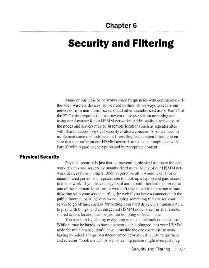
Chapter 6
Security and Filtering
Many of o ur HSMM networks share frequencies with commercia l offthe-shelf w ireless devices, so we need to think about ways to secure our networks from non-hams, hackers. and other unauthori zed users. Part 97 of the FCC rules requires that we prevent these users from accessing and us ing our Amateur Radio HSMM networks. Addi tionally, since some of the nodes and servers may be in remote locations such as repeater sites with shared access, physical security is also a concern . Also, we need to implement some methods such as fi rewall ing and content fi ltering to e nsure that the traffic on our HSMM network remains in compl iance with Part 97 with regard to encryption and inappropriate content.
Physical Security Physical security is j ust that - preventing physical access to the ne t
work devices and servers by unautho rized users. Many of our HSMM network devices have multiple Ethernet ports. so a ll it would take is for an unauthorized person at a repeater si te to hook up a laptop and gain access to the network. l f you leave a keyboard and monitor hooked to a server at o ne of these remote locations, it wouldn ' t take much for someone to start tinkering with your server, surfing the web if you have a connection to the public Internet , or at the very worst, doing something that causes your server to go oftline, such as formatting your hard drives. lt 's human nature to play with things. and an unsecured HSM M node or server at a remote. shared access location can be just too tempting to leave alone.
You can start by placing everything in a lockable rack or enclosure. W hile it may be handy to have a network cable plugged into your HSMM node for maintenance, don ' t leave it o utside the enclosure just to avoid having to unlock things. An unconnected network cable just hangs there and screams "hook me up." A well-meaning person might even just plug
Security and Filtering I 6.1

the loose end into your HSMM node thinking they were doing you a favor. That could create a switch loop that takes down the whole node. If you do leave a keyboard and monitor connected to your server, be sure to lock things down with a strong password. and if it has one. set the screen saver to lock the screen with a password.
Network Security Even with your nodes and servers physically secure, there is still the
risk of unauthorized access over the network. either from inside your HSMM network or from the public Internet if you have it connected to your HSMM network. Always use strong passwords on any device connected to your network. Amateurs arc unable to encrypt our data under Part 97 ru les. and this can be problematic if someone is able to sniff out your passwords <1\'cr the air. There's not a whole lot you can do about that.
Please note that there is some debate about whether or not hams can use encryption for HSMM network management functions. At this point it is best to eIT on the side of caution and not tempt fate or the FCC. Fortunate ly. standard users will be unable to connect to your network if you·re using the BBHN/AREDN or Ham WAN implementations, so even if they do get your passwords. there's not a whole lot they can do. This is all the more reason to use BBHN/AREDN or Ham WAN instead of plain old WiFi for your HSMM network.
Also, be sure tn turn off any unnecessary services. Disable, or use a firewal l to block access to, the ports you are not using but which may be availahle on your servers and other network devices. One example is Remote Desktop Protocol (RDP). The last thing you need is someone to remote in and have fun with the network at your expense.
Wireless Security
6.2 Chapter 6
In general. it 's j usl not a good idea to use standard WiFi for Amateur Rad io HSMM networks. If you have decided to use standard WiFi anyway, instead of the BBHN/AREDN or Ham WAN implementations, you do have the abili ty to use the standard WEP/WPA encryption methods. lf you do that. however, you are required to publ icly publish the keys. This is kind of like installing deadbolts on all your doors. and then telling everyone you keep the keys under the doo1111at. On top of that, a determined hacker can crack these keys in very short order. leaving your network as exposed as if you never had encryption in the first place.
Again, there is debate over whether or not you have to publish the actual keys or just disclose what encrypt ion method is being used. Until there is some official clarification regardi ng the use of encryption on Amateur Radio HSMM networks, we"ll err on the side of caution. Also, this still
means that you can ·t use encrypted SSL (Secure Sockets Layer) traffi c to
access secure websites, since that's another form of encryption completely separate from WEP/WPA encryption.
There are a few other things you can do. such as using MAC address filtering to only allow authorized devices on your network and disabli ng the Service Set Identifier (SSID) broadcasts that announce the presence of your WiFi network to the world. These will help hide and protect your network from the bad guys, but in the end. thL:y will find you and they will attempt to hack you .
You can also use the 5 GHz Part 97 channels to move away from the standard WiFi users. Agai n. odds are that eventually hackers will tind you. and using an out-of-band channel they" re not licensed for is not a concern to them.
One final consideration is that when you use standard WiFi . it falls to you to maintain Part 97 compliance with respect to identifying every I 0 minutes. The Amateur Radio HSMM implementations such as BBHN/ AREDN and Harn WAN take care of this for you. In the end, it 's just not a good idea to use standard WiFi for Amateur Radio HSMM networks.
BBHN and AREDN
Ham WAN
The BBH N and AREDN implementations offer a much belter solution when it comes to limiting access to your HSMM network. Each node must be using the same version of the fi rmware to commu nicate with each other. While standard WiFi users can see your network with a WiFi scan. they are unable to access it. Even if they can sniff out your clear-text passwords, they can't do anything with them unless tht:y gain physical access to a net work node. which is yet another reason to have good physical security.
Herc, your primary threat is from your users or from the public lnlernet if you have connected it to your HSMM network. Again, with the restriction on encryption. there's not a whole lot you can do to prevent one of your authorized users from hacking your m.:twork internally. You can enable logging on your network devices and servers so in the event something does happen, you may be able to trace it back to the user.
For threats coming from the public Internet. you should use a firewall, turn off any services, and block any ports you are not us ing. We can also use encryption for our Internet .. out-of-band" manage ment, so we can use things like SSL, Secure Shell (SS H), and virtual private networking (VPN). We' ll talk more about setting up fi rewalls and VPN connecti ons in a bit.
Of all the Amateur Radio HSMM implementations. Harn WAN is inherently the most secure when it comes to unaut horized access. No user can
Security and Filtering 6.3

gain access to your Ham WAN network without acquiring a valid security
certificate that is sent with each data packet. It is important to note that while encryption technology is used lo generate these security certificates, they are embedded inside the actual data packets. Without the private key used to generate a valid certificate, there is no feasible way to forge the certificate keys even though everything is sent in clear text. The ARRL Logbook of the World (LoTW) Certificate Authority is used to generate the certificates used in Ham WAN. ensuring that only licensed Amateur Radio operators can get a valid ceniticate. Since this ce11ificate is embedded within each data packet you send on the Ham WAN network, it is very difficult
for an unauthori zed user to ga in access to any of the network resources. Ham WAN also uses the Amateur Radio Part 97 channels in the 3.4 and
5 GHz bands. in part to reduce interference from standard WiFi users. This also adds a layer of obscurity by using these Part 97 channels that are generally not available on standard WiFi devices. As with the other implementations, physical secutity is still of major importance with a Ham WAN network, especially since the cell sites are often at a remote high point location with shared access.
Firewalls and Filtering If you arc planning to connect your HSMM network to the public In
ternet, it is a good idea to implement a firewall solution to block unauthorized access attempts and other traffic you don ' t want entering or leaving your HSMM network. At the same time, you will probably want to implement some form of content filtering to b lock websites deemed undesirable or that may be in violation of the Part 97 rules. A lthough the originating user who generates traffic in violation of the Part 97 rules is the one who is
ultimately held responsible, it still is incumbent on you to help do your part and block access to these bad things where possible.
Commercial firewalls such as the Cisco ASA , Barracuda BarraGuard, and Fo11inet\ Fortigate are great. but they tend to be a bit out of our price range. The same goes for Internet content filters such as iBoss, Ba.ITacuda's Web Filter. and Fortinet's Fortigate. Fortunately, there arc also several Linu.x firewall and content filter distributions we can use for free, among them IPCop. Coptilter, and our old friend, ClearOS. Naturally, since we're already familiar with CfearOS, we'll use it for our firewall and Internet filter. Most Linux firewalls and content filters are based on the built-in Linux Iptables module, the Squid web proxy, and the DansGuardian web filter applications.
The ClearOS Firewall
6.4 Chapter 6
In the last chapte r, we focused on using the CfearOS Linux distribution to build our applications servers wi th just a sing le network adapter.
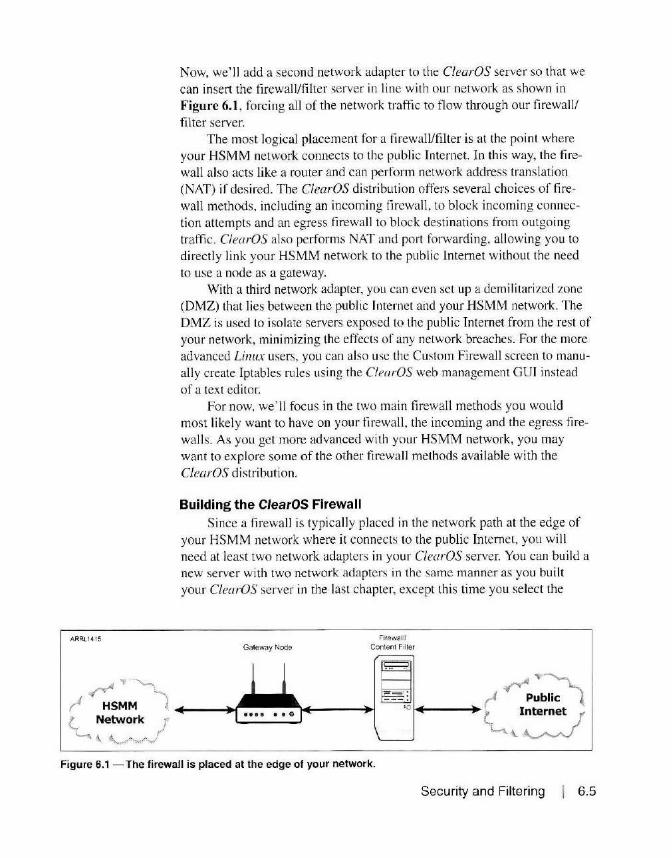
ARRL 14 15
Now, we' ll add a second network adapter to the ClearOS server so that we can insert the firewall/filter server in line with our network as shown in Figure 6.1 , forcing all of the network traffic to flow through our firewall/ filter server.
The most logical placement for a firewall/filter is at the point where your HSMM network connects to the public Internet. In this way, the firewall also acts like a router and can perform network address translation (NAT) if desi red. The ClearOS distribution offers several choices of firewall methods, including an incoming firewall , to block incoming connection attempts and an egress firewall to block destinations from outgoing traffic. C/earOS also performs NAT and port forwarding, allowing you to directly link your HSMM network to the public Internet without the need to use a node as a gateway.
With a third network adapter, you can even set up a demilitarized zone (DMZ) that lies between the public Internet and your HSMM network. The DMZ is used to isolate servers exposed to the public Internet from the rest of your network, minimizing the effects of any network breaches. For the more advanced Linux users, you can also use the Custom Firewall screen to manually create lptables rules using the C/earOS web management GUI instead of a text editor.
For now, we' ll focus in the two main firewall methods you would most likely want to have on your firewall , the incoming and the egress firewalls. As you get more advanced with your HSMM network, you may want to explore some of the other firewall methods available with the ClearOS distribution.
Building the ClearOS Firewall Since a firewall is typically placed in the network path at the edge of
your HSMM network where it connects to the public Internet, you will need at least two network adapters in your C/earOS server. You can build a new server with two network adapters in the same manner as you built your ClearOS server in the last chapter, except this time you select the
Gateway Node Firewall/
Content Filter
Figure 6.1 -The firewall is placed at the edge of your network.
Security and Filtering I 6.5

::.~:-:- ;<.;·_~--.~
' Registration
0: Configuration
b Ma.'icetpla.ce
5 Finish
Gateway Mode as shown in Figure 6.2. Another way is to add the second adapter to an existing ClearOS server, and it will automatically identify and install the new adapter. When adding an adapter, don't forget to set the Network Mode to Gateway Mode as shown in Figure 6.3. When configured in th is manner, the CleurOS server is performing the role of an "edge'' device. sitting between your HSMM network and the public Internet.
With the ClearOS server nmv performing the role of a firewall, it also acts as a router. able to do NAT. port forwarding. routing. and other edge device functions such as content filtering and VPN remote access. Since your ClearOS firewall is now also a router, you have to configure two IP addresses on separate networks on the server. To avoid confusion, we' ll refer to these as the External and LAN (internal) interfaces.
The first thing you will want to do is configure the first network adapter for the External role, if it is not already set, and the second network adapter for the LAN role as shown in Figures 6.4 through 6.6. Here's where a ll that TCP/IP routing stuff comes into play.
The External inte1face needs to be configured to interface with your public Internet router or modem. Typically, your internet service provider (ISP) assigns your External IP address via DHCP. so you most likely will
Net-Nork Mode
·OC> - ... : ; - ~~~ :-~ ....... .,. !.<"". '. •
_.-.,..
o;.e.Ners =p 5tat'<:'d u:1 ,, p'"o t.:-c:ea -;e r·.-. or.._,
fer >!'K°"'l"i» P. ,1n 0 1:1( £'< '1P~w;;rk Th(·
firewa. ~s o ~ll.~led +11 this rnxr
• • • • •
• Figure 6.2 - Selecting the Gateway Mode during installation.
6.6 Chapter 6

Community 1PSettings o settings
~ Cloud
li:J Gateway
li'.J Server
fl Network
Jrfra~ttucu·e
VP'\
I :?<:·:: N)';
Mv t•\'.A..._
Q ·- The IP Semngs app provides the tools to configu·e the most common network tasl<s O c:> serve,.s and network interface senings ~
Settings
Network Mode Gateway Mod•
Hostnarne KWSGP·Firewall lo~aLmesh
Internet Hostn.ame KWSGP·F1'ewa1Llocal mesh
Jefaul: Doma n local meso
.. Cancel
Figure 6.3 - Selecting the Gateway Mode when adding a network adapter to an existing server.
have your External in terface configured to use the DHCP information assigned by your ISP. You will need to configure the LAN interface with a static IP address that you wi ll use to link to your HSMM network .
Note that you are not g iven the oppo1tunity to configure a gateway address on the LAN interface. The ClearOS server will always use the External interface for its default gateway address. The External and LAN IP addresses must be on separate IP ·ubnels, since we can ' t have the same IP address range on two separate network segments.
If you are using a BBHN or AREDN node to link to the public Internet, you can use the WAN port on your node if one is avai lable. Since your C/earOS server now appears s imilar to your ISP's router or modem to your HSMM network, you can configure a private IP address on the LAN interface of your ClearOS server and set the WAN port on your to node to use DHCP.
If your HSMM network does not have WAN interface capabili ty, o r you are using Ham WAN, you will need to assign a valid static IP address on the LAN interface and configure the default route on your HSMM network to use the LAN IP address of the firewall as the gateway address.
Next, go to the ClearOS Marketplace to download and install the applications for your firewa ll. 1 usually install all of the firewall and re lated applications when building a firewall/content filtering server as shown in
Security and Filtering 6.7

Community 1P ~-oct11nss o i\ct\1. 0'~
ri'.1 Cloud
9i::J Gateway
l(J Server
IJ Network
!·e1,11. !
tiJ System
rii:J Reports
Q •- Tr e IP Setti r i;s 3.P~ cr o'(tde~ the : ools ;:o configure ~t1e mos~ commor. i":i!twor)( tasks 0 Cl serviers ano r.etworl.i +r, ~e 1fa.c e ser• ngs -©-
Ga:.eway Mode
KW5GP·F ~rewaH.locaJ mesh
K.WSGP-Frre-uaH local.mes.ti
Cf'.S
8 8.8 6
102422551
Add VlAN Interface Add Vllual lnterfllre
Link Interface . Role Tyl><!: IP Address Action
! e"f1S 33 b::ernal Sta~1 :: iO 242255 SS Ye< m Oolote • f enJ6 LAN No m
Figure 6.4 - Configuring the LAN (internal) interface.
6.8 Chapter 6
Figure 6.7. That way I can a lways e nable additional fi rewall features without having to access the Marketplace again.
If you a re planning to configure virtual private ne twork (VPN) access to your HSM M network via the public Internet, you may also want to install one of the VPN applications from the Marketplace. Also, as a general rule , I
always install the Directory and Web Server applications, in addition to the
Webrnin application on all of my ClearOS servers . We' ll talk a bit more on VPN in a bit.
You may have a lso noticed that I typically install the Intrusion De tec-

~Cloud
iJ Gateway
iJ server
fl Network
l(j Systam
Ii'.) Reports
·- Th e I P Settings app pro vid es :he toots to conri9>Jre t lie m ost common network tasks I O e::> ~rvers .end networ~ interfa ce se ttir9s _.....
Interface
Information
Settings I
Verdor 1m e 1 Corporation
8254SEM G19ab1: Ethernet Controller (Copper )
Bus PCJ
~ n k No
SP"<d 1000 t-lbts
lr :erfece ens36
.AN
IP Aacren 10 242 llJO I
Metma.sk l SS lSS 2SSO
. Cancel Figure 6.5 - Configuring the LAN interface IP Address.
tion System (IDS) and Intrusion Prevention System (JPS) as shown in Figures 6.8 and 6.9 when I build a ClearOS firewall server. The ClearOS lDS/ IPS system is based on the open source Snort and SnortSam applications. Snort is a network intrusion detection system that performs rea l-time packer analysis and logging of your network traffi c. Snort Sam is a plug-in for Snort that adds automatic IP address blocking for detected intrusion or hacking attempts. While the IDS and !PS applications are free in the ClearOS Marketplace, if you want IDS rules updates, you will need to purchase that feature. As a general rule, the basic IDS/JPS ru le set that comes
Security and Filtering 6.9
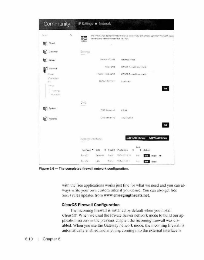
Community IP Sctt1n,~s o t\ctwcrk:
Q
rt(] Cloud
GJ:J: Gateway
QI) Server
F Network
,-:•,
•.•.•,,',.:.',
e(J System
lirJ RePort.s
·o= ~
cr.s
1,.e IPSett1nQsa.po proVlOe>~ the :oc1s : o cc.n'1our e: :he mos: commor retwori... t a.sits ~ers ano net~orti; 1n1e~rai::e !.e:: n9s
Hostr~iiie
Oe'a\.i : :o,,.l' .... local mesr
ease
'02~2 255 I
Add "1.AN lnterl8ce Add IMuai lntofface
Lmk
lr.terface . Role Type; IP Address Action
! er ~3 ~ C ~terriaJ S:a:1:: '02 -1 ~2555~ 'i'es m 0."<• • ! en30: .., At: S.:!::: ·i:1 :.:.:. I•:~ 1es m CROE-t•
Figure 6.6 - The completed firewall network configuration.
6. 10 Chapter 6
with the free applications works j ust tine ror what we need and you can always write your own custom rules if you desire. You can also get free Snorr rules updates from www.ernergingthreats.net.
ClearOS Firewall Configuration The incoming firewall is installed by default when you insta ll
ClearOS. When we used the Private Server network mode to build our application servers in the previous chapter, the incoming firewall was disabled. When you use the Gateway network mode, the incoming firewall is automatically enabled and anyth ing coming into the external interface is

C . -a ommunity '::10a'ns l/ar•.otp!ace 0 Install == l!!!!!J
Q
riiJ Cloud
ti) Network
tJ System
r'Qj Reports
• Clea·OS Mark~tpace is v.+ero:>: you car'I add l"lo.'.'V<. Jpp.;and wrvices ~o yo\.if sySi t! r'll Aopsavailable in the Mar'-etpla-:.e have gone through a str,ng<ent quality con! rol ptocess to ensure the quahty and !.s-<:unty of e1ar h ~1 1bm1 ss1ori
Deso1ptlon Pnce Unit Oiscou~ r btended EULA Action
1 t::il/', ;;,T r·,_.., ; 0.:-.0 ',,)')€' ED F ~ ..... ; i;.c:i.:. '-·::•1.;- E::!I FreE- ;ooo '«Jn<? ED l it.•\} $ l} ~)'} 'v :in.;. ED J:rpo. SCflll Non-:!' ED ~ "'.-<;'- s (; ~~_l 'J0 "'•'9' ED F•e(' !.OJI) :-..;.,'"II? l!ml F·('".' "! L YJ o::Jl"ll? l!ml ~ -c--: :; cOCi ,,,,,.~ l!ml C ·~"" " ) ) '•Ci''<: ED Fr':'-· 50 00 ~Q"'? l!ml fro:<" $ 0 00 N0'19 l!ml
V./cb Acee::.~ C c,-tro r,.,., 500) None l!ml ; , , .... 5. •.:.•C)) °'iO"'.e l!ml
Figure 6.7 - Selecting the firewall modules for installation.
blocked except for the ClearOS web management GUI on port 8 1 unless you specifically open the port to allow it. Figure 6.10 shows the Incoming Firewall management screen with port 10000 opened for Webmin access.
The Egress Firewall screen shown in Figure 6.11 is used to block outgoing traffic from your network. Using the Egress Firewall screen, you can set it one of two modes. You can I ) allow all outgoing traffic and specify the dest inat ion ports and/or the destination IP address or domain to block; or 2) block all outgoing traffic and specify only the destinations you wish to
allow. This would be ideal for shutting down access to encrypted https websites by blocking destination port 443 , where the majority of the encrypted SSL traffic occurs.
The C!earOS Gateway Mode server also has some other nice features more advanced users might find interesting. With the Bandwidth and Quality of Service (QoS) Manager. you can prioritize and control your traffic utilization. The Web Access Controls allow you to set traffic restrictions based on Time-of-Day. and the Multi-WAN feature allows you to have mul-
Security and Filtering 6.11

Community Intrusion Detection SystPm
Q Tne- advanced lnuus on Detect.on System apo performs security scanning a t the ner.
r(J Clood
t:J Gateway
Si..r'IJul 1903:20· \ 62015
525
Q'(J Network h .i t S·_·~., Ill
~ System Rules
Rule Set Oescr1pt1on : Action
llr:J Reports P:i :,
18 u
p2p LI
" [ 1\1.,~ • .., :- ts <;
57 it:
f:p 12 It.
Figure 6.8 - The ClearOS Intrusion Detection System.
6. 12 Chapter 6
tiple connections to the public lnlernet, allowing you to load balance your Internel traffic as well as providing for redundant paths to the Internet with automalic fail-over.
The ClearOS Content Filter The ClearOS Contenl Engine is used to block access to websites
based on sile b lacklisls, word phrase lists. an<l other criteria. Based o n the Linux Squid Caching Web Proxy and DansGuardian Content Filte r applicati ons. the ClearOS conlent Ii Ile r is easily managed using the ClearOS web management screens as shown in Figures 6.12 throug h 6.15. The Web Proxy server ac ts as an intermediary for web page requests coming from your HS MM network to the public Internet. caching the web page content and helping to reduce overall bandwidth usage. T he DansGuardian Content
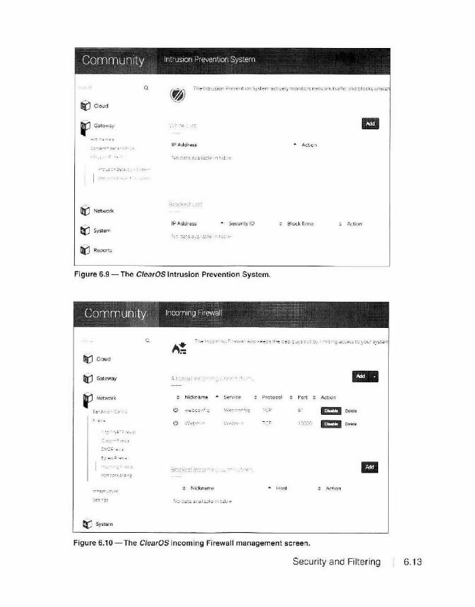
Community Intrusion Prevention System
Q The tnuusio n P1e'.1C~nt1on System dCtJvety monitors. ncf',••ori.. tr.iffn: ;o.nd blocks unw.ar
iJ Cloud
tJ Gat eway
.:..- '. -.<! ... l."C'
~ Network
fij System
rti:J Reports
IP Address
IP Address • Security !D
Figure 6.9 - The ClearOS Intrusion Prevention System.
Community Incoming Firewall
Q
Gi:J Cloud
r(:J Gate~ay
~ Network Nickname . Service Protocol
CJ .-;1?tv.:.on; g \/;'-":··~n·· fi<J TCP
CJ · ... ·:-:::-::...,... ' \'•~:;·1 ., T(C
c·.·z c ..... J.
Nickname • Host
t(J System
Ill • Actio n
Biock Time Action
Port Action
8 · m::I Odele
l ')))(r m::I Oelie1e
Actio n
Figure 6.10-The ClearOS Incoming Firewall management screen.
Security and Filtering 6.1 3
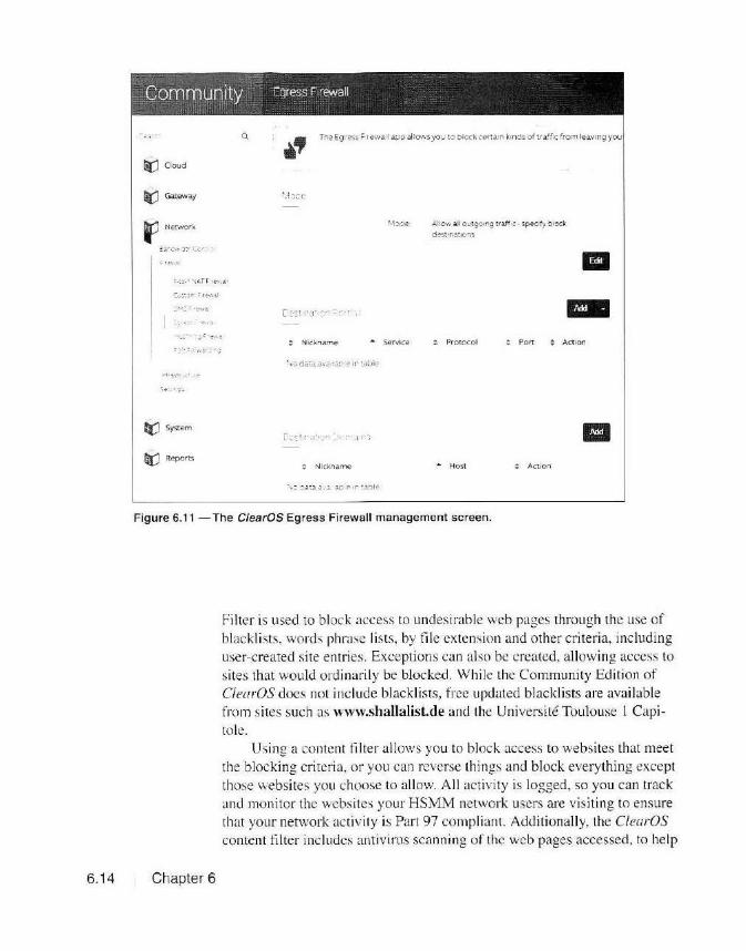
Community Egress Firewall
~Cloud
~ Gateway
~ Network
~a-.::1~ O~!- i:.: ·· ·1 ••
::t:J System
rQ:J Reports
Q ~· The Eg r»<S ~, rewall app al lows you to b io ck " ''""n kinds o f tralf<c from leaV>ng you
: Nickname ... Service
! Nickname
;..l:O'r·1 a.II outgcing traff.c ·specify block
di'st•nations
Protocol Port Action
.... Host Action
Figure 6.11 - The ClearOS Egress Firewall management screen.
6.14 Chapter 6
Fil ter is used to block access to undesirable web pages through the use of blacklists, words phrase lists, by file extension and other cri teria, including user-created site entries. Exceptions can also be created, allowing access to sites that would ordinarily be blocked. While the Community Edition of CfearOS does not include blacklists, free updated blackli sts are available from si tes such as www.shallalist.de and the Universite Toulouse l Capi to le.
Using a content filter a llows you to b lock access to websi tes that meet the blocking crite ria. or you can reverse things and block everything except those websites you choose to allow. A ll act ivity is logged, so you can track and monitor the websites your HSMM network users are visiting to ensure that your network activity is Pai1 97 compliant. Additionally, the C/earOS content filter inc ludes antivirus scanning o f the web pages accessed, to help

Community Web Proxy SeNer
0.
ri(J Cloud
F Gateway
:.r:l'""OL1•lfi
fl[) Network
ti? System
~ Reports
~ l "'e .Veoh r·ox1Ser.er~p.!::! as d'1 '":ierr1ev.a,..·; ro- web reQ-estsor Q r sM'lQ lrom ~ sec.e· m::u.y1~ p~ge ~:.:eu t ,....es ce:r~a~~~ can:h\· ::Stt· L.:se . .:. rd ~··o·."jes s :e M t
0 ~
D sabled
m
500"16
'-l:'P ............. : r - "·.r o: !:t S :e
Tuning
=-~ f,_ ..... ~·· :~ -~ • .:
You Tube for Sd1ools
IP.-M;§ifi
Figure 6.12-The C/earOSWeb Proxy Server management screen.
prevent viruses from attacking your HSMM network and users.
Virtual Private Networking (VPN) As we discussed earlier. there are advantages to being able to access
your HSMM network securely across the public Internet. While we can' t run encryption on our HSMM networks, there are no rest1ictions when using encrypted connections over the public Internet to access your HSMM network. A VPN connection creates a secure ··tunnel" across the public Internet, allowing you to securely connect remotely to your HSMM network
Security and Filte ring 6.15

ti:J Cloud
f Gateway
Q Tt1e (.:inten t r:il ter app a iicws af"l 3Cm ri.st· a~or to er"'f(11'~ ln ~er~N brows1ri.g pol1c1e
i,;5er·~pec 1 r~cd groups
(c - :~~ : : -~, 1'"' :>-: •
II[) Server
~Network.
tl'.J System
rQ:.J Reports
Policy Name Group Ac tion
m m
E%¥f+5
m
Figure 6.13 - The C/earOS Content Filter Engine management screen.
6.16 Chapter 6
with the same look and feel as if you are a connected to a switch directly on your HSMM network. The C/earOS server supports several types of VPN connections, including Open VPN, Point-To-Point VPN (PPTP), and lPsec. These applications are best run on the ClearOS server that is performing your firewall and NAT function s. Of these. PPTP is the easiest to configure and use to connect to your HSMM network from a remote workstation.
The IPsec VPN server applicatio ns offer up some interesting possibilities for connecting HSMM networks over the public Internet. Using !Psec, you can create a secure tunnel between your sites over the public internet to link sites and networks together. This cou ld be of use to link Ham WAN ce ll si tes together rather than setting up a separate w ireless link between cell sites, or serve as a redundant link if the inter-site wireless link goes down. Using the I Psec VPN server applicution , you can link HSMM net
works together from all over the world, c reating one big HSMM network. Again, since a VPN link uses the public internet, there are no restrictions

Community Content r11ter E:11g1ne o Policy
Q
Oi'.J Cloud
fl Gateway
The Content Filter app allows an administrator to enforce lnternei browsu across all users or user-specified groups
+;1•;:1..1..:1,;
General Settings
a1ackl1sts
Wib ~ccess. Cortro Phrase List s.
m m m m m m m m
MIME Types
Fiie Extensions
Sanned Snes
~Network Gray Sites
e('.J System Excepuon SJtes
Ii) Reports
Figure 6.14 - The C/earOS Content Filter Engine Policies management screen.
on encryption since your traffic is encrypted only over the VPN lin k, and then unencrypted before being passed on to the destination network.
Firewall Routing Finally, when your C!earOS server performs the function o f a router
when it is configured for the Gateway Network Mode, you may need to acid static routes to properly ro ute your network traffic. While Weh111i11 does offer the ability to configure static routes, the ClearOS implementation is just different enough from the standard Ce1110S Linux version that Web111i11 can't be used to permanently store these static routes. T his means that you will have to manually enter the routes for any static routes you want to be active permanently.
Figure 6.16 shows how to enter a static route on your ClearOS server. The file to edit is /etc/sysconfig/network-scripts/route-<interfacc name>. In my case this would be /etc/sysconfig/network-scripts/route-ens36 for the LAN interface on my ClearOS server. The l'irst time you go to create a static route, this file may not ex ist, so you wi ll need to create it. Each entry is in the fonnat shown in Fig ure 6. 16, wi th the Destination network IP
Security and Filtering 6.17

6.18
Community CrntHI' - l'er nc; nt- 0 __:._ . I" '
The Content Fil ter app allows an administrator to enforce Internet browsing pohcie 01 user·spec1f1ed 9ro1..ps
ri:J Cloud
tJ Gateway
,'l.r'I· ... .11 ""'-.t'~
,...., 9f::J Server
li(J Network
ti:J System
© Reports
Sett "'J
Filter Mooe Norma
Dyn~1m1c Scan Sens1t1v1ty A.gg ress1v-e
Repo1tmg Levtl Short Repor t
V1r _s Scan Er"\c)OIC(:I
Deep u;:~ 1.. Analysis E"aoi~
a:ock Jownlcads 01s.abled
31anket Block 01~bled
Block IP Don>a<ns 01\o!lbled
.. Cancel
Figure 6.15 - The CtearOS Content Filter Engine Settings screen.
Module Index
I etc/sysconfig/n etwork-sc ri pts/route-ens36
1 ADDRESS0=10 . 100 . 0 . 0
2 NETMASK0=255 . 255 . 0 . 0
3 GATEWAY0=10.242 . 100.2
4
Figure 6.16 - Adding a static IP rout ing entry.
Chapter 6
Edit file

[[email protected] webmin-1.7701# ip route default via 10 .242.255.1 dev ens33
Figure 6.17 -Displaying the active IP routes.
10.242.100.0/24 dev ens36 proto kernel scope link src 10.242.100.1 10.242.255. 0/24 dev ens33 proto kernel scope link src 10.242.255 .55 [[email protected] webmin - 1.7701# service netl.IJrk restart Restarting netl.IJrk (via systernctl): [ [[email protected] webmin- 1.7701# ip route default via 10.242.255.1 dev ens33 10.100.0.0/16 via 10.242.100.2 dev ens36 10.242.100.0/24 dev ens36 proto kernel scope link src 10.242.100.1 10.242.255 .0/24 dev ens33 proto kernel scope link src 10.242.255.55 [[email protected] webmin-1.7701#
Summary
address listed as ADDRESSO, the netmask for the route li sted as NETMASKO, and the Gateway IP address listed as GATEWAYO. The next emry would be ADDRESS I , NETMASKl, and GATEWAY I, and so on.
Once you have entered the static routes, you must restart the networking service or reboot your ClearOS server. To restart the network service, type "service network restart" on the server console. To display the currently active routes on your ClearOS server, type "ip route" at the ClearOS console. Figure 6.17 shows the active routes before and afte r restarting the network service, showing that it did indeed add the stati c route we created to the currently active routes.
As you have seen, there are a lot of things we can do to secure our HSMM networks and help our network users remain in compliance with the FCC Part 97 rules. In the next chapter, we'll look at ways on how to improve the reli abili ty and availability of our HSMM networks, including backups, redundancy, and virtualization.
Security and Filtering 6.19

References
6.20 Chapter 6
www.barracuda.com www.cisco.com www.clearfoundation.com www.clearos.com www.copfilter.org www.dansguardian.org dsi.ut-capitole.fr/blacklists www.emergingthreats.net www.fortinet.com www.iboss.com www.ipcop.org www.shallalist.de www.snort.org www.snortsam.net www.squid-cache.org www.wikipedia.org

Power
Chapter 7
Backup and Redundancy
As with any network, keeping everything up and running is of prime importance. This is a major consideration if you are pl anning for your HSMM network to be used for public service events and disaster suppo11. By its very definition, during a disaster every part of your network may or may not be fully operational. While you can't plan for every eventuality, you can take some steps to ensure that your HSMM network has some resiliency to remain available and operational as much as possible. Of course, in order to know what's not working, you will need some automated monitoring and management tools to let you know when th ings sta11 going haywire and lo alert you that there are issues with your HSMM network.
One of the first things to fa il in a disaster is often the electrical power. In addition, often the power at remote sites is not always the best. Devices such as servers don't do real well with naky power, so it's best to have all of your equipment connected to an uninten-uptible power supply (UPS). A UPS is an ac-to-dc-to-ac power inverter that uses batteries to maintain power during brief power outages. A UPS will also filter the incoming power and adjust for surges and brownouts, providing consistent, stable power to your equipment. You might want to consider some form of alternate power, such as a generator, to deal with extended power outages. Because the HSMM nodes themselves use so little power, you can use alternative methods such as solar power and batteries to provide backup power.
Backup and Redundancy 7 .1
Prepare for Failure Let's face iL things break. And they often break at the most inoppor
tune time. To prepare for such eventualiti es, you might want to have a
spare node and backup servers handy. Often the person replacing the equipment may not have a lot of expertise. Be sure to clearly label all ca
b les. networking equipment, and servers to show where they go and how they are connecteJ . Inc lude IP addresses and other important in formation to make equipment replacement easie r.
Have backups or all of your node and network configurations, as well as backups of all of your server data. I' ll say this again - make absolutely
certain that you have reliable backups of all of your configuratio ns and server data. You have no idea how many t imes I have had to work on a fa iled server and nobody bothered to keep the backups up-to-date. Other times I have had to fi gure out the VL AN configuration on a failed switch because nobody bothered to back up the switch configuration . You can even make remote backups across your HSMM network, so make sure you have a copy of these backups at a remote, safe location.
Redundancy and Virtualization
7.2 Chapter 7
Because you can have your application servers placed pretty much anywhere on your HSMM network. you might want to prepare a location housing a backup set of servers in case your main server locati on is dam
aged or offline. Before you stai1 adding up the cost of a bunch of servers, don't worry. There are some things you can do Lo significantly reduce the number of physical servers in your HSMM network. In fact , you can more than likely host all of your servers and applications on just one or two virtual host servers.
Virtualization technology is actually nothing new. It's been around since the 1960s and has long been used in mainframe computers. With virtualization. a physical computer is emulated entirely in software, comprised of nothing more than a group of files. This ·'virtual machine," or VM , appears to users to be a real physical system. In fact, with today's networked virtual mach ine technology, about the only way you can tell if a server is virtualized or not is by check ing the MAC address of the network adapter. To back up or move the VM "guest" to another host. a ll you have to do is copy the \' irtual machine files to the new host and off you go.
As you can sec. our virtual server is now comprised of nothing more than a group of files, so backing up and restoring systems is as easy as copying files. Gone are the days when you have to reinstall the operating system j ust so you can res tore from backups, or use disk imaging software to restore the system. And we all know how well some operating systems react when you try to restore them to diffe rent hardware, especially when

it comes to di sk contro llers. Since all or the physical system hardware is emulated in software by
the virtual host, you can freely move your virtual machines among all sorts of physical hardware, without worrying about hardware incompatibility or trying to find new drivers. Once a server is virtualized, no matter what physical hardware it's running on, it sees the same virtual environment and just keeps rolling right along. Also, with virtualization, each VM is in its own little world and can't interact with the other VMs. You can "power on" or reset a virtual machine and it wi ll have no effect on the other VMs running on the same host.
Virtualization allows you lo run multiple virtual servers on one physical virtual host. VMware 's VSphere 6 can run up to I 024 vi rtual machines on a single host. Now. while any server that has enough CPU horsepower and memory to run that many virtual machines is most likely well beyond the reach o f our budgets, for the number of servers we're probably goi ng to have on our HSMM networks, we can more than likely get away with just a couple of average servers , or even just large workstations.
For example, you can comfortably run multiple vi rtual servers on just your average quad-core CPU with 8 GB of RAM and a I TB or so hard drive. The main limitation is that you need enough physical memory to match the require ments of the virtual guests. While some of the modern "hypervisors" (virtual machine managers) can handle swapping and sharing memory between virtual machines, it 's best to have enough memory for each guest to have what it needs reserved for it in the host physical memory.
Another advantage of some hypervisors is the ability to take multiple '"snapshots" of your virtual guests. Snapshots are similar to system restore points in Windows. except snapshots a llow yo u to return to the exact system stale at the time the snapshot was taken. This is handy for a quick system backup just before you try to upgrade your server with untried software. You can even format the virtual guest' s hard drive, and reverting to a snapshot w ill res tore all of your data as if nothing ever happened .
One major advantage of virtualization is that you can mix and match the operating systems on your guest v irtual machines. You can simultaneously run multiple Windm1·s. Linux, Nm·ell. Sun Solari.» and other operating systems on the same vil1Lial host.
Virtualization Software And now for the best part. A lot of the virtualization software is free.
VMware's VStJhere ESXi 6 has a free version - all you have to do is register to get a serial number (see Figure 7.1). VMware ESXi is what is known as a "bare-meta l" hypervi sor, meaning that you install it as the op-
Backup and Redundancy 7 .3

e 1on 11 {?J A'~hST [/) U(SO-DCI
~ DCSO-OCl--0~ [tJ Oobuc~et [.}) OO?~S'\.N [D 2c""'°'ts
Figure 7.1 - VMware VSphere host running six virtual machines.
7.4 Chapter 7
erating system on a physical se rver. The major diffe rence between the free and paid vers ion is that you don ' t get the software application interfaces for storage and backups with the l'ree version. There arc other methods you can use to back up your virtual machines on an FSXi host and since we're no t planning to run expensi ve iSCSI or network-attached drives, we really don't need the storage APls e ither.
VMware a lso offers VM1rnre Workstotion for Wi11dm\'s and VMware Fusion for Mac OS. which are designed to run virtual machines on a standard workstation. I use VM11·are Workstation extensively for work, doing a lot of my development and testing in a virtual environment without the worry of having lo reinstall my workstation if I se riously mess things up. By taking snapshots along the way. I can always "revert" back to a point bel'ore l broke things. VMware also offers the free VMware Converter,

which you can use to easily convert your physical servers to vi11ual machines.
Starting with Windows Server 2008, Microsoft includes the free Hyper-V hypervi sor that runs under the Windo ws host. Hyper-V supports Windows and some Linux virtual machine guests. However, since you have to buy a server license, technically this isn't a free solution, but it is one of the more common virtualization technologies in use today.
There are a number of free open source hypervisors for Linux systems. In fact, VMware 's ESXi runs a small , customized version of Linux as its hypervisor. Some of the more well-known Linux hypervisors are KVM, Oracle's Virtua/Box , and Xen .
Network Monitoring With al l of the services and applications we have running on our
HSMM networks, it's not easy to keep track of everything and to know when there are problems with the network. For this task, we can use one of several free network monitoring applications to keep tabs on the status of the network and alert us when something goes wrong. Most modern network devices such as routers, switches, and servers are capable of running the Simple Network Monitoring Protocol (SNMP) that we can use to monitor the heal th of our network.
PRTC Nerwork Monitor is a network and bandwidth moni toring application that supports up to 100 network sensors in the free version. Devices are monitored using the SNMP or NetFlow protocols. and PRTC can be set up to send status alerts via email and SMS, as wel l as show alerts on the management console. Spiceworks is another very good free network monitoring and bandwidth monitoring app lication s imilar to PRTG without any limit to the number of sensors you can monitor. For indepth health status of your servers, SolarWinds offers a free Health Monitor application that can monitor up to fi ve servers, including VMware
Figure 7.2 -The Angel Network Monitor.
Backup and Redundancy 7.5

ESXi YM host servers. Other free SNMP network monitoring applications include Nagios and Zabbix.
If you want a very simple up/dow n status monitor, the Linux-based Angel NeTn:ork MoniTOr (Figure 7.2) is written in Perl and easily customizable with a minimum of programming expertise. Rather than use SN MP to monitor the network devices, every few minutes Angel pings your ne twork devices severa l times and also verities that it can connect to the various ports you have config ured for it to check. The resulting status is then displayed as a web page o n your web serve r.
Redundant Links
Summary
7.6 I Chapter 7
One o f the major weak points in any HSM M network is the wireless links between the various nodes. Atmospheri c conditions such as rain and fog can p lay havoc with microwave li nks. With the self-discovering and self-healing features of the BBHN/AREDN implementatio n, as long as yo u have an alternate path to a destination, your ne twork will remain operational , a lthoug h there may be so me degradation in throug hput by having to use a non-opti mal path to the destinatio n. S ince Ham WAN uses the Open Sho11est Path First (OSPF) routing protocol, if a backup path ex ists. the network will automatically switch over to it in the event a primary link fa ils.
Of course. a ll of th is is dependent on having backup links available . W hen designing your HSMM network. you should plan and implement backup paths for all of your critical nodes. Through the use of VPN technology (di scussed in Chapter 6). you can also use the public Internet as a link between your critical nodes, assuming of course that the nodes involved have access to the public Internet.
Managing and monitoring your network is a vital part of running an HSMM network. With all of the applicat io ns and services running on your HSMM network. it is important to know the status of your network. particularly if you ;,u-e running mission-cri tical applications for public service events and d isaster support. W ith our HSMM networks using advanced technology, th ings can, and will , break. We need to do our best to prepare for these eventuali ties the best that we can, keeping good backups of our network servers and having a plan of attack for w hen the bad stuff happens.
Ir's really not all that difficult. Like anything else, all you really need is a plan. Take the time to document your network and have your backup systems in place. With the way our HSMM networks Me designed, if a server does fa il , you can quick ly remote in to the backup server and bring

References
it online as needed. Since everything in our network is interconnected. we can do all of this from one central location without having to make that midnight uip ro the repeater site in bad weather.
Now that we ·ve got all of the pieces figured out and have determined what we want our networks to do. it"s time to start deploying our HSMM network and bring it a ll together.
www.linux-kvm.org www.microsoft.com www.nagios.org www.paessler.com www.solarwinds.com www.sourceforge.neUprojects/angel www.spiceworks.com www.virtualbox.org www.vmware.com www.wikipedia.org www.xenproject.org www.zabbix.com
Backup and Redundancy 7.7

Chapter 8
Deploying HSMM
And now we're finally he re. It 's time to start plan ning and building out your HSMM ne twork. The first thi ng you need to do is to decide which technology and frequencies you p lan to use. For those j ust sta rting out, the BBHN implementation u ing repurposed Link.sys WRT54G routers is the quickest, least expensive, and easiest way to get started. Howev
er, since the 2.4 G Hz WiFi band is shared with s tandard WiFi users, your network performance may suffer, particularly if you decide to p lace a cen
tral node on a hig h point such as a tall building, tower, or mountain . You may want lo start with the Linksys routers just to get the feel for how an HSMM network operates, but more than likely you will eventually want to move up to the qu iete r and less c rowded Pa rt 97 portions of the 5 G Hz
band. lf you have decided to go straight to 5 G Hz. your next decision is
w hethe r to use the BBHN, AREDN, o r Ham WAN implementations. The choice as to which technology to use wi ll most likely be based on several facto rs inc luding the choice of network topology, availab le equipment, and w hat Amateur Radio HSMM networks may already exist in your area. At the time th is book is written (late 20 15/early 20 16), whether to use the BBHN or AREDN implementations is pretty much a matte r of individual choice. T here is currently little functi ona l d iffe rence between the two. T he technology of both of these implementat ions is constantly changing, and at some point, each implementation more than li ke ly will have features that the o ther does not. Those differences may infl uence your decision one way or the other. I recommend staying up-to-date by visiting the websites of both irnplemc nLat ions when it comes time to choose.
Deploying HSMM I 8.1

... tl C>
~ "'
650
(]) 600 '° 'iii :l..= 550 ff) w o~ ...J-' 500 ~ I o~ 450 ~~ ~" 400 "'c Q; .. C'. n.
350 ~~ - ~ I'°" 300 u "' !:! 250 ;;; E 0 z
SPLA-1 Pa!ll P--o~ I C 8e:ween KWSGP ano Mem-Hil (52 45• aw ru:h) With F rs! <=resnel Zone
-
L.--- ·. .:_~-· "
0
. .
Pcint-to-Po1ni Profile -Line of S.ght Path _.,,.-.
Earth's Curvature Contpur First Fresnel Zone (5900 OOO·~Hz)
60% of First Fresnel Zone
. ...... ·'
" 10
Remember. the major advantage to the BBHN/AREDN technology is the self-discovering, self-advertising, self-healing network features, with the abi lity for any node to relay through any other node that it can see. In my case, living in Mississippi where we have no mountains and limited access to high buildings and towers. and with large areas of flat te1nin interspersed with just enough hills to cause issues with the
Dstance Betwee·1 KW~GP and Mem- HIL I 10 78 miles) longer paths, the ability to link through other nodes using
Figure 8.1 - A SPLAT! path profile graph. BBH N/AREDN could prove to
be a decidi ng factor. If I li ved in a mountainous area, the factors
used to choose the HSMM technology would be much different than the ones I am faced with here.
If you are in an area where your users all have communication paths to central. high points such as mountains. tall buildings, or towers. HamWAN would most likely be the technology of choice. Ham WAN offers a higher overall network throughput with direct wireless links to the central cell sites rather than needing to link through other client nodes to communicate with other users on the network.
In the end, the choice of which HSMM technology to use is up to you. Naturall y, if there is already an existing Amateur Radio HS MM network operating in your area, you •vould probably want to link into their network. whichever technology it uses.
Wireless Path Planning
8.2 Chapter 8
Before you go hooking things up and start trying to link with your fell ow networking hams. you should verify that the paths between your users are viable. You may need additional nodes or cell sites to provide coverage to all users. Fortunately, there are several free resources you can use to map out your network and create a "path profi le" to determine if the wireless path between two nodes is feasible. or what it will take to make the link feasible.
SPLAT' is a free Linux-based RF propagation and terrain analysis tool that can be used to calcul ate path profi les from 20 MHz to 20 GHz. Origi-

--== [ SPLAT! v: . 2 . 3 ?a th Analysis j ==--
T ransmitte r s : te : Mem- HIL Site locat:..on : 35 . 1050 Nort:h I 89 . 8688 ~lest (35° 6 ' 17 " NI 89 ° 52 ' 7 " W) Ground eleva t i on : 308 . 4 0 feet AMSL Antenna height : 328 . 08 f eet AGL I 636 . 48 feet AMSL Distance to KW5GP : 10 . 78 miles Azimuth to KW5GP : 232 . 54 degrees Depression angle to ~WSGP : - 0 . 3835 degrees
Receiver site : KW5GP Site locat:..on : 35 . 0100 No:-Lh I 90 . 0200 West (35° 0 ' 35" NI 90 ° l ' 11 " W) Ground elevat i on : 298 . 5 6 feet AMSL Antenna height : 34 . 45 feet AGL I 333 . 0: : ee t A.MSL ~ istance :o Mem-HIL : 10 . 78 ~:..les
Azimuth to ~em - r.:L : 52 . 45 degrees Slevation angle co Mem- HI: : +0 . 2275 degrees
Longley-Rice pa th calculation parameters used in this analysis:
Ea rth ' s Dielectric Constan t : 15 . 000 Ea r t h ' s Conductivity : 0 . 005 Siemens/mete r Atmospher ic Bendi ng Constan t (N- u ni Ls ) : 30 1 . 000 ppm Frequency : 300 . 000 MHz Radio Cli~ate : 5 (Continental ~emperate) Polarization : 0 (Hori zont al) Fraction of Situations : 50 . 0* Fraction of Time : 50 . 0%
Summary ~or ~he : i n :~ between Mem- HI L a nd :(l.•15GP :
Free s pa ce path loss : 106 . 80 dB Longley-Rice path loss : 109 .8 6 dB Attenuation due to effects of terrain : 3 . 07 dB Mod e of p r opaga t i o n : Line-Of-S ight Mode
No obstruction s to LOS path due to terrain were detected b y SPLAT '
Antenna a: ~W5GP m~st be raised to at least :sr . 45 :eet AGL co clear the fi~s~ Fresnel zone .
Antenna at KWS GP must be ~aised Lo at :east 77 . 45 ~~et AGL co clear 60 % o: the fi r st F res~e l zone .
Figure 8.2 - A detailed SPLAT! path analysis.
Deploying HSMM 8.3

nally developed for Li1111x by John A. M agliacane, KD2B D, there is now a version developed by John McMellen, KC0FLR. and Austin Wright, VE3NCQ, that runs on Windows. SPLAT! provides a graphical representation of the RF path and the teJTain between locations, including calculation of the Fresnel (pronounced "Fray-nell") zones, antenna bearings, and other important information about the proposed RF path. See the sidebar for more on Fresne l zones and why they' re so impo11ant to path profiling. SPLAT' runs from the command line and produces complete reports and a graphical representat ion of the RF path as shown in Figures 8.1 and 8.2. SPLAT' can also be used to calculate and di splay the calculated coverage area of a site or sites overlaid on the terrain map.
Fresnel Zones A key part of RF path profiling is determin
ing the Fresnel zones along the desi red RF path. While you would think that communications would be optimal if there is a clear line-of-sight path between sites, at microwave frequencies you also have to take into account the reflections along the path. These reflections can either add to or subtract from the effective signal strength depending on the phase of the reflected signal.
As the microwave signal travels along the intended path, the signal broadens until it begins to be reflected by obstacles in the path and the terrain itself. If the reflected path is one-half of the wavelength , the out-of-phase reflected signal will work to cancel out the direct signal. If the reflected path is less than a half-wavelength, it actually adds to the direct signal, improving the overall signal strength. These points of reflected signals create what is known as a Fresnel zone. and can be used to calculate the overall signal strength of the projected RF path.
There are many Fresnel zones created along the RF path, but of primary concern is the first zone, where the reflected signal helps to improve the signal strength. If the first Fresnel zone is blocked by an obstruction such as a building, tree, or ridge, we lose some of that additive effect. While it is not required that the entire Fresnel zone be clear of obstructions, it is desirable that at least 60% of the desired RF path is unobstructed to obtain the optimal RF path.
L__ _ ____ _
8.4 Chapter 8
SPLAT! can provide some very detailed information, but it requires that you download and convert the various terrain map liles you will need to generate the profiles based on the US Geological Survey Digita l Elevation Models (DEMs) or the Space Shuttle Radar Topography Mission (SRTM) Version 2 map files. The USGS is no longer offering the Digital Elevation Models, but they are still ava ilable for free from data. geocomm.com/dem. The SRTM data fi les are more accurate, but you must download the individual files for the areas you wish to map from https://dds.cr.usgs.gov/srtm/. Once you get used to using the command line for creating path profi les using SPLAT!. you will find it is a very powerful path analysis tool.
If you don' t want to mess with downloading te1rnin fil es o r working from the command line. the Ubiquiti Link Calcu lator is an easy to use web-based path profi ling tool. While it docs not provide the detailed path analysis available wi th SPLAT', it is a quick and easy method to plot a path profile as shown in Figure 8.3.
Another excellent web-based path proliling tool is Radio Mobile 011/ine. There is also a Wi11doll's version you can use to create a highl y detailed tc ITain graph and path analysis as shown in Figures 8.4 and 8.5.

{-- C t.1·11~ didink.ubnt.com tr
l"'~ ....... , ~ .. !;;r~"':; .
. 'f' Go gle
i
.I ~ r\,_ . §
.. @ ~iJ l \ Oht 8 1-YKh
11ap-:!•"• <S:e1~ i • ft••.,ofU•• -·~~'11-1~t~..-
\. r; • .,, ' ,__. ' ''°"""'·~·
'
G itAJION
-~ 70:7dBm
f.outiorl
"l~'"~ul.!l: ll ~'S'la!C'.
•
• •
.. . ()
. ; • ·' . ..
Figure 8.3 -The Ubiquiti Link Calculator.
Radio Mobile Online will also creale a coverage map for each location you wish to profile as shown in Figure 8.6.
Now that you've profiled your paths. ifs lime to start getting the gear ready lo go. We' ll start with setting up the L inksys W RT54G for BBHN.
Installing BBHN Firmware on the Linksys WRT54G Replacing the Linksys WRT54G factory firmware with the BBH N
firmware is as simple as performing a regular fim1ware update. Afler verifying that your Linksys router is compatible wi th the BBHN firmware, download the latest version from the Broadband-Hamnet website to your workstat ion. At th is point, 1 like to isolate my workstation and the Linksys router from the rest of my network to prevent conflicts with the Li nksys router's DHCP and my home network router's DHCP. To do that , simply
Deploying HSMM 8.5

KJ]ID( I ) L ~tirnde
Lous:ttude Ground dr1;;1oou
.~am ht:\,lbt
Anmulb Tilt R:iulio !io)"~t rm
TX pO\\ ct
TXhnelou TX :ll'ltetul.11:llll
RX:lnlOllU.&.Jm R..X luLelou R.'X«mlh\'l~·
Pt rfonnanu Oi\Unc•
Precis1ou ; l efj\l(llC\'
lSl.O~dB
Equw;iltul llotropic:llly Ridl.ttedPower S:-~1empm Required rclubtlny ~-,---~---~~---~~~~~~~~~~~~~~ ... ·0000"''~~~~·1
Rece.\ ed S1tn)J .7JJ4d!lm Rem\·ed S11tu1 F:idt :\lariln
-----~~-~~-~~~~ ......... ~~~~~~-'J~ds'C-~~~-1
Figure 8.4 - A Radio Mobile Online path profile.
:.-.·······..... •-. J!~···~ '.l... /'~ .. ·· ... /'Kt•\ ~_.....-•-. ........ ·· l' I ,-\: ~" ~_,-,.---
-+ ! _v.~1 J , ...
'-.,"; ,,~~ .. dUl(\}µ__.J~~,.!l-ll)~2'0---..] -~' · \t" ~" ~I r . ~ .. v. \ .I,..
) ., --- ~1.1
' \ \ 1"!' i t
I I ~·~ ~ ""',, ' 1Wl15. '""'"'
'! r~n
I ._ ....... .
··---.... -:.._ ______ #_#1·r
' ·:·-· ··
\"\ \
...... ...... . . .. .... .... ,- 11···· ··~•; ....... \ .. .. . .... . .. · ····-'-··· · ····· ······················ '--~,-...~ ,, +
+ ~I" '\ 1~·:,t;;•. -
'• .. I, ' j \. ~. 1~~~ ~ MSic>_--~
Figure 8.5 - Map of the path to be analyzed.
8.6 Chapter 8

\ •.. ,..-- .;~
,. ~-· ~--n 9 \ ...
· - _.....,
"'""
Ca,.~ "''m I '=t
@ @
© a..-
GJ ....... """"-' .......
C"
@~~,_, ........ . 11...t.:·.,
...... Figure 8.6 - Radio Mobile Online coverage map.
Upgrade f irmware
Firmware Upgrade Please select t1 ti~ to ur;>grade
j Browse I bbhn-3.1 O-wn54g-2 4-squashfs b in W.\1111111_1· 1 ·• •: ·• '"'T ,,,.,· -- ' .~•·: "-~ ... .1• r .. .., . - : ·
--·: --.c ...
t l1 •11t .1•I·· 1111 •" ' 110 1 h .. 1r1t c r1 uptcd;
Figure 8.7 - Loading the BBHN firmware to the Linksys WRT54G.
+
Deploying HSMM 8.7

Firmware Upgrade Pleese select ai 111e to upgrade
I Browse .• I bbhn-3 1.0-wrt54g-2 4·squoshts b in \\l,lf ll ll HI'. ; ;· -, !'~' l ft'Tft :ol'":' ri;:i , '. "''·"' -, · .- ,- f".J°l..,; , ":',. • ! ,
plug your workstation's Ethernet cable into one of the LAN ports on the Linksys router. Your workstat ion should get an IP address via DHC P from the Linksys router and you're ready to load the fi rmware.
1111111
U1M11.1dr· muM UOT he ml f"r 1 uptetl :
Figure 8.8 - The BBHN firmware upgrade in progress.
Browse to the Linksys router's web console, usually at J 92. 168.1. 1 for the default Linksys configuration. From there, go to the Administration screen and select the FIRMWARE UPDATE tab as shown in Figure 8.8. Select the BROWSE button and locate the BBHN firmware tile on your workstation and then select UPGRADE. The file will be
Upgrade is successful. uploaded and installed on the rou ter, and if all goes well. you will see the progress bars (Figure 8.8) and then the Upgrade Successful screen shown in
I Continue J
Figure 8.9 . When you select CONTIN
Figure 8.9 - A successful BBHN firmware upgrade.
UE, the router will reboot and is now running the BBHN firmware.
8.8 Chapter 8
That's all there is to it. Your Link.sys router is now running the
BBHN firmware and is ready to be configured . If you haven ' t already done so , isolate your workstation and the Linksys route r from the rest o f your home network to complete the configuration so that you get DHCP and DNS infonn ation from your new BBHN node. This is important because you don' t want to have to figure out the JP address of your BBHN node: instead. you'll access it using its DNS name. O pen a web browser and browse to http://localnode.local.mesh:8080. You should see the screen shown in Figure 8.10. Select setup and log in as " root'', with the password "hsmm''. You' ll be able to change thi s password to whatever you want as part of the node configuration.
On the Basic Setup screen, you assign the node name, wh ich wil l be usually your call sign or your call s ign plus a number as shown in Figure 8.11 . Here is where you can change the password for your node and select the node type. In addition to being a standard BBHN node, you can also choose to use your BBH N node as a Mesh Access Point. a Standard WiF i Access Point. a standard Wireless Client, or as a Wired Router using only the LAN and WAN interfaces with the wireless interface disabled . These are more advanced configuration modes that you won' t generally be
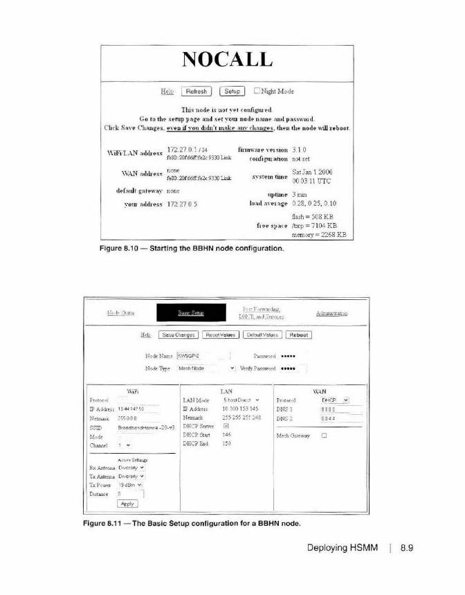
NOCALL Heb [ Refresh j [ Setup J 0 Night M ode
This node is not yet roufigm ed Go to the sentp paie 011d set yom uocle notne and password.
C'lirk So,·e Changes . eYeH if vou clidu't tnoke auv rhauges, then the node "ill l'eboot.
WiFi'L-\N ocl<lress 172·270·1 124 fe 80::20f.66ff.fe2c 9330 Link
fmnwaie ,·e1 siou 3. 1 0 ronfigmation not set
\\:.\N nclcb·e.~~ none fe80:.20f:66tl'fe2c9330 Link
Sat Jan 1 2000 00 031 1 UTC
default gateway none
vom· aclclress 172.27 0 5
nptiJ.ne 3 mm load aveuge 0.28, 0 25, 0 10
flash= 508 KB free spare ltmp =7 104 KB
memory = 2268 KB
Figure 8.1 O - Starting the BBHN node configuration.
Node Name [KwsGP-2
Node Type Me•h Node
\\~Fi
Pr-0tocol
IP Add:ess 10 44147 50
Netmas'.< 255 0 0 0
SSID BroedbendHemr e · 20· 'J3
Mode
Channel 1 v
A ctive S~ttlngs
Rx An:enna 0Ner sitt v
T x Anterma Diversity v
Tx Power 19dBm ..,
Distance 0
~
LAN Mode
IP Address
Netmask
DECP Seiv"
DHCP Stan
DHCPEnd
t"t:-: f,r.v:ll<lu_ig,
Qll.. 't __ .u1•l _..:::_er--1 .. e::
Password
v Venfy Password
LAN 5 hos1 Ouect v Protocol
JO JOO J53 145 DNS J
255 255 25'. ~48 DNS ~
El J4C Mesh Gateway
150
\\~
DHCP
8 BB 8
8 844
0
Figure 8.11 - The Basic Setup configuration for a BBHN node.
Deploying HSMM 8.9

using. so leave the node type as Mesh Node. On the setup screen. you can also select the LAN mode. which can be 1,
S, or 13 host direct, or you can select NAT. Typically, you will leave the LM T mode at the default of S host direct. If you select the NAT mode, you will need to assign a valid IP address and subnet, as well as create port forwarding rules for any devices on your LAN that will be accessed from the HSMM network. It 's usually best to leave this setting in one of the direct modes unless you have a specific reason to change it.
You also have the option to disable the built-in DHCP server on your node. Usually, you will want to leave this enabled so that your LAN devices receive their IP information from your node's DHCP server. lf you are running a server or other device that uses static IP addressing, you may want to ei ther disable the DHCP server and use static addressing on all of your LAN devices; modify the DHCP range and place your static devices outside of the DHCP range; or set up a DHCP reservation on the Po11 Forwarding, DHCP, and Servers configuration screen.
You wi ll notice that the WiFi and LAN IP addresses are pre-assigned. These addresses are determined based on the last three segments of the interface's MAC address. This is done to provide what theoretically should be unique IP addresses withi n your HSMM network. If, on the odd chance that another node on your HSMM network has the same last three segments of the MAC address as your node. you can change these to a differem address. In general, you can take the default settings and everything should be just fi ne.
The WAN settings are used to connect your node to the pub lic Internet. Typically, this will be set to use DHCP to get the proper IP address in-
KW5GP-2 !:!Ell I Refre•h ) J Mesh St•tu• J J OLSR St•tus I I WiFi Sc•n ) ~ ONight Mode
w if· kb 1044. 147.5018 SignallNoi,e,R.11io - ~O 1-90 120 dB ~ ·
1 "' 'P« fe80 20f:661T'fe2':9332 Link
10 100 153 145 /29 LAN otkh1'« fe80 20f661Ho2':9330 Link
f ill.m \":lt? YeI~ion 3 I 0 conrigwn1io11 mesh
. Sat Jan I 2000 'J"l• m nme 00 03 45 UTC
defoull ~ren";ly none
)'OUI"Orldre« 10 100 153 149
uptim• 3 mll1
lood a>1'r.lgt' 0 35. 0 20. 0 09
flash • 496 KB fr•• "J>OCO /Imp - 7060 KB
memory - 2544 K1l
Figure 8.12 - The BBHN node main screen.
8.10 Chapter 8
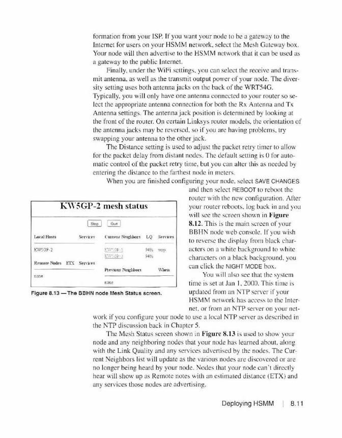
formation from your lSP. If you want your node to he a gateway to the Internet for users on your HSMM network, select the Mesh Gateway box. Your node will then advertise to the HSMM network that it can be used as a gateway to the public Internet.
Finally, under the WiFi settings. you can select the receive and transmit antenna, as well as the transmit output power or your node. The diversity setting uses both antenna jacks on the back of the WRT54G. Typically, you will only have one antenna connected to your router so select the appropriate antenna connection for both the Rx Antenna and Tx Antenna settings. The antenna jack posit ion is determined by looking at the front of the router. On certain Linksys router models. the orientation of the antenna jacks may be reversed, so if you are hav ing problems. try swapping your antenna to the other jack.
The Distance setting is used to adj ust the packet retry timer to allow for the packet delay from di stant nodes. The default setting is 0 for automatic control of the packet retry time, but you can alter this as needed by emering the distance to the farthest node in meters.
When you are fi nished configuring your node. select SAVE CHANGES
and then select REBOOT to reboot the
K\Y~GP-2 mesh status router with the new configu ration. After your router reboots. log back in and you will sec the scree n shown in Figure 8.12. Th is is the main screen of your BBHN node web console. I f you wish to reverse the display from black characters on a white background to whi te characters on a black background. you can click the NIGHT MODE box.
Lo<al Host.< Sernres C'wrenl Nel!!liboH LQ Sen i ces
KW5GP-2 :_:v~:'". 1~ F -1 94% vo1p }-7,.-,':.Gt-' -.:i 94%
R.e1no1e Nodes ITX Senite~
Pl en ot" Neiglibo1" \\l tPJ\
none none
Figure 8.13 -The BBHN node Mesh Status screen.
You will also see that the system time is set al Jan I . 2000. This time is updated from an NTP server if your HSMM network has access to the Inter-net. or from an NTP server on your net
work if you configure your node to use a local NTP server as described in the NTP discussion back in Chapter 5.
The Mesh Status screen shown in Figu re 8.13 is used to show your node and any neighboring nodes that your node has learned about, along with the Link Quality and any services advertised by the nodes. The Current Neighbors list will update as the various nodes are discovered or are no longer being heard by your node. Nodes that your node can ·t directl y hear will show up as Remote notes with an estimated distance (ETX) and any services those nodes are advertising.
Deployi ng HSMM 8.11
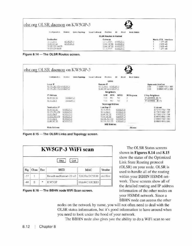
olsr.orn: OLSR daemon on KWSGP-3
De~lnation '-t ' ~ ·.::.J .: Ch",\ 5GP . \ 1
;Q":;;W;p (•<V§ GP.)1 10 100 153 144129 10 1::>3 224 80r.?8
Figure 8.14 - The OLSR Routes screen.
olsr.org OLSR daemon on KWSGP-3
OLSR Routes In Kunt l G.ileway .!...!.1.J~ .. l~ m~~ ~~ h!.i3:~'", ~
Mellie ETX lnlerfo ce 1 I ]77 wfJ
2 639 ~() 2 639 wfJ I 277 wfJ
Coui1!Jt11 ;1110 11 Route s Liuks •TopoloU)I Srn.u r G:rte w;iy Posllion All AM11t No tle SlilhJS
Local IP 10 1/6 253 170 ~ IOJZ!i~lllq~
Oesd uallon IP .l.f8..ill.jQ 10 176 ::53 170
~ ;Q \76 33 170
~ ~
M,\ ln Address
(!o,'\'15 (,0 ."1
ff'Y...SC· .:i.11
Un ks Rem ole IP I OJJ ;<.45~ l!l.H..llL5!l WW5GP·'I
Neighbors
SYM MPR MPRS Willin gness YO' S NO ' 0 3 Y~S NO ' 0
Topology Entrlu
Last ti op IP ;_Q!..Jl:\45
10 ""'' 5 ilW_llijjJ
·~ JO 176 153 170 JO 176 53 IZQ
MID Entries
Aliases
Hysteresis: U nkCost 0 00 ( I Cll1{) 732) I :El 0 Cl) (0 686.{) 497) 2 l65
2 Hop Neighbors IP ACORESS .., (1)
IP ~ESS ~"~. (1)
Un kc: of t (0 721.Q 776) 1 794 (0 77611 000) 1 197 (0 776,Q 721) I 794 (!1'97.() BBS) 2 l65 (I Cll1{) 732) I 363 (0 Bll6A) 497) 2 l65
Figure 8.15 - The OLSR Links and Topology screen.
KW5GP-3 WiFi scan
~I Chan I Enc I s~ - I MAC I Vendor_
F lil l BroadbandHamnet-20-v3 J 3262FADC5930 I Ad-Hoc
FJ8r-:- KWSGP ______ J 60A44C 68CEEO r--Figure 8.16 -The BBHN node WiFi Scan screen.
The OLSR Status screens shown in Figures 8.14 and 8.15 show the status of the Optimized Link State Routing protocol (OLSR) on your node . OLSR is used to handle all of the routing within your BBHN HSMM network. These screens show all of the detai led routing and IP address infonn ation of the other nodes on your HSMM network. Since a BBHN node can access the other
nodes on the network by name, you will not often need to deal with the OLSR status information, but it 's good information to have around when you need to look under the hood of your network.
The BBHN node also gives you the abi lity to do a WiFi scan to see
8.12 Chapter 8

L..!!..l:_J:.i.~·i~i; ..
~-!-~1_:_~.j'. Adnurmtrat10n
ful!> I Savo Chinges J I Reset Val.es J I Refrash J
DHCP Adtlrru Re_~ervittion5
H ostname IP Address MAC Address
~~~ ] 10. 111.240,45 -~Joo:~ :29· 01: 1c,S6 web - T1o.lli.2•0.•S-... fciHlc29:f7 :c6:95
C'wT~ut DHC'P Leans there are no acnve leases
Interface Type
[wAN ~jTCP vi
Name ,-vo p
web
Advertised Ser.rices
Lc'1k URL
10-F11~'.i~'L '~'~ 10 1 )r., _:[-;If !~
0 --://KWSGP·l" :~/~ ~
Po11 For'4.·:trdine Outside
Port :.AN
LAN IP Port
I· I? Acl:Ye.s • yr Figure 8.17 -The BBHN node Port Forwarding, DHCP, and Services screen.
what o ther WiFi networks your node can hear. These include both BBHN and standard WiFi networks as shown in Figure 8.16. This information wi ll be particularly useful for a node on a high point to see just how many other networks are on the same 2.4 GHz channel as your Linksys router that can cause packet delays on your BBHN HSMM network.
If you plan to run a server on your BBHN node, you will want to advertise its services on your BBHN network to the other users. To do this, go to the Setup screen and select the Port Forwarding, DHCP, and Services link. On this screen, shown in Figure 8.17, you can make DHCP reservations for your servers. A DHC P reservati on is used to assign the same address to a DHCP client based on its MAC address. This is similar to assigni ng a static IP address to the DHC P client since it will always receive the IP address information. When you make a DHCP reservation, that address is unavai lable for assignment to any o ther DHCP client.
The Advert ised Services area is where you set up what services your node will advertise to the network. Once you have made a DHCP reservation for a device. it becomes available to advertise that device's service, along with a clickablc link your network users can use to browse to that service, such as a web page.
Port Forwarding is used to map ports on your public Internet connection on the WAN port to devices on your LAN if you want those devices and services to be accessible from the public Internet.
And lastly. the Administration screen shown in Figure 8.18 is used to
Deploying HSMM 8.1 3

Node Status p.,n ;:.,rwar<hr>..2.
DHCP. and SerJ1ces
Finnware U 1>date
current version 3 1 0
Upload F111'1\ware I Browse ... J No file selected
Download Firmware - Select. f1 t:"roware vJ ( Refresh J ( Downbad J
Park;igC' M;inageinent
Upload Package I Browse ... J No file selected. ~
Download ?ackage L- Se l ecc Poc~oQ• - v JI RelTesh J [ Do..nload J
Remove Package I - Se l ect Pa c ka9e - .., J
Authorized SSH Key<
Upload Key I Browse ... J No fi le sele<"ted.
Figure 8.18 - The BBHN node Administration screen.
update the BBHN firmware on your node, install and remove packages such as the Ha111Clzat application we discussed in Chapter 5, and to set a
Secure Shell (SSH) key for your node.
Building an Outdoor Box for the Linksys WRT54G Wireless Router
Figure 8.19 -The outdoor sprinkler timer enclosure used to locate the WRT54G router outdoors, near the antenna.
One area of concern with using the Linksys WRT54G wireless router as a node on your HSMM network is that it is not designed for outdoor use. This can be problematic because we need to keep our antenna feed line as short as possible. This is usually not feasible when using the WRT54G indoors. A better solution would be to mount the router in a weatherproof outdoor box and use Power-overEthernet (PoE) to power the router from
8.14 Chapter 8

Figure 8.20 -The inside of the outdoor sprinkler timer enclosure.
the CATS data cable used Lo connect the router to the LAN side of your local HSMM node.
Using a weather resistant outdoor sprinkler timer box (Figures 8.19 and 8.20) I bought for $32 from Home Depot, I removed the Linksys router from its plastic case and mounted it onto the removable plastic shelf inside the timer box as shown in Figure 8.21. A short run of RG-8X coax is used to connect the RP-TNC connector on the antenna jack of the WRTS4G to an N-type coax bulkhead adapter used to connect to the wire mesh antenna. The CATS data cable is fed through a watertight grommet to the PoE adapter, which splits the power and data cables into two separate adapters that connect to the WRTS4G. Two large washers are used Lo close off the unused large hole in the bottom of the timer box and the build is complete. One nice feature of this particular enclosure is that it has a key lock, adding a measure of securi ty to an outdoor installation. The finished and mounted outdoor installation with a 24 dB gain wire mesh di sh antenna is shown in Figure 8.22.
Deploying HSMM I 8.15
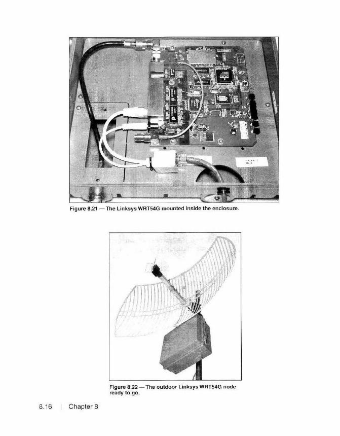
Figure 8.21 - The Linksys WRT54G mounted inside the enclosure.
8.16 Chapter 8
Figure 8.22 -The outdoor Linksys WRT54G node ready to go.

Installing BBHN/ AREDN on the Ubiquiti Wireless Router Before installing the BBHN/AREDN firmware on the Ubiquiti router,
be sure to check the BBHN and/or AREDN websites for important information regarding the Ubiquiti routers. As of early 20 16, there was an issue regarding the insta llation of the BBHN/AREDN fiimware on Ubiquiti devices using AirOS version 5.6 or newer. There is cuITently a work-around procedure posted on the www.aredn.org website to resolve this issue. The workaround requires that you downgrade the router firmware to AirOS version 5.5.
Installing the BBHN/AREDN firmware on the Ubiquiti series of wireless routers is very s imil ar to the installation process for the Linksys WRT54G routers. One of the main dilTcrcnccs is that the default IP address of the Ubiquiti web admin istratio n console is 192. 168.1.20. Another difference is that the Ubiquiti routers a rc powered using PoE. You will need to connect your worksta tio n cable to the LAN s ide of the PoE adapt-
tillblldMliHP 1411 os· 11'!!'.mDmDm m!D ~--
Timtwne: (GMl)Wo!:n~m Europt .., I
B:te\. u;:i Cont19.nt•(l(t { Oownk>ad
&1."lble S1~rtut> D~~ D ~:,3rtup 0Me
UCnl3d Cont l\"fl.11'2tlOn I 8t°""'H - I n .. He Hl•<.t @J
~ ~ ( Ru vt 10 0 (1 1Julu ] j Suwurt Info J
_l
_J
Figure 8.23 - Preparing to upload firmware to the Ubiquiti wireless router.
Deploying HSMM 8 .17

er and either set your workstation to an IP address on the firmware is beirig l.lpd.ned
This operat ion taki!s: several minVles t o com~ete · mnnwtiile 00 NOT POW ER OF F' 1he doe11ice!
[ Clos:e this window )
192.168. J .x network or set your workstation to use DHCP. Connect the PoE side to the Ethernet connector on the Ubiquiti router. To prevent damage to the Ubiquiti unit, be sure that it is mounted in the antenna assembly.
Figure 8.24 - Uploading firmware to the Ubiquiti wireless router.
After browsing to the web administration console, use the UPDATE FIRMWARE button on the SYSTEM tab to upload the BBHN or AREDN firmware from your workstation as shown in Figures 8.23 and 8.24.
Once the firmware has been uploaded, Figure 8.25 shows that the IP address of the Ubiquiti router is now at 192. 168.1.1 until you complete the configuration. Select the SETUP button and you will see the same screen (Figure 8.26) we saw when configuring the Linksys router. Select the
NOCALL-26-137-182
nu node u n.o i yd configured. Co to the setup page and ;rci your node name andpu1word.
Click Save Change .. , e\~n ifrou didn't mah-e any <ha.nus. then th.e node uill re•oot
This ~vic t c:ut ~ co nfi;.und to e1thu penn.it oz prohibit known encrypted tu.ff1e on ih RF luV: , II u up to the user to decide wlUch ~ •ppropriate b.ll'l!d on how 11 will b~ wed il'.d tlw hcerue under which it Y.ill be openttd Theff .rules vuy by country. frequ1mc:y, and intendi:!d we You il'! eru::O'UJ:a;td lo re.M .ind undusl.uid. the1e rule1 before (OU\& fu?1~r
Tlw d.evi.ce u prc·confi.gu.red Wllh no restnct10ru .u t o th! type of data bem; p~~ed Uld u CWTent ly compatible with the- LuUsY' WRr54G.seriu BBHN funrw;ue
follow thu e sl!PI if '{9U wilh to ptohl'b1t known ut:ryp titd trUfic O!\ tlu Rf WU.: Thtst uu nuc t10ru will d1upput, so copy th.em fot your nfiiruv.:e ·
I Setup y001 ?".ode :ume ill1.d p.usword &S uutructed a! the t op of this p~ 2 Afl:u :,-ou Sa.~ Cha .. n.;u illow )""OW" node to ~boot
3 Return to th.e Hod' Sta.tw p~ a.nd. navi;.a.te to Setup ,. Ad.."ll.UWha.t.on 4 Obtur. t he bbckknownenc rypllOn p a.e k~ fro m the BEHN Y."l!bnte OR
refruh the- P.a.c k~ Wt ( node mw t be co nnected to th.e u1ler11!t) 5 l1ut.ill the blockknowr~nc1ypt10n pM:k~ by uplo.ding it o r cl-.oosin;
11 from tl:I.'! p.ck~ drop· down Wt 6 W.ut until the- p M:k~ uuta.lls W Hlttt ttbooot ~nod@
de fa u1 t ga tewa.y none
firmW'U1! ~nion 3 I 0 configuration not se t
• Thu JU\ 1 1970 i ystem time 00 16:42 UTC
uptim.e 16 min load average 0.08, 0 0 5, 0 .05
!Wh = 3500 KB free qtace ltmp .. 14516 KB
memory• 9 156 KB
Figure 8.25 - The initial configuration screen for BBHN on the Ubiquiti wireless router.
8.18 Chapter 8
SETUP option on this screen and you will see the Basic Setup screen (Figure 8.27). The Basic Setup screen on the Ubiquiti router is virtually the same as for the Link-sys router with a few exceptions.
The Ubiquiti router shown is the 5 GHz AirGrid M5HP. On the WiFi set-tings for the 5 GHz band, you have the option to select the Channel and Channel Width. As you deploy additional devices for this network configuration, remember that they will all need to have the same Channel and Bandwidth settings. Everything else in the Basic Setup is the same as for the Linksys router.
When you mount your BBHN or AREDN antenna, remember that the recommended antenna polarization for BBHN/ AREDN is vertical polarization as shown in Figure 8.22. All nodes must use the same antenna polarization for optimal performance between your wireless network links. Also, since the Ubiquiti routers typically only have a single Ethernet port, you will need a switch to connect the LAN side of the Ubiquiti PoE adapter and the rest of your local HSMM network.
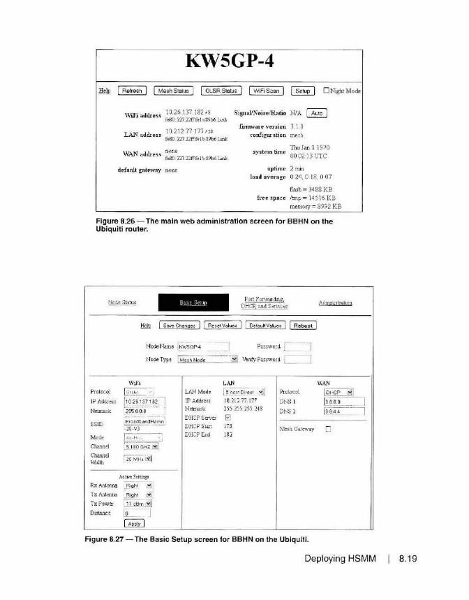
KWSGP-4 Mesh Status J OLSRSto.tus [ W1F1Scan [ Setup J 0 Night Mode
\Vi.Fi address 10.26.1 37.182 18 fe80 227 22fff•l •89b6 Unl:
Signal/Noise/Ratio NIA ~
LAN address 10.212 77 177 11.9 fe80 :227 22£ff<I b 89b6 Unl:
\VAN address none fe80 :227 22fffe l b .89b6 Unl:
default gateway none
firmware version 3_ LO con.figuration mesh
Thu Jan I 1970 system time 00 02 13 UTC
uptime 2 mm load average 0. 24, 0 18. 0 07
flash= 3488 KB free space /tmp= 14516 KB
memory = 8992 K B
Figure 8.26 - The main web administration screen for BBHN on the Ubiquiti router.
Port Forwanhng. DHCP and Services
!:kill l Save Chon~es J l Reset Values J [ Defaull Values J I Reboot J
Node Name ~G_P4 Password
Node Type j Mesh N~~-~·---~:~=~; Venfy Password L___ ·-J
Protocol
IP Address
Netmask
SSID
Mode
Channel
Channel Width
Wifi
! s 1 . ~ 1 1( · ~
{i o2s,.1 Jl18?] m .o.o.o ··· · J
BroadbandHamn TQ":V3"-
l <d-H<... 'J 15180 G!:fZ.iiJ
[20MHz t~iJ
ActIVeSetl~
Rx Antenna _f3ight ... ~ Tx Ante:r.na ~t ~]
Tx Power [ 17 dB~ Distance L - -1
I Apply I
LAN LAN Mode [ ~:~s t ()irect _._":J]
IP Address 10. 212.77. 177 Netmask 255.255. 255. 248
DHCP Server 0 DHCP Start 178 DHCP End 182
Protocol
DNS l
DNS2
Mesh Gateway
Figure 8.27 - The Basic Setup screen for BBHN on the Ubiquiti.
Adrru.Justration
WAN
~ [ease _____ 1
[~8)~4 =1
D
Deploying HSMM 8.19

Deploying HamWAN
_!.._:'_,•nF~w
il¢ 1<•"1)1'~
\:,; l yll• ... _
- "'' ~;.·<f,, .. ~~ol• •
!!._~~~~!'•I ~Mtu P:OUTEP:
= Hi4•P•uw.,.ff ~. s.,n •I
'!" S•~.~d! ... ITMS1't1t•I ...J O•Jlg• '>Un . ·· '
QMo•ul
• wi..a.o. ~o •• ,h
~::::Ur -1
'1l/~((Q
Deploying a Ham WAN node is a bit more complicated than a BBHN/ AREDN node. You will need to have an accessible cell site for your node to connect to since the Ham WAN clients cannot relay through each other as with the BBHN/AREDN implementation. At present, there are several methods used to configure the Ham WAN client and cell site nodes using the MikroTik Metal SSHPN and the next generation RB912UAG radio modems. I recommend vis iting the www.hamwan.org website for the current recommended configuration instructions and other information for building and configuring the cell sites and the clients. The Memphis Ham WAN group (www.memhamwan.org) has created a set of executable scripts that do all of the client node configuration for their network client nodes automatically.
The Ham WAN implementation does not require custom firmware to operate. Instead it uses the standard Router0Sv6 software that comes with the MikroTik router. Figures 8.28 and 8.29 show a Ham WAN node after it has been configured for the Memphis Ham WAN network using the installation scripts. Be sure that the MikroTik router is connected to an antenna any time it is powered on to prevent damage.
Unlike the BBHN/AREDN networks, HamWAN networks use horizontal antenna polarization. Be sure to use the correct antenna polarization for your Ham WAN network as shown in Figure 8.30.
Regardless of which technology you use. once you have your node up
Info
urliJnil~~'IJ>'J
""""~ v_ lblu/ 1
J.900 ;
DM(jl\-~ 6 10oQ,o.10cw-J
l'IAJ 8
Drld11e A\ll ... N Peth 0
Confi9urat1on
Local Ne t wort;
Bridge
System
Figure 8.28 - The MikroTik Metal S5HPN Quick Setup screen for the Memphis HamWAN network.
8.20 Chapter 8

4: Quick Se:t
.!.. CAPsMAN 11 Interfacu II N streme Dual I Acct~~ Lls~-- l! · Re.gittr~tion I Conn.ct List II S•c.urit:y Pl'ofllu II Ch.inntol s l f-im_ln_«_rl'_•<_••----l ( Add N•w I ~PPP
3 ite ms
~ IP list N.ame
EN~n1ion
Ch•nnel
( / MPLS • ; ;; Ce ll s 1t4!! S r ;odi;,te th is .lt 0 degrees (north)
~' .. 0 pe.n.F1 ow .J.Jtl Ha.mWAN S~cto:ir 1 ·L O :S920.000 I 0 .000 5GHi-onl't dis abled
C Routing
W System 5"90 0.000 I 0.000 5GHi-only d1ubled
• Que.ues
a Files .J.2.1 Soiii;to,3-10 5880.0 00 10 .000 5GH2-only diH ble d
Ll Lo9
§.R-1di1.1s
Figure 8.29 - The MikroTik Metal S5HPN Radio Channel Configuration for the Memphis HamWAN network.
and running, it' s time to test the connectivity between the nodes on your network. You can use the PING and TRACEROUTE commands
to verify that you can communicate with the various nodes on your network and see the route that your data packets are using to get to their destination.
At this point, you have the infrastructure built. All you need to do now is add some servers and applicati ons and your HSMM network is ready to go. As you move forward, you ' ll fin d that having a high speed network independent from the public Internet can prove invaluable for provid ing communications during pub I ic service events and disaste r support. You'll also tind that it 's a fun way to experiment w ith high speed digita l communications. T here is v irtually no limit to the Inte rne t-based applications you can add to your ne twork, and fi guring o ut new v.1ays to do th ings using yo ur HSMM network is a g reat way to enjoy th is new and rapidly expanding area of Amateur Radio communications.
Figure 8.30 -A horizontally polarized wire mesh antenna used for HamWAN.
Deploying HSMM 8.21

References
8.22 Chapter 8
airlink.ubnt.com www.aredn.org blog.gearz.net/2007/09/rf-propagation-modeling-with-splat-for.html www.broadband-hamnet.org www.cplus.org/rmw/rmonline.html dds.cr.usgs.gov/srtm data.geocomm.com/dem www.hamwan.org www.memhamwan.org www.qsl.net/kd2bd/splat.html www.wikipedia.org

Chapter 9
The Future of HSMM
The technology used in Amateur Radio HSMM networks is in a constant state of change. All of lhe HSMM development groups are not content to sit idle with what they have done, but instead continue to push forward and improve upon what they have accomplished. So where can we expect Amateur Radio HSMM to be in just a few more years?
As good as it is for a simple, easy to deploy and use HSMM network, the Linksys WRT54G used with the shared 2.4 GHz spectrum just isn't conducive for growth in terms of network throughput and enhanced functionality. The memory limitations of the Linksys router are becoming a limiting factor in enhancements Rnd improvements that can be made. At some point, further development will probably end on the Linksys routers, but they will remain a viable tool for si mple and easy to deploy HSMM networks.
The Ubiquiti routers offer the greatest flexibility for the future development of the BBHN and AREDN technologies. The upcoming 3. 15. 1.0 version of the AREDN firmware will allow the use of Part 97-only channels in the 900 MHz, 2.4 GHz, 3.4 GHz, and 5.8 GHz bands. While the 900 MHz band allocation is relatively small and can have a high noise floor from commercial users in large cities, it can help solve those link issues with regard to trees and other small obstructions in the path that would reflect the higher frequency signals.
In the futu re, I expect that we can see all of the HSMM technologies moving to the Part 97-only po11ions of the various bands to reduce the noi se fl oor and allow wider bandwidths, which in turn will allow for
The Future of HSMM 9.1

9.2 Chapter 9
higher overall data throughput and more reliable networks. On the Ham WAN side, thei r development group is working with
900 MHz as well. and experimenting on replacing the Open Shortest Path First (OSPF) routing protocol used in their networks with a routing method that has the ability to dynamically make routing decisions on-the-fly based on the quality of the link and other techniques to enhance communication with mobile nodes. Sec? I told you these development guys are always thinking up new stuff all the time. Adding a mobile HSMM node to the mix can bring a whole new meaning to portable networking and what it can do for the public service communications aspect of HSMM networking.
Ham WAN is also experimenting with what they call a "mini Point of Presence" (mini-PoP) that uses a single omnidirectional antenna in place of the standard three 120-degree sector antennas at a cell site. They're also investigating moving to a dual polarity antenna configuration for the cell si tes to allow for improved client coverage.
On the application side of things, I would expect to see greater use of the Raspberry Pi boards. both as application servers and as HSMM nodes. Projects such as the HSMM-PI project and others will bring new applications and features to our HSMM networks. With its small size and power requirements, the Raspberry Pi is ideally suited to perfom1 the role of an application server in portabl e public service events and disaster support.
Are BBHN/AREDN and Ham WAN the only HSMM technologies we'll see moving forward '/ Probably not. The world of Amateur Radio HSMM networks is in a constant slate of flux and there is little doubt that we will see other development groups join in on the fun. In the end, I think you may see a technology emerge that builds upon the existing technologies, combining the best of both worlds. It could allow for the high throughput of a Ham WAN network with the ability of a BBHN/AREDN node to link through another client node for those people like me who don't have a clear line-o f-sight path to an existing Ham WAN cell site.
In any case. the world of A111ateur Radio HSMM networks is a rapidly growing area for ha111s to experiment and explore. It provides a unique playground for hams to experiment with high speed digital communications and to build out robust and resilient data networks linking hams together worldwide. These are fun ti111es and I, for one, look forward to seeing where this all goes from here.

Appendix
Glossary of Terms
AllStar - An Asterisk-based voice-over-IP system used to link with repeaters over the Internet; similar to EchoLink.
AMPRnet (Amateur Packet Radio Network)- The organization that manages the allocation of the IP address block of 44.0.0.0/8 reserved for use by radio amateurs.
Antenna polarization - The physical orientation of an antenna in relation to the electromagnetic orientation of an RF signal.
APRS (Automatic Packet Reporting System) - A system to provide real-time track.ing information using packet radio, developed by Bob Bruninga, WB4APR.
AREDN (Amateur Radio Emergency Data Network) - An Amateur Radio HSMM development group.
ARP (Address Resolution Protocol) - A TCP/IP protocol used to map an IP address to a MAC address.
ATA (Analog Telephone Adapter) - Used to connect a standard analog phone to a VoIP system.
BBHN (Broadband-Hamnet) - An Amateur Radio HSMM development group.
BGP (Border Gateway Protocol) - The primary routing protocol used in the public Internet to exchange routing in formation between networks.
Blacklist - A list used by a content filter lo block access based on crite1ia in the li st (websites, domains, URLs, and so o n. ).
CA (Certificate Authority) - An entity that issues digital certificates.
CAT5/CAT6 - A data cable based on the ANSl/TlA/ElA-568-A and TIA/EIA-568-B standards that uses four pairs of 20 or 24 AWG twisted pair copper wires, usually unshielded, and most commonly having an 8-pin modular RJ-45 connector at each end.
Glossary
2 I Appendix
Cell Site - A central communications node used in a Ham WAN network to link client nodes to the network.
Certificate - An electronic document used to verify the identity of the sender.
CIDR (Classless Inter-Domain Routing) - A method for allocating IP addresses and the routing ofTCP/lP based on the subnet mask and not on the strict definition of the IP address class range.
ClearOS - An open source CentOS-based Linux distribution designed for network-based applications.
Client node - The end user in a Ham WAN network.
Clip Bucket - An application to provide video and photo sharing services on a network.
CMS (Crisis Management System) - An application used by emergency response organizations to coordinate and manage their operations.
Codec - A method used to encode and decode a digital data stream, often used in video and audio applications.
Content filter - A device or application used to control access to webbased content based on blacklists and other criteria.
CSMA (Carrier Sense Multiple Access) - A media access and transmission method that allows multiple devices to use the same transmission medium by transmitting only when not being used by another node.
Da11sGuardia11 - A Linux-based application used to provide content filtering.
dBm - A measure of power in re lation to one milliwatt.
Default gateway - T he node on a network used to forward data to other networks.
Default route - The route used to forward data when no specific route is known for the destination IP address.
DHCP (Dynamic Host Configuration Protocol) - A protocol used to automatically provide a host with its IP address and other related configuration information.
DMZ (Demilitarized Zone) - A subnet that resides between the public Internet and the Local Area Network used to allow access to some network resources while providing a measure of protection for the LAN from external access.
DNS (Domain Name System) - An Internet naming system used to translate between IP addresses and Internet Domain Names.

D-Star (Digital Smart Technologies for Amateur Radio) - A digital voice and data protocol for Amateur Radio.
Dynamic routes - An IP route learned from a routing protocol that can automatically change based on the cu1Tent network topology.
EchoLink - A web-based application used to link with repeaters and other Amateur Radio systems using the public Internet.
Endpoint manager - An application used in voice-over- IP (VoIP) systems to automatically provision and configure IP phones.
FCC Part 15 - The portion of the FCC rules that pertai n to unlicensed, low power transmitters such as home wireless dev ices.
FCC Part 97 - The port ion of the FCC rules that pertain to Amateur Radio and the conduct of Amateur Radio operators.
FileZilla - A File Transfer Protocol (FTP) client application used to transfer files with an FTP server.
FirewalJ - A network securi ty device o r application that monitors and controls the incoming and outgoing network traffic based on predetermined security rules.
Firmware - Computer soft ware that is held in non-volatile memory such as ROM, EPROM, or fl ash memory.
FQDN (Fully Qualified Domain Name) - The complete Internet domain name for a specific computer, or host, that contains the host and domain name.
FreePBX - An open source Limn -based voice-over-IP (VoIP) system based on Asterisk.
Fresnel zones - series of concentric ellipsoidal regions of alternating double strength and half strength volumes of a wave's propagation, caused by a wave following multiple paths as it passes by an object and is partially refracted by it, resulting in constructive and destructive interference as the different length paths go in and out of phase.
FTP (File Transfer Protocol) - A TCP/IP protocol used to transfer tiles between hosts.
FXO (Foreign Office Exchange)- A card or a network attached interface used to connect a VoIP syste m to the regular telephone system.
FXS (Foreign Exchange Station) - A card or network attached interface used to connect a standard analog telephone to a Vol P server.
HamChat - An Instant Messaging application that runs on the BBHN and AREDN nodes.
Ham WAN - An Amateur Radio HSMM development group.
Glossary 3
4 I Appe ndix
HSMM (High Speed Multimedia) - multiple forms of information such as voice, video, data, and text operating over a high speed data network.
Hypervisor - Computer sort ware. fi rmware o r hardware that creates and runs virtual machines.
IAX (Inter-Asterisk Exchange) - The communication protocol used to link multiple Asterisk systems together.
ICMP (Internet Control Message Protocol) - A TCP/IP protocol used by network devices to send error messages and relay query messages.
IDS (Intrusion Detection System) - A dev ice or software application that monitors the network for malic ious activities or policy violations.
IEEE 802.1 Q - The IEEE networking standm·d that supports virtual LANs (VLANs) on an Ethernet network using a system of VLAN tagging for Ethernet frames.
IMAP (Internet Message Access Protocol) - A TCP/IP pro tocol used by e-mail clients to retrieve e-mail messages from a mail server.
IP address - A binary number often represented in dotted decimal notation (such as 192. 168.1. l ) that is assigned to each device on a computer network us ing TCP/IP for communication.
IPS (Intrusion Prevention System) - A network device or application used in conjunction with an Intrus ion Detection System (IDS) to actively prevent and/or block detected intrusions.
IPsec VPN - A Virtual Pri vate Network (VPN) communication protocol used for encrypted commu nication between hosts.
I Pv4 - A 32-bit IP addressing and routing standard prov id ing 4.294,967,296 (2" ) unique IP addresses.
I Pv6 - A 128-bit addressing and rout ing standard scheme providing 3.4 x 1 03~ (3.4 undecill ion ) unique IP addresses.
LAN (Local Arca Network) - Local segment of an Ethernet network.
LDAP (Lightweight Directory Access Protocol) - An open TCP/IP protocol for accessing and mai ntaining d istributed directory information services over a network.
Linksys WRT54G - A wire less rou ter manufactured by Linksys/Cisco often used in BBHN HSMM networks.
MAC address - Media Access Control address, a 48-bit hardware level address used to identify hosts on an Ethernet network.
Mesh topology - A network topology where all of the nodes in the network can communicate with all other nodes in the network, either directly or by relaying the data through intermediary nodes.
MikroTik - A Latvian manufac turer of wire less equi pment. MikroTik equi pment is often used in a Ham WAN HSMM network.
MIMO (Multiple Input Multiple Output) - A wireless technology where multiple spacial streams of data on multiple channels are used to increase data throughput.
Mini-PoP (mini Point of Presence) - A scaled-down version of a Ham WAN cell site using a si ng le omnidi rectional antenna instead of the three 120-degree sector antennas in a typical cell site.
Nagios - An open source application that provides monitoring and alerting for servers, switches, applications and services.
NAT (Network Address Translation) - An IP addressing method used to conserve public lP addresses by mapping public IP addresses to private IP addresses using port forwarding.
Nslookup - A utility used to test and veri fy DNS resol ution.
NTP (Network Time Protocol) - A TCP/l P protocol for clock synchronization between network devices.
OLS R (Optimized Link State Routing Protocol) - A routing protocol similar to OSPF that is optimi zed for ad-hoc networks such as the BBHN and AREDN networks.
Openfire - A real-time collaboration (RTC) application used for instant messaging and file/image transfer.
Open source - Often re fers to a computer program in which the source code is avai lable to the general public for use and/or modification from its orig inal design. Many open source appl icat ions are available free of charge.
OpenLDAP - A free open source implementation of the Lightweight Directory Access Protocol.
Open VPN - An open source application for secure point-to-point or siteto-site VPN connections.
OS I model - Open Systems Interconnect networking model, a conceptual 7 layer model for describing network communication.
OSPF (Open Shortest Path First) -A LAN routing protocol used to dynamically determine the optimal route to a destination.
Path profile - A graphic representation of the physical features of a propagation path showing the terrai n, incl uding trees, buildings, and other features that may obstruct the radio signal.
Ping (Packet InterNet Groper) - A utility that uses the ICM P protocol to test the reachability of a host and to measure the round-trip time for messages.
Glossary 5
6 Appendix
PoE (Power-over-Ethernet) - A system that passes electrical power along with data on an Ethernet cable.
POP3 (Post Office Protocol 3) - A TCP/IP protocol used by e-mail clients to retrieve e-mail from a server.
Port forwarding - Used in conjunction with NAT to redirect data from one IP address and port number combination to another. Mainly used to map public IP addresses to private IP addresses on a LAN.
PPTP (Point-To-Point VPN) - A VPN protocol used to create a secure connection between a client and a remote host.
PRI - Primary Rate Interface (PRI) is a standard telecommunications interface used for voice and data, based on the T 1IE1 data circuit.
Private IP address - An IP address in the private IP address range that is not routable over the public Internet. Often used in conjunction with NAT to conserve public IP addresses and provide a measure of isolation from the public Internet.
PRTG (Paessler Router Traffic Grapher) - A network monitoring and bandwidth usage application.
Public IP address - A globally unique IP address that can be directly accessed from the public Internet.
Public-Private Key cryptology - An encryption method where anyone can encrypt messages using the public key, but only the holder of the private key can decrypt the message.
QoS (Quality of Service) - A method used to manage and allocate bandwidth usage based on the prioritizing of network traffic.
RAID (Redundant Array of Independent Disks) - A disk controller technology that combines multiple physical disk drives into a single logical unit for the purposes of data redundancy, perfom1ance improvement, or both.
Raspberry Pi - A small single-board computer that typically runs the Linux operating system and incorporates onboard video, audio, and Ethernet interfaces.
RDP (Remote Desktop Protocol) - A proprietary Microsoft protocol used to remotely connect to a Windows workstation.
RemoteShack - Hardware and software used to connect an Amateur Radio station to the Internet for remote operation.
RIP (Routing Information Protocol) - A routing protocol used to dynamically determine a TCP/IP route to a destination network.
Router - A network device that forwards data packets between computer networks.
Routing loop - A condition where a routing en-or exists that causes the data packers to go back and forth between routers and never reaching the intended destination.
RP-TNC connector - A reverse-polarity TNC connector commonly used in wireless devices such as the Linksys WRT54G.
SIP (Session Initiation Protocol) - A communications pro toco l for signaling and controlling multimedia communication sessions, most commonly in a voice-over-IP telephony system.
SIP trunks - Uses the SIP protocol to link a VoIP system wi th an Internet telephone service provider who provides a gateway to standard telephone networks without the need for standard telephone lines.
SMTP (Simple Mail Transfer Protocol) - A TCP/IP protocol used for e-mail transmi ssion.
SNMP (Simple Network Monitoring Protocol) - A TCP/IP protocol used to remotely moni tor and manage network devices.
Softphone - An application used to emulate a VoIP phone.
Snort - An open source Intrusion Detection System.
SnortSam - An open source extension to Sn011 to implement an Intrusion Prevention System.
Spark - An Instant Messaging client based on the Internet Relay Chat (IRC) protocol.
SPLAT! - A command line-based RF signal propagation, path loss, and terrain analysis tool.
Spread spectrum - A fom1 of wireless communications in which the frequency of the transmitted signal is deliberately varied.
Squid - An open source caching and web proxy application.
SSH (Secure Shell) - A TCP/IP protocol to allow secure remote command li ne access to a host.
SSIO (Service Set Identifier) - A 32 octet number, often depicted as a sequence of characters that uniquely names a wire less LAN.
SSL (Secure Sockets Layer protocol) - A TCP/ IP protocol often used to estab lish an encrypted link between a web server and a browser.
Star topology - Also known as "Hub and Spoke:· The cl ient nodes communicate directl y with a central site .
S tatic routes - A manually-configured routing entry that is not altered by dynamic routes di scovered by a routing protocol.
STP (Spanning Tree Protocol) - A network protocol used to prevent switch loops while still allowing for redundant network paths.
G lossary 7

8 I Appendix
STUN (Session Traversal Utilities fo r NAT) - Used to permit NAT traversal for applications using real-time voice. video, messaging, and other in teractive IP communication.
Subnet mask - Used to define the network and host addresses in an IPv4 network.
Switch - A multiport network device that uses hardware MAC addresses to process and forward frames at the data link layer.
Switch loop - An error condition that occurs when there is more than one Layer 2 path between two hosts on a LAN.
TCP - Part of the TCP/IP protocol that provides reliable, ordered, and error-checked de livery of data packets .
TCP/IP (Transmission Control Protocol/Internet Protocol) - One of the most common networking protocols in use.
TOMA (Time Division Multiple Access) -Allows mul tiple users to share the same frequency channel by dividing the signal into different time slots for user access.
TeamSpeak - A proprietary voice-over-IP (VoIP) application that allows multiple users to speak on a chat channel.
Traceroute - A utili ty for displaying the routing path and measuring the transit delays of packets across an IP network.
TTL (Time to Live) - A method that limits the lifespan of data, often specified as a "hop count ," on a network. Once the prescribed lifespan has been exceeded, data is d iscarded.
Ubiquiti - A manufacturer of wire less equipment often used in the BBHN and AREDN HSMM networks.
UDP (User Data Protocol) - A connectionless TCP/IP protocol for fast transmission of data (usually streaming multimedia data) with no guarantee of delivery. o rdering, or duplicate protection.
UPS (Uninterru ptible Power Supply) - Provides near-instantaneous protection from input power interruptions, often using an ac to de to ac power inverter with balleries to supply power during brief interruptions.
Virtualization - The creation of a vi rtual (rather than physical) version of a network device such as a server.
Virtual machine - An emul ati on of a physical computer system in software.
VLAN (Virtual LAN) - Used to create separate local area network (LAN) segments that are isolated from each other but use the same physical transmission media.

VLSM (Variable Length Subnet Mask) - A more efficient method of dividing an IP subnet into a group of smaller subnets to conserve IP address usage.
VoIP (Voice-over-IP) - Provides te lephony and multimedia services over an IP network.
VPN (Virtual Private Network) - A secure private connection between two hosts using the public Internet.
WAN (Wide Area Network) - A computer network that extends over a large geographical distance.
Webmifl - A web-based system configuration tool for Linux systems.
Web server - A server used to store, process and de liver web pages to clients, usually via the Hypertext Transfer Protocol (HTTP) and the Hyper Text Transfer Protocol Secure (HTTPS) IP protocol s.
WEP (Wired Equivalent Privacy) - An encryption and security method used in IEEE 802. 1 I wireless networks.
Winlink 2000 - A worldwide radio messaging system that mixes Internet technology and Amateur Radio RF technologies.
Wireshark - An open source application used for network troubleshooting and packet analysis.
WPA (Wi-Fi Protected Access)- An encryption and securi ty method used in IEEE 802. 1 I wire less networks.
Zabbix - An open source application for monitoring and tracking the status of various network services, servers, and other network hardware.
Glossary I 9

Notes

Notes

Notes

- ----
Notes

Notes

Notes

Index Note: The letters " ff" after a page number indicate coverage of
the indexed topic on succeeding pages.
802 .1 Q: ..... ....... ......... .... ........ ......... ........ .... ........ ............. .. 2.8, 4.33ff
A Ad-Hoc Network: .......... ... ............................................................ 1.4 Adaptive Rate Selection: ................................................. ......... ... 2.3 Address Resolution Protocol (ARP): .. ....... ......... ..... ......... 2.2, 4.21 ff Advanced Research Project Agency Network (ARPANET): ........ 4.1 All Star: ........... .... .. ... .. ............................................... .................. 5.87 Amateur Packet Radio Network (AMPRnet): ........................ 1.9, 4 .2 Amateur Radio Emergency Data Network (AREDN): ........ 1.4ff, 2.5,
2.8ff, 3.1ff, 4.26, 5.24ff, 6.3, 8.1 ff, 8.17ff, 9.1ff Analog Telephone Adapter (ATA): .... ....... ...... ............... .... ..... .... ... 5.3 Angel Network Monitor: ...................... .................... .......... ........ ... 7.6 Antenna Feed Line: ........... ...................................... ............. ... .... 3.9 Antenna Polarization: ......... ........ ..................................... .......... 3.9ff Antennas: .... ............ ....... .. .............. .. ................. ..... ................. .. 3.9ff Asterisk VoIP: ............ ..... ..................... .................................... .. 5.2ff Asymmetrical Routing: ............................................................... 4.25
B Border Gateway Routing Protocol (BGP): .......... .. ................... 4.24ff Broadband-Hamnet (BBHN): ........ 1.4ff, 2.5ff, 3.1 ff, 4.26, 5.24ff, 6.3,
8.1ff, 8.5ff, 8.17tf, 9.1tf
c Carrier Sense Multiple Access (CSMA): ............... ... .................. 2.9ff Category 5/6 Data Cable: ................... ..................................... .. 3.6ff CentOS: ........... ..... .......................... 5.4, 5.34, 5.55, 5.59, 5.84, 6.17 Certificate Authority: .... ....... .... ..................................... ... .... ..... 2.1 Off Certificates (dig ital): ......... ............. ... .................. ..... ... 2.10, 5.63, 6.4 Classless Inter-Domain Routing (CIDR): ........ .. ... .... ................ 4.17ff Clear Foundation: ....... .. ....... ... ......... .... ...................................... 5.33 ClearOS: ................ .. ... ... ... ................. ... ................ ......... . 5.33ff, 6.4ff
Index I 1

2 I Index
ClipBucket: ............................ ... ............... .. ...... ... ...... ... ..... 5.77, 5.84 Codecs: ...... ..... .. .. ... ..... ..... .... .. ........ ... ...... .......... .. ........ .............. 5.23 Content Filter: .. .. ..................... ..... .. ........ ................ ....... .. 5.34, 6.12ff Counterpath X-Lite Softphone Application: .......... ..... ......... ...... 5.22ff
D DansGuardian Content Filter: .... .. ... ..................... .. ..... ............. 6. 12ff dBm: .. ..... ... ..... ................. .... .. ... .................. .... ....... ...................... 3.5 Direct Sequence Spread Spectrum (DSSS) Modulation: ............ 2.3 Domain Name System (DNS): ......... ... 2.5ff, 4.31ff, 4.38, 5.34, 5.80ff Dynamic Host Configuration Protocol (DHCP): ........... ... . 2.6, 4.29ff,
5.34, 5.79ff
E Echolink: .. ... ....... ........ ... .. ... .. .... .......................... ... .. .. ................. 5.87 Encryption: ..................................... ........ .......... ...... .... 1.4, 2.4ff, 6.2ff
WEP: .. ............. .... ... ...................... ........ .. ............. ..... ............. 2.1 WPA: ........ ......... ...... .. ... ... ...... ... ... ......... ... ... .............. .... ...... .. .. 2.1
Endpoint Manager: .... .... ..... ... ... ...... .. .. ..... .................... ..... ...... ... 5.7ff
F FCC Part 15 Rules: ...... .... ... ... .... .... ................... ... ............. . 1.3, 2.1ff FCC Part 97 Rules: ...... ................ .... ....... .... 1.3, 2.1 , 2.3ff, 5.1, 6.1 ff File Transfer Protocol (FTP): ...... ................................ .... 5.34, 5.77ff FileZilla: ... ... .................................... ......................... ................ 5. 77ff Firewall: ................... ..... .... .... .. .... ....... ... ...... .. .... .............. 5.34ff, 6.4ff Foreign Exchange Station (FXS): ..... ..... .. ... ... .. .. ... .................... ... 5.3 Foreign Office Exchange (FXO): .................................. ...... ......... 5.3 FreePBX: ............ .. ... .. .... ... ... ....... .... ............................ .... ........... 5.4ff Fresnel Zone: ....... .. ............. ................................. ... ... ........ ...... ... 8.4
G Grandstream IP Phones: ........ ............. ... .... ... ..... .. ... .... . 5.12ff, 5.1 Bff
H HamChat: ..... ..... .... ....... ......................... .. ... ................... .... ...... 5.24ff HamWAN: ........ .. ........ ... ...... .................. 1.4ff, 2.5, 2.9, 6.3ff, 8.2, 9.2
Cell Site: ... .. .. ...... .. ... ... ....... ....... ............ ..... .. ...... ........... 1.6, 2.9ff Client Node: ... ........ ..... ... .... ....... ........ ................... ....... ... ...... 2.9ff Deploying: ........... ... ............................... .. ... ... ... ...... ... ......... 8.20ff
Hidden Node: ...... ... ....... .. .. .. ... ....... .. ... ...... .. .. .. .. ... .. .. ...... ...... ... .. .. .. 1 .5 High Speed Multimedia: ... ... ........................ ... .... .. .. ................... 1.1ff

HSMM Frequencies: ....................................... .... ........... ...... .... .. 1.6ff Hub and Spoke Topology: .. ........ ................. ............................... 1.5ff Hyperlink Technologies: ..... ................ ................... ... .............. ... 3.11 ff
IEEE 802.11: ........................... ............. ........... .. .. ............. ..... 1.4, 2.2 802.11a: .... ................. ... .... ....... .... .................... ... .......... ... ...... 2.4 802.11 ac: ........ .................... .................................... ......... ...... 2.4 802.11b: ....................... ... ....... .............................. ... ........ 2.3, 3.3 802.11 g: ....... ........ ........ .................................... .... ........... 2.3, 3.3 802.11n: ......................... ... .. .......................... ....................... 2.3ff
Instant Messaging: ......... .... .... ... .... ..... ......... ....................... ..... 5.24ff Inter-Asterisk Exchange (IAX): ..... ................ ........................ ....... 5.3 Internet Assigned Numbers Association (IANA): ..... .... ........... ..... 4.2 Internet Control Message Protocol (ICMP): .. .................... .... ... .. 4.35 Internet Corporation for Assigned Names
and Numbers (ICANN): ......................... ... ........ .... ...... ... .... .... 4.32 Internet Engineering Task Force (IETF): ... ............... ........... 4 .2, 4.28
RFC 1149: .... .. .. ................. ................ .................. .......... .. .. .... 4.7 RFC 1518: .......................... ................. ... ... .. .... .... ................ 4.17 RFC 1519: .... ...................... ................ ..... ..... .. ..... .............. .. 4.17 RFC 1631 : ................ ........... ..................... ..... ...... ... ...... ....... 4.28 RFC 1878: ....... .. ...... ..... .... ............ ..... .......... ...... ................ 4 .16ff RFC 2460: ....... ............. ............... ..... ....... .............................. 4.2 RFC 2474: ................... ....... ......................... .... .. .. ....... ........... 4.4 RFC 2549: ...... ....................................... ........ ..... ..... ............ .. 4.7 RFC 3168: .. .. ...... ..... .. .................. ................. ................. ........ 4.4
Internet Message Access Protocol (IMAP): ......... ..... ................. 5.73 Intrusion Detection System (IDS): .... ... .. .................................... 6.8ff Intrusion Prevention System (IPS): ........ .... ............... .. .... ........ .. 6.8ff
L Lightweight Directory Access Protocol (LDAP): .. ...... ................. 5.34
OpenLDAP: ........ .. ....... .... .... ....... ...... .................. ... ............ .. 5.62 Linksys WRT54G: .. ... .... ........ ............. ... 1.2, 1.7, 2.5ff, 3.1ff, 8.1 , 9.1
Firmware: ...... ....... ..... .... .. .. ................. ... ... ............ ....... ......... 8.5ff LAN Ports: ...... ..... ..... ....... .... .... ................. .. .. ....... .... .... ....... . 2.6ff Outdoor Box: .. .. ......................... ....................... .......... 3.5, 8.14ff WAN Port: ................... .......... .. ...... ......................................... 2.7
Linux: .. ..... 3.4, 4 .7, 4.35, 4.37, 5.2ff, 5.17, 5.27, 5.32ff, 5.52ff, 5.73, 5.77, 5.84ff, 5.89ff, 5.90, 6.4ff, 6.12, 6.17, 7.3, 7.5ff, 8.2ff
Index I 3
M Magliacane, John KD2BD: ... ..... ..... ... .......... .. .............. ...... .......... 8.4 Magnuski , Dr. Hank KA6M: .... .... .... .................. .............. ..... . 1.9, 4 .2 McMellen, John KC0FLR: ........ ...................... ...... ........................ 8.4 Media Access Control (MAC) Address: .. ....... 2.1ff, 4 .1 Off, 4 .20ff, 6.3 Mesh Network: ........ ..... ................................ ......... ............... ...... .. 1.4 Microsoft Hyper-V: .. .. .. .... ..... ...... .. ..... .............. ..... ................. ....... 7.5 Mikro Tik: ........ ........ .... ............... ....... .......... 1.2, 1. 7, 2.10, 3. ?ff, 8.20 Modulation and Coding (MCS) Index: ............ .. ................. ....... .. . 3.8 Multiple Input Multiple Output (MIMO): .... ........................... 2.3ff, 3.8
N Nagios: ..... ........................ ...... ...... ........ .. ... ..... .. .............. .... ... ...... 7.6 Network Address Translation (NAT): .......... ............. ... .......... 2.7, 4.2,
4.14, 4.27ff, 5.23ff, 5.34 Network Time Protocol (NTP): ........ .. ......................... ..... 5.1 ?ff, 5.83 Network Topology: .......... ... .. ..... .. ..... ... ......... .. .. .... .. ......... ..... .. .... 1.4ff Nslookup: ................ .. .... ...... ... ..... ............. .. .................... ..... ....... 4.38
0 Open Shortest Path First (OSPF) Protocol: ...... ... ....... .... 4.10, 4.24ff Open Systems Interconnection (OSI) Networking Model: .. 2.2, 4.6ff Openfire Messaging System: ................. ................................. 5.27ff Optimized Link State Routing (OLSR) Protocol: ........ 2.7, 4.26, 8.12 Orthogonal Frequency Division Multiplexing
(OFDM) Modulation: ........ ...................... .... ....... ... ....... ... .. ....... 2.3ff OSS Endpoint Manager: ....................................... ........ ............. 5.9ff
p Packet lnterNet Groper (PING): ............ .. ........ .. .. ... ..... ..... .... ... 4.35ff Peer to Peer Mesh Network: ....... .. ........... .... ... .. .... .. ....... .... ....... 1.4ff Post Office Protocol 3 (POP3): .... .... .......................... ................ 5.73 Power-over-Ethernet (PoE}: ... .. ...... ...... ............... ........ .. ...... ..... . 3.5ff Primary Rate Interface (PRI): ............... .. ..... .... ........ .... ............. ... 5.3 PRTG Network Monitor: ... .... ... .. .............. ........ ...... .............. ......... 7.5 Public-Private Key Cryptology: .......................... .. .. ... .......... ..... 2.10ff
Q
Quality of Service (QoS): ... .... ................ ...... ....... ............. 2.10, 6.11 ff
4 I Index

R Radio Mobile Online: .................... ......... .................................... 8.4ff Raspberry Pi: ................. ...... ... ...... ... ....... ...... ...... ........ ...... 5.89ff, 9.2 RF Path Profiling: ............................. ................... ... .... .. ............. 8.2ff RF Safety: .. ... .. ..... ................ ....... ...................... ..... .. .. ... ... ........ .... 1.3 Routing Information Protocol (RIP and RIPv2): ...... ........ 4. 10, 4.24ff Roving Port Analysis: ..................... ......... ..................... ..... ....... 4.38ff RP-TNC Connector: ...................... ...... .. ............... .... ................. 3.3ff
5 Security: ... ................... .......... .. .... ........ ... ... ........ ..... .................... 6.1ff
Network: .. ....... .... ...................... ..... .................. .................... 6.2ff Physical: .................. ..................... .... ......................... ..... ....... 6.1 Wireless: .................. ... ............... .. ....................... ...... ........... 6.3ff
Service Set Identifier (SSID): .... ..... ..... ................... ........... .. ........ . 6.3 Session Initiation Protocol (SIP): ............ ....... ... ..... ... ....... ... 5.3, 5.23
Sip Trunks: ................................. .... ........................................ 5.3 Session Traversal Utilities for NAT (STUN): ........... .......... 4.29, 5.24 Simple Mail Transfer Protocol (SMTP): ..................................... 5.73 Simple Network Monitor Protocol (SNMP): .. .......................... .. ... 7.5 Slide-band Modification: ........ ... ....... .... ................... ..... ..... ... ........ 1.7 Snort: .......................... .. ....................... .. ... ...... ... .... ... ................. 6.9ff SnortSam: .. ... .................................. ..... .... ... .. .......... ................... 6.9ff SolarWinds: ... ....... ... .................................... ................. ... ...... .. .... 7.5 Spanning Tree Protocol (STP): ......... .. ...... .... ...... .. ...... ........ ..... 4.22ff Spark Messaging Client: .. ...... ... .. ............. ................ ................ 5.32ff Spencer, Mark: .......... ... .... ........... ........ ... .. ...... ...... ... .................... 5.2 Spiceworks: ..... .......... .................... ....... .... .... ........ .... ................... 7.5 SPLAT! Path Profile Application: ..... .... .... .... ............... ....... .. ....... 8.2ff Squid Web Proxy: ...... .... .................... ...................... ................ 6 .12ff Star Topology: ........... ...... ...... ... ....... .... ................... ... ... ... ... . 1.5ff, 2.9 Switch Port Mirroring: .. ......... ....... ........ .. .. ....... ..... .... ............. ... 4 .38ff Switched Port Analyzer (SPAN): .............. ...... ........ ... ............... 4.38ff
T TCP/IP: .... ..... .............. ..... .. ... ......... ... ... ... .. ... .. .. ..... ... ........... 1.8, 4.1ff
Address Classes: ............ .... .......... .... ............. ...... ........... ..... 4.13 Header: ........................ ... .......... ..... .... .. ... ......... .... ................ 4.3ff 1Pv4: ... .................. ..................... ........ .. ... ....... .. .... ... ... .......... 4.2ff 1Pv4 Addressing: ............. .... ........ ... ...... .. .......... .. ......... .4.11 , 4.35 1Pv6: .... ... ........ .. .... ...... .. ... .. ....... ... .................... .... ......... 1.9, 4.2ff Ports: .. ....... .. ........... .. .......................... .. ......... ..... ............... 4 .26ff Routes: ....................... ........ ....... ..... .. ...... ......... ..... ... . 4.24, 6.17ff
Index I 5
Subnet Mask (Netmask): .. .................................. ...... .... ... .. 4.12ff Subnetting: .................................. .. .................................... 4.12ff TCP: ........................ .. ....... ........ ........ ...... ... ... ............ ............. 4.9 Troubleshooting: .... ........... ....... .................. ...... ...... ......... ... 4.34ff UDP: ....................... .. .. .... .......... ... ................ .... ..... ................. 4.9
TCP/IP Guide: ..................................................... ..... ...... ..... 4.3, 4.40 TeamSpeak: .... .... ........... ........... ... ............ .. ... ... ...... .... .. ... .. ..... .. 5.85ff Time Division Multiple Access (TOMA): ..... ................. ...... .... ..... 2.10 Trace route: ...................... .. .. .... ...... ....................... ....... .. .... ........ 4.37
u Ubiquiti: ................... ...... ....... ...... ............ ...... .. 1.2, 1.7, 2.5ff, 3.6, 9. 1
Firmware: ....................................................... .................... 8.1 7ff Uninteruptible Power Supply (UPS): .. .... ........... .. ...... .... .... .. ... ..... 7.1
v Variable Length Subnet Mask (VLSM): .. .. .. ...... ........................ 4.16ff Virtual Local Area Network (VLAN): .. .. ..... .. ........ ...... 2.8, 4.23, 4.33ff Virtual Private Network (VPN): ... .... ... ... .. ... ..... 2.8, 5.34, 6.7ff, 6.12ff Virtualization: ... ...................... .. ...................... .... ........................ 7.2ff VMware: ........ ...... ........ ....... ......... ... ... ..... .... ....... .. ...... .. ........ .. ... . 7.3ff
VSphere ESXi: ......... ........ ........ ..... ... ...... .... .. .. ........ ... .... ... .... 7.3ff Voice-over-IP (VoIP): ..... ............ ... .... ...... ... .. ..... .. 2.7, 3.2, 4 .29, 5.2ff
Call Manager: ................................. ............................... ...... 5.2ff SIP Phones: ................. ... ......... .. .... ........ .......... .................. 5.18ff SIP Softphones: ....... .... ... ... .............. ...... ........ ....... .. ... .. ... .. . 5.22ff
w Web Server: .. .............. ...... ... .... ... .. .. ................. ..... ....... ... 5.34, 5.61ff Webcams: ....... ..... ........ .......... ....... ... ........ ......... ........ ... ..... .. ....... 5.88 WebEOC: .... ......... ......... .. .. .................. ........... .................... ... ..... 5.87 Webmin: ............................................................... 5.52ff, 5.71 , 6.17ff WiFi Connectors: .. ...... .......... ..... ........ .. .... ....... ........ ......... .. ... .. ... 3.3ff Wireless Networking In the Developing World: ..... .. .............. .. .... . 1.8 Wireshark: ........ .... ................................................................... 4.38ff Wright, Austin VE3NCQ: ................... ...... .............................. .. .... . 8.4
x X-Lite Softwphone Application: ...... ................. .. .. ..... ..... ....... .... 5.22ff
z Zabbix: ............... .. .......... .. ..... ............................ .. ....... ..... ... .. ........ 7.6
6 I Index
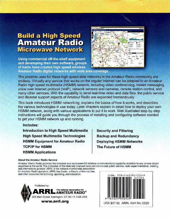
Includes:
Introduction to High Speed Multimedia
High Speed Multimedia Technologies
HSMM Equipment for Amateur Radio
TCP/IP for HSMM
HSMM Applications
About the Amateur Radio Service
Security and Filtering
Backup and Redundancy
Deploying HSMM Networks
The Future of HSMM
Amateur (Ham) Radio provides the broadest and most powerful wireless communications capability available to any private citizen anywhere in the world. The principles of this federally licensed radio service include public service, radio experimentation, training, and international goodwill. ARRL is the national membership association for Amateur Radio operators. ARAL has books, software, online courses, and other resources for licensing, operating, and education.
~t ARRL The national ll8SOClation for t AMATEUR RADIO® t Published by:
t' 225 Main Street, Newington. CT 06111-1494 USA
www.arrl.org
ISB N: 978-1-62 595 -0 52 - 9 5 279 5
9 781625 950529
USA $27.95 ARRL Item No. 0529