Design and optimization of propylene purification processes ...
236
UNIVERSIDAD DE CANTABRIA ESCUELA DE DOCTORADO DE LA UNIVERSIDAD DE CANTABRIA DOCTORADO EN INGENIERÍA QUÍMICA DE LA ENERGÍA Y DE PROCESOS Diseño y optimización de procesos de purificación de propileno mediante membranas de alto rendimiento PVDF- HFP/BMImBF 4 /AgBF 4 Memoria de tesis doctoral presentada para optar al título de Doctor por la Universidad de Cantabria Presentada por: Raúl Zarca Lago Dirigida por: Prof. Dra. Inmaculada Ortiz Uribe Dr. Alfredo Ortiz Sainz de Aja Santander, 2018 DESIGN AND OPTIMIZATION OF PROPYLENE PURIFICATION PROCESSES USING HIGH PERFORMANCE PVDF- HFP/BMImBF 4 /AgBF 4 MEMBRANES
-
Upload
khangminh22 -
Category
Documents
-
view
1 -
download
0
Transcript of Design and optimization of propylene purification processes ...

UNIVERSIDAD DE CANTABRIA
ESCUELA DE DOCTORADO DE LA UNIVERSIDAD DE CANTABRIA
DOCTORADO EN INGENIERÍA QUÍMICA DE LA ENERGÍA Y DE PROCESOS
Diseño y optimización de procesos de purificación de propileno
mediante membranas de alto rendimiento PVDF-
HFP/BMImBF4/AgBF4
Memoria de tesis doctoral presentada para optar al título de Doctor por la Universidad de Cantabria
Presentada por:
Raúl Zarca Lago
Dirigida por:
Prof. Dra. Inmaculada Ortiz Uribe
Dr. Alfredo Ortiz Sainz de Aja
Santander, 2018
DESIGN AND OPTIMIZATION OF PROPYLENE PURIFICATION PROCESSES USING HIGH PERFORMANCE PVDF-
HFP/BMImBF4/AgBF4 MEMBRANES


Programa de Doctorado en Ingeniería Química, de la Energía y de
Procesos (BOE núm. 16, de 19 de enero de 2015. RUCT: 5601000)
The research described in this thesis has been conducted at the
Advanced Separation Processes (ASP) Research Group of the Department
of Chemical and Biomolecular Engineering of the University of Cantabria.
This research has been financially supported by the Spanish Ministry
of Economy and Competitiveness and the European Regional
Development Fund through the projects: CTQ2012-31639 (MINECO-
FEDER, UE), “New separation processes with kinetic control based on the
use of functionalized materials”; CTQ2015-66078-R (MINECO-FEDER,
UE), “Advanced separation applications. Modeling and experimental
validation”; CTQ2016-75158-R (MINECO-FEDER, UE), “Composite
selective membranes and their implementation in microfluidic devices”.
Raúl Zarca also would like to express his gratitude to the University
of Cantabria for the postgraduate fellowship (B.O.C. 13 mayo 2015) and
the financial support to conduct a short research stay at the Department of
Chemical and Biomolecular Engineering, National University of
Singapore, (September-December 2016) under the supervision of Prof.
Chung Tai-Shung.


This PhD thesis document has been performed as a compendium of
interrelated scientific publications. The scientific articles that enable this
dissertation modality are published in international journals indexed in the
Journal Citation Reports (JCR):
R. Zarca, A. Ortiz, D. Gorri, I. Ortiz, A practical
approach to fixed-site-carrier facilitated transport
modeling for the separation of propylene/propane
mixtures through silver-containing polymeric
membranes, Sep. Purif. Technol. 180 (2017) 82-
89.
R. Zarca, A. Ortiz, D. Gorri, I. Ortiz, Generalized
predictive modeling for facilitated transport
membranes accounting for fixed and mobile
carriers, J. Memb. Sci. 542 (2017) 168–176.
R. Zarca, A. Ortiz, D. Gorri, L.T. Biegler, I.
Ortiz, Optimized distillation coupled with state-
of-the-art membranes for propylene purification,
J. Memb. Sci. 556 (2018) 321–328.


vii
Table of Contents
Summary / Resumen ix
Chapter 1. Introduction 1
1.1. Propylene industrial relevance 2 1.2. Propane/propylene separation. Traditional methods and
membrane technology. 6 1.3. Facilitated transport modelling 12 1.4. Facilitated transport membrane processes. Design and
optimization. 14 1.5. Background and scope 17 1.6. References 19 Chapter 2. Experimental and modeling methods 27
2.1. Experimental Methods 28 2.2. Facilitated transport modeling 38 2.3. Modeling and optimization of hybrid and multistage
membrane processes 44 2.4. References. 57
Chapter 3. Results summary 61
3.1. Membrane characterization 62 3.2. Gas permeation and mathematical modeling 70 3.3. Process design and optimization 79 3.4. References. 91

viii
Chapter 4. General conclusions and prospective view Conclusiones generales y perspectivas 93
4.1. Membrane characterization 94 4.2. Recommendations for future research 97 4.3. Conclusiones generales 98 4.4. Recomendaciones para investigación futura 102
Chapter 5. Scientific publications 103
5.1. JCR Scientific publications 104
Appendices 131
A.1. List of additional scientific publications 132 A.2. Contributions to scientific meetings 201 A.3. GAMS program used for hybrid process optimization 203 A.4. GAMS program used for multistage process optimization
(two-and-one-half-stages) 216
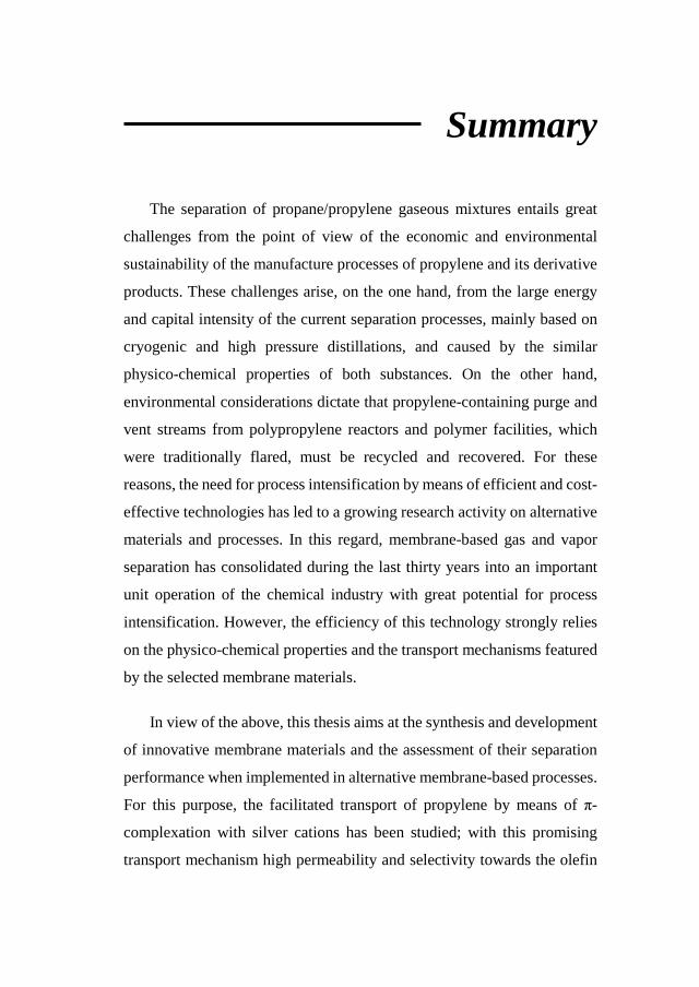
Summary
The separation of propane/propylene gaseous mixtures entails great
challenges from the point of view of the economic and environmental
sustainability of the manufacture processes of propylene and its derivative
products. These challenges arise, on the one hand, from the large energy
and capital intensity of the current separation processes, mainly based on
cryogenic and high pressure distillations, and caused by the similar
physico-chemical properties of both substances. On the other hand,
environmental considerations dictate that propylene-containing purge and
vent streams from polypropylene reactors and polymer facilities, which
were traditionally flared, must be recycled and recovered. For these
reasons, the need for process intensification by means of efficient and cost-
effective technologies has led to a growing research activity on alternative
materials and processes. In this regard, membrane-based gas and vapor
separation has consolidated during the last thirty years into an important
unit operation of the chemical industry with great potential for process
intensification. However, the efficiency of this technology strongly relies
on the physico-chemical properties and the transport mechanisms featured
by the selected membrane materials.
In view of the above, this thesis aims at the synthesis and development
of innovative membrane materials and the assessment of their separation
performance when implemented in alternative membrane-based processes.
For this purpose, the facilitated transport of propylene by means of π-
complexation with silver cations has been studied; with this promising
transport mechanism high permeability and selectivity towards the olefin

have been reached. The separation is achieved through the synthesis of
novel dense polymeric membranes integrating the use of a high
performance fluoropolymer (PVDF-HFP), an imidazolium-based ionic
liquid (IL) as a non-volatile additive (BMImBF4) and the silver salt that
provides the silver cations upon dissociation inside the membrane
(AgBF4).
The complexity of the resultant structure requires a thorough
characterization work in order to identify the interactions between the
membrane constituents. This characterization has been supported by
spectroscopic, thermogravimetric and microscopy techniques and the
results confirm the existence of the chemical species and interactions
required to yield the fixed-site and mobile carrier transport mechanisms.
Afterwards, the separation performance of the synthesized membranes
has been assessed through gas permeation experiments. First, the pure gas
diffusivity and solubility of propane and propylene in the PVDF-HFP and
PVDF-HFP/BMImBF4 matrices have been calculated through the time-lag
technique. Then, the mixed-gas separation performance of the PVDF-
HFP/BMImBF4/AgBF4 composite membranes under several operating
conditions, namely feed pressure, temperature and membrane composition,
has been analyzed using the continuous-flow permeation technique. The
experimental data obtained are later used for the development of a semi-
predictive mathematical model able to describe the propylene
transmembrane flux in the studied range of the operating variables.
Additional permeation experiments reveal the influence of silver
degradation during long-term permeation and the effect of feed humidity
on the membrane performance. Eventually, real gas mixtures provided by
a petrochemical company have been tested to assess the effect of potential
trace contaminant on the membrane stability.
In further pursuit of the main objective of this thesis, the industrial
applicability of the developed membranes has been explored through
design and optimization of membrane-based separation processes. First,
the retrofitting of an existing distillation process with a membrane stage
has been proposed, quantifying the potential operating costs reduction
achieved compared with the distillation base-case. Several membrane
materials including the proposed facilitated transport membranes are
considered for this optimization, which provides a wider insight into the
state-of-the-art of propylene-selective membranes. Lastly, multistage
membrane processes implementing the PVDF-HFP/BMImBF4/AgBF4
system have been studied to determine the feasibility of a complete
distillation replacement. In this case-study, the previously developed
mathematical model accounting for the gas transport mechanisms has been
introduced in the optimization, which allows a simultaneous optimization
of the membrane process and the membrane material.
Resumen
La separación de mezclas gaseosas propano/propileno entraña grandes
retos desde el punto de vista de la sostenibilidad económica y
medioambiental de los procesos de fabricación de propileno y sus
productos derivados. Estos retos surgen, por un lado, de la elevada
intensidad energética y de capital de los actuales procesos de separación,
principalmente basados en destilaciones criogénicas o a alta presión, y
causada por las similares propiedades fisicoquímicas de ambas sustancias.
Y, por el otro lado, las nuevas consideraciones medioambientales dictan
que las corrientes de purga y venteo de los reactores de polimerización y
fábricas de polímeros que contienen propileno, tradicionalmente
quemadas, deben ser recicladas y recuperadas. Por ello, la necesidad de
alcanzar la intensificación de procesos por medio de tecnologías eficientes
y rentables ha dado lugar a una creciente actividad de investigación sobre
materiales y procesos alternativos. En este sentido, la separación de gas y
vapor basada en membranas se ha consolidado en los últimos treinta años
como una importante operación unitaria de la industria química con un
gran potencial para la intensificación de procesos. Sin embargo, la
eficiencia de esta tecnología depende enormemente de las propiedades
fisicoquímicas y de los mecanismos de transporte presentados por los
materiales de membrana seleccionados.
En vista de lo anterior, esta tesis tiene como objetivo la síntesis y el
desarrollo de materiales de membrana innovadores y el estudio de su
capacidad de separación cuando se implementan en procesos alternativos
de separación basados en membranas. Para este propósito, se ha estudiado

el transporte facilitado de propileno por medio de complejación π con
cationes de plata; con este prometedor mecanismo de transporte se han
obtenido elevados valores de permeabilidad y selectividad hacia la olefina.
La separación se consigue mediante la síntesis de novedosas membranas
densas poliméricas que integran el uso de un fluoropolímero (PVDF-HFP),
un líquido iónico (IL) basado en el imidazol como aditivo no-volátil
(BMImBF4) y una sal de plata que provee los cationes plata tras su
disociación en el interior de la membrana (AgBF4).
La complejidad de la estructura resultante requiere un exhaustivo
trabajo de caracterización para identificar las interacciones entre los
componentes de la membrana. Esta caracterización se ha soportado en
técnicas espectroscópicas, termogravimétricas y de microscopía y los
resultados confirman la existencia de las especies químicas y las
interacciones necesarias para dar lugar a los mecanismos de transporte por
carrier fijo y móvil.
Posteriormente, la capacidad de separación de las membranas
sintetizadas se ha analizado mediante experimentos de permeación.
Primero, la difusividad y solubilidad de propano y propileno en las
matrices de PVDF-HFP y PVDF-HFP/BMImBF4 se ha calculado
mediante la técnica de time-lag con gases puros. Luego, la capacidad de
separación de mezclas gaseosas de la membrana compuesta PVDF-
HFP/BMImBF4/AgBF4 bajo diferentes condiciones de operación,
principalmente presión de alimentación, temperatura y composición de la
membrana, se ha analizado usando la técnica de permeación de flujo en
continuo. Los datos experimentales obtenidos son usados posteriormente
para el desarrollo de un modelo matemático semipredictivo capaz de
describir el flujo transmembranal de propileno en el rango estudiado de las
variables de operación.
Experimentos de permeación adicionales revelan la influencia de la
degradación de la plata durante la permeación en períodos prolongados y
el efecto de la humedad de la corriente de alimentación en el desempeño
de la membrana. Finalmente, mezclas reales suministradas por una
compañía petroquímica han sido empleadas para analizar el efecto de
potenciales contaminantes minoritarios en la estabilidad de la membrana.
Continuando con el objetivo principal de esta tesis, la aplicabilidad
industrial de las membranas desarrolladas se ha analizado mediante el
diseño y la optimización de procesos de separación basados en estas
membranas. Primero, se propone el reacondicionamiento de una columna
de destilación existente por medio de una etapa previa de membranas,
cuantificando los potenciales ahorros en los costes de operación logrados
en comparación con el caso base, esto es, cuando solo se emplea la
columna. Para esta optimización se consideran diferentes materiales de
membrana, incluyendo las membranas desarrolladas durante esta tesis, lo
que da una visión más amplia del estado del arte de las membranas
selectivas al propileno. Finalmente, se han estudiado procesos de
membrana de múltiples etapas implementando el sistema PVDF-
HFP/BMImBF4/AgBF4 para determinar la viabilidad de un sustitución
completa de la destilación. En este caso de estudio se ha introducido en la
optimización el modelo matemático previamente desarrollado, lo que ha
permitido una optimización simultánea del proceso y el material.
Chapter 1 Introduction
Abstract
Propylene (C3H6) is the second-largest-volume chemical produced
globally, mainly driven by the production of polypropylene resins. The
impact of this commodity chemical in the world’s economy has been
growing in the last decades and the notable importance of its wide list of
derivative products guarantees that this trend will continue. This
introductory chapter offers a general overview of the propylene industrial
relevance, as well as the current production methods and the issues
concerning the separation of propylene/propane mixtures. Then,
membrane technology for propylene purification is introduced,
emphasizing the facilitated transport membrane technology and the use of
ionic liquids as novel additives. Moreover, a brief review on mathematical
modeling and process design and optimization of membrane processes is
presented. Finally, the background and scope of this thesis is summarized.

Introduction
2
1.1. Propylene industrial relevance
Propylene is one of the most important building blocks in the
petrochemical industry. Its global annual demand is estimated at, roughly,
90 million tonnes, only exceeded by ethylene, the other major light olefin
[1]. Nonetheless, propylene shows a greater diversity of derivatives. The
major derivative produced from propylene is polypropylene, the second
most produced thermoplastic material, with a market share of 26% among
all thermoplastics [2]. But other specialized products derived from
propylene include the cumene value chain (phenol, acetone, bisphenol A,
polycarbonate), epoxies, propylene oxide, phenol-formaldehyde resins,
acrylic acid, acrylonitrile, n-butyl alcohol, isopropyl alcohol and 2-
ethylhexanol. Figure 1.1 depicts the propylene demand contribution of
each derivative.
Figure. 1.1. Propylene demand.
Chapter 1
3
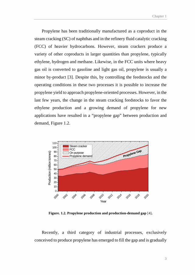
Propylene has been traditionally manufactured as a coproduct in the
steam cracking (SC) of naphthas and in the refinery fluid catalytic cracking
(FCC) of heavier hydrocarbons. However, steam crackers produce a
variety of other coproducts in larger quantities than propylene, typically
ethylene, hydrogen and methane. Likewise, in the FCC units where heavy
gas oil is converted to gasoline and light gas oil, propylene is usually a
minor by-product [3]. Despite this, by controlling the feedstocks and the
operating conditions in these two processes it is possible to increase the
propylene yield to approach propylene-oriented processes. However, in the
last few years, the change in the steam cracking feedstocks to favor the
ethylene production and a growing demand of propylene for new
applications have resulted in a “propylene gap” between production and
demand, Figure 1.2.
2000
2002
2004
2006
2008
2010
2012
2014
2016
2018
2020
0102030405060708090
100110
Prod
uctio
n (m
illion
tonn
es)
Year
Steam cracker FCC On purpose Propylene demand Propylene Gap
Figure. 1.2. Propylene production and production-demand gap [4].
Recently, a third category of industrial processes, exclusively
conceived to produce propylene has emerged to fill the gap and is gradually

Introduction
4
gaining importance among the production processes. These so called “on-
purpose” processes, include propane dehydrogenation, olefin metathesis
and methanol-to-olefins process (MTO). Figure 1.3 summarizes the
propylene production routes.
Figure. 1.3. Propylene production routes.
After the cracking processes, sequential distillation columns are used
to split each fraction of the resulting gas stream. In this way, after
separating the C1 and C2 fractions in the so called deethanizer column, a
depropanizer is used to split the C3 fraction from C4+ products. Figure 1.4
schematizes the distillation sequence.
MTO Dehydrogenation Steam Cracking FCC Olefin Conversion
PROPYLENE
METHANOL
METHANE
PROPANE
BUTHANE ETHANE
PROPANE
BUTHANE
NAPHTA GAS OIL
ETHYLENE
BUTHYLENES
From natural gas
From crude oil
Intermediate product

Chapter 1
5
Figure. 1.4. Post-cracking separation sequence.
Typical product specification for propylene is divided into two
categories: the high-pure polymer-grade, dedicated to the polypropylene
industry, and the less pure chemical-grade, further used in most of the
derivatives industry [3]. Table 1.1 displays the product specifications of
each grade.
The polymerization reactions that take place during the polypropylene
production require high propylene purity with propane concentrations
typically below 0.5 mol.%, along with a complete removal of minor
contaminants, such as carbonyl sulfide, which can poison the
polymerization catalysts.
LIGHT GAS
ETHYLENE
ETHANE
C4+
PROPYLENE
PROPANE
FEED
DEETHANIZER
DEPROPANIZER
C2 SPLITTER
C3 SPLITTER

Introduction
6
Table 1.1. Propylene most common product specification.
Chemical grade Polymer grade
Propene, mol. % 92-95 99.5-99.8 Acetylene, ppm <10 <2 Ethylene, ppm <20 <20 Ethane, ppm <2000 <100 Propyne, ppm <20 <5 Propadiene, ppm <20 <5 C4+,ppm <1000 <10 Hydrogen, ppm <10 <10 Nitrogen, ppm <50 <50 Oxygen, ppm <5 <5 Carbon monoxide, ppm <5 <5 Carbon dioxide, ppm <5 <5 Sulfur, mass ppm <5 <1 Water, mol. ppm <25 <10 Propane remainder remainder
Given that the C3 fraction from the depropanizer head stream contains
both the olefin and its homologous paraffin (i.e. propane), effective
separation methods are required to produce a propylene product in the
specified purities.
1.2. Propane/propylene separation. Traditional methods and
membrane technology.
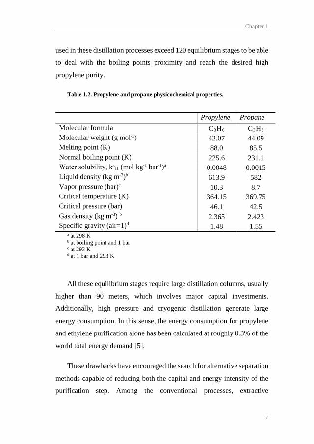
The propane and propylene molecules show very similar
physicochemical properties, as shown in Table 1.2. For this reason, the
industrial separation of propane/propylene mixtures has traditionally relied
on cryogenic and high pressure distillation, exploiting the minor boiling
point variation between these two components. Typically, the columns
Chapter 1
7
used in these distillation processes exceed 120 equilibrium stages to be able
to deal with the boiling points proximity and reach the desired high
propylene purity.
Table 1.2. Propylene and propane physicochemical properties.
Propylene Propane
Molecular formula C3H6 C3H8 Molecular weight (g mol-1) 42.07 44.09 Melting point (K) 88.0 85.5 Normal boiling point (K) 225.6 231.1 Water solubility, kᵒH (mol kg-1 bar-1)a 0.0048 0.0015 Liquid density (kg m-3)b 613.9 582 Vapor pressure (bar)c 10.3 8.7 Critical temperature (K) 364.15 369.75 Critical pressure (bar) 46.1 42.5 Gas density (kg m-3) b 2.365 2.423 Specific gravity (air=1)d 1.48 1.55
a at 298 K b at boiling point and 1 bar c at 293 K d at 1 bar and 293 K
All these equilibrium stages require large distillation columns, usually
higher than 90 meters, which involves major capital investments.
Additionally, high pressure and cryogenic distillation generate large
energy consumption. In this sense, the energy consumption for propylene
and ethylene purification alone has been calculated at roughly 0.3% of the
world total energy demand [5].
These drawbacks have encouraged the search for alternative separation
methods capable of reducing both the capital and energy intensity of the
purification step. Among the conventional processes, extractive
Introduction
8
distillation, physical adsorption and physical/chemical absorption are the
most commonly studied [6–8]. However, the economic feasibility of the
first two processes is hampered by solvent usage and capital costs, and,
although chemical adsorption through transition metal complexation has
proven certain competitiveness, it has not been widely introduced in the
industry due to complex regeneration cycles and low olefin load capacities
[9].
In the last few years, increasing attention has been paid to membrane
technology, a compact, modular and energy efficient solution that allows
process intensification by implementing: “…more or less complex
technologies that replace large, expensive, energy-intensive equipment or
processes with ones that are smaller, less costly and more efficient…” [10].
The synthesis of effective olefin/paraffin separation membranes has
been approached exploring several transport phenomena. The simplest way
is to exploit the intrinsic separation properties of dense polymers, based on
the solution-diffusion theory [11]. In this way, the membrane can
discriminate different molecules due to permeability and/or solubility
differences. Dense polymeric membranes made of glassy, rubbery and
cellulosic polymers have been reported, but they usually perform high
propylene selectivity at the expense of low permeability [12–15].
Another widely reported approach contemplates the molecular sieving
effect of some advanced materials. These materials feature a combination
of micro and ultramicropores able to discriminate different molecules
based on their molecular size [16]. Among these materials, polymers with
intrinsic microscopy (PIMs) [17,18], metal organic frameworks (MOFs)

Chapter 1
9
[19,20], carbon molecular sieves (CMSs) [21,22] and graphene-based
membranes [23] are the most notable.
However, the intrinsic separation properties of polymers are vastly
improved when the capability of some transition metals (i.e. copper and
silver) to form olefin-metal complexes is exploited. This complexation
phenomenon, explained through the Dewar-Chatt-Duncanson model
(Figure 1.5), consists in a selective and reversible bonding caused by the
donation of electrons from olefin to metal [24]. The use of this
complexation mechanism has given rise to a new kind of membrane
materials featuring facilitated transport mechanisms [25].
Figure. 1.5. Dewar-Chatt-Duncanson model of π-complexation (adapted from [24]).
The first attempts to introduce facilitated transport in membrane
technology involved the use of liquid membranes, most notably in the form
of supported liquid membranes (SLM). In these membranes a liquid
solvent containing the carrier (i.e. silver salt) is introduced into the pores
Ag
C
C
+
++
+
+
-
-
--
Olefin π orbital(bonding)
Olefin π* orbital(antibonding)
Metal 4D orbital
Metal 5S orbital
σ component of electron donnor/acceptor interactionπ component of electron donnor/acceptor interaction

Introduction
10
of a polymeric support where the complexation reaction dramatically
increases the olefin solubility. Due to the partial pressure gradient, the
complex is transported to the permeate side, where decomplexation takes
place. However, poor mechanical stability and solvent losses caused by
evaporation and dragging prevent SLMs from becoming an industrial
alternative [26–28].
Recently, researchers have tried to solve these drawbacks by replacing
traditional organic solvents with novel room temperature ionic liquids
(RTILs). These compounds are exclusively formed by ions. The relative
size difference between the anion and the cation prevents these ionic
substances from organizing in crystalline structures, which results in the
liquid state at room temperature. Besides their negligible vapor pressure,
ionic liquids are non-flammable excellent solvents whose chemical and
physical properties can be tailored by a judicious selection of cation, anion,
and substituents [29,30]. However, although their negligible vapor
pressure eliminates the solvent evaporation issue, the introduction of
RTILs cannot solve the other major issue of supported liquid membranes,
which is the expelling out of solvent from the support pores due to the
transmembrane pressure.
Advanced mechanical stability and separation performance can be
achieved combining the properties of dense polymeric membranes with
facilitated transport through the synthesis of polymer/salt systems. In these
systems, the silver salt is dissolved along with the polymer and the
membrane is then fabricated through solvent casting, which results in a
dense facilitated transport membrane usually described as a polymer
electrolyte [31,32]. In polymers containing electron donor heteroatoms
such as oxygen or fluorine, the Pearson’s Hard-Soft–Acid-Base (HSAB)

Chapter 1
11
theory predicts the formation of weak interactions between the Ag+ cations
(soft acid) and the polymer heteroatoms (hard bases) [33]. These
interactions are weak enough to still allow the π-complexation between the
metal cation and the olefin. As a result, the silver cations remain “fixed” to
the polymer backbone and the permeating olefin molecules follow a
“hopping” pathway from active site to active site, this has come to be called
“fixed site carrier transport mechanism” [34,35]. Figure 1.6 schematizes
the fixed site carrier mechanism.
Figure. 1.6. Fixed site carrier transport mechanism.
Room temperature ionic liquids can be effectively implemented to
improve the membrane performance of polymer electrolyte membranes.
The presence of an ionic liquid within the free volume of the polymer
promotes dissociation and mobility of the silver cations, which, after
binding to the olefin, will diffuse through the membrane following a
“mobile carrier” transport mechanism, similar to that of the facilitated
transport liquid membranes [36].
Finally, the selection of the silver salt counterion plays a major role in
the cation capability to dissociate and interact with the olefin. Low
Ag-C3H6+
Ag+
Electron donnor heteroatom
Ag-C3H6+
Ag+
Polymer chain
Introduction
12
electronegative large anions such as BF4-, CF3SO3
-, and ClO4- form salts
featuring a low lattice energy, whereas high electronegative small anions
like F-, Cl- and NO3- form high lattice energy salts, hindering olefin-silver
coordination and impeding facilitated transport [37,38].
Solid state facilitated transport membranes have proven promising
potential for olefin/paraffin separation, thanks to their mechanical stability
and remarkable performance. However, a future replacement of traditional
distillation by facilitated transport membranes requires of rigorous process
design and optimization based on comprehensive mathematical models
able to predict the system response to a wide range of operational variables
and parameters.
1.3. Facilitated transport modelling
Several approaches have been reported in the literature for the
mathematical modeling of facilitated transport in solid membranes. The
dual sorption model, originally developed to interpret gas sorption in
glassy polymers, has been commonly used to explain facilitated transport
due to its simplicity and conceptual analogy to the mass transport with
fixed carrier membranes. However, this model does not predict facilitated
transport without direct diffusion between carriers [39].
A more rigorous analysis of facilitated transport in solid membranes is
achieved by introducing the “effective diffusion coefficient” between fixed
site carriers. In this analysis, the concentration of unreacted fixed carrier is
assumed to be constant, implying large excess of carrier. If the reaction
rate is much faster than the diffusion rate, then the model is reduced to the
dual sorption transport model at low partial pressure of the solute. But, at

Chapter 1
13
high solute partial pressures, the assumption of excess carrier is violated
and the model stars to gradually deviate from experimental data [35,40].
Another interesting model proposed by Cussler et al. [34] introduces
the concept of “limited mobility of chained carriers”. This model assumes
fast reaction on the membrane surface, thus, no uncomplexed solute can
exist within the membrane. The polymer chains rearrangement motion
allows a complexed molecule to find another uncomplexed carrier in the
vicinity, resulting in facilitated transport.
All these models explain facilitated transport considering only direct
diffusion between carriers and such diffusion requires the distance between
carriers to be shorter than the diffusional jump distance of a given
gas/polymer pair. However, facilitated transport has been experimentally
observed in membranes that do not satisfy this condition, suggesting that
some sort of solute diffusion in uncomplexed state may also occur between
fixed sites [41].
Finally, the “concentration fluctuation model”, a description of
facilitated transport that does not consider solute “hopping” between fixed
sites has been reported [42,43]. Apart from the thermodynamic constant,
this model also considers the reaction kinetics. According to this model the
facilitation effect is produced by the local fluctuation in the solute
concentration along the membrane thickness due to complexation-
decomplexation reactions. This fluctuation increases the chemical
potential of the permeant species according to Cahn’s theory [44], which
results in a higher driving force.
A good mathematical model capable of describing the solute
transmembrane flux in the common operating conditions range can be
Introduction
14
decisive for the rigorous design and optimization of facilitated transport
membrane processes.
1.4. Facilitated transport membrane processes. Design and
optimization.
The complete replacement of traditional distillation by a single-stage
membrane process capable of producing polymer grade propylene and fuel
grade propane simultaneously is not feasible, due to the purity-recovery
trade-off inherent in membrane operation and the industrially achievable
pressure ratio [45]. Accordingly, alternative strategies should be
considered to introduce membrane technology in the olefin/paraffin
separation.
A first approach consists in the implementation of hybrid separation
processes combining membrane and distillation technology [46,47]. Such
processes can potentially reduce the energy intensity of the olefin/paraffin
separation process by a factor of 2 or 3 [5]. The membrane/distillation
hybrid processes comprise a limited number of arrangements, including
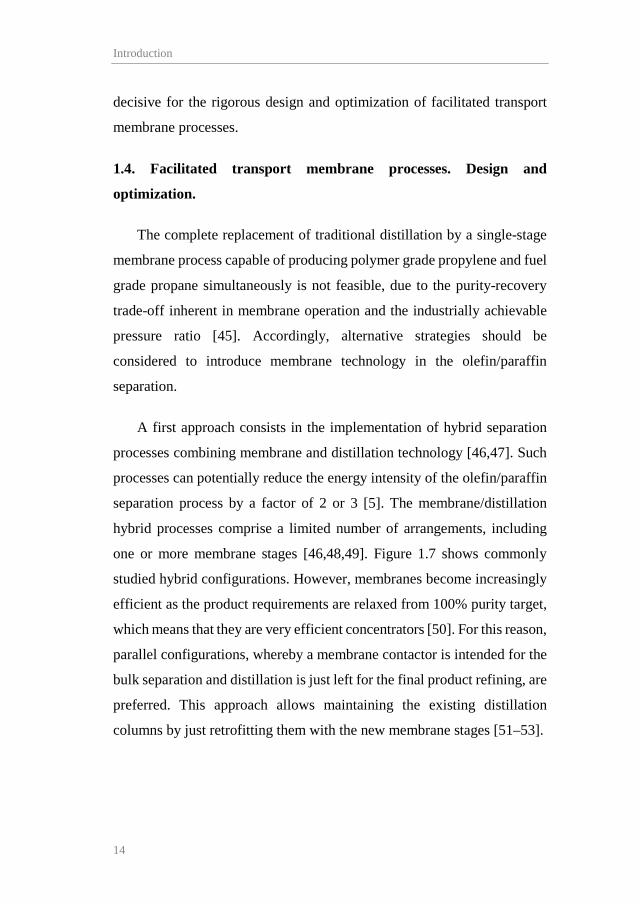
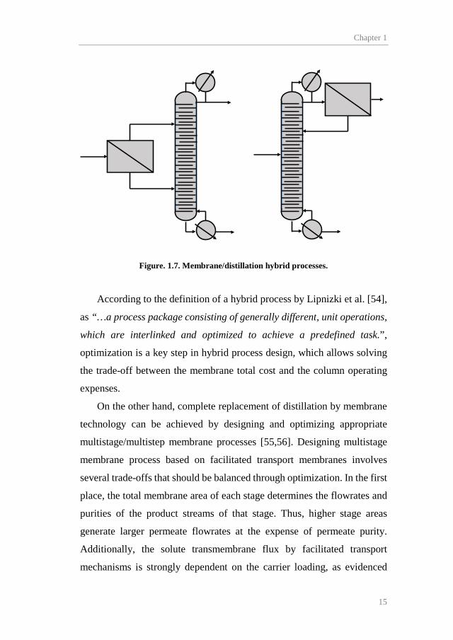
one or more membrane stages [46,48,49]. Figure 1.7 shows commonly
studied hybrid configurations. However, membranes become increasingly
efficient as the product requirements are relaxed from 100% purity target,
which means that they are very efficient concentrators [50]. For this reason,
parallel configurations, whereby a membrane contactor is intended for the
bulk separation and distillation is just left for the final product refining, are
preferred. This approach allows maintaining the existing distillation
columns by just retrofitting them with the new membrane stages [51–53].
Chapter 1
15
Figure. 1.7. Membrane/distillation hybrid processes.
According to the definition of a hybrid process by Lipnizki et al. [54],
as “…a process package consisting of generally different, unit operations,
which are interlinked and optimized to achieve a predefined task.”,
optimization is a key step in hybrid process design, which allows solving
the trade-off between the membrane total cost and the column operating
expenses.
On the other hand, complete replacement of distillation by membrane
technology can be achieved by designing and optimizing appropriate
multistage/multistep membrane processes [55,56]. Designing multistage
membrane process based on facilitated transport membranes involves
several trade-offs that should be balanced through optimization. In the first
place, the total membrane area of each stage determines the flowrates and
purities of the product streams of that stage. Thus, higher stage areas
generate larger permeate flowrates at the expense of permeate purity.
Additionally, the solute transmembrane flux by facilitated transport
mechanisms is strongly dependent on the carrier loading, as evidenced

Introduction
16
from the experimental analysis and the mathematical models [57,58].
However, high carrier concentrations imply high membrane cost per unit
area, which could affect the process economics. Finally, higher
transmembrane pressures increase the driving force available for the
permeation but at the expense of higher recompression requirements.
Unlike hybrid processes, membrane processes can be designed in
many different configurations combining multiple stages, stages with
multiple steps and recycle streams. Hence, optimization is crucial to
determine the optimal layout for each specific separation. Although it is
possible to expand the optimization to cover all configurations by building
a complex superstructure that includes membranes, mixers, splitters and
compressors, such optimization results in a complex mixed integer
nonlinear programming problem (MINLP) [59]. MINLP problems are
difficult to solve because they combine challenges of nonlinear and mixed
integer programming, and require dedicated methods for its resolution
[60]. Additionally, most studies dealing with superstructure optimization
for gas separation conclude with a two-stage optimal configuration [61–
64].
For this reason, selecting the most promising configurations based on
the extensive literature seems to be the most efficient strategy. This allows
solving less complex non-linear programming problems (NLP) and pay
more attention to the facilitated transport particularities through the
implementation of transport models in the optimization.

Chapter 1
17
1.5. Background and scope
This thesis has been performed in the Advanced Separation Processes
research group of the University of Cantabria. In previous works of this
group, the propane and propylene solubility in RTIL/Ag+ mixtures was
studied, revealing the exothermic character of the complexation reaction
and its reversibility through vigorous agitation and vacuum [65,66].
Subsequently, the reactive absorption kinetics of propylene in
RTIL/Ag+ media was assessed, determining the required physicochemical
parameters to predict the absorption rates [67].
In order to study the industrial applicability of propylene reactive
absorption in the proposed RTIL/Ag+ media, several works reported the
use of membrane contactors, assessing the influence of feed composition
and silver loading [68]. Furthermore, supported ionic liquid membranes
(SILMs) were also synthesized and tested [57].
During this period, the quantum chemical COSMO-RS method was
applied to determine the most suitable system (ionic liquid/silver salt) to
carry out the separation of propane/propylene gas mixtures by reactive
absorption, concluding that the optimal medium should be based on an
ionic liquid with the BF4 anion and an ammonium or imidazolium-based
cation and silver tetrafluoroborate (AgBF4) as a silver salt.
Finally, a first study on polymer/ionic liquid composite membranes for
propane/propylene separation was reported [69]. The use of ionic liquids
as additives had previously proven certain advantages such as improved
carrier stability and enhanced membrane permeability. In that study,
PVDF-HFP/BMImBF4 membranes were characterized through polarized

Introduction
18
light microscopy, gas permeation and tensile tests, concluding that the
membrane with 80% polymer-20% IL w/w showed the best compromise
between separation properties and mechanical resistance.
Based on the above-mentioned results, the main objective of this thesis
is to assess the potential of the proposed facilitated transport membranes
to offer a more efficient alternative to current propane/propylene
separation processes. In the first place, this work contributes and makes
progress to the fundamental knowledge of the phenomena involved in the
propylene permeation in PVDF-HFP/BMImBF4/AgBF4 facilitated
transport membranes. With this regard, a wide range of characterization
techniques has been implemented to study the internal structure and the
interactions between the membrane constituents. Additionally, time-lag
and gas-mixture continuous-flow permeation techniques allowed
determining the separation performance under different operating
conditions, including changes in temperature, feed pressure, silver loading,
feed humidity and feed composition. On the other hand, this work advances
in the implementation of facilitated transport membranes in alternative
separation processes. For this purpose and based on experimental data, a
mathematical model able to describe the propylene permeation through
carrier-mediated mechanisms under the previously studied operating
conditions has been developed. Finally, based on process economics,
hybrid membrane/distillation and multistage membrane processes have
been proposed and optimized using computer aided process design. These
studies predicted the economic savings that these membranes can
potentially produce.
Chapter 1
19
1.6. References
[1] J.S. Plotkin, The Propylene Gap: How can it be filled?, Am. Chem.
Soc. (2015).
[2] C. Cathelin, M. Dorini, G. Mei, J. Pater, R. Rinaldi, Polypropylene,
Kirk-Othmer Encycl. Chem. Technol. (2018) 27.
[3] H. Zimmermann, Propene, Ullmann’s Encycl. Ind. Chem. (n.d.)
2013.
[4] A. Akah, M. Al-Ghrami, Maximizing propylene production via
FCC technology, Appl. Petrochemical Res. 5 (2015) 377–392.
[5] D.S. Sholl, R.P. Lively, Seven chemical separations to change the
world, Nature. 532 (2016) 435–437.
[6] R. Kumar, J.M. Prausnitz, C.J. King, Process design considerations
for extractive distillation: separation of propylene-propane, in:
Dimitrios P. Tassios (Ed.), Extr. Azeotropic Distill., 1972: pp. 16–
34.
[7] C.M. Shu, S. Kulvaranon, M.E. Findley, A.I. Liapis, Experimental
and computational studies on propane-propylene separation by
adsorption and variable-temperature stepwise desorption, Sep.
Technol. 1 (1990) 18–28.
[8] R.T. Yang, pi-Complexation Sorbents and Applications, in:
Adsorbents Fundam. Appl., John Wiley & Sons, Hoboken, NJ,
2003: p. 424.
[9] D.J. Safarik, R.B. Eldridge, Olefin/Paraffin Separations by
Reactive Absorption: A Review, Ind. Eng. Chem. Res. 37 (1998)
2571–2581.
[10] J.C. Charpentier, In the frame of globalization and sustainability,
process intensification, a path to the future of chemical and process
engineering (molecules into money), Chem. Eng. J. 134 (2007) 84–

Introduction
20
[11] J.G. Wijmans, R.W. Baker, The solution-diffusion model: a review,
J. Memb. Sci. 107 (1995) 1–21.
[12] O.M. Ilinitch, G.L. Semin, M.V. Chertova, K.I. Zamaraev, Novel
polymeric membranes for separation of hydrocarbons, J. Memb.
Sci. 66 (1992) 1–8.
[13] K. Okamoto, A. Taguchi, J. Hao, K. Tanaka, H. Kita, Permeation
and separation properties of polyimide membranes to olefins and
paraffins, J. Memb. Sci. 121 (1996) 197–207.
[14] A. Ito, S.-T. Hwang, Permeation of propane and propylene through
cellulosic polymer membranes, J. Appl. Polym. Sci. 38 (1989) 483–
490.
[15] R. Faiz, K. Li, Polymeric membranes for light olefin/paraffin
separation, Desalination. 287 (2012) 82–97.
[16] W.J. Koros, C. Zhang, Materials for next-generation molecularly
selective synthetic membranes, Nat. Mater. 16 (2017) 289–297.
[17] R.J. Swaidan, X. Ma, E. Litwiller, I. Pinnau, Enhanced
propylene/propane separation by thermal annealing of an
intrinsically microporous hydroxyl-functionalized polyimide
membrane, J. Memb. Sci. 495 (2015) 235–241.
[18] K.S. Liao, J.Y. Lai, T.S. Chung, Metal ion modified PIM-1 and its
application for propylene/propane separation, J. Memb. Sci. 515
(2016) 36–44.
[19] V.F.D. Martins, A.M. Ribeiro, A. Ferreira, U.H. Lee, Y.K. Hwang,
J.S. Chang, J.M. Loureiro, A.E. Rodrigues, Ethane/ethylene
separation on a copper benzene-1,3,5-tricarboxylate MOF, Sep.
Purif. Technol. 149 (2015) 445–456.
[20] M. Hartmann, U. Böhme, M. Hovestadt, C. Paula, Adsorptive
Separation of Olefin/Paraffin Mixtures with ZIF-4, Langmuir. 31

Chapter 1
21
(2015) 12382–12389.
[21] O. Salinas, X. Ma, Y. Wang, Y. Han, I. Pinnau, Carbon molecular
sieve membrane from a microporous spirobisindane-based
polyimide precursor with enhanced ethylene/ethane mixed-gas
selectivity, RSC Adv. 7 (2017) 3265–3272.
[22] R.J. Swaidan, X. Ma, I. Pinnau, Spirobisindane-based polyimide as
efficient precursor of thermally-rearranged and carbon molecular
sieve membranes for enhanced propylene/propane separation, J.
Memb. Sci. 520 (2016) 983–989.
[23] H.-X. Sun, B.-B. Yuan, P. Li, T. Wang, Y.-Y. Xu, Preparation of
nanoporous graphene and the application of its nanocomposite
membrane in propylene/propane separation, Funct. Mater. Lett. 08
(2015) 1550019.
[24] O.C.C.P.I.I. I, O.C. Compounds, P.I.I.I.I. Spectra, Olefin Co-
ordination Compounds. Part I I I . 2939 586., (1952) 2939–2947.
[25] R. Faiz, K. Li, Olefin/paraffin separation using membrane based
facilitated transport/chemical absorption techniques, Chem. Eng.
Sci. 73 (2012) 261–284.
[26] M. Teramoto, H. Matsuyama, T. Yamashiro, Y. Katayama,
Separation of Ethylene From Ethane By Supported Liquid
Membranes Containing Silver-Nitrate As a Carrier, J. Chem. Eng.
Japan. 19 (1986) 419–424.
[27] S. Duan, A. Ito, A. Ohkawa, Separation of propylene/propane
mixture by a supported liquid membrane containing triethylene
glycol and a silver salt, J. Memb. Sci. 215 (2003) 53–60.
[28] M.T. Ravanchi, T. Kaghazchi, A. Kargari, Supported liquid
membrane separation of propylene-propane mixtures using a metal
ion carrier, Desalination. 250 (2010) 130–135.

Introduction
22
[29] T. Welton, Room-Temperature Ionic Liquids. Solvents for
Synthesis and Catalysis, Chem. Rev. 99 (1999) 2071–2084.
[30] J.P. Hallett, T. Welton, Room-temperature ionic liquids: Solvents
for synthesis and catalysis. 2, Chem. Rev. 111 (2011) 3508–3576.
[31] Y. Yoon, J. Won, Y.S. Kang, Polymer electrolyte membranes
containing silver ion for facilitated olefin transport,
Macromolecules. 33 (2000) 3185–3186.
[32] L. Liu, X. Feng, A. Chakma, Unusual behavior of poly(ethylene
oxide)/AgBF4 polymer electrolyte membranes for olefin-paraffin
separation, Sep. Purif. Technol. 38 (2004) 255–263.
[33] R.G. Pearson, Hard and Soft Acids and Bases, J. Am. Chem. Soc.
85 (1963) 3533–3539.
[34] E.L. Cussler, R. Aris, A. Bhown, On the limits of facilitated
diffusion, J. Memb. Sci. 43 (1989) 149–164.
[35] R.D. Noble, Analysis of facilitated carrier membranes transport
with fixed site, 50 (1990) 207–214.
[36] D.R. Smith, J.A. Quinn, The facilitated transport of carbon
monoxide through cuprous chloride solutions, AIChE J. 26 (1980)
112–120.
[37] J.H. Kim, B.R. Min, J. Won, S.H. Joo, H.S. Kim, Y.S. Kang, Role
of polymer matrix in polymer/silver complexes for structure,
interactions, and facilitated olefin transport, Macromolecules. 36
(2003) 6183–6188.
[38] C.K. Kim, J. Won, H.S. Kim, Y.S. Kang, H.G. Li, C.K. Kim,
Density functional theory studies on the dissociation energies of
metallic salts: Relationship between lattice and dissociation
energies, J. Comput. Chem. 22 (2001) 827–834.
[39] H. Nishide, M. Ohyanagi, O. Okada, E. Tsuchida, Dual-Mode
Chapter 1
23
Transport of Molecular Oxygen in a Membrane Containing a
Cobalt Porphyrin Complex as a Fixed Carrier, Macromolecules. 20
(1987) 417–422.
[40] R.D. Noble, Generalized microscopic mechanism of facilitated
transport in fixed site carrier membranes, J. Memb. Sci. 75 (1992)
121–129.
[41] E. Tsuchida, H. Nishide, M. Ohyanagi, H. Kawakami, P.
Chemistry, R. October, Facilitated Transport of Molecular Oxygen
in the Membranes of Polymer-Coordinated Cobalt Schiff Base
Complexes, (1987) 1907–1912.
[42] Y.S. Kang, J.M. Hong, J. Jang, U.Y. Kim, Analysis of facilitated
transport in solid membranes with fixed site carriers: 1. Single RC
circuit model, J. Memb. Sci. 109 (1996) 149–157.
[43] J.M. Hong, Y.S. Kang, J. Jang, U.Y. Kim, Analysis of facilitated
transport in polymeric membrane with fixed site carrier: 2. Series
RC circuit model, J. Memb. Sci. 109 (1996) 159–163.
[44] J.W. Cahn, Phase separation by spinodal decomposition in isotropic
systems, J. Chem. Phys. 42 (1965) 93–99. doi:10.1063/1.1695731.
[45] H.B. Park, J. Kamcev, L.M. Robeson, M. Elimelech, B.D. Freeman,
Maximizing the right stuff: The trade-off between membrane
permeability and selectivity, Science (80-. ). 356 (2017) 1138–
1148.
[46] T.G. Pressly, K.M. Ng, A Break-Even Analysis of Distillation-
Membrane Hybrids, AIChE J. 44 (1998) 93–105.
[47] A. Norkobilov, D. Gorri, I. Ortiz, Comparative study of
conventional, reactive-distillation and pervaporation integrated
hybrid process for ethyl tert-butyl ether production, Chem. Eng.
Process. Process Intensif. 122 (2017) 434–446.
Introduction
24
[48] W. Stephan, R.D. Noble, C.A. Koval, Design methodology for a
membrane/distillation column hybrid process, J. Memb. Sci. 99
(1995) 259–272.
[49] T. Pettersen, A. Argo, R.D. Noble, C.A. Koval, Design of combined
membrane and distillation processes, Sep. Technol. 6 (1996) 175–
187.
[50] R. Spillman, Economics of gas separation membrane processes, in:
R.D. Noble, S.A. Stern (Eds.), Membr. Sep. Technol. Princ. Appl.,
Elsevier Science, 1995.
[51] S. Moganti, R.D. Noble, C.A. Koval, Analysis of a
membrane/distillation column hydrid process, J. Memb. Sci. 93
(1994) 31–44.
[52] J.A. Caballero, I.E. Grossmann, M. Keyvani, E.S. Lenz, N. Square,
V. Pennsyl, Design of hybrid distillation - vapor membrane
separation systems, Ind. Eng. Chem. Res. 48 (2009) 9151–9162.
[53] I.K. Kookos, Optimal Design of Membrane/Distillation Column
Hybrid Processes, Ind. Eng. Chem. Res. 42 (2003) 1731–1738.
[54] F. Lipnizki, R.W. Field, P.-K. Ten, Pervaporation-based hybrid
process: a review of process design, applications and economics, J.
Memb. Sci. 153 (1999) 183–210.
[55] R.W. Baker, Membrane Technology and Applications, 3rd Editio,
Wiley, Chichester, 2012.
[56] F. Ahmad, K.K. Lau, A.M. Shariff, G. Murshid, Process simulation
and optimal design of membrane separation system for CO2capture
from natural gas, Comput. Chem. Eng. 36 (2012) 119–128.
[57] M. Fallanza, A. Ortiz, D. Gorri, I. Ortiz, Experimental study of the
separation of propane/propylene mixtures by supported ionic liquid
membranes containing Ag+–RTILs as carrier, Sep. Purif. Technol.

Chapter 1
25
97 (2012) 83–89.
[58] R. Zarca, A. Ortiz, D. Gorri, I. Ortiz, Generalized predictive
modeling for facilitated transport membranes accounting for fixed
and mobile carriers, J. Memb. Sci. 542 (2017) 168–176.
[59] R. Qi, M.A. Henson, Membrane system design for multicomponent
gas mixtures via mixed-integer nonlinear programming, Comput.
Chem. Eng. 24 (2000) 2719–2737.
[60] K. Zhou, X. Chen, Z. Shao, W. Wan, L.T. Biegler, Heterogeneous
parallel method for mixed integer nonlinear programming, Comput.
Chem. Eng. 66 (2014) 290-0300.
[61] B. Ohs, J. Lohaus, M. Wessling, Optimization of membrane based
nitrogen removal from natural gas, J. Memb. Sci. 498 (2016) 291–
301.
[62] C. Kunde, A. Kienle, Global optimization of multistage binary
separation networks, Chem. Eng. Process. - Process Intensif.
(2018).
[63] D.C. Nymeijer, T. Visser, R. Assen, M. Wessling, Composite
hollow fiber gas-liquid membrane contactors for olefin/paraffin
separation, Sep. Purif. Technol. 37 (2004) 209–220.
[64] A. Aliaga-Vicente, J.A. Caballero, M.J. Fernandez-Torres,
Synthesis and Optimization of Membrane Cascade for Gas
Separation via Mixed-Integer Nonlinear Programming, AIChE J.
63 (2017) 1989–2006.
[65] A. Ortiz, A. Ruiz, D. Gorri, I. Ortiz, Room temperature ionic liquid
with silver salt as efficient reaction media for propylene/propane
separation: Absorption equilibrium, Sep. Purif. Technol. 63 (2008)
311–318.
[66] A. Ortiz, L. Galán, D. Gorri, B. De Haan, I. Ortiz, Reactive Ionic
Introduction
26
Liquid Media for the Separation of Propylene / Propane Gaseous
Mixtures, Ind. Eng. Chem. Res. 49 (2010) 7227–7233.
[67] A. Ortiz, L.M. Galán, D. Gorri, A.B. De Haan, I. Ortiz, Kinetics of
reactive absorption of propylene in RTIL-Ag+ media, Sep. Purif.
Technol. 73 (2010) 106–113.
[68] A. Ortiz, D. Gorri, Á. Irabien, I. Ortiz, Separation of
propylene/propane mixtures using Ag+-RTIL solutions. Evaluation
and comparison of the performance of gas-liquid contactors, J.
Memb. Sci. 360 (2010) 130–141.
[69] M. Fallanza, A. Ortiz, D. Gorri, I. Ortiz, Polymer-ionic liquid
composite membranes for propane/propylene separation by
facilitated transport, J. Memb. Sci. 444 (2013) 164–172.

Chapter 2 Experimental and modeling methods
Abstract
In this chapter, the materials and the experimental and modeling
procedures used during this thesis are summarized. First, the materials and
the experimental methods regarding membrane synthesis, characterization
of the membrane structure and determination of the separation
performance are presented. Next, the modeling methodology used to
develop a mathematical description of the propylene transmembrane flux
through facilitated transport mechanisms is described. Finally, the design
and optimization strategies used to assess the facilitated transport
membranes industrial applicability are discussed.
Experimental and modeling methods
28
2.1. Experimental Methods
This section presents the materials and methods used for membrane
synthesis, followed by a brief presentation of the membrane
characterization techniques and a more detailed description of the gas
permeation set-ups and methodologies.
2.1.1. Chemicals
Propylene and propane gases were supplied by Praxair with a purity of
99.5%. Poly(vinylidene fluoride-co-hexafluoropropylene) (PVDF-HFP)
was purchased from Sigma Aldrich. 1-Butyl-3-methylimidazolium
tetrafluoroborate (BMImBF4) with a minimum purity of 99% and halide
content of less than 500 ppm was supplied by Iolitec. Silver
tetrafluoroborate (AgBF4) with a minimum purity of 99% was supplied by
Apollo Scientific Ltd. Tetrahydrofuran (THF) purchased from Panreac was
used as solvent for membrane synthesis. The industrial propane/propylene
gas mixture was kindly provided by Petronor S.A., Table 2.1 shows the
industrial mixture composition. All chemicals were used as received
without further purification.
2.1.2. Membrane synthesis
The proposed membranes for propane/propylene separation are
composed of a polymer, an ionic liquid and a silver salt. Poly(vinylidene
fluoride-co-hexafluoropropylene) (PVDF-HFP) is a high performance
fluoropolymer featuring high thermal, chemical and mechanical stability,
and is used to form the polymeric dense matrix. Based on previous results
of the research group, the ionic liquid used in this work has been 1- butyl3-
methylimidazolium tetrafluoroborate (BMImBF4) since it provided the

Chapter 2
29
best results in terms of separation selectivity and propylene solubility and
presents good miscibility with both the PVDF-HFP and the silver salt.
Finally, silver tetrafluoroborate (AgBF4) provides the silver cations upon
dissociation inside the membrane thanks to the low lattice energy provided
by the anion [1].
Table 2.1. Industrial gas mixture composition.
Component Concentration (mol.% )
Methane 0.0034
Ethane 0.1503
Ethylene 0.0099
Propane 24.8837
Propylene 74.7208
Isobutane 0.1872
N-butane 0.0016
Trans-butene 0.0214
Iso-butene 0.0218
Hydrogen sulfide < 0.2 ppm
Acetylene < 0.2 ppm
Hydrogen < 0.2 ppm
All the studied membranes were prepared by the solvent casting
method. The desired amount of PVDF-HFP was dissolved in THF using a
10 ml sealed glass vial to avoid solvent losses by evaporation. The content
was stirred during 24 h at room temperature. To achieve complete
dissolution of the polymer, the mixture was subjected to a heating step at

Experimental and modeling methods
30
50 °C during 5 min. After that, the selected amounts of ionic liquid and
silver salt were added to the solution and the whole mixture was stirred at
room temperature during 15 min. The membrane precursor was poured in
a glass petri dish and then introduced in a vacuum oven overnight at 800
mbar and 25 °C. Finally, a more severe evaporation step at full vacuum (~1
mbar) during 1 h was performed for further solvent removal. Light
exposure was avoided during the whole synthesis process to prevent silver
reduction. The thickness of the synthesized membranes ranged from 40 to
100 µm depending on the specific composition. For calculation purposes,
the real membrane thickness was measured using a digital micrometer
Mitutoyo Digimatic MDC-25SX (accuracy±0.001 mm).
2.1.3. Characterization techniques
The cross-section and surface morphology of the membranes were
observed using scanning electron microscopy (Carl Zeiss EVO MA 15).
The samples were prepared by immersing and fracturing the membranes in
liquid nitrogen followed by gold sputtering with a Balzers Union SCD040
sputter coating system.
Further knowledge on membrane structure can be extracted from the
energy dispersive X-ray spectroscopy (EDX). EDX makes use of x-ray
spectrum emitted by the solid sample bombarded with a focused beam of
electrons to obtain a localized chemical analysis. When the sample is hit
by the electron beam, electrons are ejected from the atoms of the sample's
surface. The resulting electron vacancies are filled by electrons from a
higher energy state, and an x-ray is emitted to balance the energy difference
between the two electrons' states. The x-ray energy is characteristic of the
element from which it was emitted. EDX was used in conjunction with

Chapter 2
31
SEM to obtain scan-lines and plot-mapping patterns of elemental silver on
cross-sectional images of the composite membrane.
Thermogravimetric analyses were performed using a TG-DTA 60H
Shimadzu thermobalance to assess the potential water uptake of the studied
membranes under humid feed conditions.
The interactions between the Ag+ cations and the fluorine atoms of the
polymer chains were studied through Fourier transform infrared
spectroscopy (FTIR) analyzing the polymer CF2 symmetrical stretching
mode. FTIR spectra were recorded using a Perkin Elmer Spectrum Two
spectrometer
Better insight on the AgBF4 dissociation behavior was achieved using
Raman spectroscopy to analyze the regions of the BF4- stretching bands in
the pure AgBF4 and the silver-containing membranes. Raman
spectroscopy was carried out using a Horiba T64000 triple spectrometer
equipped with a confocal microscope and a Jobin Yvon Symphony CCD
detector cooled with liquid nitrogen. A 488 nm beam from a Kr-Ar ion
laser was focused through a 100x objective, using 2 mW laser power in all
measurements. The spectral curves were fitted using Lorentzian functions.
X-ray photoelectron spectroscopy (XPS) was used to expand the
knowledge on membrane structure and silver degradation though the
analysis of the silver oxidation states. Additionally, the Ag 3d regions of
the XPS spectra can confirm the interactions between the silver cations and
the polymer fluorine atoms. XPS spectra were acquired using an SPECS
(Berlin, Germany) X-ray photoelectron spectrometer. The samples were
analyzed using a Mg anode operated at 225 W (E=1253.6 eV, 13 kV, 17.5
mA). The carbon (C 1s) line at 284.8 eV was used as reference in our
Experimental and modeling methods
32
determinations of the silver binding energies. A scanning interval of 0.1
eV was used for the final spectrum acquisition.
2.1.4. Gas permeation techniques
The constant-volume variable-pressure time-lag technique was used to
experimentally obtain the transport and equilibrium parameters (i.e.
diffusivity and solubility) of the gaseous species in the membrane matrix
according to the solution-diffusion theory.
Figure 2.1 shows the experimental setup used to conduct the
permeation experiments using the time-lag technique. This apparatus
consists of two chambers separated by the membrane (47 mm in diameter).
Before each run, the residual gas in both chambers and in the permeation
cell is evacuated using a vacuum pump. At time zero the gas of interest is
introduced into the upper chamber. The feed pressure is maintained
constant at the upper chamber while the pressure increase in the lower
chamber, which occurs due to the passage of gas through the membrane, is
recorded. The pressure increase in the lower chamber starts only after a
period of time known as the time-lag (Ө). After the time-lag, the diffusion
process continues in the quasi-steady state until the pressure in both
chambers is equalized.

Chapter 2
33
Figure. 2.1. Time-lag apparatus: 1) gas cylinder, 2) pressure controller, 3) gas valves,
4) pressure transducers, 5) permeation chamber, 6) vacuum pump, 7) data
recording, 8) permeation cell, 9) temperature-controlled section.
The mathematical expression that describes the pressure increase in the
lower chamber can be deduced by applying Fick’s second law in the limits
of the membrane. By integrating Fick’s equation with the boundary
conditions using Laplace transforms, operating and neglecting terms, the
expression for the pressure in the permeate chamber versus time in the
quasi-steady state flux is obtained:
P
P1
2
3
3
3
3
4
45
6
7
9
8
Experimental and modeling methods
34
𝑃𝑃𝐿𝐿(𝑡𝑡) = 𝐴𝐴𝑅𝑅 · 𝑇𝑇 · 𝑆𝑆 · 𝐷𝐷 · 𝑃𝑃0
𝑉𝑉 · 𝐿𝐿 �𝑡𝑡 −𝐿𝐿2
6𝐷𝐷�
(1)
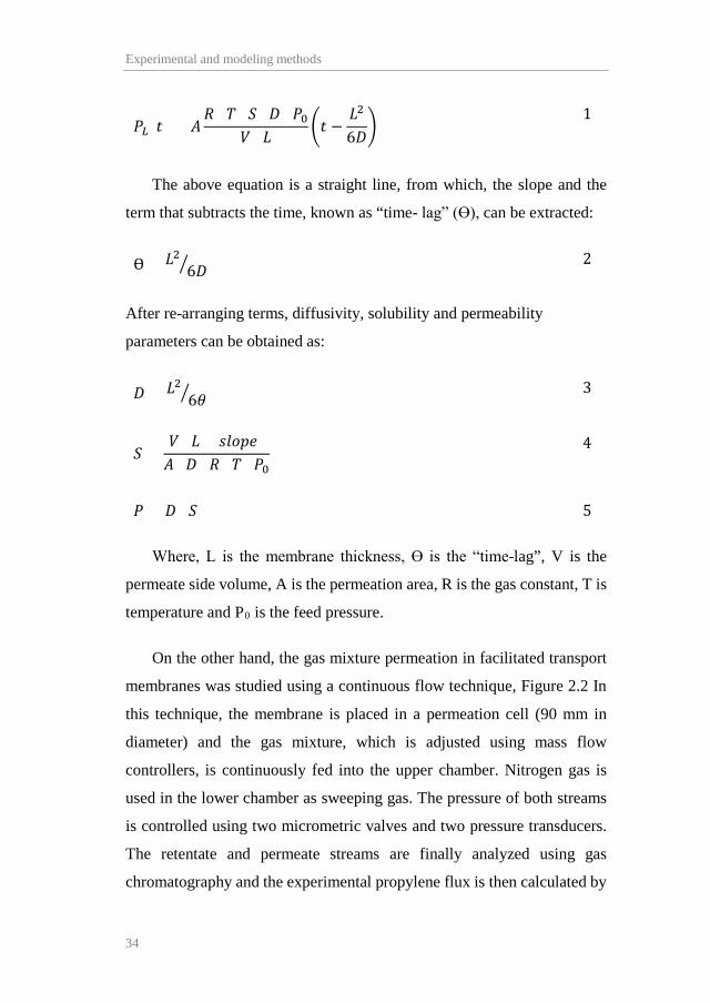
The above equation is a straight line, from which, the slope and the
term that subtracts the time, known as “time- lag” (Ө), can be extracted:
Ө = 𝐿𝐿26𝐷𝐷� (2)
After re-arranging terms, diffusivity, solubility and permeability
parameters can be obtained as:
𝐷𝐷 = 𝐿𝐿26𝜃𝜃� (3)
𝑆𝑆 =𝑉𝑉 · 𝐿𝐿 · (𝑠𝑠𝑠𝑠𝑠𝑠𝑠𝑠𝑠𝑠)𝐴𝐴 · 𝐷𝐷 · 𝑅𝑅 · 𝑇𝑇 · 𝑃𝑃0
(4)
𝑃𝑃 = 𝐷𝐷 · 𝑆𝑆 (5)
Where, L is the membrane thickness, Ө is the “time-lag”, V is the
permeate side volume, A is the permeation area, R is the gas constant, T is
temperature and P0 is the feed pressure.
On the other hand, the gas mixture permeation in facilitated transport
membranes was studied using a continuous flow technique, Figure 2.2 In
this technique, the membrane is placed in a permeation cell (90 mm in
diameter) and the gas mixture, which is adjusted using mass flow
controllers, is continuously fed into the upper chamber. Nitrogen gas is
used in the lower chamber as sweeping gas. The pressure of both streams
is controlled using two micrometric valves and two pressure transducers.
The retentate and permeate streams are finally analyzed using gas
chromatography and the experimental propylene flux is then calculated by
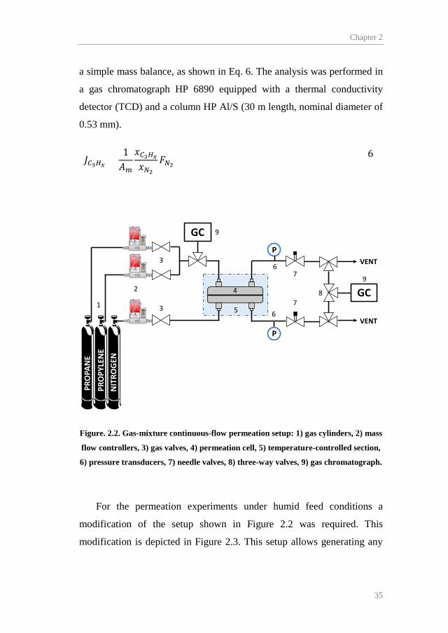
Chapter 2
35
a simple mass balance, as shown in Eq. 6. The analysis was performed in
a gas chromatograph HP 6890 equipped with a thermal conductivity
detector (TCD) and a column HP Al/S (30 m length, nominal diameter of
0.53 mm).
𝐽𝐽𝐶𝐶3𝐻𝐻𝑥𝑥 =1𝐴𝐴𝑚𝑚
𝑥𝑥𝐶𝐶3𝐻𝐻𝑥𝑥𝑥𝑥𝑁𝑁2
𝐹𝐹𝑁𝑁2 (6)
Figure. 2.2. Gas-mixture continuous-flow permeation setup: 1) gas cylinders, 2) mass
flow controllers, 3) gas valves, 4) permeation cell, 5) temperature-controlled section,
6) pressure transducers, 7) needle valves, 8) three-way valves, 9) gas chromatograph.
For the permeation experiments under humid feed conditions a
modification of the setup shown in Figure 2.2 was required. This
modification is depicted in Figure 2.3. This setup allows generating any
P
P
1
VENT
PRO
PAN
EPR
OPY
LEN
EN
ITRO
GEN
VENT
GC
GC
2
3
3
4
5
6
6
7
78
9
9

Experimental and modeling methods
36
desired relative humidity in the feed stream by controlling the ratio of dry
to humid feed.
Figure. 2.3. Modification of the feed line setup to control the relative humidity of the
feed stream.
Finally, permeation tests with real gas mixtures provided by the
petrochemical industry were performed to assess if the membrane
performance is affected by known contaminant trace components
potentially present in industrial streams (i.e. acetylene, hydrogen sulfide
and hydrogen [2]). The composition of these mixtures is shown in Table
2.1.
GAS A
GAS B
TO PERMEATION
CELL
MASS FLOW CONTROLLERS
GAS BUBBLER

Chapter 2
37
2.1.5. Experimental sequence
The experimental sequence for the time lag permeation tests is shown
in Table 2.2. The feed pressure in the upper chamber was fixed at 3.5 bar
while the permeate chamber was under vacuum.
Table 2.2. Time-lag technique experimental sequence.
Temperature (K) Membrane C3H6 C3H8
298 PVDF-HFP • • PVDF-HFP/BMImBF4
a • •
308 PVDF-HFP • • PVDF-HFP/BMImBF4
a - -
318 PVDF-HFP • • PVDF-HFP/BMImBF4
a - - a Polymer/ionic liquid membrane composition was 80/20 wt.%
On the other hand, the experimental conditions for the gas-mixture
continuous-flow permeation tests are shown in Table 2.3. The synthetic
feed used in these experiments consisted of an equimolar
propane/propylene gas mixture.
The silver loading indicated in Table 2.3 was calculated as the mass of
silver salt added to 1 g of polymer or polymer/ionic liquid matrix. In this
regard, silver loadings of 20, 40, 60 and 80 % were used during the
experimental studies. However, these silver loadings produced different
silver concentrations, expressed in mol/l, depending on the resulting
membrane thickness of each specimen. For this reason, the specific silver
concentration of each membrane will be indicated in the results section.

Experimental and modeling methods
38
Table 2.3. Experimental conditions for the gas-mixture continuous-flow
permeation tests.
Experimental condition Value T (K) 293/303/313 Feed composition Synthetic/Industrial Feed side pressure (bar) 1-4 Permeate side pressure (bar) 1 Silver load (wt.%)a 20/40/60/80 Polymer/ionic liquid mass ratio (100/0) - (80/20) Relative humidity (%RH) 0/25/50/100 a Calculated as the silver mass added over the polymer or polymer/ionic liquid mass.
2.2. Facilitated transport modeling
The gas transport mechanisms occurring inside the membrane are the
result of the complex membrane structure. For this reason, the complexity
of the composite membrane was approached by simplifying its nature,
considering that the facilitated transport mechanism is shared between
fixed site and mobile carrier, accounting for bounded and unbounded silver
cations, respectively. A schematic representation of the transport
mechanisms is depicted in Figure 2.4.

Chapter 2
39
Figure. 2.4. Schematic representation of the gas transport mechanisms.
The total propylene flux through the membrane may be calculated as
the sum of the contribution of each transport mechanism [3]:
𝐽𝐽𝐶𝐶3𝐻𝐻6 = −𝐷𝐷𝐶𝐶3𝐻𝐻6,𝑚𝑚𝑑𝑑𝐶𝐶𝐶𝐶3𝐻𝐻6𝑑𝑑𝑥𝑥
− 𝐴𝐴𝑑𝑑𝐶𝐶𝐶𝐶3𝐻𝐻6𝑑𝑑𝑥𝑥
− 𝐵𝐵𝑑𝑑𝐶𝐶𝐶𝐶3𝐻𝐻6𝑑𝑑𝑥𝑥
(7)
The parameters A and B represent the “effective diffusivity” of the
organometallic complex species in the mobile carrier and fixed-site carrier
mechanisms respectively. Eq. 7 can be integrated along the membrane
domain:
𝐽𝐽𝐶𝐶3𝐻𝐻6 = 𝐷𝐷𝐶𝐶3𝐻𝐻6,𝑚𝑚𝐶𝐶𝐶𝐶3𝐻𝐻60 − 𝐶𝐶𝐶𝐶3𝐻𝐻6
𝐿𝐿
𝐿𝐿+ 𝐴𝐴
𝐶𝐶𝐶𝐶3𝐻𝐻60 − 𝐶𝐶𝐶𝐶3𝐻𝐻6
𝐿𝐿
𝐿𝐿
+ 𝐵𝐵𝐶𝐶𝐶𝐶3𝐻𝐻60 − 𝐶𝐶𝐶𝐶3𝐻𝐻6
𝐿𝐿
𝐿𝐿
(8)
Where subscripts 0 and L refer to feed and permeate sides,
respectively. If sorption equilibrium at the interphase is assumed, Eq. 8 can
be reformulated as:
Propylene Propane Ag+
SOLUTION-DIFFUSION FIXED-SITE CARRIER MOBILE CARRIER
Experimental and modeling methods
40
𝐽𝐽𝐶𝐶3𝐻𝐻6 = 𝐷𝐷𝐶𝐶3𝐻𝐻6,𝑚𝑚 · 𝑆𝑆𝐶𝐶3𝐻𝐻6,𝑚𝑚𝑠𝑠𝐶𝐶3𝐻𝐻60 − 𝑠𝑠𝐶𝐶3𝐻𝐻6
𝐿𝐿
𝐿𝐿+ 𝑃𝑃𝑐𝑐𝑐𝑐𝑚𝑚𝑐𝑐
𝑠𝑠𝐶𝐶3𝐻𝐻60 − 𝑠𝑠𝐶𝐶3𝐻𝐻6
𝐿𝐿
𝐿𝐿
+ 𝐾𝐾𝐻𝐻𝑠𝑠𝐶𝐶3𝐻𝐻60 − 𝑠𝑠𝐶𝐶3𝐻𝐻6
𝐿𝐿
𝐿𝐿
(9)
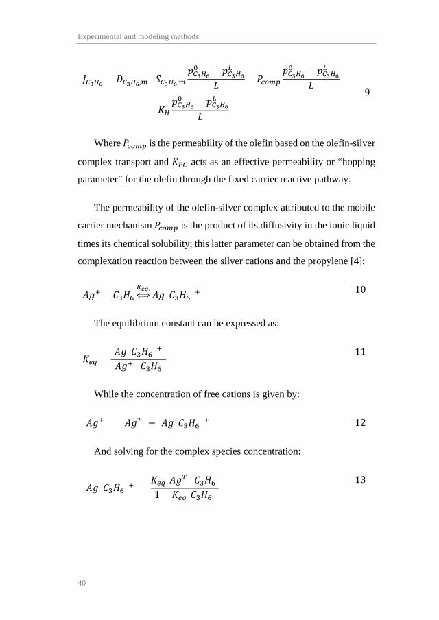
Where 𝑃𝑃𝑐𝑐𝑐𝑐𝑚𝑚𝑐𝑐 is the permeability of the olefin based on the olefin-silver
complex transport and 𝐾𝐾𝐹𝐹𝐶𝐶 acts as an effective permeability or “hopping
parameter” for the olefin through the fixed carrier reactive pathway.
The permeability of the olefin-silver complex attributed to the mobile
carrier mechanism 𝑃𝑃𝑐𝑐𝑐𝑐𝑚𝑚𝑐𝑐 is the product of its diffusivity in the ionic liquid
times its chemical solubility; this latter parameter can be obtained from the
complexation reaction between the silver cations and the propylene [4]:
𝐴𝐴𝐴𝐴+ + 𝐶𝐶3𝐻𝐻6𝐾𝐾𝑒𝑒𝑒𝑒.�� 𝐴𝐴𝐴𝐴(𝐶𝐶3𝐻𝐻6)+ (10)
The equilibrium constant can be expressed as:
𝐾𝐾𝑒𝑒𝑒𝑒 =[𝐴𝐴𝐴𝐴(𝐶𝐶3𝐻𝐻6)+][𝐴𝐴𝐴𝐴+][𝐶𝐶3𝐻𝐻6]
(11)
While the concentration of free cations is given by:
[𝐴𝐴𝐴𝐴+] = [𝐴𝐴𝐴𝐴𝑇𝑇] − [𝐴𝐴𝐴𝐴(𝐶𝐶3𝐻𝐻6)+] (12)
And solving for the complex species concentration:
[𝐴𝐴𝐴𝐴(𝐶𝐶3𝐻𝐻6)+] =𝐾𝐾𝑒𝑒𝑒𝑒[𝐴𝐴𝐴𝐴𝑇𝑇][𝐶𝐶3𝐻𝐻6]1 + 𝐾𝐾𝑒𝑒𝑒𝑒[𝐶𝐶3𝐻𝐻6]
(13)
Chapter 2
41
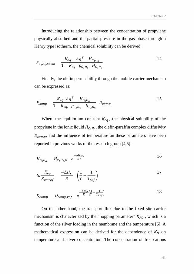
Introducing the relationship between the concentration of propylene
physically absorbed and the partial pressure in the gas phase through a
Henry type isotherm, the chemical solubility can be derived:
𝑆𝑆𝐶𝐶3𝐻𝐻6,𝑐𝑐ℎ𝑒𝑒𝑚𝑚 =𝐾𝐾𝑒𝑒𝑒𝑒 · [𝐴𝐴𝐴𝐴𝑇𝑇] · 𝐻𝐻𝐶𝐶3𝐻𝐻6
1 + 𝐾𝐾𝑒𝑒𝑒𝑒 · 𝑠𝑠𝐶𝐶3𝐻𝐻6 · 𝐻𝐻𝐶𝐶3𝐻𝐻6
(14)
Finally, the olefin permeability through the mobile carrier mechanism
can be expressed as:
𝑃𝑃𝑐𝑐𝑐𝑐𝑚𝑚𝑐𝑐 =𝐾𝐾𝑒𝑒𝑒𝑒.[𝐴𝐴𝐴𝐴𝑇𝑇] · 𝐻𝐻𝐶𝐶3𝐻𝐻6
1 + 𝐾𝐾𝑒𝑒𝑒𝑒. · 𝑠𝑠𝐶𝐶3𝐻𝐻6 · 𝐻𝐻𝐶𝐶3𝐻𝐻6· 𝐷𝐷𝑐𝑐𝑐𝑐𝑚𝑚𝑐𝑐
(15)
Where the equilibrium constant 𝐾𝐾𝑒𝑒𝑒𝑒., the physical solubility of the
propylene in the ionic liquid 𝐻𝐻𝐶𝐶3𝐻𝐻6, the olefin-paraffin complex diffusivity
𝐷𝐷𝑐𝑐𝑐𝑐𝑚𝑚𝑐𝑐, and the influence of temperature on these parameters have been
reported in previous works of the research group [4,5]:
𝐻𝐻𝐶𝐶3𝐻𝐻6 = 𝐻𝐻𝐶𝐶3𝐻𝐻6,0 · 𝑠𝑠−∆𝐻𝐻𝑠𝑠𝑠𝑠𝑠𝑠 𝑅𝑅𝑇𝑇 (16)
𝑠𝑠𝑙𝑙𝐾𝐾𝑒𝑒𝑒𝑒
𝐾𝐾𝑒𝑒𝑒𝑒,𝑟𝑟𝑒𝑒𝑟𝑟 =
−∆𝐻𝐻𝑟𝑟 𝑅𝑅
· �1𝑇𝑇−
1𝑇𝑇𝑟𝑟𝑒𝑒𝑟𝑟
� (17)
𝐷𝐷𝑐𝑐𝑐𝑐𝑚𝑚𝑐𝑐 = 𝐷𝐷𝑐𝑐𝑐𝑐𝑚𝑚𝑐𝑐,𝑟𝑟𝑒𝑒𝑟𝑟 · 𝑠𝑠−𝐸𝐸𝐸𝐸𝐷𝐷 𝑅𝑅 �1𝑇𝑇 − 1
𝑇𝑇𝑟𝑟𝑒𝑒𝑟𝑟�
(18)
On the other hand, the transport flux due to the fixed site carrier
mechanism is characterized by the “hopping parameter” 𝐾𝐾𝐹𝐹𝐶𝐶 , which is a
function of the silver loading in the membrane and the temperature [6]. A
mathematical expression can be derived for the dependence of 𝐾𝐾𝐻𝐻 on
temperature and silver concentration. The concentration of free cations

Experimental and modeling methods
42
ready to coordinate with propylene molecules to form the coordination
complex can be derived from the chemical equilibrium. In this regard, the
heterogeneous complexation reaction between propylene and silver cations
bound to the polymer matrix is depicted by the following equation:
[𝐴𝐴𝐴𝐴+] + 𝑠𝑠𝐶𝐶3𝐻𝐻6𝐾𝐾𝑝𝑝⇔ [𝐴𝐴𝐴𝐴(𝐶𝐶3𝐻𝐻6)+] (19)
The equilibrium constant can be expressed as:
𝐾𝐾𝑐𝑐 =[𝐴𝐴𝐴𝐴(𝐶𝐶3𝐻𝐻6)+][𝐴𝐴𝐴𝐴+]𝑠𝑠𝐶𝐶3𝐻𝐻6
0 (20)
Introducing Eq. 12 and solving for the free silver cations
concentration:
[𝐴𝐴𝐴𝐴+] =[𝐴𝐴𝐴𝐴𝑇𝑇]
1 + 𝐾𝐾𝑐𝑐 · 𝑠𝑠𝐶𝐶3𝐻𝐻60
(21)
The proportionality between the value of 𝐾𝐾𝐹𝐹𝐶𝐶 and the variables is
defined through the fitting parameter α:
𝐾𝐾𝐹𝐹𝐶𝐶 = 𝛼𝛼 �[𝐴𝐴𝐴𝐴𝑇𝑇]
1 + 𝐾𝐾𝑐𝑐 · 𝑠𝑠𝐶𝐶3𝐻𝐻60 � 𝑠𝑠
𝐸𝐸𝐸𝐸𝐹𝐹𝐹𝐹𝑅𝑅 � 1
293−1𝑇𝑇�
(22)
In Eq. 22 the influence of temperature in the hopping mechanism has
been described through an Arrhenius-type expression, and the term in
brackets refers to the concentration of free “uncomplexed” silver cations,
as obtained from the heterogeneous chemical equilibrium, Eq. 19. The
parameter α and the activation energy of the hopping parameter (𝐸𝐸𝐸𝐸𝐹𝐹𝐶𝐶) are
the two fitting parameters of the model.
Chapter 2
43
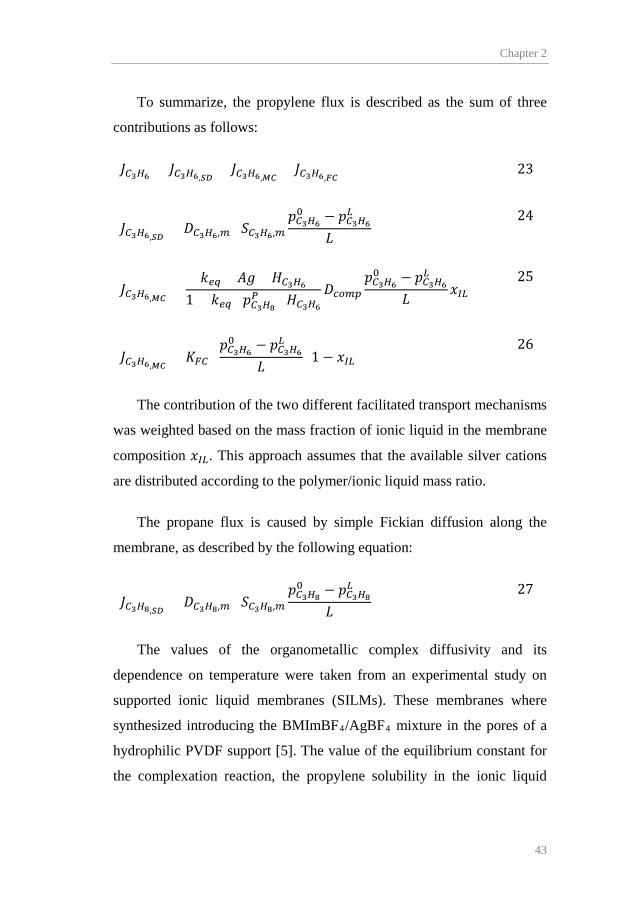
To summarize, the propylene flux is described as the sum of three
contributions as follows:
𝐽𝐽𝐶𝐶3𝐻𝐻6 = 𝐽𝐽𝐶𝐶3𝐻𝐻6,𝑆𝑆𝐷𝐷+ 𝐽𝐽𝐶𝐶3𝐻𝐻6,𝑀𝑀𝐹𝐹
+ 𝐽𝐽𝐶𝐶3𝐻𝐻6,𝐹𝐹𝐹𝐹 (23)
𝐽𝐽𝐶𝐶3𝐻𝐻6,𝑆𝑆𝐷𝐷= 𝐷𝐷𝐶𝐶3𝐻𝐻6,𝑚𝑚 · 𝑆𝑆𝐶𝐶3𝐻𝐻6,𝑚𝑚
𝑠𝑠𝐶𝐶3𝐻𝐻60 − 𝑠𝑠𝐶𝐶3𝐻𝐻6
𝐿𝐿
𝐿𝐿
(24)
𝐽𝐽𝐶𝐶3𝐻𝐻6,𝑀𝑀𝐹𝐹=
𝑘𝑘𝑒𝑒𝑒𝑒 · [𝐴𝐴𝐴𝐴] · 𝐻𝐻𝐶𝐶3𝐻𝐻61 + 𝑘𝑘𝑒𝑒𝑒𝑒 · 𝑠𝑠𝐶𝐶3𝐻𝐻8
𝑃𝑃 · 𝐻𝐻𝐶𝐶3𝐻𝐻6𝐷𝐷𝑐𝑐𝑐𝑐𝑚𝑚𝑐𝑐
𝑠𝑠𝐶𝐶3𝐻𝐻60 − 𝑠𝑠𝐶𝐶3𝐻𝐻6
𝐿𝐿
𝐿𝐿𝑥𝑥𝐼𝐼𝐿𝐿
(25)
𝐽𝐽𝐶𝐶3𝐻𝐻6,𝑀𝑀𝐹𝐹= 𝐾𝐾𝐹𝐹𝐶𝐶 ·
𝑠𝑠𝐶𝐶3𝐻𝐻60 − 𝑠𝑠𝐶𝐶3𝐻𝐻6
𝐿𝐿
𝐿𝐿(1 − 𝑥𝑥𝐼𝐼𝐿𝐿)
(26)
The contribution of the two different facilitated transport mechanisms
was weighted based on the mass fraction of ionic liquid in the membrane
composition 𝑥𝑥𝐼𝐼𝐿𝐿. This approach assumes that the available silver cations
are distributed according to the polymer/ionic liquid mass ratio.
The propane flux is caused by simple Fickian diffusion along the
membrane, as described by the following equation:
𝐽𝐽𝐶𝐶3𝐻𝐻8,𝑆𝑆𝐷𝐷= 𝐷𝐷𝐶𝐶3𝐻𝐻8,𝑚𝑚 · 𝑆𝑆𝐶𝐶3𝐻𝐻8,𝑚𝑚
𝑠𝑠𝐶𝐶3𝐻𝐻80 − 𝑠𝑠𝐶𝐶3𝐻𝐻8
𝐿𝐿
𝐿𝐿
(27)
The values of the organometallic complex diffusivity and its
dependence on temperature were taken from an experimental study on
supported ionic liquid membranes (SILMs). These membranes where
synthesized introducing the BMImBF4/AgBF4 mixture in the pores of a
hydrophilic PVDF support [5]. The value of the equilibrium constant for
the complexation reaction, the propylene solubility in the ionic liquid
Experimental and modeling methods
44
media, and their enthalpies were extracted from absorption equilibria of
propylene in ionic liquid/Ag+ solutions [4].
2.3. Modeling and optimization of hybrid and multistage membrane
processes
In this part of the PhD thesis, the potential economic savings generated
by hybrid membrane-distillation and membrane multistage processes were
assessed by comparing the economics of these processes with the
distillation base case. In all the studied processes, the feed stream was the
head product of a depropanizer column, as is the case for the benchmark
distillation [7].
2.3.1. Distillation base case
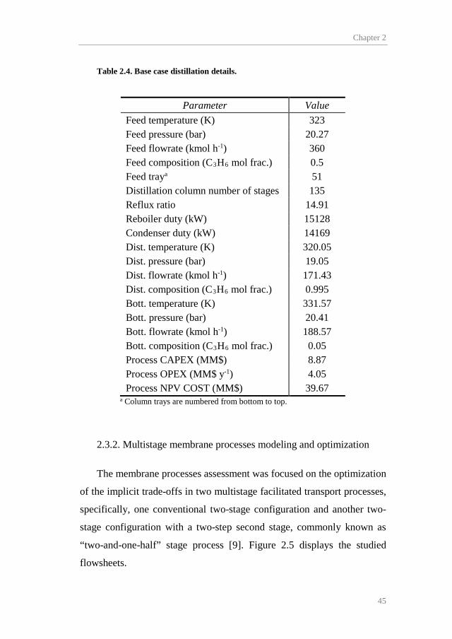
To quantify the potential economic savings, the conventional
distillation was established as base case. The feed stream consists of 360
kmol/h of a liquid propane/propylene equimolar mixture at 323 K and
20.27 bar. The product specifications are 0.995 propylene mole fraction in
the distillate stream (i.e. polymer grade) and 0.95 propane mole fraction in
the bottoms stream. Table 2.4 itemizes the base case details and economics,
which were calculated using the “Guthrie’s Modular Method for Costing
and Sizing” [8].
Chapter 2
45
Table 2.4. Base case distillation details.
Parameter Value Feed temperature (K) 323 Feed pressure (bar) 20.27 Feed flowrate (kmol h-1) 360 Feed composition (C3H6 mol frac.) 0.5 Feed traya 51 Distillation column number of stages 135 Reflux ratio 14.91 Reboiler duty (kW) 15128 Condenser duty (kW) 14169 Dist. temperature (K) 320.05 Dist. pressure (bar) 19.05 Dist. flowrate (kmol h-1) 171.43 Dist. composition (C3H6 mol frac.) 0.995 Bott. temperature (K) 331.57 Bott. pressure (bar) 20.41 Bott. flowrate (kmol h-1) 188.57 Bott. composition (C3H6 mol frac.) 0.05 Process CAPEX (MM$) 8.87 Process OPEX (MM$ y-1) 4.05 Process NPV COST (MM$) 39.67
a Column trays are numbered from bottom to top.
2.3.2. Multistage membrane processes modeling and optimization
The membrane processes assessment was focused on the optimization
of the implicit trade-offs in two multistage facilitated transport processes,
specifically, one conventional two-stage configuration and another two-
stage configuration with a two-step second stage, commonly known as
“two-and-one-half” stage process [9]. Figure 2.5 displays the studied
flowsheets.

Experimental and modeling methods
46
Figure. 2.5. Facilitated transport multistage membrane processes.
In this manner, the complex mixed-integer nonlinear formulations
associated to superstructures could be avoided. Additionally, a
simultaneous optimization of the process and the membrane material (i.e.
carrier load) was possible thanks to the introduction of the previously
developed facilitated transport model.
The membrane modules were modelled as hollow fiber modules,
which is the most adequate configuration for gas separation, featuring high
packing densities and energy efficiency [10–12]. Furthermore, the mass
balances in the membrane modules were described as ordinary differential
F R
P
M1
M2
F R
P
M1
M2M3
A
B
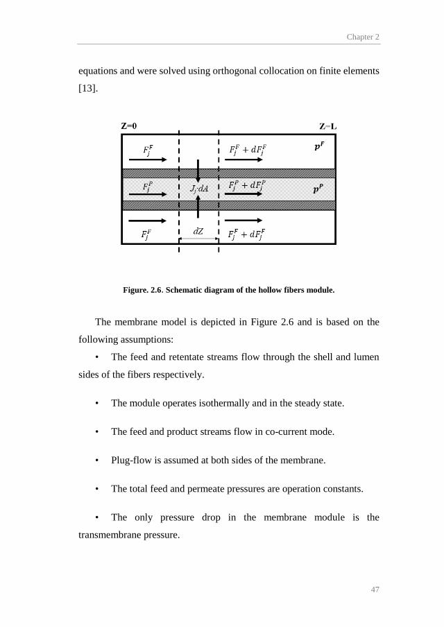
Chapter 2
47
equations and were solved using orthogonal collocation on finite elements
[13].
Figure. 2.6. Schematic diagram of the hollow fibers module.
The membrane model is depicted in Figure 2.6 and is based on the
following assumptions:
• The feed and retentate streams flow through the shell and lumen
sides of the fibers respectively.
• The module operates isothermally and in the steady state.
• The feed and product streams flow in co-current mode.
• Plug-flow is assumed at both sides of the membrane.
• The total feed and permeate pressures are operation constants.
• The only pressure drop in the membrane module is the
transmembrane pressure.

Experimental and modeling methods
48
The component molar flowrates were discretized according to the
following mass balances:
𝑑𝑑𝐹𝐹𝑗𝑗𝐹𝐹(𝑧𝑧) = −𝐽𝐽𝑗𝑗(𝑧𝑧) · 𝑑𝑑𝐴𝐴 (28)
𝑑𝑑𝐹𝐹𝑗𝑗𝑃𝑃(𝑧𝑧) = 𝐽𝐽𝑗𝑗(𝑧𝑧) · 𝑑𝑑𝐴𝐴 (29)
where 𝐹𝐹𝑗𝑗 and 𝐽𝐽 are the molar flowrate and the transmembrane flux of
component j, respectively, and 𝑑𝑑𝐴𝐴 is the fiber outer wall area differential
element. The dimensionless fiber axial length is defined as:
𝑧𝑧̅ =𝑧𝑧𝐿𝐿
𝑧𝑧̅ ∈ [0,1] (30)
where L is the total fiber length. Rearranging terms, the mass balances
(ODEs) and the boundary conditions can now be rewritten as:
𝑑𝑑𝐹𝐹𝑗𝑗𝐹𝐹(𝑧𝑧̅)𝑑𝑑𝑧𝑧̅
= −𝐽𝐽𝑗𝑗(𝑧𝑧̅) · 𝐴𝐴 (31)
𝑑𝑑𝐹𝐹𝑗𝑗𝑃𝑃(𝑧𝑧̅)𝑑𝑑𝑧𝑧̅
= 𝐽𝐽𝑗𝑗(𝑧𝑧̅) · 𝐴𝐴 (32)
𝐹𝐹𝑗𝑗𝐹𝐹|�̅�𝑧=0 = 𝐹𝐹𝑗𝑗𝐹𝐹(𝑧𝑧̅ = 0) (33)
𝐹𝐹𝑗𝑗𝑃𝑃|�̅�𝑧=0 = 0 (34)
The propylene transmembrane flux was described by implementing the
specific model for facilitated transport previously developed. This avoided
the use of a fixed permeability parameter and introduced the carrier
concentration as a decision variable. In this way, the membrane material
and the multistage process could be optimized at the same time.

Chapter 2
49
The ordinary differential equations (Eq. 31-34) were solved as
algebraic equations after discretization through implicit Runge-Kutta
collocation methods using 100 finite elements and 3 internal collocation
points.
The pressure, temperature and composition of the original feed, stream
F in Figure 2.5, were fixed by common refinery specifications [7]. Table
2.5 displays the properties of the propylene/propane mixed stream, the
target product purities and the process constants and constraints.
Table 2.5. Process feed specifications, parameters and constraints.
Parameter Value Feed temperature (K) 323 Feed pressure (bar) 18 Feed flowrate (kmol h-1) 360 Feed composition (C3H6 mole frac.) 0.50 Permeate pressure (bar) 1-18 Required C3H6 purity (xi) ≥ 0.995 Required C3H8 purity (xi) ≥ 0.950 C3H8 permeability (Barrer)a 20 Membrane thickness (µm) 20 Silver loadingb (M) 0-6
a 1 Barrer = 10−10 cm3 (STP) cm cm−2 s−1 cmHg−1. b Silver loading delimited according to the experimentally
studied concentration range [7,10].
Finally, the objective function (NPVC) was calculated as a
combination of OPEX and CAPEX, correcting the operating expenses
according to the time value of money:

Experimental and modeling methods
50
𝑁𝑁𝑃𝑃𝑉𝑉𝐶𝐶 = 𝐶𝐶𝐴𝐴𝑃𝑃𝐸𝐸𝐶𝐶 + 𝑂𝑂𝑃𝑃𝐸𝐸𝐶𝐶 · (1 − (1 + 𝑟𝑟)−𝑇𝑇) 𝑟𝑟⁄ (35)
The compressor expenses were calculated according to the “Guthrie’s
Modular Method for Costing and Sizing “ [8] and the membrane cost was
calculated using the market prices for its constituents and the optimized
composition.
The model constraints accounted for the same propane and propylene
product purities established for the distillation base case.
Once the optimization model was solved, it returned:
• The optimal membrane area of each module.
• The optimal carrier concentration of each membrane.
• The optimal permeate pressure.
• The minimal NPVC to reach the separation specifications.
2.3.3. Hybrid membrane-distillation process modeling and
optimization
In this work, the performance of state-of-the-art membrane materials
to retrofit an existing distillation process was assessed. Taking advantage
of the membranes effectiveness when used as concentrators [14], the
proposed hybrid configuration uses a membrane stage to perform the bulk
separation and the distillation column is left for the final product polishing.
Figure 2.7 displays the proposed hybrid arrangement. Given that this
hybrid process is intended to retrofit an existing distillation column, the
operating costs (OPEX) of the hybrid process were evaluated and

Chapter 2
51
compared with the previously described base case distillation. For this
reason, the same number of equilibrium stages of the benchmark
distillation column was considered in the hybrid configuration.
The design of a membrane/distillation hybrid process involves solving
an optimization problem, driven by the existing compromise between the
membrane total cost and the column operating expenses.
Figure. 2.7. Schematic diagram of the hybrid process.
In this case-study, the mathematical model for the membrane separator
described before was implemented. Since the performance of diverse
membrane materials was investigated, both propane and propylene
transmembrane fluxes were calculated considering the permeability of
each species as a material constant. For this reason, a selection of
membrane materials to represent the current industrially attractive

Experimental and modeling methods
52
possibilities for a hybrid process was proposed, including the facilitated
transport membranes developed in this PhD thesis. Table 2.6 summarizes
the selected membranes features.
Table 2.6. Separation performance of the selected membranes.
Membrane C3H6
Permeance (GPUa)
C3H6 Selectivity Source
CMS 42 23 [15] ZIF-8 90 50 [16] ZIF-8/ZIF-67/ZIF-8 111 210 [17] PVDF-HFP/BMImBF4/AgBF4 40 150 [18] 6FDA-TeMPD 37b 8.6 [19] EC 7 7 [20]
a 1 GPU=3.35x10⁻¹⁰ mol/m2 Pa s b Calculated from reported permeability assuming 1 µm thickness
Finally, in a second part of this case-study, the permeability-selectivity
trade-off exhibited by membrane materials was assessed, introducing an
updated trade-off expression in the optimization model. In this way, a
wider insight into state-of-the-art membrane performance can be provided.
The model for the distillation column was adapted from the work of
Lang and Biegler [21]. A complete description can be found in the original
source, here a brief description is presented. Figure 2.8 provides a
schematic representation of the modeling strategy.

Chapter 2
53
Figure. 2.8. Schematic diagram of the Distributed Stream-Tray Optimization
Method (DSTO) and detail of reflux stream DDF.
In order to avoid discrete decision variables, this model uses
differentiable distribution functions (DFF) for the feed, reflux and
intermediate product streams (if present), in the form:
𝑑𝑑𝑖𝑖 =𝑠𝑠𝑥𝑥𝑠𝑠 �− �𝑖𝑖 − 𝑁𝑁𝑐𝑐
𝜎𝜎 �2�
∑ 𝑠𝑠𝑥𝑥𝑠𝑠 �− �𝑘𝑘 − 𝑁𝑁𝑐𝑐𝜎𝜎 �
2�𝑘𝑘
𝑖𝑖,𝑘𝑘 ∈ 𝐼𝐼 (36)
which corresponds to the discretization of a Gaussian distribution with
mean 𝑁𝑁𝑐𝑐 and standard deviation σ. Thus, using DDFs, the feed and reflux
streams can be distributed to all trays:
𝐸𝐸𝑖𝑖 = 𝐸𝐸 · 𝑠𝑠𝑖𝑖 (37)
𝑅𝑅𝑖𝑖 = 𝑅𝑅 · 𝑟𝑟𝑖𝑖 (38)
where 𝐸𝐸𝑖𝑖 and 𝑅𝑅𝑖𝑖 are the feed and reflux flowrates entering into the i-
th tray, 𝑠𝑠𝑖𝑖 and 𝑟𝑟𝑖𝑖 are the corresponding differentiable distribution functions
…
F1
F2 P
DR
B
Ni+1
i-1
RDry trays D

Experimental and modeling methods
54
and 𝐸𝐸 and 𝑅𝑅 and are the total feed and reflux streams, respectively. Once
the feed and reflux streams are defined through a DDF, the model uses the
conventional MESH equations (material balances, equilibrium, summation
and enthalpy balances) to formulate the distillation model. As described in
[21] the model is also capable of calculating the number of trays by
relaxing the equilibrium equations in the MESH equations so that the liquid
phase disappears. This modification of the MESH equations allows dry
trays to appear without pressure drop in the non-existing trays space above
the reflux insertion point. The optimization model then chooses the column
operation with the optimal number of dry trays, which translates to the
optimum number of trays required.
The vapor-liquid equilibrium was introduced using the K-value charts
for C3 mixtures [22]. These charts are constructed upon experimental data,
later displayed in nomograms. To allow its implementation in computer
calculations, a corresponding states type approach has been reported in the
bibliography [23]. This approach considers the equilibrium constant value
as a function of pressure and temperature exclusively, neglecting the
effects of composition. This assumption is valid for propane/propylene
mixtures at the pressure and temperature range covered in this study.
The optimization objective was to minimize the total operating costs.
Here it was included:
• Membrane depreciation.
• Permeate and retentate recompression.
• Reboiler and condenser duties.

Chapter 2
55
The membrane depreciation was easily calculated as the membrane
cost divided by the membrane lifetime, thus obtaining the annualized cost.
The compressors, reboiler and condenser annualized operating expenses
were calculated converting the resulting duties with the market price of the
respective utilities.
Table 2.7 displays the properties of the propylene/propane feed stream,
the target product purities and the process constants and constraints.
Table 2.7. Process feed specifications, parameters and constraints.
Parameter Value Feed temperature (K) 325 Feed pressure (bar) 18 Feed flowrate (kmol h-1) 360 Feed composition (C3H6 mol frac.) 0.5 Membrane feed side pressure (bar) 18 Membrane permeate side pressure (bar) 1 Distillation column number of stages 135 Distillate purity, 𝑥𝑥𝐶𝐶3𝐻𝐻6,𝑚𝑚𝑖𝑖𝑚𝑚
𝐷𝐷 ≥ 99.5 Bottoms purity, 𝑥𝑥𝐶𝐶3𝐻𝐻8,𝑚𝑚𝑖𝑖𝑚𝑚
𝐵𝐵 ≥ 95.0
Finally, the model constraints accounted for the same propane and
propylene product purities established for the distillation base case.
Once the solver was run, it provided:
• The minimal operating expenses (and the partial contributions).
• The optimal membrane area.
• The optimal reflux ratio.
Experimental and modeling methods
56
• The optimal feed tray locations.
2.3.4. Optimization software
The optimization models of both case-studies were implemented in the
General Algebraic Modelling System (GAMS) and solved using the
multistart heuristic algorithm OQNLP on a 3.40 GHz Intel® CoreTM i7-
3770 processor. CONOPT has been used as local NLP solver for OQNLP
with a time limit of 3000 seconds and a maximum of 3000 trial points and
3000 CONOPT calls. The GAMS code of both case-studies can be
consulted in Appendices A.3 and A.4.
Chapter 2
57
2.4. References
[1] M. Fallanza, Progress in the recovery of gaseous olefins. The
combined role of membranes, facilitated transport and ionic liquids,
Universidad de Cantabria, 2013.
[2] T.C. Merkel, R. Blanc, I. Ciobanu, B. Firat, A. Suwarlim, J. Zeid,
Silver salt facilitated transport membranes for olefin/paraffin
separations: Carrier instability and a novel regeneration method, J.
Memb. Sci. 447 (2013) 177–189.
[3] R.D. Noble, Generalized microscopic mechanism of facilitated
transport in fixed site carrier membranes, J. Memb. Sci. 75 (1992)
121–129.
[4] A. Ortiz, A. Ruiz, D. Gorri, I. Ortiz, Room temperature ionic liquid
with silver salt as efficient reaction media for propylene/propane
separation: Absorption equilibrium, Sep. Purif. Technol. 63 (2008)
311–318.
[5] M. Fallanza, A. Ortiz, D. Gorri, I. Ortiz, Experimental study of the
separation of propane/propylene mixtures by supported ionic liquid
membranes containing Ag+–RTILs as carrier, Sep. Purif. Technol.
97 (2012) 83–89.
[6] R. Zarca, A. Ortiz, D. Gorri, I. Ortiz, A practical approach to fixed-
site-carrier facilitated transport modeling for the separation of
propylene/propane mixtures through silver-containing polymeric
membranes, Sep. Purif. Technol. 180 (2017) 82–89.
[7] W.L. Luyben, Dynamic simulation of flooded condensers, Chem.
Eng. Res. Des. 118 (2017) 12–20.
[8] L.T. Biegler, I.E. Grossmann, A.W. Westerberg, Systematic
Methods of Chemical Process Design, Prentice Hall PTR, New
Jersey, 1997.

Experimental and modeling methods
58
[9] R.W. Baker, Membrane Technology and Applications, 3rd Editio,
Wiley, Chichester, 2012.
[10] D.C. Nymeijer, T. Visser, R. Assen, M. Wessling, Composite
hollow fiber gas-liquid membrane contactors for olefin/paraffin
separation, Sep. Purif. Technol. 37 (2004) 209–220.
[11] D.T. Coker, B.D. Freeman, G.K. Fleming, Modeling
multicomponent gas separation using hollow-fiber membrane
contactors, AIChE J. 44 (1998) 1289–1302.
[12] C.Y. Pan, Gas separation by high‐flux, asymmetric hollow‐fiber
membrane, AIChE J. 32 (1986) 2020–2027.
[13] J.I. Marriott, E. Sørensen, I.D.L. Bogle, Detailed mathematical
modeling of membrane modules, Comput. Chem. Eng. 25 (2001)
693–700.
[14] R. Spillman, Economics of gas separation membrane processes, in:
R.D. Noble, S.A. Stern (Eds.), Membr. Sep. Technol. Princ. Appl.,
Elsevier Science, 1995.
[15] M. Xiaoli, Y.S. Lin, Ultrathin Carbon Molecular Sieve Membrane
for Propylene/Propane Separation, AIChE J. 62 (2016) 491–499.
[16] Y. Pan, T. Li, G. Lestari, Z. Lai, Effective separation of
propylene/propane binary mixtures by ZIF-8 membranes, J. Memb.
Sci. 390–391 (2012) 93–98.
[17] H.T. Kwon, H.K. Jeong, A.S. Lee, H.S. An, J.S. Lee,
Heteroepitaxially Grown Zeolitic Imidazolate Framework
Membranes with Unprecedented Propylene/Propane Separation
Performances, J. Am. Chem. Soc. 137 (2015) 12304–12311.
[18] R. Zarca, A. Ortiz, D. Gorri, I. Ortiz, Generalized predictive
modeling for facilitated transport membranes accounting for fixed
and mobile carriers, J. Memb. Sci. 542 (2017) 168–176.

Chapter 2
59
[19] K. Okamoto, K. Noborio, J. Hao, K. Tanaka, H. Kita, Permeation
and separation properties of polyimide membranes to 1, 3-
butadiene and n-butane, J. Memb. Sci. 134 (1997) 171–179.
[20] A. Ito, S. ‐T Hwang, Permeation of propane and propylene through
cellulosic polymer membranes, J. Appl. Polym. Sci. 38 (1989) 483–
490.
[21] Y.D. Lang, L.T. Biegler, Distributed stream method for tray
optimization, AIChE J. 48 (2002) 582–595.
[22] E.G. Scheibel, F.J. Jenny, Nomographs for Enthalpies of Pure
Hydrocarbons and Their Mixtures, Ind. Eng. Chem. 37 (1945) 990–
995.
[23] Dimitrios Tassios, Applied Chemical Engineering
Thermodynamics, 1993rd ed., Springer, 1993.


Chapter 3 Results summary
Abstract
In this chapter, the main results obtained during the PhD thesis are
summarized. In the first place, the experimental results regarding the
membrane characterization though spectroscopic, thermogravimetric and
microscopy techniques are discussed, paying special attention to the
influence and relationships of the membrane structure with the resultant
gas transport mechanisms. Then, gas permeation results obtained through
time-lag and continuous-flow techniques are presented, exploring the
influence of the most relevant operating conditions on the membrane
performance and assessing the facilitated transport mathematical model
fitting. Finally, the main results on process design and optimization of
hybrid and multistage membrane processes are presented. This allowed
evaluating the potential of the proposed membranes to intensify the
propane/propylene separation process.

Results summary
62
3.1. Membrane characterization
In this section, the results of the membrane characterization are
presented. SEM and EDX techniques were used to study the membrane
morphology and the silver distribution within the facilitated transport
membrane, respectively. The thermogravimetric measurements allowed
determining the potential water uptake, which is related to the feed
humidity influence on the membrane performance. Finally, the
spectroscopic techniques (FTIR, Raman and XPS) revealed the
interactions between the membrane components, which explain the nature
of the facilitated transport mechanisms occurring inside the membrane.
3.1.1. SEM-EDX
Figure 3.1 shows the cross-section and surface of PVDF-HFP, PVDF-
HFP/BMImBF4 and PVDF-HFP/BMImBF4/AgBF4 membranes.
Figure. 3.1. Cross-section and surface morphology of: A) PVDF-HFP membrane B)
PVDF-HFP/BMImBF4 membrane, C) PVDF-HFP/BMImBF4/AgBF4 (5.23 mol/l).
A B C
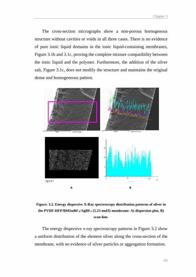
Chapter 3
63
The cross-section micrographs show a non-porous homogenous
structure without cavities or voids in all three cases. There is no evidence
of pure ionic liquid domains in the ionic liquid-containing membranes,
Figure 3.1b and 3.1c, proving the complete mixture compatibility between
the ionic liquid and the polymer. Furthermore, the addition of the silver
salt, Figure 3.1c, does not modify the structure and maintains the original
dense and homogeneous pattern.
Figure. 3.2. Energy dispersive X-Ray spectroscopy distribution patterns of silver in
the PVDF-HFP/BMImBF4/AgBF4 (5.23 mol/l) membrane: A) dispersion plot, B)
scan-line.
The energy dispersive x-ray spectroscopy patterns in Figure 3.2 show
a uniform distribution of the element silver along the cross-section of the
membrane, with no evidence of silver particles or aggregation formation.
A B

Results summary
64
3.1.2. Thermogravimetric analysis (TGA)
The thermogravimetric curves of PVDF-HFP, PVDF-HFP/AgBF4 and
PVDF-HFP/BMImBF4/AgBF4 membranes are displayed in Figure 3.3.
300 400 500 600 700 8000
10
20
30
40
50
60
70
80
90
100
% In
itial W
eigh
t
PVDF-HFP PVDF-HFP/AgBF4
PVDF-HFP/BMImBF4/AgBF4
T (K)
Figure. 3.3. TGA curves of the studied membranes.
The membrane samples were vacuum dried at 30 mbar and 298 K for
24 hours after casting to completely remove the remaining solvent. Prior
to testing the samples were exposed to ambient moisture (~80% RH at
room temperature) for 24 hours. In this manner, any water loss appearing
at the beginning of the temperature ramp can be attributed to water
evaporation. According to Figure 3.3, the pure polymer membrane exhibits
no weight loss until it reaches its degradation temperature around 680 K,
which reveals no water uptake. This is in good agreement with the
hydrophobic nature of the fluoropolymer [1]. However, Figure 3.3 shows
prominent mass losses of the silver-containing membranes in the 300-436

Chapter 3
65
K temperature range. Thus, it can be concluded that the addition of the
AgBF4 salt to the membrane composition dramatically changes the nature
of the facilitated transport membranes due to its high hygroscopicity,
which results in water uptakes of around 25 wt.% when exposed to moist
conditions. Moreover, the ionic liquid-containing membrane features a
similar water uptake as the PVDF-HFP/AgBF4 membrane, this is because
BMImBF4 is also a hygroscopic substance. Finally, the PVDF-
HFP/BMImBF4/AgBF4 membrane starts degrading at 625 K, slightly
below the pristine PVDF-HFP and PVDF-HFP/AgBF4 membranes. This
is caused by the influence of the ionic liquid on the polymer structure,
which yields a multistep decomposition mechanism, as reported by Shalu
et al. [2].
3.1.3. Fourier transform infrared spectroscopy (FTIR)
Figure 3.4 shows the polymer CF2 symmetrical stretching band of
PVDF-HFP, PVDF-HFP/AgBF4 and PVDF-HFP/BMImBF4/AgBF4
membranes. The CF2 peak of the pure polymer appears in the 1178 cm-1
band. After incorporation of the silver salt, the stretching band shifted to
1174 and 1172 cm-1 in the PVDF-HFP/AgBF4 and PVDF-
HFP/BMImBF4/AgBF4 respectively. This shift to lower wavelength
indicates a weakening of the C-F bond caused by the interaction of silver
cations with the fluorine atoms of the fluoropolymer, which is the basis of
the fixed site carrier transport mechanism. This phenomenon has been
previously observed by Chang and Kang [3] using FTIR on PVDF-
HFP/HBF4 polymer electrolytes.

Results summary
66
Figure. 3.4. FTIR spectra of the studied membranes.
3.1.4. RAMAN spectroscopy
Raman spectroscopy was used to analyze the regions of the
BF4- stretching bands in the pure AgBF4, and the silver-containing
membranes. Figure 3.5 shows the BF4- stretching band region of PVDF-
HFP/AgBF4 and PVDF-HFP/BMImBF4/AgBF4 membranes. The
symmetric stretching mode of BF4- has been previously reported at 774
cm-1 in the pure AgBF4 [4]. However, the spectrum in Figure 3.5a shows
a wavenumber shift to 767 cm-1 when the silver is added to the polymer.
According to previous studies, this wavenumber corresponds to free ions
[5,6], which means that this change in the Raman spectra is due to well-
dissociated Ag+ cations interacting with the PVDF-HFP backbone.
Furthermore, this wavenumber shift from 774 to 767 cm-1 is still
observable after addition of the ionic liquid BMImBF4, Figure 3.5b. As the
1220 1200 1180 1160 1140 1120
1172
1174
Wavenumber (cm-1)
PVDF-HFP/BMImBF4/AgBF4
PVDF-HFP/AgBF4
PVDF-HFP
1178
Chapter 3
67
BF4- stretching band also appears at 774 cm-1 in the pure ionic liquid [6],
this shift suggests that the ionic liquid is also interacting with the Ag+
cations and, to a certain extent, with the polymer backbone, as reported by
Fallanza et al. [7].
3.1.5. X-ray photoelectron spectroscopy (XPS)
X-ray photoelectron spectroscopy was used to expand the knowledge
on membrane structure and silver degradation. The Ag 3d regions of the
XPS spectra can confirm the interactions between the silver cations and the
polymer fluorine atoms. Figure 3.6 shows the XPS spectra of a PVDF-
HFP/BMImBF4/AgBF4 composite membrane after a long term permeation
experiment (110 days). Table 3.1 summarizes the two silver species
observable after signal deconvolution. The Ag 3d5/2 band of pure AgBF4
has been previously reported at 369.2 eV. However, in the composite
membrane, the binding energy shifted to 368.47 eV. This reduction in the
photoelectron binding energy is caused by the coordination between the
silver atoms and the polymer backbone as demonstrated by Kim et al. [8],
who found the same phenomenon for several AgBF4/polymer blends.
Additionally, a second silver species (Ag 3d5/2=368.26 Ag 3d3/2=374.25)
is associated with the presence of metallic silver [9], presumably due to the
silver reduction caused by the long term permeation test.

Results summary
68
Figure. 3.5. Raman spectra of A) PVDF-HFP /AgBF4 and B) PVDF-
HFP/BMImBF4/AgBF4 membrane.
750 760 770 780
767
Raman shift (cm-1)
A
740 750 760 770 780 790
B
767
Raman shift (cm-1)
767
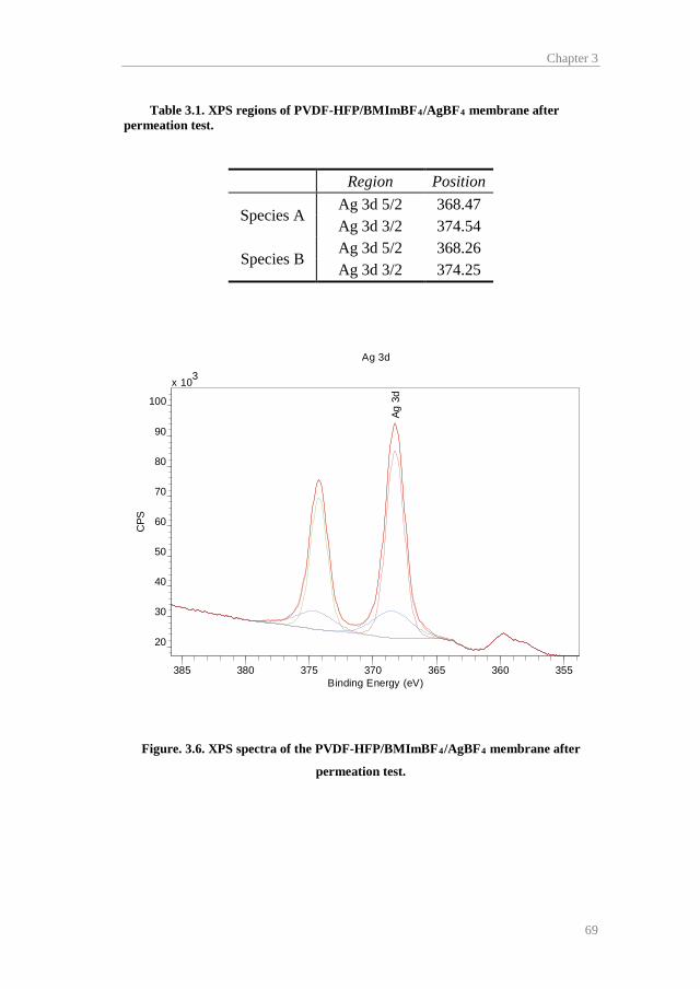
Chapter 3
69
Table 3.1. XPS regions of PVDF-HFP/BMImBF4/AgBF4 membrane after permeation test.
Region Position
Species A Ag 3d 5/2 368.47 Ag 3d 3/2 374.54
Species B Ag 3d 5/2 368.26 Ag 3d 3/2 374.25
Figure. 3.6. XPS spectra of the PVDF-HFP/BMImBF4/AgBF4 membrane after
permeation test.
CasaXPS (This string can be edited in CasaXPS.DEF/PrintFootNote.txt)
Ag 3d
Ag 3
dx 103
20
30
40
50
60
70
80
90
100
CPS
385 380 375 370 365 360 355Binding Energy (eV)

Results summary
70
3.2. Gas permeation and mathematical modeling
In this section, the results of the gas permeation experiments and the
mathematical model fitting are discussed. First, the results of time-lag
experiments with pure gases are presented. These experiments allowed to
determine the gas transport properties of pristine PVDF-HFP and PVDF-
HFP/BMImBF4 membranes. Later, continuous-flow experiments with
synthetic gas mixtures were performed to study the separation performance
of the facilitated transport membranes, assessing the influence of the most
important operating conditions (temperature, feed pressure and membrane
composition). Additionally, the fitting of the developed mathematical
model to the experimental data is reported in this section. Finally, the
results of the long-term permeation and the permeation experiments with
industrial gas mixtures are discussed.
3.2.1. Time-lag permeation
The experimental diffusivity, solubility and permeability values of
propane and propylene in PVDF-HFP and PVDF-HFP/BMImBF4 (80/20
wt.%) at different temperatures were obtained using the time-lag
technique. Table 3.2 summarizes the experimental values of diffusivity,
solubility and permeability of propane and propylene in PVDF-HFP
membranes at different temperatures.
The results in Table 3.2 show a significant increase in permeability
with increasing temperature. Given that the physical solubility slightly
decreases, this effect of the temperature in the final permeability value is
mainly caused by the influence of the diffusivity.
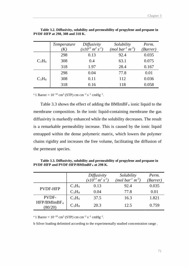
Chapter 3
71
Table 3.2. Diffusivity, solubility and permeability of propylene and propane in PVDF-HFP at 298, 308 and 318 K.
Temperature (K)
Diffusivity (x1013 m2 s-1)
Solubility (mol bar-1 m-3)
Perm. (Barrer)
C3H6 298 0.13 92.4 0.035 308 0.4 63.1 0.075 318 1.97 28.4 0.167
C3H8 298 0.04 77.8 0.01 308 0.11 112 0.036 318 0.16 118 0.058
a 1 Barrer = 10−10 cm3 (STP) cm cm−2 s−1 cmHg−1.
Table 3.3 shows the effect of adding the BMImBF4 ionic liquid to the
membrane composition. In the ionic liquid-containing membrane the gas
diffusivity is markedly enhanced while the solubility decreases. The result
is a remarkable permeability increase. This is caused by the ionic liquid
entrapped within the dense polymeric matrix, which lowers the polymer
chains rigidity and increases the free volume, facilitating the diffusion of
the permeant species.
Table 3.3. Diffusivity, solubility and permeability of propylene and propane in PVDF-HFP and PVDF-HFP/BMImBF4 at 298 K.
Diffusivity (x1013 m2 s-1)
Solubility (mol bar-1 m-3)
Perm. (Barrer)
PVDF-HFP C3H6 0.13 92.4 0.035 C3H8 0.04 77.8 0.01
PVDF-HFP/BMImBF4
(80/20)
C3H6 37.5 16.3 1.821
C3H8 20.3 12.5 0.759
a 1 Barrer = 10−10 cm3 (STP) cm cm−2 s−1 cmHg−1.
b Silver loading delimited according to the experimentally studied concentration range .

Results summary
72
However, these results confirm that the separation of
propane/propylene mixtures by means of solution-diffusion mechanisms
in PVDF-HFP membranes is ineffective due to the low permselectivity
achieved.
The diffusivity and the physical solubility of propane and propylene in
the polymer matrix are later used in the mathematical description of gas
transport in the facilitated transport membranes, for this reason, the
determination of these parameters is an important step for the mathematical
modeling.
3.2.2. Gas-mixture permeation and model fitting
Figure 3.7 shows the propylene transmembrane flux in PVDF-
HFP/AgBF4 and PVDF-HFP/BMImBF4/AgBF4 with increasing feed
partial pressure. As the partial pressure gradient offers the driving force for
the separation process, it has a direct effect on the propylene flux.
Nonetheless, the composite membrane performs high olefin fluxes even at
the lower assessed partial pressures.
On the other hand, the effect of the temperature increase on the
propylene flux is also observable in Figure 3.7. Higher temperatures favor
the thermal rearrangements of the polymer chains, enhancing the fixed site
carrier transport. Additionally, the diffusion of the gaseous species and the
organometallic complex is increased with higher temperatures. As a result
the propylene flux increases in both membranes. All these effects hinder
the negative influence on the complexation equilibrium constant and the
lower gas solubility caused at higher temperatures.

Chapter 3
73
Finally, the addition of the ionic liquid, which gives rise to the mobile
carrier transport mechanism, has a major effect on the propylene transport,
as can be concluded by comparing the propylene transmembrane flux with
and without BMImBF4.
Regarding the separation performance, the high propylene fluxes
combined with very low propane fluxes, typically below 1x10⁻⁵ mol m-2 s-
1, yield selectivity values of around 150.
The mathematical model prediction is noted with black lines in Figure
3.7, and suggests a good fitting of the calculated values. These results
demonstrate the model capability to predict the propylene transmembrane
flux in the studied range of the variables.
Figure. 3.7. Propylene experimental flux and model prediction in PVDF-HFP/AgBF4
(5.53 mol/l) and PVDF-HFP/BMImBF4/AgBF4 (5.23 mol/l) with increasing partial
pressure and 293-303K.
Regarding the propane flux, it can be easily predicted through the
solution-diffusion theory using the experimentally obtained permeability.
0.4 0.6 0.8 1.0 1.2 1.4 1.6
2
4
6
8
10
12
PVDF-HFP/AgBF4 293 K PVDF-HFP/AgBF4 303 K PVDF-HFP/BMImBF4/AgBF4 293K PVDF-HFP/BMImBF4/AgBF4 303K
J C 3H
6 (x1
04 mol
m-2 s
-1)
P C3H6 (bar)

Results summary
74
In order to determine the separation behavior of the composite
membranes over an extended period of time, a 110 days long-term
permeation test on a PVDF-HFP/BMImBF4/AgBF4 membrane was
performed. Furthermore, the effect of the feed gas humidity was assessed.
Figure 3.8 shows the propylene and propane transmembrane flux during
the experiment, which is divided into five sections (I-V) accounting for the
relative humidity conditions.
Figure. 3.8. Long term permeation experiment of a PVDF-HFP/BMImBF4/AgBF4 (4
mol/l) composite membrane at 298 K and 1.2 bar feed total pressure (C3H8/C3H6
50:50) under different relative humidity conditions.
A characteristic feature of these facilitated transport membranes under
dry conditions is a sharp decrease of the permeation flux in the first
operating hours ostensibly caused by the rapid loss of water and residual
solvent by evaporation. To explore this, the humidity was kept at saturation
at the beginning of the test (section I) and, subsequently, no flux decay was
0 10 20 30 40 50 60 70 80 90 100 110 1201E-7
1E-6
1E-5
1E-4
1E-3
0.01
VIVIIIIIRH=100% RH=25%RH=50%RH=0%
C3H6
C3H8
Flux
C3H
X (m
ol m
-2 s
-1)
Time (days)
RH=100%I
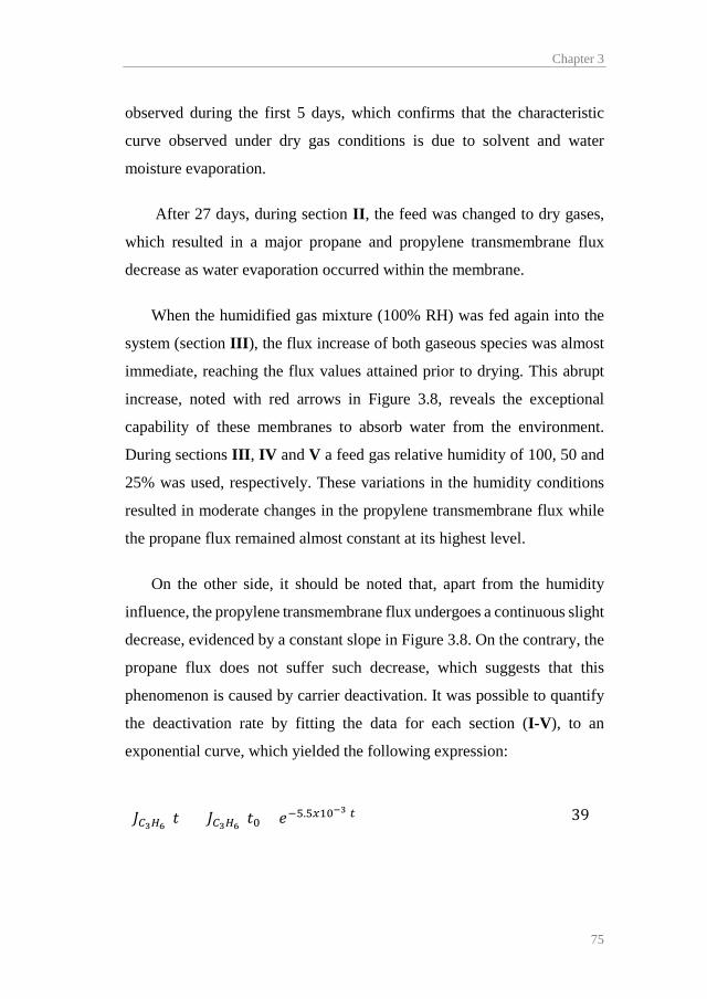
Chapter 3
75
observed during the first 5 days, which confirms that the characteristic
curve observed under dry gas conditions is due to solvent and water
moisture evaporation.
After 27 days, during section II, the feed was changed to dry gases,
which resulted in a major propane and propylene transmembrane flux
decrease as water evaporation occurred within the membrane.
When the humidified gas mixture (100% RH) was fed again into the
system (section III), the flux increase of both gaseous species was almost
immediate, reaching the flux values attained prior to drying. This abrupt
increase, noted with red arrows in Figure 3.8, reveals the exceptional
capability of these membranes to absorb water from the environment.
During sections III, IV and V a feed gas relative humidity of 100, 50 and
25% was used, respectively. These variations in the humidity conditions
resulted in moderate changes in the propylene transmembrane flux while
the propane flux remained almost constant at its highest level.
On the other side, it should be noted that, apart from the humidity
influence, the propylene transmembrane flux undergoes a continuous slight
decrease, evidenced by a constant slope in Figure 3.8. On the contrary, the
propane flux does not suffer such decrease, which suggests that this
phenomenon is caused by carrier deactivation. It was possible to quantify
the deactivation rate by fitting the data for each section (I-V), to an
exponential curve, which yielded the following expression:
𝐽𝐽𝐶𝐶3𝐻𝐻6(𝑡𝑡) = 𝐽𝐽𝐶𝐶3𝐻𝐻6(𝑡𝑡0) · 𝑒𝑒−5.5𝑥𝑥10−3·𝑡𝑡 (39)

Results summary
76
where 𝐽𝐽𝐶𝐶3𝐻𝐻6(𝑡𝑡0) is the initial propylene transmembrane flux at a given
membrane composition, temperature, pressure and relative humidity
conditions and the time t is introduced in days. This expression allows for
membrane lifetime calculation if a minimum required performance is
established.
Finally, combining a mathematical expression for the drying curve
(Figure 3.8 section II) with the propylene flux at each relative humidity, it
was possible to obtain a fitting curve for the propylene transmembrane flux
as a function of the relative humidity (Eq. 40), Figure 3.9.
𝐽𝐽𝐶𝐶3𝐻𝐻6(𝑅𝑅𝑅𝑅) = 5.82𝑥𝑥10−5𝑅𝑅𝑅𝑅0.49 (40)
Figure 3.9 evidences a sharp increase in the propylene flux with the
relative humidity for RH<10% and a smooth increase after that value (dash
line in Figure 3.9). A similar trend was reported by Catalano et al. [10] for
oxygen and nitrogen in PFSI membranes.
Finally, Table 3.4 displays the permeability and selectivity values of
the facilitated transport membrane for each relative humidity condition.
The humidification of the feed gases produces major changes in the
membrane performance, reducing the selectivity and increasing the
permeability of both the olefin and the paraffin. This is a characteristic
effect of water vapor-induced swelling [11,12]. The enlargement of the
polymer free volume caused by the water uptake increases the diffusivity
of the gaseous species and the propylene-silver complex, which leads to
remarkable permeability values but at the expense of membrane
selectivity.

Chapter 3
77
Figure. 3.9. Experimental data and mathematical regression for the dependency of
the propylene transmembrane flux on the relative humidity.
Table 3.4. Average permeability and selectivity values of the PVDF-HFP/BMImBF4/AgBF4 membrane for each relative humidity during the long-term permeation test.
RH (%)
P C3H8 (Barrer)a
P C3H6
(Barrer)a α C3H6/C3H8
(-) 0 1.2 172 144
25 97.3 1032 11 50 107.6 1666 16
100 106.5 2555 24
a 1 Barrer = 10−10 cm3 (STP) cm cm−2 s−1 cmHg−1.
0 20 40 60 80 1001E-5
1E-4
1E-3
Model Experimental
Flux
C3H
6 (m
ol m
-2 s
-1)
RH (%)

Results summary
78
3.2.3. Industrial gas mixture permeation
Figure 3.10 shows the facilitated transport membrane performance
when the feed consists of a real propane/propylene mixture compared with
a synthetic gas mixture. The industrial gas mixture is the product stream of
a fluid catalytic cracking unit and its composition is displayed in Table 2.1.
It mostly consists of a propane/propylene mixture (25:75) containing minor
quantities of light paraffins and olefins.
Given that both feeds differ in composition, permeability, which is
normalized by the partial pressure gradient, has been plotted instead of the
transmembrane flux. Both permeation experiments have been performed
under dry conditions to simulate refinery conditions, hence, both suffer the
characteristic permeability decrease due to solvent and water evaporation
in the first hours of operation. Since the propylene transmembrane flux is
similar in both cases, Figure 3.10 evidences that the membrane
performance is not affected by known contaminant trace components
potentially present in industrial streams (i.e. acetylene, hydrogen sulfide
and hydrogen [13]) during the experiment extent.
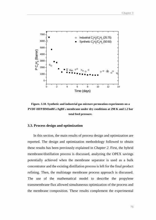
Chapter 3
79
Figure. 3.10. Synthetic and industrial gas mixture permeation experiments on a
PVDF-HFP/BMImBF4/AgBF4 membrane under dry conditions at 298 K and 1.2 bar
total feed pressure.
3.3. Process design and optimization
In this section, the main results of process design and optimization are
reported. The design and optimization methodology followed to obtain
these results has been previously explained in Chapter 2. First, the hybrid
membrane/distillation process is discussed, analyzing the OPEX savings
potentially achieved when the membrane separator is used as a bulk
concentrator and the existing distillation process is left for the final product
refining. Then, the multistage membrane process approach is discussed.
The use of the mathematical model to describe the propylene
transmembrane flux allowed simultaneous optimization of the process and
the membrane composition. These results complement the experimental
0 2 4 6 8 10 12 14
0
1000
2000
3000
4000
5000
6000
7000 Industrial C3H8/C3H6 (25:75) Synthetic C3H8/C3H6 (50:50)
P C 3H
6 (Ba
rrer)
Time (days)

Results summary
80
study on membrane performance, aiming at the global objective of
assessing the role of facilitated transport membranes in the intensification
of propylene/propane separation processes.
3.3.1. Membrane/distillation hybrid process
The hybrid process optimization allowed calculating the operating
expenses reduction achieved by retrofitting an existing distillation column
with a membrane contactor. In the first place, several state-of-the-art
membrane materials were studied for its implementation in the hollow
fiber configuration, including the PVDF-HFP/BMImBF4/AgBF4
composite membranes developed by the research group. Next, the current
membrane upper bound was introduced in the model to study the desirable
permeability/selectivity combination of a hypothetically optimal
membrane material. Additionally, the impact of the membrane cost on the
economic evaluation was assessed.
The purity constraints introduced in all calculations considered a
propylene purity of 99.5 mol.% and a propane purity of 95.0 mol.% in the
head and tail streams of the distillation column, respectively.
Table 3.5 displays the resultant membrane area, reflux ratio and
potential savings derived from the implementation of each selected
membrane material in a hybrid configuration. The highly permeable and
highly selective zeolitic imidazolate frameworks (ZIFs), carbon molecular
sieves (CMS) and facilitated transport membranes (membranes A-D) can
potentially reduce the operating expenses by around 30 to 55%. In addition,
advanced polyimides, as 6FDA-TeMPD (E), which provide high
permeance but moderate selectivity, are still capable of reducing the total
operating costs “TOC” by 18%. Finally, the cellulosic membrane (F), due

Chapter 3
81
to its low permeance and selectivity, achieves a total operation costs
reduction of around 10%.
Table 3.5. Membrane/distillation hybrid process optimization results.
ID Membrane Area (x103 m2) Reflux
TOC Savings
(%) - None - 14.9 0 A ZIF8 / ZIF67/ZIF8 2.8 4.5 56.2 B PVDF-HFP/AgBF4/BMImBF4 7.4 5.3 50.3 C ZIF 8 2.9 7.4 38.3 D 6FDA-based polyimide CMS 5.8 8.7 29.2 E 6FDA-TeMPD 5.3 10.5 17.6 F EC 23.2 11.2 9.9
The operating expenses reduction due to the implementation of a
hollow fiber module in series is clearly related to the decrease in the
required reflux ratio for a given product quality. Although the reboiler and
condenser duties are very similar, the use of steam requires that more than
95% of the base case operating costs are generated by the reboiler. Figure
3.11 unfolds the total operating expenses for each case. As expected, the
membrane module helps reducing the required reflux ratio, decreasing the
steam supply to the reboiler and its associated cost. It is worth noting that,
despite this reduction, the reboiler operating cost is still the largest
contribution to the total operating costs, while the condenser and retentate
compressor operating costs are almost negligible.

Results summary
82
Figure. 3.11. Disaggregated operating costs for each case. A-F defined in Table 3.5.
Since the hybrid configuration may become uncompetitive compared
to the conventional distillation depending on the membrane unitary cost, a
sensitivity analysis of the optimum solutions was performed. Figure 3.12
displays the total operating cost variation for each membrane with
increasing membrane prices up to 200$/m2. In all cases, with the exception
of the cellulosic membrane (F), the optimal configuration does not vary
significantly, and the resultant TOC increase is proportional to the optimal
membrane area. On the other hand, the cellulosic membrane hybrid
configuration, due to the large area required, is not suitable for replacing
the base case distillation when the membrane cost exceeds ~100$/m2, and
consequently, the membrane module has been removed during the
optimization run.
None A B C D E F1
2
3
4
5
Expe
nses
(MM
$/y)
Membrane ID
Retentate compressor Permeate compressor Membrane Condenser Reboiler

Chapter 3
83
Figure. 3.12. Effect of the membrane cost on optimal TOC for the studied
membranes.
This analysis reveals a remarkable range of suitability for medium to
high performance membrane materials when implemented in a hybrid
configuration, regarding the membrane production cost.
An interesting point when dealing with membranes is the trade-off
existing between selectivity and gas permeability, which is limited by the
upper-bound in the Robeson plot. By introducing the Robeson plot upper-
bound expression in the optimization model we can explore the optimal
permeability and selectivity values of a hypothetically optimal membrane
material, given the membranes state-of-the-art [14,15]. Figure 3.13
represents an updated Robeson plot for propane/propylene mixtures.
0 20 40 60 80 100 120 140 160 180 200 2200
1
2
3
4
5
ZIF8/ZIF67/ZIF8 PVDF-HFP/AgBF4/BMImBF4
ZIF8 6FDA-based polyimide CMS 6FDA-TeMPD EC Break-even cost
TOC
(MM
$/y)
Membrane cost ($/m2)

Results summary
84
Figure. 3.13. Robeson plot for propane/propylene separation membranes displaying
the upper-bound.
The corresponding mathematical expression is:
𝛼𝛼𝐶𝐶3𝐻𝐻6/𝐶𝐶3𝐻𝐻8 = 97.51𝑃𝑃𝐶𝐶3𝐻𝐻6−0.362 (41)
Once the upper-bound is introduced in the optimization problem, in
addition to membrane area, reflux ratio and stream locations, the program
also provides the optimal balance between permeability and selectivity. An
active layer thickness of 1µm has been assumed, as this is a typical value
in the hollow fiber manufacture.
0.01 0.1 1 10 100 1000 100000.1
1
10
100
1000
α C 3H6/C
3H8
C3H6Permeability (barrer)

Chapter 3
85
Table 3.6. Upper-bound optimization results.
Membrane cost ($/m2) 20 100 200
Propylene permeability (Barrera) 16 74 134 Propylene selectivity 36 21 17 Membrane area (x103 m2) 15 3.1 1.6 Reflux ratio 8 8.9 9.3 TOC (MM$/y) 2.77 3.02 3.13 Savings (%) 31.5 25.5 22.8
a 1 Barrer = 10−10 cm3 (STP) cm cm−2 s−1 cmHg−1.
It is worth noting the strong influence of the membrane cost on the
optimal permeability/selectivity trade-off. As the membrane cost weight
on the objective function increases, the membrane tends to increase the
permeability at the expense of selectivity. In the most unfavorable case (i.e.
200$/m2) the membrane is highly permeable and the selectivity falls to a
value closer to the feed-to-permeate pressure ratio (18/1), which allows a
prominent decrease in the required area while still maintaining an adequate
permeate purity. These results are in good agreement with Huang et al. [16]
findings on the pressure ratio-selectivity relationship: “High permeance
membranes are always good, but the optimum membrane selectivity
depends on the process and the operating conditions, particularly the
pressure ratio”. Increasing the membrane selectivity far beyond the
industrially suitable pressure ratio produces minor increments in the
product purity at the expense of larger membrane areas, as the process
enters in the pressure ratio-limited region.

Results summary
86
3.3.2. Multistage membrane processes
This section presents and discusses the main results regarding the
design and optimization of the proposed multistage membrane flowsheets.
The feed stream to both flowsheets consisted of an equimolar
propane/propylene mixture and the objective was to obtain propylene and
propane purities of 99.5 mol.% and 95 mol.% respectively. The Net Present
Value Cost (NPVC) of both multistage processes was compared with the
NPVC of the reference distillation column. Additionally, a case-study
considering a required propylene purity of 99.9 mol.% was studied to
determine the influence of the purity constraints on the optimal solutions.
The optimized two stage flowsheet is displayed in Figure 3.14. The
optimal design comprises two membrane stages showing considerable size
differences. The first stage requires more than 14000 m2 of membrane area
to generate a propylene depleted retentate stream, thus achieving the
desired propane purity. However, the second stage area is almost ten times
smaller and is intended to produce a high purity propylene permeate
regardless of the retentate purity.
Regarding the optimal carrier loading, its value is allowed to vary
between the experimentally studied range from 0 to 6 M, where 0 M
implies no facilitated transport and 6 M is the highest concentration
assessed for PVDF-HFP/BMImBF4/AgBF4 membranes. Eventually, the
optimization balances the cost-performance trade-off of the first stage at
2.51 M Ag+, far below the upper limit. Since higher concentrations of
carrier result in high membrane prices per unit area, this decreased optimal
value helps to reduce the expenses caused by the large size of this stage.
On the other hand, the second stage carrier loading hits the highest allowed

Chapter 3
87
level of 6 M Ag+, which is consistent with the purity-oriented nature of this
stage. Although the high carrier loading of the second stage raises the
membrane specific cost to 324 $/m2, the relative small size of this stage
dampens the total membrane cost.
Figure. 3.14. Two stage process optimal design.
Finally, it should be noted that this multistage configuration generates
a large reflux stream with high associated compression costs. Nonetheless,
the optimal permeate pressure of both stages falls to 1 bar, promoting
higher driving force in the modules at the expense of higher compression
duty.
The “two-and-one-half stage” process optimization results are shown
in Figure 3.15. The main feature of this process is the introduction of a
third stage intended to recycle a propylene enriched stream back to the
360 kmol/h18 bar50 mol% C3H6
400 kmol/h18 bar48.9 mol% C3H6
189 kmol/h18 bar5 mol% C3H6
40 kmol/h18 bar38.8 mol% C3H6
171 kmol/h1 bar99.5 mol% C3H6
211 kmol/h18 bar88.1 mol% C3H6
14083 m2
1573 m2
2.51 M Ag+
6 M Ag+

Results summary
88
second stage feed, in this manner the outer loop recycle is reduced,
minimizing the total membrane area requirements in the stage M1 and the
subsequent compression duty.
Figure. 3.15. Two-and-one-half stage process optimal design.
As in the two stage process, the first stage (M1) is significantly larger
than the next stages (M2 and M3) and its optimal carrier concentration is
below the upper bound, at 2.48 M Ag+. Again, the M2 and M3 stages
require the maximum carrier loading of 6 M Ag+, which increases the
membrane performance at the expense of higher membrane costs.
However, although the introduction of a third stage helps to minimize the
compression requirements by decreasing the recycle flowrate, this
reduction is not significant enough and may not justify its implementation.
This can be observed by the relative small size of stage M3, which is almost
negligible compared with the other stages.
The NPVC of both membrane processes and the base case distillation
are itemized in Table 3.7. The results reveal the prominent potential of
facilitated transport membrane processes to replace the traditional
360 kmol/h18 bar50 mol% C3H6
386 kmol/h18 bar47.4 mol% C3H6
189 kmol/h18 bar5 mol% C3H6
26 kmol/h18 bar11.82 mol% C3H6
11 kmol/h1 bar96.8 mol% C3H6
208 kmol/h18 bar88.4 mol% C3H6
37 kmol/h18 bar36.8 mol% C3H6 171 kmol/h
1 bar99.5 mol% C3H6
197 kmol/h1 bar87.9 mol% C3H6
13338 m2
2.48 M Ag+
1575 m2
6 M Ag+206 m2
6 M Ag+

Chapter 3
89
distillation and to sharply decrease the investment expenses when
implementing the two stage membrane process. On the other hand, the
introduction of an additional separation step in the “two-and-one-half”
stage flowsheet produces minor savings compared to the two stages
process and, therefore, a less complex process may be preferred. It is worth
noting that the main difference between the base case distillation and the
membrane processes is not in the capital expenses but in the operating
costs, which is consistent with the use of process steam in the distillation
reboiler. Consequently, process intensification through membrane
technology plays here a major role in energy saving.
Table 3.7. Multistage processes Net Present Value Cost compared to the distillation base case.
Distillation Two Stages
"Two-and-one-half" Stages
OPEX (MM$ y-1) 4.1 0.86 0.85
CAPEX (MM$) 8.9 5.0 4.9
NPVC (MM$) 39.7 11.56 11.4
Although propylene purities higher than 99.5% are not demanded by
the polypropylene industry, it is instructive to consider a final comparison
between the two-stage and two-and-half stage optimization models. For a
propylene permeate specification of 99.9% we observe that the two stage
process becomes infeasible and has no solution. In contrast, the two-and-
half stage model is able to provide any permeate concentration, and
consequently satisfies this specification. As shown in Table 3.8, the
optimum for this process is achieved at a much higher cost, with more than
double the NPVC.

Results summary
90
Table 3.8. Multistage processes Net Present Value Cost for 99.9% propylene specification
Propylene 99.5 % Propylene 99.9 % 2 St. 2.5 St. 2 St. 2.5 St.
OPEX (MM$ y-1) 0.86 0.85
Not
Feasible
2.05
CAPEX (MM$) 5.0 4.9 8.74
NPVC (MM$) 11.56 11.4 24.3
Chapter 3
91
3.4. References
[1] X. Tian, X. Jiang, Poly(vinylidene fluoride-co-hexafluoropropene)
(PVDF-HFP) membranes for ethyl acetate removal from water, J.
Hazard. Mater. 153 (2008) 128–135.
[2] Shalu, S.K. Chaurasia, R.K. Singh, S. Chandra, Thermal stability,
complexing behavior, and ionic transport of polymeric gel
membranes based on polymer PVdF-HFP and ionic liquid,
[BMIM][BF4], J. Phys. Chem. B. 117 (2013) 897–906.
[3] J. Chang, S.W. Kang, CO2 separation through poly(vinylidene
fluoride-co-hexafluoropropylene) membrane by selective ion
channel formed by tetrafluoroboric acid, Chem. Eng. J. 306 (2016)
1189–1192.
[4] E. Goreshnik, Z. Mazej, X-ray single crystal structure and
vibrational spectra of AgBF4, Solid State Sci. 7 (2005) 1225–1229.
[5] Y.S. Park, S. Chun, Y.S. Kang, S.W. Kang, Durable poly(vinyl
alcohol)/AgBF4/Al(NO3)3 complex membrane with high
permeance for propylene/propane separation, Sep. Purif. Technol.
174 (2017) 39–43.
[6] D. Ji, Y.S. Kang, S.W. Kang, Accelerated CO2 transport on surface
of AgO nanoparticles in ionic liquid BMIMBF4, Sci. Rep. 5 (2015)
16362.
[7] M. Fallanza, A. Ortiz, D. Gorri, I. Ortiz, Polymer-ionic liquid
composite membranes for propane/propylene separation by
facilitated transport, J. Memb. Sci. 444 (2013) 164–172.
[8] J.H. Kim, S.W. Kang, Y.S. Kang, Threshold silver concentration
for facilitated olefin transport in polymer/silver salt membranes, J.
Polym. Res. 19 (2012) 9753.
[9] T.C. Kaspar, T. Droubay, S.A. Chambers, P.S. Bagus,
Results summary
92
Spectroscopic Evidence for Ag(III) in Highly Oxidized Silver
Films by X-ray Photoelectron Spectroscopy, J. Phys. Chem. C. 114
(2010) 21562–21571.
[10] J. Catalano, T. Myezwa, M.G. De Angelis, M.G. Baschetti, G.C.
Sarti, The effect of relative humidity on the gas permeability and
swelling in PFSI membranes, Int. J. Hydrogen Energy. 37 (2012)
6308–6316.
[11] W.S. Ho, D.C. Dalrymple, Facilitated transport of olefins in Ag+-
containing polymer membranes, J. Memb. Sci. 91 (1994) 13–25.
[12] S. Hong, Effect of water on the facilitated transport of olefins
through solid polymer electrolyte membranes, J. Memb. Sci. 181
(2001) 289–293.
[13] T.C. Merkel, R. Blanc, I. Ciobanu, B. Firat, A. Suwarlim, J. Zeid,
Silver salt facilitated transport membranes for olefin/paraffin
separations: Carrier instability and a novel regeneration method, J.
Memb. Sci. 447 (2013) 177–189.
[14] J.A. Caballero, I.E. Grossmann, M. Keyvani, E.S. Lenz, N. Square,
V. Pennsyl, Design of hybrid distillation - vapor membrane
separation systems, Ind. Eng. Chem. Res. 48 (2009) 9151–9162.
[15] L.M. Robeson, The upper bound revisited, J. Memb. Sci. 320
(2008) 390–400.
[16] Y. Huang, T.C. Merkel, R.W. Baker, Pressure ratio and its impact
on membrane gas separation processes, J. Memb. Sci. 463 (2014)
33–40.

Chapter 4 General conclusions and prospective view /
Conclusiones generales y perspectivas
Abstract
This chapter highlights the most important findings achieved in the course
of this thesis. The main conclusions extracted from both the experimental
and the modeling work are presented, along with a brief discussion on the
future outlook of the proposed technology. Even more important, some
remarks on the remaining challenges that can condition the industrial
applicability of the developed membranes are showcased for further
research.

General conclusions and prospective view / Conclusiones generales y perspectivas
94
4.1. General conclusions
The main objective of this thesis is to assess the potential of novel
PVDF-HFP/BMImBF4/AgBF4 composite membranes to replace current
propane/propylene separation processes. In order to fulfill this objective, a
thorough work on experimental characterization and modeling has been
performed. The main conclusions drawn from the analysis of the results
are now itemized:
a) PVDF-HFP/BMImBF4/AgBF4 facilitated transport composite
membranes have been synthesized through the solvent casting method.
The result is a dense homogeneous material with good mechanical
properties.
b) The characterization techniques used to reveal the membrane structure
confirm the formation of dense membranes and the existence of the
chemical species and the interactions required to enable the facilitated
transport mechanisms (i.e. fixed-site and mobile carriers). The
evidences of such interactions comprise, on the one hand, the
weakening of the C-F bound of the polymer CF2 groups detected
through FTIR and XPS, which is caused by the interaction between
Ag+ cations and the fluorine atoms of the PVDF-HFP, giving rise to a
fixed-site carrier mechanism. And, on the other hand, the existence of
free silver ions and uncomplexed ionic liquid within the polymer free
volume, as revealed by Raman spectroscopy, which induces a mobile
carrier transport mechanism.
c) The time-lag permeation technique of propane and propylene pure
gases in PVDF-HFP and PVDF-HFP/BMImBF4 membranes allowed

Chapter 4
95
calculating the diffusivity and solubility parameters of the permeant
species in the polymer and polymer/ionic liquid matrices, which are
valuable data for the rigorous development of a mathematical model.
Additionally, these data confirm that the separation of
propane/propylene mixtures only by means of the solution-diffusion
mechanism in PVDF-HFP is unsuccessful. Finally, the addition of
BMImBF4 dramatically increases the gas diffusivity and slightly
decreases the gas solubility. The result is a remarkable permeability
enhancement caused by the plasticization effect of the ionic liquid
upon addition in the polymer matrix.
d) Continuous-flow permeation experiments with gas mixtures
determined the promising propylene/propane separation capabilities of
the composite membranes under several operating condition, namely
temperature, feed pressure, membrane composition and feed relative
humidity. The results show propylene permeability values of roughly
200 Barrer and a propylene selectivity higher than 150 under dry
conditions. On the other hand, it is worth highlighting the accused
influence of the feed humidity on the membrane performance, yielding
a propylene permeability higher than 2000 Barrer at 100%RH of the
feed stream. However, this is achieved at the expense of the propylene
selectivity, which is lowered to 20 at the above mentioned conditions.
The TGA results confirm water uptakes of 25 wt.% of the silver-
containing membranes, which explain this behavior under humid
conditions.
e) A 110-days-long permeation experiment allowed quantifying the
influence of silver degradation on the long-term membrane

General conclusions and prospective view / Conclusiones generales y perspectivas
96
performance, which, albeit subtle, could affect the industrial
applicability of the proposed membranes. This will depend on the
membrane lifetime required for the economic sustainability of the
separation process. XPS spectroscopy revealed that the degradation
mechanism comprises the reduction of Ag+ to Ag0. Eventually,
permeation experiments with real propane/propylene mixtures
supplied by a petrochemical company revealed no additional
degradation caused by the potential presence of minor contaminants.
f) The experimental data served to develop a semi-predictive
mathematical model able to describe the transmembrane flux of the
permeant species in the studied range of the operating variables. The
model fitting to the experimental data confirms its usefulness for later
process design and optimization.
g) The viability of the proposed membrane material for its industrial
application has been studied through the design and optimization of
membrane separation processes. A partial introduction of this
technology in the form of a hybrid membrane/distillation process, as
well as a full replacement of the distillation by multistage membrane
processes have been assessed. The results reveal that the hybrid system
could generate OPEX savings between 33 and 50% compared to the
distillation base-case, depending on the final composite membranes
price. On the other hand, a comparison of the Net Present Value Cost
revealed that a two-stage process has a total NPVC of around 25% of
the traditional distillation, while a two-and-one-half-stage process has
no advantages unless the propylene purity required exceeds the current
industry demands.

Chapter 4
97
On the whole, these results confirm the remarkable potential of PVDF-
HFP/BMImBF4/AgBF4 membranes implemented in alternative
membrane-based separation processes to attain process intensification in
the industrial propylene/propane separation. However, achieving full
industrial applicability requires solving further challenges. First, the carrier
degradation issues may shorten the membrane lifetime beyond a
competitive standard. On the other hand, the membrane configuration
plays a major role at the industrial scale, where high packing densities and
ultrathin active layers are almost mandatory to ensure the economic
sustainability of the whole process.
4.2. Recommendations for future research
Based on the general conclusions extracted from this thesis, and having
identified the main obstacles encountered in the path to full industrial
applicability, this section offers a brief guidance for future research works:
- Study possible strategies to solve the carrier degradation issues.
This goal can be approached by developing degradation inhibitors
that can be added as additives in the membrane composition. Other
possibility comprises the development of regeneration methods
that reverse the reduction process from Ag0 to Ag+.
- Synthesize industrially attractive membrane configurations,
namely hollow fibers. This could be achieved either by coating of
porous hollow fibers with the PVDF-HFP/BMImBF4/AgBF4
composite material, or by direct spinning of dual-layer fibers. In
both approaches the objective should be the formation of a dense

General conclusions and prospective view / Conclusiones generales y perspectivas
98
selective layer as thin as possible, in the range of a few hundred
nanometers.
4.3. Conclusiones generales
El principal objetivo de esta tesis es estudiar el potencial de las
novedosas membranas compuestas de PVDF-HFP/BMImBF4/AgBF4 para
reemplazar los actuales procesos de separación de mezclas
propano/propileno. Para lograr este objetivo, se ha llevado a cabo un
exhaustivo trabajo de caracterización experimental y modelado. Las
principales conclusiones extraídas del análisis de los resultados se
muestran a continuación:
a) Se han sintetizado membranas compuestas de transporte facilitado
de PVDF-HFP/BMImBF4/AgBF4 mediante la técnica de solvent
casting. El resultado es un material denso y homogéneo con buenas
propiedades mecánicas.
b) Las técnicas de caracterización empleadas para determinar la
estructura de la membrana confirman la estructura polimérica
densa y la existencia de las interacciones y las especies químicas
necesarias para dar lugar a los mecanismos de transporte tanto por
carrier fijo como por carrier móvil. Las evidencias de dichas
interacciones son, por un lado, el debilitamiento de los enlaces C-
F de los grupos CF2 del polímero, detectado por FTIR y XPS, y
causado por la interacción entre los cationes Ag+ y los átomos de
flúor del PVDF-HFP, lo que da lugar al mecanismo de transporte
por carrier fijo. Y, por otro lado, la existencia de iones plata libres
y líquido iónico no complejado dentro del volumen libre del
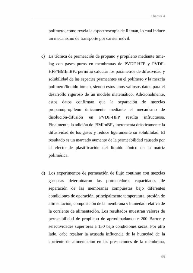
Chapter 4
99
polímero, como revela la espectroscopia de Raman, lo cual induce
un mecanismo de transporte por carrier móvil.
c) La técnica de permeación de propano y propileno mediante time-
lag con gases puros en membranas de PVDF-HFP y PVDF-
HFP/BMImBF4 permitió calcular los parámetros de difusividad y
solubilidad de las especies permeantes en el polímero y la mezcla
polímero/líquido iónico, siendo estos unos valiosos datos para el
desarrollo riguroso de un modelo matemático. Adicionalmente,
estos datos confirman que la separación de mezclas
propano/propileno únicamente mediante el mecanismo de
disolución-difusión en PVDF-HFP resulta infructuosa.
Finalmente, la adición de BMImBF4 incrementa drásticamente la
difusividad de los gases y reduce ligeramente su solubilidad. El
resultado es un marcado aumento de la permeabilidad causado por
el efecto de plastificación del líquido iónico en la matriz
polimérica.
d) Los experimentos de permeación de flujo continuo con mezclas
gaseosas determinaron las prometedoras capacidades de
separación de las membranas compuestas bajo diferentes
condiciones de operación, principalmente temperatura, presión de
alimentación, composición de la membrana y humedad relativa de
la corriente de alimentación. Los resultados muestran valores de
permeabilidad de propileno de aproximadamente 200 Barrer y
selectividades superiores a 150 bajo condiciones secas. Por otro
lado, cabe resaltar la acusada influencia de la humedad de la
corriente de alimentación en las prestaciones de la membrana,
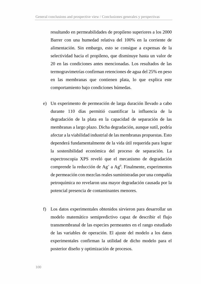
General conclusions and prospective view / Conclusiones generales y perspectivas
100
resultando en permeabilidades de propileno superiores a los 2000
Barrer con una humedad relativa del 100% en la corriente de
alimentación. Sin embargo, esto se consigue a expensas de la
selectividad hacia el propileno, que disminuye hasta un valor de
20 en las condiciones antes mencionadas. Los resultados de las
termogravimetrías confirman retenciones de agua del 25% en peso
en las membranas que contienen plata, lo que explica este
comportamiento bajo condiciones húmedas.
e) Un experimento de permeación de larga duración llevado a cabo
durante 110 días permitió cuantificar la influencia de la
degradación de la plata en la capacidad de separación de las
membranas a largo plazo. Dicha degradación, aunque sutil, podría
afectar a la viabilidad industrial de las membranas propuestas. Esto
dependerá fundamentalmente de la vida útil requerida para lograr
la sostenibilidad económica del proceso de separación. La
espectroscopia XPS reveló que el mecanismo de degradación
comprende la reducción de Ag+ a Ag0. Finalmente, experimentos
de permeación con mezclas reales suministradas por una compañía
petroquímica no revelaron una mayor degradación causada por la
potencial presencia de contaminantes menores.
f) Los datos experimentales obtenidos sirvieron para desarrollar un
modelo matemático semipredictivo capaz de describir el flujo
transmembranal de las especies permeantes en el rango estudiado
de las variables de operación. El ajuste del modelo a los datos
experimentales confirman la utilidad de dicho modelo para el
posterior diseño y optimización de procesos.
Chapter 4
101
g) La viabilidad del material de membrana propuesto para una
aplicación industrial se ha estudiado a través del diseño y la
optimización de procesos de separación mediante membranas.
Para ello, se ha analizado una aplicación parcial de esta tecnología
en forma de proceso híbrido membrana/destilación, así como una
sustitución completa de la destilación mediante procesos de
membrana multietapa. Los resultados revelan que el sistema
híbrido puede generar unos ahorros en los costes de operación
(OPEX) de entre el 33 y el 50% comparado con la destilación,
dependiendo del precio final de la membrana compuesta. Por otro
lado, una comparación del Valor Actual Neto de Costes (NPVC)
reveló que un proceso de membrana de dos etapas tiene un NPVC
del 25% del proceso de destilación, mientras que el proceso de dos
etapas y media no presenta ventajas salvo que la pureza de
propileno requerida exceda la pureza actualmente demandada por
la industria.
En conjunto, estos resultados confirman el notable potencial de las
membranas de PVDF-HFP/BMImBF4/AgBF4 implementadas en procesos
de separación alternativos para alcanzar la intensificación de procesos en
la separación industrial de mezclas propano/propileno. Sin embargo,
alcanzar una completa viabilidad a escalada industrial requiere resolver
retos adicionales. En primer lugar, los fenómenos de degradación del
carrier pueden acortar la vida útil de la membrana más allá de un estándar
competitivo. Por otro lado, la configuración de membrana juega un papel
clave a escala industrial, en donde altas densidades de empaquetado y

General conclusions and prospective view / Conclusiones generales y perspectivas
102
capas activas extremadamente delgadas son casi obligadas para asegurar la
sostenibilidad económica del proceso.
4.4. Recomendaciones para investigación futura
Basándose en las conclusiones generales extraídas de esta tesis, y
habiendo identificado los principales obstáculos en el camino hacia una
completa viabilidad a escala industrial, esta sección ofrece una breve guía
para futuros trabajos de investigación:
- Estudiar posibles estrategias para solucionar los problemas de
degradación del carrier. Este objetivo se puede lograr
desarrollando inhibidores de la degradación que pueden ser
añadidos como aditivos en la composición de la membrana. Otra
posibilidad comprende el desarrollo de métodos de regeneración
que reviertan el proceso de degradación desde Ag0 a Ag+.
- Sintetizar configuraciones de membrana atractivas desde un punto
de vista industrial, como son las fibras huecas. Esto se puede
conseguir mediante “coating” de fibras huecas porosas con el
material compuesto PVDF-HFP/BMImBF4/AgBF4, o
directamente mediante “spinning” de fibras huecas de doble capa.
En ambas estrategias el objetivo debe ser la formación de una capa
densa selectiva tan delgada como sea posible, en el rango de unos
pocos cientos de nanómetros.

Chapter 5 Scientific publications

Scientific publications
104
5.1. JCR Scientific publications
R. Zarca, A. Ortiz, D. Gorri, I. Ortiz, A practical approach to fixed-site-carrier facilitated transport modeling for the separation of propylene/propane mixtures through silver-containing polymeric membranes, Sep. Purif. Technol. 180 (2017) 82–89. (JCR Impact Factor (2017): 3.927, Q1). R. Zarca, A. Ortiz, D. Gorri, I. Ortiz, Generalized predictive modeling for facilitated transport membranes accounting for fixed and mobile carriers, J. Memb. Sci. 542 (2017) 168–176. (JCR Impact Factor (2017): 6.578, Q1). R. Zarca, A. Ortiz, D. Gorri, L.T. Biegler, I. Ortiz, Optimized distillation coupled with state-of-the-art membranes for propylene purification, J. Memb. Sci. 556 (2018) 321–328. (JCR Impact Factor (2017): 6.578, Q1).
A copy of the above-mentioned articles is presented hereunder.
Separation and Purification Technology 180 (2017) 82–89
Contents lists available at ScienceDirect
Separation and Purification Technology
journal homepage: www.elsevier .com/locate /seppur
A practical approach to fixed-site-carrier facilitated transport modelingfor the separation of propylene/propane mixtures through silver-containing polymeric membranes
http://dx.doi.org/10.1016/j.seppur.2017.02.0501383-5866/� 2017 Elsevier B.V. All rights reserved.
⇑ Corresponding author.E-mail address: [email protected] (I. Ortiz).
Raúl Zarca, Alfredo Ortiz, Daniel Gorri, Inmaculada Ortiz ⇑Department of Chemical and Biomolecular Engineering, University of Cantabria, Av. Los Castros 46, 39005 Santander, Spain
a r t i c l e i n f o
Article history:Received 9 January 2017Received in revised form 24 February 2017Accepted 25 February 2017Available online 27 February 2017
Keywords:PropylenePropaneAgBF4PVDF-HFPMembraneFixed-site carrier mathematical model
a b s t r a c t
In this work, a new consistent mathematical model for the description of the olefin flux through Ag+-containing polymeric dense membranes is proposed. A fixed site carrier ‘‘hopping” parameter acting asan effective permeability for this specific transport phenomenon is defined and calculated for the firsttime. This study reports a simple and versatile approach that can be incorporated into future modelsto simulate the more complex mobile/fixed hybrid mechanism acting in composite membranes.Furthermore, in order to validate the model, the proof of concept has been carried out with PVDF-HFP/
AgBF4 facilitated transport membranes. The experimental analysis has been performed by the continuousflow permeation method through flat membranes containing increasing silver loads, from 17 to 38% w/wat olefin partial pressures ranging from 0.5 to 1.5 bar and temperatures of 293 and 303 K. These mem-branes showed a promising performance, reaching values of propylene permeability up to 1800 Barrerand very high propylene/propane selectivities. The reported model constitutes a very useful tool for pro-cess optimisation and scale-up.
� 2017 Elsevier B.V. All rights reserved.
1. Introduction
The global production of ethylene and propylene exceeds 200million tones per year, being the purification stage responsiblefor 0.3% of the global energy use [1]. Current separation processes,mainly cryogenic distillation, consist on highly energy and capitalintensive operations [2], which typically account for 45–55% ofindustrial processes energy consumption [1]. Some alternative pro-cesses to cryogenic distillation have been proposed over the lasttimes, being the most studied: extractive distillation [3], physicaladsorption on molecular sieves [4], and chemical adsorption [5].Nonetheless, some problems as low olefin loads and complicatedregeneration cycles have prevent these alternatives from replacingtraditional distillation [6].
Recently, membrane technology has emerged as a possiblesolution that allows process intensification [7], which will lead toenergy and capital savings in many gas separation processes, suchas CO2 capture [8], CO separation [9], natural gas purification [10]and hydrogen production [11]. In the short term, membranes canbe used for bulk separation, using distillation for the final ‘‘refin-ing” of the product. Such hybrid systems would reduce the energy
requirements of olefin production by a factor of two or three [1]. Awide range of membrane compositions have been reported forolefin/paraffin separation, including liquid, polymeric and inor-ganic membranes [12–16]. However, these technologies face somemajor drawbacks. Liquid membranes show a serious lack of stabil-ity due to solvent evaporation [17]. Polymeric dense membranessuffer from poor performance in terms of selectivity and perme-ability due to the similar sizes of permeant species [18]. Lastly,inorganic membranes usually require complex and expensivepreparation methods and show low mechanical resistance.
The development of new materials has promoted recent studieson their application to gas separation. In this regard, new studiesassess the performance of nanocomposite membranes [19],mixed-matrix membranes containing metal organic frameworks(MOFs) [20–22], polymers with intrinsic microporosity (PIMs)[23] and membranes containing metallic nanoparticles [24],achieving high olefin/paraffin selectivities.
Among the membrane systems reported, those regarding thefacilitated transport of olefins using a transition metal cation ascarrier agent have shown great performance for olefin/paraffinseparations [25–27]. The main advantage of carrier mediated facil-itated transport membranes is their capability to achieve high val-ues of selectivity and permeability at the same time, thusovercoming the existing tradeoff between these two variables
Nomenclature
Am membrane effective area [m2]C concentration [mol L�1]
D diffusion coefficient [m2 s�1]
Ea activation energy [kJ mol�1]F molar flowrate [mol s�1]
J molar flux [mol m�2 s�1]
Keq equilibrium constant [m3 mol�1]KH fixed carrier effective permeability [mol bar�1 m�1 s�1]Kp heterogeneous equilibrium constant [bar�1]L membrane thickness [m3 mol�1 s�1]p pressure [bar]R universal gas constant [8.314 J mol�1 K�1]S gas solubility [mol bar�1 m�3]T temperature [K]x mole fraction [–]
Greek lettera fitting parameterb percolation threshold exponent [–]
Superscript/subscript0 feed sideC3H6 propyleneC3H8 propaneL permeate sideN2 nitrogenm membraneref reference
R. Zarca et al. / Separation and Purification Technology 180 (2017) 82–89 83
[28,29]. Facilitated transport membranes for olefin/paraffin sepa-ration are prepared dissolving a silver salt within a polymericmatrix, forming a solid membrane, usually known as polymer elec-trolyte. On this matter, Bai et al. [30] synthesized ethyl-cellulosemembranes modified with the incorporation of several metal-ions, achieving higher selectivity when testing silver cationsinstead of other transition metals. Kim et al. [31] tested EPR-coated polyester membranes with physically dispersed silveraggregates that dissolved in situ when in contact with the olefin,resulting in high selectivity towards the olefin; in addition, poly-merized ionic liquids have been also assessed as a matrix for theincorporation of silver cations with promising results [32]. Thesemembranes make use of the silver cations ability to selectivelyand reversibly coordinate with olefin molecules, following a p–bond complexation mechanism [33,34]. Additionally, our researchgroup has developed composite membranes incorporating ionicliquids to the matrix polymer in order to improve the separationperformance and stabilizing the silver cations in the membrane[28,35].
In this work, the use of dense polymeric facilitated transportmembranes made of PVDF-HFP fluoropolymer and AgBF4 silver saltis reported. When AgBF4 dissolves into the polymer, it dissociatesinto Ag+ and BF4- -ions. Then, Ag+ ions tend to bond with those poly-mer atoms that can donate electrons to stabilize silver cations. Pre-vious experimental studies have widely proven this distribution ofcations, assessing their interactions with electron donor atoms ofthe polymer by means of FTIR spectra [36,37]. Once the membraneis in contact with the olefin, p-bonding complexation between theolefin and the cation takes place. Finally, due to the partial pressuregradient, the olefin follows a hopping movement from one fixedcation to the next, giving place to fixed carrier transport mecha-nism [38,39]. PVDF-HFP fluoropolymer was selected because ofits well-known chemical, mechanical and thermal stability andits good miscibility with AgBF4 silver salt; furthermore, besidesthe copolymerization with HFP decreases its crystallinity degreeto around 0.3 [40], certain crystallinity in the polymer structuremay reduce the paraffin sorption, while the olefin solubilityremains high due to its complexation with the silver cations,increasing the selectivity of the membrane.
Previously, interesting works have been reported trying todescribe this facilitated transport phenomenon in similar systems.In this regard, Smith and Quinn [41] studied the facilitated trans-port of carbon monoxide through cuprous chloride solutions;Ravanchi et al. [42] and Kasahara et al. [43] developed mathemat-ical models for propane/propylene separation using supported
liquid membranes and ion-gel membranes composed of gelledionic liquids on PTFE supports, respectively.
The present work proposes a novel mathematical descriptionfor propylene flux through solid PVDF-HFP/Ag+ facilitated trans-port membranes. Although previous reports of this research grouphave assessed the addition of ionic liquids as additives to promotecarrier mobility [28], its use has been avoided in this study in orderto limit the transport mechanisms to fixed site carrier andsolution-diffusion. The mathematical approach at this stageinvolves the experimental determination of the activation energy(Ea), the equilibrium constant (Kp) and the influence of silver con-centration (b), whereas the fitting parameter (a) has been esti-mated using Aspen Custom Modeler software. The model is ableto describe the influence of the main operating variables on propy-lene flux, such as temperature, partial pressure and membranecomposition. This model is the necessary tool for future processdesign, scale-up and optimization.
2. Experimental
2.1. Chemicals
Propylene and propane gases were purchased from Praxair witha purity of 99.5% for both gases. Poly(vinylidene fluoride-co-hexafluoropropylene) (PVDF-HFP) was supplied by Sigma Aldrich. Silvertetrafluoroborate (AgBF4) with a minimum purity of 99% was pur-chased from Apollo Scientific Ltd. Tetrahydrofuran (THF) was usedas solvent for membrane synthesis. All chemicals were used asreceived with no further purification.
2.2. Membrane synthesis
PVDF-HFP/AgBF4 membranes were synthesized using the sol-vent casting method. The selected amount of PVDF-HFP is dis-solved in 10 mL of THF by stirring in a sealed glass vial toprevent solvent evaporation. After 24 h of stirring at room temper-ature, the vial is heated at 50 �C during 5 min until the polymer iscompletely dissolved. Once the polymeric solution is prepared, it ismixed with the desired amount of silver salt and stirred for 10 min.Finally, the membrane precursor is poured in a Petri dish andlocated in a vacuum oven for 24 h at 25 �C and 300 mbar underdark conditions. The resulting thickness of the prepared densefilms depends on the silver load, but in all cases, it isaround 60 ± 10 lm. For calculation purposes, the real thickness of
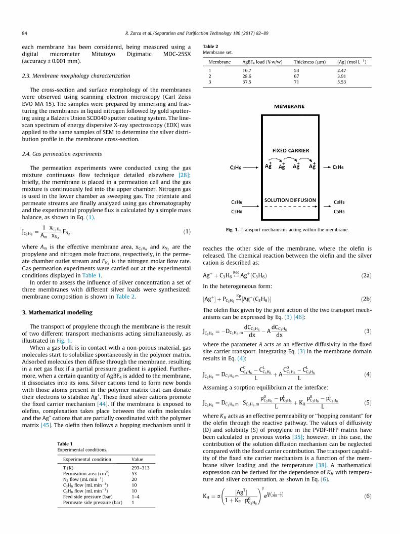
Table 2Membrane set.
Membrane AgBF4 load (% w/w) Thickness (lm) [Ag] (mol L�1)
1 16.7 53 2.472 28.6 67 3.913 37.5 71 5.53
Fig. 1. Transport mechanisms acting within the membrane.
84 R. Zarca et al. / Separation and Purification Technology 180 (2017) 82–89
each membrane has been considered, being measured using adigital micrometer Mitutoyo Digimatic MDC-25SX(accuracy ± 0.001 mm).
2.3. Membrane morphology characterization
The cross-section and surface morphology of the membraneswere observed using scanning electron microscopy (Carl ZeissEVO MA 15). The samples were prepared by immersing and frac-turing the membranes in liquid nitrogen followed by gold sputter-ing using a Balzers Union SCD040 sputter coating system. The line-scan spectrum of energy dispersive X-ray spectroscopy (EDX) wasapplied to the same samples of SEM to determine the silver distri-bution profile in the membrane cross-section.
2.4. Gas permeation experiments
The permeation experiments were conducted using the gasmixture continuous flow technique detailed elsewhere [28];briefly, the membrane is placed in a permeation cell and the gasmixture is continuously fed into the upper chamber. Nitrogen gasis used in the lower chamber as sweeping gas. The retentate andpermeate streams are finally analyzed using gas chromatographyand the experimental propylene flux is calculated by a simple massbalance, as shown in Eq. (1).
JC3H6¼ 1
Am
xC3H6
xN2
FN2 ð1Þ
where Am is the effective membrane area, xC3H6 and xN2 are thepropylene and nitrogen mole fractions, respectively, in the perme-ate chamber outlet stream and FN2 is the nitrogen molar flow rate.Gas permeation experiments were carried out at the experimentalconditions displayed in Table 1.
In order to assess the influence of silver concentration a set ofthree membranes with different silver loads were synthesized;membrane composition is shown in Table 2.
3. Mathematical modeling
The transport of propylene through the membrane is the resultof two different transport mechanisms acting simultaneously, asillustrated in Fig. 1.
When a gas bulk is in contact with a non-porous material, gasmolecules start to solubilize spontaneously in the polymer matrix.Adsorbed molecules then diffuse through the membrane, resultingin a net gas flux if a partial pressure gradient is applied. Further-more, when a certain quantity of AgBF4 is added to the membrane,it dissociates into its ions. Silver cations tend to form new bondswith those atoms present in the polymer matrix that can donatetheir electrons to stabilize Ag+. These fixed silver cations promotethe fixed carrier mechanism [44]. If the membrane is exposed toolefins, complexation takes place between the olefin moleculesand the Ag+ cations that are partially coordinated with the polymermatrix [45]. The olefin then follows a hopping mechanism until it
Table 1Experimental conditions.
Experimental condition Value
T (K) 293–313Permeation area (cm2) 53N2 flow (mL min�1) 20C3H6 flow (mL min�1) 10C3H8 flow (mL min�1) 10Feed side pressure (bar) 1–4Permeate side pressure (bar) 1
reaches the other side of the membrane, where the olefin isreleased. The chemical reaction between the olefin and the silvercation is described as:
Agþ þ C3H6 $Keq AgþðC3H6Þ ð2aÞIn the heterogeneous form:
½Agþ� þ PC3H6 $Kp ½AgþðC3H6Þ� ð2bÞ
The olefin flux given by the joint action of the two transport mech-anisms can be expressed by Eq. (3) [46]:
JC3H6¼ �DC3H6 ;m
dCC3H6
dx� A
dCC3H6
dxð3Þ
where the parameter A acts as an effective diffusivity in the fixedsite carrier transport. Integrating Eq. (3) in the membrane domainresults in Eq. (4):
JC3H6¼ DC3H6 ;m
C0C3H6
� CLC3H6
Lþ A
C0C3H6
� CLC3H6
Lð4Þ
Assuming a sorption equilibrium at the interface:
JC3H6¼ DC3H6 ;m � SC3H6 ;m
p0C3H6
� pLC3H6
Lþ KH
p0C3H6
� pLC3H6
Lð5Þ
where KH acts as an effective permeability or ‘‘hopping constant” forthe olefin through the reactive pathway. The values of diffusivity(D) and solubility (S) of propylene in the PVDF-HFP matrix havebeen calculated in previous works [35]; however, in this case, thecontribution of the solution diffusion mechanism can be neglectedcompared with the fixed carrier contribution. The transport capabil-ity of the fixed site carrier mechanism is a function of the mem-brane silver loading and the temperature [38]. A mathematicalexpression can be derived for the dependence of KH with tempera-ture and silver concentration, as shown in Eq. (6).
KH ¼ a½AgT�
1þ KP � p0C3H6
!b
eEaR
1293�1
Tð Þ ð6Þ

R. Zarca et al. / Separation and Purification Technology 180 (2017) 82–89 85
The effect of temperature is given by an Arrhenius type expression,while the term in brackets is the concentration of uncomplexed sil-ver cations, as obtained from the chemical equilibrium. The expo-nent b was introduced to correct the silver concentrationinfluence on the propylene flux, given the percolation thresholdobserved in these membranes by several authors [47–49]. Theparameter a is the fitting parameter of the model.
On the other hand, given that propane is only affected by fickiandiffusion, its flux can be easily described by the solution-diffusionequation:
JC3H8¼ DC3H8 ;m � SC3H8 ;m
p0C3H8
� pLC3H8
Lð7Þ
4. Results and discussion
4.1. Membrane morphology
Fig. 2 displays the SEM photographs of a PVDF-HFP membraneand PVDF-HFP/AgBF4 membranes 1 and 3. In all cases the
Fig. 2. Cross-section and surface morphology of: (A) Pure PVDF-HFP mem
Fig. 3. SEM-EDX scan-line and silver distribution profile
PVDF-HFP forms a homogeneous dense polymeric matrix with nosigns of porosity or differentiated layers. Furthermore, no particleclusters appear in the polymer electrolyte membranes, indicatingthat the added salt is completely dissolved.
The EDX spectra of the membrane with the highest silver load-ing displayed in Fig. 3 shows a uniform distribution of the elementsilver along the cross-section of the membrane, with no evidenceof silver particles formation. This is in good agreement with thepreviously discussed works on the interactions between the Ag+
cations and the polymer matrix [36,37].
4.2. Permeation results
In this section, the permeation results are discussed; the exper-imental propylene flux through the membranes 1–3 as a functionof propylene partial pressure is depicted in Fig. 4 at 293 and303 K, respectively.
As the difference of propylene partial pressure is the drivingforce in the permeation process, the olefin flux increases when
brane, (B) membrane 1 [Ag] = 2.47 M, (C) membrane 3 [Ag] = 5.53 M.
in the cross-section of membrane 3 [Ag] = 5.53 M.

0
50
100
150
200
250
300
350
400
0 0.5 1 1.5 2
J C3H
6(x
106
mol
·m-2
·s-1
)
P C3H6 (bar)
A
Membrane 3
Membrane 2
Membrane 1
0
100
200
300
400
500
600
700
0 0.5 1 1.5 2
J C3H
6(x
106
mol
·m-2
·s-1
)
P C3H6 (bar)
B
Membrane 3
Membrane 2
Membrane 1
Fig. 4. Propylene flux at (a) 293 and (b) 303 K as a function of the feed partialpressure in membrane 1 [Ag] = 2.47 M, membrane 2 [Ag] = 3.91 M and membrane 3[Ag] = 5.53 M.
1
10
100
1000
0 0.5 1 1.5 2
J C3H
X(x
106
mol
·m-2
·s-1
)
P C3HX (bar)
Propylene 293 K
Propylene 303 K
Propane 293 K
Propane 303 K
Fig. 5. Experimental fluxes of propylene and propane in membrane 3 at 293 and303 K, at different partial pressure.
86 R. Zarca et al. / Separation and Purification Technology 180 (2017) 82–89
its feed partial pressure rises. In contrast to the conventionalsolution-diffusion transport mechanism, that describes a linearincrease of the permeate flux with increasing driving force, i.e. par-tial pressure difference, these membranes display the characteris-tic fixed-site-carrier facilitated transport profile describedelsewhere [50]. At very low values of the driving force, most partof the transported molecules follow the complexing mechanism,resulting in a non-linear profile. On the other hand, for high drivingforces, every silver cation is bound to propylene molecules and thecarrier becomes saturated. In this state, any flux increase is mainlyinduced by the solution-diffusion mechanism, and thus, the lineartrend is only achieved after surpassing a threshold value of the par-tial pressure gradient.
Comparing Fig. 4(a) and (b) it can be observed that the temper-ature has a strong influence on the permeation process, increasingthe flux of propylene. This increase of the olefin flux is due to theenhancement in the gas diffusivity, as reported before [35]. Thetemperature also has a positive influence on the rate of complexa-tion and decomplexation reactions, thus enhancing the olefin facil-itated transport. In contrast to diffusivity, the solubility of bothgases slightly decreases with temperature; nonetheless, the influ-ence of this trend is completely overlapped by the diffusivity effect.However, as the paraffin diffusivity undergoes an increasing trendwith temperature, it results in a selectivity decrease towards theolefin at higher temperatures.
Pristine PVDF-HFP copolymer is known for being a low perme-able material. This property combined with transport facilitationtowards propylene yields very high selectivity. In fact, the propaneconcentration in the permeate stream when testing membranes 1and 2 was below the gas chromatograph detection limit (0.025 vol.
%). The permeate stream of membrane 3 contained a minor quan-tity of propane at the higher feed pressures, as displayed in Fig. 5.The resulting selectivity ranges from 100 to 300. Given that previ-ous studies involving pure gases report lower values of propanepermeability in PVDF-HFP [35], a dragging effect caused by thehigh propylene fluxes is probably happening in membrane 3,resulting in a propane permeability increase. Fig. 5 shows the dif-ference between the experimental fluxes of propylene andpropane.
Thus, these experimental results demonstrate that it is possibleto achieve high propylene flux and selectivity even at low partialpressures and moderate temperatures.
Comparing all three membranes in terms of silver loadingand propylene flux, one can observe that the silver concentra-tion has a major influence on the olefin permeability. Whenthe silver content increases within the membrane, more silvercations are available to coordinate with olefin molecules. Theresult is a noticeable increase in propylene facilitated transportthat follows an exponential trend, Fig. 6. A similar behaviourwas reported by Yoon et al. [47] in PEOx and PVP with AgBF4and AgCF3SO3 silver salts, by Morisato et al. [48] in PA-12-PTMO/AgBF4 membranes, and by Kim et al. [49] in differentpolymer/silver membranes, although it has not been previouslyreported in PVDF-HFP fluoropolymer. This trend evidences apercolation threshold; at low carrier concentrations, the facili-tated transport is almost negligible, while increasing the con-centration results in a major increase of the olefin flux. Thisphenomenon is related to the proximity between active sites;at low concentrations, the distance between two consecutivecations is too large to allow the facilitated transport; on theother hand, at higher concentrations the silver cations are closeenough to transport the olefin. In these membranes, the perco-lation threshold seems to be surpassed at silver concentrationshigher than 2.5 mol�L�1.
4.3. Mathematical model
One of the main targets of this work is to provide a simple yeteffective model to predict the olefin flux in this polymer/silver sys-tem. This tool will be useful to design and optimize commercialattractive configurations as spiral wound or hollow fiber geome-tries. The model contains one fitting parameter and three calcu-lated parameters.
In order to avoid interferences in parametric sensitivity, theexperimental determination of the activation energy, the equilib-rium constant and the exponent b has been carried out isolating

0
100
200
300
400
500
600
700
800
0 0.5 1 1.5 2
J C3H
6 (x1
06 mol
·m-2
·s-1
)
P C3H6 (bar)
Membrane 3 T=293K
Membrane 2 T=293K
Membrane 1 T=293K
Membrane 3 T=303K
Membrane 2 T=303K
Membrane 1 T=303K
Model
Fig. 7. Propylene experimental flux and model prediction for the membranes 1 to 3at 293 and 303 K, and at different feed partial pressures.
400
500
600
700
800
x (x
106 m
ol·m
-2·s
-1)
10
110
210
310
410
510
610
710
0 2 4 6
C 3H6
Perm
eabi
lity
(Bar
rer)
[Ag] (mol·L-1)
A
0.5 bar
0.75 bar
1 bar
1.5 bar
0
200
400
600
800
1000
1200
1400
1600
1800
2000
0 1 2 3 4 5 6
Perm
eabi
lity
C 3H6 (
Barr
er)
[Ag] (mol·L-1)
B
0.5 bar
0.75 bar
1 bar
1.5 bar
Fig. 6. Permeability of propylene with increasing silver concentration at (a) 293and (b) 303 K.
R. Zarca et al. / Separation and Purification Technology 180 (2017) 82–89 87
the influence of temperature from the influence of silverconcentration. The values of calculated parameters are shown inTable 3.
To calculate the activation energy of the permeation process,experimental data at constant pressure and constant silver concen-tration, modifying the temperature, were fitted to an Arrheniustype equation, Eq. (8):
lnKH ¼ lna0 þ EaR
1Tref
� 1T
� �ð8Þ
Using the same methodology, the equilibrium constant KP and theexponent b were determined by regression of permeability data atconstant temperature, with silver concentration and olefin partialpressure, Eq. (9):
KH ¼ a00 Ag1þ KP � pi
� �b
ð9Þ
Aspen Custom Modeler software was used to fit the experimen-tal data to the model equations and estimate the fitting param-eter a, which has a value of 3.24 � 10�11 for this particular casestudy.
Table 3Calculated model parameters.
Parameter Value
Activation energy, Ea (kJ mol�1) 61Equilibrium constant, Kp (bar�1) 0.12Beta exponent, b 4.235
Once the model parameters are determined, the modeldescribes the permeation process of propylene through the facili-tated transport membrane, providing that all operating variablesare inside the studied range. Fig. 7 shows experimental and modelflux values of propylene at several temperatures and olefin partialpressures with membranes 1 to 3.
The estimated propylene fluxes are represented against theexperimental propylene fluxes in the parity graph shown inFig. 8. In the parity graph, a 15% error range is also displayed, prov-ing that the majority of points fall within this range, and checkingthe adequacy of the proposed model to describe the experimentalbehavior of propane/propylene separation using PVDF-HFP/Ag+
membranes.
4.4. Membranes comparison
Various polymer electrolytes comprising different polymermatrices and silver salts have been previously reported for propy-lene/propane separation. Table 4 displays the selectivity valuesachieved by other authors when similar propylene/propane gasmixtures were tested. It is remarkable the performance of thePDMS/AgBF4 membranes reported by Kim et al. [51]; with the par-ticularity that the silver cations are not bounded to the polymerchains, according to the authors; silver remains forming ionicaggregates that progressively dissolve upon its contact with theolefin. The use of PVDF-HFP as polymeric matrix reported in thiswork yields higher selectivity compared with other membranesthat use the same silver salt, and shows great potential for theintensification of the olefin/paraffin separation process.
0
100
200
300
0 100 200 300 400 500 600 700
Pred
icte
d C 3H
6 flu
Experimental C3H6 flux (x106 mol·m-2·s-1)
Fig. 8. Model parity graph with a 15% error range.

Table 4Comparison with previous reported facilitated transport membranes.
Membrane C3H6/C3H8 gas mixture Feed pressure (bar) Thickness (lm) Permeance (GPU) a Selectivity Ref.
Poly(ethylene-co-propylene)/62 wt.% AgBF4 50/50 1–2 7 55 [31]PEBAX 1657/50 wt.% AgBF4 50/50 4 25 4b 17.2 [27]PEBAX 1657/50 wt.% AgBF4 66/34 2 25 5b 20.2 [27]PEOx/AgBF4 [Ag]/[C = O] 1:1 50/50 2.76 1 35 58 [47]PEOx/AgCF3SO3 [Ag]/[C = O] 1:1 50/50 2.76 1 32 19 [47]PVP/AgBF4 [Ag]/[C = O] 1:1 50/50 2.76 1 36 65 [47]PVP/AgCF3SO3 [Ag]/[C = O] 1:1 50/50 2.76 1 28 18 [47]PDMS/57 wt.% AgBF4 50/50 2 13 150 [51]PVDF-HFP/37.5 wt.% AgBF4 50/50 2 71 25b 300 This work
a Permeance in GPU. 1 GPU = 1 � 10�6 cm3 (STP)/cm2 s cmHg.b Calculated from reported permeability and thickness.
88 R. Zarca et al. / Separation and Purification Technology 180 (2017) 82–89
5. Conclusions
A mathematical expression for the ‘‘effective permeability” ofpropylene by the fixed carrier mechanism has been deduced andthe fitting parameter has been estimated based on experimentaldata. The validity of the model has been checked by comparingsimulated and experimental permeation data for propylene/pro-pane gas mixtures in PVDF-HFP/Ag+.
The resulting olefin fluxes follow the characteristic trend offacilitated transport processes when increasing the feed pressure,and indicate a promising performance in terms of propylene per-meability. The silver loading dramatically increases the propyleneflux in an exponential trend, which suggests the existence of a con-centration threshold. The comparison between experimental andpredicted values and the model parity graph suggest a reliablegoodness of fit.
The mathematical approach reported in this work is susceptibleto be applied in those membrane systems where the fixed carriermechanism is present and allows to calculate its contribution tothe total permeate flux in a fast and simple manner. Therefore, thismodel will be a valuable tool for future design and optimization ofmore complex propylene/propane separation systems (i.e. mobile-fixed carrier hybrid membranes) in more efficient processconfigurations.
Acknowledgement
Financial support from the Spanish Ministry of Science underthe projects CTQ2015-66078-R and CTQ2016-75158-R (MINECO,Spain-FEDER 2014–2020) is gratefully acknowledged. Raúl Zarcaalso thanks the Universidad de Cantabria for a postgraduatefellowship.
References
[1] D.S. Sholl, R.P. Lively, Seven chemical separations to change the world, Nature532 (2016) 435–437.
[2] J.L. Humphrey, A.F. Seibert, R.A. Koort, Separation Technologies: Advances andPriorities, U.S. Department of Energy Report No. DOE/ID/12920-1, 1991.
[3] R. Kumar, J.M. Prausnitz, C.J. King, Process design considerations for extractivedistillation: separation of propylene-propane, in: D. Tassios (Ed.), Extractiveand Azeotropic Distillation, American Chemical Society, Washington D.C.,1974, pp. 16–34.
[4] C.M. Shu, S. Kulvaranon, M.E. Findley, A.I. Liapis, Experimental andcomputational studies on propane-propylene separation by adsorption andvariable-temperature stepwise desorption, Sep. Technol. 1 (1990) 18–28.
[5] R.T. Yang, Adsorbents: Fundamentals and Applications, John Wiley & Sons,Hoboken, NJ, 2003, pp. 191–230.
[6] R.B. Eldridge, Olefin/paraffin separation technology: a review, Ind. Eng. Chem.Res. 32 (1993) 2208–2212.
[7] J. Charpentier, In the frame of globalization and sustainability, processintensification, a path to the future of chemical and process engineering(molecules into money), Chem. Eng. J. 134 (2007) 84–92.
[8] T.C. Merkel, X. Wei, Z. He, L.S. White, J.G. Wijmans, R.W. Baker, Selectiveexhaust gas recycle with membranes for CO2 capture from natural gascombined cycle power plants, Ind. Eng. Chem. Res. 52 (2013) 1150–1159.
[9] G. Zarca, W.J. Horne, I. Ortiz, A. Urtiaga, J.E. Bara, Synthesis and gas separationproperties of poly(ionic liquid)-ionic liquid composite membranes containinga copper salt, J. Membr. Sci. 515 (2016) 109–114.
[10] M. Askari, T. Chung, Natural gas purification and olefin/paraffin separationusing thermal cross-linkable co-polyimide/ZIF-8 mixed matrix membranes, J.Membr. Sci. 444 (2013) 173–183.
[11] R. Swaidan, B. Ghanem, I. Pinnau, Fine-tuned intrinsicallyultramicroporous polymers redefine the permeability/selectivity upperbounds of membrane-based air and hydrogen separations, ACS MacroLett. 4 (2015) 947–951.
[12] J. Caro, M. Noack, P. Kölsch, R. Schäfer, Zeolite membranes - state of theirdevelopment and perspective, Microporous Mesoporous Mater. 38 (2000) 3–24.
[13] Y.S. Lin, I. Kumakiri, B.N. Nair, H. Alsyouri, Microporous inorganic membranes,Sep. Purif. Methods 31 (2002) 229–379.
[14] M. Fallanza, A. Ortiz, D. Gorri, I. Ortiz, Experimental study of the separation ofpropane/propylene mixtures by supported ionic liquid membranes containingAg+–RTILs as carrier, Sep. Purif. Technol. 97 (2012) 83–89.
[15] S. Najari, S.S. Hosseini, M. Omidkhah, N.R. Tan, Phenomenological modelingand analysis of gas transport in polyimide membranes for propylene/propaneseparation, RSC Adv. 5 (2015) 47199–47215.
[16] K.-S. Liao, J.-Y. Lai, T.-S. Chung, Metal ion modified PIM-1 and its applicationfor propylene/propane separation, J. Membr. Sci. 515 (2016) 36–44.
[17] M. Teramoto, H. Matsuyama, T. Yamashiro, Y. Katayama, Separation ofethylene from ethane by supported liquid membranes containing silver-nitrate as a carrier, J. Chem. Eng. Japan 19 (1986) 419–424.
[18] R. Faiz, K. Li, Polymeric membranes for light olefin/paraffin separation,Desalination 287 (2012) 82–97.
[19] H. Sun, B. Yuan, P. Li, T. Wang, Y. Xu, Preparation of nanoporous graphene andthe application of its nanocomposite membrane in propylene/propaneseparation, Funct. Mater. Lett. 08 (2015) 1550019.
[20] U. Böhme, B. Barth, C. Paula, A. Kuhnt, W. Schwieger, A. Mundstock, J. Caro, M.Hartmann, Ethene/ethane and propene/propane separation via the olefin andparaffin selective metal-organic framework adsorbents CPO-27 and ZIF-8,Langmuir 29 (2013) 8592–8600.
[21] G. Chang, M. Huang, Y. Su, H. Xing, B. Su, Z. Zhang, Q. Yang, Y. Yang, et al.,Immobilization of Ag(I) into a metal-organic framework with -SO3H sites forhighly selective olefin-paraffin separation at room temperature, Chem.Commun. 51 (2015) 2859–2862.
[22] H.T. Kwon, H. Jeong, Improving propylene/propane separation performance ofZeolitic-Imidazolate framework ZIF-8 Membranes, Chem. Eng. Sci. 124 (2015)20–26.
[23] R.J. Swaidan, X. Ma, E. Litwiller, I. Pinnau, Enhanced propylene/propaneseparation by thermal annealing of an intrinsically microporous hydroxyl-functionalized polyimide membrane, J. Membr. Sci. 495 (2015) 235–241.
[24] C.G.F. Rezende, C.P. Borges, A.C. Habert, Sorption of propylene and propane inpolyurethane membranes containing silver nanoparticles, J. Appl. Polym. Sci.133 (2016).
[25] J.H. Kim, B.R. Min, J. Won, S.H. Joo, H.S. Kim, Y.S. Kang, Role of polymer matrixin polymer/silver complexes for structure, interactions, and facilitated olefintransport, Macromolecules 36 (2003) 6183–6188.
[26] J.H. Kim, B.R. Min, J. Won, Y.S. Kang, Revelation of facilitated olefin transportthrough silver-polymer complex membranes using anion complexation,Macromolecules 36 (2003) 4577–4581.
[27] R. Surya Murali, K. Yamuna Rani, T. Sankarshana, A.F. Ismail, S. Sridhar,Separation of binary mixtures of propylene and propane by facilitatedtransport through silver incorporated poly(ether-block-amide) membranes,Oil Gas Sci. Technol. 70 (2015) 381–390.
[28] M. Fallanza, A. Ortiz, D. Gorri, I. Ortiz, Polymer-ionic liquid compositemembranes for propane/propylene separation by facilitated transport, J.Membr. Sci. 444 (2013) 164–172.
[29] L. Liu, X. Feng, A. Chakma, Unusual behavior of poly(ethylene oxide)/AgBF4polymer electrolyte membranes for olefin–paraffin separation, Sep. Purif.Technol. 38 (2004) 255–263.
[30] S. Bai, S. Sridhar, A.A. Khan, Recovery of propylene from refinery off-gas usingmetal incorporated ethylcellulose membranes, J. Membr. Sci. 174 (2000)67–79.

R. Zarca et al. / Separation and Purification Technology 180 (2017) 82–89 89
[31] J.H. Kim, B.R. Min, Y.W. Kim, S.W. Kang, J. Won, Y.S. Kang, Novel compositemembranes comprising silver salts physically dispersed in poly(ethylene-co-propylene) for the separation of propylene/propane, Macromol. Res. 15 (2007)343–347.
[32] L.C. Tomé, D. Mecerreyes, C.S.R. Freire, L.P.N. Rebelo, I.M. Marrucho, Polymericionic liquid membranes containing IL-Ag+ for ethylene/ethane separation viaolefin-facilitated transport, J. Mater. Chem. A 2 (2014) 5631–5639.
[33] J.S. Dewar, A review of the pi-complex theory, Bull. Soc. Chim. Fr. 18 (1951)C71–C79.
[34] L.M. Galán Sánchez, G.W. Meindersma, A.B. Haan, Potential of silver-basedroom-temperature ionic liquids for ethylene/ethane separation, Ind. Eng.Chem. Res. 48 (2009) 10650–10656.
[35] R. Zarca, A. Ortiz, D. Gorri, I. Ortiz, Facilitated transport of propylene throughcomposite polymer-ionic liquid membranes. Mass transfer analysis, Chem.Prod. Process Model. 11 (2016) 77–81, http://dx.doi.org/10.1515/cppm-2015-0072.
[36] J. Chang, S.W. Kang, CO2 separation through poly(vinylidene fluoride-co-hexafluoropropylene) membrane by selective ion channel formed bytetrafluoroboric acid, Chem. Eng. J. 306 (2016) 1189–1192.
[37] S. Sunderrajan, B.D. Freeman, C.K. Hall, I. Pinnau, Propane and propylenesorption in solid polymer electrolytes based on poly(ethylene oxide) and silversalts, J. Membr. Sci. 182 (2001) 1–12.
[38] E.L. Cussler, R. Aris, A. Bhown, On the limits of facilitated diffusion, J. Membr.Sci. 43 (1989) 149–164.
[39] R.D. Noble, Analysis of facilitated transport with fixed site carrier membranes,J. Membr. Sci. 50 (1990) 207–214.
[40] S. Abbrent, J. Plestil, D. Hlavata, J. Lindgren, J. Tegenfeldt, Å. Wendsjö,Crystallinity and morphology of PVdF-HFP-based gel electrolytes, Polymer42 (2001) 1407–1416.
[41] D.R. Smith, J.A. Quinn, The facilitated transport of carbon monoxide throughcuprous chloride solutions, AIChE J. 26 (1980) 112–120.
[42] M.T. Ravanchi, T. Kaghazchi, A. Kargari, Facilitated transport separation ofpropylene-propane: experimental and modeling study, Chem. Eng. Process. 49(2010) 235–244.
[43] S. Kasahara, E. Kamio, R. Minami, H. Matsuyama, A facilitated transport ion-gelmembrane for propylene/propane separation using silver ion as a carrier, J.Membr. Sci. 431 (2013) 121–130.
[44] R. Faiz, K. Li, Olefin/paraffin separation using membrane based facilitatedtransport/chemical absorption techniques, Chem. Eng. Sci. 73 (2012) 261–284.
[45] A. Ortiz, L.M. Galán Sanchez, D. Gorri, A.B. De Haan, I. Ortiz, Reactive ionicliquid media for the separation of propylene/propane gaseous mixtures, Ind.Eng. Chem. Res. 49 (2010) 7227–7233.
[46] R.D. Noble, Generalized microscopic mechanism of facilitated transport infixed site carrier membranes, J. Membr. Sci. 75 (1992) 121–129.
[47] Y. Yoon, J. Won, Y.S. Kang, Polymer electrolyte membranes containing silverion for facilitated olefin transport, Macromolecules 33 (2000) 3185–3186.
[48] A. Morisato, Z. He, I. Pinnau, T.C. Merkel, Transport properties of PA12-PTMO/AgBF4 solid polymer electrolyte membranes for olefin/paraffin separation,Desalination 145 (2002) 347–351.
[49] J.H. Kim, S.W. Kang, Y.S. Kang, Threshold silver concentration for facilitatedolefin transport in polymer/silver salt membranes, J. Polym. Res. 19 (2012)9753.
[50] R.D. Noble, C.A. Koval, Review of facilitated transport membranes, in: Y.Yampol’skii, I. Pinnau, B. Freeman (Eds.), Materials Science of Membranes forGas and Vapor Separation, John Wiley & Sons, Hoboken, NJ, 2006, pp. 411–435.
[51] J.H. Kim, J. Won, Y.S. Kang, Olefin-induced dissolution of silver salts physicallydispersed in inert polymers and their application to olefin/paraffin separation,J. Membr. Sci. 241 (2004) 403–407.

Contents lists available at ScienceDirect
Journal of Membrane Science
journal homepage: www.elsevier.com/locate/memsci
Generalized predictive modeling for facilitated transport membranesaccounting for fixed and mobile carriers
Raúl Zarca, Alfredo Ortiz, Daniel Gorri, Inmaculada Ortiz⁎
Department of Chemical and Biomolecular Engineering, University of Cantabria, Av. Los Castros 46, 39005 Santander, Spain
A R T I C L E I N F O
Keywords:Propylene-propane separationFacilitated transportSilverMembraneMathematical model
A B S T R A C T
The present work expands previous modeling knowledge on facilitated transport membranes for olefin/paraffinseparation. A new robust and practical mathematical model for the description of light olefin flux in compositepolymer/ionic liquid/Ag+ membranes is reported. The model takes into account three different transport me-chanisms, i.e., solution-diffusion, fixed-site carrier and mobile carrier transport mechanisms. Fixed-site carriercontribution that appears thanks to the bounding of silver cations with the polymer chains is described through a“hopping parameter”. Furthermore, given that the addition of an ionic liquid to the membrane compositionpromotes carrier mobility, the inclusion of a dedicated expression is necessary for a realistic description ofmobile-carrier transport phenomena. The contribution of each mechanism in weighted based on the membranecomposition.
In order to check the model suitability, simulated values have been matched to experimental data obtained bycontinuous flow propane/propylene permeation experiments through PVDF-HFP/BMImBF4/AgBF4 compositemembranes, working with 50:50 gas mixtures at different temperature and pressure. The resultant model offersgood predictions for olefin flux and provides a very useful tool for process optimization and scaling-up. To ourknowledge, this is the first time that mobile and fixed site carrier mechanisms performance are simultaneouslymodeled considering the influence of temperature, pressure and carrier loading.
1. Introduction
The separation of light olefin/paraffin mixtures has been recentlydefined as one of the key chemical separations that can bring greatglobal benefits once improved. Replacing traditional distillation by newprocesses that do not require a phase change could lower the energyintensity of the process by a factor of ten [1]. In this sense, membranetechnology offers a modular and cost-effective solution able to reducethe energy demand of the separation process by means of process in-tensification [2].
Several approaches have been reported to synthesize effectiveolefin/paraffin separation membranes. The simplest way is to exploitthe intrinsic separation properties of polymers in a dense membraneconfiguration. Dense polymeric membranes made of glassy, rubberyand cellulosic polymers perform high selectivities at the expense of lowpermeabilities [3–6]. More recently, new materials have been tested fortheir application in alkane/alkene separation, including polymers withintrinsic microscopy [7,8], metal-organic frameworks [9,10], carbonmolecular sieves [11,12] and graphene [13], displaying a wide dis-tribution of results.
However, the intrinsic separation properties of polymers are vastlyimproved when a metallic cation with the ability to reversibly and se-lectively react with the olefin is dissolved in the polymer matrix, re-sulting in the facilitated transport mechanism [14]. In this context,silver cations are known for their capability to form stable complexeswith the olefin via π-bonding mechanism [15,16].
Gas separation based on facilitated transport has been approachedworking in liquid phase, mainly in the form of supported liquid mem-branes [17–20], but their poor mechanical stability and the solventlosses by evaporation are major drawbacks for real industrial applica-tion, especially when subjected to pressure gradients [21]. In order toovercome this handicap, the use of ionic liquids as liquid phase hasbeen recently assessed [22]. Besides their negligible vapor pressure,ionic liquids are non-flammable excellent solvents whose chemical andphysical properties can be tailored by a judicious selection of cation,anion, and substituents [23,24].
The unique properties of ionic liquids can be used to improvemembrane performance in polymer electrolyte membranes. On the onehand, the presence of an ionic liquid within the free volume of thepolymer promotes mobility among the silver cations which, after
http://dx.doi.org/10.1016/j.memsci.2017.08.010Received 21 June 2017; Received in revised form 27 July 2017; Accepted 4 August 2017
⁎ Corresponding author.E-mail address: [email protected] (I. Ortiz).
Journal of Membrane Science 542 (2017) 168–176
Available online 09 August 20170376-7388/ © 2017 Elsevier B.V. All rights reserved.
MARK

binding to the olefin, will diffuse through a mobile-carrier transportmechanism [25]; in this way, the characteristic fixed-carrier “percola-tion threshold” is avoided and facilitated transport occurs even at lowsilver concentrations [26]. On the other hand, the lack of volatility ofionic liquids mitigates the stability issues produced by solvent eva-poration during the first operating hours. In addition, it is remarkablethat silver ions are more stable when surrounded by ionic liquid mo-lecules [16,27,28].
Composite facilitated transport membranes prepared by introducinga room temperature ionic liquid inside the polymer electrolyte freevolume, have shown great performance for olefin/paraffin separation,easily surpassing the trade-off between permeability and selectivity forpolymeric membranes [29]. Several approaches have been assessed,including the use of polymerized ionic liquids as polymeric matrix [30].The internal structure of a composite membrane consists of a polymericmatrix with the ionic liquid molecules entrapped within the free vo-lume. The silver cations are distributed; some are bonded to thepolymer electronegative atoms while others are solvated by the ionicliquid. In the first case, the olefin “hops” from a cation site to a differentcation site in a sequence of complexation-decomplexation steps,achieving a net flux thanks to the activity gradient [31,32]. In thesecond case, the whole Ag+-olefin complex diffuses through the ionicliquid domains existing within the polymer free volume [22].
The use of membranes to carry out this separation has been modeledfor various materials and configurations. Regarding polymeric mem-branes, Najari et al. [33] studied and compared several models, in-cluding the frame of reference/bulk flow and Maxwell-Stefan modelsfor polyimide membranes, while Sridhar and Khan [34] and Castoldiet al. [35] developed mathematical models focusing on industrialmembrane configurations.
Regarding facilitated transport membranes, their promising per-formance has promoted several works on mathematical modeling toexplain the transport phenomena in solid-state membranes; being themost recognized the dual sorption model [36,37], the limited mobilityof chained carriers model [38,39] and the concentration fluctuationmodel [40,41]. In addition, mobile carrier facilitated transport in theliquid phase has been previously modeled for several separation sys-tems as nitric oxide in ferrous chloride solutions [42] and enriched-airproduction [43]. However, all of them find their application in mem-branes that perform according to one facilitated transport mechanism,
making them unsuitable for composite membranes that perform ac-cording to hybrid mobile/fixed carrier transport.
In this work, the main goal is to develop a general and broadlyapplicable mathematical model able to describe the olefin flux throughpolymer-IL composite membranes as a function of the membranecomposition and operating conditions. The model expresses the totalflux as a sum of the contributions caused by the three mentioned me-chanisms. A new expression to define the fixed-site carrier effectivepermeability through a “hopping parameter” is used along with themathematical expressions for mobile carrier and solution-diffusionmechanisms. The model contains two fitting parameters that have beenestimated using modeling software, fitting the mathematical model toexperimental data.
The experimental values have been obtained by continuous flowpropane/propylene gas-mixture permeation experiments on compositemembranes made of PVDF-HFP, the ionic liquid 1-butyl-3-methylimi-dazolium tetrafluoroborate (BMImBF4) and AgBF4 silver salt. The se-paration capability of this membrane composition had been previouslychecked by this research group [29] but the polymer/ionic liquid ratiohas been optimized for the experimental section of this work. Theimidazolium-based BMImBF4 ionic liquid was selected based on pre-vious screening works that revealed a proper propylene solubility andgood miscibility with the PVDF-HFP fluoropolymer [44]. The use of asilver salt with the same anion as the ionic liquid intends to reduce thenumber of chemical species in the composite membranes, hence redu-cing its complexity. Finally, the PVDF-HFP fluoropolymer presentsmoderate crystallinity [45], which is related to the low physical solu-bility of the gaseous species. Therefore, as the olefin sorption is vastlyenhanced by the chemical complexation, the use of a low permeablepolymer in conjunction with facilitated transport results in very highselectivities and permeabilities. In addition, PVDF-HFP presents re-markable mechanical, thermal and chemical stability.
As opposed to previous models reported in the literature, this modelis able to simulate the three transport mechanisms simultaneouslyacting in the membrane, weighting at the same time their relativecontribution. Therefore, the reported model provides a useful pre-dictive tool to be applied in such systems where fixed-site carrier andmobile carrier transport mechanisms coexist, thus simplifying the op-timization and scaling-up of composite membranes-based separationunits.
Nomenclature
A mobile carrier effective olefin diffusivity [m2 s−1]Am membrane effective area [m2]B fixed-site carrier effective olefin diffusivity [m2 s−1]C concentration [mol L−1]D diffusion coefficient [m2 s−1]Ea activation energy [kJ mol−1]F molar flowrate [mol s−1]H Henry's solubility constant [mol bar−1 m−3]ΔHsol Henry's constant enthalpy [kJ mol−1]J molar flux [mol m−2 s−1]Keq equilibrium constant [m3 mol−1]KH fixed carrier effective permeability [mol bar−1 m−1 s−1]Kp heterogeneous equilibrium constant [bar−1]L membrane thickness [m]P permeability [mol bar−1 m−1 s−1]p pressure [bar]R universal gas constant [8.314 J mol−1 K−1]ΔHr complexation reaction enthalpy [kJ mol−1]S gas solubility [mol bar−1 m−3]T temperature [K]X mole fraction [-]
x membrane thickness dimension [m]
Greek letter
α fitting parameter
Superscript / subscript
0 feed sideC3H6 propyleneC3H8 propanecomp organometallic complexD organometallic complex diffusioneq chemical equilibriumFC fixed-site carrierIL ionic liquidL permeate sideN2 nitrogenm membraneMC mobile carrierr reactionref referenceSD solution-diffusion
R. Zarca et al. Journal of Membrane Science 542 (2017) 168–176
169
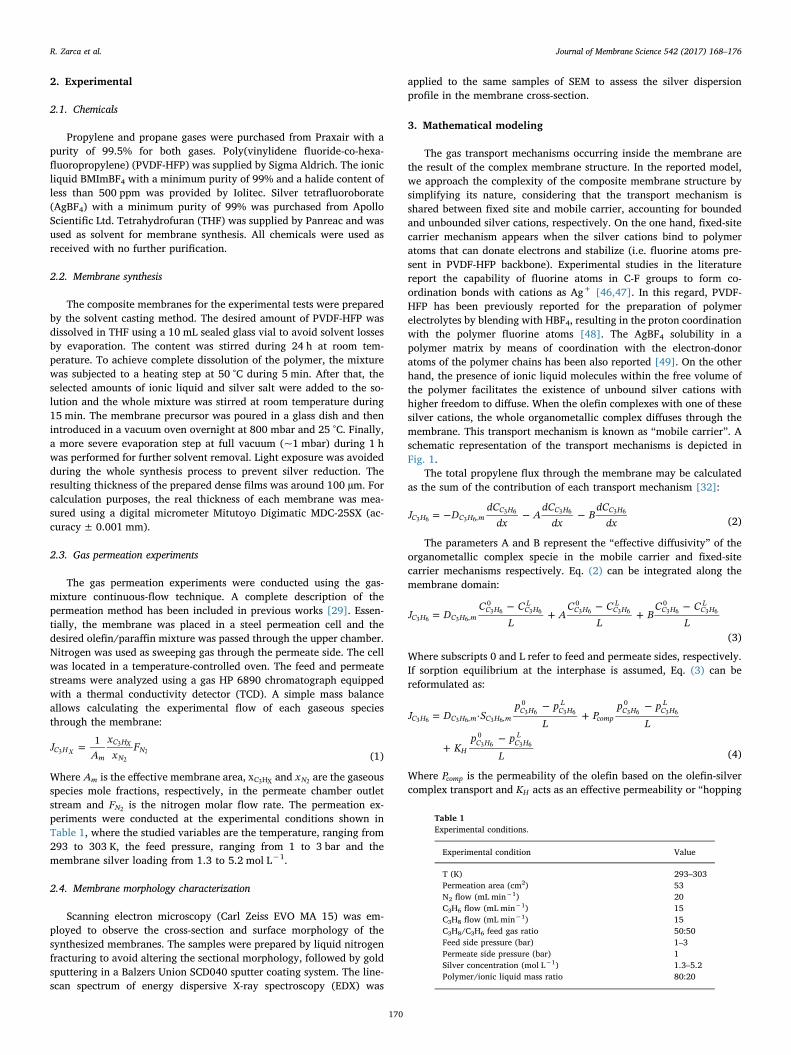
2. Experimental
2.1. Chemicals
Propylene and propane gases were purchased from Praxair with apurity of 99.5% for both gases. Poly(vinylidene fluoride-co-hexa-fluoropropylene) (PVDF-HFP) was supplied by Sigma Aldrich. The ionicliquid BMImBF4 with a minimum purity of 99% and a halide content ofless than 500 ppm was provided by Iolitec. Silver tetrafluoroborate(AgBF4) with a minimum purity of 99% was purchased from ApolloScientific Ltd. Tetrahydrofuran (THF) was supplied by Panreac and wasused as solvent for membrane synthesis. All chemicals were used asreceived with no further purification.
2.2. Membrane synthesis
The composite membranes for the experimental tests were preparedby the solvent casting method. The desired amount of PVDF-HFP wasdissolved in THF using a 10 mL sealed glass vial to avoid solvent lossesby evaporation. The content was stirred during 24 h at room tem-perature. To achieve complete dissolution of the polymer, the mixturewas subjected to a heating step at 50 °C during 5 min. After that, theselected amounts of ionic liquid and silver salt were added to the so-lution and the whole mixture was stirred at room temperature during15 min. The membrane precursor was poured in a glass dish and thenintroduced in a vacuum oven overnight at 800 mbar and 25 °C. Finally,a more severe evaporation step at full vacuum (~1 mbar) during 1 hwas performed for further solvent removal. Light exposure was avoidedduring the whole synthesis process to prevent silver reduction. Theresulting thickness of the prepared dense films was around 100 µm. Forcalculation purposes, the real thickness of each membrane was mea-sured using a digital micrometer Mitutoyo Digimatic MDC-25SX (ac-curacy± 0.001 mm).
2.3. Gas permeation experiments
The gas permeation experiments were conducted using the gas-mixture continuous-flow technique. A complete description of thepermeation method has been included in previous works [29]. Essen-tially, the membrane was placed in a steel permeation cell and thedesired olefin/paraffin mixture was passed through the upper chamber.Nitrogen was used as sweeping gas through the permeate side. The cellwas located in a temperature-controlled oven. The feed and permeatestreams were analyzed using a gas HP 6890 chromatograph equippedwith a thermal conductivity detector (TCD). A simple mass balanceallows calculating the experimental flow of each gaseous speciesthrough the membrane:
=JA
xx
F1C H
m
C H
NNX
X3
3
22 (1)
Where Am is the effective membrane area, xC H3 X and xN2 are the gaseousspecies mole fractions, respectively, in the permeate chamber outletstream and FN2 is the nitrogen molar flow rate. The permeation ex-periments were conducted at the experimental conditions shown inTable 1, where the studied variables are the temperature, ranging from293 to 303 K, the feed pressure, ranging from 1 to 3 bar and themembrane silver loading from 1.3 to 5.2 mol L−1.
2.4. Membrane morphology characterization
Scanning electron microscopy (Carl Zeiss EVO MA 15) was em-ployed to observe the cross-section and surface morphology of thesynthesized membranes. The samples were prepared by liquid nitrogenfracturing to avoid altering the sectional morphology, followed by goldsputtering in a Balzers Union SCD040 sputter coating system. The line-scan spectrum of energy dispersive X-ray spectroscopy (EDX) was
applied to the same samples of SEM to assess the silver dispersionprofile in the membrane cross-section.
3. Mathematical modeling
The gas transport mechanisms occurring inside the membrane arethe result of the complex membrane structure. In the reported model,we approach the complexity of the composite membrane structure bysimplifying its nature, considering that the transport mechanism isshared between fixed site and mobile carrier, accounting for boundedand unbounded silver cations, respectively. On the one hand, fixed-sitecarrier mechanism appears when the silver cations bind to polymeratoms that can donate electrons and stabilize (i.e. fluorine atoms pre-sent in PVDF-HFP backbone). Experimental studies in the literaturereport the capability of fluorine atoms in C-F groups to form co-ordination bonds with cations as Ag+ [46,47]. In this regard, PVDF-HFP has been previously reported for the preparation of polymerelectrolytes by blending with HBF4, resulting in the proton coordinationwith the polymer fluorine atoms [48]. The AgBF4 solubility in apolymer matrix by means of coordination with the electron-donoratoms of the polymer chains has been also reported [49]. On the otherhand, the presence of ionic liquid molecules within the free volume ofthe polymer facilitates the existence of unbound silver cations withhigher freedom to diffuse. When the olefin complexes with one of thesesilver cations, the whole organometallic complex diffuses through themembrane. This transport mechanism is known as “mobile carrier”. Aschematic representation of the transport mechanisms is depicted inFig. 1.
The total propylene flux through the membrane may be calculatedas the sum of the contribution of each transport mechanism [32]:
= − − −J DdC
dxA
dCdx
BdC
dxC H C H mC H C H C H
,3 6 3 63 6 3 6 3 6
(2)
The parameters A and B represent the “effective diffusivity” of theorganometallic complex specie in the mobile carrier and fixed-sitecarrier mechanisms respectively. Eq. (2) can be integrated along themembrane domain:
=−
+−
+−
J DC C
LA
C CL
BC C
LC H C H mC H C H
LC H C H
LC H C H
L
,
0 0 0
3 6 3 63 6 3 6 3 6 3 6 3 6 3 6
(3)
Where subscripts 0 and L refer to feed and permeate sides, respectively.If sorption equilibrium at the interphase is assumed, Eq. (3) can bereformulated as:
=−
+−
+−
J D Sp p
LP
p p
L
Kp p
L
·C H C H m C H mC H C H
L
compC H C H
L
HC H C H
L
, ,
0 0
0
3 6 3 6 3 63 6 3 6 3 6 3 6
3 6 3 6
(4)
Where Pcomp is the permeability of the olefin based on the olefin-silvercomplex transport and KH acts as an effective permeability or “hopping
Table 1Experimental conditions.
Experimental condition Value
T (K) 293–303Permeation area (cm2) 53N2 flow (mL min−1) 20C3H6 flow (mL min−1) 15C3H8 flow (mL min−1) 15C3H8/C3H6 feed gas ratio 50:50Feed side pressure (bar) 1–3Permeate side pressure (bar) 1Silver concentration (mol L−1) 1.3–5.2Polymer/ionic liquid mass ratio 80:20
R. Zarca et al. Journal of Membrane Science 542 (2017) 168–176
170
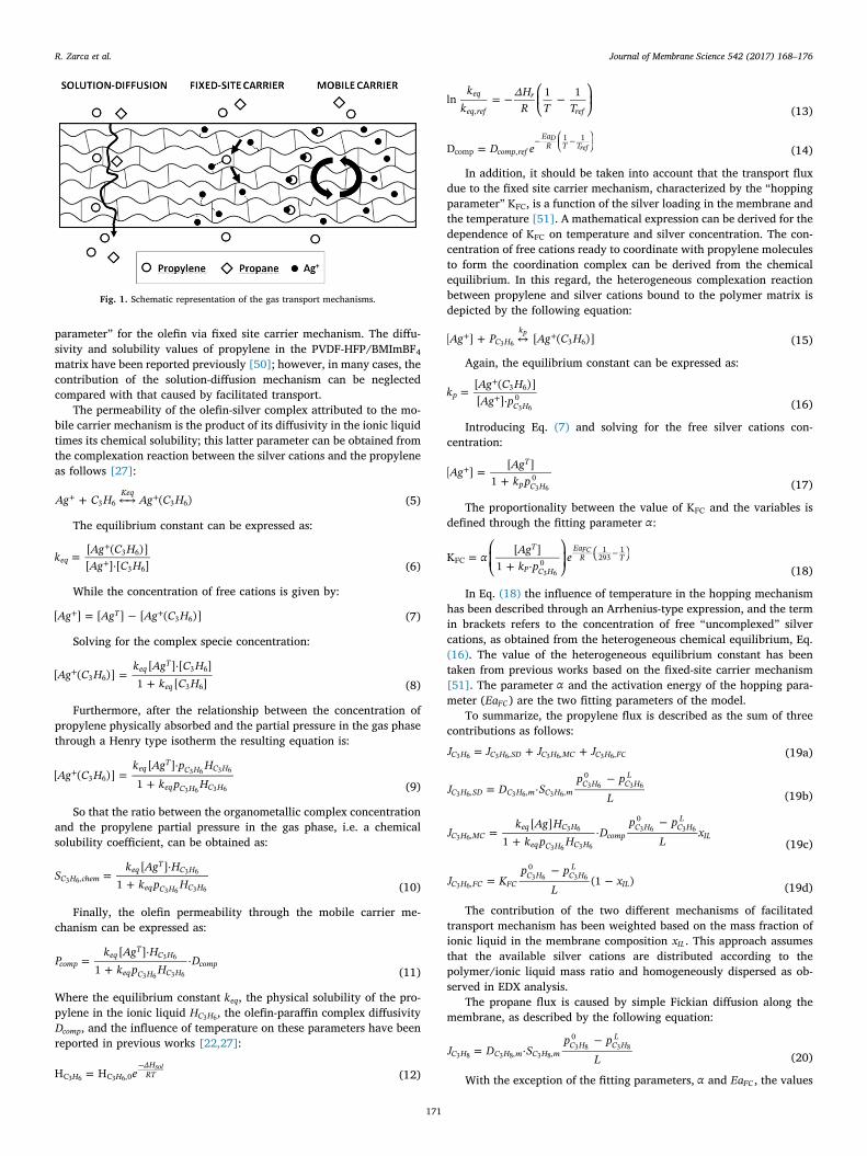
parameter” for the olefin via fixed site carrier mechanism. The diffu-sivity and solubility values of propylene in the PVDF-HFP/BMImBF4matrix have been reported previously [50]; however, in many cases, thecontribution of the solution-diffusion mechanism can be neglectedcompared with that caused by facilitated transport.
The permeability of the olefin-silver complex attributed to the mo-bile carrier mechanism is the product of its diffusivity in the ionic liquidtimes its chemical solubility; this latter parameter can be obtained fromthe complexation reaction between the silver cations and the propyleneas follows [27]:
+ ←→+ +Ag C H Ag C H( )Keq
3 6 3 6 (5)
The equilibrium constant can be expressed as:
=⋅
+
+kAg C HAg C H
[ ( )][ ] [ ]eq
3 6
3 6 (6)
While the concentration of free cations is given by:
= −+ +Ag Ag Ag C H[ ] [ ] [ ( )]T3 6 (7)
Solving for the complex specie concentration:
=⋅
++Ag C H
k Ag C Hk C H
[ ( )][ ] [ ]
1 [ ]eq
T
eq3 6
3 6
3 6 (8)
Furthermore, after the relationship between the concentration ofpropylene physically absorbed and the partial pressure in the gas phasethrough a Henry type isotherm the resulting equation is:
=⋅
++Ag C H
k Ag p Hk p H
[ ( )][ ]
1eq
TC H C H
eq C H C H3 6
3 6 3 6
3 6 3 6 (9)
So that the ratio between the organometallic complex concentrationand the propylene partial pressure in the gas phase, i.e. a chemicalsolubility coefficient, can be obtained as:
=⋅
+S
k Ag Hk p H[ ]
1C H chemeq
TC H
eq C H C H,3 6
3 6
3 6 3 6 (10)
Finally, the olefin permeability through the mobile carrier me-chanism can be expressed as:
=⋅
+P
k Ag Hk p H
D[ ]
1·comp
eqT
C H
eq C H C Hcomp
3 6
3 6 3 6 (11)
Where the equilibrium constant keq, the physical solubility of the pro-pylene in the ionic liquid HC H3 6, the olefin-paraffin complex diffusivityDcomp, and the influence of temperature on these parameters have beenreported in previous works [22,27]:
=−
eH HH HΔHRTC C ,0
sol3 6 3 6 (12)
⎜ ⎟= − ⎛⎝
− ⎞⎠
kk
ΔHR T T
ln 1 1eq
eq ref
r
ref, (13)
=⎜ ⎟− ⎛⎝
− ⎞⎠D eD comp ref
EaR T T
comp ,
1 1Dref (14)
In addition, it should be taken into account that the transport fluxdue to the fixed site carrier mechanism, characterized by the “hoppingparameter” KFC, is a function of the silver loading in the membrane andthe temperature [51]. A mathematical expression can be derived for thedependence of KFC on temperature and silver concentration. The con-centration of free cations ready to coordinate with propylene moleculesto form the coordination complex can be derived from the chemicalequilibrium. In this regard, the heterogeneous complexation reactionbetween propylene and silver cations bound to the polymer matrix isdepicted by the following equation:
+ ↔+ +Ag P Ag C H[ ] [ ( )]C Hk
3 6p
3 6 (15)
Again, the equilibrium constant can be expressed as:
=⋅
+
+kAg C HAg p
[ ( )][ ]p
C H
3 603 6 (16)
Introducing Eq. (7) and solving for the free silver cations con-centration:
=+
+AgAgk p
[ ][ ]
1
T
p C H03 6 (17)
The proportionality between the value of KFC and the variables isdefined through the fitting parameter α:
= ⎛
⎝⎜ +
⎞
⎠⎟
−( )αAgk p
eK[ ]
1 ·
T
P C H
EaR TFC 0
1293
1FC
3 6 (18)
In Eq. (18) the influence of temperature in the hopping mechanismhas been described through an Arrhenius-type expression, and the termin brackets refers to the concentration of free “uncomplexed” silvercations, as obtained from the heterogeneous chemical equilibrium, Eq.(16). The value of the heterogeneous equilibrium constant has beentaken from previous works based on the fixed-site carrier mechanism[51]. The parameter α and the activation energy of the hopping para-meter (EaFC) are the two fitting parameters of the model.
To summarize, the propylene flux is described as the sum of threecontributions as follows:
= + +J J J JC H C H SD C H MC C H FC, , ,3 6 3 6 3 6 3 6 (19a)
=−
J D Sp p
L·C H SD C H m C H m
C H C HL
, , ,
0
3 6 3 6 3 63 6 3 6
(19b)
=+
−J
k Ag Hk p H
Dp p
Lx
[ ]1
·C H MCeq C H
eq C H C Hcomp
C H C HL
IL,
0
3 63 6
3 6 3 6
3 6 3 6
(19c)
=−
−J Kp p
Lx(1 )C H FC FC
C H C HL
IL,
0
3 63 6 3 6
(19d)
The contribution of the two different mechanisms of facilitatedtransport mechanism has been weighted based on the mass fraction ofionic liquid in the membrane composition xIL. This approach assumesthat the available silver cations are distributed according to thepolymer/ionic liquid mass ratio and homogeneously dispersed as ob-served in EDX analysis.
The propane flux is caused by simple Fickian diffusion along themembrane, as described by the following equation:
=−
J D Sp p
L·C H C H m C H m
C H C HL
, ,
0
3 8 3 8 3 83 8 3 8
(20)
With the exception of the fitting parameters, α and EaFC, the values
Fig. 1. Schematic representation of the gas transport mechanisms.
R. Zarca et al. Journal of Membrane Science 542 (2017) 168–176
171

of model parameters have been extracted from previous works. In thecase of mobile carrier, the values of the organometallic complex dif-fusivity and its dependence on temperature were taken from an ex-perimental study on supported ionic liquid membranes (SILMs). Thesemembranes where synthesized introducing the BMImBF4/AgBF4 mix-ture in the pores of a hydrophilic PVDF support [22]. The value of theequilibrium constant for the complexation reaction, the propylene so-lubility in the ionic liquid, and their enthalpies were extracted fromabsorption equilibria of propylene in ionic liquid/Ag+ solutions [27].The value of the heterogeneous equilibrium constant was calculated ina previous study on fixed site carrier mechanism [51].
It is worth noticing that the values of the estimated parameters aredependent on the chemical nature of the involved species (permeantgas, polymer, carrier and ionic liquid) and the interactions betweenthem. As a result, the procedure to implement this model in similarhybrid systems implies the use of case-specific model parameters andthe estimation of a new pair of values for both α and EaFC.
4. Results and discussion
4.1. Membrane morphology
Fig. 2 shows the cross-section and surface of a PVDF-HFP mem-brane, a PVDF-HFP/BMImBF4 membrane and a composite PVDF-HFP/BMImBF4/AgBF4. The cross-section micrographs show a non-poroushomogenous structure without cavities or voids in all three cases. Thereis no evidence of pure ionic liquid domains in membranes B and C,proving the complete mixture between the ionic liquid and thepolymer. Furthermore, the addition of the silver salt in membrane Cdoes not modify the structure but maintains the original dense andhomogeneous pattern.
Further knowledge on membrane structure can be extracted fromthe EDX analysis. EDX makes use of x-ray spectrum emitted by the solidsample bombarded with a focused beam of electrons to obtain a loca-lized chemical analysis. When the sample is hit by the electron beam,electrons are ejected from the atoms of the sample's surface. The re-sulting electron vacancies are filled by electrons from a higher energy
state, and an x-ray is emitted to balance the energy difference betweenthe two electrons' states. The x-ray energy is characteristic of the ele-ment from which it was emitted.
In this work, EDX was used in conjunction with SEM to obtain scan-lines and plot-mapping patterns of elemental silver on cross-sectionalimages of the composite membrane. The energy dispersive x-ray spec-troscopy patterns shown in Fig. 3 confirm that no ionic aggregates orsilver particles are formed inside the membrane, which is in goodagreement with the previous discussion on silver salt dissolution. Thus,the silver is homogeneously dispersed along the membrane thicknesswith no layers of preferential accumulation.
4.2. Permeation results
Table 2 displays the experimental performance of the compositemembranes assessed in this work. The experimental effective perme-ability has been calculated normalizing the experimental flux with themembrane thickness and the partial pressure gradient, as shown in Eq.(21).
=P J LΔpC H C H
C HX X
X3 3
3 (21)
Facilitated transport phenomena yielded remarkably high values ofpropylene permeability. On the other hand, the composite materialcauses very low propane permeability, as it is only due to Fickian dif-fusion. As a result, the membrane provides remarkably high separationselectivity values. The results show that the propane permeability suf-fers a slight increase as the silver loading rises. Although the behaviorof the paraffin is unusual, similar behavior has been observed in someprevious studies, such as those reported by Kim et al. [52] and SuryaMurali et al. [53].
Fig. 4 depicts the influence of the feed partial pressure on the ex-perimental olefin flux. As the partial pressure gradient offers the drivingforce of the separation process, it has a direct effect on the propyleneflux. Nonetheless, the composite membrane performs high olefin fluxeseven at the lower assessed partial pressures, forecasting its suitabilityfor the separation of other olefin/paraffin mixtures with minor presence
Fig. 2. Cross-section and surface morphology of: A) PVDF-HFP membrane B) PVDF-HFP/BMImBF4 membrane, C) PVDF-HFP/BMImBF4/AgBF4 5.2 mol/L.
R. Zarca et al. Journal of Membrane Science 542 (2017) 168–176
172
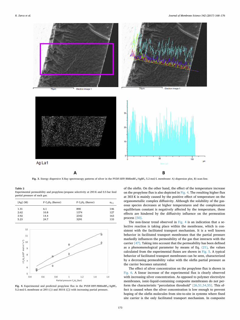
of the olefin. On the other hand, the effect of the temperature increaseon the propylene flux is also depicted in Fig. 4. The resulting higher fluxat 303 K is mainly caused by the positive effect of temperature on theorganometallic complex diffusivity. Although the solubility of the gas-eous species decreases at higher temperatures and the complexationequilibrium constant is negatively affected by the temperature, theseeffects are hindered by the diffusivity influence on the permeationprocess [50].
The non-linear trend observed in Fig. 4 is an indication that a se-lective reaction is taking place within the membrane, which is con-sistent with the facilitated transport mechanism. It is a well knownbehavior in facilitated transport membranes that the partial pressuremarkedly influences the permeability of the gas that interacts with thecarrier [47]. Taking into account that the permeability has been definedas a phenomenological parameter by means of Eq. (21), the valuescalculated from the experimental fluxes are shown in Fig. 5. A typicalbehavior of facilitated transport membranes can be seen, characterizedby a decreasing permeability value with the olefin partial pressure asthe carrier becomes saturated.
The effect of silver concentration on the propylene flux is shown inFig. 6. A linear increase of the experimental flux is clearly observedwith increasing silver concentration. As opposed to polymer electrolytemembranes, ionic-liquid-containing composite membranes do not per-form the characteristic “percolation threshold” [26,51,54,55]. This ef-fect is caused when the silver concentration is low enough to preventhoping of the olefin molecules from site-to-site in systems where fixedsite carrier is the only facilitated transport mechanism. In composite
Fig. 3. Energy dispersive X-Ray spectroscopy patterns of silver in the PVDF-HFP/BMImBF4/AgBF4 5.2 mol/L membrane: A) dispersion plot, B) scan-line.
Table 2Experimental permeability and propylene/propane selectivity at 293 K and 0.5 bar feedpartial pressure of each gas.
[Ag] (M) P C3H8 (Barrer) P C3H6 (Barrer) αi/j
1.31 6.1 890 1462.62 10.8 1374 1273.92 14.4 2342 1635.23 24.7 3291 133
Fig. 4. Experimental and predicted propylene flux in the PVDF-HFP/BMImBF4/AgBF45.2 mol/L membrane at 293 (○) and 303 K (□) with increasing partial pressure.
R. Zarca et al. Journal of Membrane Science 542 (2017) 168–176
173
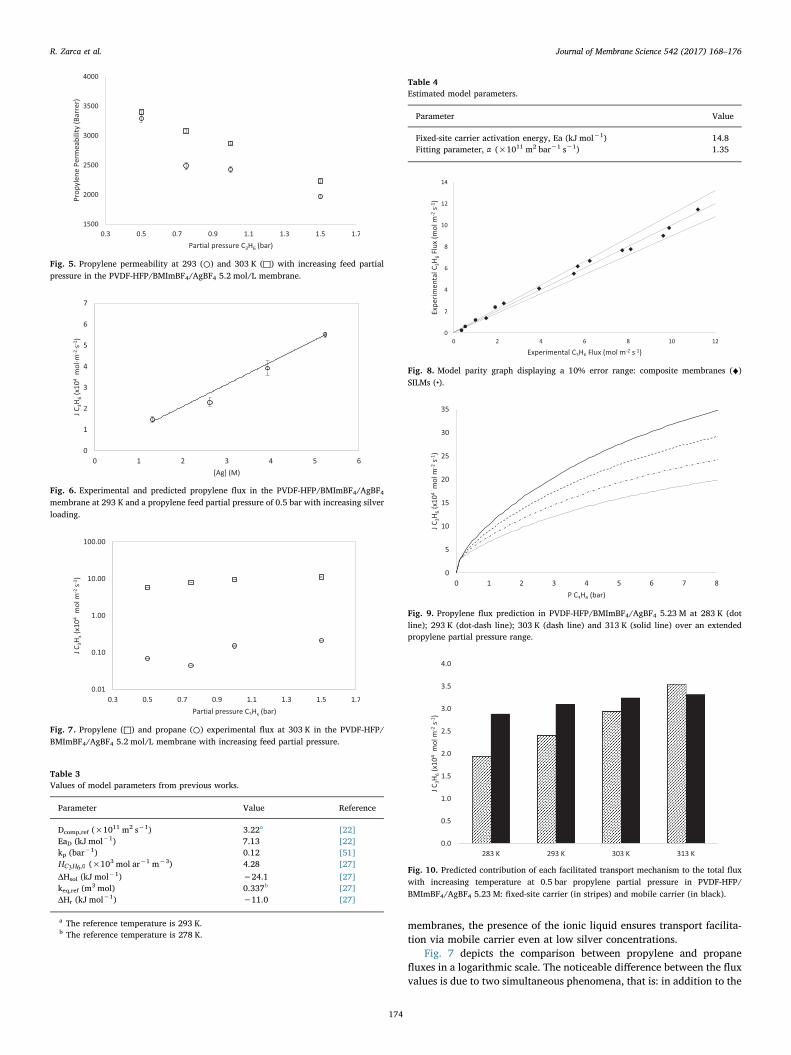
membranes, the presence of the ionic liquid ensures transport facilita-tion via mobile carrier even at low silver concentrations.
Fig. 7 depicts the comparison between propylene and propanefluxes in a logarithmic scale. The noticeable difference between the fluxvalues is due to two simultaneous phenomena, that is: in addition to the
Fig. 5. Propylene permeability at 293 (○) and 303 K (□) with increasing feed partialpressure in the PVDF-HFP/BMImBF4/AgBF4 5.2 mol/L membrane.
Fig. 6. Experimental and predicted propylene flux in the PVDF-HFP/BMImBF4/AgBF4membrane at 293 K and a propylene feed partial pressure of 0.5 bar with increasing silverloading.
Fig. 7. Propylene (□) and propane (○) experimental flux at 303 K in the PVDF-HFP/BMImBF4/AgBF4 5.2 mol/L membrane with increasing feed partial pressure.
Table 3Values of model parameters from previous works.
Parameter Value Reference
Dcomp,ref (×1011 m2 s−1) 3.22a [22]EaD (kJ mol−1) 7.13 [22]kp (bar−1) 0.12 [51]HC H3 6,0 (×103 mol ar−1 m−3) 4.28 [27]ΔHsol (kJ mol−1) −24.1 [27]keq,ref (m3 mol) 0.337b [27]ΔHr (kJ mol−1) −11.0 [27]
a The reference temperature is 293 K.b The reference temperature is 278 K.
Table 4Estimated model parameters.
Parameter Value
Fixed-site carrier activation energy, Ea (kJ mol−1) 14.8Fitting parameter, α (×1011 m2 bar−1 s−1) 1.35
Fig. 8. Model parity graph displaying a 10% error range: composite membranes (♦)SILMs (•).
Fig. 9. Propylene flux prediction in PVDF-HFP/BMImBF4/AgBF4 5.23 M at 283 K (dotline); 293 K (dot-dash line); 303 K (dash line) and 313 K (solid line) over an extendedpropylene partial pressure range.
Fig. 10. Predicted contribution of each facilitated transport mechanism to the total fluxwith increasing temperature at 0.5 bar propylene partial pressure in PVDF-HFP/BMImBF4/AgBF4 5.23 M: fixed-site carrier (in stripes) and mobile carrier (in black).
R. Zarca et al. Journal of Membrane Science 542 (2017) 168–176
174
facilitated transport of propylene, the PVDF-HFP crystallinity reducesthe paraffin physical solubility, yielding very low flux via conventionalsolution-diffusion [45]. As a result, permeability selectivities higherthan 150 are achieved, which satisfy the requirements for most of theindustrial applications.
4.3. Model results
The model parameters taken from previous experimental studies areshown in Table 3. The proposed model has two estimated parameters:the fitting parameter α, and the fixed site carrier activation energyEaFC. Model regression to experimental data for each specific case studyis needed in order to determine the values of these parameters. AspenCustom Modeler software was employed in this work for estimationtasks. The resulting values of the fitting parameters for this particularcase study are displayed in Table 4.
Once the fitting parameters are obtained, the model is able to de-scribe the system performance providing that the input data are withinthe studied range. Figs. 4 and 6 compare the model predicted values toexperimental data and prove the model accuracy to simulate thetransmembrane flux for changing temperature, feed pressure and silverloading. The model values have been plotted against the experimentaldata to build the model parity graph, displaying a 10% error range,Fig. 8. Besides, this generalized model is also capable of simulating theperformance of SILMs when the fixed-site carrier contribution is ne-glected; in order to confirm this possibility, the parity graph includesthe experimental and model results of supported ionic liquid mem-branes (SILMs) reported in previous works [22]. It can be seen that themajority of the points fall within the acceptable error interval, sug-gesting an accurate fitting between the experimentally obtained valuesand the model calculations.
With aim at the model application, it is also possible to extrapolatethe model calculations out of the range of the studied variables, whiletaking into account the possible deviations associated with the extra-polation method. In this manner, the present model is a useful pre-dictive tool to calculate the transmembrane flux in composite mem-branes performing a hybrid mobile/fixed carrier gas transportmechanisms. Fig. 9 shows the predicted propylene flux in a wide rangeof propylene feed partial pressures and four temperatures for thehighest silver loading assessed in this work. The values at pressuresoutside the 0.5–1.5 bar interval and at 283 and 313 K are model ex-trapolations. Process design and decision-making using compositemembranes could be improved implementing the proposed mathema-tical expressions to predict the material performance.
Finally, with the model, it is possible to calculate the contribution ofthe individual facilitated transport mechanisms to the total flux, asshown in Fig. 10. The contribution of the solution-diffusion mechanismhas been neglected because it represents less than 1% of the total flux inall cases. Note that the values at 283 K and 313 K have been extra-polated. The results show that, although the flux always shows an in-creasing trend with temperature, this variable has a greater effect onthe fixed-site carrier mechanism compared to the mobile carrier. Thisbehavior is explained through the negative effect of temperature on thesolubility term in the mobile carrier contribution.
5. Conclusions
A novel mathematical model able to describe the facilitated trans-port of propylene in composite membranes is reported. The model takesinto account the different transport mechanisms featured in polymer/ionic-liquid/carrier systems, namely, solution-diffusion, fixed-site car-rier and mobile carrier transport, describing the total gas flux as thesum of the contributions by each mechanism.
In order to check the suitability of the model simulated resultswhere compared to experimental data obtained working with PVDF-HFP/BMImBF4/AgBF4 membranes in continuous-flow gas-mixture
permeation tests, varying the temperature, silver loading and feedpressure. It has been checked that the addition of BMImBF4 ionic liquid,which makes the membranes differ from solid state polymer electrolytemembranes, avoids the characteristic “percolation threshold” phe-nomena and allows transport facilitation even at low carrier con-centration.
The model needs two fitting parameters α=1.35×10⁻¹¹ m2 bar−1 s−1 and Ea = 14.8 kJ mol−1 that are case-sen-sitive depending on the chemical nature of the species (olefin, polymer,silver salt, ionic liquid) and their interactions. The reported model be-comes a useful tool to predict the transmembrane flux via facilitatedtransport in those systems featuring fixed-site carrier and mobile carriermechanisms simultaneously. In this regard, it will allow further designand optimization of more efficient membrane configurations.
Acknowledgement
Financial support from projects CTQ2015-66078-R and CTQ2016-75158-R (MINECO, Spain-FEDER 2014–2020) is gratefully acknowl-edged. Raúl Zarca also thanks the Universidad de Cantabria for apostgraduate fellowship.
References
[1] D.S. Sholl, R.P. Lively, Seven chemical separations to change the world, Nature 532(2016) 6–8.
[2] J.C. Charpentier, In the frame of globalization and sustainability, process in-tensification, a path to the future of chemical and process engineering (moleculesinto money), Chem. Eng. J. 134 (2007) 84–92.
[3] O.M. Ilinitch, G.L. Semin, M.V. Chertova, K.I. Zamaraev, Novel polymeric mem-branes for separation of hydrocarbons, J. Memb. Sci. 66 (1992) 1–8.
[4] K. Okamoto, A. Taguchi, J. Hao, K. Tanaka, H. Kita, Permeation and separationproperties of polyimide membranes to olefins and paraffins, J. Memb. Sci. 121(1996) 197–207.
[5] A. Ito, S.-T. Hwang, Permeation of propane and propylene thrugh cellulosicpolymer membranes, J. Appl. Polym. Sci. 38 (1989) 483–490.
[6] R. Faiz, K. Li, Polymeric membranes for light olefin/paraffin separation,Desalination 287 (2012) 82–97.
[7] R.J. Swaidan, X. Ma, E. Litwiller, I. Pinnau, Enhanced propylene/propane separa-tion by thermal annealing of an intrinsically microporous hydroxyl-functionalizedpolyimide membrane, J. Memb. Sci. 495 (2015) 235–241.
[8] K.S. Liao, J.Y. Lai, T.S. Chung, Metal ion modified PIM-1 and its application forpropylene/propane separation, J. Memb. Sci. 515 (2016) 36–44.
[9] V.F.D. Martins, A.M. Ribeiro, A. Ferreira, U.H. Lee, Y.K. Hwang, J.S. Chang,J.M. Loureiro, A.E. Rodrigues, Ethane/ethylene separation on a copper benzene-1,3,5-tricarboxylate MOF, Sep. Purif. Technol. 149 (2015) 445–456.
[10] M. Hartmann, U. Böhme, M. Hovestadt, C. Paula, Adsorptive Separation of Olefin/Paraffin Mixtures with ZIF-4, Langmuir 31 (2015) 12382–12389.
[11] O. Salinas, X. Ma, Y. Wang, Y. Han, I. Pinnau, Carbon molecular sieve membranefrom a microporous spirobisindane-based polyimide precursor with enhancedethylene/ethane mixed-gas selectivity, RSC Adv. 7 (2017) 3265–3272.
[12] R.J. Swaidan, X. Ma, I. Pinnau, Spirobisindane-based polyimide as efficient pre-cursor of thermally-rearranged and carbon molecular sieve membranes for en-hanced propylene/propane separation, J. Memb. Sci. 520 (2016) 983–989.
[13] H.-X. Sun, B.-B. Yuan, P. Li, T. Wang, Y.-Y. Xu, Preparation of nanoporous grapheneand the application of its nanocomposite membrane in propylene/propane se-paration, Funct. Mater. Lett. 8 (2015) 1550019.
[14] I. Pinnau, L.G. Toy, Solid polymer electrolyte composite membranes for olefin/paraffin separation, J. Memb. Sci. 184 (2001) 39–48.
[15] D.J. Safarik, R.B. Eldridge, Olefin/Paraffin Separations by Reactive Absorption: aReview, Ind. Eng. Chem. Res. 37 (1998) 2571–2581.
[16] A. Ortiz, L.M. Galán, D. Gorri, A.B. De Haan, I. Ortiz, Kinetics of reactive absorptionof propylene in RTIL-Ag+ media, Sep. Purif. Technol. 73 (2010) 106–113.
[17] M. Teramoto, H. Matsuyama, T. Yamashiro, Y. Katayama, Separation of ethylenefrom ethane by supported liquid membranes containing silver-nitrate as a carrier, J.Chem. Eng. Jpn. 19 (1986) 419–424.
[18] S. Duan, A. Ito, A. Ohkawa, Separation of propylene/propane mixture by a sup-ported liquid membrane containing triethylene glycol and a silver salt, J. Memb.Sci. 215 (2003) 53–60.
[19] G. Zarca, I. Ortiz, A. Urtiaga, Copper(I)-containing supported ionic liquid mem-branes for carbon monoxide/nitrogen separation, J. Memb. Sci. 438 (2013) 38–45.
[20] M.T. Ravanchi, T. Kaghazchi, A. Kargari, Supported liquid membrane separation ofpropylene-propane mixtures using a metal ion carrier, Desalination 250 (2010)130–135.
[21] D. Gorri, M. Fallanza, A. Ortiz, I. Ortiz, Supported liquid membranes for perva-poration processes, Ref. Modul. Chem. Mol. Sci. Chem. Eng. (2017).
[22] M. Fallanza, A. Ortiz, D. Gorri, I. Ortiz, Experimental study of the separation ofpropane/propylene mixtures by supported ionic liquid membranes containing
R. Zarca et al. Journal of Membrane Science 542 (2017) 168–176
175

Ag+–RTILs as carrier, Sep. Purif. Technol. 97 (2012) 83–89.[23] T. Welton, Room-temperature ionic liquids. solvents for synthesis and catalysis,
Chem. Rev. 99 (1999) 2071–2083.[24] J.P. Hallett, T. Welton, Room-temperature ionic liquids: solvents for synthesis and
catalysis. 2, Chem. Rev. 111 (2011) 3508–3576.[25] R. Faiz, K. Li, Olefin/paraffin separation using membrane based facilitated trans-
port/chemical absorption techniques, Chem. Eng. Sci. 73 (2012) 261–284.[26] J.H. Kim, S.W. Kang, Y.S. Kang, Threshold silver concentration for facilitated olefin
transport in polymer/silver salt membranes, J. Polym. Res. 19 (2012).[27] A. Ortiz, A. Ruiz, D. Gorri, I. Ortiz, Room temperature ionic liquid with silver salt as
efficient reaction media for propylene/propane separation: absorption equilibrium,Sep. Purif. Technol. 63 (2008) 311–318.
[28] A. Ortiz, L. Galán, D. Gorri, B. De Haan, I. Ortiz, Reactive ionic liquid media for theseparation of propylene / propane gaseous mixtures, Ind. Eng. Chem. Res. 49(2010) 7227–7233.
[29] M. Fallanza, A. Ortiz, D. Gorri, I. Ortiz, Polymer-ionic liquid composite membranesfor propane/propylene separation by facilitated transport, J. Memb. Sci. 444 (2013)164–172.
[30] L.C. Tomé, D. Mecerreyes, C.S.R. Freire, L.P.N. Rebelo, I.M. Marrucho, Polymericionic liquid membranes containing IL–Ag+ for ethylene/ethane separation viaolefin-facilitated transport, J. Mater. Chem. A 2 (2014) 5631.
[31] R.D. Noble, Facilitated transport with fixed-site carrier membranes, J. Chem. Soc.,Faraday Trans. 87 (1991) 2089–2092.
[32] R.D. Noble, Generalized microscopic mechanism of facilitated transport in fixed sitecarrier membranes, J. Memb. Sci. 75 (1992) 121–129.
[33] S. Najari, S.S. Hosseini, M. Omidkhah, N.R. Tan, Phenomenological modeling andanalysis of gas transport in polyimide membranes for propylene/propane separa-tion, RSC Adv. 5 (2015) 47199–47215.
[34] S. Sridhar, A.A. Khan, Simulation studies for the separation of propylene and pro-pane by ethylcellulose membrane, J. Memb. Sci. 1 (159) (1999) 209–219.
[35] M.T. Castoldi, Modeling of the Separation of Propene / Propane Mixtures byPermeation through Membranes in a Polymerization System, 2007, pp. 1259–1269.
[36] M. Ohyanagi, H. Nishide, K. Suenaga, E. Tsuchida, Effect of polymer matrix andmetal species on facilitated oxygen transport in metalloporphyrin (Oxygen Carrier)fixed membranes, Macromolecules 21 (1988) 1590–1594.
[37] T. Suzuki, Y. Soejima, H. Nishide, E. Tsuchida, Effect of an oxygen-binding reactionat the cobalt porphyrin site fixed in a polymer membrane on facilitated oxygentransport, Bull. Chem. Soc. Jpn. 68 (1995) 1036–1041.
[38] D.R. Smith, J.A. Quinn, The facilitated transport of carbon monoxide through cu-prous chloride solutions, AIChE J. 26 (1980) 112–120.
[39] R.D. Noble, Analysis of facilitated carrier membranes transport with fixed site, J.Memb. Sci 50 (1990) 207–214.
[40] Y.S. Kang, J.M. Hong, J. Jang, U.Y. Kim, Analysis of facilitated transport in solidmembranes with fixed site carriers: 1. Single RC circuit model, J. Memb. Sci. 109(1996) 149–157.
[41] J.M. Hong, Y.S. Kang, J. Jang, U.Y. Kim, Analysis of facilitated transport in
polymeric membrane with fixed site carrier: 2. Series RC circuit model, J. Memb.Sci. 109 (1996) 159–163.
[42] W.J. Ward, Analytical and experimental studies of facilitated transport, AIChE J. 16(1970) 405–410.
[43] B.M. Johnson, R.W. Baker, S.L. Matson, K.L. Smith, I.C. Roman, M.E. Tuttle,H.K. Lonsdale, Liquid membranes for the production of oxygen-enriched air. II.Facilitated-transport membranes, J. Memb. Sci. 31 (1987) 31–67.
[44] M. Fallanza, M. González-Miquel, E. Ruiz, A. Ortiz, D. Gorri, J. Palomar, I. Ortiz,Screening of RTILs for propane/propylene separation using COSMO-RS metho-dology, Chem. Eng. J. 220 (2013) 284–293.
[45] S. Abbrent, J. Plestil, D. Hlavata, J. Lindgren, J. Tegenfeldt, Å. Wendsjö,Crystallinity and morphology of PVdF–HFP-based gel electrolytes, Polymer 42(2001) 1407–1416.
[46] H. Plenio, R. Diodone, Coordination chemistry with CF Units as B Donors: Ag+
complexes of partially fluorinated crown ethers with direct metal-fluorine interac-tions, Chem. Ber. 129 (1996) 1211–1217.
[47] P.K. Sazonov, L.K. Minacheva, A.V. Churakov, V.S. Sergienko, G. a Artamkina,Y.F. Oprunenko, I.P. Beletskaya, Lariat ethers with fluoroaryl side-arms: a study ofCFmetal cation interaction in the complexes of N-(o-fluoroaryl)azacrown ethers,Dalton Trans. (2009) 843–850.
[48] J. Chang, S.W. Kang, CO2 separation through poly(vinylidene fluoride-co-hexa-fluoropropylene) membrane by selective ion channel formed by tetrafluoroboricacid, Chem. Eng. J. 306 (2016) 1189–1192.
[49] S. Sunderrajan, B.D. Freeman, C.K. Hall, I. Pinnau, Propane and propylene sorptionin solid polymer electrolytes based on poly(ethylene oxide) and silver salts, J.Memb. Sci. 182 (2001) 1–12.
[50] R. Zarca, A. Ortiz, D. Gorri, I. Ortiz, Facilitated transport of propylene throughcomposite polymer-ionic liquid membranes. mass transfer analysis, Chem. Prod.Process Model. 11 (2016) 77–81.
[51] R. Zarca, A. Ortiz, D. Gorri, I. Ortiz, A practical approach to fixed-site-carrier fa-cilitated transport modeling for the separation of propylene/propane mixturesthrough silver-containing polymeric membranes, Sep. Purif. Technol. 180 (2017)82–89.
[52] J.H. Kim, B.R. Min, J. Won, Y.S. Kang, Complexation mechanism of olefin withsilver ions dissolved in a polymer matrix and its effect on facilitated olefin trans-port, Chem. - A Eur. J. 8 (2002) 650–654.
[53] R. Surya Murali, K. Yamuna Rani, T. Sankarshana, A.F. Ismail, S. Sridhar,Separation of binary mixtures of propylene and propane by facilitated transportthrough silver incorporated Poly(Ether-Block-Amide) membranes, Oil Gas. Sci.Technol. – Rev. d′IFP Energ. Nouv. 70 (2015) 381–390.
[54] Y. Yoon, J. Won, Y.S. Kang, Polymer electrolyte membranes containing silver ionfor facilitated olefin transport, Macromolecules 33 (2000) 3185–3186.
[55] A. Morisato, Z. He, I. Pinnau, T.C. Merkel, Transport properties of PA12-PTMO/AgBF4 solid polymer electrolyte membranes for olefin/paraffin separation,Desalination 145 (2002) 347–351.
R. Zarca et al. Journal of Membrane Science 542 (2017) 168–176
176

Contents lists available at ScienceDirect
Journal of Membrane Science
journal homepage: www.elsevier.com/locate/memsci
Optimized distillation coupled with state-of-the-art membranes forpropylene purification
Raúl Zarcaa, Alfredo Ortiza, Daniel Gorria, Lorenz T. Bieglerb, Inmaculada Ortiza,⁎
a Department of Chemical and Biomolecular Engineering, University of Cantabria, Av. Los Castros 46, 39005 Santander, SpainbDepartment of Chemical Engineering, Carnegie-Mellon University, 5000 Forbes Avenue, Pittsburgh, PA 15213-3890, United States
A R T I C L E I N F O
Keywords:OptimizationPropylenePropaneHybrid distillationMembraneMathematical modelProcess intensification
A B S T R A C T
The growing production of polyolefins, mainly polyethylene and polypropylene, currently demands increasingoutputs of polymer-grade light olefins. The most commonly adopted process for the separation of olefin/paraffinmixtures is performed by energy intensive high pressure or cryogenic distillation, which is considered the mostexpensive operation in the petrochemical industry. The use of membrane technology offers a compact andmodular solution for capital and energy savings, thanks to process intensification. In this work, we move one stepforward in the design of hybrid propane/propylene separation systems, using computer aided modeling tools toidentify economically optimal combinations of distillation and state-of-the-art membranes. A model is proposedto optimize a hybrid configuration, whereby the membrane performs the bulk separation and the distillationcolumn is intended for the final product polishing, accounting for membrane investment cost and process op-erating expenses. The decision variables are the membrane area and the column reflux ratio, and the model isable to calculate the optimal feed trays. The upper-bound properties of selected membranes, which define theirperformance and reliability criteria, have been studied, benchmarking the economic evaluation against con-ventional distillation in order to assess the expedience of a hybrid system implementation.
1. Introduction
The use of ethylene and propylene as main building blocks for awide number of essential chemicals turns them into the most importantfeedstocks of the petrochemical industry. The separation of these lightolefins from their homologous paraffin entails a costly high pressure orcryogenic distillation with a prominent contribution to the worldwideenergy consumption [1]. Although major efforts have been carried outto develop alternative separation processes, mainly enhanced distilla-tions [2] and physical/chemical adsorptions [3,4], none of them havesucceeded in replacing traditional distillation.
Process intensification by means of membrane technology is one ofthe most promising strategies to overcome this handicap, performingthe separation at mild temperature and pressure conditions usingmodular and compact equipment [5]. A characteristic feature ofmembrane materials is the existing trade-off between the amount of gasthat passes though the film (i.e. permeability) and the selectivity to-wards the desired gaseous species. In addition, this effect can be a de-cisive factor for further industrial application.
Dense polymeric membranes, based exclusively on solution-diffu-sion transport, offer poor performance in terms of selectivity, and their
potential industrial application may be found in the recovery of un-reacted olefin after polymerization, where selectivity values of 3–5 maybe adequate [6,7]. The search for better separation capabilities has ledto the development of new materials that excel in olefin/paraffin se-paration applications. Carbon molecular sieves prepared through pyr-olysis of polymer precursors display a complex morphology combiningultramicropores and micropores, which are responsible for the mole-cular sieving and the solubility, respectively. These show propane/propylene selectivity values up to 50 and permeability values around 20barrer [8–10]. Zeolitic imidazolate framework (ZIF) membranes pre-sent a structure built upon metals with tetrahedral coordination geo-metries interlinked with imidazolate ligands, which separates themixture based on the differences in diffusivity through the pore system.These ceramic membranes perform selectivity values as high as 70 witha permeability ranging between 100 and 400 barrer [11–13]. Finally,facilitated transport membranes make use of silver cations as carrier,selectively transporting the olefin through the membrane and, reachinga selectivity higher than 100 with permeability values typically sur-passing 1000 barrer [14–16]. Additionally, the use of ionic liquids andsilver nanoparticles to enhance the performance and carrier stabilityhas been reported to produce favorable effects [17,18]. These
https://doi.org/10.1016/j.memsci.2018.04.016Received 8 February 2018; Received in revised form 5 April 2018; Accepted 10 April 2018
⁎ Corresponding author.E-mail address: [email protected] (I. Ortiz).
Journal of Membrane Science 556 (2018) 321–328
Available online 12 April 20180376-7388/ © 2018 Elsevier B.V. All rights reserved.
T
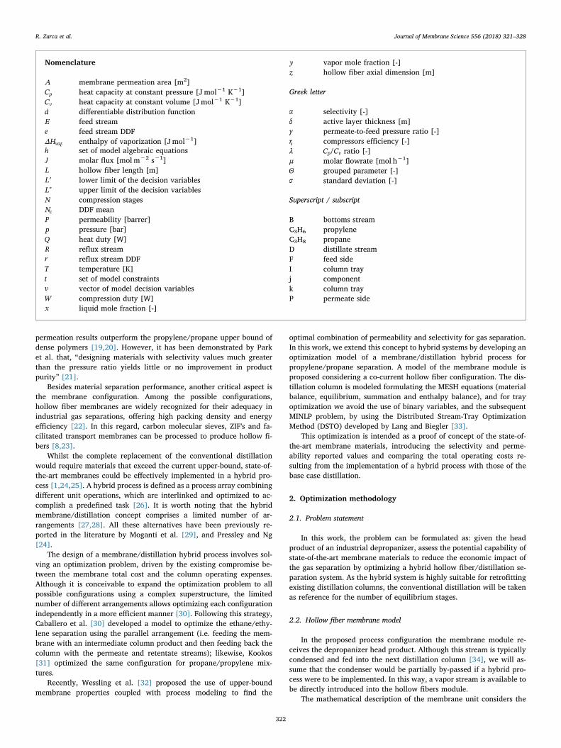
permeation results outperform the propylene/propane upper bound ofdense polymers [19,20]. However, it has been demonstrated by Parket al. that, “designing materials with selectivity values much greaterthan the pressure ratio yields little or no improvement in productpurity” [21].
Besides material separation performance, another critical aspect isthe membrane configuration. Among the possible configurations,hollow fiber membranes are widely recognized for their adequacy inindustrial gas separations, offering high packing density and energyefficiency [22]. In this regard, carbon molecular sieves, ZIF's and fa-cilitated transport membranes can be processed to produce hollow fi-bers [8,23].
Whilst the complete replacement of the conventional distillationwould require materials that exceed the current upper-bound, state-of-the-art membranes could be effectively implemented in a hybrid pro-cess [1,24,25]. A hybrid process is defined as a process array combiningdifferent unit operations, which are interlinked and optimized to ac-complish a predefined task [26]. It is worth noting that the hybridmembrane/distillation concept comprises a limited number of ar-rangements [27,28]. All these alternatives have been previously re-ported in the literature by Moganti et al. [29], and Pressley and Ng[24].
The design of a membrane/distillation hybrid process involves sol-ving an optimization problem, driven by the existing compromise be-tween the membrane total cost and the column operating expenses.Although it is conceivable to expand the optimization problem to allpossible configurations using a complex superstructure, the limitednumber of different arrangements allows optimizing each configurationindependently in a more efficient manner [30]. Following this strategy,Caballero et al. [30] developed a model to optimize the ethane/ethy-lene separation using the parallel arrangement (i.e. feeding the mem-brane with an intermediate column product and then feeding back thecolumn with the permeate and retentate streams); likewise, Kookos[31] optimized the same configuration for propane/propylene mix-tures.
Recently, Wessling et al. [32] proposed the use of upper-boundmembrane properties coupled with process modeling to find the
optimal combination of permeability and selectivity for gas separation.In this work, we extend this concept to hybrid systems by developing anoptimization model of a membrane/distillation hybrid process forpropylene/propane separation. A model of the membrane module isproposed considering a co-current hollow fiber configuration. The dis-tillation column is modeled formulating the MESH equations (materialbalance, equilibrium, summation and enthalpy balance), and for trayoptimization we avoid the use of binary variables, and the subsequentMINLP problem, by using the Distributed Stream-Tray OptimizationMethod (DSTO) developed by Lang and Biegler [33].
This optimization is intended as a proof of concept of the state-of-the-art membrane materials, introducing the selectivity and perme-ability reported values and comparing the total operating costs re-sulting from the implementation of a hybrid process with those of thebase case distillation.
2. Optimization methodology
2.1. Problem statement
In this work, the problem can be formulated as: given the headproduct of an industrial depropanizer, assess the potential capability ofstate-of-the-art membrane materials to reduce the economic impact ofthe gas separation by optimizing a hybrid hollow fiber/distillation se-paration system. As the hybrid system is highly suitable for retrofittingexisting distillation columns, the conventional distillation will be takenas reference for the number of equilibrium stages.
2.2. Hollow fiber membrane model
In the proposed process configuration the membrane module re-ceives the depropanizer head product. Although this stream is typicallycondensed and fed into the next distillation column [34], we will as-sume that the condenser would be partially by-passed if a hybrid pro-cess were to be implemented. In this way, a vapor stream is available tobe directly introduced into the hollow fibers module.
The mathematical description of the membrane unit considers the
Nomenclature
A membrane permeation area [m2]Cp heat capacity at constant pressure [J mol−1 K−1]Cv heat capacity at constant volume [Jmol−1 K−1]d differentiable distribution functionE feed streame feed stream DDFΔHvap enthalpy of vaporization [Jmol−1]h set of model algebraic equationsJ molar flux [mol m−2 s−1]L hollow fiber length [m]
′L lower limit of the decision variablesL" upper limit of the decision variablesN compression stagesNc DDF meanP permeability [barrer]p pressure [bar]Q heat duty [W]R reflux streamr reflux stream DDFT temperature [K]t set of model constraintsv vector of model decision variablesW compression duty [W]x liquid mole fraction [-]
y vapor mole fraction [-]z hollow fiber axial dimension [m]
Greek letter
α selectivity [-]δ active layer thickness [m]γ permeate-to-feed pressure ratio [-]η compressors efficiency [-]λ C C/p v ratio [-]μ molar flowrate [mol h−1]Θ grouped parameter [-]σ standard deviation [-]
Superscript / subscript
B bottoms streamC3H6 propyleneC3H8 propaneD distillate streamF feed sideI column trayj componentk column trayP permeate side
R. Zarca et al. Journal of Membrane Science 556 (2018) 321–328
322

following assumptions:
• The module operates isothermally and in the steady state.
• The feed stream is introduced in the shell side of the fibers, with thepermeate circulating in the lumen side.
• The feed and permeate streams flow in a co-current configuration.
• Plug-flow in both sides is assumed.
• The total pressure in the feed and permeate sides are kept constantas operating conditions.
• There is no pressure drop due to fluid dynamics, the only pressuregradient is the transmembrane pressure.
• The gas permeability is a material constant.
Fig. 1 shows a schematic diagram of the hollow fibers module. Themass balances for component j in the feed and permeate sides are asfollows:
= − ⋅dF z J z dA( ) ( )jF
j (1)
= ⋅dF z J z dA( ) ( )jP
j (2)
where Fj is the molar flowrate of component j, and dA is the fiber wallarea differential element. Given that the reported permeability can beconsidered as a normalized flux, we revert this conversion to calculatethe permeation flux through the active layer, as outlined by the solu-tion-diffusion theory [35]:
= ⋅⎡⎣⎢
− ⎤⎦⎥
J zΡδ
p z p z( ) ( ) ( )jj
jF
jP
(3)
where Ρj is the permeability of component j, δ is the thickness of theactive layer and pj
F and pjP are feed and permeate partial pressures of
component j, respectively. This should be interpreted as an approx-imation to homogenize the calculation method when evaluatingmembrane materials that perform a variety of transport mechanisms.The following dimensionless variables are defined:
= ∈z zL
z [0, 1] (4)
= ∈γpp
γ [0, 1]P
F (5)
==
∈F zF z
F zF( )
( )( 0)
[0, 1]jj
TF j
(6)
=∑
∈x zF z
F zx( )
( )( )
[0, 1]jjF
jF j
(7)
=∑
∈y zF z
F zy( )
( )( )
[0, 1]jjP
jP j
(8)
which stand for feed and permeate mole fraction, dimensionless axiallength, permeate-to-feed pressure ratio and dimensionless molar flow-rate, respectively; L is the fiber length. In addition, a grouped parameteris defined:
=⋅ ⋅⋅ =
ΘA Ρ pδ Fj
jF
T zF, 0 (9)
where A is the total membrane area. Rearranging terms, the massbalances can be rewritten as:
= − ⋅ −dFdz
Θ x γ y( )jF
j j j (10)
= ⋅ −dFdz
Θ x γ y( )jP
j j j (11)
==F 1jF
z 0 (12)
==F 0jP
z 0 (13)
These ordinary differential equations (ODEs) (Eqs. (10–13)) arediscretized using implicit Runge-Kutta collocation methods and solvedas algebraic equations.
2.3. Distillation model
For the distillation column, the model is taken from the work ofLang and Biegler [33]. A complete description of the mathematicaldevelopment can be found in the original manuscript, here we provide abrief overview. In order to avoid discrete decision variables, the modeluses differentiable distribution functions (DFF) for the feed streams,reflux stream and intermediate product streams (if present), in theform:
=⎡⎣
− ⎤⎦
∑ ⎡⎣
− ⎤⎦
∈
−
−
( )( )
d i k Iexp
exp,i
i Nσ
kk N
σ
2
2
c
c(14)
which corresponds to the discretization of a Gaussian distribution withmean Nc and standard deviation σ . Thus, using DDFs, the feed and re-flux streams can be distributed to all trays:
= ⋅E E ei i (15)
= ⋅R R ri i (16)
where Ei and Ri are the feed and reflux flowrates entering into the i-thtray, ei and ri are the corresponding differentiable distribution functionsand E and. are the total feed and reflux streams, respectively. Once thefeed and reflux streams are defined through a DDF, the model uses theconventional MESH equations (material balances, equilibrium, sum-mation and enthalpy balances) to formulate the distillation model. Asdescribed in [33] the model is also capable of calculating the number oftrays by relaxing the equilibrium equations in the MESH equations sothat the liquid phase disappears. This modification of the MESHequations allows dry trays to appear without pressure drop in the non-existing trays above the reflux insertion point. The optimization modelthen chooses the column operation with the optimal number of drytrays, which translates to the optimum number of trays required. Fig. 2depicts an overview of the modeling strategy.
The vapor-liquid equilibrium has been introduced using the K-valuecharts for C3 mixtures [36]. These charts are constructed upon experi-mental data, later displayed in nomograms. To allow its implementa-tion in computer calculations, a corresponding states type approach hasbeen reported in the bibliography [37]. This approach considers theequilibrium constant value as a function of pressure and temperatureexclusively, neglecting the effects of composition. This assumption isvalid for propane/propylene mixtures at the pressure and temperaturerange covered in this study.
Fig. 1. Schematic diagram of the hollow fibers module.
R. Zarca et al. Journal of Membrane Science 556 (2018) 321–328
323
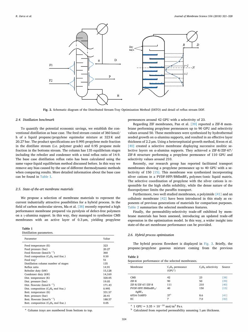
2.4. Distillation benchmark
To quantify the potential economic savings, we establish the con-ventional distillation as base case. The feed stream consist of 360 kmol/h of a liquid propane/propylene equimolar mixture at 323 K and20.27 bar. The product specifications are 0.995 propylene mole fractionin the distillate stream (i.e. polymer grade) and 0.95 propane molefraction in the bottoms stream. The column has 135 equilibrium stagesincluding the reboiler and condenser with a total reflux ratio of 14.9.The base case distillation reflux ratio has been calculated using thesame vapor-liquid equilibrium method discussed before. In this way weremove any bias caused by the use of different thermodynamic methodswhen comparing results. More detailed information about the base casecan be found in Table 1.
2.5. State-of-the-art membrane materials
We propose a selection of membrane materials to represent thecurrent industrially attractive possibilities for a hybrid process. In thefield of carbon molecular sieves, Ma et al. [38] recently reported a highperformance membrane prepared via pyrolysis of defect-free polymerson a γ-alumina support. In this way, they managed to synthesize CMSmembranes with an active layer of 0.3 µm, yielding propylene
permeances around 42 GPU with a selectivity of 23.Regarding ZIF membranes, Pan et al. [39] reported a ZIF-8 mem-
brane performing propylene permeances up to 90 GPU and selectivityvalues around 50. These membranes were synthesized by hydrothermalseeded growth on α-alumina supports, and resulted in an effective layerthickness of 2.2 µm. Using a heteroepitaxial growth method, Kwon et al.[40] created a selective membrane displaying successive zeolitic se-lective layers on α-alumina supports. They achieved a ZIF-8/ZIF-67/ZIF-8 structure performing a propylene permeance of 110 GPU andselectivity values around 210.
Recently, our research group has reported facilitated transportmembranes showing a propylene permeance up to 40 GPU with a se-lectivity of 150 [15]. This membrane was synthesized incorporatingsilver cations in a PVDF-HFP/BMImBF4 polymer/ionic liquid matrix.The selective coordination of propylene with the silver cations is re-sponsible for the high olefin solubility, while the dense nature of thefluoropolymer limits the paraffin transport.
Furthermore, two well studied membranes, a polyimide [41] and ancellulosic membrane [42] have been introduced in this study as ex-ponents of previous generations of materials for comparison purposes.Table 2 summarizes the selected membranes features.
Finally, the permeability-selectivity trade-off exhibited by mem-brane materials has been assessed, introducing an updated trade-offexpression in the optimization model. In this way, a wider insight intostate-of-the-art membrane performance can be provided.
2.6. Hybrid process optimization
The hybrid process flowsheet is displayed in Fig. 3. Briefly, thepropane/propylene gaseous mixture coming from the previous
Fig. 2. Schematic diagram of the Distributed Stream-Tray Optimization Method (DSTO) and detail of reflux stream DDF.
Table 1Distillation parameters.
Parameter Value
Feed temperature (K) 323Feed pressure (bar) 20.27Feed flowrate (kmol h−1) 360Feed composition (C3H6 mol frac.) 0.50Feed traya 51Distillation column number of stages 135Reflux ratio 14.91Reboiler duty (kW) 15,128Condenser duty (kW) 14,169Dist. temperature (K) 320.05Dist. pressure (bar) 19.05Dist. flowrate (kmol h−1) 171.43Dist. composition (C3H6 mol frac.) 0.995Bott. temperature (K) 331.57Bott. pressure (bar) 20.41Bott. flowrate (kmol h−1) 188.57Bott. composition (C3H6 mol frac.) 0.05
a Column trays are numbered from bottom to top.
Table 2Separation performance of the selected membranes.
Membrane C3H6 permeance(GPUa)
C3H6 selectivity Source
CMS 42 23 [38]ZIF-8 90 50 [39]ZIF-8/ZIF-67/ZIF-8 111 210 [40]PVDF-HFP/BMImBF4/
AgBF440 150 [15]
6FDA-TeMPD 37b 8.6 [41]EC 7 7.0 [42]
a 1 GPU=3.35× 10⁻¹⁰ mol/m2 Pa s.b Calculated from reported permeability assuming 1 µm thickness.
R. Zarca et al. Journal of Membrane Science 556 (2018) 321–328
324
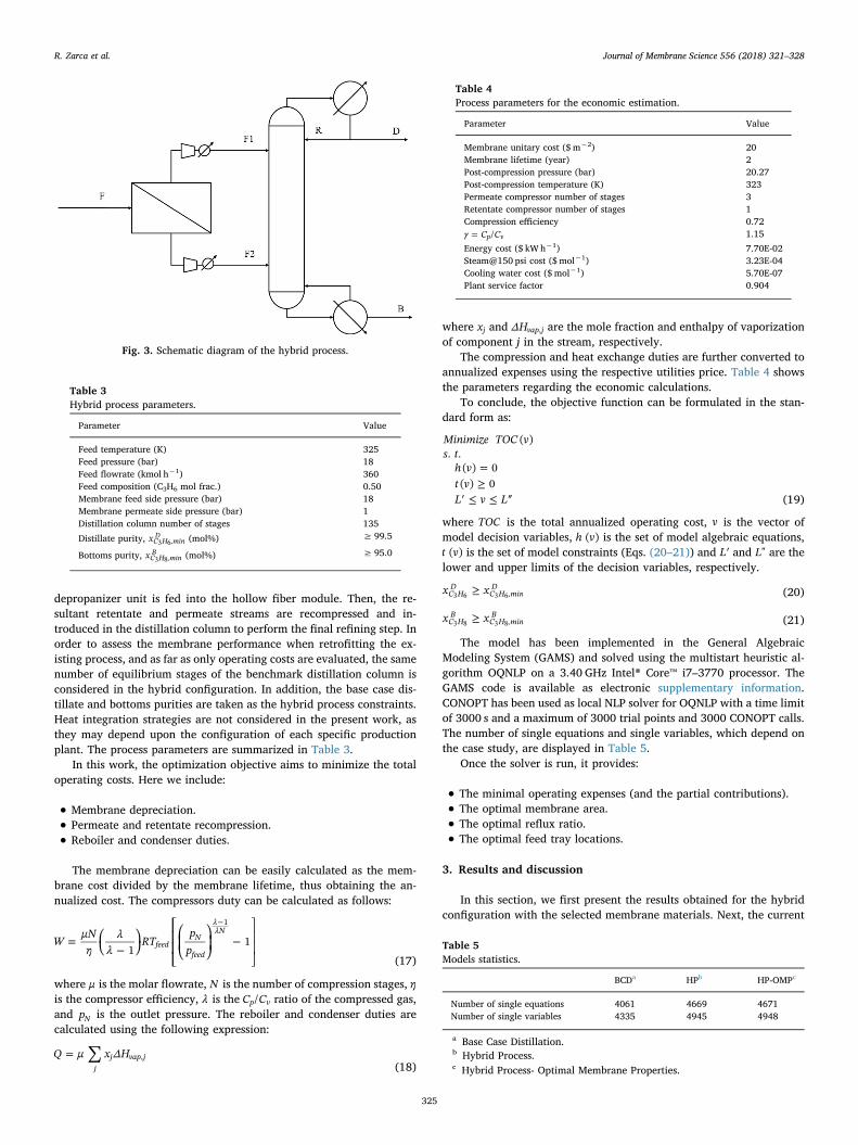
depropanizer unit is fed into the hollow fiber module. Then, the re-sultant retentate and permeate streams are recompressed and in-troduced in the distillation column to perform the final refining step. Inorder to assess the membrane performance when retrofitting the ex-isting process, and as far as only operating costs are evaluated, the samenumber of equilibrium stages of the benchmark distillation column isconsidered in the hybrid configuration. In addition, the base case dis-tillate and bottoms purities are taken as the hybrid process constraints.Heat integration strategies are not considered in the present work, asthey may depend upon the configuration of each specific productionplant. The process parameters are summarized in Table 3.
In this work, the optimization objective aims to minimize the totaloperating costs. Here we include:
• Membrane depreciation.
• Permeate and retentate recompression.
• Reboiler and condenser duties.
The membrane depreciation can be easily calculated as the mem-brane cost divided by the membrane lifetime, thus obtaining the an-nualized cost. The compressors duty can be calculated as follows:
= ⎛⎝ −
⎞⎠
⎡
⎣
⎢⎢
⎛
⎝⎜
⎞
⎠⎟ −
⎤
⎦
⎥⎥
−
WμNη
λλ
RTp
p11feed
N
feed
λλN
1
(17)
where μ is the molar flowrate, N is the number of compression stages, ηis the compressor efficiency, λ is the C C/p v ratio of the compressed gas,and pN is the outlet pressure. The reboiler and condenser duties arecalculated using the following expression:
∑=Q μ x ΔHj
j vap j,(18)
where xj and ΔHvap j, are the mole fraction and enthalpy of vaporizationof component j in the stream, respectively.
The compression and heat exchange duties are further converted toannualized expenses using the respective utilities price. Table 4 showsthe parameters regarding the economic calculations.
To conclude, the objective function can be formulated in the stan-dard form as:
=≥
′ ≤ ≤ ″
Minimize TOC vs t
h vt vL v L
( ). .
( ) 0( ) 0
(19)
where TOC is the total annualized operating cost, v is the vector ofmodel decision variables, h v( ) is the set of model algebraic equations,t v( ) is the set of model constraints (Eqs. (20–21)) and ′L and L" are thelower and upper limits of the decision variables, respectively.
≥x xC HD
C H minD
,3 6 3 6 (20)
≥x xC HB
C H minB
,3 8 3 8 (21)
The model has been implemented in the General AlgebraicModeling System (GAMS) and solved using the multistart heuristic al-gorithm OQNLP on a 3.40 GHz Intel® Core™ i7–3770 processor. TheGAMS code is available as electronic supplementary information.CONOPT has been used as local NLP solver for OQNLP with a time limitof 3000 s and a maximum of 3000 trial points and 3000 CONOPT calls.The number of single equations and single variables, which depend onthe case study, are displayed in Table 5.
Once the solver is run, it provides:
• The minimal operating expenses (and the partial contributions).
• The optimal membrane area.
• The optimal reflux ratio.
• The optimal feed tray locations.
3. Results and discussion
In this section, we first present the results obtained for the hybridconfiguration with the selected membrane materials. Next, the current
Fig. 3. Schematic diagram of the hybrid process.
Table 3Hybrid process parameters.
Parameter Value
Feed temperature (K) 325Feed pressure (bar) 18Feed flowrate (kmol h−1) 360Feed composition (C3H6 mol frac.) 0.50Membrane feed side pressure (bar) 18Membrane permeate side pressure (bar) 1Distillation column number of stages 135
Distillate purity, xC H minD3 6, (mol%) ≥ 99.5
Bottoms purity, xC H minB3 8, (mol%) ≥ 95.0
Table 4Process parameters for the economic estimation.
Parameter Value
Membrane unitary cost ($ m−2) 20Membrane lifetime (year) 2Post-compression pressure (bar) 20.27Post-compression temperature (K) 323Permeate compressor number of stages 3Retentate compressor number of stages 1Compression efficiency 0.72
=γ C C/p v 1.15
Energy cost ($ kW h−1) 7.70E-02Steam@150 psi cost ($ mol−1) 3.23E-04Cooling water cost ($ mol−1) 5.70E-07Plant service factor 0.904
Table 5Models statistics.
BCDa HPb HP-OMPc
Number of single equations 4061 4669 4671Number of single variables 4335 4945 4948
a Base Case Distillation.b Hybrid Process.c Hybrid Process- Optimal Membrane Properties.
R. Zarca et al. Journal of Membrane Science 556 (2018) 321–328
325

membrane upper bound is introduced in the model to study the desir-able permeability/selectivity combination of a hypothetically optimalmembrane material. Additionally, the impact of the membrane cost onthe economic evaluation is assessed.
3.1. State-of-the-art membranes optimization results
Table 6 displays the resultant membrane area, reflux ratio and po-tential savings derived from the implementation of each membrane in ahybrid configuration. The highly permeable and highly selective ZIFs,CMS and facilitated transport membranes (A-D) can potentially reducethe operating expenses by around 30–55%. In addition, advancedpolyimides, as 6FDA-TeMPD (E), which provide high permeance butmoderate selectivity, are still capable of reducing the total operatingcosts by 18%. Finally, the cellulosic membrane (F), due to its lowpermeance and selectivity, achieves a TOC reduction of around 10%.
The TOC reduction due to the implementation of a hollow fibermodule in series is clearly related to the decrease in the required refluxratio for a given product quality. Although the reboiler and condenserduties are very similar, the use of steam requires that more than 95% ofthe base case operating costs are generated by the reboiler. Fig. 4 un-folds the total operating expenses for each case. As expected, themembrane module helps reduce the required reflux ratio, decreasingthe steam supply to the reboiler and its associated cost. It is worthnoting that, despite this reduction, the reboiler operating cost is still thelargest contribution to the total operating costs, while the condenserand retentate compressor operating costs are almost negligible.
Focusing on the intermediate streams (F1 and F2 in Fig. 3), it isnoticeable how the optimal solution comprises, in all cases, approxi-mately the same flowrates, and the total savings are eventually de-termined by the purity achieved in these streams as can be seen inTable 7. In this regard, the optimal membrane area for case B is higherthan that of case D. Though both have the same propylene permeance,
the first is far more selective. Here, the extra cost is offset by the purityreached in the permeate stream. Comparing membranes with similarselectivity (E and F), we observe the strong dependence of the optimalrequired area on the membrane permeance.
Since the hybrid configuration may become uncompetitive com-pared to the conventional distillation depending on the membraneunitary cost, it is advisable to perform a sensitivity analysis of the op-timum solutions. Fig. 5 displays the TOC variation for each membranewith increasing membrane prices up to 200 $/m2. In all cases, with theexception of the cellulosic membrane, the optimal configuration doesnot vary significantly, and the resultant TOC increase is proportional tothe optimal membrane area. On the other hand, the cellulosic mem-brane hybrid configuration, due to the large area required, is not sui-table for replacing the base case distillation when the membrane costexceeds ~100 $/m2, and consequently, the membrane module has beenremoved during the optimization run.
This analysis reveals a remarkable range of suitability for medium tohigh performance membrane materials when implemented in a hybridconfiguration, regarding the membrane production cost.
3.2. Upper-bound role in the hybrid configuration
An interesting point when dealing with membranes is the trade-offexisting between selectivity and gas permeability, which is limited bythe upper-bound in the Robeson plot. By introducing the Robeson plotupper-bound expression in the optimization model we can explore theoptimal permeability and selectivity values of a hypothetically optimalmembrane material, given the membranes state-of-the art [30,31].Fig. 6 represents an updated Robeson plot for propane/propylenemixtures.
The corresponding mathematical expression is:
= −α P97.51C H C H C H/0.362
3 6 3 8 3 6 (22)
This updated upper-bound is slightly displaced towards the high-performance region compared to the previous version reported byBurns and Koros [19], as a result of the continuous research in mem-brane materials over the recent years. In this section we will evaluatethe membrane productivity in terms of permeability instead of per-meance, due to the nature of the Robeson plot, which is intended tocompare materials and not specific membrane morphologies.
Once the upper-bound is introduced in the optimization problem, inaddition to membrane area, reflux ratio and stream locations, theprogram also provides the optimal balance between permeability andselectivity. An active layer thickness of 1 µm has been assumed, as thisis a typical value in the hollow fiber manufacture. The same hybridprocess parameters considered in the previous discussion have beenused for this section (see Table 3). The results obtained in this sectionare summarized in Table 8.
The optimal solution involves, in this case, very similar intermediateflowrates to those discussed in the previous section (see Table 7), andthe potential reflux reduction is again determined by the purity oftheses streams (F1 and F2 in Fig. 3). It is worth noting the strong in-fluence of the membrane cost on the optimal permeability/selectivitytrade-off. As the membrane cost weight on the objective function
Table 6Optimization results.
ID Membrane C3H6 permeance (GPU) Selectivity Area (×103 m2) Reflux TOC (MM$/y) Savings (%)
– None – – – 14.9 4.05 0.0A ZIF8 / ZIF67/ZIF8 111 209 2.8 4.5 1.78 56.2B PVDF-HFP/AgBF4/BMImBF4 40 150 7.4 5.3 2.02 50.3C ZIF 8 91 50 2.9 7.4 2.50 38.3D 6FDA-based polyimide CMS 42 23 5.8 8.7 2.87 29.2E 6FDA-TeMPD 37 8.9 5.3 10.5 3.34 17.6F EC 6 7.0 23.2 11.2 3.65 9.9
Fig. 4. Disaggregated operating costs for each case. A-F defined in Table 6.
R. Zarca et al. Journal of Membrane Science 556 (2018) 321–328
326

increases, the membrane tends to increase the permeability at the ex-pense of selectivity. In the most unfavorable case (i.e. 200 $/m2) themembrane is highly permeable and the selectivity falls to a value closerto the pressure ratio, which allows a prominent decrease in the requiredarea while still maintaining an adequate permeate purity. These resultsare in good agreement with Huang et al. [43] findings on the pressureratio-selectivity relation: “High permeance membranes are alwaysgood, but the optimum membrane selectivity depends on the processand the operating conditions, particularly the pressure ratio”. In-creasing the membrane selectivity far beyond the industrially suitablepressure ratio produces minor increments in the product purity at theexpense of larger membrane areas, as the process enters in the pressure
ratio-limited region.Comparing with the real membranes selected for this study, the
carbon molecular sieve (membrane D) would be the option of choice,given the conservative upper-bound considered in Eq. (22), which isbelow the performance of membranes A, B and C. This gives an idea ofthe state-of-the-art membrane materials performance for process in-tensification when implemented in a hybrid configuration.
4. Conclusions
Membrane technology offers remarkable opportunities to intensifythe olefin/paraffin separation process when implemented in hybridsystems along with the conventional distillation. In this work, the op-timization of a membrane/distillation hybrid process with state-of-the-art membranes yielded total operating cost savings of 10–50% com-pared with the distillation benchmark.
The evaluation of the Robeson plot upper-bound reveals the im-portance of the operating conditions when it comes to select the mostsuitable membrane. Especially, the pressure ratio may limit the ad-vantages of highly selective membranes. In this regard, membrane re-searchers should consider the particularities of each specific applicationin order to tailor the membrane properties accordingly.
Acknowledgements
Financial support from the Spanish Ministry of Science under theprojects CTQ2015–66078-R and CTQ2016–75158-R (MINECO, Spain-FEDER 2014–2020) is gratefully acknowledged. Raúl Zarca also thanksthe Universidad de Cantabria for a postgraduate fellowship.
Appendix A. Supplementary material
Supplementary data associated with this article can be found in theonline version at http://dx.doi.org/10.1016/j.memsci.2018.04.016.
Table 7Intermediate streams results.
ID Membrane F1 flowrate (kmol/h) F2 flowrate (kmol/h) F1C3H6 purity (kmol/h) F2C3H6 purity (kmol/h) F1 feed traya F2 feed traya Savings (%)
A ZIF8 / ZIF67/ZIF8 159 201 0.985 0.115 108 19 56.2B PVDF-HFP/AgBF4/
BMImBF4157 203 0.981 0.127 102 19 50.3
C ZIF 8 158 202 0.950 0.149 83 18 38.3D 6FDA-based polyimide CMS 161 199 0.906 0.170 75 19 29.2E 6FDA-TeMPD 167 193 0.815 0.227 70 24 17.6F EC 147 213 0.806 0.289 74 30 9.9
a Column trays are numbered from bottom to top.
Fig. 5. Effect of the membrane cost on optimal TOC for the studied membranes.
Fig. 6. Robeson plot for propane/propylene separation membranes displayingthe upper-bound.
Table 8Upper-bound optimization results.
Membrane cost ($/m2)
20 100 200
Propylene permeability (barrera) 16 74 134Propylene selectivity 36 21 17Membrane area (×103 m2) 15.0 3.1 1.6F1 flowrate (kmol/h) 155 158 157F2 flowrate (kmol/h) 205 202 203F1C3H6 purity 0.937 0.901 0.885F2C3H6 purity 0.171 0.187 0.203F1 feed trayb 82 76 76F2 feed trayb 21 21 23Reflux ratio 8.0 8.9 9.3TOC (MM$/y) 2.77 3.02 3.13Savings (%) 31.5 25.5 22.8
a 1 barrer= 3.348× 10⁻¹⁶ mol m/m2 Pa s.b Column trays are numbered from bottom to top.
R. Zarca et al. Journal of Membrane Science 556 (2018) 321–328
327

References
[1] D.S. Sholl, R.P. Lively, Seven chemical separations to change the world, Nature 532(2016) 435–437.
[2] Kumar, R., Prausnitz, J.M., King, C.J., 1972. Process design considerations for ex-tractive distillation: separation of propylene-propane. In: Dimitrios P. Tassios (ed.),Extractive and Azeotropic Distillation. pp. 16–34.
[3] C.M. Shu, S. Kulvaranon, M.E. Findley, A.I. Liapis, Experimental and computationalstudies on propane-propylene separation by adsorption and variable-temperaturestepwise desorption, Sep. Technol. 1 (1990) 18–28.
[4] J. Padin, S.U. Rege, R.T. Yang, L.S. Cheng, Molecular sieve sorbents for kineticseparation of propane/propylene, Chem. Eng. Sci. 55 (2000) 4525–4535.
[5] J.C. Charpentier, In the frame of globalization and sustainability, process in-tensification, a path to the future of chemical and process engineering (moleculesinto money), Chem. Eng. J. 134 (2007) 84–92.
[6] R.W. Baker, Future directions of membrane gas separation technology, Ind. Eng.Chem. Res. 41 (2002) 1393–1411.
[7] R. Faiz, K. Li, Polymeric membranes for light olefin/paraffin separation,Desalination 287 (2012) 82–97.
[8] L. Xu, et al., Olefins-selective asymmetric carbon molecular sieve hollow fibermembranes for hybrid membrane-distillation processes for olefin/paraffin separa-tions, J. Membr. Sci. 423–424 (2012) 314–323.
[9] M. Askari, T.-S. Chung, Natural gas purification and olefin/paraffin separationusing thermal cross-linkable co-polyimide/ZIF-8 mixed matrix membranes, J.Membr. Sci. 444 (2013) 173–183.
[10] J. Liu, et al., A new carbon molecular sieve for propylene/propane separations,Carbon 85 (2015) 201–211.
[11] K. Li, et al., Zeolitic imidazolate frameworks for kinetic separation of propane andpropene, J. Am. Chem. Soc. 131 (2009) 10368–10369.
[12] B. Demir, M.G. Ahunbay, Propane/propylene separation in ion-exchanged zeolite-like metal organic frameworks, Microporous Mesoporous Mater. 198 (2014)185–193.
[13] H.T. Kwon, H.K. Jeong, Improving propylene/propane separation performance ofZeolitic-imidazolate framework ZIF-8 membranes, Chem. Eng. Sci. 124 (2015)20–26.
[14] M. Fallanza, A. Ortiz, D. Gorri, I. Ortiz, Polymer-ionic liquid composite membranesfor propane/propylene separation by facilitated transport, J. Membr. Sci. 444(2013) 164–172.
[15] R. Zarca, A. Ortiz, D. Gorri, I. Ortiz, Generalized predictive modeling for facilitatedtransport membranes accounting for fixed and mobile carriers, J. Membr. Sci. 542(2017) 168–176.
[16] M.T. Ravanchi, T. Kaghazchi, A. Kargari, Supported liquid membrane separation ofpropylene-propane mixtures using a metal ion carrier, Desalination 250 (2010)130–135.
[17] S.W. Kang, et al., Effect of the polarity of silver nanoparticles induced by ionicliquids on facilitated transport for the separation of propylene/propane mixtures, J.Membr. Sci. 322 (2008) 281–285.
[18] S. Jeong, S.W. Kang, Effect of Ag2O nanoparticles on long-term stable polymer/AgBF4/Al(NO3)3complex membranes for olefin/paraffin separation, Chem. Eng. J.327 (2017) 500–504.
[19] R.L. Burns, W.J. Koros, Defining the challenges for C3H6/C3H8 separation usingpolymeric membranes, J. Membr. Sci. 211 (2003) 299–309.
[20] L.M. Robeson, The upper bound revisited, J. Membr. Sci. 320 (2008) 390–400.[21] H.B. Park, J. Kamcev, L.M. Robeson, M. Elimelech, B.D. Freeman, Maximizing the
right stuff: the trade-off between membrane permeability and selectivity, Science356 (2017) 1138–1148.
[22] D.C. Nymeijer, T. Visser, R. Assen, M. Wessling, Composite hollow fiber gas-liquidmembrane contactors for olefin/paraffin separation, Sep. Purif. Technol. 37 (2004)209–220.
[23] A.J. Brown, et al., Interfacial microfluidic processing of metal-organic frameworkhollow fiber membranes, Science 345 (2014) 72–75.
[24] T.G. Pressly, K.M. Ng, A break-even analysis of distillation-membrane hybrids,AIChE J. 44 (1998) 93–105.
[25] A. Norkobilov, D. Gorri, I. Ortiz, Comparative study of conventional, reactive-dis-tillation and pervaporation integrated hybrid process for ethyl tert-butyl etherproduction, Chem. Eng. Process. Process Intensif. 122 (2017) 434–446.
[26] F. Lipnizki, R.W. Field, P.-K. Ten, Pervaporation-based hybrid process: a review ofprocess design, applications and economics, J. Membr. Sci. 153 (1999) 183–210.
[27] W. Stephan, R.D. Noble, C.A. Koval, Design methodology for a membrane/dis-tillation column hybrid process, J. Membr. Sci. 99 (1995) 259–272.
[28] T. Pettersen, A. Argo, R.D. Noble, C.A. Koval, Design of combined membrane anddistillation processes, Sep. Technol. 6 (1996) 175–187.
[29] S. Moganti, R.D. Noble, C.A. Koval, Analysis of a membrane/distillation columnhydrid process, J. Membr. Sci. 93 (1994) 31–44.
[30] J.A. Caballero, et al., Design of hybrid distillation - vapor membrane separationsystems, Ind. Eng. Chem. Res. 48 (2009) 9151–9162.
[31] I.K. Kookos, Optimal design of membrane/distillation column hybrid processes, Ind.Eng. Chem. Res. 42 (2003) 1731–1738.
[32] B. Ohs, J. Lohaus, M. Wessling, Optimization of membrane based nitrogen removalfrom natural gas, J. Membr. Sci. 498 (2016) 291–301.
[33] Y.D. Lang, L.T. Biegler, Distributed stream method for tray optimization, AIChE J.48 (2002) 582–595.
[34] W.L. Luyben, Dynamic simulation of flooded condensers, Chem. Eng. Res. Des. 118(2017) 12–20.
[35] J.G. Wijmans, R.W. Baker, The solution-diffusion model: a review, J. Membr. Sci.107 (1995) 1–21.
[36] E.G. Scheibel, F.J. Jenny, Nomographs for enthalpies of pure hydrocarbons andtheir mixtures, Ind. Eng. Chem. 37 (1945) 990–995.
[37] Dimitrios Tassios, Applied Chemical Engineering Thermodynamics, Springer,Berlin, 1993.
[38] X. Ma, Y.S. Lin, X. Wei, J. Kniep, Ultrathin carbon molecular sieve membrane forpropylene/propane separation, AIChE J. 62 (2016) 491–499.
[39] Y. Pan, T. Li, G. Lestari, Z. Lai, Effective separation of propylene/propane binarymixtures by ZIF-8membranes, J. Membr. Sci. 390–391 (2012) 93–98.
[40] H.T. Kwon, H.K. Jeong, A.S. Lee, H.S. An, J.S. Lee, Heteroepitaxially grown zeoliticimidazolate framework membranes with unprecedented propylene/propane se-paration performances, J. Am. Chem. Soc. 137 (2015) 12304–12311.
[41] K. Okamoto, K. Noborio, J. Hao, K. Tanaka, H. Kita, Permeation and separationproperties of polyimide membranes to 1,3-butadiene and n-butane, J. Membr. Sci.134 (1997) 171–179.
[42] A. Ito, S.-T. Hwang, Permeation of propane and propylene through cellulosicpolymer membranes, J. Appl. Polym. Sci. 38 (1989) 483–490.
[43] Y. Huang, T.C. Merkel, R.W. Baker, Pressure ratio and its impact on membrane gasseparation processes, J. Membr. Sci. 463 (2014) 33–40.
R. Zarca et al. Journal of Membrane Science 556 (2018) 321–328
328

Appendices
Appendices
132
A.1 List of additional scientific publications Scientific articles published in non-JCR indexed journals R. Zarca, A. Ortiz, D. Gorri, I. Ortiz, Facilitated transport of propylene through composite polymer-ionic liquid membranes. Mass transfer analysis, Chem. Prod. Process. Model. 11 (2016) 77–81. (CiteScore 2017: 0.96). Scientific articles submitted to JCR indexed journals R. Zarca, A. Ortiz, D. Gorri, L.T. Biegler, I. Ortiz, Optimization of multistage olefin/paraffin separation membrane processes through rigorous modeling, AIChE J. Under review. R. Zarca, A.C.C. Campos, A. Ortiz, D. Gorri, I. Ortiz, Comprehensive study on PVDF-HFP/BMImBF4/AgBF4 membranes for propylene purification, J. Memb. Sci. Under review.

Raúl Zarca, Alfredo Ortiz*, Daniel Gorri and Inmaculada Ortiz
Facilitated Transport of Propylene ThroughComposite Polymer-Ionic Liquid Membranes.Mass Transfer Analysis
DOI 10.1515/cppm-2015-0072Received December 22, 2015; accepted December 22, 2015
Abstract: Separation of light gaseous olefins from paraffin’sof the refinery process off-gasses has been traditionallyperformed by cryogenic distillation, which is a highly capi-tal and energy intensive operation. This handicap createsan incentive for the investigation of alternative olefin/par-affin separation technologies. In this regard, membranetechnology supposes a potential solution for process inten-sification. Previous works of our research group reportedthe use of facilitated transport composite membranes inte-grating the use of PVDF-HFPpolymer, BMImBF4 ionic liquidand AgBF4 silver salt. In this type of membranes, the silvercations react selectively and reversibly with the olefin,allowing the separation via mobile and fixed carriermechanisms. Ionic liquidswere selected asmembrane addi-tives because in addition to their negligible vapor pressurethat avoids solvent losses by evaporation, they providestability to the metallic cation dissolved inside, and modifythe structure improving the facilitated transport. This tech-nology offers a commercial attractive separation alternativethanks to their modular form of operation, high values ofselectivity and permeability and low operational costs. Inthe present work, propane/propylene permeation experi-ments involving the use ionic liquids and different mem-brane compositions were performed. Moreover, basing onthe transport and equilibrium parameters previouslyobtained, a mathematical model description of the systemwill be proposed fitting the remaining parameters andallowing the design and optimization of the propane/pro-pylene separation process at industrial levels.
Keywords: facilitated transport, propylene, ionic liquids,silver, membrane composite
1 Introduction
Light olefins such as ethylene and propylene are impor-tant petrochemical building blocks which are further pro-cessed to yield a wide range of final products such ascosmetics, textile products, paints, tools or plastics forinstance. Light olefins are usually obtained, as a mixturewith paraffins, by steam cracking processes, fluidizedcatalytic cracking or alkane dehydrogenation.
The separation of these streams is a key issuebecause it is one of the most difficult and also the mostcostly separation process in the petrochemical industry.Traditional separation processes like low-temperaturedistillation, require voluminous equipment operating athigh pressures or low temperatures and very large refluxratios due to the very small difference in the relativevolatilities between olefins and their corresponding par-affins [1]. In recognition of these costs alternative energy-saving separation processes are required.
In this sense, membrane technology presents a greatpotential for energy and capital saving and therefore theuse of membranes has been the focal point of research ofmany authors. Criteria for selecting the most suitablemembrane for a given application are complex; nonethe-less, durability, mechanical and thermal stability at theoperating conditions, productivity and separation effi-ciency and costs are important stipulations that must beconsidered [2]. Among these requirements selectivity andpermeation rate are clearly the most basic, while therelative importance of the rest of them varies with theapplication. Therefore a wide variety of different mem-brane alternatives can be considered [3]. The use of poly-meric, inorganic and supported liquid membranes forolefin/ paraffin separation has been studied rather exten-sively, however these membranes may suffer severe plas-ticization effect, low stability, poor mechanical resistanceand expensive and complex preparation methods andtherefore their performance has not met the requirementsfor commercial applications [4, 5].
Recently our research group proposed the use ofnovel polymer-ionic liquid-Ag+ composite as facilitatedtransport membranes to carry out the separation of
*Corresponding author: Alfredo Ortiz, Department of Chemical &Biomolecular Engineering, University of Cantabria, Av. Los Castross/n., 39005 Santander, Spain, E-mail: [email protected]úl Zarca, Daniel Gorri, Inmaculada Ortiz, Department of Chemical& Biomolecular Engineering, University of Cantabria, Av. Los Castross/n., 39005 Santander, Spain
Chem. Prod. Process Model. 2016; aop
Brought to you by | New York University Bobst Library Technical ServicesAuthenticated
Download Date | 2/5/16 10:43 AM
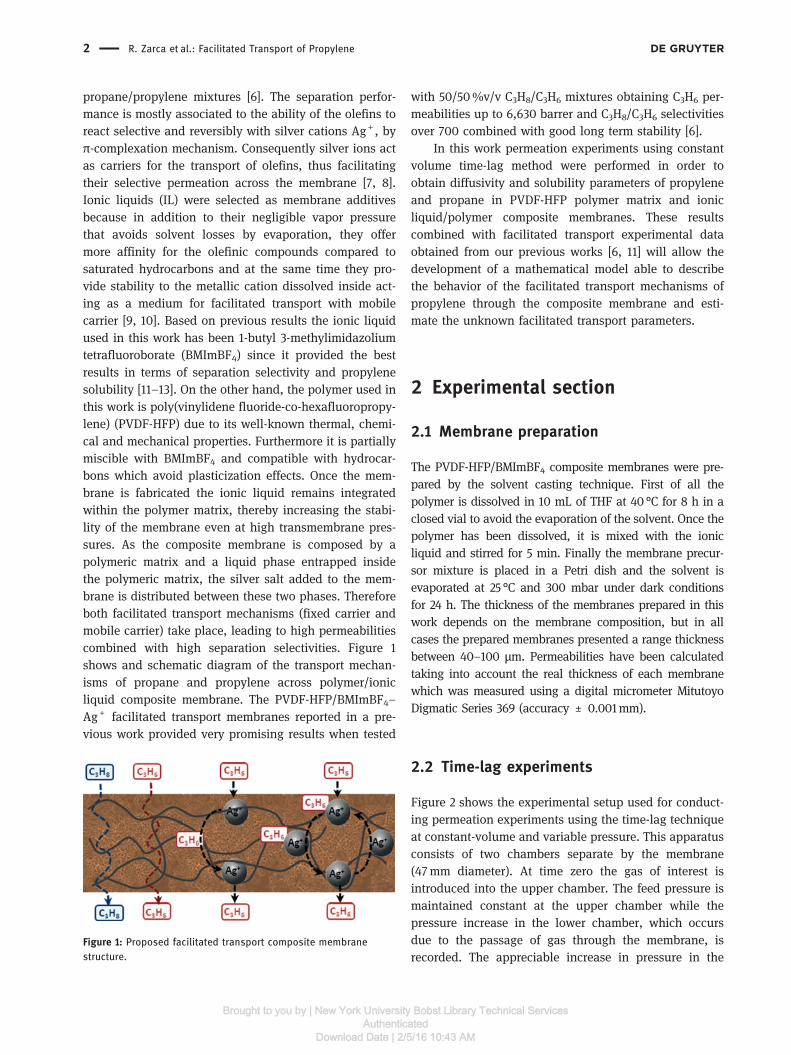
propane/propylene mixtures [6]. The separation perfor-mance is mostly associated to the ability of the olefins toreact selective and reversibly with silver cations Ag+ , byπ-complexation mechanism. Consequently silver ions actas carriers for the transport of olefins, thus facilitatingtheir selective permeation across the membrane [7, 8].Ionic liquids (IL) were selected as membrane additivesbecause in addition to their negligible vapor pressurethat avoids solvent losses by evaporation, they offermore affinity for the olefinic compounds compared tosaturated hydrocarbons and at the same time they pro-vide stability to the metallic cation dissolved inside act-ing as a medium for facilitated transport with mobilecarrier [9, 10]. Based on previous results the ionic liquidused in this work has been 1-butyl 3-methylimidazoliumtetrafluoroborate (BMImBF4) since it provided the bestresults in terms of separation selectivity and propylenesolubility [11–13]. On the other hand, the polymer used inthis work is poly(vinylidene fluoride-co-hexafluoropropy-lene) (PVDF-HFP) due to its well-known thermal, chemi-cal and mechanical properties. Furthermore it is partiallymiscible with BMImBF4 and compatible with hydrocar-bons which avoid plasticization effects. Once the mem-brane is fabricated the ionic liquid remains integratedwithin the polymer matrix, thereby increasing the stabi-lity of the membrane even at high transmembrane pres-sures. As the composite membrane is composed by apolymeric matrix and a liquid phase entrapped insidethe polymeric matrix, the silver salt added to the mem-brane is distributed between these two phases. Thereforeboth facilitated transport mechanisms (fixed carrier andmobile carrier) take place, leading to high permeabilitiescombined with high separation selectivities. Figure 1shows and schematic diagram of the transport mechan-isms of propane and propylene across polymer/ionicliquid composite membrane. The PVDF-HFP/BMImBF4–Ag+ facilitated transport membranes reported in a pre-vious work provided very promising results when tested
with 50/50%v/v C3H8/C3H6 mixtures obtaining C3H6 per-meabilities up to 6,630 barrer and C3H8/C3H6 selectivitiesover 700 combined with good long term stability [6].
In this work permeation experiments using constantvolume time-lag method were performed in order toobtain diffusivity and solubility parameters of propyleneand propane in PVDF-HFP polymer matrix and ionicliquid/polymer composite membranes. These resultscombined with facilitated transport experimental dataobtained from our previous works [6, 11] will allow thedevelopment of a mathematical model able to describethe behavior of the facilitated transport mechanisms ofpropylene through the composite membrane and esti-mate the unknown facilitated transport parameters.
2 Experimental section
2.1 Membrane preparation
The PVDF-HFP/BMImBF4 composite membranes were pre-pared by the solvent casting technique. First of all thepolymer is dissolved in 10 mL of THF at 40 °C for 8 h in aclosed vial to avoid the evaporation of the solvent. Once thepolymer has been dissolved, it is mixed with the ionicliquid and stirred for 5 min. Finally the membrane precur-sor mixture is placed in a Petri dish and the solvent isevaporated at 25 °C and 300 mbar under dark conditionsfor 24 h. The thickness of the membranes prepared in thiswork depends on the membrane composition, but in allcases the prepared membranes presented a range thicknessbetween 40–100 μm. Permeabilities have been calculatedtaking into account the real thickness of each membranewhich was measured using a digital micrometer MitutoyoDigmatic Series 369 (accuracy ± 0.001mm).
2.2 Time-lag experiments
Figure 2 shows the experimental setup used for conduct-ing permeation experiments using the time-lag techniqueat constant-volume and variable pressure. This apparatusconsists of two chambers separate by the membrane(47mm diameter). At time zero the gas of interest isintroduced into the upper chamber. The feed pressure ismaintained constant at the upper chamber while thepressure increase in the lower chamber, which occursdue to the passage of gas through the membrane, isrecorded. The appreciable increase in pressure in the
Figure 1: Proposed facilitated transport composite membranestructure.
2 R. Zarca et al.: Facilitated Transport of Propylene
Brought to you by | New York University Bobst Library Technical ServicesAuthenticated
Download Date | 2/5/16 10:43 AM

lower chamber occurs only after a period of time knownas time-lag (Ө). After the time-lag a diffusion processbegins in quasi-steady state until the pressure in bothchambers is equalized. The mathematical expression thatdescribes the increased pressure in the lower chambercan be obtained by applying Fick’s second law in thelimits of the membrane. By integrating Fick’s equationwith the boundary conditions by Laplace transforms,operating and neglecting terms, we reach the expressionfor the pressure in the permeate chamber versus time forthe quasi-steady flux:
PL tð Þ=AR � T � S � D � P0
V � L t −L2
6D
� �(1)
The above equation is a straight line, from which one canextract the term that subtracts the time, known as “time-lag” (Ө) and the slope:
θ=L2
6D(2)
After re-arranging terms, diffusivity, solubility and per-meability parameters can be obtained as:
D=L2
6θ(3)
S=V � L � Slopeð ÞA � D � R � T � P0
(4)
P =D � S (5)
Where, L is the membrane thickness, Ө is the “time-lag”,V is the permeate side volume, A is the permeation area,R is the gas constant, T is temperature and P0 is the feedpressure.
3 Results and discussion
The results of permeation experiments are discussed.Permeability of propylene, propane and carbon dioxide,as a reference gas, at different temperatures in PVDF-HFPand PVDF-HFP-BMImB4 (80/20%wt.) membranes areexperimentally obtained.
Figure 3 shows the propylene permeation time lagexperiment at 289 K in a PVDF-HFP membrane. Thecharacteristic initial stage corresponds to the time-lag(Ө) and the straight line corresponds to the quasi-steadystate permeation stage. We can observe the long durationrequired for the experiment to reach quasi-steady statepermeation flux and the slight increase in pressure in thepermeate chamber, which gives an idea of the low per-meability values expected in this polymer. In all cases thesupply pressure described here is 3.5 bar. The permeatechamber has a volume of 16.6 cm3.
Table 1 summarizes the experimental values of diffusivity,solubility and permeability of CO2, propane and propylene inPVDF-HFP membranes at different temperatures.
Permeability of CO2 in the dense polymer membraneis an order of magnitude higher than that of propyleneand propane. This effect is due to a significant increase indiffusivity because the smaller size of the CO2 molecule.
Furthermore, permeability values for propylene andpropane are very similar. So it is confirmed that this typeof dense membranes, in which the mass transfer takesplace only by the solution-diffusion mechanism, cannotbe used to carry out the separation of propane/propylene
Figure 2: Time-lag apparatus scheme.
Figure 3: Permeate side pressure increase for propylene in PVDF-HFPmembrane at 298 K.
R. Zarca et al.: Facilitated Transport of Propylene 3
Brought to you by | New York University Bobst Library Technical ServicesAuthenticated
Download Date | 2/5/16 10:43 AM

mixtures. For the three pure gases is observed that thediffusion coefficients are inversely proportional to theirkinetic diameters, as shown in Table 2.
Results in Table 1 show a significant increase inpermeability when temperature increases. The tempera-ture significantly increases diffusivity whereas the solu-bility decreases slightly. Activation energies for the threegases using Arrhenius equation were calculated in orderto know the influence of temperature on the permeationprocess. Activation energies are shown in Table 3, fromwhich it can be observed that the permeation of propaneis more sensitive to temperature than propylene andbeing the lowest for the CO2.
In order to study the influence of the addition of an ionicliquid to the polymer matrix permeation experiments in an
80% PVDF-HFP and 20% of BMImBF4 composite mem-brane were conducted. The addition of the ionic liquid(BMImBF4) increases the diffusivity between two andthree orders of magnitude and thus the permeability isenhanced between one and two orders given that thesolubility slightly decreases, as can be observed in Table 4.
This increase in diffusivity is a result of the presence ofthe ionic liquid that is entrapped in the polymer matrix,lowering the rigidity of the polymer chains and increas-ing the free volume, which facilitates the diffusion of thepermeant species.
4 Conclusions
Experimental diffusivity, solubility and permeabilityvalues of propane and propylene in PVDF-HFP andPVDF-HFP-BMImBF4 (80/20 wt%) membranes at differ-ent temperatures have been successfully obtained usingthe time-lag technique. These parameters along withother previously obtained and C3H6/C3H8 separationexperimental data will allow the development of a math-ematical model able to describe the behavior of the facili-tated transport mechanisms of propylene through thecomposite membrane considering all three mechanismsand design, sizing and optimization of industrial units.
Funding: This research was supported by the SpanishMinistry under the projects CTQ2012-31639 (MINECO,SPAIN-FEDER 2007–2013) and (CTM2013-44081-R).
References
1. RBN Energy [Internet]. On-purpose propylene via propanedehydrogenation. RBN Energy LLC. [Houston] [Cited 2015December 21]. Available at: https://rbnenergy.com
Table 1: Diffusivity, solubility and permeability of CO2, propane andpropylene PVDF-HFP 298, 308 and 318 K.
Temperature
(K)
D
( × cm/s)
S
( × mol/bar/cm)
P
(barrer)
CO . . .
. . .
. . .
Propylene . . .
. . .
. . .
Propane . . .
. . .
. . .
Table 2: Diffusivity of CO2, propane and propylene in PVDF-HFP at298 K and Lennard-Jones diameter [14].
D ( × cm/s) Lennard-Jones diameter (Å)
CO . .Propylene . .Propane . .
Table 3: Activation energies of CO2, propylene and propane inPVDF-HFP.
Gas Ea (kJ/mol)
CO
Propylene
Propane
Table 4: Diffusivity, solubility and permeability of propylene andpropane in HFP-PVDF and PVDF-HFP/BMImBF4 at 298 K.
Gas D
( × cm/s)
S
( × mol/bar/cm)
P
(barrer)
PVDF-HFP Propylene . . .
Propane . . .
PVDF-HFP/
BMImBF(/)
Propylene . . .
Propane . . .
4 R. Zarca et al.: Facilitated Transport of Propylene
Brought to you by | New York University Bobst Library Technical ServicesAuthenticated
Download Date | 2/5/16 10:43 AM

2. Eldridge RB. Olefin/paraffin separation technology: a review.Ind Eng Chem Res 1993;32:2208–12.
3. Baker RW. Research needs in the membrane separationindustry: looking back, looking forward. J Memb Sci2010;362:134–6.
4. Faiz R, Li K. Olefin/paraffin separation using membrane basedfacilitated transport/chemical absorption techniques. ChemEng Sci 2012;73:261–84.
5. Das M, Koros WJ. Performance of 6FDA-6FpDA polyimide for pro-pylene/propane separations. J Memb Sci 2010;365:399–408.
6. Fallanza M, Ortiz A, Gorri D, Ortiz I. Polymer-ionic liquid com-posite membranes for propane/propylene separation byfacilitated transport. J Memb Sci 2013;444:164–72.
7. Noble RD. Generalized microscopic mechanism of facilitatedtransport in fixed site carrier membranes. J Memb Sci1992;75:121–9.
8. Merkel TC, Blanc R, Ciobanu I, Firat B, Suwarlim A, Zeid J.Silver salt facilitated transport membranes for olefin/paraffinseparations: carrier instability and a novel regenerationmethod. J Memb Sci 2013;447:177–89.
9. Ortiz A, Ruiz A, Gorri D, Ortiz I. Room temperature ionicliquid with silver salt as efficient reaction media for propylene/propane separation: absorption equilibrium. Sep Purif Technol2008;63:311–18.
10. Ortiz A, Galán Sanchez LM, Gorri D, De Haan AB, Ortiz I. Reactiveionic liquid media for the separation of propylene/propanegaseous mixtures. Ind Eng Chem Res 2010;49:7227–33.
11. Fallanza M, Ortiz A, Gorri D, Ortiz I. Experimental study of theseparation of propane/propylene mixtures by supported ionicliquid membranes containing Ag+ -RTILs as carrier. Sep PurifTechnol 2012;97:83–9.
12. Ortiz A, Galán LM, Gorri D, De Haan AB, Ortiz I. Kinetics ofreactive absorption of propylene in RTIL-Ag+ media. Sep PurifTechnol 2010;73:106–13.
13. Ortiz A, Gorri D, Irabien T, Ortiz I. Separation of propylene/propane mixtures using Ag+ -RTIL solutions. Evaluation andcomparison of the performance of gas-liquid contactors.J Memb Sci 2010;360:130–41.
14. Yampolskii Y, Pinnau I, Freeman B.Material science of membranesfor gas and vapor separation. John Wiley: Chippenham, 2006.
R. Zarca et al.: Facilitated Transport of Propylene 5
Brought to you by | New York University Bobst Library Technical ServicesAuthenticated
Download Date | 2/5/16 10:43 AM

Optimization of multistage olefin/paraffin membrane
separation processes through rigorous modeling
Journal: AIChE Journal
Manuscript ID AIChE-18-20813
Wiley - Manuscript type: Research Article
Date Submitted by the Author: 09-Aug-2018
Complete List of Authors: Zarca, Raúl; Universidad de Cantabria, Departamento de Ingenierías Química y Biomolecular Ortiz, Alfredo; Universidad de Cantabria , Departamento de Ingenierías Química y Biomolecular Gorri, Daniel; Universidad de Cantabria, Departamento de Ingenierías Química y Biomolecular Biegler, Lorenz; Carnegie Mellon University, Ortiz, Inmaculada; Universidad de Cantabria, Departamento de Quimica ETSII y T
Keywords: Optimization, propylene, multistage process, membrane, mathematical model
AIChE Journal
AIChE Journal

1
Optimization of multistage olefin/paraffin membrane separation processes through
rigorous modeling
Authors: Raúl Zarca1, Alfredo Ortiz
1, Daniel Gorri
1, Lorenz T. Biegler
2, Inmaculada
Ortiz1*.
1Department of Chemical and Biomolecular Engineering. University of Cantabria, Av.
Los Castros 46, 39005 Santander, Spain
2Department of Chemical Engineering, Carnegie-Mellon University, 5000 Forbes
Avenue, Pittsburgh, Pennsylvania 15213-3890, United States
*corresponding author: [email protected]
Submitted to AIChE Journal
August 2018
AIChE Journal
AIChE Journal

2
Abstract
In this work, we explore the capabilities of an NLP optimization model to determine the
viability of facilitated transport membrane processes intended to replace traditional
distillation currently employed for propane/propylene separation. An NLP optimization
model for multistage membrane processes has been formulated, introducing the
mathematical description of the facilitated transport mechanisms in the PVDF-
HFP/BMImBF4/AgBF4 membranes previously developed by our research group. For
the first time, a simultaneous optimization of the process and the membrane material
(i.e. carrier concentration) has been performed, thanks to the implementation of the
governing equations for the fixed site and mobile carrier mechanisms. Once the model
is solved in GAMS it returns the optimal membrane area, carrier loading and permeate
pressure of each stage based on Net Present Value Cost (NPVC) minimization.
Different process flowsheets were evaluated and the results show prominent reductions
on NPVC for facilitated transport multistage processes when compared to distillation.
Keywords
Optimization, propylene, propane, multistage process, membrane, mathematical model,
process intensification.
AIChE Journal
AIChE Journal
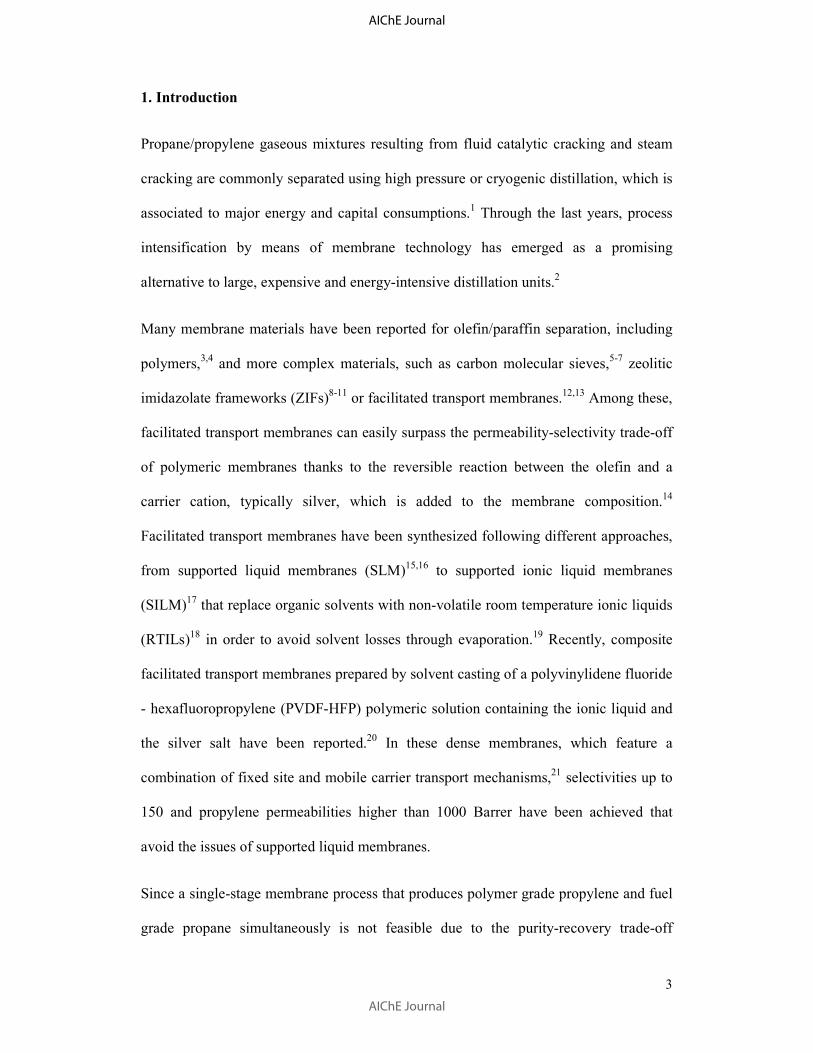
3
1. Introduction
Propane/propylene gaseous mixtures resulting from fluid catalytic cracking and steam
cracking are commonly separated using high pressure or cryogenic distillation, which is
associated to major energy and capital consumptions.1 Through the last years, process
intensification by means of membrane technology has emerged as a promising
alternative to large, expensive and energy-intensive distillation units.2
Many membrane materials have been reported for olefin/paraffin separation, including
polymers,3,4
and more complex materials, such as carbon molecular sieves,5-7
zeolitic
imidazolate frameworks (ZIFs)8-11 or facilitated transport membranes.12,13 Among these,
facilitated transport membranes can easily surpass the permeability-selectivity trade-off
of polymeric membranes thanks to the reversible reaction between the olefin and a
carrier cation, typically silver, which is added to the membrane composition.14
Facilitated transport membranes have been synthesized following different approaches,
from supported liquid membranes (SLM)15,16 to supported ionic liquid membranes
(SILM)17 that replace organic solvents with non-volatile room temperature ionic liquids
(RTILs)18 in order to avoid solvent losses through evaporation.19 Recently, composite
facilitated transport membranes prepared by solvent casting of a polyvinylidene fluoride
- hexafluoropropylene (PVDF-HFP) polymeric solution containing the ionic liquid and
the silver salt have been reported.20 In these dense membranes, which feature a
combination of fixed site and mobile carrier transport mechanisms,21 selectivities up to
150 and propylene permeabilities higher than 1000 Barrer have been achieved that
avoid the issues of supported liquid membranes.
Since a single-stage membrane process that produces polymer grade propylene and fuel
grade propane simultaneously is not feasible due to the purity-recovery trade-off
AIChE Journal
AIChE Journal
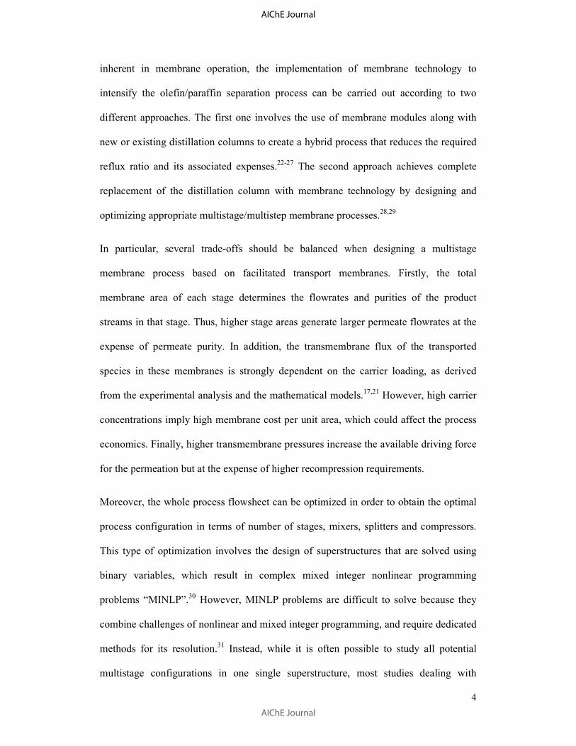
4
inherent in membrane operation, the implementation of membrane technology to
intensify the olefin/paraffin separation process can be carried out according to two
different approaches. The first one involves the use of membrane modules along with
new or existing distillation columns to create a hybrid process that reduces the required
reflux ratio and its associated expenses.22-27 The second approach achieves complete
replacement of the distillation column with membrane technology by designing and
optimizing appropriate multistage/multistep membrane processes.28,29
In particular, several trade-offs should be balanced when designing a multistage
membrane process based on facilitated transport membranes. Firstly, the total
membrane area of each stage determines the flowrates and purities of the product
streams in that stage. Thus, higher stage areas generate larger permeate flowrates at the
expense of permeate purity. In addition, the transmembrane flux of the transported
species in these membranes is strongly dependent on the carrier loading, as derived
from the experimental analysis and the mathematical models.17,21 However, high carrier
concentrations imply high membrane cost per unit area, which could affect the process
economics. Finally, higher transmembrane pressures increase the available driving force
for the permeation but at the expense of higher recompression requirements.
Moreover, the whole process flowsheet can be optimized in order to obtain the optimal
process configuration in terms of number of stages, mixers, splitters and compressors.
This type of optimization involves the design of superstructures that are solved using
binary variables, which result in complex mixed integer nonlinear programming
problems “MINLP”.30 However, MINLP problems are difficult to solve because they
combine challenges of nonlinear and mixed integer programming, and require dedicated
methods for its resolution.31 Instead, while it is often possible to study all potential
multistage configurations in one single superstructure, most studies dealing with
AIChE Journal
AIChE Journal
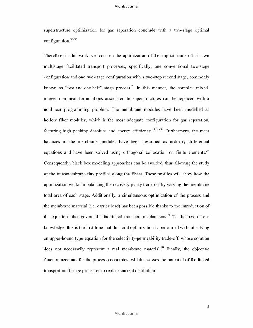
5
superstructure optimization for gas separation conclude with a two-stage optimal
configuration.32-35
Therefore, in this work we focus on the optimization of the implicit trade-offs in two
multistage facilitated transport processes, specifically, one conventional two-stage
configuration and one two-stage configuration with a two-step second stage, commonly
known as “two-and-one-half” stage process.28 In this manner, the complex mixed-
integer nonlinear formulations associated to superstructures can be replaced with a
nonlinear programming problem. The membrane modules have been modelled as
hollow fiber modules, which is the most adequate configuration for gas separation,
featuring high packing densities and energy efficiency.34,36-38 Furthermore, the mass
balances in the membrane modules have been described as ordinary differential
equations and have been solved using orthogonal collocation on finite elements.39
Consequently, black box modeling approaches can be avoided, thus allowing the study
of the transmembrane flux profiles along the fibers. These profiles will show how the
optimization works in balancing the recovery-purity trade-off by varying the membrane
total area of each stage. Additionally, a simultaneous optimization of the process and
the membrane material (i.e. carrier load) has been possible thanks to the introduction of
the equations that govern the facilitated transport mechanisms.21
To the best of our
knowledge, this is the first time that this joint optimization is performed without solving
an upper-bound type equation for the selectivity-permeability trade-off, whose solution
does not necessarily represent a real membrane material.40 Finally, the objective
function accounts for the process economics, which assesses the potential of facilitated
transport multistage processes to replace current distillation.
AIChE Journal
AIChE Journal
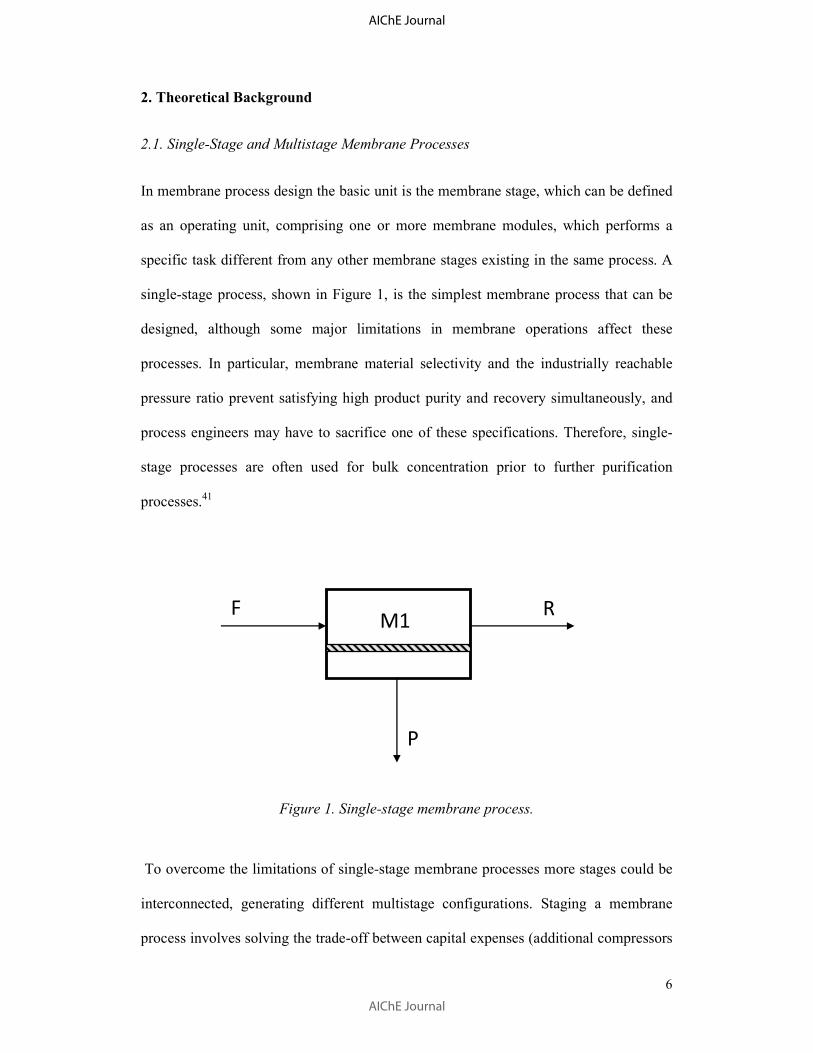
6
2. Theoretical Background
2.1. Single-Stage and Multistage Membrane Processes
In membrane process design the basic unit is the membrane stage, which can be defined
as an operating unit, comprising one or more membrane modules, which performs a
specific task different from any other membrane stages existing in the same process. A
single-stage process, shown in Figure 1, is the simplest membrane process that can be
designed, although some major limitations in membrane operations affect these
processes. In particular, membrane material selectivity and the industrially reachable
pressure ratio prevent satisfying high product purity and recovery simultaneously, and
process engineers may have to sacrifice one of these specifications. Therefore, single-
stage processes are often used for bulk concentration prior to further purification
processes.41
Figure 1. Single-stage membrane process.
To overcome the limitations of single-stage membrane processes more stages could be
interconnected, generating different multistage configurations. Staging a membrane
process involves solving the trade-off between capital expenses (additional compressors
F R
P
M1
AIChE Journal
AIChE Journal

7
and membrane modules) and product recovery. Although there are many multistage
configurations, the two-stage and the so-called two-and-one-half stage processes,42 are
preferred over three stage or higher multistage processes.28 In the two-stage process,
shown in Figure 2, the recompressed permeate of the first stage is fed into a second
stage for a further purification step. The retentate of the second stage is then recycled
and mixed with the original feed.
Figure 2. Two-step membrane process.
In comparison, the two-and-one-half process shown in Figure 3 uses a two-step
separation for the second stage and the permeate of the second step is recycled to the
first step feed. This configuration can achieve any desired concentration of the more
permeable gas by controlling the relative size of the second stage modules. Moreover, to
balance the tradeoffs and calculate the feed and permeate pressures and the membrane
area of each stage, process optimization is required.
AIChE Journal
AIChE Journal

8
Figure 3. Two-and-one-half membrane process.
2.2. Discretized membrane model
Previous studies on membrane process optimization usually make use of simplified
membrane models. These shortcut models are typically implemented within
superstructures that are solved as mixed-integer optimization problems.32 For processes
where a more detailed description of the membrane separator is needed as in the case of
hollow fibers modules, a perfect cross-flow model is usually employed. This model
assumes plug-flow in the high pressure side of the fiber, usually the lumen side, and
perfect mixed flow in the permeate side, i.e. shell side.23 However, assuming that the
feed flows through the lumen side may seem unrealistic in gas separation hollow fibers,
whereby the active layer is often formed in the outer fiber surface. In addition, most
membrane models assume fixed permeability/selectivity values for a given membrane
material. In contrast, the rigorous facilitated transport model used in this work requires
calculating the partial pressure profiles along the module. To address these issues, a
fully discretized optimization model has been developed in this work.
AIChE Journal
AIChE Journal
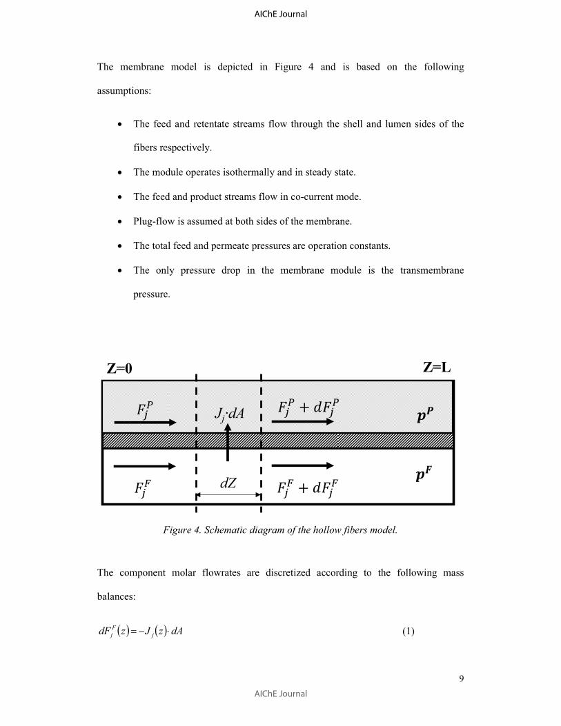
9
The membrane model is depicted in Figure 4 and is based on the following
assumptions:
• The feed and retentate streams flow through the shell and lumen sides of the
fibers respectively.
• The module operates isothermally and in steady state.
• The feed and product streams flow in co-current mode.
• Plug-flow is assumed at both sides of the membrane.
• The total feed and permeate pressures are operation constants.
• The only pressure drop in the membrane module is the transmembrane
pressure.
Figure 4. Schematic diagram of the hollow fibers model.
The component molar flowrates are discretized according to the following mass
balances:
( ) ( ) dAzJzdF j
F
j ⋅−= (1)
dZ
Z=0 Z=L
Jj·dA
AIChE Journal
AIChE Journal

10
( ) ( ) dAzJzdF j
P
j ⋅= (2)
where jF and �� are the molar flowrate and the transmembrane flux of component �,
respectively, and dA is the fiber outer wall area differential element. The dimensionless
fiber axial length is defined as:
L
zz = [ ]1,0∈z (3)
where L is the total fiber length. Rearranging terms, the mass balances (ODEs) and the
boundary conditions can now be rewritten as:
����(̅)�̅ = −��(�̅) · � (4)
����(̅)�̅ = ��(�̅) · � (5)
���|̅�� = ���(�̅ = 0) (6)
���|̅�� = ���(�̅ = 1) (7)
One of the main features of this work is that the membrane material optimization (i.e.
carrier concentration) and the multistage process optimization are performed
simultaneously. For this purpose, the rigorous facilitated transport model previously
developed by this research group has been implemented in the optimization,21
particularly for PVDF-HFP/BMImBF4/AgBF4 membranes containing silver as carrier.
In this model, which was specifically developed for facilitated transport membranes that
combine fixed and mobile carrier mechanisms, the permeability of the paraffin can be
considered constant. Thus its transmembrane flux is described through the solution-
diffusion model:43
AIChE Journal
AIChE Journal

11
�����(�̅) =����� !"����� (�̅) − "����� (�̅)# (8)
where $���� is the paraffin permeability, % is the active layer thickness and "����� and
"����� are the feed and permeate partial pressure of the paraffin.
Conversely, the olefin flux, i.e. the preferentially transported species, is affected by the
complexation reaction with the silver cations:
&�'() + +,-./0123�'((+,-.) (9)
The flux can be calculated as the sum of the contributions of three transport
mechanisms: solution-diffusion, fixed-site carrier and mobile carrier:
����4(�̅) = ����4,67(�̅) + ����4,8�(�̅) + ����4,��(�̅) (10)
����4,67(�̅) = 9���4,: · ;���4,:<���4� (̅)=<���4� (̅)
(11)
����4,8�(�̅) =/01·&>?)·����4
�(/01·<����� (̅)·����49@A:<
<���4� (̅)=<���4� (̅) BCD (12)
����4,8�(�̅) = E��(�̅) · <���4� (̅)=<���4� (̅) (1 − BCD) (13)
E��(�̅) = F G !>?H#�(/I<���4� (̅)J (14)
where KLM is the complexation constant, -���4 is the propylene solubility in the
composite membrane, BCD is the ionic liquid mass fraction in the membrane
composition, F is a fitting parameter for the fixed-site carrier mechanism and &�'N) isthe silver concentration in the membrane. The temperature dependencies have been
AIChE Journal
AIChE Journal

12
omitted as isothermal operation has been assumed. The contribution of the Fickian
diffusion to the olefin transmembrane flux (Eq.11) is negligible compared to the
contribution of the facilitated transport mechanisms (Eq. 12-13) and, in consequence, it
has not been included in the optimization. A detailed description of the model can be
found in the original source.21 Table 1 shows the values of the model parameters.
Table 1. Facilitated transport model parameters at 323 K.
Parameter Value Reference
Dcomp (x1011
m2 s
-1) 4.30 [17]
BCD (-) 0.20 [21]
-���4(mol bar-1 m-3) 31.97 [18]
keq (m3 mol-1) 0.17 [18]
α (x1011 m2 mol-1 s-1) 2.37 [21]
As commented before, the use of this specific model for facilitated transport avoids
using a fixed permeability parameter and introduces carrier concentration as a decision
variable. In this way, the membrane material and the multistage process can be
optimized at the same time.
Finally, the ordinary differential equations (Eqs 4-7) are solved as algebraic equations
after discretization through implicit Runge-Kutta collocation methods using 100 finite
elements and 3 internal collocation points.
2.3. Optimization details
The aim of this work is to optimize two multistage membrane processes: a) a two-stage
and b) a two-and-one-half stage, intended to produce polymer grade propylene, and
AIChE Journal
AIChE Journal

13
enriched propane, from a C3 refinery stream minimizing the Net Present Value Costs
(NPVC) of both configurations. The pressure, temperature and composition of the
original feed, stream F in Figures 1-3, are fixed by common refinery specifications.44
Table 2 displays the properties of the propylene/propane mixed stream, the target
product purities and the process constants and constraints.
Table 2. Process feed specifications, parameters and constraints.
Parameter Value
Feed temperature (K) 323
Feed pressure (bar) 18
Feed flowrate (kmol h-1) 360
Feed composition (C3H6 mole frac.) 0.50
Permeate pressure (bar) 1-18
Required C3H6 purity (xi) ≥ 0.995
Required C3H8 purity (xi) ≥ 0.950
C3H8 permeability (Barrer) a
20
Membrane thickness (µm) 20
Silver loadingb (M) 0-6
a 1 Barrer = 10−10 cm3 (STP) cm cm−2 s−1 cmHg−1.
b Silver loading delimited according to the experimentally studied concentration range.20,21
The decision variables of the model are:
• The membrane area of each module.
• The carrier concentration of each membrane.
• The permeate pressure.
AIChE Journal
AIChE Journal
14
The mathematical standard form of the optimization problem can be described as:
PQRQSQ�TU$V+(W)X. Z.
ℎ(W) = 0Z(W) ≥ 0
]^ ≤ W ≤ ]"
(15)
where v is the vector of decision variables, )(vh represents the set of model algebraic
equations, )(vt is the set of constraints (Eqs. 16-17) and ]^and ]" are the lower and
upper limits of the decision variables, respectively.
B���4 ≥ B���4,:ab (16)
B���� ≥ B����,:ab (17)
Finally, the objective function (NPVC) has been calculated as a combination of OPEX
and CAPEX, correcting the operating expenses according to the time value of money:
U$V+ = +�$cd + e$cd · (1 − (1 + f)=N) f⁄ (18)
The parameters and constants used are shown in Table 3. A detailed description of the
economic calculations can be found in a previous work.45 Briefly, the compressor
expenses have been calculated according to the Guthrie’s Modular Method for Costing
and Sizing 46 and the membrane cost is calculated using the market prices for its
constituents and the optimized composition:
P+� = % · ($h · $$ + ihh · ih$ + &�')( · P>? · �j$) (19)
where P+� is the membrane cost per unit area, δ is the membrane thickness and P>? is
the molar mass of AgBF4. The membrane replacement cost has been introduced through
a membrane replacement factor Pk.
AIChE Journal
AIChE Journal

15
Table 3. Economic evaluation parameters.
Parameter Symbol Value
Membrane
Membrane replacement factor (%) MR 1
Polymer load (g m-3) PL 1.11x10⁶
Ionic liquid load (g m-3) ILL 2.76x10⁵
Polymer cost ($ g-1) PP 0.7
Ionic liquid cost ($ g-1) ILP 0.8
Silver salt cost ($ g-1
) AGP 13.0
Compressor
Compressor stages Nst 3
Cost function exponent a 0.77
Electricity price ($ kWh-1) EP 0.15
Isentropic efficiency ηc 0.70
Material and pressure factor MPF 1
Compression ratio Crmax 2.62
Module factor MF 3.11
Ratio of heat capacities ϒ 1.15
Reference cost ($) C0 23000
Reference size (kW) S0 74.57
Update factor UF 4.71
Project
Annual operation (h y-1
) OF 8000
Investment rate (%) r 10
Period (y) labm 15
The optimization model renders a NLP problem solved in GAMS using as solver the
multi-start heuristic algorithm OQNLP on a 3.40 GHz Intel® Core™ i7–3770
processor. The model statistics are detailed in Table 4. The model is solved in less than
0.1 seconds when CONOPT is used as local solver for OQNLP.
Table 4. Models statistics
Two-stages Two-and-one-half stages
Number of single equations 4314 8122
Number of single variables 4321 8130
AIChE Journal
AIChE Journal

16
3. Results and Discussion
This section presents and discusses the main results regarding the design and
optimization of the proposed flowsheets. The feed stream to both flowsheets consists of
an equimolar propane/propylene mixture and the objective is to obtain propylene and
propane purities of 99.5 mol% and 95 mol% respectively. The Net Present Value Cost
(NPVC) of both multistage processes will be compared with the NPVC of the reference
distillation column.
3.1. Multistage membrane process optimization results
The optimized two stage flowsheet is displayed in Figure 5. The optimal design
comprises two membrane stages showing considerable size differences. The first stage
requires more than 14000 m2 of membrane area to generate a propylene depleted
retentate stream, thus achieving the desired propane purity. However, the second stage
area is almost ten times smaller and is intended to produce a high purity propylene
permeate regardless of the retentate purity.
Regarding the optimal carrier loading, its value is allowed to vary between the
experimentally studied range from 0 to 6 M, where 0 M implies no facilitated transport
and 6 M is the highest concentration assessed for PVDF-HFP/BMImBF4/AgBF4
membranes. Eventually, the optimization balances the cost-performance trade-off of the
first stage at 2.51 M Ag+, far below the upper limit. Since higher concentrations of
carrier result in high membrane prices per unit area, this decreased optimal value helps
to reduce the expenses caused by the large size of this stage. On the other hand, the
second stage carrier loading hits the highest allowed level of 6 M Ag+, which is
consistent with the purity-oriented nature of this stage. Although the high carrier
AIChE Journal
AIChE Journal
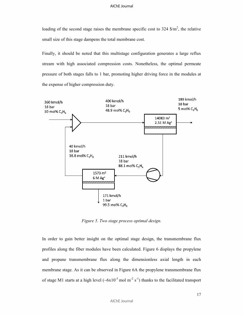
17
loading of the second stage raises the membrane specific cost to 324 $/m2, the relative
small size of this stage dampens the total membrane cost.
Finally, it should be noted that this multistage configuration generates a large reflux
stream with high associated compression costs. Nonetheless, the optimal permeate
pressure of both stages falls to 1 bar, promoting higher driving force in the modules at
the expense of higher compression duty.
Figure 5. Two stage process optimal design.
In order to gain better insight on the optimal stage design, the transmembrane flux
profiles along the fiber modules have been calculated. Figure 6 displays the propylene
and propane transmembrane flux along the dimensionless axial length in each
membrane stage. As it can be observed in Figure 6A the propylene transmembrane flux
of stage M1 starts at a high level (~6x10⁻³ mol m-2 s-1) thanks to the facilitated transport
AIChE Journal
AIChE Journal

18
mechanisms and the significant driving force achieved in the hollow fibers. The
resulting high permeation flux in combination with the large membrane area depletes
the propylene concentration of the retentate stream and, eventually, its driving force
falls until the transmembrane flux of propane (~6x10⁻⁴
mol m-2
s-1
) exceeds that of the
propylene. In contrast, Figure 6B shows the same profiles in stage M2, but in this case
the propylene transmembrane flux remains almost constant due to the reduced
membrane area required, which produces a polymer grade propylene stream as permeate
but maintains a notable propylene concentration in the retentate.
AIChE Journal
AIChE Journal
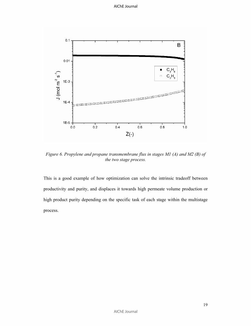
19
Figure 6. Propylene and propane transmembrane flux in stages M1 (A) and M2 (B) of
the two stage process.
This is a good example of how optimization can solve the intrinsic tradeoff between
productivity and purity, and displaces it towards high permeate volume production or
high product purity depending on the specific task of each stage within the multistage
process.
AIChE Journal
AIChE Journal

20
Figure 7. Two-and-one-half stage process optimal design.
The “two-and-one-half stage” process optimization results are shown in Figure 7. The
main feature of this process is the introduction of a third stage intended to recycle a
propylene enriched stream back to the second stage feed, in this manner the outer loop
recycle is reduced, minimizing the total membrane area requirements in the stage M1
and the subsequent compression duty. As in the two stage process, the first stage (M1)
is significantly larger than the next stages (M2 and M3) and its optimal carrier
concentration is below the upper bound, at 2.48 M Ag+. Again, the M2 and M3 stages
require the maximum carrier loading of 6 M Ag+, which increases the membrane
performance at the expense of higher membrane costs. However, although the
introduction of a third stage helps to minimize the compression requirements by
decreasing the recycle flowrate, this reduction is not significant enough and may not
justify its implementation. This can be observed by the relatively small size of stage
M3, which is almost negligible compared with the other stages. The optimization results
of both processes are detailed in Table 5.
AIChE Journal
AIChE Journal
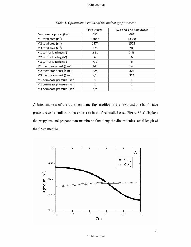
21
Table 5. Optimization results of the multistage processes
Two Stages Two-and-one-half Stages
Compressor power (kW) 697 688
M1 total area (m2) 14083 13338
M2 total area (m2) 1574 1575
M3 total area (m2) n/a 206
M1 carrier loading (M) 2.51 2.48
M2 carrier loading (M) 6 6
M3 carrier loading (M) n/a 6
M1 membrane cost ($ m-2
) 147 145
M2 membrane cost ($ m-2) 324 324
M3 membrane cost ($ m-2) n/a 324
M1 permeate pressure (bar) 1 1
M2 permeate pressure (bar) 1 1
M3 permeate pressure (bar) n/a 1
A brief analysis of the transmembrane flux profiles in the “two-and-one-half” stage
process reveals similar design criteria as in the first studied case. Figure 8A-C displays
the propylene and propane transmembrane flux along the dimensionless axial length of
the fibers module.
AIChE Journal
AIChE Journal
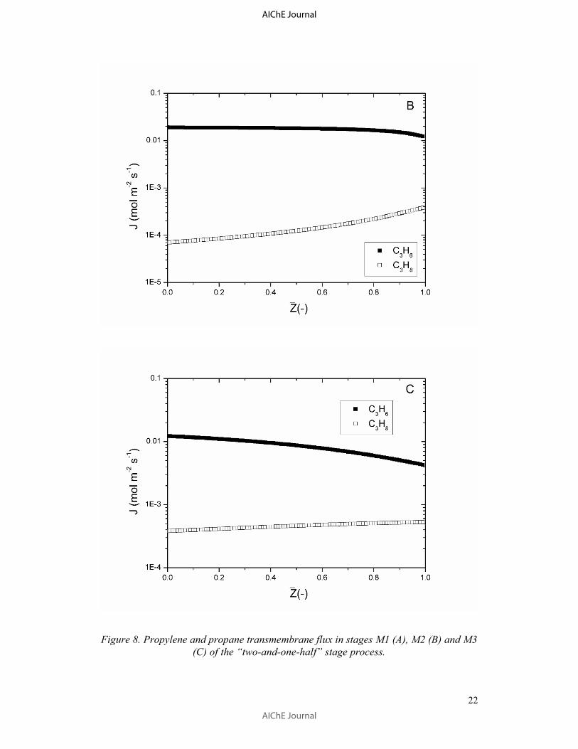
22
Figure 8. Propylene and propane transmembrane flux in stages M1 (A), M2 (B) and M3
(C) of the “two-and-one-half” stage process.
AIChE Journal
AIChE Journal

23
As commented before, the large membrane area required in the first stage is intended to
achieve the desired propane purity in one single pass, as a result, most of the propylene
permeates and its driving force is reduced until its transmembrane flux falls below the
propane level, see Figure 8A. Notice that this is not detrimental when the product
stream is the retentate, as is the case for stage M1. However, the subsequent stages,
Figures 8B-C, are intended to produce a propylene-enriched permeate and consequently,
the propylene transmembrane flux remains high along the fiber modules, thanks to the
relatively small areas involved in these stages.
3.2. NPVC comparison
The NPVC of both membrane processes and the base case distillation are itemized in
Table 6. The results reveal the prominent potential of facilitated transport membrane
processes to replace the traditional distillation and to sharply decrease the investment
expenses when implementing the two stage membrane process. On the other hand, the
introduction of an additional separation step in the “two-and-one-half” stage flowsheet
produces minor savings compared to the two stages process and, therefore, a less
complex process may be preferred. It is worth noting that the main difference between
the base case distillation and the membrane processes is not in the capital expenses but
in the operating costs, which is consistent with the use of process steam in the
distillation reboiler. As expected, process intensification through membrane technology
plays here a major role in energy saving.
Table 6. Multistage processes Net Present Value Cost compared to the distillation base
case.
Distillation Two Stages "Two-and-one-half" Stages
OPEX (MM$ y-1) 4.1a 0.86 0.85
CAPEX (MM$) 8.9a 5.0 4.9
NPVC (MM$) 39.7a 11.56 11.40
a Calculated according to the “Guthrie’s Modular Method for Costing and Sizing” 46 based on the design parameters presented elsewhere.24
AIChE Journal
AIChE Journal
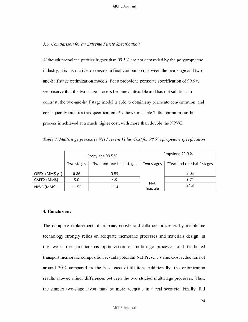
24
3.3. Comparison for an Extreme Purity Specification
Although propylene purities higher than 99.5% are not demanded by the polypropylene
industry, it is instructive to consider a final comparison between the two-stage and two-
and-half stage optimization models. For a propylene permeate specification of 99.9%
we observe that the two stage process becomes infeasible and has not solution. In
contrast, the two-and-half stage model is able to obtain any permeate concentration, and
consequently satisfies this specification. As shown in Table 7, the optimum for this
process is achieved at a much higher cost, with more than double the NPVC.
Table 7. Multistage processes Net Present Value Cost for 99.9% propylene specification
Propylene 99.5 % Propylene 99.9 %
Two stages "Two-and-one-half" stages Two stages "Two-and-one-half" stages
OPEX (MM$ y-1
) 0.86 0.85
Not
feasible
2.05
CAPEX (MM$) 5.0 4.9 8.74
NPVC (MM$) 11.56 11.4 24.3
4. Conclusions
The complete replacement of propane/propylene distillation processes by membrane
technology strongly relies on adequate membrane processes and materials design. In
this work, the simultaneous optimization of multistage processes and facilitated
transport membrane composition reveals potential Net Present Value Cost reductions of
around 70% compared to the base case distillation. Additionally, the optimization
results showed minor differences between the two studied multistage processes. Thus,
the simpler two-stage layout may be more adequate in a real scenario. Finally, full
AIChE Journal
AIChE Journal

25
discretization of the model reveals how the recovery-purity trade-off and the position of
each stage within the multistage flowsheet affect the transmembrane flux profiles along
the modules. In this sense, this work outlines the importance of previous mathematical
modeling of transport phenomena as valuable foundations for further computer aided
process engineering.
Acknowledgements
Financial support from the Spanish Ministry of Science under the projects CTQ2015-
66078-R and CTQ2016-75158-R (MINECO, Spain-FEDER 2014–2020) is gratefully
acknowledged. Raúl Zarca also thanks the Universidad de Cantabria for the
postgraduate fellowship.
AIChE Journal
AIChE Journal

26
Nomenclature
A membrane effective area [m2]
D diffusion coefficient [m2 s
-1]
F molar flowrate [mol s-1]
H Henry’s solubility constant [mol bar-1 m-3]
h set of model algebraic equations
J molar transmembrane flux [mol m-2 s-1]
ELM equilibrium constant [m3 mol-1]
E�� fixed carrier effective permeability [mol bar-1
m-1
s-1
]
E< heterogeneous equilibrium constant [bar-1]
L fiber length [m]
P permeability [mol bar-1 m-1 s-1]
p pressure [bar]
R universal gas constant [8.314 J mol-1
K-1
]
r investment rate [%]
S gas solubility in the membrane [mol bar-1 m-3]
T investment period [y]
t set of model constraints
U’ lower limit of the decision variables
AIChE Journal
AIChE Journal

27
U” upper limit of the decision variables
x molar fraction [-]
BCD ionic liquid mass fraction [-]
z hollow fiber axial dimension [m]
Greek letter
α fitting parameter
δ active layer thickness [m]
Superscript / subscript
0 feed side
C3H6 propylene
C3H8 propane
comp organometallic complex
FC fixed-site carrier
IL ionic liquid
L permeate side
m membrane
MC mobile carrier
r reaction
SD solution-diffusion
AIChE Journal
AIChE Journal

28
References
1. Sholl DS, Lively RP. Seven chemical separations to change the world. Nature.
2016;532(7600):435-437.
2. Charpentier JC. In the frame of globalization and sustainability, process
intensification, a path to the future of chemical and process engineering
(molecules into money). Chem Eng J. 2007;134(1-3):84-92.
3. Faiz R, Li K. Polymeric membranes for light olefin/paraffin separation.
Desalination. 2012;287:82-97.
4. Staudt-Bickel C, Koros WJ. Olefin/paraffin gas separations with 6FDA-based
polyimide membranes. J Membr Sci. 2000;170(2):205-214.
5. Xu L, Rungta M, Brayden MK, et al. Olefins-selective asymmetric carbon
molecular sieve hollow fiber membranes for hybrid membrane-distillation
processes for olefin/paraffin separations. J Membr Sci. 2012;423-424:314-323.
6. Liu J, Liu Y, Kayrak Talay D, Calverley E, Brayden M, Martinez M. A new
carbon molecular sieve for propylene/propane separations. Carbon.
2015;85:201-211.
7. Xiaoli M, Lin YS, Wei X, Kniep J. Ultrathin Carbon Molecular Sieve
Membrane for Propylene/Propane Separation. AIChE J. 2016;62(2):491-499.
8. Kwon HT, Jeong HK, Lee AS, An HS, Lee JS. Heteroepitaxially Grown Zeolitic
Imidazolate Framework Membranes with Unprecedented Propylene/Propane
Separation Performances. J Am Chem Soc. 2015;137(38):12304-12311.
AIChE Journal
AIChE Journal

29
9. Liu D, Ma X, Xi H, Lin YS. Gas transport properties and propylene/propane
separation characteristics of ZIF-8 membranes. J Membr Sci. 2014;451:85-93.
10. An H, Park S, Kwon HT, Jeong HK, Lee JS. A new superior competitor for
exceptional propylene/propane separations: ZIF-67 containing mixed matrix
membranes. J Membr Sci. 2017;526:367-376.
11. Da Silva FA, Rodrigues AE. Propylene/propane separation by vacuum swing
adsorption using 13X zeolite. AIChE J. 2001;47(2):341-357.
12. Faiz R, Li K. Olefin/paraffin separation using membrane based facilitated
transport/chemical absorption techniques. Chem Eng Sci. 2012;73:261-284.
13. Yoon Y, Won J, Kang YS. Polymer electrolyte membranes containing silver ion
for facilitated olefin transport. Macromolecules. 2000;33(9):3185-3186.
14. Nymeijer K, Visser T, Brilman W, Wessling M. Analysis of the Complexation
Reaction between Ag+ and Ethylene. Ind Eng Chem Res. 2004;43(11):2627-
2635.
15. Duan S, Ito A, Ohkawa A. Separation of propylene/propane mixture by a
supported liquid membrane containing triethylene glycol and a silver salt. J
Membr Sci. 2003;215(1-2):53-60.
16. Ravanchi MT, Kaghazchi T, Kargari A. Supported liquid membrane separation
of propylene-propane mixtures using a metal ion carrier. Desalination.
2010;250(1):130-135.
AIChE Journal
AIChE Journal
30
17. Fallanza M, Ortiz A, Gorri D, Ortiz I. Experimental study of the separation of
propane/propylene mixtures by supported ionic liquid membranes containing
Ag+–RTILs as carrier. Sep Purif Technol. 2012;97:83-89.
18. Ortiz A, Ruiz A, Gorri D, Ortiz I. Room temperature ionic liquid with silver salt
as efficient reaction media for propylene/propane separation: Absorption
equilibrium. Sep Purif Technol. 2008;63(2):311-318.
19. Teramoto M, Matsuyama H, Yamashiro T, Katayama Y. Separation of Ethylene
From Ethane By Supported Liquid Membranes Containing Silver-Nitrate As a
Carrier. J Chem Eng Japan. 1986;19:419-424.
20. Fallanza M, Ortiz A, Gorri D, Ortiz I. Polymer-ionic liquid composite
membranes for propane/propylene separation by facilitated transport. J Membr
Sci. 2013;444:164-172.
21. Zarca R, Ortiz A, Gorri D, Ortiz I. Generalized predictive modeling for
facilitated transport membranes accounting for fixed and mobile carriers. J
Membr Sci. 2017;542(August):168-176.
22. Kookos IK. Optimal design of membrane/distillation column hybrid processes.
Ind Eng Chem Res. 2003;42(8):1731-1738.
23. Caballero JA, Grossmann IE, Keyvani M, Lenz ES, Square N, Pennsyl V.
Design of hybrid distillation - vapor membrane separation systems. Ind Eng
Chem Res. 2009;48:9151-9162.
24. Zarca R, Ortiz A, Gorri D, Biegler LT, Ortiz I. Optimized Distillation Coupled
With State-of-the-Art Membranes for Propylene Purification. J Membr Sci.
2018;556:321-328.
AIChE Journal
AIChE Journal

31
25. Tula AK, Befort B, Garg N, Camarda K V., Gani R. Sustainable process design
& analysis of hybrid separations. Comput Chem Eng. 2017;105:96-104.
26. Eliceche AM, Daviou MC, Hoch PM, Ortiz I. Optimisation of azeotropic
distillation columns combined with pervaporation membranes. Comput Chem
Eng. 2002;26(4-5):563-573.
27. Pressly TG, Ng KM. A Break-Even Analysis of Distillation-Membrane Hybrids.
AIChE J. 1998;44(1):93-105.
28. Baker RW. Membrane Technology and Applications. 3rd ed. Chichester: Wiley;
2012.
29. Ahmad F, Lau KK, Shariff AM, Murshid G. Process simulation and optimal
design of membrane separation system for CO2 capture from natural gas.
Comput Chem Eng. 2012;36(1):119-128.
30. Qi R, Henson MA. Membrane system design for multicomponent gas mixtures
via mixed-integer nonlinear programming. Comput Chem Eng.
2000;24(12):2719-2737.
31. Zhou K, Chen X, Shao Z, Wan W, Biegler LT. Heterogeneous parallel method
for mixed integer nonlinear programming. Comput Chem Eng. 2014;66:290-
0300.
32. Ohs B, Lohaus J, Wessling M. Optimization of membrane based nitrogen
removal from natural gas. J Membr Sci. 2016;498:291-301.
33. Kunde C, Kienle A. Global optimization of multistage binary separation
networks. Chem Eng Process. 2018;131: 164-177.
AIChE Journal
AIChE Journal

32
34. Nymeijer DC, Visser T, Assen R, Wessling M. Composite hollow fiber gas-
liquid membrane contactors for olefin/paraffin separation. Sep Purif Technol.
2004;37(3):209-220.
35. Aliaga-Vicente A, Caballero JA, Fernandez-Torres MJ. Synthesis and
optimization of membrane cascade for gas separation via mixed-integer
nonlinear programming. AIChE J. 2017;63(6):1989-2006.
36. Coker DT, Freeman BD, Fleming GK. Modeling multicomponent gas separation
using hollow-fiber membrane contactors. AIChE J. 1998;44(6):1289-1302.
37. Gilassi S, Taghavi SM, Rodrigue D, Kaliaguine S. Simulation of gas separation
using partial element stage cut modeling of hollow fiber membrane modules.
AIChE J. 2017;64(5): 1766-1777.
38. Pan CY. Gas separation by high‐flux, asymmetric hollow‐fiber membrane.
AIChE J. 1986;32(12):2020-2027.
39. Marriott JI, Sørensen E, Bogle IDL. Detailed mathematical modeling of
membrane modules. Comput Chem Eng. 2001;25:693–700.
40. Burns RL, Koros WJ. Defining the challenges for C3H6/C3H8 separation using
polymeric membranes. J Membr Sci. 2003;211(2):299-309.
41. Spillman R. Economics of gas separation membrane processes. In: Noble RD,
Stern SA, eds. Membrane Separations Technology. Principles and Applications.
Amsterdam: Elsevier Science; 1995.
42. Baker RW, Wijmans JG. Two-stage Membrane Process and Apparatus. US
Patents 5,256,295 and 5,256,296, 1993.
AIChE Journal
AIChE Journal
33
43. Wijmans JG, Baker RW. The solution-diffusion model: a review. J Membr Sci.
1995;107(1-2):1-21.
44. Luyben WL. Dynamic simulation of flooded condensers. Chem Eng Res Des.
2017;118:12-20.
45. Zarca G, Urtiaga A, Biegler LT, Ortiz I. An optimization model for assessment
of membrane-based post-combustion gas upcycling into hydrogen or syngas. J
Memb Sci. 2018;563:83-92.
46. Biegler LT, Grossmann IE, Westerberg AW. Systematic methods of chemical
process design. Upper Saddle River, NJ: Prentice Hall PTR; 1997.
AIChE Journal
AIChE Journal

1
Comprehensive study on PVDF-HFP/BMImBF4/AgBF4 membranes for propylene
purification
Authors: Raúl Zarca1, Antoniel Carlos C. Campos2, Alfredo Ortiz1, Daniel Gorri1,
Inmaculada Ortiz1*.
1Department of Chemical and Biomolecular Engineering. University of Cantabria, Av.
Los Castros 46, 39005 Santander, Spain
2Institute of Chemistry, Rio de Janeiro State University (UERJ), Campus Maracanã, P H
L C, São Francisco Xavier St., 524, Rio de Janeiro, RJ, Brazil, 20550-900.
*corresponding author: [email protected]
Journal of Membrane Science
July 2018

2
Abstract
In this work, a comprehensive analysis of PVDF-HFP/BMImBF4/AgBF4 facilitated
transport membranes for olefin/paraffin separation is presented. Previous works of our
research group have reported high flux and propylene selectivity under dry conditions
and using synthetic gas mixtures, highlighting the promising potential of these
membranes for industrial applications. This work advances in the understanding of the
phenomena involved in membrane performance and moves one step forward in the
knowledge of the industrial viability of this membrane system. First, the internal
interactions between the silver cations and the polymer backbone, the silver salt
dissociation and the silver degradation have been studied using FTIR, Raman and XPS
spectroscopic techniques. Secondly, the experimental membrane performance during 110
days and working at changing relative humidity conditions in the feed gas has been
assessed. Thermogravimetric techniques helped determining the water uptake capability
of the facilitated transport membrane. Thirdly, real gas mixtures from a fluid catalytic
cracking unit were provided by the industry and used in permeation experiments to check
the membrane behavior under industrial-like conditions. The results provide experimental
evidence for the previously theorized facilitated transport mechanisms and reveal a major
influence of feed gas humidity on membrane performance. On the other hand, the
industrial gas mixture produces no deviation from synthetic feed conditions due to trace
contaminants. Finally, the carrier deactivation in long-term permeation has been
quantified through a mathematical expression.
Keywords
Propylene, membrane, facilitated transport, humidity, real gas mixture, silver
degradation.
3
1. Introduction
The separation of propane/propylene mixtures is one of the most costly processes in the
petrochemical industry, caused by the similar physicochemical properties of both species,
which requires the use of energy intensive cryogenic or high pressure distillation [1].
Among the most promising alternatives to traditional distillation, membrane technology
offers a compact, modular and simple operation, allowing for process intensification [2].
In the last years, facilitated transport membranes have demonstrated exceptional
separation performance in terms of permeability and selectivity [3]. These membranes
make use of transition metal cations, typically silver, that can selectively and reversibly
react with the olefin according to the Dewar-Chatt-Duncanson model [4,5]. This principle
has been implemented in different configurations in recent times. The most basic
approach consists in filling the pores of a polymeric support with a liquid solution of the
carrier salt. However, this supported liquid membranes (SLM) lack from stability due to
solvent evaporation and dragging [6–9]. Although the use of novel ionic liquids has
overcome the solvent evaporation problems, the expelling out of solvent from the pores
due to the transmembrane pressure is still a major drawback [10–13]. Proper mechanical
stability and separation performance can be achieved combining the properties of dense
membranes with facilitated transport through the synthesis of polymer/salt systems. In
these systems, the silver salt is dissolved along with the polymer and the membrane is
then fabricated through solvent casting [14], which results in a dense facilitated transport
membrane usually described as a polymer electrolyte [15–17]. The internal structure and
olefin/paraffin separation performance of these systems have been studied rather
extensively in oxygen-containing polar polymers such as poly(2-oxazoline) POZ,
poly(vinyl alcohol) (PVA) and poly(vinyl pyrrolidone) (PVP) [18–20]. Additionally,
several studies have assessed the potential of these electrolytes for energy applications

4
using fluoropolymers and lithium salt blends [21,22]. However, deeper knowledge on
fluoropolymer-silver salt interactions is required in order to fully understand its gas
separation potential.
In this regard, recent works of our research group have demonstrated the promising
performance of fluoropolymer/silver salt membranes containing imidazolium based ionic
liquids [23–25]. The presence of the ionic liquid, a non-volatile additive, serves two
purposes: it helps stabilizing the silver cations, partially mitigating the carrier deactivation
issues [5,26,27], and it acts as a fluid medium that enables mobile carrier transport. In
these works, 1-butyl-3-methylimidazolium tetrafluoroborate (BMImBF4) ionic liquid is
used for its affinity to olefinic compounds and for having the same anion as the silver salt,
which reduces the system complexity [28]. Poly(vinylidene fluoride-co-
hexafluoropropylene) PVDF-HFP is selected for its high thermal, chemical and
mechanical stability. In addition, it contains fluorine atoms that are likely to form weak
interactions with the Ag+ cations according to the Pearson’s Hard-Soft–Acid-Base
(HSAB) theory [29], which gives rise to fixed site carrier transport. AgBF4 is used as
carrier precursor because the lattice energy of BF4- anion is low enough to allow the
olefin-silver complexation [30]. However, the internal interactions caused by the
complexity of this membrane system and its responses to changes in the feed humidity
conditions are still unclear. Furthermore, few studies assess the performance of silver-
containing membranes in the long-term, and what is more important, there is a lack of
information regarding permeation of real gas mixtures provided by the industry, which is
especially critical given the instability issues caused by silver reduction.
In this work, the internal structure of the PVDF-HFP/BMImBF4/AgBF4 membrane is
assessed implementing various spectroscopic techniques. Moreover, the long-term
membrane stability is studied performing a 110 days-long permeation experiment, and

5
the influence of the feed relative humidity on the membrane performance is explored and
quantified by modifying the feed humidification conditions. Finally, the behavior of these
membranes under real conditions is studied permeating a FCC refinery gas mixture
provided by the industry.
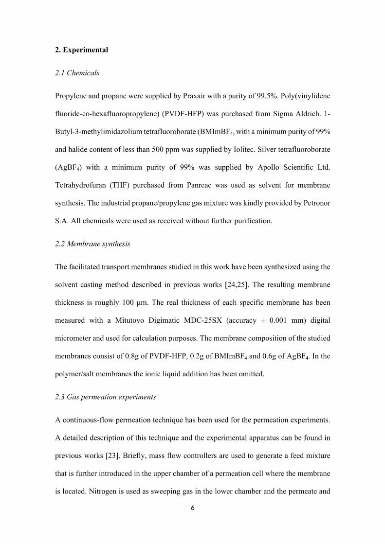
6
2. Experimental
2.1 Chemicals
Propylene and propane were supplied by Praxair with a purity of 99.5%. Poly(vinylidene
fluoride-co-hexafluoropropylene) (PVDF-HFP) was purchased from Sigma Aldrich. 1-
Butyl-3-methylimidazolium tetrafluoroborate (BMImBF4) with a minimum purity of 99%
and halide content of less than 500 ppm was supplied by Iolitec. Silver tetrafluoroborate
(AgBF4) with a minimum purity of 99% was supplied by Apollo Scientific Ltd.
Tetrahydrofuran (THF) purchased from Panreac was used as solvent for membrane
synthesis. The industrial propane/propylene gas mixture was kindly provided by Petronor
S.A. All chemicals were used as received without further purification.
2.2 Membrane synthesis
The facilitated transport membranes studied in this work have been synthesized using the
solvent casting method described in previous works [24,25]. The resulting membrane
thickness is roughly 100 μm. The real thickness of each specific membrane has been
measured with a Mitutoyo Digimatic MDC-25SX (accuracy ± 0.001 mm) digital
micrometer and used for calculation purposes. The membrane composition of the studied
membranes consist of 0.8g of PVDF-HFP, 0.2g of BMImBF4 and 0.6g of AgBF4. In the
polymer/salt membranes the ionic liquid addition has been omitted.
2.3 Gas permeation experiments
A continuous-flow permeation technique has been used for the permeation experiments.
A detailed description of this technique and the experimental apparatus can be found in
previous works [23]. Briefly, mass flow controllers are used to generate a feed mixture
that is further introduced in the upper chamber of a permeation cell where the membrane
is located. Nitrogen is used as sweeping gas in the lower chamber and the permeate and

7
retentate streams are then analyzed using gas chromatography to determine the
transmembrane flux of each species. However, for humidified feed testing the
experimental apparatus has been modified with the set-up depicted in Figure 1, which
allows generating any desired relative humidity in the feed stream by controlling the ratio
of dry to humidified feed.
GAS A
GAS B
To permeation
cell
Mass flow controllers
Gas bubbler
Figure 1. Set-up for relative humidity control.
The permeation experiments where conducted at the experimental conditions shown in
Table 1.
Table 1. Experimental conditions
Experimental condition Value

8
T (K) 298
Permeation area (cm2) 53
N2 flow (mL min-1) 20-40
C3H6 flow (mL min-1) 20
C3H8 flow (mL min-1) 20
C3H8 /C3H6 feed gas ratio 50:50
Feed side pressure (bar) 1.2
Permeate side pressure (bar) 1
2.4 Membrane characterization techniques
Different characterization techniques were implemented to assess the internal structure,
water uptake capability and carrier degradation of the facilitated transport membranes.
TGA analysis were performed using a TG-DTA 60H Shimadzu thermobalance and
Fourier transform infrared (FTIR) spectra were recorded using a Perkin Elmer Spectrum
Two spectrometer. Additionally, Raman spectroscopy was carried out using a Horiba
T64000 triple spectrometer equipped with a confocal microscope and a Jobin Yvon
Symphony CCD detector cooled with liquid nitrogen. A 488 nm beam from a Kr-Ar ion
laser was focused through a 100x objective, using 2 mW laser power in all measurements.
The spectral curves were fitted using Lorentzian functions. Finally, XPS spectra were
acquired using an SPECS (Berlin, Germany) X-ray photoelectron spectrometer. The
samples were analyzed using an Mg anode operated at 225 W (E=1253.6 eV, 13 kV, 17.5
mA). The carbon (C 1s) line at 284.8 eV was used as the reference in our determinations
of the binding energies of the silver. A scanning interval of 0.1 eV was used for the final
spectrum acquisition.

9
3. Results
3.1 Thermogravimetric analysis
The thermal analysis has been performed to assess the potential water uptake of the
studied membranes. Figure 2 displays the thermogravimetric curves of PVDF-HFP,
PVDF-HFP/AgBF4 and PVDF-HFP/BMImBF4/AgBF4 membranes.
Figure 2. TGA curves of the studied membranes.
The membrane samples were vacuum dried at 30 mbar and 298 K for 24 hours after
casting to completely remove the remaining solvent. Prior to testing the samples were
exposed to ambient moisture (~80% RH at room temperature) for 24 hours. In this
manner, any water loss appearing at the beginning of the temperature ramp can be
attributed to water evaporation. According to Figure 2, the pure polymer membrane
exhibits no weight loss until it reaches its degradation temperature around 680 K, which
reveals no water uptake. This is in good agreement with the hydrophobic nature of the

10
fluoropolymer [31]. However, Figure 2 shows prominent mass losses of the silver-
containing membranes in the 300-436 K temperature range. Thus, it can be concluded
that the addition of the AgBF4 salt to the membrane composition dramatically changes
the nature of the facilitated transport membranes due to its high hygroscopicity, which
results in water uptakes of around 25 wt% when exposed to moist conditions.
3.2 Fourier transform infrared spectroscopy (FTIR)
The interaction between the Ag+ cations and the fluorine atoms of the polymer chains can
be studied through infrared spectroscopy analyzing the polymer CF2 symmetrical
stretching mode and comparing that of the pure polymer with the silver-containing
membranes, see Figure 3.
Figure 3. FTIR spectra of the studied membranes.
The CF2 peak of the pure polymer appears in the 1178 cm-1 band. After incorporation of
the silver salt, the stretching band shifted to 1174 and 1172 cm-1 in the PVDF-HFP/AgBF4

11
and PVDF-HFP/BMImBF4/AgBF4 respectively. This shift to lower wavelength indicates
a weakening of the C-F bond caused by the interaction of silver cations with the fluorine
atoms of the fluoropolymer, which is the basis of the fixed site carrier transport
mechanism. This phenomenon has been previously studied by Chang and Kang (2016)
using FTIR on PVDF-HFP/HBF4 polymer electrolytes [32].
3.3 RAMAN spectroscopy
Better insight on the AgBF4 dissociation behavior can be achieved using Raman
spectroscopy to analyze the regions of the BF4- stretching bands in the pure AgBF4, and
the silver-containing membranes. Figure 4 shows the BF4- stretching band region of
PVDF-HFP/AgBF4 and PVDF-HFP/BMImBF4/AgBF4 membranes. The symmetric
stretching mode of BF4- has been previously reported at 774 cm-1 in the pure AgBF4 [33].
However, the spectrum in Figure 4a shows a wavenumber shift to 767 cm-1 when the
silver is added to the polymer. According to previous studies, this wavenumber
corresponds to free ions [20,34], which means that this change in the Raman spectra is
due to well-dissociated Ag+ cations interacting with the PVDF-HFP backbone.
Furthermore, this wavenumber shift from 774 to 767 cm-1 is still observable after addition
of the ionic liquid BMImBF4, Figure 4b. As the BF4- stretching band also appears at 774
cm-1 in the pure ionic liquid [34], this shift suggests that the ionic liquid is also interacting
with the Ag+ cations and, to a certain extent, with the polymer backbone, as reported by
Fallanza et al. [23].

12
Figure 4. Raman spectra of A) PVDF-HFP /AgBF4 and B) PVDF-
HFP/BMImBF4/AgBF4 membrane.

13
3.4 X-ray photoelectron spectroscopy (XPS)
X-ray photoelectron spectroscopy has been used to expand the knowledge on membrane
structure and degradation. The Ag 3d regions of the XPS spectra can confirm the
interactions between the silver cations and the polymer fluorine atoms. Figure 5 shows
the XPS spectra of a PVDF-HFP/BMImBF4/AgBF4 composite membrane after a long
term permeation experiment (110 days). Table 2 summarizes the two silver species
observable after signal deconvolution. The Ag 3d5/2 band of pure AgBF4 has been
previously reported at 369.2 eV. However, in the composite membrane, the binding
energy has shifted to 368.47 eV. This reduction in the photoelectron binding energy is
caused by the coordination between the silver atoms and the polymer backbone as
demonstrated by Kim et al (2012), who found the same phenomenon for several
AgBF4/polymer blends [35]. Additionally, a second silver species (Ag 3d5/2=368.26 Ag
3d3/2=374.25) is associated with the presence of metallic silver [36], presumably due to
the silver reduction caused by the long term permeation test.
Table 2. XPS regions of PVDF-HFP/BMImBF4/AgBF4 membrane after permeation test.
Region Position
Ag 3d 5/2 368.47Species A
Ag 3d 3/2 374.54
Ag 3d 5/2 368.26Species B
Ag 3d 3/2 374.25

14
CasaXPS (This string can be edited in CasaXPS.DEF/PrintFootNote.txt)
Ag 3d
Ag 3
d
x 103
20
30
40
50
60
70
80
90
100
CPS
385 380 375 370 365 360 355Binding Energy (eV)
Figure 5. XPS spectra of the PVDF-HFP/BMImBF4/AgBF4 membrane after permeation
test.
3.5 Long-term permeation under humid conditions
Figure 6 shows a 110 days long-term permeation test on a PVDF-HFP/BMImBF4/AgBF4
facilitated transport composite membrane. The feed gas consisted of an equimolar
propane/propylene mixture at 1.2 bar total pressure. The main goal of this experiment is
to determine the separation behavior of a composite membrane over an extended period
of time, assessing both the feed gas relative humidity effect and the possible loss of
performance due to carrier deactivation. Figure 6 is divided into five sections (I-V)
accounting for the relative humidity conditions and following the sequence of the
experimental runs. A characteristic feature of this facilitated transport membranes under
dry conditions is a sharp decrease of the permeation flux in the first operating hours

15
ostensibly caused by the rapid loss of water and residual solvent by evaporation, Figure
7 (section II). At the beginning of the test (section I) the humidity was kept at saturation
and no flux decay was observed during the first 5 days, which confirms that the
characteristic curve observed under dry gas conditions is due to solvent and water
moisture evaporation. From day 5 to day 27 some instability in membrane performance
occurred due to controlled changes in the temperature and pressure conditions within the
experiments. In Figure 6 this is more evident for the propane flux due to the semi-
logarithmic scale.
Figure 6. Long term permeation experiment of PVDF-HFP/BMImBF4/AgBF4 composite
membrane at 298 K and 1.2 bar feed pressure (C3H8/C3H6 50:50) under different
relative humidity conditions.
After 27 days, during section II, the feed was changed to dry gases, which resulted in a
major propane and propylene transmembrane flux decrease as water evaporation occurred
within the membrane. A detailed depiction of the drying curve is shown in Figure 7.

16
Figure 7. Propylene transmembrane flux decrease in section II.
When the humidified gas mixture was fed again into the system (section III), the flux
increase of both gaseous species was almost immediate, reaching the flux values attained
prior to drying. This abrupt increase, noted with red arrows in Figure 6, reveals the
exceptional capability of these membranes to absorb water from the environment. During
sections III, IV and V a feed gas relative humidity of 100, 50 and 25% was used,
respectively. These variations in the humidity conditions resulted in moderate changes in
the propylene transmembrane flux while the propane flux remained almost constant at its
highest level.
However, it should be noted that, apart from the humidity influence, the propylene
transmembrane flux undergoes a continuous slight decrease, evidenced by a constant
slope in Figure 6. On the contrary, the propane flux does not suffer such decrease, which
suggests that this phenomenon is caused by carrier deactivation. Furthermore, it was
17
possible to quantify the deactivation rate by fitting the data for each section (I-V), to an
exponential curve, which yielded the following expression:
(1)𝐽𝐶3𝐻6(𝑡) = 𝐽𝐶3𝐻6(𝑡0)·𝑒 ‒ 5.5𝑥10 ‒ 3·𝑡
where is the initial propylene transmembrane flux at a given temperature, 𝐽𝐶3𝐻6(𝑡0)
pressure and relative humidity conditions and the time t is introduced in days. This
expression allows for membrane lifetime calculation if a minimum required performance
is established.
This carrier deactivation prevents from fitting a mathematical expression for the
propylene flux dependency on relative humidity because each experimental section has
been obtained at different times and, consequently, the propylene flux is not only affected
by the relative humidity but also by the elapsed time from the start of the experiment.
However, using Equation 1, it was possible to project the propylene flux values to a
common initial point. Finally, combining a mathematical expression for the drying curve
(Figure 7) with the propylene flux at each relative humidity, it was possible to obtain a
fitting curve for the propylene transmembrane flux as a function of the relative humidity
(Eq. 2), Figure 8.
(2)𝐽𝐶3𝐻6(𝑅𝐻) = 5.82𝑥10 ‒ 5𝑅𝐻0.49
Figure 8 evidences a sharp increase in the propylene flux with the relative humidity for
RH<10% and a smooth increase after that value (dash line in Figure 8); this finding
supports the fact that even with a low relative humidity in the gaseous feed stream it is
possible to almost saturate the membrane with water. A similar trend has been reported
by Catalano et al. (2012) for oxygen and nitrogen in PFSI membranes [37].

18
Figure 8. Experimental data and mathematical regression for the dependency of the
propylene transmembrane flux on the relative humidity.
Finally, Table 3 displays the permeability and selectivity values of the facilitated transport
membrane for each relative humidity condition. The humidification of the feed gases
produces major changes in the membrane performance, reducing the selectivity and
increasing the permeability of both the olefin and the paraffin. This is a characteristic
effect of water vapor-induced swelling [38,39]. The enlargement of the polymer free
volume caused by the water uptake increases the diffusivity of the gaseous species and
the propylene-silver complex, which leads to notable permeability values but at the
expense of membrane selectivity.
Table 3. Average permeability and selectivity values of the PVDF-HFP/BMImBF4/AgBF4
membrane for each relative humidity during the long-term permeation test.

19
RH (%) P C3H8 (Barrer)a P C3H6 (Barrer) a α C3H6/C3H8 (-)
0 1.2 172 14425 97.3 1032 1150 107.6 1666 16100 106.5 2555 24
a 1 Barrer = 10−10 cm3 (STP) cm cm−2 s−1 cmHg−1.
Although membrane swelling is usually responsible for lowering the polymeric
membranes selectivity below the industrially required values, in this case, the selectivity
remains high enough to consider humid operation as a useful tool to tailor the
permeability-selectivity trade-off. Thus, wet gas could be implemented as a controlling
agent when productivity is preferred over product purity. In this way, multistage
membrane processes performing a refining separation after a bulk concentration could
modulate the purity-productivity trade-off in each stage by controlling the feed gas
relative humidity [40].
3.6 Industrial gas mixture permeation test
Figure 9 shows the facilitated transport membrane performance when the feed consists of
a real propane/propylene mixture compared with a synthetic gas mixture. The industrial
gas mixture is the product stream of a fluid catalytic cracking unit and its composition is
displayed in Table 4. It mostly consists of a propane/propylene mixture (25:75)
containing minor quantities of light paraffins and olefins.
Table 4. Industrial gas mixture composition.
Component Concentration (mol% )
Methane 0.0034
Ethane 0.1503
Ethylene 0.0099

20
Propane 24.8837
Propylene 74.7208
Isobutane 0.1872
N-butane 0.0016
Trans-butene 0.0214
Iso-butene 0.0218
Hydrogen sulfide < 0.2 ppm
Acetylene < 0.2 ppm
Hydrogen < 0.2 ppm
Figure 9. Synthetic and industrial gas mixture permeation experiments on a PVDF-
HFP/BMImBF4/AgBF4 membrane under dry conditions at 298 K and 1.2 bar total feed
pressure.
Given that both feeds differ in composition, permeability, which is normalized by the
partial pressure gradient, has been plotted instead of the transmembrane flux. Both

21
permeation experiments have been performed under dry conditions to simulate refinery
conditions, hence, both suffer the characteristic permeability decrease due to solvent and
water evaporation in the first hours of operation. Since the propylene transmembrane flux
is similar in both cases, Figure 9 evidences that the membrane performance is not affected
by known contaminant trace components potentially present in industrial streams (i.e.
acetylene, hydrogen sulfide and hydrogen [41]) during the experiment extent.
These results confirm that the prominent separation performance of the studied
membranes is not restricted to laboratory conditions with synthetic gas mixtures and
demonstrate the suitability of these composite facilitated transport membranes to treat
real feed streams.

22
4. Conclusions
The spectroscopic characterization of PVDF-HFP/BMImBF4/AgBF4 membranes used in
the separation of propane/propylene mixtures confirm the existence of weak interactions
between the Ag+ cations and the fluorine atoms of the polymeric backbone, which along
with the addition of ionic liquids result in a hybrid fixed site/mobile carrier transport
mechanism yielding high olefin permeability and selectivity. The long-term permeation
experiment carried out under changing feed gas humidity conditions revealed a slight
permeability decrease due to silver degradation, which is mainly associated to silver
reduction, supported by XPS spectra of the used membrane; this loss of membrane
activity was observed to be independent of the experimental conditions. Although this
degradation is slow enough to allow moderate membrane lifetimes, remediation methods
can be further studied to achieve even larger operating periods. On the other hand, the
humidification of the feed gas can severely alter the membrane performance, increasing
the permeability of the permeant species and decreasing the membrane selectivity due to
water vapor-induced swelling. In this regard, thermogravimetric analysis revealed up to
25 wt% membrane water uptake. Since the membrane showed moderate selectivity even
at saturation, wet gas could be implemented as a controlling agent when productivity is
preferred over product purity. Finally, permeation under real gas conditions revealed no
additional degradation caused by minor contaminants that could potentially affect silver
stability.
Acknowledgements
Financial support from the Spanish Ministry of Science under the projects CTQ 2015-
66078-R and CTQ2016 -75158-R (MINECO, Spain- FEDER 2014–2020) is gratefully
acknowledged. Raúl Zarca also thanks the Universidad de Cantabria for the postgraduate
fellowship.
23
References
[1] D.S. Sholl, R.P. Lively, Seven chemical separations to change the world, Nature.
532 (2016) 435–437.
[2] J.C. Charpentier, In the frame of globalization and sustainability, process
intensification, a path to the future of chemical and process engineering (molecules
into money), Chem. Eng. J. 134 (2007) 84–92.
[3] R. Faiz, K. Li, Olefin/paraffin separation using membrane based facilitated
transport/chemical absorption techniques, Chem. Eng. Sci. 73 (2012) 261–284.
[4] D.J. Safarik, R.B. Eldridge, Olefin/Paraffin Separations by Reactive Absorption:
A Review, Ind. Eng. Chem. Res. 37 (1998) 2571–2581.
[5] A. Ortiz, L.M. Galán, D. Gorri, A.B. De Haan, I. Ortiz, Kinetics of reactive
absorption of propylene in RTIL-Ag+ media, Sep. Purif. Technol. 73 (2010) 106–
113.
[6] M.T. Ravanchi, T. Kaghazchi, A. Kargari, Supported liquid membrane separation
of propylene-propane mixtures using a metal ion carrier, Desalination. 250 (2010)
130–135.
[7] S. Azizi, T. Kaghazchi, A. Kargari, Propylene/propane separation using N-methyl
pyrrolidone/AgNO3 supported liquid membrane, J. Taiwan Inst. Chem. Eng. 57
(2015) 1–8.
[8] M. Teramoto, H. Matsuyama, T. Yamashiro, Y. Katayama, Separation of Ethylene
From Ethane By Supported Liquid Membranes Containing Silver-Nitrate As a
Carrier, J. Chem. Eng. Japan. 19 (1986) 419–424.
[9] S. Duan, A. Ito, A. Ohkawa, Separation of propylene/propane mixture by a
24
supported liquid membrane containing triethylene glycol and a silver salt, J.
Memb. Sci. 215 (2003) 53–60.
[10] M. Fallanza, A. Ortiz, D. Gorri, I. Ortiz, Experimental study of the separation of
propane/propylene mixtures by supported ionic liquid membranes containing
Ag+–RTILs as carrier, Sep. Purif. Technol. 97 (2012) 83–89.
[11] G. Zarca, I. Ortiz, A. Urtiaga, Copper(I)-containing supported ionic liquid
membranes for carbon monoxide/nitrogen separation, J. Memb. Sci. 438 (2013)
38–45.
[12] R. Fortunato, C.A.M. Afonso, M.A.M. Reis, J.G. Crespo, Supported liquid
membranes using ionic liquids: Study of stability and transport mechanisms, J.
Memb. Sci. 242 (2004) 197–209.
[13] P. Scovazzo, Testing and evaluation of room temperature ionic liquid (RTIL)
membranes for gas dehumidification, J. Memb. Sci. 355 (2010) 7–17.
[14] R. Zarca, A. Ortiz, D. Gorri, I. Ortiz, Facilitated Transport of Propylene Through
Composite Polymer-Ionic Liquid Membranes. Mass Transfer Analysis, Chem.
Prod. Process Model. 11 (2016) 77–81.
[15] Y. Yoon, J. Won, Y.S. Kang, Polymer electrolyte membranes containing silver ion
for facilitated olefin transport, Macromolecules. 33 (2000) 3185–3186.
[16] H. Kataoka, Y. Saito, M. Tabuchi, Y. Wada, T. Sakai, Ionic conduction mechanism
of PEO-type polymer electrolytes investigated by the carrier diffusion
phenomenon using PGSE-NMR, Macromolecules. 35 (2002) 6239–6244.
[17] L. Liu, X. Feng, A. Chakma, Unusual behavior of poly(ethylene oxide)/AgBF4
polymer electrolyte membranes for olefin-paraffin separation, Sep. Purif. Technol.
25
38 (2004) 255–263.
[18] S.U. Hong, J.H. Jin, J. Won, Y.S. Kang, Polymer-salt complexes containing silver
ions and their application to facilitated olefin transport membranes, Adv. Mater.
12 (2000) 968–971.
[19] J.H. Kim, B.R. Min, K.B. Lee, J. Won, Y.S. Kang, Coordination structure of
various ligands in crosslinked PVA to silver ions for facilitated olefin transport,
Chem. Commun. 2 (2002) 2732–2733.
[20] Y.S. Park, S. Chun, Y.S. Kang, S.W. Kang, Durable poly(vinyl
alcohol)/AgBF4/Al(NO3)3 complex membrane with high permeance for
propylene/propane separation, Sep. Purif. Technol. 174 (2017) 39–43.
[21] T. Liu, Z. Chang, Y. Yin, K. Chen, Y. Zhang, X. Zhang, The PVDF-HFP gel
polymer electrolyte for Li-O2 battery, Solid State Ionics. 318 (2018) 88–94.
[22] S. Abbrent, J. Plestil, D. Hlavata, J. Lindgren, J. Tegenfeldt, Å. Wendsjö,
Crystallinity and morphology of PVdF–HFP-based gel electrolytes, Polymer
(Guildf). 42 (2001) 1407–1416.
[23] M. Fallanza, A. Ortiz, D. Gorri, I. Ortiz, Polymer-ionic liquid composite
membranes for propane/propylene separation by facilitated transport, J. Memb.
Sci. 444 (2013) 164–172.
[24] R. Zarca, A. Ortiz, D. Gorri, I. Ortiz, Generalized predictive modeling for
facilitated transport membranes accounting for fixed and mobile carriers, J. Memb.
Sci. 542 (2017) 168–176.
[25] R. Zarca, A. Ortiz, D. Gorri, I. Ortiz, A practical approach to fixed-site-carrier
facilitated transport modeling for the separation of propylene/propane mixtures

26
through silver-containing polymeric membranes, Sep. Purif. Technol. 180 (2017)
82–89.
[26] A. Ortiz, L. Galán, D. Gorri, B. De Haan, I. Ortiz, Reactive Ionic Liquid Media for
the Separation of Propylene / Propane Gaseous Mixtures, Ind. Eng. Chem. Res. 49
(2010) 7227–7233.
[27] A. Ortiz, A. Ruiz, D. Gorri, I. Ortiz, Room temperature ionic liquid with silver salt
as efficient reaction media for propylene/propane separation: Absorption
equilibrium, Sep. Purif. Technol. 63 (2008) 311–318.
[28] M. Fallanza, M. González-Miquel, E. Ruiz, A. Ortiz, D. Gorri, J. Palomar, I. Ortiz,
Screening of RTILs for propane/propylene separation using COSMO-RS
methodology, Chem. Eng. J. 220 (2013) 284–293.
[29] R.G. Pearson, Hard and Soft Acids and Bases, J. Am. Chem. Soc. 85 (1963) 3533–
3539.
[30] C.K. Kim, J. Won, H.S. Kim, Y.S. Kang, H.G. Li, C.K. Kim, Density functional
theory studies on the dissociation energies of metallic salts: Relationship between
lattice and dissociation energies, J. Comput. Chem. 22 (2001) 827–834.
[31] X. Tian, X. Jiang, Poly(vinylidene fluoride-co-hexafluoropropene) (PVDF-HFP)
membranes for ethyl acetate removal from water, J. Hazard. Mater. 153 (2008)
128–135.
[32] J. Chang, S.W. Kang, CO2 separation through poly(vinylidene fluoride-co-
hexafluoropropylene) membrane by selective ion channel formed by
tetrafluoroboric acid, Chem. Eng. J. 306 (2016) 1189–1192.
[33] E. Goreshnik, Z. Mazej, X-ray single crystal structure and vibrational spectra of

27
AgBF4, Solid State Sci. 7 (2005) 1225–1229.
[34] D. Ji, Y.S. Kang, S.W. Kang, Accelerated CO2 transport on surface of AgO
nanoparticles in ionic liquid BMIMBF4, Sci. Rep. 5 (2015) 16362.
[35] J.H. Kim, S.W. Kang, Y.S. Kang, Threshold silver concentration for facilitated
olefin transport in polymer/silver salt membranes, J. Polym. Res. 19 (2012) 9753.
[36] T.C. Kaspar, T. Droubay, S.A. Chambers, P.S. Bagus, Spectroscopic Evidence for
Ag(III) in Highly Oxidized Silver Films by X-ray Photoelectron Spectroscopy, J.
Phys. Chem. C. 114 (2010) 21562–21571.
[37] J. Catalano, T. Myezwa, M.G. De Angelis, M.G. Baschetti, G.C. Sarti, The effect
of relative humidity on the gas permeability and swelling in PFSI membranes, Int.
J. Hydrogen Energy. 37 (2012) 6308–6316.
[38] W.S. Ho, D.C. Dalrymple, Facilitated transport of olefins in Ag+-containing
polymer membranes, J. Memb. Sci. 91 (1994) 13–25.
[39] S. Hong, Effect of water on the facilitated transport of olefins through solid
polymer electrolyte membranes, J. Memb. Sci. 181 (2001) 289–293.
[40] R. Zarca, A. Ortiz, D. Gorri, L.T. Biegler, I. Ortiz, Optimized Distillation Coupled
With State-of-the-Art Membranes for Propylene Purification, J. Memb. Sci. 556
(2018) 321–328.
[41] T.C. Merkel, R. Blanc, I. Ciobanu, B. Firat, A. Suwarlim, J. Zeid, Silver salt
facilitated transport membranes for olefin/paraffin separations: Carrier instability
and a novel regeneration method, J. Memb. Sci. 447 (2013) 177–189.


Appendices
201
A.2 Contributions to scientific meetings 1- Highlighting the benefits of using state-of-the-art membranes in the propylene production through process optimization. R. Zarca, A. Ortiz, D. Gorri, L.T. Biegler, I. Ortiz. Euromembrane Conference 2018. Valencia (Spain). July 2018. Poster. 2- Performance of new composite facilitated transport membranes for olefin/paraffin separation. R. Zarca, A. Ortiz, D. Gorri, I. Ortiz. 10th World Congress on Chemical Engineering (WCCE10). Barcelona (Spain). October 2017. Oral presentation. 3- Ethane/ethylene separation through facilitated transport ionic liquid composite membranes. R. Zarca, A. Ortiz, D. Gorri, I. Ortiz. 5th Iberoamerican Meeting on Ionic Liquids (IMIL 2017). Sao Paulo (Brasil). April 2017. Oral presentation. 4- High performance facilitated transport composite membranes for real industrial olefin/paraffin separation. R. Zarca, M. Fallanza, A. Ortiz, D. Gorri, I. Ortiz. International Congress on Membranes and Membrane Processes (ICOM 2017). San Francisco (USA). July-August 2017. Oral presentation. 5- Propane/propylene separation through facilitated transport composite membranes. R. Zarca, A. Ortiz, D. Gorri, I. Ortiz. European Membrane Society Summer School 2016. Bertinoro (Italy). June-July 2016. Poster. 6- Assessment of mass transfer parameters in olefin facilitated transport through polymer-ionic liquid composite membranes. D. Gorri, R. Zarca, A. Ortiz, I. Ortiz. International Conference on Properties and Phase Equilibria for Product and Process Design (PPEPPD 2016). Oporto (Portugal). May 2016. Poster. 7- Propane/propylene separation through facilitated transport composite membranes. A. Ortiz, R. Zarca, D. Gorri, I. Ortiz. X Ibero-American Conference on Membrane Science and Technology (CITEM 2016). Ciudad de México (México). May 2016. Poster. 8- Facilitated transport of propylene through composite polymer-ionic liquid membranes. Mass transfer analysis. A. Ortiz, R. Zarca, D. Gorri, I. Ortiz. 12th International Conference on Membrane Science and

Appendices
202
Technology (MST 2015). Teheran (Iran). November 2015. Oral presentation. 9- Mass transfer analysis in the facilitated transport of propylene through composite polymer-ionic liquid membranes. R. Zarca, A. Ortiz, D. Gorri, I. Ortiz. Euromembrane Conference 2015. Aachen (Germany). September 2015. Oral presentation. 10- Facilitated transport composite membranes base on polymer-ionic liquids-Ag+ for propane/propylene separation. R. Zarca, A. Ortiz, D. Gorri, I. Ortiz. Iberoamerican Meeting on Ionic Liquids 2015 (IMIL 2015) Madrid (Spain). July 2015. Poster. 11- Polymer-ionic liquids-Ag+ composite membranes for propane/propylene separation. R. Zarca, A. Ortiz, D. Gorri, I. Ortiz. European Membrane Society Summer School 2015. Liberec (Czech Republic). June 2015. Poster. 12- Polymer/ionic liquid composite membranes for olefin selective separation. D. Gorri, R. Zarca, A. Ortiz, I. Ortiz. 20th International Solvent Extraction Conference 2014 (ISEC). Würzburg (Germany). September 2014. Oral presentation. 13- Testing the permeability of highly selective ionic liquid/polymer composite membranes for light hydrocarbons. R. Zarca, A. Ortiz, D. Gorri, I. Ortiz. II International Congress of Chemical Engineering of ANQUE (ICCE). Madrid (Spain). July 2014. Poster. 14- Highly selective ionic liquid/polymer composite membranes for propylene/propane separation. A. Ortiz, R. Zarca, D. Gorri, I. Ortiz. 2nd International Conference on Ionic Liquids in Separation and Purification Technology (ILSEPT 2014). Toronto (Canada). June 2014. Oral presentation. 15- Permeability of propane and propylene in highly selective ionic liquid/polymer composite membranes. R. Zarca, A. Ortiz, D. Gorri, I. Ortiz. IX Ibero-American Conference on Membrane Science and Technology (CITEM 2014). Santander (Spain). May 2014. Poster and oral presentation.
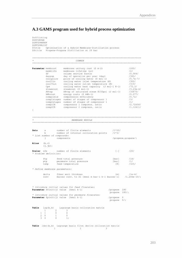
Appendices
203
A.3 GAMS program used for hybrid process optimization $offlisting $OFFUPPER $OFFSYMXREF $OFFSYMLIST $Title Optimization of a Hybrid Membrane-Distillation process $Stitle Propene-Propane Distillation at 20 bar ******************************************************************************** * COMMON ******************************************************************************** Parameter membcost membrane unitary cost ($ m-2) /200/ memblife membrane lifetime (yr) /2/ SF column service factor /0.904/ daysop day of operation per year (day) /365/ coolprice price of cooling water ($ mol-1) /5.7e-7/ coolTin cooling water inlet temperature (K) /300/ coolTout cooling water outlet temperature (K) /319/ Cpw cooling water heat capacity (J mol-1 K-1) /75.3/ steamcost steamcost ($ mol-1) /3.23e-4/ AHvap AHvap of saturated steam @150psi (J mol-1) /35870/ kWhcost energy costs ($ kWh-1) /0.077/ compyield compressors efficiency /0.72/ comp1stages number of stages of compressor 1 /3/ comp2stages number of stages of compressor 1 /1/ comp1CR compressor 1 compress. ratio /2.72658/ comp2CR compressor 2 compress. ratio /1.12611/ ; ******************************************************************************** * MEMBRANE MODULE ******************************************************************************** Sets a number of finite elements /1*20/ b number of internal collocation points /1*3/ * List number of compounds: j components /propene,propane/; Alias (b,c) (j,jb); Scalar nfe number of finite elements [-] /20/ * Problem definition: ftp feed total pressure [bar] /18/ ptp permeate total pressure [bar] /1/ temp feed temperature [K] /325/ * Define membrane parameters: delta fiber wall thicknes [m] /1e-6/ conv Barrer conv. to SI [kmol m bar-1 h-1 Barrer-1] /1.206e-10/; * Introduce initial values for feed flowrates: Parameter ffinit(j) value [kmol h-1] /propene 180 propane 180/; * Introduce initial values for permeate flowrates: Parameter fpinit(j) value [kmol h-1] /propene 0 propane 0/; Table lag(b,b) Lagrange basis collocation matrix 1 2 3 1 1 0 0 2 0 1 0 3 0 0 1; Table ldot(b,b) Lagrange basis first derivs collocation matrix 1 2 3

Appendices
204
1 -5.999997202501304 -3.464098384864128 3.464098384864127 2 6.464099408820847 2.999996178544585 -6.464099408820847 3 -0.464102206319543 0.464102206319543 3.000001023956719; Parameter lfinal(b) value /1 1 2 -1.732051615138131 3 1.732051615138131/; Parameter fffinal(j,a) final molar retentate flowrate fpfinal(j,a) final molar permeate flowrate h(a); h(a) = 1/nfe; Variables ff(j,a,b) retentate molar flowrate fp(j,a,b) permeate molar flowrate ffdot(j,a,b) ff first order derivative fpdot(j,a,b) fp first order derivative ll(a,b) fiber lenght area membrane area [*10^-3 m2] theta dimensionless area [-] gammap permeate over feed pressure [-] ; ******************************************************************************** * DISTILLATION COLUMN ******************************************************************************** $ontext ----------------------------------------------------------------------- Section 1 Basic Data ___________ Basic Thermodynamic Data have been taken from R.C. Reid, J.M. Prausnitz and B.E. Poling : " The Properties of gases and liquids " 4th Edition, McGraw-Hill (1987) $offtext $ontext Units: Pressure : in bars i.e. 0.1 Mpa Temperature : in kelvins Heat capacity : kJ/kmol K Abbreviations : mm Molar mass Tb Normal boiling point Tc Critical temperature Pc Critical Pressure Omega Acentric factor Liq-den Density of liquid at Tden $offtext Table PRCON (J,*) Basic Physical Properties mm Tb Tc Pc Omega Liq-den Tden Propene 42.081 225.4 364.9 46.0 0.142 0.867 293 Propane 44.097 231.0 369.8 42.4 0.152 0.885 289 Table VPCON(J,*) Constants in the wagner equation for vap.pressure A B C D TMIN Propene -6.64231 1.21857 -1.81005 -2.48212 309 Propane -6.68770 1.24880 -1.97450 -2.05390 288 Table CPCON(J,*) Constants for the isobaric heat capacity equation A B C D Propene 3.188e1 3.237e-2 3.898e-4 -4.999e-7 Propane 3.199e1 4.266e-2 4.998e-4 -6.563e-7

Appendices
205
Parameter dhv(j) Heat of vapourization (kj kmol-1) --- assumed to be constant / Propene 18700 Propane 18800 / ; *dhv from Stephenson and Malanowski, 1987. $Ontext Section 2 _________ In this section, we derive approximate representations for heat capacities and enthalpies for the pure components. $Offtext Scalars Treb Guess temp. for reboiler Tbot Guess temp. for bottom-most tray Ttop Guess temp. for top-most tray Tcon Guess temp. for condenser ; treb = 330; tbot = 328; ttop = 324; tcon = 322; Scalar rg Universal gas constant /8.314/ ; Parameters cpvu(j),cpvl(j), cplu(j), cpll(j), dcpl(j),dcpv(j) ; cpvu(j) = treb*(cpcon(j,'b') + treb*( cpcon(j,'c') +treb *cpcon(j,'d'))) + cpcon(j,'a') ; cpvl(j) = tcon*(cpcon(j,'b') + tcon*( cpcon(j,'c') +tcon *cpcon(j,'d'))) + cpcon(j,'a') ; cplu(j) = cpvu(j) + rg *( 1.45 + 0.45 * (1 - treb/prcon(j,'tc'))**(-1) + 0.25 * prcon(j,'omega') * (17.11 + 25.2 *( ( 1 - treb/prcon(j,'tc'))**(1.0/3)) * (treb/prcon(j,'tc'))**(-1) + 1.742 * (1 - treb/prcon(j,'tc'))**(-1) ) ) ; cpll(j) = cpvl(j) + rg *( 1.45 + 0.45 * (1 - tcon/prcon(j,'tc'))**(-1) + 0.25 * prcon(j,'omega') * (17.11 + 25.2 * (( 1 - tcon/prcon(j,'tc'))**(1.0/3)) * (tcon/prcon(j,'tc'))**(-1) + 1.742 * (1 - tcon/prcon(j,'tc'))**(-1) ) ) ; dcpl(j) = (cplu(j)-cpll(j))/(treb - tcon) ; dcpv(j) = (cpvu(j)-cpvl(j))/(treb - tcon) ; display cpvu ; display cpvl ; display cplu ; display cpll ; display dcpl ; display dcpv ; $ontext Final expressions for enthalpy Note: Liquid enthalpy will be computed as cpll(j) (t -tcon) + 0.5 * dcpl(j) *(t-tcon)**2 = hl0(j) + hla(j)*t + hlb(j)* t**2 Note: Vapour enthalpy will be computed as hl0(j) + hla(j)*prcon(j,'tb') + hlb(j) * (prcon(j,'tb')**2) + dhv(j) + cpvl(j)*(t -prcon(j,'tb')) + 0.5 * dcpv(j)*(t-prcon(j,'tb'))**2 = hv0(j) + hva(j) *t + hvb(j) * t**2 $offtext Parameters hl0(j) ,hla(j), hlb(j) See description above; hl0(j) = tcon *( -cpll(j) + tcon *dcpl(j)/2); hla(j) = cpll(j) - dcpl(j)*tcon; hlb(j) = dcpl(j)/2; display hl0 ; display hla ; display hlb ; Parameters hv0(j),hva(j),hvb(j) See description above; hv0(j) = hl0(j) + hla(j)*prcon(j,'tb') + hlb(j)*(prcon(j,'tb')**2) +dhv(j) - cpvl(j)*prcon(j,'tb') + 0.5 *dcpv(j)*(prcon(j,'tb')**2) ;

Appendices
206
hva(j) = cpvl(j) - dcpv(j)*prcon(j,'tb') ; hvb(j) = dcpv(j)/2 ; display hv0 ; display hva ; display hvb ; $ontext Section 3 _________ In this section we derive simplified expression for the vapour pressure. The preferred form is : ln( pvap(j)) = a(j) - b(j)/T ; (T in kelvins) ; $offtext Parameters vpl(j),vpu(j), av(j), bv(j), xtreb(j), xtcon(j) ; xtreb(j) = 1 - treb/prcon(j,'tc'); xtcon(j) = 1 - tcon/prcon(j,'tc'); vpu(j) = log(prcon(j,'pc')) + prcon(j,'tc')/treb * (vpcon(j,'a')*xtreb(j) + vpcon(j,'b')*xtreb(j)**1.5 +vpcon(j,'c')*xtreb(j)**3 +vpcon(j,'d')*xtreb(j)**6); vpl(j) = log(prcon(j,'pc')) + prcon(j,'tc')/tcon * (vpcon(j,'a')*xtcon(j) + vpcon(j,'b')*xtcon(j)**1.5 +vpcon(j,'c')*xtcon(j)**3 +vpcon(j,'d')*xtcon(j)**6); bv(j) = (vpu(j) -vpl(j))/(1/tcon - 1/treb) ; av(j) = (vpu(j)*treb - vpl(j)*tcon)/(treb-tcon) ; display vpu , vpl ; display av , bv ; $ontext Section 4 _________ Thermal condition of the feed stream $offtext Scalars tf temperature of the feed (in kelvins) pf pressure of the feed stream vf vapour fraction in feed(before expansion) preb Pressure in the reboiler pbot Pressure in the bottom-most tray ptop Pressure in the top-most tray pcon Pressure in the condenser ; preb = 20.41 ; pbot = 20.27; ptop = 19.05; pcon = 19.05; tf = 323 ; pf = 20.27 ; Parameters vpf(j) vapour pressures at feed temperatures ; Positive Variables fdp Total no. of moles of feed permeate fdr Total no. of moles of feed retentate xfp(j) molefractions in feed-stream permeate xfr(j) molefractions in feed-stream retentate Shfp Specific Enthalpy of feed permeate Shfr Specific Enthalpy of feed retentate rebKW reboiler total duty condKW condenser total duty membdev membrane devaluation comp1costyr permeate recompression total cost comp2costyr retentate recompression total cost comp1eleckw permeate recompression duty comp2eleckw retentate recompression duty rebcostyr reboiler total cost condcostyr condenser total cost alpha(j) selectivity [-] perma permeability ;
Appendices
207
vpf(j) = exp ( av(j) - bv(j)/tf) ; $ontext Section 5 _________ Modelling Equations Note: The enthalpy functions are treated as variables in order to eliminate unnecessary differentiations in Minos Description of the column Note: The stages are numbered bottom upwards (as in the floors of a building). Reboiler is stage(tray) no. 1 and the condenser is the last tray. $offtext Scalar fst location of feed stage /2/; sets i stages /1*135/ reb(i) reboiler con(i) condenser col(i) stages in the col top(i) top-most stage abovef(i) stages above the feed stage belowf(i) feed stage and those below it ; reb(i) = yes$(ord(i) eq 1) ; con(i) = yes$(ord(i) eq card(i)) ; col(i) = yes - (reb(i)+con(i)) ; alias (i,ii,iloop); abovef(i) = yes $(ord(i) gt fst) ; belowf(i) = yes $ (ord(i) le fst ) ; display belowf ; $ontext -------------------------------------------------------------------------------- === Adjust pressures in the column according to the total number of the trays *************************************************************************** * the presures in condenser and the top-most tray are fixed as the same as * specified by original problem. but that in the bottom-most and reboiler * are adjusted by substract the summation of pressures in dried trays from * the original specified values. *************************************************************************** -------------------------------------------------------------------------------- $offtext Parameter p(i) pressure prevailing in tray i ; p(i)$reb(i) = preb ; p(i)$con(i)= pcon ; p(i)$col(i) = pbot - ((pbot-ptop)/(card(i)-1-2)) * (ord(i)-2) ; display p ; parameter pdiff pressure drop of one tray; pdiff = 0; Positive variables pbotm actual pressure in bottom-most tray prebler actual pressure in reboiler; Equations defpbotm defprebler; parameter keq1(i,j); *----------------------------------------------------------------------------------- Scalars hllo,hlhi,hvlo,hvhi limits on enthalpies ; hllo = hl0('propene')+ tcon *(hla('propene') + tcon* hlb('propene')) ; hlhi = hl0('propane')+ treb *(hla('propane') + treb* hlb('propane')) ; hvlo = hv0('propene')+ tcon *(hva('propene') + tcon* hvb('propene')) ;
Appendices
208
hvhi = hv0('propane')+ treb *(hva('propane') + treb* hvb('propane')) ; Scalar sigma feed and reflux deviation parameter; sigma = 0.5; Scalars counter loop counter /1/ purolef purity of propene /0.995/ purpara purity of propane /0.95/; Positive variables slack1(i) slack2(i) dd(i) x(i,j) mole-fraction of j-th component in i-th tray. y(i,j) mole-fraction of j-th component in i-th tray $ontext * ------------------------------------------------------------------- This part is for Continuous Variable Optimization $offtext nfp feed permeate tray location ffp(i) fraction of feed distributed to each tray nfr feed retentate tray location ffr(i) fraction of feed retentate distributed to each tray r reflux ratio Nt reflux tray location g(i) fraction of Reflux distributed to each tray rl(i) fraction of reflux distribution to each tray totalrd total reflux rd portion of total reflux manipulated refcom(j) composition of reflux refhl enthalpy of reflux rdf fraction of reflux manipulated * ------------------------------------------------------------------- l(i) molar flow rate of liquid leaving tray i .(i<n) v(i) molar flow rate of vapour leaving tray i . t(i) temperature of tray i ap1 top product rate ap2 bottom product rate; Variables hl(i),hv(i),objective A10(i,j) A20(i,j) A30(i,j) A11(i,j) A21(i,j) A31(i,j) K0(i,j) K1(i,j) Keq(i,j) ; Scalar smooth; SMOOTH = 100; Positive variables GAMMA(I); Equations IFF(j) IFP(j) ILL FECOLff(j,a,b) FECOLfp(j,a,b) FECOLll(a,b) CONff(j,a) CONfp(j,a) CONll(a) ODEff(j,a,b)

Appendices
209
ODEfp(j,a,b) GROUP_AREA DIM_PRESSURE errk(i) Phase equilibrium error function tmb(i) total material balance for trays in the column tmb1(i) total material balance for reboiler tmbn(i) total material balance for condenser defln(i) definition of l(n) defap1(i) definition of ap1 cmb(i,j) component material balance(1<i<n) cmb1(i,j) component material balance(i=1) cmbn(i,j) component material balance(i=n) phe(i,j) phase equilibrium relation defhl(i) definition of hl(i) defhv(i) definition of hv(i) eb(i) enthalpy balance ddB(i) objpf penalty objective function objs smoothing objective function const1 propene purity constrain const2 propane purity constrain fluxconect feed permeate flux conection compconect feed permeate composition conection fluxconect2 feed retentate flux conection compconect2(j) feed retentate composition conection shfpdef feed permeate enthalpy definition shfrdef feed retentate enthalpy definition distprod distillate production defrebKW definition of reboiler total duty defcondKW definition of condenser total duty defmembdev definition of membrane devaluation defcomp1costyr definition of permeate compressor total cost defcomp2costyr definition of retentate compressor total cost defcomp1eleckw definition of permeate compressor duty defcomp2eleckw definition of retentate compressor duty defrebcostyr definition of reboiler total cost defcondcostyr definition of condenser total cost selectivityfixed fixes alpha propene equal to 1 tradeoff permability-selectivity trade-off defA10(i,j) defA20(i,j) defA30(i,j) defA11(i,j) defA21(i,j) defA31(i,j) defK0(i,j) defK1(i,j) defKeq(i,j) const2 propane purity constrain ; EQUATIONS SMTHL(i) SMOOTHING EQUATION FOR L VALUES SMTHL_r(i) SMOOTHING EQUATION FOR L VALUES SMTHL_pf PENALTY EQUATION FOR L VALUES SMTHV(i) SMOOTHING EQUATION FOR V VALUES SMTHV_r(i) SMOOTHING EQUATION FOR V VALUES SMTHV_pf PENALTY EQUATION FOR V VALUES * ------------------------------------------------------------ feedeqn(i) feed permeate distribution feedeqn2(i) feed retentate distribution refluxeqn reflux distribution deftotrd define total reflux defrd define portion of total reflux manipulated defrefcom(j) define composition in reflux ; *****************************MEMBRANE EQUATIONS********************************* * SELECTIVITY-PERMEABILITY TRADE-OFF selectivityfixed.. alpha('propene')=e=1; tradeoff.. alpha('propane')=l=97.507*(perma**(-0.362));
Appendices
210
* LAGRANGE BASIS COLLOCATION FECOLff(j,a,b)$(ord(b) gt 1).. h(a)*ffdot(j,a,b) =e= sum(c,ldot(c,b)*ff(j,a,c)); FECOLfp(j,a,b)$(ord(b) gt 1).. h(a)*fpdot(j,a,b) =e= sum(c,ldot(c,b)*fp(j,a,c)); FECOLll(a,b)$(ord(b) gt 1).. h(a) =e= sum(c,ldot(c,b)*ll(a,c)); *CONTINUITY ECUATIONS CONff(j,a)$(ord(a) gt 1).. ff(j,a,'1') =e= sum(b, ff(j,a-1,b)*lfinal(b)); CONfp(j,a)$(ord(a) gt 1).. fp(j,a,'1') =e= sum(b, fp(j,a-1,b)*lfinal(b)); CONll(a)$(ord(a) gt 1).. ll(a,'1') =e= sum(b, ll(a-1,b)*lfinal(b)); *ORDINARY DIFFERENTIAL EQUATIONS ODEff(j,a,b)$(ord(b) gt 1).. ffdot(j,a,b)=e=-theta/alpha(j)* (ff(j,a,b)/(sum(jb,ff(jb,a,b)))- fp(j,a,b)/(sum(jb,fp(jb,a,b)))*gammap); ODEfp(j,a,b)$(ord(b) gt 1).. fpdot(j,a,b)=e=theta/alpha(j)* (ff(j,a,b)/(sum(jb,ff(jb,a,b)))- fp(j,a,b)/(sum(jb,fp(jb,a,b)))*gammap); *ALGEBRAIC EQUATIONS GROUP_AREA.. theta=e=(area*1e3)*(perma*conv)*ftp/delta; DIM_PRESSURE.. gammap=e=ptp/ftp; *INITIAL CONDITIONS IFF(j).. ff(j,'1','1')=e=ffinit(j); IFP(j).. fp(j,'1','1')=e=fpinit(j); ILL.. ll('1','1')=e=0; ******************************************************************************** ***************************MEMBRANE-COLUMN CONECTIONS*************************** fluxconect.. fdp =e=sum(j,sum(b,lfinal(b)*fp(j,'20',b))); fluxconect2.. fdr =e=sum(j,sum(b,lfinal(b)*ff(j,'20',b))); compconect(j).. sum(b,lfinal(b)*fp(j,'20',b))=e=xfp(j)* (sum(b,lfinal(b)*sum(jb,fp(jb,'20',b)))); compconect2(j).. sum(b,lfinal(b)*ff(j,'20',b))=e=xfr(j)* (sum(b,lfinal(b)*sum(jb,ff(jb,'20',b)))); ******************************************************************************** *****************************COLUMN EQUATIONS*********************************** *FEED ENTHALPY shfpdef.. shfp =e= sum(j,xfp(j)*(hl0(j)+tf*(hla(j)+tf*hlb(j)))); shfrdef.. shfr =e= sum(j,xfr(j)*(hl0(j)+tf*(hla(j)+tf*hlb(j)))); *------------------------------------------------------------------------------- feedeqn(i)$col(i).. ffp(i) =E= exp(-sqr((ord(i)-nfp)/sigma))/ sum(ii$col(ii),exp(-sqr((ord(ii)-nfp)/sigma))); feedeqn2(i)$col(i).. ffr(i) =E= exp(-sqr((ord(i)-nfr)/sigma))/ sum(ii$col(ii),exp(-sqr((ord(ii)-nfr)/sigma))); refluxeqn(i)$col(i)..g(i) =E= exp(-sqr((ord(i)-nt)/sigma))/ sum(ii$col(ii),exp(-sqr((ord(ii)-nt)/sigma))); * add a intermediate variable to reduce nonlinearity deftotrd..totalrd - r*ap1 =e= 0;

Appendices
211
defrd..(rd - rdf*totalrd) =e= 0; * we have to cheat Gmas to get specific values on condenser defrefcom(j)..refcom(j) =e= sum(ii$(ord(ii) eq card(ii)), x(ii,j)); defpbotm..pbotm =e= pbot - pdiff*(card(i)-nt); defprebler..prebler =e= preb - pdiff*(card(i) - nt); *------------------------------------------------------------------------------- errk(i).. sum(j,y(i,j)) - sum(j,x(i,j)) =e= 0; tmb1(i)$reb(i).. l(i)+v(i)- l(i+1) =e= 0; *------------------------------------------------------------------------------- tmb(i)$col(i).. l(i) + v(i) - l(i+1) - v(i-1) - ffp(i)*fdp-ffr(i)*fdr - g(i)*rd =e= 0; tmbn(i)$con(i).. ( rd + ap1) - v(i-1) =e= 0; *------------------------------------------------------------------------------- defln(i)$con(i).. l(i) - (totalrd - rd) =e= 0; defap1(i)$reb(i).. l(i) - ap2 =e= 0; *------------------------------------------------------------------------------- cmb(i,j)$col(i).. l(i)*x(i,j) + v(i) *y(i,j) - l(i+1)*x(i+1,j) -v(i-1)*y(i-1,j) - ffp(i)*xfp(j)*fdp - ffr(i)*xfr(j)*fdr - g(i)*rd*refcom(j) =e= 0; *------------------------------------------------------------------------------- cmb1(i,j)$reb(i).. (l(i)*x(i,j) +v(i)*y(i,j)- l(i+1)*x(i+1,j)) =e= 0; *------------------------------------------------------------------------------- cmbn(i,j)$con(i).. (rd + ap1)*x(i,j) - v(i-1)*y(i-1,j) =e= 0; *------------------------------------------------------------------------------- defhl(i).. hl(i)-sum(j,x(i,j)*(hl0(j)+t(i)*(hla(j)+t(i)*hlb(j))))/hvhi =e= 0; defhv(i).. hv(i)-sum(j,y(i,j)*(hv0(j)+t(i)*(hva(j)+t(i)*hvb(j))))/hvhi =e= 0; eb(i)$col(i).. l(i)*hl(i) +v(i)*hv(i) - l(i+1)*hl(i+1) - v(i-1)*hv(i-1) - ffp(i)*fdp* shfp/hvhi - ffr(i)*fdr* shfr/hvhi - g(i)*rd*hl('135') =e= 0; defA10(i,j).. A10(i,j)=e=2.18630+(-8.80971)*t(i)/PRCON (J,'TC')+ 10.96486*power(t(i)/PRCON (J,'TC'),2)+(-3.87905)*power(t(i)/PRCON (J,'TC'),3); defA20(i,j).. A20(i,j)=e=0.30602+(-0.64992)*t(i)/PRCON (J,'TC')+ (-0.72423)*power(t(i)/PRCON (J,'TC'),2)+1.64710*power(t(i)/PRCON (J,'TC'),3); defA30(i,j).. A30(i,j)=e=(-0.02683)+(-0.28575)*t(i)/PRCON (J,'TC')+ 1.09824*power(t(i)/PRCON (J,'TC'),2)+(-0.90820)*power(t(i)/PRCON (J,'TC'),3); defA11(i,j).. A11(i,j)=e=(-3.44761)+14.55943*t(i)/PRCON (J,'TC')+ (-21.31054)*power(t(i)/PRCON (J,'TC'),2)+11.13279*power(t(i)/PRCON (J,'TC'),3); defA21(i,j).. A21(i,j)=e=(-6.40659)+28.27873*t(i)/PRCON (J,'TC')+ (-39.95181)*power(t(i)/PRCON (J,'TC'),2)+17.62137*power(t(i)/PRCON (J,'TC'),3); defA31(i,j).. A31(i,j)=e=0.58201+(-1.28555)*t(i)/PRCON (J,'TC')+ 0.87828*power(t(i)/PRCON (J,'TC'),2)+(-0.80885)*power(t(i)/PRCON (J,'TC'),3); defK0(i,j).. K0(i,j)=e=A10(i,j)+A20(i,j)/(p(i)/PRCON (J,'PC'))+ A30(i,j)*(p(i)/PRCON (J,'PC')); defK1(i,j).. K1(i,j)=e=A11(i,j)+A21(i,j)/(p(i)/PRCON (J,'PC'))+ A31(i,j)*(p(i)/PRCON (J,'PC'));

Appendices
212
defKeq(i,j).. Keq(i,j)=e=K0(i,j)+(PRCON(j,'omega')-0.193)*K1(i,j); phe(i,j).. y(i,j)=e= GAMMA(I)*x(i,j)*Keq(i,j) ; DdB(I).. 1 - GAMMA(I) =E= SLACK1(i) - SLACK2(i); variable btb_smthl, btb_smthv; SMTHL_pf.. btb_smthl =e= sum(ii,SLACK1(ii)*L(ii)) ; SMTHV_pf.. btb_smthv =e= sum(ii,SLACK2(ii)*V(ii)) ; SMTHL(I).. SLACK1(I)+L(I) =E= SQRT(SQR(L(I)-SLACK1(I))+SQR(1/SMOOTH)); SMTHV(I).. SLACK2(I)+V(I) =E= SQRT(SQR(V(I)-SLACK2(I))+SQR(1/SMOOTH)); SMTHL_r(I).. SLACK1(I)*L(I) =l= (1/SMOOTH); SMTHV_r(I).. SLACK2(I)*V(I) =l= (1/SMOOTH); defcomp1eleckw.. fdp*comp1stages*(1.15/0.15)*8.314472*temp* ((pf/ptp)**(0.15/(1.15*comp1stages))-1)/3600/compyield-comp1eleckw=e=0; defcomp2eleckw.. fdr*comp2stages*(1.15/0.15)*8.314472*temp* ((pf/ftp)**(0.15/(1.15*comp2stages))-1)/3600/compyield-comp2eleckw=e=0; defcomp1costyr.. comp1eleckw*365*sf*24*kWhcost-comp1costyr=e=0; defcomp2costyr.. comp2eleckw*365*sf*24*kWhcost-comp2costyr=e=0; defrebKW.. v('1')*sum(j,x('1',j)*dhv(j))-3600*rebKW=e=0; defcondKW.. (totalrd+ap1)*sum(j,refcom(j)*dhv(j))-3600*condKW=e=0; defmembdev.. membdev-area*1e3*membcost/memblife=e=0; defrebcostyr.. rebcostyr-rebKW*1000/AHvap*3600*24*sf*daysop*steamcost=e=0; defcondcostyr.. condcostyr-condKW*1000/(cpw*(coolTout-coolTin))* 3600*24*sf*daysop*coolprice=e=0; objpf.. objective =e= comp1costyr + comp2costyr + rebcostyr + condcostyr + membdev + 1e3*(btb_smthl+btb_smthv); objs.. objective =e= comp1costyr + comp2costyr + rebcostyr + condcostyr + membdev; ******************************************************************************** ********************************MODEL CONSTRAINS******************************** const1.. refcom('propene')=g=purolef; const2.. x('1','propane')=g=purpara; ******************************************************************************** $ontext ******************************************************************************** Initialization of membrane variables ******************************************************************************** $offtext alpha.lo(j)=1; alpha.l('propane')=20; perma.lo=1e-5; perma.up=1e6; perma.l=100; ff.lo(j,a,b)=0; ff.up(j,a,b)=ffinit(j); fp.lo(j,a,b)=0; fp.up(j,a,b)=ffinit(j); ff.l(j,a,b)=ffinit(j); fp.l(j,a,b)=ffinit(j); ffdot.l(j,a,b)=1; fpdot.l(j,a,b)=1; ll.l(a,b)=1; area.lo=1e-3; area.l=1; $ontext
Appendices
213
******************************************************************************** Initialization of distillation variables ******************************************************************************** $offtext ap2.l = 180; ap1.l= 180; *------------------------------- xfp.lo(j)=0; xfp.up(j)=1; xfp.l(j)=0.5; xfr.lo(j)=0; xfr.up(j)=1; xfr.l(j)=0.5; fdp.lo=0; fdp.up=sum(j,ffinit(j)); fdp.l=80; fdr.lo=0; fdr.up=sum(j,ffinit(j)); fdr.l=20; nfr.lo = 2; nfr.up = 50; nfr.l = 2; nfp.lo = nfr.lo+1; nfp.up = card(i)-2; nfp.l = 54; nt.lo = nfp.lo+1; nt.up = card(i)-1; nt.fx =134; g.up(i) = 1; g.lo(i) = 0; g.l('134')=0.5; r.lo = 1; r.up = 20; r.l = 10; ffp.l('80') = 0.8; ffr.l('2') = 0.8; totalrd.l = r.l*ap1.l; totalrd.up = r.up*ap1.l; totalrd.lo = r.lo*ap1.l; rdf.fx = 1.0; rd.up = rdf.lo*totalrd.up; rd.lo = rdf.up*totalrd.lo; rd.l = rdf.l*totalrd.l; l.l(i)$con(i) = totalrd.l - rd.l; l.lo(i)$con(i)=0; l.up(i)$con(i)= totalrd.up - rd.lo; *----------------------------- dd.lo(i) = 0.0; aP1.UP = 360; aP2.UP = 360; v.l(i) = ((r.l + 1) * ap1.l ); dd.l(i) = 0.0; l.l(i)$reb(i) = ap2.l ; l.l(i)$(belowf(i)-reb(i)) = ap1.l * r.l + fdp.l+fdr.l ; l.l(i)$abovef(i) = ap1.l * r.l ; t.l(i)$reb(i) = treb ; t.l(i)$con(i) = tcon ; t.l(i)$col(i) = tbot + (ttop -tbot) *(ord(i)-2)/(card(i)-1-2) ; t.up(i) = treb+20 ; t.lo(i) = tcon - 20 ; x.l(i,'propene') =0.9 - 0.5 * (ord(i)- card(i))/(1-card(i)); x.l(i,'propane') = 1 - x.l(i,'propene') ; y.l(i,'propene') = 0.999 - 0.8*(ord(i) -card(i))/(1-card(i)) ; y.l(i,'propane') = 1 - y.l(i,'propene') ; x.up(i,j) = 1.0 ; y.up(i,j) = 1.0 ; hl.l(i)=sum(j,x.l(i,j)*(hl0(j)+t.l(i)*(hla(j)+t.l(i)*hlb(j))))/hvhi; hv.l(i)=sum(j,y.l(i,j)*(hv0(j)+t.l(i)*(hva(j)+t.l(i)*hvb(j))))/hvhi ;

Appendices
214
hl.lo(i) = - 100 ; hv.lo(i) = ( 1 - 0.2*sign(hvlo))*hvlo/hvhi ; hl.up(i) = ( 1 + 0.2*sign(hlhi))* hlhi/hvhi ; hv.up(i)= ( 1 + 0.2*sign(hvhi)); slack1.l(i) = 0.01; slack2.l(i) = 0.01; dd.l(i) = 0; comp1eleckw.l=fdp.l*comp1stages*(1.15/0.4)*8.314472*temp* ((pf/ptp)**(0.15/(1.15*comp1stages))-1)/3600/compyield; comp2eleckw.l=fdr.l*comp2stages*(1.15/0.4)*8.314472*temp* ((pf/ftp)**(0.15/(1.15*comp2stages))-1)/3600/compyield; comp1costyr.l=comp1eleckw.l*365*sf*24*kWhcost; comp2costyr.l=comp2eleckw.l*365*sf*24*kWhcost; rebKW.l=3e6/3600; condKW.l=2e6/3600; membdev.l=-area.l*1e3*membcost/memblife; rebcostyr.l=rebKW.l*1000/AHvap*3600*24*sf*daysop*steamcost; condcostyr.l=condKW.l*1000/(cpw*(coolTout-coolTin))*3600*24*sf*daysop*coolprice; A10.l(i,j)=2.18630+(-8.80971)*t.l(i)/PRCON (J,'TC')+ 10.96486*power(t.l(i)/PRCON (J,'TC'),2)+(-3.87905)* power(t.l(i)/PRCON (J,'TC'),3); A20.l(i,j)=0.30602+(-0.64992)*t.l(i)/PRCON (J,'TC')+ (-0.72423)*power(t.l(i)/PRCON (J,'TC'),2)+1.64710* power(t.l(i)/PRCON (J,'TC'),3); A30.l(i,j)=(-0.02683)+(-0.28575)*t.l(i)/PRCON (J,'TC')+ 1.09824*power(t.l(i)/PRCON (J,'TC'),2)+(-0.90820)* power(t.l(i)/PRCON (J,'TC'),3); A11.l(i,j)=(-3.44761)+14.55943*t.l(i)/PRCON (J,'TC')+ (-21.31054)*power(t.l(i)/PRCON (J,'TC'),2)+11.13279* power(t.l(i)/PRCON (J,'TC'),3); A21.l(i,j)=(-6.40659)+28.27873*t.l(i)/PRCON (J,'TC')+ (-39.95181)*power(t.l(i)/PRCON (J,'TC'),2)+17.62137* power(t.l(i)/PRCON (J,'TC'),3); A31.l(i,j)=0.58201+(-1.28555)*t.l(i)/PRCON (J,'TC')+ 0.87828*power(t.l(i)/PRCON (J,'TC'),2)+(-0.80885)* power(t.l(i)/PRCON (J,'TC'),3); K0.l(i,j)=A10.l(i,j)+A20.l(i,j)/(p(i)/PRCON (J,'PC'))+ A30.l(i,j)*(p(i)/PRCON (J,'PC')); K1.l(i,j)=A11.l(i,j)+A21.l(i,j)/(p(i)/PRCON (J,'PC'))+ A31.l(i,j)*(p(i)/PRCON (J,'PC')); Keq.l(i,j)=K0.l(i,j)+(PRCON(j,'omega')-0.193)*K1.l(i,j); Model ncp /IFF,IFP,ILL,FECOLff,FECOLfp,FECOLll,CONff,CONfp,CONll,ODEff,ODEfp, GROUP_AREA,DIM_PRESSURE,fluxconect,fluxconect2,compconect,compconect2,shfpdef, shfrdef,defpbotm, defprebler, errk, tmb, tmb1, tmbn, defln, defap1, feedeqn,feedeqn2, refluxeqn, deftotrd, defrd, defrefcom, cmb, cmb1, cmbn, phe, defhl, defhv, eb, ddB, objs, SMTHL, SMTHV,const1,defrebKW,defcondKW,defmembdev, defcomp1costyr,defcomp2costyr,defcomp1eleckw,defcomp2eleckw,defrebcostyr, defcondcostyr,const2,defA10,defA20,defA30,defA11,defA21,defA31,defK0,defK1, defKeq,tradeoff,selectivityfixed/; Model reg /IFF,IFP,ILL,FECOLff,FECOLfp,FECOLll,CONff,CONfp,CONll,ODEff,ODEfp, GROUP_AREA,DIM_PRESSURE,fluxconect,fluxconect2,compconect,compconect2,shfpdef, shfrdef,defpbotm, defprebler, errk, tmb, tmb1, tmbn, defln, defap1, feedeqn,feedeqn2, refluxeqn, deftotrd, defrd, defrefcom, cmb, cmb1, cmbn, phe,
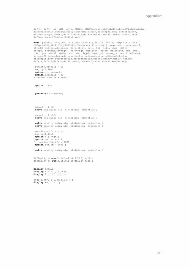
Appendices
215
defhl, defhv, eb, ddB, objs, SMTHL, SMTHV,const1,defrebKW,defcondKW,defmembdev, defcomp1costyr,defcomp2costyr,defcomp1eleckw,defcomp2eleckw,defrebcostyr, defcondcostyr,const2,defA10,defA20,defA30,defA11,defA21,defA31,defK0,defK1, defKeq,tradeoff,selectivityfixed/; Model penalty /IFF,IFP,ILL,FECOLff,FECOLfp,FECOLll,CONff,CONfp,CONll,ODEff, ODEfp,GROUP_AREA,DIM_PRESSURE,fluxconect,fluxconect2,compconect,compconect2, shfpdef,shfrdef,defpbotm, defprebler, errk, tmb, tmb1, tmbn, defln, defap1, feedeqn,feedeqn2, refluxeqn, deftotrd, defrd, defrefcom, cmb, cmb1, cmbn, phe, defhl, defhv, eb, ddB, objpf, SMTHL_pf, SMTHV_pf,const1,defrebKW, defcondKW,defmembdev,defcomp1costyr,defcomp2costyr,defcomp1eleckw, defcomp2eleckw,defrebcostyr,defcondcostyr,const2,defA10,defA20,defA30, defA11,defA21,defA31,defK0,defK1,tradeoff,selectivityfixed,defKeq/; penalty.optfile = 1; reg.optfile=1; option nlp =conopt; option decimals = 8; * option iterlim = 6000; option r:8; parameter toluintop; smooth = 1.e6; solve reg using nlp minimizing objective ; smooth = 1.e12; solve reg using nlp minimizing objective ; solve penalty using nlp minimizing objective ; solve penalty using nlp minimizing objective ; penalty.optfile = 1; reg.optfile=1; option nlp =oqnlp; option decimals = 8; * option iterlim = 3000; option reslim = 3000 ; solve penalty using nlp minimizing objective ; fffinal(j,a)=sum(b,lfinal(b)*ff.l(j,a,b)); fpfinal(j,a)=sum(b,lfinal(b)*fp.l(j,a,b)); Display area.l; Display fffinal,fpfinal; Display ll.l,ff.l,fp.l; keq1(i,j)=y.l(i,j)/x.l(i,j); display keq1, x.l,y.l;
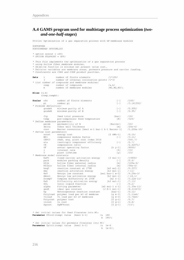
Appendices
216
A.4 GAMS program used for multistage process optimization (two-and-one-half-stages)
$Title: Optimization of a gas separation process with HF-membrane modules $OFFUPPER $OFFSYMXREF OFFSYMLIST * option sysout = off; * OPTION SOLPRINT = OFF; * This file implements the optimization of a gas separation process * using hollow fiber membrane modules. * Objetive function is minimum net present value cost. * Decision variables are membrane areas, permeate pressure and carrier loading. * Constraints are C3H6 and C3H8 product purities. Sets i number of finite elements /1*100/ j number of internal collocation points /1*3/ * List number of compounds and membrane modules: comp number of compounds /a,b/ m number of membrane modules /M1,M2,M3/; Alias (j,k) (comp,compb); Scalar nfe number of finite elements [-] /100/ pi number pi [-] /3.141592/ * Problem definition: gradeA minimum purity of A [-] /0.995/ gradeB minimum purity of B [-] /0.95/ ftp feed total pressure [bar] /18/ temp pre-compressor feed temperature [K] /325/ * Define membrane parameters: permb permeability of B [Barrer] /20/ delta fiber wall thickness [m] /20e-6/ conv Barrer conversion [kmol m-1 bar-1 h-1 Barrer-1] /1.206e-10/ * Define cost parameters: ecost energy cost [$ kWh-1] /0.15/ MFc compressor module factor [-] /3.11/ CEPCI chem. eng. plant cost index 2016 /541.7/ eta isentropic compressor efficiency [-] /0.7/ CR compression ratio /2.62071/ OF annual operating factor [h y-1] /8000/ r interest rate [%] /10/ T plant lifetime [y] /15/ * Membrane model constants EaFC fixed carrier activation energy [J mol-1] /14800/ pack modules packing density [-] /0.6/ Rfib hollow fiber external radius [m] /165e-6/ Rfibin hollow fiber internal radius [m] /90e-6/ keq0 reaction constant at 278K [m3 mol-1] /0.337/ AHr reaction activation energy [kJ mol-1] /-11/ He0 Henrys law constant [mol bar-1 m-3] /4.28e-3/ AHsol Henrys law activation energy [kJ mol-1] /-24.1/ Dcomp0 Complex diffusivity at 293K [m2 s-1] /3.22e-11/ EaD Diffusivity activation energy [kJ mol-1] /7.13/ XIL Ionic liquid fraction [-] /0.2/ alpha Fitting parameter [m2 mol-1 s-1] /1.35e-11/ gasR ideal gas constant [J K-1 mol-1] /8.314472/ kp Heterogeneous reaction constant [bar-1] /0.12/ Polyload polymer load per m3 of membrae [g m-3] /1.11e6/ ILload IL load per m3 of membrane [g m-3] /2.76e5/ Polycost polymer cost [$ g-1] /0.7/ Ilcost IL cost [$ g-1] /0.8/ Agcost AgBF4cost [$ g-1] /13/; * Set initial values for feed flowrates into M1: Parameter ffinit(comp) value [kmol h-1] /a 180 b 180/; * Set initial values for permeate flowrates into M1: Parameter fpinit(comp) value [kmol h-1] /a 1e-6 b 1e-6/;
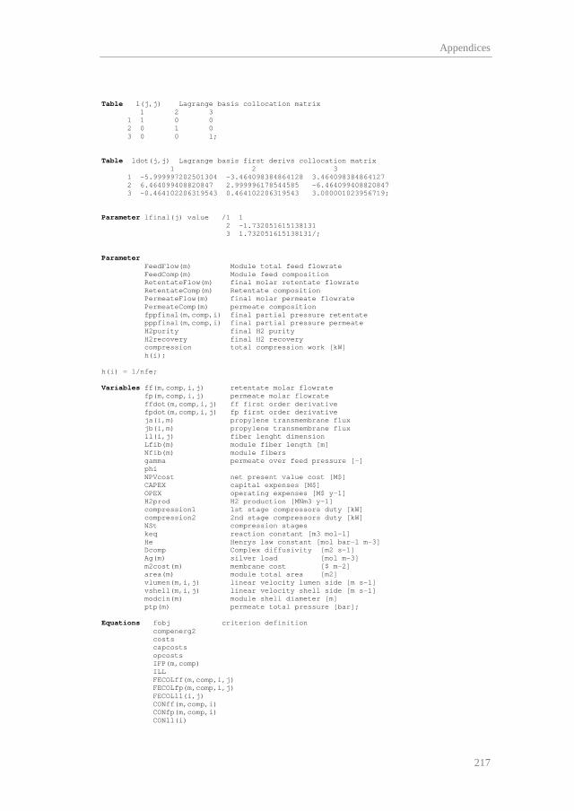
Appendices
217
Table l(j,j) Lagrange basis collocation matrix 1 2 3 1 1 0 0 2 0 1 0 3 0 0 1; Table ldot(j,j) Lagrange basis first derivs collocation matrix 1 2 3 1 -5.999997202501304 -3.464098384864128 3.464098384864127 2 6.464099408820847 2.999996178544585 -6.464099408820847 3 -0.464102206319543 0.464102206319543 3.000001023956719; Parameter lfinal(j) value /1 1 2 -1.732051615138131 3 1.732051615138131/; Parameter FeedFlow(m) Module total feed flowrate FeedComp(m) Module feed composition RetentateFlow(m) final molar retentate flowrate RetentateComp(m) Retentate composition PermeateFlow(m) final molar permeate flowrate PermeateComp(m) permeate composition fppfinal(m,comp,i) final partial pressure retentate pppfinal(m,comp,i) final partial pressure permeate H2purity final H2 purity H2recovery final H2 recovery compression total compression work [kW] h(i); h(i) = 1/nfe; Variables ff(m,comp,i,j) retentate molar flowrate fp(m,comp,i,j) permeate molar flowrate ffdot(m,comp,i,j) ff first order derivative fpdot(m,comp,i,j) fp first order derivative ja(i,m) propylene transmembrane flux jb(i,m) propylene transmembrane flux ll(i,j) fiber lenght dimension Lfib(m) module fiber length [m] Nfib(m) module fibers gamma permeate over feed pressure [-] phi NPVcost net present value cost [M$] CAPEX capital expenses [M$] OPEX operating expenses [M$ y-1] H2prod H2 production [MNm3 y-1] compression1 1st stage compressors duty [kW] compression2 2nd stage compressors duty [kW] NSt compression stages keq reaction constant [m3 mol-1] He Henrys law constant [mol bar-1 m-3] Dcomp Complex diffusivity [m2 s-1] Ag(m) silver load [mol m-3] m2cost(m) membrane cost [$ m-2] area(m) module total area [m2] vlumen(m,i,j) linear velocity lumen side [m s-1] vshell(m,i,j) linear velocity shell side [m s-1] modcin(m) module shell diameter [m] ptp(m) permeate total pressure [bar]; Equations fobj criterion definition compenerg2 costs capcosts opcosts IFP(m,comp) ILL FECOLff(m,comp,i,j) FECOLfp(m,comp,i,j) FECOLll(i,j) CONff(m,comp,i) CONfp(m,comp,i) CONll(i)

Appendices
218
ODEffA(m,i,j) ODEfpA(m,i,j) ODEffB(m,i,j) ODEfpB(m,i,j) CON12Feed(comp) CON31Feed(comp) CON23Feed(comp) PURITYA PURITYB Henry VantHoff Arrhenius MembCost areadef vlumendef (m,i,j) vshelldef (m,i,j) modcindef(m) equalpressure(m); *------------------------------------------------------------------------------- *OBJECTIVE FUNCTION *------------------------------------------------------------------------------- fobj.. phi=e=NPVcost; costs.. NPVcost=e=CAPEX+OPEX*(1-(1+r/100)**(-T))/(r/100); capcosts.. CAPEX=e=sum(m,m2cost(m)*2*pi*Rfib*Nfib(m)*Lfib(m))/10**6+ 23000*((compression2/Nst/74.57)**0.77)* Nst*MFc*(CEPCI/115)/10**6; opcosts.. OPEX=e=compression2*OF*ecost/10**6+ 0.01*sum(m,m2cost(m)*2*pi*Rfib*Nfib(m)*Lfib(m))/10**6; compenerg2.. compression2=e=(sum(j,lfinal(j)*sum(compb,fp('M1',compb,'100',j)))+sum(j,lfinal(j)*sum(compb,fp('M3',compb,'100',j)))) *NSt*(1.15/0.15)*(8.314e-2*temp)*(((ftp/ptp('M1'))**(0.15/1.15/NSt))-1)/ eta/36; MembCost(m).. m2cost(m)-delta*(Polyload*Polycost+ILload*ILcost+Ag(m)*194.67*Agcost)=e=0; areadef(m).. area(m)-2*pi*Rfib*Nfib(m)*Lfib(m)=e=0; *------------------------------------------------------------------------------- * HF-MEMBRANE MODULE EQUATIONS *------------------------------------------------------------------------------- Henry.. He-He0*exp(-AHsol*1000/gasR/temp)=e=0; VantHoff.. Keq-Keq0*exp(-AHr*1000/gasR*(1/temp-1/278))=e=0; Arrhenius.. Dcomp-Dcomp0*exp(-EaD*1000/gasR*(1/temp-1/293))=e=0; *LAGRANGE BASIS COLLOCATION FECOLff(m,comp,i,j)$(ord(j) gt 1).. h(i)*ffdot(m,comp,i,j) =e= sum(k,ldot(k,j)*ff(m,comp,i,k)); FECOLfp(m,comp,i,j)$(ord(j) gt 1).. h(i)*fpdot(m,comp,i,j) =e= sum(k,ldot(k,j)*fp(m,comp,i,k)); FECOLll(i,j)$(ord(j) gt 1).. h(i) =e= sum(k,ldot(k,j)*ll(i,k)); *CONTINUITY ECUATIONS CONff(m,comp,i)$(ord(i) gt 1).. ff(m,comp,i,'1') =e= sum(j, ff(m,comp,i-1,j)*lfinal(j)); CONfp(m,comp,i)$(ord(i) gt 1).. fp(m,comp,i,'1') =e= sum(j, fp(m,comp,i-1,j)*lfinal(j)); CONll(i)$(ord(i) gt 1).. ll(i,'1') =e= sum(j, ll(i-1,j)*lfinal(j)); *ORDINARY DIFFERENTIAL EQUATIONS ODEffA(m,i,j)$(ord(j) gt 1).. ffdot(m,'a',i,j)=e=-2*pi*Lfib(m)*Nfib(m)*Rfib/delta* (ff(m,'a',i,j)/(sum(compb,ff(m,compb,i,j)))*ftp-fp(m,'a',i,j)/(sum(compb,fp(m,compb,i,j)))*ptp(m))* ((keq*Ag(m)*He*Dcomp*XIL/(1+keq*ff(m,'a',i,j)/(sum(compb,ff(m,compb,i,j)))*ftp*He))+ (alpha*exp(EaFC/gasR*(1/293-1/temp))*(Ag(m)/(1+kp*ff(m,'a',i,j)/(sum(compb,ff(m,compb,i,j)))*ftp))*(1-XIL)))*3.6;

Appendices
219
ODEffB(m,i,j)$(ord(j) gt 1).. ffdot(m,'b',i,j)=e=-2*pi*Lfib(m)*Nfib(m)*Rfib/delta* Permb*conv*(ff(m,'b',i,j)/(sum(compb,ff(m,compb,i,j)))*ftp-fp(m,'b',i,j)/(sum(compb,fp(m,compb,i,j)))*ptp(m)); ODEfpA(m,i,j)$(ord(j) gt 1).. fpdot(m,'a',i,j)=e=2*pi*Lfib(m)*Nfib(m)*Rfib/delta* (ff(m,'a',i,j)/(sum(compb,ff(m,compb,i,j)))*ftp-fp(m,'a',i,j)/(sum(compb,fp(m,compb,i,j)))*ptp(m))* ((keq*Ag(m)*He*Dcomp*XIL/(1+keq*ff(m,'a',i,j)/(sum(compb,ff(m,compb,i,j)))*ftp*He))+ (alpha*exp(EaFC/gasR*(1/293-1/temp))*(Ag(m)/(1+kp*ff(m,'a',i,j)/(sum(compb,ff(m,compb,i,j)))*ftp))*(1-XIL)))*3.6; ODEfpB(m,i,j)$(ord(j) gt 1).. fpdot(m,'b',i,j)=e=2*pi*Lfib(m)*Nfib(m)*Rfib/delta* Permb*conv*(ff(m,'b',i,j)/(sum(compb,ff(m,compb,i,j)))*ftp-fp(m,'b',i,j)/(sum(compb,fp(m,compb,i,j)))*ptp(m)); *------------------------------------------------------------------------------- *FLUID DYNAMICS *------------------------------------------------------------------------------- modcindef(m).. modcin(m)-2*rfib*(nfib(m)/pack)**0.5=e=0; vlumendef(m,i,j).. vlumen(m,i,j)-(sum(comp,fp(m,comp,i,j))*gasR*(1e-2)*temp/ptp(m))/Nfib(m)/(pi*rfibin**2)/3600=e=0; vshelldef(m,i,j).. vshell(m,i,j)-(sum(comp,ff(m,comp,i,j))*gasR*(1e-2)*temp/ftp)/(pi*(modcin(m)/2)**2-nfib(m)*pi*rfib**2)/3600=e=0; *------------------------------------------------------------------------------- *CONNECTIONS BETWEEN MEMBRANE MODULES *------------------------------------------------------------------------------- CON12Feed(comp).. ff('M2',comp,'1','1')- fp('M1',comp,'100','3')-fp('M3',comp,'100','3')=e=0; CON31Feed(comp).. ff('M1',comp,'1','1')- ff('M3',comp,'100','3')-ffinit(comp)=e=0; CON23Feed(comp).. ff('M3',comp,'1','1')- ff('M2',comp,'100','3')=e=0; *------------------------------------------------------------------------------- * PROCESS CONSTRAINTS *------------------------------------------------------------------------------- PURITYA.. fp('M2','a','100','3')=g=gradeA* sum(compb,fp('M2',compb,'100','3')); PURITYB.. ff('M1','b','100','3')=g=gradeB* sum(compb,ff('M1',compb,'100','3')); Equalpressure(m).. ptp('M1')-ptp('M3')=e=0; *------------------------------------------------------------------------------- *INITIAL CONDITIONS *------------------------------------------------------------------------------- IFP(m,comp).. fp(m,comp,'1','1')=e=fpinit(comp); ILL.. ll('1','1')=e=0; Model Membrane_module /all/; *------------------------------------------------------------------------------- *VARIABLE LIMITS AND INITIAL GUESSES *------------------------------------------------------------------------------- ff.lo(m,comp,i,j)=0; fp.lo(m,comp,i,j)=1e-6; ff.l(m,comp,i,j)=ffinit(comp); fp.l(m,comp,i,j)=1; ffdot.l(m,comp,i,j)=1; fpdot.l(m,comp,i,j)=1; Lfib.lo(m)=0.1; Lfib.up(m)=4; Lfib.l(m)=1; Nfib.lo(m)=1e3;

Appendices
220
Nfib.up(m)=5e6; Nfib.l(m)=1e5; He.l=61.1; Keq.l=0.337; Dcomp.l=4e-11; NSt.fx = 3; Ag.lo(m)=0; Ag.up(m)=6000; ptp.lo(m)=1; ptp.up(m)=15; *Option nlp=conopt; Membrane_module.optfile=1; Option iterlim=3000; Option reslim=3000; Option nlp=oqnlp; option decimals = 8; Solve Membrane_module minimizing phi using nlp; RetentateFlow(m)=sum(comp,ff.l(m,comp,'100','3')); RetentateComp(m)=ff.l(m,'a','100','3')/sum(comp,ff.l(m,comp,'100','3')); PermeateFlow(m)=sum(comp,fp.l(m,comp,'100','3')); PermeateComp(m)=fp.l(m,'a','100','3')/sum(comp,fp.l(m,comp,'100','3')); FeedFlow(m)=sum(comp,ff.l(m,comp,'1','1')); FeedComp(m)=ff.l(m,'a','1','1')/sum(comp,ff.l(m,comp,'1','1')); jb.l(i,m)=Permb*conv*(ff.l(m,'b',i,'3')/(sum(compb,ff.l(m,compb,i,'3')))*ftp -fp.l(m,'b',i,'3')/(sum(compb,fp.l(m,compb,i,'3')))*ptp.l(m))/delta*1000/3600; ja.l(i,m)=(ff.l(m,'a',i,'3')/(sum(compb,ff.l(m,compb,i,'3')))*ftp- fp.l(m,'a',i,'3')/(sum(compb,fp.l(m,compb,i,'3')))*ptp.l(m))* ((keq.l*Ag.l(m)*He.l*Dcomp.l*XIL/(1+keq.l*ff.l(m,'a',i,'3')/ (sum(compb,ff.l(m,compb,i,'3')))*ftp*He.l))+(alpha*(Ag.l(m)/ (1+kp*ff.l(m,'a',i,'3')/(sum(compb,ff.l(m,compb,i,'3')))*ftp))*(1-XIL)))/delta; Display FeedFlow,FeedComp,RetentateFlow,RetentateComp,PermeateFlow,PermeateComp; Display ll.l,ff.l,fp.l; Display 'Ja in mol/m2/s',ja.l; Display 'Jb in mol/m2/s',jb.l; $ontext $offtext

Agradecimientos
Sirvan estas líneas para mostrar mi más sincero agradecimiento a mis
directores de tesis, la profesora Inmaculada Ortiz y el doctor Alfredo
Ortiz, por haberme dado la oportunidad de desarrollar mi labor
investigadora en el Departamento de Ingenierías Química y Biomolecular
y por haberme guiado durante estos años mostrándome su apoyo y
confianza.
Al profesor Daniel Gorri por haberme prestado sus conocimientos
siempre que los he necesitado, lo que ha constituido una inestimable ayuda
durante el desarrollo de esta tesis.
I would also like to offer special thanks to Prof. Larry Biegler and
Prof. Chung Tai-Shung for accepting me as visiting researcher in their
respective departments, which undoubtedly has contributed to enrich this
PhD thesis.
Por último, a mi familia, especialmente a mis padres, a los
compañeros y compañeras del departamento y a mis amigos y amigas.