Design and Implementation of an Autonomous Driving System ...
71
Final Master Project Master in Automotive Engineering Design and Implementation of an Autonomous Driving System for a RC Car REPORT • Author: Cristian Alonso Vallejo • Director: Juan Manuel Moreno Eguilaz • Call: June 2018 Escola Tècnica Superior d’Enginyeria Industrial de Barcelona
-
Upload
khangminh22 -
Category
Documents
-
view
6 -
download
0
Transcript of Design and Implementation of an Autonomous Driving System ...
Final Master Project
Master in Automotive Engineering
Design and Implementation of an Autonomous
Driving System for a RC Car
REPORT
• Author: Cristian Alonso Vallejo
• Director: Juan Manuel Moreno Eguilaz
• Call: June 2018
Escola Tècnica Superior
d’Enginyeria Industrial de Barcelona

i
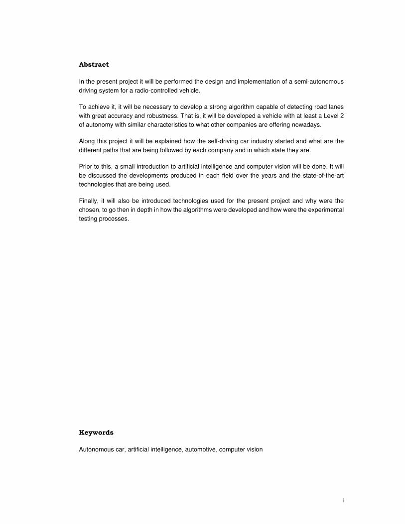
Abstract
In the present project it will be performed the design and implementation of a semi-autonomous
driving system for a radio-controlled vehicle.
To achieve it, it will be necessary to develop a strong algorithm capable of detecting road lanes
with great accuracy and robustness. That is, it will be developed a vehicle with at least a Level 2
of autonomy with similar characteristics to what other companies are offering nowadays.
Along this project it will be explained how the self-driving car industry started and what are the
different paths that are being followed by each company and in which state they are.
Prior to this, a small introduction to artificial intelligence and computer vision will be done. It will
be discussed the developments produced in each field over the years and the state-of-the-art
technologies that are being used.
Finally, it will also be introduced technologies used for the present project and why were the
chosen, to go then in depth in how the algorithms were developed and how were the experimental
testing processes.
Keywords
Autonomous car, artificial intelligence, automotive, computer vision

iii
Table of Contents
1. INTRODUCTION.................................................................................................................... 1
1.1 MOTIVATION ..................................................................................................................... 1
1.2 PROJECT NEEDS ............................................................................................................... 1
1.3 OBJETIVES OF THE PROJECT .............................................................................................. 2
1.4 DESCRIPTIVE MEMORY ...................................................................................................... 2
1.5 PROJECT SCOPE ............................................................................................................... 3
2. STATE OF THE ART ............................................................................................................. 5
2.1 INTRODUCTION .................................................................................................................. 5
2.2 COMPUTER VISION ............................................................................................................ 6
2.3 ARTIFICIAL INTELLIGENCE ................................................................................................ 11
2.4 AUTONOMOUS VEHICLE INDUSTRY ................................................................................... 17
3. HARDWARE ........................................................................................................................ 27
3.1 JETSON TX2 ................................................................................................................... 27
3.2 VEHICLE ......................................................................................................................... 29
3.3 ADAFRUIT PCA9685 ....................................................................................................... 30
4. SOFTWARE ......................................................................................................................... 31
4.1 TECHNOLOGIES ............................................................................................................... 31
4.2 IMPLEMENTATION ............................................................................................................ 35
5. CONCLUSIONS................................................................................................................... 51
6. FUTURE LINES OF RESEARCH........................................................................................ 53
7. ENVIRONMENTAL IMPACT ............................................................................................... 55
8. BIBLIOGRAPHY.................................................................................................................. 57
APPENDIX I. ECONOMIC RECORDS................................................................................. 62
DESIGN AND IMPLEMENTATION OF AN AUTONOMOUS DRIVING SYSTEM FOR A RC CAR
iv
List of Figures
FIGURE 1. ANTHONY REDMILE BODY CHAIR AND WAMHOUSE ZJEDZONY [SOURCE: BEHANCE] ........................................ 6
FIGURE 2. ARCHITECTURE OF LENET-5, A CNN FOR DIGITS RECOGNITION [SOURCE: YANN LECUN] .................................. 7
FIGURE 3. MACHINE INSPECTION EXAMPLE [SOURCE: WIKIPEDIA] .............................................................................. 8
FIGURE 4. POINT CLOUD MODELING OF A BUILDING [SOURCE: FLICKR] ....................................................................... 8
FIGURE 5. MAGNETIC RESONACE IMAGIN (MRI) OF A BRAIN [SOURCE: WIKIPEDIA] ...................................................... 9
FIGURE 6. RENDERED THEME PARK [SOURCE: PIXABAY] .......................................................................................... 10
FIGURE 7. SEMANTIC SEGMENTATION OF A SCENE FROM THE CITYSCAPES DATASET [SOURCE: CITYSCAPES] ...................... 10
FIGURE 8. SCENE COMPLETION ALGORITHM [SOURCE: CARNEGIE MELLON UNIVERSITY] .............................................. 12
FIGURE 9. EVOLUTION OF ALPHAGO ZERO [SOURCE: DEEPMIND] ........................................................................... 14
FIGURE 10. ROOMBA'S CLEANING PATH WITHOUT VISUAL LOCALIZATION [SOURCE: FLICKR] .......................................... 16
FIGURE 11. SAE J3016 SUMMARY TABLE [SOURCE: SAE INTERNATIONAL] ............................................................... 18
FIGURE 12. RECREATION OF A LEVEL 5 AUTONOMOUS VEHICLE [SOURCE: GM] .......................................................... 19
FIGURE 13. CITIES TESTING AND PREPARING FOR THE AUTONOMOUS VEHICLE [SOURCE: BLOOMBERG PHILANTHROPIES] .... 20
FIGURE 14. AN AUTONOMOUS FORD FUSION DRIVING IN MICHIGAN [SOURCE: FORD] ................................................ 21
FIGURE 15. WAYMO 360º EXPERIENCE [SOURCE: YOUTUBE] ................................................................................. 22
FIGURE 16. MICROSOFT AIRSIM [SOURCE: YOUTUBE] ........................................................................................... 23
FIGURE 17. DISTRIBUTION OF ACCIDENTS BY COMPANY IN CALIFORNIA [SOURCE: DMV CA / COMPILED IN-HOUSE] .......... 25
FIGURE 18. CAUSE OF ACCIDENTS BY DRIVING MODE IN CALIFORNIA [SOURCE: DMV CA / COMPILED IN-HOUSE] ............. 26
FIGURE 19. NVIDIA JETSON TX2 MODULE [SOURCE: NVIDIA].............................................................................. 27
FIGURE 20. CARISMA M40S FRAME [SOURCE: CARISMA] ...................................................................................... 29
FIGURE 21. ADAFRUIT PCA9685 CONTROLLER [SOURCE: ADAFRUIT] ....................................................................... 30
FIGURE 22. OPENCV LOGO [SOURCE: WIKIPEDIA] ................................................................................................ 31
FIGURE 23. TENSORFLOW LOGO [SOURCE: WIKIPEDIA] ......................................................................................... 32
FIGURE 24. I2C EXAMPLE WITH TWO CHANNELS [SOURCE: TEXAS INSTRUMENTS] ....................................................... 34
FIGURE 25. I2C COMPLETE DATA TRANSFER [SOURCE: NXP SEMICONDUCTORS] ......................................................... 34
FIGURE 26. ORIGINAL AND GRAYSCALE IMAGE [SOURCE: WIKIPEDIA / COMPILED IN-HOUSE] ........................................ 35
FIGURE 27. GAUSSIAN FILTER [SOURCE: COMPILED IN-HOUSE]................................................................................ 35
FIGURE 28. �� AND �� [SOURCE: COMPILED IN-HOUSE] ...................................................................................... 36
FIGURE 29. GRADIENT MAGNITUDE OUTPUT [SOURCE: COMPILED IN-HOUSE]............................................................ 36
FIGURE 30. INTERPOLATION [SOURCE: D. FORSYTH].............................................................................................. 37
FIGURE 31. NON-MAXIMUM SUPPRESSION [SOURCE: COMPILED IN-HOUSE] .............................................................. 37
FIGURE 32. DOUBLE THRESHOLD [SOURCE: COMPILED IN-HOUSE] ........................................................................... 38
FIGURE 33. FINAL OUTPUT OF THE CANNY EDGE DETECTOR [SOURCE: COMPILED IN-HOUSE] ........................................ 38
FIGURE 34. INPUT IMAGES FROM THE VEHICLE [SOURCE: COMPILED IN-HOUSE] .......................................................... 39
FIGURE 35. OUTPUT OF THE CANNY EDGE DETECTOR IN THE VEHICLE [SOURCE: COMPILED IN-HOUSE] ........................... 39
FIGURE 36. TRANSFORMATION FROM THE ORIGINAL SPACE TO THE �, � HOUGH SPACE [SOURCE: ALYSSA QUEK] ............ 40
FIGURE 37. TRANSFORMATION FROM THE ORIGINAL SPACE TO THE �, � HOUGH SPACE [SOURCE: ALYSSA QUEK] ............. 41
FIGURE 38. RAW OUTPUT OF THE HOUGH TRANSFORM ALGORITHM [SOURCE: COMPILED IN-HOUSE] ............................. 41
FIGURE 39. DETECTED LANES [SOURCE: COMPILED IN-HOUSE] ................................................................................ 42
FIGURE 40. PID ERROR REPRESENTATION [SOURCE: CALTECH] ................................................................................ 43
FIGURE 41. CONVENTIONAL FEEDBACK CONTROL SYSTEM [SOURCE: ARAKI M.] .......................................................... 44
DESIGN AND IMPLEMENTATION OF AN AUTONOMOUS DRIVING SYSTEM FOR A RC CAR
v
FIGURE 42. PID CONTROLLER OUTPUT WITH � = �. � [SOURCE: COMPILED IN-HOUSE].......................................... 44
FIGURE 43. INPUT IMAGE CAPTURED ON THE SECOND 8.472 [SOURCE: COMPILED IN-HOUSE] ...................................... 45
FIGURE 44. TEST TRACK [SOURCE: COMPILED IN-HOUSE] ....................................................................................... 45
FIGURE 45. PID OUTPUT WITH � SET TO 0.5 [SOURCE: COMPILED IN-HOUSE] ......................................................... 46
FIGURE 46. PID OUTPUT WITH � SET TO 0.8 [SOURCE: COMPILED IN-HOUSE] ......................................................... 46
FIGURE 47. EXAMPLE IMAGE OF THE COCO DATASET [SOURCE: COCO] .................................................................. 47
FIGURE 48. TENSORFLOW OBJECT DETECTION API [SOURCE: FLICKR / COMPILED IN-HOUSE] ....................................... 48
FIGURE 49. HAAR FEATURES [SOURCE: OPENCV] ................................................................................................. 48
FIGURE 50. PEOPLE DETECTION [SOURCE: PEXELS / COMPILED IN-HOUSE] ................................................................ 49
FIGURE 51. CAR DETECTION [SOURCE: FLICKR / COMPILED IN-HOUSE] ...................................................................... 50
List of Tables
TABLE 1. AUTONOMOUS VEHICLE DISENGAGEMENT REPORTS 2017 [SOURCE: DMV CA] ........................................... 25
TABLE 2. CAUSE BY ACCIDENTS AND CONTRIBUTING FACTORS CALIFORNIA [SOURCE: DMV CA / COMPILED IN-HOUSE] ..... 26
TABLE 3. JETSON TX2 AND RASPBERRYPI3 CHARACTERISTICS [SOURCE: NVIDIA & RASPBERRYPI] ................................ 28
TABLE 4. CARISMA M40S SPECIFICATIONS [SOURCE: CARISMA] .............................................................................. 29
TABLE 5. ADAFRUIT PCA9685 SPECIFICATIONS [SOURCE: ADAFRUIT] ...................................................................... 30
TABLE 6. COCO DATASET EXAMPLE CAPTION [SOURCE: COCO] .............................................................................. 47

DESIGN AND IMPLEMENTATION OF AN AUTONOMOUS DRIVING SYSTEM FOR A RC CAR
1
1. INTRODUCTION
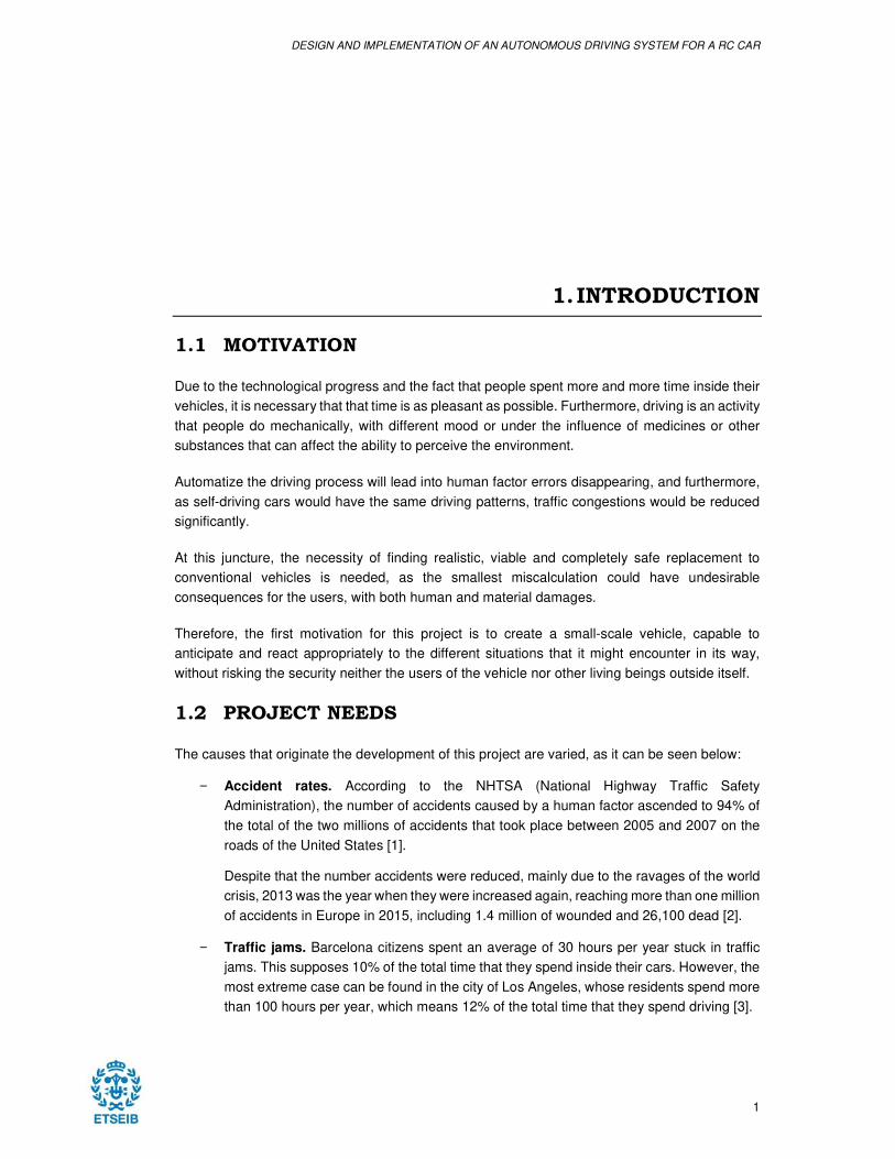
1.1 MOTIVATION
Due to the technological progress and the fact that people spent more and more time inside their
vehicles, it is necessary that that time is as pleasant as possible. Furthermore, driving is an activity
that people do mechanically, with different mood or under the influence of medicines or other
substances that can affect the ability to perceive the environment.
Automatize the driving process will lead into human factor errors disappearing, and furthermore,
as self-driving cars would have the same driving patterns, traffic congestions would be reduced
significantly.
At this juncture, the necessity of finding realistic, viable and completely safe replacement to
conventional vehicles is needed, as the smallest miscalculation could have undesirable
consequences for the users, with both human and material damages.
Therefore, the first motivation for this project is to create a small-scale vehicle, capable to
anticipate and react appropriately to the different situations that it might encounter in its way,
without risking the security neither the users of the vehicle nor other living beings outside itself.
1.2 PROJECT NEEDS
The causes that originate the development of this project are varied, as it can be seen below:
− Accident rates. According to the NHTSA (National Highway Traffic Safety
Administration), the number of accidents caused by a human factor ascended to 94% of
the total of the two millions of accidents that took place between 2005 and 2007 on the
roads of the United States [1].
Despite that the number accidents were reduced, mainly due to the ravages of the world
crisis, 2013 was the year when they were increased again, reaching more than one million
of accidents in Europe in 2015, including 1.4 million of wounded and 26,100 dead [2].
− Traffic jams. Barcelona citizens spent an average of 30 hours per year stuck in traffic
jams. This supposes 10% of the total time that they spend inside their cars. However, the
most extreme case can be found in the city of Los Angeles, whose residents spend more
than 100 hours per year, which means 12% of the total time that they spend driving [3].
DESIGN AND IMPLEMENTATION OF AN AUTONOMOUS DRIVING SYSTEM FOR A RC CAR
2
As Yuki Sugiyama’s study showed in the New Journal of Physics [4], even driving in
circles at a supposedly constant speed, the human being is capable of starting a traffic
jam due to distractions, poor sensitivity of the gas pedal, getting closer to the preceding
car and unnecessarily stepping on the brakes afterwards, etc.
On the contrary, computer equipment can be adapted to precedent vehicle speeds very
accurately without aggressive changes of speed, even anticipating to some events due
to self-driving cars sharing information between them.
− Efficiency. Each person drives totally different. Each type of engine, using either
gasoline, diesel oil or electricity has a different maximum efficiency point, and people
does not normally reach this point, due to both lack of awareness and the difficulty to
calculate it.
However, a powerful enough microprocessor would be able to calculate precisely that
point, and besides, be ready for the different necessities that the engine might require for
the next operation.
− Pollution. The last two points lead us directly towards this one. If cars were driven more
efficiently and less time was spent inside them, the emission of harmful gases would be
less harmful for the environment when it came to combustion cars. In addition, the
number of charges for electric vehicles would be reduced too, causing the electricity
generation to be reduced.
1.3 OBJETIVES OF THE PROJECT
The main goals that are expected to be reached in this project are the following:
1. Design and implement of an autonomous system able to follow the path of the road
through which it circulates, being capable of recognize and adapt to the different traffic
signals it encounters in its way.
2. Program efficiently the detection algorithms so that memory consumption would be as
low as possible and its precision could be high enough to avoid what could be accidents
in real life.
3. Design and assembly the required structures and frames to mount all the different
components and devices used in the project.
1.4 DESCRIPTIVE MEMORY
The present project will require to present the self-driving car in the specified date. In order to do
this, a scales radio-controlled car would be the base used to install an embedded system capable
of accomplishing the driving tasks autonomously. Hereafter, the project can be divided in clearly
different tasks:
− In the first place, autonomous vehicles will be studied, both the ones that are already
being sold and the ones that are being developed. The type of technology used by each
DESIGN AND IMPLEMENTATION OF AN AUTONOMOUS DRIVING SYSTEM FOR A RC CAR
3
one and their level of autonomy will also be discussed, including the benefits and
disadvantages of each one of them.
− Afterwards, the acquisition, adjustments and assembly of each component will take place
once the technology that is going to be used in the project is selected based on the budget
and the performance offered by each component.
− Finally, the used systems will be programed individually in the first place to reach the
maximum performance of each algorithm. When tasks are finished, different algorithms
will be joined and put to work together.
1.5 PROJECT SCOPE
It must be considered that the intention of this project is only to design a scale prototype capable
of working with a minimum level of autonomy and that fulfills all the goals stated in the first section
of the document.
The project is started with the structure of a 1/10 scale radio-controlled car with electric propulsion
system controlled by pulse width modulation (PWM) signal, chosen by its great similarity with
conventional vehicles as it has suspension and steering systems really close to their real versions.
The road recognition system for the vehicle will be determined in the first place by a high definition
camera mounted in the front part of the vehicle, placed at what it would be the hood of the car
The image captured by the camera will be cloned and processed in parallel. One of the threads,
and also the main one, will be used to detect road lanes. The other one will be used to process
the surroundings for detecting and identifying whether there are cars or people in the vehicle’s
surroundings.
One of the most important points of the project is the lane detection algorithm, as even though
the system will only be tested in a simulated environment, the road conditions or the weather
could generate false positives leading into a hazardous situation for the users of the vehicle or
the pedestrians.
Having said this, the project is divided in the following tasks:
− Study, design and implementation of the lane detection algorithm.
− Design, implementation and programing of the control system for the electric motors.
− Study and design of the car and people detection algorithm.
− Combine all the algorithms to work altogether.

DESIGN AND IMPLEMENTATION OF AN AUTONOMOUS DRIVING SYSTEM FOR A RC CAR
5
2. STATE OF THE ART
2.1 INTRODUCTION
The second edition of the DARPA Grand Challenge took place in 2005. This annual competition
consisted in a long-distance race with a two million dollars prize for the winner, in which its
participants could only be autonomous vehicles. The event was organized by the Defense
Advanced Research Project Agency, the Research and Development agency of the Defense
Department of the United States.
The main goal of the competition was to encourage the collaboration of experts on many diverse
technological fields from both private companies and academic institutions to get them to improve
the technology by sharing information between them [5].
March 13, 2004 was the first edition of the competition in which 15 teams participated on the
desert of Barstow, California, to cover a distance of 142 miles (228.5 km) in less than 10 hours
for half the prize of the following year, one million dollars. Nevertheless, none of teams were able
to finish the race and the longest distance covered by them was only 7.5 miles (12 km), so the
prize was not awarded.
Despite the bad results achieved that year, the feeling was very positive for the organization, as
well as for the participants, so the following morning it was announced by DARPA that the next
edition would be held 18 months later, October 10, 2005.
The following year had 195 vehicles enrolled, of which 23 were classified for the main event.
Finally, the route was only covered by five of the cars and the winner was the Volkswagen
Touareg from the University of Stanford, which was named “Stanley”, which covered the distance
in 6 hours and 53 minutes. Sebastian Thrun, co-inventor of Google Street View and later creator
of its self-driving car team, was the leader of the team [6].
That was probably the year that made the difference into making the industry and investigation
centers getting involved, but self-driving cars had been tested for many more years before the
DARPA competition was held. As an example, the Project Eureka Prometheus, which started in
1987 and involved many companies from the automotive industry, was founded with 749 million
euros [7].
DESIGN AND IMPLEMENTATION OF AN AUTONOMOUS DRIVING SYSTEM FOR A RC CAR
6
2.2 COMPUTER VISION
2.2.1 State of the art
The world is perceived by the human being in three dimensions without any difficulty. Humans
can differentiate the shape of the objects or their translucency through the patterns of light and
shadows that cross their surface without being influenced of the background, for example. They
can differentiate the number of people that appear in a picture, their genders, names, guess the
age or even their mood by their facial expressions or gestures.
New techniques to recover the tridimensional shape and appearance of the taken images have
been tried to be developed by computer vision investigators during the latest years. In fact, a
three-dimensional model of an element can be obtained by overlapping hundreds of photographs
from different perspectives, and a person in movement can be detected, followed and even
identified through a background with different colors or depths.
However, even though with these technological advances, it is very complicated for a computer
to interpret an image as a small child would do it. A good example of this would be to discover
what a cat or a dog is without having fed an algorithm with thousands of images of different
breeds, colors or sizes of said animals.
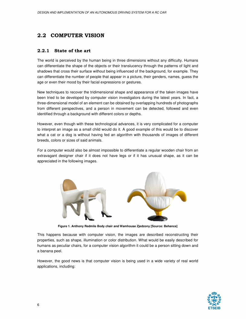
For a computer would also be almost impossible to differentiate a regular wooden chair from an
extravagant designer chair if it does not have legs or if it has unusual shape, as it can be
appreciated in the following images.
Figure 1. Anthony Redmile Body chair and Wamhouse Zjedzony [Source: Behance]
This happens because with computer vision, the images are described reconstructing their
properties, such as shape, illumination or color distribution. What would be easily described for
humans as peculiar chairs, for a computer vision algorithm it could be a person sitting down and
a banana peel.
However, the good news is that computer vision is being used in a wide variety of real world
applications, including:
DESIGN AND IMPLEMENTATION OF AN AUTONOMOUS DRIVING SYSTEM FOR A RC CAR
7
2.2.1.1 Optical character recognition (OCR).
Optical character recognition is the conversion of images of typed, handwritten or printed text into
machine-encoded text. It is used as an information entry from printed paper data records such as
passport documents, invoices, mail information, invoices, or any suitable documentation so that
the information that contains can be edited, searched or used in other processes such as text-to-
speech, translations, text mining…
Optical character recognition can be used for:
− Automatic number plate recognition.
− Reading handwritten addresses on letters.
− Make text version of printed documents or books (i.e. Project Gutenberg or Google
Books).
− Converting handwriting in real time to control a computer.
− Assistive technology for blind and visually impaired users.
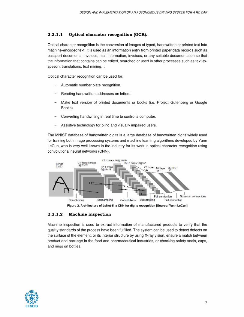
The MNIST database of handwritten digits is a large database of handwritten digits widely used
for training both image processing systems and machine learning algorithms developed by Yann
LeCun, who is very well known in the industry for its work in optical character recognition using
convolutional neural networks (CNN).
Figure 2. Architecture of LeNet-5, a CNN for digits recognition [Source: Yann LeCun]
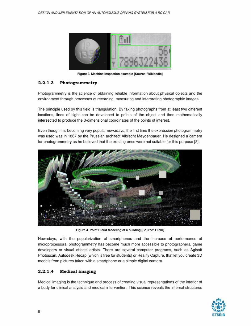
2.2.1.2 Machine inspection
Machine inspection is used to extract information of manufactured products to verify that the
quality standards of the process have been fulfilled. The system can be used to detect defects on
the surface of the element, or its interior structure by using X-ray vision, ensure a match between
product and package in the food and pharmaceutical industries, or checking safety seals, caps,
and rings on bottles.
DESIGN AND IMPLEMENTATION OF AN AUTONOMOUS DRIVING SYSTEM FOR A RC CAR
8
Figure 3. Machine inspection example [Source: Wikipedia]
2.2.1.3 Photogrammetry
Photogrammetry is the science of obtaining reliable information about physical objects and the
environment through processes of recording, measuring and interpreting photographic images.
The principle used by this field is triangulation. By taking photographs from at least two different
locations, lines of sight can be developed to points of the object and then mathematically
intersected to produce the 3-dimensional coordinates of the points of interest.
Even though it is becoming very popular nowadays, the first time the expression photogrammetry
was used was in 1867 by the Prussian architect Albrecht Meydenbauer. He designed a camera
for photogrammetry as he believed that the existing ones were not suitable for this purpose [8].
Figure 4. Point Cloud Modeling of a building [Source: Flickr]
Nowadays, with the popularization of smartphones and the increase of performance of
microprocessors, photogrammetry has become much more accessible to photographers, game
developers or visual effects artists. There are several computer programs, such as Agisoft
Photoscan, Autodesk Recap (which is free for students) or Reality Capture, that let you create 3D
models from pictures taken with a smartphone or a simple digital camera.
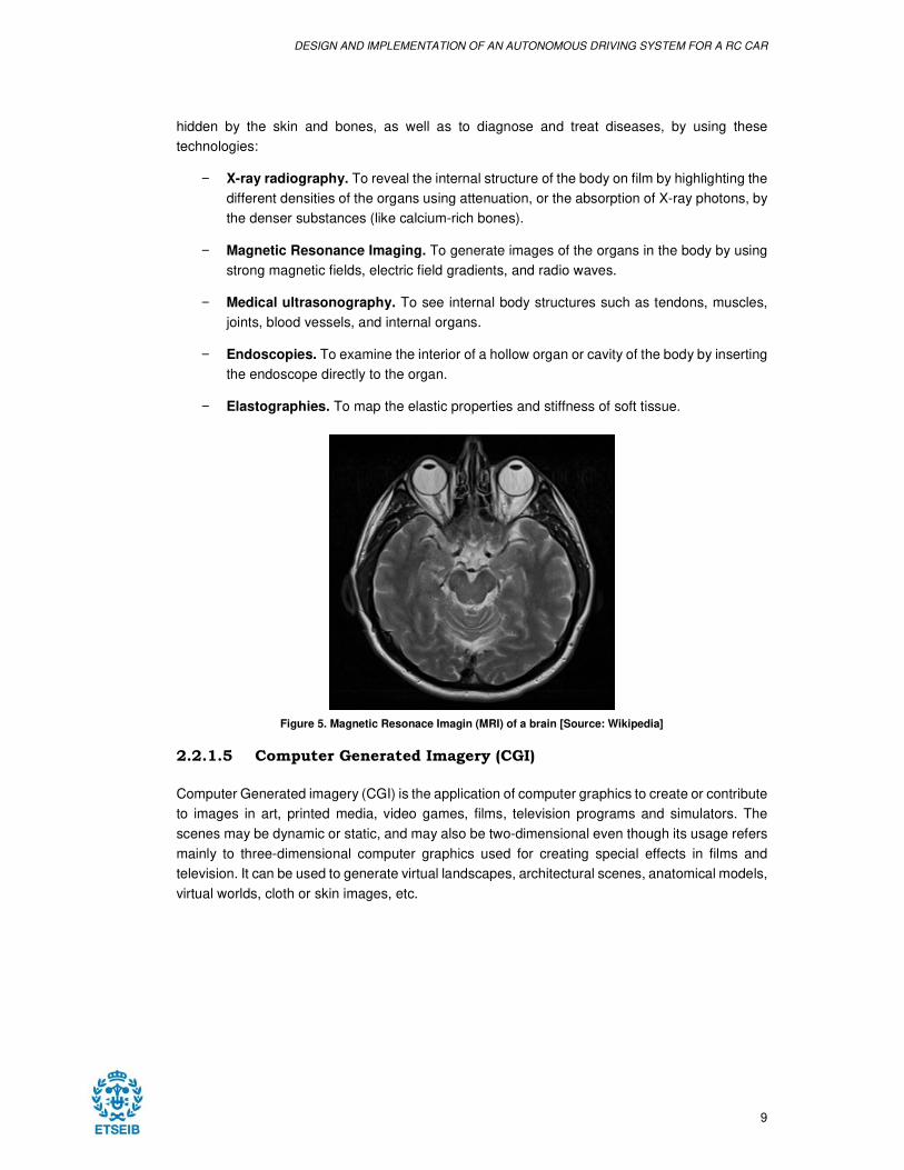
2.2.1.4 Medical imaging
Medical imaging is the technique and process of creating visual representations of the interior of
a body for clinical analysis and medical intervention. This science reveals the internal structures
DESIGN AND IMPLEMENTATION OF AN AUTONOMOUS DRIVING SYSTEM FOR A RC CAR
9
hidden by the skin and bones, as well as to diagnose and treat diseases, by using these
technologies:
− X-ray radiography. To reveal the internal structure of the body on film by highlighting the
different densities of the organs using attenuation, or the absorption of X-ray photons, by
the denser substances (like calcium-rich bones).
− Magnetic Resonance Imaging. To generate images of the organs in the body by using
strong magnetic fields, electric field gradients, and radio waves.
− Medical ultrasonography. To see internal body structures such as tendons, muscles,
joints, blood vessels, and internal organs.
− Endoscopies. To examine the interior of a hollow organ or cavity of the body by inserting
the endoscope directly to the organ.
− Elastographies. To map the elastic properties and stiffness of soft tissue.
Figure 5. Magnetic Resonace Imagin (MRI) of a brain [Source: Wikipedia]
2.2.1.5 Computer Generated Imagery (CGI)
Computer Generated imagery (CGI) is the application of computer graphics to create or contribute
to images in art, printed media, video games, films, television programs and simulators. The
scenes may be dynamic or static, and may also be two-dimensional even though its usage refers
mainly to three-dimensional computer graphics used for creating special effects in films and
television. It can be used to generate virtual landscapes, architectural scenes, anatomical models,
virtual worlds, cloth or skin images, etc.
DESIGN AND IMPLEMENTATION OF AN AUTONOMOUS DRIVING SYSTEM FOR A RC CAR
10
Figure 6. Rendered theme park [Source: Pixabay]
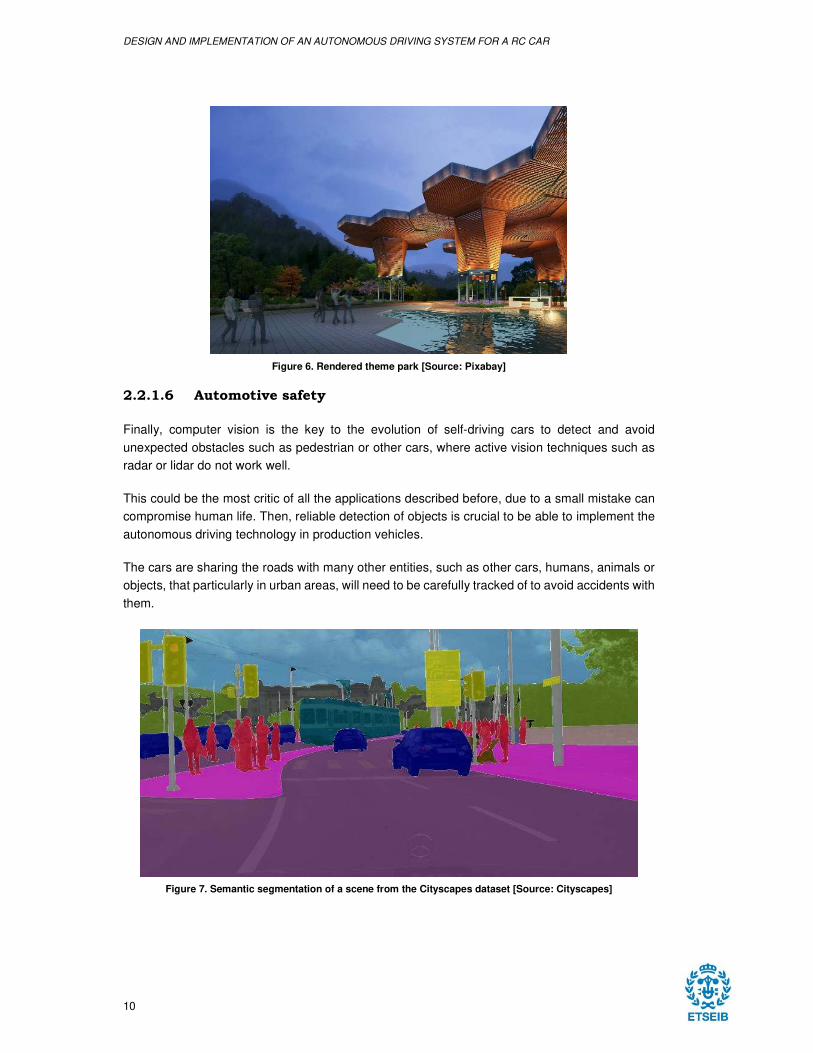
2.2.1.6 Automotive safety
Finally, computer vision is the key to the evolution of self-driving cars to detect and avoid
unexpected obstacles such as pedestrian or other cars, where active vision techniques such as
radar or lidar do not work well.
This could be the most critic of all the applications described before, due to a small mistake can
compromise human life. Then, reliable detection of objects is crucial to be able to implement the
autonomous driving technology in production vehicles.
The cars are sharing the roads with many other entities, such as other cars, humans, animals or
objects, that particularly in urban areas, will need to be carefully tracked of to avoid accidents with
them.
Figure 7. Semantic segmentation of a scene from the Cityscapes dataset [Source: Cityscapes]
DESIGN AND IMPLEMENTATION OF AN AUTONOMOUS DRIVING SYSTEM FOR A RC CAR
11
The availability of large-scale datasets such as ImageNet or Microsoft COCO and the
improvement in the performance of newer computers have brought an enormous increase of
accuracy of machine learning algorithms for object detection.
2.3 ARTIFICIAL INTELLIGENCE
2.3.1 History
2.3.1.1 The early days
Artificial intelligence is the science that attempts to both understand and build intelligent entities.
It is one of the newest and most popular fields in science in engineering, even though that the
first work recognized today as Artificial Intelligence was done by Warren McCulloch and Walter
Pitts in 1943 [9].
They showed that any computable function could be computed by some network of connected
neurons, and that all the logical connectives (and, or, not, etc.) could be implemented by simple
net structure. They also suggested that suitably defined networks could learn.
Alan Turing was giving lectures on the topic in 1947 at the London Mathematical Society and
three years later, in 1950 wrote the article “Computing Machinery and Intelligence”, in which he
introduced the Turing Test, machine learning, genetic algorithms and reinforcement learning.
That same year, two Harvard students, Marvin Minsky and Dean Edmonds, built the first neural
network computer, called the SNARC. It used 3000 vacuum tubes and an automatic pilot
mechanism from a B-24 bomber to simulate a network of 40 neurons.
However, it was not until 1956, in Dartmouth College, that the field was born. John McCarthy
asked Marvin Minsky, Claude Shannon, and Nathaniel Rochester for their help to organize a two-
month workshop in which another six more people participated.
2.3.1.2 The digital era
One of the most important environment for the development of the field was, and is, the Internet.
The Artificial Intelligent agents became so common in Web-based applications. Tools such as
search engines with Google, Bing or Yahoo as an example, or recommender systems with very
different approaches, like Netflix suggesting new different shows that the user may like, or Spotify
and Amazon basing their suggestions only on similar items that the user has already listened to
or bought.
Although in the early days of the Artificial Intelligence investigations the scientists had the thought
that the emphasis should be in the improvement of the algorithm, nowadays, the most recent
investigations suggest that for many problems, it makes more sense to worry about the data and
not the algorithm used. This thinking became more popular as the data available on the Web was
increasing rapidly to numbers as big as billions of images or words of the English language.
DESIGN AND IMPLEMENTATION OF AN AUTONOMOUS DRIVING SYSTEM FOR A RC CAR
12
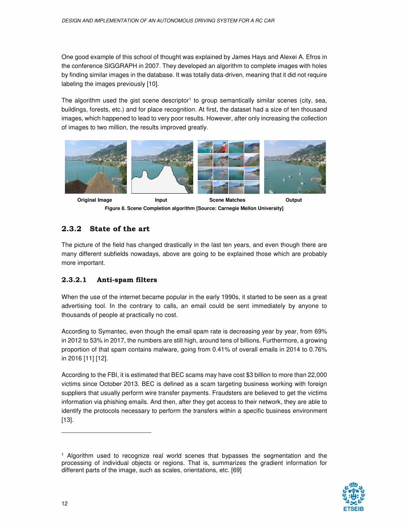
One good example of this school of thought was explained by James Hays and Alexei A. Efros in
the conference SIGGRAPH in 2007. They developed an algorithm to complete images with holes
by finding similar images in the database. It was totally data-driven, meaning that it did not require
labeling the images previously [10].
The algorithm used the gist scene descriptor1 to group semantically similar scenes (city, sea,
buildings, forests, etc.) and for place recognition. At first, the dataset had a size of ten thousand
images, which happened to lead to very poor results. However, after only increasing the collection
of images to two million, the results improved greatly.
Original Image Input Scene Matches Output
Figure 8. Scene Completion algorithm [Source: Carnegie Mellon University]
2.3.2 State of the art
The picture of the field has changed drastically in the last ten years, and even though there are
many different subfields nowadays, above are going to be explained those which are probably
more important.
2.3.2.1 Anti-spam filters
When the use of the internet became popular in the early 1990s, it started to be seen as a great
advertising tool. In the contrary to calls, an email could be sent immediately by anyone to
thousands of people at practically no cost.
According to Symantec, even though the email spam rate is decreasing year by year, from 69%
in 2012 to 53% in 2017, the numbers are still high, around tens of billions. Furthermore, a growing
proportion of that spam contains malware, going from 0.41% of overall emails in 2014 to 0.76%
in 2016 [11] [12].
According to the FBI, it is estimated that BEC scams may have cost $3 billion to more than 22,000
victims since October 2013. BEC is defined as a scam targeting business working with foreign
suppliers that usually perform wire transfer payments. Fraudsters are believed to get the victims
information via phishing emails. And then, after they get access to their network, they are able to
identify the protocols necessary to perform the transfers within a specific business environment
[13].
1 Algorithm used to recognize real world scenes that bypasses the segmentation and the processing of individual objects or regions. That is, summarizes the gradient information for different parts of the image, such as scales, orientations, etc. [69]
DESIGN AND IMPLEMENTATION OF AN AUTONOMOUS DRIVING SYSTEM FOR A RC CAR
13
However, having said this, and even though the spammers are continually updating their tactics,
classifying algorithms have improved their performance so much than users rarely have to identify
their email as spam or even check their spam folder just in case a false positive was sent there
accidentally.
2.3.2.2 Voice assistants
Voice assistants like Alexa, Siri or Google Assistant have become part of everyone’s life in the
last years. From tasks as simple as giving the weather, setting alarms or increase the music
volume to being capable of making a reservation in a restaurant or a hair salon with a noisy
environment [14].
Google has recently announced Google Duplex, a technology for conducting natural
conversations to carry out simple tasks over the phone, such as appointments. Instead of
following a scripted conversation with a robot-like voice, the system adjusts itself to the caller
using a completely natural voice.
The company has developed a deep neural network for generating raw audio waveforms,
WaveNet, that it is able to capture the characteristics of many different English and Mandarin
speakers with equal fidelity and then switch between them depending of the speaker identity.
WaveNet, when trained to model music, can create novel and highly realistic musical fragments
[15] [16].
2.3.2.3 Game playing
Since the beginning of the development of Artificial Intelligence, there has been a willingness for
a computer to compete against humans. Game playing provided a high-visibility platform for this
purpose.
The first game mastered by a computer was tic-tac-toe, in 1952 as a PhD candidate’s project, but
it was not until 1997 when one of these projects gained world media coverage.
IBM’s Deep Blue became the first computer to defeat a world chess champion, Garry Kasparov,
in 1997 after a six-game match. After that event, many people designed different types of
programs and computers for game playing with various degrees of success.
While humans could think about tens or hundreds of positions while considering a move, a
computer, on the other hand, was able to consider billions even at a quicker speed than the
human. As an example, Deep Blue had 480 chess-specific processors, each of which capable of
examining about two million chess positions a second. [17].
More recently, IBM’s Watson won the first place on Jeopardy in 2011 and in 2014, Google’s own
algorithms learned how to play dozens of Atari games just by examining raw pixel inputs. Then,
DESIGN AND IMPLEMENTATION OF AN AUTONOMOUS DRIVING SYSTEM FOR A RC CAR
14
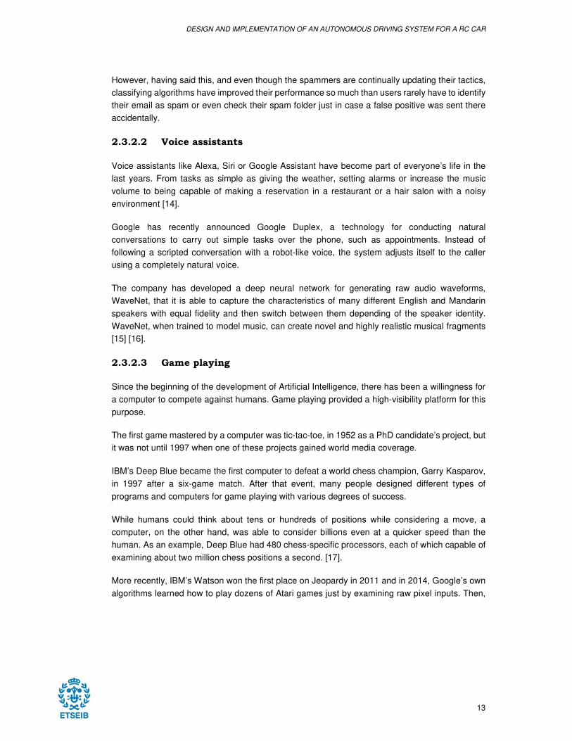
the company also launched AlphaGo, a computer program that plays the board game Go2 and
that became the first one to beat a human professional Go player in 2015 and then next year beat
the 9-dan professional Lee Sedol.
Figure 9. Evolution of AlphaGo Zero [Source: DeepMind]
Now, AlphaGo Zero, instead of being trained playing thousands of games versus amateur and
professional players, it learned by only playing against itself, starting from completely random
play. This version was able to surpass all the previous versions of the system, without human
intervention nor historical data, after 40 days [18] [19].
2.3.2.4 Machine translators
In the latest years, machine translators have evolved from using statistical models to translate
automatically texts phrase by phrase to using neural networks capable of analyzing the text from
the beginning to the end, and thus, being able to understand the context of the entire text after
have being trained with millions of examples.
The Neural Machine Translators are known to be computationally more expensive both in training
and in the act of translation, but recently, Google has designed a new approach to speed up the
process using a Long Short-Term Memory network (LSTM) instead of the previous recurrent
networks [20].
They have also presented in October 2017 their headphones for their new mobile, called Pixel
Buds, capable to translate conversations in real time up to 40 languages. Companies such as
Waberly Labs with their headphones, Travis with their Bluetooth speaker or Fujitsu with their
wearable have also presented their competitors, which can translate 15, 80 and 5 languages
respectively.
2 Go, played by more than 40 million people worldwide, is a board game invented in China more than 2,500 years ago. Despite its simple rules, it is considered one of the most difficult board games
DESIGN AND IMPLEMENTATION OF AN AUTONOMOUS DRIVING SYSTEM FOR A RC CAR
15
However, there is a company that can face Google as it has as many information as them thanks
to the fact that it has been the leader in personal computers since the late 1980s, when the first
version of Windows appeared.
As a matter of fact, apart from their real time translation system for Skype’s videoconferences
launched in October 2015, they announced March 2018 that its researchers in Asia and the United
States have reached human parity on used test set of news called newstest2017 created for a
research conference called WMT17.
The system, that only translates from Chinese to English for now and relies on deep neural
networks, uses a method called dual learning that checks its own work by translating back to the
original language to compare the accuracy achieved. Due to that, the system learns by its
mistakes and refines the subsequent translations [21].
2.3.2.5 Logistic planners
Logistic companies can benefit of Artificial Intelligence in almost all aspects of the supply chain,
due to the high volumes of data that supply chains generate every day.
These companies depend on networks that should function harmoniously with high volumes, low
margins and very strict deadlines. However, the adoption of Artificial Intelligence can help logistics
industry to achieve more precise predictions, more autonomous processes and services
personalized for every different client.
There are many applications that can be benefited from the adoption of Artificial intelligence. One
of them could be to process invoices with a natural language algorithm and extract critical
information such as billing amounts, account information, dates, addresses and parties involved.
Once the data is classified, another intelligent entity would introduce the data into an accounting
software to create an order, execute the payment, and finally send the customer a confirmation
email.
Companies like Ernst & Young are applying a similar solution to detect fraudulent invoices using
machine learning. They classify the invoices and identify anomalies, which are reviewed later by
experts to comply with sanctions, anti-bribery regulations and other corrupt practices. Their
solution achieves 97% of accuracy and was used by over 50 companies in 2017 [22].
Logistic companies also manage large fleets of vehicles, whose planification would take weeks if
it had to be calculated by a team of human experts. As an example, during the Persian Gulf Crisis
in 1991, the U.S. forces deployed a tool to do automated logistic planning and scheduling for
transportation. They generated within hours a solution to move 50,000 vehicles and people at a
time, having into account starting points, destinations and routes. This action could have taken
weeks using older methods.
2.3.2.6 Self-driving vehicles
Autonomous systems are being applied to what until the latest years were objects whose use
could not be imagined without human intervention. From robots used in warehouses and factories
DESIGN AND IMPLEMENTATION OF AN AUTONOMOUS DRIVING SYSTEM FOR A RC CAR
16
to distribute manufacturing parts to vehicles capable of travelling from one place to another by
itself.
Since 1990, the NASA has been developing robotic entities for planetary exploration to perform
work that cannot, or should not, be carried out by humans. Some of that work could be performed
by humans, but many of that work can be done without their intervention.
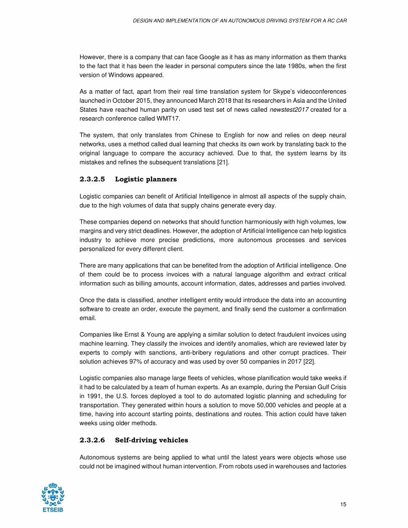
There are also robots that are able to fulfill more mundane tasks without human intervention at
home. iRobot is the creator of Roomba, a vacuuming robot with more than 20 million units sold
since 2002.
Figure 10. Roomba's cleaning path without visual localization [Source: Flickr]
iRobot did not introduce the visual localization nor the mapping navigation system (vSLAM) in
their Roombas. Instead, the company developed algorithms for cleaning in spiral-shape path,
following the walls and changing randomly the angle after bumping into an obstacle.
Automotive companies are probably within the industries that are focusing more in tasks related
to Artificial Intelligence. As it is going to be extended in section 2.4, not only traditional car
manufacturers, but also technological companies such as Google, Amazon or Apple are working
on it.
As stated in section 1.2, the implementation of autonomous car would bring many advantages,
such as more safety on the road, less pollution, less traffic jams and even more welfare as the
insurances, labor costs or car ownership would be lower.
However, the adoption of autonomous vehicles would affect jobs related to driving, such as the
public transport systems or even crash repair shops as the accidents would be reduced. Another
industry affected by the latter would be the insurance companies, whose services offered should
be modified if there are much less accidents.
DESIGN AND IMPLEMENTATION OF AN AUTONOMOUS DRIVING SYSTEM FOR A RC CAR
17
2.3.3 Controversies
Not everything that the Artificial Intelligence is bringing is positive, specially speaking in terms of
privacy. It has already been stated previously that the more data, the better and that is what every
big tech firm is doing right now, they are collecting data indiscriminately from all the services they
offer.
There have been companies, for example, that needed to explain how their voice assistant had
recorded private conversations of a couple and the sent it to one of the user’s contacts without
their knowledge. The same company also suffered from their voice assistant making laugh noises
without the users asking for it [23].
Neil Lawrence, professor of Machine Learning at the University of Sheffield and integrant of
Amazon’s AI team, states that the enormous quantity of data available for the major internet
companies reminds to the early stage of the industrial revolution.
He gives the example of Thomas Newcomen, who invented a steam motor before James Watt
did. The motor was inefficient and costly to run, but it was not a problem for coalfields, where the
fuel was plentiful [24].
This means that having enough data, algorithms does not have to be really efficient, what can
make them vulnerable to adversarial examples. Researchers from several American universities
showed in July 2017 how a state-of-the-art deep neural network can be affected to small
perturbations added to the inputs, such as misclassify road signals by adding small stickers onto
them [25].
Local councils in Great Britain spent over £550 million (€706 million at that time) between 2008
and 2012 installing new cameras around their cities. Despite being one of the most surveilled
cities in the world with thousands of cameras, the crime has barely decreased.
Furthermore, during a sports final in Wales in June 2017, there were 2,470 alerts of matches from
the automated system of which 2,297 turned out to be false positives, meaning that 92% of the
matches were incorrect [26] [27].
2.4 AUTONOMOUS VEHICLE INDUSTRY
Autonomous vehicles use most of the technologies explained before, incorporating also
sometimes other elements that will be explained shortly. Depending on the used hardware and
the involved team developing the autonomous vehicle technology, five different levels can be
achieved according to the NHTSA (National Highway Traffic Safety Administration).
2.4.1 SAE International’s Levels of Driving Automation
SAE International provided what now is very common used way of describing the different levels
of automation of a car. These levels indicate the minimum system capabilities that a car should
have to be in any of the levels [28].
DESIGN AND IMPLEMENTATION OF AN AUTONOMOUS DRIVING SYSTEM FOR A RC CAR
18
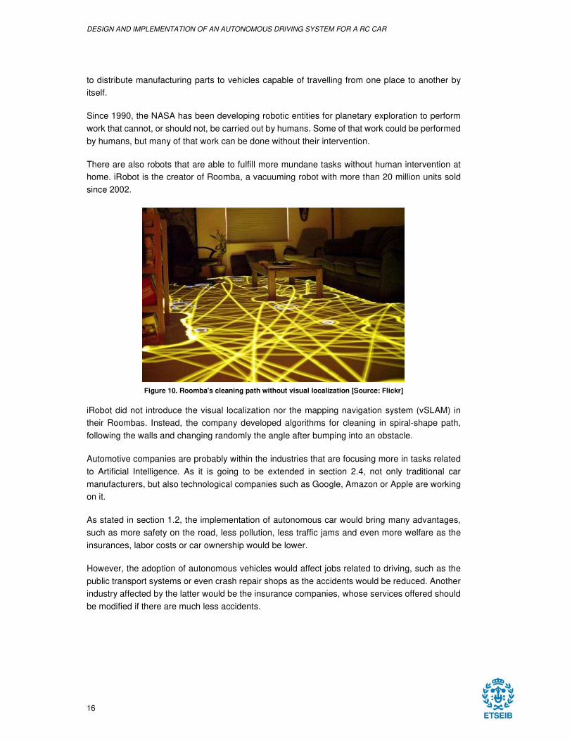
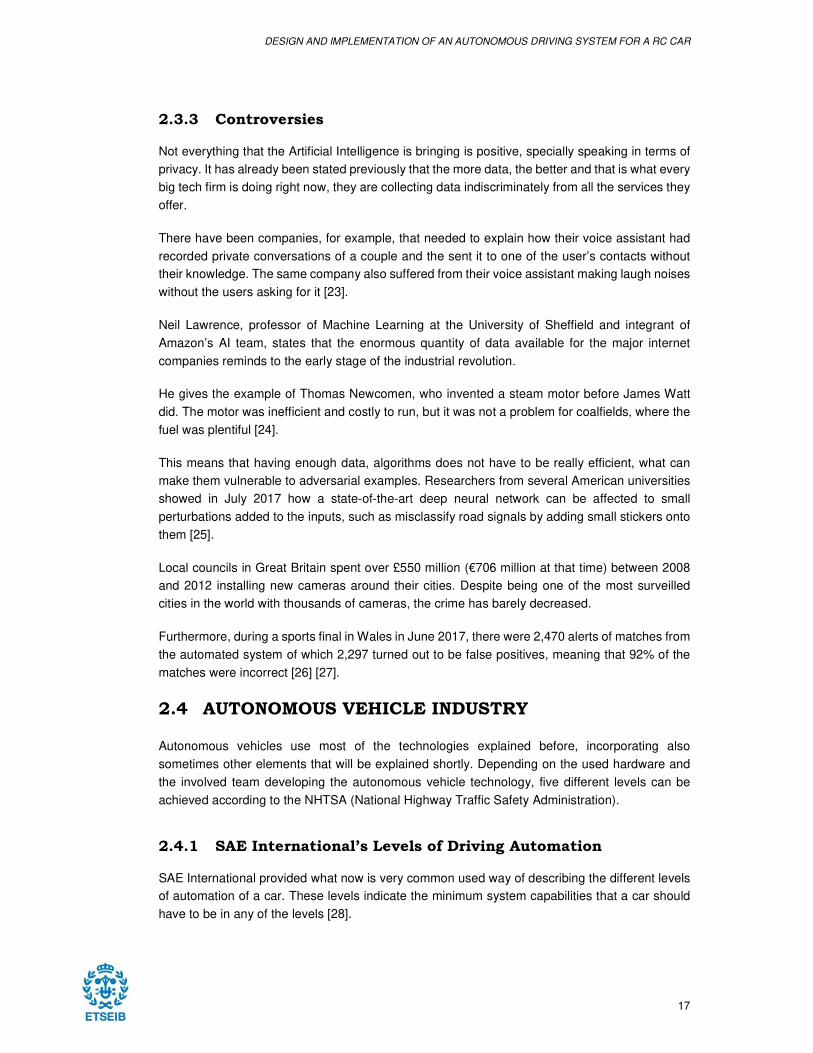
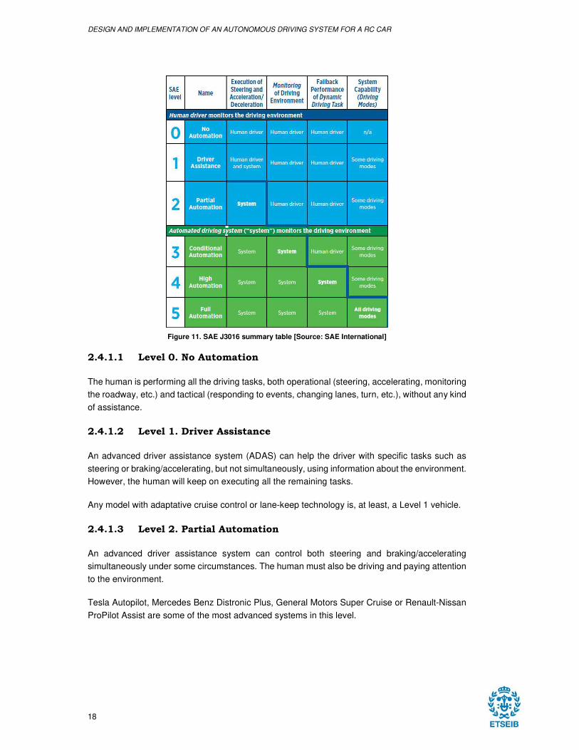
Figure 11. SAE J3016 summary table [Source: SAE International]
2.4.1.1 Level 0. No Automation
The human is performing all the driving tasks, both operational (steering, accelerating, monitoring
the roadway, etc.) and tactical (responding to events, changing lanes, turn, etc.), without any kind
of assistance.
2.4.1.2 Level 1. Driver Assistance
An advanced driver assistance system (ADAS) can help the driver with specific tasks such as
steering or braking/accelerating, but not simultaneously, using information about the environment.
However, the human will keep on executing all the remaining tasks.
Any model with adaptative cruise control or lane-keep technology is, at least, a Level 1 vehicle.
2.4.1.3 Level 2. Partial Automation
An advanced driver assistance system can control both steering and braking/accelerating
simultaneously under some circumstances. The human must also be driving and paying attention
to the environment.
Tesla Autopilot, Mercedes Benz Distronic Plus, General Motors Super Cruise or Renault-Nissan
ProPilot Assist are some of the most advanced systems in this level.
DESIGN AND IMPLEMENTATION OF AN AUTONOMOUS DRIVING SYSTEM FOR A RC CAR
19
2.4.1.4 Level 3. Conditional Automation
An Automated Driving System (ADS) can perform all the aspects of the driving tasks under some
circumstances, while the human should be prepared to take back control when the ADS requires
it.
To this date, there is not any car being sold with this level of autonomy, even though Google
already achieved it in 2012. However, they decided to directly aim for Level 5 cars as they found
drivers sleeping on the car while it was driving [29].
Audi aims to sell the first Level 3 vehicle with the new A8 sedan, but the Audi AI Traffic Jam Pilot
system still needs the legal approval in many countries [30].
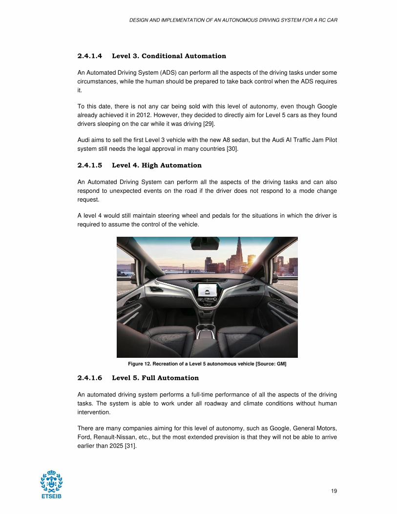
2.4.1.5 Level 4. High Automation
An Automated Driving System can perform all the aspects of the driving tasks and can also
respond to unexpected events on the road if the driver does not respond to a mode change
request.
A level 4 would still maintain steering wheel and pedals for the situations in which the driver is
required to assume the control of the vehicle.
Figure 12. Recreation of a Level 5 autonomous vehicle [Source: GM]
2.4.1.6 Level 5. Full Automation
An automated driving system performs a full-time performance of all the aspects of the driving
tasks. The system is able to work under all roadway and climate conditions without human
intervention.
There are many companies aiming for this level of autonomy, such as Google, General Motors,
Ford, Renault-Nissan, etc., but the most extended prevision is that they will not be able to arrive
earlier than 2025 [31].
DESIGN AND IMPLEMENTATION OF AN AUTONOMOUS DRIVING SYSTEM FOR A RC CAR
20
2.4.2 Companies
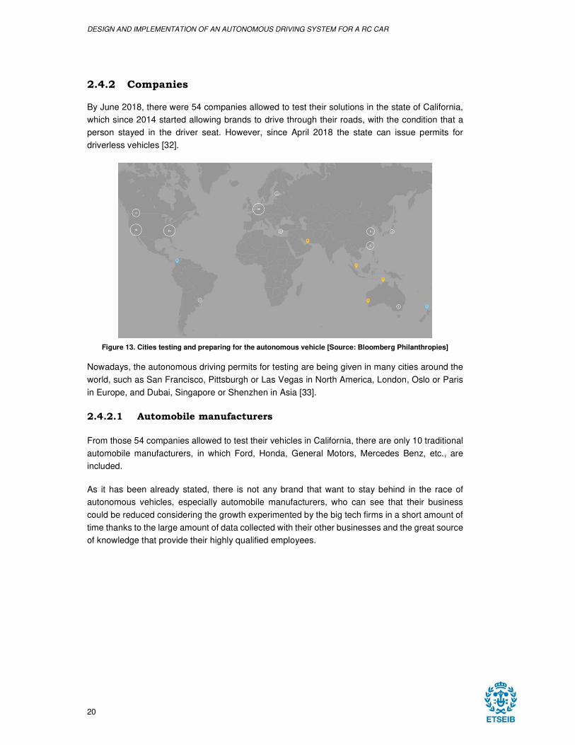
By June 2018, there were 54 companies allowed to test their solutions in the state of California,
which since 2014 started allowing brands to drive through their roads, with the condition that a
person stayed in the driver seat. However, since April 2018 the state can issue permits for
driverless vehicles [32].
Figure 13. Cities testing and preparing for the autonomous vehicle [Source: Bloomberg Philanthropies]
Nowadays, the autonomous driving permits for testing are being given in many cities around the
world, such as San Francisco, Pittsburgh or Las Vegas in North America, London, Oslo or Paris
in Europe, and Dubai, Singapore or Shenzhen in Asia [33].
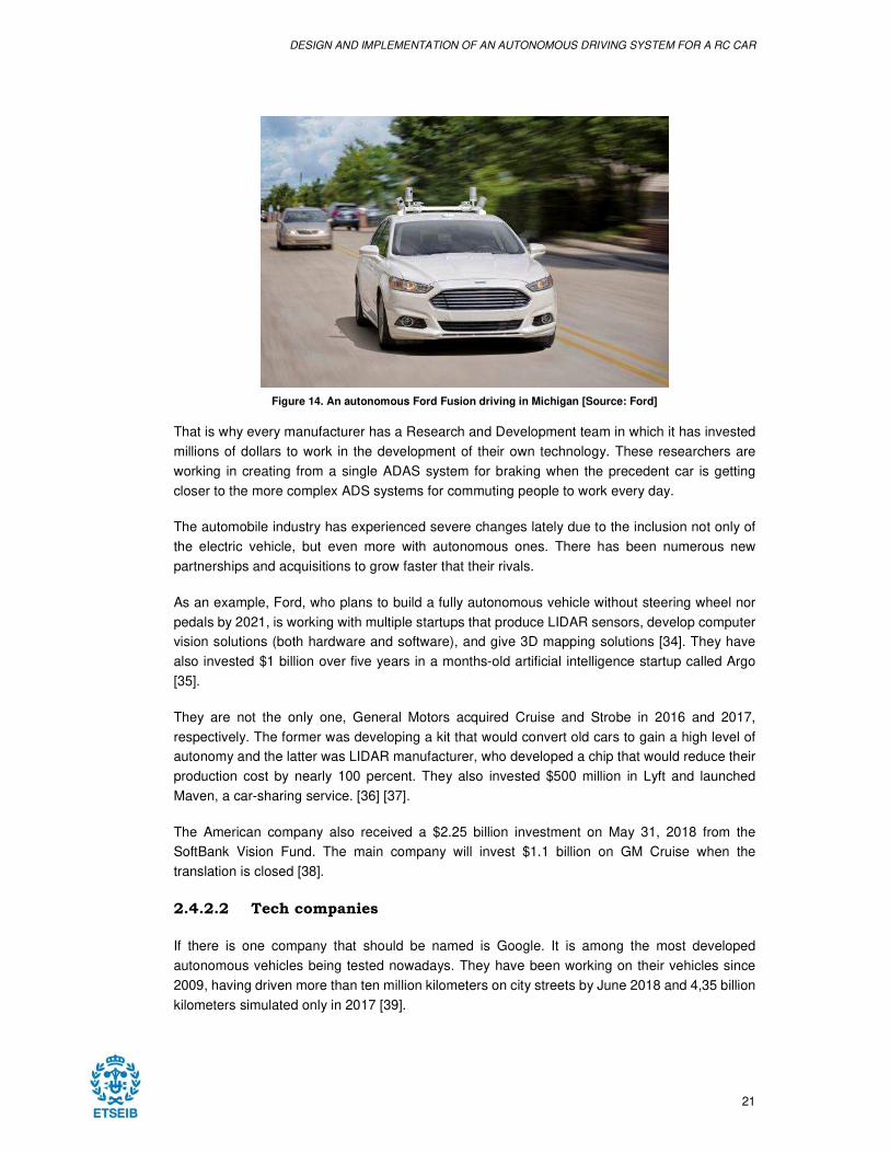
2.4.2.1 Automobile manufacturers
From those 54 companies allowed to test their vehicles in California, there are only 10 traditional
automobile manufacturers, in which Ford, Honda, General Motors, Mercedes Benz, etc., are
included.
As it has been already stated, there is not any brand that want to stay behind in the race of
autonomous vehicles, especially automobile manufacturers, who can see that their business
could be reduced considering the growth experimented by the big tech firms in a short amount of
time thanks to the large amount of data collected with their other businesses and the great source
of knowledge that provide their highly qualified employees.
DESIGN AND IMPLEMENTATION OF AN AUTONOMOUS DRIVING SYSTEM FOR A RC CAR
21
Figure 14. An autonomous Ford Fusion driving in Michigan [Source: Ford]
That is why every manufacturer has a Research and Development team in which it has invested
millions of dollars to work in the development of their own technology. These researchers are
working in creating from a single ADAS system for braking when the precedent car is getting
closer to the more complex ADS systems for commuting people to work every day.
The automobile industry has experienced severe changes lately due to the inclusion not only of
the electric vehicle, but even more with autonomous ones. There has been numerous new
partnerships and acquisitions to grow faster that their rivals.
As an example, Ford, who plans to build a fully autonomous vehicle without steering wheel nor
pedals by 2021, is working with multiple startups that produce LIDAR sensors, develop computer
vision solutions (both hardware and software), and give 3D mapping solutions [34]. They have
also invested $1 billion over five years in a months-old artificial intelligence startup called Argo
[35].
They are not the only one, General Motors acquired Cruise and Strobe in 2016 and 2017,
respectively. The former was developing a kit that would convert old cars to gain a high level of
autonomy and the latter was LIDAR manufacturer, who developed a chip that would reduce their
production cost by nearly 100 percent. They also invested $500 million in Lyft and launched
Maven, a car-sharing service. [36] [37].
The American company also received a $2.25 billion investment on May 31, 2018 from the
SoftBank Vision Fund. The main company will invest $1.1 billion on GM Cruise when the
translation is closed [38].
2.4.2.2 Tech companies
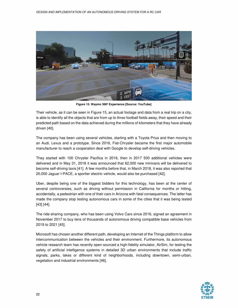
If there is one company that should be named is Google. It is among the most developed
autonomous vehicles being tested nowadays. They have been working on their vehicles since
2009, having driven more than ten million kilometers on city streets by June 2018 and 4,35 billion
kilometers simulated only in 2017 [39].
DESIGN AND IMPLEMENTATION OF AN AUTONOMOUS DRIVING SYSTEM FOR A RC CAR
22
Figure 15. Waymo 360º Experience [Source: YouTube]
Their vehicle, as it can be seen in Figure 15, an actual footage and data from a real trip on a city,
is able to identify all the objects that are from up to three football fields away, their speed and their
predicted path based on the data achieved during the millions of kilometers that they have already
driven [40].
The company has been using several vehicles, starting with a Toyota Prius and then moving to
an Audi, Lexus and a prototype. Since 2016, Fiat-Chrysler became the first major automobile
manufacturer to reach a cooperation deal with Google to develop self-driving vehicles.
They started with 100 Chrysler Pacifica in 2016, then in 2017 500 additional vehicles were
delivered and in May 31, 2018 it was announced that 62,000 new minivans will be delivered to
become self-driving taxis [41]. A few months before that, in March 2018, it was also reported that
20,000 Jaguar I-PACE, a sportier electric vehicle, would also be purchased [42].
Uber, despite being one of the biggest bidders for this technology, has been at the center of
several controversies, such as driving without permission in California for months or hitting,
accidentally, a pedestrian with one of their cars in Arizona with fatal consequences. The latter has
made the company stop testing autonomous cars in some of the cities that it was being tested
[43] [44].
The ride-sharing company, who has been using Volvo Cars since 2016, signed an agreement in
November 2017 to buy tens of thousands of autonomous driving compatible base vehicles from
2019 to 2021 [45].
Microsoft has chosen another different path, developing an Internet of the Things platform to allow
intercommunication between the vehicles and their environment. Furthermore, its autonomous
vehicle research team has recently open-sourced a high-fidelity simulator, AirSim, for testing the
safety of artificial intelligence systems in detailed 3D urban environments that include traffic
signals, parks, lakes or different kind of neighborhoods, including downtown, semi-urban,
vegetation and industrial environments [46].
DESIGN AND IMPLEMENTATION OF AN AUTONOMOUS DRIVING SYSTEM FOR A RC CAR
23
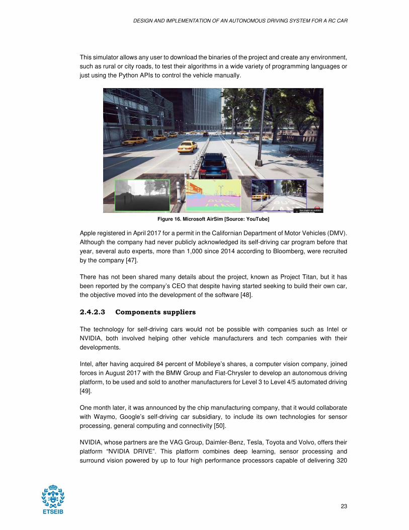
This simulator allows any user to download the binaries of the project and create any environment,
such as rural or city roads, to test their algorithms in a wide variety of programming languages or
just using the Python APIs to control the vehicle manually.
Figure 16. Microsoft AirSim [Source: YouTube]
Apple registered in April 2017 for a permit in the Californian Department of Motor Vehicles (DMV).
Although the company had never publicly acknowledged its self-driving car program before that
year, several auto experts, more than 1,000 since 2014 according to Bloomberg, were recruited
by the company [47].
There has not been shared many details about the project, known as Project Titan, but it has
been reported by the company’s CEO that despite having started seeking to build their own car,
the objective moved into the development of the software [48].
2.4.2.3 Components suppliers
The technology for self-driving cars would not be possible with companies such as Intel or
NVIDIA, both involved helping other vehicle manufacturers and tech companies with their
developments.
Intel, after having acquired 84 percent of Mobileye’s shares, a computer vision company, joined
forces in August 2017 with the BMW Group and Fiat-Chrysler to develop an autonomous driving
platform, to be used and sold to another manufacturers for Level 3 to Level 4/5 automated driving
[49].
One month later, it was announced by the chip manufacturing company, that it would collaborate
with Waymo, Google’s self-driving car subsidiary, to include its own technologies for sensor
processing, general computing and connectivity [50].
NVIDIA, whose partners are the VAG Group, Daimler-Benz, Tesla, Toyota and Volvo, offers their
platform “NVIDIA DRIVE”. This platform combines deep learning, sensor processing and
surround vision powered by up to four high performance processors capable of delivering 320
DESIGN AND IMPLEMENTATION OF AN AUTONOMOUS DRIVING SYSTEM FOR A RC CAR
24
trillion operations per seconds (TOPS3) to be able to reach the Level 5 of autonomous driving
[51].
Aptiv, also known as Delphi Automotive, purchased Ottomatika in August 2015, a Carnegie
Mellon University startup that provides software and systems development for self-driving
vehicles [52].
Delphi Automotive also acquired nuTonomy in October 2017, a company that develops
autonomous driving software and who has been testing vehicles with in Boston and Singapore.
The former had relationships with Mobileye, while the latter had collaborations with Lyft, Grab,
and the PSA Group [53].
The German automotive components supplier Bosch is collaborating with Daimler in the
development of reliable systems and software related to perception, trajectory planning, safety
and more. They plan to launch a traffic jam pilot that works up to 60 km/h between 2018 and
2019, a Level 3 vehicle, before launching a highway pilot by the beginning of the next decade.
2.4.3 Statistics
The California Department of Motor Vehicles were submitted 20 reports by the autonomous
vehicle testers, eight of which did not drive any mile. The majority of the remaining reports, which
go from December 2016 to November 2017, reflects the development of the autonomous vehicle
of each manufacturer [54].
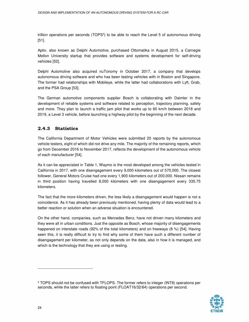
As it can be appreciated in Table 1, Waymo is the most developed among the vehicles tested in
California in 2017, with one disengagement every 9,000 kilometers out of 570,000. The closest
follower, General Motors Cruise had one every 1,900 kilometers out of 200,000. Nissan remains
in third position having travelled 8,000 kilometers with one disengagement every 335.75
kilometers.
The fact that the more kilometers driven, the less likely a disengagement would happen is not a
coincidence. As it has already been previously mentioned, having plenty of data would lead to a
better reaction or solution when an adverse situation is encountered.
On the other hand, companies, such as Mercedes Benz, have not driven many kilometers and
they were all in urban conditions. Just the opposite as Bosch, whose majority of disengagements
happened on interstate roads (92% of the total kilometers) and on freeways (8 %) [54]. Having
seen this, it is really difficult to try to find why some of them have such a different number of
disengagement per kilometer, as not only depends on the data, also in how it is managed, and
which is the technology that they are using or testing.
3 TOPS should not be confused with TFLOPS. The former refers to integer (INT8) operations per seconds, while the latter refers to floating point (FLOAT16/32/64) operations per second.
DESIGN AND IMPLEMENTATION OF AN AUTONOMOUS DRIVING SYSTEM FOR A RC CAR
25
Vehicles Kilometers Disengagements km/Dis.
Waymo 567,364.77 63.00 9,005.79
GM Cruise LLC 201,167.50 105.00 1,915.88
Nissan 8,057.97 24.00 335.75
Zoox, Inc. 3,611.36 14.00 257.95
Drive.ai, Inc. 10,576.58 151.00 70.04
Baidu USA LLC 3,173.20 48.00 66.11
Telenav, Inc. 3,225.12 58.00 55.61
Delphi Automotive 2,913.87 81.00 35.97
NVIDIA 236.57 15.00 15.77
Valeo 923.92 215.00 4.30
Bosch 2,343.20 595.00 3.94
Mercedes Benz 1,750.48 842.00 2.08
Table 1. Autonomous Vehicle Disengagement Reports 2017 [Source: DMV CA]
Besides the disengagements, there have also been some accidents that prove that neither the
technology nor the society is still ready. The firsts known are not probably what it is being
described here as autonomous vehicles, but an assistance system such as those that brakes the
car if the precedent is slowing down or the ones to keep the car between the lanes.
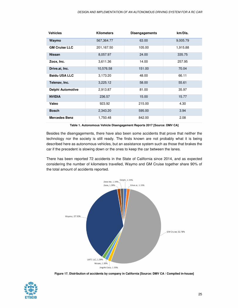
There has been reported 72 accidents in the State of California since 2014, and as expected
considering the number of kilometers travelled, Waymo and GM Cruise together share 90% of
the total amount of accidents reported.
Figure 17. Distribution of accidents by company in California [Source: DMV CA / Compiled in-house]
DESIGN AND IMPLEMENTATION OF AN AUTONOMOUS DRIVING SYSTEM FOR A RC CAR
26
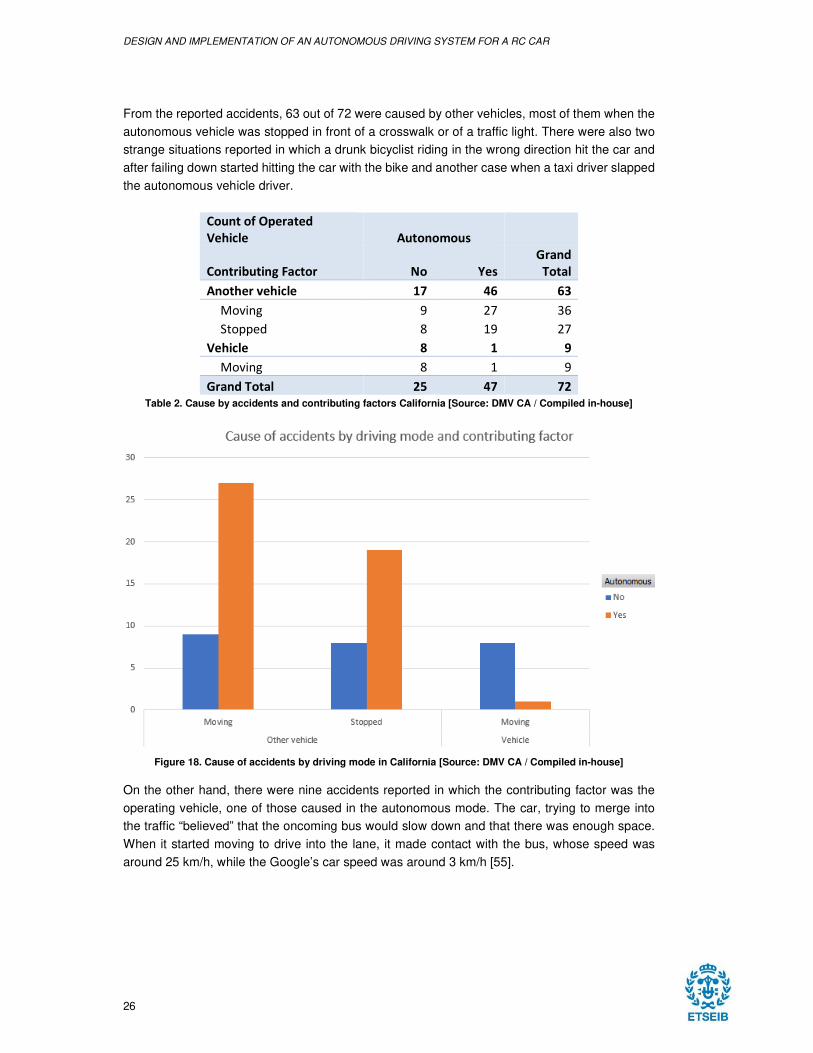
From the reported accidents, 63 out of 72 were caused by other vehicles, most of them when the
autonomous vehicle was stopped in front of a crosswalk or of a traffic light. There were also two
strange situations reported in which a drunk bicyclist riding in the wrong direction hit the car and
after failing down started hitting the car with the bike and another case when a taxi driver slapped
the autonomous vehicle driver.
Count of Operated
Vehicle Autonomous
Contributing Factor No Yes
Grand
Total
Another vehicle 17 46 63
Moving 9 27 36
Stopped 8 19 27
Vehicle 8 1 9
Moving 8 1 9
Grand Total 25 47 72
Table 2. Cause by accidents and contributing factors California [Source: DMV CA / Compiled in-house]
Figure 18. Cause of accidents by driving mode in California [Source: DMV CA / Compiled in-house]
On the other hand, there were nine accidents reported in which the contributing factor was the
operating vehicle, one of those caused in the autonomous mode. The car, trying to merge into
the traffic “believed” that the oncoming bus would slow down and that there was enough space.
When it started moving to drive into the lane, it made contact with the bus, whose speed was
around 25 km/h, while the Google’s car speed was around 3 km/h [55].
DESIGN AND IMPLEMENTATION OF AN AUTONOMOUS DRIVING SYSTEM FOR A RC CAR
27
3. HARDWARE
3.1 JETSON TX2
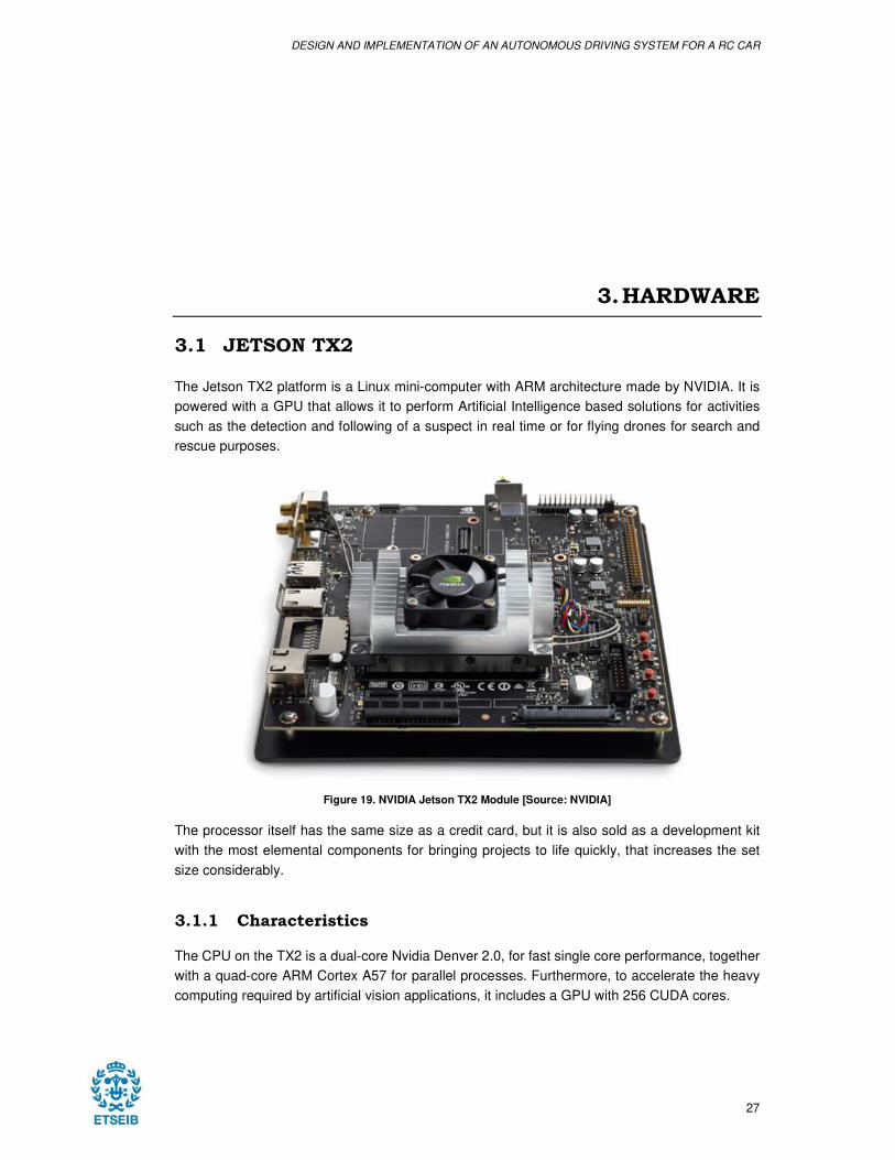
The Jetson TX2 platform is a Linux mini-computer with ARM architecture made by NVIDIA. It is
powered with a GPU that allows it to perform Artificial Intelligence based solutions for activities
such as the detection and following of a suspect in real time or for flying drones for search and
rescue purposes.
Figure 19. NVIDIA Jetson TX2 Module [Source: NVIDIA]
The processor itself has the same size as a credit card, but it is also sold as a development kit
with the most elemental components for bringing projects to life quickly, that increases the set
size considerably.
3.1.1 Characteristics
The CPU on the TX2 is a dual-core Nvidia Denver 2.0, for fast single core performance, together
with a quad-core ARM Cortex A57 for parallel processes. Furthermore, to accelerate the heavy
computing required by artificial vision applications, it includes a GPU with 256 CUDA cores.
3. HARDWARE
28
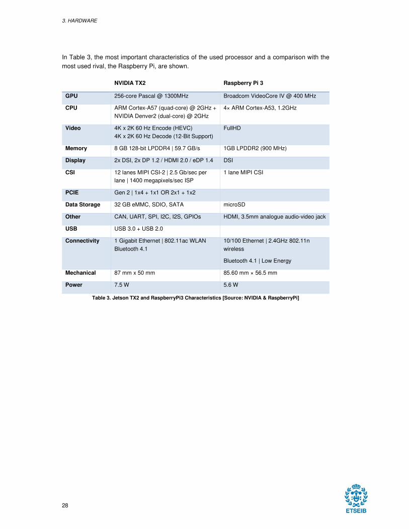
In Table 3, the most important characteristics of the used processor and a comparison with the
most used rival, the Raspberry Pi, are shown.
NVIDIA TX2 Raspberry Pi 3
GPU 256-core Pascal @ 1300MHz Broadcom VideoCore IV @ 400 MHz
CPU ARM Cortex-A57 (quad-core) @ 2GHz +
NVIDIA Denver2 (dual-core) @ 2GHz
4× ARM Cortex-A53, 1.2GHz
Video 4K x 2K 60 Hz Encode (HEVC)
4K x 2K 60 Hz Decode (12-Bit Support)
FullHD
Memory 8 GB 128-bit LPDDR4 | 59.7 GB/s 1GB LPDDR2 (900 MHz)
Display 2x DSI, 2x DP 1.2 / HDMI 2.0 / eDP 1.4 DSI
CSI 12 lanes MIPI CSI-2 | 2.5 Gb/sec per
lane | 1400 megapixels/sec ISP
1 lane MIPI CSI
PCIE Gen 2 | 1x4 + 1x1 OR 2x1 + 1x2
Data Storage 32 GB eMMC, SDIO, SATA microSD
Other CAN, UART, SPI, I2C, I2S, GPIOs HDMI, 3.5mm analogue audio-video jack
USB USB 3.0 + USB 2.0
Connectivity 1 Gigabit Ethernet | 802.11ac WLAN
Bluetooth 4.1
10/100 Ethernet | 2.4GHz 802.11n
wireless
Bluetooth 4.1 | Low Energy
Mechanical 87 mm x 50 mm 85.60 mm × 56.5 mm
Power 7.5 W 5.6 W
Table 3. Jetson TX2 and RaspberryPi3 Characteristics [Source: NVIDIA & RaspberryPi]
DESIGN AND IMPLEMENTATION OF AN AUTONOMOUS DRIVING SYSTEM FOR A RC CAR
29
3.2 VEHICLE
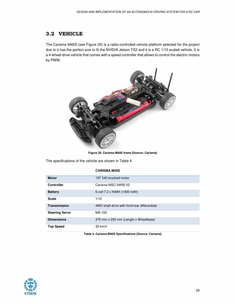
The Carisma M40S (see Figure 20) is a radio-controlled vehicle platform selected for the project
due to it has the perfect size to fit the NVIDIA Jetson TX2 and it is a RC 1/10 scaled vehicle. It is
a 4-wheel drive vehicle that comes with a speed controller that allows to control the electric motors
by PWM.
Figure 20. Carisma M40S frame [Source: Carisma]
The specifications of the vehicle are shown in Table 4.
CARISMA M40S
Motor 19T 540 brushed motor
Controller Carisma MSC-04RB V2
Battery 6-cell 7.2 v NiMH (1400 mAh)
Scale 1/10
Transmission 4WD shaft drive with front/rear differentials
Steering Servo MS-103
Dimensions 375 mm x 255 mm (Length x Wheelbase)
Top Speed 30 km/h
Table 4. Carisma M40S Specifications [Source: Carisma]
3. HARDWARE
30
3.3 ADAFRUIT PCA9685
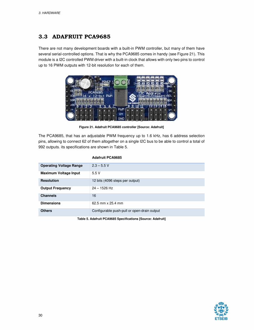
There are not many development boards with a built-in PWM controller, but many of them have
several serial-controlled options. That is why the PCA9685 comes in handy (see Figure 21). This
module is a I2C controlled PWM driver with a built-in clock that allows with only two pins to control
up to 16 PWM outputs with 12-bit resolution for each of them.
Figure 21. Adafruit PCA9685 controller [Source: Adafruit]
The PCA9685, that has an adjustable PWM frequency up to 1.6 kHz, has 6 address selection
pins, allowing to connect 62 of them altogether on a single I2C bus to be able to control a total of
992 outputs. its specifications are shown in Table 5.
Adafruit PCA9685
Operating Voltage Range 2.3 – 5.5 V
Maximum Voltage Input 5.5 V
Resolution 12 bits (4096 steps per output)
Output Frequency 24 – 1526 Hz
Channels 16
Dimensions 62.5 mm x 25.4 mm
Others Configurable push-pull or open-drain output
Table 5. Adafruit PCA9685 Specifications [Source: Adafruit]
DESIGN AND IMPLEMENTATION OF AN AUTONOMOUS DRIVING SYSTEM FOR A RC CAR
31
4. SOFTWARE
4.1 TECHNOLOGIES
In this section it will be detailed the libraries and technologies used to perform the project and
also it will be explained how they were implemented.
4.1.1 OpenCV
OpenCV (Open Source Computer Vision Library) is the leading open source library for computer
vision, image processing and machine learning, designed for computational efficiency and with a
strong focus on real-time applications [56].
Figure 22. OpenCV Logo [Source: Wikipedia]
OpenCV is released under a BSD license, which makes it free for both academic and commercial
use. It has interfaces in C++, Python, Java and MATLAB and supports Windows, Linux, Mac OS
and Android but it was written and optimized natively in C++. It also has a templated interface that
works seamlessly with STL containers.
The library has more than 2,500 optimized algorithms, including both classic and cutting-edge
computer vision and machine learning algorithms, which can be used to detect and recognize
faces or objects, classify actions in videos, track moving objects, extract 3D models of objects,
etc.
4. SOFTWARE
32
The library is estimated to have a larger than 47 thousand active users community and a number
of downloads that exceeds 14 million. It is used in commercial, research and governmental
applications.
In the commercial side, companies such as Google, Microsoft, Intel, IBM, Honda or Toyota use
it, almost any university project related to computer vision use it too. In the public spectrum it is
used mainly for city surveillance by the Governments However, there are interesting projects that
detect and explain artworks when visiting museums [57].
OpenCV has a modular structure, the package includes several shared or static libraries, which
are divided in the following modules [58]:
− Core Functionality. It defines basic data structures.
− Image Processing. Linear and non-linear image filtering, geometrical image
transformations, color space conversion, histograms, etc.
− Video. Video analysis module that includes motion estimation, background subtraction
and object tracking algorithms.
− Calibration 3D. Multiple-view geometry algorithms, as well as elements for 3D
reconstruction.
− Features 2D. Salient feature detectors, descriptors and descriptor matchers.
− Object Detection. Detection of objects and instances of predefined classes.
− High GUI. An easy to use interface to simple UI capabilities.
− Video I/O. Interface to video capturing and video codecs.
− GPU. GPU-accelerated algorithms.
4.1.2 TensorFlow
TensorFlow is an open source library for high performance numerical computation, whose flexible
architecture enables its users to deploy computation to one or more CPUs or GPUs in a desktop,
a server, or a mobile device without rewriting code [59].
Figure 23. TensorFlow Logo [Source: Wikipedia]
DESIGN AND IMPLEMENTATION OF AN AUTONOMOUS DRIVING SYSTEM FOR A RC CAR
33
TensorFlow was developed by researchers and engineers from the Google Brain team and
Google’s Machine Intelligence Research organization to conduct machine learning and deep
neural networks research.
The system has been used in production applications in several areas of computer science and
other fields, such as speech recognition, computer vision, robotics, information retrieval, natural
language processing and computational drug discovery [60].
There are several companies using TensorFlow, such as Airbnb, AMD, NVIDIA, Uber, SAP,
Google, Airbus, etc. for activities like the following:
− Mozilla. Deep Speech
o A TensorFlow implementation motivated by Baidu's Deep Speech architecture.
o Domain. Speech Recognition
− Google: RankBrain
o A large-scale deployment of deep neural nets for search ranking on
www.google.com.
o Domain. Information Retrieval
− Google: Inception Image Classification Model
o Baseline model and follow on research into highly accurate computer vision
models, starting with the model that won the 2014 ImageNet image classification
challenge
− Google: SmartReply
o Deep LSTM model to automatically generate email responses
− Google & Stanford University. Massively Multitask Networks for Drug Discovery
o A deep neural network model for identifying promising drug candidates.
o Domain. Drug discovery
− Google. On-Device Computer Vision for OCR
o On-device computer vision model to do optical character recognition to enable
real-time translation.
4.1.3 Inter-Integrated Circuit (I2C)
The Inter-Integrated Circuit, or I2C, is a synchronous serial bus found on most microcontrollers
that supports multiple devices on a single two-wire bus developed by Philips Semiconductor (now
NXP Semiconductors) in 1982. Therefore, it allows to reduce the number of external pins on a
microcontroller reducing the cost and size of the device [61] [62].
4. SOFTWARE
34
The I2C compatible devices incorporate a chip that allows them to communicate directly with each
other via the I2C bus, solving the problems encountered when designing digital control circuits.
As it has been stated, only two wires are required for this type of buses, a serial data line (SDA)
and a serial clock line (SCL). The clock signal is always generated by the bus master. However,
some slave devices may force the clock low at times to delay the master sending more data, what
is known as “clock stretching”.
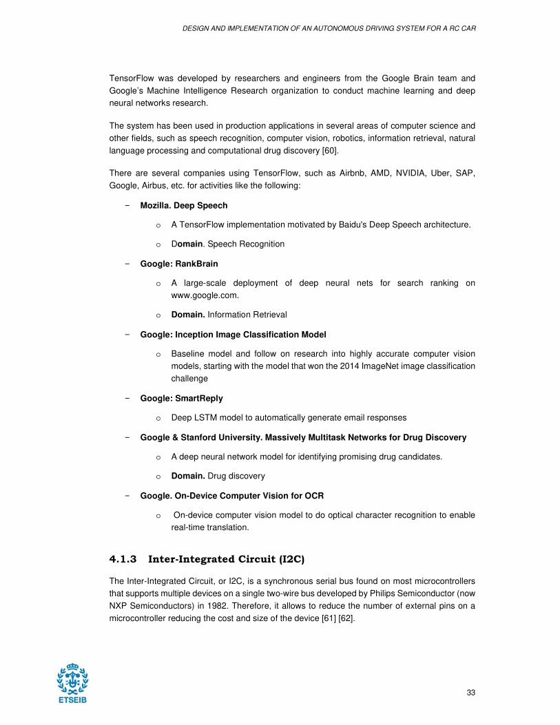
Figure 24. I2C example with two channels [Source: Texas Instruments]
Each of these devices connected to the bus are addressable via software by a unique address
and a master/slave relationship. It can also be more than one master (multi-master), so to prevent
data corruption if two or more initiate data transfer simultaneously, includes collision detection
and arbitration.
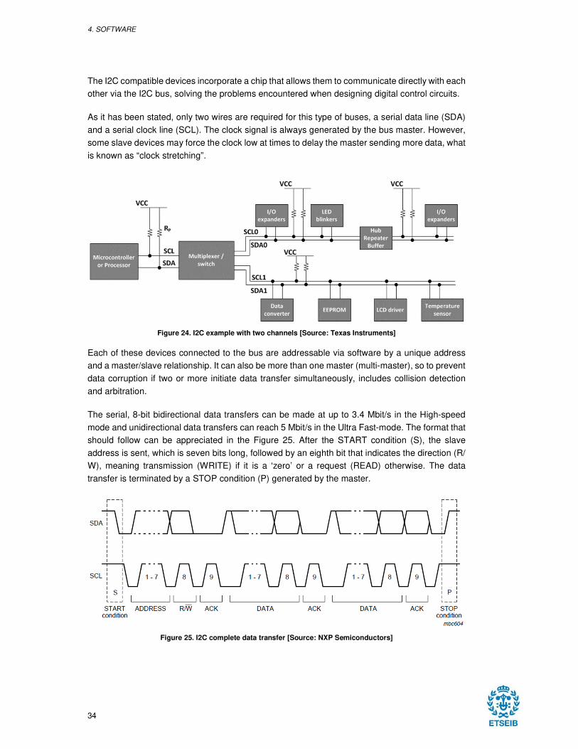
The serial, 8-bit bidirectional data transfers can be made at up to 3.4 Mbit/s in the High-speed
mode and unidirectional data transfers can reach 5 Mbit/s in the Ultra Fast-mode. The format that
should follow can be appreciated in the Figure 25. After the START condition (S), the slave
address is sent, which is seven bits long, followed by an eighth bit that indicates the direction (R/
W), meaning transmission (WRITE) if it is a ‘zero’ or a request (READ) otherwise. The data
transfer is terminated by a STOP condition (P) generated by the master.
Figure 25. I2C complete data transfer [Source: NXP Semiconductors]
DESIGN AND IMPLEMENTATION OF AN AUTONOMOUS DRIVING SYSTEM FOR A RC CAR
35
4.2 IMPLEMENTATION
4.2.1 Road features detection
4.2.1.1 Edge Detection
The Canny Edge detector, one of the most widely used edge detectors in computer vision, is an
algorithm that works in a multi-stage process to detect a wide range of edges in images. In order
to observe properly the steps of this process, an image with more details than the ones used for
the lane detection has been used [63]:
4.2.1.1.1 Convert the image to grayscale
Even though the algorithm can work with more than one channel images, the most common and
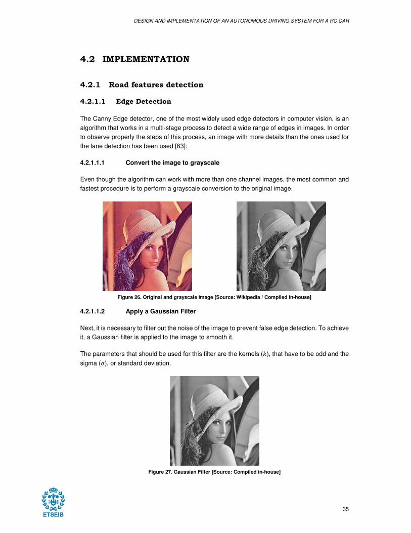
fastest procedure is to perform a grayscale conversion to the original image.
Figure 26. Original and grayscale image [Source: Wikipedia / Compiled in-house]
4.2.1.1.2 Apply a Gaussian Filter
Next, it is necessary to filter out the noise of the image to prevent false edge detection. To achieve
it, a Gaussian filter is applied to the image to smooth it.
The parameters that should be used for this filter are the kernels (�), that have to be odd and the
sigma (�), or standard deviation.
Figure 27. Gaussian Filter [Source: Compiled in-house]
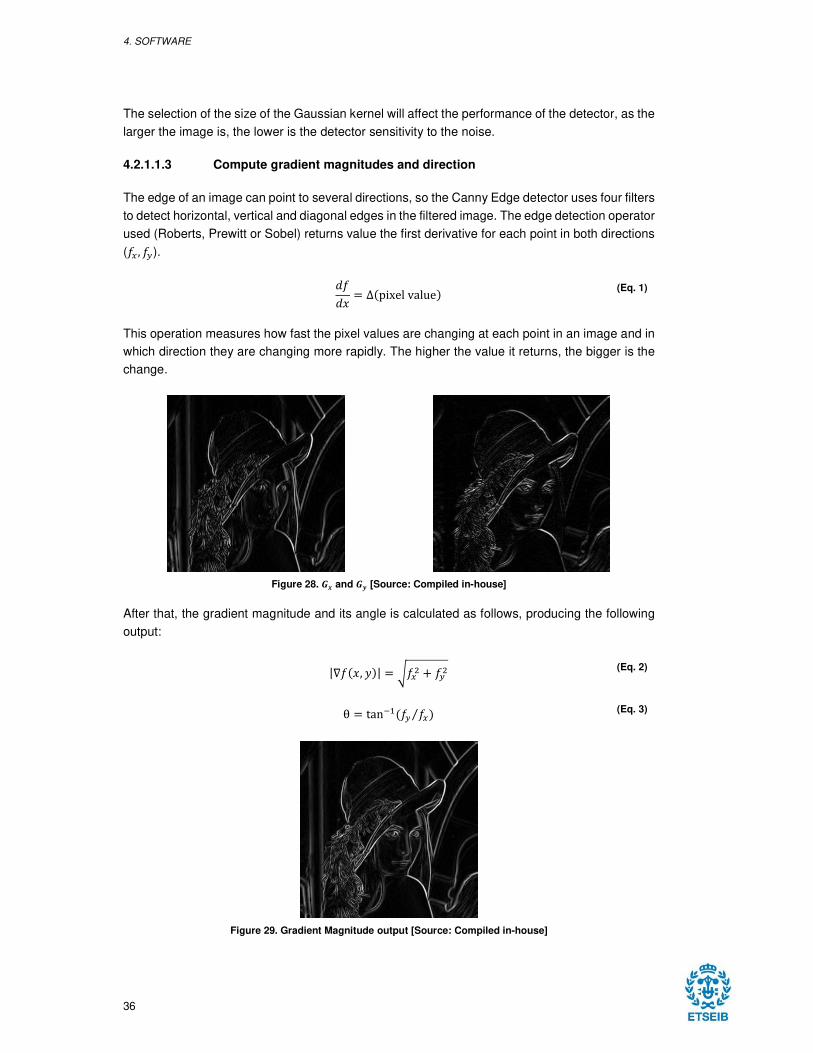
4. SOFTWARE
36
The selection of the size of the Gaussian kernel will affect the performance of the detector, as the
larger the image is, the lower is the detector sensitivity to the noise.
4.2.1.1.3 Compute gradient magnitudes and direction
The edge of an image can point to several directions, so the Canny Edge detector uses four filters
to detect horizontal, vertical and diagonal edges in the filtered image. The edge detection operator
used (Roberts, Prewitt or Sobel) returns value the first derivative for each point in both directions
(�� , ��).
���� = ∆�pixel value!
(Eq. 1)
This operation measures how fast the pixel values are changing at each point in an image and in
which direction they are changing more rapidly. The higher the value it returns, the bigger is the
change.
Figure 28. �� and �� [Source: Compiled in-house]
After that, the gradient magnitude and its angle is calculated as follows, producing the following
output:
|∇���, $!| = %��& ' ��& (Eq. 2)
θ = tan+,��� ��!⁄ (Eq. 3)
Figure 29. Gradient Magnitude output [Source: Compiled in-house]
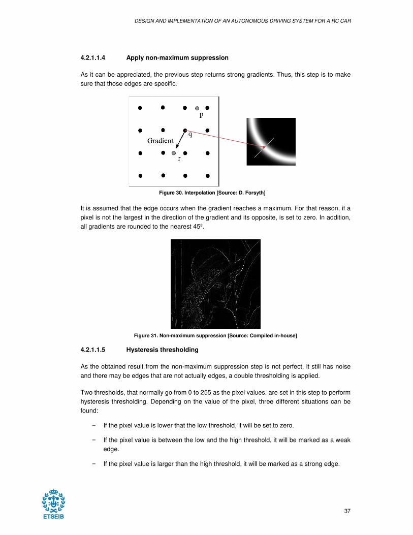
DESIGN AND IMPLEMENTATION OF AN AUTONOMOUS DRIVING SYSTEM FOR A RC CAR
37
4.2.1.1.4 Apply non-maximum suppression
As it can be appreciated, the previous step returns strong gradients. Thus, this step is to make
sure that those edges are specific.
Figure 30. Interpolation [Source: D. Forsyth]
It is assumed that the edge occurs when the gradient reaches a maximum. For that reason, if a
pixel is not the largest in the direction of the gradient and its opposite, is set to zero. In addition,
all gradients are rounded to the nearest 45º.
Figure 31. Non-maximum suppression [Source: Compiled in-house]
4.2.1.1.5 Hysteresis thresholding
As the obtained result from the non-maximum suppression step is not perfect, it still has noise
and there may be edges that are not actually edges, a double thresholding is applied.
Two thresholds, that normally go from 0 to 255 as the pixel values, are set in this step to perform
hysteresis thresholding. Depending on the value of the pixel, three different situations can be
found:
− If the pixel value is lower that the low threshold, it will be set to zero.
− If the pixel value is between the low and the high threshold, it will be marked as a weak
edge.
− If the pixel value is larger than the high threshold, it will be marked as a strong edge.
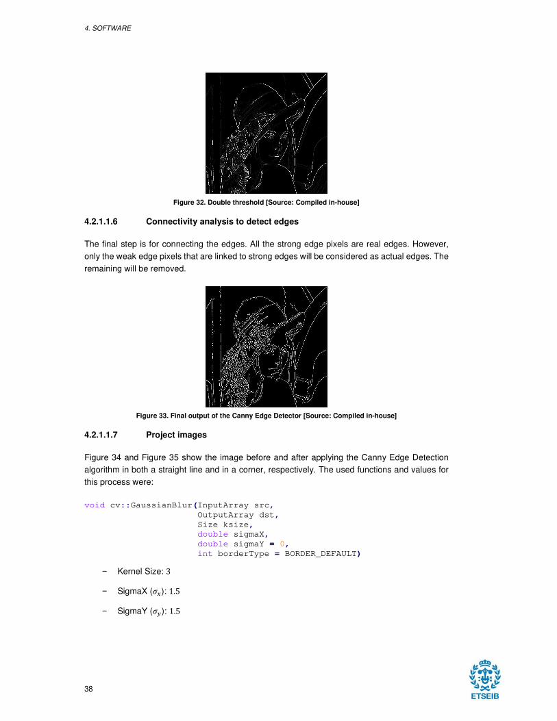
4. SOFTWARE
38
Figure 32. Double threshold [Source: Compiled in-house]
4.2.1.1.6 Connectivity analysis to detect edges
The final step is for connecting the edges. All the strong edge pixels are real edges. However,
only the weak edge pixels that are linked to strong edges will be considered as actual edges. The
remaining will be removed.
Figure 33. Final output of the Canny Edge Detector [Source: Compiled in-house]
4.2.1.1.7 Project images
Figure 34 and Figure 35 show the image before and after applying the Canny Edge Detection
algorithm in both a straight line and in a corner, respectively. The used functions and values for
this process were:
void cv::GaussianBlur(InputArray src,
OutputArray dst,
Size ksize,
double sigmaX,
double sigmaY = 0,
int borderType = BORDER_DEFAULT)
− Kernel Size: 3
− SigmaX (��): 1.5
− SigmaY (��): 1.5
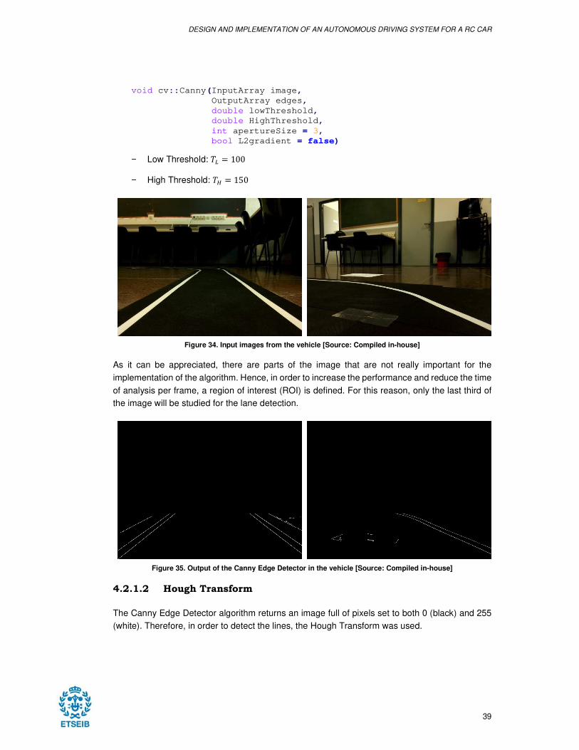
DESIGN AND IMPLEMENTATION OF AN AUTONOMOUS DRIVING SYSTEM FOR A RC CAR
39
void cv::Canny(InputArray image,
OutputArray edges,
double lowThreshold,
double HighThreshold,
int apertureSize = 3,
bool L2gradient = false)
− Low Threshold: 12 = 100
− High Threshold: 14 = 150
Figure 34. Input images from the vehicle [Source: Compiled in-house]
As it can be appreciated, there are parts of the image that are not really important for the
implementation of the algorithm. Hence, in order to increase the performance and reduce the time
of analysis per frame, a region of interest (ROI) is defined. For this reason, only the last third of
the image will be studied for the lane detection.
Figure 35. Output of the Canny Edge Detector in the vehicle [Source: Compiled in-house]
4.2.1.2 Hough Transform
The Canny Edge Detector algorithm returns an image full of pixels set to both 0 (black) and 255
(white). Therefore, in order to detect the lines, the Hough Transform was used.
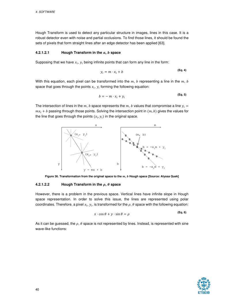
4. SOFTWARE
40
Hough Transform is used to detect any particular structure in images, lines in this case. It is a
robust detector even with noise and partial occlusions. To find those lines, it should be found the
sets of pixels that form straight lines after an edge detector has been applied [63].
4.2.1.2.1 Hough Transform in the 5, � space
Supposing that we have �6, $6 being infinite points that can form any line in the form:
$6 = 7 8 �6 ' 9 (Eq. 4)
With this equation, each pixel can be transformed into the 7, 9 representing a line in the 7, 9
space that goes through the points �6, $6 forming the following equation:
9 = : 7 8 �6 ' $6 (Eq. 5)
The intersection of lines in the 7, 9 space represents the 7, 9 values that compromise a line $6 =7�6 ' 9 passing through those points. Solving the intersection point in �7, 9! gives the values for
the line that goes through the points ��6 , $6! in the original space.
Figure 36. Transformation from the original space to the �, � Hough space [Source: Alyssa Quek]
4.2.1.2.2 Hough Transform in the �, � space
However, there is a problem in the previous space. Vertical lines have infinite slope in Hough
space representation. In order to solve this issue, the lines are represented using polar
coordinates. Therefore, a pixel �6, $6, is transformed for the ;, < space with the following equation:
� 8 cos < ' $ 8 sin < = ; (Eq. 6)
As it can be guessed, the ;, < space is not represented by lines. Instead, is represented with sine
wave-like functions:
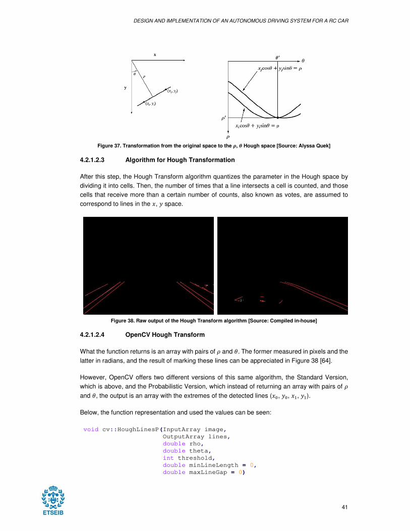
DESIGN AND IMPLEMENTATION OF AN AUTONOMOUS DRIVING SYSTEM FOR A RC CAR
41
Figure 37. Transformation from the original space to the �, � Hough space [Source: Alyssa Quek]
4.2.1.2.3 Algorithm for Hough Transformation
After this step, the Hough Transform algorithm quantizes the parameter in the Hough space by
dividing it into cells. Then, the number of times that a line intersects a cell is counted, and those
cells that receive more than a certain number of counts, also known as votes, are assumed to
correspond to lines in the �, $ space.
Figure 38. Raw output of the Hough Transform algorithm [Source: Compiled in-house]
4.2.1.2.4 OpenCV Hough Transform
What the function returns is an array with pairs of ; and <. The former measured in pixels and the
latter in radians, and the result of marking these lines can be appreciated in Figure 38 [64].
However, OpenCV offers two different versions of this same algorithm, the Standard Version,
which is above, and the Probabilistic Version, which instead of returning an array with pairs of ;
and <, the output is an array with the extremes of the detected lines (�@, $@, �,, $,).
Below, the function representation and used the values can be seen:
void cv::HoughLinesP(InputArray image,
OutputArray lines,
double rho,
double theta,
int threshold,
double minLineLength = 0,
double maxLineGap = 0)
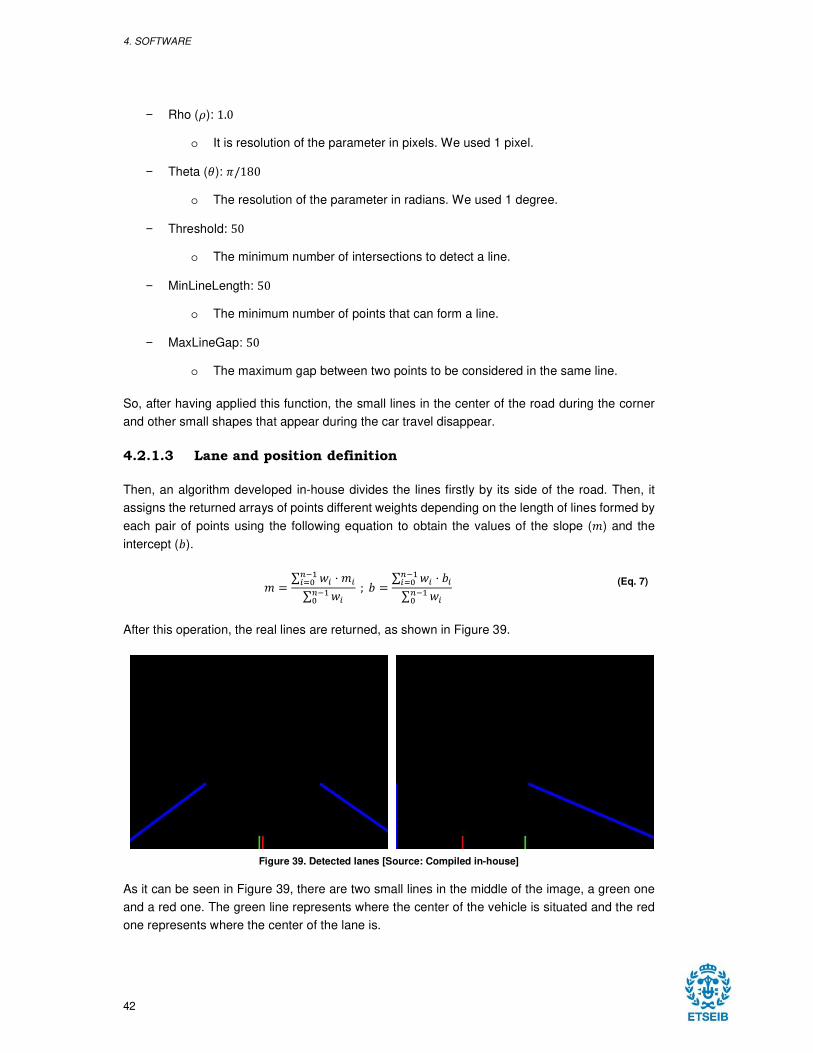
4. SOFTWARE
42
− Rho (;): 1.0
o It is resolution of the parameter in pixels. We used 1 pixel.
− Theta (<): A/180
o The resolution of the parameter in radians. We used 1 degree.
− Threshold: 50
o The minimum number of intersections to detect a line.
− MinLineLength: 50
o The minimum number of points that can form a line.
− MaxLineGap: 50
o The maximum gap between two points to be considered in the same line.
So, after having applied this function, the small lines in the center of the road during the corner
and other small shapes that appear during the car travel disappear.
4.2.1.3 Lane and position definition
Then, an algorithm developed in-house divides the lines firstly by its side of the road. Then, it
assigns the returned arrays of points different weights depending on the length of lines formed by
each pair of points using the following equation to obtain the values of the slope (7) and the
intercept (9).
7 = ∑ E6F+,6G@ 8 76∑ E6F+,@
; 9 = ∑ E6F+,6G@ 8 96∑ E6F+,@
(Eq. 7)
After this operation, the real lines are returned, as shown in Figure 39.
Figure 39. Detected lanes [Source: Compiled in-house]
As it can be seen in Figure 39, there are two small lines in the middle of the image, a green one
and a red one. The green line represents where the center of the vehicle is situated and the red
one represents where the center of the lane is.
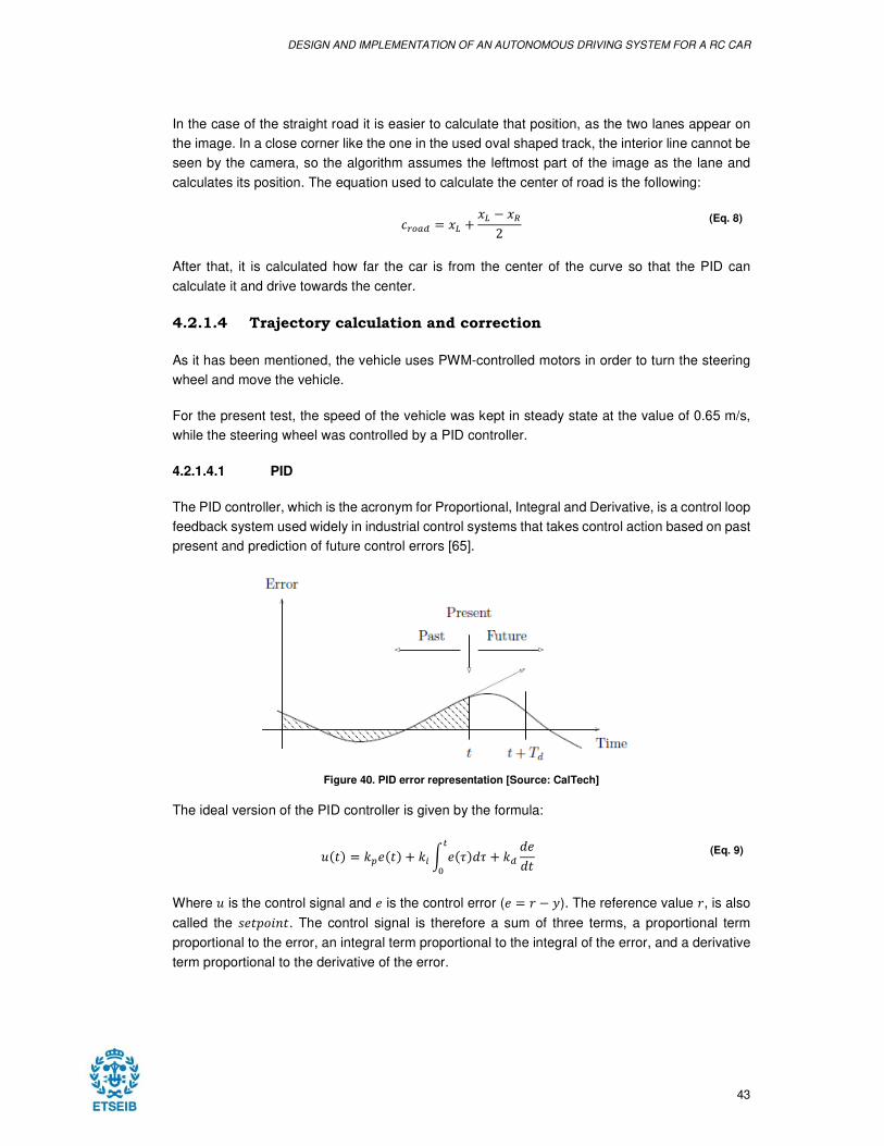
DESIGN AND IMPLEMENTATION OF AN AUTONOMOUS DRIVING SYSTEM FOR A RC CAR
43
In the case of the straight road it is easier to calculate that position, as the two lanes appear on
the image. In a close corner like the one in the used oval shaped track, the interior line cannot be
seen by the camera, so the algorithm assumes the leftmost part of the image as the lane and
calculates its position. The equation used to calculate the center of road is the following:
IJKLM = �2 ' �2 : �N2
(Eq. 8)
After that, it is calculated how far the car is from the center of the curve so that the PID can
calculate it and drive towards the center.
4.2.1.4 Trajectory calculation and correction
As it has been mentioned, the vehicle uses PWM-controlled motors in order to turn the steering
wheel and move the vehicle.
For the present test, the speed of the vehicle was kept in steady state at the value of 0.65 m/s,
while the steering wheel was controlled by a PID controller.
4.2.1.4.1 PID
The PID controller, which is the acronym for Proportional, Integral and Derivative, is a control loop
feedback system used widely in industrial control systems that takes control action based on past
present and prediction of future control errors [65].
Figure 40. PID error representation [Source: CalTech]
The ideal version of the PID controller is given by the formula:
P�Q! = �RS�Q! ' �6 T S�U!�UV
@' �M
�S�Q
(Eq. 9)
Where P is the control signal and S is the control error (S = W : $). The reference value W, is also
called the XSQYZ[\Q. The control signal is therefore a sum of three terms, a proportional term
proportional to the error, an integral term proportional to the integral of the error, and a derivative
term proportional to the derivative of the error.
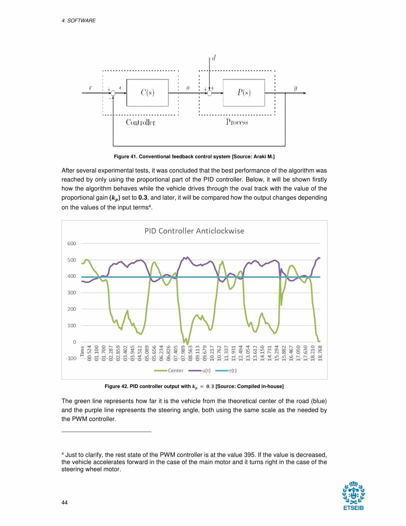
4. SOFTWARE
44
Figure 41. Conventional feedback control system [Source: Araki M.]
After several experimental tests, it was concluded that the best performance of the algorithm was
reached by only using the proportional part of the PID controller. Below, it will be shown firstly
how the algorithm behaves while the vehicle drives through the oval track with the value of the
proportional gain (�) set to 0.3, and later, it will be compared how the output changes depending
on the values of the input terms4.
Figure 42. PID controller output with � = �. � [Source: Compiled in-house]
The green line represents how far it is the vehicle from the theoretical center of the road (blue)
and the purple line represents the steering angle, both using the same scale as the needed by
the PWM controller.
4 Just to clarify, the rest state of the PWM controller is at the value 395. If the value is decreased, the vehicle accelerates forward in the case of the main motor and it turns right in the case of the steering wheel motor.
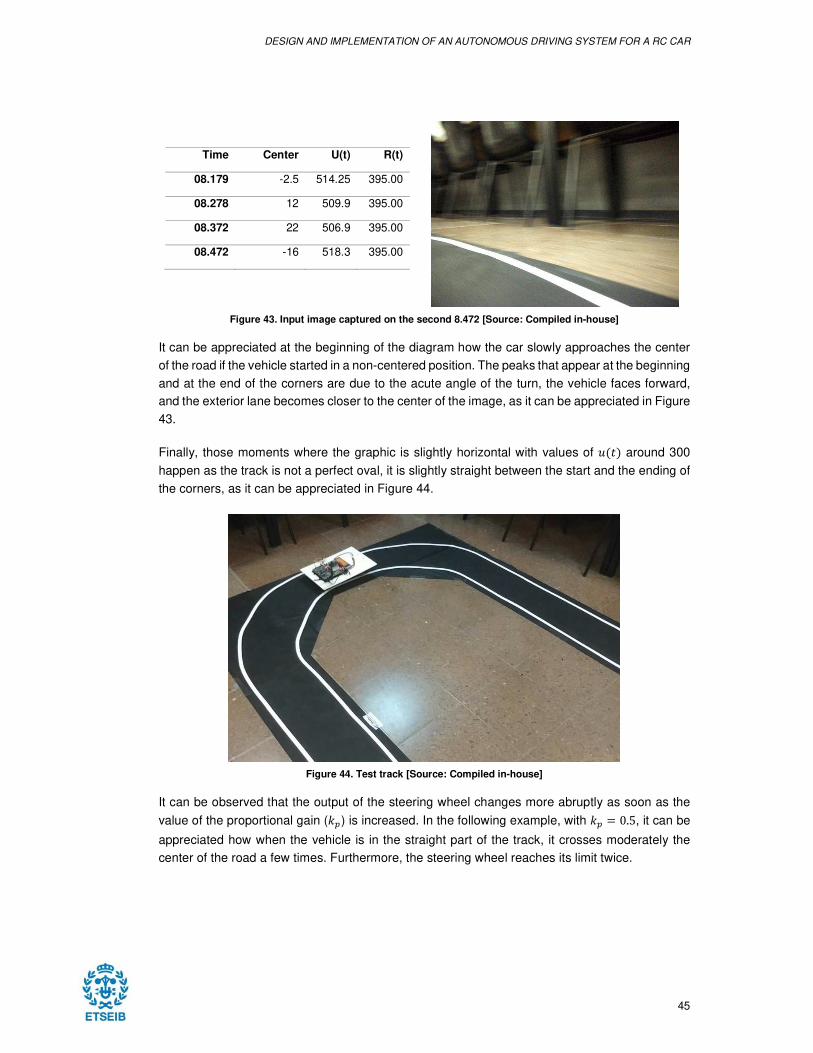
DESIGN AND IMPLEMENTATION OF AN AUTONOMOUS DRIVING SYSTEM FOR A RC CAR
45
Time Center U(t) R(t)
08.179 -2.5 514.25 395.00
08.278 12 509.9 395.00
08.372 22 506.9 395.00
08.472 -16 518.3 395.00
Figure 43. Input image captured on the second 8.472 [Source: Compiled in-house]
It can be appreciated at the beginning of the diagram how the car slowly approaches the center
of the road if the vehicle started in a non-centered position. The peaks that appear at the beginning
and at the end of the corners are due to the acute angle of the turn, the vehicle faces forward,
and the exterior lane becomes closer to the center of the image, as it can be appreciated in Figure
43.
Finally, those moments where the graphic is slightly horizontal with values of P�Q! around 300
happen as the track is not a perfect oval, it is slightly straight between the start and the ending of
the corners, as it can be appreciated in Figure 44.
Figure 44. Test track [Source: Compiled in-house]
It can be observed that the output of the steering wheel changes more abruptly as soon as the
value of the proportional gain (�R) is increased. In the following example, with �R = 0.5, it can be
appreciated how when the vehicle is in the straight part of the track, it crosses moderately the
center of the road a few times. Furthermore, the steering wheel reaches its limit twice.
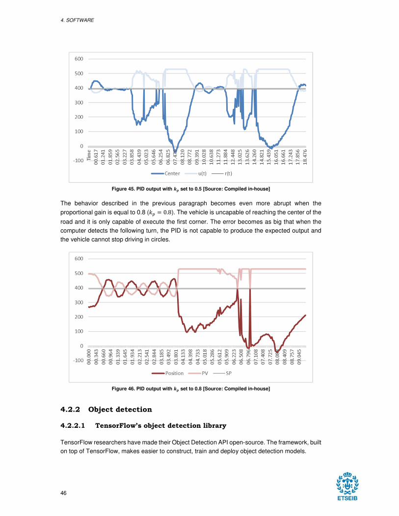
4. SOFTWARE
46
Figure 45. PID output with � set to 0.5 [Source: Compiled in-house]
The behavior described in the previous paragraph becomes even more abrupt when the
proportional gain is equal to 0.8 (�R = 0.8). The vehicle is uncapable of reaching the center of the
road and it is only capable of execute the first corner. The error becomes as big that when the
computer detects the following turn, the PID is not capable to produce the expected output and
the vehicle cannot stop driving in circles.
Figure 46. PID output with � set to 0.8 [Source: Compiled in-house]
4.2.2 Object detection
4.2.2.1 TensorFlow’s object detection library
TensorFlow researchers have made their Object Detection API open-source. The framework, built
on top of TensorFlow, makes easier to construct, train and deploy object detection models.
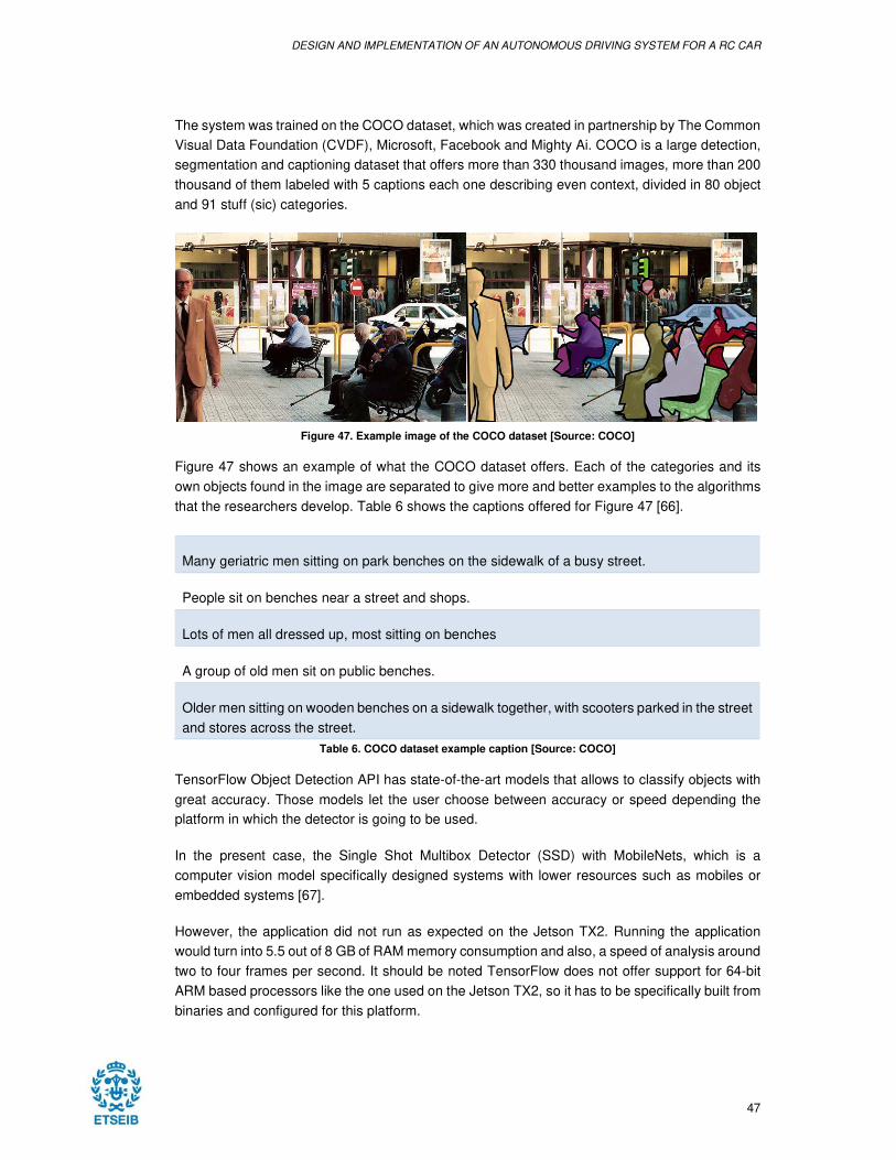
DESIGN AND IMPLEMENTATION OF AN AUTONOMOUS DRIVING SYSTEM FOR A RC CAR
47
The system was trained on the COCO dataset, which was created in partnership by The Common
Visual Data Foundation (CVDF), Microsoft, Facebook and Mighty Ai. COCO is a large detection,
segmentation and captioning dataset that offers more than 330 thousand images, more than 200
thousand of them labeled with 5 captions each one describing even context, divided in 80 object
and 91 stuff (sic) categories.
Figure 47. Example image of the COCO dataset [Source: COCO]
Figure 47 shows an example of what the COCO dataset offers. Each of the categories and its
own objects found in the image are separated to give more and better examples to the algorithms
that the researchers develop. Table 6 shows the captions offered for Figure 47 [66].
Many geriatric men sitting on park benches on the sidewalk of a busy street.
People sit on benches near a street and shops.
Lots of men all dressed up, most sitting on benches
A group of old men sit on public benches.
Older men sitting on wooden benches on a sidewalk together, with scooters parked in the street
and stores across the street.
Table 6. COCO dataset example caption [Source: COCO]
TensorFlow Object Detection API has state-of-the-art models that allows to classify objects with
great accuracy. Those models let the user choose between accuracy or speed depending the
platform in which the detector is going to be used.
In the present case, the Single Shot Multibox Detector (SSD) with MobileNets, which is a
computer vision model specifically designed systems with lower resources such as mobiles or
embedded systems [67].
However, the application did not run as expected on the Jetson TX2. Running the application
would turn into 5.5 out of 8 GB of RAM memory consumption and also, a speed of analysis around
two to four frames per second. It should be noted TensorFlow does not offer support for 64-bit
ARM based processors like the one used on the Jetson TX2, so it has to be specifically built from
binaries and configured for this platform.
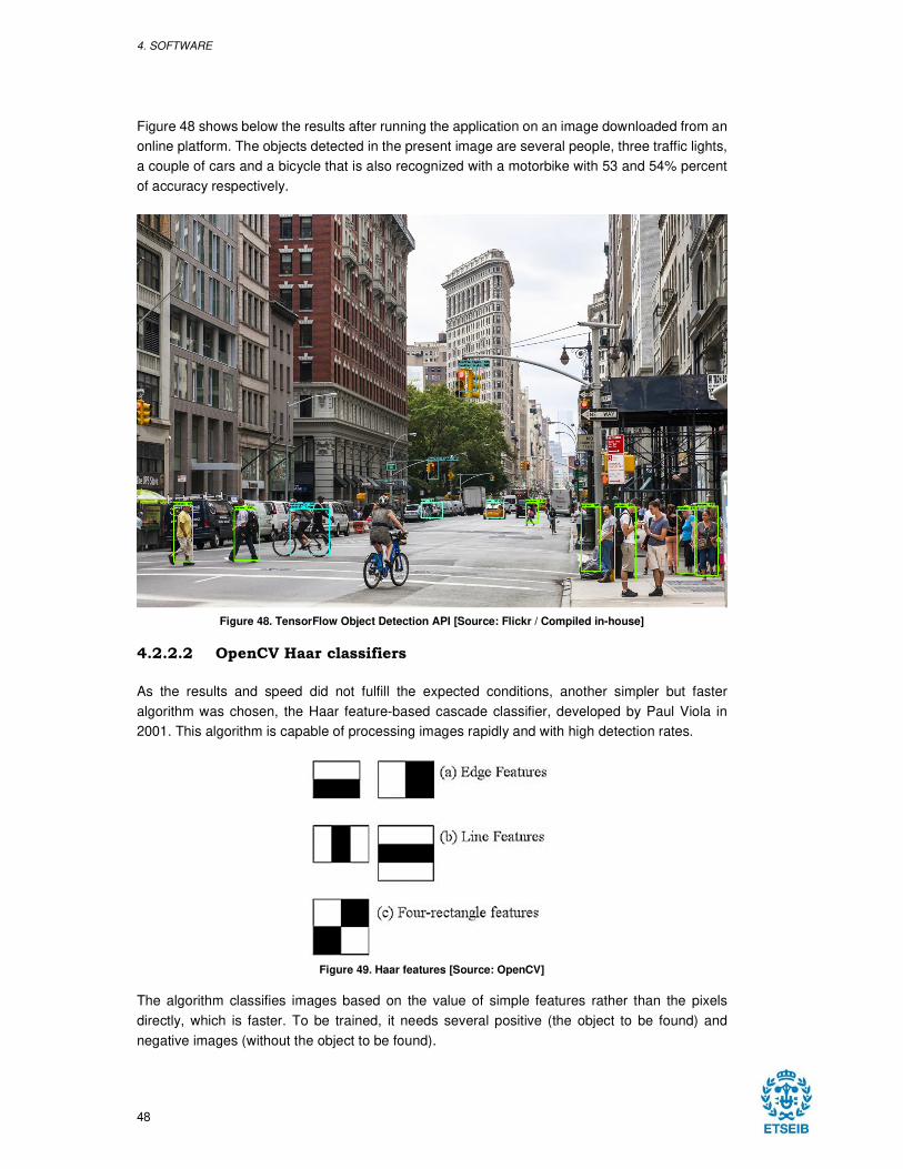
4. SOFTWARE
48
Figure 48 shows below the results after running the application on an image downloaded from an
online platform. The objects detected in the present image are several people, three traffic lights,
a couple of cars and a bicycle that is also recognized with a motorbike with 53 and 54% percent
of accuracy respectively.
Figure 48. TensorFlow Object Detection API [Source: Flickr / Compiled in-house]
4.2.2.2 OpenCV Haar classifiers
As the results and speed did not fulfill the expected conditions, another simpler but faster
algorithm was chosen, the Haar feature-based cascade classifier, developed by Paul Viola in
2001. This algorithm is capable of processing images rapidly and with high detection rates.
Figure 49. Haar features [Source: OpenCV]
The algorithm classifies images based on the value of simple features rather than the pixels
directly, which is faster. To be trained, it needs several positive (the object to be found) and
negative images (without the object to be found).
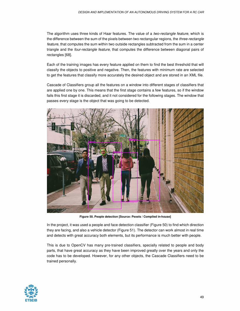
DESIGN AND IMPLEMENTATION OF AN AUTONOMOUS DRIVING SYSTEM FOR A RC CAR
49
The algorithm uses three kinds of Haar features. The value of a two-rectangle feature, which is
the difference between the sum of the pixels between two rectangular regions, the three-rectangle
feature, that computes the sum within two outside rectangles subtracted from the sum in a center
triangle and the four-rectangle feature, that computes the difference between diagonal pairs of
rectangles [68].
Each of the training images has every feature applied on them to find the best threshold that will
classify the objects to positive and negative. Then, the features with minimum rate are selected
to get the features that classify more accurately the desired object and are stored in an XML file.
Cascade of Classifiers group all the features on a window into different stages of classifiers that
are applied one by one. This means that the first stage contains a few features, so if the window
fails this first stage it is discarded, and it not considered for the following stages. The window that
passes every stage is the object that was going to be detected.
Figure 50. People detection [Source: Pexels / Compiled in-house]
In the project, it was used a people and face detection classifier (Figure 50) to find which direction
they are facing, and also a vehicle detector (Figure 51). The detector can work almost in real time
and detects with great accuracy both elements, but its performance is much better with people.
This is due to OpenCV has many pre-trained classifiers, specially related to people and body
parts, that have great accuracy as they have been improved greatly over the years and only the
code has to be developed. However, for any other objects, the Cascade Classifiers need to be
trained personally.
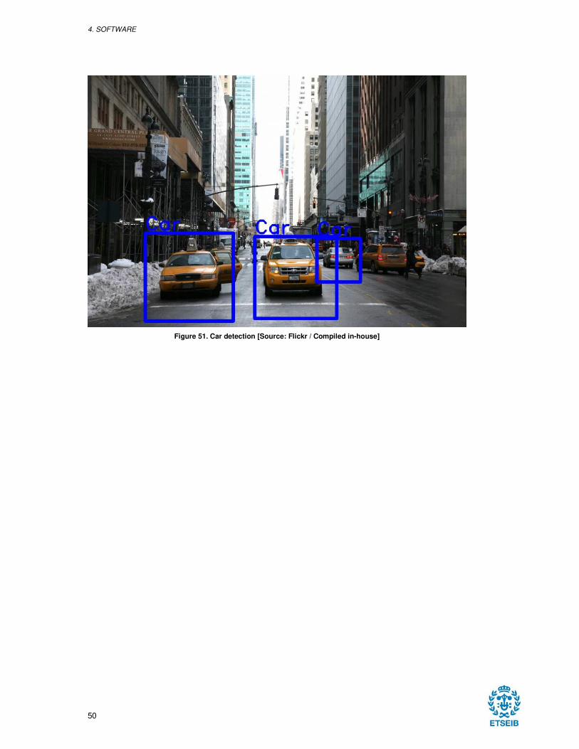
4. SOFTWARE
50
Figure 51. Car detection [Source: Flickr / Compiled in-house]
DESIGN AND IMPLEMENTATION OF AN AUTONOMOUS DRIVING SYSTEM FOR A RC CAR
51
5. CONCLUSIONS
After having done this project and having learnt several new aspects about self-driving cars and
artificial intelligence, it is believed that in a not so long period of time a new revolution will come.
Now there are only a few vehicles being tested, but every company is working not to be left out.
As it has been seen, almost every single accident in which a self-driving car has been involved,
indeed 71 out of 72 accidents that happened in California since the project started have been
caused by human errors. That is why before the vehicle arrives to the market, it must be ensured
that every single situation that can happen is solved.
Vehicles cannot arrive with a level of autonomy different to Level 5, because as it has been shown
lately with already sold Level 2 vehicles, people tend to relax when these vehicles are used and
forget that it is not allowed to be using it without the hands placed in the steering wheel and
focused on what is happening on the road.
Therefore, the approach followed by Waymo, Google’s car division, is considered the most
appropriate, as people will be able not to worry about the car nor the external conditions as the
vehicles will not even have maneuvering devices.
This project would still be considered a Level 2 vehicle that is capable of driving between any
color lanes on a road. The vehicle would even be capable of driving on a road in which only one
line is drawn by driving close to it.
It has also been developed two programs that detect pedestrians and vehicles and know where
they are placed. This would allow to reduce the speed, or even brake, if the object was becoming
closer to the vehicle.

DESIGN AND IMPLEMENTATION OF AN AUTONOMOUS DRIVING SYSTEM FOR A RC CAR
53
6. FUTURE LINES OF RESEARCH
Starting from the state in which the project and society is, the objective of this project will be
putting more focus on developing a completely intelligent system capable of going from one point
to the desired one, with just giving it the instruction, and being able to test in on a real vehicle,
firstly in a closed environment.
Firstly, the vehicle would be trained to be able to detect lines and drive through them instinctively
by feeding an algorithm with several hours of images of point of view cameras with the inputs
given in each situation. This would allow to detect all the posible situations and how the vehicle
reacted to overcome them.
Then, a GPS and an affordable system for object detection, such as a LIDAR or RADAR would
be installed to map the environment and also to be able to know the exact location in which the
vehicle is placed.
The generated signals from those two sensors would be compared with online map services to
confirm that the vehicle is located where it is supposed to be and also to report new information
that occurs on the road, such as a closed road for construction activities, an accident, etc.

DESIGN AND IMPLEMENTATION OF AN AUTONOMOUS DRIVING SYSTEM FOR A RC CAR
55
7. ENVIRONMENTAL IMPACT
Self-driving vehicles will have a very positive effect on the environment. They are more efficient
than humans as they can reach the point of maximum efficiency, if a combustion engine is used,
with great precision.
As cars would be driven more efficiently and not aggressively, there would be less accidents, less
changes of speed through the highway and therefore less traffic jams, which will reduce the
emission of carbon monoxide and other polluting gasses.
Most of the self-driving cars though, are electrical, so there will be no emissions in the vehicle
side. However, it should be studied which would be the environmental costs of mineral extraction
to manufacture batteries and where the electricity consumed by the cars come from, as it is not
the same consuming solar or wind power than consuming carbon.

DESIGN AND IMPLEMENTATION OF AN AUTONOMOUS DRIVING SYSTEM FOR A RC CAR
57
8. BIBLIOGRAPHY
[1] S. Singh, "Critical reasons for crashes investigated in the National Motor Vehicle Crash Causation
Survey," National Highway Traffic Safety Administration, Washington, DC, 2015.
[2] Europen Road Safety Observatory, "Annual Accident Report 2017," Brussels, 2017.
[3] INRIX, "INRIX Global Traffic Scorecard," INRIX, 2017. [Online]. Available:
http://inrix.com/scorecard/. [Accessed 2018 02 25].
[4] Y. Sugiyama, "Traffic Jams Without Bottlenecks," New Journal of Physics, vol. 10, no. March,
2008.
[5] DARPA, "The DARPA Grand Challenge: Ten Years Later," 13 Marzo 2014. [Online]. Available:
https://www.darpa.mil/news-events/2014-03-13. [Accessed 22 Enero 2018].
[6] J. Markoff, "The New York Times," 9 October 2010. [Online]. Available:
https://www.nytimes.com/2010/10/10/science/10google.html. [Accessed 18 04 2018].
[7] Eureka Network, "Programme for a European Traffic System with Highest Efficiency and
Unprecedented Safety," [Online]. Available: http://www.eurekanetwork.org/project/id/45.
[Accessed 04 April 2018].
[8] Center for Photogrammetric Training, "History of Photogrammetry".
[9] S. Russel and P. Norvig, Artificial Ingelligence - A Modern Approach, New Jersey: Pearson
Education, 2009.
[10] J. Hays and A. A. Efros, "Scene Completion Using Millions of Photographs," in SIGGRAPH, San
Diego, CA, 2007.
[11] Symantec Corporation, "2013 Trends," Internet Security Threat Report, vol. 19, p. 14, April 2014.
[12] Symantec Corporation, "Email: Malware, spam, & phising," Internet Security Threat Report, pp.
23-2, April 2017.
[13] Federal Bureau of Investigation, "Business e-mail compromise: The 3.1 billion dollar scam,"
Internet Crime Complaint Center (IC3), 14 June 2016. [Online]. Available:
https://www.ic3.gov/media/2016/160614.aspx#ref1. [Accessed 27 May 2018].
[14] Google, "Google AI Blog," Google, 8 May 2018. [Online]. Available:
https://ai.googleblog.com/2018/05/duplex-ai-system-for-natural-conversation.html. [Accessed 24
May 2018].
ERROR! REFERENCE SOURCE NOT FOUND.. ERROR! REFERENCE SOURCE NOT FOUND.
58
[15] A. van den Oord, S. Dieleman and H. Zen, "WaveNet: A Generative Model for Raw Audio,"
London, 2016.
[16] Google, "DeepMind," Google, 8 September 2016. [Online]. Available:
https://deepmind.com/blog/wavenet-generative-model-raw-audio/. [Accessed 25 May 2018].
[17] M. L. Ginsberg, "Computers, Games and the Real World," Scientific American, 2008. [Online].
Available: http://www.scientificamerican.com:80/1998/1198intelligence/1198ginsberg.html.
[Accessed 27 May 2018].
[18] D. Hassabis and S. David, "AlphaGo Zero: Learning from scratch," DeepMind, 18 October 2017.
[Online]. Available: https://deepmind.com/blog/alphago-zero-learning-scratch/. [Accessed 28 May
2018].
[19] D. Hassabis and D. Silver, "AlphaGo: Mastering the ancient game of Go with Machine Learning,"
Google, 27 January 2016. [Online]. Available: https://ai.googleblog.com/2016/01/alphago-
mastering-ancient-game-of-go.html. [Accessed 28 May 2018].
[20] Y. Wu, M. Schuster, Z. Chen and Q. V. Le, "Google's Neural Machine Translation System," 2016.
[21] Microsoft AI Research, "Achieving Human Parity on Automatic Chinese to English News
Translation," 2018.
[22] DHL and IBM, "Artificial Intelligence in Logistics," DHL Customer Solutions & Innovation, Troisdorf,
2018.
[23] N. Chokshi, "Is Alexa Listening? Amazon Echo Sent Out Recording of Couple's Conversation,"
The New York Times, 25 May 2018. [Online]. Available:
https://www.nytimes.com/2018/05/25/business/amazon-alexa-conversation-shared-echo.html.
[Accessed 04 June 2018].
[24] N. Lawrence, "Deep Learning, Pachinko, and James Watt: Efficiency is the Driver of Uncertainty,"
04 March 2016. [Online]. Available: http://inverseprobability.com/2016/03/04/deep-learning-and-
uncertainty. [Accessed 04 June 2018].
[25] K. Eykholt, I. Evtimov, E. Fernandes, B. Li, A. Rahmati, C. Xiao, A. Prakash, T. Kohno and D.
Song, "Robust Physical-World Attacks on Deep Learning Visual Classification," in Conference on
Computer Vision and Pattern Recognition (CVPR), Salt Lake City, 2018.
[26] M. Burgess, "Facial recognition tech used by UK police is making a ton of mistakes," Wired UK, 04
May 2018. [Online]. Available: http://www.wired.co.uk/article/face-recognition-police-uk-south-
wales-met-notting-hill-carnival. [Accessed 04 June 2018].
[27] I. Evans, "Report: London No Safer for All Its CCTV Cameras," abc News, 25 February 2012.
[Online]. Available: https://abcnews.go.com/International/report-london-safer-cctv-
cameras/story?id=15776976. [Accessed 04 June 2018].
[28] SAE International, " J3016_201609 - Taxonomy and Definitions for Terms Related to Driving
Automation Systems for On-Road Motor Vehicles," 30 September 2016. [Online]. Available:
https://www.sae.org/standards/content/j3016_201609/. [Accessed 10 June 2018].
[29] Google, "Google Self-Driving Car Project - Monthly Report," 01 October 2015. [Online]. Available:
https://static.googleusercontent.com/media/www.google.com/en//selfdrivingcar/files/reports/report-
1015.pdf. [Accessed 10 June 2018].
DESIGN AND IMPLEMENTATION OF AN AUTONOMOUS DRIVING SYSTEM FOR A RC CAR
59
[30] Audi, "Automated driving at a new level: the Audi AI traffic jam pilot," 09 July 2017. [Online].
Available: https://www.audi-mediacenter.com/en/press-releases/automated-driving-at-a-new-level-
the-audi-ai-traffic-jam-pilot-9300. [Accessed 10 June 2018].
[31] R. Dillet, "Renault-Nissan CEO Carlos Ghosn on the future of cars," TechCrunch, 13 October
2016. [Online]. Available: https://techcrunch.com/2016/10/13/renault-nissan-ceo-carlos-ghosn-on-
the-future-of-cars/. [Accessed 10 June 2018].
[32] Department of Motor Vehicles, "Autonomous Vehicles in California," State of California, 1 June
2018. [Online]. Available: https://www.dmv.ca.gov/portal/dmv/detail/vr/autonomous/permit.
[Accessed 10 June 2018].
[33] Bloomberg Philantropies, "Initiative on Cities and Autonomous Vehicles," Bloomberg, 2018.
[Online]. Available: https://avsincities.bloomberg.org/global-atlas. [Accessed 11 June 2018].
[34] J. Golson, "Ford will build an autonomous car without a steering wheel or pedals by 2021," The
Verge, 16 August 2016. [Online]. Available: https://www.theverge.com/2016/8/16/12504300/ford-
autonomous-car-ride-sharing-2021. [Accessed 10 June 2018].
[35] A. Marshall, "Eyeing a self-driving future, Ford drops $1B on an AI startup," Wired, 02 October
2017. [Online]. Available: https://www.wired.com/2017/02/eyeing-self-driving-future-ford-drops-1b-
ai-startup/. [Accessed 10 June 2018].
[36] C. Ziegler, "GM aims to speed up self-driving car development by buying Cruise Automation," The
Verge, 11 March 2016. [Online]. Available: https://www.theverge.com/2016/3/11/11195808/gm-
cruise-automation-self-driving-acquisition. [Accessed 10 June 2018].
[37] A. J. Hawkins, "GM’s self-driving unit just bought its own LIDAR manufacturer," The Verge, 09
September 2017. [Online]. Available: https://www.theverge.com/2017/10/9/16448306/gm-cruise-
strobe-lidar-acquisition. [Accessed 10 June 2018].
[38] General Motors, "SoftBank Vision Fund to Invest $2.25 Billion in GM Cruise," General Motors, 31
May 2018. [Online]. Available:
http://media.gm.com/media/us/en/gm/home.detail.html/content/Pages/news/us/en/2018/may/0531-
gm-cruise.html. [Accessed 12 June 2018].
[39] Waymo, "On the Road," Google, March 2018. [Online]. Available: https://waymo.com/ontheroad/.
[Accessed 10 June 2018].
[40] Waymo, "Technology," Google, [Online]. Available: https://waymo.com/tech/. [Accessed 2010
June 2018].
[41] A. J. Hawkins, "Waymo’s fleet of self-driving minivans is about to get 100 times bigger," The
Verge, 31 May 2018. [Online]. Available: https://www.theverge.com/2018/5/31/17412908/waymo-
chrysler-pacifica-minvan-self-driving-fleet. [Accessed 10 June 2018].
[42] A. C. Madrigal, "The Most Important Self-Driving Car Announcement Yet," The Atlantic, 28 March
2018. [Online]. Available: https://www.theatlantic.com/technology/archive/2018/03/the-most-
important-self-driving-car-announcement-yet/556712/. [Accessed 13 June 2018].
[43] h. Somerville, "Uber shuts Arizona self-driving program two months after fatal crash," Reuters, 23
May 2018. [Online]. Available: https://www.reuters.com/article/us-autos-selfdriving-uber/uber-
ERROR! REFERENCE SOURCE NOT FOUND.. ERROR! REFERENCE SOURCE NOT FOUND.
60
shuts-arizona-self-driving-program-two-months-after-fatal-crash-idUSKCN1IO2SD. [Accessed 11
June 2018].
[44] D. Etherington, "Uber get its self-driving vehicle test permit in California," Tech Crunch, 09 March
2017. [Online]. Available: https://techcrunch.com/2017/03/09/uber-get-its-self-driving-vehicle-test-
permit-in-california/. [Accessed 11 June 2018].
[45] Volvo Cars, "Volvo Cars to supply tens of thousands of autonomous drive compatible cars to
Uber," Volvo, 20 November 2017. [Online]. Available: https://www.media.volvocars.com/us/en-
us/media/pressreleases/216738/volvo-cars-to-supply-tens-of-thousands-of-autonomous-drive-
compatible-cars-to-uber. [Accessed 11 June 2018].
[46] A. Kapoor and S. Shah, " Microsoft extends AirSim to include autonomous car research,"
Microsoft, 13 November 2017. [Online]. Available: https://www.microsoft.com/en-
us/research/blog/autonomous-car-research/. [Accessed 12 June 2018].
[47] J. Resnick-Ault, "Apple receives permit in California to test self-driving cars: DMV," Reuters, 14
April 2017. [Online]. Available: https://www.reuters.com/article/us-apple-car/apple-receives-permit-
in-california-to-test-self-driving-cars-dmv-idUSKBN17G1CJ. [Accessed 12 June 2018].
[48] A. Webb and E. Chang, "Tim Cook Says Apple Focused on Autonomous Systems in Cars Push,"
Bloomberg, 13 June 2017. [Online]. Available: https://www.bloomberg.com/news/articles/2017-06-
13/cook-says-apple-is-focusing-on-making-an-autonomous-car-system. [Accessed 12 June 2018].
[49] Intel , "Fiat Chrysler Automobiles to Join BMW Group, Intel and Mobileye in Developing
Autonomous Driving Platform," Intel, 16 August 2017. [Online]. Available:
https://newsroom.intel.com/news-releases/fiat-chrysler-automobiles-join-bmw-group-intel-
mobileye-autonomous-driving-platform/. [Accessed 12 June 2018].
[50] B. Krzanich, "Waymo and Intel Collaborate on Self-Driving Car Technology," Intel, 18 September
2017. [Online]. Available: https://newsroom.intel.com/editorials/waymo-intel-announce-
collaboration-driverless-car-technology/. [Accessed 12 June 2018].
[51] NVIDIA, "Scalable AI platform for Autonomous Driving," NVIDIA, [Online]. Available:
https://www.nvidia.com/en-us/self-driving-cars/drive-platform/. [Accessed 12 June 2018].
[52] S. Stokes and K. Walters, "Carnegie Mellon Spinoff Ottomatika Acquired by Delphi," Carnegie
Mellon University, 04 August 2015. [Online]. Available:
https://www.cmu.edu/news/stories/archives/2015/august/spinoff-acquired.html. [Accessed 12 June
2018].
[53] A. J. Hawkins, "Delphi acquires self-driving startup NuTonomy for $450 million," The Verge, 24
October 2017. [Online]. Available: https://www.theverge.com/2017/10/24/16533534/delphi-
nutonomy-acquisition-450-million-self-driving. [Accessed 12 June 2018].
[54] California Department of Motor Vehicles, "Autonomous Vehicle Disengagement Reports 2017,"
State of California, November 2017. [Online]. Available:
https://www.dmv.ca.gov/portal/dmv/detail/vr/autonomous/disengagement_report_2017. [Accessed
13 June 2018].
[55] D. Lee, "Google self-driving car hits a bus," BBC News, 29 February 2016. [Online]. Available:
https://www.bbc.com/news/technology-35692845. [Accessed 14 June 2018].
DESIGN AND IMPLEMENTATION OF AN AUTONOMOUS DRIVING SYSTEM FOR A RC CAR
61
[56] OpenCV, "About," OpenCV, [Online]. Available: https://opencv.org/about.html. [Accessed 17 June
2018].
[57] G. Alexander, "Part 1. Analysis and Object Detection of Artworks with Tensorflow(GPU) on
Windows 10," Microsoft DX España, 2 April 2018. [Online]. Available:
https://blogs.msdn.microsoft.com/esmsdn/2018/04/02/post-invitado-analysis-and-object-detection-
of-artworks-with-tensorflowgpu-on-windows-10/. [Accessed 17 June 2018].
[58] OpenCV, "Introduction," OpenCV, [Online]. Available:
https://docs.opencv.org/3.4.1/d1/dfb/intro.html. [Accessed 17 June 2018].
[59] Google Brain, " An open source machine learning framework for everyone," Google, [Online].
Available: https://www.tensorflow.org/. [Accessed 17 June 2018].
[60] Google Brain, "TensorFlow White Papers," Google, [Online]. Available:
https://www.tensorflow.org/about/bib. [Accessed 17 June 2018].
[61] NXP Semiconductors, "I2C-bus specification and user manual," 2014.
[62] Sparkfun, "Tutorial - I2C," Sparkfun, [Online]. Available: https://learn.sparkfun.com/tutorials/i2c.
[Accessed 17 Jun 2018].
[63] J. C. Niebles and K. Ranjay, "CS131: Computer Vision: Foundations and Applications - Lectures 5
& 6," October 2017. [Online]. Available:
http://vision.stanford.edu/teaching/cs131_fall1718/syllabus.html. [Accessed 18 June 2018].
[64] OpenCV, "Hough Line Transform," 18 December 2015. [Online]. Available:
https://docs.opencv.org/3.1.0/d9/db0/tutorial_hough_lines.html. [Accessed 19 June 2018].
[65] R. M. Murray, "PID Control - Control and Dynamical Systems," 16 September 2006. [Online].
Available: www.cds.caltech.edu/~murray/books/AM08/pdf/am06-pid_16Sep06.pdf. [Accessed 20
June 2018].
[66] COCO, "COCO Explorer," COCO, [Online]. Available: http://cocodataset.org/#explore?id=321209.
[Accessed 20 June 2018].
[67] J. Huang, "Supercharge your Computer Vision models with the TensorFlow Object Detection API,"
Google, 15 June 2017. [Online]. Available: https://ai.googleblog.com/2017/06/supercharge-your-
computer-vision-models.html. [Accessed 20 June 2018].
[68] P. Viola and M. Jones, "Rapid Object Detection using a Boosted Cascade of Simple Features,"
Cambridge, 2001.
[69] A. T. Aude Oliva, "Modeling the Shape of the Scene: A Holistic Representation of the Spatial
Envelope," International Journal of Computer Vision, vol. 42, no. 3, pp. 145-175, 2001.
[70] D. He, N. Yu, Y. Xia, T. Liu, T. Qin, W.-Y. Ma and L. Wang, "Dual Learning for Machine
Translation," in Advances in Neural Information Processing Systems 29 (NIPS 2016), Barcelona,
2016.
DESIGN AND IMPLEMENTATION OF AN AUTONOMOUS DRIVING SYSTEM FOR A RC CAR
62
APPENDIX I. ECONOMIC RECORDS
BUDGET
Below it will be presented the expenses of the present project. The total cost of the project
ascends to an amount of €12,398.09 without taxes, €2,298.09 of which correspond to the
acquisition of components and tools used throughout the project. It is also included in this amount
the necessary computer licenses and the price of the laptop used.
In the remaining amount, €10,100.00, is where all the hours required for the realization of the
project were considered. The activities have been divided considering the technical complexity
required in three classes.
It is necessary to point out that although the cost of the materials in relation to the total price of
the project represents only a quarter of it, the cost it is still high considering that it is only a
prototype and must have been fully financed without any external aid.
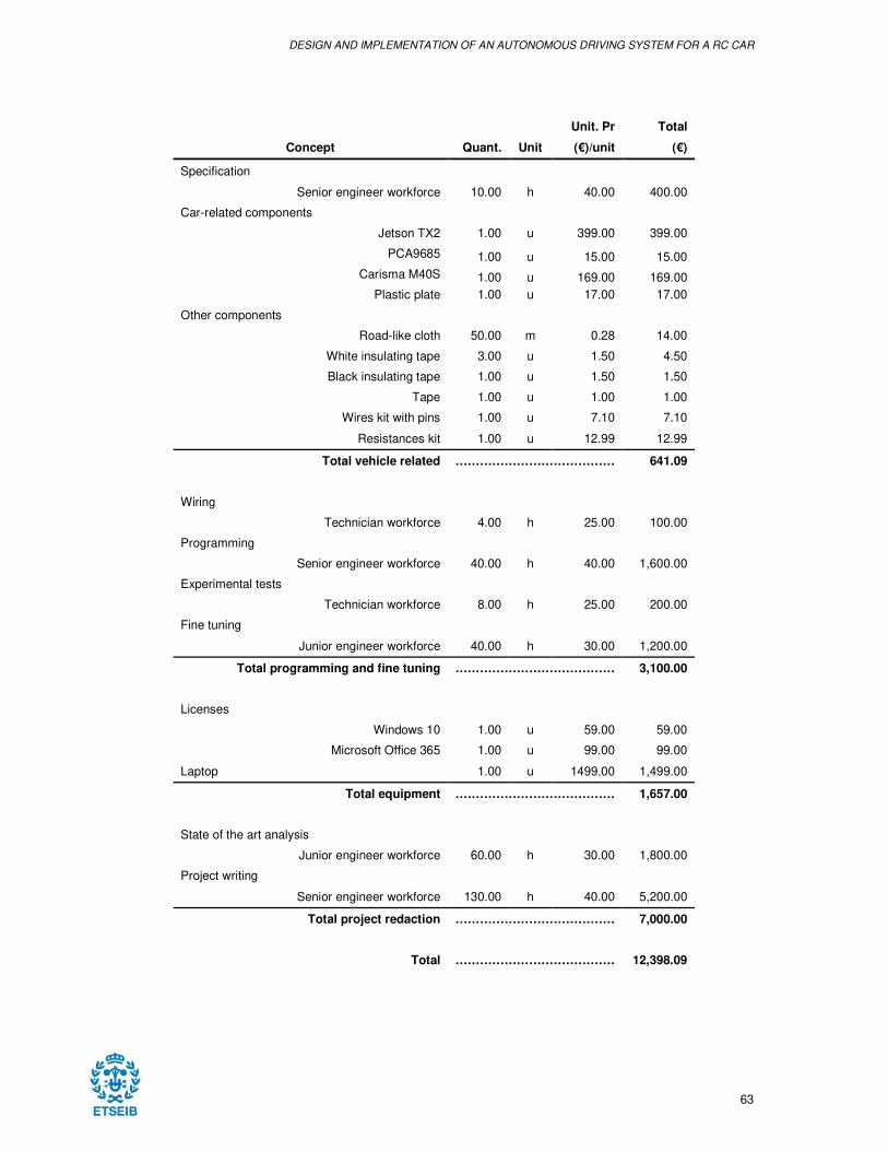
DESIGN AND IMPLEMENTATION OF AN AUTONOMOUS DRIVING SYSTEM FOR A RC CAR
63
Unit. Pr Total
Concept Quant. Unit (€)/unit (€)
Specification
Senior engineer workforce 10.00 h 40.00 400.00
Car-related components Jetson TX2 1.00 u 399.00 399.00
PCA9685 1.00 u 15.00 15.00
Carisma M40S 1.00 u 169.00 169.00
Plastic plate 1.00 u 17.00 17.00
Other components
Road-like cloth 50.00 m 0.28 14.00
White insulating tape 3.00 u 1.50 4.50
Black insulating tape 1.00 u 1.50 1.50
Tape 1.00 u 1.00 1.00
Wires kit with pins 1.00 u 7.10 7.10
Resistances kit 1.00 u 12.99 12.99
Total vehicle related ………………………………… 641.09
Wiring
Technician workforce 4.00 h 25.00 100.00
Programming Senior engineer workforce 40.00 h 40.00 1,600.00
Experimental tests Technician workforce 8.00 h 25.00 200.00
Fine tuning Junior engineer workforce 40.00 h 30.00 1,200.00
Total programming and fine tuning ………………………………… 3,100.00
Licenses Windows 10 1.00 u 59.00 59.00
Microsoft Office 365 1.00 u 99.00 99.00
Laptop 1.00 u 1499.00 1,499.00
Total equipment ………………………………… 1,657.00
State of the art analysis
Junior engineer workforce 60.00 h 30.00 1,800.00
Project writing Senior engineer workforce 130.00 h 40.00 5,200.00
Total project redaction ………………………………… 7,000.00
Total ………………………………… 12,398.09