Design and Fabrication of a Vapor Absorption Refrigeration ...
92
Page | 1 Design and Fabrication of a Vapor Absorption Refrigeration System for Vehicle Cabin Cooling Utilizing Exhaust heat A thesis submitted to Department of Mechanical Engineering in partial fulfillment of the requirements for the degree of Bachelor of Science in Mechanical Engineering Submitted by Student Name Student No. Muhammad Momotazul Islam 201318045 Suvro Bhowmick 201318050 Jabid Ishtiaque 201218035 Supervised by Asst. Professor AM Ishtiaque Mahbub Department of Mechanical Engineering Faculty of Mechanical Engineering Military Institute of Science and Technology (MIST) Mirpur Cantonment, Dhaka, Bangladesh. January 2017
-
Upload
khangminh22 -
Category
Documents
-
view
0 -
download
0
Transcript of Design and Fabrication of a Vapor Absorption Refrigeration ...
P a g e | 1
Design and Fabrication of a Vapor Absorption
Refrigeration System for Vehicle Cabin Cooling
Utilizing Exhaust heat
A thesis submitted to Department of Mechanical Engineering in partial fulfillment of
the requirements for the degree of Bachelor of Science in Mechanical Engineering
Submitted by
Student Name Student No.
Muhammad Momotazul Islam 201318045
Suvro Bhowmick 201318050
Jabid Ishtiaque 201218035
Supervised by
Asst. Professor AM Ishtiaque Mahbub
Department of Mechanical Engineering
Faculty of Mechanical Engineering
Military Institute of Science and Technology (MIST)
Mirpur Cantonment, Dhaka, Bangladesh.
January 2017
P a g e | 2
Declaration
We hereby declare that the work presented in this thesis titled “Design and
Fabrication of a Vapor Absorption Refrigeration System for Vehicle Cabin
Cooling Utilizing Exhaust heat” is an outcome of the investigation carried out by
the authors under the supervision of Asst. Professor AM Ishtiaque Mahbub, MIST.
This paper is made for academic purpose and has not been submitted elsewhere
before for any other objective.
___________________
Muhammad
Momotazul Islam
Student No.
201318045
___________________
Suvro Bhowmick
Student No.
201318050
___________________
Jabid Ishtiaque
Student No.
201218035
P a g e | 3
Certification
The thesis entitled “Design and Fabrication of a Vapor Absorption Refrigeration
System for Vehicle Cabin Cooling Utilizing Exhaust heat” submitted by the group
as mentioned below has been accepted as satisfactory in partial fulfillment of the
requirements for the degree of Bachelor of Science in Mechanical Engineering on
January 2017. This paper embodies original work done under my supervision.
Group members
Student Name Student No.
Muhammad Momotazul Islam 201318045
Suvro Bhowmick 201318050
Jabid Ishtiaque 201218035
Supervisor
AM Ishtiaque Mahbub
Email: [email protected]
Asst. Professor, Faculty of Mechanical Engineering
Military Institute of Science and Technology,
Mirpur Cantonment, Dhaka, Bangladesh
P a g e | 4
Acknowlegdement
At first we thank to Almighty Allah for blessing us the ability to successfully
complete the thesis in due time. We specially thank our thesis supervisor, for his vast
contribution to our thesis. It is only because of his proper guidance and valuable
advice that we managed to complete the thesis. We are extremely greatful and
indebted to him for his support and cooperation throughout the construction process.
We would also like to take this opportunity to thank and express our deepest gratitude
to our instructors who have provided us with valuable advice and cooperation
whenever we faced any problem regarding this thesis. We sincerely thank the
technicians from MIST and outside MIST for their time and cooperation. I also
appreciate my group members for their sincere effort to make this thesis succcessful.
Without their dedications and continuous support it would have been impossible to
build up this model and complete the thesis within a specified time period. Our
fellow classmates have also provided constructive criticism and valuable advice
which helped us a lot. We wish them all the best.
P a g e | 5
Abstract
Automobile air-conditioning is a necessity of present life. Designing energy efficient
and cost effective products are the main challenge in modern world. From that
perspective when we look at a vehicle air conditioning system, it doesn’t fit that
criteria in most of the cases. Vapor compression refrigeration cycle used in modern
automobile uses refrigerant 134-a and the compressor of automobile air-conditioning
is run by engine crankshaft, which reduces the mileage of the automobile. An internal
combustion engine gives about 35% efficiency and when we put the load of air
conditioning, it consumes upto 15-20% energy of the crankshaft. Also 65% heat
energy is wasted through exhaust and cooling system. In many industries waste heat is
used to reutilize in refrigeration system using Vapor Absorption System. The main
theme of this project is to utilize the waste heat of the exhaust gases generated in
internal combustion engines. Before leaving these gases to the atmosphere through the
exhaust necessary mass of exhaust gases is by passed and is made to deliver it
generator so as to run the vapour absorption refrigeration system there by conserving
the energy. We have made the same system in smaller scale so that it can be used in
vehicles and cabin temperature can be kept at a comfortable level. By controlling the
heat provided in generator and pump flow rate we have ensured that the cabin
temperature stays at the thermal comfort zone of 20-25 degree Celcius. In this project
we have used Temperature sensors, Water flow sensor, Pressure gauge, Valves,
Electromagnetic relay and Arduino to monitor the system conditions with time. This
also enables us to control the system completely which wasn’t done in a smaller scale
before. This project takes the idea of using VARS for air cooling one step closer to
industrialization and with continual research this can be developed to use in vehicles
in near future. Owing to the threat of global warming due to high thermal disposal and
to compensate the energy crisis, VARS is likely to gain immense prominence in the
coming years. The aim of the project is to perform analysis on absorption refrigeration
system using lithium-bromide as absorbent and water as refrigerant to find out the
optimal operating temperatures on the thermal loads of components and their co-
efficient of performance. Finally coming up with the operating conditions where it
can run by effectively utilizing the waste heat of the exhaust gases.
P a g e | 6
Table of Contents
Declaration ................................................................................................................................ 2
Certification ............................................................................................................................... 3
Acknowlegdement ..................................................................................................................... 4
Abstract ..................................................................................................................................... 5
Table of Contents ...................................................................................................................... 6
List of Figures: .......................................................................................................................... 9
List of Tables ........................................................................................................................... 10
Chapter One ............................................................................................................................. 11
Introduction ......................................................................................................................... 11
1.1 Background of the study: ................................................................................... 12
1.2 Motivation: ......................................................................................................... 13
1.3 Objective: ........................................................................................................... 14
Chapter Two ............................................................................................................................ 15
Literature review ................................................................................................................. 15
2.1 Introduction ............................................................................................................... 16
2.2 History ....................................................................................................................... 16
2.3. Types of VARS: ....................................................................................................... 17
2.4 Basic Principal of Absorption: .................................................................................. 18
Chapter Three .......................................................................................................................... 24
Theoretical Background ...................................................................................................... 24
3.1 Working fluid for absorption refrigeration system .................................................... 25
3.2 System Description .................................................................................................... 27
3.3 Properties of water-lithium bromide solutions .......................................................... 28
3.4 Practical problems in water-lithium bromide systems............................................... 33
3.5 Utilization of waste heat by LiBr vapor absorption ........................................... 34
3.6 Advantages of VARS ......................................................................................... 35
3.7 Advantages of Lithium bromide -Water over Ammonia-Water ........................ 36
3.8 Disadvantages of VARS..................................................................................... 36
P a g e | 7
Chapter Four ............................................................................................................................ 38
Design consideration ........................................................................................................... 38
4.1 Introduction ........................................................................................................ 39
4.2 Factor affecting the system ................................................................................ 39
4.2.1 Design of Solution Heat Exchanger ................................................................... 39
4.2.2 Design of energy supplying network to the generator ....................................... 39
4.2.3 Design of an water Cooled Condenser ............................................................... 39
4.2.4 Design of Generator and Absorber ..................................................................... 39
4.2.5 Evaporator Design .............................................................................................. 40
4.2.6 Evaporator Design Factors ................................................................................. 40
4.2.7 Capillary Tube .................................................................................................... 41
4.2.8 Safety Measurements with Lithium Bromide .................................................... 41
4.2.9 Condenser size: .................................................................................................. 43
Chapter Five ............................................................................................................................ 45
Design and implementation ................................................................................................. 45
5.1 Equipment required for implementing the design. ........................................................ 46
Major Components: ............................................................................................................. 46
5.1.1 Generator: ........................................................................................................... 46
5.1.2 Condenser ........................................................................................................... 48
5.1.3 Absorber ............................................................................................................. 49
5.1.4 Evaporator .......................................................................................................... 50
5.1.5 Expansion valve: ................................................................................................ 50
5.1.6 DC Pump ............................................................................................................ 51
Auxiliary Components: ....................................................................................................... 52
5.1.7 Temperature sensors: ......................................................................................... 52
5.1.8 Copper Tube ....................................................................................................... 52
5.1.9 Water flow sensor: ............................................................................................. 54
5.1.10 Insulating tape: ................................................................................................... 55
5.1.11 Pipes and Hose Clamp: ...................................................................................... 56

P a g e | 8
5.1.12 Pressure Gauge: .................................................................................................. 56
5.1.13 Nut-Bolts: ........................................................................................................... 57
5.1.14 Arduino Mega: ................................................................................................... 57
5.1.15 Heater: ................................................................................................................ 58
5.1.16 Lithium Bromide Anhydrous: ............................................................................ 59
5.2 Fabrication and assembly: ............................................................................................. 60
5.2.1 Generator ............................................................................................................ 60
5.2.2 Absorber: ............................................................................................................ 62
5.2.3 Condenser:.......................................................................................................... 63
5.2.4 Evaporator and Cabin: ........................................................................................ 63
5.2.5 Frame: ................................................................................................................ 64
Chapter Six .............................................................................................................................. 66
6.2 Calculation ......................................................................................................... 70
6.2.1 Theoretical Calculation: ..................................................................................... 70
6.2.2 Data Table .......................................................................................................... 73
6.2.3 Experimental Calculation: .................................................................................. 74
Chapter Seven .......................................................................................................................... 81
7.1 Result and Observation: ..................................................................................... 82
7.2 Discussion .......................................................................................................... 86
7.3 Application of the system .......................................................................................... 87
7.4 Conclusion ................................................................................................................. 88
7.5 Future Scopes ............................................................................................................ 89
References ................................................................................................................................ 90
Appendix ................................................................................................................................. 92
P a g e | 9
List of Figures:
Figure 1: VARS from 1950s.................................................................................................... 17
Figure 2 : Basic principle of vapor absorption systems ........................................................... 19
Figure 3 : Comparison of Vapor compression (VCRS) and Vapor Absorption refrigeration
system (VARS) ........................................................................................................................ 21
Figure 4 : A continuous absorption refrigeration cycle composes of two processes mentioned
in the earlier figure .................................................................................................................. 25
Figure 5 : LiBr-water vapor absorption system ....................................................................... 27
Figure 6: A typical Dühring plot ............................................................................................. 30
Figure 7: H2O-LiBr system with a solution heat exchanger on Dühring plot ......................... 30
Figure 8: Pressure-Temperature-Concentration diagram for H2O-LiBr solution .................. 31
Figure 9: Enthalpy –Temperature - Concentration diagram for H2O-LiBr solution ............... 32
Figure 10 : distribution of engine heat energy in the system ................................................... 34
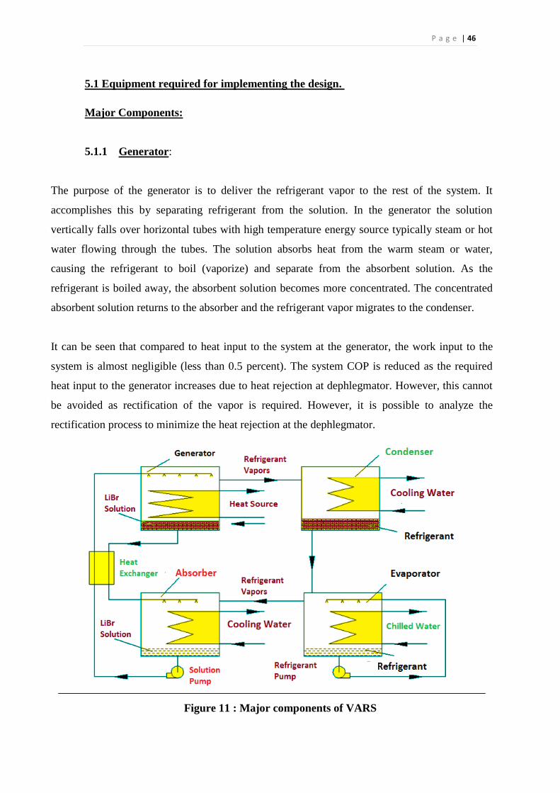
Figure 11 : Major components of VARS ................................................................................ 46
Figure 12: Pressure release valves ........................................................................................... 51
Figure 13: 12V DC Pump ........................................................................................................ 51
Figure 14: Temperature Sensor (LM35) .................................................................................. 52
Figure 15: Copper Tube........................................................................................................... 53
Figure 16: Copper Tube........................................................................................................... 53
Figure 17: Water Flow Sensor (top view) ............................................................................... 55
Figure 18: Water Flow Sensor (isometric view) ..................................................................... 55
Figure 19: Rubber Heat insulation foam tape .......................................................................... 55
Figure 20: Hose clamp ............................................................................................................ 56
Figure 21: Pipes ....................................................................................................................... 56
Figure 22: Pressure gauge ....................................................................................................... 57
Figure 23: Double ended studs and nuts .................................................................................. 57
Figure 24: Arduino mega......................................................................................................... 58
Figure 25: 6KW Water heater ................................................................................................. 59
Figure 26: Lithium Bromide Anhydrous ................................................................................. 59
Figure 27: Generator front view .............................................................................................. 61
Figure 28: Heat insulated generator ........................................................................................ 61
Figure 29 : Generator- Exhaust pipe setup (iso) ...................................................................... 62
Figure 30 : Generator- Exhaust pipe setup (front) ................................................................... 62
Figure 31: Absorber ................................................................................................................. 62
Figure 32: Evaporator cabin .................................................................................................... 63
Figure 33: Arc welded joints ................................................................................................... 64
Figure 34: Final frame after painting ....................................................................................... 64
Figure 35 : Final Setup of VARS ............................................................................................ 65
P a g e | 10
Figure 36: Schematic of LiBr-water system ............................................................................ 67
Figure 37 : Generator Temperature vs COP graph .................................................................. 82
Figure 38 : Evaporator Temperature vs COP graph ................................................................ 83
Figure 39 : Absorber Temperature vs COP graph ................................................................... 83
Figure 40 : Condenser Temperature vs COP graph ................................................................. 84
Figure 41 : Heat transfer Vs Generator temperature graph ..................................................... 84
Figure 42 : Heat transfer vs Evaporator temperature graph .................................................... 85
Figure 43 : Heat transfer vs Absorber temperature graph ....................................................... 85
Figure 44 : Heat transfer vs Condenser temperature graph ..................................................... 86
List of Tables
Table 1 : Materials Used for components and Piping ............................................................. 60
Table 2 : Dimensions of Components ..................................................................................... 65
Table 3 : Data table ................................................................................................................. 73
Table 4 : Calculated values...................................................................................................... 73
Table 5 : Generator Temperature vs COP ............................................................................... 82
Table 6 : Properties of Liquid & Saturated Vapor................................................................... 92
P a g e | 11
Chapter One
Introduction
1.1. Background of the study
1.2. Motivation
1.3. Objective
P a g e | 12
1.1 Background of the study:
In view of shortage of energy production and fast increasing energy consumption,
there is a need to minimize the use of energy and conserve it in all possible ways.
Energy conservation (i.e. energy saved is more desirable than energy produced) is
becoming a slogan of the present decade and new methods to save energy, otherwise
being wasted, are being explored. Recovering energy from waste heat and/or
utilizing it for system efficiency improvement is fast becoming a common scientific
temper and industrial practice nowadays. The present energy crisis has forced the
scientists and engineers all over the world to adopt energy conservation measures in
various industries. Reduction of the electric power and thermal energy consumption
are not only desirable but unavoidable in view of fast and competitive industrial
growth throughout the world. Refrigeration systems form a vital component for the
industrial growth and affect the energy problems of the country at large. Therefore, it
is desirable to provide a base for energy conservation and energy recovery from
Vapor Absorption System. Although, the investigations undertaken in this Work are
of applied research nature but certainly can create a base for further R & D activities
in the direction of energy conservation and heat recovery options for refrigeration
systems and the analysis can be extended further to other Refrigeration and Air
Conditioning Systems. In recent years, research has been devoted to improvement of
Absorption Refrigeration Systems (ARSs). However, ARS’s harmless inexpensive
waste heat, solar, biomass or geothermal energy sources for which the cost of supply
is negligible in many cases. Moreover, the Working fluids of these systems are
environmentally friendly .The overall performance of the absorption cycle in terms
of refrigerating effect per unit of energy input generally poor, however, waste heat
such as that rejected from a power can be used to achieve better overall energy
utilization. Ammonia/water (NH3/H2O) systems are widely used where lower
temperature is required. However, Water/lithium bromide (H20/LiBr) systems are
also widely used where moderate temperatures are required (e.g. air conditioning).
P a g e | 13
1.2 Motivation:
With considering AC system of conventional automobile, powered by internal
combustion engine is utilized the engine developed power to drive the compressor.
This may take around 15 to 20% of engine power to drive the piston or rotary
compressor. Approximately it consumes of 20% total fuel consumption on the other
hand the R12 used as refrigerant (Or R134a) and it is affected to ozone layer depletion.
However many passenger vehicle engine utilizes only about 35% of total energy and
rests are lost to various form of energy losses. If one is adding conventional air
conditioning system to automobile, it further utilizes about 15% to 20% of the total
energy. Therefore most of existing automobile becomes uneconomical and less
efficient. In addition conventional air conditioner is causes to decreases the life time of
engine also. Hence considering of the above factors in this research introduce an
alternative solution for automobiles AC system as based on absorption refrigeration
cycle using exhaust waste heat of the engine.
The advantages of this system over conventional air-conditioning system are that, it
does not affect original design of the whole system. But overall fuel consumption of
engine significant amount reduction & therefore, the running of the engine efficiently
and economically. On the other hand it showed comparatively less environmental
pollution.
Furthermore life time of engine optimized due to less load capacity of engine. Another
difference between absorption systems and conventional vapor compression systems is
the working fluid used. Most vapor compression systems commonly use
chlorofluorocarbon refrigerants (CFC s), because of their thermophysical properties. It
is through the restricted use of CFC s, due to depletion of the ozone layer that will
make absorption systems more prominent.

P a g e | 14
1.3 Objective:
The objective of this work is to develop a refrigeration system which will provide the
cooling effect that is cheaper & energy saver than the existing refrigeration system.
As it has no moving parts, its maintenance & repair cost is less.
Vapor compression refrigeration system uses mechanical energy from engine
whereas vapor absorption refrigeration system uses waste heat or renewable energy.
Its objective is to ensure that countries like Bangladesh where energy shortage is a
great problem can get the benefit of this refrigeration system.
Preservation of foods, fruits & other things that need cold storing during summer
season while traveling will be easier by using this VAR system.
It can also be used to cool the space inside a car by utilizing waste heat & exhaust
gases from engine.
To develop a refrigeration system that will not produce any greenhouse gases.
To provide cabin cooling in the passenger vehicle by minimizing temperature few
degrees from atmospheric temperature.
P a g e | 15
Chapter Two
Literature review
2.1. Introduction
2.2. History
2.3. Types of VARS
2.4. Basic Principal of Absorption
P a g e | 16
2.1 Introduction
Widespread efforts are currently underway to utilize available energy resources efficiently by
minimizing waste energy and develop replacements for the traditionally refrigerants (CFCs and
HCFCs), which contribute to ozone depletion and greenhouse warming. Absorption chillers
which are heat-powered refrigeration systems have got more and more attention, due to the
recognition of rational utilization of energy and the concerns about ecological problem. Vapor
Absorption Refrigeration Systems (VARS) belong to the class of vapor cycles similar to vapor
compression refrigeration systems. However, unlike vapor compression refrigeration systems,
the required input to absorption systems is in the form of heat. Hence these systems are also
called as heat operated or thermal energy driven systems. Since conventional absorption systems
use liquids for absorption of refrigerant, these are also sometimes called as wet absorption
systems. Similar to vapor compression refrigeration systems, vapor absorption refrigeration
systems have also been commercialized and are widely used in various refrigeration and air
conditioning applications. Since these systems run on low-grade thermal energy, they are
preferred when low-grade energy such as waste heat or solar energy is available. Since
conventional absorption systems use natural refrigerants such as water or ammonia they are
environment friendly.
2.2 History
The early development of an absorption cycle dates back to the 1700’s. It was known that ice
could be produced by an evaporation of pure water from a vessel contained within an evacuated
container in the presence of sulfuric acid.
In 1810, ice could be made from water in a vessel, which was connected to another vessel
containing sulfuric acid. As the acid absorbed water vapor, causing a reduction of temperature,
layers of ice were formed on the water surface. The major problems of this system were
corrosion and leakage of air into the vacuum vessel. In 1859, Ferdinand Carre introduced a novel
machine using water/ammonia as the fluid. This machine took out a US patent in 1860. Machines
based on this patent were used to make ice and store food. It was used as a basic design in the
early age of refrigeration development.
P a g e | 17
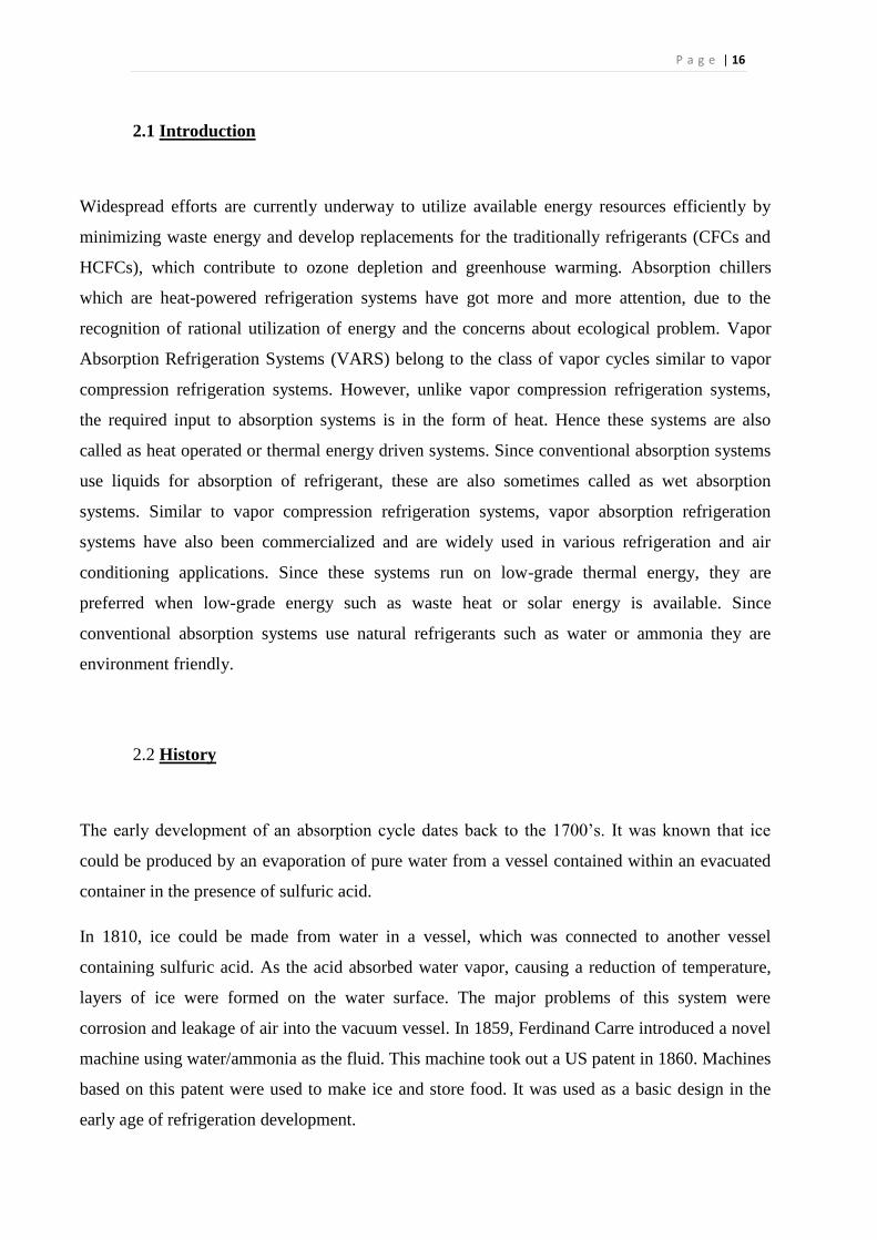
Figure 1: VARS from 1950s
In the 1950’s, a system using lithium bromide/water as the working fluid was introduced
for industrial applications. A few years later, a double-effect absorption system was
introduced and has been used as an industrial standard for a high performance heat-
operated refrigeration cycle.
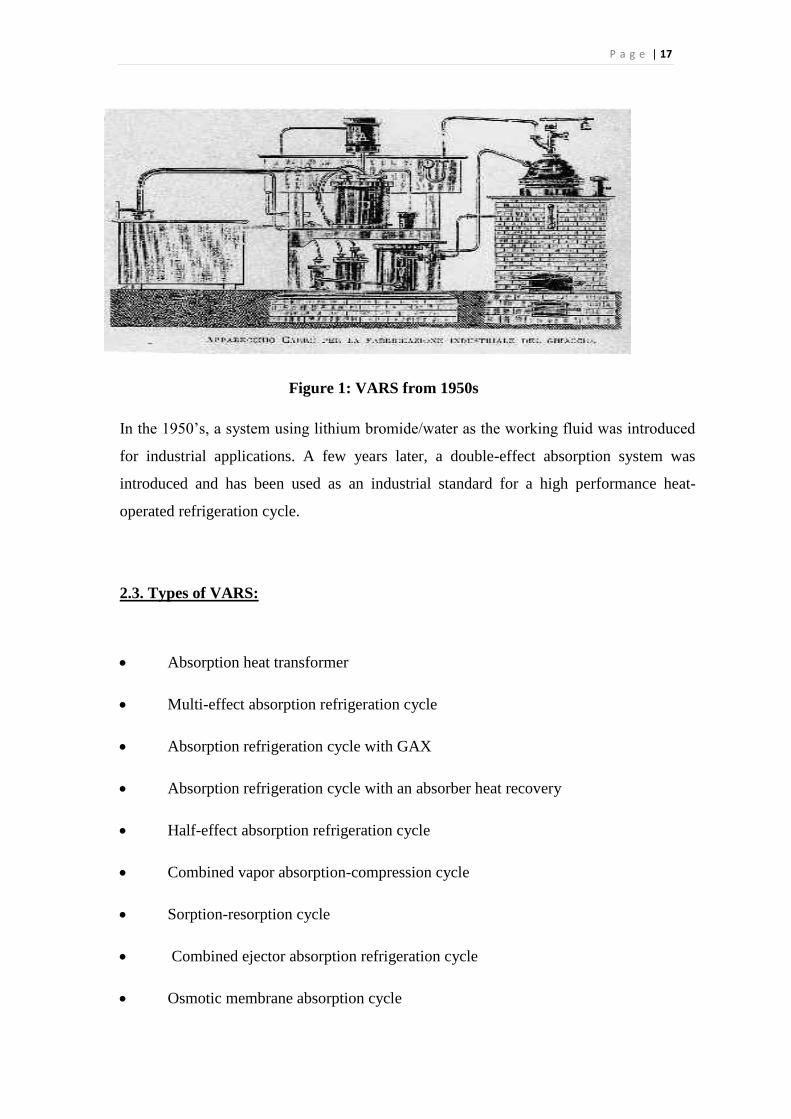
2.3. Types of VARS:
Absorption heat transformer
Multi-effect absorption refrigeration cycle
Absorption refrigeration cycle with GAX
Absorption refrigeration cycle with an absorber heat recovery
Half-effect absorption refrigeration cycle
Combined vapor absorption-compression cycle
Sorption-resorption cycle
Combined ejector absorption refrigeration cycle
Osmotic membrane absorption cycle
P a g e | 18
Self-circulation absorption system using LiBr/water
2.4 Basic Principal of Absorption:
When a solute such as lithium bromide salt is dissolved in a solvent such as water, the boiling
point of the solvent (water) is elevated. On the other hand, if the temperature of the solution
(solvent + solute) is held constant, then the effect of dissolving the solute is to reduce the vapor
pressure of the solvent below that of the saturation pressure of pure solvent at that temperature. If
the solute itself has some vapor pressure (i.e., volatile solute) then the total pressure exerted over
the solution is the sum total of the partial pressures of solute and solvent. If the solute is non-
volatile (e.g. lithium bromide salt) or if the boiling point difference between the solution and
solvent is large (≥ 300oC), then the total pressure exerted over the solution will be almost equal
to the vapor pressure of the solvent only. In the simplest absorption refrigeration system,
refrigeration is obtained by connecting two vessels, with one vessel containing pure solvent and
the other containing a solution.
Since the pressure is almost equal in both the vessels at equilibrium, the temperature of the
solution will be higher than that of the pure solvent. This means that if the solution is at ambient
temperature, then the pure solvent will be at a temperature lower than the ambient. Hence
refrigeration effect is produced at the vessel containing pure solvent due to this temperature
difference. The solvent evaporates due to heat transfer from the surroundings, flows to the vessel
containing solution and is absorbed by the solution. This process is continued as long as the
composition and temperature of the solution are maintained and liquid solvent is available in the
container.
For example, Fig 2.4.1 shows an arrangement, which consists of two vessels A and B connected
to each other through a connecting pipe and a valve. Vessel A is filled with pure water, while
vessel B is filled with a solution containing on mass basis 50 percent of water and 50 percent
lithium bromide (LiBr salt). Initially the valve connecting these two vessels is closed, and both
vessels are at thermal equilibrium with the surroundings, which is at 30o C. At 30
oC, the
saturation pressure of water is 4.24 kPa, and the equilibrium vapor pressure of water-lithium
bromide solution (50: 50 by mass) at 30oC is 1.22 kPa.
P a g e | 19
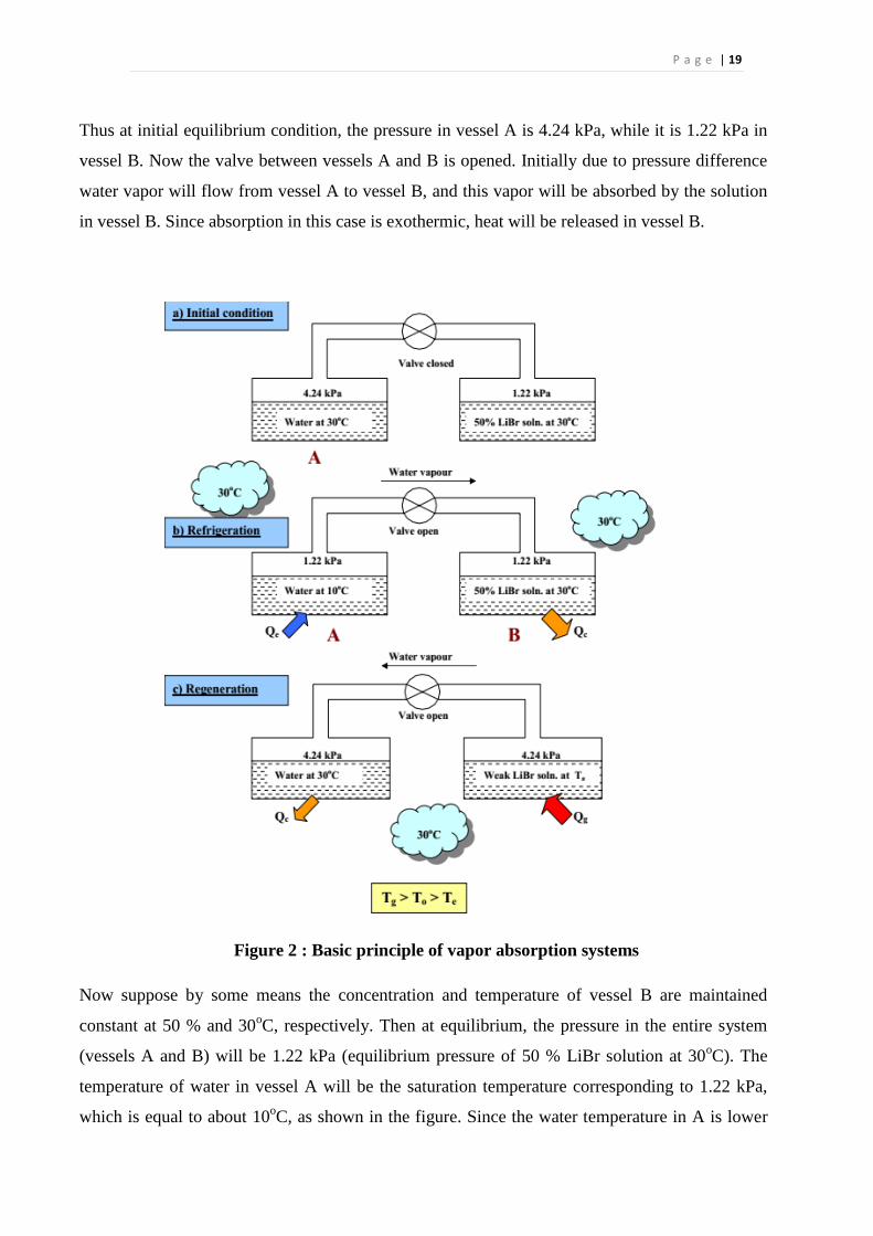
Thus at initial equilibrium condition, the pressure in vessel A is 4.24 kPa, while it is 1.22 kPa in
vessel B. Now the valve between vessels A and B is opened. Initially due to pressure difference
water vapor will flow from vessel A to vessel B, and this vapor will be absorbed by the solution
in vessel B. Since absorption in this case is exothermic, heat will be released in vessel B.
Figure 2 : Basic principle of vapor absorption systems
Now suppose by some means the concentration and temperature of vessel B are maintained
constant at 50 % and 30oC, respectively. Then at equilibrium, the pressure in the entire system
(vessels A and B) will be 1.22 kPa (equilibrium pressure of 50 % LiBr solution at 30oC). The
temperature of water in vessel A will be the saturation temperature corresponding to 1.22 kPa,
which is equal to about 10oC, as shown in the figure. Since the water temperature in A is lower
P a g e | 20
than the surroundings, a refrigeration effect (Qe) can produced by transferring heat from the
surroundings to water at 10oC.
Due to this heat transfer, water vaporizes in A, flows to B and is absorbed by the solution in B.
The exothermic heat of absorption (Qa) is rejected to the surroundings.
Now for the above process to continue there should always be pure water in vessel A and vessel
B must be maintained always at 50 percent concentration and 30oC. This is not possible in a
closed system such as the one shown in Fig 2. In a closed system with finite sized reservoirs,
gradually the amount of water in A decreases and the solution in B becomes diluted with water.
As a result, the system pressure and temperature of water in A increase with time. Hence the
refrigeration effect at A reduces gradually due to the reduced temperature difference between the
surroundings and water. Thus refrigeration produced by systems using only two vessels is
intermittent in nature. In these systems, after a period, the refrigeration process has to be stopped
and both the vessels A and B have to be brought back to their original condition. This requires
removal of water absorbed in B and adding it back to vessel A in liquid form, i.e., a process of
regeneration as shown in Fig.2(c).
Assume that before regeneration is carried out, the valve between A and B is closed and both A
and B are brought in thermal equilibrium with the surroundings (30oC), then during the
regeneration process, heat at high temperature Tg is supplied to the dilute LiBr solution in B, as a
result water vapor is generated in B. The vapor generated in B is condensed into pure water in A
by rejecting heat of condensation to the surroundings. This process has to be continued till all the
water absorbed during the refrigeration process (2(b)) is transferred back to A. Then to bring the
system back to its original condition, the valve has to be closed and solution in vessel B has to be
cooled to 30oC. If we assume a steady-flow process of regeneration and neglect temperature
difference for heat transfer, then the temperature of water in A will be 30oC and pressure inside
the system will be 4.24 kPa. Then the temperature in vessel B, Tg depends on the concentration
of solution in B. The amount of heat transferred during refrigeration and regeneration depends on
the properties of solution and the operating conditions. It can be seen that the output from this
system is the refrigeration obtained Qe and the input is heat supplied to vessel B during vapour
regeneration process, Qg.
P a g e | 21
The system described may be called as an Intermittent Absorption Refrigeration System. The
solvent is the refrigerant and the solute is called as absorbent. These simple systems can be used
to provide refrigeration using renewable energy such as solar energy in remote and rural areas.
As already explained, these systems provided refrigeration intermittently, if solar energy is used
for regenerating the refrigerant, then regeneration process can be carried out during the day and
refrigeration can be produced during the night.
Though the intermittent absorption refrigeration systems discussed above are simple in design
and inexpensive, they are not useful in applications that require continuous refrigeration.
Continuous refrigeration can be obtained by having a modified system with two pairs of vessels
A and B and additional expansion valves and a solution pump.
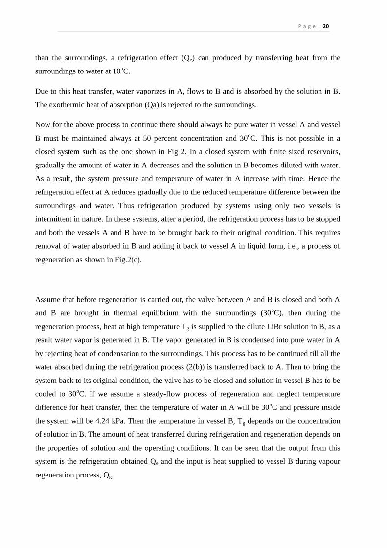
Figure 3 : Comparison of Vapor compression (VCRS) and Vapor Absorption
refrigeration system (VARS)
Figure 3 (a) and (b) show a continuous output vapor compression refrigeration system and a
continuous output vapor absorption refrigeration system. As shown in the figure in a continuous
absorption system, low temperature and low pressure refrigerant with low quality enters the
P a g e | 22
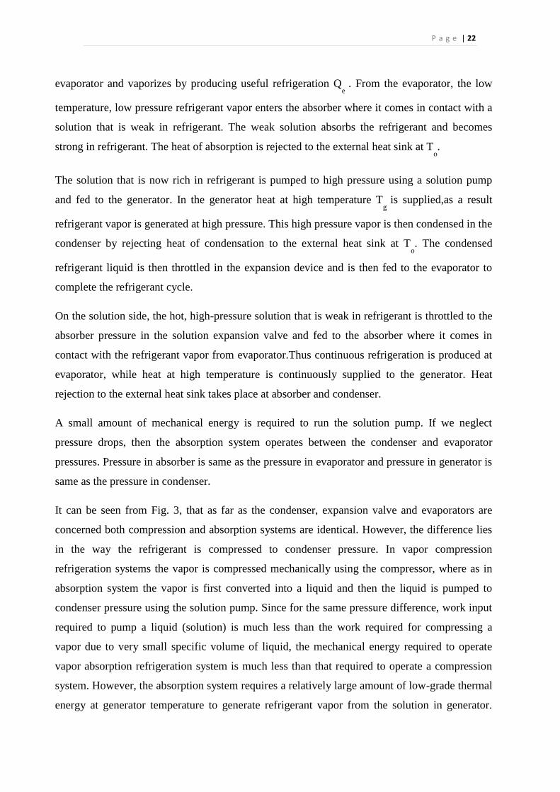
evaporator and vaporizes by producing useful refrigeration Qe
. From the evaporator, the low
temperature, low pressure refrigerant vapor enters the absorber where it comes in contact with a
solution that is weak in refrigerant. The weak solution absorbs the refrigerant and becomes
strong in refrigerant. The heat of absorption is rejected to the external heat sink at To.
The solution that is now rich in refrigerant is pumped to high pressure using a solution pump
and fed to the generator. In the generator heat at high temperature Tg
is supplied,as a result
refrigerant vapor is generated at high pressure. This high pressure vapor is then condensed in the
condenser by rejecting heat of condensation to the external heat sink at To. The condensed
refrigerant liquid is then throttled in the expansion device and is then fed to the evaporator to
complete the refrigerant cycle.
On the solution side, the hot, high-pressure solution that is weak in refrigerant is throttled to the
absorber pressure in the solution expansion valve and fed to the absorber where it comes in
contact with the refrigerant vapor from evaporator.Thus continuous refrigeration is produced at
evaporator, while heat at high temperature is continuously supplied to the generator. Heat
rejection to the external heat sink takes place at absorber and condenser.
A small amount of mechanical energy is required to run the solution pump. If we neglect
pressure drops, then the absorption system operates between the condenser and evaporator
pressures. Pressure in absorber is same as the pressure in evaporator and pressure in generator is
same as the pressure in condenser.
It can be seen from Fig. 3, that as far as the condenser, expansion valve and evaporators are
concerned both compression and absorption systems are identical. However, the difference lies
in the way the refrigerant is compressed to condenser pressure. In vapor compression
refrigeration systems the vapor is compressed mechanically using the compressor, where as in
absorption system the vapor is first converted into a liquid and then the liquid is pumped to
condenser pressure using the solution pump. Since for the same pressure difference, work input
required to pump a liquid (solution) is much less than the work required for compressing a
vapor due to very small specific volume of liquid, the mechanical energy required to operate
vapor absorption refrigeration system is much less than that required to operate a compression
system. However, the absorption system requires a relatively large amount of low-grade thermal
energy at generator temperature to generate refrigerant vapor from the solution in generator.
P a g e | 23
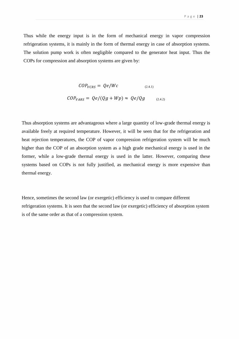
Thus while the energy input is in the form of mechanical energy in vapor compression
refrigeration systems, it is mainly in the form of thermal energy in case of absorption systems.
The solution pump work is often negligible compared to the generator heat input. Thus the
COPs for compression and absorption systems are given by:
𝐶𝑂𝑃𝑉𝐶𝑅𝑆 = 𝑄𝑒/𝑊𝑐 (2.4.1)
𝐶𝑂𝑃𝑉𝐴𝑅𝑆 = 𝑄𝑒/(𝑄𝑔 + 𝑊𝑝) ≈ 𝑄𝑒/𝑄𝑔 (2.4.2)
Thus absorption systems are advantageous where a large quantity of low-grade thermal energy is
available freely at required temperature. However, it will be seen that for the refrigeration and
heat rejection temperatures, the COP of vapor compression refrigeration system will be much
higher than the COP of an absorption system as a high grade mechanical energy is used in the
former, while a low-grade thermal energy is used in the latter. However, comparing these
systems based on COPs is not fully justified, as mechanical energy is more expensive than
thermal energy.
Hence, sometimes the second law (or exergetic) efficiency is used to compare different
refrigeration systems. It is seen that the second law (or exergetic) efficiency of absorption system
is of the same order as that of a compression system.
P a g e | 24
Chapter Three
Theoretical Background
3.1. Working fluid for absorption refrigeration system
3.2. System description
3.3. Properties of water-lithium bromide solutions
3.4. Practical problems in water-lithium bromide system
3.5. Utilization of waste heat by Water-Lithium Bromide Based vapor absorption system
3.6. Advantages of VARS
3.7. Advantages of Lithium bromide-Water over Ammonia-Water
3.8. Disadvantages of VARS
P a g e | 25
3.1 Working fluid for absorption refrigeration system
Performance of an absorption refrigeration system is critically dependent on the chemical and
thermodynamic properties of the working fluid. A fundamental requirement of
absorbent/refrigerant combination is that, in liquid phase, they must have a margin of miscibility
within the operating temperature range of the cycle. The mixture should also be chemically
stable, non-toxic, and non-explosive. In addition to these requirements, the following are
desirable.
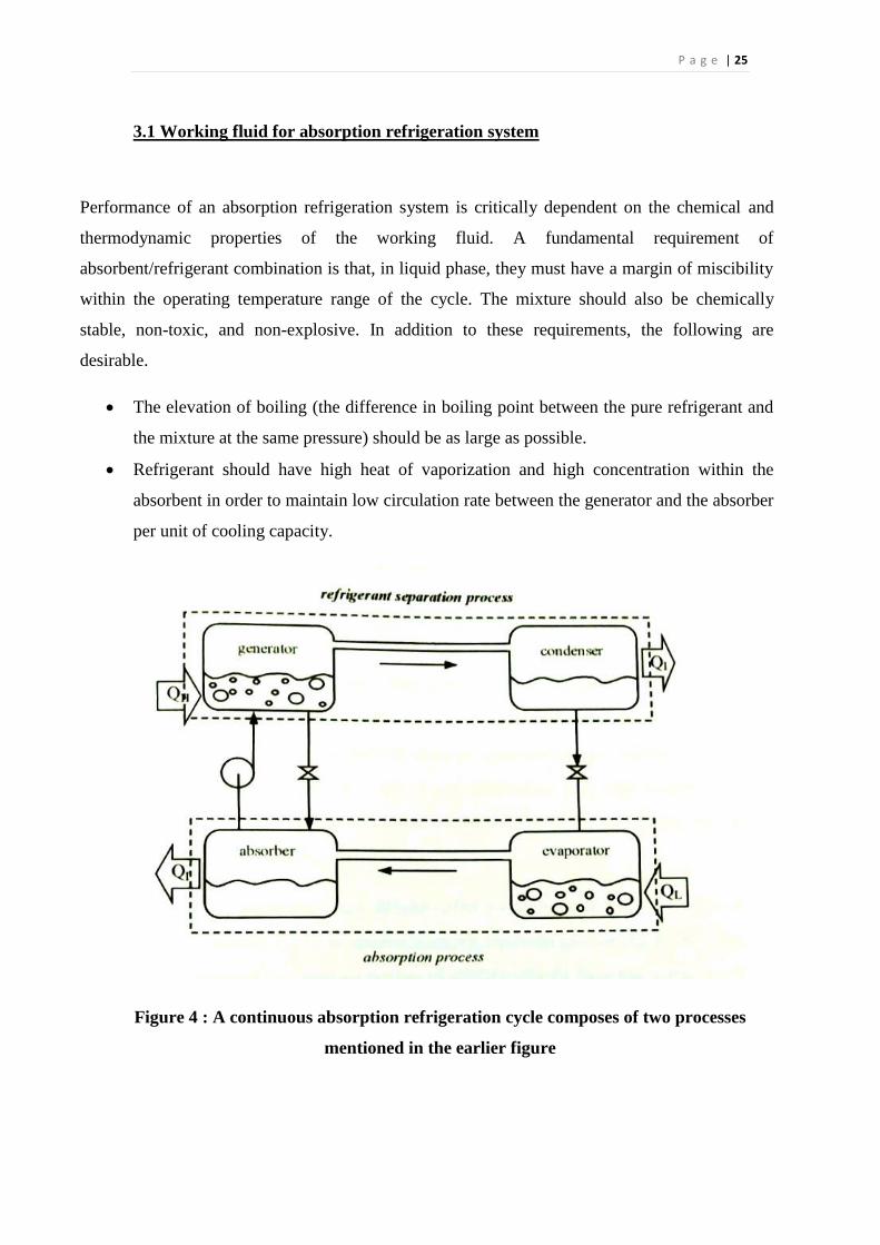
The elevation of boiling (the difference in boiling point between the pure refrigerant and
the mixture at the same pressure) should be as large as possible.
Refrigerant should have high heat of vaporization and high concentration within the
absorbent in order to maintain low circulation rate between the generator and the absorber
per unit of cooling capacity.
Figure 4 : A continuous absorption refrigeration cycle composes of two processes
mentioned in the earlier figure
P a g e | 26
Transport properties that inexhaustnce heat and mass transfer, e.g., viscosity, thermal
conductivity, and diffusion coefficient should be favorable.
Both refrigerant and absorbent should be non-corrosive, environmental friendly and low-
cost.
Many working fluids are suggested in literature. A survey of absorption fluids provided by
Marcriss suggests that, there are some 40 refrigerant compounds and 200 absorbent compounds
available. However, the most common working fluids are Water/NH3 and LiBr/water.
Since the invention of an absorption refrigeration system, water NH3 has been widely used for
both cooling and heating purposes. Both NH3(refrigerant) and water (absorbent) are highly stable
for a wide range of operating temperature and pressure. NH3 has a high latent heat of
vaporization, which is necessary for efficient performance of the system. It can be used for low
temperature applications, as the freezing point of NH3 is 77 degree centigrade. Since both NH3
and water are volatile, the cycle requires a rectifier to strip away water that normally evaporates
with NH3. Without a rectifier, the water would accumulate in the evaporator and offset the
system performance.
The use of LiBr-water for absorption refrigeration systems began around 1930.Two outstanding
features of LiBr-water are non-volatility absorbent of LiBr (the need of a rectifier is eliminated)
and extremely high heat of vaporization of water (refrigerant). However, using water as a
refrigerant limits the low temperature application to that above 0 degree centigrade. As water is
the refrigerant, the system must be operated under vacuum conditions. At high concentrations,
the solution is prone to crystallization. It is also corrosive to some metal and expensive. Some
additive may be added to LiBr-water as a corrosion inhibitor or to improve heat mass transfer
performance.
Although LiBr-water and water/NH3 have been widely used for many years and their properties
are well known, much extensive research has been carried out to investigate new working fluids.
Fluorocarbon refrigerant based working fluids have been studied. R22 and R21 have been widely
suggested because of their favorable solubility with number of organic solvents. The two
solvents, which have stood out are Dimethyl Ether of Tetraethylene Glycol (DMETEG) and
Dimethyl Formamide (DMF).
A binary mixture using inorganic salt absorbent such as LiBr-water or NaOH-water may be the
most successful working for an absorption refrigeration system. However, at high concentration
P a g e | 27
such as at high temperature, the solution is prone to crystallization. It was found that the addition
of a second salt as in a ternary mixture such as LiBr+ZnBr2/water can improve the solubility of
the solution. Various ternary mixtures have been tested for using with an absorption system.
Though there are many refrigerants and absorbents which can be used in a vapor absorption
refrigeration system we are using LiBr-Water solution in this project we are using water as
refrigerant and Lithium bromide as absorbent.
3.2 System Description
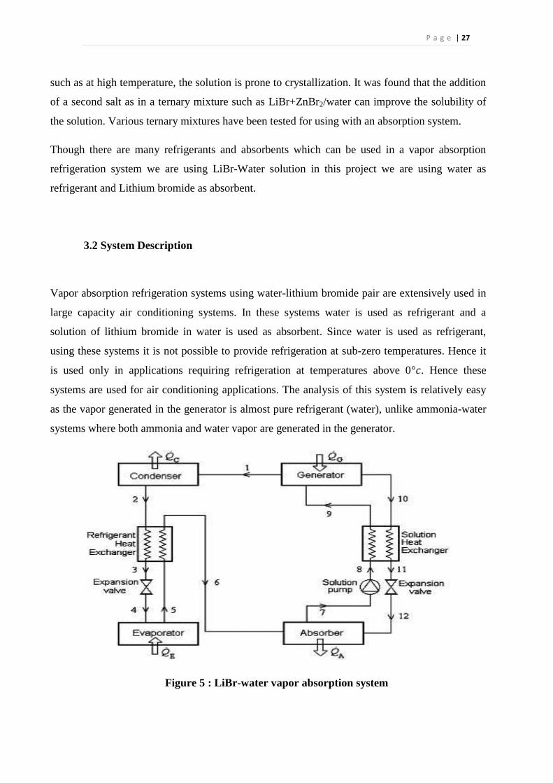
Vapor absorption refrigeration systems using water-lithium bromide pair are extensively used in
large capacity air conditioning systems. In these systems water is used as refrigerant and a
solution of lithium bromide in water is used as absorbent. Since water is used as refrigerant,
using these systems it is not possible to provide refrigeration at sub-zero temperatures. Hence it
is used only in applications requiring refrigeration at temperatures above 0°𝑐. Hence these
systems are used for air conditioning applications. The analysis of this system is relatively easy
as the vapor generated in the generator is almost pure refrigerant (water), unlike ammonia-water
systems where both ammonia and water vapor are generated in the generator.
Figure 5 : LiBr-water vapor absorption system
P a g e | 28
Process 5-6-7. The water vapors from the evaporator pass through absorber. Strong Lithium
bromide solution is spread on this water vapor. . This makes the solution weak.
Process 7-8-9-1 The solution is pumped to Generator passing through a heat exchanger. . This
solution is now heated to disperse weak and Strong lithium bromide solutions. . The additional
heat supply is done in Generator.
Process 10-11-12 the strong Solution is processed through a heat exchanger and expansion valve
to absorber. This solution is sprayed on the water vapor coming from evaporator.
Process 1-2-3 The weak solution is passed through Condenser where it is cooled and condensed.
The refrigerant heat exchanger loses some more heat to the vapor passing to absorber.
Process 3-4-5 The condensed solution is passed through expansion device resulting in high
pressure drop. . This low pressure solution absorbs heat from the material in order to vaporize.
This vapor is again fed as in process 5-6-7.
3.3 Properties of water-lithium bromide solutions
3.3.1 Composition:
The composition of water-lithium bromide solutions can be expressed either in mass fraction (ξ)
or mole fraction (x). For water-lithium bromide solutions, the mass fraction ξ is defined as the
ratio of mass of anhydrous lithium bromide to the total mass of solution, i.e.
𝜉=𝑚L/(𝑚L+𝑚W) (3.3.1a)
Where mLand m
W is the mass of anhydrous lithium bromide and water in solution, respectively.
The composition can also be expressed in terms of mole fraction of lithium bromide as:
𝑋= 𝑛L/ (𝑛L+𝑛W) (3.3.1b)
P a g e | 29
where nL
and nW
are the number of moles of anhydrous lithium bromide and water in solution,
respectively. The number moles of lithium bromide and water can easily be obtained from their
respective masses in solution and molecular weights, thus;
𝑛L=𝑚L/𝑀L and 𝑛W=𝑚W/𝑀W (3.3.1c)
where ML
(= 86.8 kg/kmol) and MW
(= 18.0 kg/kmol) are the molecular weights of anhydrous
lithium bromide and water respectively.
3.3.2 Vapor pressure of water-lithium bromide solutions
Applying Raoult’s law, the vapor pressure of water-lithium bromide solution with the vapor
pressure exerted by lithium bromide being negligibly small is given by:
𝑃 = (1-𝑥)𝑃W
where PW
is the saturation pressure of pure water at the same temperature as that of the solution
and x is the mole fraction of lithium bromide in solution. It is observed that Raoult’s law is only
approximately correct for very dilute solutions of water lithium bromide (i.e., as x → 0). Strong
aqueous solutions of water-lithium bromide are found to deviate strongly from Raoult’s law in a
negative manner.
For example, at 50 percent mass fraction of lithium bromide and 25o
C, Raoult’s law predicts a
vapor pressure of 26.2 mbar, whereas actual measurements show that it is only 8.5 mbar.
The ratio of actual vapor pressure to that predicted by Raoult’s law is known as activity
coefficient. For the above example, the activity coefficient is 0.324.
The vapor pressure data of water-lithium bromide solutions can be very conveniently represented
in a Dühring plot. In a Dühring plot, the temperature of the solution is plotted as abscissa on a
linear scale, the saturation temperature of pure water is plotted as ordinate on the right hand side
(linear scale) and the pressure on a logarithmic scale is plotted as ordinate on the left hand side.
The plot shows the pressure-temperature values for various constant concentration lines
(isosters), which are linear on Dühring plot. Figures 15.1 show the Dühring plot. The Dühring
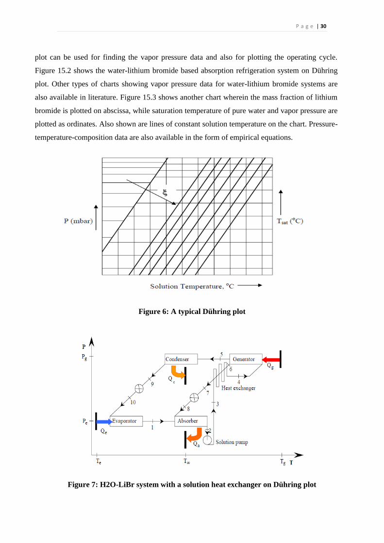
P a g e | 30
plot can be used for finding the vapor pressure data and also for plotting the operating cycle.
Figure 15.2 shows the water-lithium bromide based absorption refrigeration system on Dühring
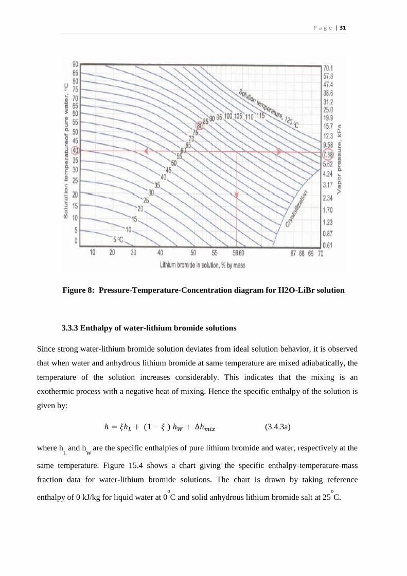
plot. Other types of charts showing vapor pressure data for water-lithium bromide systems are
also available in literature. Figure 15.3 shows another chart wherein the mass fraction of lithium
bromide is plotted on abscissa, while saturation temperature of pure water and vapor pressure are
plotted as ordinates. Also shown are lines of constant solution temperature on the chart. Pressure-
temperature-composition data are also available in the form of empirical equations.
Figure 6: A typical Dühring plot
Figure 7: H2O-LiBr system with a solution heat exchanger on Dühring plot
P a g e | 31
Figure 8: Pressure-Temperature-Concentration diagram for H2O-LiBr solution
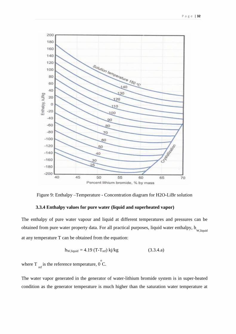
3.3.3 Enthalpy of water-lithium bromide solutions
Since strong water-lithium bromide solution deviates from ideal solution behavior, it is observed
that when water and anhydrous lithium bromide at same temperature are mixed adiabatically, the
temperature of the solution increases considerably. This indicates that the mixing is an
exothermic process with a negative heat of mixing. Hence the specific enthalpy of the solution is
given by:
ℎ = 𝜉ℎ𝐿 + (1 − 𝜉 ) ℎ𝑊 + ∆ℎ𝑚𝑖𝑥 (3.4.3a)
where hL
and hW
are the specific enthalpies of pure lithium bromide and water, respectively at the
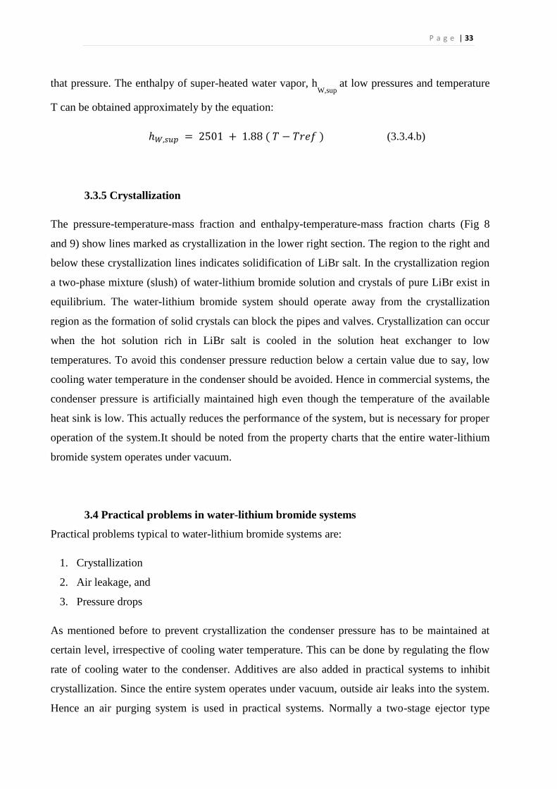
same temperature. Figure 15.4 shows a chart giving the specific enthalpy-temperature-mass
fraction data for water-lithium bromide solutions. The chart is drawn by taking reference
enthalpy of 0 kJ/kg for liquid water at 0o
C and solid anhydrous lithium bromide salt at 25o
C.
P a g e | 32
Figure 9: Enthalpy –Temperature - Concentration diagram for H2O-LiBr solution
3.3.4 Enthalpy values for pure water (liquid and superheated vapor)
The enthalpy of pure water vapour and liquid at different temperatures and pressures can be
obtained from pure water property data. For all practical purposes, liquid water enthalpy, hW,liquid
at any temperature T can be obtained from the equation:
hW,liquid = 4.19 (T-Tref) kj/kg (3.3.4.a)
where T ref
is the reference temperature, 0o
C.
The water vapor generated in the generator of water-lithium bromide system is in super-heated
condition as the generator temperature is much higher than the saturation water temperature at
P a g e | 33
that pressure. The enthalpy of super-heated water vapor, hW,sup
at low pressures and temperature
T can be obtained approximately by the equation:
ℎ𝑊,𝑠𝑢𝑝 = 2501 + 1.88 ( 𝑇 − 𝑇𝑟𝑒𝑓 ) (3.3.4.b)
3.3.5 Crystallization
The pressure-temperature-mass fraction and enthalpy-temperature-mass fraction charts (Fig 8
and 9) show lines marked as crystallization in the lower right section. The region to the right and
below these crystallization lines indicates solidification of LiBr salt. In the crystallization region
a two-phase mixture (slush) of water-lithium bromide solution and crystals of pure LiBr exist in
equilibrium. The water-lithium bromide system should operate away from the crystallization
region as the formation of solid crystals can block the pipes and valves. Crystallization can occur
when the hot solution rich in LiBr salt is cooled in the solution heat exchanger to low
temperatures. To avoid this condenser pressure reduction below a certain value due to say, low
cooling water temperature in the condenser should be avoided. Hence in commercial systems, the
condenser pressure is artificially maintained high even though the temperature of the available
heat sink is low. This actually reduces the performance of the system, but is necessary for proper
operation of the system.It should be noted from the property charts that the entire water-lithium
bromide system operates under vacuum.
3.4 Practical problems in water-lithium bromide systems
Practical problems typical to water-lithium bromide systems are:
1. Crystallization
2. Air leakage, and
3. Pressure drops
As mentioned before to prevent crystallization the condenser pressure has to be maintained at
certain level, irrespective of cooling water temperature. This can be done by regulating the flow
rate of cooling water to the condenser. Additives are also added in practical systems to inhibit
crystallization. Since the entire system operates under vacuum, outside air leaks into the system.
Hence an air purging system is used in practical systems. Normally a two-stage ejector type
P a g e | 34
purging system is used to remove air from the system. Since the operating pressures are very
small and specific volume of vapor is very high, pressure drops due to friction should be
minimized. This is done by using twin- and single-drum arrangements in commercial systems.
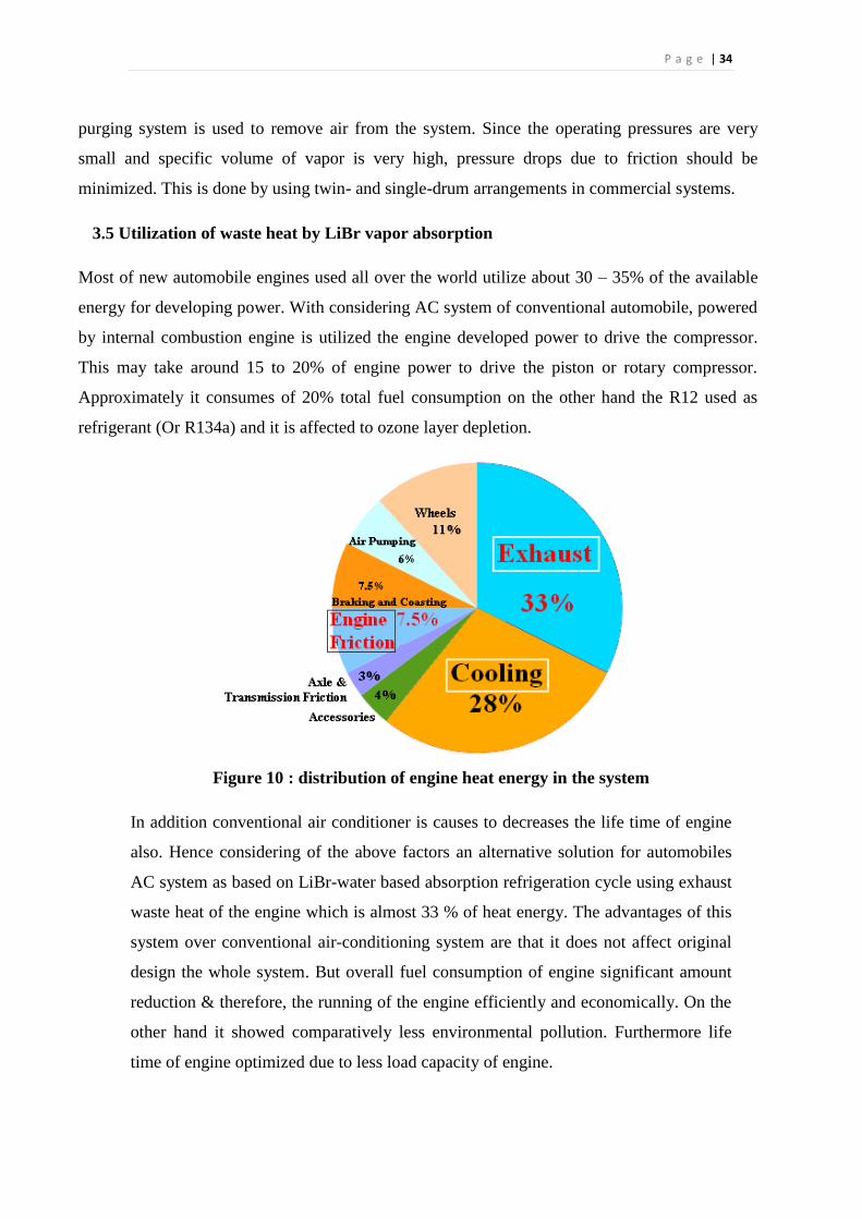
3.5 Utilization of waste heat by LiBr vapor absorption
Most of new automobile engines used all over the world utilize about 30 – 35% of the available
energy for developing power. With considering AC system of conventional automobile, powered
by internal combustion engine is utilized the engine developed power to drive the compressor.
This may take around 15 to 20% of engine power to drive the piston or rotary compressor.
Approximately it consumes of 20% total fuel consumption on the other hand the R12 used as
refrigerant (Or R134a) and it is affected to ozone layer depletion.
Figure 10 : distribution of engine heat energy in the system
In addition conventional air conditioner is causes to decreases the life time of engine
also. Hence considering of the above factors an alternative solution for automobiles
AC system as based on LiBr-water based absorption refrigeration cycle using exhaust
waste heat of the engine which is almost 33 % of heat energy. The advantages of this
system over conventional air-conditioning system are that it does not affect original
design the whole system. But overall fuel consumption of engine significant amount
reduction & therefore, the running of the engine efficiently and economically. On the
other hand it showed comparatively less environmental pollution. Furthermore life
time of engine optimized due to less load capacity of engine.
P a g e | 35
Here exhaust waste heat is used as power source and it may not consume engine
developed power for cooling the vehicle’s cabin. On the other hand in this design water is
used as a refrigerant. It reduces the environmental impact. Existing components other
than the compressor can be used as usual with this modification. However an economical
heat exchanger/generator has introduced to proper functioning of the system.
3.6 Advantages of VARS
As there is no moving part in the entire system, the operation is essentially quite and
subjected to a very little wear.
The load variation does not effect the performance of a vapor absorption system.
Absorption system may be designed to use any readily available source of thermal energy
such as process steam, hot exhaust from furnaces and solar energy; therefore they can be
used in places where electric power is hard to obtain or is very expensive.
In here pump is used for pumping refrigerant absorbent solution, which consumes less
power.
Maintenance cost is low as because of absence of moving part.
In the absorption refrigeration system no refrigerant produces the greenhouse effect, so
their use won’t be stopped in future.
No moving part except pump-motor, which is comparatively smaller than compressor
system.
Quiet in operation, low maintenance cost.
Can work only with thermal energy as an input.
Can be built for huge working capacities. (even for above 1000 TR)
Can be operated at designed C.O.P’s or even at part loads by varying generator
temperature.
Space and automatic control requirements favor absorption system.
In ammonia-water absorption refrigeration system, ammonia is used as the refrigerant,
which is easily and cheaply available.
In lithium bromide system, water is used as the refrigerant, which is also available cheap.
P a g e | 36
3.7 Advantages of Lithium bromide -Water over Ammonia-Water
It uses water as refrigerant(boiling point 100ºC) and Lithium-Bromide (boiling point
1265ºC) as its absorbent
Is used in a number of air conditioning applications.
This system is useful for applications where the temperature required is more than 32 ºF
(0ºC).
Water used as the refrigerant in the absorption refrigeration system means the operating
pressures in the condenser and the evaporator must be very low.
The system can be achieved even without installing the expansion valve in the system,
since the drop in pressure occurs due to friction in the refrigeration piping and in the
spray nozzles.
It has lesser components than ammonia-water absorption.
3.8 Disadvantages of VARS
1) Initial capital cost:
Though the running cost of the absorption refrigeration system is much lesser than the vapor
compression system. Its initial capital cost is much higher.
2) Corrosive nature of lithium bromide:
In the lithium bromide absorption refrigeration system, lithium bromide is corrosive in nature,
which reduces the overall life of the system. In case of the ammonia system, ammonia is
corrosive to copper. In the vapor compression system copper is used with the halocarbon
refrigerants and they are quite safe thus ensuring long life of the refrigeration system. As such the
vapor compression system with reciprocating or centrifugal compressor has longer life than the
lithium bromide absorption refrigeration system.

P a g e | 37
3) Low working pressure:
The working pressures of the absorption refrigeration cycle are very low. In case of the lithium
bromide system these pressures are so low that even the expansion valve is not required since the
drop in pressure of the refrigerant due to its flow is good enough to produce its expansion. Due to
this the refrigeration system should be sealed thoroughly so that no atmospheric gases would
enter the refrigeration system. As such the system of the compression refrigeration should also be
packed tightly, but this is to prevent the leakage of the refrigerant to the atmosphere.
4) Coefficient of Performance (COP):
The coefficient of performance of the absorption refrigeration systems is very low compared to
the vapor compression systems. For instance, the COP of the two stage lithium bromide system is
about 1.1, while that of the vapor compression system used for the air conditioning applications it
is about 4 to 5.Thus the absorption refrigeration system becomes competitive only if the ratio of
the electricity to fuel (oil, gas or coal used to generate the steam in the boiler) becomes more than
four. If this ratio is lesser there are chances that excess fuel would be required the steam.
However, if there is excess steam in the industry, this ratio may not be given importance.
5) Higher heat rejection:
In the absorption refrigeration heat has to be rejected from number of parts like condenser,
absorber, analyzer, rectifier etc. thus heat rejection factor for absorption refrigeration system is
high and it can be around 2.5. In the compression refrigeration system the heat is given up only
from the condenser, so it heat rejection factor is small, which is about 1.2. Thus the cooling tower
and pump capacities for pumping the cooling water have to be higher in case of the absorption
refrigeration system, which leads to increase in the running cost of the system
P a g e | 38
Chapter Four
Design consideration
4.1. Introduction
4.2. Factor affecting the system.
1. Design of Solution Heat Exchange
2. Design of energy supplying system to the generator
3. Design of an air Cooled Condenser
4. Design of Generator and Absorber
5. Evaporator Design
6. Evaporator Design Factors
7. Capillary Tube
8. Safety Measurements with Lithium Bromide
9. Condenser size
P a g e | 39
4.1 Introduction
Various economic and ecological reasons make it necessary to look more in detail at the potential
performance improvements of refrigeration systems. More energy efficient systems have to be
developed because of stricter energy standards issued all over the world. American refrigerator
manufacturers are being forced by the government and by environmental and economic interests
to produce more energy efficient systems and to eliminate chlorofluorocarbons (CFCs). Though
in VARS there is no CFC in use, still we need to maintain various design standards to make the
system work properly. Designing of the system can vary the performance of the system. So all
the goal mentioned can only be achieved if a system is properly designed and built.
4.2 Factor affecting the system
4.2.1 Design of Solution Heat Exchanger
The efficiency of the system is greatly affected by the enthalpy of solution entering the
generator and temperature of the solution entering the absorber. Thus a proper heat exchanger is
necessary for enhancement of this refrigeration system.
4.2.2 Design of energy supplying network to the generator
The prime motive behind this project was to utilize exhaust heat energy which is released from
internal combustion engines. This can be used by many industries and manufacturing unit’s
exhaust that go unused as well. This energy should be trapped and supplied to the generator. A
proper system should be designed for this purpose.
4.2.3 Design of an water Cooled Condenser
A properly designed water cooled condenser will reduce the size of the refrigeration system
and make it compact, easy to transport and efficient.
4.2.4 Design of Generator and Absorber
Since the system is operating under high pressure, the cylinders for generator and absorber must
be selected properly so that they can withstand the pressure making the system cost effective.
P a g e | 40
4.2.5 Evaporator Design
The contamination hazards make the evaporator the most challenging part of a
refrigeration system to Design.
Selection of the correct materials of construction:
Evaporators can be constructed either in hot dipped galvanized steel, aluminum or stainless steel.
Although combination of stainless steel pipes or copper tubes with aluminum fins are also
possible. It is important to choose a material that can withstand both the refrigerant vapor and the
chemicals needed. The large number of welds, the numerous transitions from one metal to
another, the small pipe coil etc. make the Evaporator very sensitive for the aggressive cleaning
chemicals.
Carbon steel on a per kg basis, is lower in cost than both stainless steel and aluminum,
however carbon steel becomes brittle in temperatures below -29°C. Special allowances
must be made when designing with carbon steel below -29˚C.
Galvanized steel, carbon steel are dipped in a bath of molten zinc is also used as
material of construction for LiBr evaporator coils.
4.2.6 Evaporator Design Factors
There are 3 main factors to consider in designing an evaporator.
Pressure Drop: The evaporator must have sufficient space for the circulation of the
refrigerant without too much pressure drop between the outlet and the inlet.
Temperature: The evaporator must have enough surface area to absorb the required heat
load in order to ensure the temperature difference between the substances being cooled.
Liquid and Refrigerant Vapor: The evaporator must have enough space for the liquid
refrigerant and the vapor to separate from the liquid.
P a g e | 41
4.2.7 Capillary Tube
Since the pressure on the two sides of the capillary equalizes when the refrigeration plant is
stopped, one should not overcharge the system with the refrigerant. Due to this reason the
receiver is also not installed in the refrigeration system with the capillary. If the system is
overcharged the discharge pressure from the compressor will be high and the compressor would
get overloaded. Thus the refrigerant charge in the refrigeration and air conditioning systems with
the capillary tube is critical.
The technician should be very careful while brazing the capillary to the condenser and
the evaporator coil. Since the diameter of the capillary is very small the capillary may get
blocked if the brazing is done deep inside. Brazing the capillary requires lots of expertise and
patience.
In most of the cases, when the fresh refrigerant is charged into the refrigerator or the deep
freezers, the capillary of the system should also be changed. This is because when the machine is
stopped some particles may clog the capillary as the refrigerant leaks to the atmosphere.
4.2.8 Safety Measurements with Lithium Bromide
Lithium Bromide is a hazardous chemical that can cause fatal injury if not handled properly.
Lithium salts are psychoactive and somewhat corrosive. Heat is quickly generated when lithium
bromide is dissolved into water because it has a negative enthalpy of solution.
Potential health effects
Inhalation: May be harmful if inhaled. Causes respiratory tract irritation.
in: May be harmful if absorbed through skin. Causes allergic skin reaction and irritation.
Eyes: Causes serious eye irritation.
Ingestion: Harmful if swallowed.
Precautionary Statements
Avoid breathing fumes, gas, mist, vapors, and spray.
P a g e | 42
Wash hands thoroughly after handling.
Use only outdoors or in a well ventilated area.
Avoid release to the environment
Wear protective gloves / protective clothing / eye protection / face protection
IF SWALLOWED: Rinse mouth. Do NOT induce vomiting.
IF ON SKIN (or hair): Wash with plenty of soap and water
IF INHALED: Remove victim to fresh air and keep at rest in a position comfortable for
breathing.
IF IN EYES: Rinse cautiously with water for several minutes. Remove contact lenses,
if present and easy to do so.
Continue rinsing. .
Wash contaminated clothing before reuse.
Eliminate all ignition sources if safe to do so.
Collect Spillage.
Store in a well ventilated place. Keep container tightly closed.
Store locked up.
Dispose of contents/container in accordance with specified local, regional,
national, international regulations for disposal.
Product disposal
The generation of waste should be avoided or minimized wherever possible. Avoid dispersal of
spilled material, runoff and contact with soil, waterways, drains and sewers. Disposal of this
product, solutions and any byproducts should at all times comply with the requirements of
environmental protection and waste disposal legislation and any regional and local authority
requirements. Contact a licensed professional waste disposal service to dispose of this material.
Regulatory Information
This product has been classified in accordance with the hazard criteria of the Controlled Products
Regulations and the MSDS contain all the information required by the Controlled Products
Regulation.
P a g e | 43
4.2.9 Condenser size:
The selection of a higher condensing head pressure is one of the best ways to reduce energy costs
to save energy in a LiBr refrigeration system. The larger condenser saves money all year round,
and offers the user a longer useful lifetime as well.
Sizing Condensers: There are three factors inexhaustncing the sizing of a condenser:
a) The total heat rejection required - the capacity of the system heat source.
b) The local climate conditions - the design wet bulb temperature
c) The design condensing temperature.
The first two factors are a given and cannot be changed. The third is a design decision between
the owner and designer.
Total Heat Rejection: Total heat rejection is based on the total compressor capacity of the Plant
including a factor for oil cooling and excluding any back up machines. The equation is:
(𝐵𝐻𝑃 × 2545) + (𝑇𝑅 × 12000) = 𝑇𝑜𝑡𝑎𝑙 𝐻𝑒𝑎𝑡 𝑅𝑒𝑗𝑒𝑐𝑡𝑖𝑜𝑛, 𝐵𝑇𝑈/ℎ𝑟.
Wet Bulb Temperature: Evaporative condensers work by evaporating water over the
condenser‘s tube bundle cooling the refrigerant vapor inside. The temperature at which the water
will evaporate on any given day is called the wet bulb temperature. The wet bulb temperature is a
measure of the humidity in the air. If the humidity is high, the wet bulb temperature is high. The
dry bulb temperature, which is the temperature measured by a thermometer, has significantly less
effect on condenser performance. Refrigeration system designer’s size condensers using the
ASHRAE 1% wet bulb temperature for a given location. In other words, 99% of the time the wet
bulb temperature will be below that value. Typical wet bulb value for the Bangladesh is about
27°C.
Design Condensing Temperature: This is a key economic design decision. Lowering the design
condensing temperature lowers the energy consumption by the compressors. However, lowering
the design condensing temperature also increases the size and cost of the condenser, raising
installation costs. Thus, the decision is balance between initial construction cost and operating
costs.
P a g e | 44
Lowering Condensing Pressure:
There are 3 design condensing temperatures typically used for LiBr refrigeration systems.
a) 96.3°F 185 psig (older standard design)
b) 95°F 180.7 psig (newer standard design)
c) 90°F 165.9 psig (enhanced design )
Using the older standard of 96.3°F as a base, lowering the design condensing temperature has the
following effect on size, or base rating, of the condenser.
Other Considerations:
Scaling of the condenser tubes from hard water is a major factor meeting a condensers useful life.
Even the best warm water treatment will not prevent scale from eventually building up, but it will
slow it down so that it will take many years before it becomes a problem, condenser manufacturers
report that even a very thin layer of scale on tubes has a significant effect on condenser performance.
For example, with a fouling factor of 0.003 (0.036 in scale thickness) the additional energy cost per
year for a 500 ton chiller is $25,300. The larger sized condenser has a built in safety factor of
approximately 50%, allowing it to operate satisfactorily for years even with some tube scaling,
whereas the marginally sized condenser will lead to high head pressure problems much sooner.
Thus, the larger condenser will have a significantly longer useful life.
P a g e | 45
Chapter Five
Design and implementation
5.1 Equipment required for implementing the design.
5.2 Fabrication and assembly.
P a g e | 46
5.1 Equipment required for implementing the design.
Major Components:
5.1.1 Generator:
The purpose of the generator is to deliver the refrigerant vapor to the rest of the system. It
accomplishes this by separating refrigerant from the solution. In the generator the solution
vertically falls over horizontal tubes with high temperature energy source typically steam or hot
water flowing through the tubes. The solution absorbs heat from the warm steam or water,
causing the refrigerant to boil (vaporize) and separate from the absorbent solution. As the
refrigerant is boiled away, the absorbent solution becomes more concentrated. The concentrated
absorbent solution returns to the absorber and the refrigerant vapor migrates to the condenser.
It can be seen that compared to heat input to the system at the generator, the work input to the
system is almost negligible (less than 0.5 percent). The system COP is reduced as the required
heat input to the generator increases due to heat rejection at dephlegmator. However, this cannot
be avoided as rectification of the vapor is required. However, it is possible to analyze the
rectification process to minimize the heat rejection at the dephlegmator.
Figure 11 : Major components of VARS
P a g e | 47
Solar energy as heat source of generator
Solar energy is a very large, inexhaustible source of energy. The power from the sun intercepted
by the earth is approximately 𝟏. 𝟖 × 𝟏𝟎𝟏𝟏 MW which is much larger than the present
consumption rate on the earth of all commercial energy sources. Thus, in principle, solar energy
could supply all the present and future energy needs of the world on the continuing basis. This
makes it one of the most promising of the unconventional energy sources. In addition to its size,
solar energy has two other factors in its favor. First unlike fossil fuels and nuclear power, it is an
environmental clean source of energy. Second, it is free and available in adequate quantities in
almost all parts of the world where people live. However, there are many problems associated
with its use. The main problem is that it is a dilute source of energy. Even in the hottest regions
on earth, the solar radiation flux rarely exceeds l kWh/m2 and the total radiation over a day is at
best about 6kWh/m2. These are low values from the point of view of technological utilization.
Consequently, large collecting areas are required in many applications and this result in excessive
costs.
Internal combustion engines as heat source of generator
Efficiency of diesel engine is about 35-40% remaining energy go waste. Maximum energy wastes
in exhaust. In diesel engine 30-32% energy go waste in exhaust. So it is important to recover
energy from exhaust. Approximately l5% of all the electricity produced in the Whole World is
employed for refrigeration and air conditioning system. During recent years research aimed at the
development of technologies that can offer reductions in energy consumption, peak electrical
demand and energy costs without lowering the desired level of comfort conditions has intensified.
By reason that absorption refrigeration technologies have the advantage that the peaks of
requirements with the availability of the waste heat.
It is well known that energy shortage and environmental pollution have become global issues of
common concern. As the most widely used source of primary power for machinery critical to the
transportation, construction and agricultural sectors, engine has consumed more than 60% of
fossil oil. On the other hand, the amount of C02 gas released from engine, just for transportation
applications, makes up 25% of all human activity related C02 emissions. Thus, energy
P a g e | 48
conservation on engine is one of best ways to deal with these problems since it can improve the
energy utilization efficiency of engine and reduces emissions.
Function of Generator in absorption system
In generator of absorption chillers weak solution is heated by operating steam (steam absorption
chillers), hot water or exhaust gases in indirect tired absorption chillers. While direct fired
absorption chillers are Natural gas, Diesel or Kerosene Oil Operated. Alter heating in generator
solution is concentrated and high temperature refrigerant vapors are produced. Alter generator
process in a chiller high temperature and pressure refrigerant vapors travel to condenser. A strong
solution enters absorber through heat exchanger in exchanging heat with weak solution.
5.1.2 Condenser
In systems involving heat transfer, a condenser is a device or unit used to condense a substance
from its gaseous to its liquid state, by cooling it. In so doing, the latent heat is given up by the
substance, and will transfer to the condenser coolant. Condensers are typically heat exchangers
which have various designs and come in many sizes ranging from rather small (hand held) to
very large scale.
Alter the refrigerant gas is released from the generator, it flows into the Condenser (Condensers
and Evaporators are also known as "coils"). As the electric condenser fan causes ambient air to
flow through the cooling tins of the Condenser, this flowing air absorbs heat contained in the
refrigerant that is flowing through the internal Condenser surfaces. Note again that this
condensation process takes place at the condensation temperature ("boiling point") consistent
with the pressure 'n the Condenser. The actual condenser pressure (and therefore, temperature) is
determined by a number of factors including the rate of air flow across the condenser, its design
and physical size, the ambient air temperature and the refrigerant flow rate (compressor size and
speed).
When enough heat has been absorbed by the outside air (or, conversely, rejected by the
refrigerant), all of the refrigerant gas will become condensed from gas to liquid form at constant
P a g e | 49
temperature. Any further heat rejected to the outside air results in the liquid refrigerant becoming
cooler than the boiling point and is known as liquid “sub cooling.”
Generally, the more sub cooling, the better because more heat is transferred to the surroundings,
and, therefore, more heat can be transferred tram the region being air conditioned. (However, sub
cooling is expensive 'n terms of condenser size and cost because additional heat transfer area is
required to transfer additional heat at a continuously decreasing temperature difference.)
Function of condenser
The purpose of condenser is to condense the refrigerant vapors. Inside the condenser, cooling
water flows through tubes and the hot refrigerant vapor fills the surrounding space. As heat
transfers from the refrigerant vapor to the water, refrigerant condenses on the tube surfaces. The
condensed liquid refrigerant collects in the bottom of the condenser before travelling to the
expansion device. The cooling water system is connected to a cooling tower.
5.1.3 Absorber
The absorber is a major component of absorption cycle systems, and its performance directly
impacts the overall size and energy supplies of these devices. Absorption cooling and heating
cycles have different absorber design requirements: in absorption cooling systems, the absorber
works close to ambient temperature, therefore, the mass transfer is the most important
phenomenon in order to reduce the generator size; on the other hand, in heat transformer
absorption systems, is important to recover the heat delivered by exothermic reactions produced
in the absorber.
The working fluid flows into the evaporator, where it evaporates at a reduced pressure and
temperature, taking heat from environment (QEV). The working fluid vapor from the evaporator
is absorbed at low pressure into the concentrated absorber solution in the component called
absorber. A quantity of heat (QAB) is released as much as the refrigerant vapor is absorbed. This
heat is removed by some cooling fluid (air, water or another fluid) from the absorber. The diluted
absorber solution in the absorber is pumped to energy recovery device called “economizer”. In
P a g e | 50
this component, the concentrated absorber solution preheats the diluted absorber solution before
reaching the generator. In the generator, a part of the working fluid is vaporized from the diluted
absorber solution by addition of a quantity of heat (QGE) at high temperature and pressure. The
working fluid vapor is condensed at high pressure and temperature in the condenser with removal
of heat (QCO) to the ambient. The working fluid liquid in the condenser is returned to the
evaporator through the expansion valve. Then the absorption cycle repeats from the evaporator.
Figure shows a schematic diagram of the described cycle. In these devices, the absorber is near to
ambient temperature, and the cooling effect occurs in the evaporator, however, the absorber
performance directly affects the energy supply to the generator, therefore, a correct absorber
design is desirable. In a cooling cycle absorber design, it is well known that the absorption of the
refrigerant vapor into the working solution is possible only when the latter is sub cooled and that
the solution, upon leaving the absorber, is still sub-cooled.
5.1.4 Evaporator
The purpose of the evaporator is to remove unwanted heat from the product, via the liquid
refrigerant. The liquid refrigerant contained within the evaporator is boiling at a low pressure.
The level of this pressure is determined by two factors: The rate at which the heat is absorbed
from the product to the liquid refrigerant in the evaporator The rate at which the low pressure
vapor is removed from the evaporator by the compressor to enable the transfer of heat, the
temperature of the liquid refrigerant must be lower than the temperature of the product being
cooled Once transferred, the liquid refrigerant is drawn from the evaporator by the compressor
via the suction line. When leaving the evaporator coil the liquid refrigerant is in vapor form.
5.1.5 Expansion valve:
Expansion valves are flow-restricting devices that cause a pressure drop of the working fluid.
The valve needle remains open during steady state operation. The size of the opening or the
position of the needle is related to the pressure and temperature of the evaporator. There are three
main parts of the expansion valve that regulate the position of the needle. A sensor bulb, at the
end of the evaporator, monitors the temperature change of the evaporator. This change in
temperature creates a change in pressure on the diaphragm.
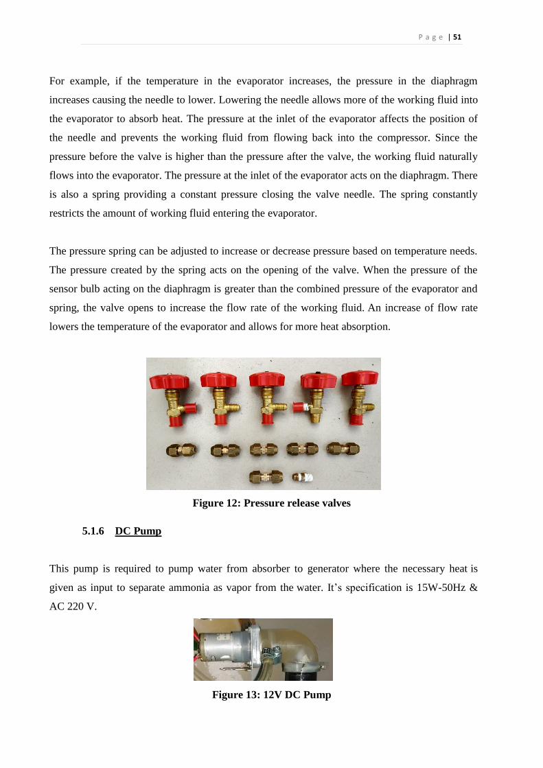
P a g e | 51
For example, if the temperature in the evaporator increases, the pressure in the diaphragm
increases causing the needle to lower. Lowering the needle allows more of the working fluid into
the evaporator to absorb heat. The pressure at the inlet of the evaporator affects the position of
the needle and prevents the working fluid from flowing back into the compressor. Since the
pressure before the valve is higher than the pressure after the valve, the working fluid naturally
flows into the evaporator. The pressure at the inlet of the evaporator acts on the diaphragm. There
is also a spring providing a constant pressure closing the valve needle. The spring constantly
restricts the amount of working fluid entering the evaporator.
The pressure spring can be adjusted to increase or decrease pressure based on temperature needs.
The pressure created by the spring acts on the opening of the valve. When the pressure of the
sensor bulb acting on the diaphragm is greater than the combined pressure of the evaporator and
spring, the valve opens to increase the flow rate of the working fluid. An increase of flow rate
lowers the temperature of the evaporator and allows for more heat absorption.
Figure 12: Pressure release valves
5.1.6 DC Pump
This pump is required to pump water from absorber to generator where the necessary heat is
given as input to separate ammonia as vapor from the water. It’s specification is 15W-50Hz &
AC 220 V.
Figure 13: 12V DC Pump
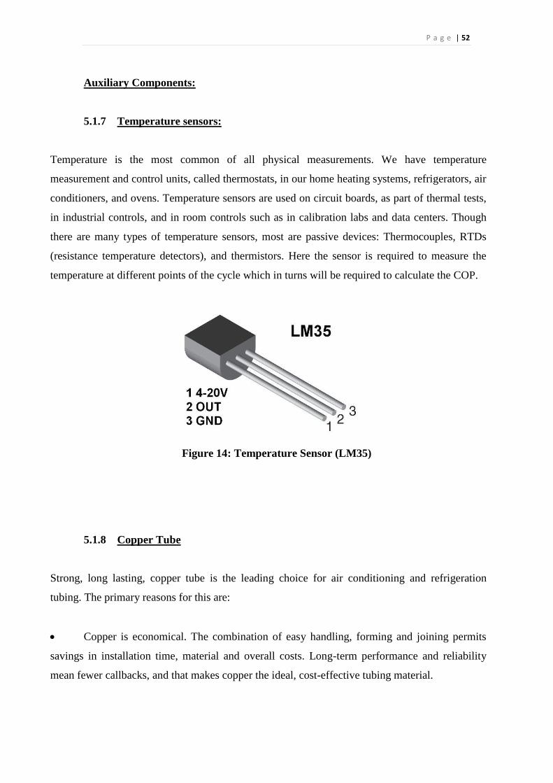
P a g e | 52
Auxiliary Components:
5.1.7 Temperature sensors:
Temperature is the most common of all physical measurements. We have temperature
measurement and control units, called thermostats, in our home heating systems, refrigerators, air
conditioners, and ovens. Temperature sensors are used on circuit boards, as part of thermal tests,
in industrial controls, and in room controls such as in calibration labs and data centers. Though
there are many types of temperature sensors, most are passive devices: Thermocouples, RTDs
(resistance temperature detectors), and thermistors. Here the sensor is required to measure the
temperature at different points of the cycle which in turns will be required to calculate the COP.
Figure 14: Temperature Sensor (LM35)
5.1.8 Copper Tube
Strong, long lasting, copper tube is the leading choice for air conditioning and refrigeration
tubing. The primary reasons for this are:
Copper is economical. The combination of easy handling, forming and joining permits
savings in installation time, material and overall costs. Long-term performance and reliability
mean fewer callbacks, and that makes copper the ideal, cost-effective tubing material.
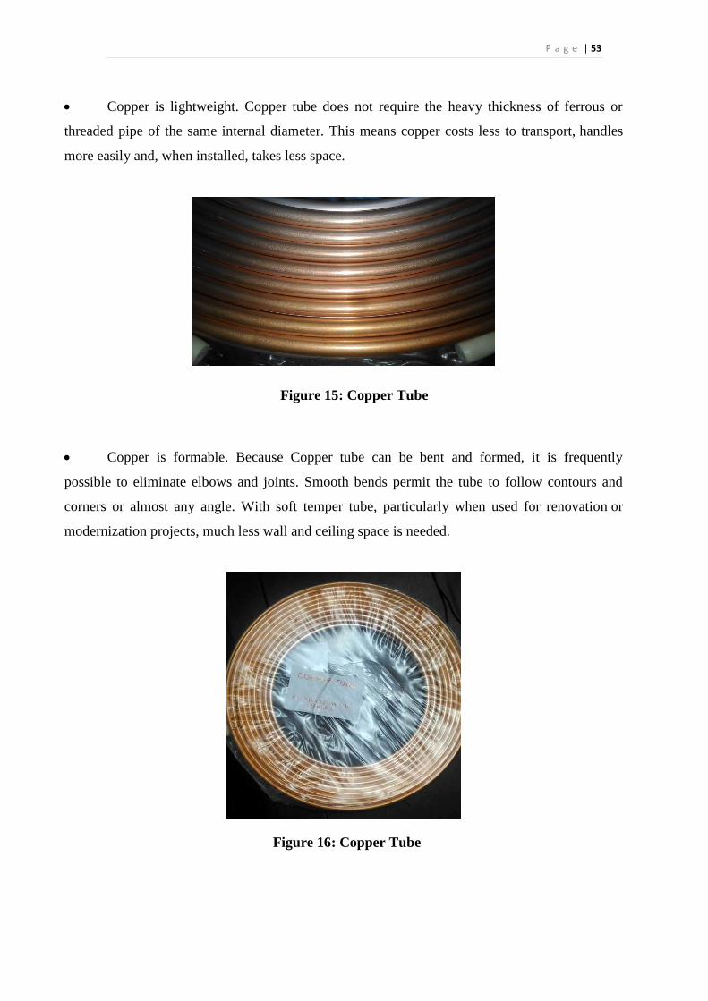
P a g e | 53
Copper is lightweight. Copper tube does not require the heavy thickness of ferrous or
threaded pipe of the same internal diameter. This means copper costs less to transport, handles
more easily and, when installed, takes less space.
Figure 15: Copper Tube
Copper is formable. Because Copper tube can be bent and formed, it is frequently
possible to eliminate elbows and joints. Smooth bends permit the tube to follow contours and
corners or almost any angle. With soft temper tube, particularly when used for renovation or
modernization projects, much less wall and ceiling space is needed.
Figure 16: Copper Tube
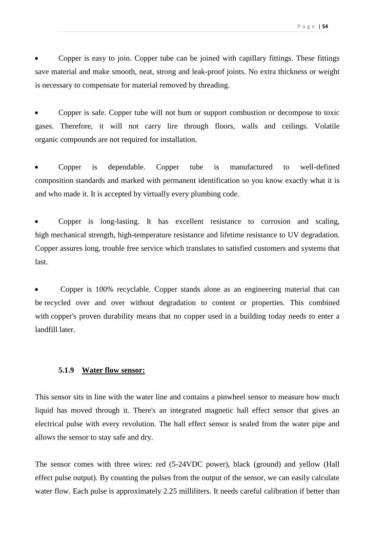
P a g e | 54
Copper is easy to join. Copper tube can be joined with capillary fittings. These fittings
save material and make smooth, neat, strong and leak-proof joints. No extra thickness or weight
is necessary to compensate for material removed by threading.
Copper is safe. Copper tube will not bum or support combustion or decompose to toxic
gases. Therefore, it will not carry lire through floors, walls and ceilings. Volatile
organic compounds are not required for installation.
Copper is dependable. Copper tube is manufactured to well-defined
composition standards and marked with permanent identification so you know exactly what it is
and who made it. It is accepted by virtually every plumbing code.
Copper is long-lasting. It has excellent resistance to corrosion and scaling,
high mechanical strength, high-temperature resistance and lifetime resistance to UV degradation.
Copper assures long, trouble free service which translates to satisfied customers and systems that
last.
Copper is 100% recyclable. Copper stands alone as an engineering material that can
be recycled over and over without degradation to content or properties. This combined
with copper's proven durability means that no copper used in a building today needs to enter a
landfill later.
5.1.9 Water flow sensor:
This sensor sits in line with the water line and contains a pinwheel sensor to measure how much
liquid has moved through it. There's an integrated magnetic hall effect sensor that gives an
electrical pulse with every revolution. The hall effect sensor is sealed from the water pipe and
allows the sensor to stay safe and dry.
The sensor comes with three wires: red (5-24VDC power), black (ground) and yellow (Hall
effect pulse output). By counting the pulses from the output of the sensor, we can easily calculate
water flow. Each pulse is approximately 2.25 milliliters. It needs careful calibration if better than
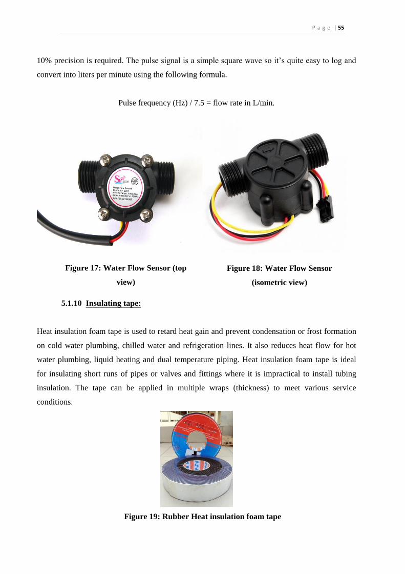
P a g e | 55
10% precision is required. The pulse signal is a simple square wave so it’s quite easy to log and
convert into liters per minute using the following formula.
Pulse frequency (Hz) / 7.5 = flow rate in L/min.
Figure 17: Water Flow Sensor (top
view)
Figure 18: Water Flow Sensor
(isometric view)
5.1.10 Insulating tape:
Heat insulation foam tape is used to retard heat gain and prevent condensation or frost formation
on cold water plumbing, chilled water and refrigeration lines. It also reduces heat flow for hot
water plumbing, liquid heating and dual temperature piping. Heat insulation foam tape is ideal
for insulating short runs of pipes or valves and fittings where it is impractical to install tubing
insulation. The tape can be applied in multiple wraps (thickness) to meet various service
conditions.
Figure 19: Rubber Heat insulation foam tape
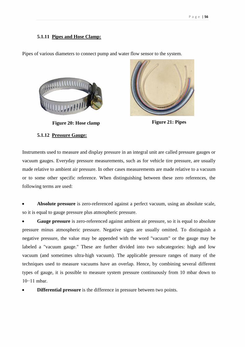
P a g e | 56
5.1.11 Pipes and Hose Clamp:
Pipes of various diameters to connect pump and water flow sensor to the system.
Figure 20: Hose clamp
Figure 21: Pipes
5.1.12 Pressure Gauge:
Instruments used to measure and display pressure in an integral unit are called pressure gauges or
vacuum gauges. Everyday pressure measurements, such as for vehicle tire pressure, are usually
made relative to ambient air pressure. In other cases measurements are made relative to a vacuum
or to some other specific reference. When distinguishing between these zero references, the
following terms are used:
Absolute pressure is zero-referenced against a perfect vacuum, using an absolute scale,
so it is equal to gauge pressure plus atmospheric pressure.
Gauge pressure is zero-referenced against ambient air pressure, so it is equal to absolute
pressure minus atmospheric pressure. Negative signs are usually omitted. To distinguish a
negative pressure, the value may be appended with the word "vacuum" or the gauge may be
labeled a "vacuum gauge." These are further divided into two subcategories: high and low
vacuum (and sometimes ultra-high vacuum). The applicable pressure ranges of many of the
techniques used to measure vacuums have an overlap. Hence, by combining several different
types of gauge, it is possible to measure system pressure continuously from 10 mbar down to
10−11 mbar.
Differential pressure is the difference in pressure between two points.
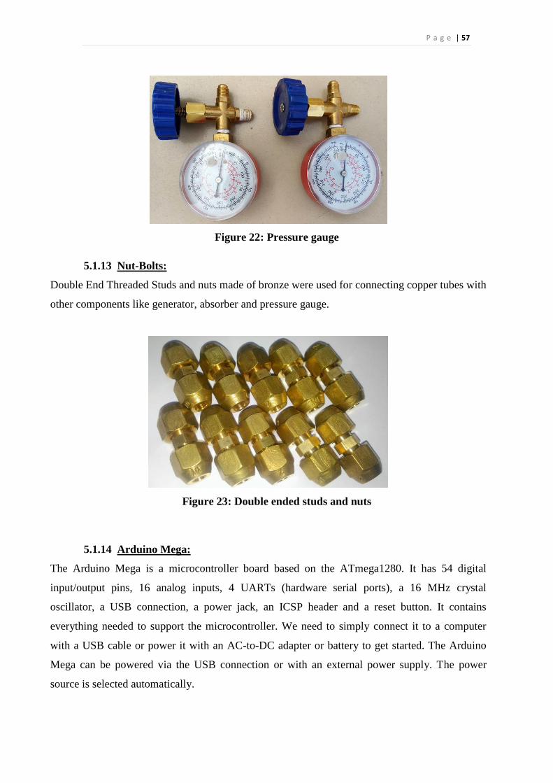
P a g e | 57
Figure 22: Pressure gauge
5.1.13 Nut-Bolts:
Double End Threaded Studs and nuts made of bronze were used for connecting copper tubes with
other components like generator, absorber and pressure gauge.
Figure 23: Double ended studs and nuts
5.1.14 Arduino Mega:
The Arduino Mega is a microcontroller board based on the ATmega1280. It has 54 digital
input/output pins, 16 analog inputs, 4 UARTs (hardware serial ports), a 16 MHz crystal
oscillator, a USB connection, a power jack, an ICSP header and a reset button. It contains
everything needed to support the microcontroller. We need to simply connect it to a computer
with a USB cable or power it with an AC-to-DC adapter or battery to get started. The Arduino
Mega can be powered via the USB connection or with an external power supply. The power
source is selected automatically.
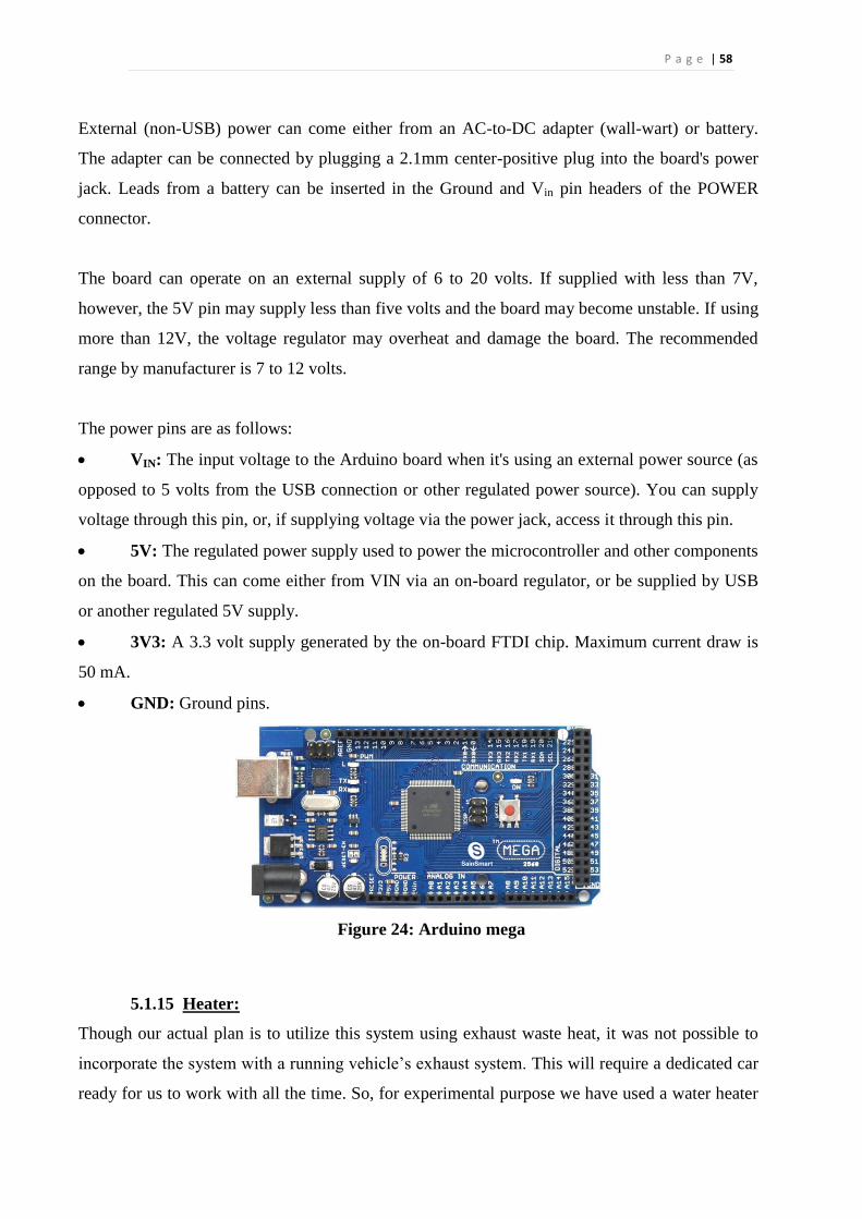
P a g e | 58
External (non-USB) power can come either from an AC-to-DC adapter (wall-wart) or battery.
The adapter can be connected by plugging a 2.1mm center-positive plug into the board's power
jack. Leads from a battery can be inserted in the Ground and Vin pin headers of the POWER
connector.
The board can operate on an external supply of 6 to 20 volts. If supplied with less than 7V,
however, the 5V pin may supply less than five volts and the board may become unstable. If using
more than 12V, the voltage regulator may overheat and damage the board. The recommended
range by manufacturer is 7 to 12 volts.
The power pins are as follows:
VIN: The input voltage to the Arduino board when it's using an external power source (as
opposed to 5 volts from the USB connection or other regulated power source). You can supply
voltage through this pin, or, if supplying voltage via the power jack, access it through this pin.
5V: The regulated power supply used to power the microcontroller and other components
on the board. This can come either from VIN via an on-board regulator, or be supplied by USB
or another regulated 5V supply.
3V3: A 3.3 volt supply generated by the on-board FTDI chip. Maximum current draw is
50 mA.
GND: Ground pins.
Figure 24: Arduino mega
5.1.15 Heater:
Though our actual plan is to utilize this system using exhaust waste heat, it was not possible to
incorporate the system with a running vehicle’s exhaust system. This will require a dedicated car
ready for us to work with all the time. So, for experimental purpose we have used a water heater
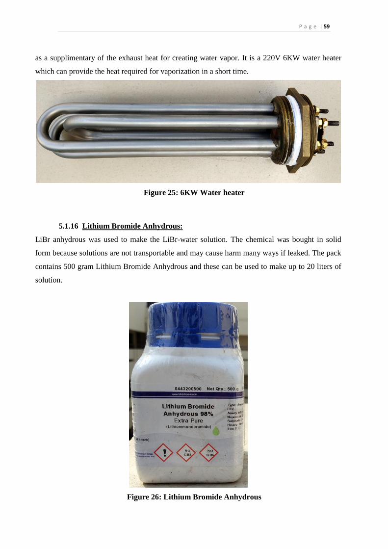
P a g e | 59
as a supplimentary of the exhaust heat for creating water vapor. It is a 220V 6KW water heater
which can provide the heat required for vaporization in a short time.
Figure 25: 6KW Water heater
5.1.16 Lithium Bromide Anhydrous:
LiBr anhydrous was used to make the LiBr-water solution. The chemical was bought in solid
form because solutions are not transportable and may cause harm many ways if leaked. The pack
contains 500 gram Lithium Bromide Anhydrous and these can be used to make up to 20 liters of
solution.
Figure 26: Lithium Bromide Anhydrous
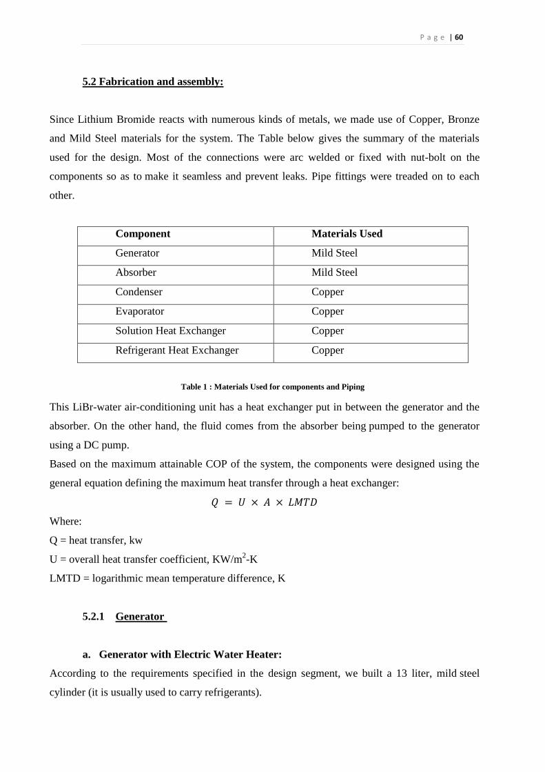
P a g e | 60
5.2 Fabrication and assembly:
Since Lithium Bromide reacts with numerous kinds of metals, we made use of Copper, Bronze
and Mild Steel materials for the system. The Table below gives the summary of the materials
used for the design. Most of the connections were arc welded or fixed with nut-bolt on the
components so as to make it seamless and prevent leaks. Pipe fittings were treaded on to each
other.
Component Materials Used
Generator Mild Steel
Absorber Mild Steel
Condenser Copper
Evaporator Copper
Solution Heat Exchanger Copper
Refrigerant Heat Exchanger Copper
Table 1 : Materials Used for components and Piping
This LiBr-water air-conditioning unit has a heat exchanger put in between the generator and the
absorber. On the other hand, the fluid comes from the absorber being pumped to the generator
using a DC pump.
Based on the maximum attainable COP of the system, the components were designed using the
general equation defining the maximum heat transfer through a heat exchanger:
𝑄 = 𝑈 × 𝐴 × 𝐿𝑀𝑇𝐷
Where:
Q = heat transfer, kw
U = overall heat transfer coefficient, KW/m2-K
LMTD = logarithmic mean temperature difference, K
5.2.1 Generator
a. Generator with Electric Water Heater:
According to the requirements specified in the design segment, we built a 13 liter, mild steel
cylinder (it is usually used to carry refrigerants).
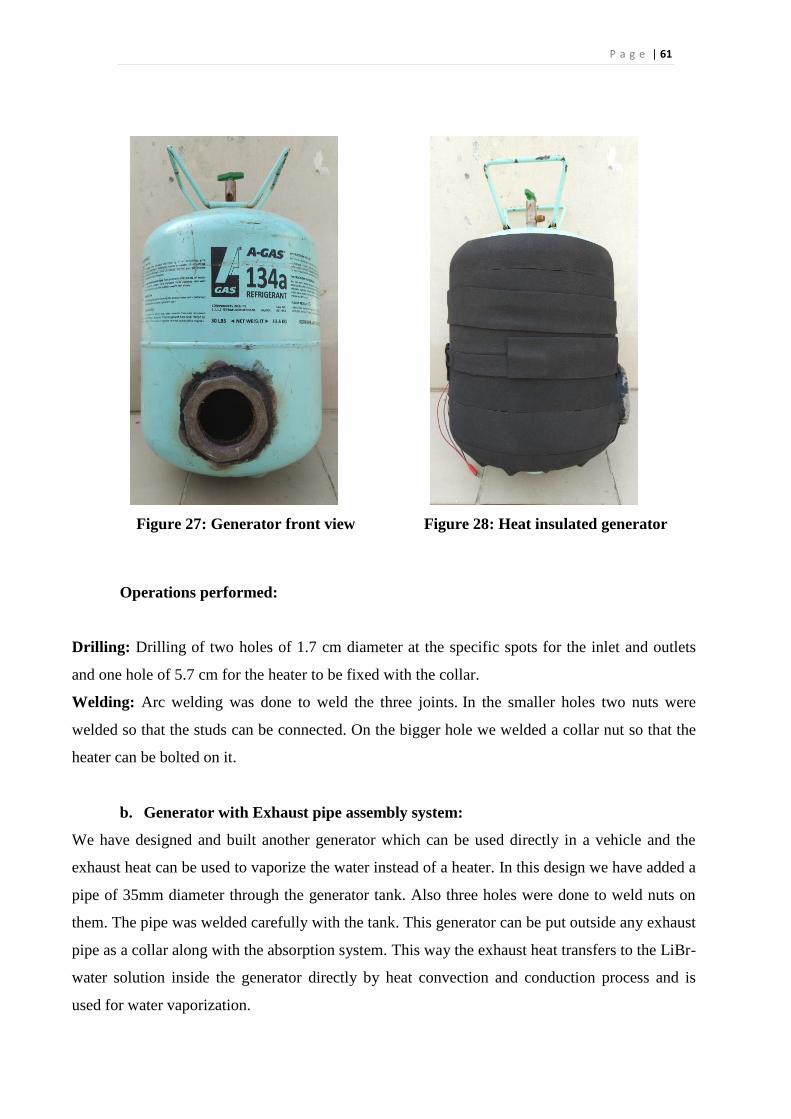
P a g e | 61
Figure 27: Generator front view
Figure 28: Heat insulated generator
Operations performed:
Drilling: Drilling of two holes of 1.7 cm diameter at the specific spots for the inlet and outlets
and one hole of 5.7 cm for the heater to be fixed with the collar.
Welding: Arc welding was done to weld the three joints. In the smaller holes two nuts were
welded so that the studs can be connected. On the bigger hole we welded a collar nut so that the
heater can be bolted on it.
b. Generator with Exhaust pipe assembly system:
We have designed and built another generator which can be used directly in a vehicle and the
exhaust heat can be used to vaporize the water instead of a heater. In this design we have added a
pipe of 35mm diameter through the generator tank. Also three holes were done to weld nuts on
them. The pipe was welded carefully with the tank. This generator can be put outside any exhaust
pipe as a collar along with the absorption system. This way the exhaust heat transfers to the LiBr-
water solution inside the generator directly by heat convection and conduction process and is
used for water vaporization.
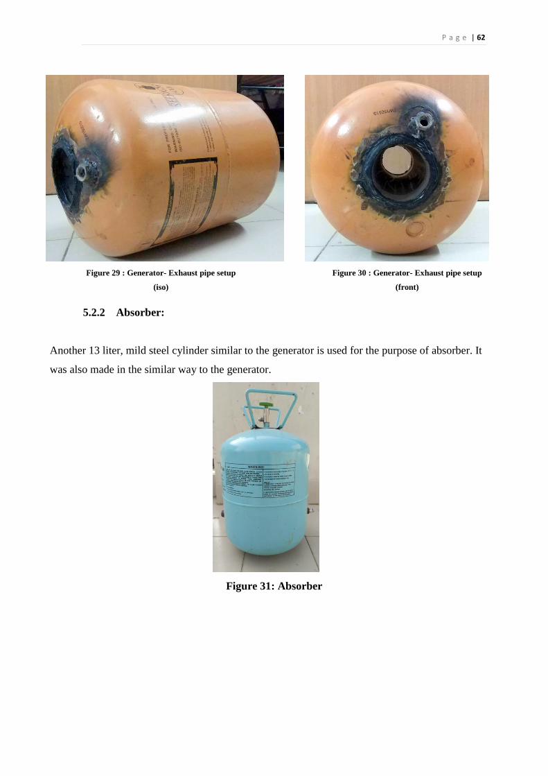
P a g e | 62
Figure 29 : Generator- Exhaust pipe setup
(iso)
Figure 30 : Generator- Exhaust pipe setup
(front)
5.2.2 Absorber:
Another 13 liter, mild steel cylinder similar to the generator is used for the purpose of absorber. It
was also made in the similar way to the generator.
Figure 31: Absorber
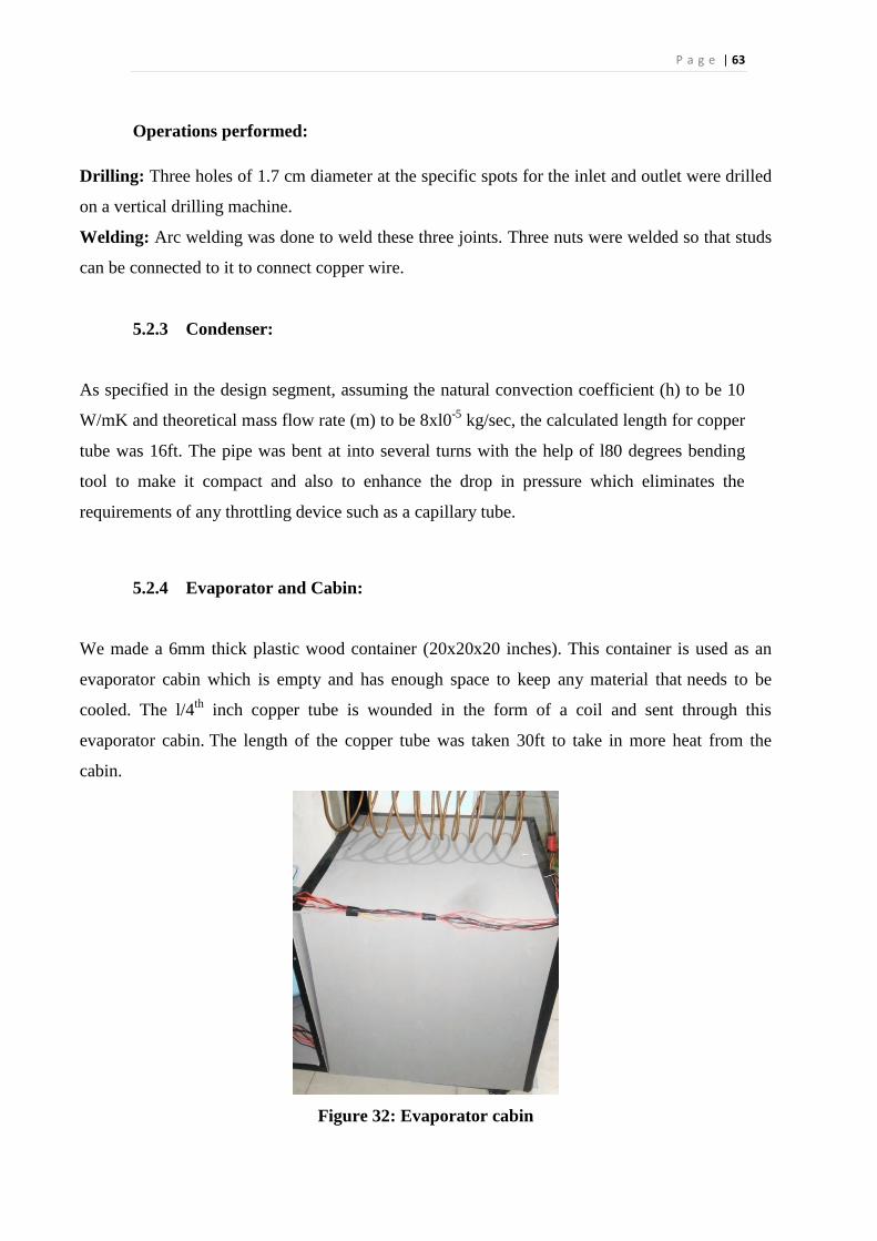
P a g e | 63
Operations performed:
Drilling: Three holes of 1.7 cm diameter at the specific spots for the inlet and outlet were drilled
on a vertical drilling machine.
Welding: Arc welding was done to weld these three joints. Three nuts were welded so that studs
can be connected to it to connect copper wire.
5.2.3 Condenser:
As specified in the design segment, assuming the natural convection coefficient (h) to be 10
W/mK and theoretical mass flow rate (m) to be 8xl0-5
kg/sec, the calculated length for copper
tube was 16ft. The pipe was bent at into several turns with the help of l80 degrees bending
tool to make it compact and also to enhance the drop in pressure which eliminates the
requirements of any throttling device such as a capillary tube.
5.2.4 Evaporator and Cabin:
We made a 6mm thick plastic wood container (20x20x20 inches). This container is used as an
evaporator cabin which is empty and has enough space to keep any material that needs to be
cooled. The l/4th
inch copper tube is wounded in the form of a coil and sent through this
evaporator cabin. The length of the copper tube was taken 30ft to take in more heat from the
cabin.
Figure 32: Evaporator cabin
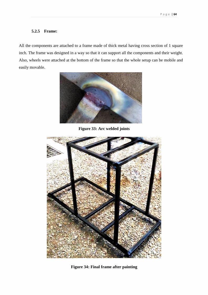
P a g e | 64
5.2.5 Frame:
All the components are attached to a frame made of thick metal having cross section of 1 square
inch. The frame was designed in a way so that it can support all the components and their weight.
Also, wheels were attached at the bottom of the frame so that the whole setup can be mobile and
easily movable.
Figure 33: Arc welded joints
Figure 34: Final frame after painting
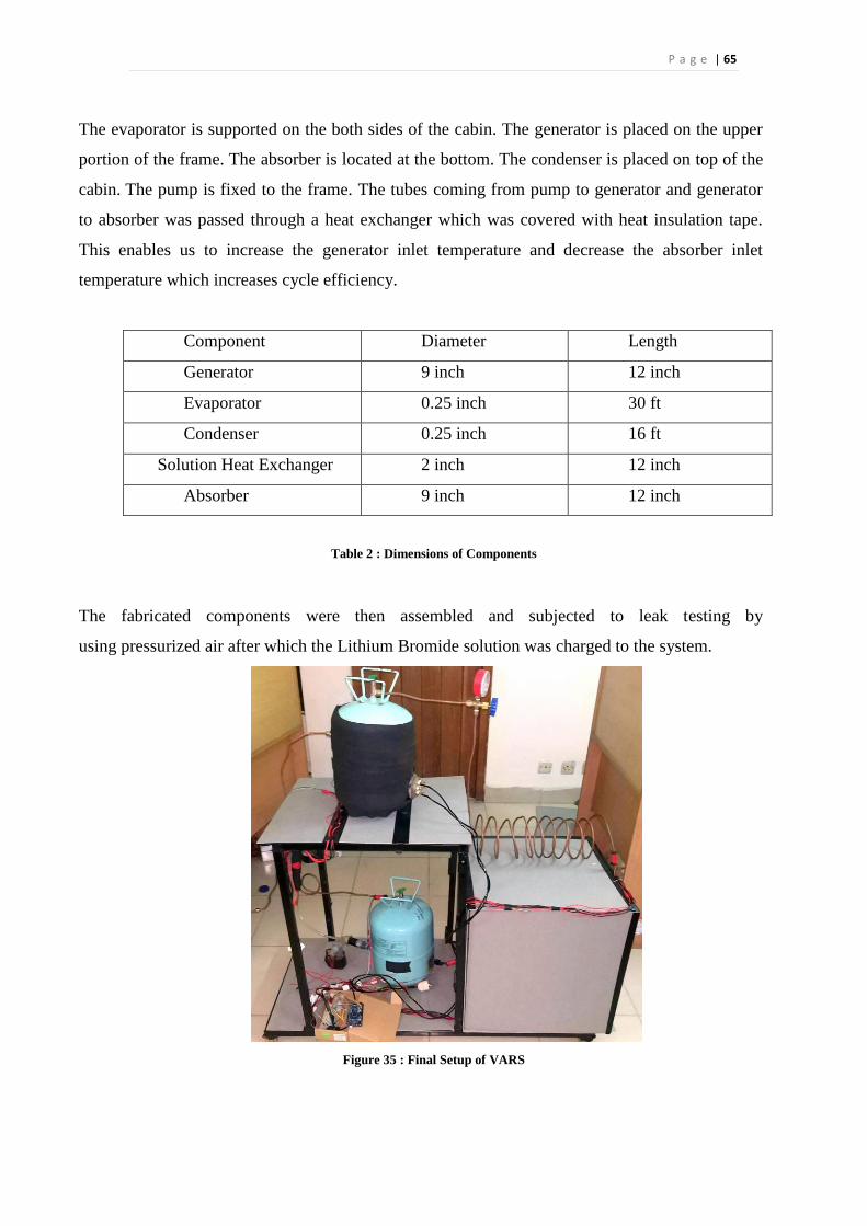
P a g e | 65
The evaporator is supported on the both sides of the cabin. The generator is placed on the upper
portion of the frame. The absorber is located at the bottom. The condenser is placed on top of the
cabin. The pump is fixed to the frame. The tubes coming from pump to generator and generator
to absorber was passed through a heat exchanger which was covered with heat insulation tape.
This enables us to increase the generator inlet temperature and decrease the absorber inlet
temperature which increases cycle efficiency.
Component Diameter Length
Generator 9 inch 12 inch
Evaporator 0.25 inch 30 ft
Condenser 0.25 inch 16 ft
Solution Heat Exchanger 2 inch 12 inch
Absorber 9 inch 12 inch
Table 2 : Dimensions of Components
The fabricated components were then assembled and subjected to leak testing by
using pressurized air after which the Lithium Bromide solution was charged to the system.
Figure 35 : Final Setup of VARS
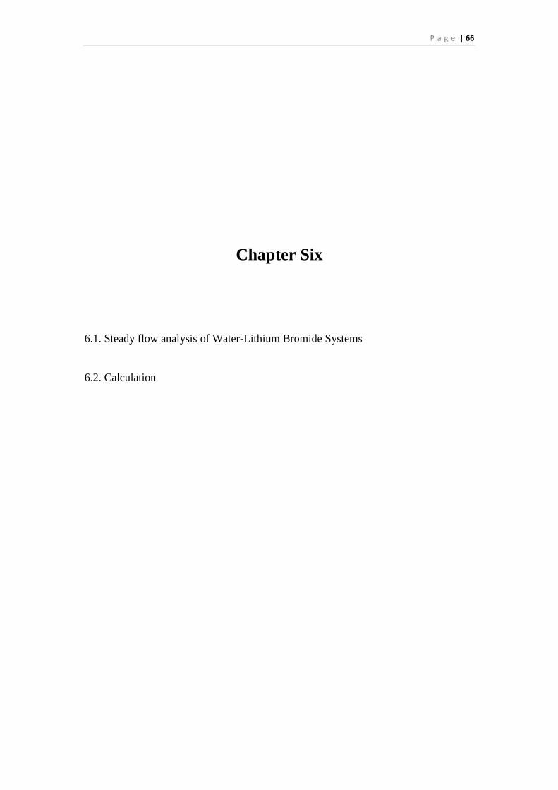
P a g e | 66
Chapter Six
6.1. Steady flow analysis of Water-Lithium Bromide Systems
6.2. Calculation
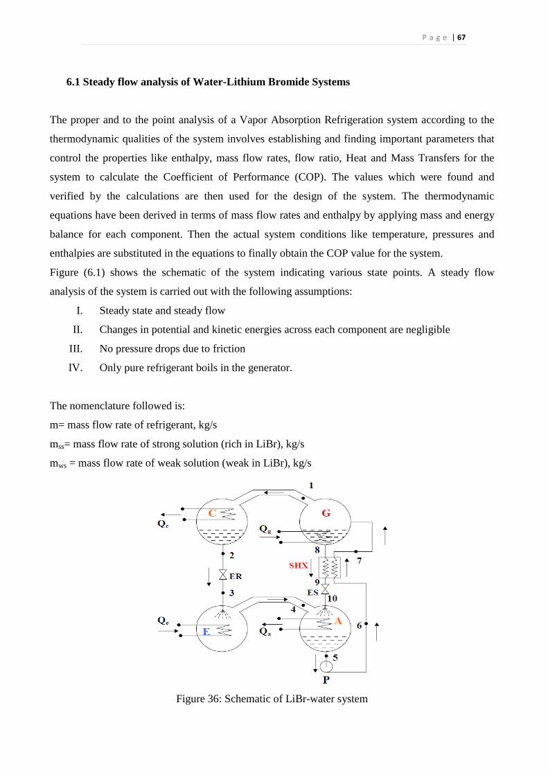
P a g e | 67
6.1 Steady flow analysis of Water-Lithium Bromide Systems
The proper and to the point analysis of a Vapor Absorption Refrigeration system according to the
thermodynamic qualities of the system involves establishing and finding important parameters that
control the properties like enthalpy, mass flow rates, flow ratio, Heat and Mass Transfers for the
system to calculate the Coefficient of Performance (COP). The values which were found and
verified by the calculations are then used for the design of the system. The thermodynamic
equations have been derived in terms of mass flow rates and enthalpy by applying mass and energy
balance for each component. Then the actual system conditions like temperature, pressures and
enthalpies are substituted in the equations to finally obtain the COP value for the system.
Figure (6.1) shows the schematic of the system indicating various state points. A steady flow
analysis of the system is carried out with the following assumptions:
I. Steady state and steady flow
II. Changes in potential and kinetic energies across each component are negligible
III. No pressure drops due to friction
IV. Only pure refrigerant boils in the generator.
The nomenclature followed is:
m= mass flow rate of refrigerant, kg/s
mss= mass flow rate of strong solution (rich in LiBr), kg/s
mws = mass flow rate of weak solution (weak in LiBr), kg/s
Figure 36: Schematic of LiBr-water system
P a g e | 68
A: Absorber; C: Condenser; E: Evaporator; G: Generator; P: Solution pump
SHX: Solution HX; ER: Refrigerant Expansion valve;
ES: Solution Expansion valve
The circulation ratio (λ) is defined as the ratio of strong solution flow rate to
refrigerant flow rate. It is given by:
λ = mss/m (6.1a)
This implies that the strong solution flow rate is given by:
mss =λm (6.1b)
The analysis is carried out by applying mass and energy balance across each
component.
Condenser:
m1 = m2 = m (6.1c)
Qc = m (h1-h2) (6.1d)
Pc = Psat (Tc) (6.1e)
where Tc is the condenser temperature.
Expansion valve (refrigerant):
m2 = m3 =m (6.1f)
h2 = h3 (6.1g)
Evaporator:
m3= m4 =m (6.1h)
Qe = m (h4 - h3) (6.1i)
Pe = Psat (Te) (6.1j)
where Te is the evaporator temperature.
Absorber:
From heat balance:
Qa = mh4+ mssh10 - mwsh6
From total mass balance:
P a g e | 69
m + mss = mws
And, mss = m λ
So, mws = (1+ λ) m (6.1k)
For mass balance for pure water:
𝑚 + (1 − 𝜉𝑠𝑠 )𝑚𝑠𝑠 = (1 − 𝜉𝑤𝑠)𝑚𝑤𝑠
𝜆 = 𝜉𝑤𝑠 /( 𝜉𝑠𝑠 − 𝜉𝑤𝑠) (6.1l)
𝑄𝑎 = 𝑚ℎ4 + 𝜆 𝑚ℎ10 − (1 + 𝜆)𝑚ℎ5 (6.1m)
Or, 𝑄𝑎 = 𝑚[(ℎ4 − ℎ5)+ 𝜆(ℎ10 − ℎ5) (6.1n)
The first term in the above equation m(h4 -h5)represents the enthalpy change of water
as changes its state from vapor at state 4 to liquid at state 5. The second term m λ
(h10-h5) represents the sensible heat transferred as solution at state 10 is cooled to
solution at state 5.
Solution pump:
m5 = m6 = mws (6.1o)
𝑊𝑝 = 𝑚𝑤𝑠(ℎ6 − ℎ5) = (1 + 𝜆) 𝑚(ℎ6 − ℎ5) (6.1p)
However, if we assume the solution to be incompressible, then:
𝑊𝑝 = (1 + 𝜆)𝑚𝑣𝑠𝑜𝑙(𝑝6 − 𝑝5) = (1 + 𝜆)𝑚𝑣𝑠𝑜𝑙(𝑝𝑐 − 𝑝𝑒) (6.1q)
Where vsol
is the specific volume of the solution, which can be taken to be
approximately equal to 0.00055m3
/kg. Even though the solution pump work is small
it is still required in the selection of suitable pump.
Solution heat exchanger:
m6 = m7 =mws (6.1r)
m8= m9 = mss (6.1s)
Heat transfer rate in the solution heat exchanger, QHX is given by:
𝑄𝐻𝑋 = (1 + 𝜆)𝑚(ℎ7 − ℎ6) = 𝜆𝑚(ℎ8 − ℎ9) (6.1t)
From heat balance Qhx = mws (h7 - h6)
P a g e | 70
Generator:
From heat balance:
Qg = mh1 + mssh8 - mwsh7
m7 = m8 + m1 (6.1u)
Heat input to the generator is given by:
𝑄𝑔 = 𝑚ℎ1 + 𝜆𝑚ℎ8 − (1 + 𝜆)𝑚ℎ7 (6.1v)
Or,𝑄𝑔 = 𝑚[(ℎ1 − ℎ7) + 𝜆(ℎ8 − ℎ7)] (6.1w)
In the above equation the 1st
term on the RHS m (h1-h7) represents energy required to
generate water vapor at state 1 from solution at state 7 and the 2nd
term mλ(h8-h7)
represents the sensible heat required to heat the solution from state 7 to state 8.
Solution expansion valve:
m9 = m10 = mws (6.1x)
h9 = h10
The COP of the system is given by:
COP= Qe/ (Qg + Wp ) ≈ Qe / Qg (6.1y)
6.2 Calculation
6.2.1 Theoretical Calculation:
Evaporator Temperature, T4 = 22℃
Condenser Temperature, T2 = 50℃
Absorber Temperature, T5 = 30℃
Generator Temperature, T1 = 70℃
At 50℃ temperature saturation pressure is 12.34Kpa (from Table: 6)
At 22℃ temperature saturation pressure is 2.642Kpa (from Table: 6)
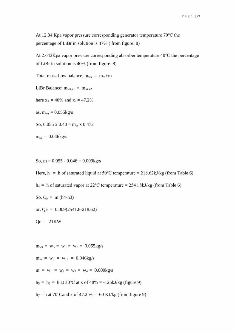
P a g e | 71
At 12.34 Kpa vapor pressure corresponding generator temperature 70℃ the
percentage of LiBr in solution is 47% ( from figure: 8)
At 2.642Kpa vapor pressure corresponding absorber temperature 40℃ the percentage
of LiBr in solution is 40% (from figure: 8)
Total mass flow balance, mws = mss+m
LiBr Balance: mws,x1 = mss,x2
here x1 = 40% and x2 = 47.2%
as, mws = 0.055kg/s
So, 0.055 x 0.40 = mss x 0.472
mss = 0.046kg/s
So, m = 0.055 - 0.046 = 0.009kg/s
Here, h3 = h of saturated liquid at 50℃ temperature = 218.62kJ/kg (from Table 6)
h4 = h of saturated vapor at 22℃ temperature = 2541.8kJ/kg (from Table 6)
So, Qe = m (h4-h3)
or, Qe = 0.009(2541.8-218.62)
Qe = 21KW
mws = w5 = w6 = w7 = 0.055kg/s
mss = w8 = w10 = 0.046kg/s
m = w1 = w2 = w3 = w4 = 0.009kg/s
h5 = h6 = h at 30℃ at x of 40% = -125kJ/kg (figure 9)
h7 = h at 70℃and x of 47.2 % = -60 KJ/kg (from figure 9)
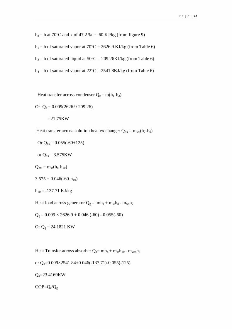
P a g e | 72
h8 = h at 70℃ and x of 47.2 % = -60 KJ/kg (from figure 9)
h1 = h of saturated vapor at 70℃ = 2626.9 KJ/kg (from Table 6)
h2 = h of saturated liquid at 50℃ = 209.26KJ/kg (from Table 6)
h4 = h of saturated vapor at 22℃ = 2541.8KJ/kg (from Table 6)
Heat transfer across condenser Qc = m(h1-h2)
Or Qc = 0.009(2626.9-209.26)
=21.75KW
Heat transfer across solution heat ex changer Qhx = mws(h7-h6)
Or Qhx = 0.055(-60+125)
or Qhx = 3.575KW
Qhx = mss(h8-h10)
3.575 = 0.046(-60-h10)
h10 = -137.71 KJ/kg
Heat load across generator Qg = mh1 + mssh8 - mwsh7
Qg = 0.009 × 2626.9 + 0.046 (-60) - 0.055(-60)
Or Qg = 24.1821 KW
Heat Transfer across absorber Qa= mh4 + mssh10 - mwssh6
or Qa=0.009×2541.84+0.046(-137.71)-0.055(-125)
Qa=23.4169KW
COP=Qe/Qg
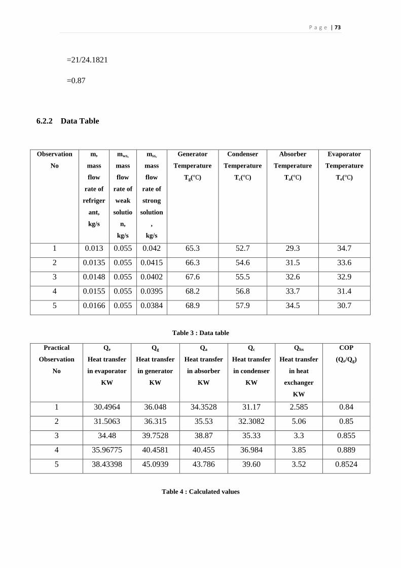
P a g e | 73
=21/24.1821
=0.87
6.2.2 Data Table
Observation
No
m,
mass
flow
rate of
refriger
ant,
kg/s
mws,
mass
flow
rate of
weak
solutio
n,
kg/s
mss,
mass
flow
rate of
strong
solution
,
kg/s
Generator
Temperature
Tg(℃)
Condenser
Temperature
Tc(℃)
Absorber
Temperature
Ta(℃)
Evaporator
Temperature
Te(℃)
1 0.013 0.055 0.042 65.3 52.7 29.3 34.7
2 0.0135 0.055 0.0415 66.3 54.6 31.5 33.6
3 0.0148 0.055 0.0402 67.6 55.5 32.6 32.9
4 0.0155 0.055 0.0395 68.2 56.8 33.7 31.4
5 0.0166 0.055 0.0384 68.9 57.9 34.5 30.7
Table 3 : Data table
Practical
Observation
No
Qe
Heat transfer
in evaporator
KW
Qg
Heat transfer
in generator
KW
Qa
Heat transfer
in absorber
KW
Qc
Heat transfer
in condenser
KW
Qhx
Heat transfer
in heat
exchanger
KW
COP
(Qe/Qg)
1 30.4964 36.048 34.3528 31.17 2.585 0.84
2 31.5063 36.315 35.53 32.3082 5.06 0.85
3 34.48 39.7528 38.87 35.33 3.3 0.855
4 35.96775 40.4581 40.455 36.984 3.85 0.889
5 38.43398 45.0939 43.786 39.60 3.52 0.8524
Table 4 : Calculated values
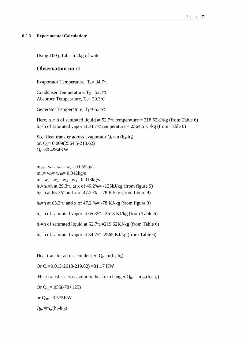
P a g e | 74
6.2.3 Experimental Calculation:
Using 100 g Libr in 2kg of water
Observation no :1
Evaporator Temperature, T4= 34.7℃
Condenser Temperature, T2= 52.7℃
Absorber Temperature, T5= 29.3℃
Generator Temperature, T1=65.3℃
Here, h3= h of saturated liquid at 52.7℃ temperature = 218.62kJ/kg (from Table 6)
h4=h of saturated vapor at 34.7℃ temperature = 2564.5 kJ/kg (from Table 6)
So, Heat transfer across evaporator Qe=m (h4-h3)
or, Qe= 0.009(2564.5-218.62)
Qe=30.4964KW
mws= w5= w6= w7= 0.055kg/s
mss= w8= w10= 0.042kg/s
m= w1= w2= w3= w4= 0.013kg/s
h5=h6=h at 29.3℃ at x of 40.2%= -125kJ/kg (from figure 9)
h7=h at 65.3℃ and x of 47.2 %= -78 KJ/kg (from figure 9)
h8=h at 65.3℃ and x of 47.2 %= -78 KJ/kg (from figure 9)
h1=h of saturated vapor at 65.3℃ =2618 KJ/kg (from Table 6)
h2=h of saturated liquid at 52.7℃=219.62KJ/kg (from Table 6)
h4=h of saturated vapor at 34.7℃=2565 KJ/kg (from Table 6)
Heat transfer across condenser Qc=m(h1-h2)
Or Qc=0.013(2618-219.62) =31.17 KW
Heat transfer across solution heat ex changer Qhx = mws(h7-h6)
Or Qhx=.055(-78+125)
or Qhx= 3.575KW
Qhx=mss(h8-h10)
P a g e | 75
3.575=.046(-78-h10)
h10=-137.71 KJ/kg
Heat load across generator Qg=mh1+mssh8 -mwsh7
Qg=0.013 ×2618 +0.042 (-78)-0.055(-78)
Or Qg=36.048 KW
Heat Transfer across absorber Qa= mh4+ mssh10- mwssh6
or Qa=0.013×2564.5+0.042(-139.54)-0.055(-125)
Qa=34.3528KW
COP=Qe/Qg
=30/36.048
=0.84
Observation no :2
Evaporator Temperature, T4= 33.6℃
Condenser Temperature, T2= 54.6℃
Absorber Temperature, T5= 31.5℃
Generator Temperature, T1=66.3℃
Here, h3=h of saturated liquid at 54.℃6 temperature = 228.4kJ/kg (from Table 6)
h4=h of saturated vapor at 33.6℃ temperature = 2562.2 kJ/kg (from Table 6)
So, Heat transfer across evaporator Qe=m (h4-h3)
or, Qe= 0.009(2562.2-228.4)
Qe=31.5063KW
mws=w5=w6=w7=0.055kg/s
mss=w8=w10=0.0415kg/s
m=w1=w2=w3=w4=0.0135kg/s
h5=h6=h at 31.5℃ at x of 40.7%= -162kJ/kg (from figure 9)
h7=h at 66.3℃ and x of 43 %= -70 KJ/kg (from figure 9)
P a g e | 76
h8=h at 65.3℃ and x of 43 %= -70 KJ/kg (from figure 9)
h1=h of saturated vapor at 66.3℃ =2620.2 KJ/kg (from Table 6)
h2=h of saturated liquid at 54.6℃=227KJ/kg (from Table 6)
h4=h of saturated vapor at 33.6℃=2562 KJ/kg (from Table 6)
Heat transfer across condenser Qc=m(h1-h2)
OrQc=0.013(2620.2-227)
=32.3082 KW
Heat transfer across solution heat ex changer Qhx = mws(h7-h6)
Or Qhx=.055(-70+162)
or Qhx= 5.06KW
Qhx=mss(h8-h10)
5.06=.0415(-70-h10)
h10=-191.92 KJ/kg
Heat load across generator Qg=mh1+mssh8 -mwsh7
Qg=0.0135 ×2620.2 +0.0415 (-70)-0.055(-70)
Or Qg=37.315 KW
Heat Transfer across absorber Qa= mh4+ mssh10- mwssh6
or Qa=0.0135×2562+0.0415(-191.92)-0.055(-162)
Qa=35.53KW
COP=Qe/Qg
=31.5063/36.315
=0.85
P a g e | 77
Observation no :3
Evaporator Temperature, T4= 32.9℃
Condenser Temperature, T2= 55.5℃
Absorber Temperature, T5= 32.6℃
Generator Temperature, T1=67.6℃
Here, h3=h of saturated liquid at 55.5℃ temperature = 230.98kJ/kg (from Table 6)
h4=h of saturated vapor at 32.9℃ temperature = 2561 kJ/kg (from Table 6)
So, Heat transfer across evaporator Qe=m (h4-h3)
or, Qe= 0.0148(2561-230.98)
Qe=34.48KW
mws=w5=w6=w7=0.055kg/s
mss=w8=w10=0.0402kg/s
m=w1=w2=w3=w4=0.0148kg/s
h5=h6=h at 32.6℃ at x of 40.4%= -125kJ/kg (from figure 9)
h7=h at 67.6℃ and x of 44 %= -65 KJ/kg (from figure 9)
h8=h at 67.6℃ and x of 44 %= -65 KJ/kg (from figure 9)
h1=h of saturated vapor at 67.6℃ =2621 KJ/kg (from Table 6)
h2=h of saturated liquid at 55.5℃=233.4KJ/kg (from Table 6)
h4=h of saturated vapor at 32.9℃=2562 KJ/kg (from Table 6)
Heat transfer across condenser Qc=m(h1-h2)
OrQc=0.0148(2621-233.4)
=35.33 KW
Heat transfer across solution heat ex changer Qhx = mws(h7-h6)
Or Qhx=.055(-65+125)
or Qhx= 3.3KW
Qhx=mss(h8-h10)
3.3=.0402(-65-h10)
h10= -147.08 KJ/kg
P a g e | 78
Heat load across generator Qg=mh1+mssh8 -mwsh7
Qg=0.0148×2621 +0.0402 (-65)-0.055(-65)
Or Qg=39.7528 KW
Heat Transfer across absorber Qa= mh4+ mssh10- mwssh6
or Qa=0.0148×2562+0.0402(-147.08)-0.055(-125)
Qa=38.87KW
COP=Qe/Qg
=34.48/39.7528
=0.855
Observation no :4
Evaporator Temperature, T4= 31.4℃
Condenser Temperature, T2= 56.8℃
Absorber Temperature, T5= 33.7℃
Generator Temperature, T1=68.2℃
Here, h3=h of saturated liquid at 56.8℃ temperature = 237.8kJ/kg (from Table 6)
h4=h of saturated vapor at 31.4℃ temperature = 2558 kJ/kg (from Table 6)
So, Heat transfer across evaporator Qe=m (h4-h3)
or, Qe= 0.0155(2558-237.8)
Qe=35.96775KW
mws=w5=w6=w7=0.055kg/s
mss=w8=w10=0.0395kg/s
m=w1=w2=w3=w4=0.0155kg/s
h5=h6=h at 33.7℃ at x of 40.1%= -122kJ/kg (from figure 9)
h7=h at 68.2℃ and x of 42 %= -52 KJ/kg (from figure 9)
h8=h at 68.2℃ and x of 42 %= -52 KJ/kg (from figure 9)
h1=h of saturated vapor at 68.℃2 =2623 KJ/kg (from Table 6)
h2=h of saturated liquid at 56.8℃=237.3KJ/kg (from Table 6)
h4=h of saturated vapor at 31.4℃=2558 KJ/kg (from Table 6)

P a g e | 79
Heat transfer across condenser Qc=m(h1-h2)
OrQc=.0155(2623-237.3)
=36.984 KW
Heat transfer across solution heat ex changer Qhx = mws(h7-h6)
Or Qhx=.055(-52+122)
or Qhx= 3.85 KW
Qhx=mss (h8-h10)
3.85=.0395(-52-h10)
h10= -149.46 KJ/kg
Heat load across generator Qg=mh1+mssh8 -mwsh7
Qg=0.0155×2558+0.0395 (-149.46)-0.055(-122)
Or Qg=40.455 KW
Heat Transfer across absorber Qa= mh4+ mssh10- mwssh6
or Qa=0.0155×2558.2+0.0395(-52)-0.055(-52)
Qa= 40.4581KW
COP=Qe/Qg
=35.96775/40.4581
=0.889
Observation no :5
Evaporator Temperature, T4= 30.7℃
Condenser Temperature, T2= 57.9℃
Absorber Temperature, T5= 34.5℃
Generator Temperature, T1=68.9℃
Here, h3=h of saturated liquid at 57.9℃ temperature = 242.3kJ/kg (from Table 6)
h4=h of saturated vapor at 30.7℃ temperature = 2557.6 kJ/kg (from Table 6)
So, Heat transfer across evaporator Qe=m (h4-h3)
or, Qe= 0.0166(2557.6-242.3)
P a g e | 80
Qe=38.43398KW
mws=w5=w6=w7=0.055kg/s
mss=w8=w10=0.0384kg/s
m=w1=w2=w3=w4=0.0166kg/s
h5=h6=h at 34.5℃ at x of 40.25%= -156kJ/kg (from figure 9)
h7=h at 68.9℃ and x of 41.2 %= -92 KJ/kg (from figure 9)
h8=h at 68.9℃ and x of 41.2 %= -92 KJ/kg (from figure 9)
h1=h of saturated vapor at 68.9℃ =2624.5 KJ/kg (from Table 6)
h2=h of saturated liquid at 57.9℃=238 KJ/kg (from Table 6)
h4=h of saturated vapor at 30.7℃=2557.9 KJ/kg (from Table 6)
Heat transfer across condenser Qc=m(h1-h2)
OrQc=.0166(2624.5-238.4)
=39.60 KW
Heat transfer across solution heat ex changer Qhx = mws(h7-h6)
Or Qhx=.055(-92+156)
or Qhx= 3.52 KW
Qhx=mss (h8-h10)
3.52=.0384(-92-h10)
h10= -183.67 KJ/kg
Heat load across generator Qg=mh1+mssh8 -mwsh7
Qg=0.0166×2624.5+0.0384 (-92)-0.055(-92)
Or Qg=45.0939 KW
Heat Transfer across absorber Qa= mh4+ mssh10- mwssh6
or Qa=0.0166×2557.9+0.0395(-183.67)-0.055(-156)
Qa= 43.786KW
COP=Qe/Qg
=38.43/45.0939 = 0.8524
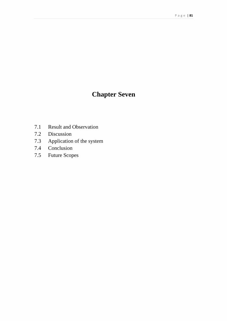
P a g e | 81
Chapter Seven
7.1 Result and Observation
7.2 Discussion
7.3 Application of the system
7.4 Conclusion
7.5 Future Scopes
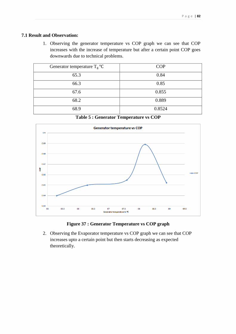
P a g e | 82
7.1 Result and Observation:
1. Observing the generator temperature vs COP graph we can see that COP
increases with the increase of temperature but after a certain point COP goes
downwards due to technical problems.
Generator temperature Tg ℃ COP
65.3 0.84
66.3 0.85
67.6 0.855
68.2 0.889
68.9 0.8524
Table 5 : Generator Temperature vs COP
Figure 37 : Generator Temperature vs COP graph
2. Observing the Evaporator temperature vs COP graph we can see that COP
increases upto a certain point but then starts decreasing as expected
theoretically.
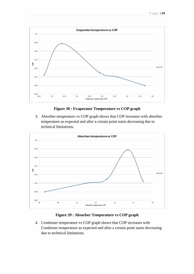
P a g e | 83
Figure 38 : Evaporator Temperature vs COP graph
3. Absorber temperature vs COP graph shows that COP increases with absorber
temperature as expected and after a certain point starts decreasing due to
technical limitations.
Figure 39 : Absorber Temperature vs COP graph
4. Condenser temperature vs COP graph shows that COP increases with
Condenser temperature as expected and after a certain point starts decreasing
due to technical limitations.
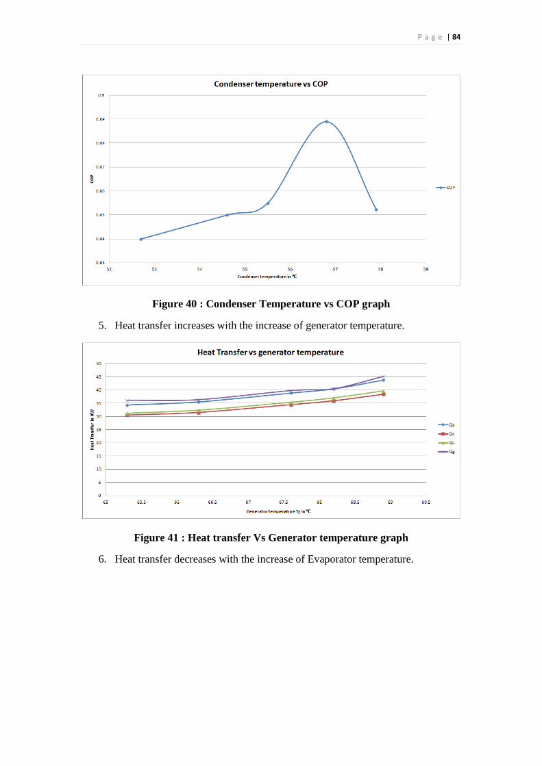
P a g e | 84
Figure 40 : Condenser Temperature vs COP graph
5. Heat transfer increases with the increase of generator temperature.
Figure 41 : Heat transfer Vs Generator temperature graph
6. Heat transfer decreases with the increase of Evaporator temperature.
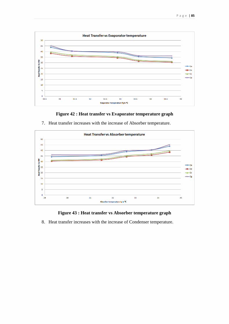
P a g e | 85
Figure 42 : Heat transfer vs Evaporator temperature graph
7. Heat transfer increases with the increase of Absorber temperature.
Figure 43 : Heat transfer vs Absorber temperature graph
8. Heat transfer increases with the increase of Condenser temperature.
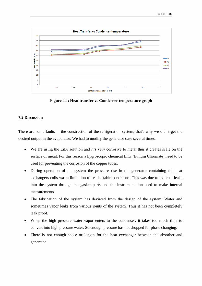
P a g e | 86
Figure 44 : Heat transfer vs Condenser temperature graph
7.2 Discussion
There are some faults in the construction of the refrigeration system, that's why we didn't get the
desired output in the evaporator. We had to modify the generator case several times.
We are using the LiBr solution and it’s very corrosive to metal thus it creates scale on the
surface of metal. For this reason a hygroscopic chemical LiCr (lithium Chromate) need to be
used for preventing the corrosion of the copper tubes.
During operation of the system the pressure rise in the generator containing the heat
exchangers coils was a limitation to reach stable conditions. This was due to external leaks
into the system through the gasket parts and the instrumentation used to make internal
measurements.
The fabrication of the system has deviated from the design of the system. Water and
sometimes vapor leaks from various joints of the system. Thus it has not been completely
leak proof.
When the high pressure water vapor enters to the condenser, it takes too much time to
convert into high pressure water. So enough pressure has not dropped for phase changing.
There is not enough space or length for the heat exchanger between the absorber and
generator.
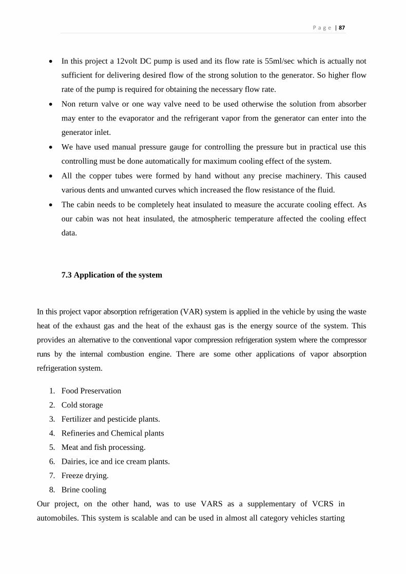
P a g e | 87
In this project a 12volt DC pump is used and its flow rate is 55ml/sec which is actually not
sufficient for delivering desired flow of the strong solution to the generator. So higher flow
rate of the pump is required for obtaining the necessary flow rate.
Non return valve or one way valve need to be used otherwise the solution from absorber
may enter to the evaporator and the refrigerant vapor from the generator can enter into the
generator inlet.
We have used manual pressure gauge for controlling the pressure but in practical use this
controlling must be done automatically for maximum cooling effect of the system.
All the copper tubes were formed by hand without any precise machinery. This caused
various dents and unwanted curves which increased the flow resistance of the fluid.
The cabin needs to be completely heat insulated to measure the accurate cooling effect. As
our cabin was not heat insulated, the atmospheric temperature affected the cooling effect
data.
7.3 Application of the system
In this project vapor absorption refrigeration (VAR) system is applied in the vehicle by using the waste
heat of the exhaust gas and the heat of the exhaust gas is the energy source of the system. This
provides an alternative to the conventional vapor compression refrigeration system where the compressor
runs by the internal combustion engine. There are some other applications of vapor absorption
refrigeration system.
1. Food Preservation
2. Cold storage
3. Fertilizer and pesticide plants.
4. Refineries and Chemical plants
5. Meat and fish processing.
6. Dairies, ice and ice cream plants.
7. Freeze drying.
8. Brine cooling
Our project, on the other hand, was to use VARS as a supplementary of VCRS in
automobiles. This system is scalable and can be used in almost all category vehicles starting
P a g e | 88
from Sedan to Trucks. This type of system is especially applicable in tropical country like
Bangladesh, where the weather is typically warm most the time of a year.
7.4 Conclusion
An absorption refrigeration cycle employing a lithium bromide-water solution as the working fluid
has been investigated in this work for purpose of cooling of a vehicle’s cabin. A low temperature
heat source for absorption cooling units has been also examined. At first, theoretical absorption
refrigeration systems were described and fully analyzed using both the first law and the second law
of thermodynamics. An aqueous LiBr absorption cooling cycle, with hot water as a heat source and
cooling water as a heat sink was then designed and fabricated. The optimization study of the cycle
was made in relation to the parameter of solution heat exchanger effectiveness, and operating
temperatures of the generator, condenser, absorber and evaporator as well as to the temperatures of
the environment and the external fluids (hot water, cooling water and chilled water). To accomplish
this objective, temperature sensors, flow sensors, pressure gauge, pressure release valve and a
controlling unit (Arduino) are used to get various data for calculating the COP of the system. The
results of this study were then used to fix a practical thermodynamic cycle of operation. This, in
conjunction with mass and energy balances, enabled the calculation of the heat transfer areas in the
cycle components from appropriate heat transfer coefficients has been calculated. As a result the
generator, condenser, evaporator, absorber and solution pump have been designed. The mechanical
design of an experimental absorption refrigeration rig was then carried out and the fabrication of
system heat exchangers. Finally, a review of the system for absorption cooling has been presented
and methodologies have been discussed. Numerical results have been obtained for the performance
of supplying heat with a water heater to the absorption refrigeration system. Based on the results of
the investigations performed in this study, the concluding remarks are as follows.
Absorption refrigeration cycles can be analyzed and modelled by using the second law of
thermodynamics. The thermodynamic efficiency based on the lost work concept, as used in this
research, is a. simple way of evaluating the energy usage of absorption cooling cycles. It indicates
how much heat can be removed from the cooling load by an actual absorption refrigeration process
compared to the quantity of heat that would be removed by a totally reversible absorption cycle
accepting heating and cooling inputs at the same temperature levels.
P a g e | 89
COP and thermodynamic efficiency has been calculated with respect to a small cabin having a
dimension of 20*20*20 and the result of its parametric variation for a LiBr-water cooling cycle
show that there are many ways at hand for designing an improved and more efficient system. The
different modifications which can be made to reduce the system lost work and increase the second
law efficiency have been discussed in chapter 5. The findings of the theoretical evaluation of LiBr -
water absorption refrigeration cycles have been used to define a practical thermodynamic cycle
operation. After fabrication of the total system with traditional drilling, cutting and welding
techniques it was found that hermeticity of LiBr-water absorption units is difficult to achieve unless
special care is taken in the design of static seals and in the machining of grooves which receive the
seals.
7.5 Future Scopes
1. During operation of the system the pressure rise in the generator containing the heat
exchangers coils was a limitation to reach stable conditions. This was due to external leaks
into the system through the gasket parts and the instrumentation used to make internal
measurements.
2. Further work is required in order to verify the results of the theoretical analysis and
optimization of a LiBr-water absorption refrigeration system for cooling the vehicle cabin.
Experimental data need to be accumulated correctly to calculate system capacity, COP,
second law efficiency, heat fluxes and heat transfer coefficients in the various components.
3. Research needs to be done to try to reduce the temperature differences between the internal
and external fluids in the absorption cycle without considerable increase in heat transfer
areas and/or in mass flow rates.
4. Consideration should be given to the application of analysis and optimization through lost
work not only to the absorption refrigeration cycle but also to the streams of external fluids
(hot water, cooling water and possibly chilled water). These are not free sources and sinks
and therefore should be utilized with an improved and efficient operation.
5. Further theoretical and practical research is necessary to develop new absorption
refrigeration units with high efficiencies. Innovative heat transfer configurations should be
conceived and proven. Description of basic design rules which allow achieving high
efficiencies should be included. Reduction in size of heat exchangers is to be examined.|
P a g e | 90
References
1. http://www.academia.edu/2381262/Crystallization_Temperature_of_Aqueous_Lithium_Bromi
de_Solutions_at_Low_Evaporation_Temperature
2. http://www.slideshare.net/IanLouiseCelestino/intro-to-vapor-absorption-refrigeration-
system?qid=445b09d6-3f07-4eaf-a28e-bc8fd1086eff&v=&b=&from_search=2
3. https://www.google.com/url?sa=t&rct=j&q=&esrc=s&source=web&cd=2&cad=rja&uact=8&v
ed=0ahUKEwjv4pbcurPRAhWIOI8KHcyWCDkQFggfMAE&url=http%3A%2F%2Fnptel.ac.
in%2Fcourses%2FWebcourse-
contents%2FIIT%2520Kharagpur%2FRef%2520and%2520Air%2520Cond%2Fpdf%2FRAC
%2520Lecture%252014.pdf&usg=AFQjCNF2WwNuhqwgVL2-
QHlTqLBOodJl5g&bvm=bv.143423383,d.c2I
4. http://www.slideshare.net/AbhijeetSingh130/lbars-abhi?qid=dd9aa2c2-96ba-4f51-96e7-
8f5b355009e0&v=&b=&from_search=58
5. https://www.google.com/url?sa=t&rct=j&q=&esrc=s&source=web&cd=1&cad=rja&uact=8&v
ed=0ahUKEwiW6aGnvbPRAhUHMY8KHaQPCYsQFggZMAA&url=http%3A%2F%2Fnpte
l.ac.in%2Fcourses%2FWebcourse-
contents%2FIIT%2520Kharagpur%2FRef%2520and%2520Air%2520Cond%2Fpdf%2FRAC
%2520Lecture%252015.pdf&usg=AFQjCNFax3a36OG5yQwK0l1YZH_-
EK8hmg&bvm=bv.143423383,d.c2I
6. 5.http://www.slideshare.net/IanLouiseCelestino/advantages-and-disadvantages-of-vars
7. http://www.saitm.edu.lk/fac_of_eng/RSEA/SAITM_RSEA_2014/imagenesweb/2.pdf
8. Alizadeh; S., Bahar; F., and Geoola; F., 1979 “Design and Optimization of an Absorption
Refrigeration System Operated By Solar Energy ", Solar Energy, 22, 149- 154
9. P.Sathiamurthi, PSS.Srinivasan “Design and Development of Waste Heat Recovery System for
air Conditioning Unit, European Journal of Scientific Research,Vol.54 No.1 (2011), pp.102-110
P a g e | 91
10. M.M. Rahman, Chin WaiMeng& Adrian Ng, Air Conditioning & Water Heating – An
environmental friendly and cost effective way of waste heat recovery, AEESEAP Journal of
engineering education, 2007, Vol. 31, No.2
11. y.z.Lu, R.Z. Wang, S. Jianzhou, Y.X.Xu, J.Y.Wu (2004) Practical experiments on an adsorption
air conditioner powered by exhausted heat from diesel locomotive. Appl. Thermal Engg 24;
1051-1059.
12. S. Jiangzhou, R.Z Wang, Y.ZLu, Y.X.Xu, J.Y.Wu (2002) Experimental investigations on
adsorption air conditioner used in internal combustion locomotive driver cabin. Appl. Thermal
engg 22; 1153-1162.
13. R.E. Critoph(2000) The use of thermosyphon heat pipes to improve the performance of a carbon
ammonia adsorption refrigerator. proc. Of the IV Minsk Int. Seminar- Heat Pipes, Heat Pumps,
Refrigerator; Belarus.
14. M. Talbi and B. Agnew, “Energy recovery from diesel engine exhaust gases for performance
enhancement and air conditioning,” Applied Thermal Engineering 22 (2002) 693–702.
15. Fernández-Seara J, Sieres J. The Importance of the Ammonia Purification Process in Ammonia–
Water Absorption Systems. Energy Conversion and Managemnt 2006; 47: 1975–87.
16. Liu M, Zhang N. Proposal and Analysis of a Novel Ammonia–Water Cycle for Power and
Refrigeration Cogeneration. Energy 2007; 32: 961–70.
17. Christopher Taylor. Enveloping heat absorber for improved refrigerator efficiency and recovery
of reject heat for water heating, Febraury 2000. U.S. Patent number 6029471.
18. N. Hossain And S Bari, “Effect Of Design-Parameters Of Heat Exchanger On Recovering Heat
From Exhaust Of Diesel Engine Using Organic Rankine Cycle,” Proceedings of the International
Conference on Mechanical Engineering 2011 (ICME2011) 18-20 December 2011, Dhaka,
Bangladesh.
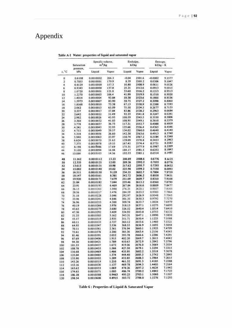
P a g e | 92
Appendix
Table 6 : Properties of Liquid & Saturated Vapor