Design and Experiments on a Novel Biomechatronic Hand
10
Design and Experiments on a Novel Biomechatronic Hand P. Dario, M.C. Carrozza, S. Micera, B. Massa, M. Zecca Mitech Lab, Scuola Superiore Sant’Anna 56127 Pisa, Italy Centro INAIL RTR 55049 Viareggio (LU), Italy E-mail: [email protected] Abstract: An “ideal” upper limb prosthesis should be perceived as part of the natural body by the amputee and should replicate sensory-motor capabilities of the amputated limb. However, such an ideal “cybernetic” prosthesis is still far from reality: current prosthetic hands are simple grippers with one or two degrees of freedom, which barely restore the capability of the thumb-index pinch. This paper describes the design and fabrication of a novel prosthetic hand based on a “biomechatronic” and cybernetic approach. Our approach is aimed at providing “natural” sensory-motor co-ordination to the amputee, by integrating biomimetic mechanisms, sensors, actuators and control, and by interfacing the hand with the peripheral nervous system. 1. Introduction The development of an upper limb prosthesis that can be felt as a part of the body by the amputee (Extended Physiological Proprioception – EPP [1]), and that can substitute the amputated limb by closely replicating its sensory-motor capabilities (“cybernetic” prosthesis [2]), is far to become reality. In fact, current commercial prosthetic hands are unable to provide enough grasping functionality and to provide sensory-motor information to the user. One of the main problems of the current available devices is the lack of degrees of freedom (DOFs). Commercially available prosthetic devices, such as Otto Bock SensorHand™, as well as multifunctional hand designs [3,4,5,6,7,8,9] are far from providing the manipulation capabilities of the human hand [10]. This is due to many different reasons. For example, in prosthetic hands active bending is restricted to two or three joints, which are actuated by a single motor drive acting simultaneously on the metacarpo-phalangeal (MP) joints of the thumb, of the index and of the middle finger, while other joints can bend only passively. The way to overcome all these problems is to develop a “cybernetic” prosthesis following a biomechatronic approach, i.e. by designing a mechatronic system inspired by the biological world. A cybernetic prosthesis must solve the following problems of the commercial prostheses: 1. the reduced grasping capabilities; 2. the noncosmetic appearance; 3. the lack of sensory information given to the amputee;
Transcript of Design and Experiments on a Novel Biomechatronic Hand

Design and Experiments on a Novel Biomechatronic Hand
P. Dario, M.C. Carrozza, S. Micera, B. Massa, M. Zecca Mitech Lab, Scuola Superiore Sant’Anna
56127 Pisa, Italy Centro INAIL RTR
55049 Viareggio (LU), Italy E-mail: [email protected]
Abstract: An “ideal” upper limb prosthesis should be perceived as part of the natural body by the amputee and should replicate sensory-motor capabilities of the amputated limb. However, such an ideal “cybernetic” prosthesis is still far from reality: current prosthetic hands are simple grippers with one or two degrees of freedom, which barely restore the capability of the thumb-index pinch. This paper describes the design and fabrication of a novel prosthetic hand based on a “biomechatronic” and cybernetic approach. Our approach is aimed at providing “natural” sensory-motor co-ordination to the amputee, by integrating biomimetic mechanisms, sensors, actuators and control, and by interfacing the hand with the peripheral nervous system.
1. Introduction The development of an upper limb prosthesis that can be felt as a part of the body by the amputee (Extended Physiological Proprioception – EPP [1]), and that can substitute the amputated limb by closely replicating its sensory-motor capabilities (“cybernetic” prosthesis [2]), is far to become reality. In fact, current commercial prosthetic hands are unable to provide enough grasping functionality and to provide sensory-motor information to the user. One of the main problems of the current available devices is the lack of degrees of freedom (DOFs).
Commercially available prosthetic devices, such as Otto Bock SensorHand™, as well as multifunctional hand designs [3,4,5,6,7,8,9] are far from providing the manipulation capabilities of the human hand [10]. This is due to many different reasons. For example, in prosthetic hands active bending is restricted to two or three joints, which are actuated by a single motor drive acting simultaneously on the metacarpo-phalangeal (MP) joints of the thumb, of the index and of the middle finger, while other joints can bend only passively.
The way to overcome all these problems is to develop a “cybernetic” prosthesis following a biomechatronic approach, i.e. by designing a mechatronic system inspired by the biological world. A cybernetic prosthesis must solve the following problems of the commercial prostheses:
1. the reduced grasping capabilities; 2. the noncosmetic appearance; 3. the lack of sensory information given to the amputee;

4. the lack of a “natural” command interface. The first and the second problems can be solved by increasing the number of
active and passive DOFs; this can be achieved by embedding a higher number of actuators in the hand structure and designing coupled joints.
The third and forth problems can be addressed by developing a “natural” interface between the Peripheral Nervous System (PNS) and the artificial device (i.e., a “natural” Neural Interface (NI)) to record and stimulate the PNS in a selective way. This can be useful in order to make possible the ENG-based control of the prosthesis (to solve the forth problem) and to give back some sensory feedback to the amputee by stimulating in an appropriate way his/her afferent nerves (after characterizing the afferent signals of the PNS in response to mechanical and proprioceptive stimuli) solving the third problem of the commercially-available hand prostheses. This approach is illustrated in Figure 1.
Design of a Biomechatronic
Hand
Design of a Neural Interface
Design of ENG Signal
Processing Techniques
Interfacing the natural and the artificial world
Design of a Cybernetic
Hand Figure 1. Approach for the development of a cybernetic hand
Current research activities at Scuola Superiore Sant’Anna aimed at the development of a biomechatronic prosthetic hand controlled through a “natural” NI are presented in this paper. In particular, preliminary results obtained in processing ENG signals from afferent nerves are illustrated and analyzed.
2. Design of the biomechatronic hand The main requirements to be considered since the very beginning of a prosthetic hand design are the following: cosmetics, controllability, noiselessness, lightness and low energy consumption. These requirements can be fulfilled by implementing an integrated design approach aimed at embedding different functions (mechanisms, actuation, sensing and control) within a housing closely replicating the shape, size and appearance of the human hand. This approach can be synthesized by the term: “biomechatronic” design [11].
2.1. Architecture of the biomechatronic hand The biomechatronic hand will be equipped with three actuator systems to provide a tripod grasping: two identical finger actuator systems and one thumb actuator system (see Figure 2).

Figure 2. Architecture of the biomechatronic hand.
The finger actuator system is based on two micro-actuators, which drives the MP and the PIP joints respectively; for cosmetic reasons, both actuators are fully integrated in the hand structure: the first in the palm and the second within the proximal phalange. The DIP joint is passively driven by a four bars link connected to the PIP joint. The thumb is equipped with two active DOFs in the MP joint and one driven passive DOF in the IP joint.
The grasping task is divided in two subsequent phases in which the two different actuator systems are active:
1) reaching and shape-adapting phases; 2) grasping phase with thumb opposition. In fact, in phase 1) the first actuator system allows the finger to adapt to the
morphological characteristics of the grasped object by means of a low output torque motor. In phase two, the thumb actuator system provides a power opposition force, useful to manage critical grasps, especially in case of heavy or slippery objects.
It is important to point out that the most critical problem of the proposed configuration is related to the strength required to micro-actuators to withstand the high load applied during the grasping phase.
In order to demonstrate the feasibility of the described biomechatronic approach, we started by developing one finger (index or middle).
2.2. Design and development of the finger prototype As outlined above, the two DOF finger prototype is designed by reproducing, as closely as possible, the size and kinematics of a human finger. It consists of three phalanges and of palm housing, which is the part of the palm needed to house the proximal actuator (see Figure 3).

Figure 3. Finger design.
Figure 4. Finger prototype.
In order to match the size of a human finger, two micro-motors are incorporated, respectively, in the palm and in the proximal phalange. The actuator system is based on Smoovy (RMB, Eckweg, CH) micro-drivers (5 mm diameter) linear actuators based on DC brushless motors.
The output force resulting from motor activation is sufficient to move the phalanges for achieving adaptive grasp. In addition, the shell housing provides mechanical resistance of the shaft to both axial and radial loads. This turns out to be essential during grasping tasks, where loads, derived from the thumb opposition, act both on the actuator system and on the whole finger structure.
A first prototype of the finger was fabricated using the Fused Deposition Modeling [FDM] process (see Figure 4). This process allows the fabrication in a single process of three-dimensional objects, made out of acrylonitrile/butadiene/styrene [ABS] resin, directly from CAD-generated solid models.
2.3. Fingertip force characterization A first set of experimental tests has been performed in order to evaluate the force that the finger is able to exert on an external object [12]. To this aim we have measured the force resulting when the finger is pressing directly on a force sensor (3-axial piezoelectric load cell 9251 A, Piezo-Instrumentation KISTLER, Kiwag, CH), corresponding to different configurations of the joints.
Two “pressing” tasks were identified in order to evaluate separately and independently force obtained by the two actuators incorporated in the finger:
TASK 1: the pushing action was exerted only by the distal actuator. TASK 2: the pushing action was exerted only by the proximal actuator.
Corresponding to each task, two subtasks were identified according to the position of the non-active joint (extended, flexed). The different values of joint rotation angles corresponding to each subtask are illustrated in Figure 5.

Figure 5. Positions of finger joints for each task.The active joint for each task and position is
indicated by a small circle.
During the force characterization the fingertip pushed on the force sensor. The Z force component was recorded, the X and Y outputs of the load cell were monitored. This was obtained by adjusting the finger position for obtaining a force parallel to the Z-axis of the load cell. A first set of experimental tests was done on the finger prototype, with the aim of evaluating how much force the finger is able to apply on an object.
2.4. Results and discussion Ten tests were performed for each subtask. The obtained results are illustrated in Figure 6. These force values are comparable with force exerted by “natural” human finger during fine manipulation, thus demonstrating the feasibility of the biomechatronic approach, at least for this class of manipulation tasks. The output force resulting from motor activation is sufficient to move the phalanges for achieving adaptive grasp [13].
Figure 6. Experimental results.
3. Development of an intelligent Neural Interface (NI) 3.1. Microelectrodes Array Fabrication
Different microelectrode arrays on silicon substrates (named "dice") were designed and fabricated using various microfabrication technologies. Three different dice designs were fabricated with different dimensions, electrode size, and through-holes dimensions. The designs mainly utilized for in vivo experiments were the so called “Active Die 1” and “Active Die 2”. A photograph of Active Die 2 is shown in Figure 7. Some dice did not incorporate electrodes (“passive dice”) and were used

for control purposes. In order to achieve mechanical robustness, each silicon die was mounted in a titanuim ring, fabricated by laser machining purposely to host the die and the electrical connections.
Figure 7. Active Die 2. Electrode size of 9x7,696 µm2, through holes dimensions of 24x24
µm2; center spacing 36 µm; total number of through-holes: 20x20; number of Ti-Pt electrodes is 10.
3.2. Electrophysiological Results
3.2.1. Electrophysiological Set-up and Methods In vivo tests were performed on adult female New Zealand rabbits. For control purposes a first set of experiments was performed using first empty guidance channels and then NI based on "passive" dice (i.e. dice with through-holes but no electrodes) with no interconnects. A second set of experiments was performed using complete NI incorporating active dice. The same surgical procedure was adopted for the two sets of experiments.
Different set-up configurations were used depending on the experiment performed. For recording from the intact nerve, from nerve regenerated in empty guidance channels and from nerve through passive dice, the sciatic nerve was stimulated proximally through a pair of electrodes (FHC Hook Electrodes # 06-11-2) with constant current pulses (duration = 0.08-0.1 ms) of different intensities. Responses for both anodic and cathodic stimulations were obtained. The electroneurogram (ENG) analysis was performed by measuring the compound action potential (CAP) from the recording electrodes (placed at a distance of 50 mm from the stimulation site). In animals implanted with the NI the connector was plugged to a standard electrophysiological set-up for nerve recording and stimulation. A mechanical switch allowed each of the 10 neural interface electrodes to be connected to the electronic apparatus.
Single pulses (amplitude range = 40 µA-1 mA, duration = 0.2 ms) were delivered at each of the 10 electrodes of the active interface. When muscle contraction was observed, thus indicating the presence of functional axons, the same channel of the neural interface used for stimulation was connected to the recording apparatus and the spontaneous nerve activity was monitored. Neural activity was also recorded in response to passive leg movements (i.e., stretching).
3.2.2. Computer Analysis of Electrophysiological Signals Signals from the amplifier were stored on a tape recorder and then played back and digitized on a computer hard disk (using a MIO-16 A/D converter). Suitable

programs, based on LabView programming techniques, were used in order to acquire experimental data and synchronize the electrical stimulation. The amplitude and delay of compound action potentials were measured in order to assess the functional recovery of the regenerated nerve.
3.2.3. Stimulation and Recording from Nerve Axons using NI#6 The most interesting results were those obtained on rabbit #inter18 using NI #6. In this specific animal, stimulation and recording were performed after 48 days from implant. At this time nerve regenerated through the NI. No signs of nerve damage and/or device failure were visible. Tissue reaction seemed similar to that found in the control experiments. The flat connecting cable was still intact and it could be easily twisted in order to attach the signal conditioning plug.
The action potential duration is about 1-1.5 ms and its amplitude is about 110 µV. An intense electrical activity with respect to the resting level in response to an imposed leg movement (extension of the leg and foot) is shown in Figure 8.
Figure 8. Recording of electrical activity during a leg/foot movement (A) and after the
movement (B). The control signal at rest is shown in (C).
3.2.4. Nerve Stimulation Using NI #6 Nerve stimulation was obtained through the NI #6, as demonstrated by a leg/foot contraction for each pulse delivered to the nerve through the microelectrode array. The current threshold which induced a contraction was of the order of tenth of µA, lower than the current needed to excite the nerve using the control experiment extracellular electrodes. Clear EMG signals were recorded by muscle groups as illustrated in Figure 9.
1900 2000 2100-2
0
2
4
6
8
10
EMG
Rela
tive
Ampl
itude
time (ms) Figure 9. EMG signal recorded during nerve stimulation.
4. ENG Signal Processing Techniques In order to verify the feasbility of extracting sensory-motor information from the ENG signals recorded from afferent nerves we carried out some preliminary experiments in collaboration with the Center for Sensory-Motor Interaction (Aalborg University, Aalborg – DK). In this Section the results of these experiments are briefly described.
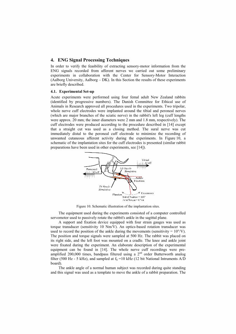
4.1. Experimental Set-up Acute experiments were performed using four femal adult New Zealand rabbits (identified by progressive numbers). The Danish Committee for Ethical use of Animals in Research approved all procedures used in the experiments. Two tripolar, whole nerve cuff electrodes were implanted around the tibial and peroneal nerves (which are major branches of the sciatic nerve) in the rabbit's left leg (cuff lengths were approx. 20 mm; the inner diameters were 2 mm and 1.8 mm, respectively). The cuff electrodes were produced according to the procedure described in [14] except that a straight cut was used as a closing method. The sural nerve was cut immediately distal to the peroneal cuff electrode to minimize the recording of unwanted cutaneous afferent activity during the experiments. In Figure 10, a schematic of the implantation sites for the cuff electrodes is presented (similar rabbit preparations have been used in other experiments, see [14]).
Figure 10. Schematic illustration of the implantation sites.
The equipment used during the experiments consisted of a computer controlled servomotor used to passively rotate the rabbit's ankle in the sagittal plane.
A support and fixation device equipped with four strain gauges was used as torque transducer (sensitivity 10 Nm/V). An optics-based rotation transducer was used to record the position of the ankle during the movements (sensitivity = 10°/V). The position and torque signals were sampled at 500 Hz. The rabbit was placed on its right side, and the left foot was mounted on a cradle. The knee and ankle joint were fixated during the experiment. An elaborate description of the experimental equipment can be found in [14]. The whole nerve cuff recordings were pre-amplified 200,000 times, bandpass filtered using a 2nd order Butterworth analog filter (500 Hz - 5 kHz), and sampled at fS =10 kHz (12 bit National Intruments A/D board).
The ankle angle of a normal human subject was recorded during quite standing and this signal was used as a template to move the ankle of a rabbit preparation. The

whole nerve activity of the tibial and peroneal nerves were recorded as described in [14]. All ENG recordings were rectified and bin integrated during a 9 ms window. The position and torque data were low-pass filtered at fSP = 100 Hz (12th order digital Butterworth filter).
4.2. Fuzzy Models Three fuzzy models were implemented with characteristics as follows:
1. The Modified FCRM Fuzzy Model is a Takagi-Sugeno (TS) fuzzy system. To obtain the rules directly from the data, a fuzzy clustering algorithm named fuzzy C-regression model (FCRM) is implemented [15].
2. The Adaptive Network-based Fuzzy Inference System (ANFIS) model is a TS fuzzy system implemented as a feed-forward neural network. The principal characteristic of this network is the hybrid learning procedure described in [16].
3. The Dynamic Non-Singleton Fuzzy Logic System (DNSFLS) is a Mamdani fuzzy system, implemented in the framework of recurrent neural networks [17].
4.3. Results of the prediction To compare the performances of the different fuzzy models, the root mean square (RMS) of the prediction error has been introduced as a figure of merit. In Tables 1 the RMS of the prediction error is presented.
Table 1: RMS of the Prediction Error for the Different Fuzzy Models
Fuzzy model Training Traject RMS
Test Traject RMS
Rule Number
FCRM 0.0216 0.0480 49 ANFIS 0.0047 0.0079 49 DNSFLS 0.0013 0.0057 45
5. Conclusions This paper show research activities carried out at Scuola Superiore Sant’Anna for the development of a cybernetic prosthesis. We are currently designing of a new prototype of the biomechatronic hand and developing ENG signal processing techniques to characterize the afferent response of the PNS. Moreover, the Consortium of the GRIP EU Project (coordinated by Scuola Superiore Sant’Anna) is currently developing an implantable system to record and stimulate the PNS with a telemetry connection with an external control system. This device can be used in experiments to design the cybernetic prosthesis.
6. Acknowledgements This work has been supported by a research project entitled “Design and development of innovative components for sensorized prosthetic systems” currently ongoing at the “Applied Research Center on Rehabilitation Engineering” funded by INAIL (National Institute for Insurance of Injured Workers), and originated by a joint initiative promoted by INAIL and by Scuola Superiore Sant’Anna. This work has been partly funded by the GRIP EU Project (“An integrated system for the neuroelectric control of grasp in disabled persons”, ESPRIT LTR #26322).
The authors are also grateful to Mr. Carlo Filippeschi and Mr. Gabriele Favati for their valuable technical assistance. The authors would also thank Mr. Rinaldo

Sacchetti for helpful discussions and criticism on the biomechatronic prosthetic hand concept.
References [1] D. C. Simpson, The Choice of Control System for multimovement prostheses:
Extended Physiological Proprioception (EPP), in The Control of Upper-Extremity Prostheses and Orthoses, P. Herberts et al., Eds., 1974.
[2] J. A. Doeringer, N. Hogan, Performance of above elbow body-powered prostheses in visually guided unconstrained motion task, IEEE Trans. Rehab. Eng. 42 (1995), 621-631.
[3] P.J. Agnew, Functional effectiveness of a myoelectric prosthesis compared with a functional split hook prosthesis: a single subject experiment, Prost. & Orth. Int. 5 (1981), 92–96.
[4] S.-E. Baek, S.-H. Lee, J.-H. Chang, Design and control of a robotic finger for prosthetic hands, Proc. Int. Conf .Intelligent Robots and Systems (1999), 113-117.
[5] M. E. Cupo, S. J. Sheredos, Clinical Evaluation of a new, above elbow, body powered prosthetic arm: a final report, J. Rehab. Res. Dev. 35 (1998), 431-446.
[6] R. Doshi, C. Yeh, M. LeBlanc, The design and development of a gloveless endoskeletal prosthetic hand, J. Rehab. Res. Dev. 35 (1998), 388–395.
[7] P. J. Kyberd, O. E. Holland, P. H. Chappel, S. Smith, R. Tregidgo, P. J. Bagwell, and M. Snaith, MARCUS: a two degree of freedom hand prosthesis with hierarchical grip control, IEEE Trans. Rehab. Eng. 3 (1995), 70–6.
[8] D. H. Silcox, M. D. Rooks, R. R. Vogel, L. L. Fleming, Myoelectric Prostheses, J. Bone & Joint Surg., 75 (1993), 1781–1789.
[9] R. Vinet, Y. Lozac’h, N. Beaundry, G. Drouin, Design methodology for a multifunctional hand prosthesis, J. Rehab. Res. Dev. 32 (1995), 316–324.
[10] M. R. Cutkosky, Robotic Grasping and Fine Manipulation, Boston: Kluwer Academic Publishers, 1985.
[11] Carrozza M.C., Dario P., Lazzarini R., et al, An actuator system for a novel biomechatronic prosthetic hand. In Proceedings of Actuator 2000 Bremen, Germany (2000), 276-280.
[12] K. Nagai, Y. Eto, D. Asai, M. Yazaki, Development of a three-fingered robotic hand-wrist for compliant motion, Proc. Int. Conf. Intelligent Robots and Systems (1998), 476-481.
[13] D.T.V. Pawlock, R.D.Howe, Dynamic contact of the human fingerpad against a flat surface, ASME J Biomech Eng 121 (1999), 605-611.
[14] R.R. Riso and Farhad K. Mosallaie and Winnie Jensen and Thomas Sinkjaer, Nerve Cuff recordings of muscle afferent activity from tibial and peroneal nerves in rabbit during passive ankle motion, IEEE Trans Rehab Eng, 2000.
[15] E. Kim, M.Park, S.Ji, and M.Park, “A new approach to fuzzy modeling”, IEEE Trans Fuzzy Sys, vol. 5, pp. 328-337, August 1997.
[16] J.-S. R. Jang, “ANFIS: Adaptive-network-based fuzzy inference system”, IEEE Trans Sys Man Cyber, vol. 23, pp. 665-685, May/June 1993.
[17] G.C. Mouzouris, J.M. Mendel, “Dynamic non-singleton fuzzy logic systems for nonlinear modeling”, IEEE Trans Fuzzy Sys, vol. 5, pp.199-208, May 1997.