Design and Characterization of Novel Wear Resistant Multilayer CVD Coatings with Improved Adhesion...
6
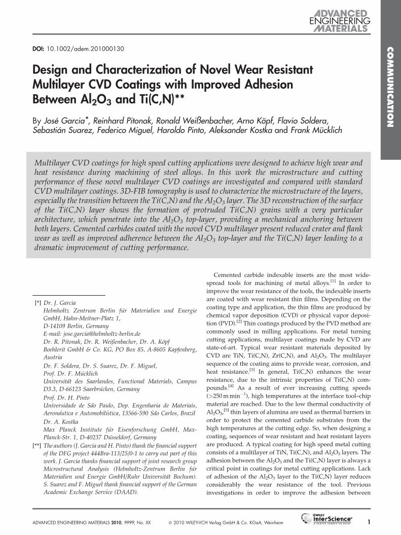
DOI: 10.1002/adem.201000130 Design and Characterization of Novel Wear Resistant Multilayer CVD Coatings with Improved Adhesion Between Al 2 O 3 and Ti(C,N)** By Jose ´ Garcia * , Reinhard Pitonak, Ronald Weißenbacher, Arno Ko ¨pf, Flavio Soldera, Sebastia ´n Suarez, Federico Miguel, Haroldo Pinto, Aleksander Kostka and Frank Mu ¨cklich Cemented carbide indexable inserts are the most wide- spread tools for machining of metal alloys. [1] In order to improve the wear resistance of the tools, the indexable inserts are coated with wear resistant thin films. Depending on the coating type and application, the thin films are produced by chemical vapor deposition (CVD) or physical vapor deposi- tion (PVD). [2] Thin coatings produced by the PVD method are commonly used in milling applications. For metal turning cutting applications, multilayer coatings made by CVD are state-of-art. Typical wear resistant materials deposited by CVD are TiN, Ti(C,N), Zr(C,N), and Al 2 O 3 . The multilayer sequence of the coating aims to provide wear, corrosion, and heat resistance. [3] In general, Ti(C,N) enhances the wear resistance, due to the intrinsic properties of Ti(C,N) com- pounds. [4] As a result of ever increasing cutting speeds (>250 m min 1 ), high temperatures at the interface tool–chip material are reached. Due to the low thermal conductivity of Al 2 O 3 , [5] thin layers of alumina are used as thermal barriers in order to protect the cemented carbide substrates from the high temperatures at the cutting edge. So, when designing a coating, sequences of wear resistant and heat resistant layers are produced. A typical coating for high speed metal cutting consists of a multilayer of TiN, Ti(C,N), and Al 2 O 3 layers. The adhesion between the Al 2 O 3 and the Ti(C,N) layer is always a critical point in coatings for metal cutting applications. Lack of adhesion of the Al 2 O 3 layer to the Ti(C,N) layer reduces considerably the wear resistance of the tool. Previous investigations in order to improve the adhesion between COMMUNICATION [*] Dr. J. Garcia Helmholtz Zentrum Berlin fu ¨r Materialien und Energie GmbH, Hahn-Meitner-Platz 1, D-14109 Berlin, Germany E-mail: [email protected] Dr. R. Pitonak, Dr. R. Weißenbacher, Dr. A. Ko¨pf Boehlerit GmbH & Co. KG, PO Box 85, A-8605 Kapfenberg, Austria Dr. F. Soldera, Dr. S. Suarez, Dr. F. Miguel, Prof. Dr. F. Mu ¨cklich Universita¨t des Saarlandes, Functional Materials, Campus D3.3, D-66123 Saarbru ¨cken, Germany Prof. Dr. H. Pinto Universidade de Sa˜o Paulo, Dep. Engenharia de Materiais, Aerona´utica e Automobilı´stica, 13566-590 Sa˜o Carlos, Brazil Dr. A. Kostka Max Planck Institute fu ¨r Eisenforschung GmbH, Max- Planck-Str. 1, D-40237 Du ¨sseldorf, Germany [**] The authors (J. Garcia and H. Pinto) thank the financial support of the DFG project 444Bra-113/25/0-1 to carry out part of this work. J. Garcia thanks financial support of joint research group Microstructural Analysis (Helmholtz-Zentrum Berlin fu ¨r Materialien und Energie GmbH/Ruhr Universita¨t Bochum). S. Suarez and F. Miguel thank financial support of the German Academic Exchange Service (DAAD). Multilayer CVD coatings for high speed cutting applications were designed to achieve high wear and heat resistance during machining of steel alloys. In this work the microstructure and cutting performance of these novel multilayer CVD coatings are investigated and compared with standard CVD multilayer coatings. 3D-FIB tomography is used to characterize the microstructure of the layers, especially the transition between the Ti(C,N) and the Al 2 O 3 layer. The 3D reconstruction of the surface of the Ti(C,N) layer shows the formation of protruded Ti(C,N) grains with a very particular architecture, which penetrate into the Al 2 O 3 top-layer, providing a mechanical anchoring between both layers. Cemented carbides coated with the novel CVD multilayer present reduced crater and flank wear as well as improved adherence between the Al 2 O 3 top-layer and the Ti(C,N) layer leading to a dramatic improvement of cutting performance. ADVANCED ENGINEERING MATERIALS 2010, 9999, No. XX ß 2010 WILEY-VCH Verlag GmbH & Co. KGaA, Weinheim 1
-
Upload
independent -
Category
Documents
-
view
0 -
download
0
Transcript of Design and Characterization of Novel Wear Resistant Multilayer CVD Coatings with Improved Adhesion...
CO
DOI: 10.1002/adem.201000130MM
UN
ICAT
Design and Characterization of Novel Wear ResistantMultilayer CVD Coatings with Improved AdhesionBetween Al2O3 and Ti(C,N)**
ION
By Jose Garcia*, Reinhard Pitonak, Ronald Weißenbacher, Arno Kopf, Flavio Soldera,Sebastian Suarez, Federico Miguel, Haroldo Pinto, Aleksander Kostka and Frank Mucklich
Multilayer CVD coatings for high speed cutting applications were designed to achieve high wear andheat resistance during machining of steel alloys. In this work the microstructure and cuttingperformance of these novel multilayer CVD coatings are investigated and compared with standardCVD multilayer coatings. 3D-FIB tomography is used to characterize the microstructure of the layers,especially the transition between the Ti(C,N) and the Al2O3 layer. The 3D reconstruction of the surfaceof the Ti(C,N) layer shows the formation of protruded Ti(C,N) grains with a very particulararchitecture, which penetrate into the Al2O3 top-layer, providing a mechanical anchoring betweenboth layers. Cemented carbides coated with the novel CVD multilayer present reduced crater and flankwear as well as improved adherence between the Al2O3 top-layer and the Ti(C,N) layer leading to adramatic improvement of cutting performance.
[*] Dr. J. GarciaHelmholtz Zentrum Berlin fur Materialien und EnergieGmbH, Hahn-Meitner-Platz 1,D-14109 Berlin, GermanyE-mail: [email protected]
Dr. R. Pitonak, Dr. R. Weißenbacher, Dr. A. KopfBoehlerit GmbH & Co. KG, PO Box 85, A-8605 Kapfenberg,Austria
Dr. F. Soldera, Dr. S. Suarez, Dr. F. Miguel,Prof. Dr. F. MucklichUniversitat des Saarlandes, Functional Materials, CampusD3.3, D-66123 Saarbrucken, Germany
Prof. Dr. H. PintoUniversidade de Sao Paulo, Dep. Engenharia de Materiais,Aeronautica e Automobilıstica, 13566-590 Sao Carlos, Brazil
Dr. A. KostkaMax Planck Institute fur Eisenforschung GmbH, Max-Planck-Str. 1, D-40237 Dusseldorf, Germany
[**] The authors (J. Garcia and H. Pinto) thank the financial supportof the DFG project 444Bra-113/25/0-1 to carry out part of thiswork. J. Garcia thanks financial support of joint research groupMicrostructural Analysis (Helmholtz-Zentrum Berlin furMaterialien und Energie GmbH/Ruhr Universitat Bochum).S. Suarez and F. Miguel thank financial support of the GermanAcademic Exchange Service (DAAD).
ADVANCED ENGINEERING MATERIALS 2010, 9999, No. XX � 2010 WILEY-VCH Verlag GmbH & Co. KGaA, Weinheim 1
Cemented carbide indexable inserts are the most wide-
spread tools for machining of metal alloys.[1] In order to
improve the wear resistance of the tools, the indexable inserts
are coated with wear resistant thin films. Depending on the
coating type and application, the thin films are produced by
chemical vapor deposition (CVD) or physical vapor deposi-
tion (PVD).[2] Thin coatings produced by the PVD method are
commonly used in milling applications. For metal turning
cutting applications, multilayer coatings made by CVD are
state-of-art. Typical wear resistant materials deposited by
CVD are TiN, Ti(C,N), Zr(C,N), and Al2O3. The multilayer
sequence of the coating aims to provide wear, corrosion, and
heat resistance.[3] In general, Ti(C,N) enhances the wear
resistance, due to the intrinsic properties of Ti(C,N) com-
pounds.[4] As a result of ever increasing cutting speeds
(>250 m min�1), high temperatures at the interface tool–chip
material are reached. Due to the low thermal conductivity of
Al2O3,[5] thin layers of alumina are used as thermal barriers in
order to protect the cemented carbide substrates from the
high temperatures at the cutting edge. So, when designing a
coating, sequences of wear resistant and heat resistant layers
are produced. A typical coating for high speed metal cutting
consists of a multilayer of TiN, Ti(C,N), and Al2O3 layers. The
adhesion between the Al2O3 and the Ti(C,N) layer is always a
critical point in coatings for metal cutting applications. Lack
of adhesion of the Al2O3 layer to the Ti(C,N) layer reduces
considerably the wear resistance of the tool. Previous
investigations in order to improve the adhesion between
CO
MM
UN
ICATIO
N
J. Garcia et al./Design and Characterization of Novel Wear Resistant Multilayer . . .
the Ti(C,N) and the Al2O3 coating propose the use of an
intermediate layer made of Ti(C,N,O).[6]
In a recent development novel Ti(C,N) coatings with a
gradient in grain morphology and composition were pro-
duced by modifying the deposition conditions during CVD.[7]
The wear resistance is provided by a modified microstructure
of the Ti(C,N) phase.[8] In ref. [8] the microstructure of the
novel Ti(C,N) layer produced after[9] was investigated. It was
found that this novel Ti(C,N) layer is a nitrogen-rich layer with
an overall C/N ratio of 0.16:0.84. The Ti(C,N) phase presents a
composite structure, showing the presence of two Ti(C,N)
crystallites co-existing in the layer (star-shape and lenticular-
like). These crystallites protrude from the surface of the
Ti(C,N) layer, giving a topographic rough-effect to the coating
layer. These protruded crystallites may improve the adhesion
of subsequent coating layers, such as Al2O3 layers, to
the Ti(C,N) layer, due to mechanical anchoring. Within the
method described in ref. [9] a tailored transition from the
Ti(C,N) into the k-Al2O3 without the production of inter-
mediate layers is obtained.
In this work, the microstructure and cutting performance
of a novel multilayer system containing, among others, a
graded Ti(C,N) layer with protruded crystallites is investi-
gated; in particular, the spatial architecture of the interface
between the Ti(C,N) and the k-Al2O3 layer by 3D-FIB
tomography. High speed cutting tests of cemented carbides
coated with the novel multilayer system are carried out under
severe conditions and compared with cemented carbides
coated with conventional multilayer coatings produced by
state-of-art methods.
Experimental
Multilayer coatings were prepared in an industrial hot wall
CVD reactor at temperatures between 900 and 1050 8C and
pressures between 70 and 150 mbar. The novel multilayer
coating consists of five thin layers: TiN, two Ti(C,N) layers
(produced by medium temperature (MT), and high tempera-
ture (HT) CVD), k-Al2O3 and a thin TiN top-layer. In
particular, the production of the MT–Ti(C,N) and the
HT–Ti(C,N) layer was carried out following these chemical
reactions:
MT–Ti(C,N):
TiCl4ðgÞ þ CH3CNðgÞ þ 21=2H2ðgÞ ¼> TiðCx;NyÞðsÞþ CH4ðgÞ þ 4HClðgÞ
(1)
where (s) means solid phase and (g) gas phase.
The reaction takes place at a temperature range between
750 and 950 8C; for this reason the process is called
‘‘moderate’’ or ‘‘medium’’ CVD process and in the following
it will be referred as MT–CVD.
HT–Ti(C,N):
TiCl4ðgÞ þ xCH4ðgÞ þ1
2ð1� xÞN2ðgÞ
þ 2ð1� xÞH2ðgÞ ¼> TiCxN1�xðsÞ þ 4HClðgÞ(2)
2 http://www.aem-journal.com � 2010 WILEY-VCH Verlag GmbH & Co. K
The reaction takes place at temperatures between 950 and
1050 8C and this process is called CVD or ‘‘high’’ temperature
CVD, and in the following it will be referred as HT–CVD. In
this study all HT–CVD Ti(C,N) layers were produced
following the modified CVD method described in ref. [7].
The mutilayer coating was analyzed by light microscopy
on polished cross-section of samples. SEM analyses were
performed in a Jeol JSM 6500F equipped with an EDX. The
results of TEM were carried out using a Jeol 2200 FS operating
at 200 kV. TEM specimens were prepared using focused ion
beam (FIB) system Jeol JEM-9320 operating at 30 kV. FIB
tomography was performed in a dual beam system (FIB
combined with SEM, FEI Strata 235 DB). The series of images
for tomography were acquired with the software Slice& View
(FEI). The processing and 3D reconstruction of the serial
sectioning images was done with A4i and AMIRA software,
while for the quantitative analysis MAVI was employed. A Pt
layer was deposited on top of the region of interest (ROI) in
order to protect the material, improve the quality of the
FIB-cuts and provide a sharp interface between the sample
surface and the Pt layer, which would be later used for slice
alignment. The Pt layer was deposited by ion beam induced
deposition (IBID) in situ in the Dual Beam System SEM/FIB.
Cutting tests were carried out in continuous turning of
42CrMo4 steel under high speed cutting conditions (cutting
speed¼ 280 m min�1, depth of cut¼ 1.5 mm, feed¼ 0.28 mm
U�1, and continuous cooling). The response to flank wear and
crater wear was measured before plastic deformation takes
place. Worn interfaces were analyzed on cross-sections of
indexable inserts after complete damage of the tools.
Microstructure of Coating Multilayer Systems
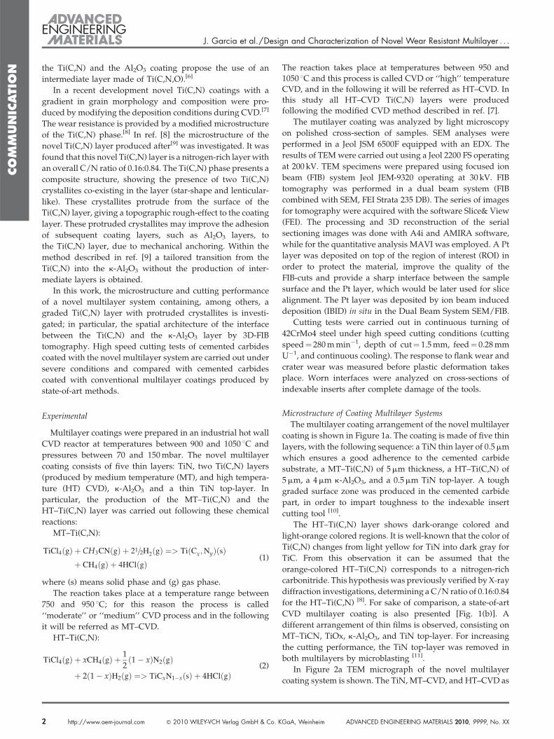
The multilayer coating arrangement of the novel multilayer
coating is shown in Figure 1a. The coating is made of five thin
layers, with the following sequence: a TiN thin layer of 0.5 mm
which ensures a good adherence to the cemented carbide
substrate, a MT–Ti(C,N) of 5 mm thickness, a HT–Ti(C,N) of
5 mm, a 4 mm k-Al2O3, and a 0.5 mm TiN top-layer. A tough
graded surface zone was produced in the cemented carbide
part, in order to impart toughness to the indexable insert
cutting tool [10].
The HT–Ti(C,N) layer shows dark-orange colored and
light-orange colored regions. It is well-known that the color of
Ti(C,N) changes from light yellow for TiN into dark gray for
TiC. From this observation it can be assumed that the
orange-colored HT–Ti(C,N) corresponds to a nitrogen-rich
carbonitride. This hypothesis was previously verified by X-ray
diffraction investigations, determining a C/N ratio of 0.16:0.84
for the HT–Ti(C,N) [8]. For sake of comparison, a state-of-art
CVD multilayer coating is also presented [Fig. 1(b)]. A
different arrangement of thin films is observed, consisting on
MT–TiCN, TiOx, k-Al2O3, and TiN top-layer. For increasing
the cutting performance, the TiN top-layer was removed in
both multilayers by microblasting [11].
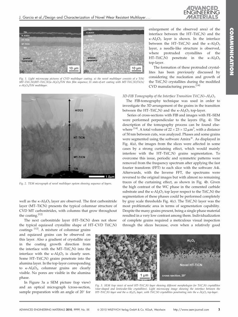
In Figure 2a TEM micrograph of the novel multilayer
coating system is shown. The TiN, MT–CVD, and HT–CVD as
GaA, Weinheim ADVANCED ENGINEERING MATERIALS 2010, 9999, No. XX
CO
MM
UN
ICATIO
N
J. Garcia et al./Design and Characterization of Novel Wear Resistant Multilayer . . .
Fig. 1. Light microscopy pictures of CVD multilayer coating. a) the novel multilayer consists of a TiN/MT–Ti(C,N)/HT–Ti(C,N)/k-Al2O3/TiN thin film sequence; b) state-of-art coating with MT-Ti(C,N)/TiOx/k-Al2O3/TiN multilayer.
Fig. 2. TEM micrograph of novel multilayer system showing sequence of layers.
well as the k-Al2O3 layer are observed. The first carbonitride
layer (MT–TiCN) presents the typical columnar structure of
CVD MT carbonitrides, with columns that grow throughout
the coating.[12]
The next carbonitride layer (HT–TiCN) does not show
the typical equiaxed crystallite shape of HT–CVD Ti(C,N)
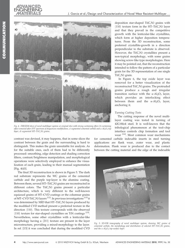
Fig. 3. SEM (top view) of novel HT–Ti(C,N) layer showing different morphologies for Ti(C,N) crystallites(star-shaped and lenticular-like crystallites). Light microscopy image showing the interface between theHT–Ti(C,N) layer and the k-Al2O3 layer, with Ti(C,N) crystallites penetrating into the k-Al2O3 top-layer.
coatings [12]. A mixture of columnar grains
and equiaxed grains can be observed on
this layer. Also a gradient of crystallite size
in the coating growth direction from
the interface with the MT–Ti(C,N) into the
interface with the k-Al2O3 is clearly seen.
Some HT–Ti(C,N) grains penetrate into the
alumina layer. In the top-layer corresponding
to k-Al2O3, columnar grains are clearly
visible. No pores are visible in the alumina
phase.
In Figure 3a a SEM picture (top view)
and an optical micrograph (cross-section,
sample preparation with an angle of 208 for
ADVANCED ENGINEERING MATERIALS 2010, 9999, No. XX � 2010 WILEY-VCH Verlag GmbH & Co. KG
enlargement of the observed area) of the
interface between the HT–Ti(C,N) and the
k-Al2O3 layer is shown. In the interface
between the HT–Ti(C,N) and the k-Al2O3
layer, a needle-like structure is observed,
where protruded crystallites of the
HT–Ti(C,N) penetrate in the k-Al2O3
top-layer.
The formation of these protruded crystal-
lites has been previously discussed by
considering the nucleation and growth of
the Ti(C,N) crystallites during the modified
CVD manufacturing process.[14]
3D-FIB Tomography of the Interface Transition Ti(C,N)–Al2O3
The FIB-tomography technique was used in order to
investigate the 3D arrangement of the grains in the transition
between the HT–Ti(C,N) and the k-Al2O3 top-layer.
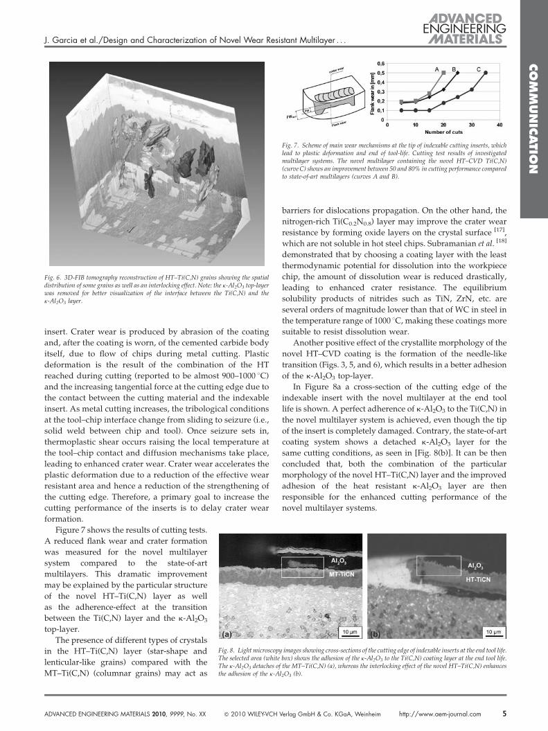
Series of cross-sections with FIB and images with FE–SEM
were performed perpendicular to the layers (Fig. 4). The
description of the tomography process can be found else-
where [14]. A total volume of 22� 23� 12 mm3, with a distance
of 50 nm between cuts, was analyzed. Phases and some grains
were segmented using the software Amira1. As displayed in
Fig. 4(a), the images from the slices were affected in some
cases by a strong curtaining effect, which would mainly
interfere with the HT–Ti(C,N) grains segmentation. To
overcome this issue, periodic and symmetric patterns were
removed from the frequency spectrum after applying the fast
fourier transform (FFT) to each slice with the software A4i.
Afterwards, with the Inverse FFT, the spectrums were
reversed to the original images but with almost no remaining
traces of the curtaining effect, as shown in Fig. 4b. Given
the high contrast of the WC phase in the cemented carbide
substrate and the k-Al2O3 top layer respect to the Ti(C,N) the
segmentation of these phases could be performed completely
by gray scale thresholds Fig. 4(c). The Ti(C,N) layer was the
most problematic area in terms of segmentation capability.
Despite the many grains present, being a single phase material
resulted in a very low contrast among them. Individualization
of complete grains required a meticulous visual inspection
through the slices because, even when a relatively good
aA, Weinheim http://www.aem-journal.com 3
CO
MM
UN
ICATIO
N
J. Garcia et al./Design and Characterization of Novel Wear Resistant Multilayer . . .
Fig. 4. FIB/SEM slices of novel multilayer system: a) original slice with strong curtaining effect, b) curtainingeffect removed after FFT spectrum of frequencies modification, c) segmented cemented carbide and k-Al2O3 toplayer, d) segmented HT–Ti(C,N) grains.
Fig. 5. 3D-FIB tomography of novel multilayer system, showing WC grains ofcemented carbide, the morphology and distribution of selected HT–Ti(C,N) grains,and the k-Al2O3 top-surface layer.
contrast was devised, it may happens, that in some slices the
contrast between the grain and the surrounding is hard to
distinguish. This makes the grain unsuitable for analysis. As
for the suitable ones, each of them had to be differently
processed: smoothing, edge detection and shading correction
filters, contrast/brightness manipulation, and morphological
operations were selectively employed to enhance the visua-
lization of each grain, leading to their manual segmentation
[Fig. 4(d)].
The final 3D reconstruction is shown in Figure 5. The dark
red substrate represents the WC grains of the cemented
carbide and the purple top-layer is the alumina coating.
Between them, several HT–Ti(C,N) grains are reconstructed in
different colors. The Ti(C,N) grains present a particular
architecture, which is very different to the well-known
equiaxed grains of HT–CVD coatings or the columnar grains
of MT–CVD Ti(C,N) layers [12]. In previous investigations [13] it
was determined by XRD that HT–Ti(C,N) layers produced by
the modified CVD method present a preferred texture in the
direction h110i. This texture corresponds with the observed
h110i texture for star-shaped crystallites on TiN coatings [15].
Nevertheless, some other crystallites with a lenticular-like
morphology having a h211i texture are present in the layer
microstructure, providing a mixed-morphology to the layer.
In ref. [13] it was concluded that during the modified CVD
4 http://www.aem-journal.com � 2010 WILEY-VCH Verlag GmbH & Co. KGaA, Weinheim
deposition star-shaped Ti(C,N) grains with
h110i texture form in the HT–Ti(C,N) layer
and that they prevail in the competitive
growth with the lenticular-like crystallites,
which form at higher deposition tempera-
tures. From the 3D reconstruction, some
preferred crystallite-growth in a direction
perpendicular to the substrate is observed.
However, the Ti(C,N) crystallites present a
non-typical morphology, with some grains
showing screw-like type morphologies. Here
it may be pointed out, that the reconstruction
intended to follow the pattern of a particular
grain for the 3D representation of one single
Ti(C,N) grain.
In Figure 6, the top oxide layer was
removed for a better visualization of the
reconstructed Ti(C,N) grains. The protruded
grains produce a rough and irregular
transition surface with the k-Al2O3 layer,
which provides an interlocking effect
between them and the k-Al2O3 layer,
anchoring it.
Turning Cutting Tests
The cutting response of the novel multi-
layer coating was tested in turning of
42CrMo4 steel. It is well-known that the
tribological phenomenon at the tool–chip
interface controls chip formation and tool
wear [16]. Most common wear mechanisms
for cemented carbide indexable inserts in steel turning
applications are flank wear, crater wear, and plastic
deformation. Flank wear is produced due to the contact
between the cutting material and the edge of the indexable
ADVANCED ENGINEERING MATERIALS 2010, 9999, No. XX
CO
MM
UN
ICATIO
N
J. Garcia et al./Design and Characterization of Novel Wear Resistant Multilayer . . .
Fig. 6. 3D-FIB tomography reconstruction of HT–Ti(C,N) grains showing the spatialdistribution of some grains as well as an interlocking effect. Note: the k-Al2O3 top-layerwas removed for better visualization of the interface between the Ti(C,N) and thek-Al2O3 layer.
Fig. 7. Scheme of main wear mechanisms at the tip of indexable cutting inserts, whichlead to plastic deformation and end of tool-life. Cutting test results of investigatedmultilayer systems. The novel multilayer containing the novel HT–CVD Ti(C,N)(curve C) shows an improvement between 50 and 80% in cutting performance comparedto state-of-art multilayers (curves A and B).
insert. Crater wear is produced by abrasion of the coating
and, after the coating is worn, of the cemented carbide body
itself, due to flow of chips during metal cutting. Plastic
deformation is the result of the combination of the HT
reached during cutting (reported to be almost 900–1000 8C)
and the increasing tangential force at the cutting edge due to
the contact between the cutting material and the indexable
insert. As metal cutting increases, the tribological conditions
at the tool–chip interface change from sliding to seizure (i.e.,
solid weld between chip and tool). Once seizure sets in,
thermoplastic shear occurs raising the local temperature at
the tool–chip contact and diffusion mechanisms take place,
leading to enhanced crater wear. Crater wear accelerates the
plastic deformation due to a reduction of the effective wear
resistant area and hence a reduction of the strengthening of
the cutting edge. Therefore, a primary goal to increase the
cutting performance of the inserts is to delay crater wear
formation.
Fig. 8. Light microscopy images showing cross-sections of the cutting edge of indexable inserts at the end tool life.The selected area (white box) shows the adhesion of the k-Al2O3 to the Ti(C,N) coating layer at the end tool life.The k-Al2O3 detaches of the MT–Ti(C,N) (a), whereas the interlocking effect of the novel HT–Ti(C,N) enhancesthe adhesion of the k-Al2O3 (b).
Figure 7 shows the results of cutting tests.
A reduced flank wear and crater formation
was measured for the novel multilayer
system compared to the state-of-art
multilayers. This dramatic improvement
may be explained by the particular structure
of the novel HT–Ti(C,N) layer as well
as the adherence-effect at the transition
between the Ti(C,N) layer and the k-Al2O3
top-layer.
The presence of different types of crystals
in the HT–Ti(C,N) layer (star-shape and
lenticular-like grains) compared with the
MT–Ti(C,N) (columnar grains) may act as
ADVANCED ENGINEERING MATERIALS 2010, 9999, No. XX � 2010 WILEY-VCH
barriers for dislocations propagation. On the other hand, the
nitrogen-rich Ti(C0.2N0.8) layer may improve the crater wear
resistance by forming oxide layers on the crystal surface [17],
which are not soluble in hot steel chips. Subramanian et al. [18]
demonstrated that by choosing a coating layer with the least
thermodynamic potential for dissolution into the workpiece
chip, the amount of dissolution wear is reduced drastically,
leading to enhanced crater resistance. The equilibrium
solubility products of nitrides such as TiN, ZrN, etc. are
several orders of magnitude lower than that of WC in steel in
the temperature range of 1000 8C, making these coatings more
suitable to resist dissolution wear.
Another positive effect of the crystallite morphology of the
novel HT–CVD coating is the formation of the needle-like
transition (Figs. 3, 5, and 6), which results in a better adhesion
of the k-Al2O3 top-layer.
In Figure 8a a cross-section of the cutting edge of the
indexable insert with the novel multilayer at the end tool
life is shown. A perfect adherence of k-Al2O3 to the Ti(C,N) in
the novel multilayer system is achieved, even though the tip
of the insert is completely damaged. Contrary, the state-of-art
coating system shows a detached k-Al2O3 layer for the
same cutting conditions, as seen in [Fig. 8(b)]. It can be then
concluded that, both the combination of the particular
morphology of the novel HT–Ti(C,N) layer and the improved
adhesion of the heat resistant k-Al2O3 layer are then
responsible for the enhanced cutting performance of the
novel multilayer systems.
Verlag GmbH & Co. KGaA, Weinheim http://www.aem-journal.com 5
CO
MM
UN
ICATIO
N
J. Garcia et al./Desig . .
Conclusions
In this work a novel multilayer coating system was
characterized regarding its microstructure and cutting
performance in turning of steel. The microstructure at the
interface between the Ti(C,N) and the k-Al2O3 layer was
investigated by 3D-FIB tomography. The cutting response of
the multilayer was compared with a conventional state-of-art
multilayer system. Conclusions can be summarized as
follows:
� T
6
he 3D reconstruction shows Ti(C,N) with a very particular
architecture, different from conventional equiaxed or
columnar grains of CVD Ti(C,N) coatings. From the
3D-reconstruction, some grains showing screw-like type
morphologies with a preferred growth perpendicular to
the substrate are observed.
� R
esults of 3D-FIB tomography confirms that Ti(C,N) crys-tallites at the interface between the HT–Ti(C,N) and the
k-Al2O3 layer present a needle-like structure. The Ti(C,N)
protruded crystallites penetrate into the k-Al2O3 top-layer,
providing mechanical anchoring between the layers.
� In
vestigations on cross-sections of worn indexable insertsshow improved adherence between the k-Al2O3 top-layer
and the Ti(C,N) layer – due to the needle-like transition –
compared with conventional Ti(C,N)-k-Al2O3 systems.
� C
emented carbides coated with the novel CVD multilayerpresent reduced crater and flank wear compared to state-
of-art indexable inserts, leading to enhanced cutting
performances. Reasons for the dramatic improvement of
the performance (up to 80%) are the improved wear resist-
ance of the novel HT–Ti(C,N) layer and the better adhesion
of the k-Al2O3 heat-resistant layer, both retarding crater
wear and plastic deformation.
Received: March 30, 2010
Final Version: May 20, 2010
Published online: XX XX XX
http://www.aem-journal.com � 2010 WILEY-VCH Verlag GmbH & Co. K
n and Characterization of Novel Wear Resistant Multilayer .
[1] K. J. A. Brookes, World Directory and Handbook of Hard-
metals and Hard Materials, 5th Edn, East Bamet, UK
International Carbide Data, 1992.
[2] H. O. Pierson, Handbook of Chemical Vapour Deposition,
Noyes Publication/William Andrew Publishing LLC,
Norwich, New York, USA 1999.
[3] S. Ruppi, M. Halvarsson, Thin Solid Films 1999, 353,
182.
[4] W. Lengauer, in: Handbook of Ceramic Hard Materials,
Vol. 1 (Ed: R. Riedel), Wiley-VCH, 2000 p. 202–252.
[5] D. G. Gahill, S. M. Lee, T. I. Selander, J. Appl. Phys. 1998,
83(11), 5783.
[6] H. Halvarsson, S. Vuorinen, Surf. Coat. Technol. 1993,
56, 165.
[7] R. Pitonak, J. Garcia, R. Weissenbacher, K. Udier, Aus-
trian Patent AT503050 B1 2007.
[8] R. Pitonak, J. Garcia, A. Koepf, R. Weissenbacher, Proc.
15. IFHTSE and SMT 20, 2006, Vol. SE-CVD, CD-Version,
Austria
[9] R. Pitonak, J. Garcia, R. Weissenbacher, K. Udier, US
Patent US2009226758 A1 2009.
[10] C. Barbatti, J. Garcia, F. Sket, A. Kostka, A. Pyzalla, Int. J.
Surf. Coat. Technol. 2008, 202, 5962.
[11] C. Barbatti, J. Garcia, H. Pinto, A. Kostka, A. Di Prinzio,
M. Staia, R. Pitonak, A. Pyzalla, Int. J. Surf. Coat. Technol.
2009, 203, 3708.
[12] A. Larsson, S. Ruppi, Thin Solid Films 2002, 402, 203.
[13] R. Pitonak, J. Garcia, R. Weissenbacher, A. Koepf, sub-
mitted to Int. J. Surf. Coat. Technol. 2010.
[14] A. Velichko, F. Mucklich, Adv. Solid State Phys. 2009, 480, 331.
[15] H.-E. Cheng, M.-H. Hon, J. Appl. Phys. 1996, 79(10), 8047.
[16] H. O. Gedonke, S. V. Subramanian, Surf. Coat. Technol.
2002, 149, 151.
[17] H.-Y. Chen, F.-H. Lu, J. Vac. Sci. Technol. A 2005, 23(4),
1006.
[18] S. V. Subramanian, S. S. Ingle, D. A. R. Kay, Surf. Coat.
Technol. 1993, 61, 293.
GaA, Weinheim ADVANCED ENGINEERING MATERIALS 2010, 9999, No. XX