
Design and Analysis of Rotor Shapes for IPM Motors in EV ...
12
energies Article Design and Analysis of Rotor Shapes for IPM Motors in EV Power Traction Platforms Myeong-Hwan Hwang 1,2 , Jong-Ho Han 1 , Dong-Hyun Kim 1 and Hyun-Rok Cha 1, * 1 EV Components & Materials R&D Group, Korea Institute of Industrial Technology, 6 Cheomdan-gwagiro 208 beon-gil, Buk-gu, Gwangju 61012, Korea; [email protected] (M.-H.H.); [email protected] (J.-H.H.); [email protected] (D.-H.K.) 2 Department of Electrical Engineering, Chonnam National University, 77 Youngbong-ro, Buk-gu, Gwangju 61186, Korea * Correspondence: [email protected]; Tel.: +82-62-600-6212 Received: 7 September 2018; Accepted: 27 September 2018; Published: 29 September 2018 Abstract: The recent increase in the use of permanent magnet rotor motors underlines the importance of designing a rotor with an interior permanent magnet (IPM) structure, high power, and high efficiency. This study analyzed the rotor shapes of IPM motors for electric vehicles. Five types of motor rotors for automobiles were analyzed, including two hybrid vehicles. In order to minimize the number of variables in the analysis, the size of the motor stators was fixed and only the rotor shapes were modified to compare torque, torque ripple, efficiency and back-electromotive voltage. When the motor properties were compared as a function of rotor shape, the rotor shape with the smallest magnet volume exhibited excellent results for torque, efficiency and torque ripple. Keywords: traction motor; electric vehicle; interior permanent magnet; vehicle motor; electromagnetic field analysis; cogging torque 1. Introduction Various regulations in the car industry are being introduced to respond to environmental changes caused by global warming [1]; for example, electrically powered powertrains have been developed to reduce exhausted gas and improve the power efficiency of vehicles. As a result, the demand for electrical vehicles, which are recognized as environmentally friendly, continues to surge [2]. Electric traction motors, which represent the most essential of technologies among this changeover, are needed owing to their wide velocity, high power density, and high efficiency [3–5]. With advances in electrical machines and recent control technologies, AC machines have become mainstream (as opposed to DC machines) and now dominated the traction machine market. Both synchronous and asynchronous AC machines are used in commercially available electric-powered vehicles. Induction machines contain the most mature manufacturing technologies, those that that have been developed over a number of decades [5,6]. Induction machine technologies are also relatively lower in cost and offer easier control. However, the conductors of the rotor increase the rotor copper losses and also the cooling requirement. The conductor usually applies to a lower operating efficiency as compared with permanent magnet synchronous machines (PMSM); therefore, the majority of automotive manufacturers are choosing appropriate PMSM for the traction motor in the vehicle [7]. Among the electric traction motors, interior permanent magnet (IPM) motors, which include rotors with embedded magnets, are increasingly being used as the driving motors for electric vehicles. The advantages of an IPM motor include its wide velocity and torque variation, high power, light weight, and energy efficiency. The most influential factor affecting the performance of IPM motors is Energies 2018, 11, 2601; doi:10.3390/en11102601 www.mdpi.com/journal/energies
-
Upload
khangminh22 -
Category
Documents
-
view
0 -
download
0
Transcript of Design and Analysis of Rotor Shapes for IPM Motors in EV ...

energies
Article
Design and Analysis of Rotor Shapes for IPM Motorsin EV Power Traction Platforms
Myeong-Hwan Hwang 1,2, Jong-Ho Han 1, Dong-Hyun Kim 1 and Hyun-Rok Cha 1,*1 EV Components & Materials R&D Group, Korea Institute of Industrial Technology, 6 Cheomdan-gwagiro
208 beon-gil, Buk-gu, Gwangju 61012, Korea; [email protected] (M.-H.H.);[email protected] (J.-H.H.); [email protected] (D.-H.K.)
2 Department of Electrical Engineering, Chonnam National University, 77 Youngbong-ro, Buk-gu,Gwangju 61186, Korea
* Correspondence: [email protected]; Tel.: +82-62-600-6212
Received: 7 September 2018; Accepted: 27 September 2018; Published: 29 September 2018
Abstract: The recent increase in the use of permanent magnet rotor motors underlines the importanceof designing a rotor with an interior permanent magnet (IPM) structure, high power, and highefficiency. This study analyzed the rotor shapes of IPM motors for electric vehicles. Five types ofmotor rotors for automobiles were analyzed, including two hybrid vehicles. In order to minimize thenumber of variables in the analysis, the size of the motor stators was fixed and only the rotor shapeswere modified to compare torque, torque ripple, efficiency and back-electromotive voltage. Whenthe motor properties were compared as a function of rotor shape, the rotor shape with the smallestmagnet volume exhibited excellent results for torque, efficiency and torque ripple.
Keywords: traction motor; electric vehicle; interior permanent magnet; vehicle motor;electromagnetic field analysis; cogging torque
1. Introduction
Various regulations in the car industry are being introduced to respond to environmental changescaused by global warming [1]; for example, electrically powered powertrains have been developedto reduce exhausted gas and improve the power efficiency of vehicles. As a result, the demand forelectrical vehicles, which are recognized as environmentally friendly, continues to surge [2]. Electrictraction motors, which represent the most essential of technologies among this changeover, are neededowing to their wide velocity, high power density, and high efficiency [3–5].
With advances in electrical machines and recent control technologies, AC machines have becomemainstream (as opposed to DC machines) and now dominated the traction machine market. Bothsynchronous and asynchronous AC machines are used in commercially available electric-poweredvehicles. Induction machines contain the most mature manufacturing technologies, those that that havebeen developed over a number of decades [5,6]. Induction machine technologies are also relativelylower in cost and offer easier control. However, the conductors of the rotor increase the rotor copperlosses and also the cooling requirement. The conductor usually applies to a lower operating efficiencyas compared with permanent magnet synchronous machines (PMSM); therefore, the majority ofautomotive manufacturers are choosing appropriate PMSM for the traction motor in the vehicle [7].
Among the electric traction motors, interior permanent magnet (IPM) motors, which includerotors with embedded magnets, are increasingly being used as the driving motors for electric vehicles.The advantages of an IPM motor include its wide velocity and torque variation, high power, lightweight, and energy efficiency. The most influential factor affecting the performance of IPM motors is
Energies 2018, 11, 2601; doi:10.3390/en11102601 www.mdpi.com/journal/energies

Energies 2018, 11, 2601 2 of 12
the rotor shape. Therefore, determining an appropriate IPM rotor shape is essential for designing ahighly functional driving motor for electrical vehicles (EVs) [8–11].
As the importance of IPM motors for EVs continues to increase, various rotor structures havebeen proposed. Only a few studies have comprehensively compared the rotor shapes of IPM motorsin order to establish a design standard. Accordingly, this study attempted to identify an appropriateshape for an IPM rotor for EVs by analyzing three models of major EV motor manufacturers currentlyin mass production, as well as two hybrid models. Based on the results of this study, we plan to presenta design standard for rotor shapes that appropriately reflects the requirements of EVs [12].
However, the critical problem is that analysis and improvement could waste both time and cost.Therefore, the magnet arrangement of high-power IPM rotor shape should be analyzed and developedto reduce time and cost. The torque and rotation speed were analyzed according to rotor shape. Eachmotor stator had the same size and winding, with a motor rotor of the same size, but with a differentarrangement of magnets [13].
Many studies of rotor shape have aimed to reduce design and analysis time [14]. However, thisstudy focused on time reduction when selecting the design concept. We believe that the results of studywill improve design efficiency by decreasing the initial design time and enhancing torque, power, andefficiency, depending on the shape of IPM rotor.
The remainder of this paper is organized as follows. The main parameters of the IPM motorrotor and five analysis rotor models are introduced in Section 2, followed by a comparison of the basiccharacteristics of each rotor in Section 3. The torque and efficiency of rotors are analyzed, in Section 4.Finally, conclusions are given in Section 5
2. Analysis Models of IPM Motors
To analyze the characteristics of IPM motors as a function of rotor shape, the outer diameterof each rotor was fixed to ensure the same conditions and to minimize the number of variables.In addition, the magnet arrangement of the rotor was adjusted to standardize the size and shape of thestator and the windings so that the properties were analyzed under similar conditions. To ensure theaccuracy of the analysis using different magnet arrangements and rotor shapes, the rotor shapes andratios typical of actual cars were maintained as much as possible.
Rotor shapes, shown in Figure 1, are general shapes, and this study analyzed each characteristicdepending on shape. Additionally, Figure 1d,e was included and analyzed, because the V-shape has asmaller magnet volume than other general shapes [15].
Energies 2018, 11, x 2 of 12
power, light weight, and energy efficiency. The most influential factor affecting the performance of
IPM motors is the rotor shape. Therefore, determining an appropriate IPM rotor shape is essential
for designing a highly functional driving motor for electrical vehicles (EVs) [8–11].
As the importance of IPM motors for EVs continues to increase, various rotor structures have
been proposed. Only a few studies have comprehensively compared the rotor shapes of IPM motors
in order to establish a design standard. Accordingly, this study attempted to identify an appropriate
shape for an IPM rotor for EVs by analyzing three models of major EV motor manufacturers
currently in mass production, as well as two hybrid models. Based on the results of this study, we
plan to present a design standard for rotor shapes that appropriately reflects the requirements of
EVs [12].
However, the critical problem is that analysis and improvement could waste both time and
cost. Therefore, the magnet arrangement of high-power IPM rotor shape should be analyzed and
developed to reduce time and cost. The torque and rotation speed were analyzed according to rotor
shape. Each motor stator had the same size and winding, with a motor rotor of the same size, but
with a different arrangement of magnets [13].
Many studies of rotor shape have aimed to reduce design and analysis time [14]. However, this
study focused on time reduction when selecting the design concept. We believe that the results of
study will improve design efficiency by decreasing the initial design time and enhancing torque,
power, and efficiency, depending on the shape of IPM rotor.
The remainder of this paper is organized as follows. The main parameters of the IPM motor
rotor and five analysis rotor models are introduced in Section 2, followed by a comparison of the
basic characteristics of each rotor in Section 3. The torque and efficiency of rotors are analyzed, in
Section 4. Finally, conclusions are given in Section 5
2. Analysis Models of IPM Motors
To analyze the characteristics of IPM motors as a function of rotor shape, the outer diameter of
each rotor was fixed to ensure the same conditions and to minimize the number of variables. In
addition, the magnet arrangement of the rotor was adjusted to standardize the size and shape of the
stator and the windings so that the properties were analyzed under similar conditions. To ensure the
accuracy of the analysis using different magnet arrangements and rotor shapes, the rotor shapes and
ratios typical of actual cars were maintained as much as possible.
Rotor shapes, shown in Figure 1, are general shapes, and this study analyzed each
characteristic depending on shape. Additionally, Figure 1d,e was included and analyzed, because
the V-shape has a smaller magnet volume than other general shapes [15].
(a) (b) (c) (d) (e)
Figure 1. Interior Permanent Magnet Synchronous Motor Design Trend: (a) V-shaped rotor from
manufacturer T; (b) double magnet shape from manufacturer V; (c) delta shape from manufacturer
V; (d) hybrid delta shape based on the V shape from both manufacturer T and manufacturer N; (e)
hybrid double V shape from both manufacturer T and manufacturer V. These five shapes have been
previously analyzed [16].
2.1. Stator Model for Analyzing Rotor Properties
Table 1 presents the specifications of the stator model used in this study as an IPM motor. The
number of slots was 48 and the rated voltage is DC 650 V. The same electrical current was applied to
each motor for analysis. The maximum rated current was 200 A. Table 1 also provides a
cross-sectional view of the 48 slot stator. The outer diameter of an IMP motor stator is 200 mm. In
Figure 1. Interior Permanent Magnet Synchronous Motor Design Trend: (a) V-shaped rotor frommanufacturer T; (b) double magnet shape from manufacturer V; (c) delta shape from manufacturer V;(d) hybrid delta shape based on the V shape from both manufacturer T and manufacturer N; (e) hybriddouble V shape from both manufacturer T and manufacturer V. These five shapes have been previouslyanalyzed [16].
2.1. Stator Model for Analyzing Rotor Properties
Table 1 presents the specifications of the stator model used in this study as an IPM motor. Thenumber of slots was 48 and the rated voltage is DC 650 V. The same electrical current was applied toeach motor for analysis. The maximum rated current was 200 A. Table 1 also provides a cross-sectionalview of the 48 slot stator. The outer diameter of an IMP motor stator is 200 mm. In order to form asinusoidal back-EMF (B-EMF) at the stator, distributed windings were designed. As a space factor
Energies 2018, 11, 2601 3 of 12
of 40% or below is known to enable windings, 36.80% was adopted for this design by consideringthe insulation thickness. In addition, nine 0.7 mm coils were wound 10 turns to reduce the currentdensity [17].
Table 1. Main parameters of stator.
48 Slot Stator Parameters Unit Value
Energies 2018, 11, x 3 of 12
order to form a sinusoidal back-EMF (B-EMF) at the stator, distributed windings were designed. As
a space factor of 40% or below is known to enable windings, 36.80% was adopted for this design by
considering the insulation thickness. In addition, nine 0.7 mm coils were wound 10 turns to reduce
the current density [17].
Table 1. Main parameters of stator.
48 Slot Stator Parameters Unit Value
Number of Slots Slot 48
Outside Diameter mm 200
Inside Diameter mm 122
Stack Length mm 50
Air Gap mm 0.7
Number of Turns Turns 10
Number of Strands Turns 9
Phase Resistance mΩ 84.9693
Slot Fill Factor % 36.80
Coil Pitch 6
2.2. Analysis of Rotor Properties
The outer diameter of the motor rotor was designed to be 120.6 mm for all models and the air
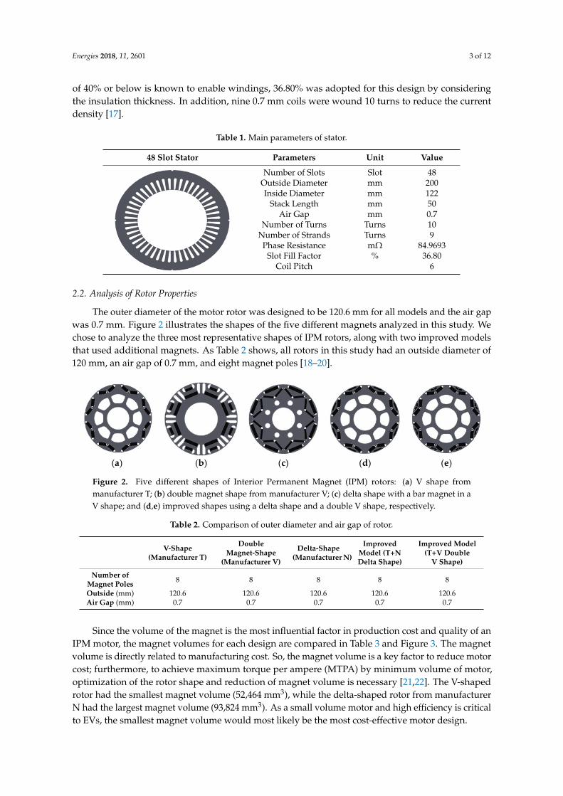
gap was 0.7 mm. Figure 2 illustrates the shapes of the five different magnets analyzed in this study.
We chose to analyze the three most representative shapes of IPM rotors, along with two improved
models that used additional magnets. As Table 2 shows, all rotors in this study had an outside
diameter of 120 mm, an air gap of 0.7 mm, and eight magnet poles [18–20].
(a) (b) (c) (d) (e)
Figure 2. Five different shapes of Interior Permanent Magnet (IPM) rotors: (a) V shape from
manufacturer T; (b) double magnet shape from manufacturer V; (c) delta shape with a bar magnet in
a V shape; and (d,e) improved shapes using a delta shape and a double V shape, respectively.
Table 2. Comparison of outer diameter and air gap of rotor.
V-Shape
(Manufacturer T)
Double
Magnet-Shape
(Manufacturer V)
Delta-Shape
(Manufacturer
N)
Improved
Model (T+N
Delta Shape)
Improved Model
(T+V Double V
Shape)
Number of
Magnet Poles 8 8 8 8 8
Outside (mm) 120.6 120.6 120.6 120.6 120.6
Air Gap (mm) 0.7 0.7 0.7 0.7 0.7
Since the volume of the magnet is the most influential factor in production cost and quality of
an IPM motor, the magnet volumes for each design are compared in Table 3 and Figure 3. The
magnet volume is directly related to manufacturing cost. So, the magnet volume is a key factor to
reduce motor cost; furthermore, to achieve maximum torque per ampere (MTPA) by minimum
volume of motor, optimization of the rotor shape and reduction of magnet volume is necessary
[21,22]. The V-shaped rotor had the smallest magnet volume (52,464 mm3), while the delta-shaped
rotor from manufacturer N had the largest magnet volume (93,824 mm3). As a small volume motor
and high efficiency is critical to EVs, the smallest magnet volume would most likely be the most
cost-effective motor design.
Number of Slots Slot 48Outside Diameter mm 200Inside Diameter mm 122
Stack Length mm 50Air Gap mm 0.7
Number of Turns Turns 10Number of Strands Turns 9
Phase Resistance mΩ 84.9693Slot Fill Factor % 36.80
Coil Pitch 6
2.2. Analysis of Rotor Properties
The outer diameter of the motor rotor was designed to be 120.6 mm for all models and the air gapwas 0.7 mm. Figure 2 illustrates the shapes of the five different magnets analyzed in this study. Wechose to analyze the three most representative shapes of IPM rotors, along with two improved modelsthat used additional magnets. As Table 2 shows, all rotors in this study had an outside diameter of120 mm, an air gap of 0.7 mm, and eight magnet poles [18–20].
Energies 2018, 11, x 3 of 12
order to form a sinusoidal back-EMF (B-EMF) at the stator, distributed windings were designed. As
a space factor of 40% or below is known to enable windings, 36.80% was adopted for this design by
considering the insulation thickness. In addition, nine 0.7 mm coils were wound 10 turns to reduce
the current density [17].
Table 1. Main parameters of stator.
48 Slot Stator Parameters Unit Value
Number of Slots Slot 48
Outside Diameter mm 200
Inside Diameter mm 122
Stack Length mm 50
Air Gap mm 0.7
Number of Turns Turns 10
Number of Strands Turns 9
Phase Resistance mΩ 84.9693
Slot Fill Factor % 36.80
Coil Pitch 6
2.2. Analysis of Rotor Properties
The outer diameter of the motor rotor was designed to be 120.6 mm for all models and the air
gap was 0.7 mm. Figure 2 illustrates the shapes of the five different magnets analyzed in this study.
We chose to analyze the three most representative shapes of IPM rotors, along with two improved
models that used additional magnets. As Table 2 shows, all rotors in this study had an outside
diameter of 120 mm, an air gap of 0.7 mm, and eight magnet poles [18–20].
(a) (b) (c) (d) (e)
Figure 2. Five different shapes of Interior Permanent Magnet (IPM) rotors: (a) V shape from
manufacturer T; (b) double magnet shape from manufacturer V; (c) delta shape with a bar magnet in
a V shape; and (d,e) improved shapes using a delta shape and a double V shape, respectively.
Table 2. Comparison of outer diameter and air gap of rotor.
V-Shape
(Manufacturer T)
Double
Magnet-Shape
(Manufacturer V)
Delta-Shape
(Manufacturer
N)
Improved
Model (T+N
Delta Shape)
Improved Model
(T+V Double V
Shape)
Number of
Magnet Poles 8 8 8 8 8
Outside (mm) 120.6 120.6 120.6 120.6 120.6
Air Gap (mm) 0.7 0.7 0.7 0.7 0.7
Since the volume of the magnet is the most influential factor in production cost and quality of
an IPM motor, the magnet volumes for each design are compared in Table 3 and Figure 3. The
magnet volume is directly related to manufacturing cost. So, the magnet volume is a key factor to
reduce motor cost; furthermore, to achieve maximum torque per ampere (MTPA) by minimum
volume of motor, optimization of the rotor shape and reduction of magnet volume is necessary
[21,22]. The V-shaped rotor had the smallest magnet volume (52,464 mm3), while the delta-shaped
rotor from manufacturer N had the largest magnet volume (93,824 mm3). As a small volume motor
and high efficiency is critical to EVs, the smallest magnet volume would most likely be the most
cost-effective motor design.
Figure 2. Five different shapes of Interior Permanent Magnet (IPM) rotors: (a) V shape frommanufacturer T; (b) double magnet shape from manufacturer V; (c) delta shape with a bar magnet in aV shape; and (d,e) improved shapes using a delta shape and a double V shape, respectively.
Table 2. Comparison of outer diameter and air gap of rotor.
V-Shape(Manufacturer T)
DoubleMagnet-Shape
(Manufacturer V)
Delta-Shape(Manufacturer N)
ImprovedModel (T+NDelta Shape)
Improved Model(T+V Double
V Shape)
Number ofMagnet Poles 8 8 8 8 8
Outside (mm) 120.6 120.6 120.6 120.6 120.6Air Gap (mm) 0.7 0.7 0.7 0.7 0.7
Since the volume of the magnet is the most influential factor in production cost and quality of anIPM motor, the magnet volumes for each design are compared in Table 3 and Figure 3. The magnetvolume is directly related to manufacturing cost. So, the magnet volume is a key factor to reduce motorcost; furthermore, to achieve maximum torque per ampere (MTPA) by minimum volume of motor,optimization of the rotor shape and reduction of magnet volume is necessary [21,22]. The V-shapedrotor had the smallest magnet volume (52,464 mm3), while the delta-shaped rotor from manufacturerN had the largest magnet volume (93,824 mm3). As a small volume motor and high efficiency is criticalto EVs, the smallest magnet volume would most likely be the most cost-effective motor design.

Energies 2018, 11, 2601 4 of 12
Table 3. Analysis of rotor magnet volume.
V-Shape(Manufacturer T)
DoubleMagnet-Shape
(Manufacturer V)
Delta-Shape(Manufacturer N)
ImprovedModel (T+NDelta Shape)
Improved Model(T+V Double
V-Shape)
MagnetVolume (mm3) 52,464 63,200 93,824 74,864 60,736
Energies 2018, 11, x 4 of 12
Table 3. Analysis of rotor magnet volume.
V-Shape
(Manufacturer
T)
Double
Magnet-Shape
(Manufacturer V)
Delta-Shape
(Manufacturer N)
Improved Model
(T+N Delta Shape)
Improved Model
(T+V Double
V-Shape)
Magnet
Volume (mm3) 52,464 63,200 93,824 74,864 60,736
Figure 3. Comparison of Rotor Magnet Volume.
3. Comparative Analysis
In order to analyze the characteristics of IPM rotors according to their shape, three main factors
were analyzed. Table 4 shows the critical factors analyzed in subsequent sections [23,24].
Table 4. Analysis of rotor magnet volume.
No Analysis Factor Necessity of Analysis
1 Back EMF Determines the maximum range of motor rotation
2 Torque ripple or cogging torque Very influential on noise and vibration
3 Torque As the magnitude of a force generated according to velocity, torque
is very influential in setting a domain of operation.
4 Efficiency Closely related to the power consumption of a vehicle
For analysis, we used the motor electromagnetic field analysis tool, “JMAG” (ver. 14.1), with
data produced through simulation analysis.
3.1. Analysis of B-EMF as a Function of Rotor Shapes
A no-load voltage analysis was conducted by applying a rotational speed of 1000 rpm to induce
and analyze linear voltage values. Based on the results of B-EMF voltage analysis, a distributed
winding was designed for the stator so that the B-EMF voltage waveforms were similar to a
sinusoid. The V-shaped motor from manufacturer T was the most sinusoidal.
Table 5 presents B-EMF voltages and constants; a back-EMF analysis was performed for the five
rotor shapes, as shown in Figure 4. The improved delta shape, which was based on the V-shape from
manufacturer T, had the highest B-EMF voltage (28.68 V), and the double magnet shape of
manufacturer T showed the lowest B-EMF voltage (20.80 V). As the no-load voltage decreased, the
no-load speed increased.
The V shape from manufacturer T utilized more magnetic flux than the other shapes; thus, it
had a higher B-EMF voltage than that of the double magnet-shape. This indicates that the V shape
using a small amount of current is suitable for generating high power. Moreover, as the V shape has
Figure 3. Comparison of Rotor Magnet Volume.
3. Comparative Analysis
In order to analyze the characteristics of IPM rotors according to their shape, three main factorswere analyzed. Table 4 shows the critical factors analyzed in subsequent sections [23,24].
Table 4. Analysis of rotor magnet volume.
No Analysis Factor Necessity of Analysis
1 Back EMF Determines the maximum range of motor rotation2 Torque ripple or cogging torque Very influential on noise and vibration
3 Torque As the magnitude of a force generated according to velocity,torque is very influential in setting a domain of operation.
4 Efficiency Closely related to the power consumption of a vehicle
For analysis, we used the motor electromagnetic field analysis tool, “JMAG” (ver. 14.1), with dataproduced through simulation analysis.
3.1. Analysis of B-EMF as a Function of Rotor Shapes
A no-load voltage analysis was conducted by applying a rotational speed of 1000 rpm to induceand analyze linear voltage values. Based on the results of B-EMF voltage analysis, a distributedwinding was designed for the stator so that the B-EMF voltage waveforms were similar to a sinusoid.The V-shaped motor from manufacturer T was the most sinusoidal.
Table 5 presents B-EMF voltages and constants; a back-EMF analysis was performed for the fiverotor shapes, as shown in Figure 4. The improved delta shape, which was based on the V-shapefrom manufacturer T, had the highest B-EMF voltage (28.68 V), and the double magnet shape ofmanufacturer T showed the lowest B-EMF voltage (20.80 V). As the no-load voltage decreased, theno-load speed increased.
The V shape from manufacturer T utilized more magnetic flux than the other shapes; thus, ithad a higher B-EMF voltage than that of the double magnet-shape. This indicates that the V shapeusing a small amount of current is suitable for generating high power. Moreover, as the V shapehas a more sinusoidal waveform than the delta shape, it likely is more advantageous for minimizingtorque ripples.

Energies 2018, 11, 2601 5 of 12
Table 5. B-EMF voltage and constants.
V Shape(Manufacturer T)
Double MagnetShape
(Manufacturer V)
Delta Shape(Manufacturer N)
ImprovedModel (T+NDelta Shape)
Improved Model(T+V Double
V-Shape)
B-EMF Voltage(V_rms) 27.13 20.80 27.9731 28.68 27.17
B-EMF VoltageConstants
(V_rms/rpm)0.0271 0.0208 0.02797 0.02868 0.02717
Energies 2018, 11, x 5 of 12
a more sinusoidal waveform than the delta shape, it likely is more advantageous for minimizing
torque ripples.
Table 5. B-EMF voltage and constants.
V Shape
(Manufacturer T)
Double Magnet
Shape
(Manufacturer V)
Delta Shape
(Manufacturer N)
Improved Model
(T+N Delta
Shape)
Improved Model
(T+V Double
V-Shape)
B-EMF Voltage
(V_rms) 27.13 20.80 27.9731 28.68 27.17
B-EMF Voltage
Constants
(V_rms/rpm)
0.0271 0.0208 0.02797 0.02868 0.02717
(a)
(b)
Figure 4. B-EMF Wave and No-Load Voltage: (a) B-EMF Wave; (b) B-EMF No-Load Voltage.
Figure 4. B-EMF Wave and No-Load Voltage: (a) B-EMF Wave; (b) B-EMF No-Load Voltage.
3.2. Analysis of Cogging Torque and Torque Ripple
Figure 5 shows the results of our electromagnetic field analysis for cogging torque and torqueripple. Since the improved delta V shape from manufacturer T was designed to arrange the magnetsclose to the stator in order to utilize magnetic flux more effectively, it had the highest cogging torque(2.875 Nm). The best cogging torque was 0.9678 Nm, which was produced by the double magnet-shapefrom manufacturer V; the difference between this and the V-shaped rotor was 1.9 Nm. On the otherhand, the cogging torque of the V shape was 1.898 Nm, but the improved double V-shape was1.798 Nm, a difference of just 0.1 Nm. Consequently, a double magnet-shaped rotor was shown to beadvantageous for cogging torque, and using this shape would likely reduce design time [25].

Energies 2018, 11, 2601 6 of 12
Energies 2018, 11, x 6 of 12
3.2. Analysis of Cogging Torque and Torque Ripple
Figure 5 shows the results of our electromagnetic field analysis for cogging torque and torque
ripple. Since the improved delta V shape from manufacturer T was designed to arrange the magnets
close to the stator in order to utilize magnetic flux more effectively, it had the highest cogging torque
(2.875 Nm). The best cogging torque was 0.9678 Nm, which was produced by the double
magnet-shape from manufacturer V; the difference between this and the V-shaped rotor was 1.9
Nm. On the other hand, the cogging torque of the V shape was 1.898 Nm, but the improved double
V-shape was 1.798 Nm, a difference of just 0.1 Nm. Consequently, a double magnet-shaped rotor
was shown to be advantageous for cogging torque, and using this shape would likely reduce design
time [25].
(a)
(b)
Energies 2018, 11, x 7 of 12
(c)
Figure 5. Analysis of cogging torque and torque ripple: (a) Comparison of torque ripples; (b)
Comparison of torque ripples in the analysis of current source at 0° current phase angle; (c)
Comparison of torque ripples in the analysis of current source at 40° current phase angle.
4. Results
4.1. Speed-Torque and Speed-Efficiency Analysis
Another electromagnetic analysis was conducted by applying constant current at a variety of
speeds. The range of the analysis was performed at 1000–10,000 rpm in consideration of B-EMF
voltages. Initially, the analysis used magnet torques without controlling phase angles. As is widely
known, magnetic reluctance in an IPM motor, i.e., saliency, an additional torque component is
developed. By phase angle control, the torque is increased for a given current magnitude.
Consequentially, maximum torque occurs for a current phase of 35°–45°; this study conducted a
comparative analysis at a current phase angle of 40° in order to examine the characteristics of
maximum torque.
As shown in Figure 6, in order to analyze the impact of the d-axis and the q-axis, the current of
the q-axis was held at zero and the torque and efficiency due to the d-axis were analyzed. The
analysis showed that the delta-shape from manufacturer N had the highest torque (77.65 Nm)
because of its large magnet volume, and also because it has the widest magnet surface to generate an
active magnetic flux. The V-shape, with the smallest magnet surface for generating active magnetic
flux had a torque of 66.16 Nm, which was lower than that of the delta-shape by 11.49 Nm. Table 6
compares torque characteristics according to speed.
Table 6. Comparison of speed-torque characteristics according to rotor shapes. (phase angle of 40°)
RPM
V Shape
(Manufacturer
T) (Nm)
Double Magnet Shape
(Manufacturer V) (Nm)
Delta Shape
(Manufacturer N)
(Nm)
Improved Model
(T+N Delta Shape)
(Nm)
Improved Model
(T+V Double
V-Shape) (Nm)
1000 66.12894 55.14583 77.65978 76.62068 71.49971
2000 66.16147 55.16258 77.65832 76.62819 71.514
3000 66.16877 55.16563 77.65658 76.63369 71.51918
4000 66.16998 55.17346 77.66459 76.6316 71.52973
5000 47.48419 38.72789 52.89918 53.16905 50.03325
6000 28.56902 21.60797 29.9703 30.90529 29.45301
7000 21.88614 16.23352 22.45951 23.38148 22.36065
8000 17.2897 12.85844 17.62589 18.32735 17.55764
Figure 5. Analysis of cogging torque and torque ripple: (a) Comparison of torque ripples;(b) Comparison of torque ripples in the analysis of current source at 0 current phase angle;(c) Comparison of torque ripples in the analysis of current source at 40 current phase angle.

Energies 2018, 11, 2601 7 of 12
4. Results
4.1. Speed-Torque and Speed-Efficiency Analysis
Another electromagnetic analysis was conducted by applying constant current at a variety ofspeeds. The range of the analysis was performed at 1000–10,000 rpm in consideration of B-EMFvoltages. Initially, the analysis used magnet torques without controlling phase angles. As iswidely known, magnetic reluctance in an IPM motor, i.e., saliency, an additional torque componentis developed. By phase angle control, the torque is increased for a given current magnitude.Consequentially, maximum torque occurs for a current phase of 35–45; this study conducted acomparative analysis at a current phase angle of 40 in order to examine the characteristics ofmaximum torque.
As shown in Figure 6, in order to analyze the impact of the d-axis and the q-axis, the current ofthe q-axis was held at zero and the torque and efficiency due to the d-axis were analyzed. The analysisshowed that the delta-shape from manufacturer N had the highest torque (77.65 Nm) because of itslarge magnet volume, and also because it has the widest magnet surface to generate an active magneticflux. The V-shape, with the smallest magnet surface for generating active magnetic flux had a torqueof 66.16 Nm, which was lower than that of the delta-shape by 11.49 Nm. Table 6 compares torquecharacteristics according to speed.
Table 6. Comparison of speed-torque characteristics according to rotor shapes (phase angle of 40).
RPMV Shape
(ManufacturerT) (Nm)
DoubleMagnet Shape(Manufacturer
V) (Nm)
Delta Shape(Manufacturer
N) (Nm)
ImprovedModel (T+NDelta Shape)
(Nm)
ImprovedModel (T+V
DoubleV-Shape) (Nm)
1000 66.12894 55.14583 77.65978 76.62068 71.499712000 66.16147 55.16258 77.65832 76.62819 71.5143000 66.16877 55.16563 77.65658 76.63369 71.519184000 66.16998 55.17346 77.66459 76.6316 71.529735000 47.48419 38.72789 52.89918 53.16905 50.033256000 28.56902 21.60797 29.9703 30.90529 29.453017000 21.88614 16.23352 22.45951 23.38148 22.360658000 17.2897 12.85844 17.62589 18.32735 17.557649000 12.9869 9.78588 13.24661 13.66213 13.08482
10,000 8.28681 6.32922 8.49809 8.67869 8.27965
Next, the impact of the q-axis was analyzed by applying a current phase angle of 40. Whenthe current phase angle is controlled, magnet torques and reluctance torques are combined, whichenabled us to identify the maximum torque. As shown in Figure 7, the improved double V shape frommanufacturer T had the best torque (107.98 Nm) and also exhibited high torques at rotational speedsof 5000–10,000 rpm. Data showing a comparison of speed-torque characteristics according to rotorshape (phase angle of 40) is shown in Table 7.

Energies 2018, 11, 2601 8 of 12
Energies 2018, 11, x 8 of 12
9000 12.9869 9.78588 13.24661 13.66213 13.08482
10,000 8.28681 6.32922 8.49809 8.67869 8.27965
(a)
(b)
Figure 6. Current analysis of torque, ripple, efficiency comparison, and magnetic flux density at 0˚ of
phase angle: (a) Comparison of torque according to speed; (b) Comparison of efficiency according to
speed.
Next, the impact of the q-axis was analyzed by applying a current phase angle of 40°. When the
current phase angle is controlled, magnet torques and reluctance torques are combined, which
enabled us to identify the maximum torque. As shown in Figure 7, the improved double V shape
from manufacturer T had the best torque (107.98 Nm) and also exhibited high torques at rotational
speeds of 5000–10,000 rpm. Data showing a comparison of speed-torque characteristics according to
rotor shape (phase angle of 40°) is shown in Table 7.
Figure 6. Current analysis of torque, ripple, efficiency comparison, and magnetic flux density at 0
of phase angle: (a) Comparison of torque according to speed; (b) Comparison of efficiency accordingto speed.
Table 7. Comparison of speed-torque characteristics according to rotor shapes (phase angle of 40).
RPMV Shape
(ManufacturerT) (Nm)
DoubleMagnet-Shape
(Manufacturer V)(Nm)
Delta Shape(Manufacturer
N) (Nm)
Improved Model(T+N Delta Shape)
(Nm)
Improved Model(T+V Double
V-Shape) (Nm)
1000 107.07544 84.50443 104.66107 109.14068 107.987622000 107.06992 84.50021 104.66051 109.13429 107.984973000 107.07162 84.49209 104.65735 109.13434 107.980344000 107.06842 84.50367 104.6514 109.13934 107.976485000 70.46591 54.01324 64.72424 70.05181 69.941646000 35.90096 28.13232 32.53424 35.60729 35.380567000 25.0925 20.39196 23.34639 25.08518 24.784098000 18.50735 15.46581 17.69671 18.6181 18.327149000 12.98148 10.91558 12.77176 13.1783 12.91309
10,000 7.63406 6.34526 7.66694 7.81597 7.61829

Energies 2018, 11, 2601 9 of 12
Energies 2018, 11, x 9 of 12
Table 7. Comparison of speed-torque characteristics according to rotor shapes. (phase angle of 40°)
RPM
V Shape
(Manufacturer T)
(Nm)
Double
Magnet-Shape
(Manufacturer V)
(Nm)
Delta Shape
(Manufacturer N)
(Nm)
Improved Model
(T+N Delta
Shape) (Nm)
Improved Model
(T+V Double
V-Shape) (Nm)
1000 107.07544 84.50443 104.66107 109.14068 107.98762
2000 107.06992 84.50021 104.66051 109.13429 107.98497
3000 107.07162 84.49209 104.65735 109.13434 107.98034
4000 107.06842 84.50367 104.6514 109.13934 107.97648
5000 70.46591 54.01324 64.72424 70.05181 69.94164
6000 35.90096 28.13232 32.53424 35.60729 35.38056
7000 25.0925 20.39196 23.34639 25.08518 24.78409
8000 18.50735 15.46581 17.69671 18.6181 18.32714
9000 12.98148 10.91558 12.77176 13.1783 12.91309
10,000 7.63406 6.34526 7.66694 7.81597 7.61829
(a)
(b)
Figure 7. Analysis of torque and efficiency according to speed (phase angle controlled at 40°): (a)
Comparison of torque according to speed (phase angle controlled at 40°); (b) Comparison of
efficiency according to speed (phase angle controlled at 40°).
Figure 7. Analysis of torque and efficiency according to speed (phase angle controlled at 40):(a) Comparison of torque according to speed (phase angle controlled at 40); (b) Comparison ofefficiency according to speed (phase angle controlled at 40).
4.2. Comparison of Power and Other Factors
The manufacturing cost is mostly influenced by magnet shape and volume of the permanentmagnet. As discussed, the main goal of this study was to increase manufacturing efficiency anddecrease the effort and time needed for selection of the design concept. Therefore, in order to achieveMTPA with a minimum volume of motor, optimization of the rotor shape and reduction of magnetvolume are important considerations in rotor design.
Figure 8 shows a comparison between power and other factors, based on previous analyses.As shown in Figure 8a, the double magnet shape had the lowest power, reflecting the lowest torque; thedelta shape was the highest-power rotor shape. Except the double magnet shape, the comparison showsthat power and manufacturing cost have a linear proportional relationship, because of complicatedshapes and relatively high magnet volumes. Based on Figure 8a,b shows a comparison of efficiencyand power. Mechanical power output is calculated based on the torque and speed required, and

Energies 2018, 11, 2601 10 of 12
electric motor efficiency is the ratio between output power and input power. Therefore, efficiencyis mainly related to power, and Figure 8b shows a linear proportional relationship between powerand efficiency.
Energies 2018, 11, x 10 of 12
4.2. Comparison of Power and Other Factors
The manufacturing cost is mostly influenced by magnet shape and volume of the permanent
magnet. As discussed, the main goal of this study was to increase manufacturing efficiency and
decrease the effort and time needed for selection of the design concept. Therefore, in order to
achieve MTPA with a minimum volume of motor, optimization of the rotor shape and reduction of
magnet volume are important considerations in rotor design.
Figure 8 shows a comparison between power and other factors, based on previous analyses. As
shown in Figure 8a, the double magnet shape had the lowest power, reflecting the lowest torque;
the delta shape was the highest-power rotor shape. Except the double magnet shape, the
comparison shows that power and manufacturing cost have a linear proportional relationship,
because of complicated shapes and relatively high magnet volumes. Based on Figure 8a,b shows a
comparison of efficiency and power. Mechanical power output is calculated based on the torque
and speed required, and electric motor efficiency is the ratio between output power and input
power. Therefore, efficiency is mainly related to power, and Figure 8b shows a linear proportional
relationship between power and efficiency.
(a) (b)
Figure 8. Comparison of power and other factors: (a) Comparison of manufacturing cost and power;
(b) Comparison of efficiency and power.
5. Conclusions
This study analyzed the design and electromechanical properties of IMP motors for electric
vehicles as a function of rotor shape; various factors (e.g., speed, torque, torque ripple and B-EMF
voltage) were compared. The main goal of this study was to reduce the time required to design a
rotor with the maximum power density for an IPM motor. The findings of this study will be useful
for the confined space typical of EVs. Further study will fabricate an actual V-shaped rotor and
verify the reliability of the electromagnetic analysis
The sizes of outer diameters were fixed for both rotors and stators. The same stator shape and
winding design was applied. Different arrangements of magnets were adopted for each rotor shape
in order to obtain various results in speed, torque, efficiency, ripple, etc. In order to analyze the
impact of both the d- and q-axis, the current of the q-axis was controlled at zero and the
electromagnetic characteristics due to the d-axis were examined. The delta shape from manufacturer
N had the highest torque (77.65 Nm) up to a rotation speed of 4000 rpm, and a higher torque by
about 1Nm between 5000 and 10,000 rpm.
The impact of the q-axis was analyzed by applying a current phase angle of 40°. When the
current phase angle was controlled, magnet torques and reluctance torques were combined, which
enabled us to identify the maximum torque. The improved double V shape from manufacturer T
had the best torque (107.98 Nm). The V shape from manufacturer T showed higher torques at
Figure 8. Comparison of power and other factors: (a) Comparison of manufacturing cost and power;(b) Comparison of efficiency and power.
5. Conclusions
This study analyzed the design and electromechanical properties of IMP motors for electricvehicles as a function of rotor shape; various factors (e.g., speed, torque, torque ripple and B-EMFvoltage) were compared. The main goal of this study was to reduce the time required to design a rotorwith the maximum power density for an IPM motor. The findings of this study will be useful for theconfined space typical of EVs. Further study will fabricate an actual V-shaped rotor and verify thereliability of the electromagnetic analysis.
The sizes of outer diameters were fixed for both rotors and stators. The same stator shape andwinding design was applied. Different arrangements of magnets were adopted for each rotor shape inorder to obtain various results in speed, torque, efficiency, ripple, etc. In order to analyze the impactof both the d- and q-axis, the current of the q-axis was controlled at zero and the electromagneticcharacteristics due to the d-axis were examined. The delta shape from manufacturer N had the highesttorque (77.65 Nm) up to a rotation speed of 4000 rpm, and a higher torque by about 1Nm between5000 and 10,000 rpm.
The impact of the q-axis was analyzed by applying a current phase angle of 40. When the currentphase angle was controlled, magnet torques and reluctance torques were combined, which enabled usto identify the maximum torque. The improved double V shape from manufacturer T had the besttorque (107.98 Nm). The V shape from manufacturer T showed higher torques at rotational speeds of5000–10,000 rpm. In addition, the V shape had a magnet volume of 52,464 mm3, while the improveddouble V shape had a higher magnet volume of 60,736 mm3, indicating that the V-shape, with 13.6%less magnet volume, would be more advantageous for reducing the price of a motor.
Author Contributions: Conceptualization, M.-H.H. and H.-R.C.; Data curation, D.-H.K. and J.-H.H.; Formalanalysis, M.-H.H.; Methodology, S.Y.J.; Supervision, H.-R.C.; Validation, D.-H.K. and J.-H.H.; Visualization,M.-H.H.; Writing—original draft, M.-H.H.; Writing—review & editing, H.-R.C.
Funding: This research was funded by the support of the Korea Institute of Industrial Technology as “VariableArchitecture Powertrain Platform and Self-driving Factor Technology Development for Industrial EV Self-drivingVehicle” KITECH EO-18-0020.
Conflicts of Interest: The authors declare no conflicts of interest.

Energies 2018, 11, 2601 11 of 12
References
1. De Santiago, J.; Bernhoff, H.; Ekergård, B.; Eriksson, S.; Ferhatovic, S.; Waters, R.; Leijon, M. Electricalmotor drivelines in commercial all-electric vehicles: A review. IEEE Trans. Veh. Technol. 2012, 61, 475–484.[CrossRef]
2. Bazzi, A. Electric machines and energy storage technologies in EVs and HEVs for over a century.In Proceedings of the IEEE International Electric Machines & Drives Conference, Chicago, IL, USA,12–15 May 2013.
3. Zhu, Z.Q.; Howe, D. Electrical machines and drives for electric, hybrid, and fuel cell vehicles. Proc. IEEE2007, 95, 746–765. [CrossRef]
4. Miyama, Y.; Hijikata, H.; Sakai, Y.; Akatsu, K.; Arita, H.; Daikoku, A. Variable characteristics technique onpermanent magnet motor for electric vehicles traction system. In Proceedings of the 2015 IEEE InternationalElectric Machines & Drives Conference (IEMDC), Coeur d’Alene, ID, USA, 10–13 May 2015.
5. Yang, Y.; Arshad-Ali, K.; Roeleveld, J.; Emadi, A. State-of-the-art electrified powertrains: Hybrid, plug-inhybrid, and electric vehicles. Int. J. Powertrains 2016. [CrossRef]
6. Wang, A.; Li, H.; Lu, W.; Zhao, H. Influence of skewed and segmented magnet rotor on IPM machineperformance and ripple torque for electric traction. In Proceedings of the IEEE International ElectricMachines and Drives Conference, Miami, FL, USA, 3–6 May 2009.
7. Yang, Y.; Schofield, N.; Emadi, A. Integrated Electro-Mechanical Double-Rotor Compound HybridTransmissions for Hybrid Electric Vehicles. IEEE Trans. Veh. Technol. 2016. [CrossRef]
8. Lee, B.; Kim, K.; Jung, J.; Kim, Y. Temperature Estimation of IPMSM using Thermal Equivalent Circuit.IEEE Trans. Magn. 2016, 48, 2949–2952. [CrossRef]
9. Miller, T.J.E., Jr. Hendershot: Design of Brushless Permanent Magnet Machines; Magna Physics Corporation:Hillsboro, OH, USA, 1991.
10. Zhang, Y.; Cao, W.P.; Morrow, J. Interior Permanent Magnet Motor Parameter and Torque Ripple Analysisfor EV Traction. In Proceedings of the 2015 IEEE International Conference on Applied Superconductivityand Electromagnetic Devices (ASEMD), Shanghai, China, 20–23 November 2015.
11. Kioumarsi, A.; Moallem, M.; Fahimi, B. Mitigation of Torque Ripple in Interior Permanent Magnet Motorsby Optimal Shape Design. IEEE Trans. Magn. 2006, 42, 3708–3710. [CrossRef]
12. Yang, Y.; Castano, S.; Yang, R.; Kasprzak, M.; Bilgin, B.; Sathyan, A.; Dadkhah, H.; Emadi, A. Designand Comparison of Interior Permanent Magnet Motor Topologies for Traction Application. IEEE Trans.Transp. Electrif. 2017, 3, 4–9. [CrossRef]
13. Liu, X.; Lin, Q.; Fu, W. Optimal Design of Permanent Magnet Arrangement in Synchronous Motors. Energies2017, 10, 1700. [CrossRef]
14. Wang, A.; Jia, Y.; Soong, W.L. Comparison of Five Topologies for an Interior Permanent-Magnet Machine fora Hybrid Electric Vehicle. IEEE Trans. Magn. 2011, 47, 3606–3609. [CrossRef]
15. Ma, F.; Yin, H.; Wei, L.; Tian, G.; Gao, H. Design and Optimization of IPM Motor Considering Flux WeakeningCapability and Vibration for Electric Vehicle Applications. Sustainability 2018, 10, 1533. [CrossRef]
16. Soleimani, J.; Vahedi, A.; Mirimani, S.M. Inner permanent magnet synchronous machine optimization forHEV traction drive application in order to achieve maximum torque per ampere. Iran. J. Electr. Electron. Eng.2011, 7, 241–247.
17. Ohnishi, T.; Takahashi, N. Optimal design of efficient IPM motor using finite element method.IEEE Trans. Magn. 2000, 36, 3537–3539. [CrossRef]
18. Takahashi, N.; Natsumeda, M.; Muramatsu, K.; Yamada, C.; Ogawa, M.; Kobayashi, S.; Kuwabara, T.Optimization of permanent magnet type of retarder using 3-D finite element method and direct searchmethod. IEEE Trans. Magn. 1998, 34, 2996–2999. [CrossRef]
19. Wu, S.; Tian, L.; Cui, S. A comparative study of the interior permanent magnet electrical machine’s rotorconfigurations for a single shaft hybrid electric bus. In Proceedings of the 2008 IEEE Vehicle Power andPropulsion Conference, Harbin, China, 3–5 September 2008. [CrossRef]
20. Sorgdrager, A.J.; Grobler, A.J. Influence of magnet size and rotor topology on the air-gap flux density of aradial flux PMSM. In Proceedings of the 2013 IEEE International Conference on Industrial Technology (ICIT),Cape Town, South Africa, 25–28 February 2013. [CrossRef]

Energies 2018, 11, 2601 12 of 12
21. Kim, T.; Chang, J. Influence of Cogging Torque Reduction Method on Torque Ripple in a Surface-MountedPermanent Magnet Synchronous Motor. J. Magn. 2012, 17, 111–113. [CrossRef]
22. Kim, J.; Seo, J.; Jung, H.; Won, C. Analysis and Design of a Novel-Shape Permanent Magnet SynchronousMotor for Minimization of Torque Ripple and Iron Loss. J. Magn. 2014, 4, 413–415. [CrossRef]
23. Kahourzade, S.; Mahmoudi, A.; Abdul Rahim, N.; Ping, H. Sizing equation and Finite Element Analysisoptimum design of axial-flux permanent-magnet motor for electric vehicle direct drive. In Proceedings of the2012 IEEE International Power Engineering and Optimization Conference, Melaka, Malaysia, 6–7 June 2012.
24. Mahmoudi, A.; Rahim, N.A.; Ping, H.W. Axial-flux permanent-magnet motor design for electric vehicledirect drive using sizing equation and finite element analysis. Prog. Electromagn. Res. 2012, 122, 467–496.[CrossRef]
25. Lukic, S.M.; Emado, A. Modeling of electric machines for automotive applications using efficiency maps.In Proceedings of the Electrical Insulation Conference and Electrical Manufacturing and Coil WindingTechnology Conference (Cat. No.03CH37480), Indianapolis, IN, USA, 25–28 February 2003. [CrossRef]
© 2018 by the authors. Licensee MDPI, Basel, Switzerland. This article is an open accessarticle distributed under the terms and conditions of the Creative Commons Attribution(CC BY) license (http://creativecommons.org/licenses/by/4.0/).