DESIGN AND ANALYSIS OF COMPOSITE LEAF SPRING
8
www.smenec.org 76 © SME *Corresponding Author - E- mail: [email protected] ABSTRACT This paper describes the design and experimental analysis of composite leaf spring made of glass fibre reinforced polymer. The main aim is to compare the load-carrying capacity, stiffness and weight savings of composite leaf spring with that of steel leaf spring. The design constraints are stress and deflection. The dimensions of an existing conventional steel leaf spring of a light commercial vehicle were considered for the present work. A traditional composite multi-leaf spring was fabricated with the same dimensions using E- Glass/Epoxy unidirectional laminates. Static analysis of 2D model of conventional leaf spring has also been performed using ANSYS 10 and compared with experimental results. Finite element analysis with a full load on the 3-D model of composite multi- leaf spring was performed using ANSYS, and the analytical results were compared with experimental results. Keywords: Composite Leaf spring, E-Glass/Epoxy, Solid works, ANSYS 1. Introduction A leaf spring is a simple form of spring commonly used for the suspension in wheeled vehicles. Originally called a laminated or carriage spring, and sometimes referred to as a semi-elliptical spring or cart spring, it is one of the oldest forms of springing, dating back to medieval times. A leaf spring takes the form of a slender arc- shaped length of spring steel of rectangular cross- section. The centre of the arc provides a location for the axle, while tie holes are provided at either end for attaching to the vehicle body. For very heavy vehicles, a leaf spring can be made from several leaves stacked on top of each other in several layers, often with progressively shorter leaves. Leaf springs can serve to locate and to some extent damping as well as springing functions. Vinkel Arora et al. [1] performed eye design analysis of single leaf spring in automotive vehicles using CAE tools. For this reason, manufacturers have experimented with mono-leaf springs piston to compress or eject the fluid in the cylinder. A leaf spring can either be attached directly to the frame at both ends or connected directly at one end, usually the front, with the other end attached through a shackle, a short swinging arm. K. K. Jadhao and R. S. Dalu [2] carried out an experimental investigation & numerical analysis on composite leaf spring. M. M. Patunkar and D. R. Dolas [3] modeled and analyzed composite leaf spring under the Static Load condition by using FEA. There are two basic types of leaf springs, mono-leaf and multi- leaf. A mono-leaf spring has only one arc-shaped steel strip, which is usually very thick in the middle with much thinner ends. A multi-leaf spring was constructed of several arc-shaped steel strips of varying lengths that are stacked together with the longest strip at the top, and the shortest strip at the bottom. Sorathiya Mehul et al. [4] analyzed the laminated leaf spring using FEA for light vehicle mini truck. Fig.1 shows the pictorial representation of laminated leaf spring. To convert the reciprocating motion into rotation, the crankshaft has "crank throws" or "crankpins", additional bearing surfaces whose axis is offset from that of the crank, to which the "big ends" of the connecting rods from each cylinder attach. Fig. 1 Laminated Leaf Spring Journal of Manufacturing Engineering, September 2020, Vol. 15, Issue. 3, pp 076-083 DESIGN AND ANALYSIS OF COMPOSITE LEAF SPRING *Prasanna Nagasai B 1 , Srikanth S 2 and Tarun D 3 1 Department of Manufacturing Engineering, Annamalai University, Chidambaram, Tamil Nadu-608002, India 2, 3 Department of Mechanical Engineering, Gudlavalleru Engineering College, Vijayawada, Andhra Pradesh-521356, India https://doi.org/10.37255/jme.v15i3pp76-83 .
-
Upload
khangminh22 -
Category
Documents
-
view
2 -
download
0
Transcript of DESIGN AND ANALYSIS OF COMPOSITE LEAF SPRING

www.smenec.org 76 © SME
*Corresponding Author - E- mail: [email protected]
ABSTRACT This paper describes the design and experimental analysis of composite leaf spring made of glass fibre reinforced polymer. The main aim is to compare the load-carrying capacity, stiffness and weight savings of composite leaf spring with that of steel leaf spring. The design constraints are stress and deflection. The dimensions of an existing conventional steel leaf spring of a light commercial vehicle were considered for the present work. A traditional composite multi-leaf spring was fabricated with the same dimensions using E- Glass/Epoxy unidirectional laminates. Static analysis of 2D model of conventional leaf spring has also been performed using ANSYS 10 and compared with experimental results. Finite element analysis with a full load on the 3-D model of composite multi-leaf spring was performed using ANSYS, and the analytical results were compared with experimental results.
Keywords: Composite Leaf spring, E-Glass/Epoxy, Solid works, ANSYS
1. Introduction
A leaf spring is a simple form of spring commonly used for the suspension in wheeled vehicles. Originally called a laminated or carriage spring, and sometimes referred to as a semi-elliptical spring or cart spring, it is one of the oldest forms of springing, dating back to medieval times.
A leaf spring takes the form of a slender arc-shaped length of spring steel of rectangular cross-section. The centre of the arc provides a location for the axle, while tie holes are provided at either end for attaching to the vehicle body. For very heavy vehicles, a leaf spring can be made from several leaves stacked on top of each other in several layers, often with progressively shorter leaves. Leaf springs can serve to locate and to some extent damping as well as springing functions. Vinkel Arora et al. [1] performed eye design analysis of single leaf spring in automotive vehicles using CAE tools. For this reason, manufacturers have experimented with mono-leaf springs piston to compress or eject the fluid in the cylinder. A leaf spring can either be attached directly to the frame at both ends or connected directly at one end, usually the front, with the other end attached through a shackle, a short swinging arm. K. K. Jadhao and R. S. Dalu [2] carried out an experimental investigation & numerical analysis on composite leaf spring. M. M. Patunkar and D. R. Dolas [3] modeled and analyzed composite leaf spring under the Static Load condition by using FEA. There
are two basic types of leaf springs, mono-leaf and multi-leaf. A mono-leaf spring has only one arc-shaped steel strip, which is usually very thick in the middle with much thinner ends. A multi-leaf spring was constructed of several arc-shaped steel strips of varying lengths that are stacked together with the longest strip at the top, and the shortest strip at the bottom. Sorathiya Mehul et al. [4] analyzed the laminated leaf spring using FEA for light vehicle mini truck. Fig.1 shows the pictorial representation of laminated leaf spring. To convert the reciprocating motion into rotation, the crankshaft has "crank throws" or "crankpins", additional bearing surfaces whose axis is offset from that of the crank, to which the "big ends" of the connecting rods from each cylinder attach.
Fig. 1 Laminated Leaf Spring
Journal of Manufacturing Engineering, September 2020, Vol. 15, Issue. 3, pp 076-083
DESIGN AND ANALYSIS OF COMPOSITE LEAF SPRING
*Prasanna Nagasai B1, Srikanth S2 and Tarun D3
1Department of Manufacturing Engineering, Annamalai University, Chidambaram, Tamil Nadu-608002, India2, 3 Department of Mechanical Engineering, Gudlavalleru Engineering College, Vijayawada, Andhra Pradesh-521356, India
https://doi.org/10.37255/jme.v15i3pp76-83
.

Journal of Manufacturing Engineering, September 2020, Vol. 15, Issue. 3, pp 076-083
www.smenec.org 77 © SME
2. Literature Survey
Composite materials are those materials having higher stress to weight ratio and good corrosion resistance capacity. D.N Dubey et al. [5] stated that composite materials have the more elastic capacity and higher strength to weight ratio as compare to conventional steel. The composite materials used for the manufacturing of leaf springs are made of HM and HS carbon polymers. A composed material of two or more constituents combined on a microscopic scale by mechanical and chemical bonds to form a composite material. Due to the better composition of material strength and modulus of composite materials are better than the traditional metallic material. Several factors (poor design, low quality material and defected fabrication) have combined to facilitate failure. Preventive measures to lengthen the service life of leaf springs are suggested. Anand Kumar et al. [6] reported that the very first issue in every automobiles is weight reduction with maintenance of strength. The paper here comprises of use of 55SI2MN90 for steel leaf and Glass-fiber 7781 for composite leaf spring as a material. The work comprises of hand layup method and mathematical calculation the paper also discusses about the fabrication of leaf spring and for this a wooden made pattern is used. Anil kumar et al. [7] comprised the work done on the conventional steel leaf spring with variable composite materials like Graphite, Carbon, and E-Glass/Epoxy etc. The experiment is performed with the help of 10 leaf springs, 2 full length and 8 in graduated. Stress based analysis and modal analysis is performed with the help of ANSYS software shown in the figure given below. The results concluded that the static analysis of steel leaf spring displacement is 92.59mm which is below the chamber length of leaf spring and stiffness noted as 35.60mm. The result of such disturbance will cause some energy lost which will be dissipated in the tires and the shock absorber while the remainder of the energy is stored in the coil spring. In this paper, Finite element models were developed to optimize the material and geometry of the composite elliptical spring based on the spring rate, log life and shear stress. The influence of ellipticity ratio on performance of woven roving wrapped composite elliptical springs was investigated both experimentally and numerically, the study demonstrated that composites elliptical spring can be used for light and heavy trucks with substantial weight saving. The results showed that the ellipticity ratio significantly influenced the design parameters. Composite elliptic spring with ellipticity ratios of a/b= 2 displayed the optimum spring model. Analytical and experimental studies on Fatigue Life Prediction of
steel and composite Multi leaf Spring for Light Passenger Vehicles Using Life Data Analysis is carried by Mouleeswaran Senthil Kumar, Sabapathy This paper describes static and fatigue analysis of steel leaf spring and composite multi leaf spring made up of glass fiber reinforced polymer using life data analysis. The dimensions of an existing conventional steel leaf spring of a light commercial vehicle are taken and are verified by design calculations. Static analysis of 2-D model of conventional leaf spring is also performed using ANSYS 7.1 and compared with experimental results. Same dimensions of conventional leaf spring are used to fabricate a composite multi leaf spring using E glass/Epoxy unidirectional laminates. The load carrying capacity, stiffness and weight of composite leaf spring are compared with that of steel leaf spring analytical land experimentally Fatigue life of steel leaf spring and composite leaf is also predicted. Compared to steel spring, the composite leaf spring is found to have 67.35 % lesser stress, 64.95 % higher stiffness and 126.98 % higher natural frequency than that of existing steel leaf spring. A weight reduction of68.15 % is also achieved by using composite. It is also concluded that fatigue life of composite is more than that of conventional steel leaf spring. Senthilkumar Mouleeswaran et al. [8] reported that leaf spring showed vertical vibrations due to irregularities of load. A leaf spring stored a potential energy in the form of strain energy and dissipated slowly. So due to this a maintenance of leaf spring material is also an important factor like minimizing the modulus of elasticity in longitudinal direction and maximizing the strength. R.B. Charde et al. [9] explained that the deflection in spring shows that potential energy is stored in the form of strain energy due to impact load and elastic nature of material used in manufacturing of leaf spring. The paper here shows the study of failure, stress, deflection, and bending behavior of leaf spring. This approach is actually based on the cantilever beam theory and actual prototype is considered under static loading condition. Stress analysis is considered from fixed end to 15, 125, 235, and 345 mm for leaf spring. The results in the paper easily explained with the help of figures and graphs shown below. Their results also concluded that the analytical equation fails to measure the maximum stress value in the master leaf and it only useful to know the maximum value of stress at the support. So the experimental and finite element method is suitable for the evaluation of resulting stress away from the support. In their present study master leaf cannot obey the rule of cantilever beam theory but when we add another full length leaf spring the theory is validated. Fig.2 shows different types of leaf spring. Shishay Amare
Journal of Manufacturing Engineering, September 2020, Vol. 15, Issue. 3, pp 076-083
www.smenec.org 78 © SME
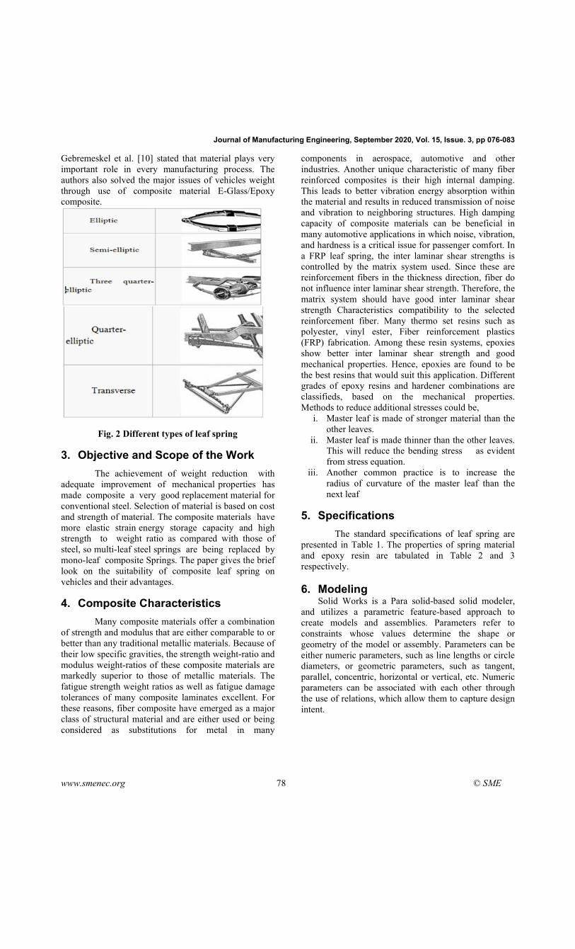
Gebremeskel et al. [10] stated that material plays very important role in every manufacturing process. The authors also solved the major issues of vehicles weight through use of composite material E-Glass/Epoxy composite.
Fig. 2 Different types of leaf spring
3. Objective and Scope of the Work
The achievement of weight reduction with adequate improvement of mechanical properties has made composite a very good replacement material for conventional steel. Selection of material is based on cost and strength of material. The composite materials have more elastic strain energy storage capacity and high strength to weight ratio as compared with those of steel, so multi-leaf steel springs are being replaced by mono-leaf composite Springs. The paper gives the brief look on the suitability of composite leaf spring on vehicles and their advantages.
4. Composite Characteristics
Many composite materials offer a combination of strength and modulus that are either comparable to or better than any traditional metallic materials. Because of their low specific gravities, the strength weight-ratio and modulus weight-ratios of these composite materials are markedly superior to those of metallic materials. The fatigue strength weight ratios as well as fatigue damage tolerances of many composite laminates excellent. For these reasons, fiber composite have emerged as a major class of structural material and are either used or being considered as substitutions for metal in many
components in aerospace, automotive and other industries. Another unique characteristic of many fiber reinforced composites is their high internal damping. This leads to better vibration energy absorption within the material and results in reduced transmission of noise and vibration to neighboring structures. High damping capacity of composite materials can be beneficial in many automotive applications in which noise, vibration, and hardness is a critical issue for passenger comfort. In a FRP leaf spring, the inter laminar shear strengths is controlled by the matrix system used. Since these are reinforcement fibers in the thickness direction, fiber do not influence inter laminar shear strength. Therefore, the matrix system should have good inter laminar shear strength Characteristics compatibility to the selected reinforcement fiber. Many thermo set resins such as polyester, vinyl ester, Fiber reinforcement plastics (FRP) fabrication. Among these resin systems, epoxies show better inter laminar shear strength and good mechanical properties. Hence, epoxies are found to be the best resins that would suit this application. Different grades of epoxy resins and hardener combinations are classifieds, based on the mechanical properties. Methods to reduce additional stresses could be,
i. Master leaf is made of stronger material than the other leaves.
ii. Master leaf is made thinner than the other leaves. This will reduce the bending stress as evident from stress equation.
iii. Another common practice is to increase the radius of curvature of the master leaf than the next leaf
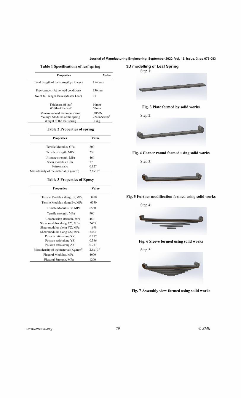
5. Specifications
The standard specifications of leaf spring are presented in Table 1. The properties of spring material and epoxy resin are tabulated in Table 2 and 3 respectively.
6. Modeling
Solid Works is a Para solid-based solid modeler, and utilizes a parametric feature-based approach to create models and assemblies. Parameters refer to constraints whose values determine the shape or geometry of the model or assembly. Parameters can be either numeric parameters, such as line lengths or circle diameters, or geometric parameters, such as tangent, parallel, concentric, horizontal or vertical, etc. Numeric parameters can be associated with each other through the use of relations, which allow them to capture design intent.
Journal of Manufacturing Engineering, September 2020, Vol. 15, Issue. 3, pp 076-083
www.smenec.org 79 © SME
Table 1 Specifications of leaf spring
Properties Value
Total Length of the spring(Eye to eye) 1540mm
Free camber (At no load condition) 136mm
No of full length leave (Master Leaf) 01
Thickness of leaf 10mm Width of the leaf 70mm
Maximum load given on spring 3850N Young's Modulus of the spring 22426N/mm2
Weight of the leaf spring 23kg
Table 2 Properties of spring
Properties Value
Tensile Modulus, GPa
Tensile strength, MPa
Ultimate strength, MPa
200
250
460 Shear modulus, GPa
Poisson ratio 77 0.127
Mass density of the material (Kg/mm3) 2.6x10⁻⁶
Table 3 Properties of Epoxy
Properties Value
Tensile Modulus along Ex, MPa
Tensile Modulus along Ey, MPa
Ultimate Modulus Ez, MPa
Tensile strength, MPa
Compressive strength, MPa
3400
6530
6530
900
450 Shear modulus along XY, MPa Shear modulus along YZ, MPa Shear modulus along ZX, MPa
Poisson ratio along XY Poisson ratio along YZ Poisson ratio along ZX
2433 1698 2433 0.217 0.366 0.217
Mass density of the material (Kg/mm3)
Flexural Modulus, MPa
Flexural Strength, MPa
2.6x10⁻⁶
4000
1200
3D modelling of Leaf Spring Step 1:
Fig. 3 Plate formed by solid works
Step 2:
Fig. 4 Corner round formed using solid works
Step 3:
Fig. 5 Further modification formed using solid works
Step 4:
Fig. 6 Sleeve formed using solid works
Step 5:
Fig. 7 Assembly view formed using solid works

Journal of Manufacturing Engineering, September 2020, Vol. 15, Issue. 3, pp 076-083
www.smenec.org 80 © SME
Step 6:
Fig. 8 Generated hole at the centre of leaf spring
The design stages of the composite leaf spring are sequentially provided in Figures. 3 to 8.
7. Analysis
The ANSYS Workbench platform is the framework upon which the industry's broadest and deepest suite of advanced engineering simulation technology is built. An innovative project schematic view ties together the entire simulation process, guiding the user through even complex multiphysics analyses with drag-and-drop simplicity. With bidirectional CAD connectivity, powerful highly-automated meshing, a project-level update mechanism, pervasive parameter management and integrated optimization tools, the ANSYS Workbench platform delivers unprecedented productivity, enabling Simulation-Driven Product development.
i. ANSYS Workbench is comprised of five modules: Simulation for performing structural and thermal analyses using the ANSYS solver.
ii. CFX-Mesh for generating a CFX-Pre mesh for the CFX-5 solver.
iii. Design Modeler for creating and modifying CAD geometry to prepare the solid model for use in Simulation or CFX-Mesh.
iv. DesignXplorer and DesignXplorer VT for investigating the effect of variations input to the response of the system.
v. FE Modeler for translating a Nastran mesh for use in ANSYS.
Step 1: Import the Solid works 3D model into ANSYS
Fig. 9 Structure of leaf spring
Step 2: Mesh preview of the design
Fig. 10 Meshing of Leaf spring
Step 3: Fixed Support
Fig. 11 Fixed support
Step 4: Load Application
Fig. 12 Loading condition
The imported leaf spring, meshed leaf spring, constraints provided, and loading conditions provided for the analysis are presented in Figures 9, 10, 11, and 12 respectively.
7.1 Stress Analysis The Finite Element Analysis (FEA) results for
the strain, stress and deformation for steel spring are presented in Figs. 13 to 15 respectively.

Journal of Manufacturing Engineering, September 2020, Vol. 15, Issue. 3, pp 076-083
www.smenec.org 81 © SME
Fig. 13 Strain analysis for steel material
Fig. 14 Stress analysis for steel material
Fig. 15 Deformation analysis for steel material
The FEA results for the deformation, stain and stress for epoxy spring are presented in Figs. 16 to 18 respectively.
Fig. 16 Deformation analysis for Epoxy material
Fig. 17 Strain analysis for Epoxy material
Fig. 18 Stress analysis for Epoxy material
8. Results and Discussion
Strzat and Paszeket [11] performed a three-dimensional contact analysis of the car leaf spring by considering static three-dimensional contact problem of the leaf car spring. The static characteristics of the car spring obtained for different models are compared with experimental investigations. Venkateshet et al. [12] described about the development of porous Aluminium foam for making commercial vehicle leaf spring made of Aluminium. The Aluminium foamed leaf spring has stresses much lower than steel leaf spring and weight of aluminium foamed leaf spring was reduced up to 20%. Harinathgowd & Evenugopalgoud et al. [13] performed static analysis on leaf spring by using ANSYS software and it is concluded that for the given specifications of the leaf spring, the maximum safe load is 7700N. It is observed that the maximum stress is developed at the inner side of the eye sections. In this work we applied same load on two materials like steel and epoxy. After applying load results came out from materials are showed in table.4. Epoxy resulted less mass compared to steel as shown in fig.19. In this work one of our main is weight reduction, so due to less weight we got better properties in epoxy.
Strength is the important property in leaf springs because depending upon the load leaf spring can withstand, so epoxy resulted a dramatic strength than the steel, nearly epoxy resulted double strength than steel showed in fig 20. Similarly, epoxy showed higher factor of safety than steel because its less weight and high strength showed in fig.21. Fig. 22 shows mass,

Journal of Manufacturing Engineering, September 2020, Vol. 15, Issue. 3, pp 076-083
www.smenec.org 82 © SME
strength and factor safety between steel and epoxy. From the results weight percentage was decreased, strength and factor of safety was increased in epoxy than steel.
Table 4 Parameters of Materials
Parameters Steel Epoxy
Load, KN
Deformation, mm
Strain
20
0.1
0.0009
20
1.4
0.019 Von-Misses stress, MPa
Yield strength, MPa 148 250
167 900
Factor of safety
Mass (kg)
1.69
4.27
5.38
1.41
Fig. 19 Comparison of mass of materials
Fig. 20 Comparison of strength of materials
Fig. 21 Comparison of Factor of safety of materials
Fig. 22 Comparison of Mass, Factor of Safety and strength
9. Conclusions
The strength of the spring made up of epoxy was found to be higher in comparison with that of spring made up of steel material, as epoxy is an orthotropic material. Therefore, Factor of Safety (FOS) needs to be very high while using epoxy material. At the same time, the mass density of epoxy was significantly less compared to steel. The added advantage of using epoxy spring is that the weight will be lesser; in turn, strength-to-weight ratio will be higher.

Journal of Manufacturing Engineering, September 2020, Vol. 15, Issue. 3, pp 076-083
www.smenec.org 83 © SME
REFERENCES 1. Vinkel Arora et al (2011), Eye design analysis of single
leaf spring in automotive vehicles using CAE tools. International Journal of Applied Engineering and Technology, 1(1): 88-97.
2. K. K. Jadhao and R. S. Dalu (2011), Experimental investigation & numerical analysis of composite leaf spring. International Journal of Engineering Science and Technology, 3(6):4759-4764.
3. M. M. Patunkar and D. R. Dolas (2011), Modelling and Analysis of Composite Leaf Spring under the Static Load Condition by using FEA. International Journal of Mechanical & Industrial Engineering, 1(1):1-4.
4. Sorathiya Mehul et al (2012), Analysis of composite leaf spring using FEA for light vehicle mini truck. Journal of Information, Knowledge and Research in Mechanical engineering, 2(2):424-428.
5. D.N.Dubey, S.G.Mahakalkar (2013), Stress Analysis of a Mono-parabolic Leaf Spring–A Review. IJMER, 3(2):769-772.
6. AnandKumar A. Satpute, Prof. S.S Chavan (2013), Mono Composite Leaf Spring – Design and Testing. Indian Journal of Applied Research, 3(7):282-285
7. Malaga. Anil Kumar, T.N.Charyulu, Ch.Ramesh (2012), Design Optimization of Leaf Spring, IJERA, 2(6):759-765
8. SenthilkumarMouleeswaran (2012). Design, Manufacturing and Testing of Polymer Composite Multi-Leaf Spring for Light Passenger Automobiles - A Review. www.intechopen.com.
9. R.B Charde, Dr.D.V. Bhope (2012), Investigation of stresses in master leaf of leaf spring by FEM and its experimental verification. IJEST, 4(2):20-27
10. Shishay Amare Gebremeskel (2012), Design, simulations, and prototyping of single composite Leaf Spring for Light Weight Vehicles. Global Journal of Researches in Engineering Mechanical and Mechanics Engineering, 12(7):21-30
11. A Skrtz, T.Paszek (2003), Three dimensional contact analysis of the car leaf spring”, Numerical methods in continuum mechanics, 7(4):115-124
12. S. Venkatesh, Dr. S. S. Mohamed Nazirudeen, Dr. A. K. Shaik Dawood, R. Karthikeyan (2012), IRACST – Engineering Science and Technology: An International Journal (ESTIJ), 2(4)
13. G. HarinathGowd& E Venugopal Goud (2012), Static Analysis of Leaf Spring” International Journal of Engineering Science and Technology (IJEST),4(8):3794-3804