Desiccant wheel regenerated by thermal energy from a microcogenerator: Experimental assessment of...
12
Desiccant wheel regenerated by thermal energy from a microcogenerator: Experimental assessment of the performances Giovanni Angrisani a , Alfonso Capozzoli b , Francesco Minichiello c,⇑ , Carlo Roselli a , Maurizio Sasso a a DING, Università degli Studi del Sannio, Piazza Roma 21, 82100 Benevento, Italy b TEBE Research Group, DENER, Politecnico di Torino, Corso Duca degli Abruzzi 24, 10129 Torino, Italy c DETEC, Università di Napoli Federico II, P.le Tecchio 80, 80125 Napoli, Italy article info Article history: Received 19 April 2010 Received in revised form 25 August 2010 Accepted 26 September 2010 Available online 29 October 2010 Keywords: Desiccant wheel HVAC system MCHP Experimental analysis Latent loads Regeneration temperature abstract Hybrid desiccant HVAC systems have shown several advantages, compared to conventional cooling and dehumidification systems. Therefore, their use is also spreading for tertiary and residential buildings, especially when the regeneration of the desiccant can be obtained by using available waste heat. In this paper, an experimental analysis is presented on the performances of a silica-gel desiccant wheel, inserted in a test facility characterized by an advanced desiccant air handling unit, coupled to an electric chiller, a natural gas-fired boiler and a small scale cogenerator. The desiccant wheel is regenerated by using low temperature thermal energy recovered from the microcogenerator. The effects of the main thermal-hygrometric parameters (outdoor air humidity ratio and temperature, regeneration air temperature) on the desiccant wheel performances have been experimentally evaluated; in particular, the thermal-hygrometric properties of the process air exiting the rotor and the desiccant wheel effectiveness values have been obtained. Finally, fixing the regeneration temperature at its maxi- mum available value (65 °C), ventilation and internal latent loads that the desiccant wheel can handle have been evaluated and compared to the required values, both for a set of cities all over the world and as a function of the thermal-hygrometric outdoor conditions. Ó 2010 Elsevier Ltd. All rights reserved. 1. Introduction Desiccant cooling is based on air dehumidification by means of a desiccant substance (solid or liquid), and on its subsequent cool- ing. In fact, the dehumidification process is exothermic and deter- mines a sensible heating of the airflow being dehumidified, which in turn has to be cooled to the thermal-hygrometric conditions necessary to handle the thermal loads [1–3]. To obtain a continuous operation of such a system, the desic- cant material has to be periodically regenerated by means of a hot airflow, in order to evaporate the absorbed/adsorbed water va- pour. Regeneration temperature depends on the desiccant mate- rial, but it can be low enough for the last generation of desiccants (60–70 °C is often sufficient), thus allowing the use of waste heat from cogeneration devices or energy recovered from a solar collector. Therefore, a desiccant cooling system comprises three main ele- ments (Fig. 1): the dehumidifier, the regeneration thermal energy source and the cooling device. As regards the dehumidifier, one of the most common configu- rations is the desiccant wheel (DW) that is a rotor filled with a solid desiccant material, which slowly rotates between the process air to be dehumidified and the regeneration air [4]. With reference to the thermal energy source for regeneration, the desiccant wheel can obviously be regenerated by a gas-fired boiler or an electric resistance when waste heat is either not avail- able or not sufficient (in terms of power or temperature); this oc- curs in particular for high regeneration temperature (above 80 °C). As regards the cooling device, it can be a direct or indirect evap- orative cooler, an air-to-air heat pump (in cooling mode), or an air- cooled water chiller. The obtained air conditioning system can be called desiccant- based (or hybrid) heating, ventilation and air conditioning (HVAC) system. Desiccant HVAC systems have the following main advantages compared to conventional cooling-based dehumidification systems [5,6]: (1) they can separately control sensible and latent load; (2) the cooling machine only has to cool the process air (without dehumidifying it), so it can operate with a higher chilled water temperature compared to a cooling machine coupled to a conventional cooling and dehumidification system, 0306-2619/$ - see front matter Ó 2010 Elsevier Ltd. All rights reserved. doi:10.1016/j.apenergy.2010.09.025 ⇑ Corresponding author. Tel.: +39 081 2538665; fax: +39 081 2390364. E-mail addresses: [email protected] (G. Angrisani), alfonso.capoz- [email protected] (A. Capozzoli), [email protected] (F. Minichiello), carlo.roselli@ unisannio.it (C. Roselli), [email protected] (M. Sasso). Applied Energy 88 (2011) 1354–1365 Contents lists available at ScienceDirect Applied Energy journal homepage: www.elsevier.com/locate/apenergy
-
Upload
independent -
Category
Documents
-
view
2 -
download
0
Transcript of Desiccant wheel regenerated by thermal energy from a microcogenerator: Experimental assessment of...
Applied Energy 88 (2011) 1354–1365
Contents lists available at ScienceDirect
Applied Energy
journal homepage: www.elsevier .com/ locate/apenergy
Desiccant wheel regenerated by thermal energy from a microcogenerator:Experimental assessment of the performances
Giovanni Angrisani a, Alfonso Capozzoli b, Francesco Minichiello c,⇑, Carlo Roselli a, Maurizio Sasso a
a DING, Università degli Studi del Sannio, Piazza Roma 21, 82100 Benevento, Italyb TEBE Research Group, DENER, Politecnico di Torino, Corso Duca degli Abruzzi 24, 10129 Torino, Italyc DETEC, Università di Napoli Federico II, P.le Tecchio 80, 80125 Napoli, Italy
a r t i c l e i n f o a b s t r a c t
Article history:Received 19 April 2010Received in revised form 25 August 2010Accepted 26 September 2010Available online 29 October 2010
Keywords:Desiccant wheelHVAC systemMCHPExperimental analysisLatent loadsRegeneration temperature
0306-2619/$ - see front matter � 2010 Elsevier Ltd. Adoi:10.1016/j.apenergy.2010.09.025
⇑ Corresponding author. Tel.: +39 081 2538665; faxE-mail addresses: [email protected]
[email protected] (A. Capozzoli), [email protected] (Funisannio.it (C. Roselli), [email protected] (M. Sasso
Hybrid desiccant HVAC systems have shown several advantages, compared to conventional cooling anddehumidification systems. Therefore, their use is also spreading for tertiary and residential buildings,especially when the regeneration of the desiccant can be obtained by using available waste heat.
In this paper, an experimental analysis is presented on the performances of a silica-gel desiccant wheel,inserted in a test facility characterized by an advanced desiccant air handling unit, coupled to an electricchiller, a natural gas-fired boiler and a small scale cogenerator. The desiccant wheel is regenerated byusing low temperature thermal energy recovered from the microcogenerator.
The effects of the main thermal-hygrometric parameters (outdoor air humidity ratio and temperature,regeneration air temperature) on the desiccant wheel performances have been experimentally evaluated;in particular, the thermal-hygrometric properties of the process air exiting the rotor and the desiccantwheel effectiveness values have been obtained. Finally, fixing the regeneration temperature at its maxi-mum available value (65 �C), ventilation and internal latent loads that the desiccant wheel can handlehave been evaluated and compared to the required values, both for a set of cities all over the worldand as a function of the thermal-hygrometric outdoor conditions.
� 2010 Elsevier Ltd. All rights reserved.
1. Introduction
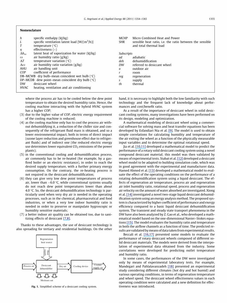
Desiccant cooling is based on air dehumidification by means ofa desiccant substance (solid or liquid), and on its subsequent cool-ing. In fact, the dehumidification process is exothermic and deter-mines a sensible heating of the airflow being dehumidified, whichin turn has to be cooled to the thermal-hygrometric conditionsnecessary to handle the thermal loads [1–3].
To obtain a continuous operation of such a system, the desic-cant material has to be periodically regenerated by means of ahot airflow, in order to evaporate the absorbed/adsorbed water va-pour. Regeneration temperature depends on the desiccant mate-rial, but it can be low enough for the last generation ofdesiccants (60–70 �C is often sufficient), thus allowing the use ofwaste heat from cogeneration devices or energy recovered from asolar collector.
Therefore, a desiccant cooling system comprises three main ele-ments (Fig. 1): the dehumidifier, the regeneration thermal energysource and the cooling device.
ll rights reserved.
: +39 081 2390364.(G. Angrisani), alfonso.capoz-. Minichiello), carlo.roselli@).
As regards the dehumidifier, one of the most common configu-rations is the desiccant wheel (DW) that is a rotor filled with a soliddesiccant material, which slowly rotates between the process air tobe dehumidified and the regeneration air [4].
With reference to the thermal energy source for regeneration,the desiccant wheel can obviously be regenerated by a gas-firedboiler or an electric resistance when waste heat is either not avail-able or not sufficient (in terms of power or temperature); this oc-curs in particular for high regeneration temperature (above 80 �C).
As regards the cooling device, it can be a direct or indirect evap-orative cooler, an air-to-air heat pump (in cooling mode), or an air-cooled water chiller.
The obtained air conditioning system can be called desiccant-based (or hybrid) heating, ventilation and air conditioning (HVAC)system.
Desiccant HVAC systems have the following main advantagescompared to conventional cooling-based dehumidification systems[5,6]:
(1) they can separately control sensible and latent load;(2) the cooling machine only has to cool the process air (without
dehumidifying it), so it can operate with a higher chilledwater temperature compared to a cooling machine coupledto a conventional cooling and dehumidification system,
Nomenclature
h specific enthalpy (kJ/kg)L specific ventilation latent load [W/(m3/h)]T temperature (�C)g effectiveness (–)Dhvs latent heat of vaporization for water (kJ/kg)x air humidity ratio (g/kg)DT temperature variation (�C)Dx air humidity ratio variation (g/kg)AHU air handling unitCOP coefficient of performanceDB–MCWB dry bulb–mean coincident wet bulb (�C)DP–MCDB dew point–mean coincident dry bulb (�C)DW desiccant wheelHVAC heating, ventilation and air conditioning
MCHP Micro Combined Heat and PowerSHR sensible heat ratio, i.e. the ratio between the sensible
and total thermal load
Subscriptsad adiabaticdeh dehumidificationDW referred to desiccant wheelo outdoor airr roomreg regenerations supplyth thermal
G. Angrisani et al. / Applied Energy 88 (2011) 1354–1365 1355
where the process air has to be cooled below the dew pointtemperature to obtain the desired humidity ratio. Hence, thecooling machine interacting with the hybrid HVAC systemhas a higher COP;
(3) due to the higher value of COP, electric energy requirementof the cooling machine is reduced;
(4) as the cooling machine only has to cool the process air with-out dehumidifying it, a reduction of the chiller size and con-sequently of the refrigerant fluid mass is obtained, and so alower environmental impact, both in terms of direct impact(ozone layer reduction and greenhouse effect due to refriger-ant fluids) and of indirect one (the reduced electric energyuse determines lower equivalent CO2 emissions of the powerplants);
(5) in the conventional cooling and dehumidification process,air commonly has to be re-heated (for example, by a gas-fired boiler or an electric resistance), in order to reach thedesired supply temperature, with a further primary energyconsumption. On the contrary, the re-heating process isnot required in the desiccant dehumidification;
(6) they can give very low dew point temperatures of processair, lower than �6.0 �C, while conventional systems usuallydo not reach dew point temperatures lower than about4.0 �C. So, the desiccant dehumidification technology is par-ticularly used when very dry air is needed in the operatingprocesses, such as in the chemical, pharmaceutical and foodindustries, or when a very low indoor humidity ratio isneeded in order to preserve or manipulate hygroscopic orhumidity sensitive materials;
(7) a better indoor air quality can be obtained too, due to sani-tizing effects of desiccant [7,8].
Thanks to these advantages, the use of desiccant technology isalso spreading for tertiary and residential buildings. On the other
Cooling device Dry air Desiccant dehumidifier
Regeneration heat source
Process air
Moisture out
Cooled supply air
Heat
supply
Fig. 1. Simplified scheme of a desiccant cooling system.
hand, it is necessary to highlight both the low familiarity with suchtechnology and the frequent lack of knowledge about perfor-mances and cost/benefit ratio.
As a result of the importance of desiccant wheel in solid desic-cant cooling systems, many investigations have been performed onits design, modeling and optimization.
A mathematical modeling of desiccant wheel using a commer-cial software for solving mass and heat transfer equations has beendeveloped by Esfandiari Nia et al. [9]. The model is used to obtainsimple correlations for calculating humidity and temperature ofthe air exiting the wheel as a function of the physically measurableinput variables and to determine the optimal rotational speed.
Jia et al. [10,11] developed a mathematical model to predict theperformance of a rotary solid desiccant cooling system using a novelcompound desiccant material; this model was then validated bymeans of experimental tests. Stabat et al. [12] developed a desiccantwheel model to be adapted to building simulation code, which wasin good agreement with the experimental and manufacturer data.Hamed Ahmed et al. [13] developed a mathematical model to eval-uate the effect of the operating conditions on the performance of arotating dehumidification system using a liquid desiccant. The ef-fects of regeneration air temperature, process air and regenerationair inlet humidity ratio, rotational speed, process and regenerationair velocity on the amount of water absorbed are investigated. Xionget al. [14] investigated a novel two-stage liquid desiccant dehumid-ification system using an exergy analysis method. The proposed sys-tem is characterized by higher coefficient of performance and exergyefficiency compared to a basic liquid desiccant dehumidificationsystem. The transient and steady state transport phenomena in theDW have also been analyzed by Z. Gao et al., who developed a math-ematical model based on the one-dimensional Navier–Stokes equa-tions [15]. The model evaluates the humidity ratio and temperaturein both the airflow channels as a function of time. The predicted re-sults are validated by means of data taken from experimental results.
Beccali et al. [16,17] presented some models to evaluate theperformance of rotary desiccant wheels composed of different so-lid desiccant materials. The models were derived from the interpo-lation of experimental data obtained from the industry. Somecorrelations were developed for predicting outlet temperatureand humidity ratio.
In some cases, the performances of the DW were investigatedonly by means of experimental laboratory tests. For example,Mandegari and Pahlalavanzadeh [18] presented an experimentalstudy considering different climates (hot dry and hot humid) andvarious operating conditions, in terms of regeneration temperatureand wheel speed. The desiccant wheel effectiveness values in eachoperating condition were calculated and a new definition for effec-tiveness was introduced.
1356 G. Angrisani et al. / Applied Energy 88 (2011) 1354–1365
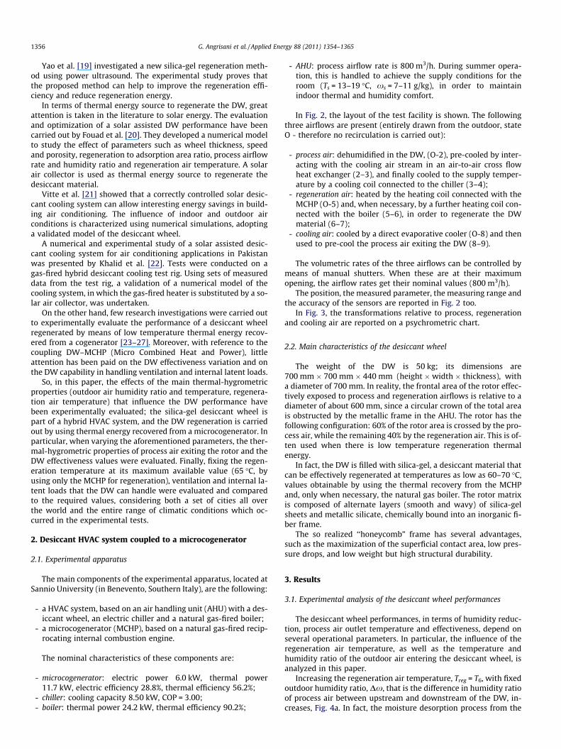
Yao et al. [19] investigated a new silica-gel regeneration meth-od using power ultrasound. The experimental study proves thatthe proposed method can help to improve the regeneration effi-ciency and reduce regeneration energy.
In terms of thermal energy source to regenerate the DW, greatattention is taken in the literature to solar energy. The evaluationand optimization of a solar assisted DW performance have beencarried out by Fouad et al. [20]. They developed a numerical modelto study the effect of parameters such as wheel thickness, speedand porosity, regeneration to adsorption area ratio, process airflowrate and humidity ratio and regeneration air temperature. A solarair collector is used as thermal energy source to regenerate thedesiccant material.
Vitte et al. [21] showed that a correctly controlled solar desic-cant cooling system can allow interesting energy savings in build-ing air conditioning. The influence of indoor and outdoor airconditions is characterized using numerical simulations, adoptinga validated model of the desiccant wheel.
A numerical and experimental study of a solar assisted desic-cant cooling system for air conditioning applications in Pakistanwas presented by Khalid et al. [22]. Tests were conducted on agas-fired hybrid desiccant cooling test rig. Using sets of measureddata from the test rig, a validation of a numerical model of thecooling system, in which the gas-fired heater is substituted by a so-lar air collector, was undertaken.
On the other hand, few research investigations were carried outto experimentally evaluate the performance of a desiccant wheelregenerated by means of low temperature thermal energy recov-ered from a cogenerator [23–27]. Moreover, with reference to thecoupling DW–MCHP (Micro Combined Heat and Power), littleattention has been paid on the DW effectiveness variation and onthe DW capability in handling ventilation and internal latent loads.
So, in this paper, the effects of the main thermal-hygrometricproperties (outdoor air humidity ratio and temperature, regenera-tion air temperature) that influence the DW performance havebeen experimentally evaluated; the silica-gel desiccant wheel ispart of a hybrid HVAC system, and the DW regeneration is carriedout by using thermal energy recovered from a microcogenerator. Inparticular, when varying the aforementioned parameters, the ther-mal-hygrometric properties of process air exiting the rotor and theDW effectiveness values were evaluated. Finally, fixing the regen-eration temperature at its maximum available value (65 �C, byusing only the MCHP for regeneration), ventilation and internal la-tent loads that the DW can handle were evaluated and comparedto the required values, considering both a set of cities all overthe world and the entire range of climatic conditions which oc-curred in the experimental tests.
2. Desiccant HVAC system coupled to a microcogenerator
2.1. Experimental apparatus
The main components of the experimental apparatus, located atSannio University (in Benevento, Southern Italy), are the following:
- a HVAC system, based on an air handling unit (AHU) with a des-iccant wheel, an electric chiller and a natural gas-fired boiler;
- a microcogenerator (MCHP), based on a natural gas-fired recip-rocating internal combustion engine.
The nominal characteristics of these components are:
- microcogenerator: electric power 6.0 kW, thermal power11.7 kW, electric efficiency 28.8%, thermal efficiency 56.2%;
- chiller: cooling capacity 8.50 kW, COP = 3.00;- boiler: thermal power 24.2 kW, thermal efficiency 90.2%;
- AHU: process airflow rate is 800 m3/h. During summer opera-tion, this is handled to achieve the supply conditions for theroom (Ts = 13–19 �C, xs = 7–11 g/kg), in order to maintainindoor thermal and humidity comfort.
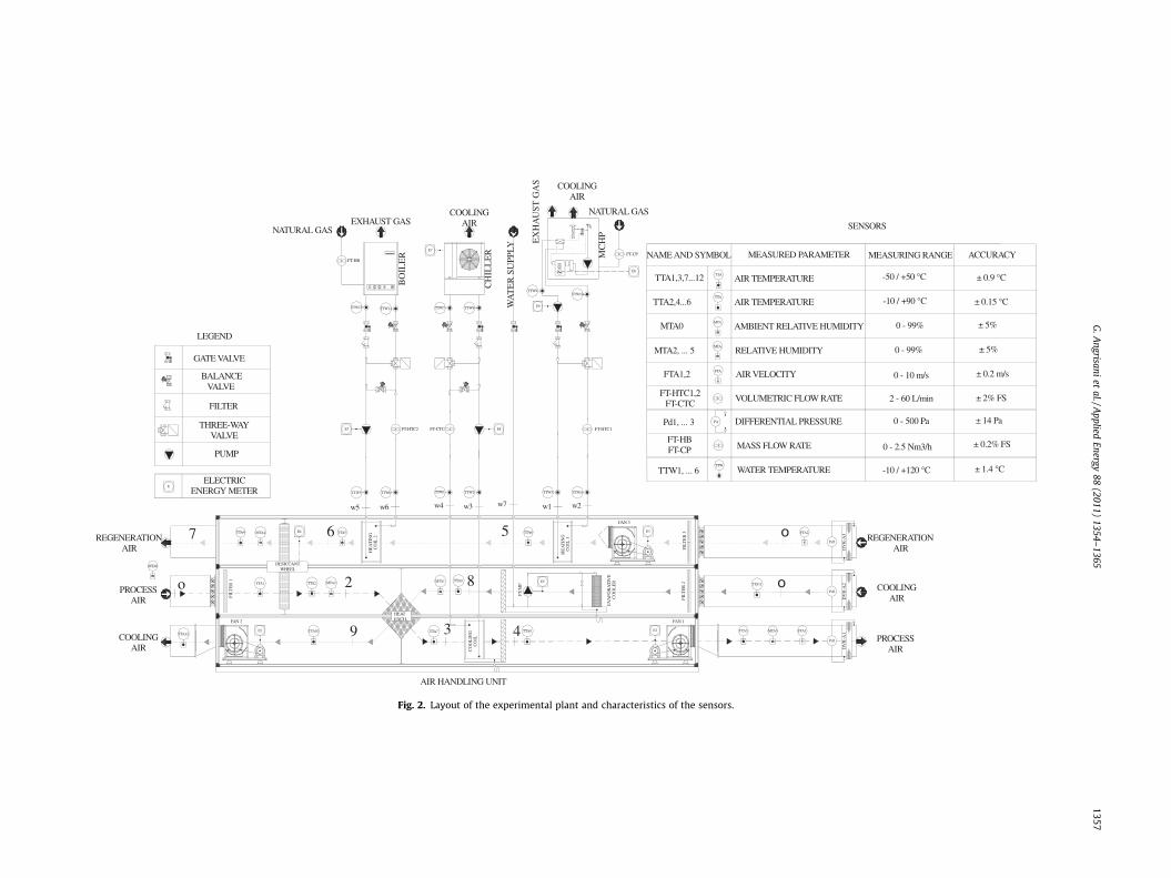
In Fig. 2, the layout of the test facility is shown. The followingthree airflows are present (entirely drawn from the outdoor, stateO - therefore no recirculation is carried out):
- process air: dehumidified in the DW, (O-2), pre-cooled by inter-acting with the cooling air stream in an air-to-air cross flowheat exchanger (2–3), and finally cooled to the supply temper-ature by a cooling coil connected to the chiller (3–4);
- regeneration air: heated by the heating coil connected with theMCHP (O-5) and, when necessary, by a further heating coil con-nected with the boiler (5–6), in order to regenerate the DWmaterial (6–7);
- cooling air: cooled by a direct evaporative cooler (O-8) and thenused to pre-cool the process air exiting the DW (8–9).
The volumetric rates of the three airflows can be controlled bymeans of manual shutters. When these are at their maximumopening, the airflow rates get their nominal values (800 m3/h).
The position, the measured parameter, the measuring range andthe accuracy of the sensors are reported in Fig. 2 too.
In Fig. 3, the transformations relative to process, regenerationand cooling air are reported on a psychrometric chart.
2.2. Main characteristics of the desiccant wheel
The weight of the DW is 50 kg; its dimensions are700 mm � 700 mm � 440 mm (height �width � thickness), witha diameter of 700 mm. In reality, the frontal area of the rotor effec-tively exposed to process and regeneration airflows is relative to adiameter of about 600 mm, since a circular crown of the total areais obstructed by the metallic frame in the AHU. The rotor has thefollowing configuration: 60% of the rotor area is crossed by the pro-cess air, while the remaining 40% by the regeneration air. This is of-ten used when there is low temperature regeneration thermalenergy.
In fact, the DW is filled with silica-gel, a desiccant material thatcan be effectively regenerated at temperatures as low as 60–70 �C,values obtainable by using the thermal recovery from the MCHPand, only when necessary, the natural gas boiler. The rotor matrixis composed of alternate layers (smooth and wavy) of silica-gelsheets and metallic silicate, chemically bound into an inorganic fi-ber frame.
The so realized ‘‘honeycomb” frame has several advantages,such as the maximization of the superficial contact area, low pres-sure drops, and low weight but high structural durability.
3. Results
3.1. Experimental analysis of the desiccant wheel performances
The desiccant wheel performances, in terms of humidity reduc-tion, process air outlet temperature and effectiveness, depend onseveral operational parameters. In particular, the influence of theregeneration air temperature, as well as the temperature andhumidity ratio of the outdoor air entering the desiccant wheel, isanalyzed in this paper.
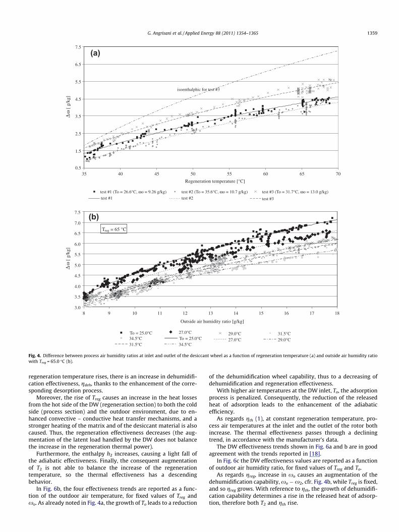
Increasing the regeneration air temperature, Treg = T6, with fixedoutdoor humidity ratio, Dx, that is the difference in humidity ratioof process air between upstream and downstream of the DW, in-creases, Fig. 4a. In fact, the moisture desorption process from the
TTA7
FAN 2
E2
E4
FT-HTC2
TTW5 TTW6
FAN 1
TTA8 E1
DV
R-A
1
Pd1
TTW1 TTW2
FT-CTC
TTA6
FT-HTC1
TTW3 TTW4
E3
FAN 3
Pd2
DV
R-A
2D
VR
-A3
Pd3
TTA5
MTA2TTA2TTA1
MTA0
TTA4 MTA4
TTA3 MTA3
NATURAL GAS
NATURAL GASEXHAUST GAS
EX
HA
UST
GA
S
FT-HB
BO
ILE
R
CH
ILL
ER FT-CPM
CH
P
E7
FTA1
FTA2
E5
WA
TE
R S
UPP
LY
TTA1,3,7...12
MTA2, ... 5
TTW1, ... 6 WATER TEMPERATURE
AIR TEMPERATURE
FTA1,2 AIR VELOCITY
0 - 2.5 Nm3/h
-50 / +50 °C
MTA0 AMBIENT RELATIVE HUMIDITY
RELATIVE HUMIDITY
VOLUMETRIC FLOW RATE
Pd1, ... 3 DIFFERENTIAL PRESSURE
MASS FLOW RATE
E6
PU
MP
MTA1
DESICCANTWHEEL
FIL
TE
R 1
FIL
TE
R 2
HEATEXCH.
FIL
TE
R 3
CO
OL
ING
CO
IL
HE
AT
ING
CO
IL 1
HE
AT
ING
CO
IL 2
E8E7
AIR HANDLING UNIT
REGENERATIONAIR
PROCESSAIR
COOLINGAIR
REGENERATIONAIR
o 2
3 4
o567
o8
9
w1 w2w5 w6 w3w4 w7
COOLINGAIR
COOLINGAIR
TTA
TTW
MTA
MTA
FTA
Pd
E
GATE VALVE
BALANCEVALVE
FILTER
SENSORS
LEGEND
THREE-WAYVALVE
PUMP
E9
EV
AP
OR
AT
IVE
CO
OL
ER
PROCESSAIR
FT-HTC1,2FT-CTC
FT-HBFT-CP
COOLINGAIR
NAME AND SYMBOL MEASURED PARAMETER MEASURING RANGE ACCURACY
± 0.9 °C
TTA
TTA2,4...6 AIR TEMPERATURE -10 / +90 °C
0 - 99% ± 5%
0 - 99% ± 5%
0 - 10 m/s ± 0.2 m/s
2 - 60 L/min ± 2% FS
± 0.2% FS
0 - 500 Pa ± 14 Pa
-10 / +120 °C ± 1.4 °C
TTA9
TTA10TTA12
TTA11
± 0.15 °CTTW8TTW7TTW12 TTW11
TTW9TTW10
ELECTRICENERGY METER
Fig. 2. Layout of the experimental plant and characteristics of the sensors.
G.A
ngrisaniet
al./Applied
Energy88
(2011)1354–
13651357
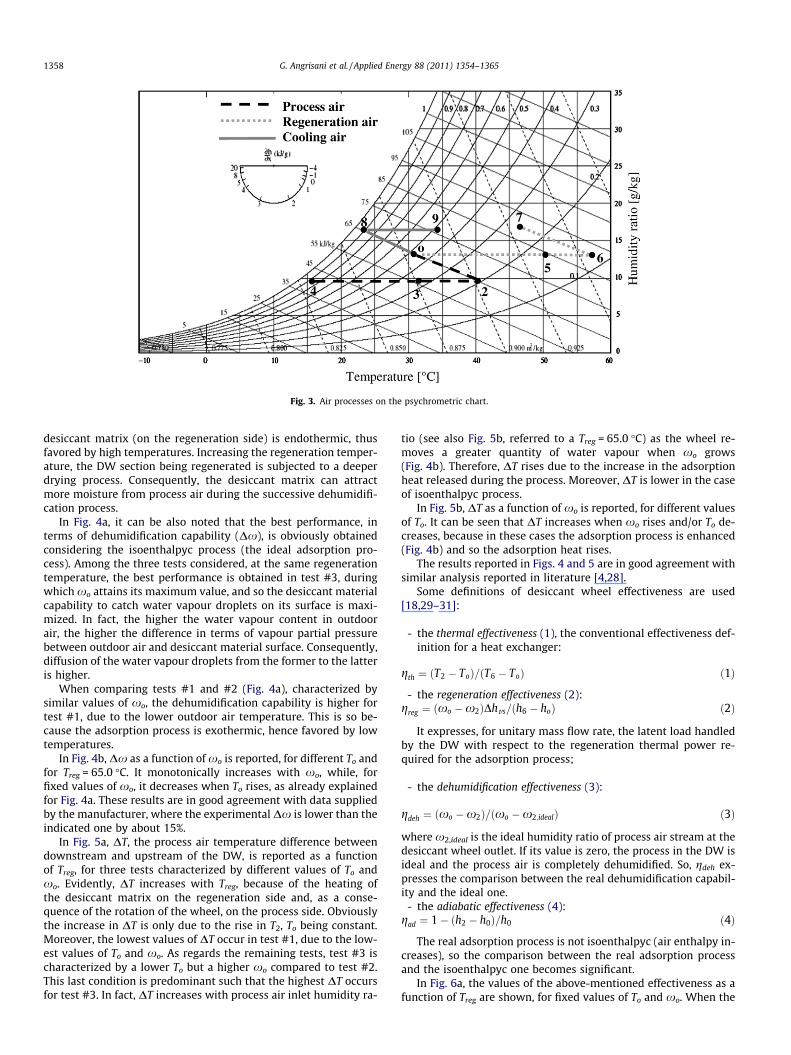
Fig. 3. Air processes on the psychrometric chart.
1358 G. Angrisani et al. / Applied Energy 88 (2011) 1354–1365
desiccant matrix (on the regeneration side) is endothermic, thusfavored by high temperatures. Increasing the regeneration temper-ature, the DW section being regenerated is subjected to a deeperdrying process. Consequently, the desiccant matrix can attractmore moisture from process air during the successive dehumidifi-cation process.
In Fig. 4a, it can be also noted that the best performance, interms of dehumidification capability (Dx), is obviously obtainedconsidering the isoenthalpyc process (the ideal adsorption pro-cess). Among the three tests considered, at the same regenerationtemperature, the best performance is obtained in test #3, duringwhich xo attains its maximum value, and so the desiccant materialcapability to catch water vapour droplets on its surface is maxi-mized. In fact, the higher the water vapour content in outdoorair, the higher the difference in terms of vapour partial pressurebetween outdoor air and desiccant material surface. Consequently,diffusion of the water vapour droplets from the former to the latteris higher.
When comparing tests #1 and #2 (Fig. 4a), characterized bysimilar values of xo, the dehumidification capability is higher fortest #1, due to the lower outdoor air temperature. This is so be-cause the adsorption process is exothermic, hence favored by lowtemperatures.
In Fig. 4b, Dx as a function of xo is reported, for different To andfor Treg = 65.0 �C. It monotonically increases with xo, while, forfixed values of xo, it decreases when To rises, as already explainedfor Fig. 4a. These results are in good agreement with data suppliedby the manufacturer, where the experimental Dx is lower than theindicated one by about 15%.
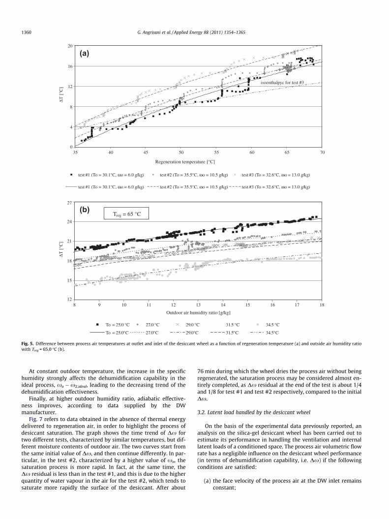
In Fig. 5a, DT, the process air temperature difference betweendownstream and upstream of the DW, is reported as a functionof Treg, for three tests characterized by different values of To andxo. Evidently, DT increases with Treg, because of the heating ofthe desiccant matrix on the regeneration side and, as a conse-quence of the rotation of the wheel, on the process side. Obviouslythe increase in DT is only due to the rise in T2, To being constant.Moreover, the lowest values of DT occur in test #1, due to the low-est values of To and xo. As regards the remaining tests, test #3 ischaracterized by a lower To but a higher xo compared to test #2.This last condition is predominant such that the highest DT occursfor test #3. In fact, DT increases with process air inlet humidity ra-
tio (see also Fig. 5b, referred to a Treg = 65.0 �C) as the wheel re-moves a greater quantity of water vapour when xo grows(Fig. 4b). Therefore, DT rises due to the increase in the adsorptionheat released during the process. Moreover, DT is lower in the caseof isoenthalpyc process.
In Fig. 5b, DT as a function of xo is reported, for different valuesof To. It can be seen that DT increases when xo rises and/or To de-creases, because in these cases the adsorption process is enhanced(Fig. 4b) and so the adsorption heat rises.
The results reported in Figs. 4 and 5 are in good agreement withsimilar analysis reported in literature [4,28].
Some definitions of desiccant wheel effectiveness are used[18,29–31]:
- the thermal effectiveness (1), the conventional effectiveness def-inition for a heat exchanger:
gth ¼ ðT2 � ToÞ=ðT6 � ToÞ ð1Þ
- the regeneration effectiveness (2):greg ¼ ðxo �x2ÞDhvs=ðh6 � hoÞ ð2Þ
It expresses, for unitary mass flow rate, the latent load handledby the DW with respect to the regeneration thermal power re-quired for the adsorption process;
- the dehumidification effectiveness (3):
gdeh ¼ ðxo �x2Þ=ðxo �x2;idealÞ ð3Þ
where x2,ideal is the ideal humidity ratio of process air stream at thedesiccant wheel outlet. If its value is zero, the process in the DW isideal and the process air is completely dehumidified. So, gdeh ex-presses the comparison between the real dehumidification capabil-ity and the ideal one.
- the adiabatic effectiveness (4):gad ¼ 1� ðh2 � h0Þ=h0 ð4Þ
The real adsorption process is not isoenthalpyc (air enthalpy in-creases), so the comparison between the real adsorption processand the isoenthalpyc one becomes significant.
In Fig. 6a, the values of the above-mentioned effectiveness as afunction of Treg are shown, for fixed values of To and xo. When the
0.5
1.5
2.5
3.5
4.5
5.5
6.5
7.5
35 40 45 50 55 60 65 70
Regeneration temperature [°C]
ω [
g/kg
]
test #1 (To = 26.6°C, ωo = 9.26 g/kg) test #2 (To = 35.6°C, ωo = 10.7 g/kg) test #3 (To = 31.7°C, ωo = 13.0 g/kg)
test #1 test #2 test #3
Δ
isoenthalphic for test #3
3.0
3.5
4.0
4.5
5.0
5.5
6.0
6.5
7.0
7.5
8 9 10 11 12 13 14 15 16 17 18
Outside air humidity ratio [g/kg]
To = 25.0°C 27.0°C 29.0°C 31.5°C34.5°C To = 25.0°C 27.0°C 29.0°C31.5°C 34.5°C
Treg = 65 °C
ω [
g/kg
]Δ
(a)
(b)
Fig. 4. Difference between process air humidity ratios at inlet and outlet of the desiccant wheel as a function of regeneration temperature (a) and outside air humidity ratiowith Treg = 65.0 �C (b).
G. Angrisani et al. / Applied Energy 88 (2011) 1354–1365 1359
regeneration temperature rises, there is an increase in dehumidifi-cation effectiveness, gdeh, thanks to the enhancement of the corre-sponding desorption process.
Moreover, the rise of Treg causes an increase in the heat lossesfrom the hot side of the DW (regeneration section) to both the coldside (process section) and the outdoor environment, due to en-hanced convective – conductive heat transfer mechanisms, and astronger heating of the matrix and of the desiccant material is alsocaused. Thus, the regeneration effectiveness decreases (the aug-mentation of the latent load handled by the DW does not balancethe increase in the regeneration thermal power).
Furthermore, the enthalpy h2 increases, causing a light fall ofthe adiabatic effectiveness. Finally, the consequent augmentationof T2 is not able to balance the increase of the regenerationtemperature, so the thermal effectiveness has a descendingbehavior.
In Fig. 6b, the four effectiveness trends are reported as a func-tion of the outdoor air temperature, for fixed values of Treg andxo. As already noted in Fig. 4a, the growth of To leads to a reduction
of the dehumidification wheel capability, thus to a decreasing ofdehumidification and regeneration effectiveness.
With higher air temperatures at the DW inlet, To, the adsorptionprocess is penalized. Consequently, the reduction of the releasedheat of adsorption leads to the enhancement of the adiabaticefficiency.
As regards gth (1), at constant regeneration temperature, pro-cess air temperatures at the inlet and the outlet of the rotor bothincrease. The thermal effectiveness passes through a decliningtrend, in accordance with the manufacturer’s data.
The DW effectiveness trends shown in Fig. 6a and b are in goodagreement with the trends reported in [18].
In Fig. 6c the DW effectiveness values are reported as a functionof outdoor air humidity ratio, for fixed values of Treg and To.
As regards greg, increase in xo causes an augmentation of thedehumidification capability, xo �x2, cfr. Fig. 4b, while Treg is fixed,and so greg grows. With reference to gth, the growth of dehumidifi-cation capability determines a rise in the released heat of adsorp-tion, therefore both T2 and gth rise.
0
4
8
12
16
20
35 40 45 50 55 60 65 70
Regeneration temperature [°C]
[°C
]
test #1 (To = 30.1°C, ωo = 6.0 g/kg) test #2 (To = 35.5°C, ωo = 10.5 g/kg) test #3 (To = 32.6°C, ωo = 13.0 g/kg)
test #1 (To = 30.1°C, ωo = 6.0 g/kg) test #2 (To = 35.5°C, ωo = 10.5 g/kg) test #3 (To = 32.6°C, ωo = 13.0 g/kg)
isoenthalpyc for test #3
12
15
18
21
24
27
8 9 10 11 12 13 14 15 16 17 18
Outdoor air humidity ratio [g/kg]
[°C
]
To = 25.0 °C 27.0 °C 29.0 °C 31.5 °C 34.5 °C
To = 25.0°C 27.0°C 29.0°C 31.5°C 34.5°C
Treg = 65 °C
(a)
(b)
Fig. 5. Difference between process air temperatures at outlet and inlet of the desiccant wheel as a function of regeneration temperature (a) and outside air humidity ratiowith Treg = 65.0 �C (b).
1360 G. Angrisani et al. / Applied Energy 88 (2011) 1354–1365
At constant outdoor temperature, the increase in the specifichumidity strongly affects the dehumidification capability in theideal process, xo �x2,ideal, leading to the decreasing trend of thedehumidification effectiveness.
Finally, at higher outdoor humidity ratio, adiabatic effective-ness improves, according to data supplied by the DWmanufacturer.
Fig. 7 refers to data obtained in the absence of thermal energydelivered to regeneration air, in order to highlight the process ofdesiccant saturation. The graph shows the time trend of Dx fortwo different tests, characterized by similar temperatures, but dif-ferent moisture contents of outdoor air. The two curves start fromthe same initial value of Dx, and then continue differently. In par-ticular, in the test #2, characterized by a higher value of xo, thesaturation process is more rapid. In fact, at the same time, theDx residual is less than in the test #1, and this is due to the higherquantity of water vapour in the air for the test #2, which tends tosaturate more rapidly the surface of the desiccant. After about
76 min during which the wheel dries the process air without beingregenerated, the saturation process may be considered almost en-tirely completed, as Dx residual at the end of the test is about 1/4and 1/8 for test #1 and test #2 respectively, compared to the initialDx.
3.2. Latent load handled by the desiccant wheel
On the basis of the experimental data previously reported, ananalysis on the silica-gel desiccant wheel has been carried out toestimate its performance in handling the ventilation and internallatent loads of a conditioned space. The process air volumetric flowrate has a negligible influence on the desiccant wheel performance(in terms of dehumidification capability, i.e. Dx) if the followingconditions are satisfied:
(a) the face velocity of the process air at the DW inlet remainsconstant;

10
20
30
40
50
60
70
80
90
100
45 50 55 60 65 70
Regeneration temperature [°C]
[%]
thermal
dehumidification
regeneration
adiabatic
ωo = 13.0 g/kg
To = 32.7°C
20
30
40
50
60
70
80
90
25 27 29 31 33 35
Process air inlet temperature [°C]
[%]
thermal
dehumidification
adiabatic
regeneration
ωo = 11.2 g/kg
Treg = 66.4°C
20
30
40
50
60
70
80
90
7 9 11 13 15
Process air inlet humidity ratio [g/kg]
[%]
thermal
adiabatic
dehumidification
regeneration
To = 31.6°C
Treg = 66.2°C
(a)
(b)
(c)
Fig. 6. Various types of desiccant wheel effectiveness as a function of regenerationtemperature (a), process air inlet temperature (b) and humidity ratio (c).
0.5
1.0
1.5
2.0
2.5
3.0
3.5
4.0
1 16 31
Time
ω [g
/kg]
Fig. 7. Difference between process air humidity ratios at inlet and outlet of the desicca
G. Angrisani et al. / Applied Energy 88 (2011) 1354–1365 1361
(b) the ratio between process air and regeneration air flow rateis equal to 1, as in the previously reported experimentalanalysis.
In this case, the DW dehumidification performance is substan-tially independent of volumetric flow rate. In the following analy-sis, the ventilation and internal latent loads are expressed perunitary volumetric air flow rate, considering indoor thermal-hygro-metric conditions characterized by Tr = 25 �C and xr = 10.5 g/kg(relative humidity = 54%), and supply air temperature equal to17 �C; Treg is fixed to 65 �C (maximum value obtainable by usingthe selected MCHP).
The outdoor design conditions herein considered are based onthe following ASHRAE data [32]:
- design for cooling: 0.4% DB–MCWB (dry bulb–mean coincidentwet bulb), 1.0% DB–MCWB and 2.0% DB–MCWB;
- design for dehumidification: 0.4% DP–MCDB (dew point–meancoincident dry bulb) and 1.0% DP–MCDB.
It is helpful to use an example for understanding these designdata. For Istanbul, 0.4% DB = 31.1 �C and MCWB = 21.4 �C: as re-gards DB temperature, this means that the value 31.1 �C is ex-ceeded on average by the indicated percentage (0.4%) of the totalnumber of hours in a year (8760), i.e. by 35 h per year, for the per-iod of record; as regards MCWB temperature, the value 21.4 �C de-fines the average wet bulb temperature that was observed whenthe air was at the extreme high dry bulb temperature (31.1 �C).In other words, the value 21.4 �C is not the average wet bulb tem-perature during the entire warm season, but just its average valuewhen the air is very hot [33].
The designer has to choose the set of conditions and probabilityof occurrence that can be conveniently applied to the specific situ-ation. The DB–MCWB data represent outdoor conditions of hot,mostly sunny days. They are therefore commonly used in sizingcooling equipment, such as chillers and cooling coils. On the con-trary, design conditions based on dew point temperatures (DP–MCDB) are directly related to the highest values of humidity ratio,which represent peak moisture loads from the weather. These val-ues are especially useful for humidity control applications, hencein desiccant cooling and dehumidification, cooling-based dehu-midification and ventilation system design.
46 61 76
[min]
test #1 (To = 26.7°C,ωo = 5.37 g/kg)
test #2 (To = 26.1°C, ωo = 7.56 g/kg)
test #1
test #2
nt wheel as a function of the time, in the absence of regeneration thermal energy.

(a)
(b)
0
1
2
3
4
5
Wie
n/C
ity
Ath
inai
Bud
apes
t/F
erih
egy
I
Beo
grad
Sar
ajev
o/B
utm
ir
Zag
reb/
Mak
sim
ir
Buc
ures
ti A
fum
ati
Bol
ogna
Fir
enze
Ista
nbul
Cas
abla
nca
Bos
ton
Ott
awa
Toro
nto
But
tonv
ille
A
Lim
a
Syd
ney
Air
port
Am
o
Spe
cifi
c ve
ntila
tion
lat
ent l
oad
ha
ndle
d b
y th
e D
W [
W/(
m3 /
h)]
0.4 % DB-MCWB 1.0 % DB-MCWB 2.0 % DB-MCWB
93%84% 90%
90%95%
90%91%
98%
2
3
4
5
6
Wie
n/C
ity
Ath
inai
Bud
apes
t/F
erih
egy
I
Beo
grad
Sar
ajev
o/B
utm
ir
Zag
reb/
Mak
sim
ir
Buc
ures
ti A
fum
ati
Bol
ogna
Fir
enze
Ista
nbul
Cas
abla
nca
Bos
ton
Ott
awa
Toro
nto
But
tonv
ille
A
Lim
a
Syd
ney
Air
port
Am
o
Spe
cifi
c ve
ntila
tion
lat
ent l
oad
ha
ndle
d b
y th
e D
W [
W/(
m3 /
h)]
0.4 % DP-MCDB 1.0 % DP-MCDB
Fig. 8. Specific ventilation latent load handled by the desiccant wheel for various cities and for different outdoor design thermal-hygrometric conditions (Treg = 65 �C).
1362 G. Angrisani et al. / Applied Energy 88 (2011) 1354–1365
In Fig. 8, the specific ventilation latent load that can be handledby the desiccant wheel for different cities around the world is re-ported. The cities selected for the analysis are characterized by val-ues of the outdoor humidity ratio (derived from DB–MCWB andDP–MCDB data) included within the range of experimental dataavailable for the desiccant wheel performance (see Section 3.1).
Fig. 8a refers to DB–MCWB data (for cooling purposes), whileFig. 8b refers to DP–MCDB data (for dehumidification purposes).For those cities where the DW is able to handle the entire requiredspecific ventilation latent load (L, proportional to xo �xr), it is re-ported on the ordinate. This occurs for all the cities in Fig. 8a andonly for some of them in Fig. 8b. On the contrary, for those citieswhere the DW cannot entirely balance L, only the fraction of L cov-ered by the DW (proportional to xo �xs, with xs experimentallyevaluated) is shown on the ordinate and reported in percentagetoo. This occurs for some cities (such as Athinai and Bologna) inFig. 8b. This result strictly depends on the above-mentioned differ-ence between DB–MCWB and DP–MCDB data. Moreover, note thatfor some cities and for certain percentiles (Athinai, Beograd, Sara-jievo, Sydney), the ordinate is equal to zero (Fig. 8a) because the in-door humidity ratio is higher than outdoor one (i.e., there is noventilation latent load).
As regards the experimental evaluation of xs (the supply airhumidity ratio, equal to the process air humidity ratio after the
desiccant wheel), it is obtained for each city by the experimentalknowledge of the maximum desiccant wheel dehumidificationcapability (DxDW) relative to a regeneration temperature of65 �C, i.e. xs = xo � DxDW.
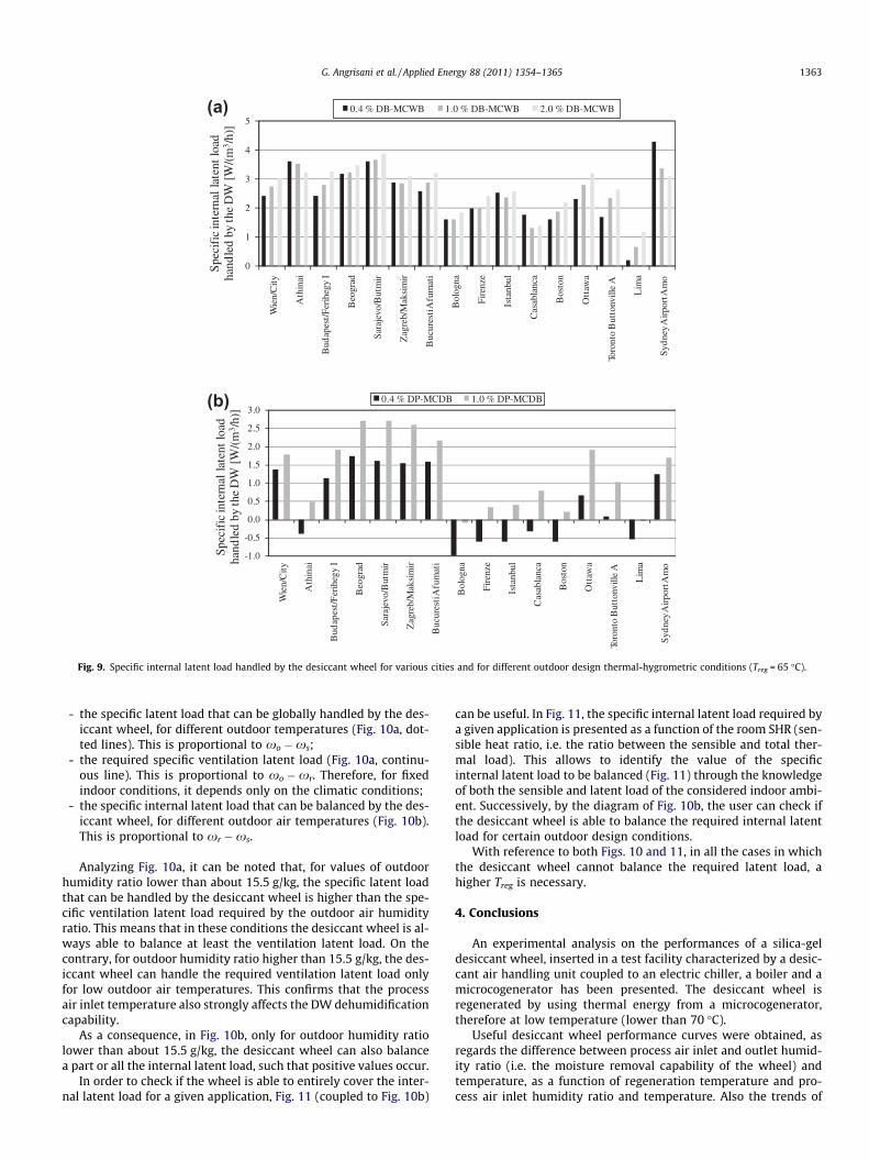
In Fig. 9a and b, the maximum specific internal latent load thatcould be handled by the desiccant wheel (independently of thetype of internal latent load) is presented, considering the ASHRAEcooling and dehumidification design data, respectively. This loadis proportional to xr �xs, with xs experimentally evaluated as re-ported above.
In Fig. 9b, note that for the cities in which the ventilation latentload cannot be completely handled by the desiccant wheel (be-cause xs > xr, as occurs, for example, in Bologna), no internal la-tent load can be balanced by the wheel, such that negativevalues are shown. In these cases, the lower the ventilation latentload covered by the DW with respect to the required value(Fig. 8b), the higher the absolute value of the internal latent loadreported in Fig. 9b.
Thus, in these cases, a higher Treg is necessary and the onlywaste heat from MCHP is not sufficient for regeneration process.
The results reported in Fig. 9, for given cities, can be generalizedfor any climatic condition, which is the main purpose of Fig. 10,where the following parameters have been reported as a functionof outdoor air humidity ratio:
0
1
2
3
4
5
Wie
n/C
ity
Ath
inai
Bud
apes
t/F
erih
egy
I
Beo
grad
Sar
ajev
o/B
utm
ir
Zag
reb/
Mak
sim
ir
Buc
ures
ti A
fum
ati
Bol
ogna
Fir
enze
Ista
nbul
Cas
abla
nca
Bos
ton
Ott
awa
Toro
nto
But
tonv
ille
A
Lim
a
Syd
ney
Air
port
Am
o
Spe
cifi
c in
tern
al l
aten
t lo
ad
hand
led
by
the
DW
[W
/(m
3 /h)
]
0.4 % DB-MCWB 1.0 % DB-MCWB 2.0 % DB-MCWB
-1.0
-0.5
0.0
0.5
1.0
1.5
2.0
2.5
3.0
Wie
n/C
ity
Ath
inai
Bud
apes
t/F
erih
egy
I
Beo
grad
Sar
ajev
o/B
utm
ir
Zag
reb/
Mak
sim
ir
Buc
ures
ti A
fum
ati
Bol
ogna
Fir
enze
Ista
nbul
Cas
abla
nca
Bos
ton
Ott
awa
Toro
nto
But
tonv
ille
A
Lim
a
Syd
ney
Air
port
Am
o
Spe
cifi
c in
tern
al l
aten
t lo
ad
hand
led
by
the
DW
[W
/(m
3 /h)
]
0.4 % DP-MCDB 1.0 % DP-MCDB
(a)
(b)
Fig. 9. Specific internal latent load handled by the desiccant wheel for various cities and for different outdoor design thermal-hygrometric conditions (Treg = 65 �C).
G. Angrisani et al. / Applied Energy 88 (2011) 1354–1365 1363
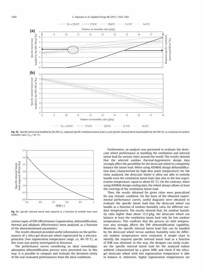
- the specific latent load that can be globally handled by the des-iccant wheel, for different outdoor temperatures (Fig. 10a, dot-ted lines). This is proportional to xo �xs;
- the required specific ventilation latent load (Fig. 10a, continu-ous line). This is proportional to xo �xr. Therefore, for fixedindoor conditions, it depends only on the climatic conditions;
- the specific internal latent load that can be balanced by the des-iccant wheel, for different outdoor air temperatures (Fig. 10b).This is proportional to xr �xs.
Analyzing Fig. 10a, it can be noted that, for values of outdoorhumidity ratio lower than about 15.5 g/kg, the specific latent loadthat can be handled by the desiccant wheel is higher than the spe-cific ventilation latent load required by the outdoor air humidityratio. This means that in these conditions the desiccant wheel is al-ways able to balance at least the ventilation latent load. On thecontrary, for outdoor humidity ratio higher than 15.5 g/kg, the des-iccant wheel can handle the required ventilation latent load onlyfor low outdoor air temperatures. This confirms that the processair inlet temperature also strongly affects the DW dehumidificationcapability.
As a consequence, in Fig. 10b, only for outdoor humidity ratiolower than about 15.5 g/kg, the desiccant wheel can also balancea part or all the internal latent load, such that positive values occur.
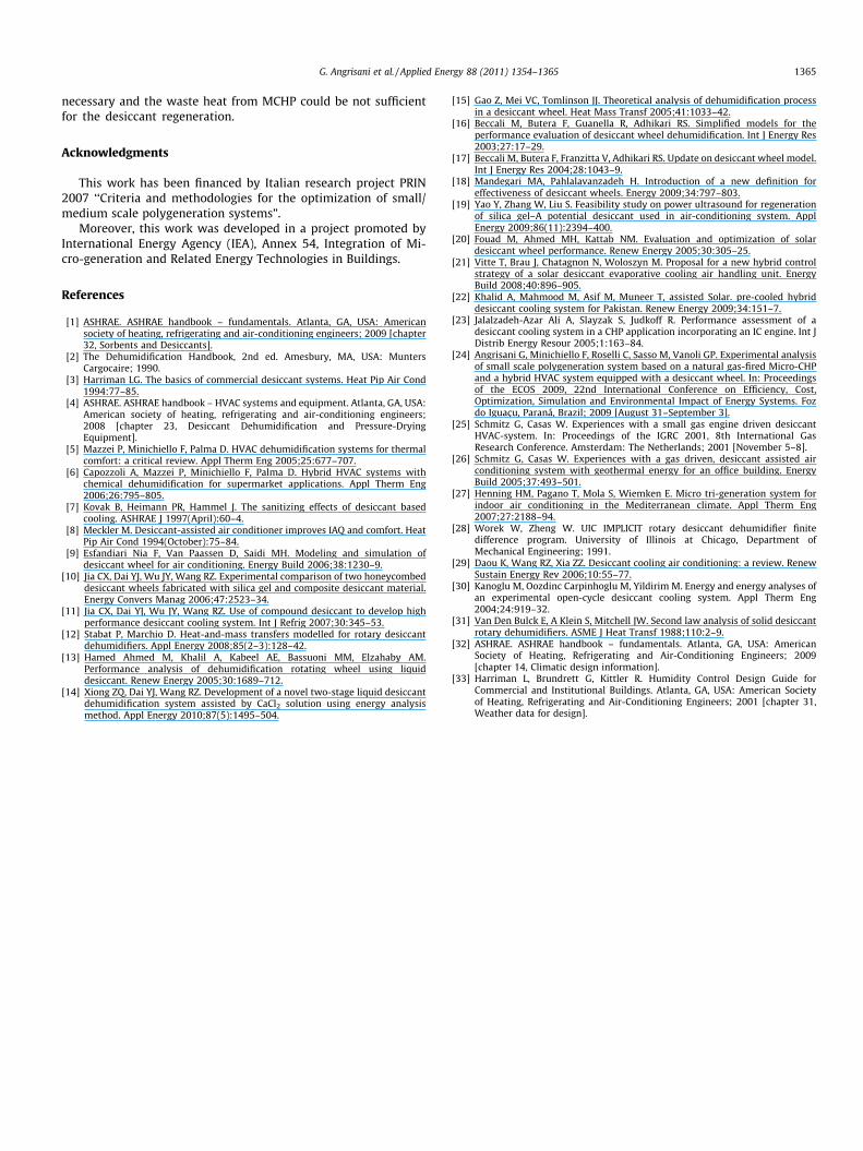
In order to check if the wheel is able to entirely cover the inter-nal latent load for a given application, Fig. 11 (coupled to Fig. 10b)
can be useful. In Fig. 11, the specific internal latent load required bya given application is presented as a function of the room SHR (sen-sible heat ratio, i.e. the ratio between the sensible and total ther-mal load). This allows to identify the value of the specificinternal latent load to be balanced (Fig. 11) through the knowledgeof both the sensible and latent load of the considered indoor ambi-ent. Successively, by the diagram of Fig. 10b, the user can check ifthe desiccant wheel is able to balance the required internal latentload for certain outdoor design conditions.
With reference to both Figs. 10 and 11, in all the cases in whichthe desiccant wheel cannot balance the required latent load, ahigher Treg is necessary.
4. Conclusions
An experimental analysis on the performances of a silica-geldesiccant wheel, inserted in a test facility characterized by a desic-cant air handling unit coupled to an electric chiller, a boiler and amicrocogenerator has been presented. The desiccant wheel isregenerated by using thermal energy from a microcogenerator,therefore at low temperature (lower than 70 �C).
Useful desiccant wheel performance curves were obtained, asregards the difference between process air inlet and outlet humid-ity ratio (i.e. the moisture removal capability of the wheel) andtemperature, as a function of regeneration temperature and pro-cess air inlet humidity ratio and temperature. Also the trends of
0.0
0.5
1.0
1.5
2.0
2.5
3.0
3.5
0.5 0.6 0.7 0.8 0.9 1
Spe
cifi
c in
tern
al l
aten
t lo
ad re
quir
ed [
W/(
m3 /
h)]
SHR [-]
Fig. 11. Specific internal latent load required as a function of sensible heat ratio(SHR).
0
1
2
3
4
5
6
78 9 10 11 12 13 14 15 16 17 18
Outdoor air humidity ratio [g/kg]Sp
ecif
ic la
tent
load
hand
led
by th
e D
W [
W/(
m3 /h
)]
To = 25.0°C 27.0°C 29.0°C 31.5°C 34.5°C
Req
uire
d sp
ecif
ic v
entil
atio
n
l
aten
t loa
d [W
/(m
3 /h)]
-2
-1
0
1
2
3
4
5
6
8 9 10 11 12 13 14 15 16 17 18
Outdoor air humidity ratio [g/kg]
Spec
ific
inte
rnal
late
nt lo
ad
hand
led
by th
e D
W [
W/(
m3 /h
)]
To = 25.0°C 27.0°C 29.0°C 31.5°C 34.5°C
(a)
(b)
Fig. 10. Specific latent load handled by the DW (a), required specific ventilation latent load (a) and specific internal latent load handled by the DW (b), as a function of outdoorhumidity ratio (Treg = 65 �C).
1364 G. Angrisani et al. / Applied Energy 88 (2011) 1354–1365
various types of DW effectiveness (regeneration, dehumidification,thermal and adiabatic effectiveness) were analyzed, as a functionof the abovementioned parameters.
The results obtained provided useful information on the perfor-mances of a silica-gel desiccant wheel regenerated by a microco-generator (low regeneration temperature range, i.e. 40–70 �C), asthis issue was poorly investigated in literature.
The performance curves considering an ideal isoenthalpycadsorption dehumidification process were presented too. In thisway, it is possible to compare and evaluate the deviation entityof the real evaluated performances from the ideal conditions.
Furthermore, an analysis was presented to evaluate the desic-cant wheel performance in handling the ventilation and internallatent load for various cities around the world. The results showedthat the selected outdoor thermal-hygrometric design datastrongly affect the possibility for the desiccant wheel to completelybalance the latent load. When using ASHRAE design dehumidifica-tion data (characterized by high dew point temperature) for thecities analyzed, the desiccant wheel is often not able to entirelyhandle even the ventilation latent load (due also to the low regen-eration temperature, equal to about 65 �C). On the contrary, whenusing ASHRAE design cooling data, the wheel always allows at leastthe covering of the ventilation latent load.
Then, the results obtained for given cities were generalizedfor any climatic condition. On the basis of the obtained experi-mental performance curves, useful diagrams were obtained toevaluate the specific latent load that the desiccant wheel canhandle as a function of outdoor humidity ratio, for different out-door temperatures. The results showed that, for outdoor humid-ity ratio higher than about 15.5 g/kg, the desiccant wheel canbalance at least the ventilation latent load only for low outdoortemperatures. This confirms that the process air inlet tempera-ture also strongly affects the DW dehumidification capability.Moreover, the specific internal latent load that can be handledby the desiccant wheel versus outdoor humidity ratio for differ-ent outdoor temperatures were evaluated. A simple chart toidentify the required specific internal latent load as a functionof SHR was obtained. In this way, the designer can easily evalu-ate the specific internal latent load for the analyzed indoorambient (characterized by a given SHR) and check if the silica-gel desiccant wheel with low regeneration temperature is ableto balance it, otherwise, higher regeneration temperatures are
G. Angrisani et al. / Applied Energy 88 (2011) 1354–1365 1365
necessary and the waste heat from MCHP could be not sufficientfor the desiccant regeneration.
Acknowledgments
This work has been financed by Italian research project PRIN2007 ‘‘Criteria and methodologies for the optimization of small/medium scale polygeneration systems”.
Moreover, this work was developed in a project promoted byInternational Energy Agency (IEA), Annex 54, Integration of Mi-cro-generation and Related Energy Technologies in Buildings.
References
[1] ASHRAE. ASHRAE handbook – fundamentals. Atlanta, GA, USA: Americansociety of heating, refrigerating and air-conditioning engineers; 2009 [chapter32, Sorbents and Desiccants].
[2] The Dehumidification Handbook, 2nd ed. Amesbury, MA, USA: MuntersCargocaire; 1990.
[3] Harriman LG. The basics of commercial desiccant systems. Heat Pip Air Cond1994:77–85.
[4] ASHRAE. ASHRAE handbook – HVAC systems and equipment. Atlanta, GA, USA:American society of heating, refrigerating and air-conditioning engineers;2008 [chapter 23, Desiccant Dehumidification and Pressure-DryingEquipment].
[5] Mazzei P, Minichiello F, Palma D. HVAC dehumidification systems for thermalcomfort: a critical review. Appl Therm Eng 2005;25:677–707.
[6] Capozzoli A, Mazzei P, Minichiello F, Palma D. Hybrid HVAC systems withchemical dehumidification for supermarket applications. Appl Therm Eng2006;26:795–805.
[7] Kovak B, Heimann PR, Hammel J. The sanitizing effects of desiccant basedcooling. ASHRAE J 1997(April):60–4.
[8] Meckler M. Desiccant-assisted air conditioner improves IAQ and comfort. HeatPip Air Cond 1994(October):75–84.
[9] Esfandiari Nia F, Van Paassen D, Saidi MH. Modeling and simulation ofdesiccant wheel for air conditioning. Energy Build 2006;38:1230–9.
[10] Jia CX, Dai YJ, Wu JY, Wang RZ. Experimental comparison of two honeycombeddesiccant wheels fabricated with silica gel and composite desiccant material.Energy Convers Manag 2006;47:2523–34.
[11] Jia CX, Dai YJ, Wu JY, Wang RZ. Use of compound desiccant to develop highperformance desiccant cooling system. Int J Refrig 2007;30:345–53.
[12] Stabat P, Marchio D. Heat-and-mass transfers modelled for rotary desiccantdehumidifiers. Appl Energy 2008;85(2–3):128–42.
[13] Hamed Ahmed M, Khalil A, Kabeel AE, Bassuoni MM, Elzahaby AM.Performance analysis of dehumidification rotating wheel using liquiddesiccant. Renew Energy 2005;30:1689–712.
[14] Xiong ZQ, Dai YJ, Wang RZ. Development of a novel two-stage liquid desiccantdehumidification system assisted by CaCl2 solution using energy analysismethod. Appl Energy 2010;87(5):1495–504.
[15] Gao Z, Mei VC, Tomlinson JJ. Theoretical analysis of dehumidification processin a desiccant wheel. Heat Mass Transf 2005;41:1033–42.
[16] Beccali M, Butera F, Guanella R, Adhikari RS. Simplified models for theperformance evaluation of desiccant wheel dehumidification. Int J Energy Res2003;27:17–29.
[17] Beccali M, Butera F, Franzitta V, Adhikari RS. Update on desiccant wheel model.Int J Energy Res 2004;28:1043–9.
[18] Mandegari MA, Pahlalavanzadeh H. Introduction of a new definition foreffectiveness of desiccant wheels. Energy 2009;34:797–803.
[19] Yao Y, Zhang W, Liu S. Feasibility study on power ultrasound for regenerationof silica gel–A potential desiccant used in air-conditioning system. ApplEnergy 2009;86(11):2394–400.
[20] Fouad M, Ahmed MH, Kattab NM. Evaluation and optimization of solardesiccant wheel performance. Renew Energy 2005;30:305–25.
[21] Vitte T, Brau J, Chatagnon N, Woloszyn M. Proposal for a new hybrid controlstrategy of a solar desiccant evaporative cooling air handling unit. EnergyBuild 2008;40:896–905.
[22] Khalid A, Mahmood M, Asif M, Muneer T, assisted Solar. pre-cooled hybriddesiccant cooling system for Pakistan. Renew Energy 2009;34:151–7.
[23] Jalalzadeh-Azar Ali A, Slayzak S, Judkoff R. Performance assessment of adesiccant cooling system in a CHP application incorporating an IC engine. Int JDistrib Energy Resour 2005;1:163–84.
[24] Angrisani G, Minichiello F, Roselli C, Sasso M, Vanoli GP. Experimental analysisof small scale polygeneration system based on a natural gas-fired Micro-CHPand a hybrid HVAC system equipped with a desiccant wheel. In: Proceedingsof the ECOS 2009, 22nd International Conference on Efficiency, Cost,Optimization, Simulation and Environmental Impact of Energy Systems. Fozdo Iguaçu, Paraná, Brazil; 2009 [August 31–September 3].
[25] Schmitz G, Casas W. Experiences with a small gas engine driven desiccantHVAC-system. In: Proceedings of the IGRC 2001, 8th International GasResearch Conference. Amsterdam: The Netherlands; 2001 [November 5–8].
[26] Schmitz G, Casas W. Experiences with a gas driven, desiccant assisted airconditioning system with geothermal energy for an office building. EnergyBuild 2005;37:493–501.
[27] Henning HM, Pagano T, Mola S, Wiemken E. Micro tri-generation system forindoor air conditioning in the Mediterranean climate. Appl Therm Eng2007;27:2188–94.
[28] Worek W, Zheng W. UIC IMPLICIT rotary desiccant dehumidifier finitedifference program. University of Illinois at Chicago, Department ofMechanical Engineering; 1991.
[29] Daou K, Wang RZ, Xia ZZ. Desiccant cooling air conditioning: a review. RenewSustain Energy Rev 2006;10:55–77.
[30] Kanoglu M, Oozdinc Carpinhoglu M, Yildirim M. Energy and energy analyses ofan experimental open-cycle desiccant cooling system. Appl Therm Eng2004;24:919–32.
[31] Van Den Bulck E, A Klein S, Mitchell JW. Second law analysis of solid desiccantrotary dehumidifiers. ASME J Heat Transf 1988;110:2–9.
[32] ASHRAE. ASHRAE handbook – fundamentals. Atlanta, GA, USA: AmericanSociety of Heating, Refrigerating and Air-Conditioning Engineers; 2009[chapter 14, Climatic design information].
[33] Harriman L, Brundrett G, Kittler R. Humidity Control Design Guide forCommercial and Institutional Buildings. Atlanta, GA, USA: American Societyof Heating, Refrigerating and Air-Conditioning Engineers; 2001 [chapter 31,Weather data for design].