Description of Device Functions Cerabar S PMP71 with MID ...
60
Products Solutions Services BA00413P/00/EN/13.16 71335863 Valid for software version: 02.10.54 Operating Instructions – Description of Device Functions Cerabar S PMP71 with MID Part Certificate Process pressure measurement
-
Upload
khangminh22 -
Category
Documents
-
view
2 -
download
0
Transcript of Description of Device Functions Cerabar S PMP71 with MID ...

Products Solutions ServicesBA00413P/00/EN/13.1671335863
Valid for software version:02.10.54
Operating Instructions – Description of Device FunctionsCerabar S PMP71 with MID Part Certificate
Process pressure measurement

Cerabar S 4 to 20mA HART
2 Endress+Hauser
A0023555
Make sure the document is stored in a safe place such that it is always available when working on or with the device. To avoid danger to individuals or the facility, read the "Basic safety instructions" section carefully, as well as all other safety instructions in the document that are specific toworking procedures. The manufacturer reserves the right to modify technical data without prior notice. Your Endress+Hauser Sales Center will supply you with current information and updates to these Instructions.
Order code:
Ext. ord. cd.:
Ser. no.:
www.endress.com/deviceviewer Endress+Hauser
Operations App
XXXXXXXXXXXX
XXXXX-XXXXXX
XXX.XXXX.XX
Serial number
1.
3.
2.

Cerabar S 4 to 20mA HART
Endress+Hauser 3
Table of contents
1 Notes on use . . . . . . . . . . . . . . . . . . . . . . . 41.1 Finding parameter description using ID numbers . 41.2 Finding function group using graphic
representation . . . . . . . . . . . . . . . . . . . . . . . . . . . . . . 41.3 Finding parameter description using parameter
names (index) . . . . . . . . . . . . . . . . . . . . . . . . . . . . . . 4
2 Finding parameter description using ID numbers. . . . . . . . . . . . . . . . . . . . . . . . . . . 5
3 Graphic representation of function groups . . . . . . . . . . . . . . . . . . . . . . . . . . . . 7
4 Pressure measurement . . . . . . . . . . . . . . 84.1 Calibration with reference pressure . . . . . . . . . . . . 84.2 Calibration without reference pressure . . . . . . . . . 9
5 Description of parameters . . . . . . . . . . 11
6 Troubleshooting . . . . . . . . . . . . . . . . . . . 396.1 Messages . . . . . . . . . . . . . . . . . . . . . . . . . . . . . . . . 396.2 Response of outputs to errors . . . . . . . . . . . . . . . 466.3 Confirming messages . . . . . . . . . . . . . . . . . . . . . . 47
7 Appendix . . . . . . . . . . . . . . . . . . . . . . . . . 487.1 Operating menu for onsite display and digital
communication . . . . . . . . . . . . . . . . . . . . . . . . . . . 48
Index. . . . . . . . . . . . . . . . . . . . . . . . . . . . . 55
Notes on use Cerabar S 4 to 20mA HART
4 Endress+Hauser
1 Notes on useSection 5 describes all the parameters in the order of how they appear in the menu. Section 4 describe typical configuration examples.
Section 1.1 to Section 1.3 describe ways of finding a certain parameter description more easily.
1.1 Finding parameter description using ID numbersEach parameter is shown on the onsite display with a unique identification number (ID). All the parameters are listed in numerical order in Section 2. The page reference/link takes you to the parameter in question.In the operating program, additional parameters and, to an extent, other parameters are displayed. These parameters are not shown in Section 2. You can find these parameters by means of the index. See also Section 1.3.
1.2 Finding function group using graphic representationSection 3 provides an outline of all of the function groups in tables. The page reference/link takes you to the function group in question. In Section 5, all of the parameters in a function group are summarized in a table.
1.3 Finding parameter description using parameter names (index)
The index lists all the parameters in alphabetical order. The page reference/link takes you to the parameter in question.

Cerabar S 4 to 20mA HART Finding parameter description using ID numbers
Endress+Hauser 5
2 Finding parameter description using ID numbers
ID number Parameter name Description, see Page
014 DOWNLOAD SELECT 33015 FULL PRESSURE See 1)
016 EMPTY PRESSURE See 1)
017 FULL CALIB. See 1)
018 EMPTY CALIB. See 1)
021 SET LRV See 1)
022 SET URV See 1)
036 PREAMBLE NUMBER 25042 CURR. TRIM 20mA 38043 OFFSET 4mA TRIM 38044 OFFSET 20mA TRIM 38045 CURR. TRIM 4mA 38046 ALARM STATUS 35047 ENTER RESET CODE 32048 INSERT PIN No 33055 CUST. TAG NUMBER 26060 PRESS. ENG. UNIT 16075 CUSTOMER UNIT P 16079 LANGUAGE 11245 SET LRV – "Pressure" measuring mode 13 or 16246 SET URV – "Pressure" measuring mode 13 or 16247 DAMPING TIME 13, 17250 SENSOR SER. No. 29254 OUTPUT CURRENT 21264 SOFTWARE VERSION 26266 HARDWARE REV. 26270 SIM. CURRENT 34271 HART MESSAGE 25272 ADDITIONAL INFO. 26301 PRESSURE – "Pressure" measuring mode 31305 LONG TAG NUMBER 26309 GET LRV 17310 GET URV 17317 CUST.UNIT FACT.P 16318 TEMP. ENG. UNIT – "Pressure" measuring mode 18 319 CALIB. OFFSET 14332 Pmin ALARM WINDOW 36333 Pmax ALARM WINDOW 36334 Tmin ALARM WINDOW 37335 Tmax ALARM WINDOW 37336 ALARM DELAY 36339 DISPLAY CONTRAST 20342 SET MAX. ALARM 23343 SET MIN. CURRENT 23345 BUS ADDRESS 24350 DEVICE DESIGN. 26352 CONFIG RECORDER 26354 DEVICE SERIAL No 26357 PCB TEMPERATURE 26358 ALLOWED MIN. TEMP 26359 ALLOWED MAX. TEMP 26360 MAT. PROC. CONN. + 27362 SEAL TYPE 28363 DIP STATUS 27365 MAT. 29366 FILLING FLUID 29367 SENSOR TEMP. 31368 Tmin SENSOR 29369 Tmax SENSOR 29378 MEAS. VAL. TREND 31386 ELECTR. SERIAL NO. 26388 OUTPUT FAIL MODE 22

Finding parameter description using ID numbers Cerabar S 4 to 20mA HART
6 Endress+Hauser
389 MEASURING MODE 12, 15401 ACK. ALARM MODE 35409 OPERATING HOURS 32413 SIMULATION MODE 34414 SIM. PRESSURE 34419 MENU DESCRIPTOR 19423 ALTERNATE DATA 19432 MANUFACTOR ID 25434 CORRECTED PRESS. – "Pressure" measuring mode 31476 SIM. ERROR NO. 34480 ALARM DISPL. TIME 36481 HART DATE 25482 PROC. CONN. TYPE 27484 PRESS. SENS LOLIM 29485 PRESS. SENS HILIM 29487 SENS H/WARE REV 29500 ACK. ALARM 35563 POS. INPUT VALUE 13 or 14564 LAST DIAG. CODE 35570 Pmax PROC. CONN. 27581 SENSOR MEAS.TYPE 29584 SENSOR PRESSURE – "Pressure" measuring mode 31591 MINIMUM SPAN 29595 SELECT ALARMTYPE 36597 ALT.CURR.OUTPUT 22600 SELECT ALARMTYPE 36603 RESET ALL ALARMS 35679 MEASURED VALUE – "Pressure" 30 688 MAIN DATA FORMAT 19694 CURR. CHARACT. – "Pressure" 22696 CURR. CHARACT. – "Height" 22699 DEVICE REVISION 24764 CURR. CHARACT. – "Tank content" 22802 DEVICE TYPE, Cerabar S 24831 HistoROM AVAIL. 33832 HistoROM CONTROL 33836 SAFETY LOCKSTATE See 1)
838 SAFETY PASSWORD See 1)
840 DIGITS SET 20841 DIGITS SET See 1)
844 ACK. ALARM MODE See 1)
845 MEASURING MODE See 1)
847 CALIB. OFFSET See 1)
852 SET LRV See 1)
853 SET URV See 1)
855 DAMPING TIME See 1)
856 CONF. PASSWORD See 1)
875 CURRENT OUTPUT See 1)
1) For further information, see the Cerabar S Functional Safety Manual (SD00190P).
ID number Parameter name Description, see Page
Cerabar S 4 to 20mA HART Graphic representation of function groups
Endress+Hauser 7
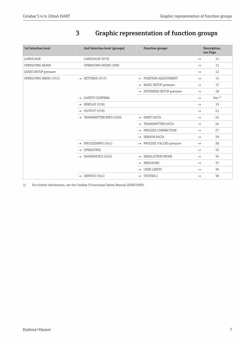
3 Graphic representation of function groups
1st Selection level 2nd Selection level (groups) Function groups Description, see Page
LANGUAGE LANGUAGE (079) 11
OPERATING MODE OPERATING MODE (389) 11
QUICK SETUP pressure 12
OPERATING MENU (555) SETTINGS (557) POSITION ADJUSTMENT 14
BASIC SETUP pressure 15
EXTENDED SETUP pressure 18
SAFETY CONFIRM. See 1)
DISPLAY (558) 19
OUTPUT (559) 21
TRANSMITTER INFO (560) HART DATA 24
TRANSMITTER DATA 26
PROCESS CONNECTION 27
SENSOR DATA 29
PROCESSINFO (561) PROCESS VALUES pressure 30
OPERATING 32
DIAGNOSTICS (562) SIMULATION MODE 34
MESSAGES 35
USER LIMITS 36
SERVICE (561) SYSTEM 2 38
1) For further information, see the Cerabar S Functional Safety Manual (SD00190P).

Pressure measurement Cerabar S 4 to 20mA HART
8 Endress+Hauser
4 Pressure measurement
4.1 Calibration with reference pressureExample:In this example, a device with a 10 bar (150 psi) sensor is configured for the 0 to +4 bar (60 psi) measuring range, i.e. 0 bar is assigned to the 4 mA value and 4 bar (60 psi) to the 20 mA value.
Prerequisite:• The pressure values 0 bar and 4 bar (60 psi) can be specified. The device is already
installed, for example.
• See also Operating Instructions for Cerabar S (BA00412P), "Pressure measurement" section.
• For a description of the parameters mentioned, see– Page 11, Table 1: MEASURING MODE– Page 14, Table 3: POSITION ADJUSTMENT– Page 15, Table 4: BASIC SETUP.
• For a description of further relevant parameters, see– Page 18, Table 5: EXTENDED SETUP– Page 30, Table 12: PROCESS VALUES.

Cerabar S 4 to 20mA HART Pressure measurement
Endress+Hauser 9
You can also specify a customer-specific unit. See parameter description for PRESS. ENG. UNIT (Page 16).
4.2 Calibration without reference pressureExample:In this example, a device with a 400 mbar (6 psi) sensor is configured for the 0 to +300 mbar (4.5 psi) measuring range, i.e. 0 mbar is assigned to the 4 mA value and 300 mbar (4.5 psi) to the 20 mA value.
Prerequisite:• This is a theoretical calibration, i.e. the pressure values for the
lower range and upper range value are known.
• See also Operating Instructions for Cerabar S (BA00412P), "Pressure measurement" section.
Description
1 Carry out position adjustment if necessary. See Page 14, Table 5: POSITION ADJUSTMENT.
P01-MIDxxxxx-05-xx-xx-xx-004
Fig. 1: Calibration with reference pressure
1 See Table, Step 5.2 See Table, Step 6.
2 If necessary, select the "Pressure" measuring mode via the MEASURING MODE parameter.
WARNING!
Changing the measuring mode affects the span (URV)!This situation can result in product overflow.‣ If the measuring mode is changed, the span
setting (URV) must be verified in the "CALIBRATION" "BASIC SETUP" operating menu and, if necessary, reconfigured!
Onsite display:Menu path: GROUP SELECTION MEASURING MODE
Digital communicationMenu path: OPERATING MENU SETTINGSBASIC SETUP MEASURING MODE
3 Onsite display:Select BASIC SETUP function group. Menu path: GROUP SELECTION OPERATING MENU SETTINGS BASIC SETUP
4 Select a pressure unit via the PRESS. ENG. UNIT parameter, here mbar for example.
5 The pressure for the lower range value (4 mA value) is present at the device, here 0 mbar for example.
Select GET LRV parameter.
Confirm value present. The pressure value present is assigned to the lower current value (4 mA).
6 The pressure for the upper range value (20 mA value) is present at the device, here 300 mbar (4.5 psi) for example.
Select GET URV parameter.
Confirm value present. The pressure value present is assigned to the upper current value (20 mA).
7 Result: The measuring range is configured for 0 to +300 mbar (4.5 psi).
20
4
I[mA]
0 4 p[bar]
➀
➁

Pressure measurement Cerabar S 4 to 20mA HART
10 Endress+Hauser
• Due to the orientation of the device, there may be a shift in the measured value, i.e. when the container is empty or partially filled, the MEASURED VALUE parameter does not display zero. For information on how to perform position adjustment, see also Page 14, Table 3: Position adjustment.
• For a description of the parameters mentioned, see– Page 11, Table 1: MEASURING MODE– Page 14, Table 3: POSITION ADJUSTMENT– Page 15, Table 4: BASIC SETUP.
• For a description of further relevant parameters, see– Page 18, Table 5: EXTENDED SETUP– Page 30, Table 12: PROCESS VALUES.
• You can also perform calibration without reference pressure by means of the QUICK SETUP menu. See Page 12 ff, Table 2: QUICK SETUP menu.
• You can also specify a customer-specific unit. See parameter description for PRESS. ENG. UNIT (Page 16).
Description
1 If necessary, select the "Pressure" measuring mode via the MEASURING MODE parameter.
WARNING!
Changing the measuring mode affects the span (URV)!This situation can result in product overflow.‣ If the measuring mode is changed, the span
setting (URV) must be verified in the "CALIBRATION" "BASIC SETUP" operating menu and, if necessary, reconfigured!
Onsite display:Menu path: GROUP SELECTION MEASURING MODE
Digital communicationMenu path: OPERATING MENU SETTINGS BASIC SETUP MEASURING MODE
P01-PMP71xxx-19-xx-xx-xx-000
P01-MIDxxxxx-05-xx-xx-xx-004
Fig. 2: Calibration without reference pressure
1 See Table, Step 4.2 See Table, Step 5.
2 Onsite display:Select BASIC SETUP function group. Menu path: GROUP SELECTION OPERATING MENU SETTINGS BASIC SETUP
3 Select a pressure unit via the PRESS. ENG. UNIT parameter, here mbar for example.
4 Select SET LRV parameter.
Enter value, here 0 mbar, for the SET LRV
parameter and confirm. This pressure value is assigned to the lower current value (4 mA).
5 Select SET URV parameter.
Enter the value for the "SET URV" parameter (here 300 mbar (4.5 psi)) and confirm. This pressure value is assigned to the upper current value (20 mA).
6 Result:The measuring range is configured for 0 to +300 mbar (4.5 psi).
20
4
I[mA]
0 4 p[bar]
➀
➁

Cerabar S 4 to 20mA HART Description of parameters
Endress+Hauser 11
5 Description of parameters• The following tables list all the parameters as per the menu structure. Each table
corresponds to a function group in the menu tree. The overall menu structure is illustrated in Section 7.1.
• The menu structure for local operation and digital communication are slightly different. The differences mainly affect the MEASURING MODE and LANGUAGE parameters.
• In the operating program or HART handheld terminal, additional parameters are displayed. These parameters are marked accordingly .
• The menu path is indicated in the header of each table. You can use this path to get to the parameters in question.
• The menu has a different structure depending on the measuring mode selected. This means that some function groups are only displayed for one measuring mode. If certain requirements have to be met for a function group, these are listed in the first row of the table.
• Some parameters are only displayed if other parameters are appropriately configured. • Parameter names are written in upper case in the text. • In the "Parameter name" column, the unique identification number (ID) of the parameter
is indicated in brackets. This ID only appears on the onsite display.
P01-MIDxxxxx-19-xx-xx-EN-001
Fig. 3: 1st selection level in menu, LANGUAGE ( see Page 11, Table 1)
1)
1)
1)
2)
1) Display via on-site display only
2) Display via digital communication Pressure
OPERATING MENU
Measured value
GROUP SELECTION
LANGUAGE MEASURING MODE QUICK SETUP
MEASURING MODE
Level (notfor PMP71 with MID)
provided
Table 1: GROUP SELECTION LANGUAGE – Onsite display
Parameter name Description
LANGUAGE (079)Options
Select the menu language for the onsite display.
• In the operating program and in the HART handheld terminal, the LANGUAGE parameter is arranged in the DISPLAY function group.
• Select the menu language for the operating program via the "Options" menu "Settings" "Language" tab "Tool Language" field.
Options:• Deutsch• English• Français• Italiano• Español• Nederlands• Chinese (CHS)• Japanese (JPN)
Factory setting:English

Description of parameters Cerabar S 4 to 20mA HART
12 Endress+Hauser
P01-MIDxxxxx-19-xx-xx-EN-003
Fig. 4: Quick Setup menu for the "Pressure" measuring mode
1)
1)
2)
1)
1) Display via on-site display only
2) Display via digital communication
SET LRV
SET URV
DAMPING VALUE
POS. INPUT VALUE
Pressure
OPERATING MENU
Measured value
GROUP SELECTION
LANGUAGE MEASURING MODE QUICK SETUP
MEASURING MODE
Level (notfor PMP71 with MID)
provided
Table 2: (GROUP SELECTION ) QUICK SETUP "Pressure"
Parameter name Description
This menu displays the most important parameters for the "Pressure" measuring mode.
Prerequisite:• MEASURING MODE = Pressure
Note:See also– Page 15 ff, Table 6: BASIC SETUP– Page 18, Table 13: EXTENDED SETUP– Page 30 ff, Table 23: PROCESS VALUES– Page 8 ff, Section 4 "Pressure measurement".
MEASURING MODE Options
Select the measuring mode.The operating menu is structured according to the selected measuring mode.
WARNING!
Changing the measuring mode affects the span (URV)!This situation can result in product overflow.‣ If the measuring mode is changed, the span setting (URV) must be verified in
the "CALIBRATION" "BASIC SETUP" operating menu and, if necessary, reconfigured!
Prerequisite:• Digital communication
Options:• Pressure
Factory setting:• Pressure

Cerabar S 4 to 20mA HART Description of parameters
Endress+Hauser 13
P01-MIDxxxxx-19-xx-xx-EN-026
Fig. 5: Function group POSITION ADJUSTMENT
POS. INPUT VALUE (563)Entry
Position adjustment – the pressure difference between zero (set point) and the measured pressure need not be known. To correct the pressure difference, you need a reference measured value (e. g. from a reference device). Due to the orientation of the device, there may be a shift in the measured value, i.e. for example, when the container is empty or partially filled, the MEASURED VALUE parameter does not display zero or the desired value.
Example:– MEASURED VALUE = 0.5 mbar (0.0075 psi)– For the POS. INPUT VALUE parameter, specify the desired set point for the
MEASURED VALUE, e.g. 2 mbar (0.03 psi).(MEASURED VALUEnew = POS. INPUT VALUE)
– MEASURED VALUE (after entry for POS. INPUT VALUE) = 2.0 mbar ( 0.03 psi)– The CALIB. OFFSET parameter displays the resulting pressure difference (offset)
by which the MEASURED VALUE was corrected.The following applies: CALIB. OFFSET = MEASURED VALUEold – POS. INPUT VALUE, here: CALIB. OFFSET = 0.5 mbar (0.0075 psi) – 2.0 mbar (0.03 psi) = – 1.5 mbar (-0.0225 psi)
– The current value is also corrected.
Factory setting:0.0
SET LRV (245)Entry
Set lower range value – without reference pressure.Enter pressure value for the lower current value (4 mA).
Factory setting:0.0 or as per order specifications
SET URV (246)Entry
Set upper range value – without reference pressure.Enter pressure value for the upper current value (20 mA).
Factory setting:High sensor limit (see PRESS. SENS HILIM, Page 29) or as per order specifications
DAMPING VALUE (247)Entry
Enter damping time (time constant ).The damping affects the speed at which all subsequent elements, such as the onsite display, measured value and current output react to a change in the pressure.
Input range:0.0 to 999.0 s
Factory setting:2.0 s or as per order specifications
Table 2: (GROUP SELECTION ) QUICK SETUP "Pressure"
Parameter name Description
1)
1)LANGUAGE
BASIC SETUP
DISPLAYSETTINGS
POSITION ADJUSTMENT
OPERATING MENU
GROUP SELECTION
Measured value
EXTENDED SETUP
CALIB. OFFSET
POS. INPUT VALUE
1) Display viaon-site display only

Description of parameters Cerabar S 4 to 20mA HART
14 Endress+Hauser
Table 3: (GROUP SELECTION ) OPERATING MENU SETTINGS POSITION ADJUSTMENT
Parameter name Description
Due to the orientation of the device, there may be a shift in the measured value, i.e. when the container is empty or partially filled, the measured value does not display zero. Cerabar S provides two different options for carrying out position adjustment.
Recommendation:• The pressure difference between zero (set point) and the measured pressure need not be known.
– POS. INPUT VALUE• The pressure difference between zero (set point) and the measured pressure is known.
– CALIB. OFFSET
POS. INPUT VALUE (563)Entry
Position adjustment – the pressure difference between zero (set point) and the measured pressure need not be known. To correct the pressure difference, you need a reference measured value (e. g. from a reference device).
Example:– MEASURED VALUE = 0.5 mbar (0.0075 psi)– For the POS. INPUT VALUE parameter, specify the desired set point for the
MEASURED VALUE, e.g. 2.0 mbar (0.03 psi).(MEASURED VALUEnew = POS. INPUT VALUE)
– MEASURED VALUE (after entry for POS. INPUT VALUE) = 2.0 mbar ( 0.03 psi)– The CALIB. OFFSET parameter displays the resulting pressure difference (offset)
by which the MEASURED VALUE was corrected.The following applies: CALIB. OFFSET = MEASURED VALUEold – POS. INPUT VALUE, here: CALIB. OFFSET = 0.5 mbar (0.0075 psi) – 2.0 mbar (0.03 psi) = – 1.5 mbar (-0.0225 psi)
– The current value is also corrected.
Factory setting:0.0
CALIB. OFFSET (319)Entry
Position adjustment – the pressure difference between zero (set point) and the measured pressure is known.
Example:– MEASURED VALUE = 2.2 mbar (0.033 psi)– Via the CALIB. OFFSET parameter, enter the value by which the MEASURED
VALUE should be corrected. To correct the MEASURED VALUE to 0.0 mbar, you must enter the value 2.2 here.(MEASURED VALUE new = MEASURED VALUEold – CALIB. OFFSET)
– MEASURED VALUE (after entry for calib. offset) = 0.0 mbar– The current value is also corrected.
Factory setting:0.0
Cerabar S 4 to 20mA HART Description of parameters
Endress+Hauser 15
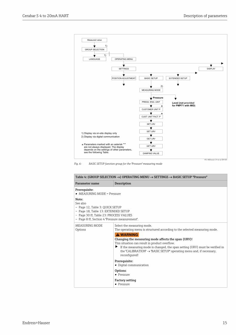
P01-MIDxxxxx-19-xx-xx-EN-005
Fig. 6: BASIC SETUP function group for the "Pressure" measuring mode
*
*
1)
2)
1)
* Parameters marked with an asterisk "*"are not always displayed. The displaydepends on the settings of other parameters,see the following Table.
LANGUAGE
Pressure
BASIC SETUP
DISPLAYSETTINGS
POSITION ADJUSTMENT
OPERATING MENU
GROUP SELECTION
Measured value
MEASURING MODE
EXTENDED SETUP
PRESS. ENG. UNIT
CUSTOMER UNIT P
CUST. UNIT FACT. P
SET LRV
DAMPING VALUE
GET LRV
GET URV
SET URV1) Display via on-site display only
2) Display via digital communication
Level (notfor PMP71 with MID)
provided
Table 4: (GROUP SELECTION ) OPERATING MENU SETTINGS BASIC SETUP "Pressure"
Parameter name Description
Prerequisite:• MEASURING MODE = Pressure
Note:See also– Page 12, Table 3: QUICK SETUP– Page 18, Table 13: EXTENDED SETUP– Page 30 ff, Table 23: PROCESS VALUES– Page 8 ff, Section 4 "Pressure measurement".
MEASURING MODEOptions
Select the measuring mode.The operating menu is structured according to the selected measuring mode.
WARNING!
Changing the measuring mode affects the span (URV)!This situation can result in product overflow.‣ If the measuring mode is changed, the span setting (URV) must be verified in
the "CALIBRATION" "BASIC SETUP" operating menu and, if necessary, reconfigured!
Prerequisite:• Digital communication
Options:• Pressure
Factory setting• Pressure

Description of parameters Cerabar S 4 to 20mA HART
16 Endress+Hauser
PRESS. ENG. UNIT (060)Options
Select pressure unit.If a new pressure unit is selected, all pressure-specific parameters are converted and displayed with the new unit.
Options:• mbar, bar• mmH2O, mH2O, inH2O, ftH2O• Pa, hPa, kPa, MPa• psi• mmHg, inHg• Torr• g/cm2, kg/cm2
• lb/ft2
• atm• gf/cm2, kgf/cm2
• User unit See also the following parameter description for CUSTOMER UNIT P and CUST.UNIT FACT.P.
Factory setting:Depends on the sensor nominal measuring range mbar or bar or as per order specifications
CUSTOMER UNIT P (075)Entry
Enter text (unit) for customer-specific pressure unit. You can enter a maximum of eight alphanumeric characters here. See also CUST.UNIT FACT.P.
Prerequisite:• PRESS. ENG. UNIT = User unit
Only the first five characters are shown on the onsite display. For example, if "crates" is specified as the customer-specific unit, "crate" is displayed. If the unit contains a slash, up to eight characters can be shown on the onsite display. The maximum number of characters in the counter is again limited to five. For example, if "crates/m2" is specified as the customer-specific unit, "crate/m2" is displayed. In FieldCare, all eight characters are displayed.In the HART handheld terminal, the customer-specific unit is only displayed in the CUSTOMER UNIT P parameter. The measured value is displayed with the additional text "User Unit".
Factory setting: _ _ _ _ _ _ _ _
CUST.UNIT FACT.P (317)Entry
Enter conversion factor for a customer-specific pressure unit. The conversion factor must be entered in relation to the SI unit "Pa". See also CUSTOMER UNIT P.
Prerequisite:• PRESS. ENG. UNIT = User unit
Example:– You want the measured value to be displayed in "PU" (PU: packing unit).– MEASURED VALUE =10,000 Pa i 1 PU– Entry CUSTOMER UNIT P: PU– Entry CUST.UNIT FACT.P: 0.0001– Result: MEASURED VALUE = 1 PU
Factory setting: 1.0
SET LRV (245)Entry
Set lower range value – without reference pressure.Enter pressure value for the lower current value (4 mA).
Factory setting:0.0 or as per order specifications
SET URV (246)Entry
Set upper range value – without reference pressure.Enter pressure value for the upper current value (20 mA).
Factory setting:High sensor limit ( see PRESS. SENS HILIM, Page 29)
Table 4: (GROUP SELECTION ) OPERATING MENU SETTINGS BASIC SETUP "Pressure"
Parameter name Description

Cerabar S 4 to 20mA HART Description of parameters
Endress+Hauser 17
GET LRV (309)Entry
Set lower range value – reference pressure is present at device.The pressure for the lower current value (4 mA) is present at device. With the "Confirm" option, you assign the lower current value to the pressure value present.Onsite display: the pressure value present is displayed in the bottom line.
Options:• Abort• Confirm
GET URV (310)Entry
Set upper range value – reference pressure is present at device.The pressure for the upper current value (20 mA) is present at device. With the "Confirm" option, you assign the upper current value to the pressure value present.Onsite display: the pressure value present is displayed in the bottom line.
Options:• Abort• Confirm
DAMPING VALUE (247)Entry
Enter damping time (time constant ).The damping affects the speed at which all subsequent elements, such as the onsite display, measured value and current output react to a change in the pressure.
Input range:0.0 to 999.0 s
Factory setting:2.0 s or as per order specifications
Table 4: (GROUP SELECTION ) OPERATING MENU SETTINGS BASIC SETUP "Pressure"
Parameter name Description
Description of parameters Cerabar S 4 to 20mA HART
18 Endress+Hauser
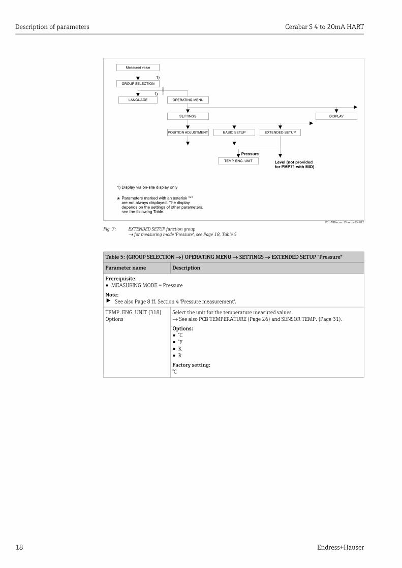
P01-MIDxxxxx-19-xx-xx-EN-012
Fig. 7: EXTENDED SETUP function groupfor measuring mode "Pressure", see Page 18, Table 5
1)
1)
*
LANGUAGE
Pressure
BASIC SETUP
DISPLAYSETTINGS
POSITION ADJUSTMENT
OPERATING MENU
GROUP SELECTION
Measured value
EXTENDED SETUP
TEMP. ENG. UNIT
1) Display via on-site display only
Parameters marked with an asterisk "*"are not always displayed. The displaydepends on the settings of other parameters,see the following Table.
Level (notfor PMP71 with MID)
provided
Table 5: (GROUP SELECTION ) OPERATING MENU SETTINGS EXTENDED SETUP "Pressure"
Parameter name Description
Prerequisite:• MEASURING MODE = Pressure
Note:‣ See also Page 8 ff, Section 4 "Pressure measurement".
TEMP. ENG. UNIT (318)Options
Select the unit for the temperature measured values. See also PCB TEMPERATURE (Page 26) and SENSOR TEMP. (Page 31).
Options:• °C• °F• K• R
Factory setting:°C

Cerabar S 4 to 20mA HART Description of parameters
Endress+Hauser 19
P01-xxxxxxxx-19-xx-xx-xx-093
Fig. 8: DISPLAY group
1)
1)
2)
DIGITS SETS
LANGUAGE
TOTALIZER SETUP
MENU DESCRIPTION
MAIN DATA FORMAT
ALTERNATE DATA
DISPLAY CONTRAST
LANGUAGE
DISPLAYSETTINGS
POSITION ADJUSTMENT
OPERATING MENU
GROUP SELECTION
Measured value
1) Display via on-site display only
2) Display via digital communication
Table 6: (GROUP SELECTION ) OPERATING MENU DISPLAY
Parameter name Description
MENU DESCRIPTOR (419)Options
Specify contents for the main line of the onsite display in the measuring mode. See also Operating Instructions BA00412P, Section "Onsite display".
Options:• Main measured value (PV)• Main measured value (%)• Pressure• Level• Tank content• Current• Temperature• Error number
The selection depends on the measuring mode chosen.
Factory setting:Main measured value (PV)
MAIN DATA FORMAT (688)Options
Specifies the number of places after the decimal point for the value displayed in the main line.See also Operating Instructions BA00412P, Section "Onsite display".
Options:• Auto• x.x• x.xx• x.xxx• x.xxxx• x.xxxxx
Factory setting:Auto
ALTERNATE DATA (423)Options
Switch on "Alternating display" mode.
In this display mode, the onsite display alternates between the following measured values depending on the measuring mode selected. – Pressure: primary value (PV), pressure, temperature and current
Options:• Off• On
Factory setting:Off

Description of parameters Cerabar S 4 to 20mA HART
20 Endress+Hauser
LANGUAGE Selection
Select the menu language for the onsite display.
• In the case of local operation, the LANGUAGE parameter is arranged directly under the GROUP SELECTION (menu path: GROUP SELECTION LANGUAGE, see also Page 11).
• Select the menu language for the operating program via the "Options" menu "Settings" "Language" tab "Tool Language" field.
Options:• Deutsch• English• Français• Italiano• Español• Nederlands• Chinese (CHS)• Japanese (JPN)
Factory setting:English
DISPLAY CONTRAST (339)Entry
Adjust contrast of onsite display.You specify the contrast of the display with a number. Changes are only accepted as single steps, i.e. to change the value from "8" to "4", you need to save four times. You can also adjust the contrast of the display by means of the keys on the electronic insert or at the device.See also Operating Instructions BA00412P, the section on operating keys function.
Input range:4...13, 4: contrast weaker (brighter), 13: contrast stronger (darker).
Factory setting:8
DIGITS SET (840)Display
This parameter is used to verify correct display of characters and digits on the user interface. If the characters and digits are correctly displayed, this parameter shows the string "0123456789.-".
Table 6: (GROUP SELECTION ) OPERATING MENU DISPLAY
Parameter name Description

Cerabar S 4 to 20mA HART Description of parameters
Endress+Hauser 21
P01-MIDxxxxx-19-xx-xx-EN-013
Fig. 9: Group OUTPUT
1)
1)
SET MIN. CURRENT
ASSIGN CURRENTLevel measuringmode only
ALT. CURR. OUTPUT
TOTALIZER SETUP
OUTPUT CURRENT
CURR. CHARACT.
OUTPUT FAIL MODE
SET MAX. ALARM
LANGUAGE
OUTPUTSETTINGS
POSITION ADJUSTMENT
OPERATING MENU
GROUP SELECTION
Measured value
1) Display via on-site display only
Table 7: (GROUP SELECTION ) OPERATING MENU OUTPUT
Parameter name Description
OUTPUT CURRENT (254)Display
Displays the current current value.

Description of parameters Cerabar S 4 to 20mA HART
22 Endress+Hauser
CURR. CHARACT.(694), (695), (696), (764)Options
Select curve of current output.
Options:
P01-xxxxxxxx-05-xx-xx-xx-009
Fig. 10: Illustration of current output curves
1 Linear: lower range value = 4 mA, upper range value = 20 mA2 Bi-linear: lower range value = 4 mA, center or zero = 20 mA,
upper range value = 4 mA3 Linear inverse: lower range value = 20 mA, upper range value = 4 mA4 Bi-linear inverse: lower range value = 20 mA, center or zero = 4 mA,
upper range value = 20 mALRV Lower Range ValueURV Upper Range ValueI Currentp Measured value (pressure)
The 3-digit ID number on the onsite display depends on the MEASURING MODE selected:– (694): MEASURING MODE "Pressure"
Factory setting:Linear
OUTPUT FAIL MODE (388)Entry
Select the current value in the event of an alarm.In the event of an alarm, the current assumes the current value specified with this parameter.
Options: • Max. alarm (110%): can be set between 21...23 mA• Hold meas. value: last measured value is kept.• Min. alarm (–10%): 3.6 mA
See also this table SET MAX. ALARM and Operating Instructions BA00412P, Section "Configuring current output for an alarm".
Factory setting:Max. alarm 110% (22 mA)
ALT.CURR.OUTPUT (597)Options
Set current output if sensor limits undershot or overshot.
Options: • Normal: the current output assumes the value set via the OUTPUT FAIL MODE
and SET MAX. ALARM parameters.• NAMUR:
– Lower sensor limit undershot (E120): Current output = 3.6 mA
– Upper sensor limit overshot (E115): current output assumes the value set via the SET MAX. ALARM parameter
Factory setting:Normal
Table 7: (GROUP SELECTION ) OPERATING MENU OUTPUT
Parameter name Description
LRV
➂
➁
➀
4 mA
0
20 mA
➁
➃ ➃
URVURV
I
p

Cerabar S 4 to 20mA HART Description of parameters
Endress+Hauser 23
SET MAX. ALARM (342)Entry
Enter current value for maximum alarm current.See also OUTPUT FAIL MODE.
Input range:21...23 mA
Factory setting:22 mA
SET MIN. CURRENT (343)Entry
Enter lower current limit.Some switching units do not accept current values lower than 4.0 mA.
Options: • 3.8 mA• 4.0 mA
Factory setting:3.8 mA
Table 7: (GROUP SELECTION ) OPERATING MENU OUTPUT
Parameter name Description

Description of parameters Cerabar S 4 to 20mA HART
24 Endress+Hauser
P01-xxxxxxxx-19-xx-xx-xx-095
Fig. 11: TRANSMITTER INFO groupFor the HART DATA function group, see Page 24, Table 8For the TRANSMITTER DATA function group, see Page 26, Table 9For the PROCESS CONNECTION function group, see Page 27, Table 10For the SENSOR DATA function group, see Page 29, Table 11
2)
2)
2)
2)
2)
2)
2)
2)
2)
2)
2)
2)
2)
2)
2)
2)
2)
2)
2)
2)
1)
1)
2)
2)
DIP STATUS
DIAPHRAGM SEAL +
DIAPHRAGM SEAL –
NR OF REMOTE SEAL
FILL FLUID
PCB TEMPERATURE
ALLOWED MIN. TEMP
ALLOWED MAX. TEMP
Tmax SENSOR
SENS H/WARE REV.
MOUNTING THREAD
REMOTE SEAL +
REMOTE SEAL –
DEVICE DESIGN.
HARDWARE REV.
SOFTWARE VERSION
CONFIG RECORDER
MAT. MEMBRANE
FILLING FLUID
Tmin SENSOR
NUTS MATERIAL
DRAIN VENT MAT.
DRAIN VENT POS.
THREAD
ADDITIONAL INFO. SEAL TYPE SENSOR MEAS. TYPE
BOLTS MATERIAL
DEVICE REVISION
ELECTR. SERIAL No
CUST. TAG NUMBER
LONG TAG NUMBER
PROC. CONN TYPE
MAT. PROC. CONN. +
MAT. PROC. CONN. –
PRESS. SENS LOLIM
PRESS: SENS HILIM
MINIMUM SPAN
HART DATA
BUS ADRESS
TRANSMITTER INFO
TRANSMITTER DATA
DEVICE SERIAL No
PROCESS CONNECTION
Pmax PROC. CONN.
SENSOR DATEN
SENSOR SER. No.
TOTALIZER SETUP
4TH VALUE IS
4 TH VALUE
SECONDARY VALUE
THIRD VALUE IS
THIRD VALUE
HART DATE
PRIMARY VALUE IS
PRIMARY VALUE
SECONDARY VAL. IS
HART MESSAGE
MANUFACTOR ID
PREAMBLE NUMBER
LANGUAGE
SETTINGS
POSITION ADJUSTMENT
OPERATING MENU
GROUP SELECTION
Measured value
DEVICE TYPE
1) Display via on-site display only
2) Display via digital communication
BURST MODE
BURST OPTION
Table 8: (GROUP SELECTION ) OPERATING MENU TRANSMITTER INFO HART DATA
Parameter name Description
BUS ADDRESS (345)Entry
Enter the address for the exchange of data with the HART protocol. (HART 5.0: range 0...15, HART 6.0: range 0...63)
Factory setting:0
DEVICE TYPE (802)Display
Displays the device identification number in decimal numerical format, here Cerabar S: 24
Prerequisite:• Cerabar S pressure transmitter
DEVICE REVISION (699)Display
Displays the device revision

Cerabar S 4 to 20mA HART Description of parameters
Endress+Hauser 25
BURST MODEOptions
Switch the burst mode on and off.
Options: • On• Off
Prerequisite:• Digital communication
BURST OPTIONEntry
Use this parameter to specify what command is sent to the master.
Prerequisite:• Digital communication
Factory setting:3 (HART command 3)
PREAMBLE NUMBER (036)Entry
Enter the number of preambles in the HART protocol. (Synchronization of the modem modules along a transmission path, each modem module could "swallow" a byte - at least 2 bytes must arrive.)
Input range:2...20
Factory setting:5
MANUFACTOR ID (432)Display
Displays the manufacturer number in a decimal numerical format.Here: 17 Endress+Hauser
HART MESSAGE (271)Entry
Enter a message (max. 32 alphanumeric characters). On command from the master, this message is sent via the HART protocol.
Factory setting:_ _ _ _ _ _ _ _ _ _ _ _ _ _ _ _ _ _ _ _ _ _ _ _ _ _ _ _ _ _ _ _ or as per order specifications
HART DATE (481)Entry
Enter the date of the last configuration change.
Factory setting:DD.MM.YY (date of final test)
PRIMARY VALUE ISDisplay
This parameter displays the following measured value depending on the measuring mode selected: – Measuring mode "Pressure": PRESSURE
See also PRIMARY VALUE.
Prerequisite:• Digital communication
PRIMARY VALUEDisplay
Display of primary value. See also PRIMARY VALUE IS.
Prerequisite:• Digital communication
SECONDARY VAL. IS Select second process value.
You can choose between the following process values depending on the measuring mode selected:– PRESSURE– CORRECTED PRESS.– SENSOR PRESSURE– SENSOR TEMP.– PCB TEMPERATURE– LEVEL BEFORE LIN– TANK CONTENT
Prerequisite:• Digital communication
SECONDARY VALUE Display second process value. See also SECONDARY VAL. IS.
Prerequisite:• Digital communication
Table 8: (GROUP SELECTION ) OPERATING MENU TRANSMITTER INFO HART DATA
Parameter name Description

Description of parameters Cerabar S 4 to 20mA HART
26 Endress+Hauser
THIRD VALUE IS Select third process value. See also . SECONDARY VAL. IS.
Prerequisite:• Digital communication
THIRD VALUE Display third process value. See also SECONDARY VAL. IS.
Prerequisite:• Digital communication
4TH VALUE IS Select fourth process value. See also . SECONDARY VAL. IS.
Prerequisite:• Digital communication
4TH VALUE Display fourth process value. See also SECONDARY VAL. IS.
Prerequisite:• Digital communication
Table 9: (GROUP SELECTION ) OPERATING MENU TRANSMITTER INFO TRANSMITTER DATA
Parameter name Description
DEVICE SERIAL No (354)Display
Displays the serial number of the device (11 alphanumeric characters).
ELECTR. SERIAL No (386)Display
Displays the serial number of the main electronics (11 alphanumeric characters).
CUST. TAG NUMBER (055)Entry
Enter device tag e.g. TAG number (max. 8 alphanumeric characters).
Factory setting:_ _ _ _ _ _ _ _ or as per order specifications
LONG TAG NUMBER (305)Entry
Enter device tag e.g. TAG number (max. 32 alphanumeric characters).
Factory setting:_ _ _ _ _ _ _ _ _ _ _ _ _ _ _ _ _ _ _ _ _ _ _ _ _ _ _ _ _ _ _ _ or as per order specifications
ADDITIONAL INFO. (272)Entry
Enter the tag description (max. 16 alphanumeric characters).
Factory setting:_ _ _ _ _ _ _ _ _ _ _ _ _ _ _ _ or as per order specifications
DEVICE DESIGN. (350)Display
Displays the device designation and order code.
HARDWARE REV. (266)Display
Displays the revision number of the main electronicse.g.: V02.00
SOFTWARE VERSION (264)Display
Displays the software versionV02.10.54
CONFIG RECORDER (352)Display
Displays the configuration counter.This counter is increased by one with each change to a parameter or group. The counter counts to 65535 and then starts again at zero. Changes in the parameters of the DISPLAY function group do not increase the counter.
PCB TEMPERATURE (357)Display
Displays the measured temperature of the main electronics.
ALLOWED MIN. TEMP (358)Display
Displays the lower temperature limit of the main electronics.
ALLOWED MAX. TEMP (359)Display
Displays the upper temperature limit of the main electronics.
Table 8: (GROUP SELECTION ) OPERATING MENU TRANSMITTER INFO HART DATA
Parameter name Description

Cerabar S 4 to 20mA HART Description of parameters
Endress+Hauser 27
DIP STATUS (363)Display
Displays the status of DIP switch 1 on the electronic insert.You can lock or unlock parameters relevant to the measured value with DIP switch 1. If operation is locked by means of the INSERT PIN No. parameter, you can only unlock operation again by means of this parameter. (INSERT PIN NO, see Page 33.)See also Operating Instructions BA00412P, "Locking/unlocking operation".
Display: • On (locking switched on)• Off (locking switched off)
Factory setting:Off (locking switched off)
Table 10: (GROUP SELECTION ) OPERATING MENU TRANSMITTER INFO PROCESS CONNECTION
Parameter name Description
Pmax PROC. CONN. (570)Entry
For entering and displaying the maximum permitted pressure of the process connection.
Factory setting:as per nameplate data (see also Operating Instructions BA00412P, Section "Nameplate")
PROC. CONN. TYPE (482)Options
For selecting and displaying the process connection type.
Options: • Not used• Unknown• Special• Oval flange• Thread female• Thread male• Flange• Remote seal
MAT. PROC. CONN. + (360)Options
For selecting and displaying the material of the process connection (P+). See also parameter description for MAT. PROC. CONN. -
Options: • Not used• Unknown• Special• Steel• 304 st. steel• 316 st. steel• Alloy C• Monel• Tantalum• Titanium• PTFE (Teflon)• 316L st. steel• PVC• Inconel• PVDF• ECTFE
Factory setting:As per order specifications
Table 9: (GROUP SELECTION ) OPERATING MENU TRANSMITTER INFO TRANSMITTER DATA
Parameter name Description

Description of parameters Cerabar S 4 to 20mA HART
28 Endress+Hauser
SEAL TYPE (362)Options
For selecting and displaying the material of the process seal.
Options: • Not used• Unknown• Special• FKM Viton• NBR• EPDM• Urethane• IIR• Kalrez• FKM Viton oxyg• CR• MVQ• PTFE glass• PTFE graphite• PTFE oxygen• Copper• Copper f. oxygen
Factory setting:As per order specifications
BOLTS MATERIAL For selecting and displaying the material of the bolts.
Prerequisite:• Digital communication
NUTS MATERIAL For selecting and displaying the material of the nuts.
Prerequisite:• Digital communication
DRAIN VENT MAT. For selecting and displaying the material of the vent valves.
Prerequisite:• Digital communication
DRAIN VENT POS. For selecting and displaying the position of the vent valves.
Prerequisite:• Digital communication
THREAD PROCESS For selecting and displaying the process connection thread.
Prerequisite:• Digital communication
MOUNTING THREAD For selecting and displaying the ways of securing the device.
Prerequisite:• Digital communication
REMOTE SEAL + For selecting and displaying the diaphragm seal type on the positive side.
Prerequisite:• Digital communication
REMOTE SEAL - For selecting and displaying the diaphragm seal type on the negative side.
Prerequisite:• Digital communication
DIAPHRAG. MAT. + For selecting and displaying the diaphragm material on the positive side
Prerequisite:• Digital communication
DIAPHRAG. MAT. - For selecting and displaying the diaphragm material on the negative side.
Prerequisite:• Digital communication
NR OF REMOTE SE For selecting and displaying the number of diaphragm seals.
Prerequisite:• Digital communication
Table 10: (GROUP SELECTION ) OPERATING MENU TRANSMITTER INFO PROCESS CONNECTION
Parameter name Description

Cerabar S 4 to 20mA HART Description of parameters
Endress+Hauser 29
FILL FLUID For selecting and displaying the diaphragm seal fill fluid.
Prerequisite:• Digital communication
Table 11: (GROUP SELECTION ) OPERATING MENU TRANSMITTER INFO SENSOR DATA (all measuring modes)
Parameter name Description
SENSOR SER. No. (250)Display
Displays the serial number of the sensor (11 alphanumeric characters).
PRESS. SENS LOLIM (484)Display
Displays the lower measuring limit of the sensor.
PRESS. SENS HILIM (485)Display
Displays the upper measuring limit of the sensor.
MINIMUM SPAN (591)Display
Displays the smallest possible span.
SENSOR MEAS.TYPE (581)Display
Displays the sensor type.
• Cerabar S with absolute pressure sensor = Absolute
MAT. MEMBRANE (365)Display
Displays the material of the process isolating diaphragm.
Factory setting:as per version in order code See Technical Information for Cerabar S TI00383P, Section "Ordering information".
FILLING FLUID (366)Display
Displays the filling fluid.
Tmin SENSOR (368)Display
Displays the lower nominal temperature limit of the sensor.
Tmax SENSOR (369)Display
Displays the upper nominal temperature limit of the sensor.
SENS H/WARE REV (487)Display
Displays the revision number of the sensor hardware.e.g.: 1
Table 10: (GROUP SELECTION ) OPERATING MENU TRANSMITTER INFO PROCESS CONNECTION
Parameter name Description

Description of parameters Cerabar S 4 to 20mA HART
30 Endress+Hauser
P01-MIDxxxxx-19-xx-xx-EN-014
Fig. 12: PROCESSINFO groupFor function group PROCESS VALUES, measuring mode "Pressure", see Page 30, Table 12
2)
1)
1)
PRESSURE
CORRECTED PRESS.
SENSOR PRESSURE
SENSOR TEMP.
MEAS. VAL. TREND
MEASURED VALUE
Pressure
PROCESS VALUE
PROCESS INFO
TOTALIZER SETUP
LANGUAGE
SETTINGS
POSITION ADJUSTMENT
OPERATING MENU
GROUP SELECTION
Measured value
1) Display via on-site display only
2) Display via digital communication
Level (notfor PMP71 with MID)
provided
Table 12: (GROUP SELECTION ) OPERATING MENU PROCESSINFO PROCESS VALUES "Pressure"
Parameter name Description
Prerequisite:• MEASURING MODE = Pressure
MEASURED VALUE (679) Displays the measured valueIn the "Pressure" measuring mode, this value corresponds to the PRESSURE parameter.
Prerequisite:• Digital communication
Onsite operation:• In the case of local operation, the MEASURED VALUE parameter is displayed on
the top level.

Cerabar S 4 to 20mA HART Description of parameters
Endress+Hauser 31
PRESSURE (301)Display
Displays the measured pressure after sensor recalibration, position adjustment and damping. This value corresponds to the MEASURED VALUE parameter in the "Pressure" measuring mode.
P01-MIDxxxxx-05-xx-xx-EN-001
CORRECTED PRESS. (434)Display
Displays the measured pressure after sensor trim and position adjustment and before damping. See also PRESSURE diagram.
SENSOR PRESSURE (584)Display
Displays the measured pressure before sensor trim, position adjustment and damping. See also PRESSURE diagram.
SENSOR TEMP. (367)Display
Displays the temperature currently measured in the sensor. This can deviate from the process temperature.
MEAS. VAL. TREND (378)Display
Displays the trend of the pressure measured value.Possibilities: increasing, decreasing, constant
Table 12: (GROUP SELECTION ) OPERATING MENU PROCESSINFO PROCESS VALUES "Pressure"
Parameter name Description
P ISensorCurrentoutputPressure
PRESSURE
Damping
CORRECTEDPRESS.
Positionadjust-ment
Sensortrim
SENSORPRESSURE

Description of parameters Cerabar S 4 to 20mA HART
32 Endress+Hauser
P01-MIDxxxxx-19-xx-xx-EN-015
Fig. 13: OPERATING and DIAGNOSTICS groupFor the OPERATING group, see Page 32, Table 13For the SIMULATION MODE function group, see Page 34, Table 14For the MESSAGES function group, see Page 35, Table 15 For the USER LIMITS function group, see Page 36, Table 16
*
I
J
*
I
J J J J J
1)
1)
2)
*
*
none Pressure Tank content Current Alarm Warning
LANGUAGE
SETTINGS
POSITION ADJUSTMENT
OPERATING MENU
GROUP SELECTION
Measured value
SIM. PRESSURE SIM. TANK CONT. SIM. CURRENT SIM. ERROR NO.
OPERATION
ENTER RESET CODE
OPERATING HOURS
INSERT PIN NO
DIAGNOSTICS
SIMULATION
SIMULATION MODE
MESSAGES
RESET ALL ALARMS
SELECT ALARMTYPE
ALARM DELAY
ALARM DISPL. TIME
ALARM STATUS
LAST DIAG. CODE
ACK. ALARM MODE
ACK. ALARM
Pmin ALARM WINDOW
Pmax ALARM WINDOW
Tmin ALARM WINDOW
Tmax ALARM WINDOW
USER LIMITS
HistoROM AVAIL.
HistoROM CONTROL ERROR No.
Parameters marked with an asterisk "*"are not always displayed. The displaydepends on the settings of other parameters,see the following Table.
1) Display via on-site display only
2) Display via digital communicationDOWNLOAD SELECT.
Table 13: (GROUP SELECTION ) OPERATING MENU OPERATING
Parameter name Description
ENTER RESET CODE (047)Entry
Reset parameters completely or partially to factory values or delivery status.See also Operating Instructions BA00412P, Section "Factory setting (reset)".
Factory setting:0
OPERATING HOURS (409)Display
Displays the hours of operation. This parameter cannot be reset.

Cerabar S 4 to 20mA HART Description of parameters
Endress+Hauser 33
INSERT PIN NO (048)Entry
For entering a code to lock or unlock operation.
• The symbol on the onsite display indicates that operation is locked. Parameters which refer to how the display appears, e.g. LANGUAGE and DISPLAY CONTRAST can still be altered.
• If operation is locked by means of the DIP switch, you can only unlock operation again by means of the DIP switch. If operation is locked by means of the onsite display or remote operation e.g. FieldCare, you can unlock operation again either by means of the onsite display or remote operation.
See also Operating Instructions BA00412P, "Locking/unlocking operation".
Options: • Lock: enter a number between 0 and 9999 that is 100.• Unlock: enter the number 100.
Factory setting:100
HistoROM AVAIL. (831)Display
Indicates whether the optional HistoROM®/M-DAT memory module is connected to the electronic insert.See also Operating Instructions BA00412P, Section "HistoROM®/M-DAT (optional)".
Options:• Yes (HistoROM®/M-DAT is attached to the electronic insert)• No (HistoROM®/M-DAT is not attached to the electronic insert)
DOWNLOAD SELECT (014)Options
Select download function from HistoROM to device. The option selected has no effect on an upload from the device to the HistoROM.
Prerequisite:• A HistoROM®/M-DAT is attached to the electronic insert
(HistoROM AVAIL. = Yes)
Options:• Configuration copy: With this option, all parameters apart from the
TRANSMITTER SERIAL No, DEVICE DESIGN., CUST. TAG NUMBER, LONG TAG NUMBER, ADDITIONAL INFO., BUS ADDRESS and the parameters of the POSITION ADJUSTMENT and PROCESS CONNECTION group are overwritten.
• Device replacement: With this option, all parameters except for TRANSMITTER SERIAL No, DEVICE DESIGNATION and the parameters of the POSITION ADJUSTMENT and PROCESS CONNECTION group are overwritten.
• Electronics replace: With this option, all parameters except for the parameters of the POSITION ADJUSTMENT group are overwritten.
Factory setting:Configuration copy (if HistoROM®/M-DAT is attached to the electronic insert)
HistoROM CONTROL (832)Options
For selecting the direction for copying the data.See also Operating Instructions BA00412P, Section "HistoROM®/M-DAT (optional)".
Prerequisite:• A HistoROM®/M-DAT is attached to the electronic insert
(HistoROM AVAIL. = Yes)
Options:• Abort• HistoROM Device• Device HistoROM
Factory setting:Abort (if HistoROM®/M-DAT is attached to the electronic insert)
Table 13: (GROUP SELECTION ) OPERATING MENU OPERATING
Parameter name Description

Description of parameters Cerabar S 4 to 20mA HART
34 Endress+Hauser
Table 14: (GROUP SELECTION ) OPERATING MENU DIAGNOSTICS SIMULATION MODE
Parameter name Description
SIMULATION MODE (413)Options
Switch on simulation and select simulation type. Any simulation running is switched off if the measuring mode or level type is changed.
Options: • None • Pressure, see also this table, parameter description for SIM. PRESSURE.• Tank content, see also this table, parameter description for SIM. TANK CONT.• Current, see also this table, parameter description for SIM. CURRENT• Alarm/warning, , see also this table, parameter description for SIM. ERROR
NO.
P01-MIDxxxxx-05-xx-xx-EN-003
Factory setting:None
SIM. PRESSURE (414)Entry
Enter simulation value. See also SIMULATION MODE.
Prerequisite:• SIMULATION MODE = Pressure
Factory setting:Current pressure measured value
SIM. CURRENT (270)Entry
Enter simulation value. See also SIMULATION MODE.
Prerequisite:• SIMULATION MODE = Current value
Factory setting:Current current value
SIM. ERROR NO. (476)Entry
Enter message number.See also SIMULATION MODE.See also these Operating Instructions, Section 6.1 "Messages", "Code" table column.
Prerequisite:• SIMULATION MODE = Alarm/warning
Factory setting:613 (simulation active)
P I
Simulation value pressure
Simulation valuecurrent
SensorCurrentoutputPressureDamping
Positionadjust-ment
Sensortrim

Cerabar S 4 to 20mA HART Description of parameters
Endress+Hauser 35
Table 15: (GROUP SELECTION ) OPERATING MENU DIAGNOSTICS MESSAGES
Parameter name Description
ALARM STATUS (046)Display
Displays the current messages present. See also these Operating Instructions, Section 6.1 "Messages" and Section "Confirming messages".
Onsite display• The measured value display shows the message with the highest priority.• The ALARM STATUS parameter shows all the messages in descending order of
priority. You can scroll through all the messages present with the O or S key.
Operating program• The "Status" field and the ALARM STATUS parameter show the message with the
highest priority.
LAST DIAG. CODE (564)Display
Displays the last messages that occurred and were eliminated.
• Onsite display: you can scroll through the last 15 messages with the O or S key.• Digital communication: the last message is displayed.• Use the RESET ALL ALARMS parameter to delete the messages listed in the
LAST DIAG. CODE parameter.
ACK. ALARM MODE (401)Options
Switch on acknowledge alarm mode. See also ACK. ALARM.
Options: • On• Off
Factory setting:Off
ACK. ALARM (500)Options
Acknowledge alarm.
Prerequisite:• ACK. ALARM MODE = On
Options: • Abort• Confirm
The cause of the alarm must be eliminated, the message must be acknowledged via the ACK. ALARM parameter and, where applicable, the ALARM DISPL. TIME (Page 36) has to have elapsed before the device starts measuring again following an alarm.See also these Operating Instructions, Section 6.3 "Confirming messages".
Factory setting:Abort
RESET ALL ALARMS (603)Options
Use this parameter to reset all the messages of the LAST DIAG. CODE parameter.
Options: • Abort• Confirm
Factory setting:Abort
ERROR No.Entry
For "Error"-type messages, you can decide whether the device should behave as in the event of an alarm (A) or as in the event of a warning (W). Enter the corresponding message number for this parameter. See also SELECT ALARMTYPE.See also these Operating Instructions, Section 6.1 "Messages" and Section 6.2 "Response of outputs to errors".
Prerequisite:• Digital communication

Description of parameters Cerabar S 4 to 20mA HART
36 Endress+Hauser
SELECT ALARMTYPE(595) – Entry(600) – Selection
For "Error"-type messages, you can decide whether the device should behave as in the event of an alarm (A) or as in the event of a warning (W). See also ERROR No.See also these Operating Instructions, Section 6.2 "Response of outputs to errors".
Options: • Alarm (A): output current assumes a defined value.• Warning (W): device continues measuring
Onsite operation:
1. Enter the corresponding message number for ERROR No. field.
2. Select "Alarm" or "Warning" option.
Digital communication
1. Enter the corresponding message number via the ERROR No. parameter.
2. Use the SELECT ALARMTYPE parameter to select the "Alarm" or "Warning" option.
ALARM DELAY (336)Entry
Enter the alarm response time for all "Error"-type messages.
There is no alarm if the cause of the error is eliminated within the alarm delay time.
Input range:0...100 s
Factory setting:0.0 s
ALARM DISPL. TIME (480)Entry
Enter the alarm delay time for all "Error"-type messages. Once the cause of the error is rectified, the alarm display time starts running.
The following applies if the setting for ACK. ALARM MODE = On If an alarm appears and the alarm display time elapses before the alarm has been acknowledged, the message will be cleared once it has been acknowledged.See also these Operating Instructions, Section 6.3 "Confirming messages".
Input range:0 to 999.9 s
Factory setting:0.0 s
Table 16: (GROUP SELECTION ) OPERATING MODE DIAGNOSTICS USER LIMITS
Parameter name Description
Pmin ALARM WINDOW (332)Entry
Customer-specific process monitoring – enter lower pressure limit.You can use the SELECT ALARMTYPE parameter to enter how the device responds if the operating pressure undershoots the specified value. See also these Operating Instructions, Section 6.1 "Messages", Table, code E730 and Section 6.2 "Response of outputs to errors".
Factory setting:Low sensor limit •1.1 (For the low sensor limit, see PRESS. SENS LOLIM.)
Pmax ALARM WINDOW (333)Entry
Customer-specific process monitoring – enter upper pressure limit.You can use the SELECT ALARMTYPE parameter to enter how the device responds if the operating pressure undershoots the specified value. See also these Operating Instructions, Section 6.1 "Messages", Table, code E731 and Section 6.2 "Response of outputs to errors".
Factory setting:High sensor limit • 1.1 (For the high sensor limit, see PRESS. SENS HILIM.)
Table 15: (GROUP SELECTION ) OPERATING MENU DIAGNOSTICS MESSAGES
Parameter name Description

Cerabar S 4 to 20mA HART Description of parameters
Endress+Hauser 37
P01-MIDxxxxx-19-xx-xx-EN-016
Fig. 14: SYSTEM 2 group
Tmin ALARM WINDOW (334)Entry
Customer-specific process monitoring – enter lower temperature limit.You can use the SELECT ALARMTYPE parameter to enter how the device responds if the operating pressure undershoots the specified value. See also these Operating Instructions, Section 6.1 "Messages" Table, code E732 and Section 6.2 "Response of outputs to errors".
Factory setting:Lower sensor temperature application limit – 10 K (For the lower temperature application limit, see Tmin SENSOR)
Tmax ALARM WINDOW (335)Entry
Customer-specific process monitoring – enter upper temperature limit.You can use the SELECT ALARMTYPE parameter to enter how the device responds if the operating pressure undershoots the specified value. See also these Operating Instructions, Section 6.1 "Messages" Table, code E733 and Section 6.2 "Response of outputs to errors".
Factory setting:Upper sensor temperature application limit +10 K (For the upper temperature application limit, see Tmax SENSOR)
Table 16: (GROUP SELECTION ) OPERATING MODE DIAGNOSTICS USER LIMITS
Parameter name Description
1)
1)
SERVICE
CURR. TRIM 4mA
CURR. TRIM 20mA
OFFSET 4mA TRIM
OFFSET 20mA TRIM
SYSTEM 2
LANGUAGE
SETTINGS
POSITION ADJUSTMENT
OPERATING MENU
GROUP SELECTION
Measured value
1) Display via on-site display only

Description of parameters Cerabar S 4 to 20mA HART
38 Endress+Hauser
Table 17: (GROUP SELECTION ) OPERATING MENU SERVICE SYSTEM 2
Parameter name Description
CURR. TRIM 4mA (045)Entry
Enter the current value for the lower point (4 mA) of the current linear regression line.You can adapt the current output to the transmission conditions with this parameter and "CURR. TRIM 20mA".
Perform the current trim for the lower point as follows:
1. Select the SIMULATION MODE group. (Menu path: (GROUP SELECTION) OPERATING MENU DIAGNOSTICS SIMULATION MODE)
2. Select the "Current" option via the SIMULATION MODE parameter.
3. Enter "4 mA" for the SIM. CURRENT parameter.
4. Select the SYSTEM 2 group. (Menu path: (GROUP SELECTION) OPERATING MENU SERVICE)
5. Enter the current value measured with the switching unit in the "CURR. TRIM 4mA" parameter.
Input range:Measured current ±0.2 mA
Factory setting:4 mA
CURR. TRIM 20mA (042)Entry
Enter the current value for the upper point (20 mA) of the current linear regression line.You can adapt the current output to the transmission conditions with this parameter and "CURR. TRIM 4mA".
Perform the current trim for the upper point as follows:
1. Select the SIMULATION MODE group. (Menu path: (GROUP SELECTION) OPERATING MENU DIAGNOSTICS SIMULATION MODE)
2. Select the "Current" option via the SIMULATION MODE parameter.
3. Enter "20 mA" for the SIM. CURRENT parameter.
4. Select the SYSTEM 2 group. (Menu path: (GROUP SELECTION) OPERATING MENU SERVICE)
5. Enter the current value measured with the switching unit in the "CURR. TRIM 20mA" parameter.
Input range:Measured current ±0.2 mA
Factory setting:20 mA
OFFSET 4mA TRIM (043)Display
Displays the difference between 4 mA and the value entered for the "CURR. TRIM 4mA" parameter.
Factory setting:0
OFFSET 20mA TRIM (044)Display
Displays the difference between 20 mA and the value entered for the "CURR TRIM 20mA" parameter.
Factory setting:0

Cerabar S 4 to 20mA HART Troubleshooting
Endress+Hauser 39
6 Troubleshooting
6.1 MessagesThe following table lists all the possible messages that can occur. The device makes a distinction between the error types "Alarm", "Warning" and "Error". You may specify whether the device should react as if for an "Alarm" or "Warning" for "Error" messages. See "Error type/NA 64" column and parameter description for ERROR No. and SELECT ALARMTYPE (Page 36).
In addition, the "Error type/NA 64" column classifies the messages in accordance with NAMUR Recommendation NA 64: • Break down: indicated with "B"• Maintenance need: indicated with "C" (check request)• Function check: indicated with "I" (in service)
Error message display on the onsite display:• The measured value display shows the message with the highest priority. See the
"Priority" column.• The ALARM STATUS parameter (Page 35) shows all the messages in descending order
of priority. You can scroll through all the messages present with the S key or O key.
Message display via digital communication:• The ALARM STATUS parameter (Page 35) shows the message with the highest
priority. See the "Priority" column.
• If the device detects a defect in the onsite display during initialization, special error messages are generated. For the error messages, see Page 45, Section 6.1.1 "Onsite display error messages".
• For support and further information, please contact Endress+Hauser Service.
Code Error type/NA 64
Message/description Cause Measure Priority
101 (A101) AlarmB
B>Sensor electronic EEPROM error
– Electromagnetic effects are greater than specifications in the technical data. See Technical Information TI00383P. This message normally only appears briefly.
– Wait a few minutes.– Restart the device. Perform reset
(Code 62).– Block off electromagnetic effects
or eliminate source of disturbance.
17
– Sensor defective. – Replace sensor.
106 (W106)
WarningC
C>Downloading - please wait – Downloading. – Wait for download to complete. 52
110 (A110) AlarmB
B>Checksum error in EEPROM: configuration segment
– The supply voltage is disconnected when writing.
– Reestablish supply voltage. Perform reset (Code 7864) if necessary. Carry out calibration again.
6
– Electromagnetic effects are greater than specifications in the technical data. See Technical Information TI00383P.
– Block off electromagnetic effects or eliminate sources of disturbance.
– Main electronics defective. – Replace main electronics.
113 (A113) AlarmB
B>ROM failure in transmitter electronic
– Main electronics defective. – Replace main electronics. 1

Troubleshooting Cerabar S 4 to 20mA HART
40 Endress+Hauser
115 (E115) ErrorBFactory setting: Warning
B>Sensor overpressure – Overpressure present. – Reduce pressure until message disappears.
29
– Sensor defective. – Replace sensor.
116 (W116)
WarningC
C>Download error, repeat download
– The file is defective. – Use another file. 36
– During the download, the data are not correctly transmitted to the processor, e.g. because of open cable connections, spikes (ripple) on the supply voltage or electromagnetic effects.
– Check cable connection PC – transmitter.
– Block off electromagnetic effects or eliminate sources of disturbance.
– Perform reset (Code 7864) and carry out calibration again.
– Repeat download.
120 (E120) ErrorBFactory setting: Warning
B>Sensor low pressure – Pressure too low. – Increase pressure until message disappears.
30
– Sensor defective. – Replace sensor.
121 (A121) AlarmB
B>Checksum error in factory segment of EEPROM
– Main electronics defective. – Replace main electronics. 5
122 (A122) AlarmB
B>Sensor not connected – Cable connection sensor –main electronics disconnected.
– Check cable connection and repair if necessary.
13
– Electromagnetic effects are greater than specifications in the technical data. See Technical Information TI00383P.
– Block off electromagnetic effects or eliminate source of disturbance.
– Main electronics defective. – Replace main electronics.
– Sensor defective. – Replace sensor.
130 (A130) AlarmB
B>EEPROM is defective. – Main electronics defective. – Replace main electronics. 10
131 (A131) AlarmB
B>Checksum error in EEPROM: min/max segment
– Main electronics defective. – Replace main electronics. 9
132 (A132) AlarmB
B>Checksum error in totalizer EEPROM
– Main electronics defective. – Replace main electronics. 7
133 (A133) AlarmB
B>Checksum error in History EEPROM
– An error occurred when writing. – Perform reset (Code 7864) and carry out calibration again.
8
– Main electronics defective. – Replace main electronics.
602 (W602)
WarningC
C>Linearization curve not monotone
– The linearization table is not monotonic increasing or decreasing.
– Add to or correct linearization table. Then accept linearization table again.
57
Code Error type/NA 64
Message/description Cause Measure Priority

Cerabar S 4 to 20mA HART Troubleshooting
Endress+Hauser 41
604 (W604)
WarningC
C>Linearization table not valid. Less than 2 points or points too close
– The linearization table consists of less than 2 points.
– Add to linearization table. If necessary, confirm linearization table again.
58
– At least 2 points in the linearization table are too close together. A minimum gap of 0.5 % of the span must be maintained between two points.Spans for the "Pressure linearized" option: HYDR. PRESS MAX. – HYDR. PRESS MIN.; TANK CONTENT MAX. – TANKCONTENT MIN.Spans for the "Height linearized" option: LEVEL MAX – LEVEL MIN; TANK CONTENT MAX. – TANK CONTENT MIN.
– Correct linearization table and accept again.
613 (W613)
WarningI
I>Simulation is active – Simulation is switched on, i.e. the device is not measuring at present.
– Switch off simulation. 60
620 (E620) ErrorCFactory setting: Warning
C>Current output out of range The current is outside the permitted range 3.8 to 20.5 mA.
– The pressure applied is outside the set measuring range (but within the sensor range).
– Check pressure applied, reconfigure measuring range if necessary. See also these Operating Instructions Section 4.
– Perform reset (Code 7864) and carry out calibration again.
49
– Loose connection at sensor cable – Wait a short period of time and tighten the connection, or avoid loose connection.
700 (W700)
WarningC
C>Last configuration not stored – An error occurred when writing or reading configuration data or the power supply was disconnected.
– Perform reset (Code 7864) and carry out calibration again.
54
– Main electronics defective. – Replace main electronics.
701 (W701)
WarningC
C>Measuring chain config. exceeds sensor range
– The calibration carried out would result in the sensor nominal operating range being undershot or overshot.
– Carry out calibration again. 51
702 (W702)
WarningC
C>HistoROM data not consistent.
– Data were not written correctly to the HistoROM, e.g. if the HistoROM was detached during the writing process.
– Repeat upload.– Perform reset (Code 7864) and
carry out calibration again.
55
– HistoROM does not have any data.
– Copy suitable data to the HistoROM. (See also Operating Instructions BA00412P, Section "Copying configuration data".)
703 (A703) AlarmB
B>Measurement error – Fault in the main electronics. – Briefly disconnect device from the power supply.
22
– Main electronics defective. – Replace main electronics.
704 (A704) AlarmB
B>Measurement error – Fault in the main electronics. – Briefly disconnect device from the power supply.
12
– Main electronics defective. – Replace main electronics.
705 (A705) AlarmB
B>Measurement error – Fault in the main electronics. – Briefly disconnect device from the power supply.
21
– Main electronics defective. – Replace main electronics.
Code Error type/NA 64
Message/description Cause Measure Priority

Troubleshooting Cerabar S 4 to 20mA HART
42 Endress+Hauser
706 (W706)
WarningC
C>Configuration in HistoROM and device not identical
– Configuration (parameters) in the HistoROM and in the device is not identical.
– Copy data from the device to the HistoROM.
– Copy data from the HistoROM to the device. The message remains if the HistoROM and the device have different software versions. The message goes out if you copy the data from the device to the HistoROM.
– Device reset codes such as 7864 do not have any effect on the HistoROM. That means that if you perform a reset, the configurations in the HistoROM and in the device may not be the same.
See also Operating Instructions BA00412P, Section "Copying configuration data".
59
707 (A707) AlarmB
B>X-VAL. of lin. table out of edit limits.
– At least one X-VALUE in the linearization table is either below the value for HYDR. PRESS MIN. or MIN. LEVEL or above the value for HYDR. PRESS. MAX. or LEVEL MAX
– Carry out calibration again. (See also these Operating Instructions, Section 5.)
38
710 (W710)
WarningC
B>Set span too small. Not allowed.
– Values for calibration (e.g. lower range value and upper range value) are too close together.
– Adjust calibration to suit sensor. ( See also Page 29, parameter description for MINIMUM SPAN.)
51
– The sensor was replaced and the customer-specific configuration does not suit the sensor.
– Adjust calibration to suit sensor.– Replace sensor with a suitable
sensor.
– Unsuitable download carried out. – Check configuration and perform download again.
711 (A711) AlarmB
B>LRV or URV out of edit limits – Lower range value and/or upper range value undershoot or overshoot the sensor range limits.
– Reconfigure lower range value and/or upper range value to suit the sensor. Pay attention to position factor.
37
– The sensor was replaced and the customer-specific configuration does not suit the sensor.
– Reconfigure lower range value and/or upper range value to suit the sensor. Pay attention to position factor.
– Replace sensor with a suitable sensor.
– Unsuitable download carried out. – Check configuration and perform download again.
713 (A713) AlarmB
B>100% POINT level out of edit limits
– The sensor was replaced. – Carry out calibration again. 39
715 (E715) ErrorCFactory setting: Warning
C>Sensor over temperature – The temperature measured in the sensor is greater than the upper nominal temperature of the sensor. (See also these Operating Instructions, parameter description for Tmax SENSOR.)
– Reduce process temperature/ambient temperature.
32
– Unsuitable download carried out. – Check configuration and perform download again.
716 (E716) ErrorBFactory setting: Alarm
B>Process isolating diaphragm broken
– Sensor defective. – Replace sensor. 24
Code Error type/NA 64
Message/description Cause Measure Priority

Cerabar S 4 to 20mA HART Troubleshooting
Endress+Hauser 43
717 (E717) ErrorCFactory setting: Warning
C>Transmitter over temperature
– The temperature measured in the electronics is greater than the upper nominal temperature of the electronics (+88 °C).
– Reduce ambient temperature. 34
– Unsuitable download carried out. – Check configuration and perform download again.
718 (E718) ErrorCFactory setting: Warning
C>Transmitter under temperature
– The temperature measured in the electronics is smaller than the lower nominal temperature of the electronics (–43 °C).
– Increase ambient temperature. Insulate device if necessary.
35
– Unsuitable download carried out. – Check configuration and perform download again.
720 (E720) ErrorCFactory setting: Warning
C>Sensor under temperature – The temperature measured in the sensor is smaller than the lower nominal temperature of the sensor. ( See also Page 29, parameter description for Tmin SENSOR.)
– Increase process temperature/ambient temperature.
33
– Unsuitable download carried out. – Check configuration and perform download again.
– Loose connection at sensor cable – Wait a short period of time and tighten the connection, or avoid loose connection.
721 (A721) AlarmB
B>ZERO POSITION level out of edit limits
– LEVEL MIN or LEVEL MAX has been changed.
– Perform reset (Code 2710) and carry out calibration again.
41
722 (A722) AlarmB
B>EMPTY CALIB. or FULL CALIB. out of edit limits
– LEVEL MIN or LEVEL MAX has been changed.
– Perform reset (Code 2710) and carry out calibration again.
42
725 (A725) AlarmB
B>Sensor connection error, cycle disturbance
– Electromagnetic effects are greater than specifications in the technical data. See Technical Information TI00383P.
– Block off electromagnetic effects or eliminate source of disturbance.
25
– Sensor or main electronics defective.
– Replace sensor or main electronics.
726 (E726) ErrorCFactory setting: Warning
C>Sensor temperature error - overrange
– Electromagnetic effects are greater than specifications in the technical data. See Technical Information TI00383P.
– Block off electromagnetic effects or eliminate source of disturbance.
31
– Process temperature is outside permitted range.
– Check temperature present, reduce or increase if necessary.
– Sensor defective. – If the process temperature is within the permitted range, replace sensor.
727 (E727) ErrorBFactory setting: Warning
B>Sensor pressure error - overrange
– Electromagnetic effects are greater than specifications in the technical data. See Technical Information TI00383P.
– Block off electromagnetic effects or eliminate source of disturbance.
28
– Pressure is outside permitted range.
– Check pressure present, reduce or increase if necessary.
– Sensor defective. – If the pressure is within the permitted range, replace sensor.
Code Error type/NA 64
Message/description Cause Measure Priority

Troubleshooting Cerabar S 4 to 20mA HART
44 Endress+Hauser
728 (A728) AlarmB
B>RAM error – Fault in the main electronics. – Briefly disconnect device from the power supply.
2
– Main electronics defective. – Replace main electronics.
729 (A729) AlarmB
B>RAM error – Fault in the main electronics. – Briefly disconnect device from the power supply.
3
– Main electronics defective. – Replace main electronics.
730 (E730) ErrorCFactory setting: Warning
C>LRV user limits exceeded – Pressure measured value has undershot the value specified for the Pmin ALARM WINDOW parameter.
– Check system/pressure measured value.
– Change value for Pmin ALARM WINDOW if necessary. (See also Page 36, parameter description for PminALARM WINDOW).
46
– Loose connection at sensor cable – Wait a short period of time and tighten the connection, or avoid loose connection.
731 (E731) ErrorCFactory setting: Warning
C>URV user limits exceeded – Pressure measured value has overshot the value specified for the Pmax ALARM WINDOW parameter.
– Check system/pressure measured value.
– Change value for Pmax ALARM WINDOW if necessary. (See also Page 36, parameter description for PmaxALARM WINDOW).
45
732 (E732) ErrorCFactory setting: Warning
C>LRV Temp. user limits exceeded
– Temperature measured value has undershot the value specified for the Tmin ALARM WINDOW parameter.
– Check system/temperature measured value.
– Change value for Tmin ALARM WINDOW if necessary. (See also Page 37, parameter description for Tmin PROCESS.)
48
– Loose connection at sensor cable – Wait a short period of time and tighten the connection, or avoid loose connection.
733 (E733) ErrorCFactory setting: Warning
C>URV Temp. User limits exceeded
– Temperature measured value has overshot the value specified for the Tmax ALARM WINDOW parameter.
– Check system/temperature measured value.
– Change value for Tmax ALARM WINDOW if necessary. (See also Page 37, parameter description for Tmax PROCESS.)
47
736 (A736) AlarmB
B>RAM error – Fault in the main electronics. – Briefly disconnect device from the power supply.
4
– Main electronics defective. – Replace main electronics.
737 (A737) AlarmB
B>Measurement error – Fault in the main electronics. – Briefly disconnect device from the power supply.
20
– Main electronics defective. – Replace main electronics.
738 (A738) AlarmB
B>Measurement error – Fault in the main electronics. – Briefly disconnect device from the power supply.
19
– Main electronics defective. – Replace main electronics.
739 (A739) AlarmB
B>Measurement error – Fault in the main electronics. – Briefly disconnect device from the power supply.
23
– Main electronics defective. – Replace main electronics.
741 (A741) AlarmB
B>TANK HEIGHT out of edit limits
– LEVEL MIN or LEVEL MAX has been changed.
– Perform reset (Code 2710) and carry out calibration again.
44
Code Error type/NA 64
Message/description Cause Measure Priority
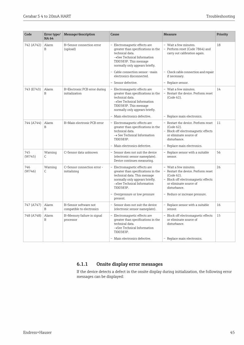
Cerabar S 4 to 20mA HART Troubleshooting
Endress+Hauser 45
6.1.1 Onsite display error messagesIf the device detects a defect in the onsite display during initialization, the following error messages can be displayed:
742 (A742) AlarmB
B>Sensor connection error (upload)
– Electromagnetic effects are greater than specifications in the technical data. See Technical Information TI00383P. This message normally only appears briefly.
– Wait a few minutes.– Perform reset (Code 7864) and
carry out calibration again.
18
– Cable connection sensor –main electronics disconnected.
– Check cable connection and repair if necessary.
– Sensor defective. – Replace sensor.
743 (E743) AlarmB
B>Electronic PCB error during initialization
– Electromagnetic effects are greater than specifications in the technical data. See Technical Information TI00383P. This message normally only appears briefly.
– Wait a few minutes.– Restart the device. Perform reset
(Code 62).
14
– Main electronics defective. – Replace main electronics.
744 (A744) AlarmB
B>Main electronic PCB error – Electromagnetic effects are greater than specifications in the technical data. See Technical Information TI00383P.
– Restart the device. Perform reset (Code 62).
– Block off electromagnetic effects or eliminate source of disturbance.
11
– Main electronics defective. – Replace main electronics.
745 (W745)
WarningC
C>Sensor data unknown – Sensor does not suit the device (electronic sensor nameplate). Device continues measuring.
– Replace sensor with a suitable sensor.
56
746 (W746)
WarningC
C>Sensor connection error - initializing
– Electromagnetic effects are greater than specifications in the technical data. This message normally only appears briefly.See Technical Information TI00383P.
– Wait a few minutes.– Restart the device. Perform reset
(Code 62).– Block off electromagnetic effects
or eliminate source of disturbance.
26
– Overpressure or low pressure present.
– Reduce or increase pressure.
747 (A747) AlarmB
B>Sensor software not compatible to electronics
– Sensor does not suit the device (electronic sensor nameplate).
– Replace sensor with a suitable sensor.
16
748 (A748) AlarmB
B>Memory failure in signal processor
– Electromagnetic effects are greater than specifications in the technical data. See Technical Information TI00383P.
– Block off electromagnetic effects or eliminate source of disturbance.
15
– Main electronics defective. – Replace main electronics.
Code Error type/NA 64
Message/description Cause Measure Priority

Troubleshooting Cerabar S 4 to 20mA HART
46 Endress+Hauser
6.2 Response of outputs to errorsThe device makes a distinction between the error types Alarm, Warning and Error. See also Section 6.1 "Messages" and Page 21 ff, Table 7: OUTPUT and Page 35 ff, Table 15: MESSAGES.
Message Measure
Initialization, VU Electr. Defect A110
Exchange onsite display.
Initialization, VU Electr. Defect A114
Initialization, VU Electr. Defect A281
Initialization, VU Checksum Err. A110
Initialization, VU Checksum Err. A112
Initialization, VU Checksum Err. A171
Output A (Alarm) W (Warning) E (Error: Alarm/Warning)
Current output – Device does not continue measuring.– The current output assumes the value
specified via the OUTPUT FAIL MODE1), ALT. CURR. OUTPUT1 and SET MAX. ALARM.1 See also Operating Instructions BA00412P, Section "Configuring current output for an alarm".
Device continues measuring. For this error, you can enter whether the device should react as in the event of an alarm or as in the event of a warning. See corresponding "Alarm" or "Warning" column.(See also these Operating Instructions, parameter description for SELECT ALARMTYPE.)
Bar graph(onsite display)
The bar graph adopts the value defined by the OUTPUT FAIL MODE 1 parameter.
The bar graph adopts the value which corresponds to the current value.
See this table, "Alarm" or "Warning" column, depending on the option selected.
Onsite display – The measured value and message are displayed alternately
– Measured value display: -symbol is permanently displayed.
– The measured value and message are displayed alternately
– Measured value display: -symbol flashes.
– The measured value and message are displayed alternately
– Measured value display: see corresponding "Alarm" or "Warning" column
Message display– 3-digit number such as A122 and
description
Message display:– 3-digit number such as W613 and
description
Message display:– 3-digit number such as E731 and
description
Remote operation (digital communication)
In the case of an alarm, the ALARM STATUS2) parameter displays a 3-digit number such as 122 for "Sensor not connected".
In the case of a warning, the ALARM STATUS2 parameter displays a 3-digit number such as 613 for "Simulation is active".
In the case of an error, the ALARM STATUS2 parameter displays a 3-digit number such as 731 for "URV user limits exceeded".
1) Menu path: (GROUP SELECTION ) OPERATING MENU OUTPUT
2) Menu path: (GROUP SELECTION ) OPERATING MENU MESSAGES

Cerabar S 4 to 20mA HART Troubleshooting
Endress+Hauser 47
6.3 Confirming messagesDepending on the settings for the ALARM DISPL. TIME (Page 36) and ACK. ALARM MODE (Page 35), the following measures should be taken to clear a message:
If the onsite display displays a message, you can suppress it with the F key. If there are several messages, the onsite display shows the message which has the highest priority (Section 6.1). Once you have suppressed this message using the F key, the message with the next highest priority is displayed. You can use the F key to suppress each message, one after the other.The ALARM STATUS parameter continues to display all the messages present.
Settings1)
1) Menu path for ALARM DISPL. TIME and ACK. ALARM MODE: (GROUP SELECTION ) OPERATING MENU DIAGNOSTICS MESSAGES
Measures
– ALARM DISPL. TIME = 0 s– ACK. ALARM MODE = Off
– Rectify the cause of the message (see also Section 6.1).
– ALARM DISPL. TIME > 0 s– ACK. ALARM MODE = Off
– Rectify the cause of the message (see also Section 6.1).– Wait for the alarm display time to elapse.
– ALARM DISPL. TIME = 0 s– ACK. ALARM MODE = On
– Rectify the cause of the message (see also Section 6.1).– Confirm message using ACK. ALARM parameter.
– ALARM DISPL. TIME > 0 s– ACK. ALARM MODE = On
– Rectify the cause of the message (see also Section 6.1).– Confirm message using ACK. ALARM parameter.– Wait for the alarm display time to elapse. If a message appears and the
alarm display time elapses before the message has been acknowledged, the message will be cleared once it has been acknowledged.

Appendix Cerabar S 4 to 20mA HART
48 Endress+Hauser
7 Appendix
7.1 Operating menu for onsite display and digital communication
• The entire menu is depicted on the following pages.• The menu has a different structure depending on the measuring mode selected. This
means that some function groups are only displayed for one measuring mode.• In addition, there are also parameters that are only displayed if other parameters are
appropriately configured. For example the CUSTOMER UNIT P parameter is only displayed if the "User unit" option was selected for the PRESS. ENG. UNIT parameter. These parameters are indicated with a "*".
• For a description of the parameters, see Section 5 "Description of parameters". The exact dependency of individual parameters on one another is explained here.

Cerabar S 4 to 20mA HART Appendix
Endress+Hauser 49
P01-MIDxxxxx-19-xx-xx-EN-025
*
1)
1)
1)
2)
1)
*
*
2)
1) Display via on-site display only
2) Display via FieldCare andHART Handheld terminal only
Measured value
GROUP SELECTION
QUICK SETUPLANGUAGE
Pressure
SET LRV
POS. INPUT VALUE
SET URV
POS. INPUT VALUE
CALIB. OFFSET
DAMPING VALUE
SETTINGS
OPERATING MENU
POSITION ADJUSTMENT
There are parameters that are only displayed if other parameters are
appropriately configured.
For example the CUSTOMER UNIT P parameter is only displayed
if the "User unit" option was selected for the PRESS. ENG. UNIT parameter.
These parameters are indicated with a "*".
MEASURING MODE
MEASURING MODEMEASURING MODE
LEVEL SELECTION
Level (notfor PMP71 with MID)
provided
Pressure
SET LRV
SET URV
GET LRV
DAMPING VALUE
GET URV
BASIC SETUP
PRESS. ENG. UNIT
CUSTOMER UNIT P
CUST. UNIT FACT. P
MEASURING MODE
Level (notfor PMP71 with MID)
provided
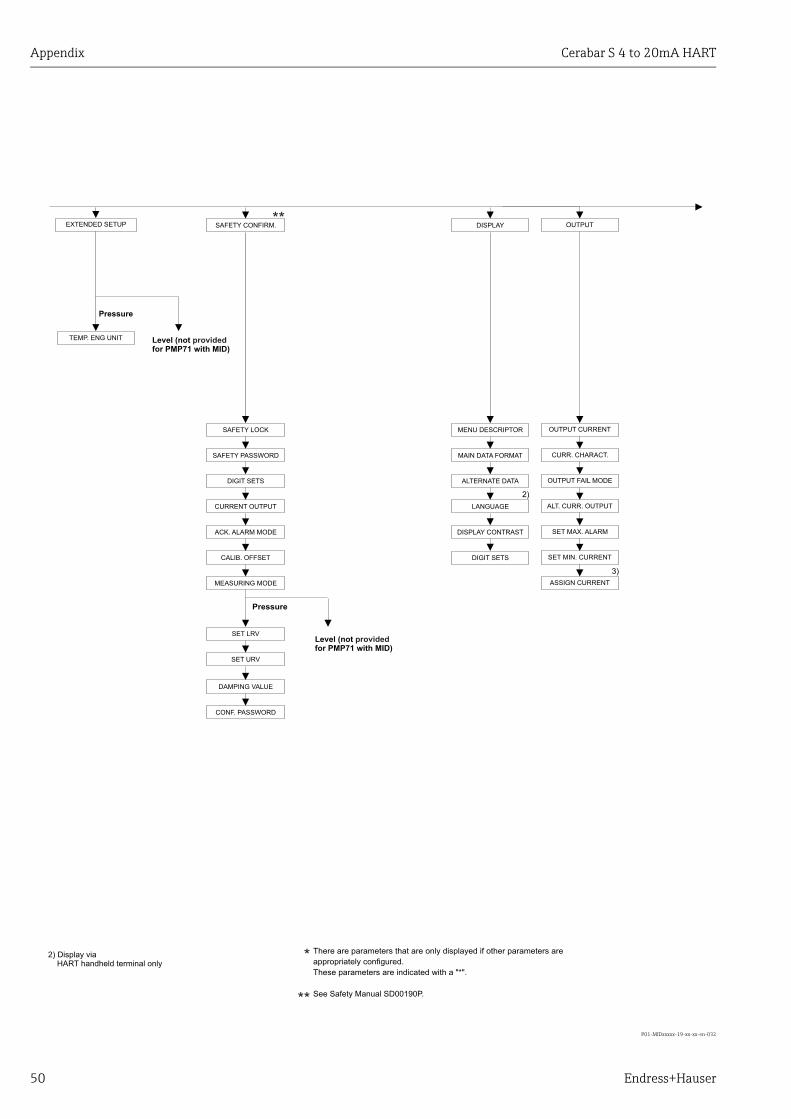
Appendix Cerabar S 4 to 20mA HART
50 Endress+Hauser
P01-MIDxxxxx-19-xx-xx-en-032
**
2)
3)
**
*
CONF. PASSWORD
DAMPING VALUE
SET LRV
SET URV
There are parameters that are only displayed if other parameters are
appropriately configured.
These parameters are indicated with a "*".
See Safety Manual SD00190P.
2) Display viaHART handheld terminal only
Pressure
OUTPUT
SET MAX. ALARM
SET MIN. CURRENT
OUTPUT CURRENT
OUTPUT FAIL MODE
ALT. CURR. OUTPUT
ASSIGN CURRENT
CURR. CHARACT.
DISPLAYSAFETY CONFIRM.
ALTERNATE DATA
DISPLAY CONTRAST
MENU DESCRIPTOR
MAIN DATA FORMAT
SAFETY LOCK
SAFETY PASSWORD
CALIB. OFFSET
MEASURING MODE
CURRENT OUTPUT
DIGIT SETS
ACK. ALARM MODE
LANGUAGE
DIGIT SETS
Level (notfor PMP71 with MID)
provided
EXTENDED SETUP
Pressure
TEMP. ENG UNIT Level (notfor PMP71 with MID)
provided

Cerabar S 4 to 20mA HART Appendix
Endress+Hauser 51
P01-MIDxxxxx-19-xx-xx-en-033
*
2)
2)
2)
2)
2)
2)
2)
2)
2)
2)
2)
2)
2)
2)
2)
2)
2)
2)
2)
2)
2)
2)
MEASURED VALUE
PROCESS VALUE
PROCESS INFO
Pressure
PEAK HOLD INDICATOR
COUNTER:T > Tmax
MAX. MEAS. TEMP.
COUNTER:T< Tmin
MIN. MEAS. TEMP.
COUNTER:P > Pmax
MAX. MEAS. PRESS.
COUNTER:P < Pmin
MIN. MEAS. PRESS.
PCB COUNT:T > Tmax
PCB MAX. TEMP.
PCB COUNT: T< Tmin
PCB MIN. TEMP.
RESET PEAKHOLD
SENSOR TEMP.
MEAS. VAL. TREND
PRESSURE
CORRECTED PRESS.
SENSOR PRESSURE
There are parameters that are only displayed if other parameters are
appropriately configured.
These parameters are indicated with a "*".
TRANSMITTER INFO
HART DATA
MANUFACTOR ID
HART MESSAGE
BUS ADDRESS
DEVICE REVISION
PREAMBLE NUMBER
HART DATE
DEVICE TYPE
TRANSMITTER DATA
DEVICE SERIAL No
CUST. TAG NUMBER
ELECTR. SERIAL No
DEVICE DESIGN.
HARDWARE REV.
ADDITIONAL INFO.
SOFTWARE VERSION
CONFIG RECORDER
PCB TEMPERATURE
ALLOWED MIN. TEMP
ALLOWED MAX. TEMP
DIP STATUS
LONG TAG NUMBER
PROCESS CONNECTION
SEAL TYPE
Pmax PROC. CONN.
MAT. PROC. CONN. +
MAT. PROC. CONN. –
PROC. CONN. TYPE
SENSOR DATA
SENSOR MEAS. TYPE
Pmin SENS. DAMAGE
SENSOR SER. NO.
PRESS. SENS HILIM
MINIMUM SPAN
Pmax SENS. DAMAGE
MAT. MEMBRANE
PRESS. SENS LOLIM
FILLING FLUID
Tmin SENSOR
Tmax SENSOR
SENSOR H/WARE REV.
DIAPHRAGM MAT. +
DIAPHRAGM MAT. –
NR OF REMOTE SEAL
FILL FLUID
MOUNTING THREAD
REMOTE SEAL +
REMOTE SEAL –
NUTS MATERIAL
DRAIN VENT MAT.
DRAIN VENT POS.
THREAD
BOLTS MATERIAL
4TH VALUE IS
4 TH VALUE
SECONDARY VALUE
THIRD VALUE IS
THIRD VALUE
PRIMARY VALUE IS
PRIMARY VALUE
SECONDARY VAL. IS
2) Display via FieldCare andHART handheld terminal only
BURST MODE
BURST OPTION
Level (notfor PMP71 with MID)
provided

Appendix Cerabar S 4 to 20mA HART
52 Endress+Hauser
P01-PMx7xxxx-19-xx-xx-xx-044
*
*
I
*
I
*HistoROM CONTROL
SIM. CURRENTSIM. LEVELSIM. PRESSURE SIM. TANK CONT. SIM. ERROR NO.
Display via HART handheldterminal only
Pmin ALARM WINDOW
Pmax ALARM WINDOW
Tmin ALARM WINDOW
Tmax ALARM WINDOW
RESET ALL ALARMS
SELECT ALARMTYPE
ALARM DELAY
ALARM DISPL. TIME
ALARM STATUS
LAST DIAG. CODE
ACK. ALARM MODE
ACK. ALARM
ERROR NO.
SIMULATION MODE
OPERATING HOURS
INSERT PIN NO
HistoROM AVAIL.
DOWNLOAD SELECT.
OPERATION DIAGNOSTICS
SIMULATION MESSAGES USER LIMITS
Alarm Warningnone LevelPressure Tank content Current
ENTER RESET CODE
There are parameters that are only displayed if other parameters are
appropriately configured.
These parameters are indicated with a "*".
SYSTEM 2
CURR. TRIM 4mA
CURR. TRIM 20mA
OFFSET 4mA TRIM
OFFSET 20mA TRIM
SERVICE

Cerabar S 4 to 20mA HART Appendix
Endress+Hauser 53

Appendix Cerabar S 4 to 20mA HART
54 Endress+Hauser

Cerabar S 4 to 20mA HART
Endress+Hauser 55
Index
Numerics4TH VALUE . . . . . . . . . . . . . . . . . . . . . . . . . . . . . . . . . . . . 264TH VALUE IS . . . . . . . . . . . . . . . . . . . . . . . . . . . . . . . . . . 26
AACK. ALARM (500). . . . . . . . . . . . . . . . . . . . . . . . . . . . . . 35ACK. ALARM MODE (401) . . . . . . . . . . . . . . . . . . . . . . . 35ACK. ALARM MODE (844), "Safety confirm." group . . . . . 6ADDITIONAL INFO. (272) . . . . . . . . . . . . . . . . . . . . . . . . 26ALARM DELAY (336) . . . . . . . . . . . . . . . . . . . . . . . . . . . . 36ALARM DISPL. TIME (480) . . . . . . . . . . . . . . . . . . . . . . . 36ALARM STATUS (046) . . . . . . . . . . . . . . . . . . . . . . . . . . . 35ALLOWED MAX. TEMP (359). . . . . . . . . . . . . . . . . . . . . 26ALLOWED MIN. TEMP (358) . . . . . . . . . . . . . . . . . . . . . 26ALT.CURR.OUTPUT (597) . . . . . . . . . . . . . . . . . . . . . . . . 22ALTERNATE DATA (423) . . . . . . . . . . . . . . . . . . . . . . . . 19
BBOLTS MATERIAL. . . . . . . . . . . . . . . . . . . . . . . . . . . . . . . 28BURST MODE . . . . . . . . . . . . . . . . . . . . . . . . . . . . . . . . . . . 25BURST OPTION . . . . . . . . . . . . . . . . . . . . . . . . . . . . . . . . . 25BUS ADDRESS (345) . . . . . . . . . . . . . . . . . . . . . . . . . . . . . 24
CCALIB. OFFSET (319) . . . . . . . . . . . . . . . . . . . . . . . . . . . . 14CALIB. OFFSET (847), "Safety confirm." group. . . . . . . . . . 6CONF. PASSWORD (856) . . . . . . . . . . . . . . . . . . . . . . . . . . . 6CONFIG RECORDER (352) . . . . . . . . . . . . . . . . . . . . . . . . 26CORRECTED PRESS. (434), "Pressure" measuring mode 31CURR. CHARACT. (694), (695), (696), (764) . . . . . . . . 22CURR. TRIM 20mA (042). . . . . . . . . . . . . . . . . . . . . . . . . 38CURR. TRIM 4mA (045) . . . . . . . . . . . . . . . . . . . . . . . . . . 38CURRENT OUTPUT (875). . . . . . . . . . . . . . . . . . . . . . . . . . . 6CUST. TAG NUMBER (055) . . . . . . . . . . . . . . . . . . . . . . . 26CUST.UNIT FACT.P (317). . . . . . . . . . . . . . . . . . . . . . . . . 16CUSTOMER UNIT P (075) . . . . . . . . . . . . . . . . . . . . . . . . 16
DDAMPING VALUE (247) . . . . . . . . . . . . . . . . . . . . . . 13, 17DAMPING VALUE (855), "Safety confirm." group . . . . . . . 6DEVICE DESIGN. (350) . . . . . . . . . . . . . . . . . . . . . . . . . . . 26DEVICE REVISION (699). . . . . . . . . . . . . . . . . . . . . . . . . . 24DEVICE SERIAL No (354) . . . . . . . . . . . . . . . . . . . . . . . . . 26DEVICE TYPE (802), Cerabar S . . . . . . . . . . . . . . . . . . . . 24DIAPHRAG. MAT. - . . . . . . . . . . . . . . . . . . . . . . . . . . . . . . 28DIAPHRAG. MAT. + . . . . . . . . . . . . . . . . . . . . . . . . . . . . . 28DIGITS SET (841), "Safety confirm." group . . . . . . . . . . . . . 6DIGITS SET, "Display" group. . . . . . . . . . . . . . . . . . . . . . . . 20DIP STATUS (363). . . . . . . . . . . . . . . . . . . . . . . . . . . . . . . 27DISPLAY CONTRAST (339) . . . . . . . . . . . . . . . . . . . . . . . 20DOWNLOAD SELECT (014) . . . . . . . . . . . . . . . . . . . . . . . 33DRAIN VENT MAT. . . . . . . . . . . . . . . . . . . . . . . . . . . . . . . 28DRAIN VENT POS. . . . . . . . . . . . . . . . . . . . . . . . . . . . . . . . 28
EELECTR. SERIAL No (386) . . . . . . . . . . . . . . . . . . . . . . . . 26ENTER RESET CODE (047). . . . . . . . . . . . . . . . . . . . . . . . 32
ERROR No. . . . . . . . . . . . . . . . . . . . . . . . . . . . . . . . . . . . . . . 35
FFILL FLUID . . . . . . . . . . . . . . . . . . . . . . . . . . . . . . . . . . . . . . 29FILLING FLUID (366) . . . . . . . . . . . . . . . . . . . . . . . . . . . . . 29
GGET LRV (309), "Pressure" measuring mode . . . . . . . . . . 17GET URV (310), "Pressure" measuring mode . . . . . . . . . . 17
HHARDWARE REV. (266) . . . . . . . . . . . . . . . . . . . . . . . . . . 26HART DATE (481) . . . . . . . . . . . . . . . . . . . . . . . . . . . . . . . 25HART MESSAGE (271). . . . . . . . . . . . . . . . . . . . . . . . . . . . 25HistoROM AVAIL. (831) . . . . . . . . . . . . . . . . . . . . . . . . . . 33HistoROM CONTROL (832) . . . . . . . . . . . . . . . . . . . . . . . . 33
IINSERT PIN NO (048). . . . . . . . . . . . . . . . . . . . . . . . . . . . . 33
LLANGUAGE (079). . . . . . . . . . . . . . . . . . . . . . . . . . . . . . . . 11LANGUAGE, display group. . . . . . . . . . . . . . . . . . . . . . . . . 20LAST DIAG. CODE (564) . . . . . . . . . . . . . . . . . . . . . . . . . . 35LONG TAG NUMBER (305) . . . . . . . . . . . . . . . . . . . . . . . . 26
MMAIN DATA FORMAT (688) . . . . . . . . . . . . . . . . . . . . . . 19MANUFACTOR ID (432) . . . . . . . . . . . . . . . . . . . . . . . . . . 25MAT. MEMBRANE (365) . . . . . . . . . . . . . . . . . . . . . . . . . 29MAT. PROC. CONN. + (360) . . . . . . . . . . . . . . . . . . . . . . . 27MEAS. VAL. TREND (378). . . . . . . . . . . . . . . . . . . . . . . . . 31MEASURED VALUE, "Pressure" measuring mode . . . . . . 30MEASURING MODE (845), "Safety confirm." group . . . . . 6MEASURING MODE, digital communication. . . . . . 12, 15MENU DESCRIPTOR (419). . . . . . . . . . . . . . . . . . . . . . . . . 19MINIMUM SPAN (591) . . . . . . . . . . . . . . . . . . . . . . . . . . . 29MOUNTING THREAD . . . . . . . . . . . . . . . . . . . . . . . . . . . . . 28
NNR OF REMOTE SE . . . . . . . . . . . . . . . . . . . . . . . . . . . . . . . 28NUTS MATERIAL . . . . . . . . . . . . . . . . . . . . . . . . . . . . . . . . 28
OOFFSET 20mA TRIM (044) . . . . . . . . . . . . . . . . . . . . . . . . 38OFFSET 4mA TRIM (043) . . . . . . . . . . . . . . . . . . . . . . . . . 38OPERATING HOURS (409). . . . . . . . . . . . . . . . . . . . . . . . . 32OUTPUT CURRENT (254) . . . . . . . . . . . . . . . . . . . . . . . . . 21OUTPUT FAIL MODE (388) . . . . . . . . . . . . . . . . . . . . . . . . 22
PPASSWORD (836). . . . . . . . . . . . . . . . . . . . . . . . . . . . . . . . . 6PCB TEMPERATURE (357) . . . . . . . . . . . . . . . . . . . . . . . . 26Pmax ALARM WINDOW (333). . . . . . . . . . . . . . . . . . . . . 36Pmax PROC. CONN. (570) . . . . . . . . . . . . . . . . . . . . . . . . . 27Pmin ALARM WINDOW (332) . . . . . . . . . . . . . . . . . . . . . 36POS. INPUT VALUE (563) . . . . . . . . . . . . . . . . . . . . . 13–14

Cerabar S 4 to 20mA HART
56 Endress+Hauser
PREAMBLE NUMBER (036) . . . . . . . . . . . . . . . . . . . . . . . 25PRESS. ENG. UNIT (060) . . . . . . . . . . . . . . . . . . . . . . . . . . 16PRESS. SENS HILIM (485) . . . . . . . . . . . . . . . . . . . . . . . . . 29PRESS. SENS LOLIM (484) . . . . . . . . . . . . . . . . . . . . . . . . 29PRESSURE, "Pressure" measuring mode . . . . . . . . . . . . . . 31PRIMARY VALUE . . . . . . . . . . . . . . . . . . . . . . . . . . . . . . . . 25PRIMARY VALUE IS . . . . . . . . . . . . . . . . . . . . . . . . . . . . . . 25PROC. CONN. TYPE (482) . . . . . . . . . . . . . . . . . . . . . . . . . 27
QQuick Setup "Pressure" menu . . . . . . . . . . . . . . . . . . . . . . . 12
RREMOTE SEAL - . . . . . . . . . . . . . . . . . . . . . . . . . . . . . . . . . 28REMOTE SEAL + . . . . . . . . . . . . . . . . . . . . . . . . . . . . . . . . . 28RESET ALL ALARMS (603). . . . . . . . . . . . . . . . . . . . . . . . 35
SSAFETY LOCKSTATE (836). . . . . . . . . . . . . . . . . . . . . . . . . 6SEAL TYPE (362) . . . . . . . . . . . . . . . . . . . . . . . . . . . . . . . . 28SECONDARY VAL. IS . . . . . . . . . . . . . . . . . . . . . . . . . . . . . 25SECONDARY VALUE . . . . . . . . . . . . . . . . . . . . . . . . . . . . . 25SELECT ALARMTYPE (595), (600) . . . . . . . . . . . . . . . . . 36SENS H/WARE REV (487) . . . . . . . . . . . . . . . . . . . . . . . . 29SENSOR MEAS.TYPE (581). . . . . . . . . . . . . . . . . . . . . . . . 29SENSOR PRESSURE (584), "Pressure" measuring mode . 31SENSOR SER. No. (250) . . . . . . . . . . . . . . . . . . . . . . . . . . . 29SENSOR TEMP. (367) . . . . . . . . . . . . . . . . . . . . . . . . . . . . 31SET LRV (245), "Pressure" measuring mode . . . . . . 13, 16SET LRV (852), "Safety confirm." group . . . . . . . . . . . . . . . 6SET MAX. ALARM (342). . . . . . . . . . . . . . . . . . . . . . . . . . 23SET MIN. CURRENT (343). . . . . . . . . . . . . . . . . . . . . . . . . 23SET URV (246), "Pressure" measuring mode . . . . . . 13, 16SET URV (853), "Safety confirm." group. . . . . . . . . . . . . . . 6SIM. CURRENT (270) . . . . . . . . . . . . . . . . . . . . . . . . . . . . . 34SIM. ERROR NO. (476). . . . . . . . . . . . . . . . . . . . . . . . . . . . 34SIM. PRESSURE (414) . . . . . . . . . . . . . . . . . . . . . . . . . . . . 34SIMULATION MODE (413) . . . . . . . . . . . . . . . . . . . . . . . . 34SOFTWARE VERSION (264) . . . . . . . . . . . . . . . . . . . . . . . 26
TTEMP. ENG. UNIT (318), "Pressure" measuring mode . . 18THIRD VALUE . . . . . . . . . . . . . . . . . . . . . . . . . . . . . . . . . . . 26THIRD VALUE IS . . . . . . . . . . . . . . . . . . . . . . . . . . . . . . . . . 26THREAD PROCESS . . . . . . . . . . . . . . . . . . . . . . . . . . . . . . . 28Tmax ALARM WINDOW (335) . . . . . . . . . . . . . . . . . . . . 37Tmax SENSOR (369) . . . . . . . . . . . . . . . . . . . . . . . . . . . . . 29Tmin ALARM WINDOW (334). . . . . . . . . . . . . . . . . . . . . 37Tmin SENSOR (368). . . . . . . . . . . . . . . . . . . . . . . . . . . . . . 29

Cerabar S 4 to 20mA HART
Endress+Hauser 57

58

59

www.addresses.endress.com
71335863