Chiral arylpyrrolidinols: preparation and biological profile
Upload
kharkov-uaCategory
view
1download
0
1PfTedafi
orrswtomapp
tivaEecstsisrtcec
2704 J. Opt. Soc. Am. A/Vol. 25, No. 11 /November 2008 V. R. Tuz and V. B. Kazanskiy
Depolarization properties of a periodic sequenceof chiral and material layers
Vladimir R. Tuz* and Vadim B. Kazanskiy
Department of Theoretical Radio Physics, Kharkov National University, Svobody Square 4, Kharkov, Ukraine*Corresponding author: [email protected]
Received April 23, 2008; revised August 14, 2008; accepted September 1, 2008;posted September 4, 2008 (Doc. ID 95333); published October 15, 2008
We consider the electromagnetic field due to the reflection and transmission of a plane wave by a boundedperiodic structure containing chiral layers. The problem is solved using the 2�2-block-representation transfer-matrix formulation. The frequency and angular dependences of the reflection and transmission coefficients aregiven. The boundaries of the passbands and stopbands are determined from the basic-element transfer-matrixeigenvalue analysis. © 2008 Optical Society of America
OCIS codes: 260.5430, 290.5855, 230.4170, 160.1585, 230.1480.
nscsaAsmttcsia
otstilari
2Abt(c�zt
tu
m
. INTRODUCTIONeriodic structures are gaining widespread use as
requency-selective filters, radomes, and polarizers [1–6].hey are critical components in vertical-cavity surface-mitting lasers and other types of narrow-linewidth laseriodes such as distributed feedback lasers [7,8]. They arelso used to form the cavity resonator (or optical cavity) inber lasers and free electron lasers.In the past two decades, much research has been done
n periodic structures that include layers made of mate-ial with spatial dispersion [bi-anisotropic, reciprocal (chi-al), and nonreciprocal bi-isotropic media] [9–14]. Suchtructures realize the polarization transformation of theaves in additional to their spatial and frequency selec-
ion. In the present work the electromagnetic propertiesf the bounded periodic sequence of alternating isotropicagnetodielectric and chiral layers are investigated. The
im of this work is improvement in performance and ex-ansion of the functionality of optical systems through ex-loitation of media chirality.Transfer matrix methods are widely used to analyze
he propagation of light through a layered medium. Forsotropic layered media the solution is usually describedia 2�2 matrices [1–5]. The e (electric-field vector E par-llel to the plane of incidence) and h (electric-field vectorperpendicular to the plane of incidence) modes of plane
lectromagnetic waves are independent of each other (un-oupled modes). Thus the wave propagation can be de-cribed separately for each mode. For each component ofhe layered media such as ambient, slab, …, slab, sub-trate, there exists a matrix that contains the ratio of thencident and the emerging parts of each mode with re-pect to an appropriate coordinate system. All multipleeflections between the slab interfaces that may occur inhe case of transparent layers are retained in a self-onsistent way. From the product of all matrices, one canasily compute the reflection and transmission coeffi-ients for the e and h modes.
When a system includes chiral layers, the four mag-
1084-7529/08/112704-6/$15.00 © 2
etic and electric parts of the plane wave are no longerpatially independent of each other, and so-called modeoupling appears. In this case the solution is usually de-cribed via 2�2 matrices separately for the right-handnd the left-hand circularly polarized plane wave [12,13].nother method is proposed in [15], where Berremanhows a general way to calculate the reflection and trans-ission coefficients of an anisotropic slab from a wave
ransfer matrix of rank 4. In a manner similar to that forhe isotropic case, these matrices connect the in-planeomponents of all modes of the plane waves at two oppo-ite interfaces. This method of 4�4 differential matricess applied in [14] to analyze a structure with bi-nisotropic layers.In the present work the reflected and transmitted fields
f a bounded periodic sequence with chiral layers are de-ermined using the orthogonal reference frame, and theolution is described via the 2�2-block-representationransfer-matrix formulation [16,17]. This method general-zes the 2�2-matrix approach applied to right-hand andeft-hand circular wave polarization and the 4�4-matrixpproach of Berreman [14] and allows the investigation ofeflection and transmission in terms of linear-wave polar-zation.
. PROBLEM FORMULATIONperiodic sequence (in the z-axis direction) of N identical
asic elements (periods) is investigated (Fig. 1). Each ofhe periods includes a homogeneous magnetodielectricwith permittivities �1, �1) and chiral (with �2, �2 andhirality parameter �) layers with thicknesses d1 and d2L=d1+d2�, respectively. The outer half-spaces z�0 and�NL are homogeneous and isotropic and have permit-ivities �0, �0 and �3, �3, respectively.
Note that if �=0 (i.e., both layers are conventional ma-erials), then the structure in Fig. 1 is known as a distrib-ted Bragg reflector (DBR) [2–4].As the excitation fields, the plane (in the XOZ plane)onochromatic waves �exp�−i�t�� with perpendicular
008 Optical Society of America

(sa
xta
w=
�pc
wi
Htt
b
wY=cTp
plsfWn+o
H==
V. R. Tuz and V. B. Kazanskiy Vol. 25, No. 11 /November 2008 /J. Opt. Soc. Am. A 2705
Ee �x0, Hxe =0) or parallel (Hh �x0, Ex
h=0) polarization areelected (E and H waves). They are obliquely incident atn angle �0 to the z axis from the region z�0.In the chiral layers that are homogeneous along the
-direction, the electromagnetic field is characterized byhe displacements D=�2E− i�H and B=�2H+ i�E [9,10]nd are governed by the coupled differential equations
�Ex + k02�n2
2 + �2�Ex − 2ik02��2Hx = 0,
�Hx + k02�n2
2 + �2�Hx + 2ik02�2Ex = 0, �1�
here n2=��2�2 is the medium refractive index and �
�2 /�y2+�2 /�z2 is the two-dimensional Laplacian.The waves of the perpendicular �Ee �x0� and parallel
Hh �x0� linear polarizations can be presented as the su-erposition of the waves of the right �Qs
+� and left �Qs−� cir-
ular polarizations [11]:
Exe = Qe
+ + Qe−, Hx
e = i�2−1�Qe
+ − Qe−�,
Exh = − i�2�Qh
+ − Qh−�, Hx
h = Qh+ + Qh
−, �2�
here �2=��2 /�2. Such a substitution transforms Eq. (1)nto two independent Helmholtz equations:
�Qs+ + ��+�2Qs
+ = 0, �Qs− + ��−�2Qs
− = 0. �3�
ere s=e ,h, �±=k0�n±�� is the propagation constant ofhe right and left circularly polarized plane wave, respec-ively, in the unbounded chiral medium.
The general solutions for the RCP and LCP waves in aounded chiral layer can be written as
Qe± =
1
2�Ye±�Ae± exp�i��y
±y + �z±z�� + Be± exp�i��y
±y − �z±z���,
Qh± =
�Yh±
2�Ah± exp�i��y
±y + �z±z�� + Bh± exp�i��y
±y − �z±z���,
�4�
here As±, Bs± are the wave amplitudes; Y2e±=�2
−1 cos �±,
2h±= ��2 cos �±�−1 are the wave admittances; �y
±
�± sin �±, �z±=�± cos �±, �± is the refraction angle in the
hiral medium; sin �±=sin �0n0 / �n2±��; and n0=��0�0.he substitution of Eq. (4) into Eq. (2) gives the field com-onents of the e and h polarizations.
Fig. 1. Bounded periodic seq
Due to the reflection and transmission of the givenolarization-plane electromagnetic wave �s� by the chiralayers, cross-polarization components �s� � appear in theecondary field. Denote their amplitudes as As� and Bs�or the transmitted and the reflected wave, respectively.
ith the notation zm=mL, zm1=mL+d1, the field compo-ents in the mth period, zm�z�zm1 and zm1�z� �m1�L, are written as follows (the factor exp�−i��t−kyy�� ismitted):
Ex1e
Ey1h = ±1/�Y1
e
i/�Y1h�Am
e
Amheikz1�z−zm� ± Bm
e
Bmhe−ikz1�z−zm�� ,
Hy1e
Hx1h = �Y1
e
i�Y1h�Am
e
Amheikz1�z−zm� Bm
e
Bmhe−ikz1�z−zm�� ,
�5�
Ex2
Ey2 = ±1/2�Y2
e+
i/2�Y2h+�Am
+ ei�z+�z−zm1� ± Bm
+ e−i�z+�z−zm1��
+1/2�Y2e−
i/2�Y2h−�Am
− ei�z−�z−zm1� ± Bm
− e−i�z−�z−zm1��,
Hy2
Hx2 = �Y2
e+/2
i�Y2h+/2
��Am+ ei�z
+�z−zm1� Bm+ e−i�z
+�z−zm1�� ± �Y2e−/2
i�Y2h−/2
��Am− ei�z
−�z−zm1� Bm− e−i�z
−�z−zm1��, �6�
The field components at the structure output are
Ex3e
Ey3h = ±�1/�Y3
e�AN+1e
�i/�Y3h�AN+1
h eikz3�z−NL�, Hy3e
Hx3h
= �Y3eAN+1
e
i�Y3hAN+1
h eikz3�z−NL�. �7�
ere kzj=kj cos �j, kyj=kj sin �j, kj=k0nj, nj=��j�j, Yje
�j−1 cos �j, Yj
h= ��j cos �j�−1, �j=��j /�j, sin �jsin � n /n , and j=0,1,3.
of material and chiral layers.
uence0 0 j

3MTtca
wit
c
ac
wb
wr
tt
2706 J. Opt. Soc. Am. A/Vol. 25, No. 11 /November 2008 V. R. Tuz and V. B. Kazanskiy
. METHOD OF SOLUTION. TRANSFERATRIX
he equations coupling the field amplitudes at the struc-ure input �A0
s ,B0s ,B0
s�� and output �AN+1s ,AN+1
s� � for the in-ident fields of the E type �A0
h=0� and the H type �A0e =0�
re obtained as
A0
s
B0s
0
B0s�� = T01TN−1T�
AN+1s
0
AN+1s�
0�,
Ams
Bms
Ams�
Bms�� = T1
Am+
Bm+
Am−
Bm−� ,
Am
+
Bm+
Am−
Bm−� = T2
Am+1s
Bm+1s
Am+1s�
Bm+1s�
�, Am
s
Bms
Ams�
Bms�� = T1T2
Am+1s
Bm+1s
Am+1s�
Bm+1s�
� , �8�
here T01, T=T1T2, T� are the transfer matrices of thelluminated boundary, the repeated heterogeneity, andhe last element, which is loaded with the waveguide
hannel having the admittance Y3s , respectively (Fig. 1).
In [16], it has been shown that T01TN−1T� =T01TNT13,nd in the block representation �2�2� the transfer matri-es are
Tp� = ��Tp�s � 0
0 �Tp�s���, T1 = � �T1+
ss � �T1−ss �
�T1+ss�� �T1−
ss��� ,
T2 = ��T2+ss � �T2+
ss��
�T2−ss � �T2−
ss��� , �9�
here Tp� corresponds to the matrices T01 and T13. Thelocks of the quasi-diagonal matrices are
Tp�s =
1
2�YpsY�
s� Yps + Y�
s ±�Yps − Y�
s�
±�Yps − Y�
s� Yps + Y�
s � , �10�
here the upper sign relates to s=h and the lower signelates to s=e in terms of the wave types.
The elements of the transfer matrices T1 and T2 are de-ermined by solving the boundary-value problem relatedo the field components (5) and (6). They are
2±,
2±,
T1±ee =
1
4�Y1eY2
e±�Y1e + Y2
e± Y1e − Y2
e±
Y1e − Y2
e± Y1e + Y2
e±�E1, T1±eh = ±
1
4�Y1hY2
h±�Y2h± + Y1
h Y2h± − Y1
h
Y2h± − Y1
h Y2h± + Y1
h�E1,
T1±hh =
1
4�Y1hY2
h±�Y2h± + Y1
h Y2h± − Y1
h
Y2h± − Y1
h Y2h± + Y1
h�E1, T1±he =
1
4�Y1eY2
e±�Y1e + Y2
e± Y1e − Y2
e±
Y1e − Y2
e± Y1e + Y2
e±�E1, �11�
T2±ee =
1
4Y2e �Y1
eY2e±
� ��Y2e + Y1
e��Y2e + Y2
e±� − �Y2e − Y1
e��Y2e − Y2
e±� �Y2e − Y1
e��Y2e + Y2
e±� − �Y2e + Y1
e��Y2e − Y2
e±�
�Y2e − Y1
e��Y2e + Y2
e±� − �Y2e + Y1
e��Y2e − Y2
e±� �Y2e + Y1
e��Y2e + Y2
e±� − �Y2e − Y1
e��Y2e − Y2
e±��E2±,
�12�
T2±eh =
1
4Y2h �Y1
hY2h±
� ��Y2h + Y1
h��Y2h + Y2
h±� − �Y2h − Y1
h��Y2h − Y2
h±� �Y2h + Y1
h��Y2h − Y2
h±� − �Y2h − Y1
h��Y2h + Y2
h±�
�Y2h + Y1
h��Y2h − Y2
h±� − �Y2h − Y1
h��Y2h + Y2
h±� �Y2h + Y1
h��Y2h + Y2
h±� − �Y2h − Y1
h��Y2h − Y2
h±��E
�13�
T2±hh =
1
4Y2h �Y1
hY2h±
� ��Y2h + Y1
h��Y2h + Y2
h±� − �Y2h − Y1
h��Y2h − Y2
h±� �Y2h + Y1
h��Y2h − Y2
h±� − �Y2h − Y1
h��Y2h + Y2
h±�
�Y2h + Y1
h��Y2h − Y2
h±� − �Y2h − Y1
h��Y2h + Y2
h±� �Y2h + Y1
h��Y2h + Y2
h±� − �Y2h − Y1
h��Y2h − Y2
h±��E
�14�
w=
flmRc
4TTgtqvp
ad
wmrt=
Fl
V. R. Tuz and V. B. Kazanskiy Vol. 25, No. 11 /November 2008 /J. Opt. Soc. Am. A 2707
T2±he =
1
4Y2e �Y1
eY2e±
� ��Y2e + Y1
e��Y2e + Y2
e±� − �Y2e − Y1
e��Y2e − Y2
e±� �Y2e − Y1
e��Y2e + Y2
e±� − �Y2e + Y1
e��Y2e − Y2
e±�
�Y2e − Y1
e��Y2e + Y2
e±� − �Y2e + Y1
e��Y2e − Y2
e±� �Y2e + Y1
e��Y2e + Y2
e±� − �Y2e − Y1
e��Y2e − Y2
e±��E2±,
�15�
=[
Pesntbm
wEetcp
tf
here E1=Diag�exp�−ikz1d1� exp�−ikz1d1��, E2±
Diag�exp�−i�z±d2� exp�i�z
±d2��.The reflection and transmission coefficients of the re-
ected �z�0� and transmitted �z�NL� fields are deter-ined by the expressions Rss=B0
s /A0s , �ss=AN+1
s /A0s and
ss�=B0s� /A0
s , �ss�=AN+1s� /A0
s for the co-polarization and theross-polarization wave, respectively.
. EIGENWAVES AND REFLECTION ANDRANSMISSION FIELDShe level of the wave reflection and transmission in aiven frequency band depends on the eigenwave propaga-ion conditions in the corresponding infinite layer se-uence [2]. For their analysis a numerical–analytical in-estigation of the parametric dependences of the one-eriod transfer-matrix eigenvalues is required.The eigenvalues of the transfer matrix, �j �j=1,2,3,4�,
re the roots of the characteristic equation of the unimo-ular matrix T:
Det�T − �I� � �4 − a1�3 + a2�2 − a3� + 1 = 0, �16�
here ap �p=1,2,3� are the pth-order main minors of theatrix �tjk�. According to the Viete theorem about the
oots of polynomials, we have �1�2�3�4=1. This meanshat either the roots are mutually inverse values ��1�2�3�4=1� or one of them can be found via the others ��4
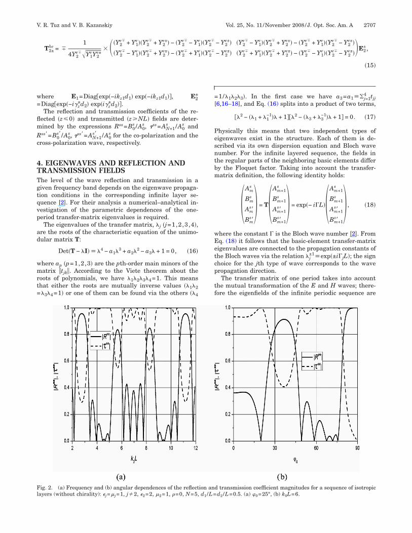
ig. 2. (a) Frequency and (b) angular dependences of the reflectayers (without chirality): =� =1, j�2, =2, � =1, �=0, N=5,
j j 2 2 11/�1�2�3�. In the first case we have a3=a1��j=14 tjj
6,16–18], and Eq. (16) splits into a product of two terms,
��2 − ��1 + �1−1�� + 1���2 − ��3 + �3
−1�� + 1� = 0. �17�
hysically this means that two independent types ofigenwaves exist in the structure. Each of them is de-cribed via its own dispersion equation and Bloch waveumber. For the infinite layered sequence, the fields inhe regular parts of the neighboring basic elements differy the Floquet factor. Taking into account the transfer-atrix definition, the following identity holds:
Am
s
Bms
Ams�
Bms�� = T
Am+1s
Bm+1s
Am+1s�
Bm+1s�
� = exp�− i�L� Am+1
s
Bm+1s
Am+1s�
Bm+1s�
� , �18�
here the constant � is the Bloch wave number [2]. Fromq. (18) it follows that the basic-element transfer-matrixigenvalues are connected to the propagation constants ofhe Bloch waves via the relation �j
±1�exp�±i�jL�; the signhoice for the jth type of wave corresponds to the waveropagation direction.The transfer matrix of one period takes into account
he mutual transformation of the E and H waves; there-ore the eigenfields of the infinite periodic sequence are
d transmission coefficient magnitudes for a sequence of isotropicd /L=0.5. (a) � =25°, (b) k L=6.
ion and /L=
2 0 0
daic
Wpv
ew
Ig
Fl (a) �0
Fs
2708 J. Opt. Soc. Am. A/Vol. 25, No. 11 /November 2008 V. R. Tuz and V. B. Kazanskiy
escribed via all components of the vectors of the electricnd magnetic fields. This field is the superposition of twondependent Bloch waves, which differ by the propagationonstant.
For arbitrary systems, �j=�j� + i�j
� is a complex value.hen the optical loss is vanishingly small, it takes a
urely real �Im �j=0� or a purely imaginary �Re �j=0�alue. In the first case, the frequency range and the basic-
ig. 3. (a) Frequency and (b) angular dependences of the reflecayers: j=�j=1, j�2, 2=2, �2=1, �=0.1, N=5, d1 /L=d2 /L=0.5.
ig. 4. (a) Frequency and (b) angular dependences of the refletructure is placed on a perfectly reflecting surface: =� =1, j�
j j 2lement parameters provide the propagation of the jthave, and with the condition �j+�j
−1�2 it follows that
�j±1 = cos �jL ± i sin �jL. �19�
n the second case �Re �j=0�, the wave does not propa-ate, and �j
±1�exp�±�j�L�.
nd transmission coefficient magnitudes for a sequence of chiral=25°, (b) k0L=6.
oefficient magnitudes for a sequence of chiral layers when the=2, � =1, N=5, d /L=d /L=0.5. (a) � =25°, (b) k L=6, �=0.1.
tion a
ction c2,3,
2 1 2 0 0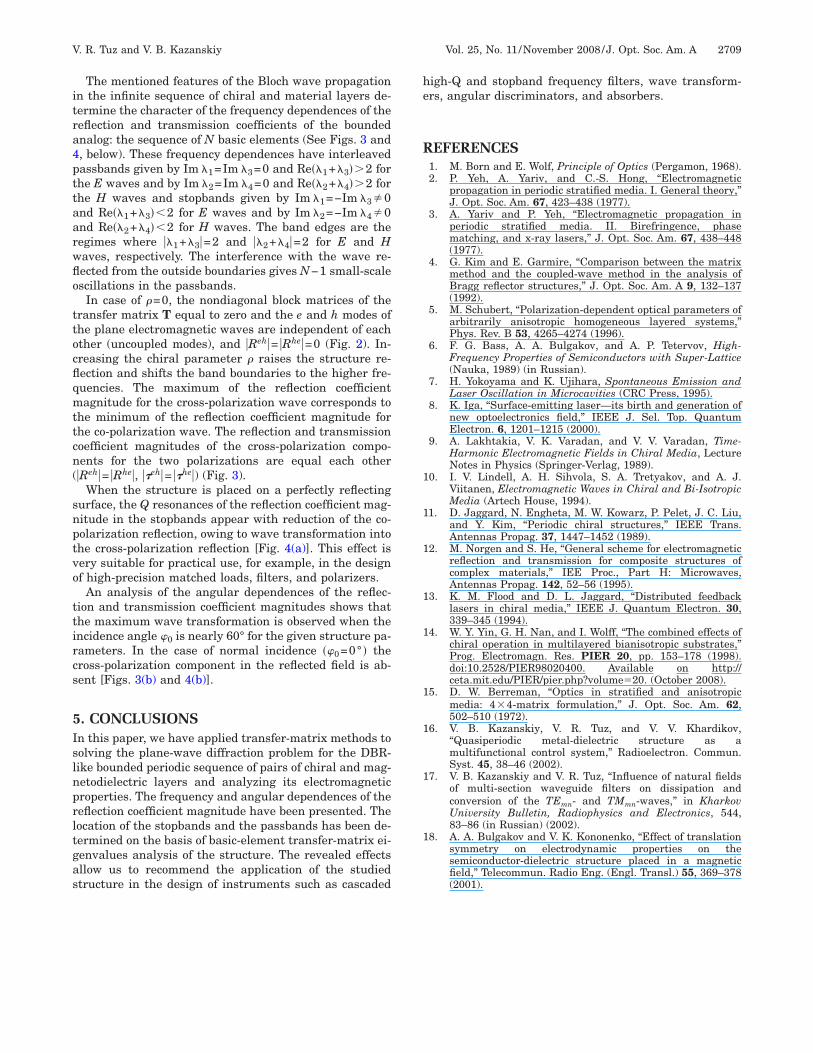
itra4pttaarwflo
ttocflqmttcn(
snptvo
ttircs
5Islnprltgas
he
R
1
1
1
1
1
1
1
1
1
V. R. Tuz and V. B. Kazanskiy Vol. 25, No. 11 /November 2008 /J. Opt. Soc. Am. A 2709
The mentioned features of the Bloch wave propagationn the infinite sequence of chiral and material layers de-ermine the character of the frequency dependences of theeflection and transmission coefficients of the boundednalog: the sequence of N basic elements (See Figs. 3 and, below). These frequency dependences have interleavedassbands given by Im �1=Im �3=0 and Re��1+�3��2 forhe E waves and by Im �2=Im �4=0 and Re��2+�4��2 forhe H waves and stopbands given by Im �1=−Im �3�0nd Re��1+�3��2 for E waves and by Im �2=−Im �4�0nd Re��2+�4��2 for H waves. The band edges are theegimes where ��1+�3�=2 and ��2+�4�=2 for E and Haves, respectively. The interference with the wave re-ected from the outside boundaries gives N−1 small-scalescillations in the passbands.
In case of �=0, the nondiagonal block matrices of theransfer matrix T equal to zero and the e and h modes ofhe plane electromagnetic waves are independent of eachther (uncoupled modes), and �Reh�= �Rhe�=0 (Fig. 2). In-reasing the chiral parameter � raises the structure re-ection and shifts the band boundaries to the higher fre-uencies. The maximum of the reflection coefficientagnitude for the cross-polarization wave corresponds to
he minimum of the reflection coefficient magnitude forhe co-polarization wave. The reflection and transmissionoefficient magnitudes of the cross-polarization compo-ents for the two polarizations are equal each other
�Reh�= �Rhe�, ��eh�= ��he�) (Fig. 3).When the structure is placed on a perfectly reflecting
urface, the Q resonances of the reflection coefficient mag-itude in the stopbands appear with reduction of the co-olarization reflection, owing to wave transformation intohe cross-polarization reflection [Fig. 4(a)]. This effect isery suitable for practical use, for example, in the designf high-precision matched loads, filters, and polarizers.
An analysis of the angular dependences of the reflec-ion and transmission coefficient magnitudes shows thathe maximum wave transformation is observed when thencidence angle �0 is nearly 60° for the given structure pa-ameters. In the case of normal incidence ��0=0° � theross-polarization component in the reflected field is ab-ent [Figs. 3(b) and 4(b)].
. CONCLUSIONSn this paper, we have applied transfer-matrix methods toolving the plane-wave diffraction problem for the DBR-ike bounded periodic sequence of pairs of chiral and mag-etodielectric layers and analyzing its electromagneticroperties. The frequency and angular dependences of theeflection coefficient magnitude have been presented. Theocation of the stopbands and the passbands has been de-ermined on the basis of basic-element transfer-matrix ei-envalues analysis of the structure. The revealed effectsllow us to recommend the application of the studiedtructure in the design of instruments such as cascaded
igh-Q and stopband frequency filters, wave transform-rs, angular discriminators, and absorbers.
EFERENCES1. M. Born and E. Wolf, Principle of Optics (Pergamon, 1968).2. P. Yeh, A. Yariv, and C.-S. Hong, “Electromagnetic
propagation in periodic stratified media. I. General theory,”J. Opt. Soc. Am. 67, 423–438 (1977).
3. A. Yariv and P. Yeh, “Electromagnetic propagation inperiodic stratified media. II. Birefringence, phasematching, and x-ray lasers,” J. Opt. Soc. Am. 67, 438–448(1977).
4. G. Kim and E. Garmire, “Comparison between the matrixmethod and the coupled-wave method in the analysis ofBragg reflector structures,” J. Opt. Soc. Am. A 9, 132–137(1992).
5. M. Schubert, “Polarization-dependent optical parameters ofarbitrarily anisotropic homogeneous layered systems,”Phys. Rev. B 53, 4265–4274 (1996).
6. F. G. Bass, A. A. Bulgakov, and A. P. Tetervov, High-Frequency Properties of Semiconductors with Super-Lattice(Nauka, 1989) (in Russian).
7. H. Yokoyama and K. Ujihara, Spontaneous Emission andLaser Oscillation in Microcavities (CRC Press, 1995).
8. K. Iga, “Surface-emitting laser—its birth and generation ofnew optoelectronics field,” IEEE J. Sel. Top. QuantumElectron. 6, 1201–1215 (2000).
9. A. Lakhtakia, V. K. Varadan, and V. V. Varadan, Time-Harmonic Electromagnetic Fields in Chiral Media, LectureNotes in Physics (Springer-Verlag, 1989).
0. I. V. Lindell, A. H. Sihvola, S. A. Tretyakov, and A. J.Viitanen, Electromagnetic Waves in Chiral and Bi-IsotropicMedia (Artech House, 1994).
1. D. Jaggard, N. Engheta, M. W. Kowarz, P. Pelet, J. C. Liu,and Y. Kim, “Periodic chiral structures,” IEEE Trans.Antennas Propag. 37, 1447–1452 (1989).
2. M. Norgen and S. He, “General scheme for electromagneticreflection and transmission for composite structures ofcomplex materials,” IEE Proc., Part H: Microwaves,Antennas Propag. 142, 52–56 (1995).
3. K. M. Flood and D. L. Jaggard, “Distributed feedbacklasers in chiral media,” IEEE J. Quantum Electron. 30,339–345 (1994).
4. W. Y. Yin, G. H. Nan, and I. Wolff, “The combined effects ofchiral operation in multilayered bianisotropic substrates,”Prog. Electromagn. Res. PIER 20, pp. 153–178 (1998).doi:10.2528/PIER98020400. Available on http://ceta.mit.edu/PIER/pier.php?volume�20. (October 2008).
5. D. W. Berreman, “Optics in stratified and anisotropicmedia: 4�4-matrix formulation,” J. Opt. Soc. Am. 62,502–510 (1972).
6. V. B. Kazanskiy, V. R. Tuz, and V. V. Khardikov,“Quasiperiodic metal-dielectric structure as amultifunctional control system,” Radioelectron. Commun.Syst. 45, 38–46 (2002).
7. V. B. Kazanskiy and V. R. Tuz, “Influence of natural fieldsof multi-section waveguide filters on dissipation andconversion of the TEmn- and TMmn-waves,” in KharkovUniversity Bulletin, Radiophysics and Electronics, 544,83–86 (in Russian) (2002).
8. A. A. Bulgakov and V. K. Kononenko, “Effect of translationsymmetry on electrodynamic properties on thesemiconductor-dielectric structure placed in a magneticfield,” Telecommun. Radio Eng. (Engl. Transl.) 55, 369–378(2001).
Copyright © 2022 FDOKUMEN