department of public works - Merced County
598
DEPARTMENT OF PUBLIC WORKS ADMINISTRATION DIVISION 345 West 7 th Street Merced, CA 95341 Telephone (209) 385-7601 Fax (209) 722-7690 Merced Veterans Hall HVAC Replacement 939 W. Main Street Merced, CA 95340 BID SET NO: _________________ BID DATE: Friday, March 27, 2020 at 3:00pm
-
Upload
khangminh22 -
Category
Documents
-
view
0 -
download
0
Transcript of department of public works - Merced County

DEPARTMENT OF PUBLIC WORKS ADMINISTRATION DIVISION
345 West 7th Street
Merced, CA 95341
Telephone (209) 385-7601
Fax (209) 722-7690
Merced Veterans Hall
HVAC Replacement
939 W. Main Street
Merced, CA 95340
BID SET NO: _________________
BID DATE: Friday, March 27, 2020 at 3:00pm

Specifications Prepared February 2020
TABLE OF CONTENTS
Merced County Department of Public Works Administration
HVAC Replacement Merced Veterans Hall
TABLE OF CONTENTS
INTRODUCTORY INFORMATION PAGES
000101 PROJECT TITLE PAGE ................................................................................................................ 1
000110 TABLE OF CONTENTS ................................................................................................................ 4
DIVISION 00 CONTRACT REQUIREMENTS PAGES
00010 INVITATION TO BID ..................................................................................................................... 2
00020 ABBREVIATIONS ......................................................................................................................... 2
00100 INSTRUCTIONS TO BIDDERS..................................................................................................... 6
00300 BID FORM ..................................................................................................................................... 4
00400 LIST OF SUBCONTRACTORS ..................................................................................................... 2
00500 STANDARD FORM OF AGREEMENT BETWEEN OWNER AND CONTRACTOR ..................... 11
00505 APPENDIX "A", DAVIS-BACON WAGE RATES (FEDERAL WAGE RATES) .............................. 1
00508 PAYROLL SUBMITTAL INFORMATION ....................................................................................... 1
00509 WAIVER AND RELEASE SUBMITTAL INFORMATION ............................................................... 5
00600 PAYMENT BOND .......................................................................................................................... 2
00610 PERFORMANCE BOND ............................................................................................................... 2
00700 GENERAL CONDITIONS OF THE CONTRACT FOR CONSTRUCTION .................................... 24
00800 SUPPLEMENTARY CONDITIONS ............................................................................................... 14
DIVISION 01 GENERAL REQUIREMENTS PAGES
011100 SUMMARY OF WORK .................................................................................................................. 4
011105 USE OF ARCHITECT’S ELECTRONIC FILES ............................................................................. 3
012500 SUBSTITUTION PROCEDURES .................................................................................................. 6
012600 CONTRACT MODIFICATION PROCEDURES………………………………………………………... 4
012613 REQUEST FOR INFORMATION………………………………………………………………………. . 5
013300 SUBMITTAL PROCEDURES ........................................................................................................ 10
015000 TEMPORARY FACILITIES AND CONTROLS .............................................................................. 9
015116 FIRE SAFETY DURING CONSTRUCTION…………………………………………………………… 7
016000 PRODUCT REQUIREMENTS ....................................................................................................... 5
017300 EXECUTION ................................................................................................................................. 8
017419 CONSTRUCTION WASTE MANAGEMENT AND DISPOSAL ...................................................... 16
017700 CLOSEOUT PROCEDURES ........................................................................................................ 5
017823 OPERATIONS AND MAINTENANCE DATA ................................................................................. 8
017836 WARRANTIES .............................................................................................................................. 3
017839 PROJECT RECORD DRAWINGS ................................................................................................ 3

Specifications Prepared February 2020
TABLE OF CONTENTS
Merced County Department of Public Works Administration
HVAC Replacement Merced Veterans Hall
DIVISION 02 EXISTING CONDITIONS PAGES
024119 SELECTIVE DEMOLITION ........................................................................................................... 7
DIVISION 03 CONCRETE PAGES
031512 POST INSTALLED CONCRETE ANCHORS ................................................................................ 6
DIVISION 04 MASONRY PAGES
(NOT USED)
DIVISION 05 METALS PAGES
055000 METAL FABRICATIONS ............................................................................................................... 10
055133 METAL LADDERS ........................................................................................................................ 4
DIVISION 06 WOOD AND PLASTICS PAGES
061000 ROUGH CARPENTRY .................................................................................................................. 8
061053 MISCELLANEOUS ROUGH CARPENTRY .................................................................................. 7
061600 SHEATHING ................................................................................................................................. 3
DIVISION 07 THERMAL AND MOISTURE PROTECTION PAGES
070150 MEMBRANE REROOFING PREPARATION ................................................................................ 4
076200 SHEET METAL FLASHING AND TRIM ........................................................................................ 5
079200 JOINT SEALANTS ........................................................................................................................ 7
DIVISION 08 DOORS AND WINDOWS PAGES
(NOT USED)
DIVISION 09 FINISHES PAGES
092216 NON-STRUCTURAL METAL FRAMING ....................................................................................... 5
092900 GYPSUM BOARD ......................................................................................................................... 8
099100 PAINTING ..................................................................................................................................... 17
DIVISIONS 10 - 20 PAGES
(NOT USED)

Specifications Prepared February 2020
TABLE OF CONTENTS
Merced County Department of Public Works Administration
HVAC Replacement Merced Veterans Hall
DIVISION 21 FIRE SUPPRESSION PAGES
(NOT USED)
DIVISION 22 PLUMBING PAGES
220000 GENERAL PLUMBING PROVISIONS .......................................................................................... 10
220050 PLUMBING.................................................................................................................................... 12
DIVISION 23 MECHANICAL/PLUMBING PAGES
230500 COMMON WORK RESULTS FOR HVAC .................................................................................... 7
230513 COMMON MOTOR REQUIREMENTS FOR HVAC EQUIPMENT ................................................ 3
230529 HANGERS & SUPPORTS FOR HVAC PIPING & EQUIPMENT .................................................. 7
230548 VIBRATION & SEISMIC CONTROLS FOR HVAC PIPING & EQUIPMENT ................................. 5
230553 IDENTIFICATION FOR HVAC PIPING & EQUIPMENT................................................................ 4
230593 TESTING ADJUSTMENT BALANCE FOR HVAC ........................................................................ 11
230700 HVAC INSULATION ...................................................................................................................... 19
230800 COMMISSIONING OF HVAC ....................................................................................................... 5
230900 BUILDING AUTOMATION SYSTEM ............................................................................................. 64
233113 METAL DUCTS ............................................................................................................................. 15
233300 AIR DUCT ACCESSORIES .......................................................................................................... 9
237413 PACKAGED OUTDOOR CENTRAL STATION AIR HANDLER UNITS ........................................ 10
DIVISION 25 INTEGRATED AUTOMATION PAGES
(NOT USED)
DIVISION 26 ELECTRICAL PAGES
260000 SUMMARY OF ELECTRICAL WORK ........................................................................................... 5
260100 GENERAL CONDITIONS FOR ELECTRICAL WORK .................................................................. 10
260500 BASIC ELECTRICAL MATERIALS AND METHODS .................................................................... 23
260100 GROUNDING ................................................................................................................................ 6
260500 SWITCHBOARDS ......................................................................................................................... 6
260100 PANELBOARDS ........................................................................................................................... 5
260500 ELECTRICAL ACCEPTANCE TESTS .......................................................................................... 13
DIVISION 27 COMMUNICATIONS PAGES
(NOT USED)
DIVISION 28 ELECTRONIC SAFETY AND SECURITY PAGES
(NOT USED)

Specifications Prepared February 2020
TABLE OF CONTENTS
Merced County Department of Public Works Administration
HVAC Replacement Merced Veterans Hall
DIVISION 31 EARTHWORK PAGES
312000 EARTHWORK ............................................................................................................................... 10
312222 SOIL MATERIALS ......................................................................................................................... 2
312333 TRENCH EXCAVATION AND BACKFILL ..................................................................................... 7
DIVISION 32 EXTERIOR IMPROVEMENTS PAGES
321216 ASPHALT PAVING ....................................................................................................................... 5
321313 SITE CONCRETE IMPROVEMENTS ........................................................................................... 4
321315 CONCRETE REINFORCEMENT .................................................................................................. 2
DIVISION 33 UTILITIES PAGES
(NOT USED)
APPENDIX TITLE PAGES
(NOT USED)
END OF SECTION

Specifications Prepared February 2020
INVITATION TO BID SECTION 00010 - Page 1
Merced County Department of Public Works Administration
HVAC Replacement Merced Veterans Hall
INVITATION TO BID SEALED BIDS will be received until 3:00 O'Clock P.M. Pacific Time on Friday, March 27, 2020, at the Administrative / Road Division Office for Public Works (located at 345 W. 7th Street, Building A, Merced, California) at which approximate time thereafter they will be publicly opened and their contents made known for the Merced County Administration Building Public Counter Security Upgrades, located at 2222 M Street, Merced, CA, County of Merced, California in accordance with the issued Drawings, Specifications and other Documents together with such Addenda thereto as may be issued prior to the bid opening.
In general, this project comprises: Removal of existing (4) evaporative coolers and (3) air conditioning mechanical equipment located on the roof and replacement with seven (7) new Package Gas/Electric units. Disconnect and abandon all existing mechanical equipment located in the basement per plans. Electrical utility upgrade as required to serve new mechanical equipment. Gas utility upgrade as required to serve new mechanical equipment. A mandatory pre-bid conference/job walk will be held at 10:00 O'Clock A.M. Pacific Time on Tuesday, March 3, 2020 at the Merced Veterans Hall, 939 W. Main Street, Merced. Requests for Information will be accepted until 3:00 O'Clock P.M. Pacific Time on Tuesday, March 17, 2020. Bids will be entered on a lump sum basis together with certain alternates. Drawings, Specifications, and other Documents are on file at the office of Department of Public Works, 345 West 7th Street, Merced, CA and at other designated locations, where copies may be examined free of charge. Documents may be obtained from the Department of Public Works, Administrative Division Offices, 345 West 7th Street, Building A, Merced, CA by intending Bidders for the Contract, who are licensed according to law, in digital format only (CD’s). THE BONDING ESTIMATE FOR THIS CONTRACT IS: $700,000.00 Drawings, Specifications and other Documents will be issued only to those Contractors whose valid license allows them to be the prime Contractor for this project. Others may examine the documents at the office of the Department of Public Works or at other designated locations. Bids, in order to receive consideration, shall be made and submitted in accordance with the requirements and conditions set forth in the Instructions to Bidders and in the aforesaid Drawings, Specifications and other Documents. Neither partial nor contingent Bids will be considered. The Bid of any Contractor who has previously violated the terms of the Federal Labor Laws, and who has not been cleared of such violations, will not be honored. Also, any Sub-Contractor under him under the same circumstance will not be accepted for this project. Contractor shall possess a valid Class B Contractors License at the time the contract is awarded. Pursuant to the provisions set forth in Sections 1770 to 1781, inclusive, and Sections 1810 to 1817, inclusive, of the Labor Code of the State of California, and local laws thereto applicable, the Board of Supervisors of Merced County, in the manner required by law, has ascertained the general prevailing Rate of Wages and also the hourly rates for Saturday, Sunday, Holiday and overtime work, in the locality where this work is to be performed, for each craft, classification and type of Workman or Mechanic needed to perform the work of this project, has adopted, by Resolution No. 79-38, and has published this wage scale in accordance with Sections 1773 and 1773.2 of the said

Specifications Prepared February 2020
INVITATION TO BID SECTION 00010 - Page 2
Merced County Department of Public Works Administration
HVAC Replacement Merced Veterans Hall
Labor Code, which scale will become a part of the Contract. A copy of this wage scale may also be obtained from the Office of the County Clerk of Merced County or at the following Web Site: www.dir.ca.gov/dlsr. It shall be mandatory upon the Contractor to whom the Contract is awarded, and upon all Sub-Contractors under him, to ascertain and pay not less than the latest general prevailing rate of wages and to pay not less than the general prevailing hourly rates for Saturday, Sunday, Holiday and overtime work for each Workman or Mechanic employed in the execution of the work of this project. Contractors may substitute an Escrow Agreement for performance retention in accordance with the State of California Public Contract Code Section 22300. “No contractor or subcontractor may be listed on a bid proposal for this project unless registered with the Department of Industrial Relations pursuant to Labor Code Section 1725.5 (with limited exceptions from this requirement for bid purposes only under Labor Code Section 1771.1 (a)). No contractor or subcontractor may be awarded a contract for this project unless registered with the Department of Industrial Relations pursuant to Labor Code Section 1725.5. This project is subject to compliance monitoring and enforcement by the Department of Industrial Relations.” Bid Security in the amount of ten (10) percent of the Bid amount (Base Bid plus Alternate Bids) shall accompany the Bid, in accordance with the provisions set forth in the Instructions to Bidders. The Board of Supervisors of Merced County reserves the right to reject any or all bids, to accept the Base Bid alone or together with any or all Alternates, and to waive any informalities or irregularities in any Bid or in the Bidding. By order of the Board of Supervisors of Merced County, Merced, California. _____________________________________ DANA S. HERTFELDER, DIRECTOR DEPARTMENT OF PUBLIC WORKS
END OF SECTION

Specifications Prepared February 2020
ABBREVIATIONS SECTION 00020 – Page 1
Merced County Department of Public Works Administration
HVAC Replacement Merced Veterans Hall
ABBREVIATIONS OF STANDARDS NOTE: Standards for the following Technical Societies, Organizations, Agencies, and Codes, to which reference is made, shall be as latest amended, unless otherwise indicated. AAMA Architectural Aluminum Manufacturers Association
AASHO American Association of State Highway Officials
ACI American Concrete Institute
AGA American Gas Association Laboratories
AIEE American Institute of Electrical Engineers
AISC American Institute of Steel Construction, Inc.
AISI American Iron and Steel Institute
AITC American Institute of Timber Construction
AMCA Air Moving and Conditioning Association, Inc.
ANSI American National Standards Institute, Inc. (formerly USAS and ASA)
API American Petroleum Institute
ARI Air Conditioning and Refrigeration Institute
ASHRAE American Society of Heating, Refrigerating and Air Conditioning Engineers, Inc.
ASME American Society of Mechanical Engineer
ASTM American Society for Testing and Materials
AWPA American Wood Preservers' Association
AWPI American Wood Preservers' Institute
AWS American Welding Society, Inc.
AWWA American Water Works Association, Inc.
CS Commercial Standards (U.S. Department of Commerce, National Bureau of Standards)
DFPA Douglas Fir Plywood Association
F.S. Federal Specifications
GSA-FSS Federal Service Administration - Federal Supply Services
IES Illuminating Engineering Society
MFMA Maple Flooring Manufacturers Association
MBFU National Board of Fire Underwriters
NEC National Electrical Code

Specifications Prepared February 2020
ABBREVIATIONS SECTION 00020 – Page 2
Merced County Department of Public Works Administration
HVAC Replacement Merced Veterans Hall
NEMA National Electrical Manufacturers Association
NFPA National Fire Protection Association
NTMA National Terrazzo & Mosaic Association
NWMA National Woodwork Manufacturers Association
OAC Office of Architecture and Construction (State of California)
OSHA Occupational Safety and Health Act
PCA Portland Cement Association
PCI Prestressed Concrete Institute
PS Product Standards (U.S. Department of Commerce, National Bureau of Standards)
PUC Public Utilities Commission
RIS Redwood Inspection Service
SDI Steel Door Institute
SMACNA Sheet Metal and Air Conditioning Contractors National Association, Inc.
APR Simplified Practice Recommendations (U.S. Department of Commerce, National Bureau of Standards)
TCA Tile Council of American, Inc.
TITLE 8 California Administrative Code, Division of Industrial Safety of the Department of Industrial Relations
TITLE 17 California Administrative Code, Group 2, Sub-Group 2, "Requirements for Hospital Construction"
TITLE 19 California Administrative Code, "Rules and Regulations of State Fire Marshal" (Public Safety)
TITLE 21 California Administrative Code, Sub-Chapter 1 of Chapter 1, "Public Works"
TITLE 24 California Administrative Code, "Building Standards"
UL Underwriters Laboratories, Inc.
UBC Uniform Building Code (Applicable Edition) of the Pacific Coast Building Officials Conference
USA United States of America Standards Institute (Now ANSI)
WCLA West Coast Lumbermen's Association
WCLB (WCLIB) West Coast Lumber Inspection Bureau
WIC Woodwork Institute of California
WUESSC Western Utilities Electric Service Standardization Committee
WWPA Western Wood Products Associates
END OF SECTION

Specifications Prepared February 2020
INSTRUCTIONS TO BIDDERS SECTION 00100 - Page 1
Merced County Department of Public Works Administration
HVAC Replacement Merced Veterans Hall
INSTRUCTIONS TO BIDDERS In order to receive consideration, Bids shall be prepared and submitted with conformity to the following instructions: A. PREPARATION OF BID:
1. Bid Form:
i. Bids shall be submitted only upon the Bid Form (or an exact copy thereof) furnished by or obtained from the Department of Public Works, and shall be based upon the Department's Drawings, Specifications, and other Documents.
ii. A sample copy of this form is bound in this Project Manual for bidding information, but it shall not be removed.
iii. Bids or modifications thereof submitted orally or by telephone or telegraph will not be considered.
2. Alternates:
i. Spaces for Alternate Bids shall not be left blank but shall state the price or "no charge," as may be applicable.
ii. Otherwise, spaces for Alternate Bids that are left blank will be interpreted as "no charge" in price.
iii. Additive and/or Deductive Alternate Bids will be considered respectively as added to and/or deducted from the Base Bid and will not be considered as Bids separate from the Base Bid.
iv. Alternate Bids other than those specifically called for will not be considered.
3. Execution:
i. Bids shall be properly and fully executed and signed in ink in longhand.
ii. Numbers shall be stated both in writing and in figures.
iii. Bids shall not contain erasures or alterations unless explained or noted over the signature, or signed initials, of the name of the Bidder signing the Bid.
iv. Bids containing any insertions, deletions, limitations, or conditions, made by the Bidder, or containing unexplained erasures or alterations, or items not called for, or irregularities of any kind may be rejected by Owner as being incomplete or irregular bids.
4. Signatures:
i. Bids by partnerships shall be signed in the partnership name by one of the partners followed by the designation "Partner."
ii. Bids by corporations shall be signed with the legal name of the corporation, followed by the name of the State of incorporation and by the signature and title of the President, Secretary or other Officer authorized to bind it in the matter, and with the corporate seal affixed thereto. When requested by the Owner, satisfactory evidence of the authority of the Officer signed in behalf of the corporation shall be furnished.
iii. A Bid submitted by a joint-venture shall be signed by the parties to it, with each party's signature being in accordance with the requirements set forth herein for non-joint-ventures.
iv. When a bid is signed by an Agent of an individual, partnership, or corporation, other than an authorized Officer of a corporation, a power-of-attorney of the Agent signing shall accompany the Bid.
v. Signatures of all persons signing by in longhand.

Specifications Prepared February 2020
INSTRUCTIONS TO BIDDERS SECTION 00100 - Page 2
Merced County Department of Public Works Administration
HVAC Replacement Merced Veterans Hall
5. State Contractor's License:
i. The name of the Bidder shall be accompanied by his valid State Contractors license number. For joint-ventures this shall be a separate license issued by the Contractor's State Licensing Board for this specific project.
B. SUBMITTAL OF BID:
1. Bids shall be sealed in an envelope plainly marked "BID FOR Merced Veterans Hall HVAC Replacement" and marked with the "BID OPENING DATE AND TIME" (to avoid premature opening) and shall be delivered to the place designated in the "Invitation to Bid" not later than the day and hour set forth therein for the opening of Bids. It shall be the sole responsibility of the Bidder to see that his Bid is received in the designated place by the stipulated date and time.
2. Bidders are hereby notified that pursuant to SB854 (Stat. 2014, Chapter 26):
i. No contractor or subcontractor may be listed on a bid proposal for a public works project (submitted on or after March 1, 2015) unless registered with the Department of Industrial Relations pursuant to Labor Code Section 1725.5 [with limited exceptions from this requirement for bid purposes only under Labor Code Section 1771.1(a)].
ii. No contractor or subcontractor may be awarded a contract for public work on a public works project (awarded on or after April 1, 2015) unless registered with the Department of Industrial Relations pursuant to Labor Code Section 1725.5.
iii. This project is subject to compliance monitoring and enforcement by the Department of Industrial Relations.
C. WITHDRAWAL OF BIDS:
1. Methods of Withdrawal: Any Bid may be withdrawn, or a revised Bid may be substituted for the withdrawn Bid, by a Bidder only upon his written or telegraphic request (but not by telephone) provided that it is received prior to the hour established for the opening of Bids but not thereafter. It shall be the Bidder's sole responsibility to see that such written or telegraphic request is received within the established time by the person or Agency designated to receive the Bids.
2. Written withdrawals may be delivered personally to the office or person responsible for the receipt of Bids, prior to the hour established for the opening of Bids, signed by the person who has signed the Bid.
3. Telegraphic withdrawals will only be honored upon receipt of written confirmation, signed by the Bidder, placed in the mail and post-marked prior to the time set for bid opening and if such confirmation is received within five (5) calendar days after bid opening.
4. Time Limit for Withdrawal: A Bidder may not withdraw his Bid for a period of thirty (30) calendar days after the date set for the opening of Bids, or for such agreed extension of time thereto as may be subsequently agreed upon in writing between the Owner and the lowest responsible Bidder.
5. Withdrawal Due to Bidding Error: In the event that a Bidder claims, after bid opening, that his Bid contains inadvertent clerical errors he may make written request to the Owner, for his consideration, to withdraw (but not to modify) his Bid.
6. This procedure shall be as provided, and within the time limits set forth in California Law (Section 5100 Public Contract Code).
D. INTERPRETATION OF DRAWINGS, DOCUMENTS, AND MODIFICATIONS:

Specifications Prepared February 2020
INSTRUCTIONS TO BIDDERS SECTION 00100 - Page 3
Merced County Department of Public Works Administration
HVAC Replacement Merced Veterans Hall
1. Should a Bidder be in doubt as to the true meaning of any item in the Drawings, Specifications, or other Documents, or should he discover items therein containing error, discrepancies or omissions, he shall immediately notify the Architect.
2. If found necessary, interpretation, clarification, deletions, additions, or correction will be made by written and/or graphic Addendum or Addenda, copy of which will be sent to each Bidder.
3. NO BIDDER SHALL RELY UPON ANY ORAL INTERPRETATION OR INSTRUCTION.
4. The Owner reserves the right to amend or revise the Drawings, Specifications and other documents, as his interests may require, by Addenda issued prior to the time set for opening of Bids.
E. ADDENDA:
1. All Addenda issued during the bidding period shall be included in the Bid and, in executing a Contract, they will become a part thereof.
2. Addenda will not be issued during the three (3) days prior to the time established for opening of Bids.
3. It shall be the Bidder's responsibility to make inquiry as to Addenda issued. Receipt of all Addenda issued shall be acknowledged by the Bidder by inserting the number of each Addenda received on the Bid Form in the space indicated therefore. Bidders shall be bound by all Addenda.
F. OPENING OF BIDS:
1. Bids will be opened, and their contents made public, at the place and the time set forth in the "Invitation to Bid."
2. The officer or person whose duty it is to open the Bids will ascertain and decide when the specified time has arrived, and no Bid received thereafter will be considered.
3. Bidders, or their authorized representatives, are invited to be present at the opening of Bids.
4. No responsibility will attach to an officer or agent of the Owner for the premature opening of an improperly identified bid envelope.
G. AWARD OF CONTRACT:
1. The award of the Contract, if awarded, will be to the lowest responsible Bidder complying with these instructions and other prescribed requirements and if its acceptance is in the Owner's best interest, and will be made within the time limit stipulated herein under "Withdrawal of Bids."
2. The Owner reserves the right to reject any or all Bids, to accept the Base Bid alone or together with any or all Alternates, and to waive informalities or irregularities in any Bid or in the Bidding.
H. LIST OF SUBCONTRACTORS:
1. Bids shall be accompanied by a List of Sub-Contractors that the Bidder proposes to use on this work. Their names, basic trade designation, California Contractors License Number and principal business location shall be submitted on this form, (or an exact copy thereof) furnished by or obtained from the office of the Architect.
2. A sample copy of this form is bound in the Project Manual for bidding information but it shall not be removed.
I. BID SECURITY:
1. Forms of Security: Bids shall be accompanied by a Bid Security of not less than 10% percent (10%) of the total amount of the Bid, made payable to the Owner. At the option of the Bidder, this may be a certified check, cashier's check, or Bid Bond.
2. Cash deposits will not be accepted.
Specifications Prepared February 2020
INSTRUCTIONS TO BIDDERS SECTION 00100 - Page 4
Merced County Department of Public Works Administration
HVAC Replacement Merced Veterans Hall
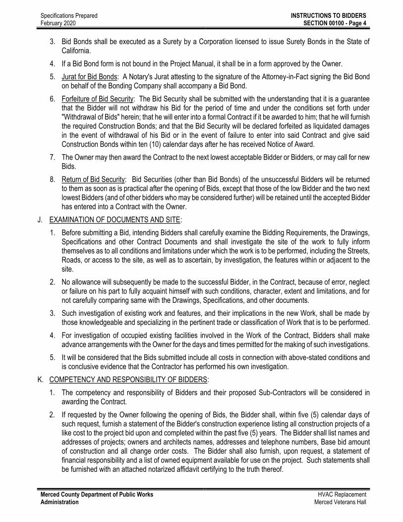
3. Bid Bonds shall be executed as a Surety by a Corporation licensed to issue Surety Bonds in the State of California.
4. If a Bid Bond form is not bound in the Project Manual, it shall be in a form approved by the Owner.
5. Jurat for Bid Bonds: A Notary's Jurat attesting to the signature of the Attorney-in-Fact signing the Bid Bond on behalf of the Bonding Company shall accompany a Bid Bond.
6. Forfeiture of Bid Security: The Bid Security shall be submitted with the understanding that it is a guarantee that the Bidder will not withdraw his Bid for the period of time and under the conditions set forth under "Withdrawal of Bids" herein; that he will enter into a formal Contract if it be awarded to him; that he will furnish the required Construction Bonds; and that the Bid Security will be declared forfeited as liquidated damages in the event of withdrawal of his Bid or in the event of failure to enter into said Contract and give said Construction Bonds within ten (10) calendar days after he has received Notice of Award.
7. The Owner may then award the Contract to the next lowest acceptable Bidder or Bidders, or may call for new Bids.
8. Return of Bid Security: Bid Securities (other than Bid Bonds) of the unsuccessful Bidders will be returned to them as soon as is practical after the opening of Bids, except that those of the low Bidder and the two next lowest Bidders (and of other bidders who may be considered further) will be retained until the accepted Bidder has entered into a Contract with the Owner.
J. EXAMINATION OF DOCUMENTS AND SITE:
1. Before submitting a Bid, intending Bidders shall carefully examine the Bidding Requirements, the Drawings, Specifications and other Contract Documents and shall investigate the site of the work to fully inform themselves as to all conditions and limitations under which the work is to be performed, including the Streets, Roads, or access to the site, as well as to ascertain, by investigation, the features within or adjacent to the site.
2. No allowance will subsequently be made to the successful Bidder, in the Contract, because of error, neglect or failure on his part to fully acquaint himself with such conditions, character, extent and limitations, and for not carefully comparing same with the Drawings, Specifications, and other documents.
3. Such investigation of existing work and features, and their implications in the new Work, shall be made by those knowledgeable and specializing in the pertinent trade or classification of Work that is to be performed.
4. For investigation of occupied existing facilities involved in the Work of the Contract, Bidders shall make advance arrangements with the Owner for the days and times permitted for the making of such investigations.
5. It will be considered that the Bids submitted include all costs in connection with above-stated conditions and is conclusive evidence that the Contractor has performed his own investigation.
K. COMPETENCY AND RESPONSIBILITY OF BIDDERS:
1. The competency and responsibility of Bidders and their proposed Sub-Contractors will be considered in awarding the Contract.
2. If requested by the Owner following the opening of Bids, the Bidder shall, within five (5) calendar days of such request, furnish a statement of the Bidder's construction experience listing all construction projects of a like cost to the project bid upon and completed within the past five (5) years. The Bidder shall list names and addresses of projects; owners and architects names, addresses and telephone numbers, Base bid amount of construction and all change order costs. The Bidder shall also furnish, upon request, a statement of financial responsibility and a list of owned equipment available for use on the project. Such statements shall be furnished with an attached notarized affidavit certifying to the truth thereof.

Specifications Prepared February 2020
INSTRUCTIONS TO BIDDERS SECTION 00100 - Page 5
Merced County Department of Public Works Administration
HVAC Replacement Merced Veterans Hall
L. COMPETENCY OF SUPERINTENDENT
1. If requested by the owner following the opening of Bids, the Contractor shall, within five (5) calendar days of such request, furnish a resume or statement of experience of the Superintendent or Foremen and all assistant Superintendents or Foremen that he proposes to use on this project.
i. The Superintendent's and assistant's resume shall include a list of all construction projects worked on in the past five (5) years.
ii. Superintendent and assistant(s) shall attend the preconstruction meeting.
iii. The Superintendent shall be dedicated to this project and shall be full time on this project. Any time there is work being performed on this project, the Superintendent or his assistant(s) shall be on the job site.
iv. The Superintendent or assistant(s) shall not be removed nor substituted after the pre-construction meeting without 15 days written notice from the Prime Contractor and written approval by the Owner.
M. BONDS:
1. Within ten (10) days of the award of Contract, the Successful Bidder will be required to furnish, at his expense, a Labor and Material Payment Bond in an amount equal to one hundred percent (100%) of the Contract Price, and a Faithful Performance Bond in an amount equal to one hundred percent (100%) of the Contract Price.
2. Said Bonds shall be furnished as separate instruments, shall be in the Statutory form, and shall contain or embrace the statutory obligations in accordance with the law of the State in which the Project is located. Said bonds shall be in the form bound in the Project Manual. If said bond forms are not bound in the Project Manual, then the Bonds shall be on forms satisfactory to the Owner. Bonds shall be issued by a Surety Company licensed to issue such Bonds in the State of California.
3. Additional requirements are set forth in the Supplementary Conditions.
N. INSURANCE:
1. The Successful Bidder will be required, for the life of the Contract, to carry and pay for the cost of the types and amounts of insurance as set forth in the GENERAL CONDITIONS OF THE CONTRACT and SUPPLEMENTARY CONDITIONS bound in this Project Manual.
O. NONDISCRIMINATION CLAUSES:
1. During the performance of this Contract, the contractor and its subcontractors shall not deny the Contract's benefits to any person on the basis of religion, color, ethnic group identification, sex, age, physical or mental disability, nor shall they discriminate unlawfully against any employee or applicant for employment because of race, religion, color, national origin, ancestry, physical handicap, mental disability, medical condition, marital status, age, or sex. Contractor shall insure that the evaluation and treatment of employees and applicants for employment are free of such discrimination.
2. Recipient contractor and its subcontractors shall give written notice of their obligations under the clause to labor organizations with which they have a collective bargaining or other agreement.
3. The contractor shall include the nondiscrimination and compliance provisions of this clause in all subcontracts to perform work under the contract.
P. CLEAN AIR ACT AND CLEAN WATER ACT:
1. Contract, subcontracts, and subgrants of amounts in excess of $100,000 shall contain a provision which requires compliance with all applicable standards, orders, or requirements issued under Section 306 of the

Specifications Prepared February 2020
INSTRUCTIONS TO BIDDERS SECTION 00100 - Page 6
Merced County Department of Public Works Administration
HVAC Replacement Merced Veterans Hall
Clean Air Act (42 USC 1857 (h)), Section 508 of the Clean Water Act (33 USC 1368), Executive Order 11738, and Environmental Protection Agency regulations (40 CFR, Part 15), which prohibit the use under non-exempt Federal contracts, grants or loans of facilities included on the EPA List of Violating Facilities. The provision shall require reporting of violations to the grantor agency and to the USEPA Assistance Administrator for Enforcement (EN-329).
END OF SECTION

Specifications Prepared February 2020
BID FORM SECTION 00300 – Page 1
Merced County Department of Public Works Administration
HVAC Replacement Merced Veterans Hall
BID FORM Bid For: Merced Veterans Hall HVAC Replacement located at 939 W. Main St, Merced, CA, Merced County,
California. Bid Date: Friday, March 27, 2020, at 3:00 O'Clock Pacific Time. Bid Place: Administrative Office for Public Works (located at 345 W. 7th Street, Building A, Merced, California
95341-6041). The Undersigned, in accordance with the "Instructions to Bidders", contained in the project manual, and in accordance with the Drawings, Specifications and other Documents hereby propose/s and agree/s to furnish and pay for all:
Labor, materials and equipment except as otherwise set forth. Construction equipment, tools, means, machinery and temporary facilities. Utilities required for construction. Permits and fees except as otherwise set forth. Bonds and insurance required. Sales, consumer and use taxes required by law. Transportation, facilities, services and other items as required or necessary for, and incidental to, the
prosecution and completion of the work of the project. The Undersigned agree/s that the work will be performed as set forth in, and in strict accordance with, the Drawings, Specifications, and other Contract Documents prepared by TETER, LLP for the following sum: BASE BID (everything included in the Contract Documents) FOR THE SUM OF: DOLLARS $ CONTRACT TIME: The Undersigned understand/s that the time for completion of the work of the Contract is 120 consecutive Calendar Days, subject to such authorized extensions as set forth in the "General Conditions of the Contract for Construction" included in the Project Manual. If awarded the Contract within thirty (30) calendar days after the date of the opening of Bids, or within such extension of time thereto as may be agreed upon in writing between the Owner and the lowest responsible Bidder the Undersigned hereby agree/s to sign the Contract, in the Form of Agreement bound in the Project Manual, furnish the required Construction Bonds within ten (10) calendar days after having been given notice to enter into the Contract, and to begin work within five (5) calendar days after having been given Notice to Proceed.

Specifications Prepared February 2020
BID FORM SECTION 00300 – Page 2
Merced County Department of Public Works Administration
HVAC Replacement Merced Veterans Hall
DAMAGES: The Undersigned understand/s that damages in the amount of five hundred dollars ($500) may be assessed against or recovered from the Contractor for each calendar day's delay beyond the time prescribed in completing the work of the Contract, under the conditions and for the reasons set forth in the form of Agreement bound in the Project Manual. EXAMINATION OF SITE AND DOCUMENTS: The Undersigned, in accordance with the detailed requirements set forth in the Instructions to Bidders, has carefully investigated the site of the proposed work and is familiar with the conditions pertaining and has carefully compared same with the Drawings, Specifications and other Documents and has included costs arising therefrom in the Bid. The Undersigned has carefully examined the Bidding Requirements, Drawings, Specifications and other Documents and has full knowledge of the kind, quantities and quality of the work required, has carefully checked the bid prices set forth herein and agree(s) that the Owner will not be responsible for any errors or omissions on the part of the Undersigned in making up this Bid. BID GUARANTY: Enclosed, and as follows, find Bid Guaranty in the amount of Ten Percent (10%) of the Bid computed on the Base Bid. Bidder's Bond for $ , or Certified Check for $ , or Cashier's Check for $ . NON-COLLUSION The Undersigned hereby certified that this Bid is genuine and not collusive.

Specifications Prepared February 2020
BID FORM SECTION 00300 – Page 3
Merced County Department of Public Works Administration
HVAC Replacement Merced Veterans Hall
SUBMITTED BY:
NAME OF ORGANIZATION "A":
Type of Organization
Business Address
Signatures
JOINT VENTURE WITH "B":
Type of Organization
Business Address
Signatures
See "Instructions to Bidders" for exact signature requirements. Use legal name and exact type of organization (i.e., Corporation, Partnership, Company, Individual, Joint Venture). CONTRACTOR'S LICENSE #______________ State of _______________________________ CONTRACTOR'S LICENSE EXPIRATION DATE _____________________________________ (If a Joint Venture, insert the specific license number for this project.) The Contractor's License Number and expiration date stated herein are made under penalty of perjury. DIR Registration No. __________________, Expiration Date:____________________ ____________________________________ Contractor CORPORATE SEAL/S: ADDENDA: The following addendum/a has/have been received and is/are included in the Bid: No (s) .

Specifications Prepared February 2020
BID FORM SECTION 00300 – Page 4
Merced County Department of Public Works Administration
HVAC Replacement Merced Veterans Hall
STATEMENT OF COMPLIANCE (Company Name) (hereinafter referred to as "prospective contractor" ) hereby certified, unless specifically exempted, compliance with
Government Code Section 12990 and California Administrative Code, Title II, Division 4, Chapter 5 in matters relating
to the development, implementation and maintenance of a nondiscrimination program. Prospective contractor agrees
not to unlawfully discriminate against any employee or applicants for employment because of race, religion, color,
national origin, ancestry, physical handicap, medical condition, marital status, sex or age (over forty).
I, hereby swear that I am duly authorized to legally bind the prospective contractor to the above
described certification. I am fully aware that this certification executed on in the county of
is made under the penalty of perjury under the laws of the State of California.
Phone No.:
Signature Fax No.:
Title E-Mail Address:
END OF SECTION

Specifications Prepared February 2020
LIST OF SUBCONTRACTORS SECTION 00400 – Page 1
Merced County Department of Public Works Administration
HVAC Replacement Merced Veterans Hall
LIST OF SUBCONTRACTORS FORM
PURSUANT TO THE PROVISIONS SET FORTH IN TITLE I, DIVISION 5, CHAPTER 2 (Sections 4100-4113, inclusive) of the Public Contract Code of the State of California -- it is required that the Contractor set forth in his Bid the name and principal business address of each Subcontractor who will perform work or labor or render service to the Contractor on or about the construction. Vendors or suppliers of materials, only, are not required to be listed. If a Contractor fails to specify a Subcontractor for any portion of the work to be performed under the Contract, on or about the construction of the project, in excess of 1/2 of 1% of the Contractor's total Bid, he shall be deemed to have agreed to perform such portion himself, using his own resources and employed personnel and he shall not be permitted to sub-contract that portion of the work, except under the conditions set forth in Section 4107 of the Government Code of the State of California. Subcontractors shall not sublet their work as a whole. Should the Contractor violate any of the provisions of said Chapter, his so doing will be deemed a violation of his Contract and the awarding authority shall have the right to terminate the Contractor's control over the work. Upon any such violation, the Contractor may be subject to such penalties as are prescribed by Law. In the event of an inadvertent error in the California Contractor number is made for a subcontractor listed, such error shall not be grounds for filing a bid protest or grounds for considering a bid nonresponsive. The corrected license number must be submitted within 24 hours after bid opening and corrected contractor’s license number must correspond to the submitted name and location. If the prospective contractor fails to correct an inadvertent error for a listed subcontractor’s license number within the 24 hour time period, the Owner may find the bid nonresponsive. -The prospective contractor shall be solely responsible to correct any errors in the notation of the listed subcontractors California Contractor’s license number; -The prospective contractor must submit the corrected information via facsimile at (209) 722-7690, of hand deliver to 345 W. 7th Street Merced, CA 95341 to the Director of Public Works. -Failure to submit a corrected California Contractor’s license number in compliance with the process set forth above will cause the bid to be nonresponsive.
SUBCONTRACTOR LIST
Portion of Work_______________________________ Name__________________________________________
Address_____________________________________ California CSLB No._______________________________
DIR Registration No.___________________________ DIR Reg. No. Exp. Date___________________________
Portion of Work_______________________________ Name__________________________________________
Address_____________________________________ California CSLB No._______________________________
DIR Registration No.___________________________ DIR Reg. No. Exp. Date___________________________

Specifications Prepared February 2020
LIST OF SUBCONTRACTORS SECTION 00400 – Page 2
Merced County Department of Public Works Administration
HVAC Replacement Merced Veterans Hall
Portion of Work_______________________________ Name__________________________________________
Address_____________________________________ California CSLB No._______________________________
DIR Registration No.___________________________ DIR Reg. No. Exp. Date___________________________
Portion of Work_______________________________ Name__________________________________________
Address_____________________________________ California CSLB No._______________________________
DIR Registration No.___________________________ DIR Reg. No. Exp. Date___________________________
Portion of Work_______________________________ Name__________________________________________
Address_____________________________________ California CSLB No._______________________________
DIR Registration No.___________________________ DIR Reg. No. Exp. Date___________________________
Portion of Work_______________________________ Name__________________________________________
Address_____________________________________ California CSLB No._______________________________
DIR Registration No.___________________________ DIR Reg. No. Exp. Date___________________________
Portion of Work_______________________________ Name__________________________________________
Address_____________________________________ California CSLB No._______________________________
DIR Registration No.___________________________ DIR Reg. No. Exp. Date___________________________
Portion of Work_______________________________ Name__________________________________________
Address_____________________________________ California CSLB No._______________________________
DIR Registration No.___________________________ DIR Reg. No. Exp. Date___________________________
Portion of Work_______________________________ Name__________________________________________
Address_____________________________________ California CSLB No._______________________________
DIR Registration No.___________________________ DIR Reg. No. Exp. Date___________________________
Portion of Work_______________________________ Name__________________________________________

Specifications Prepared February 2020
LIST OF SUBCONTRACTORS SECTION 00400 – Page 3
Merced County Department of Public Works Administration
HVAC Replacement Merced Veterans Hall
Address_____________________________________ California CSLB No._______________________________
DIR Registration No.___________________________ DIR Reg. No. Exp. Date___________________________
Portion of Work_______________________________ Name__________________________________________
Address_____________________________________ California CSLB No._______________________________
DIR Registration No.___________________________ DIR Reg. No. Exp. Date___________________________
Portion of Work_______________________________ Name__________________________________________
Address_____________________________________ California CSLB No._______________________________
DIR Registration No.___________________________ DIR Reg. No. Exp. Date___________________________
Portion of Work_______________________________ Name__________________________________________
Address_____________________________________ California CSLB No._______________________________
DIR Registration No.___________________________ DIR Reg. No. Exp. Date___________________________
Portion of Work_______________________________ Name__________________________________________
Address_____________________________________ California CSLB No._______________________________
DIR Registration No.___________________________ DIR Reg. No. Exp. Date___________________________
Portion of Work_______________________________ Name__________________________________________
Address_____________________________________ California CSLB No._______________________________
DIR Registration No.___________________________ DIR Reg. No. Exp. Date___________________________
Portion of Work_______________________________ Name__________________________________________
Address_____________________________________ California CSLB No._______________________________
DIR Registration No.___________________________ DIR Reg. No. Exp. Date___________________________
END OF SECTION

Specifications Prepared February 2020
STANDARD FORM OF AGREEMENT SECTION 00500 – Page 0
Merced County Department of Public Works Administration
HVAC Replacement Merced Veterans Hall
STANDARD FORM OF AGREEMENT BETWEEN OWNER AND CONTRACTOR
AIA DOCUMENT A101 The following document consists of 11 pages

Specifications Prepared February 2020
DAVIS BACON WAGE RATES SECTION 00505 - Page 1
Merced County Department of Public Works Administration
HVAC Replacement Merced Veterans Hall
DAVIS BACON WAGE RATES
GENERAL DECISION: CA20030029 01/16/2004 CA29
Date: January 16, 2004
General Decision Number: CA20030029 01/16/2004
Superseded General Decision Number: CA020029
State: California
Construction Types: Building, Heavy (Heavy, and Dredging) and
Highway
Counties: Alameda, Calaveras, Contra Costa, Fresno, Kings,
Madera, Mariposa, Merced, Monterey, San Benito, San Francisco,
San Joaquin, San Mateo, Santa Clara, Santa Cruz, Stanislaus and
Tuolumne Counties in California.
BUILDING CONSTRUCTION PROJECTS; DREDGING PROJECTS (does not
include hopper dredge work); HEAVY CONSTRUCTION PROJECTS (does
not include water well drilling); HIGHWAY CONSTRUCTION PROJECTS
Modification Number Publication Date
0 06/13/2003
1 01/16/2004
ASBE0016-001 01/01/2003
Rates Fringes
Asbestos Workers/Insulator
Includes the
application of all
insulating materials,
Protective Coverings,
Coatings, and Finishes
to all types of
mechanical systems..........$ 37.58 9.96
----------------------------------------------------------------
ASBE0016-004 05/01/2002
Rates Fringes
Asbestos Removal
worker/hazardous material
handler
Includes preparation,
wetting, stripping,
removal, scrapping,
vacuuming, bagging and
disposing of all
insulation materials
from mechanical
systems, whether they
contain asbestos or not

Specifications Prepared February 2020
PAYROLL INFORMATION SECTION 00508 - Page 1
Merced County Department of Public Works Administration
HVAC Replacement Merced Veterans Hall
PAYROLL INFORMATION 1.1 INSTRUCTIONS:
A. UPON REQUEST THE GENERAL CONTRACTOR WILL PROVIDE THE COUNTY OR CONSTRUCTION MANAGER ANY RECORDS REQUESTED FOR PAYROLL ON THIS PROJECT WITHIN 48 HOURS INCLUDING BUT NOT LIMITED TO:
i. Name, Address, Social Security Number and Ethnic Code of Employee or Employees.
ii. Number of withholding exemptions.
iii. Work classification.
iv. Day, Date and Hours Worked
v. Total Hours.
vi. Rate of Pay.
vii. Gross Pay.
viii. Deductions
ix. Net Wages Paid
END OF SECTION

Specifications Prepared February 2020
WAIVER AND RELEASE SUBMITTAL INFORMATION SECTION 00509 - Page 1
Merced County Department of Public Works Administration
HVAC Replacement Merced Veterans Hall
WAIVER AND RELEASE SUBMITTAL INFORMATION 1.1 INSTRUCTIONS FOR WAIVER AND RELEASE (LIEN WAIVER) SUBMITTALS 1.1.1 GENERAL INSTRUCTIONS
.1 Waiver and Releases must be submitted on forms provided by County of Merced. Copies of
said forms comply with Civil Code 3262 are at the end of this Section.
.2 Comply with General Conditions Section 9.3.7. .3 Waiver and Release submittal sequence.
(a) Upon initial submittal for progress payment, submit for each subcontractor, material or
equipment supplier a "CONDITIONAL WAIVER AND RELEASE UPON PROGRESS PAYMENT". If initial submittal is also a final submittal for any or all subcontractors, material or equipment suppliers, submit a "CONDITIONAL WAIVER AND RELEASE UPON FINAL PAYMENT".
(b) Upon each subsequent submittal for progress payment, submit for each subcontractor,
material or equipment supplier a "CONDITIONAL WAIVER AND RELEASE UPON PROGRESS PAYMENT" for a total amount reflecting the current progress payment. Also submit an "UNCONDITIONAL WAIVER AND RELEASE UPON PROGRESS PAYMENT" reflecting the previous progress payment aggregate sum.
(c) Upon final submittal for progress payment, submit for each subcontractor, material or equipment supplier a "CONDITIONAL WAIVER AND RELEASE UPON FINAL PAYMENT". Also submit an "UNCONDITIONAL WAIVER AND RELEASE UPON PROGRESS PAYMENT" reflecting the previous progress payment aggregate sum.
(d) Prior to Final Completion and Final Payment, submit for each subcontractor, material or
equipment supplier an "UNCONDITIONAL WAIVER AND RELEASE UPON FINAL PAYMENT".
.4 Comply with General Conditions Section 9.8.2. END OF SECTION

Specifications Prepared February 2020
WAIVER AND RELEASE SUBMITTAL INFORMATION SECTION 00509 - Page 2
Merced County Department of Public Works Administration
HVAC Replacement Merced Veterans Hall
CONDITIONAL WAIVER AND RELEASE UPON PROGRESS PAYMENT Upon receipt by the undersigned of a check from
(Maker of Check) in the sum of $ payable to
(Amount of Check) (Payee or Payees of Check) and when the check has been properly endorsed and has been paid by the bank upon which it is drawn, this document shall become effective to release any mechanic's lien, stop notice, or bond right the undersigned has on the job of County Of Merced located at
(Owner) (Job Description) to the following extent. This release covers a progress payment for labor, services, equipment, or material furnished to through
(Your Customer) (Date) only and does not cover any retentions retained before or after the release date; extras furnished before the release date for which payment has not been received; extras or items furnished after the release date. Rights based upon work performed or items furnished under a written change order which has been fully executed by the parties prior to the release date are covered by this release unless specifically reserved by the claimant in this release. This release of any mechanic's lien, stop notice, or bond right shall not otherwise affect the contract right, including rights between parties to the contract based upon the rescission, abandonment, or breach of the contract, or the right of the undersigned to recover compensation for furnished labor, services, equipment, or material covered by this release if that furnished labor, services, equipment, or material was not compensated by the progress payment. Before any recipient of the document relies on it, said party should verify evidence of payment to the undersigned. DATE:
(Company Name) By:
(Signature) (Title)

Specifications Prepared February 2020
WAIVER AND RELEASE SUBMITTAL INFORMATION SECTION 00509 - Page 3
Merced County Department of Public Works Administration
HVAC Replacement Merced Veterans Hall
UNCONDITIONAL WAIVER AND RELEASE UPON PROGRESS PAYMENT The undersigned has been paid and has received a progress payment in the sum of $ for labor, services, equipment and/or material furnished to
(Your Customer) on the job of County Of Merced located at (Owner) (Job Description) and does hereby release any mechanic's lien, stop notice, or bond right that the undersigned has on the above referenced job to the following extent. This release covers a progress payment for labor, services, equipment and/or materials furnished to through only, and does not
(Your Customer) (Date) cover any retentions retained before or after the release date; extras furnished before the release date for which payment has not been received; extras or items furnished after the release date. Rights based upon work performed or items furnished under a written change order which has been fully executed by the parties prior to the release date are covered by this release unless specifically reserved by the claimant in this release. This release of any mechanic's lien, stop notice, or bond right shall not otherwise affect the contract rights, including rights between parties to the contract based upon rescission, abandonment, or breach of the contract, or the right of the undersigned to recover compensation for furnished labor, services, equipment, or material covered by this release if that furnished labor, services, equipment, or material was not compensated by the progress payment. DATE:
(Company Name) By:
(Signature) (Title)
NOTICE: THIS DOCUMENT WAIVES RIGHTS UNCONDITIONALLY AND STATES THAT YOU HAVE BEEN PAID FOR GIVING UP THOSE RIGHTS. THIS DOCUMENT IS ENFORCEABLE AGAINST YOU IF YOU SIGN IT, EVEN IF YOU HAVE NOT BEEN PAID. IF YOU HAVE NOT BEEN PAID, USE A CONDITIONAL RELEASE FORM.

Specifications Prepared February 2020
WAIVER AND RELEASE SUBMITTAL INFORMATION SECTION 00509 - Page 4
Merced County Department of Public Works Administration
HVAC Replacement Merced Veterans Hall
CONDITIONAL WAIVER AND RELEASE UPON FINAL PAYMENT Upon receipt by the undersigned of a check from
(Maker of Check) in the sum of $ payable to
(Amount of Check) (Payee or Payees of Check) and when the check has been properly endorsed and has been paid by the bank upon which it is drawn, this document shall become effective to release any mechanic's lien, stop notice, or bond right the undersigned has on the job of County Of Merced located at
(Owner) (Job Description) This release covers the final payment to the undersigned for all labor, services, equipment, or material furnished on the job, except for disputed claims for additional work in the amount of $ . Before any recipient of this document relies on it, the party should verify evidence of payment to the undersigned. DATE:
(Company Name) By:
(Signature) (Title)

Specifications Prepared February 2020
WAIVER AND RELEASE SUBMITTAL INFORMATION SECTION 00509 - Page 5
Merced County Department of Public Works Administration
HVAC Replacement Merced Veterans Hall
UNCONDITIONAL WAIVER AND RELEASE UPON FINAL PAYMENT The under signed has been paid in full for all labor, services, equipment or material furnished to on the job of County of Merced
(Your Customer) (Owner) located at and does
(Job Description) hereby waive and release any right to a mechanic's lien, stop notice, or any right against a labor and material bond on the job, except for disputed claims for extra work in the amount of $ DATE:
(Company Name) By:
(Signature) (Title) NOTICE: THIS DOCUMENT WAIVES RIGHTS UNCONDITIONALLY AND STATES THAT YOU HAVE BEEN PAID FOR GIVING UP THOSE RIGHTS. THIS DOCUMENT IS ENFORCEABLE AGAINST YOU IF YOU SIGN IT, EVEN IF YOU HAVE NOT BEEN PAID. IF YOU HAVE NOT BEEN PAID, USE A CONDITIONAL RELEASE FORM.
Specifications Prepared February 2020
PAYMENT BOND SECTION 00600 - Page 1
Merced County Department of Public Works Administration
HVAC Replacement Merced Veterans Hall
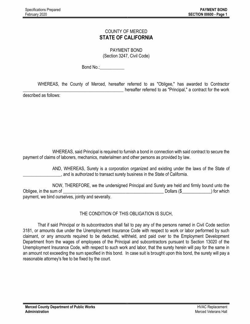
COUNTY OF MERCED
STATE OF CALIFORNIA
PAYMENT BOND (Section 3247, Civil Code)
Bond No.:___________ WHEREAS, the County of Merced, hereafter referred to as "Obligee," has awarded to Contractor _____________________________________________ hereafter referred to as "Principal," a contract for the work described as follows: WHEREAS, said Principal is required to furnish a bond in connection with said contract to secure the payment of claims of laborers, mechanics, materialmen and other persons as provided by law. AND, WHEREAS, Surety is a corporation organized and existing under the laws of the State of _________________, and is authorized to transact surety business in the State of California. NOW, THEREFORE, we the undersigned Principal and Surety are held and firmly bound unto the Obligee, in the sum of _____________________________________________ Dollars ($_____________) for which payment, we bind ourselves, jointly and severally.
THE CONDITION OF THIS OBLIGATION IS SUCH, That if said Principal or its subcontractors shall fail to pay any of the persons named in Civil Code section 3181, or amounts due under the Unemployment Insurance Code with respect to work or labor performed by such claimant, or any amounts required to be deducted, withheld, and paid over to the Employment Development Department from the wages of employees of the Principal and subcontractors pursuant to Section 13020 of the Unemployment Insurance Code, with respect to such work and labor, that the surety herein will pay for the same in an amount not exceeding the sum specified in this bond. In case suit is brought upon this bond, the surety will pay a reasonable attorney's fee to be fixed by the court.

Specifications Prepared February 2020
PAYMENT BOND SECTION 00600 - Page 2
Merced County Department of Public Works Administration
HVAC Replacement Merced Veterans Hall
This bond shall inure to the benefit of any of and all persons, companies, and corporations entitled to file claims under Civil Code Section 3181, so as to give a right of action to them or their assigns in any suit brought upon this bond. DATED: _________________
Correspondence or claims relating to this bond should be sent to the surety at the following address:
by
Principal
Surety
Attorney-in-Fact
NOTE: Signatures of those executing for the surety must be properly acknowledged and a power of attorney
attached.
CERTIFICATE OF ACKNOWLEDGMENT State of California ) SS County of Merced ) On this ______ day of ________________ in the year 20__ before me ________________________, personally appeared _________________________________, personally known to me (or proved to me on the basis of satisfactory evidence) to be the person whose name is subscribed to this instrument as the attorney-in-fact of _________________________ and acknowledged to me that he (she) subscribed the name of the said company thereto as surety, and his (her) own name as attorney-in-fact.
(SEAL)
NOTARY PUBLIC
END OF SECTION

Specifications Prepared February 2020
PERFORMANCE BOND SECTION 00610 – Page 1
Merced County Department of Public Works Administration
HVAC Replacement Merced Veterans Hall
COUNTY OF MERCED STATE OF CALIFORNIA
PERFORMANCE BOND
Bond No.:___________ WHEREAS, the County of Merced, hereafter referred to as "Obligee," has awarded to Contractor _____________________________________________ hereafter referred to as "Principal," a contract for the work described as follows: WHEREAS, said Principal is required to furnish a bond in connection with said contract, guaranteeing the faithful performance thereof. AND, WHEREAS, Surety is a corporation organized and existing under the laws of the State of _________________, and is authorized to transact surety business in the State of California. NOW, THEREFORE, we the undersigned Principal and Surety are held and firmly bound unto the Obligee, in the sum of _____________________________________________ Dollars ($_____________) to be paid to the Obligee, for which payment, we bind ourselves, jointly and severally.
THE CONDITION OF THIS OBLIGATION IS SUCH, That if said Principal shall faithfully perform his contract, then this obligation shall be null and void; otherwise it shall be in full force and effect.

Specifications Prepared February 2020
PERFORMANCE BOND SECTION 00610 – Page 2
Merced County Department of Public Works Administration
HVAC Replacement Merced Veterans Hall
No right of action shall accrue under this bond to or for the use of any person other than the Obligee named herein. DATED: _________________
Correspondence or claims relating to this bond should be sent to the surety at the following address:
by
Principal
Surety
Attorney-in-Fact
NOTE: Signatures of those executing for the surety must be properly acknowledged and a power of attorney
attached.
CERTIFICATE OF ACKNOWLEDGMENT State of California ) SS County of Merced ) On this ______ day of ________________ in the year 20__ before me ________________________, personally appeared _________________________________, personally known to me (or proved to me on the basis of satisfactory evidence) to be the person whose name is subscribed to this instrument as the attorney-in-fact of _________________________ and acknowledged to me that he (she) subscribed the name of the said company thereto as surety, and his (her) own name as attorney-in-fact.
(SEAL)
NOTARY PUBLIC
END OF SECTION

Specifications Prepared February 2020
GENERAL CONDITIONS OF CONTRACT SECTION 00700 – Page 0
Merced County Department of Public Works Administration
HVAC Replacement Merced Veterans Hall
GENERAL CONDITIONS OF THE CONTRACT FOR CONSTRUCTION
AIA DOCUMENT A201 The following document consists of 24 pages
SUPPLEMENTARY CONDITIONS The following supplements modify, change, delete from or add to the "General Conditions of the Contract for Construction", AIA Document A201, Fourteenth Edition, 1987. ARTICLE 1: GENERAL PROVISIONS 1.1.1 THE CONTRACT DOCUMENTS: Add the following at the end of 1.1.1:
The Faithful Performance Bond, Labor and Material Payment Bond, and List of Sub-Contractors, are also Contract Documents. The said Drawings and Specifications are those annexed hereto and as listed respectively in the Schedule of Drawings and Table of Contents bound in the Project Manual.
1.2 EXECUTION, CORRELATION AND INTENT

Specifications Prepared February 2020
GENERAL CONDITIONS OF CONTRACT SECTION 00700 – Page 0
Merced County Department of Public Works Administration
HVAC Replacement Merced Veterans Hall
1.2.2 Delete the word "visited" and substitute "investigated." Add the following at the end of 1.2.2: " -- and the Bidding Requirements." Add the following: 1.2.6 Work that is indicated on the Drawings in brief or outline form and that is not completely annotated shall be
equal to similar detailed or annotated work. Figured dimensions shall govern over scale. Work not dimensioned shall be referred to the Architect by the
Contractor for clarification. Add the following: 1.2.7 Standards for materials or processes specified by the number, symbol, or title of a specific Standard (such
as ASTM Standard, Federal Specification, a Trade Association Standard or other similar Standard) shall be in full force and effect as though printed in the Project Manual.
Copies of these Standards are not furnished herewith for the reason that the manufacturers and trades involved are assumed to be familiar with their requirements.
The Architect will furnish, upon request, information as to how copies of these Standards may be obtained. The requirements of the referenced Standards shall be construed as being in addition to, and not in lieu of such more stringent requirements as may be set forth in the Contract Drawings and Specifications.
Add the following:
1.6 MISCELLANEOUS DEFINITIONS: The following terms as used in the Contract Documents are defined as follows: "Shall" is to be construed as being mandatory. "Approved equal" shall mean approved equal in the judgment of the Architect.
"Directed" or "Approved" shall mean directed or approved by the Architect. "Provide" shall mean to both furnish and install (or apply).
"Similar" shall be interpreted in its general sense and not as necessarily meaning identical, and all details shall be worked out in relationship to their location and to their connection with other parts of the work.
"Product" includes materials, systems, and equipment. "Project Manual" is the volume which includes the Bidding Requirements, Contract Forms, Conditions of the Contract, and the Specifications.
ARTICLE 3: CONTRACTOR:
The following are deleted here in their entirety and set forth in Division 1, General Requirements: 3.4 3.7 3.11 3.13 3.15 3.6 3.8 3.12 3.14 3.18.1

Specifications Prepared February 2020
GENERAL CONDITIONS OF CONTRACT SECTION 00700 – Page 0
Merced County Department of Public Works Administration
HVAC Replacement Merced Veterans Hall
3.18 INDEMNIFICATION:
Delete 3.18.1 and Substitute the following for 3.18.1:
County of Merced and all its officers and employees thereof connected with the work shall not be answerable or accountable in any manner for: 1) any loss or damage that may happen to the work or any part thereof, 2) for any loss or damage to any of the materials or other things used or employed in performing the work, 3) for injury to or death of any person, either workmen or the public, or 4) for damage to property from any cause which might have been prevented by the Contractor, or his workmen, or anyone employed by him.
The Contractor shall be responsible for any liability imposed by law and for injuries to or death of any person including but not limited to workmen and the public, or damage to property resulting from defects or obstructions or from any cause whatsoever during the progress of the work or at any time before its completion and final acceptance. The Contractor shall indemnify and save harmless the County of Merced and all officers and employees thereof connected with the work, from all claims, suits or actions of every name, kind and description, brought forth, or on account of, injuries to or death of any person including but not limited to workmen and the public, or damage to property resulting from the performance of a contract, except as otherwise provided by statute. The duty of the Contractor to indemnify and save harmless includes the duties to defend as set forth in Section 2778 of the Civil Code.
With respect to third party claims against the Contractor, the Contractor waives any and all rights to any type of express or implied indemnity against the County of Merced, its officers or employees.
It is the intent of the parties that the Contractor will indemnify and hold harmless the County of Merced, its officers and employees from any and all claims, suits or actions as set forth above regardless of the existence or degree of fault or negligence on the part of the County of Merced, the Contractor, the subcontractor or employee of any of these, other than the active negligence of the County of Merced, its officers and employees.
ARTICLE 4: ADMINISTRATION OF THE CONTRACT: Delete the following: 4.1.4, 4.2.10, 4.4 4.2 ARCHITECT'S ADMINISTRATION OF THE CONTRACT: 4.2.9 Delete "...date or dates of substantial completion and..."
Delete 4.2.10 and Substitute the following for 4.2.10:
4.2.10 A full-time Project Representative, selected by the Architect, paid by the Owner, may be employed at the site, at the Owner's election.
4.3 CLAIM AND DISPUTES: Delete the following sections:

Specifications Prepared February 2020
GENERAL CONDITIONS OF CONTRACT SECTION 00700 – Page 0
Merced County Department of Public Works Administration
HVAC Replacement Merced Veterans Hall
4.3.1 Delete 4.3.2 Delete 4.3.3 Delete 4.3.4 Delete 4.3.5 Delete 4.3.6 Delete 4.3.7 Delete 4.3.8 Delete
4.3.9 Delete 4.3.8.2 Add the following to 4.3.8.2 ABNORMAL WEATHER CONDITIONS
A rain, windstorm, high water or other natural phenomenon of the specific locality of the work, which might reasonably have been anticipated from historical records of the general locality of the work, shall not be construed as abnormal. It is hereby agreed that rainfall greater than the following cannot be reasonably anticipated:
1. Daily rainfall equal to, or greater than, 1 inch during a month when the monthly rainfall exceeds the
normal monthly average by 15 percent or more.
2. Daily rainfall equal to, or greater than, the 5-year storm, 24-hour duration at any time. Rainfall data shall be assumed to be the same as that measured at the Stockton Airport weather station by the Environmental Data Service of the National Oceanic and Atmospheric Administration (NOAA) of the U.S. Department of Commerce.
4.3.1 Add the following:
All claims made by the Contractor and/or his subcontractors shall include the following certification typed on the claim and signed by an officer of the business.
"CERTIFICATION OF ALL CLAIMS:
I, , BEING THE (MUST BE AN OFFICER) OF (GENERAL CONTRACTOR), DECLARE UNDER PENALTY OF PERJURY UNDER THE LAWS OF THE STATE OF CALIFORNIA, AND DO PERSONALLY CERTIFY AND ATTEST THAT: I HAVE THOROUGHLY REVIEWED THE ATTACHED CLAIM FOR ADDITIONAL COMPENSATION AND/OR EXTENSION OF TIME, AND KNOW ITS CONTENTS, AND SAID CLAIM IS MADE IN GOOD FAITH; THE SUPPORTING DATA IS TRUTHFUL AND ACCURATE; THAT THE AMOUNT REQUESTED ACCURATELY REFLECTS THE CONTRACT ADJUSTMENT FOR WHICH THE CONTRACTOR BELIEVES THE OWNER IS LIABLE; AND, FURTHER, THAT I AM FAMILIAR WITH CALIFORNIA PENAL CODE SECTION 72 AND CALIFORNIA GOVERNMENT CODE SECTION 12650 ET SEQ, PERTAINING TO FALSE CLAIMS, AND FURTHER KNOW AND UNDERSTAND THAT SUBMISSION OR CERTIFICATION OF A FALSE CLAIM MAY LEAD TO FINES, IMPRISONMENT AND/OR OTHER SEVERE LEGAL CONSEQUENCES.
SUBMISSION OF A CLAIM, PROPERLY CERTIFIED, WITH ALL REQUIRED SUPPORTING DOCUMENTATION, AND WRITTEN REJECTION OR DENIAL OF ALL OR PART OF THE CLAIM BY

Specifications Prepared February 2020
GENERAL CONDITIONS OF CONTRACT SECTION 00700 – Page 0
Merced County Department of Public Works Administration
HVAC Replacement Merced Veterans Hall
OWNER, IS A CONDITION PRECEDENT TO ANY ACTION, PROCEEDING, LITIGATION, SUIT OR DEMAND BY CONTRACTOR."
4.5 ARBITRATION: Delete entire section. ARTICLE 5: SUBCONTRACTORS 5.3 SUBCONTRACTUAL RELATIONS Delete the following in 5.3.1:
"where legally required for validity," ARTICLE 6: CONSTRUCTION BY OWNER OR BY SEPARATE CONTRACTORS 6.2 MUTUAL RESPONSIBILITY 6.2.4 Delete all after "or separate contractors" 6.2.5 Delete 6.2.6 Delete "in paragraph 3.1.4" 6.3 OWNER'S RIGHT TO CLEAN UP Delete in its entirety ARTICLE 7: CHANGES IN THE WORK 7.1 CHANGES Add to 7.1.1 after the word "by": "Field Instruction,". 7.3 CONSTRUCTION CHANGE DIRECTIVES: 7.3.6 In the first sentence delete the words "--- a reasonable allowance for overhead and profit",
and substitute with "--- an allowance for overhead and profit in accordance with Sub-Paragraph 7.3.6.6 below,---".
7.3.6.1 Delete the words ". . . required by agreement or custom, . . . " and substitute with ". . . under collective
bargaining agreements,. . . " Add the following to 7.3.6:
.6 Overhead and profit, computed on the defined costs, will be:
Ten percent (10%) on work performed directly by the Contractor or Sub-Contractor.

Specifications Prepared February 2020
GENERAL CONDITIONS OF CONTRACT SECTION 00700 – Page 0
Merced County Department of Public Works Administration
HVAC Replacement Merced Veterans Hall
Five percent (5%) for the Contractor on the total compensation for a Sub-Contractor under him.
.7 If the net value of a change results in a credit from the Sub-Contractor, the credit shall be the net cost without overhead and profit.
ARTICLE 8: TIME 8.1 DEFINITIONS: Delete 8.1.1 and substitute the following for 8.1.1:
8.1.1 The Contract Time is the period of time allotted in the Contract Documents for completion of the work.
8.1.3 Delete. 8.2 PROGRESS AND COMPLETION: Add the following: 8.2.3 Delete the word "Substantial" in the last sentence. Add the following:
8.2.4 The date or time of completion stated in the Agreement shall be the date of acceptance of the work by the Owner, unless otherwise provided.
8.3 DELAYS AND EXTENSIONS OF TIME: 8.3.1 Delete reference to pending arbitration. Add the following to subparagraph 8.3.1: .1 DELAYS:
.1 NOTICE OF DELAYS: When the Contractor foresees a delay in the prosecution of the Work and, in any event, immediately upon the occurrence of a delay which the Contractor regards as unavoidable, he shall notify the Architect in writing of the probability of the occurrence of such delay, the extent of the delay, and its possible cause. The Contractor shall take immediate steps to prevent, if possible, the occurrence or continuance of the delay. If this cannot be done, the Architect shall determine how long the delay shall continue and to what extent the prosecution and completion of the Work are being delayed thereby. He shall also determine whether the delay is to be considered avoidable or unavoidable and shall notify the Contractor of his determination. The Contractor agrees that no claim shall be made for delays which are not called to the attention of the Architect at the time of the occurrence and unless the delay is to a critical activity while the activity is on the critical path.
.2 AVOIDABLE DELAYS: Avoidable delays in the prosecution of the Work shall include delays which
could have been avoided by the exercise of care, prudence, foresight and diligence on the part of the Contractor or his subcontractors. Avoidable delays include:

Specifications Prepared February 2020
GENERAL CONDITIONS OF CONTRACT SECTION 00700 – Page 0
Merced County Department of Public Works Administration
HVAC Replacement Merced Veterans Hall
.1 Delays which may in themselves be unavoidable but which affect only a portion of the Work and do not necessarily prevent or delay the prosecution of other parts of the Work nor the completion of the whole Work within the contract time.
.2 Time associated with the reasonable interference of other contractors employed by the
Owner which do not necessarily prevent the completion of the whole Work within the contract time.
.3 UNAVOIDABLE DELAYS: Unavoidable delays in the prosecution or completion of the Work
shall include delays which result from causes beyond the control of the Contractor and which could not have been avoided by the exercise of care, prudence, foresight and diligence on the part of the Contractor or his subcontractors. Delays in completion of the Work of other contractors employed by the Owner will be considered unavoidable delays insofar as they interfere with the Contractor's completion of the Work. Delays due to normal weather conditions shall not be regarded as unavoidable as the Contractor agrees to plan his Work with prudent allowances for interference by normal weather conditions as defined in Section 4.3.8.2 of the Supplementary Conditions. Delays caused by acts of God, fire, unusual storms, floods, tidal waves, earthquakes, strikes, labor disputes, freight embargoes and shortages of materials shall be considered as unavoidable delays insofar as they prevent the Contractor from proceeding with at least seventy-five percent (75%) of the normal labor and equipment force for at least five hours per day toward completion of the current controlling item on the accepted critical path schedule.
Should abnormal conditions prevent the Work from beginning at the usual starting time, or
prevent the Contractor from proceeding with seventy-five percent (75%) of the normal labor and equipment force for a period of at least five hours per day, and the crew is dismissed as a result thereof, he will not be charged for a working day whether or not conditions change so that the major portion of the day could be considered to be suitable for work on the controlling item.
.2 EXTENSION
.1 AVOIDABLE DELAYS: In case the Work is not completed in the time specified, including extension of time as may have been granted for unavoidable delays, the Contractor will be assessed damages for those costs incurred by the Owner which are attributable to the fact that the Work was not completed on schedule.
The Owner may grant an extension of time for avoidable delay if he deems it in his best interests. If the Owner grants an extension of time for avoidable delay, the Contractor agrees to pay actual costs, including charges for engineering, inspection and administration, incurred during the extension in accordance with the Contract Documents.
.2 UNAVOIDABLE DELAYS: For delays which the Contractor considers to be unavoidable, he
shall submit the Architect complete information demonstrating the effect of the delay on the controlling operation in his construction schedule. The submission shall be made immediately upon the occurrence which is claimed to be responsible for the unavoidable delay. The Architect shall review the Contractor's submission and determine the number of days of unavoidable delay and the effect of such unavoidable delay on controlling operations of the Work. The Owner agrees to grant an extension of time to the extent that unavoidable

Specifications Prepared February 2020
GENERAL CONDITIONS OF CONTRACT SECTION 00700 – Page 0
Merced County Department of Public Works Administration
HVAC Replacement Merced Veterans Hall
delays affect controlling operation in the construction schedule. During such extension of time, neither extra compensation or engineering inspection and administration nor damages for delay will be charged to the Contractor. It is understood and agreed by the Contractor and Owner that time extensions due to unavoidable delays will be granted only if such unavoidable delays involve controlling operations which would prevent completion of the whole Work within the specified contract time.
8.3.2 Delete in its entirety. Add the following subparagraphs:
8.3.4 In planning his construction schedule within the agreed Contract Time, it shall be assumed
that the Contractor has anticipated the amount of adverse weather conditions normal to the site of the work for the season or seasons of the year involved. Only those weather delays attributable to other than normal weather conditions will be considered by the Architect.
8.3.5 When the Contract Time has been extended, as provide under this Paragraph 8.3, such
extension of time shall not be considered as justifying extra compensation to the Contractor for administrative costs for other such reasons.
ARTICLE 9: PAYMENTS AND COMPLETION 9.2 SCHEDULE OF VALUES: Delete 9.2.1. See Specifications Division 1 Section 01300. 9.3 APPLICATIONS FOR PAYMENT: Add the following:
9.3.1.3 The Owner's obligation to make monthly progress payments are conditional upon the Owner and Architect having received from the Contractor the monthly schedule updates. Updates must accurately reflect the as-built schedule. No change to the critical path will be accepted without the Owner's written consent.
9.3.2 Procedures satisfactory to the Owner for payment for materials and equipment stored OFF
site shall include, but not be limited to, the following: 1. Name and address of storage facility. 2. Name and address of storage facility owner. 3. Certificate of insurance specifically for the stored materials.
4. Complete itemized inventory to include manufacturer, item name, serial number, model number, etc.
5. Name of the item clearly labeled on the exterior of each package. 6. "Property of Merced County" (name of project) clearly labeled on exterior of each
package 7. At Owner's request, the Contractor shall provide access to the stored materials. 8. At the Owner's request, the Contractor shall open packaging for inspection. The
Contractor shall be responsible for repackaging material or equipment if necessary. 9.7 FAILURE OF PAYMENT: Delete the words "or awarded by arbitration."

Specifications Prepared February 2020
GENERAL CONDITIONS OF CONTRACT SECTION 00700 – Page 0
Merced County Department of Public Works Administration
HVAC Replacement Merced Veterans Hall
9.8 SUBSTANTIAL COMPLETION: Delete 9.8.1 and Substitute the following for 9.8.1:
9.8.1 When the Contractor determines that the work or a designated portion thereof is substantially complete he shall submit to the Architect a list of items to be completed or corrected. The failure to include any items on such list does not alter the responsibility of the Contractor to complete all Work in accordance with the Contract Documents.
When the Architect, on the basis of an inspection, determines that the Work is substantially complete he will prepare a Statement of Substantial Completion in conjunction with the Owner.
9.8.2 Delete 9.8.3 Delete 9.9 PARTIAL OCCUPANCY OR USE: 9.9.1 Delete 9.9.3 Delete 9.10 FINAL COMPLETION AND FINAL PAYMENT:
Delete 9.10.1 and Substitute the following for 9.10.1:
9.10.1 Upon receipt of written notice from the Contractor that the Work is ready for final inspection and acceptance, the Architect will promptly make such inspection and submit to the Contractor a list of items requiring completion or correction. Upon being notified by the Contractor that the items requiring action have been corrected and/or completed, the Architect will make a re-inspection.
Should it become necessary for the Architect or his agent or representative, to make additional re-inspections because of the failure of the Contractor to correct or complete the items of Work set forth in the Architect's final inspection list the Owner will deduct, from the payments still due to the Contractor, a sum to cover compensation to the Architect for his additional services therefore.
When a Project Representative is employed on the Project the Architect may refer the inspection duties to him.
When the Architect finds the Work acceptable under the terms of the Contract documents and finds the Contract fully performed, he will promptly issue a statement that to the best of his knowledge, information and belief, and on the basis of his observations and inspections, the Work has been completed in accordance with the terms and conditions of the Contract Documents and will advise the Owner that the Work is ready for acceptance and for the filing of a Notice of Completion with the County Recorder.
9.10.3 Delete

Specifications Prepared February 2020
GENERAL CONDITIONS OF CONTRACT SECTION 00700 – Page 0
Merced County Department of Public Works Administration
HVAC Replacement Merced Veterans Hall
9.10.4 Delete last sentence. ARTICLE 10: PROTECTION OF PERSONS AND PROPERTY: 10.1 SAFETY PRECAUTIONS AND PROGRAMS Delete 10.1.1 and Substitute the following for 10.1.1:
10.1.1 The Contractor shall be responsible for initiating, maintaining and supervising all safety precautions and programs in connection with the Work.
10.2 SAFETY OF PERSONS AND PROPERTY:
Delete 10.2.1 and Substitute the following for 10.2.1:
10.2.1 The Contractor shall take all reasonable precautions for the safety of, and shall provide all reasonable protection to prevent damage, injury or loss to: .1 All employees on the Work and all other persons who may be affected thereby; .2 All the Work and all materials and equipment to be incorporated therein, whether in storage
on or off site, under the care, custody or control of the Contractor or any of his Subcontractors or Sub-subcontractors; and
.3 Other property at the site and adjacent thereto, including trees, shrubs, lawns, walks, pavements, roadways, structures and utilities not designated for removal, relocation or replacement in the course of construction.
.4 These requirements shall apply continuously and not be limited to normal working hours.
Delete 10.2.2 and Substitute the following for 10.2.2:
10.2.2 The Contractor shall give all notices and comply with all applicable laws, ordinances, rules, regulations and lawful orders of any public authority bearing on the safety of persons or property or their protection from damage, injury, or loss.
Delete 10.2.3 and Substitute the following for 10.2.3:
10.2.3 The Contractor shall erect and maintain, as required by existing conditions and progress of the Work, all reasonable safeguards for safety and protection, including posting danger signs and other warnings against hazards, promulgating safety regulations and notifying owners and users of adjacent utilities.
Delete 10.2.4 and Substitute the following for 10.2.4:
10.2.4 When the use of storage of explosives or other hazardous materials or equipment is necessary for the execution of the Work, the Contractor shall exercise the utmost care and shall carry on such activities under the supervision of properly qualified personnel.
Delete 10.2.5 and Substitute the following for 10.2.5:
10.2.5 The Contractor shall promptly remedy all damage or loss (other than damage or loss insured under Paragraph 11.3) to any property referred to in Clauses 10.2.1.2 and 10.2.1.3 caused in whole or in

Specifications Prepared February 2020
GENERAL CONDITIONS OF CONTRACT SECTION 00700 – Page 0
Merced County Department of Public Works Administration
HVAC Replacement Merced Veterans Hall
part by the Contractor, any Subcontractor, any Sub-subcontractor, or anyone for whose acts any of them may be liable and for which the Contractor is responsible under Clauses 10.2.1.2 and 10.2.1.3, except damage or loss attributable to the acts or omissions of the Owner or Architect or anyone directly or indirectly employed by either of them, or by anyone for whose acts either of them may be liable, and not attributable to the fault or negligence of the Contractor. The foregoing obligations of the Contractor are in addition to his obligations under Paragraph 3.18.
Delete 10.2.6 and Substitute the following for 10.2.6:
10.2.6 The Contractor shall designate a responsible member of his organization at the site whose duty shall be the prevention of accidents. This person shall be the Contractor's superintendent unless otherwise designated by the Contractor in writing to the Owner and the Architect.
Delete 10.2.7 and Substitute the following for 10.2.7:
10.2.7 The Contractor shall not load or permit any part of the Work to be loaded so as to endanger its safety. 10.3 EMERGENCIES: Delete 10.3.1 and Substitute the following for 10.3.1:
10.3.1 In any emergency affecting the safety of persons or property, the Contractor shall act, at his discretion, to prevent threatened damage, injury or loss. Any additional compensation or extension of time claimed by the Contractor on account of emergency work shall be determined as provided in Article 7 for changes in the work.
ARTICLE 11: INSURANCE AND BONDS 11.1 CONTRACTOR'S LIABILITY INSURANCE: Revise the beginning of 11.1.1 as follows:
Delete the work "from" and the words "in a company or companies lawfully authorized to do business in the jurisdiction in which the project is located". In the third line following the word insurance, insert "the contractor shall purchase and maintain such insurance which has an A.M. Best Co. rating of not less than A:VII, as will protect..."
Add the following to 11.1.2 as a second paragraph:
11.1.2 The term "County" when used with respect to insurance and indemnity shall be defined to mean and include, "The County of Merced, its elected and appointed officials, administrators, directors, executives, employees, volunteers and agents."
Add the following clauses to 11.1.2:
.1 Contractor shall, without limiting any indemnity requirements, maintain the following limits of liability:
General Liability: $1,000,000 combined single limit per occurrence for bodily injury, personal injury and property damage. If the Commercial General Liability from any other policy with a general aggregate limit is used, either the aggregate limit shall be endorsed to apply separately to this project or the aggregate limit shall be twice the above occurrence limit.

Specifications Prepared February 2020
GENERAL CONDITIONS OF CONTRACT SECTION 00700 – Page 0
Merced County Department of Public Works Administration
HVAC Replacement Merced Veterans Hall
Automobile Liability: $1,000,000 combined single limit per accident for bodily injury and property damage, or split limits of $500,000 per person/$1,000,000 per accident for bodily injury and $250,000 per accident for property damage.
Workers' Compensation: Statutory coverage and limits as required by the California Labor Code; including Employers' Liability limits of $1,000,000 per accident. The policy shall be endorsed to waive the insurer's subrogation rights against the County.
Aircraft and/or Watercraft Liability: $1,000,000 combined single limit per occurrence for bodily injury (including passengers) and property damage. (NOTE: Only required by contractors who will use owned or non-owned aircraft or watercraft in the performance of this contract.)
.2 Coverage shall be at least as broad as provided by the following described forms or their equivalent,
and include other provisions noted:
Commercial General Liability coverage (ISO "occurrence" form CG 0001) or Comprehensive General Broad Form Liability coverage (ISO "occurrence" forms GL 0002 and GL 0404) insuring the Contractor's premises, operations, products, completed operations, contractual and independent contractors liabilities. The coverage shall contain no special limitations on the scope of protection afforded to the County.
Business Auto Coverage (ISO form 0001) covering Automobile Liability on all of the Contractor's owned, leased, hired, non-owned or borrowed automobiles, vehicles, and mobile equipment used in the performance of this contract.
Liability policies shall be preferably written on an "occurrence" form. If only a "claims made" form is available, it must be endorsed to provide for a five year extended discovery and claim reporting period, and shall be subject to prior approval by the County Risk Manager.
Environmental Impairment Liability Insurance will be required under a separate policy with the same limits required for General Liability and Automobile Liability, if either such policy excludes liability for pollution, asbestos, environmental damage or resultant cleanup, repair or restoration.
(NOTE: Above requirement applies only when contract work involves asbestos, hazardous materials, or the potential for environmental damage.)
Deductibles or Self-Insured Retentions (SIR) in excess of $25,000 per loss shall be disclosed to and approved by the County Risk Manager, and at the option of the County, the Contractor may be required to reduce or eliminate the deductible/SIR as respects the County, or procure a bond guaranteeing payment of the cost of investigation, defense and damages under the deductible SIR amount.
The County, as defined, shall be endorsed as an "Additional Insured" to all of the Contractor's Liability polices (except professional), for such liability as may be incurred in the performance of this contract.

Specifications Prepared February 2020
GENERAL CONDITIONS OF CONTRACT SECTION 00700 – Page 0
Merced County Department of Public Works Administration
HVAC Replacement Merced Veterans Hall
The Contractor's insurance coverage shall be primary insurance as respects the County, and any insurance or self-insurance maintained by the County shall be excess of Contractor's insurance and shall not contribute until Contractor's insurance limits are expended by payment of damages.
The Contractor's insurance shall apply separately to each insured or additional insured against whom claim in made or suit is bought, except with respect to the limits of the insurer's liability.
The Contractor shall include all sub-contractors as insureds under its policies or shall furnish Certificates of Insurance for each sub-contractor. All coverages for subcontractors shall be subject to all of the requirements and limits stated herein.
The Contractor shall, prior to commencing work, furnish Certificates of Insurance to the County of Merced, Department of Public Works/Professional Services Division. Certificates shall have any special policy endorsements attached that may be required to affect or accomplish the coverages and conditions specified, if not described on the Certificates.
11.3 PROPERTY INSURANCE: Delete 11.3.1 and Substitute the following for 11.3.1:
11.3.1 The contractor shall purchase and maintain, for the duration of the work of the Project, Builders' Risk "All-Risk" Completed Value insurance coverage upon the entire Work at the site which is the subject of this Contract, including Completed Work and Work in Progress for the full insurable value thereof, including reasonable compensation for architect's services and expenses required as a result of an insured loss. Collapse Coverage shall be included in the policy or by endorsement.
Materials and products that are to be used in the Project but that are stored at the construction site
or locations away from the construction site and for which payment is or will be made by the Owner shall be included in this insurance policy, as the interest of the Owner and the Contractor may appear.
Such insurance shall include as Additional Named Insureds: The Owner, the Architect, and his consultants, and each of their officers, employees and agents and any other persons with an insurable interest designated by the Owner as an Additional Named Insured, as their interests may appear, and shall include an insurer's waiver of subrogation rights in favor of each.
The Contractor shall also require a waiver of subrogation rights from his Sub-Contractors and Sub-subcontractors in accordance with paragraphs 5.3.1 and 11.3.7 of the General Conditions.
11.3.4 Delete 11.3.4
11.3.9 Delete in the third sentence "...or in accordance with an arbitration award in which case the procedure shall be as provided in Paragraph 4.5."
11.3.10 Delete all verbiage after the word "power".
11.4 PERFORMANCE BOND AND PAYMENT BOND:
Delete 11.4.1 and Substitute the following for 11.4.1:

Specifications Prepared February 2020
GENERAL CONDITIONS OF CONTRACT SECTION 00700 – Page 0
Merced County Department of Public Works Administration
HVAC Replacement Merced Veterans Hall
11.4.1 Within ten (10) days of Award of the Contract, the Contractor shall furnish, at his expense, a Faithful Performance Bond in an amount equal to one hundred percent (100%) of the Contract Sum as security for the faithful performance of this Contract and also a Labor and Material Payment Bond in an amount equal to one hundred percent (100%) of the Contract Sum as security for the payment of all persons performing labor and furnishing products on the Project under this Contract.
The Faithful Performance Bond and the Labor and Material Payment Bond shall be in separate instruments and shall be delivered to the Owner not later than the date of signing of the Contract.
Bonds shall be in the form bound in the Project Manual. If said forms are not bound in the Project Manual, Bonds shall be in form acceptable to the Owner. Bonds shall be issued by a Surety Company licensed to issue such Bonds in the State of California. They shall be in the statutory form, and shall contain or embrace the statutory obligations, in accordance with the law of the State of California, and none inconsistent therewith.
The period of time covered by the bonds shall extend from the start of construction to a time 90 days after the filing of the Notice of Completion unless a Stop Notice has been properly filed with Merced County.
Bonds shall be furnished in six (6) counterparts. The Contractor shall require the attorney-in-fact, who executes the required Bonds on behalf of the Surety, to affix thereto a certified and current copy of his power-of-attorney properly dated and indicating the monetary limit of such power.
Also, a jurat (notarization) attesting to the signature of the attorney-in-fact signing the Bonds on behalf of the Bonding Company shall be affixed to each copy of each Bond.
Changes involving extensions of the Contract time, or additions to or deductions from the work of the Contract shall not release or exonerate any Surety or Sureties on these Bonds.
ARTICLE 12: UNCOVERING AND CORRECTION OF WORK 12.2 CORRECTION OF WORK: Revise as follows:
12.2.1 In the fourth sentence substitute "Final" for "Substantial". 12.2.2 In the first sentence substitute "Final" for "Substantial", then add the following:
.1 The Contractor agrees to satisfactorily repair or replace any or all work that may prove defective in materials, workmanship or function within the guarantee period, and any damage resulting to other work because of such defects, together with any other work that may be displaced, destroyed or damaged in so doing, without expense whatsoever to the Owner, ordinary wear and tear and unusual abuse or neglect excepted.
ARTICLE 13: MISCELLANEOUS PROVISIONS 13.5 TESTS AND INSPECTIONS: Add the following to 13.5.1:
13.5.1 Refer to Specifications Division 1, Section 01400, TESTING LABORATORY SERVICES.

Specifications Prepared February 2020
GENERAL CONDITIONS OF CONTRACT SECTION 00700 – Page 0
Merced County Department of Public Works Administration
HVAC Replacement Merced Veterans Hall
Delete: "or negotiations concluded" in the last sentence. 13.7 COMMENCEMENT OF STATUTORY LIMITATION PERIOD
13.7.1 .1 Delete the word "substantial" throughout the paragraph.
.2 Delete the word "substantial" throughout the paragraph
END OF SECTION

Specifications Prepared February 2020
SUMMARY OF WORK SECTION 01010 – Page 1
Merced County Department of Public Works Administration
HVAC Replacement Merced Veterans Hall
SUMMARY OF WORK
PART 1 - GENERAL
RELATED DOCUMENTS
Drawings and general provisions of the Contract, including General and Supplementary Conditions and other Division 01 Specification Sections, apply to this Section.
SUMMARY
Section includes:
Project information. Work covered by Contract Documents. Access to site. Coordination with occupants. Work restrictions. Specification and drawing conventions.
Related Section:
Division 01 Section "Temporary Facilities and Controls" for limitations and procedures governing temporary use of Owner's facilities.
PROJECT INFORMATION
Project Identification: HVAC Replacement for Merced Veterans Hall 939 W. Main St. Merced, CA 95340
Architect’s Project Number: 19-11195
Owner:
The County of Merced 715 Martin Luther King Jr. Way Merced, CA 95341
Telephone: (209) 385-7602 Contact: Mike Walejko

Specifications Prepared February 2020
SUMMARY OF WORK SECTION 01010 – Page 2
Merced County Department of Public Works Administration
HVAC Replacement Merced Veterans Hall
Architect:
TETER, LLP 7535 North Palm Avenue, Suite 201 Fresno, California 93711
Telephone: (559) 437-0887 Contact: Michael Boone
Mechanical Engineer:
TETER, LLP 7535 North Palm Avenue, Suite 201 Fresno, California 93711
Telephone: (559) 437-0887 Contact: Hannah Moss
Electrical Engineer:
TETER, LLP 7535 North Palm Avenue, Suite 201 Fresno, California 93711
Telephone: (559) 437-0887 Contact: Andrew Haning
WORK COVERED BY CONTRACT DOCUMENTS
The Work of the Project is defined by the Contract Documents and consists of the following:
1. Remove and replace all existing mechanical equipment located on the roof with seven (7) new Package Gas/Electric units. Install new ductwork and construct ductwork soffit per plans.
2. Disconnect and abandon all existing mechanical equipment located in the basement. 3. Electrical utility upgrade as required to serve new mechanical equipment. 4. Gas utility upgrade as required to serve new mechanical equipment.
ACCESS TO SITE
General: Contractor shall have limited use of Project site for construction operations as indicated on Drawings by the Contract limits and as indicated by requirements of this Section.
Use of Site: Limit use of Project site to work in areas indicated. Do not disturb portions of Project site beyond areas in which the Work is indicated.
Driveways, Walkways and Entrances: Keep driveways, loading areas, and entrances serving premises clear and available to Owner, Owner's employees, and emergency vehicles at all times. Do not use these areas for parking or storage of materials.
Schedule deliveries to minimize use of driveways and entrances by construction operations. Schedule deliveries to minimize space and time requirements for storage of materials and equipment on-site.

Specifications Prepared February 2020
SUMMARY OF WORK SECTION 01010 – Page 3
Merced County Department of Public Works Administration
HVAC Replacement Merced Veterans Hall
COORDINATION WITH OCCUPANTS
Full Owner Occupancy: Owner will occupy work area during entire construction period. Cooperate with Owner during construction operations to minimize conflicts and facilitate Owner usage. Perform the Work so as not to interfere with Owner's day-to-day operations. Maintain existing exits unless otherwise indicated.
Maintain access to existing walkways, corridors, and other adjacent occupied or used facilities. Do not close or obstruct walkways, corridors, or other occupied or used facilities without written permission from Owner and approval of authorities having jurisdiction.
Notify the Owner not less than 72 hours in advance of activities that will affect Owner's operations.
WORK RESTRICTIONS
Work Restrictions, General: Comply with restrictions on construction operations.
The project is located within a secure Facility. Subject to review and determination by the Merced County Public Works Department all contractor’s staff, subcontractors and subcontractor’s staff may be required to submit to background check before being given access to the site.
On-Site Work Hours: Limit work in the building to normal business working hours of 7:00 a.m. to 5:00 p.m., Monday through Friday, unless required otherwise for specific activities and or areas.
Submit a written request to the Owner for work hours outside of the indicted on-site hours.
Coordination with Facility Staff will be required for access to the site.
Some aspects of the work may need to be executed after normal business hours and on weekends. Contractor shall coordinate these activities with the County Public Works Office and obtain building access.
Existing Utility Interruptions: Do not interrupt utilities serving facilities occupied by Owner or others unless permitted under the following conditions and then only after providing temporary utility services according to requirements indicated:
Obtain Owner’s written permission before proceeding with utility interruptions.
Noise, Vibration, and Odors: Coordinate operations that may result in high levels of noise and vibration, odors, or other disruption to Owner occupancy with Owner.
Obtain Owner’s written permission before proceeding with disruptive operations.
Nonsmoking Building: Smoking is not permitted on the site or within 25 feet of any entrances, operable windows, or outdoor air intakes.
Controlled Substances: Use of tobacco products and other controlled substances on Project site is strictly prohibited.
SPECIFICATION AND DRAWING CONVENTIONS
General: Specifications establish minimum quality standards for products, materials, and installation requirements unless more stringent requirements are indicated on the Drawings; Drawings establish material and product location and quantity.
Where requirements for materials and/or products indicated on the Drawings are not specified, provide heavy duty commercial grade products and materials.

Specifications Prepared February 2020
SUMMARY OF WORK SECTION 01010 – Page 4
Merced County Department of Public Works Administration
HVAC Replacement Merced Veterans Hall
Division 01 General Requirements: Requirements of Sections in Division 01 apply to the Work of all Sections in the Specifications.
Specification Content: The Specifications use certain conventions for the style of language and the intended meaning of certain terms, words, and phrases when used in particular situations. These conventions are as follows:
Imperative mood and streamlined language are generally used in the Specifications. The words "shall," "shall be," or "shall comply with," depending on the context, are implied where a colon (:) is used within a sentence or phrase.
Specification requirements shall be complied with by Contractor unless specifically stated otherwise.
Drawing Content, Material and Product Identification: Materials and products are identified on Drawings by typical generic terms used in the individual Specification Sections unless materials and products are described in detail on the Drawings.
PART 2 - PRODUCTS (Not Used)
PART 3 - EXECUTION (Not Used)
END OF SECTION

Specifications Prepared February 2020
ALTERNATES SECTION 01010 – Page 1
Merced County Department of Public Works Administration
HVAC Replacement Merced Veterans Hall
SECTION 012300 ALTERNATES
PART 1 - GENERAL
RELATED DOCUMENTS
Drawings and general provisions of the Contract, including General and Supplementary Conditions and other Division 01 Specification Sections, apply to this Section.
SUMMARY
Section includes administrative and procedural requirements for alternates.
DEFINITIONS
Alternate: An amount proposed by bidders and stated on the Bid Form for certain work defined in the bidding requirements that may be added to or deducted from the base bid amount if Owner decides to accept a corresponding change either in the amount of construction to be completed or in the products, materials, equipment, systems, or installation methods described in the Contract Documents.
Alternates described in this Section are part of the Work only if enumerated in the Agreement.
The cost or credit for each alternate is the net addition to or deduction from the Contract Sum to incorporate alternate into the Work. No other adjustments are made to the Contract Sum.
PROCEDURES
Coordination: Revise or adjust affected adjacent work as necessary to completely integrate work of the alternate into Project.
Include as part of each alternate, miscellaneous devices, accessory objects, and similar items incidental to or required for a complete installation whether or not indicated as part of alternate.
Notification: Immediately following award of the Contract, notify each party involved, in writing, of the status of each alternate. Indicate if alternates have been accepted, rejected, or deferred for later consideration. Include a complete description of negotiated revisions to alternates.
Execute accepted alternates under the same conditions as other work of the Contract.
Schedule: A schedule of alternates is included at the end of this Section.
PART 2 - PRODUCTS (Not Used)
PART 3 - EXECUTION (Not Used)
END OF SECTION

Specifications Prepared February 2020
REFERENCE STANDARDS SECTION 01090 – Page 1
Merced County Department of Public Works Administration
HVAC Replacement Merced Veterans Hall
REFERENCE STANDARDS PART 1 - GENERAL 1.01 SUMMARY
A. Section includes: i. Quality assurance. ii. Partial list of reference standards and abbreviations.
1.02 QUALITY ASSURANCE
A. For products or workmanship specified by association, trade, or other consensus standards, comply with requirements of the standard, except when more rigid requirements are specified or are required by applicable codes.
B. Comply with reference standard by date of issue current on date of County Contractor Agreement. C. Obtain copies of standards when required by the Contract Documents. D. Maintain copies at project site during submittals, planning, and progress of the specific work, until
Date of Substantial Completion. E. Should specified reference standards conflict with Contract Documents, request clarification from the
Architect before proceeding. F. The contractual relationship, duties, and responsibilities of the parties in Contract nor those of the
Architect shall not be altered from the Contract Documents by mention or inference otherwise in any reference document.
G. Reference standards and abbreviations noted herein may be contained in sections of the technical
specifications and are so referenced for brevity and to connote prevailing industry usage. 1.03 USE OF REFERENCES
A. References: The Drawings and Specifications contain references to various standards, standard specifications, codes, practices and requirements for products, execution, tests and inspections. These reference standards are published and issued by the agencies, associations, organizations and societies listed in this section or identified in individual product specification sections.
B. Relationship to Drawings and Specifications: Such references are incorporated into and made a part
of the Drawings and Specifications to the extent applicable. C. Referenced Grades Classes and Types: Where an alternative or optional grade, class or type of
product or execution is included in a reference but is not identified on the Drawings or in the Specifications, provide the highest, best and greatest of the alternatives or options for the intended use and prevailing conditions.
D. Copies of Reference Standards

Specifications Prepared February 2020
REFERENCE STANDARDS SECTION 01090 – Page 2
Merced County Department of Public Works Administration
HVAC Replacement Merced Veterans Hall
i. Reference standards are not furnished with the Drawings and Specifications because it is presumed that the Contractor, subcontractors, manufacturers, suppliers, trades and crafts are familiar with these generally-recognized standards of the construction industry.
ii. Copies of reference standards may be obtained from publishing sources. The Architect will furnish, upon request, information on how to obtain copies.
E. Job Site Copies
i. Contractor shall obtain and maintain at the Project site copies of reference standards identified on the Drawings and in the Specifications in order to properly execute the work.
ii. At a minimum, the following shall be readily available at the site, as applicable to the work: 1. California Building Code, 2007 Edition. 2. International Building Code, 2006 Edition.
F. General Standards
i. International Building Code (IBC) Standards (as amended and adopted by authorities having jurisdiction), other model code standards.
ii. Underwriters Laboratories, Inc. (UL) or Warnock-Hersey International (WHI) publications. iii. Factory Mutual Research Organization (FM) Approval Guide. iv. American Society for Testing and Materials (ASTM) publications. v. Fire and Life Safety Standards (NFPA): All referenced standards pertaining to fire rated
construction and exiting. vi. Other Common Materials Standards Referenced in the Technical Specifications Sections:
1. American Concrete Institute (ACI). 2. American Institute of Steel Construction (AISC). 3. American Welding Society (AWS). 4. Gypsum Association (GA). 5. National Fire Protection Association (NFPA). 6. Tile Council of America (TCA). 7. Steel Door Institute (SDI).
vii. Research Reports: ICBO Evaluation Service (ICBO). Research Reports and National Evaluation Service Reports (NER), for products not in conformance to prescribed requirements stated in Building Code.
viii. Product Listings: Approval documentation, indicating approval of authorities having jurisdiction for use of product within the applicable jurisdiction.
G. Public Work Standards
i. Standard Specifications for Public Works Construction, Latest Edition. H. Local Standards
i. Local Water District, Standard Drawings and Specifications. ii. Air Quality Management Board (AQMD), Regulations and Standards. iii. Regional Water Quality Control Board (RWQCB), Regulations and Standards.
I. Edition Date of References
i. When an edition or effective date of a reference is not given, it shall be understood to be the current edition or latest revision published as of the date of the permit issued by authorities having jurisdiction.
ii. All amendments, changes, errata and supplements as of the effective date shall be included.

Specifications Prepared February 2020
REFERENCE STANDARDS SECTION 01090 – Page 3
Merced County Department of Public Works Administration
HVAC Replacement Merced Veterans Hall
J. ASTM and ANSI References: Specifications and Standards of the American Society for Testing and Materials (ASTM) and the American National Standards Institute (ANSI) are identified in the Drawings and Specifications by abbreviation and number only and may not be further identified by title, date, revision or amendment. It is presumed that the Contractor is familiar with and has access to these nationally- and industry-recognized specifications and standards.
1.04 DEFINITIONS OF TERMS
A. Words and Terms Used on Drawings and in Specifications: Words and terms as may be used in the Drawings and Specifications and are defined as follows: i. “Applicable.” As appropriate for the particular condition, circumstance or situation. ii. “Approve(d).” Limited to duties and responsibilities of the Architect for actions performed in
the professional judgment of the Architect or the Architect’s responsible design consultant, in conjunction with submittals, applications, and requests. Approvals shall be valid only if obtained in writing and shall not apply to matters regarding the means, methods, techniques, sequences and procedures of construction. Approval shall not relieve the Contractor from responsibility to fulfill Contract requirements.
iii. “And/or.” If used, shall mean that either or both of the items so joined are required. iv. "Construction Manager." An agent hired by the Owner to act on behalf on the Owner for
construction administration purposes. Also referred to as "County." v. “Directed.” Limited to duties and responsibilities of the Architect, meaning as instructed by
the Architect or the County, in writing, regarding matters other than the means, methods, techniques, sequences and procedures of construction. Terms such as “directed,” “requested,” “authorized,” “selected,” “approved,” “required,” and “permitted” mean “approved “ by the Architect, “requested by the Architect,” and similar phrases. No implied meaning shall be interpreted to extend the Architect’s responsibility into the Contractor’s supervision of construction.
vi. “Equal” or “Equivalent.” As determined by Architect as being equivalent, considering such attributes as durability, finish, function, suitability, quality, utility performance and aesthetic features.
vii. “Furnish.” Means “supply and deliver to the Project site, ready for unloading, unpacking, assembly, installation, and similar operations.”
viii. “Indicated.” The term indicated refers to graphic representations, notes, or schedules on the Drawings, or other paragraphs or schedules in the Specifications, and similar requirements in the Contract Documents. Terms such as “shown,” “noted,” “scheduled,” and “specified” are used to help the reader locate the reference. There is no limitation on location.
ix. “Install.” Describes operations at the project site including the actual unloading, unpacking, assembly, erection, placing, anchoring, applying, working to dimension, finishing, curing, protecting, cleaning and similar operations.
x. “Installer.” 1. “Installer” refers to the Contractor or an entity engaged by the Contractor, such as
an employee, subcontractor, or sub-subcontractor for performance of a particular construction activity, including installation, erection, application and similar operations. Installers are required to be experienced in the operations they are engaged to perform.
2. “Experienced installer.” The term “experienced,” when used with “installer” means having a minimum of 5 previous projects similar in size to this project, knowing the precautions necessary to perform the Work, and being familiar with requirements of authorities having jurisdiction over the Work.

Specifications Prepared February 2020
REFERENCE STANDARDS SECTION 01090 – Page 4
Merced County Department of Public Works Administration
HVAC Replacement Merced Veterans Hall
xi. “Job Site.” Same as site. xii. “Necessary.” With due considerations of the conditions of the project and as determined in
the professional judgment of the Architect as being necessary for performance of the Work in conformance with the requirements of the Contract Documents, but excluding matters regarding the means, methods, techniques, sequences and procedures of construction.
xiii. “Noted.” Same as “Indicated.” xiv. “Per.” Same as “in accordance with,” “according to” or “in compliance with.” xv. “Products.” Material, system or equipment. xvi. “Project Site.” Same as “Site.” xvii. “Proper.” As determined by the Architect as being proper for the Work, excluding matters
regarding the means, methods, techniques, sequences and procedures of construction, which are solely the Contractor’s responsibility to determine.
xviii. “Provide.” Means “furnish and install, complete and ready for the intended use.” xix. “Regulation.” Includes laws, ordinances, statutes and lawful orders issued by authorities
having jurisdiction, as well as and rules, conventions and agreements within the construction industry that control performance of the Work.
xx. “Required.” Necessary for performance of the Work in conformance with the requirements of the Contract Documents, excluding matters regarding the means, methods, techniques, sequences and procedures of construction, such as: 1. Regulatory requirements of authorities having jurisdiction. 2. Requirements of referenced standards. 3. Requirements generally recognized as accepted construction practices of the
locale. 4. Notes, schedules and graphic representations on the Drawings. 5. Requirements specified or referenced in the Specifications. 6. Duties and responsibilities stated in the Bidding and Contract Requirements.
xxi. “Scheduled.” Same as “Indicated.” xxii. “Selected.” As selected by Architect or County from the full selection of the manufacturer’s
products, unless specifically limited in the Contract Documents to a particular quality, color, texture or price range.
xxiii. “Shown.” Same as “Indicated.” xxiv. “Site.” Same as “Site of the Work” or “Project Site,” the area or areas or spaces occupied
by the project and including adjacent areas and other related areas occupied or used by the Contractor for construction activities, either exclusively or with others performing other construction on the project. The extent of the project site is shown on the Drawings, and may or may not be identical with the description of the land upon which the project is to be built.
xxv. “Inspector.” Individual or entity engaged by the County to perform inspection services. xxvi. “Testing Laboratory.” An independent entity engaged by the County or Contractor, to
perform specific inspections or tests of materials, systems, or components, at the project site or elsewhere, and to report on, and, if required, to interpret, results of those inspections or tests.
1.05 ABBREVIATIONS, ACRONYMS, NAMES AND TERMS, GENERAL
A. Abbreviations, Acronyms, Names and Terms: Where acronyms, abbreviations names and terms are used in the Drawings, Specifications or other Contract Documents, they shall mean the recognized

Specifications Prepared February 2020
REFERENCE STANDARDS SECTION 01090 – Page 5
Merced County Department of Public Works Administration
HVAC Replacement Merced Veterans Hall
name of the trade association, standards generating organization, authority having jurisdiction or other entity applicable.
B. Abbreviations: Refer to Drawings for commonly-used abbreviations. C. Undefined Abbreviations, Acronyms, Names and Terms: Words and terms not otherwise specifically
defined in this Section, on the Drawings or elsewhere in the Specifications, shall be as customarily defined by trade or industry practice, by reference standard and by specialty dictionaries such as the following:
i. Dictionary of Architecture and Construction (Cyril M. Harris, McGraw-Hill Book Company,
1975). ii. The American Institute of Architects (AIA) Document M101, “Glossary of Construction
Industry Terms.” iii. The Construction Specifications Institute (CSI) Technical Document TD 2-4, “Abbreviations.” iv. Encyclopedia of Associations, published by Gale Research Co., available in most libraries.
1.06 PARTIAL SCHEDULE OF REFERENCES AND ABBREVIATIONS
AA Aluminum Association, Washington, DC AABC Associated Air Balance Council, Washington, DC. AAIEE American Institute of Electrical and Electronics Engineers. AAMA Architectural Aluminum Manufacturers Association. AASHTO American Association of State Highway and Transportation Officials, Washington, DC. ACI American Concrete Institute, Detroit MI. AIA American Institute of Architects, Washington, DC. AI Asphalt Institute, College Park MD. AISC American Institute of Steel Construction, Englewood CO. AISI American Iron and Steel Institute, Washington, DC. AITC American Institute of Timber Construction, Englewood CO. ANSI American National Standards Institute, New York NY. APA American Plywood Association, Tacoma WA. APWA American Public Works Association. ARI Air Conditioning and Refrigeration Institute, Arlington VA. AISC American Institute of Steel Construction. ASHRAE American Society of Heating, Refrigerating and Air Conditioning Engineers, Atlanta GA. ASME American Society of Mechanical Engineers, New York NY. ASSE American Society of Sanitary Engineering. ASTM American Society for Testing and Materials, Philadelphia PA. AWI Architectural Woodwork Institute, Arlington VA. AWPA American Wood Preservers’ Association, Bethesda MD. AWS American Welding Society, Miami FL. AWWA American Water Works Association, Denver CO. BHMA Builders Hardware Manufacturers Association. BIA Brick Institute of America, Reston VA. CBC California Building Code CDA Copper Development Association, New York NY.

Specifications Prepared February 2020
REFERENCE STANDARDS SECTION 01090 – Page 6
Merced County Department of Public Works Administration
HVAC Replacement Merced Veterans Hall
CISCA Ceiling and Interior Systems Contractors Association. CLFMI Chain Link Fence Manufacturers Institute, Washington, DC. CRSI Concrete Reinforcing Steel Institute, Schaumburg IL. CS US Commercial Standards. CSI Construction Specifications Institute, Alexandria VA. CTI Ceramic Tile Institute. DHI Door and Hardware Institute, McLean VA. DFPA Douglas Fir Plywood Association. EGMA Expansion Joint Manufacturers Association, Tarrytown NY. FGMA Flat Glass Marketing Association, Topeka KS. FIA Factory Insurance Association. FLIB Furring and Lathing Information Bureau, Los Angeles CA. FM Factory Mutual System, Norwood MA. FS Federal Specification General Services Administration, Washington, DC. GA Gypsum Association, Evanston IL. HMMA Hollow Metal Manufacturers Association, Chicago IL. ICBO International Conference of Building Officials, Whittier CA. IEEE Institute of Electrical and Electronics Engineers, New York NY. IES Illuminating Engineering Society. IMIAC International Masonry Industry All-Weather Council, International Masonry Institute,
Washington, DC. LSGA Laminators Safety Glass Association MFMA Maple Flooring Manufacturers Association, Northbrook IL. MIL Military Specification Naval Publications and Forms Center, Philadelphia PA. ML/SFA Metal Lath/Steel Framing Association, Chicago IL. NAAMM National Association of Architectural Metal Manufacturers, Chicago IL. NACA National Acoustical Contractors Association. NBS National Bureau of Standards. NAGDM National Association of Garage Door Manufacturers. NCMA National Concrete Masonry Association, Herndon VA. NEBB National Environmental Balancing Bureau, Vienna VA. NEC National Electrical Code. NEMA National Electrical Manufacturers Association, Washington, DC. NFC National Fire Code. NFPA National Fire Protection Association, Quincy MA. NLMA National Lumber Manufacturers Association. NRCA National Roofing Contractors Association. NSF National Sanitation Foundation. NTMA National Terrazzo and Mosaic Association, Des Plaines IL. NWMA National Woodwork Manufacturers Association, Park Ridge IL.

Specifications Prepared February 2020
REFERENCE STANDARDS SECTION 01090 – Page 7
Merced County Department of Public Works Administration
HVAC Replacement Merced Veterans Hall
PCA Portland Cement Association, Skokie IL. PCI Prestressed Concrete Institute, Chicago IL. PDCA Painting and Decorating Contractors of America. PPI Plastics Pipe Institute. PS Product Standard, US Department of Commerce, Washington, DC. RCRBJ Research Council of Riveted and Bolted Joints. RIS Redwood Inspection Service, San Francisco CA. RCSHSB Red Cedar Shingle and Handsplit Shake Bureau, Bellevue WA. SDI Steel Deck Institute, Canton OH. SDI Steel Door Institute, Cleveland OH. SFPA Southern Pine Forest Products Association. SIGMA Sealed Insulating Glass Manufacturers Association, Chicago IL. SJI Steel Joist Institute, Myrtle Beach SC. SMACNA Sheet Metal and Air Conditioning Contractors National Association, Vienna VA. SPIB Southern Pine Inspection Bureau. SSPC Steel Structures Painting Council, Pittsburgh PA. SSPWC Standard Specifications for Public Works Construction. SWRI Sealant, Waterproofing and Restoration Institute. TCA Tile Council of America, Princeton NJ.
UBC Uniform Building Code. UFC Uniform Fire Code. UL Underwriters Laboratories, Northbrook IL. UMC Uniform Mechanical Code. UPC Uniform Plumbing Code. WCLIB West Coast Lumber Inspection Bureau, Portland OR. WHI Warnock Hersey International. WWPA Western Wood Products Association, Portland OR.
PART 2 - PRODUCTS
Not Used. PART 3 - EXECUTION
Not Used
END OF SECTION

Specifications Prepared February 2020
SUBMITTALS SECTION 01300 – Page 1
Merced County Department of Public Works Administration
HVAC Replacement Merced Veterans Hall
SUBMITTALS 1.01 RELATED REQUIREMENTS SPECIFIED ELSEWHERE: General Conditions: Section 00700 Project Record Documents: Section 017839 Substitution Procedures: Section 012500 1.02 CONSTRUCTION SCHEDULES: See General Conditions: Section 00700, Paragraph 3.10 See Network Analysis: Section 01310 1.03 SCHEDULE OF VALUES:
Before the first application for Payment, the Contractor shall submit to the Architect a schedule of values of the various portions of the Work, including quantities if required by the Architect, aggregating the total Contract Sum, divided so as to facilitate payments to Sub-Contractors in accordance with the General Conditions for the contract, prepared in such form as specified or as the Architect and the Contractor may agree upon, and supported by such data to substantiate its correctness as the Architect may require.
Each item in the schedule of values shall include its proper share of overhead and profit.
This schedule, when approved by the Architect, shall be used only as a basis for the Contractor's Application for Payment.
Break down costs into a column for materials, including sales tax, and a column for installation, including profit and overhead, to facilitate payment for materials stored but not incorporated into the Work and in compliance with paragraph 9.3.2 of the General Conditions and Supplementary Conditions.
1.04 SHOP DRAWINGS, PRODUCT DATA AND SAMPLES: Definitions: These submittals are defined as follows:
Shop Drawings: Copies of original drawings prepared by a qualified detailer for the Contractor, Subcontractor, Supplier or Distributor, which illustrate some portion of the Work, showing fabrication, layout, setting or erection details.
Product Data: Manufacturer's standard schematic drawings, catalogue sheets, brochures, diagrams,
schedules, performance charts, illustrations and other descriptive data.
Modify to delete information inapplicable to the Project and to supplement standard information applicable to the Project.
Clearly mark each copy to identify pertinent materials, products or models, and show dimensions and clearances required. Also, show performance characteristics and capacities, wiring diagrams, and controls as applicable.

Specifications Prepared February 2020
SUBMITTALS SECTION 01300 – Page 2
Merced County Department of Public Works Administration
HVAC Replacement Merced Veterans Hall
Samples: Physical examples to illustrate materials, equipment or workmanship, and to establish standards by which the Work will be judged. Samples of materials shall show full range of colors and textures. Samples of products shall show functional characteristics with integrally related parts and attachment devices.
Mock-ups: Full size unit sample erected at project site where directed, or erected in the Shop. Submittal Procedure: Observe the following:
Submit six (6) prints minimum, (clear and legible) of each Shop Drawing to the Architect. (3 copies will be retained by the Architect.)
For favorable reviews the Architect will place his stamp of approval, together with any minor comments, on each print. He will return three to the Contractor.
For unfavorable reviews requiring major revisions of the Shop Drawings, the Contractor shall make corrections required by the Architect and resubmit as before.
Costs of reproduction of all prints, including the prints for the Architect, shall be borne by the Contractor.
Contractor's Responsibilities: Review and clearly identify all shop Drawings, Product Data and Samples prior to submission.
Inform the Architect, in writing, of any deviations in the Shop Drawings, Product Data or Samples from the
requirements of the Contract Documents.
Verify field measurements, field construction criteria, and catalogue numbers and similar data. Coordinate each submittal with the requirements of the Work and Contract Documents.
Contractor's responsibility for errors and omissions in submittals is not relieved by Architect's review of submittals. Deviations in submittals from requirements of Contract Documents will require Architect's written acceptance, as his review alone will not relieve the Contractor's responsibility.
Do not begin work which requires submittals until the submittals have been approved by the Architect.
Architect's Duties: The Architect will review and approve Shop Drawings and Samples with reasonable promptness so as to cause no delay, but only for conformance with the design concept of the Project and with the information given in the Contract Documents.
The Architect's approval of a separate item shall not indicate approval of an assembly in which the item functions.
END OF SECTION

Specifications Prepared February 2020
NETWORK ANALYSIS SECTION 01310 - Page 1
Merced County Department of Public Works Administration
HVAC Replacement Merced Veterans Hall
NETWORK ANALYSIS
PART 1 – GENERAL
1.1 DESCRIPTION
A. To assure adequate planning and execution of the work so that the work is completed within the number of calendar days allowed in the Contract, and to assist the Architect in appraising the reasonableness of the proposed schedule and in evaluating progress of the Work.
1. Total amount of bid up to $800,000.
The Contractor, immediately after being awarded the contract, shall prepare and submit for the Architect’s review, an estimated progress schedule (bar, gannt, pert, etc. charts) for the work. The progress schedule shall be related to the entire project to the extent required by the contract documents. This schedule shall indicate the dates for the starting and completion of the various stages of construction and shall be revised as required by the conditions of the work, subject to the Architect’s review. Comply with submittals Section 01300.
2. Total amount of bid greater than $800,000.
The Contractor, immediately after being awarded the contract, shall prepare and submit for the Architect’s review a network analysis system using the Critical Path Method (CPM). The network analysis shall be prepared in accordance with Paragraph 1.2, 1.3, Part 2 Products and Part 3 Execution.
3. Early Completion
Should the Contractor present an estimated schedule or a Network Analysis illustrating a completion of the Construction earlier than the Contract Time stipulated in Section 00500, Standard Form of Agreement between Owner and Contractor. The Owner will initiate a Change Order to change the construction completion date to the Contractor’s proposed earlier completion date as listed on the estimated progress schedule or the proposed Network Analysis (CPM).
B. Related Work:
1. Documents affecting work of this Section include, but are not necessarily limited to, General Conditions, Supplementary Conditions, and Sections in Division 1 of these Specifications.
2. Requirements for progress schedule: General Conditions.
3. Construction period: Section 00500 Schedule Form of Agreement Between Owner and Contractor.
C. Definitions:
1. “Day,” used throughout the Contract unless otherwise stated means “calendar day.”
1.2 SUBMITTALS
A. Comply with pertinent provisions of Section 01300.
B. Preliminary network analysis: Within ten calendar days after receipt of Notice to Proceed, submit one reproducible copy and four prints of a preliminary network analysis prepared in accordance with Article 3.2 below.

Specifications Prepared February 2020
NETWORK ANALYSIS SECTION 01310 - Page 2
Merced County Department of Public Works Administration
HVAC Replacement Merced Veterans Hall
C. Network analysis: Within 60 calendar days after receipt of Notice to Proceed, submit one reproducible copy and four prints of the network analysis prepared in accordance with Article 3.3 below.
D. Revised analyses: Within ten calendar days after receipt of the Architect’s review comments, submit one reproducible copy and four prints of the network analysis prepared in accordance with those comments.
E. Periodic reports: On the first working day of each month following submittal of the above revised analyses, submit four prints of the analysis and four prints of sort number three as described in Paragraph 2.1-C below, updated in accordance with this Section.
1.3 QUALITY ASSURANCE
A. Employ a network analyst who is thoroughly trained and experienced in compiling construction schedules and in analyzing by use of the Critical Path Method.
B. Perform data preparation, analysis, charting, and updating in accordance with pertinent recommendations contained in current edition of “CPM in Construction” manual of the Associated General Contractors.
PART 2 – PRODUCTS
2.1 NETWORK ANALYSIS
A. Diagram:
1. Graphically show the order and interdependence of all activities necessary to complete the Work, and the sequence in which each such activity is planned to be accomplished, as planned by the Contractor and his project field superintendent in coordination with all subcontractors and materials suppliers whose work is shown on the diagram.
2. Include, but do not necessarily limit indicated activities to:
i. Project mobilization;
ii. Submittal and acceptance of Shop Drawings;
iii. Procurement of equipment and critical materials;
iv. Fabrication of special equipment and material, and its installation and testing;
v. Final cleanup;
vi. Final inspecting and testing; and
vii. All activities of the Owner and Architect which effect progress and/or effect required dates for completion of all or part of the Work.
3. Show information in such detail that duration times of activities will range normally from one to 15 work days. The selection and number of activities shall be subject to the review of the Architect.
4. Show on the diagram, as a minimum for each activity, preceding and following event numbers, description of each activity, cost, and activity duration in work days.
5. Submit the diagram on sheet size 24” high by the width required.
B. Mathematical analysis:

Specifications Prepared February 2020
NETWORK ANALYSIS SECTION 01310 - Page 3
Merced County Department of Public Works Administration
HVAC Replacement Merced Veterans Hall
1. Furnish the mathematical analysis of the network diagram by computer printout, including a tabulation of each activity. Show the following information as a minimum for each activity:
i. Preceding and following event numbers;
ii. Activity description;
iii. Estimated duration of activity;
iv. Earliest start date (by calendar date);
v. Earliest finish date (by calendar date);
vi. Latest start date (by calendar date);
vii. Latest finish date (by calendar date);
viii. Slack or float (in calendar days);
ix. Monetary value of each activity;
x. Percentage of activity completed;
xi. Contractor’s earnings based on portion of activity completed.
2. Means used in making mathematical computation shall be capable of compiling total value of completed and partially completed activities, and capable of accepting modifications approved for time and logic adjustment.
C. In the computer printout, list the activities in sorts as follows:
1. By the preceding event number form lowest to highest and then in order of the following event number;
2. By the amount of float, then in order of preceding events numbers, and then in order of succeeding event numbers;
3. In order of preceding event numbers, and then in order of succeeding event numbers;
i. Show the total dollar amount and dollars spent.
ii. This sort may be used for payment purposes.
4. All other sorts requested by the Architect.
PART 3 – EXECUTION
3.1 PREPARATION
A. Prior to all work of this Section, thoroughly study the referenced standards as well as pertinent portions of the Contract Documents.
3.2 PRELIMINARY NETWORK ANALYSIS
A. Show at least the following:
1. Contractor’s planned operations during the first 60 calendar days after receipt of the Notice to Proceed;

Specifications Prepared February 2020
NETWORK ANALYSIS SECTION 01310 - Page 4
Merced County Department of Public Works Administration
HVAC Replacement Merced Veterans Hall
2. Contractor’s general approach to the remainder of the Work;
3. Cost of activities expected to be completed or partially completed before submittal and approval of the completed network analysis.
B. Submit in accordance with Paragraph 1.2-B above.
3.3 NETWORK ANALYSIS
A. In addition to data shown in the preliminary network analysis, show all data required by Part 2 of this Section.
B. Submit in accordance with paragraph 1.2-C above.
C. Review:
1. Participate in a review and evaluation of the proposed network diagrams and analysis, at a time and location established by the Architect.
2. If revisions are required as a result of this review, make all such required revisions and then resubmit in accordance with Paragraph 1.2-D above.
3. The acceptance schedule shall then be used by the Contractor for planning, organizing, and directing the work and for reporting progress.
3.4 REVISIONS TO ACCEPTED SCHEDULE
A. Method:
1. Following acceptance of the schedule, if the Contractor desires to make changes in his method of operating and scheduling he shall so notify the Architect in writing, stating his reasons.
2. If the Architect considers these changes to be of a major nature, he may require the Contractor to revise and submit for review, without additional cost to the Owner, all of the affected portion of the detailed diagrams, mathematical analysis, and summary diagram to show the impact on the entire work.
B. Major change:
1. A change may be considered of a major nature if the time estimated to be required or actually used for an activity, or the logic of sequence of activities is varied from the original plan to a degree that the Architect has reasonable doubt as to completion of the work within the Contract Time.
2. Changes which affect activities with adequate slack time shall be considered a major change when their cumulative effect may affect the Contract completion date.
3.5 PERIODIC REPORTS
A. Contents:
1. Report the actual progress by updating the mathematical analysis.
2. Note on the summary network or clearly show on a revised issue of affected portions of the detailed network, all revisions causing changes in the detailed network.
3. Revise the summary network as necessary for clarity.

Specifications Prepared February 2020
NETWORK ANALYSIS SECTION 01310 - Page 5
Merced County Department of Public Works Administration
HVAC Replacement Merced Veterans Hall
4. Activities or portions of activities completed during the reporting period, and their total value as basis for Contractor’s period request for payment. Payment made pursuant to the Agreement may, when the Architect so directs, be based on the total value of such activities completed or partially completed after verification by the Architect.
5. State the percentage of the work actually completed and scheduled as of the report date, and the progress along the critical path in terms of days ahead of or behind the allowable dates.
6. If the work is behind schedule, also report progress along other paths with negative slack.
7. Include a narrative report which shows, but is not necessarily limited to:
i. A description of problem areas, anticipated and current;
ii. Delaying factors and their impact;
iii. An explanation of corrective actions taken or proposed.
8. Show the date of latest revision.
B. Submit in accordance with Paragraph 1.2-E above.
END OF SECTION

Specifications Prepared February 2020
DIVISION 1, TESTING LAB SERVICE SECTION 01400 – Page 1
Merced County Department of Public Works Administration
HVAC Replacement Merced Veterans Hall
TESTING LABORATORY SERVICES 1.01 RELATED REQUIREMENTS SPECIFIED ELSEWHERE: Basic Requirements: General Conditions, Section 00700 Supplementary Conditions, Section 00800 Subsurface Explorations: Section . Specific Tests & Controls: Section . 1.02 DEFINITIONS:
Laboratory: An independent Testing Laboratory employed and paid for by the Owner, selected by the Architect and the Owner.
Project Representative: See Supplementary Conditions, paragraph 4.2.10, Owner's Project Representative.
The Architect or his authorized representative may act in this capacity, under this Section of the Specifications, in the event that a Project Representative has not been designated or is not otherwise required by governmental authorities.
1.03 QUALIFICATIONS: Meet "Recommended Requirement for Independent Laboratory Qualification" latest edition, published by
American Council of Independent Laboratories.
Meet basic requirements of ASTM E 329 - "Standards of Recommended Practice for Inspection and Testing Agencies for Concrete and Steel as used in Construction". Maintain testing equipment accuracy employing an accredited calibration agency.
1.04 LIMITATIONS OF SERVICES:
The tests and controls set forth are intended only to be a checklist from which the Architect may select those that are applicable to the specific project. The Laboratory shall make only those tests and provide only such controls that are set forth in the pertinent Sections of the Specifications and such others as will be specifically designated by the Architect and those otherwise required by building codes and other regulations. Also, the Laboratory shall consult the Architect regarding the extent or limit of such tests and controls, within each category, not inconsistent with such building codes and other regulations.
The Laboratory is not authorized to release, revoke, alter, or enlarge on requirements of the Contract Documents, nor to approve or accept any portion of the work nor to perform any duties of the Contractor.
1.05 CONTRACTOR'S RESPONSIBILITIES:
Cooperation: Cooperate with the Laboratory in providing samples and information for facilitating all of the tests and controls set forth herein, or those selected herefrom by the Architect.

Specifications Prepared February 2020
DIVISION 1, TESTING LAB SERVICE SECTION 01400 – Page 2
Merced County Department of Public Works Administration
HVAC Replacement Merced Veterans Hall
Furnishing of Samples: Furnish and deliver test samples of materials requiring analysis or testing, as selected by the Project Representative, in ample time to allow for Laboratory testing.
Access: Provide ready access for the Laboratory, Architect, and Project Representative to places where
materials are stored, proportioned, mixed, or fabricated.
Field Controls: Arrange for the timely presence and recommendations of the Laboratory representative for the Contractor's field or shop operations such as soils compaction, welding procedures, and similar critical operations, at the start of such operations.
Slump Tests and Compression Test Specimens: When authorized by the Architect, make slump tests for
concrete, mortar and grout and take compression test specimens in the manner instructed by him or by the Laboratory, when it is deemed by the Architect that the Contractor shall perform such duties in the interests of economy and the practical considerations of the distance between the Laboratory and job site.
Use of Materials: Do not use materials requiring testing until they have been tested and written approval has been received from the Laboratory. Testing of Substitutions: Items proposed by the Contractor as substitutions to those specified may require
testing, when deemed necessary by the Architect, to establish equality with the items specified.
The Laboratory for making such tests will be selected by the Architect. Costs of tests and preparation of samples shall be borne by the Contractor when such tests are authorized
by him. Special preparation of sample for testing, if required, shall be done at the source of supply under the direction
of the Laboratory. Deliver test specimens to the Laboratory in ample time to avoid job delays. Specimens shall bear similar approvals, labels, and identifications as those for the specified item. At the option of the Owner, the Contractor shall furnish certificates of compliance, at no cost to the Owner,
from suppliers or manufacturers in lieu of performing tests. The Owner will designate the items in this category.
1.06 LABORATORY'S DUTIES:
Coordination: Arrange with the Project Representative for delivery of samples of items requiring testing, in ample time to allow for analysis and testing. Also, arrange for the timely presence and recommendations of a Laboratory representative for the Contractor's field or shop operations such as soils compaction, welding procedures, and similar critical operations, at the start of such operations.
Expediting: Expedite all tests and reports. Laboratory Reports: Promptly notify Architect and Contractor of irregularities or deficiencies in the Work
observed during performance of Laboratory's services.
State whether or not materials and processes tested comply with the requirements of the Specifications and referenced Standards.

Specifications Prepared February 2020
DIVISION 1, TESTING LAB SERVICE SECTION 01400 – Page 3
Merced County Department of Public Works Administration
HVAC Replacement Merced Veterans Hall
Furnish a copy of the results of tests promptly, as they are made, to the Architect, Structural Engineer, Contractor, and Owner.
1.07 COSTS OF TESTS: Paid by Owner (Unless Otherwise Set Forth):
Materials testing. Soil compaction control and tests. Concrete mix designs. Concrete quality control. Masonry mortar and grout designs. Welding inspections and tests. Glu-laminated fabrication inspection. Expansion Anchor Pull-out
Deducted From Contract Price by Change Order:
Concrete mix quantity control at the mixing plant (as set forth under "Cast-In-Place Concrete" herein). Tests of items substituted by the Contractor for previously approved items or of items proposed for
substitution by him. Testing materials from the Contractor's changed source of previously approved supply. Additional tests may be required by the Architect in the event that results fail to meet Specification test
requirements. In that event, at the option of the Contractor, such tests may be made by either the original Laboratory
or by another independent Laboratory, selected by the Architect and the Owner, that is as qualified as the original Laboratory.
Examples of such tests are as follows:
Load tests of in-place work.
Core tests of concrete or masonry.
Testing and inspection of questionable welds made by procedures at variance with Specifications or retesting due to failure of the original tests.
Soils compaction tests for re-compacted or replaced fill due to failure of original fill in meeting Specifications.
1.08 REPAIRS DUE TO IN-PLACE TESTS:
Contractor shall patch, at his expense, installed work removed or displaced due to coring, load tests, and other tests when such tests do not result in the replacement of work that fails to meet specification requirements.
Patch to match adjacent work. 1.09 SOIL COMPACTION:
Arrange to visit the job site and make recommendations to the Contractor at start of compaction operations.
Test imported material for plasticity and other specified requirements. Test compacted densities in accordance with ASTM D 1557-66T.

Specifications Prepared February 2020
DIVISION 1, TESTING LAB SERVICE SECTION 01400 – Page 4
Merced County Department of Public Works Administration
HVAC Replacement Merced Veterans Hall
1.10 REINFORCING STEEL:
Make one (1) tensile and one (1) bending test for each size and grade: For each 10 tons (or fraction thereof) when taken from Mill bundles with heat number identified and
accompanied by Mill analysis. For each 2½ tons (or fraction thereof) where positive identification of heat numbers cannot be made, or
when random samples are taken. 1.11 CAST-IN-PLACE CONCRETE (INCLUDING LIGHTWEIGHT STRUCTURAL): Design Mixes: Determine design mixes, including water-cement ratio, for each class of concrete, when
designed mixes are specified. Aggregates:
Test quality for compliance with ASTM C 33-69. Make sieve analyses in accordance with ASTM C 136-67. Check cleanliness value (C.V.) and sand equivalent (S.E.) when required. Certain tests may be waived by the Architect, depending upon the source of supply.
Cement:
Test for compliance with ASTM C 150-68. Make 7-day and 28-day tests. Architect may waive both tests under certain conditions.
Drying Shrinkage Test:
Prepare a trial batch of the class or classes of concrete designated by the Architect as requiring a shrinkage test. Take three (3) test specimens 4" x 4" x 11".
Make, cure, dry and measure specimens for shrinkage in accordance with ASTM C 157-69T, except moist-cure for 7-days and measure shrinkage at 7, 14, 21, and 28 days of drying after the 7-day moist curing period.
Report to the Architect after each measurement.
Maximum shrinkage shall not exceed: .040 percent at 21-days drying. .050 percent at 28-days drying.
Density Test (Lightweight Structural): Test for density at 28-day age.
Slump Tests: Make tests in accordance with ASTM C 143-69 or C 360-63. Make two (2) slump tests daily. Make tests oftener if required by condition and character of materials. Report deviations from the Specifications immediately to the Architect.
Compression Test Specimens:
Make, cure and store cylinders in accordance with ASTM C 31-69. Take three (3) test cylinders per day per 100 cubic yards (or fraction thereof).

Specifications Prepared February 2020
DIVISION 1, TESTING LAB SERVICE SECTION 01400 – Page 5
Merced County Department of Public Works Administration
HVAC Replacement Merced Veterans Hall
Compression Tests: Make tests in accordance with ASTM C 39-66. Test one cylinder at age 7-days and other, from same batch, at age of 28-days. The third cylinder shall be reserved for possible use as required.
Core Tests: When ordered by the Architect, due to the failure of compression tests in meeting specification
requirements, remove cores of concrete in place for testing in accordance with ASTM C 42-68 and/or make load tests in accordance with ACI 318, Section 202, as directed, as a means of further evaluation of the work affected.
Quality Control: Make periodic checks of quality of aggregate used. Also, check at the beginning of the work for each major pour when a significant interval of time has elapsed between pours. Prepare a record of concrete pours: one (1) copy to the Contractor and one (1) to the Architect.
Quality Control (at Mixing Plant): This shall be done by the Project Representative, or by a Bonded Public Weighmaster employed by the Mixing plant, at the Contractor's option. Cost of Project Representative services shall be paid by the Owner but will be deducted from the Contract Price. Costs, if any, of Weighmaster services shall be paid by the Owner but will be deducted from the Contract Price.
1.12 INSULATING NON-STRUCTURAL CONCRETE: Aggregates: Test for compliance with ASTM C 332-66, Group 1. Test Specimens:
Take, cure and store cylinders in accordance with ASTM C 495-69. Make four (4) 3" x 6" test cylinders for each day's pour.
Tests:
Make tests if accordance with ASTM C 495-69. Test the cylinders at the age of 28-days. Test for compression, wet density, and over-dry density.
1.13 PRECAST CONCRETE:
Precast concrete will be subject to all tests and controls set forth for cast-in-place concrete. Additional requirements for "Architectural Precast Concrete" are set forth in the Precast Concrete Section
of the Specifications. 1.14 MASONRY AND MORTAR: Design Mix (High-Lift Grout): The Laboratory shall determine the exact proportions of cement, aggregates, admixture, and water to be used. Aggregates: Test for compliance with ASTM C 33-69 and C 404-61. Cement: Test as set forth herein under "Concrete, Cast-In-Place". Concrete Masonry Units:
Make compression tests to determine the compliance with Specification requirements. Make a linear shrinkage test in accordance with the requirements of ASTM C 426-66T. Make an air-dry condition test in accordance with the requirements of ASTM C 427-64.

Specifications Prepared February 2020
DIVISION 1, TESTING LAB SERVICE SECTION 01400 – Page 6
Merced County Department of Public Works Administration
HVAC Replacement Merced Veterans Hall
Brick: Make compression tests to determine compliance with Specifications requirements. Make efflorescence test in accordance with ASTM C 67-66. Slump Tests (Grout and Mortar):
Make two (2) slump tests daily. Use a 4":2" by 6" high truncated cone. Make tests oftener if required by the condition and character of the materials. Deviations from the Specifications shall be reported immediately to the Architect.
Test Specimens:
On each of three consecutive work days, take:
Three (3) test cylinders of mortar; three (3) test prisms of grout.
Take mortar samples from the wall, at least 1 minute after the mortar has been placed. Compression Tests:
Test one cylinder and prism from each day's samples at the age of 7-days and the other at the age of 28-days.
Hold one in reserve for possible use as required. Core Tests: When ordered by the Architect, due to the failure of tested cylinders and prisms in meeting
Specification requirements, core samples of completed work may be taken by the Laboratory, as a means of further evaluation of the work affected.
Reinforcing Steel: Test as set forth herein under "Reinforcing Steel". 1.15 STRUCTURAL STEEL: Tension and Bending Tests:
Test all steel that will be stressed to more than 12,000 psi. The Architect will designate all such steel to be tested. One (1) tension and one (1) bend test is required for each heat for each size and grade of commercial
stock identified by heat or melt numbers and accompanied by a Mill analysis and test reports. One (1) tension and one (1) bend test is required for every 5 tons or fraction thereof for each size and
grade, if steel source is unidentifiable or questionable. Observation of Welding Procedures:
This may be required, in certain instances, either by Codes or other regulations or by the Architect. The Contractor shall consult the Architect for requirements prior to beginning welding operations.
Testing of Welds: Completed welds are subject to testing by the use of gamma rays, X-ray, magna-flux,
trepanning, or other means as may be required by the Laboratory, as an aid to visual inspection. 1.16 STRUCTURAL GLUED-LAMINATED TIMBER FABRICATION: Independent Inspection: Fabrication shall be only under the continuous supervision of the Owner's Inspector
especially approved for that purpose by the Architect.

Specifications Prepared February 2020
DIVISION 1, TESTING LAB SERVICE SECTION 01400 – Page 7
Merced County Department of Public Works Administration
HVAC Replacement Merced Veterans Hall
Each glued-laminated member shall be stamped with an identifying number, accompanied by a Certificate of Inspection noting:
Grade, species, and moisture content of lumber. Temperature of lumber and pressure during gluing. Open and closed assembly times. Glue used. Curing temperature and duration.
The Inspector shall certify that glued-laminated members were constructed in compliance with these Specifications.
AITC Inspection:
When independent inspection is not required by the Specifications or the Architect or by Building Codes, quality control shall be in accordance with the AITC 200 "Inspector's Manual".
Fabricated members shall be marked with the AITC Inspection Bureau Quality Marks. Furnish a "Certificate of Conformance" indicating conformance with CS253-63 (in accordance with AITC
202). 1.17 ASPHALTIC CONCRETE PAVEMENT: Aggregate Base: Test for:
Sand Equivalent (S.E.) and Resistance Value (RV). Compaction, in-place, in accordance with ASTM D 1557-66T.
Hot-Mix Asphaltic Concrete: Laboratory testing of materials and inspection of the mixing plant shall be done
when required by the Architect.
END OF SECTION

Specifications Prepared February 2020
DIVISION 1, TEMPORARY FACILITIES AND CONTROLS SECTION 01500 – Page 1
Merced County Department of Public Works Administration
HVAC Replacement Merced Veterans Hall
TEMPORARY FACILITIES AND CONTROLS
PART 1: GENERAL 1.01 RELATED WORK SPECIFIED ELSEWHERE: Summary of Work Section 011100 Submittal Procedures Section 013300 Close Out Procedures Section 017700 1.02 CONTRACTOR'S RESPONSIBILITIES
Provide and maintain, at own expense, all Temporary Facilities adequate for the use of all workmen for all trades employed at the construction site.
Be responsible for the safety of such facilities. Maintain temporary facilities from start to completion of construction period for continuous service. Obtain permits and pay fees for temporary utilities and connections as required by governing
authorities and Utility Companies. Comply with requirements of regulatory agencies. Completely remove temporary facilities when their use is no longer required. Make arrangements with the trades for them to provide for their own unusual or additional
requirements. Repair damage caused by their installation and restore features to the specified new, or original,
condition. PART 2: PRODUCTS: 2.01 MATERIALS
General: Materials used for temporary facilities may be new or used but shall be serviceable, adequate for the required purpose, and shall not create unsafe conditions, or violate applicable codes.
PART 3: EXECUTION 3.01 TEMPORARY UTILITY SERVICES:
Consumer Costs: The Contractor shall pay for electricity until final acceptance of the work of the Contract. When the building or work is fully occupied by the Owner prior to final acceptance, the Owner will pay these costs from the date of such occupancy.
Public Utilities: The Contractor shall send notices, make all arrangements and perform other services required in the care and maintenance of existing public utilities.
Planned Outages in Occupied Facilities: The Contractor shall schedule planned outages with the Owner as far in advance as possible but not
less than five (5) days prior to the outage. Their duration shall be as short as possible and at time approved by the Owner in advance. Outages will not be permitted during regular working hours.

Specifications Prepared February 2020
DIVISION 1, TEMPORARY FACILITIES AND CONTROLS SECTION 01500 – Page 2
Merced County Department of Public Works Administration
HVAC Replacement Merced Veterans Hall
Provide temporary lines and connections, as required, to maintain service to existing facilities until reconnections or new connections to services have been made.
3.02 TEMPORARY UTILITIES:
Electricity: The Contractor shall provide temporary electrical facilities required for construction operations,
including power and temporary lighting, of adequate capacity. The Contractor shall make power available, at points requiring it, for construction tools and
equipment. Locate power sources so that extension cords longer than 100-feet need not be used, unless shorter
cords are required by codes or intra-contractual agreements. Users shall provide their own grounded, UL approved extension cords. For remodeling projects less than $10,000 in cost, the Contractor may use the Owner's power source
after coordinating with the Department of Public Works/Professional Services Division. Temporary equipment shall include:
Conductors, raceways, breakers, switches, poles and transformers. Service disconnect switch in padlocked box with exterior operating handle kept locked in the "off"
position at such time when workmen are not present at the construction site. Use weatherproof switch and outlet boxes where conditions require. Circuit-breaker protection and grounding for all outlets. Equipment grounding continuity for entire system. Provide a separate meter. Do not use Owner's existing facilities for construction operations.
Comply with applicable codes, laws and regulations, including:
National Electrical Code National Electrical Safety Code of National Bureau of Standards Handbook H-30. ANSI Standard C1 National Fire Protection Association Pamphlet General Order No. 95 of the California Public Utilities Commission. Utility Company regulations.
Locate wiring to avoid interference with cranes, materials handling equipment, vehicular and personnel traffic, and storage areas.
Lighting: The Contractor shall provide temporary lighting when and where daylight is inadequate, and for certain nighttime uses, as follows: Lighting levels shall be measured at surface of work or end-use, and are minimums.
Work-Lighting: Provide adequate lighting so that work may be safely and correctly performed and completely inspected. o Provide local switch at the entry to each area. o 5-foot candles generally. o 20-foot candles for detail and finishing work.

Specifications Prepared February 2020
DIVISION 1, TEMPORARY FACILITIES AND CONTROLS SECTION 01500 – Page 3
Merced County Department of Public Works Administration
HVAC Replacement Merced Veterans Hall
Safety-Lighting: The Contractor shall provide for adequate illumination throughout the construction project for safe construction operations, and safe movement of authorized personnel and the public. o Provide special warning or flashing lights for conditions hazardous to persons or vehicular
traffic. o Lighting levels as required by codes.
Plant-Lighting: For enclosed or open storage areas, and exterior work areas, at the project site. o 10-foot candle.
Heat, Ventilation and Closures: The Contractor shall provide temporary heat and ventilation in enclosed areas required to:
Protect work and products against injury due to dampness and cold. Dry out dampness caused by moisture-contributing work. Meet specific ambient temperatures and ventilation requirements for installing and curing certain
work as set forth in the pertinent Sections of the Specifications. Remove fumes of toxic or volatile materials where they are used or stored. Provide adequate ventilation to meet health regulations for a safe working environment.
Heaters shall meet code requirements, shall have controls against explosion and overheating, and
shall not cause damage due to smoke or excessive concentration of heat. Do not use open-flame type heaters in areas where volatile materials are being used or highly
flammable installations are in process. Types of heaters used and their safe operation shall be the Contractor's responsibility. Vent direct-fired units to the outside and provide adequate combustion air. Fuel shall be furnished at the Contractor's expense.
Fans shall be spark-proof for ventilation of areas where volatile materials are being used or highly
flammable installations are in process. Prevent exhaust of substances that are hazardous or harmful to persons from entering occupied
areas and prevent harmful exposure to persons. Locate fans and heaters to provide even distribution of heat and air movement. Locate fans to avoid interference with, or hazards to, work or movement of personnel or materials.
Provide temporary closures over openings in enclosed spaces, when weather conditions require, to
obtain protection of the work and then necessary to maintain specific ambient temperatures required for the installation and curing of certain work.
Telephones: Provide telephones at the construction site as follows:
In the Contractor's Field Office. In the project office of the Owner's Project Representative provide two (2) separate lines. Coin-operated telephones may be installed for use of the Contractor's employees and Sub-
Contractors, at the option of the Contractor. Provide a loud outside gong or horn for telephones not continuously attended. The Contractor shall pay for all charges, including toll calls pertinent to the work made from these
telephones by the Owner, his Project Representative, the Architect or his authorized representatives and consultant, and Public Authorities.

Specifications Prepared February 2020
DIVISION 1, TEMPORARY FACILITIES AND CONTROLS SECTION 01500 – Page 4
Merced County Department of Public Works Administration
HVAC Replacement Merced Veterans Hall
Provide at each telephone location, a list of telephone numbers of persons involved in the project including:
o Subcontractor and Suppliers o Architect and his consultants o Testing laboratory o Regulatory Agencies and Inspectors o Medical Services: Physicians, Hospital, Ambulance
Water:
Provide water of suitable quality and quantity for all construction operations. Provide temporary metering if required by the Utility Company in connecting to their main. Extend temporary service lines from source of supply to locations where hoses of not over 100 feet
in length may reach all areas. Hose bibbs shall not be less than 3/4-inch. Provide an adequate volume for all purposes with a minimum discharge pressure of 20 psi. Where pressure is insufficient, provide temporary pumping and pressure equipment. Users shall provide their own water hoses.
Drinking water:
Provide potable sanitary drinking water for all workmen of all trades. Provide sources at convenient locations. When drinking fountains are not used, provide single-service disposable cups in sanitary dispenser.
Sanitary Facilities: Provide enclosed toilet facilities, with privacy, for all construction personnel. Provide washing facilities for employees engaged in application of paints, coatings, herbicides,
insecticides, and other injurious substances. Minimum number of fixtures shall be as required by codes, regulations, or governing authorities. Enclosures shall be weatherproof, sightproof, well-ventilated, and lighted. For enclosures accommodating more than one person, provide privacy screen for each toilet fixture. Place facilities in convenient locations in relation to work stations; not over 200-feet away
horizontally. Relocate as work progress requires. Maintain facilities in a sanitary, clean, and well-supplied condition. Supply toilet tissue in dispenser at each toilet. Supply paper towels in dispenser, and waste receptacle, at wash basins.
3.03 CONSTRUCTION AIDS:
Access Features: Provide temporary stairs, fixed ladders, ramps, runways, and other means of temporary access to facilitate construction operations, for the use of all trades.
Scaffolding: Provide scaffolding as required for construction operations. Provide for use of all trades or make arrangements for sharing cost of joint use with trades requiring scaffolding.

Specifications Prepared February 2020
DIVISION 1, TEMPORARY FACILITIES AND CONTROLS SECTION 01500 – Page 5
Merced County Department of Public Works Administration
HVAC Replacement Merced Veterans Hall
Hoists: The Contractor and the Sub-Contractors shall provide their own hoisting facilities. When materials to be lifted exceed the capacity of normal hoisting facilities in either weight or size, or demand excessive time, the pertinent Sub-contractor shall provide his own facilities.
3.04 TEMPORARY FENCING
Provide and maintain for the duration of construction a temporary fence of design and type needed to prevent entry onto the Work by the public.
3.05 PROTECTION:
Temporary Safeguards: Provide and maintain, at Contractor's expense, responsibility and risk, adequate and appropriate fences, guard rails, barriers, passageways, lights and other facilities as may be required during construction, at all areas of operation, for protection of persons against bodily injury in accordance with Federal, State and Local regulations.
Temporary Bracing: Contractor shall be responsible for engineering, adequacy, and safety of all temporary bracing and shoring for all items of construction whether such bracing and shoring is installed by him or by any Subcontractor under him.
Such temporary bracing shall be left in place until permanent means to brace and secure the structure, as indicated on the Drawings, have been effected.
Enclosures: Provide and maintain for the duration of construction all scaffolds, tarpaulins, canopies warning signs, steps, platforms, bridges, and other temporary construction necessary for proper completion of the Work in compliance with pertinent safety and other regulations.
Temporary Loading: Contractor shall be responsible for temporary overloading of any part or parts of structures, beyond their safe calculated carrying capacities, in placing concentrations of materials, construction machinery or equipment, or any other items thereon, whether such overloading be due to operations of the Contractor or due to operations of any Subcontractor under him. Do not place loads on floors or roofs until they have attained their permanent and safe strength (28 days for concrete; until all framing and bracing is completed for other).
Damage or Theft: Protect the Work and materials to be used thereon, from damage or loss due to the elements, fire, theft, vandalism, malicious mischief, or other cause (except acts of God, the public enemy, the Owner, and the Government). Contractor shall remedy such damage, or loss, at his expense.
Existing Features: Protect from damage, arising from Contractor's operations and the elements, all existing work,
physical features, and utilities that are not indicated for removal. Protect adjoining work, features, and utilities from damage due to Contractor's operations. Repair or replace damaged work and restore to condition at least as good as original, as directed.
Trees and Landscaping: Protect existing trees, plants, lawns, and landscaping, not indicated for removal, from damage to
operations under this Contract.

Specifications Prepared February 2020
DIVISION 1, TEMPORARY FACILITIES AND CONTROLS SECTION 01500 – Page 6
Merced County Department of Public Works Administration
HVAC Replacement Merced Veterans Hall
Build earth berms around trees for irrigation. Irrigate trees and landscaping at required intervals.
Completed Work: Except as specified under the trade, the Contractor shall provide temporary protection of the
completed work of all trades. Provide walkways of plywood or similar material on finished floors, decks, and roof at areas subject
to damage by traffic or workmen. Provide plywood or similar stair treads to protect completed stairs. Cover finish concrete floors, when and as set forth in Paragraph 3.04. Effectively mask, cover and protect materials especially subject to damage, marring, or staining. Protect jambs of openings subject to damage by traffic of workmen and materials. Protect newly planted areas against damage by trespassing, vandalism, or malicious mischief.
3.06 TEMPORARY ACCESS AND SITE USAGE: Contractor's Access Routes:
Access for vehicles of all trades. Maintain existing roads in a passable condition during the construction period, making repairs at
intervals as required. At the end of the construction period, repair damage to existing access routes attributable to the work
of this project and restore to a condition at least as good as it was before the start of such usage.
Contractor's Automobile Parking: For the use of all trades, parking areas for automobiles and light vehicles, will be designated by the
Owner. Remove temporary parking surfaces, as may be constructed by the Contractor, at the end of the
construction period, and restore surfaces to their original character and condition, unless scheduled for conversion to permanent parking areas.
Repair existing parking surfaces, used by the Contractor, of any damage attributable to such usage upon termination of construction period.
Traffic Signs: Provide temporary signs for vehicular traffic control, identification of access routes, and parking, for
use during the construction period. Locate as directed by Owner. Use of Site: Boundary limits for the Contractor's operations and areas for stockpiling of construction materials for use in the Work, at the construction site, are indicated on the Drawings.
Temporary Use of Public Areas: Obtain permits and conform to Government Regulations relating to temporary use of public
sidewalks, streets, and roads. Provide safeguards to protect pedestrians and others against bodily injury to which they may be
exposed due to construction operations.

Specifications Prepared February 2020
DIVISION 1, TEMPORARY FACILITIES AND CONTROLS SECTION 01500 – Page 7
Merced County Department of Public Works Administration
HVAC Replacement Merced Veterans Hall
3.07 CONTRACTOR'S OPERATIONS:
Laying Out Work: Immediately locate all general reference points and take such action as is necessary to prevent their
destruction. Lay out and engineer the work and be responsible for all lines, elevations, and measurements of the
building, grading, paving, and other work of the Contract. Verify figures shown on Drawings before laying out the work. The Contractor will be held responsible for any error resulting from his failure to exercise such
precautions.
Interference With Existing Plant (Plan of Operations): Conduct operations so as to prevent minimum interruption and hindrance to the Owner's operations of the existing plant, including buildings and grounds, as well as to cause minimum inconvenience to the access and activities of the occupants. Cooperate with the Owner in preparing, in advance of construction, a plan of operations which will be suitable and acceptable to him.
Noise Control: The Contractor's noisy operations shall be kept to a minimum and accomplished at times, within normal working hours, that are least disturbing to the occupants of the existing building or the owner's adjacent buildings. Consult the Owner sufficiently in advance of such operations for their scheduling.
Dust Control: Vacuum clean interior building areas when ready for painting operations, and continue as needed during such operations, on a schedule so that dust and other contaminants will not fall on wet, newly painted surfaces.
Trash and Waste Removal: Keep the premises and adjoining public properties free from accumulation of waste materials or
rubbish caused by construction operations, at all times. Provide sufficient trash receptacles at convenient locations, for the use of all trades, for the deposit
of construction debris and trash. Remove debris, waste materials and trash of all trades from the construction site at frequent intervals
or daily if required. Remove from Owner's property and legally dispose of at public or private dumping areas. Comply with anti-pollution laws and local laws in disposing of wastes. Do not burn or bury wastes on project site, do not dispose of them into streams and waterways. Do not dispose of volatile wastes such as oil, mineral spirits, paint thinner, and similar liquid wastes,
in storm or sanitary sewers. Sub-Contractors shall remove their own liquid wastes and asbestos wastes from the job site.
3.08 TEMPORARY SIGNS:
Advertising Signs: Signs by the Contractor, Sub-Contractors, Suppliers or others are not permitted, except for
Contractors sign on Field Office, unless otherwise approved by Architect. Where this location is not visible as the Contractor's "address" for the project, the Architect may designate alternate or additional locations.
The size limitation of such sign or signs will be subject to the Architect's approval.

Specifications Prepared February 2020
DIVISION 1, TEMPORARY FACILITIES AND CONTROLS SECTION 01500 – Page 8
Merced County Department of Public Works Administration
HVAC Replacement Merced Veterans Hall
3.09 TEMPORARY FIELD OFFICES AND STORAGE SHEDS:
Field Offices: Place on construction site at locations selected by the Contractor, unless otherwise directed. Field offices are not required for construction projects with bids less than $100,000.
Provide a Contractor's Office or suite with a space large enough for project meetings. Provide an Architect/Engineer's Office at least 8 ft. x 12 ft. size for the use of the Architect, Owner,
Project Representative and Public Authorities or their representative, with privacy from Contractor's office. Provide a separate exterior entrance door with separately keyed lock, or provide a separate building for this use.
At Contractor's option, portable buildings, house trailers, or mobile homes that will provide essentially the same accommodations may be used.
Mobile homes or house trailers, if used, shall be modified to convert spaces for office use and shall not be used for living quarters.
Offices shall be weathertight, well-lighted, clean, comfortable and secure. Provide the following essential features:
Heating and/or cooling, as weather conditions require, for maintaining temperatures of not less than 68 degrees F. for heating and not more than 76 degrees F. for cooling.
Lighting level of at least 50-foot candles at desk top height.
Convenience outlets, duplex, 110 volt, at least one per wall.
Telephones as specified under "Temporary Utilities".
Drinking water.
Emergency First Aid equipment with identifying sign.
Toilet compartment in Contractor's Office with one water closet, or locate a Field Toilet nearby, as specified under "Temporary Utilities", 3.02.
High table or shelf for perusal of Drawings, 3-feet high and at least x 6 ft. for both Contractor's Office and Architect/Engineer's Office.
Furnishings as required for clerical work and files.
Fire extinguisher, dry chemical type, for each suite.
An outdoor type thermometer, large, mounted away from the sun.
Storage Buildings or Sheds: Place on construction site at locations selected by the Contractor, unless otherwise directed. Make arrangements with Sub-contractors as to responsibility for providing and maintaining these
facilities for their use. Provide ventilation and temperature control as required for protection of stored materials.
END OF SECTION

Specifications Prepared February 2020
MATERIAL AND EQUIPMENT SECTION 01600 – Page 1
Merced County Department of Public Works Administration
HVAC Replacement Merced Veterans Hall
MATERIALS AND EQUIPMENT PART 1 - GENERAL 1.01 REQUIREMENTS INCLUDED A. This section describes basic requirements governing material and equipment including: 1. Workmanship. 2. Manufacturers' instructions. 3. Transportation and handling. 4. Storage and protection. 1.02 RELATED REQUIREMENTS A. Section 01300: Submittals. B. Section 01500: Temporary Facilities and Controls. 1.03 PRODUCTS A. Products include material, equipment and systems. B. Comply with Specifications and referenced standards and minimum requirements. C. Components required to be supplied in quantity within a Specification section shall be the same, and
shall be interchangeable. D. Provide new materials except as specifically allowed by Contract Documents. 1.04 WORKMANSHIP A. Comply with industry standards except when more restrictive tolerances or requirements indicate
more rigid standards or precise workmanship. B. Perform work by persons qualified to produce workmanship of specified quality. C. Secure products in place with positive anchorage devices designed and sized to withstand stresses,
vibration, and racking. 1.05 MANUFACTURERS' INSTRUCTIONS A. When work is specified to comply with manufacturers' recommendations or instructions, distribute
copies to persons involved, and maintain one set in field office.
1. Conform with requirements specified in Section 01300 for submittal of recommendations or instructions to Architect.
B. Perform work in accordance with details of instructions and specified requirements.

Specifications Prepared February 2020
MATERIAL AND EQUIPMENT SECTION 01600 – Page 2
Merced County Department of Public Works Administration
HVAC Replacement Merced Veterans Hall
1. Should a conflict exist between Specifications and recommendations or instructions consult with Architect.
1.06 TRANSPORTATION AND HANDLING A. Transport products by methods to avoid product damage. Deliver in undamaged condition in
manufacturer's unopened containers or packaging. B. Provide equipment and personnel to handle products by methods to prevent soiling or damage. C. Promptly inspect shipments to assure that products comply with requirements, quantities are correct,
and products are undamaged. 1.07 STORAGE AND PROTECTION: A. Store products in accordance with manufacturer's instructions, with seals and labels intact and
legible. B. Store sensitive products in weather-tight enclosures; maintain within temperature and humidity
ranges required by manufacturer's instructions. C. For exterior storage of fabricated products in weather-tight enclosures; maintain within temperature
and humidity ranges required by manufacturer's instructions. 1. Cover products subject to deterioration with impervious sheet covering; provide ventilation
to avoid condensation. D. Store loose granular materials on solid surfaces in a well-drained area; prevent mixing with foreign
matter.
E. Arrange storage to provide access for inspection; periodically inspect to assure products are undamaged and are maintained under required conditions.
F. After installation, provide coverings to protect products from damage from traffic and construction
operations; remove when no longer needed.
END OF SECTION

Specifications Prepared February 2020
SUBSTITUTIONS SECTION 01630 – Page 1
Merced County Department of Public Works Administration
HVAC Replacement Merced Veterans Hall
SUBSTITUTIONS PART 1 - GENERAL 1.01 REQUIREMENTS INCLUDED
A. Procedures are described for requesting substitution of unlisted materials in lieu of materials named in Specifications.
i. Base Contract amount on materials named in Specifications. 1.02 PRODUCTS LIST A. Within 25 days after award of contract, submit to Architect a complete list of major products which
are proposed for installation, with name of manufacturer, trade name, and model. B. Tabulate products by specification number and title. 1.03 CONTRACTOR'S OPTIONS A. For products specified only by reference standard, select product meeting referenced standard. B. For product or manufacturer which is not specifically named, submit request for substitution. C. Where terms "or equal", "approved equal", or similar references are made, submit request for
substitution for product or manufacturer not specifically named in specifications. 1.04 SUBSTITUTIONS A. Bidding Period: During bidding period, Architect will consider formal requests from manufacturer's
representatives, suppliers, subcontractors and bidding contractors. i. Formal requests shall be in writing and shall provide sufficient information for review. ii. Submit requests within 14 calendar days prior to date set for submission of bids. iii. Substitution Procedures: Request for substitutions shall contain sufficient information to
assess acceptability of product or system; insufficient information shall be grounds for rejection.
1. Approved substitutions shall be listed in addenda. 2. Substitutions may be requested for any product specified above. B. Construction Period: Within a period of 25 days after award of Contract, Architect will consider formal
requests for substitutions only from Contractor. i. After bidding period, requests will be considered only when a product becomes unavailable
due to no fault of the Contractor. C. Submit separate request for each product and support each request with: i. Product identification with manufacturer's literature an samples where applicable. ii. Name and address of similar projects on which product has been used, and date of
installation.

Specifications Prepared February 2020
SUBSTITUTIONS SECTION 01630 – Page 2
Merced County Department of Public Works Administration
HVAC Replacement Merced Veterans Hall
D. Where required, itemize comparison of proposed substitution with product specified and list significant variations.
E. Submit data relating to changes in construction schedule. F. Note effect of substitution on other work, products, or separate contracts. i. Note if acceptance of substitution could require revision of drawings, details or
specifications. G. Include accurate cost data comparing proposed substitution with product and amount of net change
in Contract price. i. Note if acceptance of substitution could require revision of drawings, details or
specifications. H. Substitutions will not be considered for acceptance when: i. They are indicated or implied on submittals without a formal request from the Contractor. ii. They are requested directly by a subcontractor or supplier. iii. Acceptance will require substantial revision of the Contract Documents. I. Substitute products shall not be ordered without written acceptance of Architect. J. Architect will determine acceptability of proposed substitutions and reserves right to reject proposals
due to insufficient information. 1.05 CONTRACTOR'S REPRESENTATION A. Requests constitute a representation that Contractor: i. Has investigated proposed product and determined it meets or exceeds, in all respects,
specified product. ii. Will provide same warranty for substitution as for specified product. iii. Will coordinate installation and make other changes which may be required for Work to be
complete in all respects. iv. Waives claims for additional costs which subsequently become apparent.
v. Will pay costs of changes to drawings, details or Specifications required by accepted substitutions.
END OF SECTION

Specifications Prepared February 2020
PROJECT CLOSE-OUT SECTION 01700 – Page 1
Merced County Department of Public Works Administration
HVAC Replacement Merced Veterans Hall
PROJECT CLOSE-OUT PART 1 - GENERAL 1.1 SECTION INCLUDES
A. Closeout Procedures B. Final Cleaning
C. Owner's Right To Clean Up D. Project Record Documents E. Operation and Maintenance Data/Manuals F. Systems Demonstration
G. Testing and Adjusting Equipment H. Warranties and Guarantees I. Spare Parts and Maintenance Materials J. Keys and Keying Schedule
1.2 RELATED REQUIREMENTS
A. General Conditions: Section 00700 B. Supplementary Conditions: Section 00800
1.3 SUBMITTALS
A. In addition to submittals required by the conditions of the Contract, provide submittals required by governing authorities, and submit a final statement of accounting giving total adjusted Contract Sum, previous payments, and sum remaining due.
PART 2 - PRODUCTS 2.1 CLEANING MATERIALS
A. Use only cleaning materials recommended by manufacturer of material or surface to be cleaned. Confine cleaning materials to surfaces for which they are recommended to avoid possible damage to adjacent materials.
PART 3 - EXECUTION 3.1 CLOSEOUT PROCEDURES
A. Comply with procedures stated in General Conditions of the Contract for issuances of Certificate of Completion.
3.2 CLEANING:
Basic Clean-Up: Upon completion of the Work, remove all waste materials, debris, rubbish, tools, construction equipment and machinery, and surplus material from and about the Project. Dispose of in manner specified for "Trash & Waste Removal", under Contractor's Operations, in Section 01500 of the Specifications. Leave Project clean and ready for occupancy.

Specifications Prepared February 2020
PROJECT CLOSE-OUT SECTION 01700 – Page 2
Merced County Department of Public Works Administration
HVAC Replacement Merced Veterans Hall
Replace air conditioning filters if units were operated during construction. If units were operated without filters, clean ducts, blowers, and coils.
Cleaning Service: Perform a final complete professional cleaning service, using experienced or professional cleaners, for all features and trades, except as otherwise set forth in the Specifications under the work of the specific trade, as follows:
1. Plumbing Fixtures: Washed, cleaned, labels removed. 2. Electrical Fixtures: Cleaned, labels removed. 3. Equipment: Visible surfaces cleaned. 4. Hardware: Cleaned and polished. 5. Finished Surfaces: Cleaned, and spots, blemishes, foreign material removed.
6. Finish Metals(Stainless Steel, Aluminum, etc.) Cleaned and polished.
7. Cabinets: Dusted and cleaned, including interiors. 8. Dusting: General 9. Carpeting: Vacuum cleaned and spots removed. 10. Resilient Floor Covering: Spots removed, washed, waxed and polished. 11. Glass: Spots, paints, and labels removed, washed and polished. 12. Paved Surfaces: Broomed clean. 13. Grounds: Raked clean.
Owner's Right to Clean-Up: Should the Contractor fail to perform the basic clean-up and specified detail clean-up, the Owner may do so and charge the costs thereof to the Contractor in accordance with the General Conditions.
3.3 PROJECT RECORD DOCUMENTS:
Job set: Promptly following receipt of the Owner's Notice to Proceed, secure from the owner at no charge to the Contractor one complete set of all documents comprising the Contract. Immediately upon receipt of the job set, identify each of the documents with the title "Record Documents - Job Set". The Contractor shall maintain the job set at the site of work to record actual construction including but not limited to the following:
1. Depth of various elements of the foundation in relation to the ground level. 2. Horizontal and vertical locations of underground utilities and appurtenances
referenced to permanent surface improvements. 3. Location of internal utilities and appurtenances concealed in construction, referenced to permanent
surface improvements. 4. Field changes of dimension and detail.
5. Changes made by field order, supplemental instruction, change order or construction change directives.
6. On a separate copy of the Project Manual, identify changes of manufacturer, catalog number and supplier of each product and equipment item marked in the appropriate section of the Specification.
The Contractor shall be responsible for updating the job set drawings on a monthly basis. The job set drawings and project manual will be available to the Architect at all times.

Specifications Prepared February 2020
PROJECT CLOSE-OUT SECTION 01700 – Page 3
Merced County Department of Public Works Administration
HVAC Replacement Merced Veterans Hall
Upon completion of the work, the Contractor shall promptly deliver the "Record Documents - Job Set" to the Architect, complete with all recorded data and required changes for the Architect to prepare and complete the Final Record Documents as herein specified in a timely manner.
The receipt of these documents and their acceptability will be a condition for release of final payment to the Contractor.
A. Final Record Documents: To be prepared and supplied by the Architect at the time of completion of
the work from the job set prepared by the Contractor. All drawings shall be in mylar and stamped "as-built".
Operation & Maintenance Manuals: Deliver to the Architect two (2) complete sets of operating and
maintenance instructions, and product data, bound in hardboard binders and indexed, as set forth in Divisions 15 and 16 of the Specifications.
The receipt of these manuals and their acceptability will be a condition for release of final payment
to the Contractor. Certificates, Affidavits & Records: Upon completion of the Work, the Contractor shall submit the
following:
Weighmaster's affidavit for concrete, as set forth in Section 01400 under "Quality Control", two (2) copies to Architect.
Record of concrete pours, one (1) copy to Architect and one (1) copy to the Owner. Payroll certifications for Federally-Funded Projects, as set forth in the Agreement, one (1) copy
to Owner.
Cleaning Recommendations: Submit to the Architect, for forwarding to the Owner, two (2) copies of manufacturer's cleaning instructions and recommendations for the following:
Resilient Floor Coverings. Carpet. Wall Covering. Terrazzo. Ceramic Tile. Plastics.
Finish Metals: Aluminum, Stainless Steel, Other. Certificates of Inspection: Deliver to the Architect, evidence of compliance with requirements of
governing authorities for:
Elevators, Dumbwaiters, and other Conveyors. Mechanical and Plumbing Work. Electrical Work.

Specifications Prepared February 2020
PROJECT CLOSE-OUT SECTION 01700 – Page 4
Merced County Department of Public Works Administration
HVAC Replacement Merced Veterans Hall
3.4 KEYS AND KEYING SCHEDULE:
Deliver keys and schedule to Owner upon his acceptance of the Work, as set forth in the Finish Hardware Section of the specifications. Should the Owner require occupancy or partial occupancy prior to acceptance, make arrangements for delivery and use of keys.
3.5 TESTING AND ADJUSTING EQUIPMENT:
Test and adjust the following: Mechanical and Electrical Equipment in accordance with the requirements set forth in Divisions 15 and
16 of the Specifications. Conveying Systems specified in Division 14. Equipment, specified in Division 11 and elsewhere, when testing is required or directed.
3.6 SYSTEMS DEMONSTRATION; 1. Prior to final inspection, demonstrate operation of each system (electrical, mechanical and others)
2. Instruct Owner's personnel in operation, adjustment, and maintenance of equipment and systems, using the operation and maintenance data as the basis of instructions.
3.7 LIST OF ALL SUB CONTRACTORS: With complete addresses and telephone numbers. 3.8 SPARE PARTS AND EXTRA MATERIAL STOCKS:
Provide products, spare parts, and maintenance materials in quantities specified in each section, in addition to that required for completion of Work. Coordinate with Owner, deliver to Owner and obtain receipt from Owner prior to final payment.
END OF SECTION

Specifications Prepared February 2020
WARRANTIES SECTION 01740 – Page 1
Merced County Department of Public Works Administration
HVAC Replacement Merced Veterans Hall
WARRANTIES 1.01 REQUIREMENTS INCLUDED A. Compile required and incidental warranties required by Specifications. 1. These warranties shall be in addition to and not a limitation of other rights Owner may have
against Contractor under contract Documents or which may be prescribed by law. 1.02 RELATED SECTIONS A. Closeout Procedures: Section 017700 1.03 FORM OF SUBMITTAL A. Provide two (2) copies, notarized or on Contractor and Manufacturer's letterhead. 1. Assemble documents executed by subcontractors, installers, suppliers, and manufacturers. 2. Provide table of contents and assembly in binder with durable plastic cover. 3. The receipt of these warranties will be a condition for release of final payment to the Contractor. B. Warranty Form: Submit warranty on warranty form Section 01741 to Owner. Form shall not detract
from or confuse interpretations of Contract Documents. 1. Warranty shall be countersigned by manufacturer. 2. Where specified, warranty shall be countersigned by subcontractor and installer. a. Provide required warranties for waterproofing and roofing systems countersigned by
subcontractor and installer. C. Submit final warranties prior to final application for payment. 1. For equipment put into use with Owner's permission during construction, submit within ten days
after first operation. 2. For items of Work delayed materially beyond Date of completion, provide updated submittal
within ten days after acceptance, listing date of acceptance as start of warranty period. D. Provide information for Owner's personnel regarding proper procedure in case of failure and instances
which might affect validity of warranty. E. Size: 8-1/2" x 11" for three-ring binder; fold larger sheets to fit. 1.04 WARRANTIES A. Warranties are intended to protect Owner against failure of work and against deficient, defective and
faulty materials and workmanship, regardless of sources. B. All compressors and condensers shall be warranted for all parts and replacement and all labor for a
period of not less than five (5) years.

Specifications Prepared February 2020
WARRANTIES SECTION 01740 – Page 2
Merced County Department of Public Works Administration
HVAC Replacement Merced Veterans Hall
C. Limitations: Warranties are not intended to cover failures which result from the following: 1. Unusual or abnormal phenomena of the elements. 2. Owner's misuse, maltreatment or improper maintenance of work. 3. Vandalism after substantial completion. 4. Insurrection or acts of aggression, including war. D. Related Damages and Losses: Remove and replace work which is damaged as a result of failure, or
which must be removed and replaced to provide access for correction of warranted work. E. Warranty Reinstatement: after correction of warranted work, reinstate warranty for corrected work
to date of original warranty expiration, but not less than half original warranty period. F. Replacement Cost: Replace or restore failing warranted items without regard to anticipated useful
service lives. G. Rejection of Warranties: Owner reserves right to reject unsolicited and coincidental product warranties
which detract from or confuse interpretations of Contract Documents.
END OF SECTION

Specifications Prepared February 2020
GUARANTEE FORM SECTION 01741 – Page 1
Merced County Department of Public Works Administration
HVAC Replacement Merced Veterans Hall
PROJECT: ___________________________________________
LOCATION: ___________________________________________
GUARANTEE FOR: _____________________________________
WE HEREBY GUARANTEE THE ________________________________________________ which we have
installed in the above Project for a period of one (1) year/s from date of acceptance of the whole work of the Contract,
in accordance with the Guarantee required in the General Conditions of the Contract for construction and in the
Specifications. We agree to satisfactorily repair or replace any or all such work, equipment and products that are
found to be defective in workmanship or materials, or not in accordance with the Contract Documents, within the
guarantee period, and any damage resulting to other work because of such defects, together with any other work
which may be displaced, destroyed, or damaged in so doing, without expense whatsoever to the Owner, ordinary
wear and tear and unusual abuse or neglect excepted. In the event of our failure to comply with the above-mentioned
conditions, and of failure to complete all such corrective work within a reasonable time after being notified in writing,
we collectively and separately do hereby authorize the said Owner to proceed to have the defects repaired and made
good at our expense and will honor and pay the costs and charges therefore upon demand.
Date Signed:
Signature of Contractor
Date Signed:
Signature of Subcontractor
END OF SECTION

Specifications Prepared February 2020
COORDINATION SECTION 010400 - Page 1
Merced County Department of Public Works Administration
HVAC Replacement Merced Veterans Hall
COORDINATION
PART 1 – GENERAL
1.1 DESCRIPTION
A. The General Contractor shall be responsible to coordinate the Work; do not delegate the responsibility for coordination to any Subcontractor.
B. The General Contractor shall be responsible to resolve differences or disputes concerning coordination, interference, means and methods, or extent of Work of the various SECTIONS.
1.2 GENERAL COORDINATION
A. Coordination: Coordinate construction scheduling, submittals, and activities included under various Sections of these Specifications to assure efficient and orderly installation of each part of the Work. Coordinate construction operations included under different Sections of the Specifications that are dependent upon each other for proper installation, connection, and operation.
1. Where installation of one part of the Work is dependent on installation of other components, either before or after its own installation, schedule construction activities in the sequence required to obtain the best results.
2. Where availability of space is limited, coordinate installation of different components to assure maximum accessibility for required maintenance, service, and repair.
3. Make adequate provisions to accommodate items scheduled for later installation.
B. Where necessary, prepare memoranda for distribution to each party involved outlining special procedures required for coordination. Include such items as required notices, reports, and attendance at meetings.
1. Prepare similar memoranda for the County and separate Contractors where coordination of their Work is required.
2. Prior written notice of 10 working days is required before interruption of any existing system. After written notice, the Contractor is required to set up a coordination meeting with the Project Manager and County personnel. The Project Manager will assist with retrieving the key personnel. The Contractor will submit a plan for interrupting said systems which shall include a schedule of events for this operation.
C. Requests for Information (RFI):
1. General:
i. Comply with requirements of general provisions of the Contract, including Special, Supplemental, and General Conditions and other Division 1 Specification sections, as they apply to Work of this Section.
ii. Submit on form that will be distributed by the Project Manager during the pre-construction meeting.
2. Number RFI’s sequentially; include date submitted.
3. Identify Project, Contractor, subcontractor, major supplier, pertinent Drawing sheet and detail number, and Specification Section.

Specifications Prepared February 2020
COORDINATION SECTION 010400 - Page 2
Merced County Department of Public Works Administration
HVAC Replacement Merced Veterans Hall
i. Specifically identify time response information that is required to avoid impact on Construction Schedule and cost. The time for response should be reasonable to allow for processing and Architect review, research, and response.
ii. RFI’s are requests for information only. If a reply to an RFI requires additional services by Architect, or will change scope of Work or Contract Time, submit Change Order Request Work Authorization.
iii. Allow fifteen (15) days for a response after delivery to the Project Manager.
4. Request for Information shall include written and graphic solutions proposed by Contractor. Architect will determine if proposal is in accord with Contract Documents and design intent of Project.
i. Contractor’s failure to make reasonable effort to propose realistic solution may result in Request for Information returned with no action.
5. Maintain current and accurate Request for Information Log as follows:
i. Sequentially number each RFI. Indicate current status of RFI’s at all times; submit log weekly, and as requested by Architect.
ii. Maintain for duration of Contract.
iii. For RFI’s submitted in form of drawings follow submittal procedures specified in Section 01300 “Submittals.”
D. Administrative Procedures: Coordinate scheduling and timing of required administrative procedures with other construction activities to avoid conflicts and ensure orderly progress of the Work. Such administrative activities include, but are not limited to, the following:
1. Preparation of schedules.
2. Installation or removal of temporary facilities.
3. Delivery and processing of submittals.
4. Progress meetings.
5. Project Close-out activities.
E. Conservation: Coordinate construction activities to ensure that operations are carried out with consideration given to conservation of energy, water, and materials.
F. Staff Names: Within fifteen (15) days of Notice to Proceed, submit a list of the Contractor’s principal staff assignments, including the Superintendent and other personnel in attendance at the site; identify individuals, their duties, and responsibilities; list their addresses and telephone numbers.
1.3 COORDINATION OF LAYOUTS
A. Provide basic layouts of grid lines and station points on subfloors as necessary to facilitate coordination and layout of partitions and Work at and above ceilings.
1.4 COORDINATION DRAWINGS

Specifications Prepared February 2020
COORDINATION SECTION 010400 - Page 3
Merced County Department of Public Works Administration
HVAC Replacement Merced Veterans Hall
A. Prepare coordination drawings before beginning fabrication or delivery of materials to the Project site. Such drawings should include, but not be limited to piping, ducts, conduit, fixtures and equipment for all utilities, and should demonstrate that such items will fit in the space available within the structure.
B. Keep copies of the coordination drawings at the jobsite.
C. The Architect will verify that coordination drawings have been made, but will not review the coordination drawings. The coordination drawings will be received as an indication that the contractor has performed coordination functions.
1.5 ELECTRICAL AND MECHANICAL COORDINATION
A. Use large-scale layout drawings of the mechanical and electrical Work, together with Shop Drawings or layout drawings of other affected Work, to check, coordinate, and integrate the Work to prevent interferences.
B. Perform and complete checking and coordination before commencing construction in the affected areas.
PART 2 – PRODUCTS
(Not Applicable)
PART 3 – EXECUTION
3.1 GENERAL INSTALLATION PROVISIONS
A. Inspection of Conditions: Require the Installer of each major component to inspect both the substrate and conditions under which Work is to be performed. Do not proceed until unsatisfactory conditions have been corrected in an acceptable manner.
B. Verify characteristics of interrelated assemblies and equipment for compatibility. Coordinate Work having independent responsibilities for installation connection, or servicing access.
C. Manufacturer’s Instructions: Comply with manufacturer’s installation instructions and recommendations, to the extent that those instructions and recommendations are more explicit or stringent than requirements contained in Contract Documents.
D. Inspect materials or equipment immediately upon delivery and again prior to installation. Reject damaged and defective items.
E. Provide attachment and connection devices and methods necessary for securing Work. Secure Work true to line and level. Allow for expansion and building movement.
F. Visual Effects: Provide uniform joint widths in exposed Work. Arrange joints in exposed Work to obtain the best visual effect. Refer questionable choices to the Architect for final decision.
G. Recheck measurements and dimensions, before starting each installation.
H. Install each component during weather conditions and Project status that will ensure the best possible results. Isolate each part of the completed construction from incompatible material as necessary to prevent deterioration.
I. Coordinate temporary enclosures with required inspections and tests, to minimize the necessity of uncovered completed construction for that purpose.

Specifications Prepared February 2020
COORDINATION SECTION 010400 - Page 4
Merced County Department of Public Works Administration
HVAC Replacement Merced Veterans Hall
J. Mounting Heights: Where mounting heights are not indicated, install individual components at standard mounting heights recognized within the industry for the particular application indicated. Refer questionable mounting height decisions to the Architect for final decision.
3.2 CLEANING AND PROTECTION
A. During handling and installation, clean and protect construction in progress and adjoining materials in place. Apply protective covering where required to ensure protection from damage or deterioration prior to Final Completion.
B. Clean and maintain completed construction as frequently as necessary through the remainder of the construction period. Adjust and lubricate operable components to ensure operability without damaging effects.
C. Limiting Exposures: Supervise construction activities to ensure that no part of the construction, completed or in progress is subject to harmful, dangerous, damaging, or otherwise deleterious exposure during the construction period.
D. Execute periodic cleaning to keep Work, Site, and adjacent properties free from accumulations of waste materials, rubbish and windblown debris, resulting from construction operations.
E. Provide on-site containers for collection of waste materials, debris, and rubbish.
F. Remove waste materials, debris, rubbish, from site periodically and dispose of at legal disposal areas away from site.
G. Do not allow trash containers to overflow.
H. Clean interior spaces prior to start of finish painting and continue cleaning on as-needed basis until painting is finished.
I. Schedule operations so that dust and other contaminants resulting from cleaning process will not fall on wet or newly-coated surfaces.
J. Each Subcontractor:
1. Clean up all waste materials, rubbish, and debris resulting from his own operations.
2. Place waste materials, rubbish, and debris from ground floor operations outside of building in an area designated by Construction Manager and General Contractor.
3. Place waste materials, rubbish, and debris from above-ground floor operations in chute provided by General Contractor.
4. Oversee cleaning and ensure that building and grounds are maintained free from accumulations of debris.
5. Sprinkle dusty debris with water.
6. At reasonable intervals, minimum once a week, clean-up site and access and dispose of debris off-site.
7. Remove grease, dust, dirt, stains, labels, fingerprints, and other foreign materials from interior and exterior surfaces of fixtures, hardware and equipment.
8. Repair, patch, and touch-up marred surfaces to match adjacent finishes damaged by his own operations.

Specifications Prepared February 2020
COORDINATION SECTION 010400 - Page 5
Merced County Department of Public Works Administration
HVAC Replacement Merced Veterans Hall
9. Vacuum interior areas when ready for painting.
10. Schedule cleaning operations so that contaminants resulting from cleaning do not fall on wet painted surfaces.
K. Contractor
1. Oversee cleaning and insure that building and grounds are maintained free from accumulations of waste materials, rubbish, and debris.
2. Provide and maintain a rubbish chute from upper floors to ground level.
3. Clean up all undefinable debris.
4. Remove all debris and dispose of offsite.
5. Clean all glass and aluminum surfaces.
6. Leave the work “broom clean.”
END OF SECTION

Specifications Prepared February 2020
PROJECT MEETINGS SECTION 01200 - Page 6
Merced County Department of Public Works Administration
HVAC Replacement Merced Veterans Hall
PROJECT MEETINGS PART 1 - GENERAL 1.01 SUMMARY
A. Section includes: i. To enable orderly review during progress of the work and to provide for systematic discussion of
requirements for interpretation and clarification of the Contract Documents, the County will conduct meetings as required herein.
B. Related work:
i. The Contractor’s relations with his subcontractors and materials suppliers, and discussions relevant thereto, are the Contractor’s responsibility and normally not part of project meetings content.
1.02 QUALITY ASSURANCE
A. The County's representative, Architect, Architect’s consultants and Contractor will designate their representatives to attend and participate in project meetings. They shall be provided the authority to commit to solutions agreed upon in the project meetings that do not require change orders.
1.03 SUBMITTALS
A. Agenda Items: To the maximum extent practicable, Contractor shall advise the Architect by telephone at least 24 hours in advance of project meetings regarding items to be addressed in the meeting.
PART 2 - PRODUCTS
Not Used PART 3 - EXECUTION 3.01 MEETING SCHEDULE
A. Project meetings will be scheduled and held at intervals as mutually determined by Architect, County representative and Contractor.
3.02 MEETING LOCATION
A. Meetings will be held at the job site, at a specific location to be determined by the Architect, County representative and Contractor.
3.03 PRECONSTRUCTION MEETING
A. County will schedule a preconstruction meeting after issuance of Notice to Proceed.

Specifications Prepared February 2020
PROJECT MEETINGS SECTION 01200 - Page 7
Merced County Department of Public Works Administration
HVAC Replacement Merced Veterans Hall
B. Attendance Required: County representative, Architect, Contractor and subcontractors related to the work.
C. Agenda: Method of, and responsibility for, recording minutes and distribution of copies after meeting
to affected participants. D. The Architect will advise other interested parties including building authorities or local agencies, where
applicable, and request their attendance. 3.04 SITE MOBILIZATION MEETING
A. County representative will schedule a meeting at the Project site prior to Contractor occupancy. B. Attendance Required: County representative, Architect, Special Consultants, Contractor,
Contractor’s Superintendent, and subcontractors related to the work. C. Agenda, including, but not limited to:
i. Use of premises by County and Contractor. ii. County’s requirements and partial occupancy, when required by County. iii. Construction facilities and controls provided by County. iv. Temporary utilities if provided by County. v. Survey and civil information when available. vi. Security and housekeeping procedures as may be required by the County. vii. Progress schedules. viii. Procedures for testing and inspections.
ix. Procedures for maintaining record documents as required in Section 01700. x. Requirements for start-up of equipment as required in Section 01650. xi. Inspection and acceptance of equipment put into service during construction period.
3.05 CONSTRUCTION PROGRESS MEETINGS
A. Schedule and administer meetings throughout progress of the Work at maximum weekly intervals.
B. The County will make arrangements for meetings, prepare agenda with copies for participants, and preside at meetings.
C. Attendance Required: Contractor’s job superintendent, major subcontractors and suppliers, County
representative, Architect, Consultants and those as appropriate to agenda topics for each meeting. D. To the maximum extent practicable, all participants will be required to assign the same person or persons
to represent their respective discipline at project meetings throughout progress of the work. E. Subcontractors, materials suppliers and others may be invited to attend only those project meetings in
which their aspect of the work is involved. F. Agenda
i. Review minutes of previous meetings. ii. Review of work progress.

Specifications Prepared February 2020
PROJECT MEETINGS SECTION 01200 - Page 8
Merced County Department of Public Works Administration
HVAC Replacement Merced Veterans Hall
iii. Field observations, problems, and decisions. iv. Identification of problems that impede planned progress. v. Review of submittals schedule and status of submittals. vi. Review of off-site fabrication and delivery schedules. vii. Maintenance of progress schedule. viii. Corrective measures to regain projected schedules. ix. Planned progress during succeeding work period. x. Coordination of projected progress. xi. Maintenance of quality and work standards. xii. Effect of proposed changes on progress schedule and coordination. xiii. Other business relating to work.
G. Minutes will be distributed in the agreed-upon number of copies to participants and those affected by decisions made.
3.06 PRE-INSTALLATION MEETING
A. When required in individual specification sections, Architect will convene a pre-installation meeting at work site prior to commencing work of the Section.
B. Required Attendance: Parties directly affecting, or affected by, work of the specific Section. C. County representative or Construction Manager, in advance of meeting date, will prepare agenda
and preside at meeting:
i. Items To Be Reviewed: Conditions of installation, preparation and installation procedures and coordination with related work.
D. County representative or Construction Manager will record minutes prior to date of next scheduled
project meeting and will distribute copies to meeting to participants and those affected by decisions made.
END OF SECTION

19-11195 SUMMARY OF WORK 011100 - 1 of 4
SECTION 011100 SUMMARY OF WORK
PART 1 - GENERAL
1.1 RELATED DOCUMENTS
A. Drawings and general provisions of the Contract, including General and SupplementaryConditions and other Division 01 Specification Sections, apply to this Section.
1.2 SUMMARY
A. Section includes:
1. Project information.2. Work covered by Contract Documents.3. Access to site.4. Coordination with occupants.5. Work restrictions.6. Specification and drawing conventions.
B. Related Section:
1. Division 01 Section "Temporary Facilities and Controls" for limitations andprocedures governing temporary use of Owner's facilities.
1.3 PROJECT INFORMATION
A. Project Identification:
Merced Veterans Hall HVAC Replacement 939 W. Main St. Merced, CA 95340
Architect’s Project Number: 19-11195
B. Owner:
The County of Merced 345 W. 7th Street Merced, CA 95341
Telephone: (209) 385-7602 Contact: Mike Walejko
C. Architect:

19-11195 SUMMARY OF WORK 011100 - 2 of 4
TETER, LLP 7535 North Palm Avenue, Suite 201 Fresno, California 93711
Telephone: (559) 437-0887 Contact: Michael Boone
D. Mechanical Engineer:
TETER, LLP 7535 North Palm Avenue, Suite 201 Fresno, California 93711
Telephone: (559) 437-0887 Contact: Hannah Moss
1.4 WORK COVERED BY CONTRACT DOCUMENTS
A. The Work of the Project is defined by the Contract Documents and consists of the following:
1. Remove and replace all existing mechanical equipment located on the roof with seven (7) new package gas/electric units. Install new duct work and soffit
2. Disconnect and abandon all existing mechanical equipment located in the basement.
3. Electrical utility upgrade to accommodate new HVAC load.4. Gas utility upgrade to accommodate new HVAC load.5. Roofing, ceiling, and wall removal, patch and repair to accommodate.
B. The description of work above is not all-inclusive and is solely provided as a summary for the convenience of the Contractor; refer to Drawings and Specifications for extent of work.
C. Type of Contract: Project will be constructed under a single prime contract.
1.5 ACCESS TO SITE
A. General: Contractor shall have limited use of Project site for construction operations asindicated on Drawings by the Contract limits and as indicated by requirements of thisSection.
B. Use of Site: Limit use of Project site to work in areas indicated. Do not disturb portionsof Project site beyond areas in which the Work is indicated.
1. Driveways, Walkways and Entrances: Keep driveways, loading areas, andentrances serving premises clear and available to Owner, Owner's employees,and emergency vehicles at all times. Do not use these areas for parking orstorage of materials.

19-11195 SUMMARY OF WORK 011100 - 3 of 4
a. Schedule deliveries to minimize use of driveways and entrances byconstruction operations.
b. Schedule deliveries to minimize space and time requirements for storage ofmaterials and equipment on-site.
1.6 COORDINATION WITH OCCUPANTS
A. Full Owner Occupancy: Owner will occupy site and the existing building during entireconstruction period, except as noted in 1.6A. Cooperate with Owner duringconstruction operations to minimize conflicts and facilitate Public Access and Owner usage. Perform the Work so as not to interfere with Owner's day-to-day operations. Maintain existing exits unless otherwise indicated.
1. Maintain access to existing walkways, corridors, and other adjacent occupied orused facilities. Do not close or obstruct walkways, corridors, or other occupied orused facilities without written permission from Owner and approval of authoritieshaving jurisdiction.
2. Notify the Owner not less than 72 hours in advance of activities that will affectOwner's operations.
1.7 WORK RESTRICTIONS
A. Work Restrictions, General: Comply with restrictions on construction operations.
1. The project is located within the Merced Veterans Hall Building. Subject toreview and determination by the Merced County Public Works Department allcontractor’s staff, subcontractors and subcontractor’s staff may be required tosubmit to background check before being given access to the site.
2. Comply with limitations on use of government facilities and other requirements ofthe Merced County Public Works staff.
B. On-Site Work Hours: Limit work in the building to normal business working hours of7:00 a.m. to 5:00 p.m., Monday through Friday, except as otherwise indicated.
1. Submit a written request to the Owner for work hours outside of the indicted on-site hours. Some work within the scope of this project will need to be completedduring premium time outside of the normal working hours.
2. Coordination with Public Works Staff will be required for access to the site.
C. Existing Utility Interruptions: Do not interrupt utilities serving facilities occupied byOwner or others unless permitted under the following conditions and then only afterproviding temporary utility services according to requirements indicated:
1. Obtain Owner’s written permission before proceeding with utility interruptions.
D. Noise, Vibration, and Odors: Coordinate operations that may result in high levels ofnoise and vibration, odors, or other disruption to Owner occupancy with Owner.

19-11195 SUMMARY OF WORK 011100 - 4 of 4
1. Obtain Owner’s written permission before proceeding with disruptive operations.
E. Nonsmoking Building: Smoking is not permitted on the site or within 25 feet of any entrances, operable windows, or outdoor air intakes.
F. Controlled Substances: Use of tobacco products and other controlled substances on Project site is strictly prohibited.
1.8 SPECIFICATION AND DRAWING CONVENTIONS
A. General: Specifications establish minimum quality standards for products, materials, and installation requirements unless more stringent requirements are indicated on the Drawings; Drawings establish material and product location and quantity.
1. Where requirements for materials and/or products indicated on the Drawings are not specified, provide heavy duty commercial grade products and materials.
B. Division 01 General Requirements: Requirements of Sections in Division 01 apply to the Work of all Sections in the Specifications.
C. Specification Content: The Specifications use certain conventions for the style of language and the intended meaning of certain terms, words, and phrases when used in particular situations. These conventions are as follows:
1. Imperative mood and streamlined language are generally used in the Specifications. The words "shall," "shall be," or "shall comply with," depending on the context, are implied where a colon (:) is used within a sentence or phrase.
2. Specification requirements shall be complied with by Contractor unless specifically stated otherwise.
D. Drawing Content, Material and Product Identification: Materials and products are identified on Drawings by typical generic terms used in the individual Specification Sections unless materials and products are described in detail on the Drawings.
PART 2 - PRODUCTS (Not Used)
PART 3 - EXECUTION (Not Used)
END OF SECTION

19-11195 USE OF ARCHITECT’S ELECTRONIC FILES 011105 - 1 of 3
SECTION 011105 USE OF ARCHITECTS ELECTRONIC FILES
PART 1 - GENERAL
1.1 RELATED DOCUMENTS
A. Drawings and general provisions of the Contract, including General and Supplementary Conditions and other Division 01 Specification Sections, apply to this Section.
1.2 SUMMARY
A. Section includes Administrative and procedural requirements for use of Architect’s electronic files.
B. Related Sections:
1. Division 01 Section “Submittal Procedures.” 2. Division 01 Section “Project Record Drawings.”
1.3 USE OF ARCHITECT’S ELECTRONIC FILES
A. Architect may make available to Contractor digital data files of Architect’s Drawings for use in preparing shop drawings, coordination drawings, and project record drawings.
1. Architect makes no representations as to the accuracy or completeness of digital data files as they relate to Drawings.
2. Files will be supplied on a CD ROM diskette, DWG format, which shall be returned to the Architect at the end of the Project with the Project Close-out Documents.
3. The cost of the CD ROM shall be as indicated on the “ELECTRONIC DATA FILE DISTRIBUTION WAIVER OF LIABILITY FORM” included at the end of this Specification Section. The cost shall be paid by direct payment to the Architect and shall be attached to the Waiver of Liability Form at the time of request.
B. Contractor, Subcontractors, and Suppliers of this Project shall jointly execute a waiver of Liability for each use of the Architects electronic files and shall be responsible for the use of electronic files.
1. Liability Form: “ELECTRONIC DATA FILE DISTRIBUTION WAIVER OF LIABILITY FORM” included at the end of this Specification Section.
C. The use of the electronic files shall only be used for this Project and for the identified purposes noted on the “ELECTRONIC DATA FILE DISTRIBUTION WAIVER OF LIABILITY FORM.” The CD ROM or any files contained on it shall not be duplicated without written permission of the Architect.

19-11195 USE OF ARCHITECT’S ELECTRONIC FILES 011105 - 2 of 3
PART 2 - PRODUCTS (Not Used)
PART 3 - EXECUTION (Not Used)
END OF SECTION
(Electronic Data File Distribution Waiver of Liability included on the following page)

19-11195 USE OF ARCHITECT’S ELECTRONIC FILES 011105 - 3 of 3
ELECTRONIC DATA FILE DISTRIBUTION WAIVER OF LIABILITY TETER, LLP 7535 North Palm Ave, Suite 201 Fresno, California 93711 Project: _____________________________________________________________________ Intended Use: ________________________________________________________________ Any electronic data, files or information provided under this Agreement are the property of the above listed Professionals and consultants (Team). It is understood and agreed that the information contained in these electronic data file shall not be copied or duplicated for any use other than the project for which they were created. It is understood by the undersigned that compatibility of this electronic media with other systems is not guaranteed, and conversion to other systems is done at the user’s own risk. The user hereby agrees and recognizes that designs, plans and data stored on electronic media including, but not limited to, computer disk and magnetic tape, may be subject to undetectable alteration and/or uncontrollable deterioration. It is agreed by the undersigned that the Team shall not be liable for the completeness or accuracy of any material provided on electronic media. The undersigned agrees to defend, hold harmless and indemnify the Team and its officers, directors, employees, agents and consultants for any and all claims, losses, costs or damage whatsoever arising out of, resulting from, or in any way related to the use of electronic data files provided hereunder, whether that use is authorized or unauthorized. The user further agrees to defend, indemnify and hold harmless the Team its officers, directors, employees, agents and consultants from any and all claims, damages, losses, expenses and injuries arising out of the modification of the electronic data files by the user or by anyone obtaining said files through or from the user. The Team bears no responsibility for the information in the electronic data files once it leaves the offices of TETER, LLP. The undersigned understands that the electronic data files is subject to applicable copyright laws of the United States and agrees to be bound by same. Upon our receipt of this agreement duly executed by an Officer of your firm you may request the Data files on CD for a fee of $200.
Name (Print/Sign): _________________________________________________ Date: ____________
Firm: ___________________________________________________________ __________________
Phone and email: _________________________________________________ __________________
Name (Print/Sign): _________________________________________________ Date: ____________
Firm: ___________________________________________________________ __________________
Phone and email: _________________________________________________ __________________
Name (Print/Sign): _________________________________________________ Date: ____________
Firm: ___________________________________________________________ __________________
Phone and email: _________________________________________________ __________________

19-11195 SUBSTITUTION PROCEDURES 012500 - 1 of 6
SECTION 012500 SUBSTITUTION PROCEDURES
PART 1 - GENERAL
1.1 RELATED DOCUMENTS
A. Drawings and general provisions of the Contract, including General andSupplementary Conditions and other Division 01 Specification Sections, apply to thisSection.
1.2 SUMMARY
A. Section includes administrative and procedural requirements for substitutions.
B. Related Sections:
1. Division 00 Section “Instructions to Bidders” and other Division 00 Sections asapplicable to substitution requests prior to submission of bids.
2. Division 01 Section "Product Requirements" for requirements for submittingcomparable product submittals for products by listed manufacturers.
3. Divisions 02 through 33 Sections for specific requirements and limitations forsubstitutions.
1.3 DEFINITIONS
A. Substitutions: Changes in products, materials, equipment, and methods ofconstruction from those required by the Contract Documents and proposed byContractor.
1. Substitutions for Cause: Changes proposed by Contractor that are required dueto changed Project conditions, such as unavailability of product, regulatorychanges, or unavailability of required warranty terms.
2. Substitutions for Convenience: Changes proposed by Contractor that are notrequired in order to meet other Project requirements but may offer advantage tothe Owner.
1.4 SUBMITTALS
A. Substitution Requests: Submit one (1) electronic copy of each request forconsideration. Identify product or fabrication or installation method to be replaced.Include Specification Section number and title and Drawing numbers and titles.
1. Substitution Request Form: Use form provided at the end of this Section.2. Documentation: Show compliance with requirements for substitutions and the
following, as applicable:

19-11195 SUBSTITUTION PROCEDURES 012500 - 2 of 6
a. Statement indicating why specified product or fabrication or installationcannot be provided, if applicable.
b. Coordination information, including a list of changes or modificationsneeded to other parts of the Work and to construction performed by Ownerand separate contractors that will be necessary to accommodate proposedsubstitution.
c. Detailed comparison of significant qualities of proposed substitution withthose of the Work specified. Include annotated copy of applicablespecification section. Significant qualities may include attributes such asperformance, weight, size, durability, visual effect, sustainable designcharacteristics, warranties, and specific features and requirementsindicated. Indicate deviations, if any, from the Work specified.
d. Product Data, including drawings and descriptions of products andfabrication and installation procedures.
e. Samples, where applicable or requested.f. Certificates and qualification data, where applicable or requested.g. List of similar installations for completed projects with project names and
addresses and names and addresses of architects and owners.h. Material test reports from a qualified testing agency indicating and
interpreting test results for compliance with requirements indicated.i. Research reports evidencing compliance with building code in effect for
Project, from ICC-ES.j. Detailed comparison of Contractor's construction schedule using proposed
substitution with products specified for the Work, including effect on theoverall Contract Time. If specified product or method of constructioncannot be provided within the Contract Time, include letter frommanufacturer, on manufacturer's letterhead, stating date of receipt ofpurchase order, lack of availability, or delays in delivery.
k. Cost information, including a proposal of change, if any, in the ContractSum.
l. Contractor's certification that proposed substitution complies withrequirements in the Contract Documents except as indicated in substitutionrequest, is compatible with related materials, and is appropriate forapplications indicated.
m. Contractor's waiver of rights to additional payment or time that maysubsequently become necessary because of failure of proposedsubstitution to produce indicated results.
3. Architect's Action: If necessary, Architect will request additional information ordocumentation for evaluation within 7 days of receipt of a request for substitution.Architect will notify Contractor of acceptance or rejection of proposed substitutionwithin 15 days of receipt of request, or 7 days of receipt of additional informationor documentation, whichever is later.
a. Forms of Acceptance:
1) Substitutions Prior to Bid: Addenda will be issued for substitutionsaccepted prior to bid.
2) Substitutions After Award of Contract: Change Order, ConstructionChange Directive, or Architect's Supplemental Instructions for minorchanges in the Work.

19-11195 SUBSTITUTION PROCEDURES 012500 - 3 of 6
b. Use product specified if Architect does not issue a decision on use of aproposed substitution within time allocated.
1.5 QUALITY ASSURANCE
A. Compatibility of Substitutions: Investigate and document compatibility of proposedsubstitution with related products and materials. Engage qualified testing agency toperform compatibility tests recommended by manufacturers.
1.6 PROCEDURES
A. Coordination: Revise or adjust affected work as necessary to integrate work of theapproved substitutions.
PART 2 - PRODUCTS
2.1 SUBSTITUTIONS
A. Substitutions Prior to Bid: Architect will consider requests for substitution if receivedwithin 14 working days prior to the submission of bids. Requests received after thattime may be considered or rejected at discretion of Architect.
1. Conditions: Architect will consider bidder’s request for substitution when thefollowing conditions are satisfied.
a. Substitutions prior to bid shall also be subject to the requirements ofapplicable Division 00 Specification Sections.
b. Substitutions prior to bid shall comply with the requirements forSubstitutions for Cause or Substitutions for Convenience as applicable.
2. Substitutions requested by bidders during the bidding period, and accepted byAddendum prior to award of the Contract, are considered as included in theContract Documents.
B. Substitutions After Award of Contract: The Contractor after award of the Contract, asallowed by the General Conditions, may submit materials and methods to beconsidered for substitutions.
1. The following are not considered to be substitutions:
a. Revisions to the Contract Documents requested by the Owner or Architect.b. Specified options of products and construction methods included in the
Contract Documents.c. The Contractor’s compliance with governing regulations and orders issued
by governing authorities.

19-11195 SUBSTITUTION PROCEDURES 012500 - 4 of 6
C. Substitutions for Cause: Submit requests for substitution immediately upon discoveryof need for change, but not later than 30 days prior to time required for preparation andreview of related submittals.
1. Conditions: Architect will consider Contractor's request for substitution when thefollowing conditions are satisfied. If the following conditions are not satisfied,Architect will return requests without action, except to record noncompliance withthese requirements:
a. Requested substitution is consistent with the Contract Documents and willproduce indicated results.
b. Substitution request is fully documented and properly submitted.c. Requested substitution will not adversely affect Contractor's construction
schedule.d. Requested substitution has received necessary approvals of authorities
having jurisdiction.e. Requested substitution is compatible with other portions of the Work.f. Requested substitution has been coordinated with other portions of the
Work.g. Requested substitution provides specified warranty.h. If requested substitution involves more than one contractor, requested
substitution has been coordinated with other portions of the Work, isuniform and consistent, is compatible with other products, and isacceptable to all contractors involved.
D. Substitutions for Convenience: Architect will consider requests for substitution ifreceived within 30 days after the Notice to Proceed. Requests received after that timemay be considered or rejected at discretion of Architect.
1. Conditions: Architect will consider Contractor's request for substitution when thefollowing conditions are satisfied. If the following conditions are not satisfied,Architect will return requests without action, except to record noncompliance withthese requirements:
a. Requested substitution offers Owner a substantial advantage in cost, time,energy conservation, or other considerations, after deducting additionalresponsibilities Owner must assume. Owner's additional responsibilitiesmay include compensation to Architect for redesign and evaluationservices, increased cost of other construction by Owner, and similarconsiderations.
b. Requested substitution does not require extensive revisions to the ContractDocuments.
c. Requested substitution is consistent with the Contract Documents and willproduce indicated results.
d. Substitution request is fully documented and properly submitted.e. Requested substitution will not adversely affect Contractor's construction
schedule.f. Requested substitution has received necessary approvals of authorities
having jurisdiction.g. Requested substitution is compatible with other portions of the Work.

19-11195 SUBSTITUTION PROCEDURES 012500 - 5 of 6
h. Requested substitution has been coordinated with other portions of theWork.
i. Requested substitution provides specified warranty.j. If requested substitution involves more than one contractor, requested
substitution has been coordinated with other portions of the Work, isuniform and consistent, is compatible with other products, and isacceptable to all contractors involved.
PART 3 - EXECUTION (Not Used)
END OF SECTION
(Substitution Request Form included on the following page)

19-11195 SUBSTITUTION PROCEDURES 012500 - 6 of 6
SUBSTITUTION REQUEST FORM
FOR: Merced County Supervisor’s Dais and ADA Improvements We hereby submit for your consideration the following product instead of the specified item for the above project: SECTION PARAGRAPH SPECIFIED ITEM ________________________________ __________________________________ __________________________________ Proposed Substitution: _______________________________________________________________________________________ Attach complete technical data, including laboratory tests, if applicable. Include complete information on changes to Drawings and/or Specifications which proposed substitution will require for its proposed installation. Fill in the blanks below: A. Does the substitution affect dimension on Drawings: __________________________________________________________________________________________________ B. Will the undersigned pay for changes to the building design, including engineering and detailing costs caused by the requested substitution? __________________________________________________________________________________________________ C. What affect does substitution have on other trades? __________________________________________________________________________________________________ D. Difference between proposed substitution and specified item? __________________________________________________________________________________________________ E. Manufacturer's guarantees of the proposed and specified items are: ________ Same ________ Different (explain on attachment) F. Cost difference between proposed substitution and specified item - savings to Owner? __________________________________________________________________________________________________ The undersigned states that the function, appearance and quality are equivalent or superior to the specified item and will be at no additional cost to the Owner. Submitted to the Architect by: Signature: ______________________________________ For Use by Design Consultant Firm: ______________________________________ Accepted ________ Accepted as Noted ________ Address: ______________________________________ Not Accepted ________ Received Too Late ________ ______________________________________ Date: ______________________________________ By: _________________________________________ Telephone: ______________________________________ Date: _________________________________________ Remarks: ______________________________________________________________________________________________

19-11195 CONTRACT MODIFICATION PROCEDURES 012600 - 1 of 4
SECTION 012600 CONTRACT MODIFICATION PROCEDURES
PART 1 - GENERAL
1.1 RELATED DOCUMENTS
A. Drawings and general provisions of the Contract, including General and Supplementary Conditions and other Division 01 Specification Sections, apply to this Section.
1.2 SUMMARY
A. Section includes administrative and procedural requirements for handling and processing Contract modifications including the following:
1. Governing Agency requirements. 2. Architect’s Supplemental Instructions. 3. Architect’s Change Directive. 4. Proposal Requests. 5. Change Orders.
B. Related Requirements:
1. Division 00 Sections as applicable to contract requirements and modifications. 2. Division 01 Section "Substitution Procedures" for administrative procedures for
handling requests for substitutions made after the Contract award.
1.3 DEFINITIONS
A. Contract Modification: A change to the Contract Agreement between the Owner and the Contractor affecting the Contract Documents, the Contract Time, and/or the Contract Amount.
B. Change Order (CO): A document defining Contract Modifications. Change Orders shall be issued by the Architect and shall be signed by the Architect, Owner, and Contractor.
C. Construction Change Document (CCD): A form required for documentation of changes to the approved Construction Documents.
D. Architect’s Change Directive (ACD): A form utilized by the Architect directing the Contractor to proceed with a change that may or may not require approval.
E. Architect’s Supplemental Instruction (ASI): For minor changes in the Work not involving adjustment to the Contract Sum or the Contract Time, the Architect will issue Architect’s Supplemental Instructions authorizing such changes.

19-11195 CONTRACT MODIFICATION PROCEDURES 012600 - 2 of 4
1.4 CHANGES TO GOVERNING AGENCY APPROVED CONSTRUCTION DOCUMENTS
A. Governing Agency Review and Approval: Changes to the Construction Documents aresubject to review and approval by the authorities having jurisdiction.
1.5 ARCHITECT’S SUPPLEMENTAL INSTRUCTION
A. Architect’s Supplemental Instruction (ASI): For minor changes in the Work notinvolving adjustment to the Contract Sum or the Contract Time, the Architect will issueArchitect’s Supplemental Instructions authorizing such changes.
1. Architect’s Supplemental Instructions affecting changes to the ConstructionDocuments shall be subject to governing agency review and approval, and shallbe accompanied by appropriate DSA CCD documentation.
2. Contractor’s Response:
a. Contractor shall perform the work indicated in the Architect’s SupplementalInstruction without adjustment to the Contract Sum or the Contract Time.
b. If the Contractor determines that an adjustment to the Contract Sum or theContract Time is necessary due to the Architect’s Supplemental Instruction,the Contractor shall respond to the Architect’s Supplemental Instruction asif it were an Architect/Owner initiated Proposal Request.
1.6 ARCHITECT’S CHANGE DIRECTIVE
A. Architect’s Change Directive (ACD): Architect may issue an Architect’s ChangeDirective on Architect’s standard form to instruct Contractor to proceed with a changein the Work for subsequent inclusion in a Change Order.
1. Architect’s Change Directive contains a complete description of change in theWork. It also designates method to be followed to determine change in theContract Sum or the Contract Time.
2. Architect’s Change Directives affecting structural, fire/life safety, and/or accesscompliance shall be accompanied by appropriate approved CCD documentation.
3. Architect’s Change Directive shall be issued by the Architect and shall be signedby the Architect.
B. Documentation by Contractor: Maintain detailed records on a time and material basisof work required by the Architect’s Change Directive.
1. After completion of change, submit an itemized account and supporting datanecessary to substantiate cost and time adjustments to the Contract.
1.7 PROPOSAL REQUESTS
A. General: Proposal Requests allow the Contractor to respond to proposed changes inthe Work that involve an adjustment to the Contract Sum or the Contract Time.Proposal Requests are not instructions to stop work in progress or execute proposed

19-11195 CONTRACT MODIFICATION PROCEDURES 012600 - 3 of 4
changes. Upon Owner's approval of a Proposal Request, Architect will issue a Change Order instructing the Contractor to proceed with the proposed changes (Refer to Part 1 Article “Change Order Procedures”).
B. Architect/Owner-Initiated Proposal Requests: Architect will issue a detailed descriptionof proposed changes in the Work that may require adjustment to the Contract Sum orthe Contract Time. If necessary, the description will include supplemental or revisedDrawings and Specifications.
1. Contractor’s Response: Within time specified in Proposal Request, or not morethan 7 days after receipt of Proposal Request when not otherwise specified,submit a quotation estimating cost adjustments to the Contract Sum and theContract Time necessary to execute the change.
a. Include a list of quantities of products required or eliminated and unit costs,with total amount of purchases and credits to be made. If requested,furnish survey data to substantiate quantities.
b. Indicate applicable taxes, delivery charges, equipment rental, and amountsof trade discounts.
c. Include costs of labor and supervision directly attributable to the change.d. Include an updated Contractor's construction schedule that indicates the
effect of the change, including, but not limited to, changes in activityduration, start and finish times, and activity relationship. Use available totalfloat before requesting an extension of the Contract Time.
e. Quotation Form: Use forms acceptable to Architect.
C. Contractor-Initiated Proposals: If conditions require modifications to the Contract,Contractor may initiate a claim by submitting a request for a change to Architect.Architect will not act on any Contractor Initiated Proposals until 7 days following thesubmission of the Schedule of Values per Division 01 Section “Payment Procedures.”
1. Include a statement outlining reasons for the change and the effect of the changeon the Work. Provide a complete description of the proposed change. Indicatethe effect of the proposed change on the Contract Sum and the Contract Time.
2. Include a list of quantities of products required or eliminated and unit costs, withtotal amount of purchases and credits to be made. If requested, furnish surveydata to substantiate quantities.
3. Indicate applicable taxes, delivery charges, equipment rental, and amounts oftrade discounts.
4. Include costs of labor and supervision directly attributable to the change.5. Include an updated Contractor's construction schedule that indicates the effect of
the change, including, but not limited to, changes in activity duration, start andfinish times, and activity relationship. Use available total float before requestingan extension of the Contract Time.
6. Comply with requirements in Division 01 Section "Substitution Procedures" if theproposed change requires substitution of one product or system for product orsystem specified.
7. Proposal Request Form: Use form acceptable to Architect.
D. Architect’s Response: Within 7 days after receipt of Contractor’s response to Architect/Owner initiated Proposal Request or Contractor’s Proposal, Architect will:

19-11195 CONTRACT MODIFICATION PROCEDURES 012600 - 4 of 4
1. Issue a Change Order for accepted proposals.2. Notify the Contractor of unaccepted proposals.3. Issue an Architect’s Change Directive where changes are necessary for the
progress of the Work and changes to the Contract Sum and the Contract Timeare in dispute.
1.8 ADMINISTRATIVE CHANGE ORDERS
A. Allowance Adjustment: See Division 01 Section "Allowances" (if applicable) for administrative procedures for preparation of Change Order Proposal for adjusting the Contract Sum to reflect actual costs of allowances.
B. Unit-Price Adjustment: See Division 01 Section "Unit Prices" (if applicable) foradministrative procedures for preparation of Change Order Proposal for adjusting theContract Sum to reflect measured scope of unit-price work.
1.9 CHANGE ORDER PROCEDURES
A. On Owner's approval of a Proposal Request, Architect will issue a Change Order forsignatures of Owner and Contractor on form provided by Architect.
1. Change Orders affecting changes to the Construction Documents shall besubject to governing agency review and approval, and shall be accompanied byappropriate CCD documentation.
PART 2 - PRODUCTS (Not Used)
PART 3 - EXECUTION (Not Used)
END OF SECTION

19-11195 REQUEST FOR INFORMATION 012613 - 1 of 5
SECTION 012613 REQUEST FOR INFORMATION
PART 1 - GENERAL
1.1 RELATED DOCUMENTS
A. Drawings and general provisions of the Contract, including General andSupplementary Conditions and other Division 01 Specification Sections, apply to thisSection.
1.2 SUMMARY
A. Section includes administrative and procedural provisions for preparation, submittaland response to Contractor’s Request for Information (RFI’s) during construction ofproject.
B. Related Sections:
1. General Conditions of the Contract.
1.3 DEFINITIONS
A. PDF, Portable Document Format: An open standard file format licensed by AdobeSystems used for representing documents in a device-independent and displayresolution-independent fixed-layout document format.
B. RFI, Request for Information: Request from Contractor seeking information requiredby or clarification of the Contract Documents.
1.4 SUBMITTAL PROCEDURES
A. General Submittal Procedure Requirements: Submit RFI’s via email as PDF electronicfiles. Architect will not act on any RFI’s until 7 days following the submission of theSchedule of Values per Division 01 Section “Payment Procedures.”
1. RFI Form: Use RFI form included at end of this Section or form acceptable toArchitect. Upon request from the Contractor, the form at the end of this sectionwill be made available in WORD format from the Architect.
2. Attachments: Attachments shall be in PDF electronic file format.

19-11195 REQUEST FOR INFORMATION 012613 - 2 of 5
1.5 REQUESTS FOR INFORMATION (RFIs)
A. General: Immediately on discovery of the need for additional information orinterpretation of the Contract Documents, Contractor shall prepare and submit an RFIin the form specified.
1. Architect will return RFIs submitted to Architect by other entities controlled byContractor with no response.
2. Coordinate and submit RFIs in a prompt manner so as to avoid delays inContractor's work or work of subcontractors.
B. Content of the RFI: Include a detailed, legible description of item needing informationor interpretation and the following:
1. Project name.2. Project number.3. Date.4. Name of Contractor.5. Name of Architect6. RFI number, numbered sequentially.7. RFI subject.8. Specification Section number and title and related paragraphs, as appropriate.9. Drawing number and detail references, as appropriate.10. Field dimensions and conditions, as appropriate.11. Contractor's suggested resolution. If Contractor's solution(s) impacts the
Contract Time or the Contract Sum, Contractor shall state impact in the RFI. 12. Contractor's signature.13. Attachments: Include sketches, descriptions, measurements, photos, Product
Data, Shop Drawings, coordination drawings, and other information necessary tofully describe items needing interpretation.
a. Include dimensions, thicknesses, structural grid references, and details ofaffected materials, assemblies, and attachments on attached sketches.
C. Architect's Action: Architect will review each RFI, determine action required, andrespond. Allow 10 working days for Architect's response for each RFI. RFIs receivedby Architect after 1:00 p.m. will be considered as received the following working day.
1. The following RFIs will be returned without action:
a. Requests for approval of submittals.b. Requests for approval of substitutions.c. Requests for approval of Contractor’s means and methods.d. Requests for coordination information already indicated in the Contract
Documents.e. Requests for adjustments in the Contract Time or the Contract Sum.f. Requests for interpretation of Architect's actions on submittals.g. Incomplete RFIs or inaccurately prepared RFIs.

19-11195 REQUEST FOR INFORMATION 012613 - 3 of 5
2. Architect's action may include a request for additional information, in which caseArchitect's time for response will date from time of receipt of additionalinformation.
3. Architect's action on RFIs that may result in a change to the Contract Time or theContract Sum may be eligible for Contractor to submit Change Proposalaccording to Division 01 Section "Contract Modification Procedures."
a. If Contractor believes the RFI response warrants change in the ContractTime or the Contract Sum, notify Architect in writing within 10 days ofreceipt of the RFI response.
4. Distribution: One electronic copy of each completed RFI review shall bedistributed by the Architect to the Contractor and the Owner.
D. Regulatory Requirements: Architect’s responses that modify the Contract Documentsaffecting Structural Safety, Fire and Life Safety, and/or Access Compliance shall besubmitted to the governing agency for review and approval.
1. Changes to approved Construction Documents shall be as specified in Division01 Section “Contract Modification Procedures.”
E. RFI Log: Prepare, maintain, and submit a tabular log of RFIs organized by thesequential RFI number. Submit log weekly unless otherwise directed in writing byArchitect. Include the following:
1. Project name.2. Name and address of Contractor.3. Name and address of Architect.4. RFI number including RFIs that were returned without action or withdrawn.5. RFI description.6. Date the RFI was submitted.7. Date Architect's response was received.
F. On receipt of Architect's action, update the RFI log and immediately distribute the RFIresponse to affected parties. Review response and notify Architect within 7 days ifContractor disagrees with response.
G. Contractor’s Expense for RFI’s: Architect will review and respond to legitimate RFI’s atno additional cost to the Contractor. RFI’s determined by the Architect to be flagrant orunnecessary will have the expense for the Architect’s time paid by the Owner with theamount being deducted from the Contract Sum. The expense will be based on anhourly rate in accordance with the Architect’s standard hourly rate schedule in effect atthe time the work is performed with a minimum of one hour for each flagrant orunnecessary RFI.

19-11195 REQUEST FOR INFORMATION 012613 - 4 of 5
PART 2 - PRODUCTS (Not Used)
PART 3 - EXECUTION (Not Used)
END OF SECTION
(REQUEST FOR INFORMATION form included on the following page)

19-11195 REQUEST FOR INFORMATION 012613 - 5 of 5
REQUEST FOR INFORMATION
Project:
Project Title
TETER Project No.
123 Street Address
City, State, Zip
Client Project No.
DSA File No.
DSA Appl No.
Date: Request for Information No. ______
□ Deviation from Contract Docs
□ Correction of Non-Compliant Work
From:
Name
Company Name
To:
Name
Title or Department
TETER
123 Street Address
City, State, Zip
Drawing:_______________ Detail No.______________ Specification:___________ Addendum:_____________
Respond by: Priority (Low) 1 2 3 4 5 (High)
Subject: ____________________________________________________________________________
Information Requested:
Contractor’s Recommendation:
Probable Cost Effect: __________________ Probable Time Effect: _________________________
Architect’s Response:
Disclaimer
The work shall be carried out in accordance with the above supplemental instructions pursuant the Contract Documents, without change in the Contract Sum or Contract Time. Proceeding
with the Work, according to these instructions, indicates your acknowledgement that there will be no change in the Contract Sum or Contract Time. If the Contractor considers that this
response requires a change in the Contract Sum or Contract Time, the Contractor shall not proceed with this Work and shall promptly submit an item proposal.


19-11195 SUBMITTAL PROCEDURES 013300 - 1 of 10
SECTION 013300 SUBMITTAL PROCEDURES
PART 1 - GENERAL
1.1 RELATED DOCUMENTS
A. Drawings and general provisions of the Contract, including General andSupplementary Conditions and other Division 01 Specification Sections, apply to thisSection.
1.2 SUMMARY
A. Section Includes:
1. Submittal schedule requirements.2. Administrative and procedural requirements for submitting Shop Drawings,
Product Data, Samples, and other submittals.3. Cost for multiple resubmittals.
B. Related Sections:
1. Division 01 Section "Closeout Procedures" for submitting closeout submittals andmaintenance material submittals.
2. Division 01 Section "Operation and Maintenance Data" for submitting operationand maintenance manuals.
3. Division 01 Section "Project Record Documents" for submitting record Drawings.
1.3 SUBMITTAL SCHEDULE
A. Submittal Schedule: Submit a list of submittals, arranged in chronological order bydates required by construction schedule. Include time required for review, ordering,manufacturing, fabrication, and delivery when establishing dates. Include additionaltime required for making corrections or modifications to submittals noted by theArchitect and additional time for handling and reviewing submittals required by thosecorrections.
1. Coordinate submittal schedule with list of subcontracts, the schedule of values,and Contractor’s construction schedule.
2. Initial Submittal: Submit concurrently with start-up construction schedule.Include submittals required during the first 60 days of construction. List thosesubmittals required to maintain orderly progress of the Work and those requiredearly because of long lead time for manufacture or fabrication.
3. Final Submittal: Submit concurrently with the first complete submittal ofContractor’s construction schedule.
a. Submit revised submittal schedule to reflect changes in current status andtiming for submittals.

19-11195 SUBMITTAL PROCEDURES 013300 - 2 of 10
4. Format: Arrange the following information in a tabular format:
a. Scheduled date for first submittal. b. Specification Section number and title. c. Name of subcontractor. d. Description of the Work covered. e. Scheduled date for Architect’s final release or approval. f. Scheduled dates for purchasing. g. Scheduled date of fabrication. h. Scheduled dates for installation. i. Activity or event number.
1.4 SUBMITTAL PROCEDURES
A. General: Prepare and submit submittals required by individual Specification Sections. Types of submittals are indicated in individual Specification Sections.
1. Architect will not review submittals received from Contractor that do not have Contractor's review and approval.
2. Architect will not review submittals received from sources other than the Contractor.
B. Transmittal for Submittals: Assemble each submittal individually and appropriately for transmittal and handling. Transmit each submittal using transmittal form.
C. Coordination: Coordinate preparation and processing of submittals with performance of construction activities.
1. Coordinate each submittal with fabrication, purchasing, testing, delivery, other submittals, and related activities that require sequential activity.
2. Submit all submittal items required for each Specification Section concurrently unless partial submittals for portions of the Work are indicated on approved submittal schedule.
3. Submit action submittals and informational submittals required by the same Specification Section as separate packages under separate transmittals.
4. Coordinate timing of submitting submittals for related parts of the Work specified in different Sections so processing will not be delayed because of need to review related submittals concurrently for coordination.
a. Architect reserves the right to withhold action on a submittal requiring coordination with other submittals until related submittals are received.
D. Processing Time: Allow time for submittal review, including time for resubmittals, as follows. Time for review shall commence on Architect's receipt of submittal. No extension of the Contract Time will be authorized because of failure to transmit submittals enough in advance of the Work to permit processing, including resubmittals.
1. Initial Review: Allow 14 calendar days for initial review of each submittal. Allow additional time if coordination with subsequent submittals is required. Architect

19-11195 SUBMITTAL PROCEDURES 013300 - 3 of 10
will advise Contractor when a submittal being processed must be delayed for coordination.
2. Intermediate Review: If intermediate submittal is necessary, process it in samemanner as initial submittal.
3. Resubmittal Review: Allow 14 calendar days for review of each resubmittal.4. Sequential Review: Where sequential review of submittals by Architect's
consultants, Owner, or other parties is indicated, allow 21 calendar days for initialreview of each submittal.
5. Concurrent Consultant Review: Where the Contract Documents indicate thatsubmittals may be transmitted simultaneously to Architect and to Architect'sconsultants, allow 14 calendar days for review of each submittal. Submittal willbe returned to Architect before being returned to Contractor.
a. Submit one copy of submittal to concurrent reviewer in addition to specifiednumber of copies to Architect.
E. Resubmittals: Make resubmittals in same form and number of copies as initialsubmittal.
1. Note date and content of previous submittal.2. Note date and content of revision in label or title block and clearly indicate extent
of revision.3. Resubmit submittals until they are marked with approval notation from Architect's
action stamp.
F. Distribution: Furnish copies of final submittals to manufacturers, subcontractors,suppliers, fabricators, installers, authorities having jurisdiction, and others as necessaryfor performance of construction activities. Show distribution on transmittal forms.
G. Use for Construction: Retain complete copies of submittals on Project site. Use onlyfinal submittals that are marked with acceptable notation from Architect's action stamp.
1.5 SUBMITTAL REQUIREMENTS
A. General: Assemble each submittal individually and appropriately for transmittal andhandling.
B. Format: Prepare submittals as paper or electronic submittals as directed by Architect.
1. Electronic Submittals: Prepare submittals as PDF package, incorporatingcomplete information into each PDF file. Name PDF file with submittal numberand transmit to Architect by sending via email. Include PDF transmittal form.Include information in email subject line as requested by Architect.
a. Architect will return annotated file. Annotate and retain one copy of file as adigital Project Record Document file.
2. Paper Submittals: Prepare submittals in paper form as a package, incorporatingcomplete information into each package. Name package with submittal number

19-11195 SUBMITTAL PROCEDURES 013300 - 4 of 10
and submit two (2) paper copies of each submittal to Architect unless otherwise indicated. Architect will return one (1) copy.
C. Submittal Cover Page: On the submittal cover page, or first page, include title blockand/or identifying information as follows:
1. Project name.2. Date.3. Name of Architect.4. Name of Contractor.5. Name of firm or entity that prepared submittal.6. Names of subcontractor, manufacturer, and supplier.7. Unique submittal number, including revision identifier. Include Specification
Section number with sequential alphanumeric identifier; and alphanumeric suffixfor resubmittals.
8. Category and type of submittal.9. Submittal purpose and description.10. Number and title of Specification Section, with paragraph number and generic
name for each of multiple items.11. Drawing number and detail references, as appropriate.12. Indication of full or partial submittal.13. Location(s) where product is to be installed, as appropriate.14. Other necessary identification.15. Remarks.16. Signature of transmitter.17. Space for Architect’s review stamp of not less than 4 inches wide by 3-1/2 inches
high on or beside title block to record Architect’s review stamp and action takenby Architect.
18. Space for Contractor’s review/approval stamp of size required by contractor,approximately 3 inches by 3 inches, on or beside title block to record Contractor'sreview and approval.
D. Product Options:
1. Clearly identify options requiring selection by Architect.2. Clearly identify product options required to comply with the Contract Documents.
E. Deviations and Additional Information: On each submittal, clearly indicate deviationsfrom requirements in the Contract Documents, including minor variations andlimitations; include relevant additional information and revisions, other than thoserequested by Architect on previous submittals. Indicate by highlighting on eachsubmittal or noting on attached separate sheet.
F. Field Conditions: Indicate field conditions where applicable to the work associated withthe submittal.
G. Product Data: Collect information into a single submittal for each element ofconstruction and type of product or equipment.

19-11195 SUBMITTAL PROCEDURES 013300 - 5 of 10
1. If information must be specially prepared for submittal because standardpublished data are unsuitable for use, submit as Shop Drawings, not as ProductData.
2. Mark each copy of each submittal to show which products and options areapplicable.
3. Include the following information, as applicable:
a. Manufacturer's catalog cuts.b. Manufacturer's product specifications.c. Standard color charts.d. Statement of compliance with specified referenced standards.e. Testing by recognized testing agency.f. Application of testing agency labels and seals.g. Notation of coordination requirements.h. Availability and delivery time information.
4. For equipment, include the following in addition to the above, as applicable:
a. Wiring diagrams that show factory-installed wiring.b. Printed performance curves.c. Operational range diagrams.d. Clearances required to other construction, if not indicated on
accompanying Shop Drawings.
5. Submit Product Data before Shop Drawings, and before or concurrent withSamples.
6. Submit Product Data in the following format:
a. One (1) electronic pdf copy unless otherwise indicated.
H. Shop Drawings: Prepare Project-specific information, drawn accurately to scale. Do notbase Shop Drawings on reproductions of the Contract Documents or standard printeddata.
1. Preparation: Fully illustrate requirements in the Contract Documents. Include thefollowing information, as applicable:
a. Identification of products.b. Schedules.c. Compliance with specified standards.d. Notation of coordination requirements.e. Notation of dimensions established by field measurement.f. Relationship and attachment to adjoining construction clearly indicated.g. Seal and signature of professional engineer if specified.
2. Paper Sheet Size: Except for templates, patterns, and similar full-size Drawings,prepare Shop Drawings on sheets at least 8-1/2 by 11 inches, but no larger than30 by 42 inches.
3. Submit Shop Drawings in the following format:

19-11195 SUBMITTAL PROCEDURES 013300 - 6 of 10
a. Two opaque (bond) copies of each submittal. Architect will return one copy.
1) If requested by Architect, submit one (1) electronic pdf copy.
I. Samples: Submit Samples for review of kind, color, pattern, and texture for a check ofthese characteristics with other materials.
1. Transmit Samples that contain multiple, related components such as accessoriestogether in one submittal package.
2. Identification: Permanently attach label on unexposed side of Samples thatincludes the following:
a. Project name and submittal number.b. Generic description of Sample.c. Product name and name of manufacturer.d. Sample source.e. Number and title of applicable Specification Section.f. Specification paragraph number and generic name of each item.
3. Transmittal: Transmit by one of the following methods as directed by Architect:
a. Email Transmittal: Provide PDF transmittal. Include digital image fileillustrating Sample characteristics, and identification information for record.
b. Paper Transmittal: Include paper transmittal including complete submittalinformation indicated.
4. Disposition: Maintain sets of approved Samples at Project site, available forquality-control comparisons throughout the course of construction activity.Sample sets may be used to determine final acceptance of constructionassociated with each set.
a. Samples that may be incorporated into the Work are indicated in individualSpecification Sections. Such Samples must be in an undamaged conditionat time of use.
b. Samples not incorporated into the Work, or otherwise designated asOwner's property, are the property of Contractor.
5. Samples for Initial Selection: Submit manufacturer's color charts consisting ofunits or sections of units showing the full range of colors, textures, and patternsavailable.
a. Number of Samples: Submit one full set of available choices where color,pattern, texture, or similar characteristics are required to be selected frommanufacturer's product line. Architect will return submittal with optionsselected.
6. Samples for Verification: Submit full-size units or Samples of size indicated,prepared from same material to be used for the Work, cured and finished inmanner specified, and physically identical with material or product proposed foruse, and that show full range of color and texture variations expected. Samplesinclude, but are not limited to, the following: partial sections of manufactured or

19-11195 SUBMITTAL PROCEDURES 013300 - 7 of 10
fabricated components; small cuts or containers of materials; complete units of repetitively used materials; swatches showing color, texture, and pattern; color range sets; and components used for independent testing and inspection.
a. Number of Samples: Submit three (3) sets of Samples. Architect will retaintwo (2) Sample sets; remainder will be returned.
1) Submit a single Sample where assembly details, workmanship,fabrication techniques, connections, operation, and other similarcharacteristics are to be demonstrated.
2) If variation in color, pattern, texture, or other characteristic is inherentin material or product represented by a Sample, submit at least three(3) sets of paired units that show approximate limits of variations.
J. Product Schedule: As required in individual Specification Sections, prepare a writtensummary indicating types of products required for the Work and their intended location.Include the following information in tabular form:
1. Type of product. Include unique identifier for each product indicated in theContract Documents or assigned by Contractor if none is indicated.
2. Manufacturer and product name, and model number if applicable.3. Number and name of room or space.4. Location within room or space.
K. Qualification Data: Prepare written information that demonstrates capabilities andexperience of firm or person. Include lists of completed projects with project names andaddresses, contact information of architects and owners, and other informationspecified.
L. Design Data: Prepare and submit written and graphic information indicating compliancewith indicated performance and design criteria in individual Specification Sections.Include list of assumptions and summary of loads. Include load diagrams if applicable.Provide name and version of software, if any, used for calculations. Number each pageof submittal.
M. Certificates:
1. Certificates and Certifications Submittals: Submit a statement that includessignature of entity responsible for preparing certification. Certificates andcertifications shall be signed by an officer or other individual authorized to signdocuments on behalf of that entity. Provide a notarized signature whereindicated.
2. Installer Certificates: Submit written statements on manufacturer's letterheadcertifying that Installer complies with requirements in the Contract Documentsand, where required, is authorized by manufacturer for this specific Project.
3. Manufacturer Certificates: Submit written statements on manufacturer'sletterhead certifying that manufacturer complies with requirements in theContract Documents. Include evidence of manufacturing experience whererequired.
4. Material Certificates: Submit written statements on manufacturer's letterheadcertifying that material complies with requirements in the Contract Documents.

19-11195 SUBMITTAL PROCEDURES 013300 - 8 of 10
5. Product Certificates: Submit written statements on manufacturer's letterheadcertifying that product complies with requirements in the Contract Documents.
6. Welding Certificates: Prepare written certification that welding procedures andpersonnel comply with requirements in the Contract Documents. Submit recordof Welding Procedure Specification and Procedure Qualification Record on AWSforms. Include names of firms and personnel certified.
N. Test and Research Reports:
1. Compatibility Test Reports: Submit reports written by a qualified testing agency,on testing agency's standard form, indicating and interpreting results ofcompatibility tests performed before installation of product. Include writtenrecommendations for primers and substrate preparation needed for adhesion.
2. Field Test Reports: Submit written reports indicating and interpreting results offield tests performed either during installation of product or after product isinstalled in its final location, for compliance with requirements in the ContractDocuments.
3. Material Test Reports: Submit reports written by a qualified testing agency, ontesting agency's standard form, indicating and interpreting test results of materialfor compliance with requirements in the Contract Documents.
4. Preconstruction Test Reports: Submit reports written by a qualified testingagency, on testing agency's standard form, indicating and interpreting results oftests performed before installation of product, for compliance with performancerequirements in the Contract Documents.
5. Product Test Reports: Submit written reports indicating that current productproduced by manufacturer complies with requirements in the ContractDocuments. Base reports on evaluation of tests performed by manufacturer andwitnessed by a qualified testing agency, or on comprehensive tests performed bya qualified testing agency.
6. Research Reports: Submit written evidence, from a model code organizationacceptable to authorities having jurisdiction, that product complies with buildingcode in effect for Project. Include the following information:
a. Name of evaluation organization.b. Date of evaluation.c. Time period when report is in effect.d. Product and manufacturers' names.e. Description of product.f. Test procedures and results.g. Limitations of use.
1.6 CONTRACTOR'S REVIEW
A. Contractor’s Review of Submittals: Contractor shall review each submittal forcompleteness, compliance with the Contract Documents, and coordination with otherWork of the Contract.
B. Contractor's Approval: Indicate Contractor's approval for each submittal with a uniformapproval stamp. Include name of reviewer, date of Contractor's approval, and

19-11195 SUBMITTAL PROCEDURES 013300 - 9 of 10
statement certifying that submittal has been reviewed, checked, and approved for compliance with the Contract Documents.
1. Architect will not review submittals received from Contractor that do not haveContractor's review and approval.
2. Contractor’s approval stamp shall certify the following actions by the Contractor:
a. Field measurements have been determined, verified, and indicated onsubmittal.
b. Field conditions have been verified and coordinated with Work associatedwith the submittal.
c. The Work associated with the submittal is in conformance with the ContractDocuments.
d. Work being performed by various subcontractors and trades is coordinatedwith Work associated with the submittal including work being performed byothers for the Owner.
e. Deviations from the Contract Documents are identified and notes.
1.7 ARCHITECT'S REVIEW AND ACTION
A. Architect’s Review of Submittals: Architect will review each submittal, indicate corrections or revisions required, stamp with an action stamp, and return it.
1. Architect will not review submittals received from Contractor that do not haveContractor's review and approval.
2. Architect will not review submittals received from sources other than theContractor.
3. Partial submittals are not acceptable, will be considered nonresponsive, and willbe returned without review.
4. Incomplete submittals are not acceptable, will be considered nonresponsive, andwill be returned without review.
5. Submittals not required by the Contract Documents may not be reviewed andmay be discarded.
B. Architect’s Action: Architect will stamp each submittal with an action stamp and willmark stamp appropriately to indicate action as follows:
1. Reviewed: Final unrestricted release, work may proceed, provided it complieswith the Contract Documents.
2. Furnish as Corrected: Final but restricted release, work may proceed, providedwritten confirmation is delivered to Architect by Contractor that installed workcomplied with notations and corrections on submittal and with ContractDocuments.
3. Revise and Resubmit: Returned for resubmittal, do not proceed with work.Revise submittal in accordance with notations thereon, and resubmit withoutdelay to obtain an acceptable action marking. Do not allow submittals with thismarking (or unmarked submittals where a marking is required) to be used inconnection with performance of the Work.
4. Rejected: Submittal content varies from the Contract Documents and is notacceptable for use on the Project, do not proceed with work. Revise submittal in

19-11195 SUBMITTAL PROCEDURES 013300 - 10 of 10
accordance with notations thereon, and resubmit without delay to obtain an acceptable action marking. Do not allow submittals with this marking (or unmarked submittals where a marking is required) to be used in connection with performance of the Work.
1.8 COST FOR MULTIPLE RESUBMITTALS
A. Contractor’s initial submittal and one resubmittal are included in the Architect’sConstruction Administration services to the Owner. Architect’s services for review ofsubsequent resubmittals will be charged to the Owner at the Architect’s current billingrate, and the Owner will deduct the charges from the Contract Amount by a changeorder.
PART 2 - PRODUCTS (Not Used)
PART 3 - EXECUTION (Not Used)
END OF SECTION

19-11195 TEMPORARY FACILITIES AND CONTROLS 015000 - 1 of 9
SECTION 015000 TEMPORARY FACILITIES AND CONTROLS
PART 1 - GENERAL
1.1 RELATED DOCUMENTS
A. Drawings and general provisions of the Contract, including General andSupplementary Conditions and other Division 01 Specification Sections, apply to thisSection.
1.2 SUMMARY
A. Section includes requirements for temporary utilities, support facilities, security andprotection facilities, and fire safety during construction.
B. Related Requirements:
1. Division 01 Section "Summary of Work" for work restrictions and limitations onutility interruptions.
1.3 SUBMITTALS
A. Fire-Safety Program: Show compliance with requirements of NFPA 241 and authorities having jurisdiction. Indicate Contractor personnel responsible for management of fire-prevention program.
1. Contractor shall provide 24 hour per day fire watch personnel for duration of anyperiod of time during the course of construction where the automatic fire sprinklersystem is rendered inoperable for modification or repairs.
1.4 QUALITY ASSURANCE
A. Electric Service: Comply with NECA, NEMA, and UL standards and regulations fortemporary electric service. Install service to comply with NFPA 70.
B. Tests and Inspections: Arrange for authorities having jurisdiction to test and inspecteach temporary utility before use. Obtain required certifications and permits.
1.5 REGULATORY REQUIREMENTS
A. Regulatory Requirements: Comply with industry standards and applicable laws andregulations of authorities having jurisdiction including, but not limited to, the following:
1. Governing California Code requirements as applicable and specifically thefollowing:

19-11195 TEMPORARY FACILITIES AND CONTROLS 015000 - 2 of 9
a. 2016 California Fire Code, Chapter 33, Fire Safety During Construction andDemolition.
2. Health and safety regulations.3. Utility company regulations.4. Police, fire department, and rescue squad rules.5. Environmental protection regulations.6. Comply with NFPA 241 "Standard for Safeguarding Construction, Alterations,
and Demolition Operations," ANSI A10 Series standards for "SafetyRequirements for Construction and Demolition," and NECA Electrical DesignLibrary "Temporary Electrical Facilities."
1.6 PROJECT CONDITIONS
A. Temporary Use of Permanent Facilities: Engage Installer of each permanent service toassume responsibility for operation, maintenance, and protection of each permanentservice during its use as a construction facility before Owner's acceptance, regardlessof previously assigned responsibilities.
B. Conditions of Use: Keep temporary services and facilities clean and neat inappearance. Operate in a safe and efficient manner. Relocate temporary services andfacilities as the Work progresses. Do not overload facilities or permit them to interferewith progress. Take necessary fire-prevention measures. Do not allow hazardous,dangerous, or unsanitary conditions, or public nuisances to develop or persist on-site.
PART 2 - PRODUCTS
2.1 MATERIALS
A. Portable Chain-Link Fencing: Minimum 2-inch, 0.148-inch thick, galvanized-steel,chain-link fabric fencing; minimum 6 feet high with galvanized-steel pipe posts.Provide concrete or galvanized-steel bases for supporting posts.
B. Polyethylene Sheet: Reinforced, fire-resistive sheet, 10-mil minimum thickness, withflame-spread rating of 15 or less per ASTM E 84 and passing NFPA 701 Test Method2.
2.2 TEMPORARY STORAGE FACILITIES
A. Storage and Fabrication Sheds: Provide sheds sized, furnished, and equipped toaccommodate materials and equipment for construction operations.
1. Store combustible materials apart from buildings.

19-11195 TEMPORARY FACILITIES AND CONTROLS 015000 - 3 of 9
2.3 TEMPORARY SANITARY FACILITIES
A. Sanitary Facilities: Coordinate with Owner for use of permanent building sanitaryfacilities. If directed by the Owner provide temporary toilets, wash facilities, anddrinking water for use by construction personnel. Comply with requirements ofauthorities having jurisdiction for type, number, location, operation, and maintenance offixtures and facilities. Temporary toilets shall be self-contained, single-occupant unitsof the chemical, aerated recirculation type; provide units properly vented and fullyenclosed with a glass-fiber-reinforced polyester shell or similar nonabsorbent material.Use of Owner’s toilet facilities is not permitted.
2.4 EQUIPMENT
A. Fire Extinguishers: Portable, UL rated; with class and extinguishing agent as requiredby locations and classes of fire exposures.
1. Comply with NFPA 10 and NFPA 241 for classification, extinguishing agent, andsize required by location and class of fire exposure.
B. HVAC Equipment: Permanent Building HVAC systems are expected to remain inoperation for the duration of the project. Provide system protection as indicated.
1. Permanent HVAC System: Protect permanent HVAC system duringconstruction, provide filter with MERV of 8 at each return-air grille in system andremove at end of construction.
PART 3 - EXECUTION
3.1 INSTALLATION, GENERAL
A. Locate facilities at locations directed by the Owner where they will serve Projectadequately and result in minimum interference with performance of the Work.Relocate and modify facilities as required by progress of the Work.
B. Provide each facility ready for use when needed to avoid delay. Do not remove untilfacilities are no longer needed or are replaced by authorized use of completedpermanent facilities.
3.2 SUPPORT FACILITIES INSTALLATION
A. General: Locate storage containers, and other temporary construction and supportfacilities for easy access in the areas designated and approved by the Architect andOwner. Comply with the following:
1. Do not locate temporary offices, shops, and sheds within 30 feet of building lines.2. Maintain support facilities until Architect schedules Substantial Completion
inspection. Remove before Substantial Completion. Personnel remaining after

19-11195 TEMPORARY FACILITIES AND CONTROLS 015000 - 4 of 9
Substantial Completion will be permitted to use permanent facilities, under conditions acceptable to Owner.
B. Waste Disposal Facilities: Comply with requirements specified in Division 01 Section"Construction Waste Management and Disposal."
C. Waste Disposal Facilities: Provide waste-collection containers in sizes adequate tohandle waste from construction operations. Comply with requirements of authoritieshaving jurisdiction. Comply with progress cleaning requirements in Division 01 Section"Execution."
1. Collect waste from construction areas and elsewhere daily. Comply withrequirements of NFPA 241 for removal of combustible waste material and debris.Enforce requirements strictly. Do not hold materials more than 7 days duringnormal weather or 3 days when the temperature is expected to rise above 80deg F. Handle hazardous, dangerous, or unsanitary waste materials separatelyfrom other waste by containerizing properly. Dispose of material lawfully.
D. Lifts and Hoists: Provide facilities necessary for hoisting materials and personnel.
1. Truck cranes and similar devices used for hoisting materials are considered"tools and equipment" and not temporary facilities.
3.3 SECURITY AND PROTECTION FACILITIES INSTALLATION
A. Protection of Existing Facilities: Protect existing vegetation, equipment, structures,utilities, and other improvements at Project site and on adjacent properties, exceptthose indicated to be removed or altered. Repair damage to existing facilities.
B. Environmental Protection: Provide protection, operate temporary facilities, andconduct construction as required to comply with environmental regulations and thatminimize possible air, waterway, and subsoil contamination or pollution or otherundesirable effects.
1. Comply with work restrictions specified in Division 01 Section "Summary ofWork."
C. Security Enclosure and Lockup: Install temporary enclosure around partiallycompleted areas of construction. Provide lockable entrances to prevent unauthorizedentrance, vandalism, theft, and similar violations of security. Lock entrances at end ofeach work day.
D. Barricades, Warning Signs, and Lights: Comply with requirements of authoritieshaving jurisdiction for erecting structurally adequate barricades, including warningsigns and lighting.
E. Temporary Egress: Maintain temporary egress from existing occupied facilities asindicated and as required by authorities having jurisdiction.

19-11195 TEMPORARY FACILITIES AND CONTROLS 015000 - 5 of 9
F. Temporary Enclosures: Provide temporary enclosures for protection of construction, inprogress and completed, from exposure, foul weather, other construction operations,and similar activities. Provide temporary weathertight enclosure for building exterior.
1. Where heating or cooling is needed and permanent enclosure is incomplete,insulate temporary enclosures.
3.4 MOISTURE AND MOLD CONTROL
A. General: Avoid trapping water in finished work. Document visible signs of mold thatmay appear during construction.
B. Exposed Construction Phase: Before installation of weather barriers, when materialsare subject to wetting and exposure and to airborne mold spores, protect as follows:
1. Protect porous materials from water damage.2. Protect stored and installed material from flowing or standing water.3. Keep porous and organic materials from coming into prolonged contact with
concrete.4. Remove standing water from decks.5. Keep deck openings covered or dammed.
C. Partially Enclosed Construction Phase: After installation of weather barriers but beforefull enclosure and conditioning of building, when installed materials are still subject toinfiltration of moisture and ambient mold spores, protect as follows:
1. Do not load or install drywall or other porous materials or components, or itemswith high organic content, into partially enclosed building.
2. Keep interior spaces reasonably clean and protected from water damage.3. Periodically collect and remove waste containing cellulose or other organic
matter.4. Discard or replace water-damaged material.5. Do not install material that is wet.6. Discard, replace, or clean stored or installed material that begins to grow mold.7. Perform work in a sequence that allows any wet materials adequate time to dry
before enclosing the material in drywall or other interior finishes.
D. Controlled Construction Phase of Construction: After completing and sealing of thebuilding enclosure but prior to the full operation of permanent HVAC systems, maintainas follows:
1. Control moisture and humidity inside building by maintaining effective dry-inconditions.
2. Use permanent HVAC system to control humidity.3. Comply with manufacturer's written instructions for temperature, relative
humidity, and exposure to water limits.
a. Hygroscopic materials that may support mold growth, including wood andgypsum-based products, that become wet during the course of constructionand remain wet for 48 hours are considered defective.

19-11195 TEMPORARY FACILITIES AND CONTROLS 015000 - 6 of 9
b. Measure moisture content of materials that have been exposed to moistureduring construction operations or after installation. Record readingsbeginning at time of exposure and continuing daily for 48hours. Identifymaterials containing moisture levels higher than allowed. Report findingsin writing to Architect.
c. Remove materials that cannot be completely restored to theirmanufactured moisture level within 48hours.
3.5 FIRE SAFETY DURING CONSTRUCTION AND DEMOLITION
A. General: Comply with the following:
1. 2013 California Fire Code, Chapter 33, Fire Safety during Construction andDemolition.
2. NFPA 241; manage fire-prevention program.
B. Smoking: Smoking shall not be allowed on the project site.
C. Waste Disposal: Combustible debris shall not be accumulated within buildings.Combustible debris, rubbish and waste material shall be removed from buildings at theend of each shift of work. Combustible debris, rubbish and waste material shall not bedisposed of by burning on site.
D. Burning: Burning of materials shall not be allowed on the project site.
E. Spontaneous Combustion: Materials susceptible to spontaneous ignition such as oilyrags shall be stored in a listed disposal container.
F. Cutting and Welding: Operations involving the use of torch cutting and welding shallbe done in accordance with the California Fire Code, Chapter 35 Welding and OtherHot Work.
G. Storage and Use of Flammable and Combustible Liquids: Storage and use offlammable and combustible liquids shall be in accordance with the California FireCode, Chapter 57 Flammable and Combustible Liquids.
1. Class I and Class II Liquids: Storage and use of flammable and combustibleliquids at construction sites shall be in accordance with the California Fire Code,Section 5706.2. Ventilation shall be provided for operations involving theapplication of materials containing flammable solvents.
2. Housekeeping: Flammable and combustible liquid storage areas shall bemaintained clear of combustible vegetation and waste materials. Such storageareas shall not be used for the storage of combustible materials.
3. Precautions Against Fire: Sources of ignition and smoking shall be prohibited inflammable and combustible liquid storage areas. Signs shall be posted inaccordance the California Fire Code, Section 310.3.
4. Handling at Point of Final Use: Class I and Class II liquids shall be kept inapproved safety containers.
5. Leakage and Spills: Leaking vessels shall be immediately repaired or taken outof service and spills shall be cleaned up and disposed of properly.

19-11195 TEMPORARY FACILITIES AND CONTROLS 015000 - 7 of 9
H. Storage, Use, and Handling Flammable Gases: Storage, use, and handling offlammable gasses shall comply with the California Fire Code, Chapter 58 FlammableGases and Flammable Cryogenic Fluids.
I. Explosive Materials: Explosive materials shall not be allowed.
J. Fire Protection Program: The Contractor shall designate a person to be the FirePrevention Program Superintendent who shall be responsible for the fire preventionprogram and ensure that it is carried out through completion of the project. The fireprevention program superintendent shall have the authority to enforce the provisions ofthe California Fire Code, Chapter 33 Fire Safety During Construction and Demolition,and other provisions as necessary to secure the intent of the California Fire Code,Chapter 33. Where guard service is provided, the superintendent shall be responsiblefor the guard service.
1. Prefire Plans: The fire prevention program superintendent shall develop andmaintain an approved prefire plan in cooperation with the fire chief. The fire chiefand the fire code official shall be notified of changes affecting the utilization ofinformation contained in such prefire plans.
2. Training of responsible personnel in the use of fire protection equipment shall bethe responsibility of the fire prevention program superintendent.
3. Training of responsible personnel for Fire Watch activities, details of specificduties and use of personal protective equipment (PPE).
4. Fire Protection Devices: The fire prevention program superintendent shalldetermine that all fire protection equipment is maintained and serviced inaccordance with the California Fire Code. The quantity and type of fire protectionequipment shall be approved.
5. Hot Work Operations: The fire prevention program superintendent shall beresponsible for supervising the permit system for hot work operations inaccordance with the California Fire Code, Chapter 35 Welding and Other HotWork.
K. Impairment of Fire Protection Systems: Impairments to any fire protection system shallbe in accordance with the California Fire Code, Section 901.
1. Temporary coverings placed on or over fire protection devices to protect themfrom damage during construction processes shall be immediately removed uponthe completion of the construction processes in the room or area in which thedevices are installed.
L. Emergency Telephone: Readily accessible emergency telephone facilities shall beprovided in an approved location at the construction site. The street address of theconstruction site and the emergency telephone number of the fire department shall beposted adjacent to the telephone.
M. Fire Department Access: Approved vehicle access for firefighting shall be provided toall construction or demolition sites. Vehicle access shall be provided to within 100 feetof temporary or permanent fire department connections. Vehicle access shall beprovided by either temporary or permanent roads capable of supporting vehicle loadingunder all weather conditions. Vehicle access shall be maintained until permanent fireapparatus access roads are available.

19-11195 TEMPORARY FACILITIES AND CONTROLS 015000 - 8 of 9
N. Means of Egress: Required means of egress shall be maintained during construction,demolition, addition, or alterations to any building unless an approved temporarymeans of egress system is provided.
O. Water Supply for Fire Protection: An approved water supply for fire protection, eithertemporary or permanent, shall be made available prior to combustible materialsarriving on site.
P. Portable Fire Extinguisher Locations: Portable fire extinguishers shall be provided inaccordance with the California Fire Code, Section 906, sized for ordinary hazard, andbe located as follows:
1. At each stairway on all floor levels where combustible materials haveaccumulated.
2. In every storage and construction shed.3. Additional portable fire extinguishers shall be provided where special hazards
exist including, but not limited to, the storage and use of flammable andcombustible liquids.
Q. Use of Internal Combustion Powered Equipment: Internal combustion powered construction equipment shall be used in accordance with all of the following conditions:
1. Equipment shall be located so that exhausts do not discharge againstcombustible material.
2. Exhausts shall be piped to the outside of the building.3. Equipment shall not be refueled while in operation.4. Fuel for equipment shall be stored in approved areas outside of the building.
R. Safeguards for Roofing Operations: Roofing operations utilizing heat producingsystems or other ignition sources shall be performed by a contractor licensed andbonded for the type of roofing process to be performed.
1. Fire Extinguishers for Roofing Operations: Fire extinguishers shall comply withthe California Fire Code, Section 906. There shall be not less than one multi-purpose portable fire extinguisher with a minimum 3-A 40-B:C rating on the roofbeing covered or repaired.
3.6 OPERATION, TERMINATION, AND REMOVAL
A. Supervision: Enforce strict discipline in use of temporary facilities. To minimize wasteand abuse, limit availability of temporary facilities to essential and intended uses.
B. Maintenance: Maintain facilities in good operating condition until removal.
1. Maintain operation of temporary enclosures, heating, cooling, humidity control,ventilation, and similar facilities on a 24-hour basis where required to achieveindicated results and to avoid possibility of damage.
C. Temporary Facility Changeover: Do not change over from using temporary securityand protection facilities to permanent facilities until Substantial Completion.

19-11195 TEMPORARY FACILITIES AND CONTROLS 015000 - 9 of 9
D. Termination and Removal: Remove each temporary facility when need for its servicehas ended, when it has been replaced by authorized use of a permanent facility, or nolater than Substantial Completion. Complete or, if necessary, restore permanentconstruction that may have been delayed because of interference with temporaryfacility. Repair damaged Work, clean exposed surfaces, and replace construction thatcannot be satisfactorily repaired.
1. Materials and facilities that constitute temporary facilities are property ofContractor. Owner reserves right to take possession of Project identificationsigns.
2. At Substantial Completion, repair, renovate, and clean permanent facilities usedduring construction period. Comply with final cleaning requirements specified inDivision 01 Section "Closeout Procedures."
END OF SECTION


19-11195 FIRE SAFETY DURING CONSTRUCTION 015116 - 1 of 7
SECTION 015116 FIRE SAFETY DURING CONSTRUCTION
PART 1 - GENERAL
1.1 RELATED DOCUMENTS
A. Drawings and general provisions of the Contract, including General andSupplementary Conditions and other Division 01 Specification Sections, apply to thisSection.
1.2 SUMMARY
A. Section includes minimum requirements for fire safety during construction.
B. Related Sections:
1. Division 01 Section "Temporary Facilities and Controls" for additional facilities,requirements, and procedures required during construction.
1.3 REGULATORY REQUIREMENTS
A. Regulatory Requirements: Comply with applicable provisions of the following:
1. NFPA 241.2. California Fire Code, 2016 Edition, Chapter 33 “Fire Safety During Construction
and Demolition” and the 2016 Editions of the following California Codes asReferenced by the California Fire Code:
a. California Building Code (CBC).b. California Mechanical Code (CMC).c. California Plumbing Code (CPC).d. California Electrical Code (CEC).
1.4 TEMPORARY FACILITIES
A. Temporary facilities shall be as specified in Division 01 Section “Temporary Facilitiesand Controls.”
1. Store combustible materials apart from building.

19-11195 FIRE SAFETY DURING CONSTRUCTION 015116 - 2 of 7
1.5 TEMPORARY HEATING EQUIPMENT
A. Heating Equipment: Unless Owner authorizes use of permanent HVAC system,provide temporary heating equipment complying with the following:
1. General: Heating devices shall be temporary, self-contained, liquid-propane-gasheaters with individual space thermostatic control.
2. Listed Equipment: Temporary heating devices shall be listed and labeled inaccordance with the California Mechanical Code. Installation, maintenance anduse of temporary heating devices shall be in accordance with the terms of thelisting.
3. Fuel Supply, LP-Gas heaters: Fuel supplies for liquefied petroleum gas firedheaters shall comply with the California Fire Code, Chapter 61 LiquefiedPetroleum Gases, and the California Mechanical Code.
a. Refueling: Refueling operations for liquid fueled equipment or appliancesshall be conducted in accordance with the California Fire Code, Section5705. The equipment or appliance shall be allowed to cool prior torefueling.
4. Installation: Clearance to combustibles from temporary heating devices shall bemaintained in accordance with the labeled equipment. When in operation,temporary heating devices shall be fixed in place and protected from damage,dislodgement or overturning in accordance with the manufacturer’s instructions.
5. Supervision: The use of temporary heating devices shall be supervised andmaintained only by competent personnel.
6. Use of gasoline-burning space heaters, open-flame heaters, or salamander-typeheating units is prohibited.
7. Use of Permanent HVAC System: Use of permanent HVAC, if allowed byOwner, shall be as specified in Division 01 Section “Construction Facilities andTemporary Controls” and as specified in sections as applicable to HVACequipment.
1.6 PRECAUTIONS AGAINS FIRE (CFC 3304)
A. Smoking: Smoking shall not be allowed on the project site.
B. Waste Disposal: Combustible debris shall not be accumulated within buildings.Combustible debris, rubbish and waste material shall be removed from buildings at theend of each shift of work. Combustible debris, rubbish and waste material shall not bedisposed of by burning on site.
C. Open Burning: Burning of materials shall not be allowed on the project site.

19-11195 FIRE SAFETY DURING CONSTRUCTION 015116 - 3 of 7
D. Spontaneous Ignition: Materials susceptible to spontaneous ignition such as oily ragsshall be stored in a listed disposal container.
E. Fire Watch: When required by the fire code official for building demolition, or buildingconstruction during working hours that is hazardous in nature, qualified personnel shallbe provided to serve as an on-site fire watch. Fire watch personnel shall be providedwith at least one approved means for notification of the fire department and their soleduty shall be to perform constant patrols and watch for the occurrence of fire.
F. Cutting and Welding: Operations involving the use of torch cutting and welding shallbe done in accordance with the California Fire Code, Chapter 35 “Welding and OtherHot Work.’
G. Temporary Wiring for Electrical Power: Temporary wiring for electrical power andlighting installations used in connection with the construction, alteration or demolition ofbuildings, structures, equipment or similar activities shall comply with the CaliforniaElectrical Code.
1.7 FLAMMABLE AND COMBUSTIBLE LIQUIDS (CFC 5704, 5705)
A. Storage of Flammable and Combustible Liquids: Storage of flammable and combustible liquids shall be in accordance with the California Fire Code, Section 5704.
B. Class I and Class II Liquids: Storage, use, and handling of flammable and combustibleliquids at construction sites shall be in accordance with the California Fire Code,Section 5706.2. Ventilation shall be provided for operations involving the application ofmaterials containing flammable solvents.
C. Housekeeping: Flammable and combustible liquid storage areas shall be maintainedclear of combustible vegetation and waste materials. Such storage areas shall not beused for the storage of combustible materials.
D. Precautions Against Fire: Sources of ignition and smoking shall be prohibited inflammable and combustible liquid storage areas. Signs shall be posted in accordancethe California Fire Code, Section 310.
E. Handling at Point of Final Use: Class I and Class II liquids shall be kept in approvedsafety containers.
F. Leakage and Spills: Leaking vessels shall be immediately repaired or taken out ofservice and spills shall be cleaned up and disposed of properly.
1.8 FLAMMABLE GASES
A. Storage and Handling of Flammable Gases: Storage and handling of flammablegasses shall comply with the California Fire Code, Chapter 58 “Flammable Gases andFlammable Cryogenic Fluids.”
19-11195 FIRE SAFETY DURING CONSTRUCTION 015116 - 4 of 7
1.9 EXPLOSIVE MATERIALS (CFC Chapter 56)
A. Explosive Materials: Explosive materials shall not be allowed.
1.10 OWNERS RESPONSIBILITY FOR FIRE PROTECTION (CFC 3308)
A. Program Superintendent: The Owner shall designate a person to be the Fire Prevention Program Superintendent who shall be responsible for the fire prevention program and ensure that it is carried out through completion of the project. The fire prevention program superintendent shall have the authority to enforce the provisions of the California Fire Code, Chapter 33, and other provisions as necessary to secure the intent of the California Fire Code, Chapter 33. Where guard service is provided, the superintendent shall be responsible for the guard service.
B. Prefire Plans: The fire prevention program superintendent shall develop and maintainan approved prefire plan in cooperation with the fire chief. The fire chief and the firecode official shall be notified of changes affecting the utilization of informationcontained in such prefire plans.
C. Training: Training of responsible personnel in the use of fire protection equipment shallbe the responsibility of the fire prevention program superintendent.
D. Fire Protection Devices: The fire prevention program superintendent shall determinethat all fire protection equipment is maintained and serviced in accordance with theCalifornia Fire Code. The quantity and type of fire protection equipment shall beapproved.
E. Hot Work Operations: The fire prevention program superintendent shall be responsiblefor supervising the permit system for hot work operations in accordance with theCalifornia Fire Code, Chapter 35.
F. Impairment of Fire Protection Systems: Impairments to any fire protection system shallbe in accordance with the California Fire Code, Section 901.
G. Temporary Covering of Fire Protection Devices: Temporary coverings placed on orover fire protection devices to protect them from damage during constructionprocesses shall be immediately removed upon the completion of the constructionprocesses in the room or area in which the devices are installed.
1.11 FIRE REPORTING (CFC 3309)
A. Emergency Telephone: Readily accessible emergency telephone facilities shall beprovided in an approved location at the construction site. The street address of theconstruction site and the emergency telephone number of the fire department shall beposted adjacent to the telephone.

19-11195 FIRE SAFETY DURING CONSTRUCTION 015116 - 5 of 7
1.12 ACCESS FOR FIRE FIGHTING (CFC 3310)
A. Required Access: Approved vehicle access for firefighting shall be provided to allconstruction or demolition sites. Vehicle access shall be provided to within 100 feet oftemporary or permanent fire department connections. Vehicle access shall beprovided by either temporary or permanent roads capable of supporting vehicle loadingunder all weather conditions. Vehicle access shall be maintained until permanent fireapparatus access roads are available.
B. Key Boxes: Key boxes shall be provided as required by the California Fire Code,Chapter 5 “Fire Service Features.”
1.13 MEANS OF EGRESS (CFC 3311)
A. Stairways Required: (Requirements not applicable to buildings less than 50 feet inheight or less than four stories).
B. Means of Egress: Required means of egress shall be maintained during construction,demolition, addition, or alterations to any building unless an approved temporarymeans of egress system is provided.
1.14 WATER SUPPLY FOR FIRE PROTECTION (CFC 3312)
A. Water Supply for Fire Protection, Where Required: An approved water supply for fireprotection, either temporary or permanent, shall be made available as soon ascombustible material arrives on site.
1.15 STANDPIPES (CFC 3313)
A. Where Required: In buildings required to have standpipes by California Fire CodeSection 905.3.1, not less than one standpipe shall be provided for use duringconstruction. Such standpipes shall be installed when the progress of construction isnot more than 40 feet in height above the lowest level of fire department vehicleaccess. Such standpipe shall be provided with fire department hose connections ataccessible locations adjacent to usable stairs. Such standpipes shall be extended asconstruction progresses to within one floor of the highest point of construction havingsecured decking or flooring.
B. Buildings Being Demolished: Where a building is being demolished and a standpipe isexisting within such a building, such standpipe shall be maintained in an operablecondition so as to be available for use by the fire department. Such standpipe shall bedemolished with the building but shall not be demolished more than one floor below thefloor being demolished.

19-11195 FIRE SAFETY DURING CONSTRUCTION 015116 - 6 of 7
C. Detailed Requirements: Standpipes shall be installed in accordance with the provisions of California Fire Code Section 905.
1. Standpipes shall be either temporary or permanent in nature, and with or withouta water supply, provided that such standpipes comply with the requirements ofCalifornia Fire Code Section 905 as to capacity, outlets and materials.
1.16 AUTOMATIC SPRINKLER SYSTEM (CFC 3314)
A. Completion Before Occupancy: In buildings where an automatic sprinkler system isrequired by the California Fire Code or California Building Code, it shall be unlawful tooccupy any portion of a building or structure until the automatic sprinkler systeminstallation has been tested and approved, except as provided in California Fire CodeSection 105.3.4.
B. Operation of Valves: In buildings where an automatic sprinkler system is provided,operation of sprinkler control valves shall be allowed only by properly authorizedpersonnel and shall be accompanied by notification of duly designated parties. Whenthe sprinkler protection is being regularly turned off and on to facilitate connection ofnewly completed segments, the sprinkler control valves shall be checked at the end ofeach work period to ascertain that protection is in service.
1.17 PORTABLE FIRE EXTINGUISHERS (CFC 3315)
A. Portable Fire Extinguishers, Where Required: Structures under construction, alterationor demolition shall be provided with not less than one approved portable fireextinguisher in accordance with the California Fire Code, Section 906 and sized for notless than ordinary hazard, at the following locations:
1. At each stairway on all floor levels where combustible materials haveaccumulated.
2. In every storage and construction shed.3. Additional portable fire extinguishers shall be provided where special hazards
exist including, but not limited to, the storage and use of flammable andcombustible liquids.
1.18 MOTORIZED CONSTRUCTION EQUIPMENT (CFC 3316)
A. Conditions of Use: Internal combustion powered construction equipment shall be usedin accordance with all of the following conditions:
1. Equipment shall be located so that exhausts do not discharge againstcombustible material.
2. Exhausts shall be piped to the outside of the building.3. Equipment shall not be refueled while in operation.4. Fuel for equipment shall be stored in approved areas outside of the building.

19-11195 FIRE SAFETY DURING CONSTRUCTION 015116 - 7 of 7
1.19 SAFEGUARDING ROOFING OPERATIONS (CFC 3317)
A. General: Roofing operations utilizing heat producing systems or other ignition sourcesshall be conducted in accordance with California Fire Code Sections 3317.2 and3317.3, and Chapter 35.
1. Asphalt and Tar Kettles: Asphalt and tar kettles shall be operated in accordancewith the California Fire Code, Section 303.
2. Fire Extinguishers for Roofing Operations: Fire extinguishers shall comply withthe California Fire Code, Section 906. There shall be not less than one multi-purpose portable fire extinguisher with a minimum 3-A 40-B:C rating on the roofbeing covered or repaired.
PART 2 - PRODUCTS (Not Used)
PART 3 - EXECUTION (Not Used)
END OF SECTION

18-10831 PRODUCT REQUIREMENTS 016000 - 1 of 5
SECTION 016000 PRODUCT REQUIREMENTS
PART 1 - GENERAL
1.1 RELATED DOCUMENTS
A. Drawings and general provisions of the Contract, including General and Supplementary Conditions and other Division 01 Specification Sections, apply to this Section.
1.2 SUMMARY
A. Section includes administrative and procedural requirements for selection of products for use in Project; product delivery, storage, and handling; manufacturers' standard warranties on products; special warranties; and comparable products.
B. Related Requirements:
1. Division 01 Section "Substitution Procedures" for requests for substitutions.
1.3 DEFINITIONS
A. Products: Items obtained for incorporating into the Work, whether purchased for Project or taken from previously purchased stock. The term "product" includes the terms "material," "equipment," "system," and terms of similar intent.
1. Named Products: Items identified by manufacturer's product name, including make or model number or other designation shown or listed in manufacturer's published product literature, which is current as of date of the Contract Documents.
2. New Products: Items that have not previously been incorporated into another project or facility. Products salvaged or recycled from other projects are not considered new products.
3. Comparable Products: Products of a listed manufacturer that are demonstrated to meet or exceed the indicated qualities related to type, function, dimension, in-service performance, physical properties, appearance, and other characteristics that equal or exceed those of specified ‘Basis of Design’ product.
B. Basis-of-Design Product Specification: A specification in which a specific manufacturer's product is named and accompanied by the words "basis-of-design," including make or model number or other designation, to establish the significant qualities related to type, function, dimension, in-service performance, physical properties, appearance, and other characteristics for purposes of evaluating comparable products of additional manufacturers named in the specification.

18-10831 PRODUCT REQUIREMENTS 016000 - 2 of 5
1.4 SUBMITTALS
A. Product Submittals: Comply with requirements in Division 01 Section "SubmittalProcedures" and submittal requirements of Division 02 through 33 Sections to showcompliance with product requirements.
1.5 QUALITY ASSURANCE
A. Compatibility of Options: If Contractor is given option of selecting between two or moreproducts for use on Project, select product compatible with products previouslyselected, even if previously selected products were also options.
1.6 PRODUCT DELIVERY, STORAGE, AND HANDLING
A. Deliver, store, and handle products using means and methods that will preventdamage, deterioration, and loss, including theft and vandalism. Comply withmanufacturer's written instructions.
B. Delivery and Handling:
1. Schedule delivery to minimize long-term storage at Project site and to preventovercrowding of construction spaces.
2. Coordinate delivery with installation time to ensure minimum holding time foritems that are flammable, hazardous, easily damaged, or sensitive todeterioration, theft, and other losses.
3. Deliver products to Project site in an undamaged condition in manufacturer'soriginal sealed container or other packaging system, complete with labels andinstructions for handling, storing, unpacking, protecting, and installing.
4. Inspect products on delivery to determine compliance with the ContractDocuments and to determine that products are undamaged and properlyprotected.
C. Storage:
1. Store products to allow for inspection and measurement of quantity or counting ofunits.
2. Store materials in a manner that will not endanger Project structure.3. Store products that are subject to damage by the elements, under cover in a
weathertight enclosure above ground, with ventilation adequate to preventcondensation.
4. Protect foam plastic from exposure to sunlight, except to extent necessary forperiod of installation and concealment.
5. Comply with product manufacturer's written instructions for temperature,humidity, ventilation, and weather-protection requirements for storage.
6. Protect stored products from damage and liquids from freezing.

18-10831 PRODUCT REQUIREMENTS 016000 - 3 of 5
1.7 PRODUCT WARRANTIES
A. Warranties specified in other Sections shall be in addition to, and run concurrent with,other warranties required by the Contract Documents. Manufacturer's disclaimers andlimitations on product warranties do not relieve Contractor of obligations underrequirements of the Contract Documents.
1. Manufacturer's Warranty: Written warranty furnished by individual manufacturerfor a particular product and specifically endorsed by manufacturer to Owner.
2. Special Warranty: Written warranty required by the Contract Documents toprovide specific rights for Owner.
B. Special Warranties: Prepare a written document that contains appropriate terms andidentification, ready for execution.
1. Manufacturer's Standard Form: Modified to include Project-specific informationand properly executed.
2. Specified Form: When specified forms are included with the Specifications,prepare a written document using indicated form properly executed.
3. See Divisions 02 through 33 Sections for specific content requirements andparticular requirements for submitting special warranties.
C. Warranty Submittals: Comply with requirements in Division 01 Section "CloseoutProcedures."
PART 2 - PRODUCTS
2.1 PRODUCT SELECTION PROCEDURES
A. General Product Requirements: Provide products that comply with the ContractDocuments, are undamaged and, unless otherwise indicated, are new at time ofinstallation.
1. Provide products complete with accessories, trim, finish, fasteners, and otheritems needed for a complete installation and indicated use and effect.
2. Standard Products: If available, and unless custom products or nonstandardoptions are specified, provide standard products of types that have beenproduced and used successfully in similar situations on other projects.
3. Owner reserves the right to limit selection to products with warranties not inconflict with requirements of the Contract Documents.
4. Where products are accompanied by the term "as selected," Architect will makeselection.
5. Descriptive, performance, and reference standard requirements in theSpecifications establish salient characteristics of products.

18-10831 PRODUCT REQUIREMENTS 016000 - 4 of 5
B. Product Selection Procedures:
1. Restricted List: Where Specifications include the phrase “provide one of thefollowing” or similar phrase and lists 2 or more manufacturers and/or products,provide one of the products indicated. Comply with requirements in Division 01Section "Substitution Procedures" for consideration of an unnamed manufactureror product.
2. Non-restricted List: Where Specifications include the phrase “includes, but arenot limited to the following” or similar phrase, provide one of the productsindicated or an unnamed product that complies with requirements indicated.
3. Basis of Design: Where Specifications include the phrase “Basis of Design” andlists a named manufacturer and product, provide the product indicated.
a. Where a “Comparable” product of listed manufacturers is indicatedfollowing a “Basis of Design” manufacturer/product, a comparable productof one of the listed manufacturers may be provided in lieu of the basis ofdesign manufacturer/product subject to compliance with productrequirements and the following:
1) Evidence that the proposed product:
a) Does not require revisions to the Contract Documents.b) Is consistent with the Contract Documents and will produce the
indicated results.c) Is compatible with other portions of the Work.
2) Detailed comparison of significant qualities of proposed product withthose named in the Specifications. Significant qualities includeattributes such as performance, weight, size, durability, visual effect,and specific features and requirements indicated.
3) Evidence that proposed product provides specified warranty.
b. Where no “Comparable” manufacturers/products are indicated following a“Basis of Design” manufacturer/product, comply with requirements inDivision 01 Section "Substitution Procedures" for consideration of anunnamed manufacturer or product.
C. Visual Matching Specification: Where Specifications require "match Architect'ssample", provide a product that complies with requirements and matches Architect'ssample. Architect's decision will be final on whether a proposed product matches.
1. If no product available within specified category matches and complies with otherspecified requirements, comply with requirements in Division 01 Section"Substitution Procedures" for proposal of product.
D. Visual Selection Specification: Where Specifications include the phrase "as selectedby Architect from manufacturer's full range" or similar phrase, select a product thatcomplies with requirements. Architect will select color, gloss, pattern, density, ortexture from manufacturer's product line that includes both standard and premiumitems.

18-10831 PRODUCT REQUIREMENTS 016000 - 5 of 5
PART 3 - EXECUTION
3.1 PRODUCT INSTALLATION
A. General: Install products in accordance with Drawings, Specifications, and productmanufacturer’s written installation instructions. Installation shall include examination ofconditions and preparations necessary for proper installation.
END OF SECTION


19-11195 EXECUTION 017300 - 1 of 8
SECTION 017300 EXECUTION
PART 1 - GENERAL
1.1 RELATED DOCUMENTS
A. Drawings and general provisions of the Contract, including General andSupplementary Conditions and other Division 01 Specification Sections, apply to thisSection.
1.2 SUMMARY
A. Section includes general administrative and procedural requirements governingexecution of the Work including, but not limited to, the following:
1. Installation of the Work.2. Cutting and patching.3. Progress cleaning.4. Protection of installed construction.5. Correction of the Work.
B. Related Requirements:
1. Division 01 Section "Summary of Work" for limits on use of Project site.2. Division 02 Section "Selective Demolition" for demolition and removal of selected
portions of the building.
1.3 DEFINITIONS
A. Cutting: Removal of in-place construction necessary to permit installation or performance of other work.
B. Patching: Fitting and repair work required to restore construction to original conditionsafter installation of other work.
1.4 QUALITY ASSURANCE
A. Cutting and Patching: Comply with requirements for and limitations on cutting andpatching of construction elements.
1. Structural Elements: When cutting of structural elements must be performed,notify Architect of locations and details of cutting and await directions fromArchitect before proceeding. Shore, brace, and support structural elementsduring cutting and patching. Do not cut and patch structural elements in amanner that could change their load-carrying capacity or increase deflection.

19-11195 EXECUTION 017300 - 2 of 8
2. Operational Elements: Do not cut and patch operating elements and relatedcomponents in a manner that results in reducing their capacity to perform asintended or that results in increased maintenance or decreased operational life orsafety. Operational elements include the following:
a. Primary operational systems and equipment.b. Fire separation assemblies.c. Air or smoke barriers.d. Fire-suppression systems.e. Mechanical systems piping and ducts.f. Control systems.g. Communication systems.h. Fire-detection and alarm systems.i. Conveying systems.j. Electrical wiring systems.k. Operating systems of special construction.
3. Other Construction Elements: Do not cut and patch other construction elementsor components in a manner that could change their load-carrying capacity, thatresults in reducing their capacity to perform as intended, or that results inincreased maintenance or decreased operational life or safety. Otherconstruction elements include but are not limited to the following:
a. Water, moisture, or vapor barriers.b. Membranes and flashings.c. Sprayed fire-resistive material.d. Equipment supports.e. Piping, ductwork, vessels, and equipment.
4. Visual Elements: Cut and patch construction in a manner that results in no visualevidence of cutting and patching. Do not cut and patch exposed construction ina manner that would, in Architect's opinion, reduce the building's aestheticqualities. Remove and replace construction that has been cut and patched in avisually unsatisfactory manner.
B. Manufacturer's Installation Instructions: Obtain and maintain on-site manufacturer'swritten recommendations and instructions for installation of products and equipment.
PART 2 - PRODUCTS
2.1 MATERIALS
A. General: Comply with requirements specified in other Sections.
B. In-Place Materials: Use materials for patching identical to in-place materials. Forexposed surfaces, use materials that visually match in-place adjacent surfaces to thefullest extent possible.

19-11195 EXECUTION 017300 - 3 of 8
1. If identical materials are unavailable or cannot be used, use materials that, wheninstalled, will provide a match acceptable to Architect for the visual and functionalperformance of in-place materials.
PART 3 - EXECUTION
3.1 EXAMINATION
A. Existing Conditions: The existence and location of underground and other utilities andconstruction indicated as existing are not guaranteed. Before beginning sitework,investigate and verify the existence and location of underground utilities, and otherconstruction affecting the Work.
1. Before construction, verify the location and invert elevation at points ofconnection of sanitary sewer, storm sewer, and water-service piping;underground electrical services, and other utilities.
2. Furnish location data for work related to Project that must be performed by publicutilities serving Project site.
B. Examination and Acceptance of Conditions: Before proceeding with each componentof the Work, examine substrates, areas, and conditions, with Installer or Applicatorpresent where indicated, for compliance with requirements for installation tolerancesand other conditions affecting performance. Record observations.
1. Examine roughing-in for mechanical and electrical systems to verify actuallocations of connections before equipment and fixture installation.
2. Examine walls, floors, and roofs for suitable conditions where products andsystems are to be installed.
3. Verify compatibility with and suitability of substrates, including compatibility withexisting finishes or primers.
C. Written Report: Where a written report listing conditions detrimental to performance ofthe Work is required by other Sections, include the following:
1. Description of the Work.2. List of detrimental conditions, including substrates.3. List of unacceptable installation tolerances.4. Recommended corrections.
D. Proceed with installation only after unsatisfactory conditions have been corrected.Proceeding with the Work indicates acceptance of surfaces and conditions.
3.2 PREPARATION
A. Existing Utility Information: Furnish information to local utility and Owner that isnecessary to adjust, move, or relocate existing utility structures, utility poles, lines,services, or other utility appurtenances located in or affected by construction.Coordinate with authorities having jurisdiction.

19-11195 EXECUTION 017300 - 4 of 8
B. Field Measurements: Take field measurements as required to fit the Work properly.Recheck measurements before installing each product. Where portions of the Workare indicated to fit to other construction, verify dimensions of other construction by fieldmeasurements before fabrication. Coordinate fabrication schedule with constructionprogress to avoid delaying the Work.
C. Space Requirements: Verify space requirements and dimensions of items showndiagrammatically on Drawings.
D. Review of Contract Documents and Field Conditions: Immediately on discovery of theneed for clarification of the Contract Documents caused by differing field conditionsoutside the control of Contractor, submit a request for information to Architectaccording to requirements in Division 01 Section "Request for Information."
3.3 INSTALLATION
A. General: Locate the Work and components of the Work accurately, in correctalignment and elevation, as indicated.
1. Make vertical work plumb and make horizontal work level.2. Where space is limited, install components to maximize space available for
maintenance and ease of removal for replacement.3. Conceal pipes, ducts, and wiring in finished areas unless otherwise indicated.4. Maintain minimum headroom clearance of 96 inches in occupied spaces and 90
inches in unoccupied spaces.
B. Comply with manufacturer's written instructions and recommendations for installingproducts in applications indicated.
C. Install products at the time and under conditions that will ensure the best possibleresults. Maintain conditions required for product performance until SubstantialCompletion.
D. Conduct construction operations so no part of the Work is subjected to damagingoperations or loading in excess of that expected during normal conditions ofoccupancy.
E. Sequence the Work and allow adequate clearances to accommodate movement ofconstruction items on site and placement in permanent locations.
F. Tools and Equipment: Do not use tools or equipment that produce harmful noiselevels.
G. Templates: Obtain and distribute to the parties involved templates for work specified tobe factory prepared and field installed. Check Shop Drawings of other work to confirmthat adequate provisions are made for locating and installing products to comply withindicated requirements.
H. Attachment: Provide blocking and attachment plates and anchors and fasteners ofadequate size and number to securely anchor each component in place, accurately

19-11195 EXECUTION 017300 - 5 of 8
located and aligned with other portions of the Work. Where size and type of attachments are not indicated, verify size and type required for load conditions.
1. Mounting Heights: Where mounting heights are not indicated, mount components at heights directed by Architect.
2. Allow for building movement, including thermal expansion and contraction.3. Coordinate installation of anchorages. Furnish setting drawings, templates, and
directions for installing anchorages, including sleeves, concrete inserts, anchorbolts, and items with integral anchors, that are to be embedded in concrete ormasonry. Deliver such items to Project site in time for installation.
I. Joints: Make joints of uniform width. Where joint locations in exposed work are notindicated, arrange joints for the best visual effect. Fit exposed connections together toform hairline joints.
J. Hazardous Materials: Use products, cleaners, and installation materials that are notconsidered hazardous.
3.4 CUTTING AND PATCHING
A. Cutting and Patching, General: Employ skilled workers to perform cutting andpatching. Proceed with cutting and patching at the earliest feasible time, and completewithout delay.
1. Cut in-place construction to provide for installation of other components orperformance of other construction, and subsequently patch as required to restoresurfaces to their original condition.
B. Existing Warranties: Remove, replace, patch, and repair materials and surfaces cut ordamaged during installation or cutting and patching operations, by methods and withmaterials so as not to void existing warranties.
C. Temporary Support: Provide temporary support of work to be cut.
D. Protection: Protect in-place construction during cutting and patching to preventdamage. Provide protection from adverse weather conditions for portions of Projectthat might be exposed during cutting and patching operations.
E. Adjacent Occupied Areas: Where interference with use of adjoining areas orinterruption of free passage to adjoining areas is unavoidable, coordinate cutting andpatching according to requirements in Division 01 Section "Summary."
F. Existing Utility Services and Mechanical/Electrical Systems: Where existingservices/systems are required to be removed, relocated, or abandoned, bypass suchservices/systems before cutting to prevent interruption to occupied areas.
G. Cutting: Cut in-place construction by sawing, drilling, breaking, chipping, grinding, andsimilar operations, including excavation, using methods least likely to damageelements retained or adjoining construction. If possible, review proposed procedureswith original Installer; comply with original Installer's written recommendations.

19-11195 EXECUTION 017300 - 6 of 8
1. In general, use hand or small power tools designed for sawing and grinding, nothammering and chopping. Cut holes and slots neatly to minimum size required,and with minimum disturbance of adjacent surfaces. Temporarily cover openingswhen not in use.
2. Finished Surfaces: Cut or drill from the exposed or finished side into concealedsurfaces.
3. Concrete and Masonry: Cut using a cutting machine, such as an abrasive saw ora diamond-core drill.
4. Excavating and Backfilling: Comply with requirements in applicable Division 31Sections where required by cutting and patching operations.
5. Mechanical and Electrical Services: Cut off pipe or conduit in walls or partitionsto be removed. Cap, valve, or plug and seal remaining portion of pipe or conduitto prevent entrance of moisture or other foreign matter after cutting.
6. Proceed with patching after construction operations requiring cutting arecomplete.
H. Patching: Patch construction by filling, repairing, refinishing, closing up, and similaroperations following performance of other work. Patch with durable seams that are asinvisible as practicable. Provide materials and comply with installation requirementsspecified in other Sections, where applicable.
1. Inspection: Where feasible, test and inspect patched areas after completion todemonstrate physical integrity of installation.
2. Exposed Finishes: Restore exposed finishes of patched areas and extend finishrestoration into retained adjoining construction in a manner that will minimizeevidence of patching and refinishing.
a. Clean piping, conduit, and similar features before applying paint or otherfinishing materials.
b. Restore damaged pipe covering to its original condition.
3. Floors and Walls: Where walls or partitions that are removed extend onefinished area into another, patch and repair floor and wall surfaces in the newspace. Provide an even surface of uniform finish, color, texture, andappearance. Remove in-place floor and wall coverings and replace with newmaterials, if necessary, to achieve uniform color and appearance.
a. Where patching occurs in a painted surface, prepare substrate and applyprimer and intermediate paint coats appropriate for substrate over thepatch, and apply final paint coat over entire unbroken surface containingthe patch. Provide additional coats until patch blends with adjacentsurfaces.
4. Ceilings: Patch, repair, or rehang in-place ceilings as necessary to provide aneven-plane surface of uniform appearance.
5. Exterior Building Enclosure: Patch components in a manner that restoresenclosure to a weathertight condition and ensures thermal and moisture integrityof building enclosure.
I. Cleaning: Clean areas and spaces where cutting and patching are performed.Remove paint, mortar, oils, putty, and similar materials from adjacent finished surfaces.

19-11195 EXECUTION 017300 - 7 of 8
3.5 PROGRESS CLEANING
A. General: Clean Project site and work areas daily, including common areas. Enforce requirements strictly. Dispose of materials lawfully.
1. Comply with requirements in NFPA 241 for removal of combustible waste materials and debris.
2. Do not hold waste materials more than seven days during normal weather or three days if the temperature is expected to rise above 80 deg F.
3. Containerize hazardous and unsanitary waste materials separately from other waste. Mark containers appropriately and dispose of legally, according to regulations.
a. Use containers intended for holding waste materials of type to be stored.
B. Site: Maintain Project site free of waste materials and debris.
C. Work Areas: Clean areas where work is in progress to the level of cleanliness necessary for proper execution of the Work.
1. Remove liquid spills promptly. 2. Where dust would impair proper execution of the Work, broom-clean or vacuum
the entire work area, as appropriate.
D. Installed Work: Keep installed work clean. Clean installed surfaces according to written instructions of manufacturer or fabricator of product installed, using only cleaning materials specifically recommended. If specific cleaning materials are not recommended, use cleaning materials that are not hazardous to health or property and that will not damage exposed surfaces.
E. Concealed Spaces: Remove debris from concealed spaces before enclosing the space.
F. Exposed Surfaces in Finished Areas: Clean exposed surfaces and protect as necessary to ensure freedom from damage and deterioration at time of Substantial Completion.
G. Waste Disposal: Do not bury or burn waste materials on-site. Do not wash waste materials down sewers or into waterways. Comply with waste disposal requirements in Division 01 Section "Temporary Facilities and Controls" and Division 01 Section "Construction Waste Management and Disposal."
H. During handling and installation, clean and protect construction in progress and adjoining materials already in place. Apply protective covering where required to ensure protection from damage or deterioration at Substantial Completion.
I. Clean and provide maintenance on completed construction as frequently as necessary through the remainder of the construction period. Adjust and lubricate operable components to ensure operability without damaging effects.
19-11195 EXECUTION 017300 - 8 of 8
J. Limiting Exposures: Supervise construction operations to assure that no part of theconstruction, completed or in progress, is subject to harmful, dangerous, damaging, orotherwise deleterious exposure during the construction period.
3.6 PROTECTION OF INSTALLED CONSTRUCTION
A. Provide final protection and maintain conditions that ensure installed Work is withoutdamage or deterioration at time of Substantial Completion.
B. Comply with manufacturer's written instructions for temperature and relative humidity.
END OF SECTION
19-11195 CONSTRUCTION WASTE MANAGEMENT AND DISPOSAL
017419 - 1 of 16
SECTION 017419 CONSTRUCTION WASTE MANAGEMENT AND DISPOSAL
PART 1 - GENERAL
1.1 RELATED DOCUMENTS
A. Drawings and general provisions of the Contract, including General andSupplementary Conditions and other Division 01 Specification Sections, apply to thisSection.
1.2 SUMMARY
A. Section includes administrative and procedural requirements for the following:
1. Salvaging nonhazardous construction and demolition waste.2. Recycling nonhazardous construction and demolition waste.3. Disposing of nonhazardous construction and demolition waste.
B. Related Requirements:
1. Division 01 Section "Selective Demolition" for disposition of waste resulting frompartial demolition of buildings, structures, and site improvements.
1.3 DEFINITIONS
A. Construction Waste: Building and site improvement materials and other solid wasteresulting from construction, remodeling, renovation, or repair operations. Constructionwaste includes packaging.
B. Demolition Waste: Building and site improvement materials resulting from demolitionor selective demolition operations.
C. Disposal: Removal off-site of demolition and construction waste and subsequent sale,recycling, reuse, or deposit in landfill or incinerator acceptable to authorities havingjurisdiction.
D. Recycle: Recovery of demolition or construction waste for subsequent processing inpreparation for reuse.
E. Salvage: Recovery of demolition or construction waste and subsequent sale or reusein another facility.
F. Salvage and Reuse: Recovery of demolition or construction waste and subsequentincorporation into the Work.
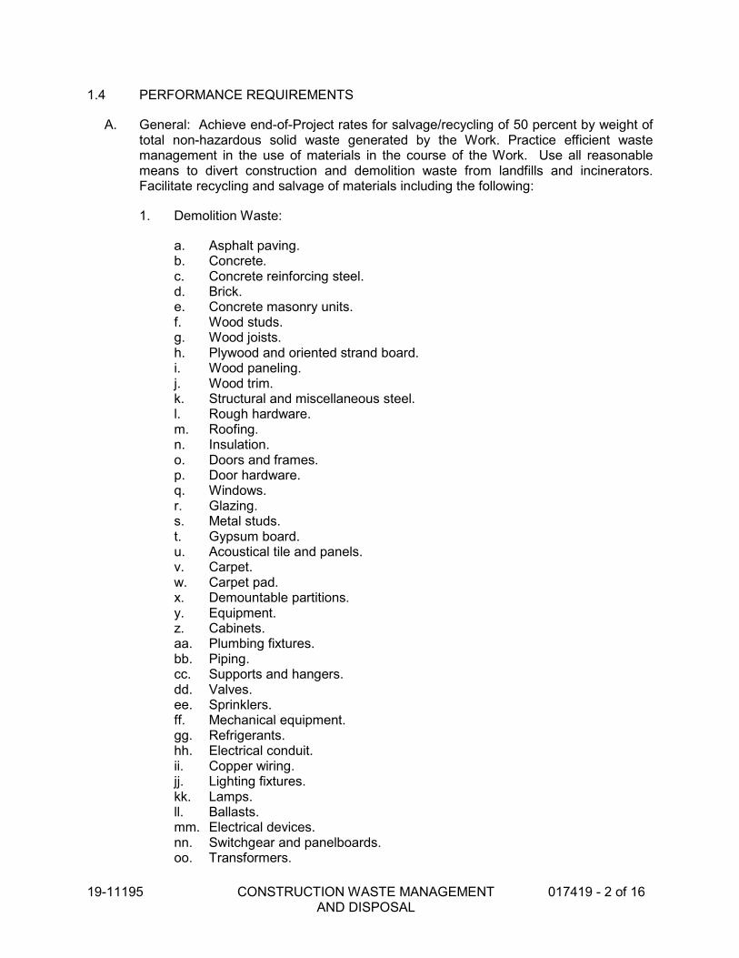
19-11195 CONSTRUCTION WASTE MANAGEMENT AND DISPOSAL
017419 - 2 of 16
1.4 PERFORMANCE REQUIREMENTS
A. General: Achieve end-of-Project rates for salvage/recycling of 50 percent by weight oftotal non-hazardous solid waste generated by the Work. Practice efficient wastemanagement in the use of materials in the course of the Work. Use all reasonablemeans to divert construction and demolition waste from landfills and incinerators.Facilitate recycling and salvage of materials including the following:
1. Demolition Waste:
a. Asphalt paving.b. Concrete.c. Concrete reinforcing steel.d. Brick.e. Concrete masonry units.f. Wood studs.g. Wood joists.h. Plywood and oriented strand board.i. Wood paneling.j. Wood trim.k. Structural and miscellaneous steel.l. Rough hardware.m. Roofing.n. Insulation.o. Doors and frames.p. Door hardware.q. Windows.r. Glazing.s. Metal studs.t. Gypsum board.u. Acoustical tile and panels.v. Carpet.w. Carpet pad.x. Demountable partitions.y. Equipment.z. Cabinets.aa. Plumbing fixtures. bb. Piping. cc. Supports and hangers.dd. Valves.ee. Sprinklers. ff. Mechanical equipment. gg. Refrigerants. hh. Electrical conduit. ii. Copper wiring.jj. Lighting fixtures. kk. Lamps. ll. Ballasts.mm. Electrical devices.nn. Switchgear and panelboards. oo. Transformers.

19-11195
CONSTRUCTION WASTE MANAGEMENT AND DISPOSAL
017419 - 3 of 16
2. Construction Waste:
a. Masonry and CMU. b. Lumber. c. Wood sheet materials. d. Wood trim. e. Metals. f. Roofing. g. Insulation. h. Carpet and pad. i. Gypsum board. j. Piping. k. Electrical conduit. l. Packaging: Regardless of salvage/recycle goal indicated in "General"
Paragraph above, salvage or recycle 100 percent of the following uncontaminated packaging materials:
1) Paper. 2) Cardboard. 3) Boxes. 4) Plastic sheet and film. 5) Polystyrene packaging. 6) Wood crates. 7) Plastic pails.
1.5 ACTION SUBMITTALS
A. Waste Management Plan: Submit plan within 30 days of date established for the Notice to Proceed.
1.6 INFORMATIONAL SUBMITTALS
A. Waste Reduction Progress Reports: Concurrent with each Application for Payment, submit report. Use Form CWM-7 for construction waste and Form CWM-8 for demolition waste (Form(s) included at the end of this Section). Include the following information:
1. Material category. 2. Generation point of waste. 3. Total quantity of waste in tons. 4. Quantity of waste salvaged, both estimated and actual in tons. 5. Quantity of waste recycled, both estimated and actual in tons. 6. Total quantity of waste recovered (salvaged plus recycled) in tons. 7. Total quantity of waste recovered (salvaged plus recycled) as a percentage of
total waste.
B. Waste Reduction Calculations: Before request for Substantial Completion, submit calculated end-of-Project rates for salvage, recycling, and disposal as a percentage of total waste generated by the Work.

19-11195 CONSTRUCTION WASTE MANAGEMENT AND DISPOSAL
017419 - 4 of 16
C. Records of Donations: Indicate receipt and acceptance of salvageable waste donatedto individuals and organizations. Indicate whether organization is tax exempt.
D. Records of Sales: Indicate receipt and acceptance of salvageable waste sold toindividuals and organizations. Indicate whether organization is tax exempt.
E. Recycling and Processing Facility Records: Indicate receipt and acceptance ofrecyclable waste by recycling and processing facilities licensed to accept them.Include manifests, weight tickets, receipts, and invoices.
F. Landfill and Incinerator Disposal Records: Indicate receipt and acceptance of waste bylandfills and incinerator facilities licensed to accept them. Include manifests, weighttickets, receipts, and invoices.
G. Qualification Data: For waste management coordinator and refrigerant recoverytechnician.
H. Statement of Refrigerant Recovery: Signed by refrigerant recovery technicianresponsible for recovering refrigerant, stating that all refrigerant that was present wasrecovered and that recovery was performed according to EPA regulations. Includename and address of technician and date refrigerant was recovered.
1.7 QUALITY ASSURANCE
A. Waste Management Coordinator Qualifications: Experienced firm, with a record ofsuccessful waste management coordination of projects with similar requirements.
B. Refrigerant Recovery Technician Qualifications: Certified by EPA-approved certification program.
C. Regulatory Requirements: Comply with hauling and disposal regulations of authoritieshaving jurisdiction.
D. Waste Management Conference: Conduct conference at Project site to comply withrequirements in Division 01 Section "Project Management and Coordination." Reviewmethods and procedures related to waste management including, but not limited to, thefollowing:
1. Review and discuss waste management plan including responsibilities of wastemanagement coordinator.
2. Review requirements for documenting quantities of each type of waste and itsdisposition.
3. Review and finalize procedures for materials separation and verify availability ofcontainers and bins needed to avoid delays.
4. Review procedures for periodic waste collection and transportation to recyclingand disposal facilities.
5. Review waste management requirements for each trade.

19-11195 CONSTRUCTION WASTE MANAGEMENT AND DISPOSAL
017419 - 5 of 16
1.8 WASTE MANAGEMENT PLAN
A. General: In accordance with California Green Building Standards, Title 24, Part 11,5.408, develop a waste management plan according requirements in this Section.Plan shall consist of waste identification and waste reduction work plan. Distinguishbetween demolition and construction waste. Indicate quantities by weight or volume,but use same units of measure throughout waste management plan.
B. Waste Identification: Indicate anticipated types and quantities of demolition, site-clearing, and construction waste generated by the Work. Use Form CWM-1 forconstruction waste and Form CWM-2 for demolition waste. Include estimatedquantities and assumptions for estimates.
C. Waste Reduction Work Plan: List each type of waste and whether it will be salvaged,recycled, or disposed of in landfill or incinerator. Use Form CWM-3 for constructionwaste and Form CWM-4 for demolition waste. Include points of waste generation, totalquantity of each type of waste, quantity for each means of recovery, and handling andtransportation procedures.
1. Salvaged Materials for Reuse: For materials that will be salvaged and reused inthis Project, describe methods for preparing salvaged materials beforeincorporation into the Work.
2. Salvaged Materials for Sale: For materials that will be sold to individuals andorganizations, include list of their names, addresses, and telephone numbers.
3. Salvaged Materials for Donation: For materials that will be donated to individualsand organizations, include list of their names, addresses, and telephonenumbers.
4. Recycled Materials: Include list of local receivers and processors and type ofrecycled materials each will accept. Include names, addresses, and telephonenumbers.
5. Disposed Materials: Indicate how and where materials will be disposed of.Include name, address, and telephone number of each landfill and incineratorfacility.
6. Handling and Transportation Procedures: Include method that will be used forseparating recyclable waste including sizes of containers, container labeling, anddesignated location where materials separation will be performed.
PART 2 - PRODUCTS (Not Used)
PART 3 - EXECUTION
3.1 PLAN IMPLEMENTATION
A. General: Implement approved waste management plan. Provide handling, containers,storage, signage, transportation, and other items as required to implement wastemanagement plan during the entire duration of the Contract.

19-11195 CONSTRUCTION WASTE MANAGEMENT AND DISPOSAL
017419 - 6 of 16
1. Comply with operation, termination, and removal requirements in Division 01Section "Temporary Facilities and Controls."
B. Waste Management Coordinator: Engage a waste management coordinator to beresponsible for implementing, monitoring, and reporting status of waste managementwork plan.
C. Training: Train workers, subcontractors, and suppliers on proper waste managementprocedures, as appropriate for the Work.
1. Distribute waste management plan to everyone concerned within three days ofsubmittal return.
2. Distribute waste management plan to entities when they first begin work on-site.Review plan procedures and locations established for salvage, recycling, anddisposal.
D. Site Access and Temporary Controls: Conduct waste management operations toensure minimum interference with roads, streets, walks, walkways, and other adjacentoccupied and used facilities.
1. Designate and label specific areas on Project site necessary for separatingmaterials that are to be salvaged, recycled, reused, donated, and sold.
2. Comply with Division 01 Section "Temporary Facilities and Controls" forcontrolling dust and dirt, environmental protection, and noise control.
3.2 SALVAGING DEMOLITION WASTE
A. Salvaged Items for Reuse in the Work: Salvage items for reuse and handle as follows:
1. Clean salvaged items.2. Pack or crate items after cleaning. Identify contents of containers with label
indicating elements, date of removal, quantity, and location where removed.3. Store items in a secure area until installation.4. Protect items from damage during transport and storage.5. Install salvaged items to comply with installation requirements for new materials
and equipment. Provide connections, supports, and miscellaneous materialsnecessary to make items functional for use indicated.
B. Salvaged Items for Sale and/or Donation: Not permitted on Project site.
C. Salvaged Items for Owner's Use: Salvage items for Owner's use and handle asfollows:
1. Clean salvaged items.2. Pack or crate items after cleaning. Identify contents of containers with label
indicating elements, date of removal, quantity, and location where removed.3. Store items in a secure area until delivery to Owner.4. Transport items to Owner's storage area designated by Owner.5. Protect items from damage during transport and storage.

19-11195 CONSTRUCTION WASTE MANAGEMENT AND DISPOSAL
017419 - 7 of 16
D. Doors and Hardware: Brace open end of door frames. Except for removing doorclosers, leave door hardware attached to doors.
E. Equipment: Drain tanks, piping, and fixtures. Seal openings with caps or plugs.Protect equipment from exposure to weather.
F. Plumbing Fixtures: Separate by type and size.
G. Lighting Fixtures: Separate lamps by type and protect from breakage.
H. Electrical Devices: Separate switches, receptacles, switchgear, transformers, meters,panelboards, circuit breakers, and other devices by type.
3.3 RECYCLING DEMOLITION AND CONSTRUCTION WASTE, GENERAL
A. General: Recycle paper and beverage containers used by on-site workers.
B. Recycling Receivers and Processors: Refer to local county websites for the county inwhich the Project is located for listings of available recycling receivers and processors,and materials accepted.
C. Recycling Incentives: Revenues, savings, rebates, tax credits, and other incentivesreceived for recycling waste materials shall accrue to Contractor.
D. Preparation of Waste: Prepare and maintain recyclable waste materials according torecycling or reuse facility requirements. Maintain materials free of dirt, adhesives,solvents, petroleum contamination, and other substances deleterious to the recyclingprocess.
E. Procedures: Separate recyclable waste from other waste materials, trash, and debris.Separate recyclable waste by type at Project site to the maximum extent practicalaccording to approved construction waste management plan.
1. Provide appropriately marked containers or bins for controlling recyclable wasteuntil removed from Project site. Include list of acceptable and unacceptablematerials at each container and bin.
a. Inspect containers and bins for contamination and remove contaminatedmaterials if found.
2. Stockpile processed materials on-site without intermixing with other materials.Place, grade, and shape stockpiles to drain surface water. Cover to preventwindblown dust.
3. Stockpile materials away from construction area. Do not store within drip line ofremaining trees.
4. Store components off the ground and protect from the weather.5. Remove recyclable waste from Owner's property and transport to recycling
receiver or processor.

19-11195 CONSTRUCTION WASTE MANAGEMENT AND DISPOSAL
017419 - 8 of 16
3.4 RECYCLING DEMOLITION WASTE
A. Asphalt Paving: Break up and transport paving to asphalt-recycling facility.
B. Concrete: Remove reinforcement and other metals from concrete and sort with othermetals.
C. Masonry: Remove metal reinforcement, anchors, and ties from masonry and sort withother metals.
1. Clean and stack undamaged, whole masonry units on wood pallets.
D. Wood Materials: Sort and stack members according to size, type, and length.Separate lumber, engineered wood products, panel products, and treated woodmaterials.
E. Metals: Separate metals by type.
1. Structural Steel: Stack members according to size, type of member, and length.2. Remove and dispose of bolts, nuts, washers, and other rough hardware.
F. Asphalt Shingle Roofing: Separate organic and glass-fiber asphalt shingles and felts.Remove and dispose of nails, staples, and accessories.
G. Gypsum Board: Stack large clean pieces on wood pallets or in container and store in adry location. Remove edge trim and sort with other metals. Remove and dispose offasteners.
H. Acoustical Ceiling Panels and Tile: Stack large clean pieces on wood pallets and storein a dry location.
I. Metal Suspension System: Separate metal members including trim, and other metalsfrom acoustical panels and tile and sort with other metals.
J. Carpet and Pad: Roll large pieces tightly after removing debris, trash, adhesive, andtack strips.
1. Store clean, dry carpet and pad in a closed container or trailer provided byCarpet Reclamation Agency or carpet recycler.
K. Carpet Tile: Remove debris, trash, and adhesive.
1. Stack tile on pallet and store clean, dry carpet in a closed container or trailerprovided by Carpet Reclamation Agency or carpet recycler.
L. Metal Piping: Reduce piping to straight lengths and store by type and size. Separatesupports, hangers, valves, sprinklers, and other components by type and size.
M. Metal Conduit: Reduce conduit to straight lengths and store by type and size.

19-11195 CONSTRUCTION WASTE MANAGEMENT AND DISPOSAL
017419 - 9 of 16
3.5 RECYCLING CONSTRUCTION WASTE
A. Packaging:
1. Cardboard and Boxes: Break down packaging into flat sheets. Bundle and storein a dry location.
2. Polystyrene Packaging: Separate and bag materials.3. Pallets: As much as possible, require deliveries using pallets to remove pallets
from Project site. For pallets that remain on-site, break down pallets intocomponent wood pieces and comply with requirements for recycling wood.
4. Crates: Break down crates into component wood pieces and comply withrequirements for recycling wood.
B. Wood Materials:
1. Clean Cut-Offs of Lumber: Grind or chip into small pieces.2. Clean Sawdust: Bag sawdust that does not contain painted or treated wood.
a. Comply with requirements in Division 32 Sections as applicable to plantingfor use of clean sawdust as organic mulch.
C. Gypsum Board: Stack large clean pieces on wood pallets or in container and store in adry location.
3.6 DISPOSAL OF WASTE
A. General: Except for items or materials to be salvaged, recycled, or otherwise reused,remove waste materials from Project site and legally dispose of them in a landfill orincinerator acceptable to authorities having jurisdiction.
1. Except as otherwise specified, do not allow waste materials that are to bedisposed of accumulate on-site.
2. Remove and transport debris in a manner that will prevent spillage on adjacentsurfaces and areas.
B. Burning: Do not burn waste materials.
C. Disposal: Remove waste materials from Owner's property and legally dispose of them.
3.7 ATTACHMENTS
A. Form CWM-1 for construction waste identification.
B. Form CWM-2 for demolition waste identification.
C. Form CWM-3 for construction waste reduction work plan.
D. Form CWM-4 for demolition waste reduction work plan.
E. Form CWM-7 for construction waste

19-11195 CONSTRUCTION WASTE MANAGEMENT AND DISPOSAL
017419 - 10 of 16
F. Form CWM-8 for demolition waste.
END OF SECTION
(Forms CWM-1 through CWM-8 on the following pages)

19-1
1195
C
ON
ST
RU
CT
ION
WA
ST
E M
AN
AG
EM
EN
T
AN
D D
ISP
OS
AL
017419 - 1
1 o
f 16
FORM CWM-1 CONSTRUCTION WASTE IDENTIFICATION
REMARKS AND
ASSUMPTIONS
EST. WEIGHT
(TONS)
EST. VOL.
(CUBIC YD.)
TOTAL EST.
QUAN. OF
WASTE (C=A x B)
EST. WASTE -
PERCENT
(B)
EST. QUAN. OF
MATL’S REC’D.
(A)
GENERATION
POINT
MATERIAL CATEGORY
Packaging: Cardboard
Packaging: Boxes
Packaging: Plastic sheet/film
Packaging: Polystyrene
Packaging: Pallets or skids
Packaging: Crates
Packaging: Paint cans
Packaging: Plastic pails
Site Clearing Waste
Masonry or CMU
Lumber: Cut ofs
Lumber: Warped pieces
Plywood or OSB (scraps)
Wood Forms
Wood Waste Chutes
Wood Trim (Cut offs)
Metals
Insulation
Roofing
Joint Sealant Tubes
Gypsum Board (scraps)
Carpet and Pad (scraps)
Piping
Electrical Conduit
Other

19-1
1195
CO
NS
TR
UC
TIO
N W
AS
TE
MA
NA
GE
ME
NT
A
ND
DIS
PO
SA
L
017419 - 1
2 o
f 16
FORM CWM-2: DEMOLITION WASTE IDENTIFICATION
REMARKS AND ASSUMPTIONS EST. WEIGHT (TONS) EST. VOL. (CY) EST. QUAN. MATERIAL DESCRIPTION
AC Paving
Concrete
Brick
CMU
Lumber
Plywood and OSB
Wood Paneling
Wood Trim
Miscellaneous Metals
Structural Steel
Rough Hardware
Windows
Glazing
Acoustical Tile
Carpet
Carpet Pad
Demountable Partitions
Equipment
Cabinets
Plumbing Fixtures
Piping
Piping Supports and Hangers
Valves
Sprinklers
Mechanical Equipment
Electrical Conduit
Copper Wiring
Light Fixtures
Lamps
Lighting Ballasts
Electrical Devisces
Switchgear and Panelboards
Transformers
Other

19-1
1195
CO
NS
TR
UC
TIO
N W
AS
TE
MA
NA
GE
ME
NT
A
ND
DIS
PO
SA
L
017419 - 1
3 o
f 16
FORM CWM-3: CONSTRUCTION WASTE REDUCTION WORK PLAN
HANDLING AND
TRANSP.
PROCEDURES
DISPOSAL METHOD AND QUANTITY
EST. AMOUNT
DISPOSED TO
LANDFILL (TONS)
EST. AMOUNT
RECYCLED
(TONS)
EST. AMT.
SALVAGED (TONS)
TOTAL EST. QUAN.
OF WASTE
(TONS)
GENERATION POINT MATERIAL CATEGORY
Packaging: Cardboard
Packaging: Boxes
Packaging: Plastic sheet/film
Packaging: Polystyrene
Packaging: Pallets or skids
Packaging: Crates
Packaging: Paint cans
Packaging: Plastic pails
Site Clearing Waste
Masonry or CMU
Lumber: Cut ofs
Lumber: Warped pieces
Plywood or OSB (scraps)
Wood Forms
Wood Waste Chutes
Wood Trim (Cut offs)
Metals
Insulation
Roofing
Joint Sealant Tubes
Gypsum Board (scraps)
Carpet and Pad (scraps)
Piping
Electrical Conduit
Other

19-1
1195
CO
NS
TR
UC
TIO
N W
AS
TE
MA
NA
GE
ME
NT
A
ND
DIS
PO
SA
L
017419 - 1
4 o
f 16
FORM CWM-4: DEMOLITION WASTE REDUCTION WORK PLAN
HANDLING AND
TRANSP.
PROCEDURES
DISPOSAL METHOD AND QUANTITY
EST. AMOUNT
DISPOSED TO
LANDFILL (TONS)
EST. AMOUNT
RECYCLED
(TONS)
EST. AMT.
SALVAGED (TONS)
TOTAL EST. QUAN.
OF WASTE
(TONS)
GENERATION POINT MATERIAL CATEGORY
AC Paving
Concrete
Brick
CMU
Lumber
Plywood and OSB
Wood Paneling
Wood Trim
Miscellaneous Metals
Structural Steel
Rough Hardware
Windows
Glazing
Acoustical Tile
Carpet
Carpet Pad
Demountable Partitions
Equipment
Cabinets
Plumbing Fixtures
Piping
Piping Supports and Hangers
Valves
Sprinklers
Mechanical Equipment
Electrical Conduit
Copper Wiring
Light Fixtures
Lamps
Lighting Ballasts
Electrical Devisces
Switchgear and Panelboards
Transformers
Other

19-1
1195
C
ON
ST
RU
CT
ION
WA
ST
E M
AN
AG
EM
EN
T
AN
D D
ISP
OS
AL
017419 - 1
5 o
f 16
FORM CWM-7 CONSTRUCTION WASTE REDUCTION PROGRESS REPORT
TOT. QUAN. OF WASTE
RECOVERED,
(PERCENT)
(D/A x 100)
TOT. QUAN. OF WASTE
RECOVERED,
TONS
(D=B+C)
QUAN. OF WASTE RECYCLED
ACTUAL
TONS
(C)
EST. TONS
QUAN. OF WASTE SALVAGED
ACTUAL
TONS
(B)
EST. TONS
TOT. QUAN. OF WASTE,
TONS
(A)
GENERATION POINT
MATERIAL CATEGORY
Packaging: Cardboard
Packaging: Boxes
Packaging: Plastic sheet/film
Packaging: Polystyrene
Packaging: Pallets or skids
Packaging: Crates
Packaging: Paint cans
Packaging: Plastic pails
Site Clearing Waste
Masonry or CMU
Lumber: Cut ofs
Lumber: Warped pieces
Plywood or OSB (scraps)
Wood Forms
Wood Waste Chutes
Wood Trim (Cut offs)
Metals
Insulation
Roofing
Joint Sealant Tubes
Gypsum Board (scraps)
Carpet and Pad (scraps)
Piping
Electrical Conduit
Other

19-1
1195
C
ON
ST
RU
CT
ION
WA
ST
E M
AN
AG
EM
EN
T
AN
D D
ISP
OS
AL
017419 - 1
6 o
f 16
FORM CWM-8: DEMOLITION WASTE REDUCTION PROGRESS REPORT
TOT. QUAN.
OF WASTE RECOVERED
(PERCENT)
(D/A x 100)
TOT. QUAN.
OF WASTE RECOVERED,
TONS
(D=B+C)
QUAN. OF WASTE RECYCLED
ACTUAL
TONS
(C)
EST. TONS
QUAN. OF WASTE SALVAGED
ACTUAL
TONS
(B)
EST. TONS
TOT. QUAN.
OF WASTE, TONS
(A)
GENERATION
POINT
MATERIAL CATEGORY
AC Paving
Concrete
Brick
CMU
Lumber
Plywood and OSB
Wood Paneling
Wood Trim
Miscellaneous Metals
Structural Steel
Rough Hardware
Windows
Glazing
Acoustical Tile
Carpet
Carpet Pad
Demountable Partitions
Equipment
Cabinets
Plumbing Fixtures
Piping
Piping Supports and Hangers
Valves
Sprinklers
Mechanical Equipment
Electrical Conduit
Copper Wiring
Light Fixtures
Lamps
Lighting Ballasts
Electrical Devisces
Switchgear and Panelboards
Transformers
Other

19-11195 CLOSEOUT PROCEDURES 017700 - 1 of 5
SECTION 017700 CLOSEOUT PROCEDURES
PART 1 - GENERAL
1.1 RELATED DOCUMENTS
A. Drawings and general provisions of the Contract, including General and SupplementaryConditions and other Division 01 Specification Sections, apply to this Section.
1.2 SUMMARY
A. Section includes administrative and procedural requirements for contract closeout,including, but not limited to, the following:
1. Closeout procedures at completion.2. Final cleaning.3. Repair of the Work.
B. Related Requirements:
1. Division 01 Section "Project Record Drawings" for submitting record Drawings.2. Division 01 Section "Warranties" for submitting final warranty information.3. Divisions 02 through 33 Sections for specific closeout and special cleaning
requirements for the Work in those Sections.
1.3 SUBMITTALS
A. Submittals Prior to Substantial Completion: Submit the following a minimum of 10 daysprior to requesting inspection for determining date of Substantial Completion. List itemsbelow that are incomplete at time of request.
1. Certificates of Release: Obtain and submit releases from authorities havingjurisdiction permitting Owner unrestricted use of the Work and access to servicesand utilities. Include occupancy permits, operating certificates, and similarreleases.
2. Submit closeout submittals specified in other Division 01 Sections, includingproject record drawings, operation and maintenance manuals, warranties, andsimilar final record information.
3. Submit closeout submittals specified in individual Divisions 02 through 33Sections, including specific warranties, workmanship bonds, maintenance serviceagreements, final certifications, and similar documents.
4. Submit maintenance material submittals specified in individualDivisions 02 through 33 Sections, including tools, spare parts, extra materials, andsimilar items, and deliver to location designated by Architect. Label withmanufacturer's name and model number where applicable.
5. Submit test/adjust/balance records.

19-11195 CLOSEOUT PROCEDURES 017700 - 2 of 5
6. Submit changeover information related to Owner's occupancy, use, operation, andmaintenance.
1.4 CLOSEOUT PROCEDURES
A. Procedures Prior to Completion: Complete the following a minimum of 10 days prior torequesting inspection for determining date of Completion. List items below that areincomplete at time of request.
1. Advise Owner of pending insurance changeover requirements.2. Make final changeover of permanent locks and deliver keys to Owner. Advise
Owner's personnel of changeover in security provisions.3. Complete startup and testing of systems and equipment.4. Perform preventive maintenance on equipment used prior to Substantial
Completion.5. Instruct Owner's personnel in operation, adjustment, and maintenance of products,
equipment, and systems. Submit demonstration and training video recordingsspecified in Division 01 Section "Demonstration and Training."
6. Advise Owner of changeover in utilities.7. Terminate and remove temporary facilities from Project site, along with mockups,
construction tools, and similar elements.8. Complete final cleaning requirements, including touchup painting.9. Touch up and otherwise repair and restore marred exposed finishes to eliminate
visual defects.
B. Inspection: Submit a written request for inspection for Completion a minimum of 10 daysprior to date the work will be completed and ready for inspection. On receipt of request,Architect will either proceed with inspection or notify Contractor of unfulfilledrequirements. Architect will prepare the Certificate of Substantial Completion afterinspection or will notify Contractor of items, either on Contractor's list or additional itemsidentified by Architect, that must be completed or corrected before certificate will beissued.
1. Architect’s Punch List: During inspection, Architect will prepare a list of itemsneeding completion or correction (punch list), a copy of the punch list will bedistributed to the contractor and Owner.
2. Reinspection: Request reinspection when the Work identified in previousinspection as incomplete is completed or corrected.
3. Results of completed inspection will form the basis of requirements for finalcompletion.
C. Contractor’s Cost for Reinspection: Architect will perform one inspection and onereinspection at no additional cost to the Contractor. The expense for the Architect’s timefor additional inspections will be paid by the Owner with the amount being deducted fromthe Contract Sum. The expense will be based on an hourly rate in accordance with theArchitect’s standard hourly rate schedule in effect at the time the work is performed witha minimum of $400.00 dollars for each additional reinspection.

19-11195 CLOSEOUT PROCEDURES 017700 - 3 of 5
PART 2 - PRODUCTS
2.1 MATERIALS
A. Cleaning Agents: Use cleaning materials and agents recommended by manufacturer or fabricator of the surface to be cleaned. Do not use cleaning agents that are potentially hazardous to health or property or that might damage finished surfaces.
1. Use cleaning products that comply with Green Seal's GS-37, or if GS-37 is not applicable, use products that comply with the California Code of Regulations maximum allowable VOC levels.
PART 3 - EXECUTION
3.1 FINAL CLEANING
A. General: Perform final cleaning. Conduct cleaning and waste-removal operations to comply with local laws and ordinances and Federal and local environmental and antipollution regulations.
B. Cleaning: Employ experienced workers or professional cleaners for final cleaning. Clean each surface or unit to condition expected in an average commercial building cleaning and maintenance program. Comply with manufacturer's written instructions.
1. Complete the following cleaning operations before requesting inspection for Completion for entire Project or for a designated portion of Project:
a. Clean Project site, yard, and grounds, in areas disturbed by construction activities, including landscape development areas, of rubbish, waste material, litter, and other foreign substances.
b. Sweep paved areas broom clean. Remove petrochemical spills, stains, and other foreign deposits.
c. Rake grounds that are neither planted nor paved to a smooth, even-textured surface.
d. Remove tools, construction equipment, machinery, and surplus material from Project site.
e. Clean exposed exterior and interior hard-surfaced finishes to a dirt-free condition, free of stains, films, and similar foreign substances. Avoid disturbing natural weathering of exterior surfaces. Restore reflective surfaces to their original condition.
f. Remove debris and surface dust from limited access spaces, including roofs, plenums, shafts, trenches, equipment vaults, manholes, attics, and similar spaces.
g. Sweep concrete floors broom clean in unoccupied spaces. h. Vacuum carpet and similar soft surfaces, removing debris and excess nap;
clean according to manufacturer's recommendations if visible soil or stains remain.

19-11195 CLOSEOUT PROCEDURES 017700 - 4 of 5
i. Clean transparent materials, including mirrors and glass in doors andwindows. Remove glazing compounds and other noticeable, vision-obscuring materials. Polish mirrors and glass, taking care not to scratchsurfaces.
j. Remove labels that are not permanent.k. Wipe surfaces of mechanical, electrical, and similar equipment. Remove
excess lubrication, paint and mortar droppings, and other foreignsubstances.
l. Clean plumbing fixtures to a sanitary condition, free of stains, including stainsresulting from water exposure.
m. Replace disposable air filters and clean permanent air filters. Clean exposedsurfaces of diffusers, registers, and grills.
n. Clean ducts, blowers, and coils if units were operated without filters duringconstruction or that display contamination with particulate matter oninspection.
o. Clean light fixtures, lamps, globes, and reflectors to function with fullefficiency.
p. Leave Project clean and ready for occupancy.
C. Construction Waste Disposal: Comply with waste disposal requirements in Division 01Section "Construction Waste Management and Disposal."
3.2 REPAIR OF THE WORK
A. Complete repair and restoration operations before requesting inspection fordetermination of Substantial Completion.
1. Comply with requirements of Division 02 through 33 Sections as applicable to theWork to be restored and/or repaired.
B. Repair or remove and replace defective construction. Repairing includes replacingdefective parts, refinishing damaged surfaces, touching up with matching materials, andproperly adjusting operating equipment. Where damaged or worn items cannot berepaired or restored, provide replacements. Remove and replace operating componentsthat cannot be repaired. Restore damaged construction and permanent facilities usedduring construction to specified condition.
1. Remove and replace chipped, scratched, and broken glass, reflective surfaces,and other damaged transparent materials.
2. Touch up and otherwise repair and restore marred or exposed finishes andsurfaces. Replace finishes and surfaces that that already show evidence of repairor restoration.
a. Do not paint over "UL" and other required labels and identification, includingmechanical and electrical nameplates. Remove paint applied to requiredlabels and identification.
3. Replace parts subject to operating conditions during construction that may impedeoperation or reduce longevity.

19-11195 CLOSEOUT PROCEDURES 017700 - 5 of 5
4. Replace burned-out bulbs, bulbs noticeably dimmed by hours of use, and defectiveand noisy starters in fluorescent and mercury vapor fixtures to comply withrequirements for new fixtures.
END OF SECTION


19-11195 OPERATION AND MAINTENANCE DATA 017823 – 1 of 8
SECTION 017823 OPERATION AND MAINTENANCE DATA
PART 1 - GENERAL
1.1 RELATED DOCUMENTS
A. Drawings and general provisions of the Contract, including General and SupplementaryConditions and other Division 01 Specification Sections, apply to this Section.
1.2 SUMMARY
A. Section includes administrative and procedural requirements for preparing operation andmaintenance manuals, including the following:
1. Operation and maintenance documentation directory.2. Emergency manuals.3. Operation manuals for systems, subsystems, and equipment.4. Product maintenance manuals.5. Systems and equipment maintenance manuals.
B. Related Sections:
1. Division 01 Section "Submittal Procedures" for submitting copies of submittals foroperation and maintenance manuals.
2. Divisions 02 through 33 Sections for specific operation and maintenance manualrequirements for the Work in those Sections.
1.3 DEFINITIONS
A. System: An organized collection of parts, equipment, or subsystems united by regularinteraction.
B. Subsystem: A portion of a system with characteristics similar to a system.1.4 SUBMITTALS
A. Operation and Maintenance Manuals: Operations and maintenance manual content isspecified in individual specification sections to be reviewed at the time of Sectionsubmittals. Submit reviewed manual content formatted and organized as required bythis Section. Where applicable, clarify and update reviewed manual content tocorrespond to modifications and field conditions.
1. Format: Submit operations and maintenance manuals in the following format:
a. 3 paper copies. Include a complete operation and maintenance directory.Enclose title pages and directories in clear plastic sleeves. Architect willreturn 2 copies.

19-11195 OPERATION AND MAINTENANCE DATA 017823 – 2 of 8
2. Initial Manual Submittal: Submit draft copy of each manual at least 30 days beforecommencing demonstration and training. Architect will comment on whethergeneral scope and content of manual are acceptable.
3. Final Manual Submittal: Submit each manual in final form prior to requestinginspection for Substantial Completion and at least 15 days before commencingdemonstration and training. Architect will return copy with comments.
a. Correct or modify each manual to comply with Architect's comments. Submitcopies of each corrected manual within 15 days of receipt of Architect'scomments and prior to commencing demonstration and training.
PART 2 - PRODUCTS
2.1 OPERATION AND MAINTENANCE DOCUMENTATION DIRECTORY
A. Organization: Include a section in the directory for each of the following:
1. List of documents.2. List of systems.3. List of equipment.4. Table of contents.
B. List of Systems and Subsystems: List systems alphabetically. Include references tooperation and maintenance manuals that contain information about each system.
C. List of Equipment: List equipment for each system, organized alphabetically by system.For pieces of equipment not part of system, list alphabetically in separate list.
D. Tables of Contents: Include a table of contents for each emergency, operation, andmaintenance manual.
E. Identification: In the documentation directory and in each operation and maintenancemanual, identify each system, subsystem, and piece of equipment with same designationused in the Contract Documents. If no designation exists, assign a designationaccording to ASHRAE Guideline 4, "Preparation of Operating and MaintenanceDocumentation for Building Systems."
2.2 REQUIREMENTS FOR EMERGENCY, OPERATION, AND MAINTENANCE MANUALS
A. Organization: Unless otherwise indicated, organize each manual into a separate sectionfor each system and subsystem, and a separate section for each piece of equipment notpart of a system. Each manual shall contain the following materials, in the order listed:
1. Title page.2. Table of contents.3. Manual contents.
B. Title Page: Include the following information:

19-11195 OPERATION AND MAINTENANCE DATA 017823 – 3 of 8
1. Subject matter included in manual.2. Name and address of Project.3. Name and address of Owner.4. Date of submittal.5. Name and contact information for Contractor.6. Name and contact information for Installer and/or Subcontractor.7. Name and contact information for Architect.8. Names and contact information for major consultants to the Architect that designed
the systems contained in the manuals.9. Cross-reference to related systems in other operation and maintenance manuals.
C. Table of Contents: List each product included in manual, identified by product name,indexed to the content of the volume, and cross-referenced to Specification Sectionnumber in Project Manual.
1. If operation or maintenance documentation requires more than one volume toaccommodate data, include comprehensive table of contents for all volumes ineach volume of the set.
D. Manual Contents: Organize into sets of manageable size. Arrange contentsalphabetically by system, subsystem, and equipment. If possible, assemble instructionsfor subsystems, equipment, and components of one system into a single binder.
E. Manuals, Paper Copy: Submit manuals in the form of hard copy, bound and labeledvolumes.
1. Binders: Heavy-duty, three-ring, vinyl-covered, loose-leaf binders, in thicknessnecessary to accommodate contents, sized to hold 8-1/2-by-11-inch paper; withclear plastic sleeve on spine to hold label describing contents and with pocketsinside covers to hold folded oversize sheets.
a. If two or more binders are necessary to accommodate data of a system,organize data in each binder into groupings by subsystem and relatedcomponents. Cross-reference other binders if necessary to provideessential information for proper operation or maintenance of equipment orsystem.
b. Identify each binder on front and spine, with printed title "OPERATION ANDMAINTENANCE MANUAL," Project title or name, and subject matter ofcontents, and indicate Specification Section number on bottom of spine.Indicate volume number for multiple-volume sets.
2. Dividers: Heavy-paper dividers with plastic-covered tabs for each section of themanual. Mark each tab to indicate contents. Include typed list of products andmajor components of equipment included in the section on each divider, cross-referenced to Specification Section number and title of Project Manual.
3. Protective Plastic Sleeves: Transparent plastic sleeves designed to enclosediagnostic software storage media for computerized electronic equipment.
4. Supplementary Text: Prepared on 8-1/2-by-11-inch white bond paper.5. Drawings: Attach reinforced, punched binder tabs on drawings and bind with text.
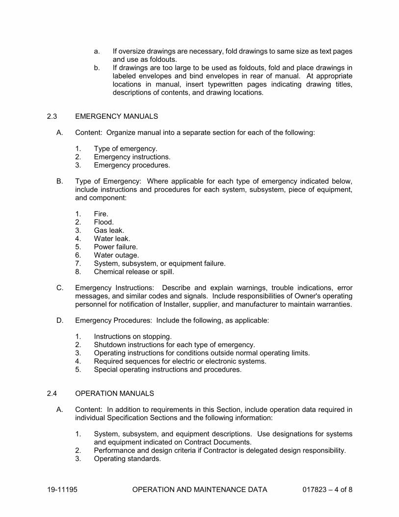
19-11195 OPERATION AND MAINTENANCE DATA 017823 – 4 of 8
a. If oversize drawings are necessary, fold drawings to same size as text pagesand use as foldouts.
b. If drawings are too large to be used as foldouts, fold and place drawings inlabeled envelopes and bind envelopes in rear of manual. At appropriatelocations in manual, insert typewritten pages indicating drawing titles,descriptions of contents, and drawing locations.
2.3 EMERGENCY MANUALS
A. Content: Organize manual into a separate section for each of the following:
1. Type of emergency.2. Emergency instructions.3. Emergency procedures.
B. Type of Emergency: Where applicable for each type of emergency indicated below,include instructions and procedures for each system, subsystem, piece of equipment,and component:
1. Fire.2. Flood.3. Gas leak.4. Water leak.5. Power failure.6. Water outage.7. System, subsystem, or equipment failure.8. Chemical release or spill.
C. Emergency Instructions: Describe and explain warnings, trouble indications, errormessages, and similar codes and signals. Include responsibilities of Owner's operatingpersonnel for notification of Installer, supplier, and manufacturer to maintain warranties.
D. Emergency Procedures: Include the following, as applicable:
1. Instructions on stopping.2. Shutdown instructions for each type of emergency.3. Operating instructions for conditions outside normal operating limits.4. Required sequences for electric or electronic systems.5. Special operating instructions and procedures.
2.4 OPERATION MANUALS
A. Content: In addition to requirements in this Section, include operation data required inindividual Specification Sections and the following information:
1. System, subsystem, and equipment descriptions. Use designations for systemsand equipment indicated on Contract Documents.
2. Performance and design criteria if Contractor is delegated design responsibility.3. Operating standards.

19-11195 OPERATION AND MAINTENANCE DATA 017823 – 5 of 8
4. Operating procedures. 5. Operating logs. 6. Wiring diagrams. 7. Control diagrams. 8. Piped system diagrams. 9. Precautions against improper use. 10. License requirements including inspection and renewal dates.
B. Descriptions: Include the following:
1. Product name and model number. Use designations for products indicated on Contract Documents.
2. Manufacturer's name. 3. Equipment identification with serial number of each component. 4. Equipment function. 5. Operating characteristics. 6. Limiting conditions. 7. Performance curves. 8. Engineering data and tests. 9. Complete nomenclature and number of replacement parts.
C. Operating Procedures: Include the following, as applicable:
1. Startup procedures. 2. Equipment or system break-in procedures. 3. Routine and normal operating instructions. 4. Regulation and control procedures. 5. Instructions on stopping. 6. Normal shutdown instructions. 7. Seasonal and weekend operating instructions. 8. Required sequences for electric or electronic systems. 9. Special operating instructions and procedures.
D. Systems and Equipment Controls: Describe the sequence of operation, and diagram controls as installed.
E. Piped Systems: Diagram piping as installed, and identify color-coding where required for identification.
2.5 PRODUCT MAINTENANCE MANUALS
A. Content: Organize manual into a separate section for each product, material, and finish. Include source information, product information, maintenance procedures, repair materials and sources, and warranties and bonds, as described below.
B. Source Information: List each product included in manual, identified by product name and arranged to match manual's table of contents. For each product, list name, address, and telephone number of Installer or supplier and maintenance service agent, and cross-reference Specification Section number and title in Project Manual and drawing or schedule designation or identifier where applicable.

19-11195 OPERATION AND MAINTENANCE DATA 017823 – 6 of 8
C. Product Information: Include the following, as applicable:
1. Product name and model number. 2. Manufacturer's name. 3. Color, pattern, and texture. 4. Material and chemical composition. 5. Reordering information for specially manufactured products.
D. Maintenance Procedures: Include manufacturer's written recommendations and the following:
1. Inspection procedures. 2. Types of cleaning agents to be used and methods of cleaning. 3. List of cleaning agents and methods of cleaning detrimental to product. 4. Schedule for routine cleaning and maintenance. 5. Repair instructions.
E. Repair Materials and Sources: Include lists of materials and local sources of materials and related services.
F. Warranties and Bonds: Include copies of warranties and bonds and lists of circumstances and conditions that would affect validity of warranties or bonds.
1. Include procedures to follow and required notifications for warranty claims.
2.6 SYSTEMS AND EQUIPMENT MAINTENANCE MANUALS
A. Content: For each system, subsystem, and piece of equipment not part of a system, include source information, manufacturers' maintenance documentation, maintenance procedures, maintenance and service schedules, spare parts list and source information, maintenance service contracts, and warranty and bond information, as described below.
B. Source Information: List each system, subsystem, and piece of equipment included in manual, identified by product name and arranged to match manual's table of contents. For each product, list name, address, and telephone number of Installer or supplier and maintenance service agent, and cross-reference Specification Section number and title in Project Manual and drawing or schedule designation or identifier where applicable.
C. Manufacturers' Maintenance Documentation: Manufacturers' maintenance documentation including the following information for each component part or piece of equipment:
1. Standard maintenance instructions and bulletins. 2. Drawings, diagrams, and instructions required for maintenance, including
disassembly and component removal, replacement, and assembly. 3. Identification and nomenclature of parts and components. 4. List of items recommended to be stocked as spare parts.
D. Maintenance Procedures: Include the following information and items that detail essential maintenance procedures:

19-11195 OPERATION AND MAINTENANCE DATA 017823 – 7 of 8
1. Test and inspection instructions.2. Troubleshooting guide.3. Precautions against improper maintenance.4. Disassembly; component removal, repair, and replacement; and reassembly
instructions.5. Aligning, adjusting, and checking instructions.6. Demonstration and training video recording, if available.
E. Maintenance and Service Schedules: Include service and lubrication requirements, listof required lubricants for equipment, and separate schedules for preventive and routinemaintenance and service with standard time allotment.
1. Scheduled Maintenance and Service: Tabulate actions for daily, weekly, monthly,quarterly, semiannual, and annual frequencies.
2. Maintenance and Service Record: Include manufacturers' forms for recordingmaintenance.
F. Spare Parts List and Source Information: Include lists of replacement and repair parts,with parts identified and cross-referenced to manufacturers' maintenance documentationand local sources of maintenance materials and related services.
G. Maintenance Service Contracts: Include copies of maintenance agreements with nameand telephone number of service agent.
H. Warranties and Bonds: Include copies of warranties and bonds and lists of circumstances and conditions that would affect validity of warranties or bonds.
1. Include procedures to follow and required notifications for warranty claims.
PART 3 - EXECUTION
3.1 MANUAL PREPARATION
A. Operation and Maintenance Documentation Directory: Prepare a separate manual thatprovides an organized reference to emergency, operation, and maintenance manuals.
B. Emergency Manual: Assemble a complete set of emergency information indicatingprocedures for use by emergency personnel and by Owner's operating personnel fortypes of emergencies indicated.
C. Product Maintenance Manual: Assemble a complete set of maintenance data indicatingcare and maintenance of each product, material, and finish incorporated into the Work.
D. Operation and Maintenance Manuals: Assemble a complete set of operation andmaintenance data indicating operation and maintenance of each system, subsystem,and piece of equipment not part of a system.

19-11195 OPERATION AND MAINTENANCE DATA 017823 – 8 of 8
1. Engage a factory-authorized service representative to assemble and prepareinformation for each system, subsystem, and piece of equipment not part of asystem.
2. Prepare a separate manual for each system and subsystem, in the form of aninstructional manual for use by Owner's operating personnel.
E. Manufacturers' Data: Where manuals contain manufacturers' standard printed data,include only sheets pertinent to product or component installed. Mark each sheet toidentify each product or component incorporated into the Work. If data include morethan one item in a tabular format, identify each item using appropriate references fromthe Contract Documents. Identify data applicable to the Work and delete references toinformation not applicable.
1. Prepare supplementary text if manufacturers' standard printed data are notavailable and where the information is necessary for proper operation andmaintenance of equipment or systems.
F. Drawings: Prepare drawings supplementing manufacturers' printed data to illustrate therelationship of component parts of equipment and systems and to illustrate controlsequence and flow diagrams. Coordinate these drawings with information contained inrecord Drawings to ensure correct illustration of completed installation.
1. Do not use original project record documents as part of operation and maintenancemanuals.
2. Comply with requirements of newly prepared record Drawings in Division 01Section "Project Record Documents."
G. Comply with Division 01 Section "Closeout Procedures" for schedule for submittingoperation and maintenance documentation.
END OF SECTION

19-11195 WARRANTIES 017836 - 1 of 3
SECTION 017836 WARRANTIES
PART 1 - GENERAL
1.1 RELATED DOCUMENTS
A. Drawings and general provisions of the Contract, including General and SupplementaryConditions and other Division 01 Specification Sections, apply to this Section.
1.2 SUMMARY
A. Section includes administrative and procedural requirements for warranties required bythe Contract Documents, including manufacturers’ standard warranties on products andspecial warranties.
B. Related Sections include but are not limited to the following:
1. Division 02 through 33 Sections for specific warranty requirements for the Work inthose Sections.
1.3 DEFINITIONS
A. Standard product warranties are preprinted written warranties published by individualmanufacturers for particular products and are specifically endorsed by the manufacturerto the Owner.
B. Special project warranties are written warranties required by or incorporated in theContract Documents, either to extend time limits provided by standard warranties or toprovide greater rights for the Owner.
1.4 WARRANTY REQUIREMENTS
A. Disclaimers and Limitations: Manufacturer's disclaimers and limitations on productwarranties do not relieve the Contractor of the warranty on the Work that incorporatesthe products. Manufacturer's disclaimers and limitations on product warranties do notrelieve suppliers, manufacturers, and subcontractors required to countersign specialwarranties with the Contractor.
B. Related Damages and Losses: When correcting failed or damaged warrantedconstruction, remove and replace construction that has been damaged as a result ofsuch failure or must be removed and replaced to provide access for correction ofwarranted construction.

19-11195 WARRANTIES 017836 - 2 of 3
C. Reinstatement of Warranty: When Work covered by a warranty has failed and been corrected by replacement or rebuilding, reinstate the warranty by written endorsement. The reinstated warranty shall be equal to the original warranty with an equitable adjustment for depreciation.
D. Replacement Cost: Upon determination that Work covered by a warranty has failed, replace or rebuild the Work to an acceptable condition complying with requirements of the Contract Documents. The Contractor is responsible for the cost of replacing or rebuilding defective Work regardless of whether the Owner has benefited from use of the Work through a portion of its anticipated useful service life.
E. Owner's Recourse: Expressed warranties made to the Owner are in addition to implied warranties and shall not limit the duties, obligations, rights, and remedies otherwise available under the law. Expressed warranty periods shall not be interpreted as limitations on the time in which the Owner can enforce such other duties, obligations, rights, or remedies.
1. Rejection of Warranties: The Owner reserves the right to reject warranties and to limit selection to products with warranties not in conflict with requirements of the Contract Documents.
F. Where the Contract Documents require a special warranty, or similar commitment on the Work or part of the Work, the Owner reserves the right to refuse to accept the Work, until the Contractor presents evidence that entities required to countersign such commitments are willing to do so.
1.5 SUBMITTAL OF PROJECT WARRANTIES
A. Time of Submittal: Submit written warranties on request of Architect for designated portions of the Work where commencement of warranties other than date of Substantial Completion is indicated, or when delay in submittal of warranties might limit Owner's rights under warranty.
B. Warranties: Submit (2) copies of each required warranty properly executed by the Contractor, or by the Contractor, subcontractor, supplier, or manufacturer. Organize warranty documents into an orderly sequence based on the table of contents of the Project Manual.
1. Bind warranties in heavy-duty, commercial-quality, durable 3-ring, vinyl-covered loose-leaf binders, thickness as necessary to accommodate contents, and sized to receive 8-1/2-by-11-inch paper.
2. Provide a table of contents for the manual indicating specification section and title of warranty.
3. Provide heavy paper dividers with plastic-covered tabs for each separate warranty. Mark tab to identify the product or installation. Provide a typed description of the product or installation, including the name of the product and the name, address, and telephone number of Installer.
4. Identify each binder on the front and spine with the typed or printed title "WARRANTIES," Project name, and name of Contractor.

19-11195 WARRANTIES 017836 - 3 of 3
5. Warranty Electronic File: Scan warranties and bonds and assemble completewarranty and bond submittal package into a single indexed electronic PDF file withlinks enabling navigation to each item. Provide bookmarked table of contents atbeginning of document.
C. Provide additional copies of each warranty to include in operation and maintenancemanuals.
PART 2 - PRODUCTS (Not Used)
PART 3 - EXECUTION (Not Used)
END OF SECTION


18-10831 PROJECT RECORD DRAWINGS 017839 – 1 of 3
SECTION 017839 PROJECT RECORD DRAWINGS
PART 1 - GENERAL
1.1 RELATED DOCUMENTS
A. Drawings and general provisions of the Contract, including General and SupplementaryConditions and other Division 01 Specification Sections, apply to this Section.
1.2 SUMMARY
A. This Section includes administrative and procedural requirements for Project RecordDrawings.
B. Related Sections:
1. Division 01 Section "Closeout Procedures" for general closeout procedures.2. Division 01 Section "Operation and Maintenance Data" for operation and
maintenance manual requirements.3. Divisions 02 through 33 Sections for specific requirements for project record
documents of the Work in those Sections.
1.3 CLOSEOUT SUBMITTALS
A. Record Drawings: Submit Record Drawings as follows:
1. Initial Submittal:
a. Submit one paper-copy set of marked-up record prints.
1) Architect will indicate whether general scope of changes, additionalinformation recorded, and quality of drafting are acceptable.
2. Final Submittal:
a. Submit one paper-copy set of marked-up record prints.b. Submit PDF electronic files of scanned Record Drawings and one set of plots
from PDF files.c. Print each drawing, whether or not changes and additional information were
recorded.

18-10831 PROJECT RECORD DRAWINGS 017839 – 2 of 3
PART 2 - PRODUCTS
2.1 RECORD DRAWINGS
A. Record Prints: Record Print sets shall include all drawings of the construction documentsincluding original project Drawings, Shop Drawings, Supplemental Drawings,Coordination Drawings, Clarification Drawings, Change Orders, and similar drawings.Record Print sets shall include all drawings of contract documents whether or notchanges and additional information were recorded. Maintain one set of marked-up papercopies of Record Prints.
1. Preparation: Mark Record Prints to show the actual installation where installationvaries from that shown originally. Require individual or entity who obtained recorddata, whether individual or entity is Installer, subcontractor, or similar entity, toprovide information for preparation of corresponding marked-up Record Prints.
a. Give particular attention to information on concealed elements that would bedifficult to identify or measure and record later.
b. Accurately record information in an understandable drawing technique.c. Record data as soon as possible after obtaining it.d. Record and check the markup before enclosing concealed installations.e. Cross-reference record prints to corresponding archive photographic
documentation.
2. Content: Types of items requiring marking include, but are not limited to, thefollowing:
a. Dimensional changes to Drawings.b. Revisions to details shown on Drawings.c. Depths of foundations below first floor.d. Locations and depths of underground utilities.e. Revisions to routing of piping and conduits.f. Revisions to electrical circuitry.g. Actual equipment locations.h. Duct size and routing.i. Locations of concealed internal utilities.j. Changes made by Change Order or Change Directive.k. Changes made following Architect's written orders.l. Details not on the original Contract Drawings.m. Field records for variable and concealed conditions.n. Record information on the Work that is shown only schematically.
3. Mark the Contract Drawings and Shop Drawings completely and accurately.Utilize personnel proficient at recording graphic information in production ofmarked-up record prints.
4. Mark record sets with erasable, red-colored pencil. Use other colors to distinguishbetween changes for different categories of the Work at same location.
5. Mark important additional information that was either shown schematically oromitted from original Drawings.

18-10831 PROJECT RECORD DRAWINGS 017839 – 3 of 3
6. Note Construction Change Directive numbers, Change Order numbers, and similar identification, where applicable.
B. Newly Prepared Record Drawings: Prepare new Drawings instead of preparing Record Drawings where Architect determines that neither the original Contract Drawings nor Shop Drawings are suitable to show actual installation.
1. New Drawings may be required when a Change Order is issued as a result of accepting an alternate, substitution, or other modification.
2. Consult Architect for proper scale and scope of detailing and notations required to record the actual physical installation and its relation to other construction. Integrate newly prepared Record Drawings into Record Drawing sets; comply with procedures for formatting, organizing, copying, binding, and submitting.
C. Format: Identify and date each Record Drawing; include the designation "PROJECT RECORD DRAWING" in a prominent location.
1. Record Prints: Organize Record Prints and newly prepared Record Drawings into manageable sets. Bind each set with durable paper cover sheets. Include identification on cover sheets.
2. Identification: As follows:
a. Project name. b. Date. c. Designation "PROJECT RECORD DRAWINGS." d. Name of Architect. e. Name of Contractor.
PART 3 - EXECUTION
3.1 RECORDING AND MAINTENANCE
A. Recording: Maintain one copy of Record Drawings during the construction period for Project Record Document purposes. Post changes and modifications to Project Record Documents as they occur; do not wait until the end of Project.
B. Maintenance of Record Drawings: Store Record Drawings in the field office apart from the Contract Documents used for construction. Do not use Project Record Drawings for construction purposes. Maintain Record Drawings in good order and in a clean, dry, legible condition, protected from deterioration and loss. Provide access to Project Record Drawings for Architect's reference during normal working hours.
END OF SECTION


19-11195 SELECTIVE DEMOLITION 02 41 19 - 1 of 7
SECTION 024119 SELECTIVE DEMOLITION
PART 1 - GENERAL
1.1 RELATED DOCUMENTS
A. Drawings and general provisions of the Contract, including General andSupplementary Conditions and other Division 01 Specification Sections, apply to thisSection.
1.2 SUMMARY
A. This Section includes the following:
1. Demolition and removal of designated portions of the building, structure and site.
B. Related Sections include the following:
1. Division 01 Section "Temporary Facilities and Controls" for temporaryconstruction and environmental-protection measures for selective demolitionoperations.
2. Division 01 Section "Execution" for cutting and patching procedures.3. Division 01 Section “Construction Waste Disposal” for salvaging, and disposing
of nonhazardous demolition and construction waste.
1.3 DEFINITIONS
A. Remove: Detach items from existing construction and legally dispose of them off-site,unless indicated to be salvaged or reinstalled.
B. Remove and Salvage to Owner: Detach item from existing construction in a manner toprevent damage and deliver to Owner ready for reuse.
C. Remove and Salvage for Reinstallation: Detach item from existing construction in amanner to prevent damage, prepare for reuse, and securely store item until it is to bereinstalled at locations indicated.
D. Existing to Remain: Existing items or improvements that are to remain and not beremoved. Existing items to remain shall be protected from damage during the courseof construction.
1.4 MATERIALS OWNERSHIP
A. Unless otherwise indicated, demolition waste becomes property of Contractor.

19-11195 SELECTIVE DEMOLITION 02 41 19 - 2 of 7
1.5 QUALITY ASSURANCE
A. Demolition Firm Qualifications: An experienced firm that has specialized in demolitionwork similar in material and extent to that indicated for this Project.
1.6 FIELD CONDITIONS
A. Conditions existing at time of inspection for bidding purpose will be maintained byOwner as far as practical.
B. Owner will occupy portions of building immediately adjacent to selective demolitionarea. Conduct selective demolition so Owner's operations will not be disrupted.
C. Notify Architect of discrepancies between existing conditions and Drawings beforeproceeding with selective demolition.
D. Hazardous Materials: It is expected that hazardous materials will not be encounteredin the Work.
1. If materials suspected of containing hazardous materials are encountered, do notdisturb; immediately notify Architect and Owner. Owner will remove hazardousmaterials under a separate contract.
2. A material testing report for existing building materials is contained in theappendix of the Project Manual.
3. Do not disturb hazardous materials or items suspected of containing hazardousmaterials except under procedures specified elsewhere in the ContractDocuments.
E. Utility Services: Maintain existing utilities indicated to remain in service and protectthem against damage during selective demolition operations.
1. Maintain fire-protection facilities in service during selective demolition operations.
F. Storage or sale of removed items or materials on-site is not permitted.
PART 2 - PRODUCTS
2.1 PERFORMANCE REQUIREMENTS
A. Regulatory Requirements: Comply with governing EPA notification regulations beforebeginning selective demolition. Comply with hauling and disposal regulations ofauthorities having jurisdiction.
B. Standards: Comply with ASSE A10.6 and NFPA 241.

19-11195 SELECTIVE DEMOLITION 02 41 19 - 3 of 7
PART 3 - EXECUTION
3.1 EXAMINATION
A. Verify that utilities have been disconnected and capped before starting selectivedemolition operations.
B. Survey existing conditions and correlate with requirements indicated to determineextent of selective demolition required.
1. If unanticipated mechanical, electrical, or structural elements are encounteredand found to be in conflict with intended function or design, investigate andmeasure the nature and extent of conflict. Promptly submit a written report toArchitect.
C. Inventory and record the condition of items to be removed and salvaged or removedand reinstalled. Provide photographs of conditions that might be misconstrued asdamage caused by salvage operations.
3.2 PREPARATION AND PROTECTION
A. Site Access and Temporary Controls: Conduct selective demolition and debris-removal operations to ensure minimum interference with roads, streets, walks,walkways, and other adjacent occupied and used facilities.
1. Comply with requirements for access and protection specified in Division 01Section "Temporary Facilities and Controls."
B. Temporary Facilities: Provide temporary barricades and other protection required toprevent injury to people and damage to adjacent buildings and facilities to remain.
1. Provide temporary weather protection, during interval between selectivedemolition of existing construction on exterior surfaces and new construction, toprevent water leakage and damage to structure and interior areas.
2. Protect walls, ceilings, floors, and other existing finish work that are to remain orthat are exposed during selective demolition operations.
C. Temporary Shoring: Design, provide, and maintain shoring, bracing, and structuralsupports as required to preserve stability and prevent movement, settlement, orcollapse of construction and finishes to remain, and to prevent unexpected oruncontrolled movement or collapse of construction being demolished.
1. Strengthen or add new supports when required during progress of selectivedemolition.
3.3 PROTECTION
A. Temporary Protection: Provide temporary barricades and other protection required toprevent injury to people and damage to adjacent buildings and facilities to remain.

19-11195 SELECTIVE DEMOLITION 02 41 19 - 4 of 7
1. Provide protection to ensure safe passage of people around selective demolitionarea and to and from occupied portions of building.
2. Provide temporary weather protection, during interval between selectivedemolition of existing construction on exterior surfaces and new construction, toprevent water leakage and damage to structure and interior areas.
3. Protect walls, ceilings, floors, and other existing finish work that are to remain orthat are exposed during selective demolition operations.
4. Cover and protect furniture, furnishings, and equipment that have not beenremoved.
5. Comply with requirements for temporary enclosures, dust control, heating, andcooling specified in Division 01 Section "Temporary Facilities and Controls."
B. Temporary Shoring: Design, provide, and maintain shoring, bracing, and structuralsupports as required to preserve stability and prevent movement, settlement, orcollapse of construction and finishes to remain, and to prevent unexpected oruncontrolled movement or collapse of construction being demolished.
1. Strengthen or add new supports when required during progress of selectivedemolition.
C. Remove temporary barricades and protections where hazards no longer exist.
3.4 UTILITY SERVICES AND MECHANICAL/ELECTRICAL SYSTEMS
A. Existing Services/Systems to Remain: Maintain services/systems indicated to remainand protect them against damage.
B. Existing Services/Systems to Be Removed, Relocated, or Abandoned: Locate,identify, disconnect, and seal or cap off utility services and mechanical/electricalsystems serving areas to be selectively demolished.
1. Arrange to shut off utilities with Owner and/or utility companies.2. If services/systems are required to be removed, relocated, or abandoned,
provide temporary services/systems that bypass area of selective demolition andthat maintain continuity of services/systems to other parts of building.
3. Disconnect, demolish, and remove fire-suppression systems, plumbing, andHVAC systems, equipment, and components indicated on Drawings to beremoved.
a. Piping to Be Removed: Remove portion of piping indicated to be removedand cap or plug remaining piping with same or compatible piping material.
b. Piping to Be Abandoned in Place: Drain piping and cap or plug piping withsame or compatible piping material and leave in place.
c. Equipment to Be Removed: Disconnect and cap services and removeequipment.
d. Equipment to Be Removed and Reinstalled: Disconnect and cap servicesand remove, clean, and store equipment; when appropriate, reinstall,reconnect, and make equipment operational.
e. Equipment to Be Removed and Salvaged: Disconnect and cap servicesand remove equipment and deliver to Owner.

19-11195 SELECTIVE DEMOLITION 02 41 19 - 5 of 7
f. Ducts to Be Removed: Remove portion of ducts indicated to be removed and plug remaining ducts with same or compatible ductwork material.
g. Ducts to Be Abandoned in Place: Cap or plug ducts with same or compatible ductwork material and leave in place.
3.5 SELECTIVE DEMOLITION, GENERAL
A. General: Remove existing construction only to the extent required by new construction and as indicated. Use methods required to complete the Work within limitations of governing regulations and as follows:
1. Proceed with selective demolition systematically, from higher to lower level. Complete selective demolition operations above each floor or tier before disturbing supporting members on the next lower level.
2. Neatly cut openings and holes plumb, square, and true to dimensions required. Use cutting methods least likely to damage construction to remain or adjoining construction. Use hand tools or small power tools designed for sawing or grinding, not hammering and chopping, to minimize disturbance of adjacent surfaces. Temporarily cover openings to remain.
3. Cut or drill from the exposed or finished side into concealed surfaces to avoid marring existing finished surfaces.
4. Do not use plasma or flame cutting torches without written approval from Architect. Where allowed, clear area of flammable materials. At concealed spaces, such as duct and pipe interiors, verify condition and contents of hidden space before starting flame-cutting operations. Maintain portable fire-suppression devices during flame-cutting operations. Maintain fire watch during and for at least two hours after flame-cutting operations. Maintain adequate ventilation when using cutting torches.
5. Remove decayed, vermin-infested, or otherwise dangerous or unsuitable materials and promptly dispose of off-site.
6. Locate selective demolition equipment and remove debris and materials so as not to impose excessive loads on supporting walls, floors, or framing.
7. Dispose of demolished items and materials promptly, comply with requirements of Division 01 Section “Construction Waste Management and Disposal.”
B. Minor Accessories and Fixtures: Remove minor accessories and fixtures as required to accommodate removal of existing finishes or application new finishes whether items are indicated to be removed or not.
1. Minor accessories and fixtures shall include but not be limited to toilet room accessories; classroom accessories such as pencil sharpeners coat hooks, flag holders, and similar items.
2. Where new replacement items are not indicated or specified in other sections, minor accessories and fixtures shall be considered to be items to be removed and reinstalled.
C. Removed and Salvaged Items:
1. Clean salvaged items. 2. Pack or crate items after cleaning. Identify contents of containers.

19-11195 SELECTIVE DEMOLITION 02 41 19 - 6 of 7
3. Store items in a secure area until delivery to Owner.4. Transport items to Owner's storage area.5. Protect items from damage during transport and storage.
D. Removed and Reinstalled Items:
1. Clean and repair items to functional condition adequate for intended reuse.2. Pack or crate items after cleaning and repairing. Identify contents of containers.3. Protect items from damage during transport and storage.4. Reinstall items in locations indicated. Comply with installation requirements for
new materials and equipment. Provide connections, supports, and miscellaneousmaterials necessary to make item functional for use indicated.
E. Existing Items to Remain: Protect construction indicated to remain against damageand soiling during selective demolition. When permitted by Architect, items may beremoved to a suitable, protected storage location during selective demolition andreinstalled in their original locations after selective demolition operations are complete.
1. Items removed, salvaged, and reinstalled for the Contractor’s convenience shallbe considered the same as items to be removed and salvaged for reinstallation.
3.6 SELECTIVE DEMOLITION PROCEDURES FOR SPECIFIC MATERIALS
A. Concrete: Demolish in sections. Cut concrete full depth at junctures with constructionto remain and at regular intervals using power-driven saw, and then remove concretebetween saw cuts.
B. Concrete Slabs-on-Grade: Using power-driven saw, cut perimeter of area to bedemolished, then break up and remove.
1. Where possible or feasible, cut concrete at existing joints.
C. Masonry: Demolish in small sections. Cut masonry at junctures with construction toremain, using power-driven saw, and then remove masonry between saw cuts.
D. Resilient Floor Coverings: Remove floor coverings and adhesive according torecommendations in RFCI's "Recommended Work Practices for the Removal ofResilient Floor Coverings." Do not use methods requiring solvent-based adhesivestrippers.
3.7 DISPOSAL OF DEMOLISHED MATERIALS
A. Dispose of demolition waste materials according to Division 01 Section "ConstructionWaste Disposal." Remove demolition waste materials from Project site and legallydispose of them in an EPA-approved construction and demolition waste landfillacceptable to authorities having jurisdiction.
1. Do not allow demolished materials to accumulate on-site.

19-11195 SELECTIVE DEMOLITION 02 41 19 - 7 of 7
2. Remove and transport debris in accordance with local regulations and in a manner that will prevent spillage on adjacent surfaces and areas.
B. Burning: Do not burn demolished materials.
3.8 CLEANING
A. Clean adjacent structures and improvements of dust, dirt, and debris caused by selective demolition operations. Return adjacent areas to condition existing before selective demolition operations began.
END OF SECTION


19-11195 POST INSTALLED CONCRETE ANCHORS 031512 - 1 of 6
SECTION 031512 POST INSTALLED CONCRETE ANCHORS
PART 1 - GENERAL
1.1 RELATED DOCUMENTS
A. Drawings and general provisions of the Contract, including General andSupplementary Conditions and Division 01 Specification Sections, apply to thisSection.
1.2 SUMMARY
A. Section includes the following types of post installed anchors:
1. Expansion anchors.2. Adhesive anchors.
B. Related Sections:
1. Division 03 Section "Cast-in-Place Concrete."2. Division 05 Section "Metal Fabrications."
1.3 REFERENCES
A. ACI:
1. ACI 318 – Building Code Requirements for Structural Concrete2. ACI 355.2 – Standard for Evaluating the Performance of Post-Installed
Mechanical Anchors in Concrete
B. ASTM:
1. ASTM A36 – Standard Specification for Carbon Structural Steel2. ASTM A153 – Standard Specification for Zinc Coating (Hot-Dip) on Iron and
Steel Hardware3. ASTM A193 – Standard Specification for Alloy-Steel and Stainless Steel Bolting
Materials for High-Temperature Service4. ASTM A307 – Standard Specification for Carbon Steel Bolts and Studs, 60,000
psi Tensile Strength5. ASTM A615 – Standard Specification for Deformed and Plain Billet-Steel Bars for
Concrete Reinforcement6. ASTM B633 – Standard Specification for Electrodeposited Coatings of Zinc on
Iron and Steel7. ASTM B695 – Standard Specification for Coatings of Zinc Mechanically
Deposited on Iron and Steel8. ASTM C881 – Standard Specification Epoxy-Resin-Based Bonding Systems for
Concrete

19-11195 POST INSTALLED CONCRETE ANCHORS 031512 - 2 of 6
9. ASTM E488 – Standard Test Methods for Strength of Anchors in Concrete andMasonry Elements
10. ASTM E1512 – Standard Test Methods for Testing Bond Performance of BondedAnchors
11. ASTM F593 – Standard Specification for Stainless Steel Bolts, Hex Cap Screws,and Studs
C. Federal Specifications A-A-1922A, A-A01923A and A-A-55614 for Expansion andShield-Type Anchors
D. ICC-ES
1. ICC-ES AC01 – Acceptance Criteria for Expansion Anchors in Masonry Elements2. ICC-ES AC58 – Acceptance Criteria for Adhesive Anchors in Masonry Elements3. ICC-ES AC70 – Acceptance Criteria for Fasteners Power-Driven into Concrete,
Steel and Masonry Elements4. ICC-ES AC193 – Acceptance Criteria for Mechanical Anchors in Concrete
Elements5. ICC-ES AC308 – Acceptance Criteria for Post-Installed Adhesive Anchors in
Concrete Elements
1.4 SUBMITTALS
A. Product Data: For each type of product indicated; include manufacturer’s writteninstallation instructions, physical characteristics, and load tables.
B. Evaluation Reports: From ICC-ES or IAPMO ES for each type of post installed anchorindicated.
1.5 QUALITY ASSURANCE
A. Installer Qualifications: Engage an experienced installer who has completed post-installed anchor installations similar in material, design, and extent to that indicated forProject that have resulted in construction with a record of not less than 3 years ofsuccessful in-service performance.
B. Evaluation Service Approval: Use only products that have current ICC or IAPMOEvaluation Service approval.
1.6 DELIVERY, STORAGE, AND HANDLING
A. Deliver products to job site in manufacturer’s or distributor’s packaging undamaged,complete with installation instructions.
B. Protect and handle materials in accordance with manufacturer’s recommendations toprevent damage or deterioration.

19-11195 POST INSTALLED CONCRETE ANCHORS 031512 - 3 of 6
PART 2 - PRODUCTS
2.1 MATERIALS
A. Carbon and Alloy Steel Nuts: ASTM A563.
B. Carbon Steel Washers: ASTM F436.
C. Carbon Steel Threaded Rod: ASTM F 1554; or ASTM A193 Grade B7; or ISO 898 Class 5.8.
D. Wedge Anchors: ASTM A510; or ASTM A108.
E. Stainless Steel Bolts, Hex Cap Screws, and Studs: ASTM F593.
F. Stainless Steel Nuts: ASTM F594.
G. Zinc Plating: ASTM B633.
H. Hot-Dip Galvanizing: ASTM A153.
2.2 POST INSTALLED ANCHORS
A. Basis of Design: Post installed anchors shall be of manufacturer, type, and size as indicated on Drawings; manufacturers indicated on the Drawings are selected from the following:
1. Hilti Corporation.
2. Powers Fasteners (Dewalt) 3. Simpson Strong-Tie Company.
B. Postinstalled Anchors, General:
1. Load Capacity: Capable of sustaining, without failure, a load equal to six times the load imposed when installed in solid grouted unit masonry and four times the load imposed when installed in concrete, as determined by testing according to ASTM E 488, conducted by a qualified independent testing agency.
2. Material for Interior Locations: Carbon-steel components zinc plated to comply with ASTM B 633 or ASTM F 1941, Class Fe/Zn 5 unless otherwise indicated.
3. Material for Exterior Locations and Where Stainless Steel Is Indicated: Alloy Group 1 (A1) stainless-steel bolts (Type 304), ASTM F 593, and nuts, ASTM F 594.
C. Expansion Anchors: Wedge type, torque-controlled, with impact section to prevent thread damage complete with required nuts and washers. Provide anchors with length identification markings conforming to ICC ES AC01 or ICC ES AC193. Type and size as indicated on Drawings.
1. Anchorage to Grouted Masonry, provide one of the following:

19-11195 POST INSTALLED CONCRETE ANCHORS 031512 - 4 of 6
a. Hilti Kwik Bolt 3, ICC ESR-1385.
b. Powers Wedge Bolt + ICC ESR-1678
c. Simpson Strong-Tie, Strong-Bolt 2 wedge anchor, IAPMO ER-0240.
2. Anchorage to Concrete, provide one of the following:
a. Hilti Kwik Bolt TZ, ICC ESR-1917 (carbon steel and AISI Type 304 Stainless Steel).
b. Powers Wedge Bolt + ICC ESR 2526
c. Simpson Strong-Tie, Strong-Bolt 2 wedge anchor, ICC ESR-3037.
D. Adhesive Anchors: Two component, all weather, high performance epoxy complyingwith descriptive requirements of ASTM C 881, Type IV, Grade 3, Classes A, B, and C,except for gel time; mixed and dispensed through motionless, static mixing nozzle anddispensing tool. Threaded steel rod, inserts or reinforcing dowels, complete with nuts,washers, adhesive injection system, and manufacturer’s installation instructions. Typeand size as indicated on Drawings.
1. Anchorage to Grouted Masonry, provide one of the following:
a. Hilti: Threaded rods or steel reinforcing bars with HIT HY-70 Adhesive Anchorage
System, ICC ESR-2682.
b. Simpson Strong-Tie: Threaded rods or steel reinforcing bars with SET-XP Adhesive
Anchorage System, IAPMO ES-0265.
2. Anchorage to Concrete, provide one of the following:
a. Hilti: Threaded rods or steel reinforcing bars with HIT RE 500 V3 Adhesive
Anchoring System, ICC ESR-3814.
b. Simpson Strong-Tie: Threaded rods or steel reinforcing bars with SET-XP Adhesive
Anchorage System, ICC ESR-2508.
PART 3 - EXECUTION
3.1 EXAMINATION
A. Examine conditions, with Installer present, for compliance with requirements forinstallation tolerances and other conditions affecting performance of the Work.
B. Proceed with installation only after unsatisfactory conditions have been corrected.
3.2 INSTALLATION
A. General: Install anchors in accordance with manufacturer’s written installation instructions and as indicated on Drawings.
B. Drilling Concrete and Concrete Unit Masonry:

19-11195 POST INSTALLED CONCRETE ANCHORS 031512 - 5 of 6
1. Base Material Strength: Do not drill holes in concrete or masonry until concrete,mortar, and/or grout complies with the following for the type of anchor indicated:
a. Expansion Anchors: Do not drill base material until base material hascured 28 days minimum.
b. Adhesive Anchors: Do not drill base material until base material has cured7 days minimum.
2. Drill holes with rotary impact hammer drills using carbide-tipped bits and core drills
using diamond core bits. Drill bits shall be of diameters as specified by the anchor
manufacturer. Unless otherwise shown on the Drawings, all holes shall be drilled
perpendicular to the concrete or masonry surface.
a. Cored Holes: Where anchors are to be installed in cored holes, use corebits with matched tolerances as specified by the manufacturer.
b. Embedded Items: Identify position of reinforcing steel and other embeddeditems prior to drilling holes for anchors. Exercise care in coring or drilling toavoid damaging existing reinforcing or embedded items. Notify theEngineer if reinforcing steel or other embedded items are encounteredduring drilling. Take precautions as necessary to avoid damagingprestressing tendons, electrical and telecommunications conduit, and gaslines.
C. Wedge Anchors, Sleeve Anchors, and Undercut Anchors: Protect threads fromdamage during anchor installation. Sleeve anchors shall be installed with sleeve fullyengaged in part to be fastened. Set anchors to manufacturer’s recommended torque,using a torque wrench. Following attainment of 10% of the specified torque, 100% ofthe specified torque shall be reached within 7 or fewer complete turns of the nut. If thespecified torque is not achieved within the required number of turns, the anchor shallbe removed and replaced unless otherwise directed by the Architect.
D. Cartridge Injection Adhesive Anchors: Clean all holes per manufacturer instructions toremove loose material and drilling dust prior to installation of adhesive. Inject adhesiveinto holes proceeding from the bottom of the hole and progressing toward the surfacein such a manner as to avoid introduction of air pockets in the adhesive. Followmanufacturer recommendations to ensure proper mixing of adhesive components.Sufficient adhesive shall be injected in the hole to ensure that the annular gap is filledto the surface. Remove excess adhesive from the surface. Shim anchors with suitabledevice to center the anchor in the hole. Do not disturb or load anchors beforemanufacturer specified cure time has elapsed.
E. Observe manufacturer recommendations with respect to installation temperatures forcartridge injection adhesive anchors and capsule anchors.
3.3 FIELD QUALITY CONTROL
A. Testing and Inspecting: Owner will engage special inspectors to perform tests andinspections and prepare reports. Allow inspectors access to scaffolding and workareas, as needed to perform tests and inspections. Retesting of materials that fail tocomply with specified requirements shall be done at Contractor's expense.

19-11195 POST INSTALLED CONCRETE ANCHORS 031512 - 6 of 6
B. Base Material Strength: Do not test anchors until base material has cured for aminimum of 28 days and has achieved design strength.
END OF SECTION

19-11195 METAL FABRICATIONS 055000 - 1 of 10
SECTION 055000 METAL FABRICATIONS
PART 1 - GENERAL
1.1 RELATED DOCUMENTS
A. Drawings and general provisions of the Contract, including General andSupplementary Conditions and Division 01 Specification Sections, apply to thisSection.
1.2 SUMMARY
A. Section Includes:
1. Steel framing and supports for mechanical and electrical equipment.2. Steel framing and supports for applications where framing and supports are not
specified in other Sections.3. Steel weld plates and angles for casting into concrete not specified in other
Sections.4. Metal bollards.
B. Related Sections:
1. Division 03 Section “Post Installed Concrete Anchors” for post installed anchorsin concrete and/or masonry.
2. Division 03 Section "Cast-in-Place Concrete" for installing anchor bolts, steelpipe sleeves, wedge-type inserts and other items indicated to be cast intoconcrete.
1.3 SUBMITTALS
A. Product Data: For the following:
1. Paint products.2. Grout.
B. Shop Drawings: Show fabrication and installation details for metal fabrications.
1. Include plans, elevations, sections, and details of metal fabrications and theirconnections. Show anchorage and accessory items.
2. Provide templates for anchors and bolts specified for installation under otherSections.
C. Mill Certificates: Signed by manufacturers of stainless-steel sheet certifying thatproducts furnished comply with requirements.
D. Welding certificates.

19-11195 METAL FABRICATIONS 055000 - 2 of 10
1.4 QUALITY ASSURANCE
A. Installer Qualifications: Fabricator of products.
B. Welding: Qualify procedures and personnel according to the following:
1. AWS D1.1, "Structural Welding Code--Steel." 2. AWS D1.3, "Structural Welding Code--Sheet Steel."
1.5 PROJECT CONDITIONS
A. Field Measurements: Verify actual locations of walls and other construction contiguous with metal fabrications by field measurements before fabrication and indicate measurements on Shop Drawings.
1. Established Dimensions: Where field measurements cannot be made without delaying the Work, establish dimensions and proceed with fabricating metal fabrications without field measurements. Coordinate wall and other contiguous construction to ensure that actual dimensions correspond to established dimensions.
2. Provide allowance for trimming and fitting at site.
1.6 COORDINATION
A. Coordinate installation of anchorages for metal fabrications. Furnish setting drawings, templates, and directions for installing anchorages, including sleeves, concrete inserts, anchor bolts, and items with integral anchors, that are to be embedded in concrete or masonry. Deliver such items to Project site in time for installation.
B. Schedule installation so wall attachments are made only to completed walls. Do not support railings temporarily by any means that do not satisfy structural performance requirements.
PART 2 - PRODUCTS
2.1 MANUFACTURERS
A. In other Part 2 articles where titles below introduce lists, the following requirements apply to product selection:
1. Available Products: Subject to compliance with requirements, products that may be incorporated into the Work include, but are not limited to, products specified.

19-11195 METAL FABRICATIONS 055000 - 3 of 10
2.2 METAL PRODUCTS
A. Metal Surfaces, General: Provide materials with smooth, flat surfaces, unless otherwise indicated. For metal fabrications exposed to view in the completed Work, provide materials without seam marks, roller marks, rolled trade names, or blemishes.
B. Steel Plates, Shapes, and Bars: ASTM A 36/A 36M.
C. Steel Tubing: ASTM A 500, cold-formed steel tubing.
D. Steel Pipe: ASTM A 53/A 53M, standard weight (Schedule 40), unless another weight is indicated or required by structural loads.
1. Provide galvanized finish for exterior installations where indicated.
E. Slotted Steel Channel Framing: Cold-formed metal box channels (struts) complying with MFMA-4.
1. Basis of Design: Unistrut Corporation; P1000 Channel Framing System. 2. Size of Channels: 1-5/8 by 1-5/8 inches. 3. Channel Material: Galvanized steel, ASTM A 653/A 653M, structural steel,
Grade 33, with G90 coating; 0.108-inch (12 gage) nominal thickness. 4. Material for Fittings: Steel conforming to ASTM A 575, A 576, A 36, or A635;
with finish matching channels.
F. Galvanized Steel Sheet: ASTM A 653/A 653M, G90 coating, structural steel, Grade 33, unless another grade is required by design loads.
2.3 FASTENERS
A. General: Unless otherwise indicated, provide Type 304 stainless-steel fasteners for exterior use and zinc-plated fasteners with coating complying with ASTM B 633, Class Fe/Zn 5, at exterior walls. Provide stainless-steel fasteners for fastening aluminum. Select fasteners for type, grade, and class required.
B. Steel Bolts and Nuts: Regular hexagon-head bolts, ASTM A 307, Grade A; with hex nuts, ASTM A 563; and, where indicated, flat washers.
C. Stainless-Steel Bolts and Nuts: Regular hexagon-head annealed stainless-steel bolts, ASTM F 593; with hex nuts, ASTM F 594; and, where indicated, flat washers; Alloy Group 1.
D. Anchor Bolts and Unheaded Rods: ASTM F 1554, Grade 36, of dimensions indicated; with nuts, ASTM A 563; and, where indicated, flat washers.
1. Hot-dip galvanize or provide mechanically deposited, zinc coating where item being fastened is indicated to be galvanized.
E. Post Installed Concrete Anchors: Fabricated from corrosion-resistant materials; manufacturer, size, and type as indicated on Drawings and specified in Division 03 Section “Post Installed Concrete Anchors.”

19-11195 METAL FABRICATIONS 055000 - 4 of 10
2.4 MISCELLANEOUS MATERIALS
A. Welding Rods and Bare Electrodes: Select according to AWS specifications for metalalloy welded.
B. Shop Primers: Provide primers that comply with Division 09 painting Sections.
C. Galvanizing Repair Paint: High-zinc-dust-content paint for regalvanizing welds in steel,complying with SSPC-Paint 20.
D. Bituminous Paint: Cold-applied asphalt emulsion complying with ASTM D 1187.
E. Nonshrink, Nonmetallic Grout: Factory-packaged, nonstaining, noncorrosive, nongaseous grout complying with ASTM C 1107. Provide grout specifically recommended by manufacturer for interior and exterior applications.
F. Concrete Materials and Properties: Comply with requirements in Division 03 Section"Cast-in-Place Concrete" for normal-weight, air-entrained, ready-mix concrete with aminimum 28-day compressive strength of 3000 psi, unless otherwise indicated.
2.5 FABRICATION, GENERAL
A. Shop Assembly: Preassemble items in the shop to greatest extent possible. Disassemble units only as necessary for shipping and handling limitations. Use connections that maintain structural value of joined pieces. Clearly mark units for reassembly and coordinated installation.
B. Cut, drill, and punch metals cleanly and accurately. Remove burrs and ease edges toa radius of approximately 1/32 inch, unless otherwise indicated. Remove sharp orrough areas on exposed surfaces.
C. Form bent-metal corners to smallest radius possible without causing grain separationor otherwise impairing work.
D. Form exposed work true to line and level with accurate angles and surfaces andstraight edges.
E. Weld corners and seams continuously to comply with the following:
1. Use materials and methods that minimize distortion and develop strength andcorrosion resistance of base metals.
2. Obtain fusion without undercut or overlap.3. Remove welding flux immediately.4. At exposed connections, finish exposed welds and surfaces smooth and blended
so no roughness shows after finishing and contour of welded surface matchesthat of adjacent surface.
F. Form exposed connections with hairline joints, flush and smooth, using concealedfasteners where possible. Where exposed fasteners are required, use Phillips flat-

19-11195 METAL FABRICATIONS 055000 - 5 of 10
head (countersunk) screws or bolts, unless otherwise indicated. Locate joints where least conspicuous.
G. Fabricate seams and other connections that will be exposed to weather in a manner toexclude water. Provide weep holes where water may accumulate.
H. Cut, reinforce, drill, and tap metal fabrications as indicated to receive finish hardware,screws, and similar items.
I. Provide for anchorage of type indicated on Drawings.
J. Weld connections to comply with the following:
1. Use materials and methods that minimize distortion and develop strength andcorrosion resistance of base metals.
2. Obtain fusion without undercut or overlap.3. Remove welding flux immediately.
4. Weld exposed corners and seams continuously, unless otherwise indicated.5. At exposed connections, finish exposed welds and surfaces smooth and blended
so no roughness shows after finishing and contour of welded surface matchesthat of adjacent surface.
2.6 MISCELLANEOUS FRAMING AND SUPPORTS
A. General: Provide steel framing and supports not specified in other Sections as neededto complete the Work.
B. Fabricate units from steel shapes, plates, and bars of welded construction, unlessotherwise indicated. Fabricate to sizes, shapes, and profiles indicated and asnecessary to receive adjacent construction retained by framing and supports. Cut, drill,and tap units to receive hardware, hangers, and similar items.
1. Fabricate units from slotted channel framing where indicated.2. Furnish inserts if units are installed after concrete is placed.
C. Galvanize miscellaneous framing and supports where indicated.
2.7 STEEL WELD PLATES AND ANGLES
A. Provide steel weld plates and angles not specified in other Sections, for itemssupported from concrete construction as needed to complete the Work. Provide eachunit with not less than two integrally welded steel strap anchors for embedding inconcrete.
2.8 METAL BOLLARDS
A. Fixed Bollards: Fabricate fixed metal bollards from Schedule 40 galvanized steel pipe.

19-11195 METAL FABRICATIONS 055000 - 6 of 10
1. Size: As indicated on Drawings, not less than 4 inches nominal diameter.
B. Removable Bollards: Fabricate removable metal bollards from Schedule 80 steel pipe.
1. Size: As indicated on Drawings, not less than 4 inches nominal diameter.2. Cap bollards with 1/4-inch thick steel plate.3. Lift Handles: Provide removable bollards with two 1/2 inch diameter lift handles,
6 inches long and projecting 2 inches from bollard, located on opposite sides ofthe bollard.
4. Sleeves: Fabricate sleeves for bollard anchorage from steel pipe or tubing with1/4-inch thick steel plate welded to bottom of sleeve. Sleeve inside diametershall be 3/4 inch larger than bollard outside diameter. Depth of sleeve shall benot less than 24 inches deep or as indicated on the drawings.
5. Galvanize bollard and sleeve after fabrication.

19-11195 METAL FABRICATIONS 055000 - 7 of 10
2.9 METAL BAR GRATINGS
A. Welded Steel Grating: McNichols, GW-150:
1. Bearing Bar Spacing: 1-3/16 inches o.c. 2. Bearing Bar Depth: 1-1/2 inches. 3. Bearing Bar Thickness: 3/16 inch. 4. Crossbar Spacing: 4 inches o.c. 5. Steel Finish: Shop primed.
B. Grating Frames and Supports
1. Frames and Supports for Metal Gratings: Fabricate from metal shapes, plates, and bars of welded construction to sizes, shapes, and profiles indicated and as necessary to receive gratings. Miter and weld connections for perimeter angle frames. Cut, drill, and tap units to receive hardware and similar items.
a. Unless otherwise indicated, fabricate from same basic metal as gratings.
2.10 FINISHES, GENERAL
A. Comply with NAAMM's "Metal Finishes Manual for Architectural and Metal Products" for recommendations for applying and designating finishes.
B. Finish metal fabrications after assembly.
2.11 STEEL AND IRON FINISHES
A. Galvanizing: Hot-dip galvanize items as indicated to comply with applicable standard listed below:
1. ASTM A 123/A 123M, for galvanizing steel and iron products. 2. ASTM A 153/A 153M, for galvanizing steel and iron hardware.
B. Preparation for Shop Priming: Prepare uncoated ferrous-metal surfaces to comply with minimum requirements indicated below for SSPC surface preparation specifications and environmental exposure conditions of installed metal fabrications.
C. Shop Priming: Apply shop primer to uncoated surfaces of metal fabrications, except those with galvanized finishes and those to be embedded in concrete, sprayed-on fireproofing, or masonry, unless otherwise indicated. Comply with SSPC-PA 1, "Paint Application Specification No. 1: Shop, Field, and Maintenance Painting of Steel," for shop painting.
1. Stripe paint corners, crevices, bolts, welds, and sharp edges.
2.12 STAINLESS-STEEL FINISHES
A. Remove tool and die marks and stretch lines or blend into finish.

19-11195 METAL FABRICATIONS 055000 - 8 of 10
B. Grind and polish surfaces to produce uniform, directionally textured, polished finish indicated, free of cross scratches. Run grain with long dimension of each piece.
C. Dull Satin Finish: No. 6.
D. When polishing is completed, passivate and rinse surfaces. Remove embedded foreign matter and leave surfaces chemically clean.
PART 3 - EXECUTION
3.1 INSTALLATION, GENERAL
A. Cutting, Fitting, and Placement: Perform cutting, drilling, and fitting required for installing metal fabrications. Set metal fabrications accurately in location, alignment, and elevation; with edges and surfaces level, plumb, true, and free of rack; and measured from established lines and levels.
B. Fit exposed connections accurately together to form hairline joints. Weld connections that are not to be left as exposed joints but cannot be shop welded because of shipping size limitations. Do not weld, cut, or abrade surfaces of exterior units that have been hot-dip galvanized after fabrication and are for bolted or screwed field connections.
C. Field Welding: Comply with the following requirements:
1. Use materials and methods that minimize distortion and develop strength and corrosion resistance of base metals.
2. Obtain fusion without undercut or overlap. 3. Remove welding flux immediately. 4. At exposed connections, finish exposed welds and surfaces smooth and blended
so no roughness shows after finishing and contour of welded surface matches that of adjacent surface.
D. Fastening to In-Place Construction: Provide anchorage devices and fasteners where metal fabrications are required to be fastened to in-place construction. Provide threaded fasteners for use with concrete and masonry inserts, toggle bolts, through bolts, lag bolts, wood screws, and other connectors.
E. Provide temporary bracing or anchors in formwork for items that are to be built into concrete, masonry, or similar construction.
F. Corrosion Protection: Coat concealed surfaces of aluminum that will come into contact with grout, concrete, masonry, wood, or dissimilar metals with a heavy coat of bituminous paint.
3.2 INSTALLING MISCELLANEOUS FRAMING AND SUPPORTS
A. General: Install framing and supports to comply with requirements of items being supported, including manufacturers' written instructions and requirements indicated on Shop Drawings.
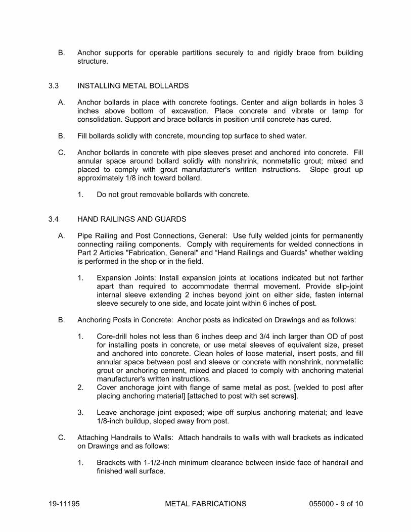
19-11195 METAL FABRICATIONS 055000 - 9 of 10
B. Anchor supports for operable partitions securely to and rigidly brace from buildingstructure.
3.3 INSTALLING METAL BOLLARDS
A. Anchor bollards in place with concrete footings. Center and align bollards in holes 3inches above bottom of excavation. Place concrete and vibrate or tamp forconsolidation. Support and brace bollards in position until concrete has cured.
B. Fill bollards solidly with concrete, mounding top surface to shed water.
C. Anchor bollards in concrete with pipe sleeves preset and anchored into concrete. Fillannular space around bollard solidly with nonshrink, nonmetallic grout; mixed andplaced to comply with grout manufacturer's written instructions. Slope grout upapproximately 1/8 inch toward bollard.
1. Do not grout removable bollards with concrete.
3.4 HAND RAILINGS AND GUARDS
A. Pipe Railing and Post Connections, General: Use fully welded joints for permanentlyconnecting railing components. Comply with requirements for welded connections inPart 2 Articles "Fabrication, General" and “Hand Railings and Guards” whether weldingis performed in the shop or in the field.
1. Expansion Joints: Install expansion joints at locations indicated but not fartherapart than required to accommodate thermal movement. Provide slip-jointinternal sleeve extending 2 inches beyond joint on either side, fasten internalsleeve securely to one side, and locate joint within 6 inches of post.
B. Anchoring Posts in Concrete: Anchor posts as indicated on Drawings and as follows:
1. Core-drill holes not less than 6 inches deep and 3/4 inch larger than OD of postfor installing posts in concrete, or use metal sleeves of equivalent size, presetand anchored into concrete. Clean holes of loose material, insert posts, and fillannular space between post and sleeve or concrete with nonshrink, nonmetallicgrout or anchoring cement, mixed and placed to comply with anchoring materialmanufacturer's written instructions.
2. Cover anchorage joint with flange of same metal as post, [welded to post afterplacing anchoring material] [attached to post with set screws].
3. Leave anchorage joint exposed; wipe off surplus anchoring material; and leave1/8-inch buildup, sloped away from post.
C. Attaching Handrails to Walls: Attach handrails to walls with wall brackets as indicatedon Drawings and as follows:
1. Brackets with 1-1/2-inch minimum clearance between inside face of handrail andfinished wall surface.

19-11195 METAL FABRICATIONS 055000 - 10 of 10
a. Use type of bracket with flange tapped for concealed anchorage tothreaded hanger bolt.
2. Locate brackets as indicated or, if not indicated, at spacing required to supportstructural loads.
3. For wood stud partitions, use hanger or lag bolts set into studs or wood backingbetween studs. Coordinate blocking with carpentry work to locate backingmembers.
4. For steel-framed partitions, use self-tapping screws fastened to steel framing orto concealed steel reinforcements. Coordinate backing with steel framedpartition work.
5. Use crush sleeves where fastening brackets to walls through gypsum board.
3.5 INSTALLING METAL BAR GRATINGS
A. General: Install gratings to comply with recommendations of referenced metal bargrating standards that apply to grating types and bar sizes indicated, includinginstallation clearances and standard anchoring details.
3.6 ADJUSTING AND CLEANING
A. Touchup Painting: Immediately after erection, clean field welds, bolted connections,and abraded areas. Paint uncoated and abraded areas with the same material asused for shop painting to comply with SSPC-PA 1 for touching up shop-paintedsurfaces.
1. Apply by brush or spray to provide a minimum 2.0-mil (0.05-mm) dry filmthickness.
B. Touchup Painting: Cleaning and touchup painting of field welds, bolted connections,and abraded areas of shop paint are specified in Division 09 painting Sections.
C. Galvanized Surfaces: Clean field welds, bolted connections, and abraded areas andrepair galvanizing to comply with ASTM A 780.
END OF SECTION

19-11195 METAL LADDERS 055133 - 1 of 4
SECTION 055133 METAL LADDERS
PART 1 - GENERAL
1.1 RELATED DOCUMENTS
A. Drawings and general provisions of the Contract, including General and Supplementary Conditions and Division 01 Specification Sections, apply to this Section.
1.2 SUMMARY
A. This Section includes the following:
1. Fixed aluminum exterior roof access ladders.
B. Related Sections include the following:
1. Division 09 Section “Non-Structural Metal Framing” for backing support for ladder wall anchorage concealed within other construction before ladder installation.
1.3 SUBMITTALS
A. Product Data: For each type of product indicated. Include construction details, material descriptions, and finishes.
B. Shop Drawings: Include plans, elevations, sections, and details of ladders and their connections. Show anchorage to adjoining Work.
1.4 PROJECT CONDITIONS
A. Field Measurements: Verify actual locations of walls and other construction contiguous with metal ladders by field measurements before fabrication and indicate measurements on Shop Drawings.
1. Established Dimensions: Where field measurements cannot be made without delaying the Work, establish dimensions and proceed with fabricating metal fabrications without field measurements. Coordinate wall and other contiguous construction to ensure that actual dimensions correspond to established dimensions.
1.5 COORDINATION
A. Coordinate installation of anchorages for metal ladders. Furnish setting drawings, templates, and directions for installing anchorages, including sleeves, inserts, anchor

19-11195 METAL LADDERS 055133 - 2 of 4
bolts, and items with integral anchors, that are to be embedded in concrete or masonry. Deliver such items to Project site in time for installation.
PART 2 - PRODUCTS
2.1 PERFORMANCE REQUIREMENTS
A. OSHA Requirements: Ladders shall comply with ANSI A14.3 and OSHA 1910.27.
B. California Building Code (CBC) Requirements: Comply with CBC Section 1011.15.
C. Structural Performance of Ladders: ladders, including landings, shall withstand the effects of loads and stresses within limits and under conditions specified in ANSI A14.3.
D. Thermal Movements: Allow for thermal movements from ambient and surface temperature changes acting on exterior metal fabrications by preventing buckling, opening of joints, overstressing of components, failure of connections, and other detrimental effects.
1. Temperature Change: 120 deg F ambient; 180 deg F material surfaces.
2.2 METALS, GENERAL
A. Metal Surfaces, General: Provide materials with smooth, flat surfaces, unless otherwise indicated. For metal fabrications exposed to view in the completed Work, provide materials without seam marks, roller marks, rolled trade names, or blemishes.
B. Ferrous Metals:
1. Steel Plates, Shapes, and Bars: ASTM A 36/A 36M. 2. Steel Tubing: ASTM A 500, cold-formed steel tubing. 3. Steel Pipe: ASTM A 53/A 53M, standard weight (Schedule 40) unless otherwise
indicated.
C. Nonferrous Metals:
1. Aluminum Plate and Sheet: ASTM B 209 (ASTM B 209M), Alloy 6061-T6. 2. Aluminum Extrusions: ASTM B 221 (ASTM B 221M), Alloy 6063-T6. 3. Aluminum-Alloy Rolled Tread Plate: ASTM B 632/B 632M, Alloy 6061-T6. 4. Aluminum Castings: ASTM B 26/B 26M, Alloy 443.0-F.
2.3 MANUFACTURERS
A. Basis of Design Manufacturer: Where manufacturer and model are indicated for ladder types, Design, Drawings, and Specifications are based on products manufactured by the following:
1. O’Keefe’s Inc.

19-11195 METAL LADDERS 055133 - 3 of 4
a. Subject to requirements, provide products indicated or comparableproducts manufactured by one of the following:
1) ACL Industries, Inc.2) Alco-Lite Industrial Products.3) Precision Ladders, LLC.
B. Source Limitations: Obtain ladders from a single source and from a single Manufacturer.
2.4 EXTERIOR LADDERS
A. Interior Ladders: Manufactured, fixed, interior, straight run, aluminum ladders.
B. Basis of Design: Drawings and Specifications are based on the following:
1. O'Keeffe's Inc.; Model 503 Tubular Rail Low Parapet Access Ladder withPlatform & Return.
C. Ladder Components:
1. Side Rails: Manufacturer’s standard continuous extruded-aluminum channels ortubes, not less than 3 inches deep, 1 inch wide, and 1/8 inch thick.
a. Side Rail Spacing: Manufacturer’s standard, 18 inches minimum/22”inches maximum between side rails.
2. Rungs: Manufacturer’s standard extruded-aluminum tube rungs not less than 1-1/4 square and not less than 1/8 inch thick, with ribbed tread surfaces, andcapable of withstanding a 1,000 pound point load without deformation or failure.
a. Fit rungs in centerline of side rails; fasten by stainless-steel fasteners,welding, or with brackets and aluminum rivets.
b. Space rungs 12 inches on center along side rails, 12 inches from top ofroof access curb, and not more than 12 inches above the floor.
3. Anchorage: Manufacturer’s standard aluminum floor and wall anchorage platesand brackets; wall anchorage brackets shall be spaced 60 inches on centermaximum and 12 inches maximum from the top of the ladder.
a. Wall brackets shall locate the ladder such that the centerline of rungs shallbe 7 inches minimum to the finished wall surface.
4. Walk-Through Rail and Roof Rail Extension: Not less than 3 feet 6 inches (1067mm) above the landing and shall be fitted with deeply serrated, square, tubulargrab rails.
5. Landing Platform: 1-1/2 inches (38 mm) or greater diameter, tubular aluminumguardrails and decks of serrated aluminum treads.
6. Security Doors: Formed 1/8 (3 mm) thick aluminum sheet. Security panels shallextend on both sides, perpendicular to the door face, to within 2 inches (51 mm)

19-11195 METAL LADDERS 055133 - 4 of 4
of the wall. Security door shall be furnished with continuous aluminum piano hinge and heavy duty forged steel locking hasps.
7. Floor Mounted Standard Bracket: 3/16” THK angle.8. Finish: Mill finish.
2.5 FASTENERS
A. Provide Type 304 stainless-steel fasteners for fastening aluminum ladders to in-placeconstruction; select fasteners for type, grade, and class required.
PART 3 - EXECUTION
3.1 EXAMINATION
A. Examine substrates, areas, and conditions, for compliance with requirements forinstallation tolerances and other conditions affecting performance of the Work.
B. Examine wall framing for backing to verify actual locations before ladder installation.
C. Proceed with installation only after unsatisfactory conditions have been corrected.
3.2 INSTALLATION
A. General: Comply with manufacturer's written installation instructions. Install ladderslevel and plumb. Secure ladders in position with manufacturer's recommendedanchoring devices.
B. Corrosion Protection: Coat concealed surfaces of aluminum that will come into contactwith grout, concrete, masonry, wood, or dissimilar metals with a heavy coat ofbituminous paint.
3.3 PROTECTION
A. Protect installed products until completion of project.
END OF SECTION

19-11195 ROUGH CARPENTRY 06 10 00 - 1 of 8
SECTION 061000 ROUGH CARPENTRY
PART 1 - GENERAL
1.1 RELATED DOCUMENTS
A. Drawings and general provisions of the Contract, including General and Supplementary conditions and Division 01 Specification Sections, apply to this Section.
1.2 SUMMARY
A. Section includes:
1. Framing with dimension lumber. 2. Framing with timber. 3. Rooftop equipment bases and support curbs. 4. Wood blocking and nailers. 5. Wood sleepers.
B. Related Sections:
1. Division 03 Section “Post Installed Concrete Anchors” for post installed anchors in concrete and/or masonry.
1.3 REFERENCED CODES AND STANDARDS
A. California Code of Regulations, Title 24, Part 2, California Building Code, 2016 Edition.
B. American Wood Council (AWC):
1. National Design Specification for Wood Construction with commentary, September 30, 2014 (ANSI/AWC NDS-2015).
2. Special Design Provisions for Wind and Seismic with commentary, September 8, 2014 (ANSI/AWC SDPWS-2015).
1.4 DEFINITIONS
A. Exposed Framing: Framing not concealed by other construction.
B. Dimension Lumber: Lumber of 2 inches nominal or greater but less than 5 inches nominal in least dimension.
C. Timber: Lumber of 5 inches nominal or greater in least dimension.
D. Lumber grading agencies, and the abbreviations used to reference them, include the following:

19-11195 ROUGH CARPENTRY 06 10 00 - 2 of 8
1. NLGA: National Lumber Grades Authority. 2. WCLIB: West Coast Lumber Inspection Bureau. 3. WWPA: Western Wood Products Association.
1.5 DELIVERY, STORAGE, AND HANDLING
A. Stockpile materials sufficiently in advance of need to assure their availability in a timely manner for Work.
B. Use extreme care in off-loading of lumber to prevent damage, splitting, and breaking of materials.
C. Stack wood products flat with spacers beneath and between each bundle to provide air circulation. Protect wood products from weather by covering with waterproof sheeting, securely anchored. Provide for air circulation around stacks and under coverings.
D. Identify framing lumber by grade, and store each grade separately from other grades.
PART 2 - PRODUCTS
2.1 WOOD PRODUCTS, GENERAL
A. Lumber: DOC PS 20 and applicable rules of grading agencies indicated. If no grading agency is indicated, provide lumber that complies with the applicable rules of any rules-writing agency certified by the ALSC Board of Review. Provide lumber graded by an agency certified by the ALSC Board of Review to inspect and grade lumber under the rules indicated.
1. Factory mark each piece of lumber with grade stamp of grading agency. 2. Provide dressed lumber, S4S, unless otherwise indicated.
B. Moisture Content of Lumber: 19 percent maximum unless otherwise indicated.
2.2 WOOD-PRESERVATIVE-TREATED LUMBER
A. Preservative Treatment by Pressure Process: AWPA U1, Use Category UC2.
1. Preservative Chemicals: Acceptable to authorities having jurisdiction and containing no arsenic or chromium.
B. Kiln-dry lumber after treatment to a maximum moisture content of 19 percent. Do not use material that is warped or does not comply with requirements for untreated material.
C. Mark lumber with treatment quality mark of an inspection agency approved by the ALSC Board of Review.
D. Application: Treat items indicated on Drawings, and the following:

19-11195 ROUGH CARPENTRY 06 10 00 - 3 of 8
1. Wood cants, nailers, curbs, equipment support bases, blocking, stripping, andsimilar members in connection with roofing, flashing, vapor barriers, andwaterproofing.
2. Wood sills, sleepers, blocking, furring, stripping, and similar concealed membersin contact with masonry or concrete.
3. Wood framing and furring attached directly to the interior of below-grade exteriormasonry or concrete walls.
4. Wood framing members that are less than 18 inches above the ground incrawlspaces or unexcavated areas.
5. Wood floor plates that are installed over concrete slabs-on-grade.
2.3 DIMENSION LUMBER FRAMING
A. All Framing Lumber: Provide lumber of grade and species meeting or exceeding thefollowing standards of quality:
1. Douglas Fir, WCLIB or WWPA, No. 1 or better, unless otherwise indicated onDrawings.
2.4 TIMBER FRAMING
A. Comply with the following requirements, according to grading rules of grading agencyindicated:
1. Douglas Fir, WCLIB or WWPA, No. 1 or better, unless otherwise indicated onDrawings.
2.5 MISCELLANEOUS WOOD PRODUCTS
A. General: Provide miscellaneous lumber as indicated on Drawings, as required forproject conditions, and as required for support or attachment of other construction.
B. Lumber Species and Grade: Provide lumber species and grade matching framinglumber.
1. For blocking not used for attachment of other construction, Utility or Stud gradelumber may be used provided that it is cut and selected to eliminate defects thatwill interfere with its attachment and purpose.
2. For blocking and nailers used for attachment of other construction, select and cutlumber to eliminate knots and other defects that will interfere with attachment ofother work.
C. Boards: Provide lumber of 19 percent maximum moisture content (S-DRY).
1. Exposed Boards: Where boards will not be concealed by other work or wherepainted finish is indicated, provide Select Merchantable Boards per WCLIP rules.
2. Concealed Boards: Where boards will be concealed by other work, provide anyspecies graded construction boards or WCLIP No. 1 or better.

19-11195 ROUGH CARPENTRY 06 10 00 - 4 of 8
D. For furring strips for installing plywood or hardboard paneling, select boards with noknots capable of producing bent-over nails and damage to paneling.
2.6 FASTENERS
A. General: Provide fasteners of size and type indicated that comply with requirementsspecified in this Article for material and manufacture.
1. Fasteners in contact with preservative treated or fire retardant treated wood,including nuts and washers, shall be of hot dipped galvanized steel, stainlesssteel, or silicon bronze; the coating weights for zinc-coated fasteners shall be inaccordance with ASTM A 153. Fasteners other than nails, timber rivets, woodscrews, and lag screws shall be permitted to be of mechanically deposited zinc-coated steel with coating weights in accordance with ASTM B 695, Class 55minimum; comply with requirements of 2016 CBC 2304.10.5.
B. Nails, Brads, and Staples: ASTM F 1667.
C. Power-Driven Fasteners: Fastener systems with an evaluation report acceptable toauthorities having jurisdiction, based on ICC-ES AC70.
D. Wood Screws: ASME B18.6.1.
E. Lag Bolts: ASME B18.2.1 (ASME B18.2.3.8M).
F. Bolts: Steel bolts complying with ASTM A 307, Grade A (ASTM F 568M, PropertyClass 4.6); with ASTM A 563 (ASTM A 563M) hex nuts and, where indicated, flatwashers.
G. Post Installed Concrete Anchors: Fabricated from corrosion-resistant materials;manufacturer, size, and type as indicated on Drawings and specified in Division 03Section “Post Installed Concrete Anchors.”
1. Carbon-steel components, zinc plated to comply with ASTM B 633,Class Fe/Zn 5.
2. Stainless steel with bolts and nuts complying with ASTM F 593 and ASTM F 594,Alloy Group 1 or 2 (ASTM F 738M and ASTM F 836M, Grade A1 or A4).
2.7 METAL FRAMING ANCHORS AND HARDWARE
A. General: Connectors in contact with preservative treated or fire retardant treated woodshall be of hot dipped galvanized steel or stainless steel; the coating weights for zinc-coated connectors shall be in accordance with ASTM A 153; comply with requirementsof 2016 CBC 2304.10.5.
B. Basis of Design Manufacturer: Provide products as indicated on Drawings manufactured by the following:
1. Simpson Strong-Tie Co., Inc.

19-11195 ROUGH CARPENTRY 06 10 00 - 5 of 8
C. Material: Galvanized steel sheet, hot-dip, zinc-coated steel sheet complying withASTM A 653/A 653M, G60 (Z180) coating designation.
1. Use for interior locations unless otherwise indicated.
2.8 MISCELLANEOUS MATERIALS
A. Sill-Sealer Gaskets: Closed-cell neoprene foam, 1/4 inch thick, selected from manufacturer's standard widths to suit width of sill members indicated.
B. Adhesives for Gluing Furring and Sleepers to Concrete or Masonry: Formulationcomplying with ASTM D 3498 that is approved for use indicated by adhesivemanufacturer.
1. Use adhesives that have a VOC content of 70 g/L or less when calculatedaccording to 40 CFR 59, Subpart D (EPA Method 24).
C. Water-Repellent Preservative: NWWDA-tested and -accepted formulation containing3-iodo-2-propynyl butyl carbamate, combined with an insecticide containingchloropyrifos as its active ingredient.
PART 3 - EXECUTION
3.1 INSTALLATION, GENERAL
A. General: Install framing as indicated on drawings, as herein specified, and as requiredto comply with regulatory agencies and American Forest and Paper Association(AF&PA) document WCD 1 "Details for Conventional Wood Frame Construction".Notes and details on Drawings shall take precedence over these specifications.
B. Set rough carpentry to required levels and lines, with members plumb, true to line, cut,and fitted. Fit rough carpentry to other construction; scribe and cope as needed foraccurate fit. Locate furring, nailers, blocking, grounds, and similar supports to complywith requirements for attaching other construction.
C. Install plywood backing panels by fastening to studs; coordinate locations with utilitiesrequiring backing panels. Install plywood backing panels with classification marking oftesting agency exposed to view.
D. Install metal framing anchors to comply with manufacturer's written instructions. Installfasteners through each fastener hole.
E. Install sill sealer gasket to form continuous seal between sill plates and foundationwalls.
F. Do not splice structural members between supports, unless otherwise indicated.
G. Provide blocking and framing as indicated and as required to support facing materials,fixtures, specialty items, and trim.

19-11195 ROUGH CARPENTRY 06 10 00 - 6 of 8
1. Provide metal clips for fastening gypsum board or lath at corners andintersections where framing or blocking does not provide a surface for fasteningedges of panels. Space clips not more than 16 inches on center.
H. Provide fire blocking in furred spaces, stud spaces, and other concealed cavities inaccordance with 2016 CBC Section 718 “Concealed Spaces” and as follows:
1. Fire block furred spaces of walls, at each floor level, at ceiling, and at not morethan 96 inches on center with solid wood blocking or noncombustible materialsaccurately fitted to close furred spaces.
2. Fire block concealed spaces of wood-framed walls and partitions at each floorlevel, at ceiling line of top story, and at not more than 96 inches on center Wherefire blocking is not inherent in framing system used, provide closely fitted solidwood blocks of same width as framing members and 2-inch nominal- thickness.
I. Sort and select lumber so that natural characteristics will not interfere with installationor with fastening other materials to lumber. Do not use materials with defects thatinterfere with function of member or pieces that are too small to use with minimumnumber of joints or optimum joint arrangement.
J. Comply with AWPA M4 for applying field treatment to cut surfaces of preservative-treated lumber.
1. Use inorganic boron for items that are continuously protected from liquid water.2. Use copper naphthenate for items not continuously protected from liquid water.
K. Securely attach rough carpentry work to substrate by anchoring and fastening asindicated on Drawings and complying with the following:
1. ICC ESR-1539 for power-driven staples and nails.2. 2016 CBC Table 2304.10.1 “Fastening Schedule.”
L. Use common wire nails, unless otherwise indicated. Select fasteners of size that willnot fully penetrate members where opposite side will be exposed to view or will receivefinish materials. Make tight connections between members. Install fasteners withoutsplitting wood; do not countersink nail heads, unless otherwise indicated.
M. Fasteners and connectors in contact with preservative treated or fire retardant treatedwood shall be corrosion resistant as specified under Part 2 product requirements.
3.2 WOOD GROUND, SLEEPER, BLOCKING, AND NAILER INSTALLATION
A. Install where indicated and where required for screeding or attaching other work. Formto shapes indicated and cut as required for true line and level of attached work.Coordinate locations with other work involved.
B. Attach items to substrates to support applied loading. Recess bolts and nuts flush withsurfaces, unless otherwise indicated.

19-11195 ROUGH CARPENTRY 06 10 00 - 7 of 8
C. Provide permanent grounds of dressed, pressure-preservative-treated, key-beveledlumber not less than 1-1/2 inches wide and of thickness required to bring face ofground to exact thickness of finish material. Remove temporary grounds when nolonger required.
3.3 WALL AND PARTITION FRAMING INSTALLATION
A. General: Provide single bottom plate and double top plates using members ofminimum 2-inch nominal thickness whose widths equal that of studs, except single topplate may be used for non-load-bearing partitions. Fasten plates to supportingconstruction, unless otherwise indicated.
1. Provide wall framing members of size and spacing indicated on Drawings.2. Provide continuous horizontal blocking at mid-height of partitions more than 96
inches high, using members of 2-inch nominal thickness and of same width aswall or partitions.
B. Construct corners and intersections with three or more studs.
C. Frame openings as indicated on Drawings with multiple studs and headers. Providenailed header members of thickness equal to width of studs. Support headers ondouble-jamb studs for openings 60 inches and less in width, and triple-jamb studs forwider openings. Provide headers of depth indicated.
3.4 CEILING JOIST AND RAFTER FRAMING INSTALLATION
A. Ceiling Joists: Install ceiling joists with crown edge up and complying with requirements specified above for floor joists. Face nail to ends of parallel rafters.
1. Where ceiling joists are at right angles to rafters, provide additional short joistsparallel to rafters from wall plate to first joist; nail to ends of rafters and to topplate and nail to first joist or anchor with framing anchors or metal straps.Provide 1-by-8-inch nominal- size or 2-by-4-inch nominal- size stringers spaced48 inches on center crosswise over main ceiling joists.
B. Rafters: Notch to fit exterior wall plates and use metal framing anchors. Double raftersto form headers and trimmers at openings in roof framing, if any, and support withmetal hangers. Where rafters abut at ridge, place directly opposite each other and nailto ridge member or use metal ridge hangers.
1. At valleys, provide double-valley rafters of size indicated or, if not indicated, ofsame thickness as regular rafters and 2 inches deeper. Bevel ends of jackrafters for full bearing against valley rafters.
2. At hips, provide hip rafter of size indicated or, if not indicated, of same thicknessas regular rafters and 2 inches deeper. Bevel ends of jack rafters for full bearingagainst hip rafter.
C. Provide collar beams (ties) as indicated or, if not indicated, provide 1-by-6-inch nominalsize boards between every third pair of rafters, but not more than 48 inches on center.

19-11195 ROUGH CARPENTRY 06 10 00 - 8 of 8
Locate below ridge member, at third point of rafter span. Cut ends to fit roof slope and nail to rafters.
D. Provide special framing as indicated for eaves, overhangs, dormers, and similarconditions, if any.
3.5 PROTECTION
A. Use all necessary means to protect the installed work and materials of all other trades.In the event of damage, immediately make all repairs and replacements necessary to,the approval of the Architect and at no additional cost to the Owner.
B. Protect rough carpentry from weather. If, despite protection, rough carpentry becomeswet, apply EPA-registered borate treatment. Apply borate solution by spraying tocomply with EPA-registered label.
END OF SECTION

19-11195 MISCELLANEOUS ROUGH CARPENTRY 061053 - 1 of 7
SECTION 061053 MISCELLANEOUS ROUGH CARPENTRY
PART 1 - GENERAL
1.1 RELATED DOCUMENTS
A. Drawings and general provisions of the contract, including General and Supplementary Conditions and Division 01 Specification Sections, apply to this Section.
1.2 SUMMARY
A. This Section includes the following:
1. Framing with dimension lumber. 2. Wood blocking and nailers. 3. Wood furring and grounds. 4. Wood sleepers. 5. Miscellaneous plywood sheathing.
B. Related Sections:
1. Division 03 Section “Post Installed Concrete Anchors” for post installed anchors in concrete and/or masonry.
2. Division 26 Electrical specifications as applicable for plywood backing panels for telecommunications backboard panels.
1.3 DEFINITIONS
A. Dimension Lumber: Lumber of 2 inches nominal or greater but less than 5 inches nominal in least dimension.
B. Timber: Lumber of 5 inches nominal or greater in least dimension.
C. Lumber grading agencies, and the abbreviations used to reference them, include the following:
1. NHLA: National Hardwood Lumber Association. 2. NLGA: National Lumber Grades Authority. 3. WCLIB: West Coast Lumber Inspection Bureau. 4. WWPA: Western Wood Products Association.
1.4 SUBMITTALS
A. Product Data: For each type of process and factory-fabricated product. Indicate component materials and dimensions and include construction and application details.

19-11195 MISCELLANEOUS ROUGH CARPENTRY 061053 - 2 of 7
1. Include data for wood-preservative treatment from chemical treatmentmanufacturer and certification by treating plant that treated materials comply withrequirements. Indicate type of preservative used and net amount of preservativeretained.
2. For products receiving a waterborne treatment, include statement that moisturecontent of treated materials was reduced to levels specified before shipment toProject site.
3. Include copies of warranties from chemical treatment manufacturers for eachtype of treatment.
B. Research/Evaluation Reports: From ICC-ES or IAPMO ES, for the following,:
1. Wood-preservative-treated wood.2. Engineered wood products.3. Power-driven fasteners.4. Powder-actuated fasteners.5. Post installed concrete anchors.6. Metal framing anchors.
1.5 DELIVERY, STORAGE, AND HANDLING
A. Stack lumber flat with spacers between each bundle to provide air circulation. Providefor air circulation around stacks and under coverings.
B. Stack plywood and other panels flat with spacers between each bundle to provide aircirculation. Provide for air circulation around stacks and under coverings.
PART 2 - PRODUCTS
2.1 WOOD PRODUCTS, GENERAL
A. Lumber: DOC PS 20 and applicable rules of grading agencies indicated. If no gradingagency is indicated, provide lumber that complies with the applicable rules of any rules-writing agency certified by the ALSC Board of Review. Provide lumber graded by anagency certified by the ALSC Board of Review to inspect and grade lumber under therules indicated.
1. Factory mark each piece of lumber with grade stamp of grading agency.2. Where nominal sizes are indicated, provide actual sizes required by DOC PS 20
for moisture content specified. Where actual sizes are indicated, they areminimum dressed sizes for dry lumber.
3. Provide dressed lumber, S4S, unless otherwise indicated.
B. Moisture Content of Lumber: 19 percent maximum unless otherwise indicated.
2.2 WOOD-PRESERVATIVE-TREATED MATERIALS
A. Preservative Treatment by Pressure Process: AWPA U1, Use Category UC2.
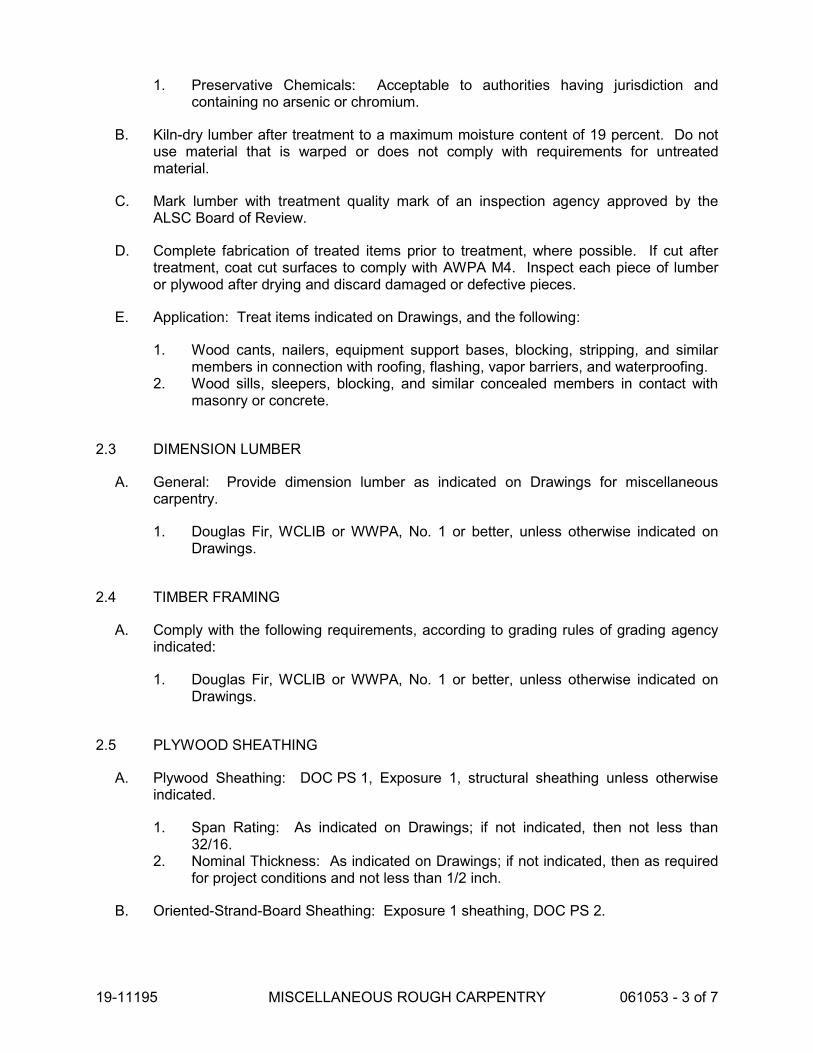
19-11195 MISCELLANEOUS ROUGH CARPENTRY 061053 - 3 of 7
1. Preservative Chemicals: Acceptable to authorities having jurisdiction and containing no arsenic or chromium.
B. Kiln-dry lumber after treatment to a maximum moisture content of 19 percent. Do notuse material that is warped or does not comply with requirements for untreatedmaterial.
C. Mark lumber with treatment quality mark of an inspection agency approved by theALSC Board of Review.
D. Complete fabrication of treated items prior to treatment, where possible. If cut aftertreatment, coat cut surfaces to comply with AWPA M4. Inspect each piece of lumberor plywood after drying and discard damaged or defective pieces.
E. Application: Treat items indicated on Drawings, and the following:
1. Wood cants, nailers, equipment support bases, blocking, stripping, and similarmembers in connection with roofing, flashing, vapor barriers, and waterproofing.
2. Wood sills, sleepers, blocking, and similar concealed members in contact withmasonry or concrete.
2.3 DIMENSION LUMBER
A. General: Provide dimension lumber as indicated on Drawings for miscellaneouscarpentry.
1. Douglas Fir, WCLIB or WWPA, No. 1 or better, unless otherwise indicated onDrawings.
2.4 TIMBER FRAMING
A. Comply with the following requirements, according to grading rules of grading agencyindicated:
1. Douglas Fir, WCLIB or WWPA, No. 1 or better, unless otherwise indicated onDrawings.
2.5 PLYWOOD SHEATHING
A. Plywood Sheathing: DOC PS 1, Exposure 1, structural sheathing unless otherwiseindicated.
1. Span Rating: As indicated on Drawings; if not indicated, then not less than32/16.
2. Nominal Thickness: As indicated on Drawings; if not indicated, then as requiredfor project conditions and not less than 1/2 inch.
B. Oriented-Strand-Board Sheathing: Exposure 1 sheathing, DOC PS 2.

19-11195 MISCELLANEOUS ROUGH CARPENTRY 061053 - 4 of 7
1. Span Rating: As indicated on Drawings; if not indicated, then not less than32/16.
2. Nominal Thickness: As indicated on Drawings; if not indicated, then as requiredfor project conditions and not less than 1/2 inch.
C. Factory mark panels to indicate compliance with applicable standard.
2.6 MISCELLANEOUS WOOD PRODUCTS
A. General: Provide miscellaneous lumber as indicated on Drawings, as required forproject conditions, and as required for support or attachment of other construction.
B. Lumber Species and Grade: Provide lumber species and grade matching framinglumber.
1. For blocking not used for attachment of other construction, Utility or Stud gradelumber may be used provided that it is cut and selected to eliminate defects thatwill interfere with its attachment and purpose.
2. For blocking and nailers used for attachment of other construction, select and cutlumber to eliminate knots and other defects that will interfere with attachment ofother work.
C. Boards: Provide lumber of 19 percent maximum moisture content (S-DRY).
1. Exposed Boards: Where boards will not be concealed by other work or wherepainted finish is indicated, provide Select Merchantable Boards per WCLIP rules.
2. Concealed Boards: Where boards will be concealed by other work, provide anyspecies graded construction boards or WCLIP No. 1 or better.
D. For furring strips for installing plywood or hardboard paneling, select boards with noknots capable of producing bent-over nails and damage to paneling.
2.7 FASTENERS
A. General: Provide fasteners of size and type indicated that comply with requirementsspecified in this Article for material and manufacture.
1. Fasteners in contact with preservative treated or fire retardant treated wood,including nuts and washers, shall be of hot dipped galvanized steel, stainlesssteel, or silicon bronze; the coating weights for zinc-coated fasteners shall be inaccordance with ASTM A 153. Fasteners other than nails, timber rivets, woodscrews, and lag screws shall be permitted to be of mechanically deposited zinc-coated steel with coating weights in accordance with ASTM B 695, Class 55minimum; comply with requirements of 2016 CBC 2304.10.5.
B. Nails, Brads, and Staples: ASTM F 1667.
C. Power-Driven Fasteners: Fastener systems with an evaluation report acceptable toauthorities having jurisdiction, based on ICC-ES AC70.
D. Wood Screws: ASME B18.6.1.

19-11195 MISCELLANEOUS ROUGH CARPENTRY 061053 - 5 of 7
E. Lag Bolts: ASME B18.2.1 (ASME B18.2.3.8M).
F. Bolts: Steel bolts complying with ASTM A 307, Grade A (ASTM F 568M, PropertyClass 4.6); with ASTM A 563 (ASTM A 563M) hex nuts and, where indicated, flatwashers.
G. Post Installed Concrete Anchors: Fabricated from corrosion-resistant materials;manufacturer, size, and type as indicated on Drawings and specified in Division 03Section “Post Installed Concrete Anchors.”
1. Carbon-steel components, zinc plated to comply with ASTM B 633,Class Fe/Zn 5.
2. Stainless steel with bolts and nuts complying with ASTM F 593 and ASTM F 594,Alloy Group 1 or 2 (ASTM F 738M and ASTM F 836M, Grade A1 or A4).
2.8 METAL FRAMING ANCHORS AND HARDWARE
A. General: Connectors in contact with preservative treated or fire retardant treated woodshall be of hot dipped galvanized steel or stainless steel; the coating weights for zinc-coated connectors shall be in accordance with ASTM A 153; comply with requirementsof 2016 CBC 2304.10.5.
B. Basis of Design Manufacturer: Provide products as indicated on Drawings manufactured by the following:
1. Simpson Strong-Tie Co., Inc.
C. Material: Galvanized steel sheet, hot-dip, zinc-coated steel sheet complying withASTM A 653/A 653M, G60 (Z180) coating designation.
1. Use for interior locations unless otherwise indicated.
PART 3 - EXECUTION
3.1 INSTALLATION, FRAMING, BLOCKING, AND NAILERS
A. General: Install framing as indicated on drawings, as herein specified, and as requiredto comply with regulatory agencies and American Forest and Paper Association(AF&PA) document WCD 1 "Details for Conventional Wood Frame Construction". Notes and details on Drawings shall take precedence over these specifications.
B. Set carpentry to required levels and lines, with members plumb, true to line, cut, andfitted. Fit carpentry to other construction; scribe and cope as needed for accurate fit.Locate nailers, blocking, and similar supports to comply with requirements for attachingother construction.
C. Where wood-preservative-treated lumber is installed adjacent to metal decking, installcontinuous flexible flashing separator between wood and metal decking.

19-11195 MISCELLANEOUS ROUGH CARPENTRY 061053 - 6 of 7
D. Framing Requirements: Comply with requirements of the California Building Code,Chapter 23 unless otherwise indicated.
E. Metal Framing Anchors: Install metal framing anchors to comply with manufacturer'swritten instructions. Install fasteners through each fastener hole.
F. Do not splice structural members between supports, unless otherwise indicated.
G. Provide blocking and framing as indicated and as required to support facing materials,fixtures, specialty items, and trim.
H. Provide fire blocking in furred spaces, stud spaces, and other concealed cavities inaccordance with 2016 CBC Section 718 “Concealed Spaces” and as follows:
1. Fire block concealed spaces of wood-framed walls and partitions at each floorlevel, at ceiling line of top story, and at not more than 96 inches on center Wherefire blocking is not inherent in framing system used, provide closely fitted solidwood blocks of same width as framing members and 2-inch nominal- thickness.
I. Sort and select lumber so that natural characteristics will not interfere with installationor with fastening other materials to lumber. Do not use materials with defects thatinterfere with function of member or pieces that are too small to use with minimumnumber of joints or optimum joint arrangement.
J. Comply with AWPA M4 for applying field treatment to cut surfaces of preservative-treated lumber.
K. Securely attach carpentry work to substrate by anchoring and fastening as indicated,complying with the following:
1. ICC ESR-1539 for power-driven staples and nails.2. 2016 CBC Table 2304.10.1 “Fastening Schedule.”
L. Use steel common nails unless otherwise indicated. Select fasteners of size that willnot fully penetrate members where opposite side will be exposed to view or will receivefinish materials. Make tight connections between members. Install fasteners withoutsplitting wood. Drive nails snug but do not countersink nail heads unless otherwiseindicated.
M. Install blocking where indicated and where required for attaching other work. Form toshapes indicated and cut as required for true line and level of attached work.Coordinate locations with other work involved. Attach items to substrates to supportapplied loading. Recess bolts and nuts flush with surfaces, unless otherwise indicated.
3.2 PLYWOOD PANEL INSTALLATION
A. General: Comply with applicable recommendations in APA Form No. E30, "Engineered Wood Construction Guide," for types of structural-use panels and applications indicated.

19-11195 MISCELLANEOUS ROUGH CARPENTRY 061053 - 7 of 7
B. Do not use materials with defects that impair quality of sheathing or pieces that are toosmall to use with minimum number of joints or optimum joint arrangement. Arrangejoints so that pieces do not span between fewer than three support members.
C. Cut panels at penetrations, edges, and other obstructions of work; fit tightly againstabutting construction unless otherwise indicated.
D. Coordinate sheathing installation with installation of materials installed over sheathingso sheathing is not exposed to precipitation or left exposed at end of the workday whenrain is forecast.
E. Install plywood backing panels by fastening to studs; coordinate locations with utilitiesrequiring backing panels.
F. Fastening Methods: Fasten panels to supports with nails or screws. Use common wirenails unless otherwise indicated. Select fasteners of size that will not fully penetratemembers where opposite side will be exposed to view or will receive finish materials.Make tight connections. Install fasteners without splitting wood.
1. Securely attach to framing and blocking by fastening as indicated, complying withthe following:
a. ICC ESR-1539 for power-driven staples and nails.b. 2016 CBC Table 2304.10.1 “Fastening Schedule.”
3.3 PROTECTION
A. Protect miscellaneous rough carpentry from weather. If, despite protection,miscellaneous rough carpentry becomes wet, apply EPA-registered borate treatment.Apply borate solution by spraying to comply with EPA-registered label.
END OF SECTION


19-11195 SHEATHING 06 16 00 - 1 of 3
SECTION 061600 SHEATHING
PART 1 - GENERAL
1.1 RELATED DOCUMENTS
A. Drawings and general provisions of the Contract, including General and Supplementary Conditions and Division 01 Specification Sections, apply to this Section.
1.2 SUMMARY
A. This Section includes the following:
1. Wall sheathing. 2. Roof sheathing.
B. Related Sections include the following:
1. Division 06 Section "Rough Carpentry" for plywood backing panels. 2. Division 07 Section “Weather Resistive Barriers”.
1.3 DELIVERY, STORAGE, AND HANDLING
A. Stack plywood and other panels flat with spacers between each bundle to provide air circulation. Provide for air circulation around stacks and under coverings.
PART 2 - PRODUCTS
2.1 ROOF AND WALL SHEATHING
A. Plywood Sheathing: Either DOC PS 1 or DOC PS 2, Exposure 1, structural sheathing unless otherwise indicated.
1. Span Rating: As indicated on Drawings. 2. Nominal Thickness: As indicated on Drawings.
B. Factory mark panels to indicate compliance with applicable standard.

19-11195 SHEATHING 06 16 00 - 2 of 3
2.2 FASTENERS
A. General: Provide fasteners of size and type indicated that comply with requirementsspecified in this Article for material and manufacture.
1. For roof and wall sheathing, provide fasteners with hot-dip zinc coatingcomplying with ASTM A 153/A 153M.
B. Nails, Brads, and Staples: ASTM F 1667.
C. Power-Driven Fasteners: NES NER-272.
D. Wood Screws: ASME B18.6.1.
PART 3 - EXECUTION
3.1 INSTALLATION
A. Do not use materials with defects that impair quality of sheathing or pieces that are toosmall to use with minimum number of joints or optimum joint arrangement.
B. Cut panels at penetrations, edges, and other obstructions of work; fit tightly againstabutting construction, unless otherwise indicated.
C. Securely attach to substrate by fastening as indicated on Drawings complying with thefollowing:
1. NES NER-272 for power-driven fasteners.
D. Use common wire nails, unless otherwise indicated. Select fasteners of size that willnot fully penetrate members where opposite side will be exposed to view or will receivefinish materials. Make tight connections. Install fasteners without splitting wood.
E. Coordinate wall and roof sheathing installation with flashing and joint-sealantinstallation so these materials are installed in sequence and manner that preventexterior moisture from passing through completed assembly.
F. Coordinate sheathing installation with installation of materials installed over sheathingso sheathing is not exposed to precipitation or left exposed at end of the workday whenrain is forecast.
19-11195 SHEATHING 06 16 00 - 3 of 3
G. General: Comply with applicable recommendations in APA Form No. E30S,"Engineered Wood Construction Guide," for types of structural-use panels andapplications indicated.
H. Fastening Methods: Nail wall and roof sheathing panels to wood framing. Spacepanels 1/8 inch apart at edges and ends.
END OF SECTION


19-11195 MEMBRANE REROOFING PREPARATION 07 01 50 - 1 of 4
SECTION 070150 MEMBRANE REROOFING PREPARATION
PART 1 - GENERAL
1.1 RELATED DOCUMENTS
A. Drawings and general provisions of the Contract, including General andSupplementary Conditions and Division 1 Specification Sections, apply to this Section.
1.2 SUMMARY
A. This Section includes the following:
1. Roof tear-off.2. Removal of base flashings and edge flashings.
1.3 MATERIALS OWNERSHIP
A. Except for items or materials indicated to be reused, reinstalled, or otherwise indicatedto remain Owner's property, demolished materials shall become Contractor's propertyand shall be removed from Project site and disposed of legally.
1.4 DEFINITIONS
A. Roofing Terminology: Refer to ASTM D 1079 and glossary in NRCA's "The NRCARoofing and Waterproofing Manual" for definition of terms related to roofing work in thisSection.
B. Existing Membrane Roofing System: Single Ply roofing membrane, components andaccessories.
C. Substrate Board, Cover Board: Rigid board or panel products placed over the roofdeck that serve as thermal barriers, provide a smooth substrate, or serve as acomponent of a fire-resistance-rated roofing system.
D. Roof Tear-Off: Removal of existing membrane roofing system from deck.
E. Remove: Detach items from existing construction and legally dispose of them off-siteunless indicated to be removed and reinstalled.
1.5 SUBMITTALS
A. Product Data: For each type of product indicated.

19-11195 MEMBRANE REROOFING PREPARATION 07 01 50 - 2 of 4
B. Qualification Data: For Installer including certificate that Installer is licensed to performasbestos abatement.
1.6 QUALITY ASSURANCE
A. Regulatory Requirements: Comply with governing EPA notification regulations beforebeginning membrane roofing removal. Comply with hauling and disposal regulations ofauthorities having jurisdiction.
B. Reroofing Conference: Conduct conference at Project site to comply withrequirements in Division 1 Section "Project Management and Coordination." Reviewmethods and procedures related to roofing system including, but not limited to, thefollowing:
1. Meet with Owner; Architect; Owner's insurer if applicable; testing and inspectingagency representative; roofing system manufacturer's representative; roofingInstaller including project manager, superintendent, and foreman; and installerswhose work interfaces with or affects reroofing including installers of roofaccessories and roof-mounted equipment.
2. Review methods and procedures related to reroofing preparation, includingmembrane roofing system manufacturer's written instructions.
3. Review roof drainage during each stage of reroofing and review roof drainplugging and plug removal procedures.
4. Review and finalize construction schedule, and verify availability of materials,Installer's personnel, equipment, and facilities needed to make progress andavoid delays.
5. Review existing deck removal procedures and Owner notifications.6. Review procedures to determine condition and acceptance of existing deck for
reuse.7. Review base flashings, special roofing details, drainage, penetrations, equipment
curbs, and condition of other construction that will affect reroofing.8. Review HVAC shutdown and sealing of air intakes.9. Review shutdown of fire-suppression, -protection, and -alarm and -detection
systems.10. Review governing regulations and requirements for insurance and certificates if
applicable.11. Review existing conditions that may require notification of Owner or Architect
before proceeding.
1.7 PROJECT CONDITIONS
A. Owner will occupy portions of building immediately below reroofing area. Conductreroofing so Owner's operations will not be disrupted. Provide Owner with not lessthan 72 hours' notice of activities that may affect Owner's operations.
1. Coordinate work activities daily with Owner so Owner can place protective dustor water leakage covers over sensitive equipment or furnishings, shut downHVAC and fire-alarm or -detection equipment if needed, and evacuate occupantsfrom below the work area if desired.

19-11195 MEMBRANE REROOFING PREPARATION 07 01 50 - 3 of 4
B. Protect building to be reroofed, adjacent buildings, walkways, site improvements,exterior plantings, and landscaping from damage or soiling from reroofing operations.
C. Maintain access to existing walkways, corridors, and other adjacent occupied or usedfacilities. Do not block required exits or path from required exit to public right-of-way.Coordinate with requirements of authorities having jurisdiction.
D. Owner assumes no responsibility for condition of areas to be reroofed.
E. Weather Limitations: Proceed with reroofing preparation only when existing andforecasted weather conditions permit Work to proceed without water entering intoexisting roofing system or building.
F. If materials suspected of containing hazardous materials are encountered, do notdisturb; immediately notify Architect and Owner.
PART 2 - PRODUCTS
2.1 TEMPORARY ROOFING MATERIALS
A. As required by new Roof System Manufacturer.
PART 3 - EXECUTION
3.1 PREPARATION
A. Coordinate with Owner to shut down air intake equipment in the vicinity of the Work.Cover air intake louvers before proceeding with reroofing work that could affect indoorair quality or activate smoke detectors in the ductwork.
B. During removal operations, have sufficient and suitable materials on-site to facilitaterapid installation of temporary protection in the event of unexpected rain.
C. Maintain roof drains in functioning condition to ensure roof drainage at end of eachworkday. Prevent debris from entering or blocking roof drains and conductors. Useroof-drain plugs specifically designed for this purpose. Remove roof-drain plugs at endof each workday, when no work is taking place, or when rain is forecast.
1. If roof drains will be temporarily blocked or unserviceable due to roofing systemremoval or partial installation of new membrane roofing system, providealternative drainage method to remove water and eliminate ponding. Do notpermit water to enter into or under existing membrane roofing systemcomponents that are to remain.
D. Verify that rooftop utilities and service piping have been shut off before commencingWork.

19-11195 MEMBRANE REROOFING PREPARATION 07 01 50 - 4 of 4
3.2 ROOF TEAR-OFF
A. Roof Tear-Off: Remove existing roofing membrane and other membrane roofingsystem components down to the deck.
1. Remove roof insulation.
3.3 DECK PREPARATION
A. Inspect deck after tear-off of membrane roofing system.
1. Verify that substrate is visibly dry and free of moisture.
B. If deck surface is not suitable for receiving new roofing, or if structural integrity of deckis suspect, immediately notify Owner and/or Architect. Do not proceed with installationuntil directed by Owner and/or Architect.
3.4 EXISTING BASE FLASHINGS
A. Remove existing base flashings around parapets, curbs, walls, and penetrations asdirected by new roofing material manufacturer.
1. Clean substrates and designated surfaces of contaminants such as sheetmaterials, dirt, and debris.
3.5 DISPOSAL
A. Collect and place demolished materials in containers. Promptly dispose of demolishedmaterials. Do not allow demolished materials to accumulate on-site.
B. Transport demolished materials off Owner's property and legally dispose of them.
END OF SECTION

19-11195 SHEET METAL FLASHING AND TRIM 07 62 00 - 1 of 5
SECTION 076200 SHEET METAL FLASHING AND TRIM
PART 1 - GENERAL
1.1 RELATED DOCUMENTS
A. Drawings and general provisions of the Contract, including General and Supplementary Conditions and Division 1 Specification Sections, apply to this Section.
1.2 SUMMARY
A. This Section includes the following sheet metal flashing and trim: 1. Formed low-slope roof flashing and trim. 2. Formed wall flashing and trim. 3. Formed equipment support flashing. 4. Formed trim to match existing.
B. Related Sections include the following: Section 075420 for installing _____ single ply roofing membrane system.
1.3 PERFORMANCE REQUIREMENTS
A. General: Install sheet metal flashing and trim to withstand wind loads, structural movement, thermally induced movement, and exposure to weather without failing, rattling, leaking, and fastener disengagement.
B. Fabricate and install roof edge flashing and copings in accordance with recommendations in FMG Loss Prevention Data Sheet 1-49:
C. Thermal Movements: Provide sheet metal flashing and trim that allow for thermal movements resulting from the following maximum change (range) in ambient and surface temperatures by preventing buckling, opening of joints, hole elongation, overstressing of components, failure of joint sealants, failure of connections, and other detrimental effects. Provide clips that resist rotation and avoid shear stress as a result of sheet metal and trim thermal movements.
D. Water Infiltration: Provide sheet metal flashing and trim that do not allow water infiltration to building interior.
1.4 QUALITY ASSURANCE
A. Sheet Metal Flashing and Trim Standard: Comply with SMACNA's "Architectural Sheet Metal Manual." Conform to dimensions and profiles shown unless more stringent requirements are indicated.

19-11195 SHEET METAL FLASHING AND TRIM 07 62 00 - 2 of 5
1.5 DELIVERY, STORAGE, AND HANDLING
A. Unload, store, and install sheet metal flashing materials and fabrications in a manner to prevent bending, warping, twisting, and surface damage.
B. Stack materials on platforms or pallets, covered with suitable weathertight and ventilated covering. Do not store sheet metal flashing and trim materials in contact with other materials that might cause staining, denting, or other surface damage.
1.6 COORDINATION
A. Coordinate installation of sheet metal flashing and trim with interfacing and adjoining construction to provide a leakproof, secure, and noncorrosive installation.
PART 2 - PRODUCTS
2.1 SHEET METAL FLASHING AND TRIM
A. Zinc-Coated (Galvanized) Steel Sheet: ASTM A 653/A 653M, G90 coating designation; structural quality, mill phosphatized for field painting.
B. Coated Metal: .020@ thick membrane laminated to 24 gauge G-90 galvanized steel with acrylic backwash coating.
2.2 MISCELLANEOUS MATERIALS
A. General: Provide materials and types of fasteners, solder, welding rods, protective coatings, separators, sealants, and other miscellaneous items as required for complete sheet metal flashing and trim installation.
B. Fasteners: Wood screws, annular threaded nails, self-tapping screws, self-locking rivets and bolts, and other suitable fasteners designed to withstand design loads. 1. Fasteners for Flashing and Trim: Blind fasteners or self-drilling screws, gasketed, with
hex washer head.
C. Sealing Tape: Pressure-sensitive, 100 percent solids, polyisobutylene compound sealing tape with release-paper backing. Provide permanently elastic, nonsag, nontoxic, nonstaining tape.
D. Elastomeric Sealant: ASTM C 920, elastomeric polyurethane polymer sealant; of type, grade, class, and use classifications required to seal joints in sheet metal flashing and trim and remain watertight.
2.3 FABRICATION, GENERAL
A. General: Custom fabricate sheet metal flashing and trim to comply with recommendations in SMACNA's "Architectural Sheet Metal Manual" that apply to design, dimensions, metal, and other characteristics of item indicated. Shop fabricate items where practicable. Obtain field measurements for accurate fit before shop fabrication.

19-11195 SHEET METAL FLASHING AND TRIM 07 62 00 - 3 of 5
B. Fabricate sheet metal flashing and trim in thickness or weight needed to comply withperformance requirements, but not less than that specified for each application and metal.
C. Fabricate sheet metal flashing and trim without excessive oil canning, buckling, and tool marksand true to line and levels indicated, with exposed edges folded back to form hems.
D. Conceal fasteners and expansion provisions where possible on exposed-to-view sheet metalflashing and trim, unless otherwise indicated.
E. Fabricate cleats and attachment devices from same material as accessory being anchored orfrom compatible, noncorrosive metal.
1. Thickness: As recommended by SMACNA's "Architectural Sheet Metal Manual" andFMG Loss Prevention Data Sheet 1-49 for application but not less than thickness ofmetal being secured. 22 Gauge
2.4 LOW-SLOPE ROOF SHEET METAL FABRICATIONS
A. Roof Edge Flashings: Fabricate in minimum 96-inch- long, but not exceeding 10-foot- long,sections. Furnish with 6-inch- wide joint cover plates.
1. TPA Coated Metal: .020@ thick membrane laminated to 24 gauge G-90 galvanized steelwith acrylic backwash coating.
2. Eave and rake fabrication shall match existing Eave and Rake trim and eave gutter.Refer to drawings for shape and existing sheet metal remaining on building.
PART 3 - EXECUTION
3.1 EXAMINATION
A. Examine substrates, areas, and conditions, with Installer present, to verify actual locations,dimensions and other conditions affecting performance of work.
1. Verify that substrate is sound, dry, smooth, clean, sloped for drainage, and securelyanchored.
2. Proceed with installation only after unsatisfactory conditions have been corrected.
3.2 INSTALLATION, GENERAL
A. General: Anchor sheet metal flashing and trim and other components of the Work securely inplace, with provisions for thermal and structural movement. Use fasteners, solder, weldingrods, protective coatings, separators, sealants, and other miscellaneous items as required tocomplete sheet metal flashing and trim system.
1. Torch cutting of sheet metal flashing and trim is not permitted.

19-11195 SHEET METAL FLASHING AND TRIM 07 62 00 - 4 of 5
B. Metal Protection: Where dissimilar metals will contact each other or corrosive substrates,protect against galvanic action by painting contact surfaces with bituminous coating or by otherpermanent separation as recommended by fabricator or manufacturers of dissimilar metals.1. Underlayment: Where installing metal flashing directly on cementitious or wood
substrates, install a course of felt underlayment and cover with a slip sheet or install acourse of polyethylene underlayment.
C. Install exposed sheet metal flashing and trim without excessive oil canning, buckling, and toolmarks.
D. Install sheet metal flashing and trim true to line and levels indicated. Provide uniform, neatseams with minimum exposure of solder, welds, and elastomeric sealant.
E. Install sheet metal flashing and trim to fit substrates and to result in watertight performance.Verify shapes and dimensions of surfaces to be covered before fabricating sheet metal.
1. Space cleats not more than 12 inches apart. Anchor each cleat with two fasteners. Bendtabs over fasteners.
F. Install new sheet metal flashing and trim to align and match the existing flashing and trimremaining on building.
G. Expansion Provisions: Provide for thermal expansion of exposed flashing and trim. Spacemovement joints at a maximum of 10 feet with no joints allowed within 24 inches of corner orintersection. Where lapped or bayonet-type expansion provisions cannot be used or would notbe sufficiently watertight, form expansion joints of intermeshing hooked flanges, not less than 1inch deep, filled with elastomeric sealant concealed within joints.
H. Fasteners: Use fasteners of sizes that will penetrate substrate not less than 1-1/4 inches fornails and not less than 3/4 inch for wood screws.
1. Galvanized or Prepainted, Metallic-Coated Steel: Use stainless-steel fasteners.
3.3 ROOF EDGE FLASHING INSTALLATION
A. General: Install sheet metal roof flashing and trim to comply with performance requirements,sheet metal manufacturer's written installation instructions, and SMACNA's "Architectural SheetMetal Manual." Provide concealed fasteners where possible, set units true to line, and level asindicated. Install work with laps, joints, and seams that will be permanently watertight.
B. Counterflashing: Coordinate installation of counterflashing with installation of base flashing.Insert counterflashing in reglets or receivers and fit tightly to base flashing. Extendcounterflashing 4 inches over base flashing. Lap counterflashing joints a minimum of 4 inchesand bed with elastomeric sealant.
1. Secure in a waterproof manner by means of interlocking folded seam or blind rivets andsealant.

19-11195 SHEET METAL FLASHING AND TRIM 07 62 00 - 5 of 5
3.4 WALL FLASHING INSTALLATION
A. General: Install sheet metal wall flashing to intercept and exclude penetrating moistureaccording to SMACNA recommendations and as indicated. Coordinate installation of wallflashing with installation of wall-opening components such as windows, doors, and louvers.
3.5 MISCELLANEOUS FLASHING INSTALLATION
A. Equipment Support Flashing: Coordinate installation of equipment support flashing withinstallation of roofing and equipment. Weld or seal flashing with elastomeric sealant toequipment support member.
3.6 CLEANING AND PROTECTION
A. Clean exposed metal surfaces of substances that interfere with uniform oxidation andweathering.
B. Remove temporary protective coverings and strippable films as sheet metal flashing and trimare installed. On completion of installation, clean finished surfaces, including removing unusedfasteners, metal filings, pop rivet stems, and pieces of flashing. Maintain in a clean conditionduring construction.
C. Replace sheet metal flashing and trim that have been damaged or that have deterioratedbeyond successful repair by finish touchup or similar minor repair procedures.
END OF SECTION


19-11195 JOINT SEALANTS 07 92 00 - 1 of 7
SECTION 079200 JOINT SEALANTS
PART 1 - GENERAL
1.1 RELATED DOCUMENTS
A Drawings and general provisions of the Contract, including General and Supplementary Conditions and Division 01 specification sections, apply to this section.
1.2 SUMMARY
A Section includes the following:
1. Product Types:
a. Silicone joint sealants. b. Urethane joint sealants. c. Latex joint sealants. d. Backing material.
2. Joint Types:
a. Exterior joints between dissimilar materials. b. Wall joints (exterior). c. Flashing and coping joints.
B Related Sections include the following:
1. Division 07 Section “Sheet Metal Flashing And Trim.”
1.3 DEFINITIONS
A "Caulking " applies only to materials and work in connection with the filling or closing of interior joints where expansion or contraction are of no consideration and where filling and closing of these interior joints is primarily for appearance.
B "Sealant" applies to materials and work to seal and make watertight all joints on the exterior of the building and joints on the interior of the building that may be expected to expand and contract or are subject to water or dampness.
C “Joints” applies to gaps, cracks, or separations of any kind in or between materials, assemblies or units.
D “Weather Tight” applies to materials which have been sealed to prevent leakage of air, light, or water into building interiors.

19-11195 JOINT SEALANTS 07 92 00 - 2 of 7
1.4 SUBMITTALS
A Product Data: Upon request for each joint-sealant product indicated.
B Samples for Initial Selection: Manufacturer's color charts consisting of strips of cured sealants showing the full range of colors available for each product exposed to view.
C Warranties: Sample of special warranties.
1.5 QUALITY ASSURANCE
A Installer Qualifications: Engage an experienced installer who has completed joint sealant applications similar in material, design, and extent to that indicated for Project that have resulted in construction with a record of not less than 5 years of successful in-service performance.
B Source Limitations: Obtain each kind of joint sealant from single source from single manufacturer.
C Use and designation of Sealant or Caulking to be in conformance with ASTM C 1193 – Standard Guide for use of Joint Sealants.
D Shelf Life: Do not use materials whose shelf life has expired.
1.6 PROJECT CONDITIONS
A Do not proceed with installation of joint sealants under the following conditions:
1. When ambient and substrate temperature conditions are outside limits permitted by joint-sealant manufacturer.
2. When joint substrates are wet. 3. Where joint widths are less than those allowed by joint-sealant manufacturer for
applications indicated. 4. Where contaminants capable of interfering with adhesion have not yet been
removed from joint substrates.
1.7 WARRANTY
A Special Project Warranty: Manufacturer's standard form in which Contractor, Installer, and manufacturer agree to repair or replace joint sealants that do not comply with performance and other requirements specified in this Section within specified warranty period. In addition, the warranty shall state that all exposed sealants will be guaranteed against any crazing developing on the surfaces of the material, any staining of adjacent surfaces by sealant or by primer (yellowing, etc.), chalking, or color changes on surface of cured sealant.
1. Warranty Period: Two years from date of Substantial Completion.

19-11195 JOINT SEALANTS 07 92 00 - 3 of 7
B Special warranties specified in this article exclude deterioration or failure of joint sealants from the following:
1. Movement of the structure caused by structural settlement or errors attributableto design or construction resulting in stresses on the sealant exceeding sealantmanufacturer's written specifications for sealant elongation and compression.
2. Disintegration of joint substrates from natural causes exceeding designspecifications.
3. Mechanical damage caused by individuals, tools, or other outside agents.4. Changes in sealant appearance caused by accumulation of dirt or other
atmospheric contaminants.
PART 2 - PRODUCTS
2.1 MATERIALS, GENERAL
A Listed manufacturers are to identify the functional characteristics of sealant / caulking material. Alternate manufacturers may be considered by the Architect prior to bid.
B Compatibility: Provide joint sealants, backings, and other related materials that are compatible with one another and with joint substrates under conditions of service and application, as demonstrated by sealant manufacturer based on testing and field experience.
C Exterior masonry construction joints: Provide material which either matches paint, or is paintable, and compatible with water repellents.
D Horizontal joints subject to traffic: Provide sealants with high modulus of elasticity as required to withstand indentation by stiletto heels.
E Liquid-Applied Joint Sealants: Comply with ASTM C 920 and other requirements indicated for each liquid-applied joint sealant specified, including those referencing ASTM C 920 classifications for type, grade, class, and uses related to exposure and joint substrates.
F Stain-Test-Response Characteristics: Sealants for porous materials shall have undergone testing according to ASTM C 1248 and have not stained porous joint substrates indicated for Project.
G Suitability for Contact with Food: Where sealants are indicated for joints that will come in repeated contact with food, provide products that comply with 21 CFR 177.2600.
H Colors of Exposed Joint Sealants: Match Architect's samples or colors shall be as selected by Architect from manufacturer's full range.

19-11195 JOINT SEALANTS 07 92 00 - 4 of 7
2.2 SILICONE JOINT SEALANTS
A Single-Component, Nonsag, Neutral-Curing Silicone Joint Sealant: ASTM C 920, Type S, Grade NS, Class 100/50, for Use NT.
1. Location of Use: Exterior locations where one or both joint faces are masonry,stone, concrete or other porous materials.
a. Products: Subject to compliance with requirements, provide one of thefollowing:
1) G.E. Silpruf Sealant.2) Dow Corning 790 Sealant.
2.3 JOINT SEALANT BACKING
A General: Provide sealant backings of material that are nonstaining; are compatible with joint substrates, sealants, primers, and other joint fillers; and are approved for applications indicated by sealant manufacturer based on field experience and laboratory testing.
B Sealant Backings: Cellular foam sealant backings complying with ASTM C 1330, Type C (closed-cell material with a surface skin) or Type B (bicellular material with a surface skin) and of size and density to control sealant depth and otherwise contribute to producing optimum sealant performance.
1. Closed-Cell Synthetic Rubber Joint Filler: Provide expanded synthetic rubbercomplying with ASTM D l056, Class SC-E (oil-resistant and medium swell), of 2to 5 psi compression deflection (Grade SCE 41); except provide 13 to 17 psicompression deflection (Grade SCE 44) where filler is applied under sealantexposed to traffic.
2. Closed-Cell PVC Joint Filler: Provide flexible expanded polyvinyl chloridecomplying with ASTM D 1667, Grade VE 41 BL (3.0 psi compression deflection);except provide higher compression deflection grades as may be necessary towithstand installation forces and provide proper support for sealants, if any.
3. Closed-Cell Semi-Rigid Plastic Joint Filler: Provide semi-rigid, compressible,nonstaining closed-cell plastic joint filler, recommended by manufacturer wherelow modulus of elasticity is required, but suitable for retaining poured concrete.
4. Expanded Polyethylene Joint Filler: Provide flexible, compressible, closed-cell,polyethylene of not less than 10 psi compression deflection (25%); exceptprovide higher compression deflection strength as may be necessary towithstand installation forces and provide proper support for sealants; surfacewater absorption of not more than 0.1 lbs. per sq. ft.
C Bond-Breaker Tape: Polyethylene tape or other plastic tape recommended by sealant manufacturer for preventing sealant from adhering to rigid, inflexible joint-filler materials or joint surfaces at back of joint. Provide self-adhesive tape where applicable.

19-11195 JOINT SEALANTS 07 92 00 - 5 of 7
2.4 MISCELLANEOUS MATERIALS
A Cleaners for Nonporous Surfaces: Chemical cleaners acceptable to manufacturers of sealants and sealant backing materials, free of oily residues or other substances capable of staining or harming joint substrates and adjacent nonporous surfaces in any way, and formulated to promote optimum adhesion of sealants to joint substrates.
B Joint Primer/Sealer: Provide type of joint primer/sealer recommended by sealant manufacturer for joint surfaces to be primed or sealed.
C Masking Tape: Nonstaining, nonabsorbent material compatible with joint sealants and surfaces adjacent to joints.
PART 3 - EXECUTION
3.1 INSPECTION
A Examine joints indicated to receive joint sealants, with Installer present, for compliance with requirements for joint configuration, installation tolerances, and other conditions affecting joint-sealant performance.
B Proceed with installation only after unsatisfactory conditions have been corrected.
3.2 PREPARATION
A Surface Cleaning of Joints: Clean out joints immediately before installing joint sealants to comply with joint-sealant manufacturer's written instructions and the following requirements:
1. Remove all foreign material from joint substrates that could interfere withadhesion of joint sealant, including dust, paints (except for permanent, protectivecoatings tested and approved for sealant adhesion and compatibility by sealantmanufacturer), old joint sealants, oil, grease, waterproofing, water repellents,water, surface dirt, and frost.
2. Clean porous joint substrate surfaces by brushing, grinding, mechanicalabrading, or a combination of these methods to produce a clean, soundsubstrate capable of developing optimum bond with joint sealants. Removeloose particles remaining after cleaning operations above by vacuuming orblowing out joints with oil-free compressed air.
3. Clean nonporous joint substrate surfaces with chemical cleaners or other meansthat do not stain, harm substrates, or leave residues capable of interfering withadhesion of joint sealants.
4. Remove laitance and form-release agents from concrete.
B Joint Priming: Prime joint substrates where recommended by joint-sealant manufacturer or as indicated by preconstruction joint-sealant-substrate tests or prior experience. Apply primer to comply with joint-sealant manufacturer's written

19-11195 JOINT SEALANTS 07 92 00 - 6 of 7
instructions. Confine primers to areas of joint-sealant bond; do not allow spillage or migration onto adjoining surfaces.
C Etch concrete and masonry joint surfaces as recommended by manufacturer to remove excess alkalinity, unless sealant manufacturer's printed instructions indicate that alkalinity does not interfere with sealant bond and performance. Etch with 5% solution of muriatic acid; neutralize with diluted ammonia solution, rinse thoroughly with water and allow to dry before sealant installation.
D Masking Tape: Use masking tape where required to prevent contact of sealant or primer with adjoining surfaces that otherwise would be permanently stained or damaged by such contact or by cleaning methods required to remove sealant smears. Remove tape immediately after tooling without disturbing joint seal.
3.3 INSTALLATION
A General: Comply with joint-sealant manufacturer's written installation instructions for products and applications indicated, unless more stringent requirements apply.
B Sealant Installation Standard: Comply with recommendations in ASTM C 1193 for use of joint sealants as applicable to materials, applications, and conditions indicated.
C Install sealant backings of kind indicated to support sealants during application and at position required to produce cross-sectional shapes and depths of installed sealants relative to joint widths that allow optimum sealant movement capability.
1. Do not leave gaps between ends of sealant backings.2. Do not stretch, twist, puncture, or tear sealant backings.3. Remove absorbent sealant backings that have become wet before sealant
application and replace them with dry materials.
D Install bond-breaker tape behind sealants where sealant backings are not used between sealants and backs of joints.
E Install sealants at the same time as backings, using proven techniques that comply with the following:
1. Place sealants in uniform, continuous ribbons without gaps or air pockets, andso they directly contact and fully wet joint substrates.
2. Completely fill recesses in each joint configuration.3. Produce uniform, cross-sectional shapes and depths relative to joint widths that
allow optimum sealant movement capability.
F Tooling of Nonsag Sealants: Immediately after sealant application and before skinning or curing begins, tool sealants according to requirements specified in subparagraphs below to form smooth, uniform beads of configuration indicated; to eliminate air pockets; and to ensure contact and adhesion of sealant with sides of joint.
1. Remove excess sealant from surfaces adjacent to joints.

19-11195 JOINT SEALANTS 07 92 00 - 7 of 7
2. Use tooling agents that are approved in writing by sealant manufacturer and thatdo not discolor sealants or adjacent surfaces.
3. Provide concave joint profile per Figure 8A in ASTM C 1193, unless otherwiseindicated.
G Install sealant to depths as shown or, if not shown, as recommended by sealant manufacturer but within the following general limitations, measured at center (thin) section of bead:
1. For sidewalks, pavements and similar joints sealed with elastomeric sealants andsubject to traffic and other abrasion and indentation exposures, fill joints to adepth equal to 75% of joint width, but neither more than 5/8" deep nor less than3/8" deep.
2. For normal moving joints sealed with elastomeric sealants but not subject totraffic, fill joints to a depth equal to 50% of joint width, but neither more than 1/2"deep nor less than 1/4" deep.
3. For joints sealed with non-elastomeric sealants and caulking compounds, filljoints to a depth in range of 75% to 125% of joint width.
H Recess exposed edges of exposed joint fillers slightly behind adjoining surfaces, unless otherwise shown, so that compressed units will not protrude from joints.
3.4 CLEANING
A Clean off excess sealants or sealant smears adjacent to joints as work progresses by methods and with cleaning materials approved by manufacturers of joint sealants and of products in which joints occur. Do not allow sealants or compounds to overflow or spill onto adjoining surfaces, or to migrate into voids of adjoining surfaces.
3.5 PROTECTION
A Cure sealants and caulking compounds in compliance with manufacturer's instructions and recommendations. Protect joint sealants during and after curing period from contact with contaminating substances and from damage resulting from construction operations or other causes so sealants are without deterioration or damage at time of Substantial Completion. If, despite such protection, damage or deterioration occurs, cut out and remove damaged or deteriorated joint sealants immediately so installations with repaired areas are indistinguishable from original work.
B Repair or cut out and remove damaged or deteriorated joint sealants immediately so installations with repaired areas are indistinguishable from original work.
END OF SECTION


19-11195 NON-STRUCTURAL METAL FRAMING 09 22 16 - 1 of 5
SECTION 092216 NON-STRUCTURAL METAL FRAMING
PART 1 - GENERAL
1.1 RELATED DOCUMENTS
A. Drawings and general provisions of the Contract, including General and Supplementary conditions and Division 01 Specification Sections, apply to this Section.
1.2 SUMMARY
A. Section Includes:
1. Non-load-bearing steel framing systems for gypsum board assemblies.
B. Related Sections:
1. Division 09 Section “Gypsum Board” for gypsum board attached to steel framing systems.
1.3 SUBMITTALS
A. Product Data: For each type of product indicated, include manufacturer’s written installation procedures and details.
1. Studs and Runners: Provide documentation that framing members' certification is according to SIFA's "Code Compliance Certification Program for Cold-Formed Steel Structural and Non-Structural Framing Members."
B. Evaluation Reports: From ICC-ES or IAPMO ES, for the following:
1. Metal framing. 2. Post installed concrete anchors. 3. Powder-actuated fasteners.
1.4 QUALITY ASSURANCE
A. Installer Qualifications: Use adequate number of skilled workmen who are thoroughly trained and experienced in the installation of non-structural metal framing and who are completely familiar with the specified requirements and methods needed for proper performance of the work of this Section.
B. Preinstallation Conference: Conduct conference at Project site to comply with requirements in Division 01 Section "Project Management and Coordination."

19-11195 NON-STRUCTURAL METAL FRAMING 09 22 16 - 2 of 5
1.5 DELIVERY, STORAGE, AND HANDLING
A. Protect non-structural metal framing from corrosion, deformation, and other damageduring delivery, storage, and handling. Cover stored metal framing with a waterproofcovering and ventilate to avoid condensation.
PART 2 - PRODUCTS
2.1 PERFORMANCE REQUIREMENTS
A. Fire-Test-Response Characteristics: For fire-resistance-rated assemblies thatincorporate non-load-bearing steel framing, provide materials and construction identicalto those tested in assembly indicated according to ASTM E 119 by an independenttesting agency.
2.2 MANUFACTURERS
A. Source Limitations: Obtain metal framing systems for a single source from a singlemanufacturer.
B. Manufacturers: Subject to compliance with requirements, provide non-structural metalframing by one of the following:
1. California Expanded Metal Products Company.2. ClarkDietrich Building systems.3. MarinoWare; a Division of Ware Industries.4. SCAFCO Corp.
2.3 NON-LOAD-BEARING STEEL FRAMING SYSTEMS
A. Framing Members, General: Comply with ASTM C 754 and Steel Stud ManufacturersAssociation, Product Technical Information, ICBO ER-4943P, for conditions indicated.
1. Steel Sheet Components: Comply with ASTM C 645 requirements for metal,unless otherwise indicated.
2. Protective Coating: ASTM A653/A 653M, G40, hot-dip galvanized, unlessotherwise indicated.
B. Steel Studs, Joists, and Runners: ASTM C 645, of minimum base metal thickness andsize as indicated on the Drawings.
1. Joists shall be un-punched.
C. Deflection Track: Steel sheet top runner manufactured to prevent cracking of finishesapplied to interior partition framing resulting from deflection of structure above; inthickness not less than indicated for studs and in width to accommodate depth ofstuds.

19-11195 NON-STRUCTURAL METAL FRAMING 09 22 16 - 3 of 5
1. Products: Subject to compliance with requirements, provide one of the following:
a. Dietrich Metal Framing; SLP-TRK.b. Steel Network Inc. (The); VertiClip SLD or VertiTrack VTD Series.c. Superior Metal Trim; Superior Flex Track System (SFT).
D. Firestop Tracks: Top runner manufactured to allow partition heads to expand andcontract with movement of the structure while maintaining continuity of fire-resistance-rated assembly indicated; in thickness not less than indicated for studs and in width toaccommodate depth of studs.
1. Products: Subject to compliance with requirements, provide one of the following:
a. Dietrich Metal Framing; SLP-TRK.b. Fire Trak Corp.; Fire Trakc. Metal-Lite, Inc.; The System.
E. Backing Plate: Steel sheet for blocking and bracing in length and width indicated.
F. Flat Strapping: 1-1/2 inch wide by 0.0312 inch thick (20 gage) flat steel strappingunless otherwise indicated on Drawings.
G. Cold-Rolled Channel Bridging: 0.0538-inch bare-steel thickness, with minimum 1/2-inch wide flanges.
1. Depth: 3/4 inch unless otherwise indicated on Drawings.2. Clip Angle: Not less than 1-1/2 by 1-1/2 inches, 0.068-inch thick, galvanized
steel.
H. Hat-Shaped, Rigid Furring Channels: ASTM C 645, of minimum base metal thicknessand depth as indicated on the Drawings.
I. Resilient Furring Channels: 1/2-inch deep, asymmetrical shaped, steel sheet membersdesigned to reduce sound transmission.
2.4 AUXILIARY MATERIALS
A. General: Provide auxiliary materials that comply with referenced installation standards.
B. Fasteners for Metal Framing: Of type, material, size, corrosion resistance, holdingpower and other properties required to fasten steel members to substrates.
C. Post Installed Concrete Anchors: Fabricated from corrosion-resistant materials;manufacturer, size, and type as indicated on Drawings and specified in Division 03Section “Post Installed Concrete Anchors.”

19-11195 NON-STRUCTURAL METAL FRAMING 09 22 16 - 4 of 5
PART 3 - EXECUTION
3.1 EXAMINATION
A. Examine areas and substrates, with Installer present, and including welded hollow-metal frames, cast-in anchors, and structural framing, for compliance with requirementsand other conditions affecting performance of the Work.
B. Proceed with installation only after unsatisfactory conditions have been corrected.
3.2 INSTALLATION OF FRAMING
A. Install framing components in sizes and spacings indicated on Drawings, but not lessthan those required by referenced installation standards for assembly types and otherassembly components indicated. Comply with the following installation standards:
1. ASTM C754.2. ASTM C 840 as applicable to metal framing systems for gypsum board.3. SSMA, ICC ER-4943P; or ICC or IAPMO Engineering Report for metal framing
system.
B. Install framing and accessories plumb, square, and true to line, with connectionssecurely fastened.
C. Install supplementary framing, and blocking to support fixtures, equipment services,heavy trim, grab bars, toilet accessories, furnishings, or similar construction.
D. Install bracing at terminations in assemblies.
E. Do not bridge building control and expansion joints with non-load-bearing steel framingmembers. Frame both sides of joints independently.
F. Install studs and joists so flanges within framing system point in same direction.
G. Installation Tolerance: Install each framing member so fastening surfaces vary notmore than 1/8 inch from the plane formed by faces of adjacent framing.
H. Where studs are installed directly against exterior masonry walls or dissimilar metals atexterior walls, install isolation strip between studs and exterior wall.
I. Install tracks (runners) at floors and tops of walls as indicated on Drawings.
1. Where framing extends to overhead structural supports, install to produce jointsat tops of framing systems that prevent axial loading of finished assemblies.Provide slip-type head joints as indicated on the Drawings, or if not indicated, byone of the following methods:
a. Single Long-Leg Runner System: ASTM C 645 top runner with 2-inchdeep flanges in thickness not less than indicated for studs, installed with

19-11195 NON-STRUCTURAL METAL FRAMING 09 22 16 - 5 of 5
studs friction fit into top runner and with continuous bridging located within 12 inches of the top of studs to provide lateral bracing.
b. Double-Runner System: ASTM C 645 top runners, inside runner with 2-inch deep flanges in thickness not less than indicated for studs and fastened to studs, outside runner fastened to overhead structure and sized to friction fit inside runner with not less than 1 inch overlap of flanges and providing not less than 1 inch vertical deflection.
c. Deflection type top track.
J. Door Openings: Frame door openings as indicated on Drawings; install not less than two studs at each jamb, unless otherwise indicated. Extend jamb studs to the structure above, where jamb studs do not extend to the structure above, provide diagonal bracing perpendicular to the wall and located directly above jamb studs and fasten bracing to the structure above. Screw jamb studs to hollow metal frame anchors.
K. Other Framed Openings: Frame openings other than door openings the same as required for door openings, unless otherwise indicated. Install framing below sills of openings to match framing required above door heads.
L. Slip-Type Head Joints: Where framing extends to overhead structural supports, install to slip-type head joints at tops of framing systems to prevent axial loading of finished assemblies. Provide slip-type head joints as indicated on the Drawings, or if not indicated, by one of the following methods:
1. Single Long-Leg Runner System: ASTM C 645 top runner with 2-inch deep flanges in thickness not less than indicated for studs, installed with studs friction fit into top runner and with continuous bridging located within 12 inches of the top of studs to provide lateral bracing.
2. Double-Runner System: ASTM C 645 top runners, inside runner with 2-inch deep flanges in thickness not less than indicated for studs and fastened to studs, outside runner fastened to overhead structure and sized to friction fit inside runner with not less than 1 inch overlap of flanges and providing not less than 1 inch vertical deflection.
3. Deflection type top track.
M. Install tracks (runners) at floors and overhead supports and fasten to structure as indicated on Drawings.
N. Extend framing full height to structural supports or substrates above suspended ceilings, except where partitions are indicated to terminate at suspended ceilings. Continue framing around ducts penetrating partitions above ceiling.
O. Fire-Resistance-Rated Partitions: Install framing to comply with fire-resistance-rated assembly indicated and support closures and to make partitions continuous from floor to underside of solid structure. Frame top of wall condition as indicated on Drawings to maintain continuity of fire-resistance-rated assembly indicated.
END OF SECTION


19-11195 GYPSUM BOARD 09 29 00 - 1 of 8
SECTION 092900 GYPSUM BOARD
PART 1 - GENERAL
1.1 RELATED DOCUMENTS
A. Drawings and general provisions of the Contract, including General andSupplementary Conditions and Division 01 Specification Sections, apply to thisSection.
1.2 SUMMARY
A. Section Includes:
1. Interior gypsum board.2. Tile backing panels.
B. Related Sections include, but are not limited to the following:
1. Division 06 Section “Rough Carpenty”.2. Division 09 Section "Non-Structural Metal Framing" for non-structural framing
that supports gypsum board.3. Division 09 Section “Painting” for primers and finish coats applied to gypsum
board surfaces.
1.3 DELIVERY, STORAGE, AND HANDLING
A. Store materials inside under cover and keep them dry and protected against weather,condensation, direct sunlight, construction traffic, and other potential causes ofdamage. Stack panels flat and supported on risers on a flat platform to preventsagging.
1.4 FIELD CONDITIONS
A. Environmental Limitations: Comply with ASTM C 840 requirements or gypsum boardmanufacturer's written recommendations, whichever are more stringent.
B. Do not install paper faced gypsum panels until installation areas are enclosed andconditioned.
C. Do not install panels that are wet, those that are moisture damaged, and those that aremold damaged.
1. Indications that panels are wet or moisture damaged include, but are not limitedto, discoloration, sagging, or irregular shape.

19-11195 GYPSUM BOARD 09 29 00 - 2 of 8
2. Indications that panels are mold damaged include, but are not limited to, fuzzy orsplotchy surface contamination and discoloration.
PART 2 - PRODUCTS
2.1 GYPSUM BOARD, GENERAL
A. Size: Provide in maximum lengths and widths available that will minimize joints in eacharea and that correspond with support system indicated.
1. Width: 4 feet.2. Length: 8, 10, or 12 feet.
2.2 INTERIOR GYPSUM BOARD
A. Manufacturers: Subject to compliance with requirements, provide products by one ofthe following:
1. American Gypsum Co.2. Georgia-Pacific Gypsum, LLC.3. Lafarge North America Inc.4. National Gypsum Company.5. PABCO Gypsum.6. USG Corporation.
B. Gypsum Wallboard: Provide gypsum wallboard complying with ASTM C 1396/C 1396M, as applicable to type of gypsum board indicated.
1. Regular Type:
a. Thickness: 5/8 inch.b. Long Edges: Tapered.
2. Type X:
a. Thickness: 5/8 inch.b. Long Edges: Tapered.
2.3 TRIM ACCESSORIES
A. Interior Trim: ASTM C 1047.
1. Material: Galvanized or aluminum-coated steel sheet or rolled zinc.2. Shapes:
a. Cornerbead.b. LC-Bead: J-shaped; exposed long flange receives joint compound.c. L-Bead: L-shaped; exposed long flange receives joint compound.

19-11195 GYPSUM BOARD 09 29 00 - 3 of 8
d. U-Bead: J-shaped; exposed short flange does not receive joint compound.
2.4 JOINT TREATMENT MATERIALS
A. General: Comply with ASTM C 475/C 475M.
B. Joint Tape:
1. Interior Gypsum Board: Paper.
C. Joint Compound for Interior Gypsum Board: For each coat use formulation that iscompatible with other compounds applied on previous or for successive coats.
1. Prefilling: At open joints and damaged surface areas, use setting-type tapingcompound.
2. Embedding and First Coat: For embedding tape and first coat on joints,fasteners, and trim flanges, use drying-type, all-purpose compound.
3. Fill Coat: For second coat, use drying-type, all-purpose compound.4. Finish Coat: For third coat, use drying-type, all-purpose compound.
5. Skim Coat: For final coat of Level 5 finish, use drying-type, all-purposecompound or high-build interior coating product designed for application byairless sprayer and to be used instead of skim coat to produce Level 5 finish.
2.5 AUXILIARY MATERIALS
A. General: Provide auxiliary materials that comply with referenced installation standardsand manufacturer's written recommendations.
B. Laminating Adhesive: Adhesive or joint compound recommended for directly adheringgypsum panels to continuous substrate.
1. Use adhesives that have a VOC content of 50 g/L or less when calculatedaccording to 40 CFR 59, Subpart D (EPA Method 24).
C. Steel Drill Screws: ASTM C 1002, unless otherwise indicated.
1. Use screws complying with ASTM C 954 for fastening panels to steel membersfrom 0.033 to 0.112 inch thick (20 gage structural and heavier).
2.6 TEXTURE FINISHES
A. Primer: As recommended by textured finish manufacturer.
1. Coordinate primers with Division 09 Section “Painting.”
B. Non-Aggregate Finish: Pre-mixed, vinyl texture finish for spray application.
1. Texture: Spatter knock-down, typical unless noted otherwise

19-11195 GYPSUM BOARD 09 29 00 - 4 of 8
2. Texture: Medium orange peel for toilet rooms, restrooms, janitor closet, foodprep, server, dry food storage and snack bar.
3. Watch Adjacent Existing Surfaces.
PART 3 - EXECUTION
3.1 EXAMINATION
A. Examine areas and substrates including welded hollow-metal frames and framing, withInstaller present, for compliance with requirements and other conditions affectingperformance.
B. Examine panels before installation. Reject panels that are wet, moisture damaged,and mold damaged.
C. Proceed with installation only after unsatisfactory conditions have been corrected.
3.2 APPLYING AND FINISHING GYPSUM PANELS, GENERAL
A. Comply with ASTM C 840 and manufacturer’s written installation instructions.
B. Install ceiling panels across framing to minimize the number of abutting end joints andto avoid abutting end joints in central area of each ceiling. Stagger abutting end jointsof adjacent panels not less than one framing member.
C. Install panels with face side out. Butt panels together for a light contact at edges andends with not more than 1/16 inch of open space between panels. Do not force intoplace.
D. Locate edge and end joints over supports, except in ceiling applications whereintermediate supports or gypsum board back-blocking is provided behind end joints.Do not place tapered edges against cut edges or ends. Stagger vertical joints onopposite sides of partitions. Do not make joints other than control joints at corners offramed openings.
E. Form control and expansion joints with space between edges of adjoining gypsumpanels.
F. Cover both faces of support framing with gypsum panels in concealed spaces (aboveceilings, etc.), except in chases braced internally.
1. Unless concealed application is indicated or required for sound, fire, air, orsmoke ratings, coverage may be accomplished with scraps of not less than 8 sq.ft. in area.
2. Fit gypsum panels around ducts, pipes, and conduits.3. Where partitions intersect structural members projecting below underside of
floor/roof slabs and decks, cut gypsum panels to fit profile formed by structuralmembers; allow 1/4 to 3/8-inch wide joints to install sealant.

19-11195 GYPSUM BOARD 09 29 00 - 5 of 8
G. Isolate perimeter of gypsum board applied to non-load-bearing partitions at structuralabutments, except floors. Provide 1/4 to 1/2-inch wide spaces at these locations, andtrim edges with edge trim where edges of panels are exposed. Seal joints betweenedges and abutting structural surfaces with acoustical sealant.
H. Attachment to Steel Framing: Attach panels so leading edge or end of each panel isattached to open (unsupported) edges of stud flanges first.
I. Where gypsum panels are installed over structural sheathing, increase the length offasteners an amount equal to not less than the thickness of the sheathing or panels.
3.3 APPLYING INTERIOR GYPSUM BOARD
A. Install interior gypsum board in the following locations:
1. Type X: At vertical and horizontal surfaces, unless otherwise indicated and whererequired for fire-resistance-rated assemblies.
B. Single-Layer Application:
1. On ceilings, apply gypsum panels before wall/partition board application togreatest extent possible and at right angles to framing, unless otherwiseindicated.
2. On partitions/walls, apply gypsum panels vertically (parallel to framing) usingcontinuous panels without abutting end joints unless otherwise indicated orrequired by fire-resistance-rated design.
a. Stagger abutting end joints not less than one framing member in alternatecourses of panels.
b. At stairwells and other high walls where the vertical dimension of the wallwithout horizontal offsets exceeds the maximum available panel length,install panels horizontally, unless otherwise indicated or required by fire-resistance-rated design.
3. Fastening Methods: Apply gypsum panels to supports with steel drill screws.
4. Fastening Methods: Fasten base layers and face layers separately to supportswith screws or as required for fire resistance rated design.
3.4 INSTALLING TRIM ACCESSORIES
A. General: For trim with back flanges intended for fasteners, attach to framing with samefasteners used for panels. Otherwise, attach trim according to manufacturer's writteninstructions.
B. Control Joints: Install control joints at locations indicated on Drawings and according toASTM C 840 and in specific locations approved by Architect for visual effect.
C. Interior Trim: Install in the following locations:

19-11195 GYPSUM BOARD 09 29 00 - 6 of 8
1. Cornerbead: Use at outside corners, unless otherwise indicated.2. LC-Bead: Use at exposed panel edges.3. L-Bead: Use at exposed panel edges where LC-Bead cannot be used.4. U-Bead: Use where indicated.
3.5 FINISHING GYPSUM BOARD
A. General: Treat gypsum board joints, interior angles, edge trim, control joints, penetrations, fastener heads, surface defects, and elsewhere as required to prepare gypsum board surfaces for decoration. Promptly remove residual joint compound from adjacent surfaces.
B. Prefill open joints and damaged surface areas.
C. Apply joint tape over gypsum board joints, except for trim products specificallyindicated as not intended to receive tape.
D. Gypsum Board Finish Levels: Finish panels to levels indicated below and according toASTM C 840:
1. Level 1: All joints and interior angles shall have tape embedded in jointcompound; surface shall be free of excess joint compound; tool marks and ridgesare acceptable.
a. Locations: Concealed areas and areas above ceilings.
2. Level 2: All joints and interior angles shall have tape embedded in jointcompound and one separate coat of joint compound applied over all joints,angles, fastener heads, and accessories; surface shall be free of excess jointcompound; tool marks and ridges are acceptable.
a. Locations: Panels that are substrate for applied rigid panels having athickness not less than 3/8 inches.
3. Level 3: All joints and interior angles shall have tape embedded in jointcompound and two (2) separate coats of joint compound applied over all joints,angles, fastener heads, and accessories; all joint compound shall be smooth andfree of tool marks and ridges.
a. Locations: Not used unless otherwise indicated on Drawings.
4. Level 4: All joints and interior angles shall have tape embedded in jointcompound and Three (3) separate coats of joint compound applied over all joints,angles, fastener heads, and accessories; all joint compound shall be smooth andfree of tool marks and ridges.
a. Locations: At panel surfaces that will be exposed to view and painted orwill be substrates for wall coverings including presentation dry-erase wallcovering.

19-11195 GYPSUM BOARD 09 29 00 - 7 of 8
b. Primer and its application to surfaces are specified in Division 09 Section“Painting.”
c. Where suspended ceilings are to be installed, wall finish shall extend notless than 6 inches above the ceiling height.
5. Level 5: All joints and interior angles shall have tape embedded in jointcompound and Three (3) separate coats of joint compound applied over all joints,angles, fastener heads, and accessories; a thin skim coat of joint compound orsimilar material specific for this purpose shall be applied to the entire surface; thesurface shall be smooth and free of tool marks and ridges.
a. Locations: Not used unless indicated on Drawingsb. Primer and its application to surfaces are specified in Division 09 Section
“Painting.”
3.6 APPLYING TEXTURE FINISHES
A. Surface Preparation and Primer: Prepare and apply primer to gypsum panels andother surfaces receiving texture finishes prior to application of finishes. Apply primer tosurfaces that are clean, dry, and smooth.
B. Texture Finish Application: Mix and apply finish using powered spray equipment, toproduce a uniform texture free of starved spots or other evidence of thin application orof application patterns.
C. Prevent texture finishes from coming into contact with surfaces not indicated to receivetexture finish by covering them with masking agents, polyethylene film, or other means.If, despite these precautions, texture finishes contact these surfaces, immediatelyremove droppings and overspray to prevent damage according to texture-finishmanufacturer's written recommendations.
3.7 PROTECTION
A. Protect adjacent surfaces from drywall compound and promptly remove from floors andother non-drywall surfaces. Repair surfaces stained, marred, or otherwise damagedduring drywall application.
B. Protect installed products from damage from weather, condensation, direct sunlight,construction, and other causes during remainder of the construction period.
C. Remove and replace panels that are wet, moisture damaged, and mold damaged.
1. Indications that panels are wet or moisture damaged include, but are not limitedto, discoloration, sagging, or irregular shape.
2. Indications that panels are mold damaged include, but are not limited to, fuzzy orsplotchy surface contamination and discoloration.
END OF SECTION

19-11195 GYPSUM BOARD 09 29 00 - 8 of 8

19-11195 PAINTING 09 91 00 - 1 of 17
SECTION 099100 PAINTING
PART 1 - GENERAL
1.1 RELATED DOCUMENTS
A. Drawings and general provisions of the Contract, including General andSupplementary Conditions and Division 01 Specifications Sections, apply to thisSection.
1.2 SUMMARY
A. This Section includes surface preparation and field painting, staining or refinishing ofthe following:
1. Exposed exterior items and surfaces.2. Exposed interior items and surfaces.3. Surface preparation, priming, and finish coats specified in this Section are in
addition to shop priming and surface treatment specified in other Sections.
B. Related Sections include but are not limited to the following:
1. Division 05 Sections for shop priming of metal substrates with primers specifiedin this Section.
2. Division 06 Sections for shop priming carpentry with primers specified in thisSection.
3. Division 08 Sections for shop priming of metal doors and frames with primersspecified in this Section.
4. Division 09 Section "Gypsum Board" for sealing gypsum board surfaces beforeapplication of surface textures with primers/sealers specified in this Section.
5. Division 21 through 23 Sections for additional requirements for painting ofplumbing and mechanical items.
6. Division 26 through 28 Sections for additional requirements for painting ofelectrical items.
7. Division 32 Section “Paving Specialties” for pavement markings.
1.3 SPECIAL REQUIREMENTS
A. Unauthorized removal or disconnecting of electrical fixtures, switches, or controldevices may result in additional electrical work to comply with energy regulations ofgoverning agencies. Contractor shall be financially responsible with no additional costto the Owner for additional electrical work due to unauthorized removal ordisconnecting of electrical fixtures, swithes, or control devices.

19-11195 PAINTING 09 91 00 - 2 of 17
1.4 DEFINITIONS
A. Definitions of gloss levels below are from "MPI Architectural Painting SpecificationManual" (hereafter, "MPI Manual").
1. Gloss Level 1: Not more than 5 units at 60 degrees and 10 units at 85 degrees,according to ASTM D 523.
2. Gloss Level 3: 10 to 25 units at 60 degrees and 10 to 35 units at 85 degrees,according to ASTM D 523.
3. Gloss Level 4: 20 to 35 units at 60 degrees and not less than 35 units at 85degrees, according to ASTM D 523.
4. Gloss Level 5: 35 to 70 units at 60 degrees, according to ASTM D 523.5. Gloss Level 6: 70 to 85 units at 60 degrees, according to ASTM D 523.6. Gloss Level 7: More than 85 units at 60 degrees, according to ASTM D 523.
1.5 SUBMITTALS
A. Product Data: For each type of product. Include preparation requirements andapplication instructions.
B. Samples for Verification: For each type of paint system and each color and gloss oftopcoat.
1. Submit Samples on 8 inch square samples of actual material to be painted orstained. For masonry surfaces, include a mortar joint.
2. Step coats on Samples to show each coat required for system.3. Label each coat of each Sample.4. Label each Sample for location and application area.
C. Product List: For each product indicated, include the following:
1. Cross-reference to paint system and locations of application areas. Use samedesignations indicated on Drawings and in schedules.
2. VOC content.
D. Coating Maintenance Manual: Submit with Closeout/Maintenance Submittals aCoating Maintenance manual; manual shall include a floor plan with rooms identifiedby name and number, a finish schedule coordinated with the floor plan, designations ofwhere each product/color/finish was used, product data pages, Material Safety DataSheets, care and cleaning instructions, touch-up procedures, and color samples ofeach color and finish used.
1.6 QUALITY ASSURANCE
A. Applicator Qualifications: Engage an experienced applicator who has completedpainting system applications similar in material and extent to that indicated for thisProject with a record of successful in-service performance.

19-11195 PAINTING 09 91 00 - 3 of 17
B. Source Limitations: Obtain block fillers, primers, and undercoat materials for eachcoating system from the same manufacturer as the finish coats.
1.7 DELIVERY, STORAGE, AND HANDLING
A. Deliver materials to the Project Site in manufacturer's original, unopened packagesand containers bearing manufacturer's name and label, and the following information:
1. Product name or title of material.2. Product description (generic classification or binder type).3. Manufacturer's stock number and date of manufacture.4. Contents by volume, for pigment and vehicle constituents.5. Thinning instructions.6. Application instructions.7. Color name and number.8. VOC content.
B. Store materials not in use in tightly covered containers in a well-ventilated area at aminimum ambient temperature of 45 deg F.
1. Maintain containers used in storage in a clean condition, free of foreign materialsand residue.
2. Keep storage area neat and orderly. Remove oily rags and waste daily.3. Take necessary measures to ensure that workers and work areas are protected
from fire and health hazards resulting from handling, mixing, and application.
1.8 PROJECT CONDITIONS
A. Apply paints only when the temperature of surfaces to be painted and ambient airtemperatures are between 50 and 95 deg F.
B. Do not apply paint in snow, rain, fog, or mist; or when the relative humidity exceeds 85percent; or at temperatures less than 5 deg F above the dew point; or to damp or wetsurfaces.
C. Protection:
1. Cover or otherwise protect finished work of other trades, work not to be paintedconcurrently, landscaping, and adjacent property from damage.
2. When not in use, store paints in designated areas. Keep containers closed. Atend of day's work, remove empty containers, paint soaked rags, and debris.Vent fumes. Take precautions to prevent fire.
D. Sequencing, Scheduling:
1. Coordinate removal and replacement of hardware, electrical fixtures and trim,and related work of other Sections.
2. Stain, prime, back paint, and pre-finish items before installation as required.

19-11195 PAINTING 09 91 00 - 4 of 17
E. Cleaning and Disposal:
1. Do not use Project plumbing fixtures or piping systems for:
a. Cleaning painting equipment and utensils.b. Disposal of waste from cleaning or disposal of paints.
PART 2 - PRODUCTS
2.1 MANUFACTURERS
A. Scheduled Paint Systems: Provide paint systems as scheduled on the Drawings andlisted in Part 3 Article “Paint Systems” to comply with requirements in this Section.
1. Named Manufacturers' Products: Manufacturer and product designationsindicated in the scheduled paint systems are for the purpose of establishingminimum requirements; unless otherwise indicated, paint products are based onproducts manufactured by the following:
a. Kelly Moore (No Substitutions)
2.2 PAINT MATERIALS, GENERAL
A. Material Compatibility: Provide materials for use within each paint system that arecompatible with one another and substrates indicated, under conditions of service andapplication as demonstrated by manufacturer, based on testing and field experience.
1. For each coat in a paint system, provide products recommended in writing bymanufacturers of topcoat for use in paint system and on substrate indicated.
B. Material Quality: Provide manufacturer's best-quality paint material of the variouscoating types specified. Paint-material containers not displaying manufacturer'sproduct identification will not be acceptable.
C. VOC Content: Paints and coatings applied at the Project site shall comply with VOClimits of authorities having jurisdiction; VOC limits, exclusive of colorants added to atint base, when calculated according to 40 CFR 59, Subpart D (EPA Method 24); andVOC limits of the California Green Building Standards Code (CGBSC), Section5.504.4.3 and Table 504.4.3 as follows:
1. Flat Paints and Coatings: VOC not more than 50 g/L.2. Nonflat Paints and Coatings: VOC not more than 100 g/L.3. Nonflat High-Gloss Paints and Coatings: VOC not more than 150 g/L.4. Dry-Fog Coatings: VOC not more than 150 g/L.5. Floor Coatings: VOC not more than 100 g/L.6. Pretreatment Wash Primers: VOC not more than 420 g/L.7. Primers, Sealers, and Undercoaters: VOC not more than 100 g/L.

19-11195 PAINTING 09 91 00 - 5 of 17
8. Rust Preventative Coatings Applied to Ferrous Metals: VOC not more than 250 g/L.
9. Shellacs, Clear: VOC not more than 730 g/L. 10. Shellacs, Pigmented: VOC not more than 550 g/L. 11. Stains: VOC not more than 250 g/L. 12. Clear Wood Finishes, Varnishes: VOC not more than 275 g/L. 13. Clear Wood Finishes, Lacquers: VOC not more than 275 g/L. 14. Zinc-Rich Industrial Maintenance Primers: VOC not more than 340 g/L.
D. Low-Emitting Materials: Interior paints and coatings shall comply with the testing and product requirements of the California Department of Public Health’ "Standard Practice for the Testing of Volatile Organic Emissions from Various Sources Using Small-Scale Environmental Chambers."
E. Colors: Provide color selections made by the Architect. Colors shall be factory mixed and match approved samples.
2.3 INTUMESCENT PAINTS
A. Intumescent Paint: Water based latex post treatment interior fire retardant intumescent paint; non-toxic and mold resistant.
1. Product: Flame Stop Inc.; Flame Stop IM. 2. Flame Spread: Zero (0) per ASTM E 84; 30 Minute Test Method of Test of
Surface Burning Characteristics of Building Materials. 3. VOC Content: Not more than 50 g/L. 4. Applied Thickness: Two coats, each coat applied at a rate of 200 sf/gal. 5. Color and Gloss: As selected by Architect from manufacturer's full range. 6. Substrate Primers: Primers approved by intumescent paint manufacturer; use
where manufacturer recommends use of a primer.
PART 3 - EXECUTION
3.1 EXAMINATION
A. Examine substrates and conditions, with Applicator present, for compliance with requirements for maximum moisture content and other conditions affecting performance of the Work.
B. Maximum Moisture Content of Substrates: When measured with an electronic moisture meter as follows:
1. Concrete: 12 percent. 2. Masonry (Clay and CMU): 12 percent. 3. Wood: 15 percent. 4. Portland Cement Plaster: 12 percent. 5. Gypsum Board: 12 percent.

19-11195 PAINTING 09 91 00 - 6 of 17
C. Portland Cement Plaster Substrates: Verify that plaster is fully cured.
D. Gypsum Board Substrates: Verify that finishing compound is sanded smooth.
E. Verify suitability of substrates, including surface conditions and compatibility withexisting finishes and primers.
F. Proceed with coating application only after unsatisfactory conditions have beencorrected.
1. Application of coating indicates acceptance of surfaces and conditions.
G. Coordination of Work: Review other Sections in which primers are provided to ensurecompatibility of the total system for various substrates. On request, furnish informationon characteristics of finish materials to ensure use of compatible primers.
1. Notify the Architect of anticipated problems using the materials specified oversubstrates primed by others.
3.2 PREPARATION
A. Comply with manufacturer's written instructions and recommendations in "MPI Manual"applicable to substrates and paint systems indicated.
B. Remove hardware, covers, plates, and similar items already in place that areremovable and are not to be painted. If removal is impractical or impossible becauseof size or weight of item, provide surface-applied protection before surface preparationand painting.
1. Electrical Items: Remove only switch and outlet cover plates and similar itemsthat do not require disconnecting wiring. Do not disconnect wiring or removeelectrical fixtures, swithes, or control devices unless otherwise indicated onElectrical Drawings.
a. Contractor may be subject to additional costs due to unautorized removalof items, refer to Part 1 Article “Special Requierments.”
2. After completing painting operations, use workers skilled in the trades involved toreinstall items that were removed. Remove surface-applied protection.
C. Clean substrates of substances that could impair bond of paints, including dust, dirt,oil, grease, and incompatible paints and encapsulants.
1. Remove incompatible primers and reprime substrate with compatible primers orapply tie coat as required to produce paint systems indicated.
2. Schedule cleaning and painting so dust and other contaminants from thecleaning process will not fall on wet, newly painted surfaces.
D. Concrete and Masonry Substrates: Remove release agents, curing compounds,efflorescence, and chalk. Perform appropriate tests to determine alkalinity and

19-11195 PAINTING 09 91 00 - 7 of 17
moisture content of surfaces; testing shall be performed or witnessed by a certified representative of the paint manufacturer. Do not paint surfaces if moisture content or alkalinity of surfaces or mortar joints exceeds that permitted in manufacturer's written instructions.
1. Cracks and defects at concrete and masonry surfaces shall be filled with cementgrout; match surface texture.
2. Clean concrete floors to be painted with a 5 percent solution of muriatic acid orother etching cleaner. Flush the floor with clean water to remove acid, neutralizewith ammonia, rinse, allow to dry, and vacuum before painting.
E. Steel Substrates: Remove rust, loose mill scale, and shop primer if any. Clean usingmethods recommended in writing by paint manufacturer but not less than the following:
1. Steel Structures Painting Council's (SSPC), SSPC-SP 3, "Power Tool Cleaning."
2. SSPC-SP 11, "Power Tool Cleaning to Bare Metal."
F. Shop-Primed Steel Substrates: Clean field welds, bolted connections, and abradedareas of shop paint, and paint exposed areas with the same material as used for shoppriming to comply with SSPC-PA 1 for touching up shop-primed surfaces.
G. Galvanized-Metal Substrates: Remove grease and oil residue from galvanized sheetmetal by mechanical methods to produce clean, lightly etched surfaces that promoteadhesion of subsequently applied paints.
H. Aluminum Substrates: Remove loose surface oxidation.
I. Wood Substrates: Clean surfaces of dirt, oil, and other foreign substances withscrapers, mineral spirits, and sandpaper, as required.
1. Scrape and clean knots. Before applying primer, apply coat of knot sealerrecommended in writing by topcoat manufacturer for exterior use in paint systemindicated.
2. Sand surfaces that will be exposed to view, and dust off.3. Prime, stain, or seal wood to be painted immediately on delivery. Prime edges,
ends, faces, undersides, and backsides of wood.
a. When transparent finish is required, backprime with spar varnish.b. Backprime paneling on interior partitions where masonry, plaster, or other
wet wall construction occurs on backside.c. Seal tops, bottoms, and cutouts of unprimed wood doors with a heavy coat
of varnish or sealer immediately on delivery.
4. After priming, fill holes and imperfections in the finish surfaces with putty orplastic wood filler. Sand smooth when dried.
J. Plastic Trim Fabrication Substrates: Remove dust, dirt, and other foreign material thatmight impair bond of paints to substrates.
19-11195 PAINTING 09 91 00 - 8 of 17
K. Materials Preparation: Mix and prepare paint materials according to manufacturer'swritten instructions.
1. Maintain containers used in mixing and applying paint in a clean condition, freeof foreign materials and residue.
2. Stir material before application to produce a mixture of uniform density. Stir asrequired during application. Do not stir surface film into material. If necessary,remove surface film and strain material before using.
3. Use only thinners approved by paint manufacturer and only within recommendedlimits.
L. Drywall: Fill any cracks or defects with drywall joint compound. Sand any rough spotssmooth. Do not raise nap on paper covering.
3.3 APPLICATION
A. General: Apply paints according to manufacturer's written instructions andrecommendations in "MPI Manual." Paint/stain exposed surfaces, except whereschedules indicate that a surface or material is not to be painted/stained or is to remainnatural. If schedules do not specifically mention an item or surface to be painted, paintthe item or surface the same as similar adjacent materials or surfaces whether or notschedules indicate colors. If the schedules do not indicate color or finish, the Architectwill select from standard colors and finishes available.
1. Use applicators and techniques suited for paint and substrate indicated.2. Paint surfaces behind movable items same as similar exposed surfaces. Before
final installation, paint surfaces behind permanently fixed items with prime coatonly.
3. Paint both sides and edges of exterior doors and entire exposed surface ofexterior door frames.
4. Paint front and backsides of access panels, removable or hinged covers, andsimilar hinged items to match exposed surfaces.
5. Do not paint over labels of independent testing agencies or equipment name,identification, performance rating, or nomenclature plates.
6. Primers specified in painting schedules may be omitted on items that are factoryprimed or factory finished if acceptable to topcoat manufacturers.
7. Do not paint over dirt, rust, scale, grease, moisture, scuffed surfaces, orconditions detrimental to formation of a durable paint film.
8. The term "exposed surfaces" includes areas visible when permanent or built-infixtures, convector covers, covers for finned-tube radiation, grilles, and similarcomponents are in place. Extend coatings in these areas, as required, tomaintain the system integrity and provide desired protection.
9. Do not paint prefinished items, concealed surfaces, finished metal surfaces,operating parts, and labels.
a. Prefinished items include the following factory-finished components:
1) Aluminum storefronts and entrances.2) Anodized aluminum gypsum board and plaster trim.3) Acoustical wall panels.

19-11195 PAINTING 09 91 00 - 9 of 17
4) Toilet and urinal partitions.5) Stainless steel items.6) Finished mechanical and electrical equipment.7) Light fixtures.8) Distribution cabinets.
b. Labels: Do not paint over Underwriters Laboratories (UL), Factory Mutual(FM), or other code-required labels or equipment name, identification,performance rating, or nomenclature plates.
B. Tint undercoats same color as topcoat, but tint each undercoat a lighter shade tofacilitate identification of each coat if multiple coats of same material are to be applied.Provide sufficient difference in shade of undercoats to distinguish each separate coat.
C. If undercoats or other conditions show through topcoat, apply additional coats untilcured film has a uniform paint finish, color, and appearance.
D. Apply paints to produce surface films without cloudiness, spotting, holidays, laps,brush marks, roller tracking, runs, sags, ropiness, or other surface imperfections. Cutin sharp lines and color breaks.
E. Apply first coat to surfaces that have been cleaned, pretreated, or otherwise preparedfor painting as soon as practicable after preparation and before subsequent surfacedeterioration.
1. The number of coats and the film thickness required are the same regardless ofapplication method. Do not apply succeeding coats until the previous coat hascured as recommended by the manufacturer. If sanding is required to produce asmooth, even surface according to manufacturer's written instructions, sandbetween applications.
2. Omit primer on metal surfaces that have been shop primed and touchup painted.3. If undercoats, stains, or other conditions show through final coat of paint, apply
additional coats until paint film is of uniform finish, color, and appearance. Givespecial attention to ensure edges, corners, crevices, welds, and exposedfasteners receive a dry film thickness equivalent to that of flat surfaces.
4. Allow sufficient time between successive coats to permit proper drying. Do notrecoat surfaces until paint has dried to where it feels firm, does not deform orfeel sticky under moderate thumb pressure, and where application of anothercoat of paint does not cause the undercoat to lift or lose adhesion.
F. Application Procedures: Apply paints and coatings by brush, roller, spray, or otherapplicators according to manufacturer's written instructions and recommendations in"MPI Manual."
1. Brushes: Use brushes best suited for the type of material applied. Use brush ofappropriate size for the surface or item being painted.
2. Rollers: Use rollers of carpet, velvet back, or high-pile sheep's wool as recommended by the manufacturer for the material and texture required.
3. Spray Equipment: Use airless spray equipment with orifice size as recommended by the manufacturer for the material and texture required.

19-11195 PAINTING 09 91 00 - 10 of 17
G. Minimum Coating Thickness: Apply paint materials no thinner than manufacturer'srecommended spreading rate. Provide the total dry film thickness of the entire systemas recommended by the manufacturer.
H. Block Fillers: Apply block fillers to concrete masonry block at a rate to ensurecomplete coverage with pores filled.
I. Prime Coats: Before applying finish coats, apply a prime coat of material, asrecommended by the manufacturer, to material that is required to be painted orfinished and that has not been prime coated by others. Recoat primed and sealedsurfaces where evidence of suction spots or unsealed areas in first coat appears, toensure a finish coat with no burn through or other defects due to insufficient sealing.
J. Pigmented (Opaque) Finishes: Completely cover surfaces as necessary to provide asmooth, opaque surface of uniform finish, color, appearance, and coverage.Cloudiness, spotting, holidays, laps, brush marks, runs, sags, ropiness, or othersurface imperfections will not be acceptable.
K. Transparent (Clear) Finishes: Use multiple coats to produce a glass-smooth surfacefilm of even luster. Provide a finish free of laps, runs, cloudiness, color irregularity,brush marks, orange peel, nail holes, or other surface imperfections.
1. Provide satin finish for final coats.
L. Stipple Enamel Finish: Roll and redistribute paint to an even and fine texture. Leaveno evidence of rolling, such as laps, irregularity in texture, skid marks, or other surfaceimperfections.
M. Completed Work: Match approved samples for color, texture, and coverage. Remove,refinish, or repaint work not complying with requirements.
N. Painting Fire Suppression, Plumbing, HVAC, Electrical, Communication, andElectronic Safety and Security Work: Paint the following work where exposed to viewat applications indicated:
1. Equipment rooms:
a. Telecommunications backboards; paint with intumescent paint.b. Equipment, including panelboards.c. Uninsulated metal piping.d. Uninsulated plastic piping.e. Pipe hangers and supports.f. Metal conduit.g. Plastic conduit.h. Tanks that do not have factory-applied final finishes.i. Ducts, equipment, and pipe insulation having cotton or canvas insulation
covering or other paintable jacket material.
2. Occupied areas:
a. Equipment, including panelboards.

19-11195 PAINTING 09 91 00 - 11 of 17
b. Uninsulated metal piping.c. Uninsulated plastic piping.d. Pipe hangers and supports.e. Metal conduit.f. Plastic conduit.g. Ducts, equipment, and pipe insulation having cotton or canvas insulation
covering or other paintable jacket material.h. Interior surfaces of ducts with a flat, nonspecular black paint where visible
through registers or grilles.i. Other items as directed by Architect.
3. Exterior locations:
a. Equipment, including panelboards.b. Uninsulated metal piping.c. Uninsulated plastic piping.d. Pipe hangers and supports.e. Metal conduit.f. Plastic conduit.g. Tanks that do not have factory-applied final finishes.
3.4 CLEANING AND PROTECTION
A. At the end of each workday, remove empty cans, rags, rubbish, and other discardedpaint materials from the site.
B. After completing paint application, clean spattered surfaces. Remove spattered paintsby washing, scraping, or other methods. Do not scratch or damage adjacent finishedsurfaces.
C. Protect work of other trades against damage from paint application. Correct damageto work of other trades by cleaning, repairing, replacing, and refinishing, as approvedby Architect, and leave in an undamaged condition.
D. Provide "Wet Paint" signs to protect newly painted finishes. Remove temporaryprotective wrappings provided by others to protect their work after completing paintingoperations.
E. Correction of Defective Work:
1. Repair abraded, damaged or incomplete paint surfaces by methods acceptableto Architect. Spot repairs to be well-blended into adjacent work. For largerepairs, re-coat entire plane or building element in which damaged area occurs.
2. Defaced surfaces of work not to be painted shall be cleaned and their originalfinish restored.
F. At completion of construction activities of other trades, touch up and restore damagedor defaced painted surfaces.
19-11195 PAINTING 09 91 00 - 12 of 17
3.5 PAINT SYSTEMS
(Interior and exterior paint systems are on the following pages)

19-11195 PAINTING 09 91 00 - 13 of 17
A. Interior Paint Systems:
SURFACE PAINT SYSTEM COATS MANUFACTURER’S DESIGNATION
(1) Gypsum Drywall
P12.A Flat, Latex First Coat Second Coat Third Coat
B28 B30 B30
ProMar 200 Zero Primer ProMar 200 Zero Flat ProMar 200 Zero Flat
P12.B Semi-Gloss Latex
First Coat Second Coat Third Coat
B28 B31 B31
ProMar 200 Zero Primer ProMar 200 Zero SG ProMar 200 Zero SG
P12.C Eggshell Enamel Latex
First Coat Second Coat Third Coat
061 B20 B20
ProMar 200 Zero Primer ProMar 200 Zero EG ProMar 200 Zero EG
(Textured) P12.D Flat One Coat A44 Tuff Surface
(2) Wood P13.A Semi-Gloss Latex
First Coat Second Coat Third Coat
B28 B31 B31
Premium Wall & Wood ProMar 200 Zero SG ProMar 200 Zero SG
P13.B Eggshell Enamel, Latex
First Coat Second Coat Third Coat
168 A75 A75
Premium Wall & Wood Solo EG Solo EG
P13.C Lacquer Velvet
Stain First Coat Second Coat Third Coat
15700 27520 27520
Minwax 250 Sanding Sealer High Solids Velvet Lacquer High Solids Velvet Lacquer
P13.D Lacquer Semi-Gloss
Stain First Coat Second Coat Third Coat
15700 27540 27590
Minwax 250 Sanding sealer High Solids S.G. Lacquer High Solids S.G. Lacquer
P13.E Lacquer Gloss Stain First Coat Second Coat Third Coat
15700 27590 27590
Minwax 250 Sanding Sealer High Solids Gloss Lacquer High Solids Gloss Lacquer
P13.F Varnish Velvet Stain First Coat Second Coat Third Coat
A68 A68 A68
Minwax 250 Wood Classics Wood Classics Wood Classics
P13.G Varnish Semi-Gloss
Stain First Coat Second Coat Third Coat
A68 A68 A68
Minwax 250 Wood Classics Wood Classics Wood Classics
(2A) Telecom Plywood Backboard
P13.H Intumescent Paint
Primer First Coat Second Coat
(Primer if req. by intumescent paint mfr) Flame Stop IM Flame Stop IM

19-11195 PAINTING 09 91 00 - 14 of 17
SURFACE PAINT SYSTEM COATS MANUFACTURER’S DESIGNATION
(3) Ferrous Metal
P14.A Flat Latex First Coat Second Coat Third Coat
B66310 A74 A74
ProCryl Metal Primer Solo Flat SoloFlat
P14.B Semi-Gloss Latex
First Coat Second Coat Third Coat
B66310 A76 A76
ProCryl Metal Primer Solo SG Solo SG
Ferrous Metal (Cont.)
P14.C Eggshell Latex
First Coat Second Coat Third Coat
B66310 A75 A75
ProCryl Metal Primer Solo EG Solo EG
(4) Galvanized Metal/ Aluminum
P15.A Flat Latex First Coat Second Coat Third Coat
B66310 A74 A74
ProCryl Metal Primer Solo Flat Solo Flat
P15.B Semi-Gloss Latex
First Coat Second Coat Third Coat
B66310 A76 A76
ProCryl Metal Primer Solo SG Solo SG
P15.C Eggshell Latex
First Coat Second Coat Third Coat
B66310 A75 A75
ProCryl Metal Primer Solo EG Solo EG
(5) Plaster, Concrete, Brick
P16.A Flat Latex First Coat Second Coat Third Coat
LX02 B30 B30
Loxon ProMar 200 Zero Flat ProMar 200 ZeroFlat
P16.B Semi-Gloss Latex
First Coat Second Coat Third Coat
LX02 B31 B31
Loxon ProMar 200 Zero SG ProMar 200 Zero SG
P16.C Eggshell Latex
First Coat Second Coat Third Coat
LX02 B20 B20
Loxon ProMar 200 Zero EG ProMar 200 Zero EG
(6) Concrete Block
P17.A Flat latex First Coat Second Coat Third Coat
B25 B30 B30
PrepRite Block Filler ProMar 200 Zero Flat ProMar 200 Zero Flat
P17.B Semi-Gloss Latex
First Coat Second Coat Third Coat
B25 B31 B31
PrepRite Block Filler ProMar 200 Zero SG ProMar 200 Zero SG
P17.C Eggshell Latex
First Coat Second Coat Third Coat
B25 B20 B20
PrepRite Block Filler ProMar 200 Zero ProMar 200 Zero
(7) Acoustical Ceiling Tile/ Plaster
P18.A Latex One Coat to Cover
A21 EcoSelect
(8) Ceramic Tile like Finishes
P19.A Epoxy First Coat Second Coat Third Coat
B51 B73 B73
Multi Purpose Primer PI Waterbased Epoxy PI Waterbased Epoxy

19-11195 PAINTING 09 91 00 - 15 of 17
SURFACE PAINT SYSTEM COATS MANUFACTURER’S DESIGNATION
(9) Ceiling and Wall w/ misc. Pipes & Conduit Exposed, Trusses & Beams w/Spray-on Fire Insulation
P20.A Latext Dry Fall One Coat B42 PI Waterbased Dryfall White or Black
(Exterior Paint Systems start on the following page)

19-11195 PAINTING 09 91 00 - 16 of 17
B. Exterior Paint Systems:
SURFACE PAINT SYSTEM COATS MANUFACTURER’S DESIGNATION
(1) Plaster, Concrete
P50.A Flat, Acrylic First Coat Second Coat Third Coat
LX02 A6 A6
Loxon A-100 A-100
P50.B Low Sheen Enamel Acrylic
First Coat Second Coat Third Coat
LX02 126 126
Loxon A-100 A-100
P50.C Elastomeric (Smooth) 5 year labor warranty
First Coat Second Coat Third Coat (Spray App.)
LX02 CF12CF12
Loxon Masonry Primer Conflex XL Conflex XL
P50.D Elastomeric (Medium Aggregate) 5 year labor warranty
First Coat Second Coat Third Coat
LX02 CF12 CF12
Loxon Masonry Primer Conflex XL Conflex XL
(2) Concrete Block Masonry
P51.A Flat, acrylic emulsion
First Coat Second Coat Third Coat
B25 A6 A6
PrepRite Block Filler A-100 A-100
P51.B Elastomeric Smooth 5 year labor warranty
First Coat Second Coat Third Coat
LX02 CF12 CF12
Loxon Masonry Primer Conflex XL Conflex XL
P51.C Elastomeric (Medium Aggregate) 5 year labor warranty
First Coat Second Coat Third Coat
LX02 CF12 CF12
Loxon Masonry Primer Conflex XL Conflex XL
P51.D Elastomeric (Coarse Aggregate)
First Coat Second Coat Third Coat
LX02 CF12 CF12
Loxon Masonry Primer Conflex XL Conflex XL
P51.E Clear Water Repellent 10 year Warranty
1 Coat LX31
Loxon 40% Water Repellant (A31T40)
(3) Wood P53.A Flat Acrylic Emulsion
First Coat Second Coat Third Coat
B42 A6 A6
Exterior Wood Primer A-100 A-100
P53.B Semi-Gloss Acrylic
First Coat Second Coat Third Coat
B42 A76 A76
Exterior Wood Primer Solo SG Solo SG
P53.C Low Sheen Enamel Acrylic
First Coat Second Coat Third Coat
B42 A75 A75
Exterior Wood Primer Solo LS Solo LS

19-11195 PAINTING 09 91 00 - 17 of 17
SURFACE PAINT SYSTEM COATS MANUFACTURER’S DESIGNATION
(3) (Cont.)
Wood
P53.D Flat, Stain, Water Base, Semi-Transp.
First Coat Second Coat
A15T A15T
Deckscapes ST Stain Deckscapes ST Stain (A15T00215)
P53.E Flat, Stain Opaque
First Coat Second Coat
A6 A6
A100 A100
P53.F Varnish Clear Gloss
First Coat Second Coat Third Coat
6509 6509 6509
McCloskey’s Spar McCloskey’s Spar McCloskey`s Spar
P53.G Stain and Varnish
First Coat Second Coat Third Coat
6509 6509
Aqua Seal McCloskey’s McCloskey’s
(4) Ferrous Metal
P55.D Gloss, High Perform.
First Coat Second Coat Third Coat
646 B65 B65
Macropoxy Epoxy Acrolon 100 Acrolon 100
P55.E Semi-Gloss High Perform.
First Coat Second Coat Third Coat
B66-310 B66 B66
ProCryl Primer Pro Ind DTM Acrylic Pro Ind DTM Acrylic
(5) Galv. Metal & Aluminum
P56.A Gloss First Coat Second Coat Third Coat
B66-310 A77 A77
ProCryl Primer Solo GL Solo GL
P56.B Flat, Acrylic First Coat Second Coat Third Coat
B66-310 A74 A74
ProCryl Primer Solo Flat Solo Flat
P56.C Semi-Gloss Enamel Acrylic
First Coat Second Coat Third Coat
B66-310 B53 B53
ProCryl Primer PI WB Urethan Enamel PI WB Urethan Enamel
P56.D Gloss First Coat Second Coat Third Coat
B66-310 A77 A77
ProCryl Primer Solo GL Solo GL
P56.E Semi Gloss First Coat Second Coat Third Coat
B66-310 A76 A76
ProCryl Primer Solo S/G SoloS/G
(6) Galv. Metal & Aluminum
P57.C Gloss High Perform.
First Coat Second Coat Third Coat
646 B65 B65
Marcopoxy Epoxy Acrolon 100 High Gloss Acrolon 100 High Gloss
High Perf. P57.D Semi-Gloss High Perform.
First Coat Second Coat Third Coat
B71Y1 B66 B66
DTM Wash Primer Pro Ind DTM Acrylic Pro Ind DTM Acrylic
END OF SECTION


19-11195 GENERAL PLUMBING PROVISIONS 220000 - 1 of 10
SECTION 220000
GENERAL PLUMBING PROVISIONS
PART 1 - GENERAL
1.1 GENERAL CONDITIONS
A. The preceding General Conditions shall form a part of this Section with the same
force and effect as though repeated here. The provisions of this Section shall also
apply to Division 22 of these Specifications and shall be considered a part of that
Divisions.
1.2 CODES AND REGULATIONS
A. All work and materials shall be in accordance with current rules and regulations of
applicable codes. Nothing in these Drawings or Specifications is to be construed to
permit work not conforming to these codes. Should the Drawings or Specifications
call for material or methods of construction of a higher quality or standard than
required by these codes, the Drawings and Specifications shall govern. Applicable
codes and regulations include, but are not necessarily limited to, the following:
California Building Code CCR Title 24, Part 2
California Electrical Code CCR Title 24, Part 3
California Mechanical Code CCR Title 24, Part 4
California Plumbing Code CCR Title 24, Part 5
California Energy Code CCR Title 24, Part 6
California Fire Code CCR Title 24, Part 9
Local Codes
1.3 DEFINITIONS
A. Provide: The term "provide" as used in these specifications or on the drawings
shall mean furnish and install.
B. Piping: The term "piping" as used in these specifications or on the drawings shall
mean all pipe, fittings, valves, hangers, insulation, etc. as may be required for a
complete and functional system.
C. Ductwork: The terms "duct" or "ductwork" as used in these specifications or on the
drawings shall mean all ducts, fittings, joints, dampers, hangers, insulation, etc. as
may be required for a complete and functional system.
D. Wiring: The term "wiring" as used in these specifications or on the drawings shall
mean all wiring, conduit, boxes, connections, transformers, relays, switches etc. as
may be required for a complete and functional system.
1.4 PERMITS AND FEES

19-11195 GENERAL PLUMBING PROVISIONS 220000 - 2 of 10
A. The Contractor shall take out all permits and arrange for all tests in connection with
his work as required. All charges are to be included in the work.
1.5 COORDINATION OF WORK
A. Examination: Before starting work, thoroughly examine existing and newly
completed underlying and adjoining work and conditions on which the installation
of this work depends. Report to the Engineer in writing all conditions which might
adversely affect this work.
B. Layout: Layout of materials, equipment and systems is generally diagrammatic
unless specifically dimensioned. Some work may be shown offset for clarity. The
actual locations of all materials, piping, ductwork, fixtures, equipment, supports,
etc. shall be carefully planned prior to installation of any work in order to avoid all
interference with each other, or with structural, electrical, architectural or other
elements.
C. Verification: If discrepancies are discovered between drawing and specification
requirements, the more stringent requirement shall apply. All conflicts shall be
called to the attention of the Engineer prior to the installation of any work or the
ordering of any equipment. No work shall be prefabricated or installed prior to this
coordination. No costs will be allowed to the Contractor for any prefabrication or
installation performed prior to this coordination. Verify the proper voltage and
phase of all equipment with the electrical plans.
D. Location of Utilities Prior to Trenching or Earthwork: The Contractor shall notify
the Owner a minimum of two business days prior to beginning trenching or
earthwork. Prior to this notification, the Contractor shall have marked all
proposed trenches with paint and shall have contacted a utility locating company
and have had this company mark all found underground utilities with paint. The
Contractor shall then coordinate and arrange for a site visit with the Owner to
review the proposed trenching and/or earthwork areas. Trenching and/or
earthwork shall not begin until the Owner agrees. Repair and/or compensation
for repair of marked utilities is the responsibility of the Contractor. The Owner
retains the right to either self-perform the repair or require the Contractor to
complete the repair, as directed by the Owner. If while performing the work, the
Contractor discovers utilities that have not been marked, the Contractor shall
immediately notify the Owner verbally and in writing.
1.6 GUARANTEE
A. Guarantee shall be in accordance with the General Conditions. The Contractor
shall repair any defects due to faulty materials or workmanship and pay for any
resulting damage to other work which appears within the guarantee period. These
Specifications may extend the period of the guarantee for certain items. Where
such extensions are called for, or where items are normally provided with
guarantee periods in excess of that called for in the General Conditions, the

19-11195 GENERAL PLUMBING PROVISIONS 220000 - 3 of 10
certificate of guarantee shall be furnished to the Owner through the Engineer.
1.7 QUIETNESS
A. Piping, ductwork and equipment shall be arranged and supported so that vibration
is a minimum and is not transmitted to the structure.
1.8 DAMAGES BY LEAKS
A. The Contractor shall be responsible for damages caused by leaks in the temporary
or permanent piping systems prior to completion of work and during the period of
the guarantee, and for damages caused by disconnected pipes or fittings, and the
overflow of equipment prior to completion of the work.
1.9 EXAMINATION OF SITE
A. The Contractor shall examine the site, compare it with Plans and Specifications,
and shall have satisfied himself as to the conditions under which the work is to be
performed. No allowance shall subsequently be made in his behalf for any extra
expense to which he may be put due to failure or neglect on his part to make such
an examination.
1.10 COMPATIBILITY WITH EXISTING SYSTEMS
A. Any work which is done as an addition, expansion or remodel of an existing system
shall be compatible with that system.
1.11 MATERIALS AND EQUIPMENT
A. Materials and equipment shall be new unless otherwise noted. Materials and
equipment of a given type shall be by the same manufacturer. Materials and
equipment shall be free of dents, scratches, marks, shipping tags and all defacing
features at time of project acceptance. Materials and equipment shall be covered
or otherwise protected during construction as required to maintain the material and
equipment in new factory condition until project acceptance.
1.12 SUBMITTALS
A. Shop Drawings: Within 30 days of contract award, the Contractor shall submit six
copies of shop drawings for all materials, equipment, etc. proposed for use on this
project. Material or equipment shall not be ordered or installed until written review
is processed by the Engineer.
All shop drawings must comply with the following:
1. Shop drawings are required for all material and equipment items and shall
include manufacturer's name and catalog numbers, dimensions, capacities,
performance curves, and all other characteristics and accessories as listed

19-11195 GENERAL PLUMBING PROVISIONS 220000 - 4 of 10
in the specifications or on the drawings. Descriptive literature shall be
current factory brochures and submittal sheets. Capacities shall be certified
by the factory. FAX submittals are not acceptable.
2. All shop drawings shall be submitted at one time in a neat and orderly
fashion in a suitable binder with title sheet including Project, Engineer and
Contractor, table of contents, and indexed tabs dividing each group of
materials or item of equipment. All items shall be identified by the
specification paragraph number for which they are proposed. All equipment
shall also be identified by the mark number as indicated on drawings.
3. All capacities, characteristics, and accessories called for in the
specifications or on the drawings shall be high-lighted, circled or underlined
on the shop drawings. Calculations and other detailed data indicating how
the item was selected shall be included for items that are not scheduled.
Data must be complete enough to permit detailed comparison of every
significant characteristic which is specified, scheduled or detailed.
B. Substitutions: Manufacturers and model numbers listed in the specifications or on
the drawings represent the standard of quality and features desired. Proposed
substitutions shall comply with the Owner’s General Requirements. Calculations
and other detailed data indicating how the item was selected shall be included. The
Contractor shall assume full responsibility that substituted items or procedures will
meet the specifications and job requirements and shall be responsible for the cost
of redesign and modifications to the work caused by these items. At the Engineer's
request, furnish locations where equipment similar to the substituted equipment is
installed and operating along with the user's phone numbers and contact person.
Satisfactory operation and service history will be considered in the acceptance or
rejection of the proposed substitution.
C. Review: Submittals will be reviewed for general conformance with the design
concept, but this review does not guarantee quantity shown, nor does it supersede
the responsibility of the Contractor to provide all materials, equipment and
installation in accordance with the drawings and specifications. The Contractor
shall agree that shop drawing submittals processed by the Engineer are not
Change Orders; that the purpose of shop drawing submittals by the Contractor is
to demonstrate to the Engineer that the Contractor understands the design
concept, that he demonstrates his understanding by indicating which equipment
and material he intends to furnish and install and by detailing the fabrication and
installation methods he intends to use. The Contractor shall agree that if
deviations, discrepancies or conflicts between shop drawings and design drawings
and specifications are discovered either prior to or after shop drawing submittals
are processed by the Engineer, the design drawings and specifications shall
control and shall be followed. If a resubmittal is required, submit a complete copy
of the Engineer's review letter requiring such with the resubmittal.
1.13 MANUFACTURER'S RECOMMENDATIONS

19-11195 GENERAL PLUMBING PROVISIONS 220000 - 5 of 10
A. All material, equipment, devices, etc., shall be installed in accordance with the
recommendations of the manufacturer of the particular item. The Contractor shall
be responsible for all installations contrary to the manufacturer's
recommendations. The Contractor shall make all necessary changes and revisions
to achieve such compliance. Manufacturer's installation instructions shall be
delivered to and maintained at the job site through the construction of the project.
1.14 SCHEDULING OF WORK
A. All work shall be scheduled subject to the review of the Engineer and the Owner.
No work shall interfere with the operation of the existing facilities on or adjacent to
the site. The Contractor shall have at all times, as conditions permit, a sufficient
force of workmen and quantity of materials to install the work contracted for as
rapidly as possible consistent with good work, and shall cause no delay to other
Contractors engaged upon this project or to the Owner. HVAC equipment and
functions, whether existing or new, shall be maintained in operating condition
whenever the facility is occupied, unless otherwise approved by the Owner.
1.15 DEMOLITION
A. Existing equipment, ducts, piping, etc. noted for removal shall be removed and
delivered to the Owner at a location to be determined by the Owner. Those items
determined by the Owner to be of no value shall become the property of the
Contractor and shall be removed from the job site by the Contractor at the
Contractor's expense. Existing piping, ducts, services, etc. requiring capping shall
be capped below floors, behind walls, above ceilings or above roof unless
otherwise noted. Where items are removed, patch the surfaces to match the
existing surfaces.
1.16 HAZARDOUS MATERIAL REMOVAL
A. All hazardous material removal will be by the Owner. Hazardous material is to be
removed before the work is started. If the Contractor discovers hazardous material
which has not been removed, the Contractor shall immediately cease work in that
area and promptly notify the Owner.
1.17 OPENINGS, CUTTING AND PATCHING
A. The locations and dimensions for openings through walls, floors, ceilings,
foundations, footings, etc. required to accomplish the work under this Specification
Division shall be provided under this Division. Except as noted below, the actual
openings and the required cutting and patching shall be provided by other
Divisions. Coring through existing concrete or masonry walls, floors, ceilings,
foundations, footings, etc., and saw cutting of concrete floors or asphaltic concrete
required to accomplish the work under this Specification Division shall be provided
under this Division. Patching of these surfaces shall be provided by other
Divisions. Cutting or coring shall not impair the strength of the structure. Any
damage resulting from this work shall be repaired at the Contractor’s expense to

19-11195 GENERAL PLUMBING PROVISIONS 220000 - 6 of 10
the satisfaction of the Engineer.
1.18 EXCAVATION AND BACKFILL
A. General: Barrel of pipe shall have uniform support on sand bed. Sand shall be
free from clay or organic material, suitable for the purpose intended and shall be of
such size that 90 percent to 100 percent will pass a No. 4 sieve and not more than
5 percent will pass a No. 200 sieve. Unless otherwise noted, minimum earth cover
above top of pipe or tubing outside building walls shall be 24”, not including base
and paving in paved areas.
B. Excavation: Width of trench at top of pipe shall be minimum of 16”, plus the
outside diameter of the pipe. Provide all shoring required by site conditions.
Where over excavation occurs, provide compacted sand backfill to pipe bottom.
Where groundwater is encountered, remove to keep excavation dry, using well
points and pumps as required.
C. Backfill:
1. 6” Below, Around, and to 12” Above Pipe: Material shall be sand. Place
carefully around and on top of pipe, taking care not to disturb piping,
consolidate with vibrator.
2. One Foot Above Pipe to Grade: Material shall be sandy or silty loam, free
of lumps, laid in 6” layers, uniformly mixed to proper moisture and
compacted to required density. If backfill is determined to be suitable and
required compaction is demonstrated by laboratory test, water compaction
in 6” layers may be used, subject to review by Engineer.
D. Compaction: Compact to density of 95% within building and under walkways,
driveways, traffic areas, paved areas, etc. and to 90% elsewhere. Demonstrate
proper compaction by testing at top, bottom and one-half of the trench depth.
Perform these tests at three locations per 100’ of trench.
1.19 CONTINUITY OF SERVICES
A. Existing services and systems shall be maintained except for short intervals whenconnections are made. The Contractor shall be responsible for interruptions ofservices and shall repair damage done to any existing service caused by the work.If utilities not indicated on the drawings are uncovered during excavation, the
Contractor shall notify the Engineer immediately.
1.20 PROTECTIVE COATING FOR UNDERGROUND PIPING
A. All ferrous pipe below grade (except cast iron) shall have a factory applied
protective coating of extruded high density polyethylene, 35 to 70 mils total
thickness, X-Tru-Coat, Scotchkote. All fittings and areas of damaged coating shall
be covered with two layer double wrap of 10 mil polyvinyl tape to total thickness of
40 mils. John-Mansville. Protective coating shall be extended 6” above

19-11195 GENERAL PLUMBING PROVISIONS 220000 - 7 of 10
surrounding grade.
1.21 ACCESS DOORS
A. Provide access doors as required where equipment, piping, valves, ductwork, etc.
are not otherwise accessible. Access doors shall match the wall or ceiling finish
and fire rating as indicated on the Architectural drawings. 16-gage steel frame and
14-gage steel door with paintable finish, except in ceramic tile, where door shall be
16-gage stainless steel with satin finish. Continuous hinge. Deliver doors to the
General Contractor for installation. Milcor. Unless otherwise noted, the minimum
sizes shall be as follows:
1 valve up to 1-1/2” 12” x 12”
1 valve up to 3” 16” x 16”
1.22 CONCRETE ANCHORS
A. Steel stud with expansion wedge requiring a drilled hole – powder driven anchors
are not acceptable. Minimum spacing shall be 12 diameters center to center and
10 diameters center to edge of concrete. Maximum allowable stresses for tension
and shear shall be 80% of the ICC Evaluation Service Report (ESR) values.
Minimum concrete embedment shall be the nominal embedment listed in the ESR
table. Hilti Kwik Bolt TZ.
1.23 EQUIPMENT ANCHORING AND OTHER SUPPORTS
A. Mechanical systems (equipment, ductwork, piping, conduit, etc.) shall be anchored
in accordance with the CBC. All systems mounted on concrete shall be secured
with a concrete anchor at each mounting point. All air handlers shall be mounted
on spring isolators. Secure base plate as indicated above. Attachment of
equipment, ductwork, piping, conduit, etc. supported on curbs or platforms shall be
made to the side of curbs and platforms, where possible. Where screws or lag
bolts must be installed through the top of a sheet metal cap, the installation shall
be as follows. Pre-drill pilot hole. Fill pilot hole with polyurethane sealant. Install
screw or lag bolt with a flat washer and an EPDM washer adjacent to the sheet
metal.
1.24 SUPPORTS AND SEISMIC RESTRAINTS
A. Any structural element required to hang or support piping, ducts or equipment
provided under this Division and not shown on other drawings shall be provided
under this Division.
B. Mechanical systems (equipment, ductwork, piping, etc.) shall be provided with
supports and seismic restraints in accordance with the CBC. Submit anchorage
calculations and details stamped and signed by a structural engineer registered in
the State of California. Submit shop drawings showing location, type and detail of
restraints. Submit manufacturer’s data for restraints. Restraint system shall be

19-11195 GENERAL PLUMBING PROVISIONS 220000 - 8 of 10
Mason West, Inc. (OSHPD OPM 0043-13).
1.25 PAINTING
A. Paint all black iron supports, hangers, anchors, etc. with two coats of rust resisting
primer. Also paint all uninsulated black iron piping exposed to weather with two
coats of rust resisting primer.
1.26 ROOF PENETRATIONS AND PATCHING
A. Whenever any part of the mechanical systems penetrates the roof or exterior wall,the openings shall be flashed and counter-flashed water tight with minimum 22gauge galvanized sheet metal. Flashing shall extend not less than eight inchesfrom the duct, pipe, or supporting member in all directions unless detailedotherwise. All roof penetrations and patching shall be in accordance with therecommendations of the National Roofing Contractor's Association and theOwner’s roofing standards.
1.27 SYSTEM IDENTIFICATION
A. Above Grade Piping: Provide markers on piping which is either exposed or
concealed in accessible spaces. For piping systems, other than drain and vent
lines, indicate the fluid conveyed or its abbreviation, either by pre-printed markers
or stenciled marking, and include arrows to show direction of flow. Pre-printed
markers shall be the type that wrap completely around the pipe, requiring no other
means of fastening such as tape, adhesive, etc. Comply with ANSI A13.1 for
colors. Locate markers at ends of lines, near major branches and other
interruptions including equipment in the line, where lines pass through floors, walls
or ceilings or otherwise pass into inaccessible spaces, and at 50' maximum
intervals along exposed portions of lines. Marking of short branches and repetitive
branches for equipment connections is not required.
B. Below Grade Piping: Bury a continuous, pre-printed, bright-colored, metallic ribbon
marker capable of being located with a metal detector with each underground pipe.
Locate directly over buried pipe, 6” to 8” below finished grade.
C. Equipment: All equipment shall be identified with a plastic laminated, engraved
nameplate which bears the unit mark number as indicated on the drawings (e.g.
AC-4). Provide 1/2" high lettering - white on black background. Nameplates shall
be permanently secured to the exterior of the unit.
D. Valves: Provide brass valve tags with brass hooks or chains on all valves of each
piping system, excluding check valves, valves within equipment, faucets, stops and
shut-off valves at fixtures and other repetitive terminal units. Prepare and submit a
tagged-valve schedule, listing each valve by tag number, location and piping
service. Deliver to Owner through the Engineer.
1.28 CLEANING

19-11195 GENERAL PLUMBING PROVISIONS 220000 - 9 of 10
A. Progressively and at completion of the job, the Contractor shall thoroughly clean all
of his work, removing all debris, stain and marks resulting from his work. This
includes but is not limited to building surfaces, piping, equipment and ductwork,
inside and out. Surfaces shall be free of dirt, grease, labels, tags, tape, rust, and all
foreign material.
1.29 OPERATION AND MAINTENANCE INSTRUCTIONS
A. Printed: Three copies of Operation and Maintenance Instructions and Wiring
Diagrams for all equipment and parts list for all faucets, trim, valves, etc. shall be
submitted to the Engineer. All instructions shall be clearly identified by marking
them with the same designation as the equipment item to which they apply (e.g.
AC-3). All Wiring Diagrams shall agree with reviewed Shop Drawings and indicate
the exact field installation. All instructions shall be submitted at the same time and
shall be bound in a suitable binder with tabs dividing each type of equipment (e.g.
Pumps, Fans, Motors, etc.). Each binder shall be labeled indicating "Operating and
Maintenance Instructions, Project Title, Contractor, Date" and shall have a Table of
Contents listing all items included.
B. Verbal: The Contractor shall verbally instruct the Owner's maintenance staff in the
operation and maintenance of all equipment and systems. The controls contractor
shall present that portion of the instructions that apply to the control system. The
Engineer's office shall be notified 48 hours prior to this meeting.
C. Acknowledgment: The Contractor shall prepare a letter indicating that all operation
and maintenance instructions (printed and verbal) have been given to the Owner,
to the Owner's satisfaction. This letter shall be acknowledged (signed) by the
Owner and submitted to the Engineer.
1.30 RECORD DRAWINGS
A. The Contractor shall obtain one set of prints for the project, upon which a record of
all construction changes shall be made. As the work progresses, the Contractor
shall maintain a record of all deviations in the work from that indicated on the
drawings. Final location of all underground work shall be recorded by depth from
finished grade and by offset distance from permanent surface structures, i.e.
building, curbs, walks. In addition, the water, gas, sewer, under floor duct, etc.
within the building shall be recorded by offset distances from building walls. An
electronic copy of the original drawings will be made available to the Contractor.
The Contractor shall transfer the changes, notations, etc. from the marked-up
prints to the electronic copy. The record drawings (marked-up prints, electronic
drawings disc and a hard copy) shall be submitted to the Engineer for review.
1.31 ACCEPTANCE TESTING
A. The Contractor shall perform, document and submit all acceptance testing as
required by California Code of Regulations, Title 24, Part 6.

19-11195 GENERAL PLUMBING PROVISIONS 220000 - 10 of 10
END OF SECTION

19-11195 PLUMBING 220050 - 1 of 12
SECTION 220050
PLUMBING
PART 1 - GENERAL
1.1 RELATED DOCUMENTS
A. Drawings and general provisions of the Contract, including General and
Supplementary Conditions and Division 1 Specification Sections, apply to this
Division.
1.2 GENERAL MECHANICAL PROVISIONS
A. The preceding General Mechanical Provisions shall form a part of this Division with
the same force and effect as though repeated here.
1.3 SCOPE
A. Included: Provide all labor, materials and services necessary for complete, lawful
and operating systems as shown or noted on the drawings or as specified here.
The work includes, but is not necessarily limited to, the following:
1. Domestic water system.
2. Fuel gas system.
3. Drain system (including condensate drain).
4. All equipment as shown or noted on the drawings or as specified.
PART 2 - PRODUCTS
2.1 PIPING MATERIALS
A. Water and Gas:
1. Cold Water Piping:
a. Inside Building, Within Five Feet of Building Walls, and All Above
Grade:
1) Schedule 40 galvanized steel pipe, ASTM A120/A53. 150
psi galvanized malleable iron screwed fittings, ANSI B16.3.
-or-
2) Hard temper seamless copper, ASTM B88. Wrought copper
fittings, ANSI B16.22. Type L with brazed joints (1100F,

19-11195 PLUMBING 220050 - 2 of 12
min.). 1-1/2" and smaller above grade may be soldered, 95-
5 tin-antimony solder. All nipples shall be red brass (85%
copper). Above grade fittings may be copper (1/2” to 2”) or
bronze (2-1/2” to 4”) press fittings, ASME B16.18 or ASME
B16.22. EPDM O-rings. Installation shall be in accordance
with the manufacturer’s installation instructions. Nibco,
ProPress.
b. Outside Building - Below Grade:
1) Same as Inside Building. Galvanized steel shall have
protective coating. -or-
2) 3" and Smaller: Schedule 40 Polyvinyl chloride (PVC) with
solvent weld fittings where approved by administrative
authority.
2. Gas Piping:
a. Inside Building and All Above Grade: 2" and Smaller: Schedule 40
galvanized steel pipe, ASTM A120/A53. 150 psi galvanized
malleable iron screwed fittings, ANSI B16.3, ANSI B31.8. Flexible
connections shall be convoluted yellow brass with dielectric
couplings, AGA approved. 2-1/2" and larger: Schedule 40 black steel
pipe, ASTM A120/A53. Standard weight carbon steel welding
fittings, long radius ells, ANSI B16.9.
b. Inside Building - Below Grade to Five Feet Outside Building:
Same as Inside Building and All Above Grade. Provide sleeves
and vents acceptable to administrative authority.
c. Outside Building - Below Grade: Polyethylene pipe and fittings,
ASTM D2513. PolyPipe GDY 20, PE 2406/2708. Otherwise,
piping shall be coated schedule 40 steel.
3. Valves and Specialties:
a. Valves:
1) General: Manufacturer's model numbers are listed to
complete description. Equivalent models of Crane, Grinnell,
Milwaukee, Nibco, Stockham or Walworth are acceptable.
All valves of a particular type or for a particular service shall
be by the same manufacturer. Butterfly valves may be
substituted for 2-1/2" and larger gate valves above grade;
see specification below. Use full port ball valve for 2” and
smaller water shutoff valves; see specification below.
2) Gate Valve: 2" and Smaller: All bronze. Rising stem. Union
bonnet. Wedge disk. Malleable iron handwheel. 200 psi

19-11195 PLUMBING 220050 - 3 of 12
WOG. Stockham B-105. 2-1/2" and Larger: Iron body,
bronze mounted. Non-rising stem. Wedge disk. 200 psi
WOG. Flanged or AWWA hub end as applicable. Stockham
G-612. Underground valves shall have square operating
nut. Provide one operating "T" handle for underground
valves.
3) Butterfly Valve: Iron threaded lug body. Aluminum bronze
disk. O-ring seals. Resilient, removable seat. 416 stainless
steel shaft. 6" and smaller valves shall have multi-position
lever handle. 8" and larger valves shall have gear operator.
Provide 2" extension neck at insulated pipes. Demco Series
NE, Grinnell, Stockham
4) Check Valve: 2" and Smaller: All bronze swing check,
regrinding. 200 psi WOG. Stockham B-319.
5) Ball Valve: Full port. Bronze body, cap, stem, disk and ball.
Screwed connection. Lever handle. TFE seat. O-ring seals.
300 psi WOG. Apollo, Grinnell, Jomar.
6) Plug Valve: Valves in gas piping systems must be UL listed
for gas distribution. 4" and Smaller: Eccentric bronze or
nickel plated semi-steel plug. Semi-steel body. Bronze
bushings. Buna-N-rings. 175 psi WOG. DeZurik Series 400.
1-1/2" and smaller natural gas valves may be full port ball
valves. Apollo, Jomar, Grinnell.
7) Valve Box: Precast reinforced concrete. Cast iron lid
marked for service. Christy G5 in roadways (use B-9 for ball
valves).
c. Miscellaneous Specialties:
1) Temperature and Pressure Relief Valve: ASME rated fully
automatic, reseating combination temperature and pressure
relief valve sized in accordance with energy input. Sensing
element immersed within upper 6" of tank. Watts.
2) Union: 2" and Smaller: AAR malleable iron, bronze to iron
ground seat. 300 psi. Grinnell. Size 2-1/2" and Larger:
Grooved pipe, synthetic gasket, malleable iron housing.
Victaulic Style 77, Type "E" gasket, Grinnell.
3) Dielectric Coupling: Insulating union or flange rated for 250
psig. EPCO.
4) Shock Absorber: Multiple bellows. Seamless copper

19-11195 PLUMBING 220050 - 4 of 12
chamber approved for concealed installations. Designed
and applied in accordance with PDI WH201. Sioux Chief,
Watts.
5) Flexible Connection: Corrugated bronze core covered with
high tensile bronze tubular braid. 150 psi working pressure.
2" and smaller shall have screwed connections. 2-1/2" and
larger shall have flanged connections. Flexonics, Keflex.
B. Drain Piping (including Condensate): Copper Type L as specified above for inside
building cold water piping.
C. Miscellaneous Piping Items:
1. Pipe Support:
a. Pipe Hanger: Steel "J" hanger with side bolt for piping 4" and
smaller; steel clevis hanger for piping 5" and larger. Load and jam
nuts. Size and maximum load per manufacturer's recommendation.
Felt liner for copper piping. Hanger and rod shall have galvanized
finish. B-Line, Grinnell, Unistrut.
b. Isolating Shield: Galvanized steel shell and reinforcing ribs. 1/4"
non-conducting hair felt pad. Pipe hanger in accordance with
paragraph above. Increase hanger size per manufacturer's
recommendation. B-Line, Semco, Superstrut.
c. Construction Channel: 12-gage, 1-5/8" x 1-5/8" galvanized steel
channel. Single or multiple section. Self-locking nuts and fittings.
B-Line, Grinnell, Unistrut.
2. Flashing: Vent flashing shall be 4 lb/ft2 lead, 16" sq. flange, length
sufficient to be turned down 2" into vent. Oatey. Flashing for other piping
through roof shall be prefabricated galvanized steel roof jacks with 16" sq.
flange. Provide clamp-on storm collar and seal water tight with mastic. For
cold process built-up roof, material shall be 4 lb/ft2 lead instead of
galvanized steel.
2.2 PIPING INSULATION MATERIALS
A. General: All piping insulation materials shall have fire and smoke hazard ratings as
tested under ASTM E-84 and UL 723 not exceeding a flame spread of 25 and
smoke developed of 50.
B. Pre-Molded Fiberglass: Heavy density sectional pre-molded fiberglass with vapor
barrier laminated all service jacket and pressure sealing vapor barrier lap. Thermal
conductivity shall not exceed 0.25 Btu-in/hr-ft2-F at a mean temperature of 50F.
Perm rating 0.02, ASTM E96. Puncture rating 50 Beach units, ASTM D781.
Provide 3" (min.) wide tape of same material as lap for butt joints. For hot water

19-11195 PLUMBING 220050 - 5 of 12
piping, thickness shall be 1" for pipe sizes 3/4" and less; 1-1/2" thickness for pipe
sizes 1" and larger. Certainteed, Knauf, Johns-Manville, Owens-Corning.
C. Fiberglass Blanket: Unfaced. Thermal conductivity shall not exceed 0.25
Btu-in/hr-ft2-F at a mean temperature of 50F. 1-1/2" thickness. Knauf, Johns-
Manville, Owens-Corning.
D. PVC Jacket (for pipe, fittings and valves): Pre-molded polyvinyl chloride (PVC)
jackets, 0.020" thickness. Size to match application. Provide solvent weld adhesive
and PVC vapor barrier pressure sealing tape by same manufacturer. Zeston.
E. Stretchable Glass Fabric: Reinforcing mesh. 10 X 20 continuous filament glass
yarns per inch. Johns-Manville.
F. Vapor Barrier Coating: Childers CP-30, Foster 30-25.
G. Lagging Adhesive: Childers CP-50A, Foster 30-36.
H. Outdoor Mastic: Childers CP-21, Foster 65-05.
I. Insulating Tape: Ground virgin cork and synthetic elastomeric. Black, odorless, and
non-toxic. K factor 0.43 Btu-in/hr-ft2-F or less. Non-shrinking. For outdoor use,
provide protective finish by same manufacturer. Halstead.
J. Molded Closed Cell Vinyl (Piping Insulation Under Disabled Accessible Lavatories
and Sinks): Fully molded closed cell vinyl, 3/16" thick. Internal ribs on drain
insulation to provide air gap. Thermal conductivity shall not exceed 1.17 BTU-in/hr-
ft2-°F at an average temperature of 73°F. Weep hole in cleanout nut enclosure.
Out of sight nylon fastening system. Hinged cap over valve to allow access for
servicing. Truebro Lav-guard.
2.3 FIXTURES
A. General: Provide rough-in for and install all plumbing fixtures shown on drawings.
Except in equipment rooms, all trim, valves and piping not concealed in wall
structure, above ceiling or below floors, shall be brass with polished chrome plate
finish, unless noted otherwise. All enameled fixtures shall be acid resisting.
Standard color is white unless otherwise noted.
B. Schedule: Refer to Plumbing Fixture Schedule on the drawings for list of fixtures
and trim. Manufacturer's model numbers are listed to complete description.
Equivalent models of American Standard, Eljer, Elkay, Haws, Kohler or T&S Brass
are acceptable. For drainage fixtures, equivalent models of Josam, Smith or Zurn
are acceptable.
C. Stops and P-Traps: All fixtures shall be provided with stops and P-Traps as
applicable. Wall mounted faucets, valves, etc. shall have integral stops or wall
mounted stops.

19-11195 PLUMBING 220050 - 6 of 12
1. Stops: All hot and cold water supplies shall be 1/2" I.P.S. inlet angle stops
with stuffing box, loose key lock shield, and brass riser (3/8" for 2-1/2 gpm
and less, otherwise 1/2"). McGuire, Speedway.
2. P-Traps: Semi-cast brass, ground joint. 17-gage. Clean-out plug.
Unobstructed waterway. California Tubular, McGuire.
2.4 EQUIPMENT
A. General Requirements:
1. Capacity: Capacities shall be in accordance with schedules shown on
drawings. Capacities are to be considered minimum.
2. Dimensions: Equipment must conform to space requirements and
limitations as indicated on drawings and as required for operation and
maintenance. Equipment will not be accepted that does not readily conform
to space conditions. Prepare and submit layout drawings for all proposed
equipment (different than scheduled units) showing actual job conditions,
required clearances for proper operation, maintenance, etc.
3. Ratings:
a. Electrical: Electrical equipment shall be in accordance with NEMA
standards and UL or ETL listed where applicable standards have
been established.
b. Gas: Gas burning equipment shall be furnished with 100% safety
gas shut-off, intermittent pilot ignition, and be approved by AGA.
4. Piping: Each item or assembly of items shall be furnished completely piped
for connection to services. Control valves and devices shall be provided.
Equipment requiring domestic water for non-potable use shall be provided
with backflow preventer acceptable for intended use by local governing
authorities.
5. Electrical:
a. General: Each item or assembly of items shall be furnished
completely wired to individual terminal blocks for connection to
single branch electrical circuit. All electrical accessories and
controls required by equipment shall be furnished. Provide terminal
blocks for controls and interlocks not included in equipment
package. Controllers and other devices shall be in NEMA 1 or 3R
enclosures as applicable.
b. Wiring: Conductors, conduit, and wiring shall be in accordance with
Electrical Specifications. Individual items within assembly shall be
separately protected with dead front, fused disconnect, fuse block,

19-11195 PLUMBING 220050 - 7 of 12
or circuit breaker for each ungrounded conductor, all accessible on
operating side of equipment. Switches, contacts and other devices
shall be in ungrounded conductors.
c. Submittals: Included in shop drawings shall be internal wiring
diagrams and manufacturer's recommended external wiring.
PART 3 - EXECUTION
3.1 PIPING INSTALLATION
A. General:
1. Piping Layout: Piping shall be concealed in walls, above the ceilings, or
below grade unless otherwise noted. Exposed piping shall run parallel to
room surfaces; location to be approved by the Engineer. No structural
member shall be weakened by cutting, notching, boring or otherwise,
unless specifically allowed by structural drawings and/or specifications.
Where such cutting is required, reinforcement shall be provided as
specified or detailed. All piping shall be installed in a manner to ensure
unrestricted flow, eliminate air pockets, prevent any unusual noise, and
permit complete drainage of the system. All piping shall be installed to
permit expansion and contraction without strain on piping or equipment.
Vertical lines shall be installed to allow for building settlement without
damage to piping. Pipe sizes indicated on the drawings are nominal sizes
unless otherwise noted. Provide secondary drain piping where required.
2. Joints:
a. Threaded: Pipe shall be cut square and reamed to full size.
Threads shall be in accordance with ANSI B2.1. Joint compound or
tape suitable for conveyed fluid shall be applied to male thread only.
Joints shall be made with three threads exposed.
b. Welded or Brazed: Filler rod shall be of suitable or the same alloy
as pipe. Brazing filler metal shall have a minimum melting point of
1100F. Welding or brazing shall be performed by a Certified Welder
or Brazer as certified by an organization/institution that uses
standards recognized by the American Welding Society (AWS) and
meets the requirements of the ASME Boiler and Pressure Vessels
Code, Section 9.
c. Open Ends: Open ends of piping shall be capped during progress
of work to preclude foreign matter.
d. Electrical Equipment: Piping shall not be run over electrical panels,
motor control centers or switchboards.
3. Fittings and Valves:

19-11195 PLUMBING 220050 - 8 of 12
a. Standard Fittings: All joints and changes in direction shall be made
with standard fittings. Close nipples shall not be used.
b. Reducers: Pipe size reduction shall be made with bell reducer
fittings. Bushings shall not be used.
c. Unions: A union shall be installed on the leaving side of each valve,
at all sides of automatic valves, at equipment connections, and
elsewhere as necessary for assembly or disassembly of piping.
d. Valves: All valves shall be full line size. Provide shut-off valve for
each building and each equipment connection. Provide shut-off
valve at each point of connection to existing piping. At equipment
connections, valves shall be full size of upstream piping, except that
gas valves within 18" of the point of connection to the equipment
may be the same size as the equipment connection.
e. Valve Accessibility: All valves shall be located so that they are
easily accessible. Valves located above ceilings shall be installed
within 24" of the ceiling. Refer to specification 200000 for access
requirements.
4. Pipe Support:
a. General: Hangers shall be placed to support piping without strain on
joints or fittings. Maximum spacing between supports shall be as
specified below. Actual spacing requirements will depend on
structural system. Side beam clamps shall be provided with
retaining straps to secure the clamp to the opposite side of the
beam. Vertical piping shall be supported with riser clamp at 20' on
center (maximum). Support pipe within 12" of all changes in
direction. Support individual pipes with pipe hanger. Copper piping
systems which protrude through a surface for connection to a
fixture stop or other outlet shall be secured with a drop ell, Grinnell
No. 9788; nipple through surface shall be threaded brass.
1) Pressure Pipe:
Maximum Spacing*
Pipe Size (Inches) Between Supports (ft.)
Copper Sch. 40 Plastic
steel
1/2 6 6 4
3/4 6 8 4
1 6 8 4
1-1/4 6 10 4
1-1/2 6 10 4

19-11195 PLUMBING 220050 - 9 of 12
2 10 10 4
2-1/2 10 10 4
3 10 10 4
4 10 10 4
*Based on straight lengths of pipe with couplings only. Provide
additional supports for equipment, valves or other fittings. Plastic
piping shall be supported per the manufacturer's recommendations.
Seismic requirements may reduce maximum spacing.
2) Gravity Drain Pipe: Piping shall be supported at each length
of pipe or fitting, but in no case at greater spacing than
indicated above for pressure pipe.
b. Hot and Cold Water Piping: All hot and cold water piping shall have
isolating shield; no portion of this piping shall touch the structure
without an isolating shield except at anchor points for fixture
rough-in.
c. Trapeze: Trapeze hangers of construction channel and pipe clamps
may be used. Submit design to Engineer for review.
5. Miscellaneous:
a. Escutcheons: Provide chrome plated metal escutcheons where
piping penetrates walls, ceilings, or floors in finished areas.
b. Pipe Sleeves: All piping passing through concrete shall be provided
with pipe sleeves. Allow 1" annular clearance between sleeve and
pipe for piping 3" and smaller, otherwise 2" annular clearance.
Piping through walls below grade shall be sealed with Link-Seal.
c. Pipes Passing through Fire Rated Surfaces: Pipes passing through
fire rated walls, floors, ceilings, partitions, etc. shall have the
annular space surrounding the pipe or pipe insulation sealed with
fire rated materials in accordance with the requirements of the fire
authority having jurisdiction.
d. Dielectric Couplings: Dielectric couplings shall be installed wherever
piping of dissimilar metals are joined, except that bronze valves
may be installed in ferrous piping without dielectric couplings.
e. Thermometer or Pressure Gage Tap: Provide tee for instrument
well. Minimum size of pipe surrounding well shall be 1-1/2".
f. Exposed Pipe at Fixtures: Piping extending from finished surfaces
into a finished room shall be chrome plated brass, except under
kitchen sinks in commercial kitchens.
B. Storm Drain (Including Rain Water Leader, RWL): Similar to Sanitary Sewer.

19-11195 PLUMBING 220050 - 10 of 12
C. Water Piping: Connections to branches and risers shall be made from top of main.
Supply header in fixture battery shall be full size to last fixture, reducing in size only
on individual connections to each fixture in battery. Minimum pipe size shall be
3/4", unless otherwise noted. Exposed fixture stops and flush valves shall be
installed with brass nipples for copper piping and galvanized nipples for galvanized
piping. Nipples are to extend from outside of wall to fitting at header or drop behind
finish wall surfaces. Pipe nipples shall be same size as stop or flush valve. Provide
shut off for each building and each connection to equipment. Shock absorbers
shall be installed in a vertical position per manufacturer’s instructions and per PDI-
WH 201 where flush valves, metering faucets or other fast acting valves are
connected to the domestic piping system. Only equipment mounted on vibration
isolators shall be connected with flexible connections. Underground hot water and
cold water piping which run parallel to each other shall be installed a minimum of 3
feet apart.
D. Gas Piping: Installation shall comply with CPC and NFPA 54 (National Fuel Gas
Code). Shall be pitched to drain to dirt legs at low points. No unions shall be
installed except at connections to equipment. Provide shutoff and dirt leg at each
equipment connection. Only equipment mounted on vibration isolators shall be
connected with flexible connectors. Under floor piping shall be sleeved and vented.
Underground Polyethylene pipe and butt fusion fittings shall be joined in
accordance with manufacturer's recommendations. Metal to plastic transition
fittings shall be installed at all transitions. Provide 14-gage insulated tracer wire
secured to pipe at 10' intervals with nylon ties. Terminate tracer 6" above grade at
both ends.
E. Drain Piping (Including Condensate): Install with constant pitch to receptacle, 1/4"
per foot where possible, otherwise 1/8" per foot minimum. Provide TEE with
clean-out plug at all changes of direction. Provide trap at each air handling unit to
prevent air leakage. Only equipment mounted on vibration isolators shall be
connected with flexible connection. Piping not concealed in wall structure, above
ceilings or below floors shall be chrome plated brass.
F. PVC Piping: Shall be cut square and assembled prior to solvent weld. Apply primer
per manufacturer's recommendations. Coat male joint fully with solvent, make joint
before solvent dries and wipe exterior clean.
3.2 PIPING INSULATION INSTALLATION:
A. Cold Water Piping-Freeze Protection: All cold water piping exposed to weather
shall be wrapped with insulating tape, 50% overlap. Cover valves to stem. Apply at
least two coats of protective finish.
B. Piping Insulation Under Disabled Accessible Lavatories and Sinks: Hot and cold
water piping, hot and cold water stop and drain piping under disabled accessible
lavatories and sinks shall be insulated with 3/16" thick molded closed cell vinyl to
prevent accidental injury due to contact or temperature extremes. Installation shall
be in accordance with manufacturer's instructions. There shall be no sharp or
abrasive surfaces under disabled accessible lavatories and sinks.

19-11195 PLUMBING 220050 - 11 of 12
3.3 FIXTURE INSTALLATION
A. Fixture Height: Shall be as indicated on Architectural drawings.
B. Floor Drains or Floor Sinks: Shall be placed parallel to room surfaces, set level,
flush with floor, and adjusted to proper height to drain. Cover openings during
construction to keep all foreign matter out of drain line.
C. Wall Hung Fixtures: Shall be provided with proper backing and hanger plates
secured to wall. Lavatories shall be supported with concealed arm supports.
Fixtures mounted on carriers shall bear against stop nuts, clear of wall surface.
Caulk fixtures against walls with white G.E. "Sanitary 1700" silicone sealant.
Caulking shall be smooth and flush with fixture surface (not concave).
D. Floor Mounted Fixtures: Shall be provided with proper support plates. Grout at the
floor with waterproof ceramic tile grout.
E. Other Connections: Rough-in and connection for trim or fixtures supplied by others
shall be included in this specification section.
3.4 EQUIPMENT INSTALLATION
A. General: It shall be the responsibility of the equipment installer to insure that no
work done under other specification sections shall in any way block, or otherwise
hinder the equipment. All equipment shall be securely anchored in place.
B. Connections to Equipment: Where size changes are required for connections to
equipment, they shall be made immediately adjacent to the equipment and, if
possible, inside the equipment cabinet.
3.5 TESTS AND ADJUSTMENTS
A. General: Unless otherwise directed, tests shall be witnessed by a representative of
the Engineer. Work to be concealed shall not be enclosed until prescribed tests
are made. Should any work be enclosed before such tests, the Contractor shall, at
his expense, uncover, test and repair all work to original conditions. Leaks and
defects shown by tests shall be repaired and entire work retested. Tests may be
made in sections, however, all connections between sections previously tested and
new section shall be included in the new test.
B. Gravity Systems:
1. Drains (Including Condensate): Similar to Sanitary Sewer.

19-11195 PLUMBING 220050 - 12 of 12
C. Pressure Systems:
1. General: There shall be no drop in pressure during test except that due to
ambient temperature changes. All components of system not rated for test
pressure shall be isolated from system before test is made.
2. Domestic Cold Water Piping: Maintain 100 psig water pressure for 4 hours.
3. Gas Piping: Maintain 100 psig air pressure for 4 hours.
3.6 DISINFECTION
A. Disinfect all domestic water piping systems in accordance with AWWA Standard
C651, "AWWA Standard for Disinfecting Water Mains", and in accordance with
administrative authority. Disinfection process shall be performed in cooperation
with health department having jurisdiction and witnessed by a representative of the
Engineer. During procedure signs shall be posted at each water outlet stating,
"Chlorination - Do Not Drink". After disinfection, water samples shall be collected
for bacteriological analysis. Certificate of Bacteriological Purity shall be obtained
and delivered to the Owner through the Engineer.
END OF SECTION

19-11195 COMMON WORK RESULTS FOR HVAC 230500 - 1 of 7
SECTION 230500 COMMON WORK RESULTS FOR HVAC
PART 1 - GENERAL
1.1 RELATED DOCUMENTS
A. Drawings and general provisions of the Contract, including General andSupplementary Conditions and Division 01 Specification Sections, apply to thisSection.
1.2 SUMMARY
A. This Section includes the following:
1. Mechanical sleeve seals.2. Sleeves.3. Escutcheons.4. HVAC demolition.5. Equipment installation requirements common to equipment sections.6. Painting and finishing.7. Supports and anchorages.
1.3 DEFINITIONS
A. Finished Spaces: Spaces other than mechanical and electrical equipment rooms,furred spaces, pipe and duct chases, unheated spaces immediately below roof, spacesabove ceilings, unexcavated spaces, crawlspaces, and tunnels.
B. Exposed, Interior Installations: Exposed to view indoors. Examples include finishedoccupied spaces and mechanical equipment rooms.
C. Exposed, Exterior Installations: Exposed to view outdoors or subject to outdoorambient temperatures and weather conditions. Examples include rooftop locations.
D. Concealed, Interior Installations: Concealed from view and protected from physicalcontact by building occupants. Examples include above ceilings and chases.
E. Concealed, Exterior Installations: Concealed from view and protected from weatherconditions and physical contact by building occupants but subject to outdoor ambienttemperatures. Examples include installations within unheated shelters.
F. The following are industry abbreviations for plastic materials:
1. CPVC: Chlorinated polyvinyl chloride plastic.2. PE: Polyethylene plastic.3. PVC: Polyvinyl chloride plastic.

19-11195 COMMON WORK RESULTS FOR HVAC 230500 - 2 of 7
G. The following are industry abbreviations for rubber materials:
1. EPDM: Ethylene-propylene-diene terpolymer rubber.2. NBR: Acrylonitrile-butadiene rubber.
PART 2 - PRODUCTS
2.1 MANUFACTURERS
A. In other Part 2 articles where subparagraph titles below introduce lists, the followingrequirements apply for product selection:
1. Manufacturers: Subject to compliance with requirements, provide products bythe manufacturers specified.
2.2 MECHANICAL SLEEVE SEALS
A. Description: Modular sealing element unit, designed for field assembly, to fill annularspace between pipe and sleeve.
B. Sealing Elements: EPDM interlocking links shaped to fit surface of pipe. Include typeand number required for pipe material and size of pipe.
C. Pressure Plates: Carbon steel or Stainless steel. Include two for each sealing element.
D. Connecting Bolts and Nuts: Carbon steel with corrosion-resistant coating of lengthrequired to secure pressure plates to sealing elements. Include one for each sealingelement.
2.3 SLEEVES
A. Steel Pipe: ASTM A 53, Type E, Grade B, Schedule 40, galvanized, plain ends.
B. Cast Iron: Cast or fabricated "wall pipe" equivalent to ductile-iron pressure pipe, withplain ends and integral waterstop, unless otherwise indicated.
C. PVC Pipe: ASTM D 1785, Schedule 40.
2.4 ESCUTCHEONS
A. Description: Manufactured wall and ceiling escutcheons and floor plates, with an ID toclosely fit around pipe, tube, and insulation of insulated piping and an OD thatcompletely covers opening.
B. One-Piece, Deep-Pattern Type: Deep-drawn, box-shaped brass with polished chrome-plated finish.

19-11195 COMMON WORK RESULTS FOR HVAC 230500 - 3 of 7
C. One-Piece, Cast-Brass Type: With set screw.
1. Finish: Polished chrome-plated.
D. Split-Casting, Cast-Brass Type: With concealed hinge and set screw.
1. Finish: Polished chrome-plated.
2.5 ACCESS DOORS
A. Size for proper access, adjusting and maintenance:
1. 24 in. x 24 in. for man access to concealed fans, coils, etc., unless indicatedotherwise.
B. Provide as required by work in Division 22, 23, and 25.
C. Style, color, and finish to match adjacent construction and as approved by Architect.
PART 3 - EXECUTION
3.1 HVAC DEMOLITION
A. Refer to Division 01 Section "Cutting and Patching" and Division 02 Section "SelectiveStructure Demolition" for general demolition requirements and procedures.
B. Disconnect, demolish, and remove HVAC systems, equipment, and componentsindicated to be removed.
1. Piping to Be Removed: Remove portion of piping indicated to be removed andcap or plug remaining piping with same or compatible piping material.
2. Piping to Be Abandoned in Place: Drain piping and cap or plug piping with sameor compatible piping material.
3. Ducts to Be Removed: Remove portion of ducts indicated to be removed andplug remaining ducts with same or compatible ductwork material.
4. Ducts to Be Abandoned in Place: Cap or plug ducts with same or compatibleductwork material.
5. Equipment to Be Removed: Disconnect and cap services and removeequipment.
6. Equipment to Be Removed and Reinstalled: Disconnect and cap services andremove, clean, and store equipment; when appropriate, reinstall, reconnect, andmake equipment operational.
7. Equipment to Be Removed and Salvaged: Disconnect and cap services andremove equipment and deliver to Owner.
C. If pipe, insulation, or equipment to remain is damaged in appearance or isunserviceable, remove damaged or unserviceable portions and replace with newproducts of equal capacity and quality.

19-11195 COMMON WORK RESULTS FOR HVAC 230500 - 4 of 7
3.2 PIPING SYSTEMS - COMMON REQUIREMENTS
A. Install piping according to the following requirements and Division 23 Sectionsspecifying piping systems.
B. Drawing plans, schematics, and diagrams indicate general location and arrangement ofpiping systems. Indicated locations and arrangements were used to size pipe andcalculate friction loss, expansion, pump sizing, and other design considerations. Installpiping as indicated unless deviations to layout are approved on Coordination Drawings.
C. Install piping in concealed locations, unless otherwise indicated and except inequipment rooms and service areas.
D. Install piping above accessible ceilings to allow sufficient space for ceiling panelremoval.
E. Install piping to permit valve servicing.
F. Install piping at indicated slopes.
G. Install piping free of sags and bends.
H. Install fittings for changes in direction and branch connections.
I. Install piping to allow application of insulation.
J. Select system components with pressure rating equal to or greater than systemoperating pressure.
K. Install escutcheons for penetrations of walls, ceilings, and floors. Delete paragraphbelow if sleeves are required for core-drilled holes.
L. Sleeves are not required for core-drilled holes.
M. Install sleeves for pipes passing through concrete and masonry walls, gypsum-boardpartitions, and concrete floor and roof slabs.
1. Cut sleeves to length for mounting flush with both surfaces.
a. Exception: Extend sleeves installed in floors of mechanical equipmentareas or other wet areas 2 inches above finished floor level.
2. Install sleeves that are large enough to provide 1/4-inch annular clear spacebetween sleeve and pipe or pipe insulation. Use the following sleeve materials:
a. PVC or Steel Pipe Sleeves: For pipes smaller than NPS 6.
3. Except for underground wall penetrations, seal annular space between sleeveand pipe or pipe insulation, using joint sealants appropriate for size, depth, andlocation of joint.
N. Verify final equipment locations for roughing-in.

19-11195 COMMON WORK RESULTS FOR HVAC 230500 - 5 of 7
O. Refer to equipment specifications in other Sections of these Specifications forroughing-in requirements.
3.3 PIPING JOINT CONSTRUCTION
A. Join pipe and fittings according to the following requirements and Division 23 Sectionsspecifying piping systems.
B. Ream ends of pipes and tubes and remove burrs. Bevel plain ends of steel pipe.
C. Remove scale, slag, dirt, and debris from inside and outside of pipe and fittings beforeassembly.
D. Soldered Joints: Apply ASTM B 813, water-flushable flux, unless otherwise indicated,to tube end. Construct joints according to ASTM B 828 or CDA's "Copper TubeHandbook," using lead-free solder alloy complying with ASTM B 32.
E. Brazed Joints: Construct joints according to AWS's "Brazing Handbook," "Pipe andTube" Chapter, using copper-phosphorus brazing filler metal complying withAWS A5.8.
F. Threaded Joints: Thread pipe with tapered pipe threads according to ASME B1.20.1.Cut threads full and clean using sharp dies. Ream threaded pipe ends to remove burrsand restore full ID. Join pipe fittings and valves as follows:
G. Welded Joints: Construct joints according to AWS D10.12, using qualified processesand welding operators according to Part 1 "Quality Assurance" Article.
H. Flanged Joints: Select appropriate gasket material, size, type, and thickness forservice application. Install gasket concentrically positioned. Use suitable lubricants onbolt threads.
3.4 PIPING CONNECTIONS
A. Make connections according to the following, unless otherwise indicated:
1. Install unions, in piping NPS 2 and smaller, adjacent to each valve and at finalconnection to each piece of equipment.
2. Install flanges, in piping NPS 2-1/2 and larger, adjacent to flanged valves and atfinal connection to each piece of equipment.
3.5 EQUIPMENT INSTALLATION - COMMON REQUIREMENTS
A. Install equipment to allow maximum possible headroom unless specific mountingheights are not indicated.
B. Install equipment level and plumb, parallel and perpendicular to other building systemsand components in exposed interior spaces, unless otherwise indicated.

19-11195 COMMON WORK RESULTS FOR HVAC 230500 - 6 of 7
C. Install HVAC equipment to facilitate service, maintenance, and repair or replacement ofcomponents. Connect equipment for ease of disconnecting, with minimum interferenceto other installations. Extend grease fittings to accessible locations.
D. Install equipment to allow right of way for piping installed at required slope.
3.6 ACCESS TO VALVE AND EQUIPMENT
A. Access shall be possible where valves, expansion joints, fire dampers, motors, filters,control devices, and any other equipment requiring access for servicing, repairs, ormaintenance are located in walls, soffits, chases, and/or above ceilings.
B. Definition of Accessible:
1. Valves and dampers may be operated.2. Control devices may be adjusted.3. Equipment access panels may be opened.4. Normal maintenance work such as replacement of filters, lubrication of bearings,
etc., may be performed readily within arm’s reach of access opening.5. It shall not be necessary to crawl through furred ceiling space to perform such
operations.
C. Install piping, equipment and accessories to permit easy access for maintenance.
D. Group concealed valves, expansion joints, controls, dampers and equipment requiringservice access, so as to be freely accessible through access doors and to minimize thenumber of access doors required.
E. Relocate piping equipment and accessories as required, at no extra cost to affordproper maintenance access.
F. Coordinate location of access panels with applicable trades installing walls or ceiling.
1. Coordinate panel locations with lights and other architectural features.2. Submit proposed panel locations to Architect for review.
G. Arrange for location and marking of removable tiles in splined ceilings where accesspanels are not installed.
3.7 PAINTING
A. Painting of HVAC systems, equipment, and components is specified in Division 09Sections "Interior Painting" and "Exterior Painting."
B. Damage and Touchup: Repair marred and damaged factory-painted finishes withmaterials and procedures to match original factory finish.

19-11195 COMMON WORK RESULTS FOR HVAC 230500 - 7 of 7
3.8 ERECTION OF METAL SUPPORTS AND ANCHORAGES
A. Cut, fit, and place miscellaneous metal supports accurately in location, alignment, andelevation to support and anchor HVAC materials and equipment.
B. Field Welding: Comply with AWS D1.1.
3.9 ERECTION OF WOOD SUPPORTS AND ANCHORAGES
A. Cut, fit, and place wood grounds, nailers, blocking, and anchorages to support, andanchor HVAC materials and equipment.
B. Select fastener sizes that will not penetrate members if opposite side will be exposedto view or will receive finish materials. Tighten connections between members. Installfasteners without splitting wood members.
C. Attach to substrates as required to support applied loads.
END OF SECTION


19-11195 COMMON MOTOR REQUIREMENTS FOR HVAC EQUIPMENT
230513 - 1 of 3
SECTION 230513 COMMON MOTOR REQUIREMENTS FOR HVAC EQUIPMENT
PART 1 - GENERAL
1.1 RELATED DOCUMENTS
A. Drawings and general provisions of the Contract, including General and Supplementary Conditions and Division 01 Specification Sections, apply to this Section.
1.2 SUMMARY
A. Section includes general requirements for single-phase and polyphase, general-purpose, horizontal, small and medium, squirrel-cage induction motors for use on ac power systems up to 600 V and installed at equipment manufacturer's factory or shipped separately by equipment manufacturer for field installation.
1.3 COORDINATION
A. Coordinate features of motors, installed units, and accessory devices to be compatible with the following:
1. Motor controllers. 2. Torque, speed, and horsepower requirements of the load. 3. Ratings and characteristics of supply circuit and required control sequence. 4. Ambient and environmental conditions of installation location.
PART 2 - PRODUCTS
2.1 GENERAL MOTOR REQUIREMENTS
A. Comply with requirements in this Section except when stricter requirements are specified in HVAC equipment schedules or Sections.
B. Comply with NEMA MG 1 unless otherwise indicated.
C. Comply with IEEE 841 for severe-duty motors.
2.2 MOTOR CHARACTERISTICS
A. Duty: Continuous duty at ambient temperature of 40 deg C and at altitude of 3300 feet above sea level.

19-11195 COMMON MOTOR REQUIREMENTS FOR HVAC EQUIPMENT
230513 - 2 of 3
B. Capacity and Torque Characteristics: Sufficient to start, accelerate, and operate connected loads at designated speeds, at installed altitude and environment, with indicated operating sequence, and without exceeding nameplate ratings or considering service factor.
2.3 POLYPHASE MOTORS
A. Description: NEMA MG 1, Design B, medium induction motor.
B. Efficiency: Energy efficient, as defined in NEMA MG 1.
C. Service Factor: 1.15.
D. Multispeed Motors: Variable torque.
1. For motors with 2:1 speed ratio, consequent pole, single winding. 2. For motors with other than 2:1 speed ratio, separate winding for each speed.
E. Multispeed Motors: Separate winding for each speed.
F. Rotor: Random-wound, squirrel cage.
G. Bearings: Regreasable, shielded, antifriction ball bearings suitable for radial and thrust loading.
H. Temperature Rise: Match insulation rating.
I. Insulation: Class F.
J. Code Letter Designation:
1. Motors 15 HP and Larger: NEMA starting Code F or Code G. 2. Motors Smaller than 15 HP: Manufacturer's standard starting characteristic.
K. Enclosure Material: Cast iron for motor frame sizes 324T and larger; rolled steel for motor frame sizes smaller than 324T.
2.4 POLYPHASE MOTORS WITH ADDITIONAL REQUIREMENTS
A. Motors Used with Reduced-Voltage and Multispeed Controllers: Match wiring connection requirements for controller with required motor leads. Provide terminals in motor terminal box, suited to control method.
B. Motors Used with Variable Frequency Controllers: Ratings, characteristics, and features coordinated with and approved by controller manufacturer.
1. Windings: Copper magnet wire with moisture-resistant insulation varnish, designed and tested to resist transient spikes, high frequencies, and short time rise pulses produced by pulse-width modulated inverters.

19-11195 COMMON MOTOR REQUIREMENTS FOR HVAC EQUIPMENT
230513 - 3 of 3
2. Energy- and Premium-Efficient Motors: Class B temperature rise; Class Finsulation.
3. Inverter-Duty Motors: Class F temperature rise; Class H insulation.4. Thermal Protection: Comply with NEMA MG 1 requirements for thermally
protected motors.
C. Severe-Duty Motors: Comply with IEEE 841, with 1.15 minimum service factor.
2.5 SINGLE-PHASE MOTORS
A. Motors larger than 1/20 hp shall be one of the following, to suit starting torque andrequirements of specific motor application:
1. Permanent-split capacitor.2. Split phase.3. Capacitor start, inductor run.4. Capacitor start, capacitor run.
B. Multispeed Motors: Variable-torque, permanent-split-capacitor type.
C. Bearings: Prelubricated, antifriction ball bearings or sleeve bearings suitable for radialand thrust loading.
D. Motors 1/20 HP and Smaller: Shaded-pole type.
E. Thermal Protection: Internal protection to automatically open power supply circuit tomotor when winding temperature exceeds a safe value calibrated to temperature ratingof motor insulation. Thermal-protection device shall automatically reset when motortemperature returns to normal range.
PART 3 - EXECUTION (Not Applicable)
END OF SECTION


19-11195 HANGERS AND SUPPORTS FOR HVAC PIPING AND EQUIPMENT
230529 - 1 of 7
SECTION 230529 HANGERS AND SUPPORTS FOR HVAC PIPING AND EQUIPMENT
PART 1 - GENERAL
1.1 RELATED DOCUMENTS
A. Drawings and general provisions of the Contract, including General andSupplementary Conditions and Division 01 Specification Sections, apply to thisSection.
1.2 SUMMARY
A. Section Includes:
1. Metal pipe hangers and supports.2. Trapeze pipe hangers.3. Thermal-hanger shield inserts.4. Fastener systems.5. Equipment supports.
1.3 PERFORMANCE REQUIREMENTS
A. Delegated Design: Design trapeze pipe hangers and equipment supports, includingcomprehensive engineering analysis by a qualified professional engineer, usingperformance requirements and design criteria indicated.
B. Structural Performance: Hangers and supports for HVAC piping and equipment shallwithstand the effects of gravity loads and stresses within limits and under conditionsindicated according to ASCE/SEI 7-05.
1. Design supports for multiple pipes, including pipe stands, capable of supportingcombined weight of supported systems, system contents, and test water.
2. Design equipment supports capable of supporting combined operating weight ofsupported equipment and connected systems and components.
3. Design seismic-restraint hangers and supports for piping and equipment andobtain approval from authorities having jurisdiction.
1.4 SUBMITTALS
A. Product Data: For each type of product indicated.
1.5 QUALITY ASSURANCE
A. Structural Steel Welding Qualifications: Qualify procedures and personnel according toAWS D1.1/D1.1M, "Structural Welding Code - Steel."

19-11195 HANGERS AND SUPPORTS FOR HVAC PIPING AND EQUIPMENT
230529 - 2 of 7
B. Pipe Welding Qualifications: Qualify procedures and operators according to ASME Boiler and Pressure Vessel Code.
PART 2 - PRODUCTS
2.1 METAL PIPE HANGERS AND SUPPORTS
A. Carbon-Steel Pipe Hangers and Supports:
1. Description: MSS SP-58, Types 1 through 58, factory-fabricated components. 2. Galvanized Metallic Coatings: Pregalvanized or hot dipped. 3. Nonmetallic Coatings: Plastic coating, jacket, or liner. 4. Padded Hangers: Hanger with fiberglass or other pipe insulation pad or cushion
to support bearing surface of piping. 5. Hanger Rods: Continuous-thread rod, nuts, and washer made of carbon steel.
B. Stainless-Steel Pipe Hangers and Supports:
1. Description: MSS SP-58, Types 1 through 58, factory-fabricated components. 2. Padded Hangers: Hanger with fiberglass or other pipe insulation pad or cushion
to support bearing surface of piping. 3. Hanger Rods: Continuous-thread rod, nuts, and washer made of stainless steel.
C. Copper Pipe Hangers:
1. Description: MSS SP-58, Types 1 through 58, copper-coated-steel, factory-fabricated components.
2. Hanger Rods: Continuous-thread rod, nuts, and washer made of stainless steel.
2.2 TRAPEZE PIPE HANGERS
A. Description: MSS SP-69, Type 59, shop- or field-fabricated pipe-support assembly made from structural carbon-steel shapes with MSS SP-58 carbon-steel hanger rods, nuts, saddles, and U-bolts.
2.3 THERMAL-HANGER SHIELD INSERTS
A. Insulation-Insert Material for Cold Piping: ASTM C 552, Type II cellular glass with 100-psig (688-kPa) or ASTM C 591, Type VI, Grade 1 polyisocyanurate with 125-psig (862-kPa) minimum compressive strength and vapor barrier.
B. Insulation-Insert Material for Hot Piping: ASTM C 552, Type II cellular glass with 100-psig (688-kPa) or ASTM C 591, Type VI, Grade 1 polyisocyanurate with 125-psig (862-kPa) minimum compressive strength.
C. For Trapeze or Clamped Systems: Insert and shield shall cover entire circumference of pipe.

19-11195 HANGERS AND SUPPORTS FOR HVAC PIPING AND EQUIPMENT
230529 - 3 of 7
D. For Clevis or Band Hangers: Insert and shield shall cover lower 180 degrees of pipe.
E. Insert Length: Extend 2 inches beyond sheet metal shield for piping operating below ambient air temperature.
2.4 FASTENER SYSTEMS
A. Mechanical-Expansion Anchors: Insert-wedge-type, zinc-coated steel anchors, for use in hardened portland cement concrete; with pull-out, tension, and shear capacities appropriate for supported loads and building materials where used.
2.5 EQUIPMENT SUPPORTS
A. Description: Welded, shop- or field-fabricated equipment support made from structural carbon-steel shapes.
2.6 MISCELLANEOUS MATERIALS
A. Structural Steel: ASTM A 36/A 36M, carbon-steel plates, shapes, and bars; black and galvanized.
B. Grout: ASTM C 1107, factory-mixed and -packaged, dry, hydraulic-cement, nonshrink and nonmetallic grout; suitable for interior and exterior applications.
1. Properties: Nonstaining, noncorrosive, and nongaseous. 2. Design Mix: 5000-psi, 28-day compressive strength.
PART 3 - EXECUTION
3.1 HANGER AND SUPPORT INSTALLATION
A. Metal Pipe-Hanger Installation: Comply with MSS SP-69 and MSS SP-89. Install hangers, supports, clamps, and attachments as required to properly support piping from the building structure.
B. Metal Trapeze Pipe-Hanger Installation: Comply with MSS SP-69 and MSS SP-89. Arrange for grouping of parallel runs of horizontal piping, and support together on field-fabricated trapeze pipe hangers.
1. Pipes of Various Sizes: Support together and space trapezes for smallest pipe size or install intermediate supports for smaller diameter pipes as specified for individual pipe hangers.
2. Field fabricate from ASTM A 36/A 36M, carbon-steel shapes selected for loads being supported. Weld steel according to AWS D1.1/D1.1M.
C. Thermal-Hanger Shield Installation: Install in pipe hanger or shield for insulated piping.

19-11195 HANGERS AND SUPPORTS FOR HVAC PIPING AND EQUIPMENT
230529 - 4 of 7
D. Fastener System Installation:
1. Install mechanical-expansion anchors in concrete after concrete is placed and completely cured. Install fasteners according to manufacturer's written instructions.
E. Install hangers and supports complete with necessary attachments, inserts, bolts, rods, nuts, washers, and other accessories.
F. Equipment Support Installation: Fabricate from welded-structural-steel shapes.
G. Install hangers and supports to allow controlled thermal and seismic movement of piping systems, to permit freedom of movement between pipe anchors, and to facilitate action of expansion joints, expansion loops, expansion bends, and similar units.
H. Install lateral bracing with pipe hangers and supports to prevent swaying.
I. Install building attachments within concrete slabs or attach to structural steel. Install additional attachments at concentrated loads, including valves, flanges, and strainers, NPS 2-1/2 (DN 65) and larger and at changes in direction of piping. Install concrete inserts before concrete is placed; fasten inserts to forms and install reinforcing bars through openings at top of inserts.
J. Load Distribution: Install hangers and supports so that piping live and dead loads and stresses from movement will not be transmitted to connected equipment.
K. Pipe Slopes: Install hangers and supports to provide indicated pipe slopes and to not exceed maximum pipe deflections allowed by ASME B31.9 for building services piping.
L. Insulated Piping:
1. Attach clamps and spacers to piping.
a. Piping Operating above Ambient Air Temperature: Clamp may project through insulation.
b. Piping Operating below Ambient Air Temperature: Use thermal-hanger shield insert with clamp sized to match OD of insert.
c. Do not exceed pipe stress limits allowed by ASME B31.9 for building services piping.
2. Install MSS SP-58, Type 39, protection saddles if insulation without vapor barrier is indicated. Fill interior voids with insulation that matches adjoining insulation.
3. Install MSS SP-58, Type 40, protective shields on cold piping with vapor barrier. Shields shall span an arc of 180 degrees.
a. Option: Thermal-hanger shield inserts may be used. Include steel weight-distribution plate for pipe NPS 4 (DN 100) and larger if pipe is installed on rollers.
4. Shield Dimensions for Pipe: Not less than the following:

19-11195 HANGERS AND SUPPORTS FOR HVAC PIPING AND EQUIPMENT
230529 - 5 of 7
a. NPS 1/4 to NPS 3-1/2 (DN 8 to DN 90): 12 inches (305 mm) long and0.048 inch (1.22 mm) thick.
b. NPS 4 (DN 100): 12 inches (305 mm) long and 0.06 inch (1.52 mm) thick.
5. Thermal-Hanger Shields: Install with insulation same thickness as piping insulation.
3.2 EQUIPMENT SUPPORTS
A. Fabricate structural-steel stands to suspend equipment from structure overhead or tosupport equipment above floor.
B. Grouting: Place grout under supports for equipment and make bearing surfacesmooth.
C. Provide lateral bracing, to prevent swaying, for equipment supports.
3.3 METAL FABRICATIONS
A. Cut, drill, and fit miscellaneous metal fabrications for trapeze pipe hangers andequipment supports.
B. Fit exposed connections together to form hairline joints. Field weld connections thatcannot be shop welded because of shipping size limitations.
C. Field Welding: Comply with AWS D1.1/D1.1M procedures for shielded, metal arcwelding; appearance and quality of welds; and methods used in correcting weldingwork; and with the following:
1. Use materials and methods that minimize distortion and develop strength andcorrosion resistance of base metals.
2. Obtain fusion without undercut or overlap.3. Remove welding flux immediately.4. Finish welds at exposed connections so no roughness shows after finishing and
so contours of welded surfaces match adjacent contours.
3.4 ADJUSTING
A. Hanger Adjustments: Adjust hangers to distribute loads equally on attachments and toachieve indicated slope of pipe.
B. Trim excess length of continuous-thread hanger and support rods to 1-1/2 inches (40mm).
3.5 PAINTING
A. Touchup: Clean field welds and abraded areas of shop paint. Paint exposed areasimmediately after erecting hangers and supports. Use same materials as used for

19-11195 HANGERS AND SUPPORTS FOR HVAC PIPING AND EQUIPMENT
230529 - 6 of 7
shop painting. Comply with SSPC-PA 1 requirements for touching up field-painted surfaces.
1. Apply paint by brush or spray to provide a minimum dry film thickness of 2.0 mils.
B. Touchup: Cleaning and touchup painting of field welds, bolted connections, and abraded areas of shop paint on miscellaneous metal are specified in Division 09 painting Sections.
C. Galvanized Surfaces: Clean welds, bolted connections, and abraded areas and apply galvanizing-repair paint to comply with ASTM A 780.
3.6 HANGER AND SUPPORT SCHEDULE
A. Specific hanger and support requirements are in Sections specifying piping systems and equipment.
B. Comply with MSS SP-69 for pipe-hanger selections and applications that are not specified in piping system Sections.
C. Use hangers and supports with galvanized metallic coatings for piping and equipment that will not have field-applied finish.
D. Use nonmetallic coatings on attachments for electrolytic protection where attachments are in direct contact with copper tubing.
E. Use carbon-steel pipe hangers and supports and metal trapeze pipe hangers and attachments for general service applications.
F. Use stainless-steel pipe hangers and stainless-steel attachments for hostile environment applications.
G. Use padded hangers for piping that is subject to scratching.
H. Use thermal-hanger shield inserts for insulated piping and tubing.
I. Horizontal-Piping Hangers and Supports: Unless otherwise indicated and except as specified in piping system Sections, install the following types:
1. Adjustable, Steel Clevis Hangers (MSS Type 1): For suspension of noninsulated or insulated, stationary pipes NPS 1/2 to NPS 30 (DN 15 to DN 750).
2. Carbon- or Alloy-Steel, Double-Bolt Pipe Clamps (MSS Type 3): For suspension of pipes NPS 3/4 to NPS 36 (DN 20 to DN 900), requiring clamp flexibility and up to 4 inches (100 mm) of insulation.
3. U-Bolts (MSS Type 24): For support of heavy pipes NPS 1/2 to NPS 30 (DN 15 to DN 750).
4. Pipe Stanchion Saddles (MSS Type 37): For support of pipes NPS 4 to NPS 36 (DN 100 to DN 900), with steel-pipe base stanchion support and cast-iron floor flange or carbon-steel plate, and with U-bolt to retain pipe.

19-11195 HANGERS AND SUPPORTS FOR HVAC PIPING AND EQUIPMENT
230529 - 7 of 7
5. Single-Pipe Rolls (MSS Type 41): For suspension of pipes NPS 1 to NPS 30(DN 25 to DN 750), from two rods if longitudinal movement caused by expansionand contraction might occur.
J. Vertical-Piping Clamps: Unless otherwise indicated and except as specified in pipingsystem Sections, install the following types:
1. Extension Pipe or Riser Clamps (MSS Type 8): For support of pipe risersNPS 3/4 to NPS 24 (DN 24 to DN 600).
K. Hanger-Rod Attachments: Unless otherwise indicated and except as specified inpiping system Sections, install the following types:
1. Steel Turnbuckles (MSS Type 13): For adjustment up to 6 inches (150 mm) forheavy loads.
2. Steel Clevises (MSS Type 14): For 120 to 450 deg F (49 to 232 deg C) pipinginstallations.
L. Building Attachments: Unless otherwise indicated and except as specified in pipingsystem Sections, install the following types:
1. Steel or Malleable Concrete Inserts (MSS Type 18): For upper attachment tosuspend pipe hangers from concrete ceiling.
2. Side-Beam or Channel Clamps (MSS Type 20): For attaching to bottom flangeof beams, channels, or angles.
3. Center-Beam Clamps (MSS Type 21): For attaching to center of bottom flangeof beams.
4. C-Clamps (MSS Type 23): For structural shapes.5. Side-Beam Clamps (MSS Type 27): For bottom of steel I-beams.
M. Saddles and Shields: Unless otherwise indicated and except as specified in pipingsystem Sections, install the following types:
1. Steel-Pipe-Covering Protection Saddles (MSS Type 39): To fill interior voids withinsulation that matches adjoining insulation.
2. Protection Shields (MSS Type 40): Of length recommended in writing bymanufacturer to prevent crushing insulation.
3. Thermal-Hanger Shield Inserts: For supporting insulated pipe.
N. Use mechanical-expansion anchors instead of building attachments where required inconcrete construction.
END OF SECTION


19-11195 VIBRATION AND SEISMIC CONTROLS FOR HVAC PIPING AND EQUIPMENT
230548 - 1 of 5
SECTION 230548 VIBRATION AND SEISMIC CONTROLS FOR HVAC PIPING AND EQUIPMENT
PART 1 - GENERAL
1.1 RELATED DOCUMENTS
A. Drawings and general provisions of the Contract, including General and Supplementary Conditions and Division 01 Specification Sections, apply to this Section.
1.2 SUMMARY
A. This Section includes the following:
1. Isolation pads. 2. Restraining braces and cables.
1.3 DEFINITIONS
A. IBC: International Building Code.
B. ICC-ES: ICC-Evaluation Service.
C. OSHPD: Office of Statewide Health Planning and Development for the State of California.
1.4 SUBMITTALS
A. Product Data: For each type of product indicated.
1.5 QUALITY ASSURANCE
A. Testing Agency Qualifications: An independent agency, with the experience and capability to conduct the testing indicated, that is a nationally recognized testing laboratory (NRTL) as defined by OSHA in 29 CFR 1910.7, and that is acceptable to authorities having jurisdiction.
B. Comply with seismic-restraint requirements in the IBC unless requirements in this Section are more stringent.
C. Welding: Qualify procedures and personnel according to AWS D1.1/D1.1M, "Structural Welding Code - Steel."

19-11195 VIBRATION AND SEISMIC CONTROLS FOR HVAC PIPING AND EQUIPMENT
230548 - 2 of 5
PART 2 - PRODUCTS
2.1 VIBRATION ISOLATORS
A. Manufacturers: Subject to compliance with requirements, provide products by one ofthe following:
1. Ace Mountings Co., Inc.2. Amber/Booth Company, Inc.3. Isolation Technology, Inc.4. Kinetics Noise Control.5. Mason Industries.6. Vibration Mountings & Controls, Inc.
B. Pads: Arranged in single or multiple layers of sufficient stiffness for uniform loadingover pad area, molded with a nonslip pattern and galvanized-steel baseplates, andfactory cut to sizes that match requirements of supported equipment.
1. Resilient Material: Oil- and water-resistant neoprene or rubber.
2.2 SEISMIC-RESTRAINT DEVICES
A. Available Manufacturers: Subject to compliance with requirements, manufacturersoffering products that may be incorporated into the Work include, but are not limited to,the following:
1. California Dynamics Corporation.2. Cooper B-Line, Inc.; a division of Cooper Industries.3. Hilti, Inc.4. Mason Industries.5. TOLCO Incorporated; a brand of NIBCO INC.6. Unistrut; Tyco International, Ltd.
B. General Requirements for Restraint Components: Rated strengths, features, andapplications shall be as defined in reports by an agency acceptable to authoritieshaving jurisdiction.
1. Structural Safety Factor: Allowable strength in tension, shear, and pullout forceof components shall be at least four times the maximum seismic forces to whichthey will be subjected.
C. Channel Support System: MFMA-3, shop- or field-fabricated support assembly madeof slotted steel channels with accessories for attachment to braced component at oneend and to building structure at the other end and other matching components and withcorrosion-resistant coating; and rated in tension, compression, and torsion forces.
D. Restraint Cables: [ASTM A 603 galvanized] [ASTM A 492 stainless]-steel cableswith end connections made of steel assemblies with thimbles, brackets, swivel, and

19-11195 VIBRATION AND SEISMIC CONTROLS FOR HVAC PIPING AND EQUIPMENT
230548 - 3 of 5
bolts designed for restraining cable service; and with a minimum of two clamping bolts for cable engagement.
E. Hanger Rod Stiffener: Reinforcing steel angle clamped to hanger rod.
F. Resilient Isolation Washers and Bushings: One-piece, molded, oil- and water-resistant neoprene, with a flat washer face.
G. Mechanical Anchor Bolts: Drilled-in and stud-wedge or female-wedge type in zinc-coated steel for interior applications and stainless steel for exterior applications. Select anchor bolts with strength required for anchor and as tested according to ASTM E 488. Minimum length of eight times diameter.
PART 3 - EXECUTION
3.1 APPLICATIONS
A. Hanger Rod Stiffeners: Install hanger rod stiffeners where indicated or scheduled on Drawings to receive them and where required to prevent buckling of hanger rods due to seismic forces.
B. Strength of Support and Seismic-Restraint Assemblies: Where not indicated, select sizes of components so strength will be adequate to carry present and future static and seismic loads within specified loading limits.
3.2 VIBRATION-CONTROL AND SEISMIC-RESTRAINT DEVICE INSTALLATION
A. Comply with requirements in Division 07 Section "Roof Accessories" for installation of roof curbs, equipment supports, and roof penetrations.
B. Equipment Restraints:
1. Install seismic-restraint devices using methods approved by an agency acceptable to authorities having jurisdiction providing required submittals for component.
C. Piping Restraints:
1. Comply with requirements in MSS SP-127. 2. Space lateral supports a maximum of 40 feet o.c., and longitudinal supports a
maximum of 80 feet o.c. 3. Brace a change of direction longer than 12 feet.
D. Install cables so they do not bend across edges of adjacent equipment or building structure.
E. Install seismic-restraint devices using methods approved by an agency acceptable to authorities having jurisdiction providing required submittals for component.

19-11195 VIBRATION AND SEISMIC CONTROLS FOR HVAC PIPING AND EQUIPMENT
230548 - 4 of 5
F. Attachment to Structure: If specific attachment is not indicated, anchor bracing to structure at flanges of beams, at upper truss chords of bar joists, or at concrete members.
G. Drilled-in Anchors:
1. Identify position of reinforcing steel and other embedded items prior to drilling holes for anchors. Do not damage existing reinforcing or embedded items during coring or drilling. Notify the structural engineer if reinforcing steel or other embedded items are encountered during drilling. Locate and avoid prestressed tendons, electrical and telecommunications conduit, and gas lines.
2. Do not drill holes in concrete or masonry until concrete, mortar, or grout has achieved full design strength.
3. Wedge Anchors: Protect threads from damage during anchor installation. Heavy-duty sleeve anchors shall be installed with sleeve fully engaged in the structural element to which anchor is to be fastened.
4. Adhesive Anchors: Clean holes to remove loose material and drilling dust prior to installation of adhesive. Place adhesive in holes proceeding from the bottom of the hole and progressing toward the surface in such a manner as to avoid introduction of air pockets in the adhesive.
5. Set anchors to manufacturer's recommended torque, using a torque wrench. 6. Install zinc-coated steel anchors for interior and stainless-steel anchors for
exterior applications.
3.3 ACCOMMODATION OF DIFFERENTIAL SEISMIC MOTION
A. Install flexible connections in piping where they cross seismic joints, where adjacent sections or branches are supported by different structural elements, and where the connections terminate with connection to equipment that is anchored to a different structural element from the one supporting the connections as they approach equipment. Comply with requirements in Division 22 Section "Hydronic Piping" for piping flexible connections.
3.4 FIELD QUALITY CONTROL
A. Testing Agency: Engage a qualified testing agency to perform tests and inspections.
B. Perform tests and inspections.
C. Tests and Inspections:
1. Provide evidence of recent calibration of test equipment by a testing agency acceptable to authorities having jurisdiction.
2. Schedule test with Owner, through Architect, before connecting anchorage device to restrained component (unless postconnection testing has been approved), and with at least seven days' advance notice.
3. Obtain Architect's approval before transmitting test loads to structure. Provide temporary load-spreading members.

19-11195 VIBRATION AND SEISMIC CONTROLS FOR HVAC PIPING AND EQUIPMENT
230548 - 5 of 5
4. Test at least four of each type and size of installed anchors and fastenersselected by Architect.
5. Test to 90 percent of rated proof load of device.6. If a device fails test, modify all installations of same type and retest until
satisfactory results are achieved.
D. Remove and replace malfunctioning units and retest as specified above.
E. Prepare test and inspection reports.
END OF SECTION


19-11195 IDENTIFICATION FOR HVAC PIPING AND EQUIPMENT 230553 - 1 of 4
SECTION 230553 IDENTIFICATION FOR HVAC PIPING AND EQUIPMENT
PART 1 - GENERAL
1.1 RELATED DOCUMENTS
A. Drawings and general provisions of the Contract, including General andSupplementary Conditions and Division 01 Specification Sections, apply to thisSection.
1.2 SUMMARY
A. Section Includes:
1. Equipment labels.2. Warning signs and labels.3. Pipe labels.
1.3 SUBMITTALS
A. Product Data: For each type of product indicated.
PART 2 - PRODUCTS
2.1 EQUIPMENT LABELS
A. Metal Labels for Equipment:
1. Material and Thickness: Brass, 0.032-inch (0.8 mm) or anodized aluminum,0.032-inch (0.8 mm) minimum thickness, and having predrilled or stamped holesfor attachment hardware. Lettering to be permanently engraved.
2. Minimum Label Size: Length and width vary for required label content, but notless than 2-1/2 by 3/4 inch (64 by 19 mm).
3. Minimum Letter Size: 1/2 inch (13 mm). Include secondary lettering two-thirds tothree-fourths the size of principal lettering.
4. Fasteners: Stainless-steel rivets or self-tapping screws.
B. Plastic Labels for Equipment:
1. Material and Thickness: Multilayer, multicolor, plastic labels for mechanicalengraving, 1/8 inch (3.2 mm) thick, and having predrilled holes for attachmenthardware.
2. Letter Color: Black.3. Background Color: White.
19-11195 IDENTIFICATION FOR HVAC PIPING AND EQUIPMENT 230553 - 2 of 4
4. Maximum Temperature: Able to withstand temperatures up to 160 deg F (71 deg C).
5. Minimum Label Size: Length and width vary for required label content, but not less than 2-1/2 by 3/4 inch (64 by 19 mm).
6. Minimum Letter Size: 1/2 inch (13 mm). Include secondary lettering two-thirds to three-fourths the size of principal lettering.
7. Fasteners: Stainless-steel rivets or self-tapping screws.
C. Label Content: Include equipment's Drawing designation or unique equipment number.
D. Equipment Label Schedule: For each item of equipment to be labeled, on 8-1/2-by-11-inch (A4) bond paper. Tabulate equipment identification number and identify Drawing numbers where equipment is indicated (plans, details, and schedules), plus the Specification Section number and title where equipment is specified. Equipment schedule shall be included in operation and maintenance data.
2.2 WARNING SIGNS AND LABELS
A. Material and Thickness: Multilayer, multicolor, plastic labels for mechanical engraving, 1/8 inch (3.2 mm) thick, and having predrilled holes for attachment hardware.
B. Letter Color: Red.
C. Background Color: White.
D. Maximum Temperature: Able to withstand temperatures up to 160 deg F (71 deg C).
E. Minimum Label Size: Length and width vary for required label content, but not less than 2-1/2 by 3/4 inch (64 by 19 mm).
F. Minimum Letter Size: 1/4 inch (6.4 mm) for name of units if viewing distance is less than 24 inches (600 mm), 1/2 inch (13 mm) for viewing distances up to 72 inches (1830 mm), and proportionately larger lettering for greater viewing distances. Include secondary lettering two-thirds to three-fourths the size of principal lettering.
G. Fasteners: Stainless-steel rivets or self-tapping screws.
H. Adhesive: Contact-type permanent adhesive, compatible with label and with substrate.
I. Label Content: Include caution and warning information, plus emergency notification instructions.
2.3 PIPE LABELS
A. General Requirements for Manufactured Pipe Labels: Preprinted, color-coded, with lettering indicating service, and showing flow direction.
B. Pretensioned Pipe Labels: Precoiled, semirigid plastic formed to cover full circumference of pipe and to attach to pipe without fasteners or adhesive.

19-11195 IDENTIFICATION FOR HVAC PIPING AND EQUIPMENT 230553 - 3 of 4
C. Pipe Label Contents: Include identification of piping service using same designationsor abbreviations as used on Drawings, pipe size, and an arrow indicating flow direction.
1. Flow-Direction Arrows: Integral with piping system service lettering toaccommodate both directions, or as separate unit on each pipe label to indicateflow direction.
2. Lettering Size: At least 1-1/2 inches (38 mm) high.
PART 3 - EXECUTION
3.1 PREPARATION
A. Clean piping and equipment surfaces of substances that could impair bond ofidentification devices, including dirt, oil, grease, release agents, and incompatibleprimers, paints, and encapsulants.
3.2 EQUIPMENT LABEL INSTALLATION
A. Install or permanently fasten labels on each major item of mechanical equipment.
B. Locate equipment labels where accessible and visible.
3.3 PIPE LABEL INSTALLATION
A. Piping Color-Coding: Painting of piping is specified in Division 09 Section "InteriorPainting."
B. Locate pipe labels where piping is exposed or above accessible ceilings in finishedspaces; machine rooms; accessible maintenance spaces such as shafts, tunnels, andplenums; and exterior exposed locations as follows:
1. Near each valve and control device.2. Near each branch connection, excluding short takeoffs for fixtures and terminal
units. Where flow pattern is not obvious, mark each pipe at branch.3. Near penetrations through walls, floors, ceilings, and inaccessible enclosures.4. At access doors, manholes, and similar access points that permit view of
concealed piping.5. Near major equipment items and other points of origination and termination.6. Spaced at maximum intervals of 20 feet along each run. Reduce intervals to 10
feet in areas of congested piping and equipment.
C. Pipe Label Color Schedule:
1. Refrigerant Piping:
a. Background Color: Yellow.b. Letter Color: Black.

19-11195 IDENTIFICATION FOR HVAC PIPING AND EQUIPMENT 230553 - 4 of 4
3.4 WARNING-TAG INSTALLATION
A. Write required message on, and attach warning tags to, equipment and other items where required.
END OF SECTION

19-11195 TESTING, ADJUSTING AND BALANCING FOR HVAC 230593 - 1 of 11
SECTION 230593 TESTING, ADJUSTING, AND BALANCING FOR HVAC
PART 1 - GENERAL
1.1 RELATED DOCUMENTS
A. Drawings and general provisions of the Contract, including General andSupplementary Conditions and Division 01 Specification Sections, apply to thisSection.
1.2 SUMMARY
A. Section Includes:
1. Balancing Air Systems:
a. Constant-volume air systems.b. Variable-air-volume systems.
1.3 DEFINITIONS
A. AABC: Associated Air Balance Council.
B. NEBB: National Environmental Balancing Bureau.
C. TAB: Testing, adjusting, and balancing.
D. TABB: Testing, Adjusting, and Balancing Bureau.
E. TAB Specialist: An entity engaged to perform TAB Work.
1.4 SUBMITTALS
A. Qualification Data: Within 45 days of Contractor's Notice to Proceed, submitdocumentation that the TAB contractor and this Project's TAB team members meet thequalifications specified in "Quality Assurance" Article.
B. Certified TAB reports.
1.5 QUALITY ASSURANCE
A. TAB Contractor Qualifications: Engage a TAB entity certified by AABC or NEBB with aminimum of 10 years of successful testing, adjusting, and balancing experience.

19-11195 TESTING, ADJUSTING AND BALANCING FOR HVAC 230593 - 2 of 11
1. TAB Field Supervisor: Employee of the TAB contractor and certified by AABC or NEBB.
2. TAB Technician: Employee of the TAB contractor and who is certified by AABC or NEBB as a TAB technician.
1.6 PROJECT CONDITIONS
A. Full Owner Occupancy: Owner will occupy the site and existing building during entire TAB period. Cooperate with Owner during TAB operations to minimize conflicts with Owner's operations.
1.7 COORDINATION
A. Notice: Provide seven days' advance notice for each test. Include scheduled test dates and times.
B. Perform TAB after leakage and pressure tests on air and water distribution systems have been satisfactorily completed.
PART 2 - PRODUCTS (Not Applicable)
PART 3 - EXECUTION
3.1 EXAMINATION
A. Examine the Contract Documents to become familiar with Project requirements and to discover conditions in systems' designs that may preclude proper TAB of systems and equipment.
B. Examine systems for installed balancing devices, such as test ports, gage cocks, thermometer wells, flow-control devices, balancing valves and fittings, and manual volume dampers. Verify that locations of these balancing devices are accessible.
C. Examine the approved submittals for HVAC systems and equipment.
D. Examine design data including HVAC system descriptions, statements of design assumptions for environmental conditions and systems' output, and statements of philosophies and assumptions about HVAC system and equipment controls.
E. Examine equipment performance data including fan and pump curves.
1. Relate performance data to Project conditions and requirements, including system effects that can create undesired or unpredicted conditions that cause reduced capacities in all or part of a system.
F. Examine system and equipment installations and verify that field quality-control testing, cleaning, and adjusting specified in individual Sections have been performed.

19-11195 TESTING, ADJUSTING AND BALANCING FOR HVAC 230593 - 3 of 11
G. Examine test reports specified in individual system and equipment Sections.
H. Examine HVAC equipment and filters and verify that bearings are greased, belts are aligned and tight, and equipment with functioning controls is ready for operation.
I. Examine operating safety interlocks and controls on HVAC equipment.
J. Report deficiencies discovered before and during performance of TAB procedures. Observe and record system reactions to changes in conditions. Record default set points if different from indicated values.
3.2 PREPARATION
A. Complete system-readiness checks and prepare reports. Verify the following:
1. Permanent electrical-power wiring is complete. 2. Automatic temperature-control systems are operational. 3. Equipment and duct access doors are securely closed. 4. Balance dampers are open. 5. Isolating and balancing valves are open and control valves are operational. 6. Windows and doors can be closed so indicated conditions for system operations
can be met.
3.3 GENERAL PROCEDURES FOR TESTING AND BALANCING
A. Perform testing and balancing procedures on each system according to the procedures contained in AABC's "National Standards for Total System Balance" or NEBB’s “Procedural Standards for TAB,” and in this Section.
B. Cut insulation, ducts, pipes, and equipment cabinets for installation of test probes to the minimum extent necessary for TAB procedures.
1. After testing and balancing, patch probe holes in ducts with same material and thickness as used to construct ducts.
2. Install and join new insulation that matches removed materials. Restore insulation, coverings, vapor barrier, and finish according to Division 23 Section "HVAC Insulation."
C. Mark equipment and balancing devices, including damper-control positions, valve position indicators, fan-speed-control levers, and similar controls and devices, with paint or other suitable, permanent identification material to show final settings.
D. Take and report testing and balancing measurements in inch-pound (IP) units.
3.4 GENERAL PROCEDURES FOR BALANCING AIR SYSTEMS
A. Prepare test reports for both fans and outlets. Obtain manufacturer's outlet factors and recommended testing procedures. Crosscheck the summation of required outlet volumes with required fan volumes.

19-11195 TESTING, ADJUSTING AND BALANCING FOR HVAC 230593 - 4 of 11
B. For variable-air-volume systems, develop a plan to simulate diversity.
C. Determine the best locations in main and branch ducts for accurate duct-airflow measurements.
D. Check airflow patterns from the outdoor-air louvers and dampers and the return- and exhaust-air dampers through the supply-fan discharge and mixing dampers.
E. Locate start-stop and disconnect switches, electrical interlocks, and motor starters.
F. Verify that motor starters are equipped with properly sized thermal protection.
G. Check dampers for proper position to achieve desired airflow path.
H. Check for airflow blockages.
I. Check condensate drains for proper connections and functioning.
J. Check for proper sealing of air-handling-unit components.
K. Verify that air duct system is sealed as specified in Division 23 Section "Metal Ducts."
3.5 PROCEDURES FOR CONSTANT-VOLUME AIR SYSTEMS
A. Adjust fans to deliver total indicated airflows within the maximum allowable fan speed listed by fan manufacturer.
1. Measure total airflow.
a. Where sufficient space in ducts is unavailable for Pitot-tube traverse measurements, measure airflow at terminal outlets and inlets and calculate the total airflow.
2. Measure fan static pressures as follows to determine actual static pressure:
a. Measure outlet static pressure as far downstream from the fan as practical and upstream from restrictions in ducts such as elbows and transitions.
b. Measure static pressure directly at the fan outlet or through the flexible connection.
c. Measure inlet static pressure of single-inlet fans in the inlet duct as near the fan as possible, upstream from the flexible connection, and downstream from duct restrictions.
d. Measure inlet static pressure of double-inlet fans through the wall of the plenum that houses the fan.
3. Measure static pressure across each component that makes up an air-handling unit, rooftop unit, and other air-handling and -treating equipment.
a. Report the cleanliness status of filters and the time static pressures are measured.

19-11195 TESTING, ADJUSTING AND BALANCING FOR HVAC 230593 - 5 of 11
4. Measure static pressures entering and leaving other devices, such as sound traps, heat-recovery equipment, and air washers, under final balanced conditions.
5. Do not make fan-speed adjustments that result in motor overload. Consult equipment manufacturers about fan-speed safety factors. Modulate dampers and measure fan-motor amperage to ensure that no overload will occur. Measure amperage in full-cooling, full-heating, economizer, and any other operating mode to determine the maximum required brake horsepower.
B. Adjust volume dampers for main duct, submain ducts, and major branch ducts to indicated airflows within specified tolerances.
1. Measure airflow of submain and branch ducts.
a. Where sufficient space in submain and branch ducts is unavailable for Pitot-tube traverse measurements, measure airflow at terminal outlets and inlets and calculate the total airflow for that zone.
2. Measure static pressure at a point downstream from the balancing damper, and adjust volume dampers until the proper static pressure is achieved.
3. Remeasure each submain and branch duct after all have been adjusted. Continue to adjust submain and branch ducts to indicated airflows within specified tolerances.
C. Measure air outlets and inlets without making adjustments.
1. Measure terminal outlets using a direct-reading hood or outlet manufacturer's written instructions and calculating factors.
D. Adjust air outlets and inlets for each space to indicated airflows within specified tolerances of indicated values. Make adjustments using branch volume dampers rather than extractors and the dampers at air terminals.
1. Adjust each outlet in same room or space to within specified tolerances of indicated quantities without generating noise levels above the limitations prescribed by the Contract Documents.
2. Adjust patterns of adjustable outlets for proper distribution without drafts.
3.6 PROCEDURES FOR VARIABLE-AIR-VOLUME SYSTEMS
A. Compensating for Diversity: When the total airflow of all terminal units is more than the indicated airflow of the fan, place a selected number of terminal units at a minimum set-point airflow with the remainder at maximum-airflow condition until the total airflow of the terminal units equals the indicated airflow of the fan. Select the reduced-airflow terminal units so they are distributed evenly among the branch ducts.
B. Pressure-Dependent, Variable-Air-Volume Systems without Diversity: After the fan systems have been adjusted, adjust the variable-air-volume systems as follows:

19-11195 TESTING, ADJUSTING AND BALANCING FOR HVAC 230593 - 6 of 11
1. Balance variable-air-volume systems the same as described for constant-volumeair systems.
2. Set terminal units and supply fan at full-airflow condition.3. Adjust inlet dampers of each terminal unit to indicated airflow and verify operation
of the static-pressure controller. When total airflow is correct, balance the airoutlets downstream from terminal units the same as described for constant-volume air systems.
4. Readjust fan airflow for final maximum readings.5. Measure operating static pressure at the sensor that controls the supply fan if
one is installed, and verify operation of the static-pressure controller.6. Set supply fan at minimum airflow if minimum airflow is indicated. Measure static
pressure to verify that it is being maintained by the controller.7. Set terminal units at minimum airflow and adjust controller or regulator to deliver
the designed minimum airflow. Check air outlets for a proportional reduction inairflow the same as described for constant-volume air systems.
a. If air outlets are out of balance at minimum airflow, report the condition butleave the outlets balanced for maximum airflow.
8. Measure the return airflow to the fan while operating at maximum return airflowand minimum outdoor airflow.
a. Adjust the fan and balance the return-air ducts and inlets the same asdescribed for constant-volume air systems.
3.7 PROCEDURES FOR TESTING, ADJUSTING, AND BALANCING EXISTING SYSTEMS
A. Perform a preconstruction inspection of existing equipment that is to remain and bereused.
1. Measure and record the operating speed, airflow, and static pressure of eachfan.
2. Measure motor voltage and amperage. Compare the values to motor nameplateinformation.
3. Check the refrigerant charge.4. Check the condition of filters.5. Check the condition of coils.6. Check the operation of the drain pan and condensate-drain trap.7. Check bearings and other lubricated parts for proper lubrication.8. Report on the operating condition of the equipment and the results of the
measurements taken. Report deficiencies.
B. Before performing testing and balancing of existing systems, inspect existingequipment that is to remain and be reused to verify that existing equipment has beencleaned and refurbished. Verify the following:
1. New filters are installed.2. Coils are clean and fins combed.3. Drain pans are clean.

19-11195 TESTING, ADJUSTING AND BALANCING FOR HVAC 230593 - 7 of 11
4. Fans are clean. 5. Bearings and other parts are properly lubricated. 6. Deficiencies noted in the preconstruction report are corrected.
C. Perform testing and balancing of existing systems to the extent that existing systems are affected by the renovation work.
1. Compare the indicated airflow of the renovated work to the measured fan airflows, and determine the new fan speed and the face velocity of filters and coils.
2. Verify that the indicated airflows of the renovated work result in filter and coil face velocities and fan speeds that are within the acceptable limits defined by equipment manufacturer.
3. If calculations increase or decrease the air flow rates and water flow rates by more than 5 percent, make equipment adjustments to achieve the calculated rates. If increase or decrease is 5 percent or less, equipment adjustments are not required.
4. Balance each air outlet.
3.8 TOLERANCES
A. Set HVAC system's air flow rates and water flow rates within the following tolerances:
1. Supply, Return, and Exhaust Fans and Equipment with Fans: Plus or minus 10 percent.
2. Air Outlets and Inlets: Plus or minus 10 percent.
a. Rooms with Multiple Supply Outlets: 0% to plus 10% of air flow rate in CFM for whole room indicated on drawings.
3.9 REPORTING
A. Initial Construction-Phase Report: Based on examination of the Contract Documents as specified in "Examination" Article, prepare a report on the adequacy of design for systems' balancing devices. Recommend changes and additions to systems' balancing devices to facilitate proper performance measuring and balancing. Recommend changes and additions to HVAC systems and general construction to allow access for performance measuring and balancing devices.
3.10 FINAL REPORT
A. General: Prepare a certified written report; tabulate and divide the report into separate sections for tested systems and balanced systems.
B. Final Report Contents: In addition to certified field-report data, include the following:
1. Fan curves. 2. Manufacturers' test data.

19-11195 TESTING, ADJUSTING AND BALANCING FOR HVAC 230593 - 8 of 11
3. Field test reports prepared by system and equipment installers. 4. Other information relative to equipment performance; do not include Shop
Drawings and product data.
C. General Report Data: In addition to form titles and entries, include the following data:
1. Title page. 2. Name and address of the TAB contractor. 3. Project name. 4. Project location. 5. Architect's name and address. 6. Engineer's name and address. 7. Contractor's name and address. 8. Report date. 9. Signature of TAB supervisor who certifies the report. 10. Table of Contents with the total number of pages defined for each section of the
report. Number each page in the report. 11. Summary of contents including the following:
a. Indicated versus final performance. b. Notable characteristics of systems. c. Description of system operation sequence if it varies from the Contract
Documents.
12. Nomenclature sheets for each item of equipment. 13. Data for terminal units, including manufacturer's name, type, size, and fittings. 14. Notes to explain why certain final data in the body of reports vary from indicated
values. 15. Test conditions for fans and pump performance forms including the following:
a. Settings for outdoor-, return-, and exhaust-air dampers. b. Conditions of filters. c. Cooling coil, wet- and dry-bulb conditions. d. Face and bypass damper settings at coils. e. Fan drive settings including settings and percentage of maximum pitch
diameter. f. Inlet vane settings for variable-air-volume systems. g. Settings for supply-air, static-pressure controller. h. Other system operating conditions that affect performance.
D. Air-Handling-Unit Test Reports: For air-handling units with coils, include the following:
1. Unit Data:
a. Unit identification. b. Location. c. Make and type. d. Model number and unit size. e. Manufacturer's serial number. f. Unit arrangement and class. g. Discharge arrangement.

19-11195 TESTING, ADJUSTING AND BALANCING FOR HVAC 230593 - 9 of 11
h. Sheave make, size in inches (mm), and bore. i. Center-to-center dimensions of sheave, and amount of adjustments in
inches (mm). j. Number, make, and size of belts. k. Number, type, and size of filters.
2. Motor Data:
a. Motor make, and frame type and size. b. Horsepower and rpm. c. Volts, phase, and hertz. d. Full-load amperage and service factor. e. Sheave make, size in inches (mm), and bore. f. Center-to-center dimensions of sheave, and amount of adjustments in
inches (mm).
3. Test Data (Indicated and Actual Values):
a. Total air flow rate in cfm (L/s). b. Total system static pressure in inches wg (Pa). c. Fan rpm. d. Discharge static pressure in inches wg (Pa). e. Filter static-pressure differential in inches wg (Pa). f. Preheat-coil static-pressure differential in inches wg (Pa). g. Cooling-coil static-pressure differential in inches wg (Pa). h. Heating-coil static-pressure differential in inches wg (Pa). i. Outdoor airflow in cfm (L/s). j. Return airflow in cfm (L/s). k. Outdoor-air damper position. l. Return-air damper position. m. Vortex damper position.
E. Fan Test Reports: For supply, return, and exhaust fans, include the following:
1. Fan Data:
a. System identification. b. Location. c. Make and type. d. Model number and size. e. Manufacturer's serial number. f. Arrangement and class. g. Sheave make, size in inches (mm), and bore. h. Center-to-center dimensions of sheave, and amount of adjustments in
inches (mm).
2. Motor Data:
a. Motor make, and frame type and size. b. Horsepower and rpm. c. Volts, phase, and hertz.

19-11195 TESTING, ADJUSTING AND BALANCING FOR HVAC 230593 - 10 of 11
d. Full-load amperage and service factor. e. Sheave make, size in inches (mm), and bore. f. Center-to-center dimensions of sheave, and amount of adjustments in
inches (mm). g. Number, make, and size of belts.
3. Test Data (Indicated and Actual Values):
a. Total airflow rate in cfm (L/s). b. Total system static pressure in inches wg (Pa). c. Fan rpm. d. Discharge static pressure in inches wg (Pa). e. Suction static pressure in inches wg (Pa).
F. Round, Flat-Oval, and Rectangular Duct Traverse Reports: Include a diagram with a grid representing the duct cross-section and record the following:
1. Report Data:
a. System and air-handling-unit number. b. Location and zone. c. Traverse air temperature in deg F (deg C). d. Duct static pressure in inches wg (Pa). e. Duct size in inches (mm). f. Duct area in sq. ft. (sq. m). g. Indicated air flow rate in cfm (L/s). h. Indicated velocity in fpm (m/s). i. Actual air flow rate in cfm (L/s). j. Actual average velocity in fpm (m/s). k. Barometric pressure in psig (Pa).
3.11 INSPECTIONS
A. Initial Inspection:
1. After testing and balancing are complete, operate each system and randomly check measurements to verify that the system is operating according to the final test and balance readings documented in the final report.
2. Check the following for each system:
a. Measure airflow of at least 10 percent of air outlets. b. Measure water flow of at least 5 percent of terminals. c. Measure room temperature at each thermostat/temperature sensor.
Compare the reading to the set point. d. Verify that balancing devices are marked with final balance position. e. Note deviations from the Contract Documents in the final report.
B. Final Inspection:

19-11195 TESTING, ADJUSTING AND BALANCING FOR HVAC 230593 - 11 of 11
1. After initial inspection is complete and documentation by random checks verifies that testing and balancing are complete and accurately documented in the final report, request that a final inspection be made by Architect.
2. The TAB contractor's test and balance engineer shall conduct the inspection in the presence of Architect shall randomly select measurements, documented in the final report, to be rechecked. Rechecking shall be limited to either 10 percent of the total measurements recorded or the extent of measurements that can be accomplished in a normal 8-hour business day.
3. If rechecks yield measurements that differ from the measurements documented in the final report by more than the tolerances allowed, the measurements shall be noted as "FAILED."
4. If the number of "FAILED" measurements is greater than 10 percent of the total measurements checked during the final inspection, the testing and balancing shall be considered incomplete and shall be rejected.
C. TAB Work will be considered defective if it does not pass final inspections. If TAB Work fails, proceed as follows:
1. Recheck all measurements and make adjustments. Revise the final report and balancing device settings to include all changes; resubmit the final report and request a second final inspection.
2. If the second final inspection also fails, Owner may contract the services of another TAB contractor to complete TAB Work according to the Contract Documents and deduct the cost of the services from the original TAB contractor's final payment.
D. Prepare test and inspection reports.
END OF SECTION


19-11195 HVAC INSULATION 230700 - 1 of 19
SECTION 230700 HVAC INSULATION
PART 1 - GENERAL
1.1 SUMMARY
A. Section Includes:
1. Insulation Materials: a. Flexible elastomeric. b. Mineral fiber.
2. Fire-rated insulation systems. 3. Adhesives. 4. Mastics. 5. Sealants. 6. Factory-applied jackets. 7. Field-applied jackets. 8. Tapes. 9. Securements. 10. Corner angles.
B. Related Sections: 1. Division 22 Section "Plumbing Insulation." 2. Division 23 Section "Metal Ducts" for duct liners.
1.2 SUBMITTALS
A. Product Data: For each type of product indicated.
1.3 QUALITY ASSURANCE
A. Fire-Test-Response Characteristics: Insulation and related materials shall have fire-test-response characteristics indicated, as determined by testing identical products per ASTM E 84, by a testing and inspecting agency acceptable to authorities having jurisdiction. Factory label insulation and jacket materials and adhesive, mastic, tapes, and cement material containers, with appropriate markings of applicable testing and inspecting agency.
1. Insulation Installed Indoors: Flame-spread index of 25 or less, and smoke-developed index of 50 or less.

19-11195 HVAC INSULATION 230700 - 2 of 19
PART 2 - PRODUCTS
2.1 INSULATION MATERIALS
A. Comply with requirements in Part 3 schedule articles for where insulating materialsshall be applied.
B. Products shall not contain asbestos, lead, mercury, or mercury compounds.
C. Products that come in contact with stainless steel shall have a leachable chloridecontent of less than 50 ppm when tested according to ASTM C 871.
D. Insulation materials for use on austenitic stainless steel shall be qualified as acceptableaccording to ASTM C 795.
E. Foam insulation materials shall not use CFC or HCFC blowing agents in themanufacturing process.
F. Flexible Elastomeric: Closed-cell, sponge- or expanded-rubber materials. Comply withASTM C 534, Type I for tubular materials and Type II for sheet materials.
1. Products: Subject to compliance with requirements, provide one of the following:
a. Aeroflex USA Inc.; Aerocel.b. Armacell LLC; AP Armaflex.c. RBX Corporation; Insul-Sheet 1800 and Insul-Tube 180.
G. Mineral-Fiber Blanket Insulation: Mineral or glass fibers bonded with a thermosettingresin. Comply with ASTM C 553, Type II and ASTM C 1290, Type III with factory-applied FSK jacket. Factory-applied jacket requirements are specified in "Factory-Applied Jackets" Article.
1. Products: Subject to compliance with requirements, provide one of the following:
a. CertainTeed Corp.; Duct Wrap.b. Johns Manville; Microlite.c. Knauf Insulation; Duct Wrap.d. Owens Corning; All-Service Duct Wrap.
2.2 FIRE-RATED INSULATION SYSTEMS
A. Fire-Rated Blanket: High-temperature, flexible, blanket insulation with FSK jacket thatis tested and certified to provide a 2-hour fire rating by a NRTL acceptable to authorityhaving jurisdiction.
1. Products: Subject to compliance with requirements, provide one of the following:
a. CertainTeed Corp.; FlameChek.b. Johns Manville; Firetemp Wrap.c. Thermal Ceramics; FireMaster Duct Wrap.

19-11195 HVAC INSULATION 230700 - 3 of 19
d. 3M; Fire Barrier Wrap Products.
2.3 ADHESIVES
A. Materials shall be compatible with insulation materials, jackets, and substrates and for bonding insulation to itself and to surfaces to be insulated, unless otherwise indicated.
B. Flexible Elastomeric Adhesive: Comply with MIL-A-24179A, Type II, Class I.
1. Products: Subject to compliance with requirements, provide one of the following:
a. Aeroflex USA Inc.; Aeroseal. b. Armacell LCC; 520 Adhesive. c. Foster Products Corporation, H. B. Fuller Company; 85-75. d. RBX Corporation; Rubatex Contact Adhesive.
2. For indoor applications, use adhesive that has a VOC content of 50 g/L or less when calculated according to 40 CFR 59, Subpart D (EPA Method 24).
C. Mineral-Fiber Adhesive: Comply with MIL-A-3316C, Class 2, Grade A.
1. Products: Subject to compliance with requirements, provide one of the following
a. Childers Products, Division of ITW; CP-82. b. Foster Products Corporation, H. B. Fuller Company; 85-20. c. ITW TACC, Division of Illinois Tool Works; S-90/80. d. Marathon Industries, Inc.; 225. e. Mon-Eco Industries, Inc.; 22-25.
2. For indoor applications, use adhesive that has a VOC content of 80 g/L or less when calculated according to 40 CFR 59, Subpart D (EPA Method 24).
D. ASJ Adhesive: Comply with MIL-A-3316C, Class 2, Grade A for bonding insulation jacket lap seams and joints.
1. Products: Subject to compliance with requirements, provide one of the following:
a. Childers Products, Division of ITW; CP-82. b. Foster Products Corporation, H. B. Fuller Company; 85-20. c. ITW TACC, Division of Illinois Tool Works; S-90/80. d. Marathon Industries, Inc.; 225. e. Mon-Eco Industries, Inc.; 22-25.
2. For indoor applications, use adhesive that has a VOC content of 50 g/L or less when calculated according to 40 CFR 59, Subpart D (EPA Method 24).
E. PVC Jacket Adhesive: Compatible with PVC jacket.
1. Products: Subject to compliance with requirements, provide one of the following:
a. Dow Chemical Company (The); 739, Dow Silicone.

19-11195 HVAC INSULATION 230700 - 4 of 19
b. Johns-Manville; Zeston Perma-Weld, CEEL-TITE Solvent WeldingAdhesive.
c. P.I.C. Plastics, Inc.; Welding Adhesive.d. Speedline Corporation; Speedline Vinyl Adhesive.
2. For indoor applications, use adhesive that has a VOC content of 50 g/L or lesswhen calculated according to 40 CFR 59, Subpart D (EPA Method 24).
2.4 MASTICS
A. Materials shall be compatible with insulation materials, jackets, and substrates; complywith MIL-C-19565C, Type II.
1. For indoor applications, use mastics that have a VOC content of 500 g/L or lesswhen calculated according to 40 CFR 59, Subpart D (EPA Method 24).
B. Vapor-Barrier Mastic: Water based; suitable for indoor and outdoor use on belowambient services.
1. Products: Subject to compliance with requirements, provide one of the following:
a. Childers Products, Division of ITW; CP-35.b. Foster Products Corporation, H. B. Fuller Company; 30-90.c. ITW TACC, Division of Illinois Tool Works; CB-50.d. Marathon Industries, Inc.; 590.e. Mon-Eco Industries, Inc.; 55-40.f. Vimasco Corporation; 749.
2. Water-Vapor Permeance: ASTM E 96, Procedure B, 0.013 perm (0.009 metricperm) at 43-mil (1.09-mm) dry film thickness.
3. Service Temperature Range: Minus 20 to plus 180 deg F (Minus 29 to plus 82deg C).
4. Solids Content: ASTM D 1644, 59 percent by volume and 71 percent by weight.5. Color: White.
C. Breather Mastic: Water based; suitable for indoor and outdoor use on above ambientservices.
1. Products: Subject to compliance with requirements, provide one of the following:
a. Childers Products, Division of ITW; CP-10.b. Foster Products Corporation, H. B. Fuller Company; 35-00.c. ITW TACC, Division of Illinois Tool Works; CB-05/15.d. Marathon Industries, Inc.; 550.e. Mon-Eco Industries, Inc.; 55-50.f. Vimasco Corporation; WC-1/WC-5.
2. Water-Vapor Permeance: ASTM F 1249, 3 perms (2 metric perms) at 0.0625-inch (1.6-mm) dry film thickness.

19-11195 HVAC INSULATION 230700 - 5 of 19
3. Service Temperature Range: Minus 20 to plus 200 deg F (Minus 29 to plus 93 deg C).
4. Solids Content: 63 percent by volume and 73 percent by weight. 5. Color: White.
2.5 SEALANTS
A. Joint Sealants:
1. Joint Sealants for Cellular-Glass Products: Subject to compliance with requirements, provide one of the following:
a. Childers Products, Division of ITW; CP-76. b. Foster Products Corporation, H. B. Fuller Company; 30-45. c. Marathon Industries, Inc.; 405. d. Mon-Eco Industries, Inc.; 44-05. e. Pittsburgh Corning Corporation; Pittseal 444.
B. FSK and Metal Jacket Flashing Sealants:
1. Products: Subject to compliance with requirements, provide one of the following:
a. Childers Products, Division of ITW; CP-76-8. b. Foster Products Corporation, H. B. Fuller Company; 95-44. c. Marathon Industries, Inc.; 405. d. Mon-Eco Industries, Inc.; 44-05. e. Vimasco Corporation; 750.
2. Materials shall be compatible with insulation materials, jackets, and substrates. 3. Fire- and water-resistant, flexible, elastomeric sealant. 4. Service Temperature Range: Minus 40 to plus 250 deg F (Minus 40 to plus 121
deg C). 5. Color: Aluminum. 6. For indoor applications, use sealants that have a VOC content of 250 g/L or less
when calculated according to 40 CFR 59, Subpart D (EPA Method 24).
C. ASJ Flashing Sealants and PVC Jacket Flashing Sealants:
1. Products: Subject to compliance with requirements, provide one of the following:
a. Childers Products, Division of ITW; CP-76.
2. Materials shall be compatible with insulation materials, jackets, and substrates. 3. Fire- and water-resistant, flexible, elastomeric sealant. 4. Service Temperature Range: Minus 40 to plus 250 deg F (Minus 40 to plus 121
deg C). 5. Color: White. 6. For indoor applications, use sealants that have a VOC content of 250 g/L or less
when calculated according to 40 CFR 59, Subpart D (EPA Method 24).

19-11195 HVAC INSULATION 230700 - 6 of 19
2.6 FACTORY-APPLIED JACKETS
A. Insulation system schedules indicate factory-applied jackets on various applications.When factory-applied jackets are indicated, comply with the following:
1. ASJ: White, kraft-paper, fiberglass-reinforced scrim with aluminum-foil backing;complying with ASTM C 1136, Type I.
2. ASJ-SSL: ASJ with self-sealing, pressure-sensitive, acrylic-based adhesivecovered by a removable protective strip; complying with ASTM C 1136, Type I.
3. FSK Jacket: Aluminum-foil, fiberglass-reinforced scrim with kraft-paper backing;complying with ASTM C 1136, Type II.
2.7 FIELD-APPLIED JACKETS
A. Field-applied jackets shall comply with ASTM C 921, Type I, unless otherwiseindicated.
B. PVC Jacket: High-impact-resistant, UV-resistant PVC complying with ASTM D 1784,Class 16354-C; thickness as scheduled; roll stock ready for shop or field cutting andforming. Thickness is indicated in field-applied jacket schedules.
1. Products: Subject to compliance with requirements, provide one of the following:
a. Johns Manville; Zeston.b. P.I.C. Plastics, Inc.; FG Series.c. Proto PVC Corporation; LoSmoke.d. Speedline Corporation; SmokeSafe.
2. Adhesive: As recommended by jacket material manufacturer.3. Color: White.4. Factory-fabricated fitting covers to match jacket if available; otherwise, field
fabricate.
a. Shapes: 45- and 90-degree, short- and long-radius elbows, tees, valves,flanges, unions, reducers, end caps, soil-pipe hubs, traps, mechanicaljoints, and P-trap and supply covers for lavatories.
5. Factory-fabricated tank heads and tank side panels.
C. Aluminum Jacket: Comply with ASTM B 209 (ASTM B 209M), Alloy 3003, 3005, 3105or 5005, Temper H-14.
1. Products: Subject to compliance with requirements, provide one of the following:
a. Childers Products, Division of ITW; Metal Jacketing Systems.b. PABCO Metals Corporation; Surefit.c. RPR Products, Inc.; Insul-Mate.
2. Sheet and roll stock ready for shop or field sizing.3. Finish and thickness are indicated in field-applied jacket schedules.

19-11195 HVAC INSULATION 230700 - 7 of 19
4. Moisture Barrier for Indoor Applications: 1-mil- (0.025-mm-) thick, heat-bonded polyethylene and kraft paper.
5. Moisture Barrier for Outdoor Applications: 3-mil- (0.075-mm-) thick, heat-bonded polyethylene and kraft paper.
6. Factory-Fabricated Fitting Covers:
a. Same material, finish, and thickness as jacket. b. Preformed 2-piece or gore, 45- and 90-degree, short- and long-radius
elbows. c. Tee covers. d. Flange and union covers. e. End caps. f. Beveled collars. g. Valve covers. h. Field fabricate fitting covers only if factory-fabricated fitting covers are not
available.
2.8 TAPES
A. ASJ Tape: White vapor-retarder tape matching factory-applied jacket with acrylic adhesive, complying with ASTM C 1136.
1. Products: Subject to compliance with requirements, provide one of the following:
a. Avery Dennison Corporation, Specialty Tapes Division; Fasson 0835. b. Compac Corp.; 104 and 105. c. Ideal Tape Co., Inc., an American Biltrite Company; 428 AWF ASJ. d. Venture Tape; 1540 CW Plus, 1542 CW Plus, and 1542 CW Plus/SQ.
2. Width: 3 inches (75 mm). 3. Thickness: 11.5 mils (0.29 mm). 4. Adhesion: 90 ounces force/inch (1.0 N/mm) in width. 5. Elongation: 2 percent. 6. Tensile Strength: 40 lbf/inch (7.2 N/mm) in width. 7. ASJ Tape Disks and Squares: Precut disks or squares of ASJ tape.
B. FSK Tape: Foil-face, vapor-retarder tape matching factory-applied jacket with acrylic adhesive; complying with ASTM C 1136.
1. Products: Subject to compliance with requirements, provide one of the following:
a. Avery Dennison Corporation, Specialty Tapes Division; Fasson 0827. b. Compac Corp.; 110 and 111. c. Ideal Tape Co., Inc., an American Biltrite Company; 491 AWF FSK. d. Venture Tape; 1525 CW, 1528 CW, and 1528 CW/SQ.
2. Width: 3 inches (75 mm). 3. Thickness: 6.5 mils (0.16 mm). 4. Adhesion: 90 ounces force/inch (1.0 N/mm) in width. 5. Elongation: 2 percent.

19-11195 HVAC INSULATION 230700 - 8 of 19
6. Tensile Strength: 40 lbf/inch (7.2 N/mm) in width.7. FSK Tape Disks and Squares: Precut disks or squares of FSK tape.
C. PVC Tape: White vapor-retarder tape matching field-applied PVC jacket with acrylicadhesive. Suitable for indoor and outdoor applications.
1. Products: Subject to compliance with requirements, provide one of the following:
a. Avery Dennison Corporation, Specialty Tapes Division; Fasson 0555.b. Compac Corp.; 130.c. Ideal Tape Co., Inc., an American Biltrite Company; 370 White PVC tape.d. Venture Tape; 1506 CW NS.
2. Width: 2 inches (50 mm).3. Thickness: 6 mils (0.15 mm).4. Adhesion: 64 ounces force/inch (0.7 N/mm) in width.5. Elongation: 500 percent.6. Tensile Strength: 18 lbf/inch (3.3 N/mm) in width.
D. Aluminum-Foil Tape: Vapor-retarder tape with acrylic adhesive.
1. Products: Subject to compliance with requirements, provide one of the following:
a. Avery Dennison Corporation, Specialty Tapes Division; Fasson 0800.b. Compac Corp.; 120.c. Ideal Tape Co., Inc., an American Biltrite Company; 488 AWF.d. Venture Tape; 3520 CW.
2. Width: 2 inches (50 mm).3. Thickness: 3.7 mils (0.093 mm).4. Adhesion: 100 ounces force/inch (1.1 N/mm) in width.5. Elongation: 5 percent.6. Tensile Strength: 34 lbf/inch (6.2 N/mm) in width.
2.9 SECUREMENTS
A. Insulation Pins and Hangers:
1. Metal, Adhesively Attached, Perforated-Base Insulation Hangers: Baseplatewelded to projecting spindle that is capable of holding insulation, of thicknessindicated, securely in position indicated when self-locking washer is in place.Comply with the following requirements:
a. Products: Subject to compliance with requirements, provide one of thefollowing:
1) AGM Industries, Inc.; Tactoo Insul-Hangers, Series T.2) GEMCO; Perforated Base.3) Midwest Fasteners, Inc.; Spindle.

19-11195 HVAC INSULATION 230700 - 9 of 19
b. Baseplate: Perforated, galvanized carbon-steel sheet, 0.030 inch (0.76 mm) thick by 2 inches (50 mm) square.
c. Spindle: Copper- or zinc-coated, low carbon steel, fully annealed, 0.106-inch- (2.6-mm-) diameter shank, length to suit depth of insulation indicated.
d. Adhesive: Recommended by hanger manufacturer. Product with demonstrated capability to bond insulation hanger securely to substrates indicated without damaging insulation, hangers, and substrates.
2. Insulation-Retaining Washers: Self-locking washers formed from 0.016-inch- (0.41-mm-) thick, galvanized-steel sheet, with beveled edge sized as required to hold insulation securely in place but not less than 1-1/2 inches (38 mm) in diameter.
a. Products: Subject to compliance with requirements, provide one of the following:
1) AGM Industries, Inc.; RC-150. 2) GEMCO; R-150. 3) Midwest Fasteners, Inc.; WA-150. 4) Nelson Stud Welding; Speed Clips.
b. Protect ends with capped self-locking washers incorporating a spring steel insert to ensure permanent retention of cap in exposed locations.
3. Nonmetal Insulation-Retaining Washers: Self-locking washers formed from 0.016-inch- (0.41-mm-) thick nylon sheet, with beveled edge sized as required to hold insulation securely in place but not less than 1-1/2 inches (38 mm) in diameter.
a. Products: Subject to compliance with requirements, provide one of the following:
1) GEMCO. 2) Midwest Fasteners, Inc.
B. Staples: Outward-clinching insulation staples, nominal 3/4-inch- (19-mm-) wide, stainless steel or Monel.
C. Wire: 0.062-inch (1.6-mm) soft-annealed, galvanized steel.
1. Manufacturers: Subject to compliance with requirements, provide products by one of the following:
a. C & F Wire. b. Childers Products. c. PABCO Metals Corporation. d. RPR Products, Inc.

19-11195 HVAC INSULATION 230700 - 10 of 19
2.10 CORNER ANGLES
A. PVC Corner Angles: 30 mils (0.8 mm) thick, minimum 1 by 1 inch (25 by 25 mm), PVC according to ASTM D 1784, Class 16354-C. White or color-coded to match adjacent surface.
B. Aluminum Corner Angles: 0.040 inch (1.0 mm) thick, minimum 1 by 1 inch (25 by 25 mm), aluminum according to ASTM B 209 (ASTM B 209M), Alloy 3003, 3005, 3105 or 5005; Temper H-14.
PART 3 - EXECUTION
3.1 PREPARATION
A. Surface Preparation: Clean and dry surfaces to receive insulation. Remove materials that will adversely affect insulation application.
B. Coordinate insulation installation with the trade installing heat tracing. Comply with requirements for heat tracing that apply to insulation.
C. Mix insulating cements with clean potable water; if insulating cements are to be in contact with stainless-steel surfaces, use demineralized water.
3.2 GENERAL INSTALLATION REQUIREMENTS
A. Install insulation materials, accessories, and finishes with smooth, straight, and even surfaces; free of voids throughout the length of equipment, ducts and fittings, and piping including fittings, valves, and specialties.
B. Install insulation materials, forms, vapor barriers or retarders, jackets, and thicknesses required for each item of equipment, duct system, and pipe system as specified in insulation system schedules.
C. Install accessories compatible with insulation materials and suitable for the service. Install accessories that do not corrode, soften, or otherwise attack insulation or jacket in either wet or dry state.
D. Install insulation with longitudinal seams at top and bottom of horizontal runs.
E. Install multiple layers of insulation with longitudinal and end seams staggered.
F. Do not weld brackets, clips, or other attachment devices to piping, fittings, and specialties.
G. Keep insulation materials dry during application and finishing.
H. Install insulation with tight longitudinal seams and end joints. Bond seams and joints with adhesive recommended by insulation material manufacturer.
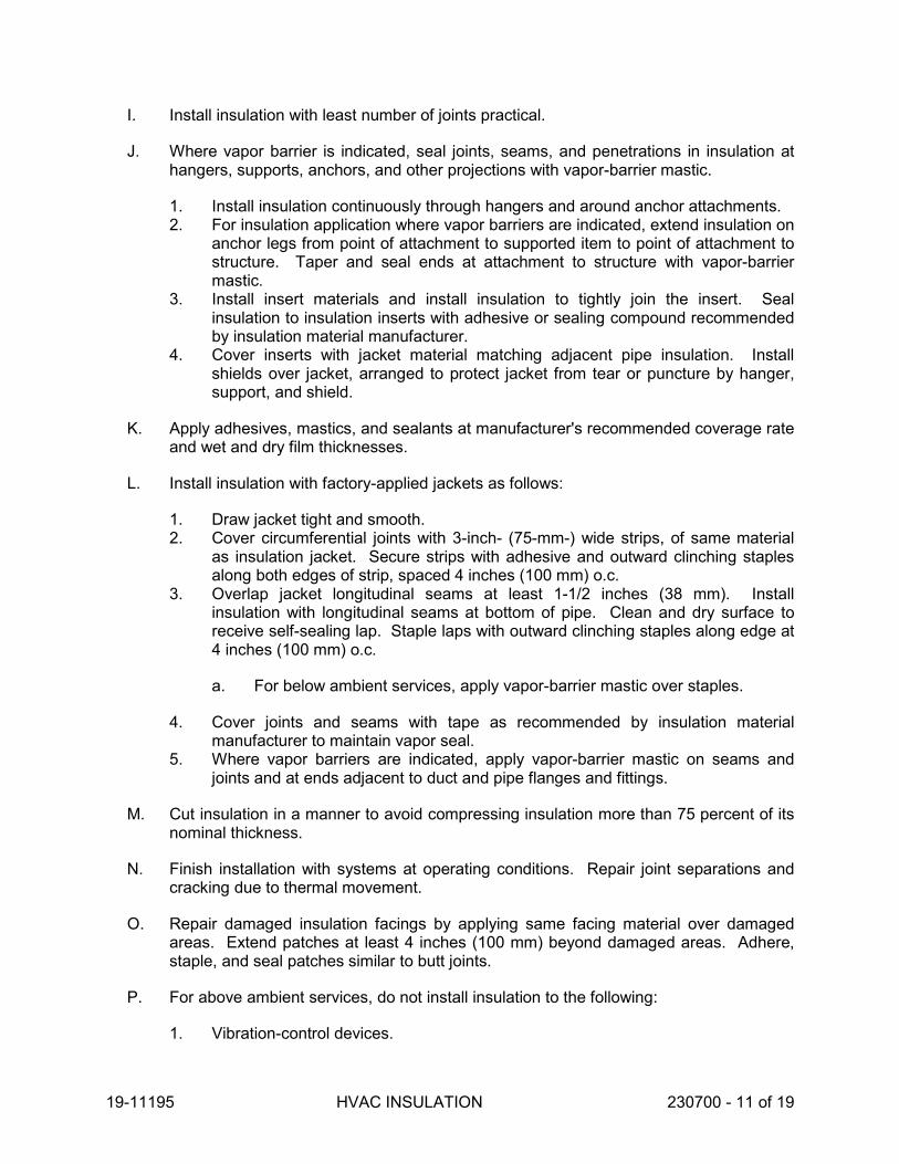
19-11195 HVAC INSULATION 230700 - 11 of 19
I. Install insulation with least number of joints practical.
J. Where vapor barrier is indicated, seal joints, seams, and penetrations in insulation athangers, supports, anchors, and other projections with vapor-barrier mastic.
1. Install insulation continuously through hangers and around anchor attachments.2. For insulation application where vapor barriers are indicated, extend insulation on
anchor legs from point of attachment to supported item to point of attachment tostructure. Taper and seal ends at attachment to structure with vapor-barriermastic.
3. Install insert materials and install insulation to tightly join the insert. Sealinsulation to insulation inserts with adhesive or sealing compound recommendedby insulation material manufacturer.
4. Cover inserts with jacket material matching adjacent pipe insulation. Installshields over jacket, arranged to protect jacket from tear or puncture by hanger,support, and shield.
K. Apply adhesives, mastics, and sealants at manufacturer's recommended coverage rateand wet and dry film thicknesses.
L. Install insulation with factory-applied jackets as follows:
1. Draw jacket tight and smooth.2. Cover circumferential joints with 3-inch- (75-mm-) wide strips, of same material
as insulation jacket. Secure strips with adhesive and outward clinching staplesalong both edges of strip, spaced 4 inches (100 mm) o.c.
3. Overlap jacket longitudinal seams at least 1-1/2 inches (38 mm). Installinsulation with longitudinal seams at bottom of pipe. Clean and dry surface toreceive self-sealing lap. Staple laps with outward clinching staples along edge at4 inches (100 mm) o.c.
a. For below ambient services, apply vapor-barrier mastic over staples.
4. Cover joints and seams with tape as recommended by insulation materialmanufacturer to maintain vapor seal.
5. Where vapor barriers are indicated, apply vapor-barrier mastic on seams andjoints and at ends adjacent to duct and pipe flanges and fittings.
M. Cut insulation in a manner to avoid compressing insulation more than 75 percent of itsnominal thickness.
N. Finish installation with systems at operating conditions. Repair joint separations andcracking due to thermal movement.
O. Repair damaged insulation facings by applying same facing material over damagedareas. Extend patches at least 4 inches (100 mm) beyond damaged areas. Adhere,staple, and seal patches similar to butt joints.
P. For above ambient services, do not install insulation to the following:
1. Vibration-control devices.

19-11195 HVAC INSULATION 230700 - 12 of 19
2. Testing agency labels and stamps. 3. Nameplates and data plates. 4. Manholes. 5. Handholes. 6. Cleanouts.
3.3 PENETRATIONS
A. Insulation Installation at Roof Penetrations: Install insulation continuously through roof penetrations.
1. Seal penetrations with flashing sealant. 2. For applications requiring only indoor insulation, terminate insulation above roof
surface and seal with joint sealant. For applications requiring indoor and outdoor insulation, install insulation for outdoor applications tightly joined to indoor insulation ends. Seal joint with joint sealant.
3. Extend jacket of outdoor insulation outside roof flashing at least 2 inches (50 mm) below top of roof flashing.
4. Seal jacket to roof flashing with flashing sealant.
B. Insulation Installation at Aboveground Exterior Wall Penetrations: Install insulation continuously through wall penetrations.
1. Seal penetrations with flashing sealant. 2. For applications requiring only indoor insulation, terminate insulation inside wall
surface and seal with joint sealant. For applications requiring indoor and outdoor insulation, install insulation for outdoor applications tightly joined to indoor insulation ends. Seal joint with joint sealant.
3. Extend jacket of outdoor insulation outside wall flashing and overlap wall flashing at least 2 inches (50 mm).
4. Seal jacket to wall flashing with flashing sealant.
C. Insulation Installation at Interior Wall and Partition Penetrations (That Are Not Fire Rated): Install insulation continuously through walls and partitions.
D. Insulation Installation at Fire-Rated Wall and Partition Penetrations: Install insulation continuously through penetrations of fire-rated walls and partitions. Terminate insulation at fire damper sleeves for fire-rated wall and partition penetrations. Externally insulate damper sleeves to match adjacent insulation and overlap duct insulation at least 2 inches (50 mm).
1. Comply with requirements in Division 07 Section "Penetration Firestopping"irestopping and fire-resistive joint sealers.
E. Insulation Installation at Floor Penetrations:
1. Duct: Install insulation continuously through floor penetrations that are not fire rated. For penetrations through fire-rated assemblies, terminate insulation at fire damper sleeves and externally insulate damper sleeve beyond floor to match

19-11195 HVAC INSULATION 230700 - 13 of 19
adjacent duct insulation. Overlap damper sleeve and duct insulation at least 2 inches (50 mm).
2. Pipe: Install insulation continuously through floor penetrations. 3. Seal penetrations through fire-rated assemblies. Comply with requirements in
Division 07 Section "Penetration Firestopping."
3.4 GENERAL PIPE INSULATION INSTALLATION
A. Requirements in this article generally apply to all insulation materials except where more specific requirements are specified in various pipe insulation material installation articles.
B. Insulation Installation on Fittings, Valves, Strainers, Flanges, and Unions:
1. Install insulation over fittings, valves, strainers, flanges, unions, and other specialties with continuous thermal and vapor-retarder integrity, unless otherwise indicated.
2. Insulate pipe elbows using preformed fitting insulation or mitered fittings made from same material and density as adjacent pipe insulation. Each piece shall be butted tightly against adjoining piece and bonded with adhesive. Fill joints, seams, voids, and irregular surfaces with insulating cement finished to a smooth, hard, and uniform contour that is uniform with adjoining pipe insulation.
3. Insulate tee fittings with preformed fitting insulation or sectional pipe insulation of same material and thickness as used for adjacent pipe. Cut sectional pipe insulation to fit. Butt each section closely to the next and hold in place with tie wire. Bond pieces with adhesive.
4. Insulate valves using preformed fitting insulation or sectional pipe insulation of same material, density, and thickness as used for adjacent pipe. Overlap adjoining pipe insulation by not less than two times the thickness of pipe insulation, or one pipe diameter, whichever is thicker. For valves, insulate up to and including the bonnets, valve stuffing-box studs, bolts, and nuts. Fill joints, seams, and irregular surfaces with insulating cement.
5. Insulate strainers using preformed fitting insulation or sectional pipe insulation of same material, density, and thickness as used for adjacent pipe. Overlap adjoining pipe insulation by not less than two times the thickness of pipe insulation, or one pipe diameter, whichever is thicker. Fill joints, seams, and irregular surfaces with insulating cement. Insulate strainers so strainer basket flange or plug can be easily removed and replaced without damaging the insulation and jacket. Provide a removable reusable insulation cover. For below ambient services, provide a design that maintains vapor barrier.
6. Insulate flanges and unions using a section of oversized preformed pipe insulation. Overlap adjoining pipe insulation by not less than two times the thickness of pipe insulation, or one pipe diameter, whichever is thicker.
7. Cover segmented insulated surfaces with a layer of finishing cement and coat with a mastic. Install vapor-barrier mastic for below ambient services and a breather mastic for above ambient services. Reinforce the mastic with fabric-reinforcing mesh. Trowel the mastic to a smooth and well-shaped contour.
8. For services not specified to receive a field-applied jacket except for flexible elastomeric and polyolefin, install fitted PVC cover over elbows, tees, strainers,

19-11195 HVAC INSULATION 230700 - 14 of 19
valves, flanges, and unions. Terminate ends with PVC end caps. Tape PVC covers to adjoining insulation facing using PVC tape.
9. Stencil or label the outside insulation jacket of each union with the word"UNION." Match size and color of pipe labels.
C. Insulate instrument connections for thermometers, pressure gages, pressuretemperature taps, test connections, flow meters, sensors, switches, and transmitters oninsulated pipes, vessels, and equipment. Shape insulation at these connections bytapering it to and around the connection with insulating cement and finish with finishingcement, mastic, and flashing sealant.
D. Install removable insulation covers at locations indicated. Installation shall conform tothe following:
1. Make removable flange and union insulation from sectional pipe insulation ofsame thickness as that on adjoining pipe. Install same insulation jacket asadjoining pipe insulation.
2. When flange and union covers are made from sectional pipe insulation, extendinsulation from flanges or union long at least two times the insulation thicknessover adjacent pipe insulation on each side of flange or union. Secure flangecover in place with stainless-steel or aluminum bands. Select band materialcompatible with insulation and jacket.
3. Construct removable valve insulation covers in same manner as for flangesexcept divide the two-part section on the vertical center line of valve body.
4. When covers are made from block insulation, make two halves, each consistingof mitered blocks wired to stainless-steel fabric. Secure this wire frame, with itsattached insulation, to flanges with tie wire. Extend insulation at least 2 inches(50 mm) over adjacent pipe insulation on each side of valve. Fill space betweenflange or union cover and pipe insulation with insulating cement. Finish coverassembly with insulating cement applied in two coats. After first coat is dry,apply and trowel second coat to a smooth finish.
5. Unless a PVC jacket is indicated in field-applied jacket schedules, finish exposedsurfaces with a metal jacket.
3.5 FLEXIBLE ELASTOMERIC INSULATION INSTALLATION
A. Seal longitudinal seams and end joints with manufacturer's recommended adhesive toeliminate openings in insulation that allow passage of air to surface being insulated.
B. Insulation Installation on Pipe Flanges:
1. Install pipe insulation to outer diameter of pipe flange.2. Make width of insulation section same as overall width of flange and bolts, plus
twice the thickness of pipe insulation.3. Fill voids between inner circumference of flange insulation and outer
circumference of adjacent straight pipe segments with cut sections of sheetinsulation of same thickness as pipe insulation.
4. Secure insulation to flanges and seal seams with manufacturer's recommendedadhesive to eliminate openings in insulation that allow passage of air to surfacebeing insulated.

19-11195 HVAC INSULATION 230700 - 15 of 19
C. Insulation Installation on Pipe Fittings and Elbows:
1. Install mitered sections of pipe insulation. 2. Secure insulation materials and seal seams with manufacturer's recommended
adhesive to eliminate openings in insulation that allow passage of air to surface being insulated.
D. Insulation Installation on Valves and Pipe Specialties:
1. Install preformed valve covers manufactured of same material as pipe insulation when available.
2. When preformed valve covers are not available, install cut sections of pipe and sheet insulation to valve body. Arrange insulation to permit access to packing and to allow valve operation without disturbing insulation.
3. Install insulation to flanges as specified for flange insulation application. 4. Secure insulation to valves and specialties and seal seams with manufacturer's
recommended adhesive to eliminate openings in insulation that allow passage of air to surface being insulated.
3.6 MINERAL-FIBER INSULATION INSTALLATION
A. Blanket Insulation Installation on Ducts and Plenums: Secure with adhesive and insulation pins.
1. Apply adhesives according to manufacturer's recommended coverage rates per unit area, for 100 percent coverage of duct and plenum surfaces.
2. Apply adhesive to entire circumference of ducts and to all surfaces of fittings and transitions.
3. Install either capacitor-discharge-weld pins and speed washers or cupped-head, capacitor-discharge-weld pins on sides and bottom of horizontal ducts and sides of vertical ducts as follows:
a. On duct sides with dimensions 18 inches (450 mm) and smaller, place pins along longitudinal centerline of duct. Space 3 inches (75 mm) maximum from insulation end joints, and 16 inches (400 mm) o.c.
b. On duct sides with dimensions larger than 18 inches (450 mm), place pins 16 inches (400 mm) o.c. each way, and 3 inches (75 mm) maximum from insulation joints. Install additional pins to hold insulation tightly against surface at cross bracing.
c. Pins may be omitted from top surface of horizontal, rectangular ducts and plenums.
d. Do not overcompress insulation during installation. e. Impale insulation over pins and attach speed washers. f. Cut excess portion of pins extending beyond speed washers or bend
parallel with insulation surface. Cover exposed pins and washers with tape matching insulation facing.
4. For ducts and plenums with surface temperatures below ambient, install a continuous unbroken vapor barrier. Create a facing lap for longitudinal seams and end joints with insulation by removing 2 inches (50 mm) from 1 edge and 1

19-11195 HVAC INSULATION 230700 - 16 of 19
end of insulation segment. Secure laps to adjacent insulation section with 1/2-inch (13-mm) outward-clinching staples, 1 inch (25 mm) o.c. Install vapor barrier consisting of factory- or field-applied jacket, adhesive, vapor-barrier mastic, and sealant at joints, seams, and protrusions.
a. Repair punctures, tears, and penetrations with tape or mastic to maintain vapor-barrier seal.
b. Install vapor stops for ductwork and plenums operating below 50 deg F (10 deg C) at 18-foot (5.5-m) intervals. Vapor stops shall consist of vapor-barrier mastic applied in a Z-shaped pattern over insulation face, along butt end of insulation, and over the surface. Cover insulation face and surface to be insulated a width equal to 2 times the insulation thickness but not less than 3 inches (75 mm).
5. Overlap unfaced blankets a minimum of 2 inches (50 mm) on longitudinal seams and end joints. At end joints, secure with steel bands spaced a maximum of 18 inches (450 mm) o.c.
6. Install insulation on rectangular duct elbows and transitions with a full insulation section for each surface. Install insulation on round and flat-oval duct elbows with individually mitered gores cut to fit the elbow.
7. Insulate duct stiffeners, hangers, and flanges that protrude beyond insulation surface with 6-inch- (150-mm-) wide strips of same material used to insulate duct. Secure on alternating sides of stiffener, hanger, and flange with pins spaced 6 inches (150 mm) o.c.
B. Board Insulation Installation on Ducts and Plenums: Secure with adhesive and insulation pins.
1. Apply adhesives according to manufacturer's recommended coverage rates per unit area, for 100 percent coverage of duct and plenum surfaces.
2. Apply adhesive to entire circumference of ducts and to all surfaces of fittings and transitions.
3. Install either capacitor-discharge-weld pins and speed washers or cupped-head, capacitor-discharge-weld pins on sides and bottom of horizontal ducts and sides of vertical ducts as follows:
a. On duct sides with dimensions 18 inches (450 mm) and smaller, place pins along longitudinal centerline of duct. Space 3 inches (75 mm) maximum from insulation end joints, and 16 inches (400 mm) o.c.
b. On duct sides with dimensions larger than 18 inches (450 mm), space pins 16 inches (400 mm) o.c. each way, and 3 inches (75 mm) maximum from insulation joints. Install additional pins to hold insulation tightly against surface at cross bracing.
c. Pins may be omitted from top surface of horizontal, rectangular ducts and plenums.
d. Do not overcompress insulation during installation. e. Cut excess portion of pins extending beyond speed washers or bend
parallel with insulation surface. Cover exposed pins and washers with tape matching insulation facing.

19-11195 HVAC INSULATION 230700 - 17 of 19
4. For ducts and plenums with surface temperatures below ambient, install a continuous unbroken vapor barrier. Create a facing lap for longitudinal seams and end joints with insulation by removing 2 inches (50 mm) from 1 edge and 1 end of insulation segment. Secure laps to adjacent insulation section with 1/2-inch (13-mm) outward-clinching staples, 1 inch (25 mm) o.c. Install vapor barrier consisting of factory- or field-applied jacket, adhesive, vapor-barrier mastic, and sealant at joints, seams, and protrusions.
a. Repair punctures, tears, and penetrations with tape or mastic to maintain vapor-barrier seal.
b. Install vapor stops for ductwork and plenums operating below 50 deg F (10 deg C) at 18-foot (5.5-m) intervals. Vapor stops shall consist of vapor-barrier mastic applied in a Z-shaped pattern over insulation face, along butt end of insulation, and over the surface. Cover insulation face and surface to be insulated a width equal to 2 times the insulation thickness but not less than 3 inches (75 mm).
5. Install insulation on rectangular duct elbows and transitions with a full insulation section for each surface. Groove and score insulation to fit as closely as possible to outside and inside radius of elbows. Install insulation on round and flat-oval duct elbows with individually mitered gores cut to fit the elbow.
6. Insulate duct stiffeners, hangers, and flanges that protrude beyond insulation surface with 6-inch- (150-mm-) wide strips of same material used to insulate duct. Secure on alternating sides of stiffener, hanger, and flange with pins spaced 6 inches (150 mm) o.c.
3.7 FIELD-APPLIED JACKET INSTALLATION
A. Where PVC jackets are indicated, install with 1-inch (25-mm) overlap at longitudinal seams and end joints; for horizontal applications, install with longitudinal seams along top and bottom of tanks and vessels. Seal with manufacturer's recommended adhesive.
1. Apply two continuous beads of adhesive to seams and joints, one bead under lap and the finish bead along seam and joint edge.
B. Where metal jackets are indicated, install with 2-inch (50-mm) overlap at longitudinal seams and end joints. Overlap longitudinal seams arranged to shed water. Seal end joints with weatherproof sealant recommended by insulation manufacturer. Secure jacket with stainless-steel bands 12 inches (300 mm) o.c. and at end joints.
3.8 FIRE-RATED INSULATION SYSTEM INSTALLATION
A. Where fire-rated insulation system is indicated, secure system to ducts and duct hangers and supports to maintain a continuous fire rating.
B. Insulate duct access panels and doors to achieve same fire rating as duct.

19-11195 HVAC INSULATION 230700 - 18 of 19
C. Install firestopping at penetrations through fire-rated assemblies. Fire-stop systems are specified in Division 07 Section "Penetration Firestopping."
3.9 DUCT INSULATION SCHEDULE, GENERAL
A. Plenums and Ducts Requiring Insulation:
1. Indoor, concealed supply and outdoor air. 2. Indoor, concealed return located in nonconditioned space. 3. Indoor, concealed, Type I, commercial, kitchen hood exhaust. 4. Indoor, exposed, Type I, commercial, kitchen hood exhaust. 5. Outdoor, concealed supply and return. 6. Outdoor, exposed supply and return.
B. Items Not Insulated:
1. Metal ducts with duct liner of sufficient thickness to comply with energy code and ASHRAE/IESNA 90.1.
2. Factory-insulated flexible ducts. 3. Factory-insulated plenums and casings. 4. Flexible connectors. 5. Vibration-control devices. 6. Factory-insulated access panels and doors.
3.10 INDOOR DUCT AND PLENUM INSULATION SCHEDULE
A. Concealed, Supply-Air Duct and Plenum Insulation: Mineral-fiber blanket, 1-1/2 inches (38 mm) thick and 0.75-lb/cu. ft. (12-kg/cu. m) nominal density (R-4.2 minimum).
B. Concealed, Return-Air Duct and Plenum Insulation: Mineral-fiber blanket, 1-1/2 inches (38 mm) thick and 0.75-lb/cu. ft. (12-kg/cu. m) nominal density (R-4.2 minimum).
C. Concealed, Outdoor-Air Duct and Plenum Insulation: Mineral-fiber blanket, 1-1/2 inches (38 mm) thick and 0.75-lb/cu. ft. (12-kg/cu. m) nominal density (R-4.2 minimum).
D. Exposed, Supply-Air Duct Insulation: Mineral-Fiber Board 1 inch thick and minimum 2-lb/cu. ft. nominal density.
3.11 PIPING INSULATION SCHEDULE, GENERAL
A. Acceptable preformed pipe and tubular insulation materials and thicknesses are identified for each piping system and pipe size range. If more than one material is listed for a piping system, selection from materials listed is Contractor's option.
B. Items Not Insulated: Unless otherwise indicated, do not install insulation on the following:
1. Drainage piping located in crawl spaces.

19-11195 HVAC INSULATION 230700 - 19 of 19
2. Underground piping. 3. Chrome-plated pipes and fittings unless there is a potential for personnel injury.
3.12 INDOOR PIPING INSULATION SCHEDULE
A. Refrigerant Suction and Hot-Gas Piping: Flexible elastomeric, 1 inch (25 mm) thick.
3.13 OUTDOOR, ABOVEGROUND PIPING INSULATION SCHEDULE
A. Refrigerant Suction and Hot-Gas Piping: Insulation shall be one of the following:
1. Flexible Elastomeric: 1-1/2 inches (38 mm) thick.
3.14 INDOOR, FIELD-APPLIED JACKET SCHEDULE
A. Install jacket over insulation material. For insulation with factory-applied jacket, install the field-applied jacket over the factory-applied jacket.
B. If more than one material is listed, selection from materials listed is Contractor's option.
C. Ducts and Plenums, Exposed:
1. None.
D. Piping, Exposed:
1. PVC: 20 mils (0.5 mm) thick.
3.15 OUTDOOR, FIELD-APPLIED JACKET SCHEDULE
A. Install jacket over insulation material. For insulation with factory-applied jacket, install the field-applied jacket over the factory-applied jacket.
B. If more than one material is listed, selection from materials listed is Contractor's option.
C. Ducts and Plenums, Concealed:
1. None.
D. Piping, Exposed:
1. Aluminum, corrugated: 0.024 inches thick.
END OF SECTION


19-11195 COMMISSIONING OF HVAC 230800 - 1 of 5
SECTION 230800 COMMISSIONING OF HVAC
PART 1 - GENERAL
1.1 RELATED DOCUMENTS
A. Drawings and general provisions of the Contract, including General and Supplementary Conditions and other Division 01 Specification Sections, apply to this Section.
1.2 SUMMARY
A. Section includes commissioning process requirements for HVAC&R systems, assemblies, and equipment.
B. Related Sections:
1. Division 01 Section "General Commissioning Requirements" for general commissioning process requirements.
1.3 DEFINITIONS
A. Commissioning Plan: A document that outlines the organization, schedule, allocation of resources, and documentation requirements of the commissioning process.
B. CxA: Commissioning Authority.
C. HVAC&R: Heating, Ventilating, Air Conditioning, and Refrigeration.
D. Systems, Subsystems, Equipment, and Components: Where these terms are used together or separately, they shall mean "as-built" systems, subsystems, equipment, and components.
1.4 ALLOWANCES
A. Labor, instrumentation, tools, and equipment costs for technicians for the performance of commissioning testing are covered by the "Schedule of Allowances" Article in Division 01 Section "Allowances."
1.5 CONTRACTOR'S RESPONSIBILITIES
A. Perform commissioning tests at the direction of the CxA.
B. Attend construction phase controls coordination meeting.

19-11195 COMMISSIONING OF HVAC 230800 - 2 of 5
C. Attend testing, adjusting, and balancing review and coordination meeting.
D. Participate in HVAC&R systems, assemblies, equipment, and component maintenance orientation and inspection as directed by the CxA.
E. Provide information requested by the CxA for final commissioning documentation.
F. Provide measuring instruments and logging devices to record test data, and provide data acquisition equipment to record data for the complete range of testing for the required test period.
1.6 CxA'S RESPONSIBILITIES
A. Provide Project-specific construction checklists and commissioning process test procedures for actual HVAC&R systems, assemblies, equipment, and components to be furnished and installed as part of the construction contract.
B. Direct commissioning testing.
C. Verify testing, adjusting, and balancing of Work are complete.
D. Provide test data, inspection reports, and certificates in Systems Manual.
1.7 COMMISSIONING DOCUMENTATION
A. Provide the following information to the CxA for inclusion in the commissioning plan:
1. Plan for delivery and review of submittals, systems manuals, and other documents and reports.
2. Identification of installed systems, assemblies, equipment, and components including design changes that occurred during the construction phase.
3. Process and schedule for completing construction checklists and manufacturer's prestart and startup checklists for HVAC&R systems, assemblies, equipment, and components to be verified and tested.
4. Certificate of completion certifying that installation, prestart checks, and startup procedures have been completed.
5. Certificate of readiness certifying that HVAC&R systems, subsystems, equipment, and associated controls are ready for testing.
6. Test and inspection reports and certificates. 7. Corrective action documents. 8. Verification of testing, adjusting, and balancing reports.
1.8 SUBMITTALS
A. Certificates of readiness.
B. Certificates of completion of installation, prestart, and startup activities.

19-11195 COMMISSIONING OF HVAC 230800 - 3 of 5
PART 2 - PRODUCTS (Not Used)
PART 3 - EXECUTION
3.1 TESTING PREPARATION
A. Certify that HVAC&R systems, subsystems, and equipment have been installed, calibrated, and started and are operating according to the Contract Documents.
B. Certify that HVAC&R instrumentation and control systems have been completed and calibrated, that they are operating according to the Contract Documents, and that pretest set points have been recorded.
C. Certify that testing, adjusting, and balancing procedures have been completed and that testing, adjusting, and balancing reports have been submitted, discrepancies corrected, and corrective work approved.
D. Set systems, subsystems, and equipment into operating mode to be tested (e.g., normal shutdown, normal auto position, normal manual position, unoccupied cycle, emergency power, and alarm conditions).
E. Inspect and verify the position of each device and interlock identified on checklists.
F. Check safety cutouts, alarms, and interlocks with smoke control and life-safety systems during each mode of operation.
G. Testing Instrumentation: Install measuring instruments and logging devices to record test data as directed by the CxA.
3.2 Testing AND BALANCING VERIFICATION
A. Prior to performance of testing and balancing Work, provide copies of reports, sample forms, checklists, and certificates to the CxA.
B. Notify the CxA at least 10 days in advance of testing and balancing Work, and provide access for the CxA to witness testing and balancing Work.
C. Provide technicians, instrumentation, and tools to verify testing and balancing of HVAC&R systems at the direction of the CxA.
1. The CxA will notify testing and balancing Contractor 10 days in advance of the date of field verification. Notice will not include data points to be verified.
2. The testing and balancing Contractor shall use the same instruments (by model and serial number) that were used when original data were collected.
3. Failure of an item includes, other than sound, a deviation of more than 10 percent. Failure of more than 10 percent of selected items shall result in rejection of final testing, adjusting, and balancing report. For sound pressure readings, a deviation of 3 dB shall result in rejection of final testing. Variations in background noise must be considered.

19-11195 COMMISSIONING OF HVAC 230800 - 4 of 5
4. Remedy the deficiency and notify the CxA so verification of failed portions can be performed.
3.3 GENERAL TESTING REQUIREMENTS
A. Provide technicians, instrumentation, and tools to perform commissioning test at the direction of the CxA.
B. Scope of HVAC&R testing shall include entire HVAC&R installation, from central equipment for heat generation and refrigeration through distribution systems to each conditioned space. Testing shall include measuring capacities and effectiveness of operational and control functions.
C. Test all operating modes, interlocks, control responses, and responses to abnormal or emergency conditions, and verify proper response of building automation system controllers and sensors.
D. The CxA along with the HVAC&R Contractor, testing and balancing Contractor, and HVAC&R Instrumentation and Control Contractor shall prepare detailed testing plans, procedures, and checklists for HVAC&R systems, subsystems, and equipment.
E. Tests will be performed using design conditions whenever possible.
F. Simulated conditions may need to be imposed using an artificial load when it is not practical to test under design conditions. Before simulating conditions, calibrate testing instruments. Provide equipment to simulate loads. Set simulated conditions as directed by the CxA and document simulated conditions and methods of simulation. After tests, return settings to normal operating conditions.
G. The CxA may direct that set points be altered when simulating conditions is not practical.
H. The CxA may direct that sensor values be altered with a signal generator when design or simulating conditions and altering set points are not practical.
I. If tests cannot be completed because of a deficiency outside the scope of the HVAC&R system, document the deficiency and report it to the Owner. After deficiencies are resolved, reschedule tests.
J. If the testing plan indicates specific seasonal testing, complete appropriate initial performance tests and documentation and schedule seasonal tests.
3.4 HVAC&R SYSTEMS, SUBSYSTEMS, AND EQUIPMENT TESTING PROCEDURES
A. HVAC&R Instrumentation and Control System Testing: Field testing plans and testing requirements are specified in Division 23 Sections "Instrumentation and Control for HVAC" and "Sequence of Operations for HVAC Controls." Assist the CxA with preparation of testing plans.

19-11195 COMMISSIONING OF HVAC 230800 - 5 of 5
B. Refrigeration System Testing: Provide technicians, instrumentation, tools, andequipment to test performance of chillers, cooling towers, refrigerant compressors andcondensers, heat pumps, and other refrigeration systems. The CxA shall determinethe sequence of testing and testing procedures for each equipment item and pipesection to be tested.
C. HVAC&R Distribution System Testing: Provide technicians, instrumentation, tools, andequipment to test performance of air, steam, and hydronic distribution systems; specialexhaust; and other distribution systems, including HVAC&R terminal equipment andunitary equipment.
END OF SECTION


19-11195 BUILDING AUTOMATION SYSTEM 230900 - 1 of 64
SECTION 230900 BUILDING AUTOMATION SYSTEM
PART 1 - GENERAL
1.1 SUMMARY
A. This Section includes control equipment and installation for HVAC systems and components, including control components for terminal heating and cooling units not supplied with factory-furnished controls.
B. The control system shall be tie-in into the County’s existing Siemens Building Automation System located at the county engineering office and all controllers and software shall match existing or be the latest version of existing.
C. The entire control system shall be BACnet/IP. BACnet MSTP, ARCNET, and LON are not acceptable. All primary and secondary controllers shall communicate using BACnet/IP. Proprietary protocols such as Niagara / Fox are not acceptable.
D. This Section includes an Energy Reporting, Automated Fault Detection and Diagnostics, and Data Analytics software package.
E. See "Sequences of Operation" for requirements that relate to this Section.
1.2 RELATED DOCUMENTS
A. Drawings and general provisions of the Contract, including General and Supplementary Conditions and Division 01 Specification Sections, apply to this Section.
1.3 ABBREVIATIONS
A. AAC: Advanced Application Controller B. AHU: Air Handling Unit. C. ALN: Automation Level Network D. ASC: Application Specific Controller E. ASHRAE: American Society of Heating Refrigerating and Air-Conditioning Engineers F. BAS: Building Automation System G. BC: Building Controller H. BIBB: BACnet Interoperability Building Blocks I. BIM: Building Information Modeling J. BMS: Building Management System. K. CFM: Cubic Feet per Minute. L. DCIM: Data Center Infrastructure Management M. DCV: Demand Controlled Ventilation N. DDC: Direct digital controls O. EIA: Electronics Industries Alliance P. EMI: Electro-Magnetic Interference

19-11195 BUILDING AUTOMATION SYSTEM 230900 - 2 of 64
Q. EP: Electric-to-Pneumatic R. EPMS: Electrical Power Monitoring System S. FAS: Fire Alarm System. T. FLN: Floor Level Network U. FCU: Fan Coil Unit V. HMI: Human Machine Interface W. HVAC: Heating, Ventilating and Air Conditioning. X. IEEE: Institute of Electrical and Electronic Engineers Y. I/O: Input/Output Z. IP: Internet Protocol AA. IT: Information Technology BB. LAN: Local area network. CC. LCD: Liquid Crystal Display DD. LED: Light Emitting Diode EE. MER: Mechanical Equipment Room. FF. MLN: Management Level Network GG. MS/TP: Master-slave/token-passing. HH. NEMA: National Electric Manufacturers’ Association II. NFPA: National Fire Protection Association JJ. OEM: Operator Equipment Manufacturer KK. PC: Personal Computer LL. PICS: Protocol Implementation Conformance Statement MM. PID: Proportional Integral Derivative. NN. POT: Portable Operators Terminal. OO. RAM: Random Access Memory PP. RFI: Radio Frequency Interference QQ. RTD: Resistance Temperature Device RR. SNMP: Simple Network Management Protocol SS. TAB: Testing and Balancing TT. TCP: Transfer Control Protocol UU. UDP: User Datagram Protocol VV. UL: Underwriters Laboratories WW. UPS: Uninterruptable Power Supply XX. VAV: Variable Air Volume YY. VFD: Variable Frequency Drive. ZZ. WAN: Wide Area Network.
1.4 DEFINITIONS
A. BACnet: An industry standard data communication protocol for Building Automation and Control Networks. Refer to the latest version of AHSRAE standard 135.
B. Scope Terminology
1. Provide = Furnish equipment, engineer, program and install 2. Furnish = Furnish equipment, engineer and program 3. Mount = securely fasten or pipe 4. Install = mount and wire 5. Wire = wire only

19-11195 BUILDING AUTOMATION SYSTEM 230900 - 3 of 64
1.5 WORK INCLUDED
A. The BAS Contractor shall provide a complete and operational system that will perform the sequences of operation as described herein.
B. Furnish a complete distributed direct digital control system in accordance with this specification section. This includes all system controllers, logic controllers, and all input/output devices. Items of work included are as follows:
1. Provide a submittal that meets the requirements below for approval. 2. Coordinate installation schedule with the mechanical contractor and general
contractor. 3. Provide installation of all panels and devices unless otherwise stated. 4. Provide power for panels and control devices unless otherwise stated. 5. Provide all low voltage control wiring for the DDC system. 6. Provide miscellaneous control wiring for HVAC and related systems regardless of
voltage. 7. Provide engineering and technician labor to program and commission software for
each system and operator interface. Submit commissioning reports for approval. 8. Provide testing, demonstration and training as specified below.
C. The installation of the control system shall be performed under the direct supervision of the controls manufacturer with the shop drawings, flow diagrams, bill of materials, component designation, or identification number and sequence of operation all bearing the name of the manufacturer.
D. Provide Energy Reporting and Data Analytics software package. Software package shall include fault detection and diagnostics, analytics, carbon foot printing, energy star benchmarking tools, supply side cost optimization modules. Software package shall include capability for integration into CMMS for real time graphical mapping of faults detected with equipment.
1.6 SUBMITTALS
A. Provide submittals for fast track items that need to be approved and released to meet the schedule of the project. Provide submittals for the following items separately upon request:
1. Valve schedule and product data 2. Damper schedule and product data 3. Mounting and wiring diagrams for factory-installed control components 4. Thermostat locations
B. Provide a complete submittal with all controls system information for approval before construction starts. Include the following:
1. Schematic flow diagrams showing fans, pumps, coils, dampers, valves, and control devices.
2. Wiring Diagrams: Power, signal, and control wiring. Detail the wiring of the control devices and the panels. Show point-to-point wiring from field devices to the control

19-11195 BUILDING AUTOMATION SYSTEM 230900 - 4 of 64
panel. Show point-to-point wiring of hardwired interlocks. Show a ladder diagram or schematic of wiring internal to the panels, including numbered terminals. Clearly designate wiring that is done at a factory, at a panel shop or in the field.
3. Details of control panel faces, including sizes, controls, instruments, and labeling. 4. Schedule of dampers and actuators including size, leakage, and flow
characteristics. If dampers are furnished by other, submit a damper actuator schedule coordinating actuator sizes with the damper schedule.
5. Schedule of valves including leakage and flow characteristics. 6. Written description of the Sequence of Operations. 7. Network riser diagram showing wiring types, network protocols, locations of floor
penetrations and number of control panels. Label control panels with network addresses and BACnet device instance numbers. Show all routers, switches, hubs and repeaters.
8. Point list for each system controller including both inputs and outputs (I/O), point numbers, controlled device associated with each I/O point, and location of I/O device.
9. Starter and variable frequency drive wiring details of all automatically controlled motors.
10. Reduced size floor plan drawings showing locations of control panels, thermostats and any devices mounted in occupied space.
11. Product Data: Include manufacturer's technical literature for each control device indicated, labeled with setting or adjustable range of control. Indicate dimensions, capacities, performance characteristics, electrical characteristics, finishes for materials, and installation and startup instructions for each type of product indicated. Submit a write-up of the application software that will be used on the operator workstation including revision level, functionality and software applications required to meet the specifications.
12. Submit BACnet Protocol Implementation Conformance Statements (PICS) for all direct digital controllers, software and other system components that will communicate on the BAS utilizing BACnet.
C. Submit a description of the application software that will be used on the operator workstation including revision level, functionality and software applications required to meet the specifications.
D. Submit blank field check-out and commissioning test reports, customized for each panel or system, which will be filled out by the technician during start-up.
E. Operation and Maintenance Data: In addition to items specified in Division 1, include the following:
1. Product data with installation details, maintenance instructions and lists of spare parts for each type of control device.
2. Keyboard illustrations and step-by-step procedures indexed for each operator function.
3. Inspection period, cleaning methods, cleaning materials recommended and calibration tolerances.
4. Calibration records and list of set points.
1.7 PROJECT RECORD DOCUMENTS

19-11195 BUILDING AUTOMATION SYSTEM 230900 - 5 of 64
A. Project Record Documents: Submit three (3) copies of record (as-built) documents upon completion of installation. Submittal shall consist of:
1. Project Record Drawings. As-built versions of the submittal shop drawings provided as AutoCAD compatible files in electronic format and as 11 x 17 inch prints.
2. Testing and Commissioning Reports and Checklists. Completed versions of reports, checklists, and trend logs used to meet requirements in the Control System Demonstration and Acceptance section of this specification.
3. Operation and Maintenance (O & M) Manual.
a. As-built versions of the submittal product data. b. Names, addresses, and 24-hour telephone numbers of installing contractors
and service representatives for equipment and control systems. c. Operator’s Manual with procedures for operating control systems, logging on
and off, handling alarms, producing point reports, trending data, overriding computer control, and changing setpoints and variables.
d. Programming manual or set of manuals with description of programming language and of statements for algorithms and calculations used, of point database creation and modification, of program creation and modification, and of editor use.
e. Engineering, installation, and maintenance manual or set of manuals that explains how to design and install new points, panels, and other hardware; how to perform preventive maintenance and calibration; how to debug hardware problems; and how to repair or replace hardware.
f. Documentation of all programs created using custom programming language, including setpoints, tuning parameters, and object database.
g. Graphic files, programs, and database on electronic media. h. List of recommended spare parts with part numbers and suppliers. i. Complete original-issue documentation, installation, and maintenance
information for furnished third-party hardware, including computer equipment and sensors.
j. Complete original original-issue copies of furnished software, including operating systems, custom programming language, operator workstation software, and graphics software.
k. Licenses, guarantees, and warranty documents for equipment and systems.
B. Operating manual to serve as training and reference manual for all aspects of day-to-day operation of the system. As a minimum include the following:
1. Sequence of operation for automatic and manual operating modes for all building systems. The sequences shall cross-reference the system point names.
2. Description of manual override operation of all control points in system. 3. BMS system manufacturers complete operating manuals.
C. Provide maintenance manual to serve as training and reference manual for all aspects of day-to-day maintenance and major system repairs. As a minimum include the following:
1. Complete as-built installation drawings for each building system.

19-11195 BUILDING AUTOMATION SYSTEM 230900 - 6 of 64
2. Overall system electrical power supply schematic indicating source of electrical power for each system component. Indicate all battery backup provisions.
3. Photographs and/or drawings showing installation details and locations of equipment.
4. Routine preventive maintenance procedures, corrective diagnostics troubleshooting procedures, and calibration procedures.
5. Parts list with manufacturer's catalog numbers and ordering information. 6. Lists of ordinary and special tools, operating materials supplies and test equipment
recommended for operation and servicing. 7. Manufacturer's operation, set-up, maintenance and catalog literature for each
piece of equipment. 8. Maintenance and repair instructions. 9. Recommended spare parts.
D. Provide Programming Manual to serve as training and reference manual for all aspects of system programming. As a minimum include the following:
1. Complete programming manuals, and reference guides. 2. Details of any custom software packages and compilers supplied with system. 3. Information and access required for independent programming of system.
1.8 QUALITY ASSURANCE
A. Codes:
1. Perform all wiring in accordance with Division 26, NEC, local codes and Owner’s requirements.
2. Electrical Components, Devices, and Accessories: Listed and labeled as defined in NFPA 70, Article 100, by a testing agency acceptable to authorities having jurisdiction, and marked for intended use.
3. Comply with NFPA 90A, "Installation of Air Conditioning and Ventilation Systems." 4. Comply with ASHRAE 135-2010 BACnet: A Data Communication Protocol for
Building Automation and Control Networks. 5. Comply with ASHRAE 90.1-2007, 2010, 2013 Energy Standard for Buildings
Except Low-Rise Residential Buildings. 6. Comply with current version of the State of California’s Building Energy Efficiency
Standards for Residential and Non-Residential Buildings (Title 24). 7. All equipment shall be UL listed and approved and shall meet with all applicable
NFPA standards, including UL 916 - PAZX Energy Management Systems,
a. Provide written approvals and certifications after installation has been completed.
8. All electronic equipment shall conform to the requirements of FCC Regulation, Part 15, Governing Radio Frequency Electromagnetic Interference and be so labeled.
9. The manufacturer of the building automation system shall provide documentation supporting compliance with ISO-9002 (Model for Quality Assurance in Production, Installation, and Servicing) and ISO-140001 (The application of well-accepted business management principles to the environment). The intent of this specification requirement is to ensure that the products from the manufacturer are

19-11195 BUILDING AUTOMATION SYSTEM 230900 - 7 of 64
delivered through a Quality System and Framework that will assure consistency in the products delivered for this project.
B. Qualifications
1. Installing contractor shall be in the business of installing and servicing DDC controls for mechanical systems, temperature and ventilation control, environmental control, lighting control, access and security, life safety and energy management as their primary business.
2. Installer Qualifications: An experienced installer who is the authorized representative of the automatic control system manufacturer for both installation and maintenance of controls required for this Project.
3. Engineering, drafting, programming, and graphics generation shall be performed by the local branch engineers and technicians directly employed by the Building Automation System Contractor.
4. Supervision, checkout and commissioning of the system shall be by the local branch engineers and technicians directly employed by the Building Automation System Contractor. They shall perform commissioning and complete testing of the BAS system.
C. The BAS contractor shall have a branch office within 75 miles of the site and maintain a service organization consisting of factory trained service personnel and provide a list of ten (10) projects, similar in size and scope to this project, completed within the last five years.
D. Final determination of compliance with these specifications shall rest solely with the Engineer and Owner who will require proof of prior satisfactory performance.
E. All portions of the system must be designed, furnished, installed, commissioned and serviced by manufacturer approved, factory trained employees.
F. The system shall have a documented history of compatibility by design for a minimum of 15 years. Future compatibility shall be supported for no less than 10 years. Compatibility shall be defined as the ability for any existing control system component including but not limited to building controllers, advanced application controllers, application specific, personal operator workstations and portable operator's terminals, to be connected and directly communicate with any new BAS system equipment without bridges, routers or protocol converters.
1.9 DELIVERY, STORAGE, AND HANDLING
A. Factory-Mounted Components: Where control devices specified in this Section are indicated to be factory mounted on equipment, arrange for shipping of control devices to unit manufacturer.
B. Deliver, store, protect, and handle products to site under provisions of the contract Documents. Coordinate all site delivers with Construction project Manager.
C. Protect products from construction operations, dust, and debris, by storing materials inside, protected from weather in a conditioned space.

19-11195 BUILDING AUTOMATION SYSTEM 230900 - 8 of 64
1.10 COORDINATION
A. Coordinate IP drops, network connections, user interfaces, firewall, etc with Owner’s IT representative.
B. Coordinate location of thermostats, humidistats, panels, and other exposed control components with plans and room details before installation.
C. Coordinate equipment with Division 28 "Fire Alarm" to achieve compatibility with equipment that interfaces with that system.
D. Coordinate power for control units and operator workstation with electrical contractor.
E. Coordinate equipment with provider of starters and drives to achieve compatibility with motor starter control coils and VFD control wiring.
F. Coordinate scheduling with the mechanical contractor and general contractor. Submit a schedule for approval based upon the installation schedule of the mechanical equipment.
G. Coordinate installation of taps, valves, airflow stations, etc. with the mechanical contractor.
1.11 WARRANTY
A. Provide warranty per Division 23 Section “General Mechanical Requirements” and as supplemented in this section.
B. Warranty shall cover all costs for parts, labor, associated travel, and expenses for a period of 12 months from completion of system demonstration.
C. Hardware and software personnel supporting this warranty agreement shall provide on-site or off-site service in a timely manner after failure notification to the vendor. The maximum acceptable response time to provide this service at the site shall be 24 hours.
D. Warranty period shall include coverage and monitoring from a manufacture owned and operated remote digital Service Center.
1. Staffed 24/7. 2. Shall be able proactively identify system faults, determine root cause and provide
immediately system interrogation and response through client server connectivity (CRSP) connection.
3. Any fault or alarm not resolvable online shall include a maximum 4 hour on site response time from the BAS contractor.
E. During normal building occupied hours, failure of FDD system operation for that is critical for system operation shall be provided within 4 hours of notification from the Owner’s Representative.
F. This warranty shall apply equally to both hardware and software.
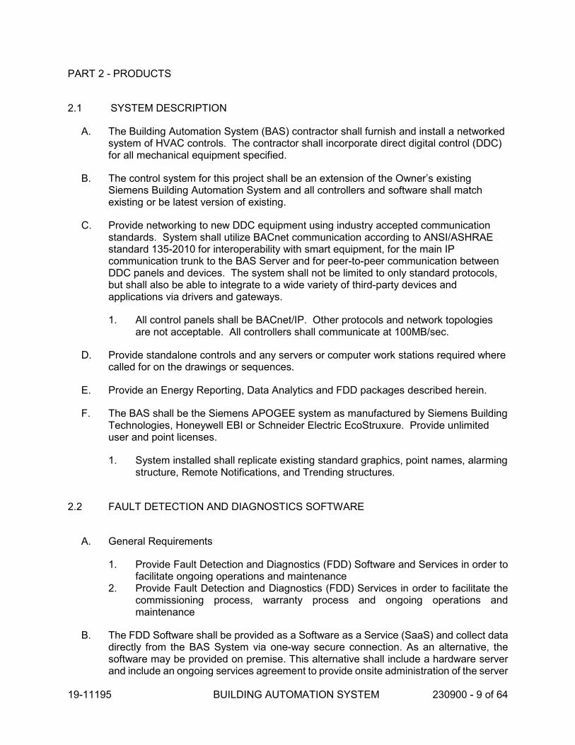
19-11195 BUILDING AUTOMATION SYSTEM 230900 - 9 of 64
PART 2 - PRODUCTS
2.1 SYSTEM DESCRIPTION
A. The Building Automation System (BAS) contractor shall furnish and install a networked system of HVAC controls. The contractor shall incorporate direct digital control (DDC) for all mechanical equipment specified.
B. The control system for this project shall be an extension of the Owner’s existing Siemens Building Automation System and all controllers and software shall match existing or be latest version of existing.
C. Provide networking to new DDC equipment using industry accepted communication standards. System shall utilize BACnet communication according to ANSI/ASHRAE standard 135-2010 for interoperability with smart equipment, for the main IP communication trunk to the BAS Server and for peer-to-peer communication between DDC panels and devices. The system shall not be limited to only standard protocols, but shall also be able to integrate to a wide variety of third-party devices and applications via drivers and gateways.
1. All control panels shall be BACnet/IP. Other protocols and network topologies are not acceptable. All controllers shall communicate at 100MB/sec.
D. Provide standalone controls and any servers or computer work stations required where called for on the drawings or sequences.
E. Provide an Energy Reporting, Data Analytics and FDD packages described herein.
F. The BAS shall be the Siemens APOGEE system as manufactured by Siemens Building Technologies, Honeywell EBI or Schneider Electric EcoStruxure. Provide unlimited user and point licenses.
1. System installed shall replicate existing standard graphics, point names, alarming structure, Remote Notifications, and Trending structures.
2.2 FAULT DETECTION AND DIAGNOSTICS SOFTWARE
A. General Requirements
1. Provide Fault Detection and Diagnostics (FDD) Software and Services in order to facilitate ongoing operations and maintenance
2. Provide Fault Detection and Diagnostics (FDD) Services in order to facilitate the commissioning process, warranty process and ongoing operations and maintenance
B. The FDD Software shall be provided as a Software as a Service (SaaS) and collect data directly from the BAS System via one-way secure connection. As an alternative, the software may be provided on premise. This alternative shall include a hardware server and include an ongoing services agreement to provide onsite administration of the server

19-11195 BUILDING AUTOMATION SYSTEM 230900 - 10 of 64
and software including operating system and software revisions and support. Interface Description
1. The software shall provide, as a minimum, the following functionality:
a. Near real-time viewing environment. (minimum 15 minute interval data, collected hourly)
b. Reporting of historical information. c. Collection and analysis of historical data. d. Configuration of and navigation through default and personalized
hierarchical "tree" views that include building portfolio, building, system, subsystems and data collection points.
e. Online, context-sensitive help, including an index, glossary of terms, and the capability to search help via keyword or phrase.
f. On-screen access to User Documentation, via online help or PDF-format electronic file.
g. Automatic database backup. h. Display and analysis dashboard.
1) Be able to incorporate virtual map technology from Microsoft, Google or similar platform.
2) Must be able to run multiple plots simultaneously. 3) Must be able to pick from preconfigured or user defined reports. 4) Must be able to display different report types including, but limited to
line, bar, chart and area. 5) Must be able to display energy key performance indicators including
energy usage index, energy consumption and energy savings $ against benchmark data (Energy Star, established baseline, historical.
6) Must be able to display point information, fault information, and activity information.
7) Each plot must be capable of supporting 10 pts/plot minimum. 8) Must be able to plot near real-time data without prior configuration. 9) Must be able to plot both near real-time and historical trend data
simultaneously.
i. Fault monitoring and analysis. j. Must allow operator to interactively sort displayed fault table by operator
selected criteria.
1) Must allow drill down into graphical and tabular detailed data used in fault algorithm.
2) Must allow drill down to possible diagnosis for each fault. 3) Must show fault duration and occurrence information. 4) All faults triggering should provide the user with visual indication of the
impact to the system.
k. Work activity management.
1) Must allow assignment and management of follow up activities to faults

19-11195 BUILDING AUTOMATION SYSTEM 230900 - 11 of 64
2) Must provide management view for activity tracking including assignment, reminders, and completion.
3) Must provide reminder capability via email or text of assigned activities.
l. Reporting
1) Must provide a reporting engine. 2) Must allow operators to pick from preconfigured reports or allow
custom report creation. 3) Must allow for multiple report delivery format options. 4) Must allow Export data to third-party database or spreadsheet
software. 5) Must allow for electronic delivery of report via e-mail. 6) Operator Activity Log.
2. Operator interface software shall minimize operator training through the use of user-friendly and interactive graphical applications.
3. Users must be able to build multiple, separate, hierarchical "tree" views that represent the building portfolio, building, system, subsystems and data collection points.
4. On-line help must be available. 5. The user interface shall display relevant information for a selection in multiple
panes of a single window without the need for opening multiple overlapping windows on the desktop.
6. Software navigation shall be user friendly by utilizing "forward & back" capability between screens and embedded links to graphics, documents, drawings, trends, schedules, as well as external documents (.doc, .pdf, .xls, etc.) or web addresses that are related to any selected object.
7. Secondary selection of objects in the operator interface software shall be available from links to any objects or external documents related to the primary selection.
8. Links to information related to any selected objects shall be displayed in a consistent manner and automatically defined based on where an object is used in the system.
2.3 BUILDING AUTOMATION SYSTEM NETWORK (BACNet/IP is the only acceptable protocol)
A. All networked control products provided for this project shall be comprised of an industry standard open protocol internetwork. Communication involving control components (i.e. all types of controllers and operator interfaces) shall conform to ASHRAE 135-2010 BACnet standard. Networks and protocols proprietary to one company or distributed by one company are prohibited.
B. Access to system data shall not be restricted by the hardware configuration of the building management system. The hardware configuration of the BMS network shall be totally transparent to the user when accessing data or developing control programs.
1. Software applications, features, and functionality, including administrative configurations, shall not be separated into several network control engines working together.

19-11195 BUILDING AUTOMATION SYSTEM 230900 - 12 of 64
C. BAS Server shall be capable of simultaneous direct connection and communication with BACnet/IP, OPC, Modbus TCP, and TCP/IP corporate level networks without the use of interposing devices.
D. Any break in Ethernet communication from the server to the controllers on the Primary Network shall result in a notification at the server.
E. Any break in Ethernet communication between the server and standard client workstations on the Primary Network shall result in a notification at each workstation.
F. The network architecture shall consist of three levels of networks:
1. The Management Level Network (MLN) shall utilize BACnet/IP over Ethernet along with other standardized protocol, such as web services, html, JAVA, SOAP, XML, etc., to transmit data to non-BAS software applications and databases. The BAS Server and Operator Workstations shall reside on this level of the network architecture.
2. The Automation Level Network (ALN) shall utilize BACnet/IP over Ethernet. It shall connect BACnet Building Controllers to the BAS Server and Operator Workstations. Controllers for central plant equipment and large infrastructure air handlers shall reside on the ALN backbone BACnet/IP network. The building’s Ethernet LAN shall be utilized for the ALN backbone and all ALN devices shall be connected to the building’s LAN. Coordinate IP drops with Owner.
3. The Floor Level Network shall utilize BACnet/IP over Ethernet or BACnet MS/TP over RS-485 to connect all of the DDC-controlled terminal heating and cooling equipment on a floor or in a system that are controlled with BACnet Advanced Application Controllers or BACnet Application Specific Controllers. FLN devices are networked to a router that connects to the Automaton Level Network backbone.
G. Routers to BACnet MSTP, BACnet Arcnet, or LON or proprietary protocols are not acceptable. System architecture shall be flat BACnet/IP.
H. The Building Level Controllers shall be able to support subnetwork protocols that may be needed depending on the type of equipment or application. Subnetworks shall be limited to:
1. BACnet MS/TP 2. Apogee FLN 3. Modbus
I. Controllers and software shall be BTL listed at the time of installation.
J. The system shall meet 1peer-to-peer communication services such that the values in any one BACnet Building Controller or BACnet Advanced Application Controller can be read or changed from all other controllers without the need for intermediary devices. The software shall provide transparent transfer of all data, control programs, schedules, trends, and alarms from any one controller through the internetwork to any other controller, regardless of subnetwork routers.
K. Systems that use variations of BACnet using Point-to-Point (PTP) between controllers, gateways, bridges or networks that are not peer-to-peer are not allowed.

19-11195 BUILDING AUTOMATION SYSTEM 230900 - 13 of 64
L. Remote Communications: Provide a TCP/IP compatible communication port for connection to the Owner’s network for remote communications. Provide coordination with the Owner for addressing and router configuration on both ends of the remote network.
M. The system shall be installed with a 10% spare capacity on each subnetwork for the addition of future controllers.
N. On each floor, wing or major mechanical room provide an Ethernet RJ45 connection that allows connection to the BACnet network. An open port shall always be available and shall not require any part of the network to be disconnected. The location shall be accessible to the base building personnel and not in a location where the tenant can restrict the access.
O. Distributed Control Requirements:
1. The loss of any one DDC controller shall not affect the operation of other HVAC systems, only for the points connected to the DDC controller.
2. The system shall be scalable in nature and shall permit expansion of both capacity and functionality through the addition of sensors, actuators, DDC Controllers, and operator devices.
3. System architectural design shall eliminate dependence upon any single device for alarm reporting and control execution. Each DDC Controller shall operate independently by performing its own specified control, alarm management, operator I/O, and data collection. The failure of any single component or network connection shall not interrupt the execution of any control strategy, reporting, alarming and trending function, or any function at any operator interface device.
4. DDC Controllers shall be able to access any data from, or send control commands and alarm reports directly to, any other DDC Controller on the network without dependence upon a central processing device. DDC Controllers shall also be able to send alarms to multiple operator workstations without dependence upon a central or intermediate processing device.
5. Operators shall have the ability to make database changes at the central system server while operator workstations are on-line without disrupting other system operations.
6. The DDC control panel shall be mounted in the same mechanical room as the equipment being controlled, or an adjacent utility room.
7. Multiple systems can be programmed on the same controller as long as they are in the same room. Systems on separate floors shall have separate controllers.
8. VAV boxes subnetworks shall be connected to the AHU controller that feeds those boxes. If multiple subnetworks are needed, then the VAV shall be grouped into subnetworks in an orderly method, such as per floor, per wing, etc.
9. Remote sensors shall be wired to the control panel of the equipment it is controlling, not across the network.
10. Signals to remote motor control centers shall be hard wired to the control panel, not across the network.
11. Terminal units shall each have their own controller. Only exceptions are:
a. Groups of reheat coils b. Groups of exhaust fans c. Groups of chilled beams serving same zone or several adjacent zones
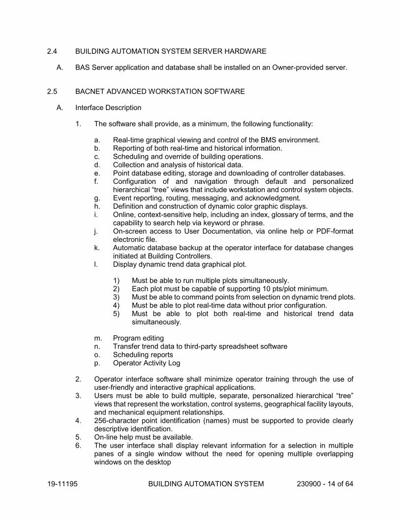
19-11195 BUILDING AUTOMATION SYSTEM 230900 - 14 of 64
2.4 BUILDING AUTOMATION SYSTEM SERVER HARDWARE
A. BAS Server application and database shall be installed on an Owner-provided server.
2.5 BACNET ADVANCED WORKSTATION SOFTWARE
A. Interface Description
1. The software shall provide, as a minimum, the following functionality:
a. Real-time graphical viewing and control of the BMS environment.b. Reporting of both real-time and historical information.c. Scheduling and override of building operations.d. Collection and analysis of historical data.e. Point database editing, storage and downloading of controller databases.f. Configuration of and navigation through default and personalized
hierarchical “tree” views that include workstation and control system objects.g. Event reporting, routing, messaging, and acknowledgment.h. Definition and construction of dynamic color graphic displays.i. Online, context-sensitive help, including an index, glossary of terms, and the
capability to search help via keyword or phrase.j. On-screen access to User Documentation, via online help or PDF-format
electronic file.k. Automatic database backup at the operator interface for database changes
initiated at Building Controllers.l. Display dynamic trend data graphical plot.
1) Must be able to run multiple plots simultaneously.2) Each plot must be capable of supporting 10 pts/plot minimum.3) Must be able to command points from selection on dynamic trend plots.4) Must be able to plot real-time data without prior configuration.5) Must be able to plot both real-time and historical trend data
simultaneously.
m. Program editingn. Transfer trend data to third-party spreadsheet softwareo. Scheduling reportsp. Operator Activity Log
2. Operator interface software shall minimize operator training through the use ofuser-friendly and interactive graphical applications.
3. Users must be able to build multiple, separate, personalized hierarchical “tree”views that represent the workstation, control systems, geographical facility layouts,and mechanical equipment relationships.
4. 256-character point identification (names) must be supported to provide clearlydescriptive identification.
5. On-line help must be available.6. The user interface shall display relevant information for a selection in multiple
panes of a single window without the need for opening multiple overlappingwindows on the desktop

19-11195 BUILDING AUTOMATION SYSTEM 230900 - 15 of 64
7. Provide a graphical user interface that shall minimize the use of keyboard through the use of a mouse or similar pointing device, with a "point and click" approach to menu selection and a “drag and drop” approach to inter-application navigation.
8. Software navigation shall be user friendly by utilizing “forward & back” capability between screens and embedded links to graphics, documents, drawings, trends, schedules, as well as external documents (.doc, .pdf, .xls, etc.) or web addresses that are related to any selected object.
9. Primary selection of objects in the operator interface software shall be available from user defined hierarchical Views, from graphics, or from events in an Event List.
10. Secondary selection of objects in the operator interface software shall be available from links to any objects or external documents related to the primary selection.
11. Links to information related to any selected objects shall be displayed in a consistent manner and automatically defined based on where an object is used in the system.
12. The operator workstation shall be capable of displaying web pages and common document formats (.doc, .xls, .pdf) within the operator workstation application.
13. The software shall provide a multi-tasking type environment that allows the user to run several applications simultaneously.
14. System database parameters shall be stored within an object-oriented database. 15. Standard Windows applications shall run simultaneously with the BMS software. 16. The operator shall be able to work in Microsoft Word, Excel, and other Windows
based software packages, while concurrently annunciating on-line BMS alarms and monitoring information.
17. Provide automatic backup and restore of all Building Controller databases on the workstation hard disk.
18. System configuration, programming, editing, graphics generation shall be performed on-line from the operator workstation software.
19. User shall be able to edit point configuration of any configurable BACnet point that resides in a devices that supports external editing.
20. The software shall also allow the user to configure the alarm management strategy for each point.
21. Users shall have the ability to view the program(s) that is\are currently running in a Building Controller. The display shall mark the program lines with the following: disabled, comment, unresolved, and trace bits.
B. Certifications and Approvals
1. BAS software shall have been tested against the following norms and standards:
a. BACnet Revision 1.13, certified by BACnet Testing Laboratory as BACnet Advanced Workstation Software (BTL B-AWS).
b. IT security compliant with the ISA-99/IEC 62443 Security Level: SL1 c. OPC DA V2.05a and V3.0 Server, certified by the OPC Foundation
certification program. d. UL-listed to UL864 9th edition Standard for Control Units and Accessories
(when installed on a UL-approved computer).
C. Client-Server Connectivity (cSRP)

19-11195 BUILDING AUTOMATION SYSTEM 230900 - 16 of 64
1. Client sessions must be allowed to run on the server and on other devices connected to the server via Intranet, Extranet, or Internet connections.
2. Internet connections, ISP services, as well as necessary firewalls or proxy servers shall be provided by the owner as required to support remote access features.
3. The following client options must be supported:
a. Installed Client.
1) Software application installed from installation media on to the client machine.
2) Installed client software must be configurable to allow it to run in a Closed Mode such that the BAS software can lock down the client machine and prevent users without permission from minimizing the application or running other Windows applications that might cover the BAS software interface.
3) Communication between the server and Installed Clients must be monitored so that any break in communication between the server and an installed client results in notification at the Server and Installed Client machine
4) Installed client machines communicate directly with the BAS server
b. Web Client.
1) Software that runs in a browser on the client machine as a Full Trust client application.
2) Connected to the BAS software server via Microsoft IIS Server.
c. Windows App.
1) Software application downloaded from the BAS server to run on the client machine like an installed application
2) Application must be automatically updated whenever new apps are available at the server.
3) Connected to the BAS software server via Microsoft IIS Server.
4. Each of the client options shall provide the same functionalities including operation and configuration capabilities.
D. Access Rights and User Privileges
1. Access to any client user session must be password protected. 2. Users shall be able to create local user accounts specific to the application
software. 3. Users shall be able to link application user accounts to Active Directory user
accounts for consistent management with domain user accounts. 4. Operator-specific password access protection shall be provided to allow the
administrator/manager to limit users’ workstation control, display and data base manipulation capabilities as deemed appropriate for each user, based upon an assigned user name and password.
5. Operator privileges shall follow the operator to any workstation logged onto.

19-11195 BUILDING AUTOMATION SYSTEM 230900 - 17 of 64
6. The administrator or manager shall be able to further limit operator privileges based on which console an operator is logged on to.
7. The administrator or manager shall be able to grant discrete levels of access and privileges, per user, for each point, graphic, report, schedule, and BMS workstation application.
E. Data Security
1. The FDD software must allow that all communication paths between clients and the server are encrypted and protected against replay attacks as well as data manipulation.
2. Any runtime data transfer between the system server and Web Server (IIS) must be allowed to be encrypted.
3. Communication between any Web Server (IIS) and the Web Clients must be allowed to be encrypted.
4. Passwords must be handled with encrypted storage and transmission 5. The software must support the use of public domain algorithms for cryptographic
functions, including AES, DiffieHellmann, RSA, and SHA-2. No self-coded algorithms shall be allowed.
6. All symmetrical encryption must use 256 bit AES or stronger. 7. All asymmetrical encryption must use 2048 bit or stronger. 8. The software must support the use of commercial certificates for securing client-
server communications. 9. The software must support the use of self-signed certificates to allow local
deployments without the overhead of obtaining commercial certificates.
F. Subsystem Connectivity
1. The FDD application software must be capable of connecting simultaneously to multiple control systems and data sources.
2. Interface software shall simultaneously communicate with Ethernet-connected building level networks.
3. The FDD application software must be capable of receiving data from systems using the following standard protocols:
a. BACnet IP (standard Revision 1.13) b. OPC (OLE for Process Control) OPC DA 2.05, 3.0 c. Modbus TCP d. SNMP (Agent V1 and V2)
G. Activity Logging
1. The operator interface software shall maintain a log of the actions of each individual operator.
2. The software shall provide an application that allows querying based on object name, operator, action, or time range.
3. The software shall provide the ability to generate reports showing operator activity based on object name, operator, action, or time range.
H. Graphics Application

19-11195 BUILDING AUTOMATION SYSTEM 230900 - 18 of 64
1. All graphics shall be available with the same look and functionality whether they are displayed at an installed client console or in a browser.
2. User shall be able to add/delete/modify system graphics for floor plan displays and system schematics for each piece of mechanical equipment (including, air handling units, chilled water systems, hot water boiler systems, and room level terminal units) from standard user interface without the need of any external or specialized tools.
3. The software shall include all necessary tools and procedures for the user to create their own graphics.
4. The software shall provide the user the ability to display real-time point values by animated motion or custom picture control visual representation.
5. The software shall provide animation that depicts movement of mechanical equipment, or air or fluid flow.
6. The software shall provide users the ability to depict various positions in relation to assigned point values or ranges.
7. The software shall provide the ability to add custom gauges and charts to graphic pages.
8. The software must include a library of at least 400 standard control application graphics and symbols for visualizing common mechanical systems, including fans, valves, motors, chillers, AHU systems, standard ductwork diagrams, piping, and laboratory symbols.
9. The Graphics application shall include a set of standard Terminal Equipment controller application-specific background graphic templates. Templates shall provide the automatic display of a selected Terminal Equipment controller’s control values and parameters, without the need to create separate and individual graphic files for each controller.
10. The Graphics application shall be capable of automatically assigning the appropriate symbol for an object (point) selected to be displayed on the graphic based on what the object represents (fan, duct sensor, damper, etc.) when the object is placed on a graphic.
11. The Graphics application shall allow a user to manually override the automatically assigned symbol for an object when a different symbol is desired.
12. The user shall have the ability to add custom symbols to the symbol library. 13. The software shall permit the importing of AutoCAD or scanned pictures for use in
graphics. 14. Graphics must be automatically associated to any points or system objects that
are rendered on the graphic, so that selection of a system object will allow a user to simply navigate to any associated graphic, without the need for manual association.
15. The software must allow users to command points directly off graphics application. 16. Graphic display shall include the ability to depict real-time point values dynamically
with text or animation. 17. Navigation through various graphic screens shall be optionally achieved through a
hierarchical “tree” structure. 18. Graphics viewing shall include dynamic pan zoom capabilities. 19. Graphics viewing shall include the ability to switch between multiple layers with
different information on each layer. 20. Graphics shall include a decluttering capability that allows layers to be
programmatically hidden and displayed based on zoom level.

19-11195 BUILDING AUTOMATION SYSTEM 230900 - 19 of 64
21. Graphics shall be capable of displaying the status of points that have been overridden by a field HAND switch, for points that have been designed to provide a field HAND override capability.
22. The software must provide the ability to create dashboard views consisting of gauges and charts that graphically display system and/ or energy performance.
I. System Performance
1. Comply with the following performance requirements:
a. Graphic Display: Display graphic with minimum 20 dynamic points with current data within 5 seconds.
b. Graphic Refresh: Update graphic with minimum 20 dynamic points with current data within 5 seconds.
c. Object Command: Reaction time of less than 5 seconds between operator command of a binary object and device reaction.
d. Object Scan: Transmit change of state and change of analog values to control units or workstation within 5 seconds.
e. Alarm Response Time: Annunciate alarm at workstation within 2 seconds. Multiple workstations must receive alarms within five seconds of each other.
f. Program Execution Frequency: Programmable controllers shall execute DDC PI control loops, and scan and update process values and outputs at least once per second.
g. Reporting Accuracy and Stability of Control: Report values and maintain measured variables within tolerances as follows:
1) Water Temperature: Plus or minus 1 deg F. 2) Water Flow: Plus or minus 5 percent of full scale. 3) Water Pressure: Plus or minus 2 percent of full scale. 4) Space Temperature: Plus or minus 1 deg F. 5) Ducted Air Temperature: Plus or minus 1 deg F. 6) Outside Air Temperature: Plus or minus 2 deg F. 7) Dew Point Temperature: Plus or minus 3 deg F. 8) Temperature Differential: Plus or minus 0.25 deg F. 9) Relative Humidity: Plus or minus 2 percent. 10) Airflow (Pressurized Spaces): Plus or minus 3 percent of full scale. 11) Airflow (Measuring Stations): Plus or minus 5 percent of full scale. 12) Airflow (Terminal): Plus or minus 10 percent of full scale. 13) Air Pressure (Space): Plus or minus 0.01-inch wg. 14) Air Pressure (Ducts): Plus or minus 0.1-inch wg. 15) Carbon Monoxide: Plus or minus 5 percent of reading. 16) Carbon Dioxide: Plus or minus 50 ppm. 17) Electrical: Plus or minus 5 percent of reading.
J. Reports
1. The software must allow reports shall be executed on demand. 2. The software must allow reports shall be executed via pre-defined schedule. 3. As a minimum, the system shall allow the user to easily obtain the following types
of reports:

19-11195 BUILDING AUTOMATION SYSTEM 230900 - 20 of 64
a. A general listing of all or selected points in the network. b. A status report showing present value and alarm status. c. List of all points currently in alarm. d. List of all points currently in override status. e. List of all disabled points. f. System diagnostic reports including, list of Building panels on line and
communicating, status of all Building terminal unit device points. g. List of alarm strategy definitions. h. List of Building Control panels. i. Point totalization report. j. Point Trend data listings. k. Initial Values report. l. User activity report. m. Event history reports.
K. Scheduling
1. The software shall provide a calendar type format for simplification of time and date scheduling and overrides of building operations.
2. The software shall support the definition of BACnet schedules that are defined at the workstation and are downloaded to Building Controller to ensure time equipment scheduling when PC is off-line, such that the operating software is not required to execute time scheduling. The software must provide the following capabilities for BACnet scheduling capabilities as a minimum:
a. Fully support all BACnet Schedule, Calendar, and Command objects. b. Daily and Weekly schedules. c. Ability to combine multiple points into a logical Command Groups for ease
of scheduling (e.g., all Building 1 lights). d. Ability to schedule for a minimum of up to ten (10) years in advance.
3. The software shall support the definition of schedules that are configured and executed to run at the workstation, to support scheduling of workstation software activities and to support field systems that do not include internal scheduling mechanisms. The software must provide the following capabilities for BACnet scheduling capabilities as a minimum:
a. Schedule predefined reports. b. Schedule Trend collections. c. Schedule automated system backups. d. Schedule commands to be sent to field panels. e. Daily and weekly schedules. f. Setting up and executing Holiday schedules. g. Ability to combine multiple points into a logical Command Groups for ease
of scheduling (e.g., all Building 1 lights). h. Ability to schedule for a minimum of up to ten (10) years in advance.
4. The software shall support the definition of Apogee Equipment Schedules Objects that are defined at the workstation and are downloaded to Building Controller to ensure time equipment scheduling when PC is off-line, such that the operating

19-11195 BUILDING AUTOMATION SYSTEM 230900 - 21 of 64
software is not required to execute time scheduling. The software must provide the following capabilities for BACnet scheduling capabilities as a minimum:
a. Apogee equipment schedule Zones b. Apogee equipment schedule Events c. Configuration of Daily, Weekly, Monthly schedules d. Configuration of Replacement Days
5. The software shall provide the ability for users to override regular weekly schedules through menu selection, graphical mouse action or function key.
6. The software shall provide a timeline view, showing the results of any number of combined selected workstation and field panel controller schedules for an overview of facility operation.
L. Trending
1. Provide trending capabilities that allow the user to easily monitor and preserve records of system activity over an extended period of time.
2. Any system point may be trended automatically at time-based intervals or change of value, both of which shall be user-definable.
3. Trend data shall be collected and stored on hard disk for future diagnostics and reporting.
4. Automatic Trend collection may be scheduled at regular intervals through the same scheduling interface as used for scheduling of equipment.
5. System shall support trending in the same device as the monitor point or in an external device.
6. The software must support configuration of panels that have a trending level threshold, above which the data will be automatically uploaded to the BMS server to prevent overwriting the data in the field panel. The trending level will be user defined in % of available space (e.g., automatically upload when the trend buffer is at 75% of allocated space).
7. Trend data reports shall be provided to allow the user to view all trended point data. 8. Trend data reports may be customized to include individual points or predefined
groups of selected points. 9. The software shall allow the user to view real-time trend data on trend graphical
plot displays.
a. A minimum of ten points may be plotted. b. A combination of real-time and historical data may be plotted. c. Dynamic graphs shall continuously update point values. d. At any time the user may redefine sampling times or range scales for any
point. e. The user may pause the display and take "snapshots" of plot screens to be
stored on the workstation disk for future recall and analysis. f. Exact point values may be viewed on the Trend plot. g. Trend graphs may be printed. h. Operator shall be able to command points by selecting them on the trend
plot. Operator shall be able to zoom in on a specific time range within a plot. i. The Trend Viewer must allow users to configure separate left and right axis
for easier differentiation of point values.

19-11195 BUILDING AUTOMATION SYSTEM 230900 - 22 of 64
j. The Trend Viewer must allow users to display historical data for the samegroup of points at different times simultaneously for easy comparison ofsystem behavior over time.
M. Event Management
1. Event Notification shall be presented to each workstation in a tabular formatapplication, and shall include the following information for each event: name, value,event time and date, event status, priority, acknowledgement information, andalarm count.
2. Only events for which the logged on user has privileges to view shall be displayedon each workstation.
3. The software shall provide the ability to users to limit the list of events displayed ateach workstation (e.g. only show fire events at this workstation, no matter who islogged on).
4. Each event shall have the ability to sound an audible notification based on thecategory of the event.
5. Event List shall have the ability to list and sort the events based on event status,point name, ascending or descending activation time.
6. Directly from the Event List, the user shall have the ability to acknowledge, silencethe event sound, print, or erase each event.
7. The interface shall provide the option to inhibit the erasing of active acknowledgedevents, until they have returned to normal status.
8. The user shall have the ability to navigate to all information related to a selectedpoint in order to command, launch an associated graphic or trended graphical plot,or run a report on a selected point directly from the Event List.
9. Each event shall have a direct link from the Event List to further user-defined pointinformational data.
10. The user shall have the ability to also associate real-time electronic annotations ornotes to each event.
11. Software shall provide the option to configure detailed operating procedures thatguide a user through predetermined standard operating procedures for handlingcritical events. Users shall be able to log completion of each operating step as itis performed.
N. Remote Notification (RENO)
1. Workstations shall be configured to send out messages to numeric pagers,alphanumeric pagers, SMS (Simple Messaging Service, text messaging) Devices,and email accounts based on a point's alarm condition.
2. Email notification must support POP3, IMAP, and SMTP with SSL/TSL3. Communication with external software must be encrypted.4. There shall be no limit to the number of points that can be configured for remote
notification of alarm conditions and no limit on the number of remote devices whichcan receive messages from the system.
5. On a per point basis, system shall be configurable to send messages to anindividual or group and shall be configurable to send different messages todifferent remote devices based on alarm message priority level.
6. System must be configurable to send messages to an escalation list so that if thefirst device does not respond, the message is sent on to the next device after aconfigurable time has elapsed.

19-11195 BUILDING AUTOMATION SYSTEM 230900 - 23 of 64
7. Workstation shall have the ability to send manual messages allowing an operator to type in a message to be sent immediately.
8. Workstation shall have a feature to send a heartbeat message to periodically notify users that they have communication with the system.
O. External Data Access
1. The software shall provide the ability to expose configuration properties and real-time values through CSV files, OPC DA, OPC UA, or REST-based Web Services.
2. The software shall provide the ability for external applications to change configuration and real-time values through OPC DA, OPC UA, or REST-based Web Services.
3. The software shall provide the ability for external applications to access historical Trend data through CSV files or REST-based Web Services.
4. External data access must be secured using the level of permissions configured for users and operator workstations.
5. Web service interfaces must allow for exchanging data (object’s values, events and trend series) between workstation and external applications such as facility management systems, enterprise applications, mobile applications or other value-added services.
6. Documentation describing web services interfaces must be included to allow external developers to write applications that leverage the data exchange.
P. Licensing
1. Software licensing must be allowed to be bound to a dongle or to physical PC hardware.
2. User licenses from all client types shall be from a common pool of client licenses. Licenses for installed and browser-based clients shall not be in separate pools.
3. Provide the number of client licenses as called for here or in the Sequence of Operations.
Q. Data Security
1. The BAS software must allow that all communication paths between clients and the server are encrypted and protected against replay attacks as well as data manipulation.
2. Any runtime data transfer between the system server and Web Server (IIS) must be allowed to be encrypted by Desigo CC.
3. Communication between any Web Server (IIS) and the Web Clients must be allowed to be encrypted.
4. Passwords must be handled with encrypted storage and transmission 5. The software must support the use of public domain algorithms for cryptographic
functions, including AES, DiffieHellmann, RSA, and SHA-2. No self-coded algorithms shall be allowed.
6. All symmetrical encryption must use 256 bit AES or stronger. 7. All asymmetrical encryption must use 2048 bit or stronger. 8. The software must support the use of commercial certificates for securing client-
server communications. 9. The software must support the use of self-signed certificates to allow local
deployments without the overhead of obtaining commercial certificates.

19-11195 BUILDING AUTOMATION SYSTEM 230900 - 24 of 64
10. When using self-signed certificates, the owner of the Desigo CC system is responsible for maintaining their validity status, and for manually adding them to and removing them from the list of trusted certificates.
11. The BAS software shall be compatible with the following Virus Scanners:
a. Kaspersky b. Avira c. McAfee d. Bitdefender e. TrendMicro Office Scan
R. Virtualization
1. The BAS software must be compatible with following Virtualization software packages:
a. VMware®:
1) Virtualization platform: VSphere 6.0 or higher 2) Fault-tolerant software: ESXi 6.0b managed by VCenter Server
Appliance v6.0.0 or higher
b. Stratus®:
1) Virtualization platform: KVM for Linux CentOS v7.0 or higher 2) Fault-tolerant software: everRun Enterprise 7.2 or higher 3) Virtualization platform: Citrix XenServer 6.0.2 or higher 4) Fault-tolerant software: everRun MX 6.2 or higher
S. Subsystem Connectivity
1. The BAS application software must be capable of connecting simultaneously to multiple control systems and data sources.
2. Interface software shall simultaneously communicate with and share data between multiple Ethernet-connected building level networks.
3. The BAS application software must support the following standard protocols:
a. BACnet IP (standard Revision 1.13) b. OPC (OLE for Process Control) OPC DA 2.05, 3.0 c. Modbus TCP d. SNMP (Agent V1 and V2) e. Siemens Apogee P2 f. Siemens XNET
4. Any break in system controller communication must result in a notification at the server.
T. BACnet
1. The Operator Workstation Software shall be capable of BACnet IP communications.

19-11195 BUILDING AUTOMATION SYSTEM 230900 - 25 of 64
2. The Operator Workstation Software shall have demonstrated interoperability during at least one BTL Interoperability Workshop.
3. The Operator Workstation Software shall have demonstrated compliance to BTL B-AWS device classification through BTL listing as specified in ANSI/ASHRAE 135 under revision 1.13 or higher.
4. The BAS software shall meet the BACnet device profile of an Advanced Workstation Server (B-AWS) and Operator Workstation (B-OWS) and shall support the following BACnet BIBBs:
a. Data Sharing
1) DS-RP-A Data Sharing-ReadProperty-A 2) DS-RP-B Data Sharing-ReadProperty-B 3) DS-RPM-A Data Sharing-ReadPropertyMultiple-A 4) DS-RPM-B Data Sharing-ReadPropertyMultiple-B 5) DS-WP-A Data Sharing-WriteProperty-A 6) DS-WP-B Data Sharing-WriteProperty-B 7) DS-WPM-A Data Sharing-WritePropertyMultiple-A 8) DS-COV-A Data Sharing-ChangeofValue-A 9) DS-COVP-A Data Sharing – ChangeofValueProperty-A 10) DS-V-A Data Sharing - View - A 11) DS-AV-A Data Sharing - Advanced View - A 12) DS-M-A Data Sharing - Modify - A 13) DS-AM-A Data Sharing - Advanced Modify - A
b. Scheduling
1) SCHED-VM-A Scheduling-View and Modify-A 2) SCHED-AVM-A Scheduling-Advanced View and Modify-A 3) SCHED-WS-A Scheduling-Weekly Schedule-A
c. Alarm and Event Management
1) AE-N-A Alarm and Event-Notification-A 2) AE-ACK-A Alarm and Event-ACK-A 3) AE-LS-A Alarm and Event-LifeSafety - A 4) AE-VM-A Alarm and Event Management - View and Modify - A 5) AE-AVM-A Alarm and Event Management - Advanced View and
Modify - A 6) AE-VN-A Alarm and Event Management - View Notifications - A 7) AE-AVN-A Alarm and Event Management - Advanced View
Notifications - A
d. Trending
1) T-V-A Trending-Viewing and Modifying Trends-A 2) T-ATR-A Trending-Automated Trend Retrieval-A 3) T-AVM-A Trending-Advanced View and Modify -A
e. Network Management

19-11195 BUILDING AUTOMATION SYSTEM 230900 - 26 of 64
1) NM-CE-A Network Management-Connection Establishment-A
f. Device Management
1) DM-DDB-A Device Management-Dynamic Device Binding-A 2) DM-DDB-B Device Management-Dynamic Device Binding-B 3) DM-DOB-A Device Management-Dynamic Object Binding-A 4) DM-DOB-B Device Management-Dynamic Object Binding-B 5) DM-DCC-A Device Management-DeviceCommunicationControl-A 6) DM-TM-A Device Management-Text Message-A 7) DM-MTS-A Device Management-Manual Time Synchronization-A 8) DM-ATS-A Device Management-Automatic Time Synchronization-A 9) DM-TS-A Device Management-TimeSynchronization-A 10) DM-UTC-A Device Management-UTCTimeSynchronization-A 11) DM-RD-A Device Management-ReinitializeDevice-A 12) DM-BR-A Device Management-Backup and Restore-A 13) DM-LM-A Device Management-List Manipulation-A 14) DM-LM-B Device Management-List Manipulation-B 15) DM-OCD-A Device Management-Object Creation and Deletion-A 16) DM-ANM-A Device Management-Automatic Network Mapping-A 17) DM-ADM-A Device Management-Automatic Device Mapping-A
5. The BAS Server and Workstations shall support the following Data Link Layers:
a. BACnet IP Annex J b. BACnet IP Annex J Foreign Device c. ISO 8802-3, Ethernet (Clause 7)
6. The BAS Server and Workstations shall be able to interact with all of the BACnet objects in the controllers. In addition, the software shall be able to support the following objects as they relate to features in the workstation software:
a. Calendar – Creatable, Deletable b. Command – Creatable, Deletable c. Event Enrollment – Creatable, Deletable d. Notification Class – Creatable, Deletable e. Schedule - Creatable, Deletable
7. The BAS Server and Workstations shall support transmitting and receiving segmented messages.
8. The BAS Server and Workstation shall have the capability to be the BACnet/IP Broadcast Management Device (BBMD) and support foreign devices.
2.6 ENERGY REPORTING AND DATA ANALYTICS SOFTWARE PLATFORM
A. Manufacturers: Subject to compliance with performance requirements and construction techniques.

19-11195 BUILDING AUTOMATION SYSTEM 230900 - 27 of 64
B. Basis-of-Design Product: Subject to compliance with performance requirements and construction techniques, provide:
1. Siemens Industry – Advantage Navigator Software.
C. Acceptable Installers
1. Installer and programmers shall be factory trained representatives of the manufacturer of the software.
D. Provide software to accumulate, log, compile and display energy consumption data and related parameters and measures.
E. Provide an automated reporting software package which will allow utilization of data collected from a sub-metering system and data network. The system should address the following areas:
1. Utility bill tracking 2. Account tracking 3. Savings and analysis 4. Weather Data 5. Weather Normalization 6. Reporting 7. Interval data tracking including meters and equipment data 8. Automated Energy Star benchmarking and greenhouse gas emissions. Provides
a portfolio Comparison and facility ratings trending. Ability to integrate with Energy Star Automated Benchmarking System and generate multi-site Energy Star ranking reports as well as individual site trending of monthly Energy Star score.
9. Web-based hosted solution 10. Customization and Interfaces
F. The software shall integrate to devices provided in other sections of this specification. The contractor shall refer to other sections for the scope of the devices to be integrated into this software, including:
1. Division 23 Building Automation System 2. Division 26 Electrical Panelboards (if specified with smart meters)
G. Coordinate networking, security, and user access to the Web Server interface with the customer’s IT representative. Internet connections, ISP services, firewalls or proxy servers shall be provided by the owner as required to support the Web access feature.
H. Functionality Requirements
1. User Functionality
a. The system shall support multiple user roles in which permissions and access to functions can be defined on a customer basis as described in User Setup.
b. The system shall support a user licensing system.

19-11195 BUILDING AUTOMATION SYSTEM 230900 - 28 of 64
2. Reliability
a. The system shall have measures in place to ensure reliability. This includes but is not limited to 99% uptime, a backup of all databases, and redundant servers.
b. The system shall have a staging and quality control environment to ensure system reliability.
c. The hosting servers shall be on UPS power supply for a minimum of 100 minutes.
d. The hosting facility shall be monitored by personnel 24/7, including the facility, server hardware, and software applications.
e. The hosting facility shall demonstrate strict security access. f. The hosting facility shall demonstrate that the servers operate in a well
controlled and protected environment including temperature and humidity control, fire detection, water protection and server safe fire extinguishing.
3. Development
a. The system shall have a continuous development process with ongoing version releases to support continual system enhancements and the addition of new features.
4. Data Quality and Import / Export
a. They system must have measures in place to ensure the reliability and quality of data. This includes but is not limited to Automated Meter Reset Adjustment features.
b. The system shall have the ability to normalize data for weather by meeting ASHRAE VBDD (Variable-Based Degree Day) method
c. The system shall incorporate a staging environment and have a quality control process to ensure consistency and accuracy of data.
d. The system shall be able to support the import of data from external sources. This includes Utility Bill data – which shall be disaggregated and normalized, manual entry of data, and any interval trend data including meters and BAS points.
e. The system shall have the ability to receive and monitor data on a 1, 5, 15, 30, and 60 minute resolution.
f. The system shall have the ability to import and prorate utility bill data by calendar month.
g. The system shall have an interface allowing users to manually enter data. h. The system shall have the ability to import any interval trend data including
but not limited to meters and BAS points. i. The system shall provide external data accessibility through a REST
(Representational State Transfer) API service. j. The system shall allow users to export data from the system. k. At the termination of the service, all data shall be owned by the customer.
5. General Functionality
a. Data within the energy management system shall be owned by the customer.

19-11195 BUILDING AUTOMATION SYSTEM 230900 - 29 of 64
b. The system shall have supported at least 1000 buildings in order to prove the scalability of the system.
I. Security
1. The application and database servers shall operate in a “demilitarized zone” (DMZ), meaning that the application is protected by firewalls from the internet as well as general access by the provider, software maker and the host’s intranet.
2. Passwords shall be disabled after 5 login attempts with incorrect password. 3. Passwords shall require a minimum of 6 characters. 4. Data transfers between your PC / browser and Advantage Navigator shall be
protected with 256-bit SSL encryption. 5. The system shall use e-mail validation to reset a forgotten password. 6. The system shall support the use of data validation certificates. 7. The system shall support strong authentication via SMS one-time passwords.
J. Reporting Requirements
1. The system shall provide the following ad-hoc reporting capabilities.
a. The system shall allow data to be displayed in multiple chart types. At a minimum it shall support the following charts:
1) Line 2) Bar 3) Stepped Area 4) Area 5) Carpet Plot (Ability to show each day on the x axis and each hour of
the day on the y axis. Each cell provides an automated color coding that indicates the intensity of energy usage of the data point)
6) Stepped line
b. The system shall allow multiple data points to be overlaid on a single chart. c. The system shall allow the user to save any pre-configured ad-hoc reporting
view. d. The system shall allow the user to compare data sets between user
selectable time frames using multiple meters including a rolling most recent period or a fixed period.
e. Data Export
1) The system shall allow the user to export charts in graphical formats including but not limited to PNG, JPG or PDF.
2) The system shall allow the user to export charts in text format including but not limited to CSV.
f. Chart manipulation
1) The system shall allow the user to drag and drop data points. 2) The system shall allow the user to zoom in and zoom out on charts. 3) The system shall allow the user to view data in a tabular format.

19-11195 BUILDING AUTOMATION SYSTEM 230900 - 30 of 64
4) The system shall allow the user to view at least four charts simultaneously.
5) The system shall allow multiple X or Y axis in a single chart. 6) The system shall allow the user to show/hide the X or Y axis. 7) The system shall allow the user to change the scale on the X or Y axis. 8) The system shall allow the user to select colors displayed in each chart. 9) The system shall allow the user to change the chart type. 10) The system shall allow the user to stack bar and area chart types.
2. The system shall provide the following reporting delivery capabilities:
a. Report access via a web-based interface b. E-mailed delivery of standardized reports to the customer via a web-based
scheduling interface c. Allow users to schedule recurring automated e-mail of standardized reports
to an unlimited number of e-mail addresses d. Allow users to save report parameters for easy access of favorite reports
3. The system shall include the following report types and KPIs as listed in Report Types.
4. The system shall have Environmental Reporting including but not limited to EPA EGRID factors and manual entry of Emission Factors.
5. The system shall allow the user to export data and charts in HTML, XLS, CSV, PDF and PPT.
6. The system shall provide the ability to automate reporting on data quality issues.
K. Technical Requirements
1. Remote Access
a. The system shall provide secure remote access that is Certified ISO / IEC 27001.
2. Management Dashboard
a. Google Maps with integrated Geo Pin functionality allowing the user to Toggle KPIs Geo Pin Location based on at least three color coded thresholds definable per individual location.
b. A site ranking system based on energy use index (EUI), energy cost index (ECI), CO2 per square foot, energy consumption versus prior year, cost versus prior year, CO2 versus prior year, energy consumption versus budget, energy star score ranking.
c. The dashboard shall provide the ability to trend data over time.
3. User Interface
a. The system shall be hosted in a centrally located data center. b. The system shall be accessible via a web browser. c. The system shall allow unlimited concurrent users. d. The system shall allow administrators to assign different security access by
user role as specified in User Setup.
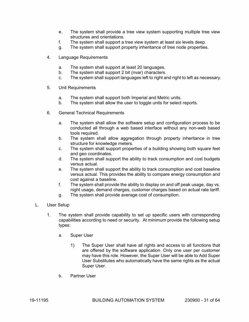
19-11195 BUILDING AUTOMATION SYSTEM 230900 - 31 of 64
e. The system shall provide a tree view system supporting multiple tree view structures and orientations.
f. The system shall support a tree view system at least six levels deep. g. The system shall support property inheritance of tree node properties.
4. Language Requirements
a. The system shall support at least 20 languages. b. The system shall support 2 bit (nvar) characters. c. The system shall support languages left to right and right to left as necessary.
5. Unit Requirements
a. The system shall support both Imperial and Metric units. b. The system shall allow the user to toggle units for select reports.
6. General Technical Requirements
a. The system shall allow the software setup and configuration process to be conducted all through a web based interface without any non-web based tools required.
b. The system shall allow aggregation through property inheritance in tree structure for knowledge meters.
c. The system shall support properties of a building showing both square feet and geo coordinates.
d. The system shall support the ability to track consumption and cost budgets versus actual.
e. The system shall support the ability to track consumption and cost baseline versus actual. This provides the ability to compare energy consumption and cost against a baseline.
f. The system shall provide the ability to display on and off peak usage, day vs. night usage, demand charges, customer charges based on actual rate tariff.
g. The system shall provide average cost of consumption.
L. User Setup
1. The system shall provide capability to set up specific users with corresponding capabilities according to need or security. At minimum provide the following setup types:
a. Super User
1) The Super User shall have all rights and access to all functions that are offered by the software application. Only one user per customer may have this role. However, the Super User will be able to Add Super User Substitutes who automatically have the same rights as the actual Super User.
b. Partner User

19-11195 BUILDING AUTOMATION SYSTEM 230900 - 32 of 64
1) Super Users may Add Partners. The partner role enables Super Users to delegate entire branches (e.g. a building pool) of their tree view to a partner (e.g. to a regional manager within the same organization, or to an external facility management service provider). This gives the Partner User full access rights for the node assigned to him or her, including all of the lower-level nodes and meters it contains.
2) The Partner User has the same rights as the Super User on the delegated node, but can only display the part of the tree view assigned to him or her. The Partner User has an own user management facility, and is therefore able to Add new users (of type Basic User and Advanced User, see next page) and assign nodes to them (within the given part of the tree view).
3) Such Partner Users are invisible to Super Users outside of the partner company. Like the Super User, Partner Users can Add Super User Substitutes but they do not have the authorization to add additional Partners.
c. Advanced User
1) Each node in the tree view (site, building, etc.) can be assigned to an Advanced User who has the following rights:
a) Reading rights - Example: generate and subscribe to reports, display meter lists.
b) Writing rights - Example: Add new buildings and meters, or enter metering data.
2) Deleting rights - Example: delete values, meters or nodes for which the user is the contact person. Note: When a User deletes a meter, the meter and all entered values are automatically moved to the "deleted meters" node (the Super User's "recycle bin"). Therefore, the Super User has the possibility to finally delete meters, or to restore them.
d. Basic User
1) Alternatively, each node can be assigned to a Basic User who has the following rights:
a) Reading rights - Example: generate and subscribe to reports, display meter lists.
b) Writing rights - Enter and edit meter readings only (no meter exchange).
c) Deleting rights - Delete individual meter readings only.
M. Report Types
1. The software shall support the following report types:
a. Load Profiles (Arrangement of all load levels over time)
1) Daily Max kW

19-11195 BUILDING AUTOMATION SYSTEM 230900 - 33 of 64
2) Monthly Max kW 3) # of Occ. Of peak load 4) Trend of a single KPI 5) Daily Avg kW 6) Demand 7) Monthly Avg kW 8) Daily Total kWh 9) Gas 10) Monthly Total kWh 11) Daily Avg kWh 12) Steam 13) Monthly Avg kWh 14) On Peak 15) Temperatures 16) Off Peak 17) Fuel / Oil 18) % Breakdown by load 19) Chilled Water 20) Flow 21) Frequency (Any trend data from a BAS System)
b. Operational Analysis
1) Daily Max 2) Daily Min 3) Total usage 4) Daily Avg Usage
c. Performance Indicators
1) Opportunity Score - Ranked by opportunity to reduce energy use 2) Target Energy Use Intensity
d. Consumption
1) Daily Max 2) Total portfolio energy usage 3) Total portfolio emissions usage 4) Electricity 5) Absolute and pct breakdown of energy usage (electricity) 6) Spikes 7) Total and Average (electricity) 8) Total 9) Total portfolio cumulative energy usage 10) Daily Min 11) Energy Use Intensity 12) Emissions Use Intensity 13) Demand 14) Gas 15) Average and r-value correlation (Electricity vs. outside air temp) 16) Total usage
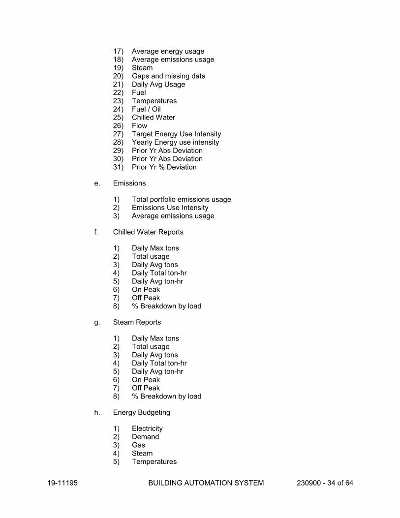
19-11195 BUILDING AUTOMATION SYSTEM 230900 - 34 of 64
17) Average energy usage 18) Average emissions usage 19) Steam 20) Gaps and missing data 21) Daily Avg Usage 22) Fuel 23) Temperatures 24) Fuel / Oil 25) Chilled Water 26) Flow 27) Target Energy Use Intensity 28) Yearly Energy use intensity 29) Prior Yr Abs Deviation 30) Prior Yr Abs Deviation 31) Prior Yr % Deviation
e. Emissions
1) Total portfolio emissions usage 2) Emissions Use Intensity 3) Average emissions usage
f. Chilled Water Reports
1) Daily Max tons 2) Total usage 3) Daily Avg tons 4) Daily Total ton-hr 5) Daily Avg ton-hr 6) On Peak 7) Off Peak 8) % Breakdown by load
g. Steam Reports
1) Daily Max tons 2) Total usage 3) Daily Avg tons 4) Daily Total ton-hr 5) Daily Avg ton-hr 6) On Peak 7) Off Peak 8) % Breakdown by load
h. Energy Budgeting
1) Electricity 2) Demand 3) Gas 4) Steam 5) Temperatures

19-11195 BUILDING AUTOMATION SYSTEM 230900 - 35 of 64
6) Fuel / Oil 7) Chilled Water 8) Budget 9) Deviation absolute 10) Deviation % (Ability generate a report with multiple sites and rank by %
deviation from a budget)
i. Cost Analysis / Budgeting
1) Total portfolio energy cost 2) Energy cost Intensity 3) Average energy cost 4) Electricity 5) Demand 6) Gas 7) Steam 8) Fuel / Oil 9) Chilled Water 10) Budget 11) Deviation absolute 12) Deviation %
j. Energy Star / Weather Normalization
1) Energy Star Score 2) Total consumption (Electricity & Gas) 3) Weather normalized consumption (System shall support a Variable-
Base Degree Day Model (VBDD) program to automatically calculate a customized Balance Point Temperature for each site.)
4) absolute deviation from prior year 5) % deviation from prior year
k. Critical Environments (if such as system is included in the project)
1) % of ventilation in occupied mode due to Baseline airflow, cooling and ventilation
2) % of ventilation in the Unoccupied mode due to baseline airflow, cooling and ventilation
3) Air Volume and reheat valve position 4) % of Satisfactory Temperature 5) Savings in CFM and currency 6) Statement of Performance criteria 7) Air volume reduction 8) Target Hood Ratio Benchmark 9) % of Satisfactory Exhaust Volume 10) % of Satisfactory Exhaust Volume 11) % of Satisfactory Directional Airflow 12) % of Satisfactory Ventilation
l. Chiller Plant Optimization (if such as system is included in the project)

19-11195 BUILDING AUTOMATION SYSTEM 230900 - 36 of 64
1) Plant Efficiency (kW/Ton) 2) Target Savings 3) Actual Savings 4) Total Operating Hours 5) Total Chilled Water usage 6) Savings: Actual vs. Predicted
m. Site ranking by customized building attributes
1) Energy use index (EUI) 2) Energy cost index (ECI) 3) Total CO2 4) Energy consumption versus prior year 5) Cost versus prior year 6) Energy consumption versus budget 7) Energy cost versus budget 8) Energy star score
2.7 WEB BASED CONTROLLER SOFTWARE FOR CONFIGURATION, PROGRAMMING AND OPERATORS
A. The purpose of this specification is to allow the Owner/Operator to have the same controller programming capabilities as the Controls Contractor Technician without additional software, tools, or licenses.
1. The controller programming shall be accessible to any user via a Web Services application over an IP or Internet connection through port 80.
B. The following types of controllers shall have this feature:
1. All BACnet BC level controllers 2. Network Engine Controllers 3. Controllers on equipment or sequences customized for this job
C. Manufacturer:
1. Siemens Launch Pad™ (compatible with PXC controllers) 2. Controllers from other manufacturers shall meet the capabilities of this
specification
D. The controller shall come with the software built-in and delivered with the controller as part of the controller purchase. It shall not require a separate software license to enable the software capability.
1. The software shall be provided as an integral part of DDC Controllers and shall not be dependent upon any higher level computer or another controller for execution.
E. The software application shall be accessible from a PC using Web Services, but shall use all of its own services and data files so as to not be susceptible to Microsoft Windows operating systems based viruses.

19-11195 BUILDING AUTOMATION SYSTEM 230900 - 37 of 64
F. Access to the controller software shall be username and password protected. User shall be authenticated by the controller.
G. The embedded Web Services shall provide the following functionality to users, based on their access and privilege rights:
1. Point Navigation – Provide a screen that allows users to see all of the points that are active in the system. The points shall include hardwired, software, schedules, trends, alarms and network setup.
a. The point navigation shall display the point name, descriptor, command priority, alarm status, and current value.
b. The user shall be able to run and print a pre-configured point log report through a web interface client that shows the point name, descriptor, command priority, alarm status, and current value.
c. The interface and report shall allow selection filter such that the operator can select or deselect the types of point that are visible.
2. Alarm Display –displays current BAS alarms to which the user has access will be displayed. Users will be able to acknowledge active alarms, erase resolved alarms, and directly link to the Point Commanding feature.
a. The alarm display must provide a filter that displays all alarms whether acknowledged or not.
b. The alarm display must provide a filter that displays only alarms that have not yet been acknowledged.
c. The alarm display must provide a persistent indication whenever there is one or more unacknowledged alarm in any connected field panel.
3. Point details – users will have access to point detail information including operational status, operational priority, physical address, and alarm limits, for point objects to which they have access rights.
4. Point Commanding – users will be able to override and command points they have access to via the Web browser interface.
5. Scheduling – allows operators, depending on their current user privileges, to override schedules selected by date, and to modify the properties of a selected schedule.
a. The scheduler display must be able to represent facility mode schedules in a graphical format.
6. Trend Data Report – allows users to run and print a pre-configured trend data report for historical data reporting, including a representation of the alarm status of the each point for each Trend sample. The report shall allow selection of individual points or wildcard selection of points.
a. Trend data shall be exportable to a data file, such as .csv or other comparable.
7. Network navigation - Provide a screen that allows users to navigate to the panels and terminal units via the network architecture.

19-11195 BUILDING AUTOMATION SYSTEM 230900 - 38 of 64
H. The web server shall be able to send SMTP text messages to notify users of alarm status. The owners shall provide a mail server and a connection port. SSL shall not be required.
I. The operator shall be able to add modify and delete controller database program, including points, schedules, alarms, and trends.
1. The operator shall be able to edit the custom program in the field panel that executes the sequences of operations, control loops and logic for the systems controlled.
2. The operator shall be able to add terminal unit controllers that reside on field panel subnetworks.
J. Internet connections, ISP services, as well as necessary firewalls or proxy servers shall be provided by the Owner as required to support the Web access feature.
K. Coordinate with the Owner/Operator’s IT representatives to setup and allow access to controllers via IP connections and Web Services through port 80.
1. It shall be the responsibility of the Owner/IT to setup and maintain security for user access to the private networks.
2. Coordinate IP addressing scheme.
2.8 DIRECT DIGITAL CONTROLLER SOFTWARE
A. Provide a full capability user license to the owner for the operator to be able to see, modify, create, upload, download and save control programs to the DDC controllers.
B. The software program shall be provided as an integral part of DDC Controllers and shall not be dependent upon any higher level computer or another controller for execution.
C. The software shall be provided with an interactive HELP function to assist operators with syntax, abbreviations, commands and saving programs.
D. Point naming and communication format:
1. All points, panels, and programs shall be identified by a 30-character name. All points shall also be identified by a 16-character point descriptor. The same names shall be displayed at both Building Controller and the Operator Interface.
2. All digital points shall have a consistent, user-defined, two-state status indication with 8 characters minimum (e.g., Summer, Enabled, Disabled, Abnormal).
3. The Building Controller Software shall be capable of BACnet communications. The BACnet Building Controller (B-BC) shall have demonstrated interoperability during at least one BTL Interoperability Workshop, have demonstrated compliance to BTL through BTL listing and shall substantially conform to BACnet Building Controller (B-BC) device profile as specified in ANSI/ASHRAE 135-2004, Annex L.
E. System Security

19-11195 BUILDING AUTOMATION SYSTEM 230900 - 39 of 64
1. User access shall be secured using individual security passwords and user names. 2. Passwords shall restrict the user to the objects, applications, and system functions
as assigned by the system manager. 3. Building Controllers shall be able to assign a minimum of 50 passwords access
and control priorities to each point individually. The logon password (at any Operator Interface or portable operator terminal) shall enable the operator to monitor, adjust and control only the points that the operator is authorized for. All other points shall not be displayed at the Operator Interface or portable terminal. Passwords and priorities for every point shall be fully programmable and adjustable.
4. User Log On/Log Off attempts shall be recorded. 5. The system shall protect itself from unauthorized use by automatically logging off
following the last keystroke. The delay time shall be user-definable. 6. Use of workstation resident security as the only means of access control is not an
acceptable alternative to resident system security in the DDC controller software.
F. User Defined Control Applications: The applications software shall program DDC routines to meet the sequences of operations.
1. Building Controllers shall have the ability to perform energy management routines including but not limited to time of day scheduling, calendar-based scheduling, holiday scheduling, temporary schedule overrides, start stop time optimization, automatic daylight savings time switch over, night setback control, enthalpy switch over, peak demand limiting, temperature-compensated duty cycling, heating/cooling interlock, supply temperature reset, priority load shedding, and power failure restart.
2. The Building Controllers shall have the ability to perform the following pre tested control algorithms:
a. Two position with differential control and time delays b. Floating control c. Proportional control d. Proportional plus integral control e. Proportional, integral, plus derivative control f. Automatic tuning of control loops g. Model-free adaptive control h. Start Stop Time Optimization
3. Controllers shall be able to execute custom, job-specific processes defined by the user, to automatically perform calculations and special control routines.
4. Each controller shall support plain language text comment lines in the operating program to allow for quick troubleshooting, documentation, and historical summaries of program development.
G. Peer-to-peer access to other DDC controllers
1. It shall be possible to use any actual or virtual point data or status, any system calculated data, a result from any process, or any user-defined constant in any controller in the system.
2. Any process shall be able to issue commands to points in any and all other controllers in the system.

19-11195 BUILDING AUTOMATION SYSTEM 230900 - 40 of 64
3. Processes shall be able to generate operator messages and advisories to other operator I/O devices. A process shall be able to directly send a message to a specified device or cause the execution of an advanced annunciation feature, such as:
a. Generate a report b. Annunciate an alarm c. Issue a text message or email
H. Alarm Management
1. Alarm management shall be provided within the controller software to monitor and direct alarm information to operator devices.
2. Each Building Controller shall perform distributed, independent alarm analysis, minimize network traffic and prevent alarms from being lost. At no time shall the Building Controllers ability to report alarms be affected by either operator or activity at a PC workstation, local I/O device or communications with other panels on the network.
3. Conditional alarming shall allow generation of alarms based upon user defined multiple criteria.
4. An Alarm “shelving” feature shall be provided to disable alarms during testing. (Pull the Plug, etc.).
5. Binary Alarms. Each binary alarm object shall be set to alarm based on the operator-specified state. Provide the capability to automatically and manually disable alarming.
6. Analog Alarms. Each analog alarm object shall have both high and low alarm limits. Alarming must be able to be automatically and manually disabled.
7. All alarm shall include the point's user-defined language description and the time and date of occurrence.
8. Alarm reports and messages shall be routed to user-defined list of operator workstations, or other devices based on time and other conditions. An alarm shall be able to start programs, print reports, be logged in the event log, generate custom messages, and display graphics.
9. The user shall be able to add a 200-character alarm message to each alarm point to more fully describe the alarm condition or direct operator response. Each Building Controller shall be capable of storing a library of at least 50 alarm messages. Each message may be assigned to any number of points in the Controller.
10. Operator-selected alarms shall be capable of initiating a trigger to an advanced annunciation, such as text, email, etc.
11. An alarm history log shall report the start of the alarm condition, acknowledgement by a user and return of the alarm to normal condition.
I. Scheduling:
1. Provide a comprehensive menu driven program to automatically start and stop designated multiple objects or events in the system according to a stored time.
2. Schedules shall reside in the building controller and shall not rely on external processing or network.

19-11195 BUILDING AUTOMATION SYSTEM 230900 - 41 of 64
3. It shall be possible to define a group of objects as a custom event (i.e., meeting, athletic activity, etc.). Events can then be scheduled to operate all necessary equipment automatically.
4. For points assigned to one common load group, it shall be possible to assign variable time delays between each successive start and/or stop within that group.
5. The operator shall be able to define the following information:
a. Time, day b. Commands such as on, off, auto, etc. c. Time delays between successive commands. d. There shall be provisions for manual overriding of each schedule by an
authorized operator.
6. It shall be possible to schedule calendar-based events up to one year in advance based on the following:
a. Weekly Schedule. Provide separate schedules for each day of the week. Each of these schedules should include the capability for start, stop, optimal start, optimal stop, and night economizer. When a group of objects are scheduled together as an Event, provide the capability to adjust the start and stop times for each member.
b. Exception Schedules. Provide the ability for the operator to designate any day of the year as an exception schedule. Exception schedules may be defined up to a year in advance. Once an exception schedule is executed, it will be discarded and replaced by the standard schedule for that day of the week.
J. Peak Demand Limiting (PDL):
1. The Peak Demand Limiting (PDL) program shall limit the consumption of electricity to prevent electrical peak demand charges.
2. PDL shall continuously track the amount of electricity being consumed, by monitoring one or more electrical kilowatt-hour/demand meters. These meters may measure the electrical consumption (kWh), electrical demand (kW), or both.
3. PDL shall sample the meter data to continuously forecast the demand likely to be used during successive time intervals.
4. If the PDL forecasted demand indicates that electricity usage is likely to exceed a user preset maximum allowable level, then PDL shall automatically shed electrical loads.
5. Once the demand peak has passed, loads that have been shed shall be restored and returned to normal control.
K. Temperature-compensated duty cycling
1. User defined conditions shall be able to initiate a Duty Cycle Control Program. 2. The Duty Cycle Control Program (DCCP) shall be configured to periodically stop
and start loads according to various patterns. 3. The loads shall be cycled such that there is a net reduction in both the electrical
demands and the energy consumed.

19-11195 BUILDING AUTOMATION SYSTEM 230900 - 42 of 64
L. Automatic Daylight Savings Time Switchover. The system shall provide automatic time adjustment for switching to/from Daylight Savings Time.
M. Night setback control. The system shall provide the ability to automatically adjust setpoints for night control.
N. Enthalpy switchover (economizer). The Building Controller Software (BCS) shall control the position of the air handler relief, return, and outside air dampers. If the outside air dry bulb temperature falls below changeover setpoint the BCS will modulate the dampers to provide 100 percent outside air. The user will be able to quickly change over to an economizer system based on dry bulb temperature and will be able to override the economizer cycle and return to minimum outside air operation at any time.
O. Control Loop Algorithm
1. Provide a PID (proportional-integral-derivative) closed-loop control algorithm with direct or reverse action and anti-windup. The algorithm shall calculate a time-varying analog value that is used to position an output or stage a series of outputs. The controlled variable, setpoint, and weighting parameters shall be accessible from the operator workstation.
P. Adaptive Loop Tuning
1. Building Controllers shall also provide high resolution sampling capability for verification of DDC control loop performance. Documented evidence of tuned control loop performance shall be provided on a monthly, seasonal, quarterly, annual period.
2. For Model-Free Adaptive Control loops, evidence of tuned control loop performance shall be provided via graphical plots or trended data logs. Graphical plots shall minimally include depictions of setpoint, process variable (output), and control variable (e.g., temperature). Other parameters that may influence loop control shall also be included in the plot (e.g., fan on/off, mixed-air temp).
3. For PID control loops, operator-initiated automatic and manual loop tuning algorithms shall be provided for all operator-selected PID control loops. Evidence of tuned control loop performance shall be provided via graphical plots or trended data logs for all loops.
a. In automatic mode, the controller shall perform a step response test with a minimum one-second resolution, evaluate the trend data, calculate the new PID gains and input these values into the selected LOOP statement.
b. Loop tuning shall be capable of being initiated either locally at the Building Controller, from a network workstation or remotely using dial-in modems. For all loop tuning functions, access shall be limited to authorized personnel through password protection.
Q. Logic programming: Provide a software routine that can build ladder logic to control using many conditional statements.
1. The logic programming syntax shall be able to combine ladder logic with other software features, such as combining status, scheduling, PDL and alarm conditions into one conditional decision.

19-11195 BUILDING AUTOMATION SYSTEM 230900 - 43 of 64
2. Logic programming shall be able to reference conditions in any other controller in the system.
R. Staggered Start:
1. This application shall prevent all controlled equipment from simultaneously restarting after a power outage. The order in which equipment (or groups of equipment) is started, along with the time delay between starts, shall be user definable in an application and shall not require written scripts or ladder logic.
2. Upon the resumption of power, each Building Controller shall analyze the status of all controlled equipment, compare it with normal occupancy scheduling and turn equipment on or off as necessary to resume normal operations.
S. Totalization Features:
1. Run-Time Totalization. Building Controllers shall automatically accumulate and store run-time hours for all digital input and output points. A high runtime alarm shall be assigned, if required, by the operator.
2. Consumption totalization. Building Controllers shall automatically sample, calculate and store consumption totals on a daily, weekly or monthly basis for all analog and digital pulse input type points.
3. Event totalization. Building Controllers shall have the ability to count events such as the number of times a pump or fan system is cycled on and off. Event totalization shall be performed on a daily, weekly or monthly basis for all points. The event totalization feature shall be able to store the records associated with events before reset.
T. Data Collection:
1. A variety of historical data collection utilities shall be provided to manually or automatically sample, store, and display system data for all points.
2. Building Controllers shall store point history data for selected analog and digital inputs and outputs:
3. Any point, physical or calculated may be designated for trending. Any point, regardless of physical location in the network, may be collected and stored in each Building Controllers point group.
4. Two methods of collection shall be allowed: either by up to four pre-defined time intervals or upon a pre-defined change of value. Sample intervals of l minute to 7 days shall be provided.
5. Each Building Controller shall have a dedicated RAM-based buffer for trend data and shall be capable of storing a minimum of 10,000 data samples.
6. Trend data shall be stored at the Building Controllers and uploaded to the workstation when retrieval is desired. Uploads shall occur based upon either user-defined interval, manual command or when the trend buffers are full. All trend data shall be available for use in third-party personal computer applications.
2.9 BACNET BUILDING CONTROLLERS

19-11195 BUILDING AUTOMATION SYSTEM 230900 - 44 of 64
A. Provide all necessary hardware for a complete operating system as required. The Building Controller shall be able to operate as a standalone panel and shall not be dependent upon any higher level computer or another controller for operation.
B. The primary controller basis of design is Siemens PX Modular and Compact Controllers (PXC). Alternates includes:
1. Schneider Electric B4920 or BCX-1 at each unit with IO blocks local to BCX-1 in local control panel. BACNet/IP communicating at 100 MB/Sec, BTL Listed Building Controllers with on board BBMD ( BACnet Broadcast Messaging Device) capability. B3800 series is not acceptable without a BACnet/IP port
2. Honeywell CIPER Model 50 Controller and must support rapid spanning tree protocol (RSTP). Honeywell spyder is not acceptable.
C. This controller shall have the BTL listing and meet the BACnet device profile of a Building Controller (B-BC) and shall support the following BACnet BIBBs:
1. Data Sharing
a. Data Sharing-Read Property-Initiate, Execute (DS-RP-A,B) b. Data Sharing-Read Property Multiple- Initiate, Execute (DS-RPM-A,B) c. Data Sharing-Write Property- Initiate, Execute (DS-WP-A,B) d. Data Sharing-Write Property Multiple- Execute (DS-WPM-B) e. Data Sharing-COV- Initiate, Execute (DS-COV-A,B) f. Data Sharing-COV-Unsolicited- Initiate, Execute (DS-COVU-A,B)
2. Scheduling
a. Scheduling-Internal- Execute (SCHED-I-B) b. Scheduling-External- Execute (SCHED-E-B)
3. Trending
a. Trending-Viewing and Modifying Trends - Initiate (T-VMT-A) b. Trending-Viewing and Modifying Trends Internal- Execute (T-VMT-I-B) c. Trending-Viewing and Modifying Trends-External- Execute (T-VMT-E-B) d. Trending-Automated Trend Retrieval- Execute (T-ATR-B)
4. Network Management
a. Network Management-Connection Establishment- Initiate (NM-CE-A)
5. Alarming
a. Alarm and Event-Notification- Initiate (AE-N-A) b. Alarm and Event-Notification Internal- Execute (AE-N-E-B) c. Alarm and Event-Notification External- Execute (AE-N-E-B) d. Alarm and Event-ACK- Initiate, Execute (AE-ACK-A,B) e. Alarm and Event –Alarm Summary- Execute (AE-ASUM-B) f. Alarm and Event –Enrollment Summary- Execute (AE-ESUM-A,B) g. Alarm and Event –Information- Initiate, Execute (AE-ESUM-A,B)

19-11195 BUILDING AUTOMATION SYSTEM 230900 - 45 of 64
6. Device Management
a. Device Management-Dynamic Device Binding- Initiate, Execute (DM-DDB-A,B)
b. Device Management-Dynamic Object Binding- Initiate, Execute (DM-DOB-A,B)
c. Device Management-Device Communication Control- Execute (DM-DCC-B) d. Device Management-Private Transfer- Initiate, Execute (DM-PT-A,B) e. Device Management-Text Message- Initiate, Execute (DM-TM-A,B) f. Device Management-Time Synchronization- Execute (DM-TS-B) g. Device Management-Reinitialize Device- Execute (DM-RD-B) h. Device Management-Backup and Restore- Execute (DM-RD-B) i. Device Management-List Manipulation- Execute (DM-RD-B) j. Device Management-Object Creation and Deletion- Execute (DM-OCD-B)
7. The Building Level Controller shall support the following Data Link Layers:
a. BACnet IP Annex J b. BACnet IP Annex J Foreign Device c. MS/TP Master (Claus 9)
8. The Building Level Controller shall be able to interact with all of the BACnet objects in the controllers. In addition, the software shall be able to support the following objects as they relate to features in the workstation software:
a. Calendar – Creatable, Deletable b. Command – Creatable, Deletable c. Event Enrollment – Creatable, Deletable d. Notification Class – Creatable, Deletable e. Schedule - Creatable, Deletable
9. The Building Level Controller shall support transmitting and receiving segmented messages.
10. The Building Level Controller shall have the capability to be the BACnet/IP Broadcast Management Device (BBMD) and support foreign devices.
11. The Building Level Controller shall have the capability to act as a BACnet router between MS/TP subnetworks and BACnet/IP.
D. Computing power and memory minimum:
1. A 32-bit, stand-alone, multi-tasking, multi-user, real-time 100MHz digital control microprocessor module.
2. Inputs shall be 16-bit minimum analog-to-digital resolution 3. Outputs shall be 10-bit minimum digital-to-analog resolution 4. Memory module (24 Megabyte, minimum) to accommodate all Primary Control
Panel software requirements, including but not limited to, its own operating system and databases (see Controllers Software section), including control processes, energy management applications, alarm management applications, historical/trend data for points specified, maintenance support applications, custom processes, operator I/O, dial-up communications.
5. Real time clock and battery

19-11195 BUILDING AUTOMATION SYSTEM 230900 - 46 of 64
6. Data collection/ Data Trend module sized for 10,000 data samples. 7. Flash Memory Firmware: Each Building Level Control Panel shall support
firmware upgrades without the need to replace hardware.
E. Onboard or Modular hardware and connections:
1. Primary Network communication module, if needed for primary network communications.
2. Secondary Network communication module, if needed for secondary network communications.
3. RJ45 port 10/100Mbaud 4. RS485 ports for subnetworks and point expansion 5. Man to Machine Interface port (MMI) 6. USB Port
F. Input and Output Points Hardware
1. Input/output point modules as required including spare capacity. 2. Input/output point modules shall have removable terminal blocks. 3. Monitoring of the status of all hand-off-auto switches. 4. Monitoring of all industry standard types of analog and digital inputs and outputs,
without the addition of equipment to the primary control panel. 5. Local status indication for each digital input and output for constant, up-to-date
verification of all point conditions without the need for an operator I/O device. Each primary control panel shall perform diagnostics on all inputs and outputs and a failure of any input or output shall be indicated both locally and at the operator workstation.
6. Graduated intensity LEDs or analog indication of value for each analog output.
G. Code compliance
1. Approvals and standards: UL916; CE; FCC 2. Provide UL864-UUKL at all primary panels.
H. Accessories:
1. Appropriate NEMA rated metal enclosure. 2. Power supplies as required for all associated modules, sensors, actuators, etc.
I. The operator shall have the ability to manually override automatic or centrally executed commands at the primary control panels via local, point discrete, on-board hand/off/auto operator override switches. If on board switches are not available, provide separate control panels with HOA switches. Mount panel adjacent to primary control panel. Provide hand/off/auto switch for each digital output, including spares.
J. Each Building Level Control Panel shall continuously perform self-diagnostics on all hardware modules and network communications. The System Level Control Panel shall provide both local and remote annunciation of any detected component failures, low battery conditions or repeated failure to establish communication with any system.

19-11195 BUILDING AUTOMATION SYSTEM 230900 - 47 of 64
K. Panel setup, point definitions and sequencing diagrams shall be backed up on EEPROM memory.
L. Power loss. In the event of the loss of power, there shall be an orderly shutdown of all Building Controllers to prevent the loss of database or operating system software. Non-volatile memory shall be incorporated for all critical controller configuration data and battery backup shall be provided to support the real-time clock and all volatile memory for a minimum of 30 days.
M. Building Level control panels shall provide at least two serial data communication ports for operation of operator I/O devices such as industry standard printers, operator terminals, modems and portable laptop operator's terminals. Primary control panels shall allow temporary use of portable devices without interrupting the normal communications, operation of permanently connected modems, printers or terminals.
N. Building Level Controllers shall have the capability to serve as a gateway between Modus subnetworks and BACnet objects. Provide software, drives and programming.
O. Isolation shall be provided at all primary control panel terminations, as well as all field point terminations to suppress induced voltage transients consistent with IEEE Standards 587-1980.
P. Spare Capacity: Provide enough inputs and outputs to handle the equipment shown to be “future” on drawings and 10% more of each point type. Provide all hardware modules, software modules, processors, power supplies, communication controllers, etc. required to ensure adding a point to the spare point location only requires the addition of the appropriate sensor/actuator and field wiring/tubing.
Q. Environment.
1. Controller hardware shall be suitable for the anticipated ambient conditions. 2. Controllers used outdoors and/or in wet ambient conditions shall be mounted
within waterproof enclosures and shall be rated for operation at 0°C to 49°C (32°F to 120°F).
3. Controllers used in conditioned space shall be mounted in dust-proof enclosures and shall be rated for operation at 0°C to 49°C (32°F to 120°F).
4. Controller hardware shall be optionally suitable for rooftop environments.
R. Immunity to power and noise.
1. Controller shall be able to operate at 90% to 110% of nominal voltage rating and shall perform an orderly shutdown below 80% nominal voltage.
2. Operation shall be protected against electrical noise of 5 to 120 Hz and from keyed radios up to 5 W at 1 m (3 ft).
3. Isolation shall be provided at all primary network terminations, as well as all field point terminations to suppress induced voltage transients consistent with:
a. RF-Conducted Immunity (RFCI) per ENV 50141 (IEC 1000-4-6) at 3V. b. Electro Static Discharge (ESD) Immunity per EN 61000-4-2 (IEC 1000-4-2)
at 8 kV air discharge, 4 kV contact.

19-11195 BUILDING AUTOMATION SYSTEM 230900 - 48 of 64
c. Electrical Fast Transient (EFT) per EN 61000-4-4 (IEC 1000-4-4) at 500V signal, 1 kV power.
d. Output Circuit Transients per UL 864 (2,400V, 10A, 1.2 Joule max).
4. Isolation shall be provided at all Building Controller’s AC input terminals to suppress induced voltage transients consistent with:
a. IEEE Standard 587 1980 b. UL 864 Supply Line Transients c. Voltage Sags, Surge, and Dropout per EN 61000-4-11 (EN 1000-4-11)
2.10 CONTROL PANELS
A. Controllers in mechanical rooms shall be mounted in NEMA 1 enclosures.
B. Controllers in areas where moisture is a concern shall be mounted in NEMA 12 enclosures.
C. Controllers installed outdoors shall be mounted in NEMA 4X enclosures. Provide heaters where freezing temperatures are normally experienced.
D. Mount on walls at an approved location or provide a free standing rack.
E. Panels shall be constructed of 16 gauge, furniture-quality steel, or extruded-aluminum alloy, totally enclosed, with hinged doors and keyed lock and with ANSI 61 gray polyester-powder painted finish, UL listed. Provide common keying for all panels.
F. Provide power supplies for control voltage power.
G. Dedicate 1 power supply to the DDC controller. Other devices shall be on a separate power supply, unless the power for the control device is derived from the controller terminations.
H. Power supplies for controllers shall be a transformer with a fuse or circuit breaker. Power supplies for other devices can be plain transformers.
I. All power supplies for 24V low voltage wiring shall be class 2 rated and less than 100VA. If low voltage devices require more amps, then provide multiple power supplies. If a single device requires more amps, then provide a dedicated power supply in a separate enclosure and run a separate, non-class 2 conduit to the device.
J. Surge transient protection shall be incorporated in design of system to protect electrical components in all DDC Controllers and operator’s workstations.
K. All devices in a panel shall be permanently mounted, including network switches, modems, media converters, etc.
L. Provide a pocket to hold documentation.
2.11 SENSORS

19-11195 BUILDING AUTOMATION SYSTEM 230900 - 49 of 64
A. General
1. Provide mounting hardware for all devices, including actuator linkages, wells, installation kits for insertion devices, wall boxes and fudge plates, brackets, etc.
2. If a special tool is required to mount a device, provide that tool.
B. Terminal Unit Space Thermostats
1. Each controller performing space temperature control shall be provided with a matching room temperature sensor.
a. Plain Space Temperature Sensors – Wired: Where called for in the sequences or on the drawings, provide sensors with plain covers.
b. The sensing element for the space temperature sensor shall be thermistor type providing the following.
1) Element Accuracy: + /- 1.0°F 2) Operating Range: 55 to 95°F 3) Set Point Adjustment Range: 55 to 95°F 4) Calibration Adjustments: None required 5) Installation: Up to 100 ft. from controller 6) Auxiliary Communications Port: As required 7) Local LCD Temperature Display: As required 8) Setpoint Adjustment Dial As required 9) Occupancy Override Switch As required
c. Auxiliary Communication Port. Each room temperature sensor shall include a terminal jack integral to the sensor assembly. The terminal jack shall be used to connect a portable operator's terminal to control and monitor all hardware and software points associated with the controller. RS-232 communications port shall allow the operator to query and modify operating parameters of the local room terminal unit from the portable operator’s terminal.
2. Digital Display temperature sensor specifications – Wired:
a. As called for in the sequences of operations or on the drawings, provide temperature sensors with digital displays.
b. The sensing element for the space temperature sensor must be IC-based and provide the following.
1) Digitally communicating with the Application Specific Controller. 2) Mountable to and fully covering a 2 x 4 electrical junction box without
the need for an adapter wall plate. 3) IC Element Accuracy: +/- 0.9°F 4) Operating Range: 55 to 95°F 5) Setpoint Adjustment Range: User limiting, selectable range
between 55 and 95°F 6) Display of temperature setpoint with numerical temperature values 7) Display of temperature setpoint graphically, with a visual Hotter/Colder
setpoint indication

19-11195 BUILDING AUTOMATION SYSTEM 230900 - 50 of 64
8) Calibration: Single point, field adjustable at the space sensor to +/- 5°F
9) Installation: Up to 100 ft. from controller 10) Auxiliary Communications Port: Included 11) Local OLED Temperature Display: Included 12) Display of Temperature to one decimal place 13) Temperature Setpoint Adjustment Included 14) Occupancy Override Function Included
c. Auxiliary Communication Port. Each room temperature sensor shall include a terminal jack integral to the sensor assembly. The terminal jack shall be used to connect a portable operator's terminal to control and monitor all hardware and software points associated with the controller. RS-232 communications port shall allow the operator to query and modify operating parameters of the local room terminal unit from the portable operator’s terminal.
3. Provide the following options as they are called for in the sequences or on the
drawings:
a. Setpoint Adjustment. The setpoint adjustment function shall allow for modification of the temperature by the building operators. Setpoint adjustment may be locked out, overridden, or limited as to time or temperature through software by an authorized operator at any central workstation, Building Controller, room sensor two-line display, or via the portable operator's terminal.
b. Override Switch. An override button shall initiate override of the night setback mode to normal (day) operation when activated by the occupant and enabled by building operators. The override shall be limited to two (2) hours (adjustable.) The override function may be locked out, overridden, or limited through software by an authorized operator at the operator interface, Building Controller, room sensor two-line display or via the portable operator's terminal.
c. Space Combination Temperature and Humidity Sensors. Each controller performing space temperature control shall be provided with a matching room temperature sensor, which also includes the ability to measure humidity for either monitoring or control purposes. The combination temperature and humidity sensors shall have the same appearance as the space temperature sensors. Humidity elements shall measure relative humidity with a +/- 2% accuracy over the range of 10 to 90% relative humidity. Humidity element shall be an IC (integrated circuit) sensing element. Humidity sensing elements shall be removable and field replaceable if needed.
C. Temperature Sensors
1. All temperature sensors shall meet the following specifications:
a. Accuracy: Plus or minus 0.2 percent at calibration point. b. Wire: Twisted, shielded-pair cable. c. Vibration and corrosion resistant

19-11195 BUILDING AUTOMATION SYSTEM 230900 - 51 of 64
2. Space temperature sensors shall meet the following specifications:
a. 10k ohm type 2 thermistors
3. Insertion Elements in Ducts shall meet the following specifications:
a. Single point 10k ohm thermistor b. Use where not affected by temperature stratification c. The sensor shall reach more that 1/3 the distance from the duct wall d. Junction box for wire splices
4. Averaging Elements in Ducts shall meet the following specifications:
a. 72 inches (183 cm) long b. Flexible c. Use where prone to temperature stratification, in front of coils, or where ducts
are larger than 9 sq. ft. d. Junction box for wire splices
5. Insertion Elements for Liquids shall meet the following specifications:
a. Platinum RTD with 4-20mA transmitter b. Threaded mounting with matching well c. Brass well with minimum insertion length of 2-1/2 inches for pipes up to 4”
diameter d. Brass well with insertion length of 6 inches for pipes up to 10” diameter e. Junction box for wire splices
6. Outside-Air Sensors Platinum RTD with 4-20mA transmitter:
a. Watertight enclosure, shielded from direct sunlight b. Circulation fan c. Watertight conduit fitting
D. Where called for in the sequences of operations, provide the following feature on space sensors and thermostats: 1. Thermostats and space sensors with guards: Zinc plated steel 3 gauge wire multi-
purpose guard with epoxy lacquer clear coat. 2. Space sensors with setpoint adjust: Plain white plastic cover with slide
potentiometer to signal a setpoint adjustment to the DDC 3. Space Sensors with LCD display:
a. Operator buttons for adjusting setpoints, setting fans speeds and overriding unit to on/off
b. Graphical LCD icons for signaling heating/cooling mode, fans speed, schedule mode, actual temperature and current setpoint
E. Equipment operation sensors as follows:
1. Status Inputs for Fans: Differential-pressure switch with adjustable range of 0 to 5 inches wg.

19-11195 BUILDING AUTOMATION SYSTEM 230900 - 52 of 64
2. Status Inputs for Pumps: Differential-pressure switch piped across pump with adjustable pressure-differential range of 8 to 60 psig.
3. Status Inputs for direct drive electric motors: Current-sensing relay with current transformers, adjustable and sized for 175 percent of rated motor current.
4. Status inputs for belt drive electric motors: Current sensing transmitter with linear 4-20mA output
F. Electronic Valve/Damper Position indication: Visual scale indicating percent of travel and 0 to 10 V dc, feedback signal.
2.12 ELECTRONIC ACTUATOR SPECIFICATION
A. ELECTRONIC DAMPER ACTUATORS
1. Actuator shall be direct coupled (over the shaft), enabling it to be mounted directly to the damper shaft without the need for connecting linkage. The actuator-to-shaft clamp shall use a "V" bolt and "V" shaped, toothed cradle to attach to the damper shaft for maximum holding strength. Single bolt or set screw type fasteners are not acceptable.
2. Actuator shall have electronic overload or digital rotation sensing circuitry to prevent damage to the actuator throughout the rotation of the actuator. End switches to deactivate the actuator at the end of rotation or magnetic clutch are not acceptable.
3. For power-failure/safety applications, a mechanical, spring return mechanism shall be used.
4. Actuators with spring return mechanisms shall be capable of either clockwise or counterclockwise spring return operation by simply changing the mounting orientation.
5. Proportional actuators shall accept a 2-10VDC, 4-20mA signal, or be of the 2 point floating type and provide a 2-10VDC actuator position feedback signal.
6. All actuators shall have an external manual gear release (clutch) or manual crank to aid in installation and for allowing manual positioning when the actuator is not powered.
7. All actuators shall have an external direction of rotation switch to aid in installation and to allow proper control response.
8. Actuators shall be provided with a factory-mounted 3-foot electrical cable and conduit fitting to provide easy hook-up to an electrical junction box.
9. Actuators shall be listed under Underwriters Laboratories Standard 873 and Canadian Standards Association. They must be manufactured under ISO 9001.
PART 3 - EXECUTION
3.1 EXAMINATION
A. The project plans shall be thoroughly examined for control device and equipment locations. Any discrepancies, conflicts, or omissions shall be reported to the architect/engineer for resolution before rough-in work is started.

19-11195 BUILDING AUTOMATION SYSTEM 230900 - 53 of 64
B. The contractor shall inspect the site to verify that equipment may be installed as shown. Any discrepancies, conflicts, or omissions shall be reported to the engineer for resolution before rough-in work is started.
C. The contractor shall examine the drawings and specifications for other parts of the work. If head room or space conditions appear inadequate—or if any discrepancies occur between the plans and the contractor’s work and the plans and the work of others—the contractor shall report these discrepancies to the engineer and shall obtain written instructions for any changes necessary to accommodate the contractor’s work with the work of others.
3.2 INSTALLATION
A. Provide all relays, switches, and all other auxiliaries, accessories and connections necessary to make a complete operable system in accordance with the sequences specified. All field wiring shall be by this contractor.
B. Install controls so that adjustments and calibrations can be readily made. Controls are to be installed by the control equipment manufacturer.
C. Mount surface-mounted control devices on brackets to clear the final finished surface on insulation.
D. Install equipment level and plumb.
E. Install control valves horizontally with the power unit up.
F. Unless otherwise noted, install wall mounted thermostats and humidistat 60” above the floor measured to the center line of the instrument, or as otherwise directed by the Architect.
G. Install averaging elements in ducts and plenums in horizontal crossing or zigzag pattern.
H. Install outdoor sensors in perforated tube and sunshield.
I. Install damper motors on outside of duct in protected areas, not in locations exposed to outdoor temperatures.
J. Install labels and nameplates on each control panel listing the name of the panel referenced in the graphics and a list of equipment numbers served by that panel.
K. Furnish hydronic instrument wells, valves, and other accessories to the mechanical contractor for installation.
L. Furnish automatic dampers to mechanical contractor for installation.
3.3 FAULT DETECTION AND DIAGNOSIS CONFIGURATION

19-11195 BUILDING AUTOMATION SYSTEM 230900 - 54 of 64
A. This contactor is responsible for the setup and configuration of the FDD Software including, data acquisition, system data point definitions and functions, rule priority, rule mapping, system dashboards and reporting.
B. The FDD Software shall be used for initial BAS system testing, HVAC system commissioning, in warranty system monitoring and optionally for ongoing system monitoring as part of the proposed service agreement.
C. The system should be configured in a hierarchical "tree" views represents the building portfolio, buildings, systems, subsystems and data collection points.
D. The system shall be configured for the following user levels and number of users
1. Executive User 2. Super User 3. Advanced User 4. Basic User
E. System rules shall be selected and applied based to preempt HVAC system failure, system energy performance criteria or common operator items.
F. Dashboards shall be configured for each of 5 different users; Executive Management Level, Operations Management Level, Operations Supervisor Level, Basic User and Energy Manager Level
1. Each level should incorporate a geographic map for navigator. 2. FDD integrator shall mock up a dashboard for each user level for review and
approval by the owner before implementation. 3. The dashboards shall be configured for the following number of users 4. Executive Management Level 5. Operations Management Level 6. Operations Supervisor Level 7. Basic User Level 8. Energy Manager Level
G. Rule priority should be set based on criticality of system reliability and operations and maintenance cost impacts when systems are run to failure.
H. Rules shall be configured for the specific equipment parameters and not left at default settings. All equipment parameters shall be documented and reviewed with the system owner before commissioning.
I. Ethernet Cabling(if provided under this contract)
1. Ethernet shall not be run with any Class 1 or low voltage Class 2 wiring. 2. CAT6, unshielded twisted pair (UTP) cable shall be used for BAS Ethernet. 3. Solid wire shall be used for long runs, between mechanical rooms and between
floors. Stranded cable can be used for patch cables and between panels in the same mechanical room up to 50 feet away.
4. When the BAS Ethernet connects to an Owner's network switch, document the port number on the BAS as-built.

19-11195 BUILDING AUTOMATION SYSTEM 230900 - 55 of 64
J. Fiber-Optic Cabling
1. Maximum pulling tensions as specified by the cable manufacturer shall not be exceeded during installation. Post-installation residual cable tension shall be within cable manufacturer's specifications.
2. All cabling and associated components shall be installed in accordance with manufacturers' instructions. Minimum cable and unjacketed fiber bend radii, as specified by cable manufacturer, shall be maintained.
3. All terminations shall to be made into a patch panel, designed for such use. Free air terminations with patch panels are prohibited.
K. When a cable enters or exits a building, a lightning arrestor must be installed between the lines and ground. The lighting arrestor shall be installed according to the manufacturer's instructions.
L. All runs of communication wiring shall be unspliced length when that length is commercially available.
M. All communication wiring shall be labeled to indicate origination and destination data.
N. Grounding of coaxial cable shall be in accordance with NEC regulations article on "Communications Circuits, Cable, and Protector Grounding.">
3.4 GRAPHIC DISPLAY GENERATION
A. All software shall be capable of providing color graphics. All software shall include a graphical viewing and control environment and definition and construction of dynamic color graphic displays.
B. Provide a main default screen showing the basic layout of the building. Each color graphic screen shall have transfer links to allow the building operator to transfer between system associated screens (both forward and backward), as well as a transfer link back to the main default screen.
C. Basic CAD floor plans with layers for walls, windows, low pressure ductwork only, supply diffusers and room numbers shall be provided for all CV, VAV, and FPVAV terminal units. Floor plans shall show the location of each space temperature sensor with a dashed line to the associated terminal unit. Display in real time the difference between the space temperature and the current setpoint.
1. Display the
a. cooling %, b. heating % (if applicable) c. current CFM of each terminal unit.
2. Provide a transfer link for each terminal unit to allow the operator to access the flow graphic for each individual terminal unit. Use a different color to shade the background area for each part of a floor plan graphic served by a different air handling unit.

19-11195 BUILDING AUTOMATION SYSTEM 230900 - 56 of 64
D. Thermal floor plan graphics:
1. Show heating and cooling zones throughout the building in a range of colors (minimum 5) that provide a visual display of temperatures relative to their respective setpoints. The colors shall be updated dynamically as zones’ comfort conditions change. Locations of space sensors shall also be shown for each zone. Floor plan humidity’s shall be represented similarly to zone temperatures. Setpoint adjustment and color band displays shall be provided as a tool for user adjustment.
2. These full screen plans shall be accessible by rolling over the floor on the building elevation rendering. This will provide the viewer a quick and accurate overview of which zones are at setpoint, near setpoint, or need attention.
3. The viewer may then click on any zone to be brought to the terminal unit that is related to that zone. Rolling over any zone will bring up the zone description and temperature in a pop-up flag. Flags are used to keep the zone information legible regardless of how small the zone is depicted on the plan
4. All floor plans shall be vector based to allow for zooming in and out of floor plans without pixelization.
5. If zone lighting controls are tied into the BAS, then produce the same floor viewing and control for lights.
6. If a Web-based graphical interface is specified, then the floor plan graphics shall be accessible through the Web Browser Interfaces.
E. All control set points shall be easily adjustable from the system’s color graphic screen by operators with the proper access level. Each controlled point on the BAS operator workstation color graphic screens shall have the set point indicated along with the actual controlled variable reading (preferred set point on top and actual reading on bottom). All points shall indicate the associated engineering unit. All analog outputs points shall indicate engineering units such as “%-open” or “%-closed” as required by the application. All normally-closed or normally-open points shall indicate the normal position (such as “N.C.” or “N.O.” next to the controlled device).
F. Provide system color graphics for each HVAC system and for each electrical, plumbing and/or piping system that is monitored and/or controlled by the BMS. Provide scaled floor plans indicating equipment location, service, and system data as required.
G. Provide color graphic floor plan displays and system schematics for each piece of mechanical equipment, including but not limited to air handling units, chilled water systems and hot water systems to optimize system performance analysis and speed alarm recognition.
H. The operator interface shall allow users to access the various system schematics and floor plans via a graphical penetration scheme, menu selection or text-based commands.
I. Dynamic temperature values, humidity values, flow values and status indication shall be shown in their actual respective locations and shall automatically update to represent current conditions without operator intervention.
J. The windowing environment of the operator interface shall allow the user to simultaneously view several graphics at a time to analyze total building operation or to

19-11195 BUILDING AUTOMATION SYSTEM 230900 - 57 of 64
allow the display of a graphic associated with an alarm to be viewed without interrupting work in progress.
1. Provide libraries of pre-engineered screens and symbols depicting standard air handling unit components (e.g., fans, cooling coils, filters, dampers, etc.), complete mechanical systems (e.g., constant volume-terminal reheat, VAV, etc.) and electrical symbols.
2. Graphical displays can be created to represent any logical grouping of system points or calculated data based upon building function, mechanical system, building layout or any other logical grouping of points which aids the operator in the analysis of the facility.
K. Provide an automatically updated, dynamic display of the site-specific BMS architecture indicating the status of primary and secondary controllers.
L. Provide a separate dynamic display page of each HVAC (AHU, AC, chiller, cooling tower, fuel oil, etc.), electrical, and/or plumbing system connected to the BMS.
M. Provide a separate dynamic display page of each piece of terminal equipment (VAV box, fan coil unit, etc.) connected to the BMS.
N. Provide an additional dynamic, graphic display pages as required by the operating staff to further assist in daily system operations.
O. Graphics shall incorporate all system integration points communicated via hardware or software gateways and/or interfaces. Origin of information shall be transparent to the operator and shall be controlled, displayed, trended, etc. as if the points were hardwired to the BMS.
P. Each graphic shall have a “BACK” button and a “HOME” or “MAIN” button located in the same location on all graphics.
Q. The operator shall be able to clearly distinguish the difference between the following types of points on a graphic either by color, shape, icon or text label:
1. Real-time sensor reading 2. Setpoint 3. Manually set vs. program set Setpoint 4. Real-time output reading 5. Manually Overridden or commanded output vs program set output 6. Status feedback from a piece of equipment vs the output command
R. Make appear links to additional information associated with the system on the graphic,
such as:
a. Controls as-built schematics and wiring diagrams b. As-built Sequence of Operation c. Mechanical drawings d. Electrical drawings

19-11195 BUILDING AUTOMATION SYSTEM 230900 - 58 of 64
S. Integration graphics shall be representative of personnel standing in front of equipment. The graphics for equipment specified in the Building Systems Integration paragraph shall be representative of the manufacturers’ local display panel and each shall be completely operable from the computer workstation.
3.5 ELECTRICAL WIRING SCOPE
A. This contractor shall be responsible for power that is not shown on the electrical drawings, to controls furnished by this contractor. If power circuits are shown on the electrical drawings, this contractor shall continue the power run to the control device. If power circuits are not shown, this contractor shall coordinate with the electrical contractor to provide breakers at distribution panels for power to controls. This contractor is then responsible for power from the distribution panel.
1. Coordinate panel locations. If enclosures for panels are shown on the electrical drawings, furnish the enclosures according to the electrician’s installation schedule.
B. This contractor shall be responsible for power to control panels and control devices that are furnished by others, including control interlock wiring.
C. This contractor shall be responsible for wiring of any control device that is furnished as part of this section of specification.
D. Interlock wiring shall be run in separate conduits from BAS associated wiring.
E. Provide network wiring for equipment that is called to be integrated to the BAS.
3.6 ELECTRICAL WIRING AND CONNECTION INSTALLATION
A. All low voltage control wiring shall be class 2. Control wiring that is not class 2 shall be run in separate conduits from class 2 wiring.
B. Floor level network wiring between terminal units can be combined with thermostat and other low voltage wiring in the same conduit. All other network wiring shall be in dedicated conduits.
C. Installation shall meet the following requirements:
1. Conceal cable and conduit, except in mechanical rooms and areas where other conduit and piping are exposed.
2. Install exposed cable in raceway or conduit. 3. Install concealed cable using plenum rated cable. 4. Bundle and harness multiconductor instrument cable in place of single cables
where several cables follow a common path. 5. Fasten flexible conductors, bridging cabinets and doors, along hinge side; protect
against abrasion. Tie and support conductors. 6. Number-code or color-code conductors for future identification and service of
control system, except local individual room control cables. 7. All wiring in lab areas shall be in conduit.

19-11195 BUILDING AUTOMATION SYSTEM 230900 - 59 of 64
8. All unsupported risers shall be rigid steel conduit. Supported risers shall be EMT.
D. Rigid conduit shall be steel, hot dip galvanized, threaded with couplings, ¾ inch minimum size, manufactured in accordance with ANSI C-80-1. Electrical metallic tubing (EMT) with compression fittings or intermediate metallic conduit (IMC) may be used as conduit or raceway where permitted by the NEC.
E. Concealed control conduit and wiring shall be provided in all spaces except in the Mechanical Equipment Rooms and in unfinished spaces. Install in parallel banks with all changes in directions made at 90 degree angles.
F. Install conduit adjacent to machine to allow service and maintenance.
G. Connect manual-reset limit controls independent of manual-control switch positions. Automatic duct heater resets may be connected in interlock circuit of power controllers.
H. Connect hand-off-auto selector switches to override automatic interlock controls when switch is in hand position.
I. Ground equipment.
3.7 COMMUNICATION WIRING
A. All cabling shall be installed in a neat and workmanlike manner. Follow manufacturer’s installation recommendations for all communication cabling.
B. Do not install communication wiring in raceway and enclosures containing Class 1 wiring.
C. Maximum pulling, tension, and bend radius for cable installation, as specified by the cable manufacturer, shall not be exceeded during installation.
D. Contractor shall verify the integrity of the entire network following the cable installation. Use appropriate test measures for each particular cable.
E. Cable bundling:
1. Ethernet cabling shall be in a communication only conduit. 2. Fiber optics can be run with Ethernet and RS485 cabling as long as the conduit is
bent to fiber optic standards and junction boxes are sized for fiber optic use.
F. Ethernet Cabling
1. Ethernet shall not be run with any Class 1 or low voltage Class 2 wiring. 2. CAT6, unshielded twisted pair (UTP) cable shall be used for BAS Ethernet. 3. Solid wire shall be used for long runs, between mechanical rooms and between
floors. Stranded cable can be used for patch cables and between panels in the same mechanical room up to 50 feet away.
4. When the BAS Ethernet connects to an Owner’s network switch, document the port number on the BAS As-builts.

19-11195 BUILDING AUTOMATION SYSTEM 230900 - 60 of 64
G. Fiber-Optic Cabling
1. Maximum pulling tensions as specified by the cable manufacturer shall not be exceeded during installation. Post-installation residual cable tension shall be within cable manufacturer’s specifications.
2. All cabling and associated components shall be installed in accordance with manufacturers’ instructions. Minimum cable and unjacketed fiber bend radii, as specified by cable manufacturer, shall be maintained.
3. All terminations shall to be made into a patch panel, designed for such use. Free air terminations with patch panels are prohibited.
H. When a cable enters or exits a building, a lightning arrestor must be installed between the lines and ground. The lighting arrestor shall be installed according to the manufacturer’s instructions.
I. All runs of communication wiring shall be unspliced length when that length is commercially available.
J. All communication wiring shall be labeled to indicate origination and destination data.
K. Grounding of coaxial cable shall be in accordance with NEC regulations article on “Communications Circuits, Cable, and Protector Grounding.”
3.8 IDENTIFICATION
A. Permanent warning labels shall be affixed to all equipment that can be automatically started by the DDC system.
1. Labels shall use white lettering (12-point type or larger) on a red background. 2. Warning labels shall read as follows: C A U T I O N This equipment is operating
under automatic control and may start or stop at any time without warning. Switch disconnect to “Off” position before servicing.
B. Permanent warning labels shall be affixed to all motor starters and all control panels that are connected to multiple power sources utilizing separate disconnects.
1. Labels shall use white lettering (12-point type or larger) on a red background. 2. Warning labels shall read as follows: C A U T I O N This equipment is fed from
more than one power source with separate disconnects. Disconnect all power sources before servicing.
C. Control Equipment and Device labeling:
1. Labels and tags shall match the unique identifiers shown on the as-built drawings. 2. All Enclosures shall be labeled to match the as-built drawing by either control panel
name or the names of the DDC controllers inside. 3. All sensors and actuators not in occupied areas shall be tagged. 4. Airflow measurement arrays shall be tagged to show flow rate range for signal
output range, duct size, and pitot tube AFMS flow coefficient. 5. Duct static pressure taps shall be tagged at the location of the pressure tap.

19-11195 BUILDING AUTOMATION SYSTEM 230900 - 61 of 64
6. Each device inside enclosures shall be tagged. 7. Terminal equipment need only have a tag for the unique terminal number, not for
each device. Match the unique number on: a. First, the design drawings, or b. Second, the control as-builts, or c. Third, the DDC addressing scheme
8. Tags on the terminal units shall be displayed on the Operator Workstation Graphics.
D. Tags shall be mechanically printed on permanent adhesivebacked labeling strips, 12 point height minimum.
E. Manufacturers’ nameplates and UL or CSA labels are to be visible and legible after equipment is installed.
F. Identification of Wires
1. Tag each wire with a common identifier on each end of the wire, such as in the control panel and at the device termination.
2. Tag each network wire with a common identifier on each end. 3. Tag each 120V power source with the panel and breaker number it is fed by.
G. Identification of Conduits:
1. Identify the low voltage conduit runs as BAS conduit, power feeds not included. 2. Identify each electric box, junction box, utility box and wiring tray with a blue paint
mark or blue permanent adhesive sticker. 3. For conduit runs that run more than 8 ft between junction boxes in 1 room, place
a blue identifier at least every 8 feet. 4. Place a blue identifier on each side of where a conduit passed through a wall or
other inaccessible path. 5. Identify all BAS communication conduits the same as above.
3.9 FIELD QUALITY CONTROL
A. Manufacturer's Field Service: Engage a factory-authorized service representative to inspect field-assembled components and equipment installation, including piping and electrical connections. Report results in writing.
1. Operational Test: After electrical circuitry has been energized, start units to confirm proper unit operation. Remove malfunctioning units, replace with new units, and retest.
2. Test and adjust controls and safeties. Replace damaged and malfunctioning controls and equipment, and retest.
3. Calibration test controllers by disconnecting input sensors and stimulating operation with compatible signal generator.
B. Engage a factory-authorized service representative to perform startup service.
C. Replace damaged or malfunctioning controls and equipment.

19-11195 BUILDING AUTOMATION SYSTEM 230900 - 62 of 64
1. Start, test, and adjust control systems. 2. Demonstrate compliance with requirements, including calibration and testing, and
control sequences. 3. Adjust, calibrate, and fine tune circuits and equipment to achieve sequence of
operation specified.
3.10 SYSTEM CHECKOUT AND STARTUP
A. Inspect each termination in the MER control panels and devices to make sure all wires are connected according to the wiring diagrams and all termination are tight.
B. After the controls devices and panels are installed and power is available to the controls, perform a static checkout of all the points, including the following:
1. Inspect the setup and reading on each temperature sensor against a thermometer to verify its accuracy.
2. Inspect the setup and reading on each humidity sensor against a hygrometer to verify its accuracy.
3. Inspect the reading on each CO2 sensor using a calibration kit to verify the sensor range accuracy matches the DDC setup.
4. Inspect the reading of each status switch to verify the DDC reads the open and close correctly.
5. Command each relay to open and close to verify its operation. 6. Command each 2-position damper actuator to open and close to verify operation. 7. Command each 2-position valve to open and close to verify operation. 8. Ramp each modulating actuator to 0%, 25%, 50%, 75% and 100% to verify its
operation. 9. Ramp each modulating output signal, such as a VFD speed, to verify its operation. 10. Test each safety device with a real life simulation, for instance check low
temperature detectors with ice water, water detectors with water, etc.
C. Document that each point was verified and operating correctly. Correct each failed point before proceeding to the dynamic startup.
D. Verify that each DDC controller communicates on its respective network correctly.
E. After all of the points are verified, and power is available to the mechanical system, coordinate a startup of each system with the mechanical contractor. Include the following tests:
1. Start systems from DDC. 2. Verify that each setpoint can be met by the system. 3. Change setpoints and verify system response. 4. Change sensor readings to verify system response. 5. Test safety shutdowns. 6. Verify time delays. 7. Verify mode changes. 8. Adjust filter switches and current switches for proper reactions. 9. Adjust proportional bands and integration times to stabilize control loops.

19-11195 BUILDING AUTOMATION SYSTEM 230900 - 63 of 64
F. Perform all program changes and debugging of the system for a fully operational system.
G. Verify that all graphics at the operator workstations correspond to the systems as installed. Verify that the points on the screens appear and react properly. Verify that all adjustable setpoints and manual commands operate from the operator workstations.
H. After the sequence of operation is verified, setup the trends that are listed in the sequence of operations for logging and archiving for the commissioning procedure.
3.11 SYSTEM COMMISSIONING, DEMONSTRATION AND TURNOVER
A. The BAS Contractor shall prepare and submit for approval a complete acceptance test procedure including submittal data relevant to point index, functions, sequence, inter-locks, and associated parameters, and other pertinent information for the operating system. Prior to acceptance of the BAS by the Owner and Engineer, the BAS contractor shall completely test the BAS using the approved test procedure.
B. After the BAS contractor has completed the tests and certified the BAS is 100% complete, the Engineer shall be requested, in writing, to approve the satisfactory operation of the system, sub-systems and accessories. The BAS contractor shall submit Maintenance and Operating manuals at this time for approval. An acceptance test in the presence of the Engineer and Owner's representative shall be performed. The Owner will then shake down the system for a fixed period of time (30 days).
C. The BAS contractor shall fix punch list items within 30 days of acceptance.
D. When the system performance is deemed satisfactory in whole or in part by these observers, the system parts will be accepted for beneficial use and placed under warranty.
3.12 TRAINING A. During System commissioning and at such time as acceptable performance of the FDD
Software has been established, the FDD Integrator shall provide on-site operator instruction to the owner's operating personnel. Operator instruction during normal working hours shall be performed by a competent FDD Integrators contractor representative familiar with the FDD software, hardware and accessories.
B. At a time mutually agreed upon, during System commissioning as stated above, the FDD Integrator shall give 40 hours of onsite training on the operation of the FDD system software and equipment if an onsite server in used. Describe its intended use with respect to the applications and programs specified. Operator orientation of the FDD system shall include, but not be limited to:.
1. Log on procedures 2. System navigation 3. Customization of user dashboards 4. Report creation and generation 5. Creation of activities and activity logs

19-11195 BUILDING AUTOMATION SYSTEM 230900 - 64 of 64
6. Setup and configuration of rules ( advanced operator)
C. Additional 8-hours of training shall be given after the 30 day shakedown period.
D. Since the Owner may require personnel to have more comprehensive understanding of the hardware and software, additional training must be available from the Contractor. If the Owner requires such training, it will be contracted at a later date. Provide description of available local and factory customer training. Provide costs associated with performing training at an off-site classroom facility and detail what is included in the manufacturer’s standard pricing such as transportation, meals, etc.
END OF SECTION

19-11195 METAL DUCTS 233113 - 1 of 15
SECTION 233113 METAL DUCTS
PART 1 - GENERAL
1.1 RELATED DOCUMENTS
A. Drawings and general provisions of the Contract, including General and Supplementary Conditions and Division 01 Specification Sections, apply to this Section.
1.2 SUMMARY
A. Section Includes:
1. Single-wall rectangular ducts and fittings. 2. Double-wall rectangular ducts and fittings. 3. Single-wall round ducts and fittings. 4. Sheet metal materials. 5. Duct liner. 6. Sealants and gaskets. 7. Hangers and supports. 8. Seismic-restraint devices.
B. Related Sections:
1. Division 23 Section "Testing, Adjusting, and Balancing for HVAC" for testing, adjusting, and balancing requirements for metal ducts.
2. Division 23 Section "Air Duct Accessories" for dampers, sound-control devices, duct-mounting access doors and panels, turning vanes, and flexible ducts.
1.3 SUBMITTALS
A. Product Data: For each type of the following products:
B. Shop Drawings:
1. Factory- and shop-fabricated ducts and fittings. 2. Duct layout indicating sizes, configuration, liner material, and static-pressure
classes. 3. Fittings. 4. Reinforcement and spacing. 5. Seam and joint construction. 6. Hangers and supports, including methods for duct and building
attachment, seismic restraints, and vibration isolation.

19-11195 METAL DUCTS 233113 - 2 of 15
PART 2 - PRODUCTS
2.1 SINGLE-WALL RECTANGULAR DUCTS AND FITTINGS
A. General Fabrication Requirements: Comply with SMACNA's "HVAC Duct Construction Standards - Metal and Flexible" based on indicated static-pressure class unless otherwise indicated.
B. Transverse Joints: Select joint types and fabricate according to SMACNA's "HVAC Duct Construction Standards - Metal and Flexible," Figure 1-4, "Transverse (Girth) Joints," for static-pressure class, applicable sealing requirements, materials involved, duct-support intervals, and other provisions in SMACNA's "HVAC Duct Construction Standards - Metal and Flexible."
C. Longitudinal Seams: Select seam types and fabricate according to SMACNA's "HVAC Duct Construction Standards - Metal and Flexible," Figure 1-5, "Longitudinal Seams - Rectangular Ducts," for static-pressure class, applicable sealing requirements, materials involved, duct-support intervals, and other provisions in SMACNA's "HVAC Duct Construction Standards - Metal and Flexible."
D. Elbows, Transitions, Offsets, Branch Connections, and Other Duct Construction: Select types and fabricate according to SMACNA's "HVAC Duct Construction Standards - Metal and Flexible," Chapter 2, "Fittings and Other Construction," for static-pressure class, applicable sealing requirements, materials involved, duct-support intervals, and other provisions in SMACNA's "HVAC Duct Construction Standards - Metal and Flexible."
2.2 DOUBLE-WALL RECTANGULAR DUCTS AND FITTINGS
A. Manufacturers: Subject to compliance with requirements, provide products by one of the following:
1. McGill AirFlow LLC. 2. Sheet Metal Connectors, Inc.
B. Rectangular Ducts: Fabricate ducts with indicated dimensions for the inner duct.
C. Outer Duct: Comply with SMACNA's "HVAC Duct Construction Standards - Metal and Flexible" based on indicated static-pressure class unless otherwise indicated.
D. Transverse Joints: Select joint types and fabricate according to SMACNA's "HVAC Duct Construction Standards - Metal and Flexible," Figure 1-4, "Transverse (Girth) Joints," for static-pressure class, applicable sealing requirements, materials involved, duct-support intervals, and other provisions in SMACNA's "HVAC Duct Construction Standards - Metal and Flexible."
E. Longitudinal Seams: Select seam types and fabricate according to SMACNA's "HVAC Duct Construction Standards - Metal and Flexible," Figure 1-5, "Longitudinal Seams - Rectangular Ducts," for static-pressure class, applicable sealing requirements,

19-11195 METAL DUCTS 233113 - 3 of 15
materials involved, duct-support intervals, and other provisions in SMACNA's "HVAC Duct Construction Standards - Metal and Flexible."
F. Interstitial Insulation: Fibrous-glass liner complying with ASTM C 1071, NFPA 90A, or NFPA 90B; and with NAIMA AH124, "Fibrous Glass Duct Liner Standard."
1. Maximum Thermal Conductivity: 0.27 Btu x in./h x sq. ft. x deg F at 75 deg F mean temperature.
2. Install spacers that position the inner duct at uniform distance from outer duct without compressing insulation.
3. Coat insulation with antimicrobial coating. 4. Cover insulation with polyester film complying with UL 181, Class 1.
G. Interstitial Insulation: Flexible elastomeric duct liner complying with ASTM C 534, Type II for sheet materials, and with NFPA 90A or NFPA 90B.
1. Maximum Thermal Conductivity: 0.25 Btu x in./h x sq. ft. x deg F at 75 deg F mean temperature.
H. Inner Duct: Minimum 0.028-inch solid sheet steel.
I. Formed-on Transverse Joints (Flanges): Select joint types and fabricate according to SMACNA's "HVAC Duct Construction Standards - Metal and Flexible," Figure 1-4, "Traverse (Girth) Joints," for static-pressure class, applicable sealing requirements, materials involved, duct-support intervals, and other provisions in SMACNA's "HVAC Duct Construction Standards - Metal and Flexible."
J. Longitudinal Seams: Select seam types and fabricate according to SMACNA's "HVAC Duct Construction Standards - Metal and Flexible," Figure 1-5, "Longitudinal Seams - Rectangular Ducts," for static-pressure class, applicable sealing requirements, materials involved, duct-support intervals, and other provisions in SMACNA's "HVAC Duct Construction Standards - Metal and Flexible."
2.3 SINGLE-WALL ROUND DUCTS AND FITTINGS
A. General Fabrication Requirements: Comply with SMACNA's "HVAC Duct Construction Standards - Metal and Flexible," Chapter 3, "Round, Oval, and Flexible Duct," based on indicated static-pressure class unless otherwise indicated.
1. Manufacturers: Subject to compliance with requirements, provide products by one of the following:
a. Lindab Inc. b. McGill AirFlow LLC. c. SEMCO Incorporated. d. Sheet Metal Connectors, Inc. e. Spiral Manufacturing Co., Inc.
B. Transverse Joints: Select joint types and fabricate according to SMACNA's "HVAC Duct Construction Standards - Metal and Flexible," Figure 3-2, "Transverse Joints -

19-11195 METAL DUCTS 233113 - 4 of 15
Round Duct," for static-pressure class, applicable sealing requirements, materials involved, duct-support intervals, and other provisions in SMACNA's "HVAC Duct Construction Standards - Metal and Flexible."
C. Longitudinal Seams: Select seam types and fabricate according to SMACNA's "HVAC Duct Construction Standards - Metal and Flexible," Figure 3-1, "Seams - Round Duct and Fittings," for static-pressure class, applicable sealing requirements, materials involved, duct-support intervals, and other provisions in SMACNA's "HVAC Duct Construction Standards - Metal and Flexible."
D. Tees and Laterals: Select types and fabricate according to SMACNA's "HVAC Duct Construction Standards - Metal and Flexible," Figure 3-4, "90 Degree Tees and Laterals," and Figure 3-5, "Conical Tees," for static-pressure class, applicable sealing requirements, materials involved, duct-support intervals, and other provisions in SMACNA's "HVAC Duct Construction Standards - Metal and Flexible."
2.4 SHEET METAL MATERIALS
A. General Material Requirements: Comply with SMACNA's "HVAC Duct Construction Standards - Metal and Flexible" for acceptable materials, material thicknesses, and duct construction methods unless otherwise indicated. Sheet metal materials shall be free of pitting, seam marks, roller marks, stains, discolorations, and other imperfections.
B. Galvanized Sheet Steel: Comply with ASTM A 653/A 653M.
1. Galvanized Coating Designation: G60. 2. Finishes for Surfaces Exposed to View: Mill phosphatized.
C. Carbon-Steel Sheets: Comply with ASTM A 1008/A 1008M, with oiled, matte finish for exposed ducts.
D. Stainless-Steel Sheets: Comply with ASTM A 480/A 480M, Type 304 or 316, as indicated in the "Duct Schedule" Article; cold rolled, annealed, sheet. Exposed surface finish shall be No. 2B, No. 2D, No. 3, or No. 4 as indicated in the "Duct Schedule" Article.
E. Reinforcement Shapes and Plates: ASTM A 36/A 36M, steel plates, shapes, and bars; black and galvanized.
1. Where black- and galvanized-steel shapes and plates are used to reinforce aluminum ducts, isolate the different metals with butyl rubber, neoprene, or EPDM gasket materials.
F. Tie Rods: Galvanized steel, 1/4-inch minimum diameter for lengths 36 inches or less; 3/8-inch minimum diameter for lengths longer than 36 inches.

19-11195 METAL DUCTS 233113 - 5 of 15
2.5 DUCT LINER
A. Fibrous-Glass Duct Liner: Comply with ASTM C 1071, NFPA 90A, or NFPA 90B; and with NAIMA AH124, "Fibrous Glass Duct Liner Standard."
1. Manufacturers: Subject to compliance with requirements, provide products by one of the following:
a. CertainTeed Corporation; Insulation Group. b. Johns Manville. c. Knauf Insulation. d. Owens Corning.
2. Maximum Thermal Conductivity:
a. Type I, Flexible: 0.27 Btu x in./h x sq. ft. x deg F at 75 deg F mean temperature.
b. Type II, Rigid: 0.23 Btu x in./h x sq. ft. x deg F at 75 deg F mean temperature.
3. Antimicrobial Erosion-Resistant Coating: Apply to the surface of the liner that will form the interior surface of the duct to act as a moisture repellent and erosion-resistant coating. Antimicrobial compound shall be tested for efficacy by an NRTL and registered by the EPA for use in HVAC systems.
4. Water-Based Liner Adhesive: Comply with NFPA 90A or NFPA 90B and with ASTM C 916.
a. For indoor applications, use adhesive that has a VOC content of 80 g/L or less when calculated according to 40 CFR 59, Subpart D (EPA Method 24).
B. Flexible Elastomeric Duct Liner: Preformed, cellular, closed-cell, sheet materials complying with ASTM C 534, Type II, Grade 1; and with NFPA 90A or NFPA 90B.
1. Manufacturers: Subject to compliance with requirements, provide products by one of the following:
a. Aeroflex USA Inc. b. Armacell LLC. c. Rubatex International, LLC
2. Surface-Burning Characteristics: Maximum flame-spread index of 25 and maximum smoke-developed index of 50 when tested according to UL 723; certified by an NRTL.
3. Liner Adhesive: As recommended by insulation manufacturer and complying with NFPA 90A or NFPA 90B.
a. For indoor applications, use adhesive that has a VOC content of 50 g/L or less when calculated according to 40 CFR 59, Subpart D (EPA Method 24).
C. Insulation Pins and Washers:

19-11195 METAL DUCTS 233113 - 6 of 15
1. Cupped-Head, Capacitor-Discharge-Weld Pins: Copper- or zinc-coated steel pin, fully annealed for capacitor-discharge welding, 0.135-inch-diameter shank, length to suit depth of insulation indicated with integral 1-1/2-inch galvanized carbon-steel washer.
2. Insulation-Retaining Washers: Self-locking washers formed from 0.016-inch-thick stainless steel; with beveled edge sized as required to hold insulation securely in place but not less than 1-1/2 inches in diameter.
2.6 SEALANT AND GASKETS
A. General Sealant and Gasket Requirements: Surface-burning characteristics for sealants and gaskets shall be a maximum flame-spread index of 25 and a maximum smoke-developed index of 50 when tested according to UL 723; certified by an NRTL.
B. Water-Based Joint and Seam Sealant:
1. Application Method: Brush on. 2. Solids Content: Minimum 65 percent. 3. Shore A Hardness: Minimum 20. 4. Water resistant. 5. Mold and mildew resistant. 6. VOC: Maximum 75 g/L (less water). 7. Maximum Static-Pressure Class: 10-inch wg, positive and negative. 8. Service: Indoor or outdoor. 9. Substrate: Compatible with galvanized sheet steel (both PVC coated and bare),
stainless steel, or aluminum sheets.
C. Flanged Joint Sealant: Comply with ASTM C 920.
1. General: Single-component, acid-curing, silicone, elastomeric. 2. Type: S. 3. Grade: NS. 4. Class: 25. 5. Use: O. 6. For indoor applications, use sealant that has a VOC content of 250 g/L or less
when calculated according to 40 CFR 59, Subpart D (EPA Method 24).
D. Flange Gaskets: Butyl rubber, neoprene, or EPDM polymer with polyisobutylene plasticizer.
E. Round Duct Joint O-Ring Seals:
1. Seal shall provide maximum leakage class of 3 cfm/100 sq. ft. at 1-inch wg and shall be rated for 10-inch wg static-pressure class, positive or negative.
2. EPDM O-ring to seal in concave bead in coupling or fitting spigot. 3. Double-lipped, EPDM O-ring seal, mechanically fastened to factory-fabricated
couplings and fitting spigots.

19-11195 METAL DUCTS 233113 - 7 of 15
2.7 HANGERS AND SUPPORTS
A. Hanger Rods for Noncorrosive Environments: Cadmium-plated steel rods and nuts.
B. Strap and Rod Sizes: Comply with SMACNA's "HVAC Duct Construction Standards - Metal and Flexible," Table 4-1, "Rectangular Duct Hangers Minimum Size," and Table 4-2, "Minimum Hanger Sizes for Round Duct."
C. Steel Cables for Galvanized-Steel Ducts: Galvanized steel complying with ASTM A 603.
D. Steel Cables for Stainless-Steel Ducts: Stainless steel complying with ASTM A 492.
E. Steel Cable End Connections: Cadmium-plated steel assemblies with brackets, swivel, and bolts designed for duct hanger service; with an automatic-locking and clamping device.
F. Duct Attachments: Sheet metal screws, blind rivets, or self-tapping metal screws; compatible with duct materials.
G. Trapeze and Riser Supports:
1. Supports for Galvanized-Steel Ducts: Galvanized-steel shapes and plates. 2. Supports for Stainless-Steel Ducts: Stainless-steel shapes and plates. 3. Supports for Aluminum Ducts: Aluminum or galvanized steel coated with zinc
chromate.
2.8 SEISMIC-RESTRAINT DEVICES
A. Manufacturers: Subject to compliance with requirements, provide products by one of the following:
1. Cooper B-Line, Inc.; a division of Cooper Industries. 2. Ductmate Industries, Inc. 3. Hilti Corp. 4. Mason Industries. 5. TOLCO; a brand of NIBCO INC. 6. Unistrut Corporation; Tyco International, Ltd.
B. General Requirements for Restraint Components: Rated strengths, features, and applications shall be as defined in reports by an agency acceptable to authorities having jurisdiction.
1. Structural Safety Factor: Allowable strength in tension, shear, and pullout force of components shall be at least four times the maximum seismic forces to which they will be subjected.
C. Channel Support System: Shop- or field-fabricated support assembly made of slotted steel channels rated in tension, compression, and torsion forces and with accessories

19-11195 METAL DUCTS 233113 - 8 of 15
for attachment to braced component at one end and to building structure at the other end. Include matching components and corrosion-resistant coating.
D. Restraint Cables: ASTM A 492, stainless-steel cables with end connections made of cadmium-plated steel assemblies with brackets, swivel, and bolts designed for restraining cable service; and with an automatic-locking and clamping device or double-cable clips.
E. Hanger Rod Stiffener: Reinforcing steel angle clamped to hanger rod.
F. Mechanical Anchor Bolts: Drilled-in and stud-wedge or female-wedge type. Select anchor bolts with strength required for anchor and as tested according to ASTM E 488.
PART 3 - EXECUTION
3.1 DUCT INSTALLATION
A. Drawing plans, schematics, and diagrams indicate general location and arrangement of duct system. Indicated duct locations, configurations, and arrangements were used to size ducts and calculate friction loss for air-handling equipment sizing and for other design considerations. Install duct systems as indicated unless deviations to layout are approved on Shop Drawings and Coordination Drawings.
B. Install ducts according to SMACNA's "HVAC Duct Construction Standards - Metal and Flexible" unless otherwise indicated.
C. Install round ducts in maximum practical lengths.
D. Install ducts with fewest possible joints.
E. Install factory- or shop-fabricated fittings for changes in direction, size, and shape and for branch connections.
F. Unless otherwise indicated, install ducts vertically and horizontally, and parallel and perpendicular to building lines.
G. Install ducts close to walls, overhead construction, columns, and other structural and permanent enclosure elements of building.
H. Install ducts with a clearance of 1 inch, plus allowance for insulation thickness.
I. Route ducts to avoid passing through transformer vaults and electrical equipment rooms and enclosures.
J. Where ducts pass through non-fire-rated interior partitions and exterior walls and are exposed to view, cover the opening between the partition and duct or duct insulation with sheet metal flanges of same metal thickness as the duct. Overlap openings on four sides by at least 1-1/2 inches.

19-11195 METAL DUCTS 233113 - 9 of 15
K. Where ducts pass through fire-rated interior partitions and exterior walls, install fire dampers. Comply with requirements in Division 23 Section "Air Duct Accessories" for fire and smoke dampers.
L. Protect duct interiors from moisture, construction debris and dust, and other foreign materials. Comply with SMACNA's "Duct Cleanliness for New Construction Guidelines."
3.2 INSTALLATION OF EXPOSED DUCTWORK
A. Protect ducts exposed in finished spaces from being dented, scratched, or damaged.
B. Trim duct sealants flush with metal. Create a smooth and uniform exposed bead. Do not use two-part tape sealing system.
C. Grind welds to provide smooth surface free of burrs, sharp edges, and weld splatter. When welding stainless steel with a No. 3 or 4 finish, grind the welds flush, polish the exposed welds, and treat the welds to remove discoloration caused by welding.
D. Maintain consistency, symmetry, and uniformity in the arrangement and fabrication of fittings, hangers and supports, duct accessories, and air outlets.
E. Repair or replace damaged sections and finished work that does not comply with these requirements.
3.3 DUCT SEALING
A. Seal ducts for duct static-pressure, seal classes, and leakage classes specified in "Duct Schedule" Article according to SMACNA's "HVAC Duct Construction Standards - Metal and Flexible."
B. Seal ducts to the following seal classes according to SMACNA's "HVAC Duct Construction Standards - Metal and Flexible":
1. Comply with SMACNA's "HVAC Duct Construction Standards - Metal and Flexible."
2. Outdoor, Supply-Air Ducts: Seal Class A. 3. Outdoor, Return-Air Ducts: Seal Class C. 4. Conditioned Space, Supply-Air Ducts in Pressure Classes 2-Inch wg and Lower:
Seal Class C. 5. Conditioned Space, Supply-Air Ducts in Pressure Classes Higher Than 2-Inch
wg: Seal Class B. 6. Conditioned Space, Return-Air Ducts: Seal Class C.
3.4 HANGER AND SUPPORT INSTALLATION
A. Comply with SMACNA's "HVAC Duct Construction Standards - Metal and Flexible," Chapter 4, "Hangers and Supports."

19-11195 METAL DUCTS 233113 - 10 of 15
B. Building Attachments: Concrete inserts, powder-actuated fasteners, or structural-steel fasteners appropriate for construction materials to which hangers are being attached.
1. Where practical, install concrete inserts before placing concrete. 2. Install powder-actuated concrete fasteners after concrete is placed and
completely cured. 3. Use powder-actuated concrete fasteners for standard-weight aggregate
concretes or for slabs more than 4 inches thick. 4. Do not use powder-actuated concrete fasteners for lightweight-aggregate
concretes or for slabs less than 4 inches thick. 5. Do not use powder-actuated concrete fasteners for seismic restraints.
C. Hanger Spacing: Comply with SMACNA's "HVAC Duct Construction Standards - Metal and Flexible," Table 4-1, "Rectangular Duct Hangers Minimum Size," and Table 4-2, "Minimum Hanger Sizes for Round Duct," for maximum hanger spacing; install hangers and supports within 24 inches of each elbow and within 48 inches of each branch intersection.
D. Hangers Exposed to View: Threaded rod and angle or channel supports.
E. Support vertical ducts with steel angles or channel secured to the sides of the duct with welds, bolts, sheet metal screws, or blind rivets; support at each floor and at a maximum intervals of 16 feet.
F. Install upper attachments to structures. Select and size upper attachments with pull-out, tension, and shear capacities appropriate for supported loads and building materials where used.
3.5 SEISMIC-RESTRAINT-DEVICE INSTALLATION
A. Install ducts with hangers and braces designed to support the duct and to restrain against seismic forces required by applicable building codes. Comply with ASCE/SEI 7.
1. Space lateral supports a maximum of 40 feet o.c., and longitudinal supports a maximum of 80 feet o.c.
2. Brace a change of direction longer than 12 feet.
B. Select seismic-restraint devices with capacities adequate to carry present and future static and seismic loads.
C. Install cables so they do not bend across edges of adjacent equipment or building structure.
D. Install cable restraints on ducts that are suspended with vibration isolators.
E. Install seismic-restraint devices using methods approved by an agency acceptable to authorities having jurisdiction.

19-11195 METAL DUCTS 233113 - 11 of 15
F. Attachment to Structure: If specific attachment is not indicated, anchor bracing and restraints to structure, to flanges of beams, to upper truss chords of bar joists, or to concrete members.
G. Drilling for and Setting Anchors:
1. Identify position of reinforcing steel and other embedded items prior to drilling holes for anchors. Do not damage existing reinforcement or embedded items during drilling. Notify the Architect if reinforcing steel or other embedded items are encountered during drilling. Locate and avoid prestressed tendons, electrical and telecommunications conduit, and gas lines.
2. Do not drill holes in concrete or masonry until concrete, mortar, or grout has achieved full design strength.
3. Wedge Anchors: Protect threads from damage during anchor installation. Heavy-duty sleeve anchors shall be installed with sleeve fully engaged in the structural element to which anchor is to be fastened.
4. Set anchors to manufacturer's recommended torque, using a torque wrench. 5. Install zinc-coated steel anchors for interior applications and stainless-steel
anchors for applications exposed to weather.
3.6 CONNECTIONS
A. Make connections to equipment with flexible connectors complying with Division 23 Section "Air Duct Accessories."
B. Comply with SMACNA's "HVAC Duct Construction Standards - Metal and Flexible" for branch, outlet and inlet, and terminal unit connections.
3.7 PAINTING
A. Paint interior of metal ducts that are visible through registers and grilles and that do not have duct liner. Apply one coat of flat, black, latex paint over a compatible galvanized-steel primer. Paint materials and application requirements are specified in Division 09 painting Sections.
3.8 FIELD QUALITY CONTROL
A. Perform tests and inspections.
B. Leakage Tests:
1. Comply with SMACNA's "HVAC Air Duct Leakage Test Manual." Submit a test report for each test.
2. Disassemble, reassemble, and seal segments of systems to accommodate leakage testing and for compliance with test requirements.
3. Test for leaks before applying external insulation. 4. Conduct tests at static pressures equal to maximum design pressure of system
or section being tested. If static-pressure classes are not indicated, test system

19-11195 METAL DUCTS 233113 - 12 of 15
at maximum system design pressure. Do not pressurize systems above maximum design operating pressure.
5. Give seven days' advance notice for testing.
C. Duct System Cleanliness Tests:
1. Visually inspect duct system to ensure that no visible contaminants are present. 2. Test sections of metal duct system, chosen randomly by Owner, for cleanliness
according to "Vacuum Test" in NADCA ACR, "Assessment, Cleaning and Restoration of HVAC Systems."
D. Duct system will be considered defective if it does not pass tests and inspections.
E. Prepare test and inspection reports.
3.9 DUCT CLEANING
A. Clean new duct system(s) before testing, adjusting, and balancing.
B. Use service openings for entry and inspection.
1. Create new openings and install access panels appropriate for duct static-pressure class if required for cleaning access. Provide insulated panels for insulated or lined duct. Patch insulation and liner as recommended by duct liner manufacturer. Comply with Division 23 Section "Air Duct Accessories" for access panels and doors.
2. Disconnect and reconnect flexible ducts as needed for cleaning and inspection. 3. Remove and reinstall ceiling to gain access during the cleaning process.
C. Particulate Collection and Odor Control:
1. When venting vacuuming system inside the building, use HEPA filtration with 99.97 percent collection efficiency for 0.3-micron-size (or larger) particles.
2. When venting vacuuming system to outdoors, use filter to collect debris removed from HVAC system, and locate exhaust downwind and away from air intakes and other points of entry into building.
D. Clean the following components by removing surface contaminants and deposits:
1. Air outlets and inlets (registers, grilles, and diffusers). 2. Supply, return, and exhaust fans including fan housings, plenums (except ceiling
supply and return plenums), scrolls, blades or vanes, shafts, baffles, dampers, and drive assemblies.
3. Air-handling unit internal surfaces and components including mixing box, coil section, air wash systems, spray eliminators, condensate drain pans, humidifiers and dehumidifiers, filters and filter sections, and condensate collectors and drains.
4. Coils and related components. 5. Return-air ducts, dampers, actuators, and turning vanes except in ceiling
plenums and mechanical equipment rooms.

19-11195 METAL DUCTS 233113 - 13 of 15
6. Supply-air ducts, dampers, actuators, and turning vanes. 7. Dedicated exhaust and ventilation components and makeup air systems.
3.10 START UP
A. Air Balance: Comply with requirements in Division 23 Section "Testing, Adjusting, and Balancing for HVAC."
3.11 DUCT SCHEDULE
A. Supply Ducts:
1. Ducts Connected to Constant-Volume Air-Handling Units <Insert equipment>:
a. Pressure Class: Positive 2-inch wg. b. Minimum SMACNA Seal Class: B. c. SMACNA Leakage Class for Rectangular: 12. d. SMACNA Leakage Class for Round: 12.
B. Return Ducts:
1. Ducts Connected to Air-Handling Units:
a. Pressure Class: Positive or negative 2-inch wg. b. Minimum SMACNA Seal Class: B. c. SMACNA Leakage Class for Rectangular: 12. d. SMACNA Leakage Class for Round: 12.
C. Outdoor-Air (Not Filtered, Heated, or Cooled) Ducts:
1. Ducts Connected to Air-Handling Units:
a. Pressure Class: Positive or negative 1-inch wq. b. Minimum SMACNA Seal Class: A. c. SMACNA Leakage Class for Rectangular: 12. d. SMACNA Leakage Class for Round: 12.
D. Intermediate Reinforcement:
1. Galvanized-Steel Ducts: Galvanized steel or carbon steel coated with zinc-chromate primer.
2. Stainless-Steel Ducts:
a. Exposed to Airstream: Match duct material. b. Not Exposed to Airstream: Match duct material.
E. Liner:
1. Supply Air Ducts: Fibrous glass, Type II 1-1/2 inches thick.

19-11195 METAL DUCTS 233113 - 14 of 15
2. Return Air Ducts: Fibrous glass, Type II 1-1/2 inches thick. 3. Supply Fan Plenums: Fibrous glass, Type II 1-1/2 inches thick. 4. Return- and Exhaust-Fan Plenums: Fibrous glass, Type II 1-1/2 inches thick. 5. Transfer Ducts: Fibrous glass, Type II 1-1/2 inches thick.
F. Double-Wall Duct Interstitial Insulation:
1. Supply Air Ducts: 1 inch thick. 2. Return Air Ducts: 1 inch thick.
G. Elbow Configuration:
1. Rectangular Duct: Comply with SMACNA's "HVAC Duct Construction Standards - Metal and Flexible," Figure 2-2, "Rectangular Elbows."
a. Velocity 1000 fpm or Lower:
1) Radius Type RE 1 with minimum 0.5 radius-to-diameter ratio. 2) Mitered Type RE 4 without vanes.
b. Velocity 1000 to 1500 fpm:
1) Radius Type RE 1 with minimum 1.0 radius-to-diameter ratio. 2) Radius Type RE 3 with minimum 0.5 radius-to-diameter ratio and two
vanes. 3) Mitered Type RE 2 with vanes complying with SMACNA's "HVAC
Duct Construction Standards - Metal and Flexible," Figure 2-3, "Vanes and Vane Runners," and Figure 2-4, "Vane Support in Elbows."
c. Velocity 1500 fpm or Higher:
1) Radius Type RE 1 with minimum 1.5 radius-to-diameter ratio. 2) Radius Type RE 3 with minimum 1.0 radius-to-diameter ratio and two
vanes. 3) Mitered Type RE 2 with vanes complying with SMACNA's "HVAC
Duct Construction Standards - Metal and Flexible," Figure 2-3, "Vanes and Vane Runners," and Figure 2-4, "Vane Support in Elbows."
2. Rectangular Duct: Comply with SMACNA's "HVAC Duct Construction Standards - Metal and Flexible," Figure 2-2, "Rectangular Elbows."
a. Radius Type RE 1 with minimum 1.5 radius-to-diameter ratio. b. Radius Type RE 3 with minimum 1.0 radius-to-diameter ratio and two
vanes. c. Mitered Type RE 2 with vanes complying with SMACNA's "HVAC Duct
Construction Standards - Metal and Flexible," Figure 2-3, "Vanes and Vane Runners," and Figure 2-4, "Vane Support in Elbows."

19-11195 METAL DUCTS 233113 - 15 of 15
3. Round Duct: Comply with SMACNA's "HVAC Duct Construction Standards - Metal and Flexible," Figure 3-3, "Round Duct Elbows."
a. Minimum Radius-to-Diameter Ratio and Elbow Segments: Comply with SMACNA's "HVAC Duct Construction Standards - Metal and Flexible," Table 3-1, "Mitered Elbows." Elbows with less than 90-degree change of direction have proportionately fewer segments.
1) Velocity 1000 fpm or Lower: 0.5 radius-to-diameter ratio and three segments for 90-degree elbow.
2) Velocity 1000 to 1500 fpm: 1.0 radius-to-diameter ratio and four segments for 90-degree elbow.
3) Velocity 1500 fpm or Higher: 1.5 radius-to-diameter ratio and five segments for 90-degree elbow.
4) Radius-to Diameter Ratio: 1.5.
b. Round Elbows, 12 Inches and Smaller in Diameter: Stamped or pleated. c. Round Elbows, 14 Inches and Larger in Diameter: Sport Welded seam.
H. Branch Configuration:
1. Rectangular Duct: Comply with SMACNA's "HVAC Duct Construction Standards - Metal and Flexible," Figure 2-6, "Branch Connections."
a. Rectangular Main to Rectangular Branch: 45-degree entry. b. Rectangular Main to Round Branch: 45-degree Lead-In, Low-loss.
2. Round and Flat Oval: Comply with SMACNA's "HVAC Duct Construction Standards - Metal and Flexible," Figure 3-4, "90 Degree Tees and Laterals," and Figure 3-5, "Conical Tees." Saddle taps are permitted in existing duct.
a. All shall be 45-degree lateral.
END OF SECTION


19-11195 AIR DUCT ACCESSORIES 233300 - 1 of 9
SECTION 233300 AIR DUCT ACCESSORIES
PART 1 - GENERAL
1.1 RELATED DOCUMENTS
A. Drawings and general provisions of the Contract, including General and Supplementary Conditions and Division 01 Specification Sections, apply to this Section.
1.2 SUMMARY
A. Section Includes:
1. Backdraft and pressure relief dampers. 2. Manual volume dampers. 3. Flange connectors. 4. Turning vanes. 5. Duct-mounted access doors. 6. Flexible connectors. 7. Flexible ducts. 8. Duct accessory hardware.
1.3 SUBMITTALS
A. Product Data: For each type of product indicated.
B. Shop Drawings: For duct accessories. Include plans, elevations, sections, details and attachments to other work.
1. Detail duct accessories fabrication and installation in ducts and other construction. Include dimensions, weights, loads, and required clearances; and method of field assembly into duct systems and other construction. Include the following:
a. Special fittings. b. Manual volume damper installations. c. Control damper installations. d. Fire-damper, smoke-damper, combination fire- and smoke-damper, ceiling,
and corridor damper installations, including sleeves; and duct-mounted access doors and remote damper operators.
C. Operation and Maintenance Data: For air duct accessories to include in operation and maintenance manuals.

19-11195 AIR DUCT ACCESSORIES 233300 - 2 of 9
1.4 QUALITY ASSURANCE
A. Comply with NFPA 90A, "Installation of Air Conditioning and Ventilating Systems," and with NFPA 90B, "Installation of Warm Air Heating and Air Conditioning Systems."
B. Comply with AMCA 500-D testing for damper rating.
PART 2 - PRODUCTS
2.1 MATERIALS
A. Comply with SMACNA's "HVAC Duct Construction Standards - Metal and Flexible" for acceptable materials, material thicknesses, and duct construction methods unless otherwise indicated. Sheet metal materials shall be free of pitting, seam marks, roller marks, stains, discolorations, and other imperfections.
B. Galvanized Sheet Steel: Comply with ASTM A 653/A 653M.
1. Galvanized Coating Designation: G60. 2. Exposed-Surface Finish: Mill phosphatized.
C. Stainless-Steel Sheets: Comply with ASTM A 480/A 480M, Type 304, and having a No. 2 finish for concealed ducts and No. 3 finish for exposed ducts.
D. Reinforcement Shapes and Plates: Galvanized-steel reinforcement where installed on galvanized sheet metal ducts; compatible materials for aluminum and stainless-steel ducts.
E. Tie Rods: Galvanized steel, 1/4-inch minimum diameter for lengths 36 inches or less; 3/8-inch minimum diameter for lengths longer than 36 inches.
2.2 BACKDRAFT AND PRESSURE RELIEF DAMPERS
A. Manufacturers: Subject to compliance with requirements, provide products by one of the following:
1. Air Balance Inc.; a division of Mestek, Inc. 2. Cesco Products; a division of Mestek, Inc. 3. Duro Dyne Inc. 4. Greenheck Fan Corporation. 5. Nailor Industries Inc. 6. Ruskin Company. 7. SEMCO Incorporated. 8. Vent Products Company, Inc.
B. Description: Gravity balanced.
C. Maximum Air Velocity: 2000 fpm.

19-11195 AIR DUCT ACCESSORIES 233300 - 3 of 9
D. Maximum System Pressure: 1-inch wg.
E. Frame: 0.052-inch-thick stainless steel, with welded corners and mounting flange.
F. Blades: Multiple single-piece blades, maximum 6-inch width, 0.025-inch- thick, roll-formed aluminum with sealed edges.
G. Blade Action: Parallel.
H. Blade Seals: Vinyl foam.
I. Blade Axles:
1. Material: Galvanized steel or Stainless steel. 2. Diameter: 0.20 inch.
J. Return Spring: Adjustable tension.
K. Bearings: Steel ball or synthetic pivot bushings.
L. Accessories:
1. Adjustment device to permit setting for varying differential static pressure. 2. Counterweights and spring-assist kits for vertical airflow installations. 3. Electric actuators. 4. Chain pulls. 5. Screen Mounting: Front mounted in sleeve.
a. Sleeve Thickness: 20-gage minimum. b. Sleeve Length: 6 inches minimum.
6. Screen Mounting: Rear mounted. 7. Screen Material: Galvanized steel or Aluminum. 8. Screen Type: Bird. 9. 90-degree stops.
2.3 MANUAL VOLUME DAMPERS
A. Standard, Steel, Manual Volume Dampers:
1. Manufacturers: Subject to compliance with requirements, provide products by one of the following:
a. Ventfabrics, Ventlok. b. McGill AirFlow LLC. c. METALAIRE, Inc. d. Nailor Industries Inc. e. Pottorff; a division of PCI Industries, Inc. f. Ruskin Company. g. Duro Dyne Ince.

19-11195 AIR DUCT ACCESSORIES 233300 - 4 of 9
2. Standard leakage rating, with linkage outside airstream. 3. Suitable for horizontal or vertical applications. 4. Frames:
a. Hat-shaped, galvanized-steel channels, 0.064-inch minimum thickness. b. Mitered and welded corners. c. Flanges for attaching to walls and flangeless frames for installing in ducts.
5. Blades:
a. Multiple or single blade. b. Parallel- or opposed-blade design. c. Stiffen damper blades for stability. d. Galvanized-steel, 0.064 inch thick.
6. Blade Axles: Galvanized steel or Stainless steel. 7. Bearings:
a. Molded synthetic or Stainless-steel sleeve. b. Dampers in ducts with pressure classes of 3-inch wg or less shall have
axles full length of damper blades and bearings at both ends of operating shaft.
8. Tie Bars and Brackets: Galvanized steel.
B. Jackshaft:
1. Size: 1-inch diameter. 2. Material: Galvanized-steel pipe rotating within pipe-bearing assembly mounted
on supports at each mullion and at each end of multiple-damper assemblies. 3. Length and Number of Mountings: As required to connect linkage of each
damper in multiple-damper assembly.
C. Damper Hardware:
1. Zinc-plated, die-cast core with dial and handle made of 3/32-inch- thick zinc-plated steel, and a 3/4-inch hexagon locking nut.
2. Include center hole to suit damper operating-rod size. 3. Include elevated platform for insulated duct mounting.
2.4 FLANGE CONNECTORS
A. Manufacturers: Subject to compliance with requirements, provide products by one of the following:
1. Ductmate Industries, Inc. 2. Nexus PDQ; Division of Shilco Holdings Inc. 3. Ward Industries, Inc.; a division of Hart & Cooley, Inc.

19-11195 AIR DUCT ACCESSORIES 233300 - 5 of 9
B. Description: Roll-formed, factory-fabricated, slide-on transverse flange connectors, gaskets, and components.
C. Material: Galvanized steel.
D. Gage and Shape: Match connecting ductwork.
2.5 TURNING VANES
A. Manufacturers: Subject to compliance with requirements, provide products by one of the following:
1. Ductmate Industries, Inc. 2. Duro Dyne Inc. 3. METALAIRE, Inc. 4. SEMCO Incorporated. 5. Ward Industries, Inc.; a division of Hart & Cooley, Inc.
B. Manufactured Turning Vanes for Metal Ducts: Curved blades of galvanized sheet steel; support with bars perpendicular to blades set; set into vane runners suitable for duct mounting.
1. Acoustic Turning Vanes: Fabricate airfoil-shaped aluminum extrusions with perforated faces and fibrous-glass fill.
C. General Requirements: Comply with SMACNA's "HVAC Duct Construction Standards - Metal and Flexible"; Figures 2-3, "Vanes and Vane Runners," and 2-4, "Vane Support in Elbows."
D. Vane Construction: Double wall.
2.6 DUCT-MOUNTED ACCESS DOORS
A. Manufacturers: Subject to compliance with requirements, provide products by one of the following:
1. American Warming and Ventilating; a division of Mestek, Inc. 2. Cesco Products; a division of Mestek, Inc. 3. Ductmate Industries, Inc. 4. Flexmaster U.S.A., Inc. 5. Greenheck Fan Corporation. 6. McGill AirFlow LLC. 7. Nailor Industries Inc. 8. Pottorff; a division of PCI Industries, Inc. 9. Ventfabrics, Inc. 10. Ward Industries, Inc.; a division of Hart & Cooley, Inc.

19-11195 AIR DUCT ACCESSORIES 233300 - 6 of 9
B. Duct-Mounted Access Doors: Fabricate access panels according to SMACNA's "HVAC Duct Construction Standards - Metal and Flexible"; Figures 2-10, "Duct Access Doors and Panels," and 2-11, "Access Panels - Round Duct."
1. Door:
a. Double wall, rectangular. b. Galvanized sheet metal with insulation fill and thickness as indicated for
duct pressure class. c. Vision panel. d. Hinges and Latches: 1-by-1-inch butt or piano hinge and cam latches. e. Fabricate doors airtight and suitable for duct pressure class.
2. Frame: Galvanized sheet steel, with bend-over tabs and foam gaskets. 3. Number of Hinges and Locks:
a. Access Doors Less Than 12 Inches Square: No hinges and two sash locks.
b. Access Doors up to 18 Inches Square: Two hinges and two sash locks. c. Access Doors up to 24 by 48 Inches: Three hinges and two compression
latches.
C. Pressure Relief Access Door:
1. Door and Frame Material: Galvanized sheet steel. 2. Door: Double wall with insulation fill with metal thickness applicable for duct
pressure class. 3. Operation: Open outward for positive-pressure ducts and inward for negative-
pressure ducts. 4. Factory set at 10-inch wg. 5. Doors close when pressures are within set-point range. 6. Hinge: Continuous piano. 7. Latches: Cam. 8. Seal: Neoprene or foam rubber. 9. Insulation Fill: 1-inch-thick, fibrous-glass or polystyrene-foam board.
2.7 DUCT ACCESS PANEL ASSEMBLIES
A. Manufacturers: Subject to compliance with requirements, provide products by one of the following:
1. Ductmate Industries, Inc. 2. Flame Gard, Inc. 3. 3M.
B. Labeled according to UL 1978 by an NRTL.
C. Panel and Frame: Minimum thickness 0.0528-inch carbon steel.
D. Fasteners: Carbon steel. Panel fasteners shall not penetrate duct wall.

19-11195 AIR DUCT ACCESSORIES 233300 - 7 of 9
E. Gasket: Comply with NFPA 96; grease-tight, high-temperature ceramic fiber, rated for minimum 2000 deg F.
F. Minimum Pressure Rating: 10-inch wg, positive or negative.
2.8 FLEXIBLE CONNECTORS
A. Manufacturers: Subject to compliance with requirements, provide products by one of the following:
1. Ductmate Industries, Inc. 2. Duro Dyne Inc. 3. Ventfabrics, Inc. 4. Ward Industries, Inc.; a division of Hart & Cooley, Inc.
B. Materials: Flame-retardant or noncombustible fabrics.
C. Coatings and Adhesives: Comply with UL 181, Class 1.
D. Metal-Edged Connectors: Factory fabricated with a fabric strip 3-1/2 inches wide attached to 2 strips of 2-3/4-inch-wide, 0.028-inch-thick, galvanized sheet steel or 0.032-inch-thick aluminum sheets. Provide metal compatible with connected ducts.
E. Outdoor System, Flexible Connector Fabric: Glass fabric double coated with weatherproof, synthetic rubber resistant to UV rays and ozone.
1. Minimum Weight: 24 oz./sq. yd.. 2. Minimum Tensile Strength: 500 lbf/inch in the warp and 440 lbf/inch in the filling. 3. Service Temperature: Minus 50 to plus 250 deg F.
F. Thrust Limits: Combination coil spring and elastomeric insert with spring and insert in compression, and with a load stop. Include rod and angle-iron brackets for attaching to fan discharge and duct.
1. Frame: Steel, fabricated for connection to threaded rods and to allow for a maximum of 30 degrees of angular rod misalignment without binding or reducing isolation efficiency.
2. Outdoor Spring Diameter: Not less than 80 percent of the compressed height of the spring at rated load.
3. Minimum Additional Travel: 50 percent of the required deflection at rated load. 4. Lateral Stiffness: More than 80 percent of rated vertical stiffness. 5. Overload Capacity: Support 200 percent of rated load, fully compressed, without
deformation or failure. 6. Elastomeric Element: Molded, oil-resistant rubber or neoprene. 7. Coil Spring: Factory set and field adjustable for a maximum of 1/4-inch
movement at start and stop.

19-11195 AIR DUCT ACCESSORIES 233300 - 8 of 9
2.9 DUCT ACCESSORY HARDWARE
A. Instrument Test Holes: Cast iron or cast aluminum to suit duct material, including screw cap and gasket. Size to allow insertion of pitot tube and other testing instruments and of length to suit duct-insulation thickness.
B. Adhesives: High strength, quick setting, neoprene based, waterproof, and resistant to gasoline and grease.
PART 3 - EXECUTION
3.1 INSTALLATION
A. Install duct accessories according to applicable details in SMACNA's "HVAC Duct Construction Standards - Metal and Flexible" for metal ducts and in NAIMA AH116, "Fibrous Glass Duct Construction Standards," for fibrous-glass ducts.
B. Install duct accessories of materials suited to duct materials; use galvanized-steel accessories in galvanized-steel and fibrous-glass ducts, stainless-steel accessories in stainless-steel ducts, and aluminum accessories in aluminum ducts.
C. Install backdraft dampers at inlet of exhaust fans or exhaust ducts as close as possible to exhaust fan unless otherwise indicated.
D. Install volume dampers at points on supply, return, outside-air and exhaust systems where branches extend from larger ducts. Where dampers are installed in ducts having duct liner, install dampers with hat channels of same depth as liner, and terminate liner with nosing at hat channel.
1. Install steel volume dampers in steel ducts. 2. Install aluminum volume dampers in aluminum ducts.
E. Set dampers to fully open position before testing, adjusting, and balancing.
F. Install test holes at fan inlets and outlets and elsewhere as indicated.
G. Install duct access doors on sides of ducts to allow for inspecting, adjusting, and maintaining accessories and equipment at the following locations:
1. Adjacent to and close enough to fire or smoke dampers, to reset or reinstall fusible links. Access doors for access to fire or smoke dampers having fusible links shall be pressure relief access doors and shall be outward operation for access doors installed upstream from dampers and inward operation for access doors installed downstream from dampers.
2. Control devices requiring inspection. 3. Elsewhere as indicated.
H. Install access doors with swing against duct static pressure.
I. Access Door Sizes:

19-11195 AIR DUCT ACCESSORIES 233300 - 9 of 9
1. One-Hand or Inspection Access: 8 by 5 inches. 2. Two-Hand Access: 12 by 6 inches. 3. Head and Hand Access: 18 by 10 inches. 4. Head and Shoulders Access: 21 by 14 inches. 5. Body Access: 25 by 14 inches. 6. Body plus Ladder Access: 25 by 17 inches.
J. Label access doors according to Division 23 Section "Identification for HVAC Piping and Equipment" to indicate the purpose of access door.
K. Install flexible connectors to connect ducts to equipment.
L. For fans developing static pressures of 5-inch wg and more, cover flexible connectors with loaded vinyl sheet held in place with metal straps.
M. Connect terminal units to supply ducts directly.
N. Connect diffusers or light troffer boots to ducts directly or with maximum 60-inch lengths of flexible duct clamped or strapped in place.
O. Connect flexible ducts to metal ducts with adhesive plus sheet metal screws.
P. Install duct test holes where required for testing and balancing purposes.
Q. Install thrust limits at centerline of thrust, symmetrical on both sides of equipment. Attach thrust limits at centerline of thrust and adjust to a maximum of 1/4-inch movement during start and stop of fans.
3.2 FIELD QUALITY CONTROL
A. Tests and Inspections:
1. Operate dampers to verify full range of movement. 2. Inspect locations of access doors and verify that purpose of access door can be
performed. 3. Operate fire, smoke, and combination fire and smoke dampers to verify full range
of movement and verify that proper heat-response device is installed. 4. Inspect turning vanes for proper and secure installation. 5. Operate remote damper operators to verify full range of movement of operator
and damper.
END OF SECTION


19-11195 PACKAGED, OUTDOOR, CENTRAL-STATION 237413 - 1 of 10 AIR-HANDLING UNITS
SECTION 237413 PACKAGED, OUTDOOR, CENTRAL-STATION AIR-HANDLING UNITS
PART 1 - GENERAL
1.1 RELATED DOCUMENTS
A. Drawings and general provisions of the Contract, including General and Supplementary Conditions and Division 01 Specification Sections, apply to this Section.
1.2 SUMMARY
A. This Section includes packaged, outdoor, central-station air-handling units (rooftop units) with the following components and accessories:
1. Direct-expansion cooling. 2. Gas furnace. 3. Economizer outdoor- and return-air damper section. 4. Integral, space temperature controls.
1.3 DEFINITIONS
A. DDC: Direct-digital controls.
B. ECM: Electrically commutated motor.
C. Outdoor-Air Refrigerant Coil: Refrigerant coil in the outdoor-air stream to reject heat during cooling operations and to absorb heat during heating operations. "Outdoor air" is defined as the air outside the building or taken from outdoors and not previously circulated through the system.
D. Outdoor-Air Refrigerant-Coil Fan: The outdoor-air refrigerant-coil fan in RTUs. "Outdoor air" is defined as the air outside the building or taken from outdoors and not previously circulated through the system.
E. RTU: Rooftop unit. As used in this Section, this abbreviation means packaged, outdoor, central-station air-handling units. This abbreviation is used regardless of whether the unit is mounted on the roof or on a concrete base on ground.
F. Supply-Air Fan: The fan providing supply air to conditioned space. "Supply air" is defined as the air entering a space from air-conditioning, heating, or ventilating apparatus.
G. Supply-Air Refrigerant Coil: Refrigerant coil in the supply-air stream to absorb heat (provide cooling) during cooling operations and to reject heat (provide heating) during heating operations. "Supply air" is defined as the air entering a space from air-conditioning, heating, or ventilating apparatus.

19-11195 PACKAGED, OUTDOOR, CENTRAL-STATION 237413 - 2 of 10 AIR-HANDLING UNITS
H. VVT: Variable-air volume and temperature.
1.4 SUBMITTALS
A. Product Data: Include manufacturer's technical data for each RTU indicated, including rated capacities, dimensions, required clearances, characteristics, furnished specialties, and accessories.
B. Shop Drawings: Detail equipment assemblies and indicate dimensions, weights, loads, required clearances, method of field assembly, components, and location and size of each field connection.
1. Wiring Diagrams: Power, signal, and control wiring.
C. Field quality-control test reports.
D. Operation and Maintenance Data: For RTUs to include in emergency, operation, and maintenance manuals.
E. Warranty: Special warranty specified in this Section.
1.5 QUALITY ASSURANCE
A. ARI Compliance:
1. Comply with ARI 210/240 and ARI 340/360 for testing and rating energy efficiencies for RTUs.
2. Comply with ARI 270 for testing and rating sound performance for RTUs.
B. NFPA Compliance: Comply with NFPA 90A and NFPA 90B.
C. UL Compliance: Comply with UL 1995.
D. Electrical Components, Devices, and Accessories: Listed and labeled as defined in NFPA 70, Article 100, by a testing agency acceptable to authorities having jurisdiction, and marked for intended use.
1.6 WARRANTY
A. Special Warranty: Manufacturer's standard form in which manufacturer agrees to replace components of RTUs that fail in materials or workmanship within specified warranty period.
1. Warranty Period for Compressors: Manufacturer's standard, but not less than 5 years from date of Substantial Completion.
2. Warranty Period for Gas Furnace Heat Exchangers: Manufacturer's standard, but not less than 10 years from date of Substantial Completion.
3. Warranty Period for Parts: Manufacturer's standard, but not less than 1 year from date of Substantial Completion.

19-11195 PACKAGED, OUTDOOR, CENTRAL-STATION 237413 - 3 of 10 AIR-HANDLING UNITS
PART 2 - PRODUCTS
2.1 MANUFACTURERS
A. Basis-of-Design Product: Subject to compliance with requirements, provide Trane package units or a comparable product by one of the following:
1. Carrier Corporation. 2. Daikin/McQuay.
2.2 CASING
A. General Fabrication Requirements for Casings: Formed and reinforced double-wall insulated panels, fabricated to allow removal for access to internal parts and components, with joints between sections sealed.
B. Exterior Casing Material: Galvanized steel, phosphatized, and finished with factory-painted finish, with pitched roof panels and knockouts with grommet seals for electrical and piping connections and lifting lugs. Structural members shall be minimum 18 gauge for units up to 10-Ton capacity, 16 gauge for 12.5-Ton capacity or greater. Access doors and removable panels shall be minimum 20 gauge. Cabinet surface shall be tested 1000 hours in salt spray test in compliance ASTM B117.
C. Access Panels: Water and air-tight panels with handles shall provide access to filters, heating section, supply air fan section, evaporator coil section and unit control section.
D. Base Pans: Unit base pan shall have a raise 1” high minimum lip around supply and return air openings.
E. Casing Insulation and Adhesive: Comply with NFPA 90A or NFPA 90B.
1. Materials: ASTM C 1071, Type I. 2. Thickness: 1/2 inch. 3. Liner materials shall have air-stream surface coated with an erosion- and
temperature-resistant coating, foil faced, or faced with a plain or coated fibrous mat or fabric.
4. Liner Adhesive: Comply with ASTM C 916, Type I.
F. Condensate Drain Pans: Formed sections of galvanized-steel sheet, a minimum of 2 inches deep, and complying with ASHRAE 62.1-2004.
1. Double-sloped. 2. Drain Connections: Threaded nipple both sides of drain pain or one side with
reversible drain pan. 3. Pan-Top Surface Coating: Corrosion-resistant compound.
G. Airstream Surfaces: Surfaces in contact with the airstream shall comply with requirements in ASHRAE 62.1-2004.

19-11195 PACKAGED, OUTDOOR, CENTRAL-STATION 237413 - 4 of 10 AIR-HANDLING UNITS
2.3 FANS
A. Direct-Driven Supply-Air Fans: Plenum fans, backward curved, centrifugal; with self-aligning, grease lubricated, ball or sleeve bearings with permanent lubrication fittings. Variable speed motor resiliently mounted in the fan inlet. Aluminum or painted-steel wheels, and galvanized- or painted-steel fan scrolls.
B. Belt-Driven Supply-Air Fans: Double width, forward curved, centrifugal; with self-aligning, grease lubricated, ball or sleeve bearings with permanent lubrication fittings. Variable speed motor installed on an adjustable fan base resiliently mounted in the casing. Aluminum or painted-steel wheels, and galvanized- or painted-steel fan scrolls. Provide shaft grounding rings for electrical protection.
C. Condenser-Coil Fan: Direct drive, statically and dynamically balanced, draw through, vertical discharge propeller, mounted on shaft of permanently lubricated motor.
D. Fan Motor: Comply with requirements in Division 23 Section "Common Motor Requirements for HVAC Equipment."
2.4 COILS
A. Supply-Air Refrigerant Coil:
1. Aluminum-plate fin and seamless internally finned copper tube in steel casing with equalizing-type vertical distributor.
2. Polymer strip shall prevent all copper coil from contacting steel coil frame or condensate pan.
3. Coil Split: Interlaced.
B. Outdoor-Air Refrigerant Coil:
1. Aluminum-plate fin and seamless internally grooved copper tube in steel casing with equalizing-type vertical distributor.
2. Polymer strip shall prevent all copper coil from contacting steel coil frame or condensate pan.
2.5 REFRIGERANT CIRCUIT COMPONENTS
A. Number of Refrigerant Circuits: One or Two.
B. Compressor: Hermetic, scroll, mounted on vibration isolators; with internal overcurrent and high-temperature protection, internal pressure relief, and crankcase heater.
C. Refrigeration Specialties:
1. Refrigerant:R-410A or R-407C. 2. Independent Expansion valve with replaceable thermostatic element for each
circuit. 3. Refrigerant liquid line filter/dryer. 4. Manual-reset high-pressure safety switch.
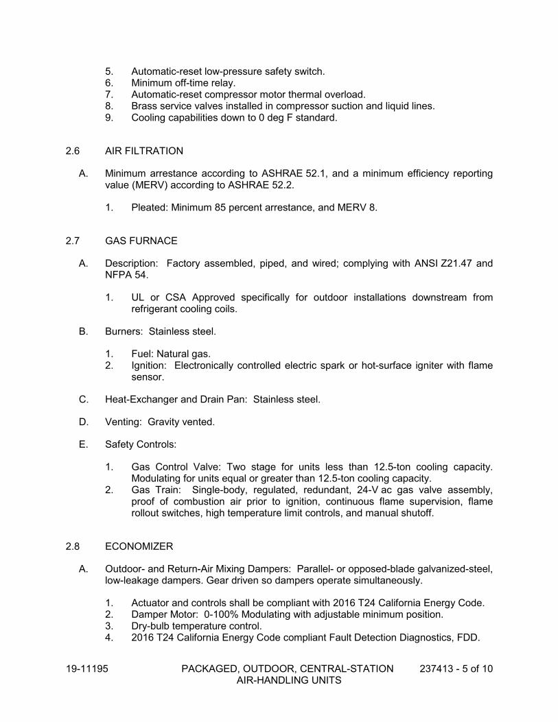
19-11195 PACKAGED, OUTDOOR, CENTRAL-STATION 237413 - 5 of 10 AIR-HANDLING UNITS
5. Automatic-reset low-pressure safety switch. 6. Minimum off-time relay. 7. Automatic-reset compressor motor thermal overload. 8. Brass service valves installed in compressor suction and liquid lines. 9. Cooling capabilities down to 0 deg F standard.
2.6 AIR FILTRATION
A. Minimum arrestance according to ASHRAE 52.1, and a minimum efficiency reporting value (MERV) according to ASHRAE 52.2.
1. Pleated: Minimum 85 percent arrestance, and MERV 8.
2.7 GAS FURNACE
A. Description: Factory assembled, piped, and wired; complying with ANSI Z21.47 and NFPA 54.
1. UL or CSA Approved specifically for outdoor installations downstream from refrigerant cooling coils.
B. Burners: Stainless steel.
1. Fuel: Natural gas. 2. Ignition: Electronically controlled electric spark or hot-surface igniter with flame
sensor.
C. Heat-Exchanger and Drain Pan: Stainless steel.
D. Venting: Gravity vented.
E. Safety Controls:
1. Gas Control Valve: Two stage for units less than 12.5-ton cooling capacity. Modulating for units equal or greater than 12.5-ton cooling capacity.
2. Gas Train: Single-body, regulated, redundant, 24-V ac gas valve assembly, proof of combustion air prior to ignition, continuous flame supervision, flame rollout switches, high temperature limit controls, and manual shutoff.
2.8 ECONOMIZER
A. Outdoor- and Return-Air Mixing Dampers: Parallel- or opposed-blade galvanized-steel, low-leakage dampers. Gear driven so dampers operate simultaneously.
1. Actuator and controls shall be compliant with 2016 T24 California Energy Code. 2. Damper Motor: 0-100% Modulating with adjustable minimum position. 3. Dry-bulb temperature control. 4. 2016 T24 California Energy Code compliant Fault Detection Diagnostics, FDD.

19-11195 PACKAGED, OUTDOOR, CENTRAL-STATION 237413 - 6 of 10 AIR-HANDLING UNITS
5. Relief-Air Damper: Gravity actuated or motorized, as required by ASHRAE/IESNA 90.1-2004, with bird screen and hood.
2.9 ELECTRICAL POWER CONNECTION
A. Provide for single connection of power to unit with unit-mounted disconnect switch accessible from outside unit and control-circuit transformer with built-in overcurrent protection.
2.10 CONTROLS
A. Control control equipment and sequence of operations with schedules on plans and Division 23 Section "Building Automation System."
B. DDC Controller:
1. Microprocessor unit-mounted DDC controller to provide proportional integral room control. Controller shall perform all unit functions by making all heating, cooling and ventilation decisions through resident software logic. Unit shall control staging of compressors, Economizer modulation and CO2 Demand Ventilation Control.
2. Coordinate electronic room temperature sensor with Division 23 Section “Building Automation System”.
3. Controller shall have volatile-memory backup.
4. Safety Control Operation:
a. Smoke Detection Contacts: Stop fan and close outdoor-air damper upon signal from smoke detector.
b. Low-Discharge Temperature: Stop fan and close outdoor-air damper if supply air temperature is less than 40 deg F.
5. Sequence of Operations: Refer to and coordinate with Division 23 Section “Building Automation System”.
C. Interface Requirements for HVAC Instrumentation and Control System:
1. Interface relay for scheduled operation. 2. Interface relay to provide indication of fault at the central workstation and
diagnostic code storage. 3. Provide BACnet or LonWorks compatible interface to building BAS/DDC system
for the following:
a. Adjusting set points. b. Adjust occupied and unoccupied scheduling. c. Monitoring supply fan start, stop, speed and operation status.

19-11195 PACKAGED, OUTDOOR, CENTRAL-STATION 237413 - 7 of 10 AIR-HANDLING UNITS
d. Inquiring data to include economizer damper position, supply- and room-air temperature.
e. Monitoring occupied and unoccupied operations. f. Monitoring variable-frequency drive operation. g. Monitoring compressor status. h. Monitoring unit alarm status. i. Monitoring heating/cooling mode status. j. Monitoring heating stage.
2.11 ACCESSORIES
A. Filter differential pressure switch with sensor tubing on either side of filter. Set for final filter pressure loss.
B. Coil guards of painted, galvanized-steel wire.
PART 3 - EXECUTION
3.1 EXAMINATION
A. Examine substrates, areas, and conditions, with Installer present, for compliance with requirements for installation tolerances and other conditions affecting performance of RTUs.
B. Examine roughing-in for RTUs to verify actual locations of piping and duct connections before equipment installation.
C. Examine roofs for suitable conditions where RTUs will be installed.
D. Proceed with installation only after unsatisfactory conditions have been corrected.
3.2 INSTALLATION
A. Equipment Mounting: Install RTUs on equipment platform using elastomeric pads. Comply with requirements for equipment platforms specified in Division 06 Section "Rough Carpentry."
B. Equipment Platform: Install on roof structure, level and secure, according to AHRI Guideline B. Install RTUs on equipment platforms and coordinate roof penetrations and flashing with roof construction specified in Division 07 Sections. Secure RTUs to equipment platform using elastomeric pads, and secure equipment base to roof framing.
3.3 CONNECTIONS
A. Install condensate drain, minimum connection size, with trap. Route to drain per plans.

19-11195 PACKAGED, OUTDOOR, CENTRAL-STATION 237413 - 8 of 10 AIR-HANDLING UNITS
B. Install piping adjacent to RTUs to allow service and maintenance.
1. Gas Piping: Comply with applicable requirements in Division 22. Connect gas piping to burner, full size of gas train inlet, and connect with union and shutoff valve with sufficient clearance for burner removal and service.
C. Duct installation requirements are specified in other Division 23 Sections. Drawings indicate the general arrangement of ducts. The following are specific connection requirements:
1. Install ducts to termination at top of roof curb. 2. Remove roof decking only as required for passage of ducts. Do not cut out
decking under entire roof curb. 3. Connect supply ducts to RTUs with flexible duct connectors specified in
Division 23 Section "Air Duct Accessories."
3.4 FIELD QUALITY CONTROL
A. Manufacturer's Field Service: Engage a factory-authorized service representative to inspect, test, and adjust components, assemblies, and equipment installations, including connections. Report results in writing.
B. Perform tests and inspections and prepare test reports.
1. Manufacturer's Field Service: Engage a factory-authorized service representative to inspect components, assemblies, and equipment installations, including connections, and to assist in testing. Report results in writing.
C. Tests and Inspections:
1. After installing RTUs and after electrical circuitry has been energized, test units for compliance with requirements.
2. Inspect for and remove shipping bolts, blocks, and tie-down straps. 3. Operational Test: After electrical circuitry has been energized, start units to
confirm proper motor rotation and unit operation. 4. Test and adjust controls and safeties. Replace damaged and malfunctioning
controls and equipment.
D. Remove and replace malfunctioning units and retest as specified above.
3.5 STARTUP SERVICE
A. Engage a factory-authorized service representative to perform startup service.
B. Complete installation and startup checks according to manufacturer's written instructions and do the following:
1. Inspect for visible damage to unit casing. 2. Inspect for visible damage to furnace combustion chamber. 3. Inspect for visible damage to compressor, coils, and fans.

19-11195 PACKAGED, OUTDOOR, CENTRAL-STATION 237413 - 9 of 10 AIR-HANDLING UNITS
4. Inspect internal insulation. 5. Verify that labels are clearly visible. 6. Verify that clearances have been provided for servicing. 7. Verify that controls are connected and operable. 8. Verify that filters are installed. 9. Clean condenser coil and inspect for construction debris. 10. Clean furnace flue and inspect for construction debris. 11. Connect and purge gas line. 12. Remove packing from vibration isolators. 13. Inspect operation of barometric relief dampers. 14. Verify lubrication on fan and motor bearings. 15. Inspect fan-wheel rotation for movement in correct direction without vibration and
binding. 16. Adjust fan belts to proper alignment and tension. 17. Start unit according to manufacturer's written instructions.
a. Start refrigeration system. b. Do not operate below recommended low-ambient temperature. c. Complete startup sheets and attach copy with Contractor's startup report.
18. Inspect and record performance of interlocks and protective devices; verify sequences.
19. Operate unit for an initial period as recommended or required by manufacturer. 20. Perform the following operations for both minimum and maximum firing. Adjust
burner for peak efficiency.
a. Measure gas pressure on manifold. b. Inspect operation of power vents. c. Measure combustion-air temperature at inlet to combustion chamber. d. Measure flue-gas temperature at furnace discharge. e. Perform flue-gas analysis. Measure and record flue-gas carbon dioxide
and oxygen concentration.
21. Adjust and inspect high-temperature limits. 22. Inspect economizer and relief dampers for proper operation. 23. Start refrigeration system and measure and record the following when ambient is
a minimum of 15 deg F above return-air temperature:
a. Coil leaving-air, dry- and wet-bulb temperatures. b. Coil entering-air, dry- and wet-bulb temperatures. c. Outdoor-air, dry-bulb temperature. d. Outdoor-air-coil, discharge-air, dry-bulb temperature.
24. Inspect controls for correct sequencing of heating, mixing dampers, refrigeration, and normal and emergency shutdown.
25. After startup and performance testing and prior to Substantial Completion, replace existing filters with new filters.

19-11195 PACKAGED, OUTDOOR, CENTRAL-STATION 237413 - 10 of 10 AIR-HANDLING UNITS
3.6 CLEANING AND ADJUSTING
A. Occupancy Adjustments: When requested within 12 months of date of Substantial Completion, provide on-site assistance in adjusting system to suit actual occupied conditions. Provide up to two visits to site during other-than-normal occupancy hours for this purpose.
B. After completing system installation and testing, adjusting, and balancing RTU and air-distribution systems, clean filter housings and install new filters.
END OF SECTION

19-11195 SUMMARY OF ELECTRICAL WORK 260000 - 1 of 5
SECTION 260000 SUMMARY OF ELECTRICAL WORK
PART 1 - GENERAL
1.1 SCOPE
A. In general, the Electrical Work described herein consists of the modification of existingelectrical, lighting and signal systems in place and the installation of new electrical,lighting and signal systems equipment. All work shall be completed as directed by theOwner's authorized representative, in accordance with the Contract, Specifications andConstruction Documents listed below.
1. General Conditions of Contract
2. Specifications:
Section Title
260000 Summary of Electrical Work
260100 General Conditions for Electrical Work
260500 Basic Electrical Materials and Methods
260526 Grounding
262413 Switchboards
262416 Panelboards
269500 Electrical Acceptance Tests
3. Electrical Construction Drawings as listed on the Drawing Index of theConstruction Drawing set:
Number Title
E200 Electrical Demolition Plan
E210 Power Plan
E220 Electrical Demolition Roof Plan
E230 Roof Power Plan
E700 Single Line Diagram
E800 Electrical Schedules, Legend, Details, and Notes
B. This Section includes all necessary and required work to complete the construction asindicated in the Drawings, called for by notes or schedules, or specified herein. This workincludes the furnishing of all permits, labor, supervision, services, materials, tools,equipment, testing, transportation and miscellaneous expenses, and the performance ofall operations necessary to or incidental to completion of lawful and operating electricalpower, lighting and signal systems, whether or not specifically mentioned.
C. All work not shown in complete detail shall be installed per the CEC and in conformancewith the best standard practice for the trade. Any deviation from the approved Drawingsshall be submitted in writing to the Engineer and Owner for approval prior to theinstallation of the work in question.
D. This work shall include, but not necessarily be limited to, the following elements:
1. Demolition:

19-11195 SUMMARY OF ELECTRICAL WORK 260000 - 2 of 5
a. De-energize, disconnect and remove electrical feeds to mechanical equipment being removed.
b. De-energize, disconnect and remove electrical service meter and cabinet.
c. De-energize, disconnect and remove electrical feed between service meter and PG&E point of connection.
2. Electrical Service:
a. New electrical service, as shown, complete with underground primary conduit, transformer pad and barriers, splice boxes, and secondary conduit per PG&E requirements.
b. Coordinate with utility company to insure compliance with applicable service standards, specifications, and utility point of connection.
3. Electrical Distribution:
a. Power distribution system, as shown, complete with switchboards, panelboards, conduits, feeders, fittings and related equipment and equipment pads.
b. Trenching, conduits and feeders for electrical power.
4. Grounding
a. Grounding system including installations of ground rods, ufer grounds, and ground rings, as shown. Connections to water and/or gas piping and building steel.
b. Provide the following grounding electrodes at each building, bonded together to form the grounding electrode system:
1) Metal underground water pipe in direct contact with the earth for ten feet or more and electrically continuous to the points of connection of the grounding electrode conductor and the bonding conductors.
2) Concrete encased electrode (Ufer ground) consisting of a minimum of 20 feet of bare copper conductor (size 4 minimum) encased by a minimum of 2 inches of concrete, located within and near the bottom of a concrete foundation or footing that is in direct contact with the earth.
3) Ground rod of copper clad steel, minimum ¾ inch diameter, minimum 10 feet long, driven full length into the earth. If a maximum resistance to ground of 5 ohms cannot be obtained with a single ground rod, provide additional ground rods installed not closer than 6 feet apart until a maximum resistance to ground of 5 ohms is obtained.
c. Testing of grounding system as outlined in Section 269500.
5. Building Electrical and Mechanical Systems:
a. Complete system of branch circuit wiring, conduit and distribution equipment for power.
b. Electrical work associated with mechanical equipment, including conduit, conductor, disconnect switches and motor starters.

19-11195 SUMMARY OF ELECTRICAL WORK 260000 - 3 of 5
c. Furnish roof jacks for the weatherproofing of each electrical conduit penetrating the roof. Roof jacks shall be of the material specified for the specific roofing system and shall be delivered to the general contractor/construction manager for installation by the roofing contractor.
d. Connection to all equipment as furnished by other Sections of these Specifications or as listed on Drawings as furnished by Owner.
6. Each system shall be terminated, tested and calibrated by a factory-authorized installer. This same installer shall terminate and test any peripheral equipment required for the operation of the system.
7. Equipment Connections
a. Provide equipment connections and coordination in accordance with manufacturer’s recommendations and product submittals.
b. Provide equipment connections and disconnect switches as required for the following equipment:
1) Mechanical equipment.
E. Products supplied by Owner (or others, as noted) and installed by Contractor under this Section.
1. None.
F. Products supplied by Contractor but not installed under this Section.
1. None.
G. Work specifically excluded from this Division.
1. Furnishing of motors.
2. Work performed under SECTION 13120, PRE-ENGINEERED FABRICATED STRUCTURES, shall be EXCLUDED from this Section.
H. The following Sections contain requirements that relate to this Section:
1. None
I. It shall be understood that the existing conduit with its wiring is presently active (hot), in operation with its pertinent equipment.
J. It shall be noted that this construction work will be planned and executed during ongoing operation of the facility. Any modifications to the existing equipment currently in operation shall be done during scheduled shutdowns and coordinated with the Owner's authorized representative and facility operating personnel to assure minimum downtime.
K. In order to avoid disruption to facility operations, certain items of work must be completed before other items of work can be started. Contractor shall coordinate with the Owner's authorized representative as to the sequence of construction activities.
L. Drawings showing equipment layout, conduit runs, conduit sizes, number of wires, wire types, wire groupings and size will not be furnished. It shall be the Contractor's responsibility to prepare such drawings in accordance with specifications, project requirements and code to facilitate the installation.

19-11195 SUMMARY OF ELECTRICAL WORK 260000 - 4 of 5
M. Coordinate with the civil engineer to locate the concrete pad and the knock out box in the pad for the high voltage conduits and electrical power circuits.
N. Furnish, install and connect an underground grounding system, specifically mentioned on drawings as part of this contract, including all necessary materials and connections as required by code and/or as shown on the construction drawing.
O. Furnish, install and connect all above grade grounding materials and make aboveground connections of underground cables to equipment and/or structural steel as shown on the construction drawings and as required by code.
P. Size, furnish, install and connect new conduit, conduit fittings, and seal fittings, expansion fittings and supports. This includes above grade as well as underground.
Q. Size, furnish, and install junction, pull and terminal boxes, in accordance to code requirements and as shown on the construction drawings.
R. Size, furnish and install all supports required for conduit installation, supports required for the installation of the equipment furnished by this Contractor and equipment furnished by others but installed by this Contractor.
S. Size and field cut the openings for conduits passing through building walls and/or floors. Close and seal all openings after conduits have been installed and/or removed. Closing shall be compatible with, or of the same material as wall and/or floor.
T. Furnish and install permanent "DANGER - HIGH VOLTAGE" warning signs for the outdoor and indoor switchgear, all unit substations, motor control centers, power distribution panels, and on all doors of all electrical equipment rooms, fenced yards, etc.
U. Furnish and install markers indicating voltage levels (e.g., 12.47 KV, 277/480V, 120/208V, etc.) for all of the electrical equipment such as motor control centers, local lighting panels, lighting transformers, power panels, switchboards, etc....
V. Furnish and install new nameplates per specifications on new motor control centers, motors and on all local control stations, control panels, disconnect switches, push button stations, instrument devices, etc.
W. Furnish and install wire tags in accordance with the specifications indicating wire number as shown on electrical schematics, one line, three line diagrams and specifications.
X. Furnish, install and connect all power, control and instrumentation cable, including all necessary cable lugs, connectors and terminations.
Y. Perform all testing per the Specifications (including generator cables) and report to Owner's field representative in a timely manner so as not to impede the scheduled completion of the Contract.
Z. Furnish all material, labor and testing equipment necessary to check out and test the complete power distribution, control and pneumatic systems for all process and utility equipment in strict accordance with specifications. This shall include check out/start up of systems and/or equipment as directed by Owner.
AA. Prime paint all uncoated carbon steel items furnished by Contractor.

19-11195 SUMMARY OF ELECTRICAL WORK 260000 - 5 of 5
BB. Energize low voltage services after testing equipment and wiring in accordance with manufacturer instructions and specifications.
CC. Provide four ¾” 10 ft copper ground rods, Cadweld the ground rods to the bare copper #4/0 ground ring. Install a ground rod for each of the generators. Connect ground cable to existing grounding loop at the facility
PART 2 - NOT USED
PART 3 - NOT USED
END OF SECTION 260000


19-11195 GENERAL CONDITIONS 260100 - 1 of 10 FOR ELECTRICAL WORK
SECTION 260100 GENERAL CONDITIONS FOR ELECTRICAL WORK
PART 1 - GENERAL
1.1 GENERAL CONDITIONS
A. The general provisions of the Contract, including General Conditions and Specification Division 01, General Requirements, shall form a part of this Section, with the same force and effect as though repeated here. The provisions of this Section shall apply to all of the following Sections of Divisions 26-28 of these Specifications and shall be considered a part of these Sections.
1.2 QUALITY ASSURANCE
A. All work and materials shall fully comply with current rules and regulations of all applicable codes. Nothing in these Drawings or Specifications shall be interpreted as to permit any work not in compliance with these codes. Where work is detailed and/or specified to a more restrictive standard or higher requirement, that standard or requirement shall govern such work. Applicable codes include, but are not limited to, the following:
1. California Code of Regulations (CCR)
a. Title 8, Industrial Relations
b. Title 17, Public Health
c. Title 24, Building Standards
2. 2016 California Building Code.
3. 2016 California Fire Code.
4. 2016 California Electrical Code.
5. Local Codes.
B. All electrical components, devices and accessories shall be listed with Underwriters Laboratories, Inc. (or other testing agency acceptable to authorities having jurisdiction), shall meet their requirements, shall bear their label wherever standards have been established and label service is regularly furnished by that agency, and shall be marked for intended use.
1.3 PERMITS, FEES AND TAXES
A. The Contractor shall secure all necessary permits and pay all required fees and taxes. He shall notify the proper authorities and have the work inspected and tested as required by jurisdictional requirements, pay all charges in connection therewith, and shall present to the Owner properly signed certificates of inspection. Acceptance of the work will not be considered until such certificates have been delivered.
B. The Owner shall pay all utility company charges related to the new services. This shall include any required street lighting charges.

19-11195 GENERAL CONDITIONS 260100 - 2 of 10 FOR ELECTRICAL WORK
1.4 TEMPORARY UTILITIES
A. The Contractor shall fulfill utility requirements for and pay all one-time and monthly charges for temporary construction utility usage.
B. There is no existing onsite power available to the Contractor for construction. The Contractor shall schedule his work such that the Medium and Low Voltage Electrical work is completed prior to needing onsite electrical power for jobsite trailers and/or construction equipment. The Contractor shall then use the Medium and Low Voltage power distribution system to provide construction power. The Contractor shall supply any supplemental temporary facilities required to provide construction power to the site (i.e. transformers, panels, outlet boxes).
1.5 EXISTING CONDITIONS
A. The Contractor shall carefully examine the site and existing buildings, compare them with Drawings and Specifications, and shall have satisfied himself as to the conditions to be encountered during the performance of the work. No subsequent allowance shall be made on his behalf for any additional expense he may incur due to failure or neglect of Contractor to examine site and to include existing conditions in bid.
B. Any work done as an addition, expansion, or remodel of an existing system shall be compatible with that system.
C. The Contractor shall examine all record drawings made available by the Owner to locate existing underground systems, utilities, conduits, and pipes prior to installing the electrical distribution system. The Contractor shall also examine the site for possible locations of sprinkler pipes. Any damage done to the existing systems during the course of the electrical work, whose locations could be reasonably determined, shall be repaired to the satisfaction of the Owner and the utility or agency involved, at the expense of the Contractor.
1.6 CONDUCT OF THE WORK
A. The Contractor shall maintain on the job a competent foreman or a superintendent at all times to superintend the Work.
1.7 INTERPRETATION OF DRAWINGS AND SPECIFICATIONS
A. The Engineer’s decision will be final on interpretation of the Drawings and Specifications. Whenever the words “AS MAY BE DIRECTED”, “SUITABLE”, or “APPROVED EQUAL”, or other words of similar intent and meaning are used, implying that judgment is to be exercised, it is understood that it is in reference to the judgement of the Engineer.
1.8 SUBMITTALS
A. See Specification Section 013300, SUBMITTAL PROCEDURES, for additional information and requirements.
B. Shop Drawings and Product Data

19-11195 GENERAL CONDITIONS 260100 - 3 of 10 FOR ELECTRICAL WORK
1. In addition to the provisions of Specification Section 013300, SUBMITTAL PROCEDURES, all Shop Drawings and Product Data shall comply with the following requirements:
a. The Contractor shall submit for review, complete sets of Shop Drawings and Product Data brochures for materials and equipment as required by each section of the Specifications.
b. All Shop Drawings and Product Data shall be submitted at one time in a neat and orderly fashion in a suitable binder with a Title Sheet including Project, Engineer and Contractor, Table of Contents, and indexed tabs dividing each group of materials or item of equipment. The Specification paragraph number for which they are proposed shall identify all items. The mark number as indicated on Drawings shall also identify all equipment and fixtures.
c. Shop Drawings and Product Data submittal shall include manufacturer’s name and catalog numbers, dimensions, loads, and all other characteristics and accessories as listed in the Specifications or on the Drawings. All loads, characteristics, and accessories called for in the Specifications or on the Drawings shall be highlighted, circled or underlined on the Shop Drawings and Product Data. Descriptive literature shall be current factory brochures and submittal sheets.
d. FAX submittals are not acceptable.
e. Material or equipment shall not be ordered or installed until the Engineer processes the written review. Any item omitted from the submittal shall be provided as specified without substitution.
f. Prior to submission of the Shop Drawings and Project Data, Contractor shall review and certify that they meet the requirements of the Contract Documents.
g. A minimum period of two weeks, exclusive of transmittal time, will be required each time Shop Drawings and/or Product Data are submitted or resubmitted for review. The Contractor shall consider this time when scheduling a submittal date.
C. Submittal Review
1. Submittals will be reviewed for general conformance with the design concept, but this review does not guarantee quantity shown, nor does it supersede the responsibility of the Contractor to provide all materials, equipment and installation in accordance with the Drawings and Specifications.
2. The Contractor shall agree that Shop Drawings and Product Data submittals processed by the Engineer are not Change Orders and that the purpose of Shop Drawings and Product Data submittals by the Contractor is to demonstrate to the Engineer that the Contractor understands the design concept. The Contractor demonstrates his understanding by indicating which equipment and material he intends to furnish and install and by detailing the fabrication and installation methods he intends to use.
3. It shall be clearly understood that the noting of some errors, but the overlooking of others, does not grant the Contractor permission to proceed in error or in conflict with Contract Documents. The Contractor shall agree that if deviations, discrepancies or conflicts between Shop Drawings and Design Drawings and Specifications are discovered either prior to or after Shop Drawing submittals are

19-11195 GENERAL CONDITIONS 260100 - 4 of 10 FOR ELECTRICAL WORK
processed by the Engineer, the Design Drawings and Specifications shall control and shall be followed.
4. If a resubmittal is required, submit a complete copy of the Engineer’s review letter requiring such with the resubmittal.
D. Substitutions
1. See Specification Section 012500, SUBSTITUTION PROCEDURES, for additional information and requirements.
2. In addition to the provisions of Specification Section 012500, SUBSTITUTION PROCEDURES, Substitutions shall comply with the following requirements:
a. Manufacturers, model numbers and other pertinent information listed in the Specifications or on the Drawings are intended to establish minimum standards of performance, function and quality. Unless otherwise noted, the Contractor may submit equivalent compatible UL-listed equipment from other manufacturers for review, as long as the minimum standards are met.
b. Calculations and other detailed data indicating how the item was selected shall be included for items that are not specified. Data must be complete enough to permit detailed comparison of every significant feature, function, performance, and quality characteristic that is specified, scheduled or detailed. The comparison must prove that the substituted item equals or exceeds the requirements of the specified item.
c. The Contractor shall assume full responsibility that substituted items or procedures will meet the Specification and job requirements and shall be responsible for the cost of redesign and modifications to the work caused by these items.
d. At the Engineer’s request, the Contractor shall furnish locations where equipment similar to the substituted equipment is installed and operating along with the user’s phone numbers and contact person. Satisfactory operation and service history will be considered in the acceptance or rejection of the proposed substitution.
E. Record Drawings
1. See Specification Section 017839, PROJECT RECORD DOCUMENTS, for additional information and requirements.
2. In addition to the provisions of Specification Section 017839, PROJECT RECORD DOCUMENTS, Record Drawings shall comply with the following requirements:
a. At the beginning of the Project, one print of each applicable Drawing will be issued to the Contractor specifically for use in preparing Record Drawings. As the work progresses, the Contractor shall maintain a record of all deviations in the work from that indicated on the Drawings. Final locations of all underground work shall be recorded by depth from finished grade and by offset distance from permanent surface structures, e.g. building, curbs, walks. The original Drawings will be made available to the Contractor, from which he shall have made, a set of reproducible Drawings. The Contractor shall then transfer the changes, notations, etc. from the marked-up prints to the reproducible Drawings. The Record Drawings (marked-up prints and reproducibles) shall be submitted to the

19-11195 GENERAL CONDITIONS 260100 - 5 of 10 FOR ELECTRICAL WORK
Engineer for review, after first securing the Inspector’s verification by signature.
F. Operations and Maintenance Instructions
1. See Specification Section 017823, OPERATION AND MAINTENANCE DATA, for additional information and requirements.
2. In addition to the provisions of Specification Section 017823, OPERATION AND MAINTENANCE DATA Operations and Maintenance Instructions shall comply with the following requirements:
a. Three copies of Operation and Maintenance Instructions and Wiring Diagrams for all equipment shall be submitted to the Engineer. All instructions shall be clearly identified by marking them with the same designation as the equipment item to which they apply (e.g. UPS-1). All Wiring Diagrams shall agree with reviewed Shop Drawings and indicate the exact field installation.
b. All instructions shall be submitted at the same time and shall be bound in a suitable binder with tabs dividing each type of equipment (e.g. MCC, UPS, etc.). Each binder shall be labeled indicating “Operating and Maintenance Instructions, Project Title, Contractor, Date” and shall have a Table of Contents listing all items included.
c. The Contractor shall verbally instruct the Owner’s maintenance staff in the operation and maintenance of all equipment and systems. The Engineer’s office shall be notified 48 hours prior to this meeting.
d. The Contractor shall prepare a letter indicating that all Operation and Maintenance Instructions (printed and verbal) have been given to the Owner, to the Owner’s satisfaction. This letter shall be acknowledged (signed) by the Owner and submitted to the Engineer.
1.9 COORDINATION
A. See Specification Section 013113, PROJECT MANAGEMENT AND COORDINATION, for additional information and requirements.
B. Electrical Drawings are essentially diagrammatic, unless specifically dimensioned. Some work may be shown offset for clarity. The actual locations of all materials, conduits, fixtures, supports, etc. shall be carefully planned prior to installation of any work in order to avoid all interferences with each other, or with architectural, civil, mechanical, plumbing, structural or other elements.
C. While the size and location of equipment are shown to scale wherever possible, all dimensions and conduit/conductor data shall be verified in the field.
D. Where the work requires connections to be made to equipment furnished and set in place by others, the Contractor shall obtain exact rough-in dimensions from the manufacturer of such equipment and he shall install the connections in a neat and workmanlike manner.
E. If discrepancies are discovered between Drawings and Specifications requirements, the more stringent requirement shall apply.
F. All conflicts shall be called to the attention of the Architect and the Engineer prior to the installation of any work or the ordering of any equipment.

19-11195 GENERAL CONDITIONS 260100 - 6 of 10 FOR ELECTRICAL WORK
G. No work shall be prefabricated or installed prior to this coordination. No additional compensation will be considered to the Contractor for any prefabrication or installation performed prior to this coordination.
1.10 SCHEDULING
A. All work shall be scheduled subject to the review of the Architect, Engineer and the Owner. No work shall interfere with the operation of the existing facilities on or adjacent to the site. The Contractor shall have at all times, as conditions permit, a sufficient force of workmen and quantity of materials to install the work for which contracted, as rapidly as possible consistent with good work, and shall cause no delay to other Contractors engaged upon this project or to the Owner.
1.11 WARRANTY
A. See Specification Section 017836, WARRANTIES, for additional information and requirements.
B. Guarantee shall be in accordance with the General Conditions. These Specifications may extend the period of the guarantee for certain items. Where such extension are called for, or where items are normally provided with guarantee periods in excess of that called for in the General Conditions, the Certificate of Guarantee shall be furnished to the Owner through the Engineer.
C. Contractor shall deliver to the Owner a written guarantee on all workmanship, materials and equipment for a period of one (1) year from the date of acceptance by the Owner. Any work found to be faulty during that period of time shall be corrected at once, upon written notification, at the expense of the Contractor. This shall include repair or replacement of the premises that may be damaged as a result of faulty work and materials furnished.
PART 2 - PRODUCTS
2.1 MATERIALS AND EQUIPMENT
A. Materials and equipment shall be new unless otherwise noted.
B. Materials and equipment of a given type shall be by the same manufacturer.
C. Materials and equipment shall be covered or otherwise protected during construction as required to maintain the material and equipment in new factory condition until project acceptance. Upon completion of work and prior to final inspection, Contractor shall thoroughly clean all exposed fixtures, trim and equipment, and shall leave the entire installation in neat, clean, and useable condition. Materials and equipment shall be free of dents, scratches, marks, shipping tags, and all defacing features at time of project acceptance.
D. The Contractor shall order materials and equipment in a timely manner to prevent any delay in the construction schedule, and he shall bear any penalty by vendors to meet schedules.

19-11195 GENERAL CONDITIONS 260100 - 7 of 10 FOR ELECTRICAL WORK
E. Verify all dimensional information to ensure proper clearance for installation of equipment. Check all materials and equipment after arrival on the jobsite and verify compliance with the Contract Documents.
PART 3 - EXECUTION
3.1 DEMOLITION
A. The Contractor shall protect existing electrical equipment and installations that are not indicated to be removed. If damaged or disturbed in the course of the Work, remove damaged portions and install new products of equal capacity, quality, and functionality.
B. Exposed electrical equipment and installations, indicated to be demolished, shall be removed in their entirety.
C. Buried raceway and wiring, indicated to be abandoned in place, shall be cut 2 inches below the surface of adjacent construction and removed in its entirety. Raceways abandoned in place shall be capped and disturbed surfaces shall be patched to match existing finish.
D. Demolished material shall be removed from Project site.
E. Components indicated for relocation shall be removed, stored, cleaned, reinstalled, reconnected, and made operational.
3.2 CUTTING AND PATCHING
A. The Contractor shall perform all cutting and drilling, or other work, required to provide openings in walls, ceilings, floors, footings, foundations or other structures necessary to accomplish work under this Specification Division. The cutting shall be performed by skilled mechanics of the trades involved.
B. Cutting or coring shall not impair the strength of the structure. Any damage resulting from this work shall be repaired at the Contractor’s expense to the satisfaction of the Architect.
C. Wherever possible, work shall be done in a concealed and neat workmanlike manner requiring the least amount of cutting of studs, plates and woodwork. Such cutting or notching is allowed only after consultation with and by permission of the Engineer.
D. The Contractor shall repair and refinish disturbed finish materials and other surfaces to accurately match adjacent undisturbed new or existing structures and surfaces and shall install new fireproofing where existing fire-stopping has been disturbed. The repair and refinishing of materials and other surfaces shall be by skilled mechanics of the trades involved.
E. All cuts are to be clean with no chipping. Where chipping occurs as a result of work in a cut area, a new clean cut shall be made immediately prior to patching.
3.3 EXCAVATION AND BACKFILL

19-11195 GENERAL CONDITIONS 260100 - 8 of 10 FOR ELECTRICAL WORK
A. The Contractor shall provide excavation and backfilling required to complete work detailed in the Drawings and Specifications. Unless otherwise noted, minimum earth cover above top of conduit outside building walls shall be 24”, not including base and paving in paved areas.
B. The location of all underground facilities shall be verified with the Owner and utility companies prior to the commencement of any excavation.
C. The Contractor shall contact Underground Service Alert (USA), at 1-800-642-2444, ten (10) days prior to doing any excavation or trenching, and shall advise USA of the work schedule and comply with their requirements.
D. The Contractor shall notify the owner 72 hours prior to any excavation.
E. Provide all shoring required by site conditions. Where over-excavation occurs, provide compacted sand backfill. Where groundwater is encountered, remove to keep excavation dry, using well points and pumps as required.
F. The conduit shall be laid on firm soil cut true and even to afford bearing for the full length of the barrel of the conduit.
G. When the bottom uncovered at sub-grade is soft and, in the opinion of the Engineer, cannot support the conduit, a further depth shall be excavated and refilled to conduit foundation grade as required by the Engineer.
H. Backfill (where concrete encasement is not required):
1. Material 3” below, 3” around, and to 6” above conduit shall be sand. Place carefully around and on top of conduit, taking care not to disturb conduit. Consolidate with vibrator.
2. Material from 6” Above Conduit to Grade shall be sandy or silty loam, free of lumps, laid in 6” layers, uniformly mixed to proper moisture and compacted to required density. If backfill is determined to be suitable and required compaction is demonstrated by laboratory test, water compaction in 6” layers may be used, subject to review by Engineer.
I. No excavation below the level of, or adjacent to, foundations of footings shall be made except in a manner approved by the Structural Engineer.
J. Compaction
1. Prior to compaction, moisten or aerate each layer as necessary to provide optimum moisture content. Compact each layer to required percentage of maximum dry density or relative dry density for each area classification. Do not place backfill or fill material on surfaces that are muddy, frozen, or contain frost or ice.
2. Under Structures, Building Slabs, Walkways, and Steps, compact top 6” of sub-grade and each layer of backfill or fill material at 92% maximum relative compaction. Compact upper 2’ of backfill in utility trenches or other excavations to 92% minimum relative compaction.
3. In Lawns and Unpaved Areas, compact top 6” of sub-grade material to 85% relative compaction.

19-11195 GENERAL CONDITIONS 260100 - 9 of 10 FOR ELECTRICAL WORK
4. Under Pavement, compact top 8” of sub-grade immediately beneath the base course at 95% minimum relative compaction.
3.4 CONCRETE EQUIPMENT BASES
A. The Contractor shall provide a concrete equipment base for each piece of electrical equipment required to have a base as shown in the Drawings, Notes and Details.
B. Concrete equipment bases shall be 6” high concrete, 3500PSI strength, unless otherwise noted. Base shall extend 6” beyond the largest dimensions of the equipment, unless otherwise noted. The top edge of the base shall have a ¾” chamfer. The base shall have #4 reinforcing bars at 12” on center, each way, located at the mid-depth of the base.
C. If the base is not poured at the same time as the floor slab with base rebar tied to floor rebar, the base shall be anchored to the floor slab per the following criteria:
1. Drill 1” diameter, 4” deep hole in floor.
2. Fill hole with Simpson SET Epoxy then insert 8” long, #4 rebar into hole. Tie this rebar to that required for the equipment base.
3. Provide a minimum of 4 of these anchors per base but no more than 4 feet apart in either direction.
4. Anchor points shall be 12” from the edge of the base.
D. Concrete anchors shall be steel bolts with expansion anchors requiring a drilled hole. Powder-driven anchors are not acceptable. Minimum concrete embedment shall be 4.5 diameters but not less than manufacturer’s requirements for minimum strength. Minimum spacing shall be 10 diameters center-to-center and 5 diameters center to edge of concrete but not less than manufacturer’s requirements for minimum strength. Maximum allowable stresses for tension and shear shall be 80% of the ICC-ES test report values.
E. Where applicable, concrete structures shall be submitted to the serving utility for their approval prior to installation.
3.5 SEISMIC ANCHORAGE AND BRACING
A. Equipment Anchorage
1. All electrical equipment and components shall be anchored and installed per the details on the approved construction documents. Where no detail is indicated, the following components shall be anchored or braced to meet the force and displacements requirements prescribed in the 2016 CBC, Sections 1616A.1.18 through 1616A.1.26. and ASCE 7-10 Chapter 13, 26, and 30:
a. All permanent equipment and components
b. Temporary or movable equipment that is permanently attached (e.g. hard wired) to building utility electrical service.
c. Movable equipment which is stationed in one place for more than 8 hours and heavier than 400 pounds are required to be anchored with temporary attachments.

19-11195 GENERAL CONDITIONS 260100 - 10 of 10 FOR ELECTRICAL WORK
2. The attachment of the following electrical components shall be positivelyattached to the structure, but need not be detailed on the plans. Thesecomponents shall have flexible connections provided between the componentsand associated conduit.
a. Components weighting less than 400 pounds and have a center of masslocated 4 feet or less above the adjacent floor or roof level that directlysupport the components.
b. Components weighting less than 20 pounds, or in the case of distributedsystems, less than 5 pounds per foot, which are suspended from a roofor floor or hung from a wall.
For those elements that do not require details on the approved drawings, the installation shall be subject to the approval of the Structural Engineer of Record. The project inspector will verify that all components and equipment have been anchored in accordance with above requirements.
B. Electrical Distribution System Bracing
1. Electrical distribution systems shall be braced to comply with the forces anddisplacements prescribed in ASCE 7-10 Section 13.3 as defined in ASCE 7-10Section 13.6.8, 13.6.7, 13.6.5.6, and 2016 CBC, Sections 1616A.1.23,1616A.1.24, 1616A.1.25, and 1616A.1.26.
2. The bracing and attachments to the structure shall be detailed on the approveddrawings or they shall comply with one of the OSHPD Pre-Approvals as modifiedto satisfy anchorage requirements of ACI 318.
3. Copies of the manual shall be available on the jobsite prior to the start of hangingand bracing of the electrical distribution systems.
4. The Structural Engineer of Record shall verify the adequacy of the structure tosupport the hanger and brace loads.
3.6 CLEANING AND PROTECTION
A. The Contractor shall, progressively and at completion of the job, thoroughly clean all ofhis work including outlets, fittings, and devices, and inspect exposed finishes. TheContractor shall remove all burrs, dirt, grease, paint spots, stains, labels, tags, rust,foreign material, and construction debris resulting from his work.
B. The Contractor shall protect equipment and installations and maintain conditions toensure that coatings, finishes, and cabinets are without damage or deterioration at timeof Substantial Completion.
END OF SECTION 260100

19-11195 BASIC ELECTRICAL MATERIALS AND METHODS 260500 - 1 of 23
SECTION 260500 BASIC ELECTRICAL MATERIALS AND METHODS
PART 1 - GENERAL
1.1 SCOPE
A. See Section 260000
1.2 STANDARDS
A. NEMA 250 Standard for Enclosures for Electrical Equipment (1000 Volts Maximum)
PART 2 - PRODUCTS
2.1 CONCRETE PADS, PULL BOXES AND MANHOLES
A. At the Contractor’s option, he shall provide cast-in-place or pre-cast structures.
B. Concrete Forms and Reinforcement Materials shall be as specified in Division 03 Section “Cast-in-Place Concrete”.
C. Concrete shall be 2500-psi, 28-day compressive strength as specified in Division 03 Section “Cast-in-Place concrete”.
2.2 RACEWAYS AND FITTINGS
A. Galvanized rigid steel conduit (GRC) shall meet ANSI C80.1, and be heavy wall, hot dipped galvanized inside and out, with threaded ends, for use with threaded type fittings.
B. Galvanized intermediate metallic conduit (IMC) shall meet ANSI C80.6, be zinc-coated steel and have threaded fittings.
C. Galvanized electrical metallic tubing (EMT) shall meet ANSI C80.3, and be continuous, seamless steel tubing, galvanized or sherardized on exterior, coated on interior with smooth hard finish of lacquer, varnish or enamel, with steel set-screw, steel compression or die-cast compression type fittings. Provide concrete-tight type compression fittings where required and rain-tight wet location listed compression fittings for outdoor locations.
D. Rigid non-metallic conduit (RNC) shall meet NEMA TC 2, be Schedule 40 PVC, suitable
for 90°C, with solvent cemented type NEMA TC3 fittings.

19-11195 BASIC ELECTRICAL MATERIALS AND METHODS 260500 - 2 of 23
E. Flexible metallic conduit (FMC) shall be single strip, continuous, flexible interlocked double-wrapped steel, hot dip galvanized inside and out forming smooth internal wiring channel, with steel, compression type fittings.
F. Liquid-tight flexible metallic conduit (LFMC) shall be same as FMC except with inert sunlight-resistant, mineral-oil-resistant watertight plastic outer jacket. Fittings shall be cast malleable iron body and gland nut, cadmium plated with one-piece brass grounding bushings threaded to interior of conduit. Spiral molded vinyl-sealing ring between gland nut and bushing and nylon-insulated throat.
G. All raceway fittings shall be specifically designed for the raceway type with which used.
2.3 SURFACE MOUNTED RACEWAY
A. Surface Mounted Nonmetallic Raceways and system components shall be composed of U.L. Listed materials and exhibit nonflammable self-extinguishing characteristics. Larger (2 and 3 channel non-metallic raceways) shall be UL Listed under File Nos. E90378 Guide RJTX and E90377 Guide RJYT, respectively. Raceways shall be tested to UL94V-0, or equivalent.
B. Surface Mounted Nonmetallic Raceway shall be a two-piece design with a base and snap-on cover(s). The raceway base shall accept either a single cover that spans the entire base or two individual covers which together cover the base and allow independent access to services.
C. Surface Mounted Nonmetallic Raceway shall be available with two or three wiring channels separated by integral barriers. One channel must be large enough to accept standard power and communication devices without restricting capacity of the adjacent channel. The raceway base and cover shall be manufactured of rigid PVC compound, available in ivory or white.
D. Device brackets shall be available for mounting standard devices in-line or offset from the raceway. A device bracket shall provide up to three single-gang openings at one location. Faceplates shall match raceway and fit flush in the device plate. They shall be manufactured of rigid PVC compound.
E. The raceway manufacturer will provide a complete line of connectivity outlets and modular inserts for UTP, STP (150 ohm), fiber optic, coaxial and other cabling types with faceplates and bezels to facilitate mounting. A complete line of preprinted station and port identification labels, snap-in icon buttons, as well as write-on station identification labels shall be available.
F. A complete line of full capacity corner elbows and tee fittings must be available to maintain a controlled 2" cable bend radius which meets the specifications for Fiber Optic and UTP/STP cabling and exceeds the TIA / EIA 569-A requirements for communications pathways. They shall be manufactured of a rigid PVC compound.
G. A full complement of fittings must be available including, but not limited to tees, entrance fittings, cover clips, and end caps. They shall be manufactured of a rigid PVC compound. The fittings shall have a matte texture, in ivory or white colors to match the base and cover. They shall overlap the cover and base to hide uneven cuts. All fittings shall be

19-11195 BASIC ELECTRICAL MATERIALS AND METHODS 260500 - 3 of 23
supplied with a base where applicable to eliminate mitering. Transition fittings shall be available to adapt to other raceways.
H. Surface Mounted Nonmetallic Raceway shall be multi-channel 5400 Series by the Wiremold Company, or equal.
2.4 CONDUCTORS
A. All conductors shall be delivered to the site in their original unbroken packages, plainly marked or tagged with UL labels, size, type of wire, type of insulation, name of the manufacturing company and trade name of the wire.
B. All conductors shall be minimum of 98% conductivity soft drawn copper. Conductors #8 AWG and larger shall be stranded type “THWN/THHN”, 600 Volt insulation. Conductors #10 AWG and smaller shall be solid copper “THWN/THHN”, 600 Volt insulation.
C. Insulation shall be Thermoplastic Type rated at 75 degrees C. minimum.
2.5 PULL BOXES AND WIREWAYS
A. Pullboxes and Enclosures for outdoor use shall be NEMA 250, Type 3R or Type 4, unless otherwise noted.
B. Pullboxes and Enclosures for indoor use shall be NEMA 250, Type 1, unless otherwise noted.
C. Wireways shall be constructed in accordance with UL 870 for wireways, auxiliary gutters and associated fittings. Every component including lengths, connectors and fittings shall be UL Listed.
D. Wireways and auxiliary gutters shall have continuous removable cover secured with screws and keyhole slots. Hinged cover shall be provided where installed above suspended ceiling.
E. Fabricated sheet steel pull boxes shall be installed only in dry, protected locations and shall be furnished with knockouts and removable screw cover. Box shall be finished with one coat of zinc chromate and a coat of primer sealer and where exposed to public view shall be painted to match the surrounding surface.
F. Weatherproof sheet steel pull boxes shall be fabricated of code gauge galvanized sheet steel with two coats of rust resistant finish and shall be furnished with gasket and made completely weathertight.
2.6 WIRING DEVICES AND MATERIALS
A. Outlet Boxes shall meet NEMA OS1 and be galvanized code gauge steel. Boxes in masonry shall be square cornered. Boxes exposed to weather or in wet locations shall be Type FD cast metal with external threaded hubs and gasketed cover and shall meet NEMA FB1.

19-11195 BASIC ELECTRICAL MATERIALS AND METHODS 260500 - 4 of 23
B. Outlet box extensions shall be U.L. listed and shall be attached to box with threaded metal screws. “Flash Guards” are not permitted to be used as box extensions.
C. Approved manufacturers of metal boxes are Circle AW, Crouse-Hinds, Steel City or equal.
D. Receptacles:
1. GFCI Receptacles:
a. GFCI receptacles shall be duplex, feed-through type, with integral NEMA WD 6, Configuration 5-20R duplex receptacle arranged to protect connected downstream receptacles on same circuit. Design units for installation in a 2-3/4-inch deep outlet box without an adapter.
b. Duplex GFCI receptacles shall be Hubbell or Leviton #GF5352 to match regular duplex receptacle.
2. Required Weather-Resistant Receptacles: All 15- and 20-ampere, 125- and 250-volt non-locking type receptacles located outdoors and in damp and wet locations shall be listed weather-resistant type.
3. Other Receptacles: Other receptacles shall match the plug configuration and ratings required for the utilization equipment that is served.
E. Device cover plates shall be provided and installed at all wiring devices, switches, outlets, and similar applications, and shall be as directed by architect. Pull boxes and junction boxes to which no fixture is to be attached shall be fitted with blank cover plates painted to match surrounding. All cover plates installed on rated walls shall be brushed stainless steel. Cover plates installed at switches used for lighting control in all multiple occupant restrooms, all hallways and corridors, and in other locations where lockable cover plates are indicated on the Drawings shall be the dustproof locking stainless steel cover Legrand model WP26-L.
2.7 PANELBOARDS
A. Furnish panelboards shown on plans and described herein. All cans shall be a minimum of 20” wide and 5.75” deep unless otherwise shown. They shall be totally flat or equal with flush keyed locks.
B. Fronts shall be cold rolled sheet steel painted with ANSI 61 gray enamel over a rust inhibitor. They shall be equipped with door, flush hinges, and flush proper cylinder tumbler lock, metal circuit card holder, and quarter turn adjustable trim clamps. Panel locks shall be keyed alike.
C. Panel shall consist of reinforced corrosion resistant galvanized sheet steel frame with silver plated copper bus bars and circuit breakers properly supported to prevent vibration breakage in handling. All terminals shall be solderless type suitable for specified conductors of size indicated.
D. Neutral bus shall be full size. Neutral bus shall be 200% rated when supplied from a double neutral feeder. Provide an equipment ground bus in each panelboard. In addition

19-11195 BASIC ELECTRICAL MATERIALS AND METHODS 260500 - 5 of 23
to the equipment ground bus, provide an isolated ground bus when supplied from a feeder which includes an isolated grounding conductor.
E. Branch circuit breakers shall be molded case, bolt-on, and fully interchangeable without disturbing adjacent units. All 2-pole and 3-pole breakers shall have common trips.
F. Branch panelboards and overcurrent protection devices shall have a minimum short circuit rating of 10,000 RMS symmetrical AIC (120/208V).
G. Distribution panelboards and overcurrent protection devices shall have a minimum short circuit rating of 42,000 RMS symmetrical AIC (120/208V).
H. All Panelboards shall be fully rated as shown on Drawings; series-rating shall not be allowed.
I. Panelboards shall bear an Arc-Flash Hazard Warning label in accordance with CEC Article 110.16.
J. Breakers for mechanical equipment shall be HACR type.
K. All spaces shall have hardware.
2.8 DISCONNECTING DEVICES
A. Disconnecting devices shall be provided as shown and/or as required by CEC.
B. Disconnect switches shall be 250V or 600V class, rated heavy-duty, horsepower rated, quick-make, quick-break, dead-front type and provided with proper number of poles.
C. Disconnect Switches shall be self contained in a NEMA 1 gasketed enclosure (NEMA 3R where installed outdoors) and externally operable from the front.
D. Fusible disconnect switches shall be equipped with rejection type clips suitable for UL Class R fuses up to 600A and suitable for UL Class L fuses above 600A. Fuse interrupting rating shall be 200,000 RMS symmetrical amperes.
E. Circuit breakers utilized as disconnecting devices shall comply with the requirements stated in other articles of this section and CEC.
2.9 FUSES
A. Subject to compliance with requirements, provide products by one of the following manufacturers:
1. Bussman
2. Gould Shawmut
3. Littlefuse.

19-11195 BASIC ELECTRICAL MATERIALS AND METHODS 260500 - 6 of 23
B. Fuses 600 amperes and below shall be UL Class RK1, 200,000 RMS symmetrical amperes interrupting rating.
C. Fuses 601 amperes through 4000 amperes shall be UL Class L, 200,000 RMS symmetrical amperes interrupting rating.
2.10 SUPPORTING DEVICES
A. Supporting devices shall be constructed of cold-formed steel, with a corrosion-resistant coating acceptable to authorities having jurisdiction.
B. Metal items for use outdoors or in damp locations shall be hot-dipped galvanized steel.
C. Slotted-steel channel supports shall have flanged edges turned toward the web, and 9/16-inch diameter slotted holes at a maximum of 2 inches on center, in the web.
1. Channel thickness shall be selected to suit structural loading.
2. Fittings and accessories shall be products of the same manufacturer as the channel supports.
D. Raceway and cable supports shall be manufactured clevis hangers, riser clamps, straps, threaded C-clamps with retainers, ceiling trapeze hangers, wall brackets, and spring-steel clamps or click-type hangers.
E. Pipe sleeves shall be ASTM A 53, Type E, Grade A, Schedule 40, galvanized steel, with plain ends.
F. Cable supports for vertical conduit shall be a factory-fabricated assembly consisting of threaded body and insulating wedging plug for non-armored electrical cables in riser conduits. Plugs shall have number and size of conductor gripping holes as required to suit individual risers. Body shall be constructed of malleable-iron casting with hot-dip galvanized finish.
G. Concrete anchors shall be steel bolts with expansion anchors requiring a drilled hole. Powder driven anchors are not acceptable.
H. Toggle bolts shall be all-steel springhead type.
2.11 ELECTRICAL IDENTIFICATION
A. Identification devices shall be a single type of product for each application category. Colors shall be as prescribed by ANSI A13.1, CEC, and these Specifications.
B. Raceway and cable labels shall comply with ANSI A13.1, Table 3, for minimum size of letters for legend and minimum length of color field for each raceway and cable size.
1. Pre-tensioned, wraparound plastic sleeves shall be a flexible, preprinted, color-coded, acrylic band sized to suit the diameter of the item it identifies.

19-11195 BASIC ELECTRICAL MATERIALS AND METHODS 260500 - 7 of 23
2. Preprinted, flexible, self-adhesive, vinyl labels shall have a legend, over-laminated with a clear, weather- and chemical-resistant coating.
3. Color shall be black letters on orange background.
4. Legend shall indicate voltage.
C. Self-adhesive colored marking tape for raceways, wires and cables shall be vinyl tape, not less than 1 inch wide by 3 mils thick.
D. Underground Warning Tape shall be vinyl tape, compounded for permanent direct-burial service, not less than 6 inches wide by 4 mils thick, embedded with a continuous metallic strip or core, brightly-colored, continuously-printed with a legend that indicates the type of underground line.
E. Tape markers for wire shall be vinyl or vinyl-cloth, self-adhesive, wraparound type with preprinted numbers and letters.
F. Color-coding cable ties shall be made of Type 6/6 nylon, be self-locking type and of colors to suit coding scheme.
G. Engraved plastic labels, signs and instruction plates shall be made from black (or red as noted) Bakelite laminate engraving stock with a white core, punched or drilled for mechanical fasteners. It shall have a minimum thickness of 1/16-inch for signs up to 20 sq. in. and a minimum thickness of 1/8-inch for larger sizes.
H. Interior Warning and Caution signs shall comply with 29 CFR, Chapter XVII, Part 1910.145 and shall be preprinted, aluminum, baked-enamel-finish signs, punched or drilled for mechanical fasteners, with colors, legend, and size appropriate to the application.
I. Exterior Warning and Caution signs shall comply with 29 CFR, Chapter XVII, Part 1910.145 and shall be weather-resistant, non-fading, preprinted, cellulose-acetate butyrate signs with 0.0396-inch, galvanized-steel backing, with colors, legend, and size appropriate to the application. They shall be equipped with 1/4-inch grommets in each corner for mounting.
J. Fasteners for nameplates and signs shall be self-tapping, stainless-steel screws or No. 10/32 stainless-steel machine screws with nuts and flat and lock washers.
K. Arc-Flash Hazard Warning labels shall be provided at electrical equipment such as switchboards and panelboards in accordance with CEC 110.16.
L. Circuit Identification – A typewritten circuit directory shall be provided at each panelboard and switchboard in accordance with CEC Article 408.4(A). The Contractor shall develop and prepare the circuit identification description based on the as-built condition.
M. Source of Supply Identification – All switchboards, panelboards and transformers shall have a typewritten label applied indicating the device or equipment where the power supply originates per CEC Article 408.4(B).
2.12 EQUIPMENT FOR UTILITY COMPANY’S ELECTRICITY METERING

19-11195 BASIC ELECTRICAL MATERIALS AND METHODS 260500 - 8 of 23
A. Current-transformer cabinets shall comply with requirements of the governing electrical power utility company.
B. Meter sockets shall comply with requirements of the governing electrical power utility company.
2.13 EQUIPMENT FOR ELECTRICITY METERING BY OWNER
A. Meter shall be an electronic kilowatt-hour measuring type to record electricity used.
1. Kilowatt-hour display shall be digital liquid crystal.
2. Enclosure shall be a NEMA 250, Type 3R, minimum, with hasp for padlocking or sealing.
3. Memory backup shall be self-contained to maintain memory throughout power outages of 72 hours, minimum.
4. Sensors shall by solid core, current-sensing type, with current or voltage output, selected for optimum range and accuracy for the ratings of the circuits indicated for this application.
5. Nationally recognized testing laboratory shall certify meter accuracy meets ANSI C12.1 and ANSI C12.16 specifications.
B. Meter shall be an electronic kilowatt-hour/demand measuring type to record electricity used and highest peak demand over a time period. Meter shall be designed for use on the type and rating of circuit indicated for its application.
1. Kilowatt-hour display shall be digital liquid crystal.
2. Kilowatt-demand display shall be a digital, liquid-crystal type to register highest peak demand.
3. Enclosure shall be a NEMA 250, Type 3R minimum, with hasp for padlocking or sealing.
4. Memory backup shall be self-contained to maintain memory throughout power outages of 72 hours, minimum.
5. Sensors shall be solid core, current-sensing type, with current or voltage output, selected for optimum range and accuracy for the ratings of the circuits indicated for this application.
6. Nationally recognized testing laboratory shall certify meter accuracy meets ANSI C12.1 and ANSI C12.16 specifications.
7. Demand Signal Communication Interface shall match signal to building automation system input that conveys data on instantaneous/integrated demand level measured by meter used for load switching to control demand.
C. Current-transformer cabinets shall be listed or recommended by metering equipment manufacturer for use with sensors indicated.

19-11195 BASIC ELECTRICAL MATERIALS AND METHODS 260500 - 9 of 23
D. Subject to compliance with requirements, provide products by one of the following metering equipment manufacturers:
1. E-MON Corporation.
2. National Meter Industries, Inc.
3. Osaki Meter Sales, Inc.
2.14 TOUCHUP PAINT
A. Touch-up paint shall be equipment manufacturer’s paint selected to match installed equipment finish.
B. Touch-up paint on galvanized surfaces shall be zinc-rich paint recommended by item manufacturer.
PART 3 - EXECUTION
3.1 ELECTRICAL INSTALLATION
A. All material, equipment, devices, etc., shall be installed in accordance with the recommendations of the manufacturer of the particular item. The Contractor shall be responsible for all installations contrary to the manufacturer’s recommendations. The Contractor shall make all necessary changes and revisions to achieve such compliance. Manufacturer’s installation instructions shall be delivered to and maintained at the job site throughout the construction of the project.
B. The layout and installation of electrical work shall be coordinated with the overall construction schedule to prevent delay in completion of the project.
C. Dimensions and information regarding accurate locations of equipment and structural limitations and finish shall be verified with other sections.
D. The drawings do not show all raceway, wiring, offsets, bends, special fittings, junction or pull boxes necessary to meet job conditions. Items not shown as indicated, where are clearly necessary for proper operation or installation of systems shown, shall be provided as required, at no increase in contract price.
E. Materials and Components shall be installed level, plumb, and parallel and perpendicular to other building systems and components, unless otherwise indicated.
F. Electrical equipment, outlets, junctions and pull boxes shall be installed in accessible locations, avoiding obstructions, preserving maximum headroom, and keeping openings and passageways clear.
G. Equipment shall be installed to facilitate service, maintenance, and repair or replacement of components. It shall be connected for ease of disconnecting, with minimum interference with other installations. Minor adjustments in the locations of equipment shall be made where necessary providing such adjustments do not adversely affect function of

19-11195 BASIC ELECTRICAL MATERIALS AND METHODS 260500 - 10 of 23
the equipment. Major adjustments for the location of equipment shall be previously approved and detailed on the Record Drawings.
H. Right of Way shall be given to raceways and piping systems installed at a required slope.
3.2 RACEWAY APPLICATION
A. A complete system of surface non-metallic raceways including all fittings and covers shallbe installed as required to continuously route raceways around corners, transitionbetween and route down walls, and provide all device terminations. Retaining clips shallbe installed such that wiring and cabling shall be retained within the raceway when thecover is removed. All raceway fittings shall be specifically designed for the raceway typewith which used. Raceways shall be listed by Underwriters Laboratories Inc.
B. Galvanized Rigid Steel Conduit (GRC) may be used in all locations. Where installed indirect contact with earth, conduit shall be wrapped with two layers of half-lapped 10-milPVC tape for a total thickness of 40-mil or have a factory applied 40-mil PVC coating.
C. Galvanized Rigid Steel Conduit (GRC) shall be used where exposed to physicaldamage, indoors where exposed to moisture, in exposed outdoor installations, in systemshigher than 600 volts, and where required by code.
D. Galvanized Intermediate Metallic Conduit (IMC) may be used in indoor locations not indirect contact with earth.
E. Galvanized Electrical Metallic Tubing (EMT) may be used in dry indoor locationsaccording to the following criteria:
1. It is not subject to physical damage.
2. It is not in direct contact with earth.
3. It is not in concrete slabs.
4. It is not in a hazardous area.
F. Rigid Non-Metallic Conduit (RNC) Schedule 40 PVC may be used underground or belowconcrete slabs on grade. Rigid Non-Metallic Conduit (RNC) Schedule 80 PVC may beused to pass through concrete slabs. Rigid Non-Metallic Conduit (RNC) may be used incompliance with utility company requirements for utility service conduits. Rigid Non-Metallic Conduit (RNC) shall not be installed above grade or above finished floor level.
G. Liquid-tight Flexible Metallic Conduit (LFMC) may be used in all locations to make finalconnections to motors, transformers, or other mechanical equipment (not to exceed 24inches in length) or lighting fixtures (not to exceed 72 inches in length). Where specificallyapproved by the Engineer, LFMC may be used to facilitate wiring in tight locations or inother conditions that make the use of other conduit impracticable.
H. Flexible Metallic Conduit (FMC) may be used in dry locations to make final connectionsto motors, transformers, or other mechanical equipment (not to exceed 24 inches inlength) or lighting fixtures (not to exceed 72 inches in length). Where specificallyapproved by the Engineer, FMC may be used to facilitate wiring in tight locations or inother conditions that make the use of other conduit impracticable.

19-11195 BASIC ELECTRICAL MATERIALS AND METHODS 260500 - 11 of 23
3.3 RACEWAY INSTALLATION
A. General
1. Expansion joints shall be provided at building expansion joints or as required dueto length of run or difference in temperatures.
2. All fittings that are exposed or in damp areas shall have sealing glands andproper gasket.
3. In general, all conduits shall be sloping to drain. Bends that place a trap in aconduit shall be avoided. Provided drip fitting as required. Dux-Seal high ends ofall underground raceways.
4. All conduit runs shall be mechanically and electrically continuous from outlet tooutlet. Conduit size or type shall not be changed between outlets.
5. All empty raceways shall be equipped with pull lines, capped and labeled. Pulllines shall be 3/16” polypropylene, No. 14 AWG zinc-coated steel ormonofilament plastic line with not less than 200-lb tensile strength. Leave atleast 24 inches of slack with identification tag at each end of the pull wire.
6. Minimum size of any conduit for power shall be ¾” conduit unless shownotherwise.
7. Use temporary raceway caps to prevent foreign matter from entering.Immediately prior to installation of conductors, conduit shall be blown and sweptfree of foreign materials. All conduit stubs for future, both above and belowgrade, shall be capped. Run conduits for spare panelboard circuits to attic oraccessible spaces.
8. Make conduit bends and offsets so ID is not reduced. Keep legs of bends in thesame plane and straight legs of offsets parallel, unless otherwise indicated.
9. Make bends in exposed parallel or banked runs from same centerline to makebends parallel. Use factory elbows only where elbows can be installed parallel;otherwise, provide field bends for exposed parallel raceways.
10. There shall be no more than the equivalent of four quarter bends (360-degreestotal) between pull points such as pull boxes, outlet boxes or conduit bodies, inone run of conduit.
11. Install raceways and cables at least 6 inches away from parallel runs of flues andsteam or hot-water pipes. Locate horizontal raceway runs above water andsteam piping.
12. Conduits shall be securely fastened to building structure at intervals not greaterthan ten feet.
13. Conduit shall be square cut and reamed if required to full size, with thread full cutand true.
14. Conduits shall be jointed by approved couplings with ends of conduits tightlybutted. Non-insulating compound shall be used in making up joints below gradeor inside on grade to insure a watertight system.
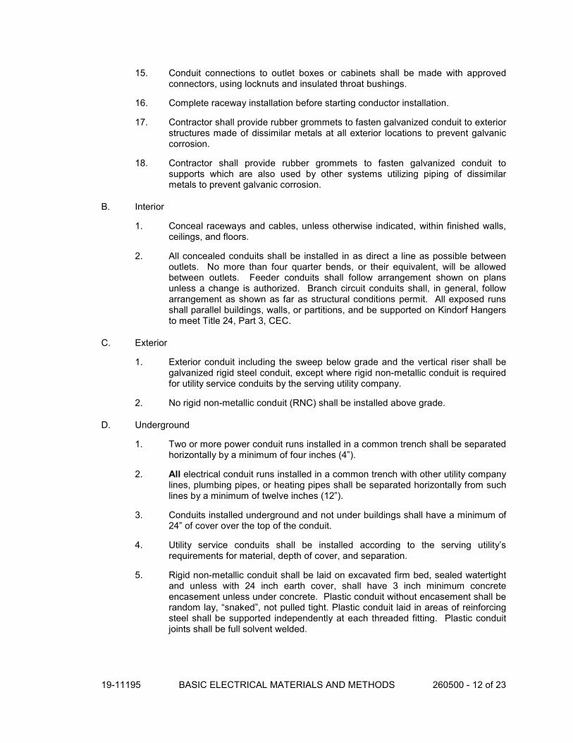
19-11195 BASIC ELECTRICAL MATERIALS AND METHODS 260500 - 12 of 23
15. Conduit connections to outlet boxes or cabinets shall be made with approved connectors, using locknuts and insulated throat bushings.
16. Complete raceway installation before starting conductor installation.
17. Contractor shall provide rubber grommets to fasten galvanized conduit to exterior structures made of dissimilar metals at all exterior locations to prevent galvanic corrosion.
18. Contractor shall provide rubber grommets to fasten galvanized conduit to supports which are also used by other systems utilizing piping of dissimilar metals to prevent galvanic corrosion.
B. Interior
1. Conceal raceways and cables, unless otherwise indicated, within finished walls, ceilings, and floors.
2. All concealed conduits shall be installed in as direct a line as possible between outlets. No more than four quarter bends, or their equivalent, will be allowed between outlets. Feeder conduits shall follow arrangement shown on plans unless a change is authorized. Branch circuit conduits shall, in general, follow arrangement as shown as far as structural conditions permit. All exposed runs shall parallel buildings, walls, or partitions, and be supported on Kindorf Hangers to meet Title 24, Part 3, CEC.
C. Exterior
1. Exterior conduit including the sweep below grade and the vertical riser shall be galvanized rigid steel conduit, except where rigid non-metallic conduit is required for utility service conduits by the serving utility company.
2. No rigid non-metallic conduit (RNC) shall be installed above grade.
D. Underground
1. Two or more power conduit runs installed in a common trench shall be separated horizontally by a minimum of four inches (4”).
2. All electrical conduit runs installed in a common trench with other utility company lines, plumbing pipes, or heating pipes shall be separated horizontally from such lines by a minimum of twelve inches (12”).
3. Conduits installed underground and not under buildings shall have a minimum of 24” of cover over the top of the conduit.
4. Utility service conduits shall be installed according to the serving utility’s requirements for material, depth of cover, and separation.
5. Rigid non-metallic conduit shall be laid on excavated firm bed, sealed watertight and unless with 24 inch earth cover, shall have 3 inch minimum concrete encasement unless under concrete. Plastic conduit without encasement shall be random lay, “snaked”, not pulled tight. Plastic conduit laid in areas of reinforcing steel shall be supported independently at each threaded fitting. Plastic conduit joints shall be full solvent welded.

19-11195 BASIC ELECTRICAL MATERIALS AND METHODS 260500 - 13 of 23
6. Rigid non-metallic conduit installed underground and not below a building slab shall have a galvanized rigid steel long radius elbow installed at the terminating end where the transition from horizontal to vertical occurs.
E. In Concrete Slabs
1. Conduit installed within concrete slabs shall be Schedule 80 PVC rigid non-metallic conduit or full weight galvanized rigid steel conduit.
2. Conduits in concrete slabs 3 inches thick or less shall not be of size larger than ¾ inch nominal trade size, and wired to top of reinforcing steel.
3. Conduit installed in concrete slabs shall be installed in the middle third of the slab thickness where practical, and have at least 1-inch concrete cover.
4. Secure raceways to reinforcing rods to prevent sagging or shifting during concrete placement.
5. Conduit installed in concrete slabs shall be installed side-by-side horizontally and shall have no less than 1” spacing between each conduit to allow for concrete consolidation to prevent voids in the concrete. Conduits that are installed in concrete slabs shall be arranged such that they do not cross over other conduits within the concrete slab. Where crossing of conduits is unavoidable the crossing sets of conduits shall be installed below the slab. No more than 3 conduits shall be installed side-by-side in a concrete slab without special permission from the structural engineer.
6. Install conduit larger than 1-inch trade size parallel to or at right angles to main reinforcement. Where conduit is at right angles to reinforcement, place conduit close to slab support.
7. Contractor shall be responsible for damages to membrane and shall repair it.
F. Below Grade Level Concrete Building Slab
1. All conduits below the building slab shall be Schedule 40 PVC rigid nonmetallic conduit or full weight galvanized rigid steel conduit, and shall have a 6” minimum cover below the floor slab measured from the bottom of the floor slab to the top of the conduit.
2. Rigid non-metallic conduits that are 1” trade size or smaller that are installed below the building slab shall transition from Schedule 40 PVC below the building slab to Schedule 80 PVC rigid nonmetallic conduit or galvanized rigid steel conduit, before passing into the concrete building slab and shall transition to galvanized rigid steel conduit or IMC within the concrete building slab before exiting and rising above the building slab.
3. Rigid non-metallic conduits that are 1 ¼” trade size or larger that are installed below the building slab shall have a galvanized rigid steel long radius elbow installed at the terminating end where the transition from horizontal to vertical occurs and the vertical riser shall be galvanized rigid steel conduit rising above the building slab.
4. Rigid non-metallic conduit installed underground and not below a building slab.

19-11195 BASIC ELECTRICAL MATERIALS AND METHODS 260500 - 14 of 23
5. Where conduits rise through the building slab they shall be installed at sufficient depth so that the curved portion of any bends, sweeps, or 90’s are not visible above the finished slab.
6. Contractor shall be responsible for damages to membrane and shall repair it.
G. In Beams and Footings
1. Conduit in concrete beam and footings shall be perpendicular to direction of beams unless otherwise indicated on structural drawings.
2. Conduit shown in concrete beam parallel to beams shall be installed at approximate mid-depth of beam.
H. Flexible Conduit
1. LFMC or FMC shall be used to connect motors and equipment subject to vibration, noise transmission, or movement to junction boxes, with a maximum length of 24-inches.
2. Install separate ground conductor across flexible connections.
3. Flexible conduits shall be independently suspended.
3.4 SURFACE MOUNTED RACEWAY INSTALLATION
A. Surface Mounted Raceways shall be used to provide raceway systems for branch circuits.
B. Surface Mounted Raceways shall be used only in dry interior locations, as allowed in Article 388 (Surface Nonmetallic Raceways) of the California Electrical Code.
C. Surface Mounted Raceways and wire distribution systems shall contain no more than six current carrying conductors in each section or compartment. Where additional conductors are required, additional raceway shall be installed to accommodate additional conductors.
D. Electrical and mechanical rooms are specifically excluded from the use of non-metallic Surface Mounted Raceways.
3.5 CONDUCTOR APPLICATION
A. Feeders and branch circuits shall be Type THHN/THWN insulated conductors in raceway.
B. Underground feeders and branch circuits shall be Type THWN or single-wire, Type UF insulated conductors in raceway.
C. Branch circuits for other than lighting circuits shall be Type THW or THHN/THWN insulated conductors in raceway. Lighting branch circuits shall be Type THW or THHN/THWN insulated conductors in raceway where exposed and may be metal-clad cable where concealed in ceilings and gypsum board partitions.

19-11195 BASIC ELECTRICAL MATERIALS AND METHODS 260500 - 15 of 23
D. ”Minimum conductor size shall be #12 for power and lighting, #14 for 120V control circuits and #18 for 24V control circuits.
E. Remote control, signaling and power-limited circuits shall be Type THHN/THWN insulated conductors in raceway for Classes 1, 2, and 3, unless otherwise indicated.
3.6 CONDUCTOR INSTALLATION
A. Conductors shall be continuous from outlet to outlet, no splices shall be made except within outlet or junction boxes.
B. Wiring at outlets shall be installed with at least 12 inches of slack conductor at each outlet.
C. Outlet and component connections shall be made to wiring systems and to ground. Electrical connectors and terminals shall be tightened according to manufacturer’s published torque-tightening values. Torque values specified in UL 486A shall be used where manufacturer’s torque values are not indicated.
D. Wire in panels, cabinets, pull boxes, and wiring gutters shall be squared, labeled, and neatly grouped with cable ties and fanned out to the terminals.
E. All branch circuits, fixture wiring joints, splices, and taps for conductors #10 and smaller shall be made with 3M “Scotchlock” connectors, or approved equal.
F. All branch circuits, fixture wiring joints, splices, and taps for conductors #8 and larger shall be made with two-bolt type solderless connectors or T & B “color keyed” compression lugs.
G. Bolt-type solderless connectors shall be torqued with a torque wrench according to the manufacturer’s recommendations, and then retightened after 24-48 hours before taping. Owners’ inspector shall be informed of this procedure during the waiting period and shall witness the act of retightening.
H. Connectors and lugs for terminating stranded conductors #8 and larger shall be machine crimp compression type.
I. All splices shall be taped with Scotch #88 plastic electrical tape with “Scotch Fill” where necessary for a smooth joint. Scotch #27 or #2520 shall be used for other than normal temperatures or conditions. All connections and splices shall be electrically perfect and in strict accordance with all code requirements.
J. No splices shall be made below grade in a manhole or pullholes without Engineer’s written approval, and then shall be encapsulated with 3M potting kits per 3M Specifications. For larger gauge wire where 3M potting kits are prohibited Contractor shall use submersible UL listed Polaris connectors by NSi.
3.7 WIREWAY AND AUXILIARY GUTTER APPLICATION

19-11195 BASIC ELECTRICAL MATERIALS AND METHODS 260500 - 16 of 23
A. Wireways and auxiliary gutters shall be used above and below panelboards, lighting relay cabinets, and terminal cabinets to accommodate large concentrations of wires.
3.8 PULL BOXES AND WIREWAYS:
A. Boxes shall be installed square and plumb. An engraved nameplate shall be installed on each box indicating its function. Nameplate shall be installed on the exterior of each box in unfinished areas and on the interior of each box in finished areas.
B. Wireways shall be installed with strip-type connectors with self-retained mounting screws. Hangers with two piece, hook together features shall be used to permit preassembly of wireway and hanger bottom plate before hanging on a preinstalled upper bracket.
C. Pull and junction boxes shall be installed as shown to ease the pulling of wire and to comply with CEC requirements.
3.9 WIRING DEVICES AND MATERIALS
A. Outlets shall be mounted at 18” minimum above finished floor unless otherwise noted.
B. The locations of outlets shown on drawings shall be located with respect to work of others and to be symmetrical with room layout.
C. Outlets in architectural patterned surfaces such as tile and finish panels shall be centered on intersections of four panels or in exact center of panels, unless otherwise shown on architectural plans or directed by Architect.
D. Outlet boxes for concealed work shall be one-piece steel knock out type with zinc coating. Boxes shall not be smaller than 4” square nominal size, unless otherwise indicated. Extension rings, plaster rings, and covers shall be provided as necessary for flush finish.
E. The Contractor shall inform himself of wall thickness throughout the building and shall provide outlet boxes of suitable depth that can be flush mounted and yet will be deep enough to contain the particular apparatus involved. Location of exposed pull or junction boxes will be subject to the Architect’s approval.
F. Outlet boxes on opposite sides of walls shall not be placed back-to-back, nor shall “through” boxes be employed (except where specifically permitted on the drawings by note).
G. Bar hangers shall be used to support outlet boxes in stud or furred partitions and ceilings. Attachment screws, devices, etc., shall be of the proper type to secure boxes to metal studs complemented by expansion shields to concrete and masonry.
H. All outlet boxes and particularly those supporting fixtures shall be securely anchored in place in an approved manner. Support outlet boxes and fixtures in acoustic ceiling areas from building structures, not from acoustic ceilings. All lighting fixture outlets shall be coordinated with mechanical, architectural, or other equipment to eliminate conflicts and provide a workable, neat installation.

19-11195 BASIC ELECTRICAL MATERIALS AND METHODS 260500 - 17 of 23
I. Approved knock out holes shall be provided. Outlet boxes from which light fixtures will be suspended shall be equipped with 3/8” fixture studs fastened through from back of box.
J. Surface boxes of the cast metal threaded hub type with suitable gasketed covers shall be used for exposed conduit runs less than 5’ above a finished floor or where waterproof boxes are required.
K. Masonry boxes shall have conduit entrances to rear of box with depth as required to clear masonry.
L. Boxes shall be sized for number of conductors entering box.
M. Wiring devices shall be securely fastened to the outlet box. Where the outlet box covers are back from the finished walls, the device shall be built out with washers so that it is rigidly held in place to the box. Metal extenders shall be provided in flammable construction per CEC.
N. All device screw slots shall be left in a vertical orientation.
O. Connect wiring device grounding terminal to branch-circuit equipment grounding conductor and to outlet box with bonding jumper.
P. Connect ground terminal of isolated-ground receptacles to isolated-ground conductor routed to designated isolated equipment ground terminal of electrical system.
3.10 PANELBOARDS
A. All panels shall have, in addition to conduit shown on the drawings, two ¾” and three 1” conduits stubbed to nearest accessible attic space.
B. All panels shall be installed with the top of the trim at 6’-0” above the finished floor, unless otherwise indicated on the drawings.
C. Where space permits, panels shall be surface mounted where they are not visible to the public.
D. A typewritten directory shall be mounted behind plastic in a metal holder welded to the inside of each panel door showing circuit numbers and complete description of all outlets on each circuit and an Arc-Flash Hazard Warning label shall be applied to each panelboard in accordance with CEC 110.16.
E. Labeling of all circuits at panel boards shall match the exact room names of each of the spaces. Verify exact room names with Owner prior to labeling.
3.11 DISCONNECT DEVICES
A. Thoroughly examine site conditions for acceptance of disconnects switch installation to verify conformance with manufacturer and specification tolerances. Do not commence with installation until all conditions are made satisfactory.

19-11195 BASIC ELECTRICAL MATERIALS AND METHODS 260500 - 18 of 23
B. Coordinate locations of switches and equipment in the field to provide code required clearances in front of switches and to insure that switches are in sight of the controllers as described in NEC Article 430.
C. Install disconnect switches where indicated on the Drawings.
D. Install fuses in fusible disconnect switches.
E. Include construction channel and mounting hardware as required to support disconnect switch.
F. Provide engraved, machine screw retained nameplate on each disconnect switch. Name plate shall identify equipment and panelboard + branch circuit breaker.
3.12 SUPPORTING DEVICE APPLICATION
A. Hot-dip galvanized materials or nonmetallic channel and angle system components shall be used in damp locations and outdoors.
B. Steel materials shall be used in dry locations.
C. Support clamps for PVC raceways shall be click-type clamp system.
D. Strength of supports shall be adequate to carry present and future loads, times a safety factor of at least four with a minimum of 200-lb design load.
3.13 SUPPORT INSTALLATION
A. Install support devices to securely and permanently fasten and support electrical components.
B. Install individual and multiple raceway hangers and riser clamps to support raceways. Provide U-bolts, clamps, attachments, and other hardware necessary for hanger assemblies and for securing hanger rods and conduits.
C. Support parallel runs of horizontal raceways together on trapeze- or bracket-type hangers.
D. Size supports for multiple raceway installations so capacity can be increased by a 25 percent minimum in the future.
E. Support individual horizontal raceways with separate, malleable-iron pipe hangers or clamps.
F. Install 1/4-inch diameter or larger threaded steel hanger rods, unless otherwise indicated.
G. Spring-steel fasteners specifically designed for supporting single conduits or tubing may be used instead of malleable-iron hangers for 1-1/2-inch and smaller raceways serving lighting and receptacle branch circuits above suspended ceilings and for fastening raceways to slotted channel and angle supports.

19-11195 BASIC ELECTRICAL MATERIALS AND METHODS 260500 - 19 of 23
H. Arrange supports in vertical runs so the weight of raceways and enclosed conductors is carried entirely by raceway supports, with no weight load on raceway terminals.
I. Simultaneously install vertical conductor supports with conductors.
J. Separately support cast boxes that are threaded to raceways and used for fixture support. Support sheet-metal boxes directly from the building structure or by bar hangers. If bar hangers are used, attach bar to raceways on opposite sides of the box and support the raceway with an approved fastener not more than 24 inches from the box.
K. Install metal channel racks for mounting cabinets, panelboards, disconnect switches, control enclosures, pull and junction boxes, transformers, and other devices unless components are mounted directly to structural elements of adequate strength.
L. Install sleeves for cable and raceway penetrations of concrete slabs and walls unless core-drilled holes are used. Install sleeves for cable and raceway penetrations of masonry and fire-rated gypsum walls and of all other fire-rated floor and wall assemblies. Install sleeves during erection of concrete and masonry walls.
M. Securely fasten electrical items and their supports to the building structure, according to the following criteria, unless otherwise noted:
1. Wood – wood screws or screw-type nails.
2. Masonry – toggle bolts on hollow masonry units, expansion bolts on solid masonry units.
3. New Concrete – concrete inserts with machine screws and bolts.
4. Existing Concrete – expansion bolts.
5. Steel – welded threaded studs or spring-tension clamps on steel. Field welding shall comply with AWS D1.1. Welding to steel structure may be used only for threaded studs, not for conduits, pipe straps, or other items.
6. Light Steel – sheet-metal screws.
7. Fasteners shall be selected so the load applied to each fastener does not exceed 25 percent of its proof-test load.
3.14 ELECTRICAL IDENTIFICATION
A. Each conductor of every system shall be permanently tagged in each panelboard, pull box, J-box, etc., in compliance with the Occupational Safety and Health Administration (OSHA).
B. Brady labels shall be used to identify terminals and destination of feeders, branch circuits, signal and control circuits, etc., at all terminations, junction boxes and pull boxes, and shall be coordinated with the nameplates in all boxes and equipment.
C. All terminals in the switchboards, panels, relays, switches, devices, starter terminals, etc., shall have Brady labels for identification to identify both ends of all wiring.

19-11195 BASIC ELECTRICAL MATERIALS AND METHODS 260500 - 20 of 23
D. The Contractor shall furnish and install 1” x 3” x 3/32” thick laminated black Bakelite nameplates with a white core (unless specifically shown as red) engraved to produce white letters on black background for all items of electrical equipment, including 2-pole and 3-pole circuit breakers, panelboards, starters, relays, time switches and disconnect switches.
E. All devices shall have their branch circuit identified on the back side of device plate with a permanent type black marker, i.e. CT A-21. Identify panelboard and circuit number from which receptacles are served. Use machine-printed, pressure-sensitive, abrasion-resistant label tape on face of plate and durable wire markers or tags within outlet boxes.
F. Coordinate names, abbreviations, colors, and other designations used for electrical identification with corresponding designations indicated in the Contract Documents or required by codes and standards. Use consistent designations throughout Project.
G. Panels having single-pole circuit breakers shall be provided with typed schedules mounted in welded metal holders behind plastic.
H. Clean surfaces that are to receive self-adhesive identification products before applying.
I. Where three or more switches are ganged, and elsewhere as indicated, identify each switch with approved legend engraved on wall plate.
J. Identify raceways and cables with color banding as follows:
1. Bands: Pretensioned, snap-around, colored plastic sleeves or colored adhesive marking tape. Make each color band 2 inches wide, completely encircling conduit, and place adjacent bands of two-color markings in contact, side by side.
2. Band Locations: At changes in direction, at penetrations of walls and floors, at 50-foot maximum intervals in straight runs, and at 25-foot maximum intervals in congested areas.
3. Colors: As follows:
a. Fire Alarm System: Red.
b. Security System: Blue and yellow.
c. Telecommunication System: Green and yellow.
K. Tag and label circuits designated to be extended in the future. Identify source and circuit numbers in each cabinet, pull and junction box, and outlet box. Color-coding may be used for voltage and phase identification.
L. Install continuous underground plastic markers during trench backfilling, for exterior underground power, control, signal, and communication lines located directly above power and communication lines. Locate 6 to 8 inches below finished grade. If width of multiple lines installed in a common trench or concrete envelope does not exceed 16 inches, overall, use a single line marker.
M. All power conductors shall be identified in accordance with the following schedule:
1. 120/208V, 3 Phase, 4 Wire System.
a. Phase A: Black.

19-11195 BASIC ELECTRICAL MATERIALS AND METHODS 260500 - 21 of 23
b. Phase B: Red.
c. Phase C: Blue.
d. Neutral: White.
e. Ground: Green
2. 120/240V, 3 Phase, 4 Wire System.
a. Phase A: Black.
b. Phase B (Stinger): Orange.
c. Phase C: Blue.
d. Neutral: White
e. Ground: Green
3. 277/480V, 3 Phase, 4 Wire System.
a. Phase A: Brown.
b. Phase B: Orange.
c. Phase C: Yellow.
d. Neutral: White with a colored stripe or gray.
e. Ground: Green.
4. Isolated ground conductor shall be green with a yellow stripe.
N. Install warning, caution, and instruction signs where required to comply with 29 CFR, Chapter XVII, Part 1910.145, and where needed to ensure safe operation and maintenance of electrical systems and of items to which they connect. Install engraved plastic-laminated instruction signs with approved legend where instructions are needed for system or equipment operation. Install metal-backed butyrate signs for outdoor items.
O. Install engraved-laminated emergency-operating signs with white letters on red background with minimum 3/8-inch high lettering for emergency instructions on power transfer, load shedding, and other emergency operations.
3.15 UTILITY COMPANY ELECTRICITY-METERING EQUIPMENT
A. Equipment shall be installed according to governing electric utility company’s written requirements. Grounding and empty conduits shall be provided as required by utility company.
3.16 FIRESTOPPING
A. Seal all penetrations for work of this section through fire rated floors, walls and ceilings to prevent the spread of smoke, fire, toxic gas or water through the penetration, either before, during, or after the fire. The fire and temperature ratings of the penetration assembly shall be at least that of the floor, wall, or ceiling into which it is installed so that the original fire rating of the floor or wall is maintained as required by Article 300.21 of the California Electrical Code (CEC).

19-11195 BASIC ELECTRICAL MATERIALS AND METHODS 260500 - 22 of 23
B. Where applicable, provide OZ Type CFSF/I and CAFSF/I fire seal fittings for conduit and cable penetrations through concrete and masonry walls, floors, slabs and similar structures. Where applicable, provide 3M fire barrier sealing penetration system, and/or Thomas and Bett Flame Safe Fire Stop System, and/or Chase Foam fire stop system, including wall wrap, partitions, caps and other accessories as required. All manufacturers’ instructions and recommendations for installation of sealing fittings and barrier sealing systems.
C. The Contractor shall repair and refinish disturbed finish materials and other surfaces to match adjacent undisturbed new structures, surfaces and shall install new fireproofing where existing firestopping has been disturbed. The repair and refinishing of materials and other surfaces shall be by skilled mechanics of the trades involved.
3.17 REFINISHING AND TOUCHUP PAINTING
A. The Contractor shall clean damaged and disturbed areas and apply primer, intermediate, and finish coats to suit the degree of damage at each location. He shall follow paint manufacturer’s written instructions for surface preparation and for timing and application of successive coats.
B. Damage to galvanized finishes shall be repaired with zinc-rich paint recommended by manufacturer.
C. Damage to PVC or paint finishes shall be repaired with matching touchup coating recommended by manufacturer.
D. See Section 09900, “Painting”.
3.18 FIELD QUALITY CONTROL
A. Test Owner’s electricity-metering installation for proper operation, accuracy, and usability of output data.
1. Connect a load of known kW rating, 1.5 kW minimum, to a circuit supplied by the metered feeder.
2. Turn off circuits supplied by the metered feeder and secure them in the “off” condition.
3. Run the test load continuously for eight hours, minimum, or longer to obtain a measurable meter indication. Use a test load placement and setting that ensure continuous, safe operation.
4. Check and record meter reading at end of test period and compare with actual electricity used based on test load rating, duration of test, and sample measurements of supply voltage at the test load connection. Record test results.
5. Repair or replace malfunctioning metering equipment or correct test setup; then retest. Repeat for each meter in installation until proper operation of entire system is verified.

19-11195 BASIC ELECTRICAL MATERIALS AND METHODS 260500 - 23 of 23
3.19 SYSTEM TESTING AND STARTUP
A. Refer to Specification Section 269500 “Electrical Acceptance Tests” for minimum required systems testing and startup.
END OF SECTION 260500


19-11195 GROUNDING 260526 - 1 of 6
SECTION 260526 GROUNDING
PART 1 - GENERAL
1.1 RELATED DOCUMENTS
A. Drawings and general provisions of the Contract, including General and Supplementary Conditions and Division 01 Specification Sections shall form a part of this Section, with the same force and effect as though repeated here.
1.2 SUMMARY
A. This Section includes grounding of electrical systems and equipment and basic requirements for grounding for protection of life, equipment, circuits, and systems. Grounding requirements specified in this Section may be supplemented in other Sections of these Specifications.
1.3 SUBMITTALS
A. Submittals for this Section shall be made according to the Conditions of the Contract, Division 01 Specification Sections and Specification Section 260100.
B. Product Data for grounding rods, connectors and connection materials, and grounding fittings.
C. Qualification data for firms specified in "Quality Assurance" Article to demonstrate their capabilities and experience.
D. Field tests and observation reports certified by the testing organization and indicating and interpreting the test reports for compliance with performance requirements.
1.4 QUALITY ASSURANCE
A. Testing Agency Qualifications: A "Nationally Recognized Testing Laboratory" (NRTL) as defined in OSHA Regulation 1910.7, or a full member company of the InterNational Electrical Testing Association (NETA).
1. Testing Agency Field Supervision: Use persons currently certified by NETA or the National Institute for Certification in Engineering Technologies to supervise on-site testing specified in Part 3.
B. Comply with UL 467.
PART 2 - PRODUCTS
2.1 MANUFACTURERS

19-11195 GROUNDING 260526 - 2 of 6
A. Manufacturers: Subject to compliance with requirements, provide products by one of the following:
1. Chance: A. B. Chance Co.
2. Erico Inc.; Electrical Products Group.
3. Galvan Industries, Inc.
4. Lyncole XIT Grounding.
5. Raco, Inc.
6. Thomas & Betts, Electrical.
2.2 GROUNDING AND BONDING PRODUCTS
A. Where types, sizes, ratings, and quantities indicated are in excess of California Electrical Code (CEC) requirements, the more stringent requirements and the greater size, rating, and quantity indications govern.
2.3 WIRE AND CABLE GROUNDING CONDUCTORS
A. Conform to CEC Table 8, except as otherwise indicated, for conductor properties, including stranding.
1. Material: Copper.
B. Equipment Grounding Conductors: Insulated with green color insulation.
C. Grounding-Electrode Conductors: Stranded cable.
D. Isolated Grounding Conductors: Insulated with green color, yellow striping insulation.
E. Bare Copper Conductors: Conform to the following:
1. Solid Conductors: ASTM B 3.
2. Assembly of Stranded Conductors: ASTM B 8.
3. Tinned Conductors: ASTM B 33.
2.4 MISCELLANEOUS CONDUCTORS
A. Grounding Bus: Bare, annealed-copper bars of rectangular cross section.
B. Braided Bonding Jumpers: Copper tape, braided No. 30 AWG bare copper wire, terminated with copper ferrules.
C. Bonding Straps: Soft copper, 0.05 inch thick and 2 inches wide, except as indicated.
2.5 CONNECTOR PRODUCTS

19-11195 GROUNDING 260526 - 3 of 6
A. Grounding connections shall be exothermic welded, bolted clamp terminal, or pressure connector type.
B. Exothermic-Welded Connections shall be provided in kit form and selected per manufacturer's written instructions for specific types, sizes, and combinations of conductors and connected items.
C. Bolted Clamp connectors shall be heavy-duty type.
D. Pressure connectors shall be high-conductivity-plated units.
2.6 GROUNDING ELECTRODES AND TEST WELLS
A. Grounding Rods shall be sectional type; copper-clad steel.
1. Size: 3/4 inch by 120 inches.
B. Plate Electrodes shall be copper, square or rectangular shape. Minimum 0.10 inch thick, size as indicated.
C. Test Wells shall consist of a Christy Concrete Products F8 Box, or equal.
PART 3 - EXECUTION
3.1 GENERAL
A. The conduit system, supports, cabinets, switchboards, etc., and neutral conductors must be permanently and effectively grounded by means of approved ground clamps, in accordance with Title 24 of the California Code of Regulations. The neutral shall only be grounded at the main service location unless specifically noted otherwise on the drawings or required by the California Electrical Code.
B. This Contractor shall exercise every precaution to obtain good contacts at all panel boxes, pull boxes, etc. Where it is not possible to obtain good contacts, the conduits shall be bonded around the boxes with a #6 AWG gauge, THWN wire with ground clamps.
C. Where there is more than one building supplied from a common service, provide a grounding electrode system at each building per CEC 250.50 and connect per CEC 250.32(B)(1).
3.2 APPLICATION
A. General
1. All equipment cases, motor frames, etc. shall be completely grounded to satisfy applicable code requirements.
2. The interior hot and cold water piping and the interior above ground gas piping shall be bonded to the building service equipment per CEC 250.104.
3. Do not use underground gas piping as a grounding electrode.

19-11195 GROUNDING 260526 - 4 of 6
B. Equipment Grounding Conductor
1. Pull an Equipment Grounding Conductor, insulated green, in ALL conduits, both metallic and non-metallic, unless they are designated for telephone or data cables.
2. Each disconnect switch shall have an Equipment Grounding Conductor (lay in wire type) which shall be used for grounding the disconnect enclosure. The ground wire shall continue and be connected to the enclosure of the equipment served.
3. Comply with CEC Article 250 for types, sizes, and quantities of Equipment Grounding Conductors, except where specific types, larger sizes, or more conductors than required by CEC are indicated.
4. Install separate Equipment Grounding Conductor in branch circuit runs from computer area power panels or power-distribution units.
C. Air-Duct Equipment Circuits
1. Install an Equipment Grounding Conductor to duct-mounted electrical devices operating at 120 V and above, including air cleaners and heaters. Bond conductor to each unit and to air duct.
3.3 INSTALLATION
A. General: Ground electrical systems and equipment according to CEC requirements, except where Drawings or Specifications exceed CEC requirements.
B. Grounding Rods: Locate a minimum of 1-rod length from each other and at least the same distance from any other grounding electrode.
1. Drive until tops are 2 inches below finished floor or final grade, except as otherwise indicated.
2. Interconnect with grounding-electrode conductors. Use exothermic welds, except at test wells and as otherwise indicated. Make these connections without damaging copper coating or exposing steel.
C. Grounding Conductors: Route along the shortest and straightest paths possible, except as otherwise indicated. Avoid obstructing access or placing conductors where they may be subjected to strain, impact, or damage.
D. Underground Grounding Conductors: Use bare copper wire. Bury at least 24 inches below grade.
E. Metal Water Service Pipe: Provide insulated copper grounding conductors, sized as indicated, in conduit, from building's main service equipment, or grounding bus, to main metal water service entrances to building. Connect grounding conductors to main metal water service pipes by grounding-clamp connectors. Where a dielectric main water fitting is installed, connect grounding conductor to street side of fitting. Do not install a grounding jumper across dielectric fittings. Bond grounding-conductor conduit to conductor at each end.
F. Water Meter Piping: Use braided-type bonding jumpers to electrically bypass water meters. Connect to pipe with grounding-clamp connectors.

19-11195 GROUNDING 260526 - 5 of 6
G. Bond interior metal piping systems and metal air ducts to equipment grounding conductors of associated pumps, fans, blowers, electric heaters, and air cleaners. Use braided-type bonding straps.
H. Test Wells: One for each driven grounding electrode, except as otherwise indicated. Set top of well flush with finished grade or floor. Fill with 1-inch- maximum-size crushed stone or gravel.
I. Ufer Ground (Concrete-Encased Grounding Electrode): Fabricate according to CEC Paragraph 250.52(A)(3), using a minimum of 20 feet of bare copper conductor not smaller than No. 4 AWG. Where base of concrete foundation is less than 20 feet in length, coil excess conductor within base of concrete foundation. Bond grounding conductor to reinforcing steel to at least 4 locations, and to anchor bolts. Extend grounding conductor below grade and connect to building grounding grid or to a grounding electrode external to concrete.
3.4 CONNECTIONS
A. General: Make connections so possibility of galvanic action or electrolysis is minimized. Select connectors, connection hardware, conductors, and connection methods so metals in direct contact will be galvanically compatible.
1. Use electroplated or hot-tin-coated materials to assure high conductivity and to make contact points closer in order of galvanic series.
2. Make connections with clean, bare metal at points of contact.
3. Make aluminum-to-steel connections with stainless-steel separators and mechanical clamps.
4. Make aluminum-to-galvanized steel connections with tin-plated copper jumpers and mechanical clamps.
5. Coat and seal connections having dissimilar metals with inert material to prevent future penetration of moisture to contact surfaces.
B. Exothermic-Welded Connections: Use for connections to structural steel and for underground connections, except those at test wells. Comply with manufacturer's written instructions. Welds that are puffed up or that show convex surfaces indicating improper cleaning are not acceptable.
C. Equipment Grounding-Wire Terminations: For No. 8 AWG and larger, use pressure-type grounding lugs. No. 10 AWG and smaller grounding conductors may be terminated with winged pressure-type connectors.
D. Non-contact Metal Raceway Terminations: Where metallic raceways or metallic sheathed cables terminate at metal housings without mechanical and electrical connection to the housing, terminate each metallic raceway or metallic sheathed cable with a grounding bushing. Connect grounding bushings with a bare grounding conductor to grounding bus or terminal in housing. Bond electrically non-continuous conduits or sheathed cables at both entrances and exits with grounding bushings and bare grounding conductors, except as otherwise indicated.
E. Connections at Test Wells: Use compression-type connectors on conductors and make bolted- and clamped-type connections between conductors and grounding rods.

19-11195 GROUNDING 260526 - 6 of 6
F. Tighten screws and bolts for grounding and bonding connectors and terminals according to manufacturer's published torque-tightening values. Where these requirements are not available, use those specified in UL 486A and UL 486B.
G. Compression-Type Connections: Use hydraulic compression tools to provide correct circumferential pressure for compression connectors. Use tools and dies recommended by manufacturer of connectors. Provide embossing die code or other standard method to make a visible indication that a connector has been adequately compressed on grounding conductor.
H. Moisture Protection: Where insulated grounding conductors are connected to grounding rods or grounding buses, insulate entire area of connection and seal against moisture penetration of insulation and cable.
3.5 FIELD QUALITY CONTROL
A. Refer to Specification Section 269500 “Electrical Acceptance Tests” for minimum required testing of Grounding System.
3.6 ADJUSTING AND CLEANING
A. Restore surface features, including vegetation, at areas disturbed by work of this Section. Reestablish original grades, except as otherwise indicated. Where sod has been removed, replace it as soon as possible after backfilling is completed. Restore areas disturbed by trenching, storing of dirt, cable laying, and other activities to their original condition. Include topsoiling, fertilizing, liming, seeding, sodding, sprigging, and mulching. Comply with Division 02 Section "Landscaping." Maintain restored surfaces. Restore disturbed paving as indicated.
END OF SECTION 260526

19-11195 SWITCHBOARDS 262413 - 1 of 6
SECTION 262413 SWITCHBOARDS
PART 1 - GENERAL
1.1 WORK INCLUDED
A. Furnish and install the main switchboard as herein specified.
1.2 REFERENCES
A. The switchboard and overcurrent protection devices referenced herein shall be designed and manufactured according to the following appropriate specifications.
1. 2016 California Electrical Code (CEC).
2. NEMA PB 2 - Deadfront Distribution Switchboards, File E8681
3. NEMA PB 2.1 - Proper Handling, Installation, Operation and Maintenance of Deadfront Switchboards Rated 600 Volts or Less.
4. UL 489 - Molded Case Circuit Breakers.
5. UL 891 - Dead-Front Switchboards.
1.3 SUBMITTALS
A. Submittals for this Section shall be made according to the Conditions of the Contract, Division 01 Specification Sections and Specification Section 260100.
B. Shop Drawings
1. Submit Shop Drawings for each switchboard indicating front and side enclosure elevations with overall dimensions, conduit entrance locations and requirements, nameplate legends, one-line diagrams, equipment schedule and switchboard instrument details.
C. Test Reports
1. Submit certified reports of Independent Tests and Observations indicating and interpreting test results specified in Part 3 of this Section.
2. Submit calibration record for all testing devices used.
3. Submit certificates, signed by Contractor, certifying that Independent Testing Agency complies with requirements specified in Section 260100 / 269500, Article 1.2.
D. Operation and Maintenance Data
1. Submit operation and maintenance data for switchboards to include in “Operations and Maintenance Instructions” manuals specified in Division 01 and

19-11195 SWITCHBOARDS 262413 - 2 of 6
Specification Section 260100, Article 1.6, including detailed manufacturer’s written instructions on adjusting overcurrent protective devices.
1.4 DELIVERY, STORAGE, AND HANDLING
A. Deliver, store, protect, and handle products in conformance with manufacturer's recommended practices as outlined in applicable Installation and Maintenance Manuals.
B. Each switchboard section shall be delivered in individual shipping splits for ease of handling. They shall be individually wrapped for protection and mounted on shipping skids.
C. Inspect and report concealed damage to carrier within their required time period.
D. Store in a clean, dry space. Maintain factory protection and/or provide an additional heavy canvas or heavy plastic cover to protect structure from dirt, water, construction debris, and traffic. Where applicable, provide adequate heating within enclosures to prevent condensation.
E. Handle in accordance with NEMA PB 2.1 and manufacturer's written instructions. Lift only by lifting means provided for this express purpose. Handle carefully to avoid damage to switchboard internal components, enclosure, and finish.
1.5 PROJECT CONDITIONS
A. Verify dimensions by field measurements.
B. Determine suitable path for moving switchboard into place considering project conditions.
C. Verify clearance requirements. Locate switchboard to meet installation tolerances.
D. Revise locations and elevations from those indicated as required to suit project conditions.
1.6 WARRANTY
A. Manufacturer shall warrant equipment to be free from defects in materials and workmanship for the lesser of one (1) year from date of installation or eighteen (18) months from date of purchase.
PART 2 - PRODUCTS
2.1 MANUFACTURERS
A. This design is based on the use of equipment manufactured by Square D Company. Subject to compliance with project requirements, equivalent products by one of the following manufacturers may be considered:
1. Square D Company;

19-11195 SWITCHBOARDS 262413 - 3 of 6
2. General Electric Company;
3. Eaton;
4. Siemens;
2.2 SWITCHBOARD - GENERAL
A. Switchboards shall be rated with a minimum short circuit current rating 65,000 rmssymmetrical amperes at 240 VAC maximum. Continuous bus ratings shall be as shownon drawings. Switchboards shall be legibly marked with the maximum available faultcurrent obtained from the utility company; the marking shall include the date that the faultcurrent calculation was performed.
B. Switchboards shall bear an Arc-Flash Hazard warning label in accordance with CECArticle 110.16.
C. The main switchboard and each switchboard containing a main circuit breaker utilized asa building main disconnect shall have a permanently installed user-accessible meterSquare D Power Logic Model PM870MG with PM8ECC module with 10/100BaseTx UTPport, RS-485 Modbus serial master port, Ethernet to serial line gateway, embedded webserver, that is separate and in addition to the utility company meter. The user-accessiblemeter shall provide all of the following functions:
1. Instantaneous (at the time) kW demand
2. Historical peak kW demand
3. Tracking kWh for user-definable period
4. Ethernet network connection
D. All unused spaces provided, unless otherwise specified, shall be fully equipped for futuredevices, including all appropriate connectors and mounting hardware.
E. Enclosure shall be NEMA 250, Type 3R Rainproof.
1. Sections shall be aligned front and rear.
2. Switchboard height shall be 90.0 inches including 1.5-inch floor sills andexcluding lifting members and pull boxes.
3. The switchboard shall be of deadfront construction.
4. The switchboard frame shall be of formed steel rigidly bolted together to supportall cover plates, bussing and component devices during shipment andinstallation.
5. Steel base channels shall be bolted to the frame to rigidly support the entireshipping section for moving on rollers and floor mounting.
6. Each switchboard section shall have an open bottom and an individuallyremovable top plate for installation and termination of conduit.
7. Barriers shall be provided between adjacent switchboard sections.
8. The switchboard enclosure shall be painted on all exterior surfaces inmanufacturer’s standard color, applied over a corrosion-resistant undercoating.

19-11195 SWITCHBOARDS 262413 - 4 of 6
9. All front covers shall be screw removable with a single tool and all doors shall be hinged with removable hinge pins.
10. Top and bottom conduit areas shall be clearly indicated on shop drawings.
F. Utility Pull and/or Metering compartments shall be fabricated to meet utility company’s requirements. If separate vertical section is required for utility metering, match and align with basic switchboard.
G. Bus Transition and Incoming Line Pull Sections shall be matched and aligned with basic switchboard.
H. Provide 1in H X 3in W engraved laminated nameplates for each device. Furnish black letters on a white background for all voltages.
I. Bus Composition shall be plated copper. Plating shall be applied continuously to all bus work. The switchboard bussing shall be of sufficient cross-sectional area to meet UL Standard 891 temperature rise requirements. The phase and neutral through-bus shall have an ampacity as shown in the plans. For 4-wire systems, the neutral shall be of equivalent ampacity as the phase bus bar. Tapered bus is not acceptable. Full provisions for the addition of future sections shall be provided. Bussing shall include all necessary hardware to accommodate splicing for future additions.
J. Bus Connections shall be bolted with Grade 5 bolts and conical spring washers.
K. Ground Bus shall be sized per NFPA 70 and UL 891 Tables 25.1 and 25.2 and shall extend the entire length of the switchboard. Provisions for the addition of future sections shall be provided.
L. The switchboard shall be accessible from the front, left side and right side.
2.3 MAIN OVERCURRENT PROTECTIVE DEVICE
A. Main Circuit Breaker shall be a fixed mounted, full function, thermal magnetic trip molded case circuit breaker.
2.4 DISTRIBUTION OVERCURRENT PROTECTIVE DEVICES
A. Distribution Circuit Breakers shall be NEMA AB 1, enclosed, Molded-Case Circuit Breakers, with lockable handles.
1. Frame size, trip rating, number of poles, and auxiliary devices shall be as indicated and interrupting capacity rating shall meet available fault current.
2. Overcurrent devices shall be listed for application, including switching fluorescent lighting loads or heating, air-conditioning and refrigerating equipment.
3. Circuit breakers, 400A and larger shall be equipped with trip units interchangeable within frame size.
4. pickup clearing time to be 2 times faster than the normal instantaneous pickup sensor amperage.
5. Mechanical lugs and power-distribution connectors shall be provided for number, size, and material of conductors indicated.

19-11195 SWITCHBOARDS 262413 - 5 of 6
B. Where indicated, equip compartments with mounting brackets, supports, bus connections, and appurtenances designed for future overcurrent protective device of types and ampere ratings indicated.
2.6 CUSTOMER METERING
A. Electronic digital true RMS sensing metering display for each main switchboard main and each feeder serving a busway.
2.7 METERING TRANSFORMERS
A. All instrument transformers shall be UL recognized per Classification XODW2.
PART 3 - EXECUTION
3.1 EXAMINATION
A. Examine area to receive switchboard to provide adequate clearance for switchboard installation.
B. Check that concrete pads are level and free of irregularities.
C. Start work only after unsatisfactory conditions are corrected.
3.2 INSTALLATION
A. Install switchboard in accordance with manufacturer's written guidelines, the NEC, and local codes.
B. Support switchboards on concrete housekeeping bases, 6-inch nominal thickness.
C. Remove temporary lifting eyes, channels, and brackets and temporary blocking of moving parts from switchboard units and components.
3.3 CONNECTIONS
A. Connect switchboards and components to wiring systems and to ground as indicated and instructed by manufacturer.
B. Tighten electrical connectors and terminals, including screws and bolts, according to manufacturer’s published torque-tightening values. Where manufacturer’s torque values are not indicates, use those specified in UL 786A and UL 486B.
3.4 FIELD QUALITY CONTROL
A. Refer to Specification Section 269500, Electrical Acceptance Testing, for minimum required switchboard testing by Contractor and Independent Testing Agency.

19-11195 SWITCHBOARDS 262413 - 6 of 6
3.5 ADJUSTING
A. Adjust all operating mechanisms for free mechanical movement per manufacturer's specifications.
B. Tighten bolted bus connections in accordance with manufacturer's instructions.
C. Adjust circuit breaker trip and time delay settings to values as instructed by the Engineer.
3.6 CLEANING
A. Upon completion of installation, inspect interior and exterior of switchboards. Remove paint spatters and other spots, dirt, and debris. Touch up scratches and mars of finish to match original finish.
END OF SECTION 262413

19-11195 PANELBOARDS 262416 - 1 of 5
SECTION 262416 PANELBOARDS
PART 1 - GENERAL
1.1 WORK INCLUDED
A. Furnish and install panelboards as herein specified.
1.2 REFERENCES
A. The panelboards and overcurrent protection devices referenced herein shall be designed and manufactured according to the following appropriate specifications.
1. NFPA 70 - California Electrical Code (CEC).
2. NEMA PB 1 - Panelboards
3. NEMA PB 1.1 – General Instructions for Proper Installation, Operation and Maintenance of Panelboards Rated 600 Volts or Less.
4. UL 489 - Molded Case Circuit Breakers.
5. UL 67 – Standards for Panelboards.
1.3 SUBMITTALS
A. Submittals for this Section shall be made according to the Conditions of the Contract, Division 01 Specification Sections and Specification Section 260100.
B. Shop Drawings
1. Submit Shop Drawings for each panelboard indicating front and side enclosure elevations with overall dimensions, conduit entrance locations and requirements, nameplate legends, one-line diagrams, equipment schedule and switchboard instrument details.
C. Test Reports
1. Submit certified reports of Independent Tests and Observations indicating and interpreting test results specified in Part 3 of this Section.
2. Submit calibration record for all testing devices used.
3. Submit certificates, signed by Contractor, certifying that Independent Testing Agency complies with requirements specified in Section 260100 / 269500, Article 1.2.
D. Operation and Maintenance Data
1. Submit operation and maintenance data for panelboards to include in “Operations and Maintenance Instructions” manuals specified in Division 01 and

19-11195 PANELBOARDS 262416 - 2 of 5
Specification Section 260100, Article 1.6, including detailed manufacturer’s written instructions on adjusting overcurrent protective devices.
1.4 DELIVERY, STORAGE, AND HANDLING
A. Deliver, store, protect, and handle products in conformance with manufacturer's recommended practices as outlined in applicable Installation and Maintenance Manuals.
B. Each panelboard shall be delivered in individual shipping splits for ease of handling. They shall be individually wrapped for protection and mounted on shipping skids.
C. Inspect and report concealed damage to carrier within their required time period.
D. Store in a clean, dry space. Maintain factory protection and/or provide an additional heavy canvas or heavy plastic cover to protect structure from dirt, water, construction debris, and traffic. Where applicable, provide adequate heating within enclosures to prevent condensation.
E. Handle in accordance with NEMA PB 1.1 and manufacturer's written instructions. Lift only by lifting means provided for this express purpose. Handle carefully to avoid damage to panelboard internal components, enclosure, and finish.
1.5 PROJECT CONDITIONS
A. Verify dimensions by field measurements.
B. Determine suitable path for moving switchboard into place considering project conditions.
C. Verify clearance requirements. Locate switchboard to meet installation tolerances.
D. Revise locations and elevations from those indicated as required to suit project conditions.
1.6 WARRANTY
A. Manufacturer shall warrant equipment to be free from defects in materials and workmanship for the lesser of one (1) year from date of installation or eighteen (18) months from date of purchase.
PART 2 - PRODUCTS
2.1 MANUFACTURERS
A. This design is based on the use of equipment manufactured by Square D Company. Subject to compliance with project requirements, equivalent products by one of the following manufacturers may be considered:
1. Square D Company;
2. General Electric Company;

19-11195 PANELBOARDS 262416 - 3 of 5
3. Eaton;
4. Siemens;
2.2 PANELBOARDS - GENERAL
A. Panelboards shall be provided as shown on plans and described herein.
B. Panelboard enclosures shall be a minimum of 20” wide and 5.75” deep unless otherwise shown. Panelboards shall be totally flat with flush keyed locks. Enclosures shall be NEMA 1 for panelboards that are installed indoors and NEMA 3R for panelboards that are installed outdoors. Where more stringent panelboard enclosure requirements are specified on the panel schedules, the requirements specified on the panel schedule shall be provided.
C. Fronts shall be cold rolled sheet steel painted with ANSI 61 gray enamel over a rust inhibitor. They shall be equipped with door, flush hinges, and flush proper cylinder tumbler lock, metal circuit card holder, and quarter turn adjustable trim clamps. Panel locks shall be keyed alike.
D. Panel shall consist of reinforced corrosion resistant galvanized sheet steel frame with silver plated copper bus bars and circuit breakers properly supported to prevent vibration breakage in handling. All terminals shall be solderless type suitable for specified conductors of size indicated.
E. Each panelboards shall have a full size neutral bus. The neutral bus shall be 200% rated when supplied from a double neutral feeder. Each panelboards shall also have a full size equipment ground bus. In addition to the equipment ground bus, provide an isolated ground bus when supplied from a feeder which includes an isolated grounding conductor.
F. Branch circuit breakers shall be molded case, bolt-on, and fully interchangeable without disturbing adjacent units. All 2-pole and 3-pole breakers shall have common trips. Circuit breakers supplying Class 1 transformers shall be lockable in the off position.
G. Branch panelboards and overcurrent protection devices shall have a minimum short circuit rating of 10,000 RMS symmetrical AIC (120/208V).
H. Distribution panelboards and overcurrent protection devices shall have a minimum short circuit rating of 42,000 RMS symmetrical AIC (120/208V).
I. All Panelboards shall be fully rated as shown on Drawings; series-rating shall not be allowed.
J. Panelboards shall bear an Arc-Flash Hazard Warning label in accordance with CEC Article 110.16.
K. Breakers for mechanical equipment shall be HACR type.
L. All spaces shall have hardware.
PART 3 - EXECUTION

19-11195 PANELBOARDS 262416 - 4 of 5
3.1 EXAMINATION
A. Examine area to receive panelboards to provide adequate clearance for panelboard installation.
B. Check that working space is level and free of irregularities.
C. Start work only after unsatisfactory conditions are corrected.
3.2 INSTALLATION
A. Panelboards shall be installed with the top of the trim at 6’-0” above the finished floor, unless otherwise indicated on the drawings.
B. Where space permits, panelboards shall be surface mounted.
C. Panelboards shall have a typewritten circuit directory installed mounted behind plastic in a metal holder that is welded to the inside of each panel door. The type written circuit directory shall show circuit numbers and complete description of all outlets on each circuit and
D. An Arc-Flash Hazard Warning label shall be applied to each panelboard in accordance with CEC 110.16.
E. Labeling of all circuits at panelboards shall match the exact room names of each of the spaces. Verify exact room names with Owner prior to labeling.
3.3 CONNECTIONS
A. Connect panelboards and components to wiring systems and to ground as indicated and instructed by manufacturer.
B. Tighten electrical connectors and terminals, including screws and bolts, according to manufacturer’s published torque-tightening values. Where manufacturer’s torque values are not indicates, use those specified in UL 786A and UL 486B.
3.4 FIELD QUALITY CONTROL
A. Refer to Specification Section 269500, Electrical Acceptance Testing, for minimum required switchboard testing by Contractor and Independent Testing Agency.
3.5 ADJUSTING
A. Adjust all operating mechanisms for free mechanical movement per manufacturer's specifications.
B. Tighten bolted bus connections in accordance with manufacturer's instructions.
C. Adjust any circuit breaker trip and time delay settings to values as instructed by the Engineer.

19-11195 PANELBOARDS 262416 - 5 of 5
3.6 CLEANING
A. Upon completion of installation, inspect interior and exterior of switchboards. Remove paint spatters and other spots, dirt, and debris. Touch up scratches and mars of finish to match original finish.
END OF SECTION 262416


19-11195 ELECTRICAL ACCEPTANCE TESTS 269500 - 1 of 13
SECTION 269500 ELECTRICAL ACCEPTANCE TESTS
PART 1 - GENERAL
1.1 SUMMARY
A. This Section defines the Electrical Acceptance Tests and checks that shall be made on all electrical equipment and wiring to ensure compliance with all applicable Codes and Standards, and with the requirements of the Contract Documents.
B. All electrical equipment testing and related costs shall be included in the Contractor’s bid.
1.2 GENERAL REQUIREMENTS
A. The Contractor shall test equipment of all kinds installed on this project to determine whether it fulfills the requirements of these Specifications. The Contractor shall furnish all labor necessary to adjust the operation of the apparatus and make the connections for the tests. After the tests have been completed, the Contractor shall restore all connections, apparatus, etc., to their original condition.
B. The Contractor shall retain the services of a qualified Independent Testing Agency holding a valid current C-10 License to perform certain tests and prepare reports, as enumerated in the following Articles. The Independent Testing Agency shall be a company that specializes in electrical equipment testing and shall be NETA or NICET certified.
C. Contractor shall obtain approval from the architect of proposed independent testing agency(s) before any testing is started.
D. Electrical systems, equipment and materials shall be tested prior to final acceptance of the work.
1.3 INDEPENDENT TESTING AGENCY REQUIREMENTS
A. The Independent Testing Agency shall furnish personnel acceptable to Engineer to conduct testing. Supervising engineer shall have a minimum of five years experience in testing of equipment of the type to be tested on this Project.
B. The Independent Testing Agency shall furnish all labor required for and incidental to testing.
C. The Independent Testing Agency shall provide minor field repairs, adjustments, and wiring modifications at the time of inspection and testing.
D. The Independent Testing Agency shall furnish all necessary test equipment to satisfactorily perform all tests specified herein.
E. The Independent Testing Agency shall check all devices for proper operation - checking for wear, tightness, dirt, etc.

19-11195 ELECTRICAL ACCEPTANCE TESTS 269500 - 2 of 13
F. The Independent Testing Agency shall check for conformance to published curves.
G. The Independent Testing Agency shall notify and coordinate with the Owner’s representative at least 3 working days prior to the commencement of any Electrical Acceptance Testing. Tests shall be witnessed by the Owner’s representative unless such witnessing is waived in writing by the Owner’s Representative.
1.4 CODES AND STANDARDS
A. 2016 California Electrical Code (CEC).
B. National Electrical Manufacturer’s Association (NEMA).
C. Manufacturer’s Instructions and Maintenance Manual applicable to each particular apparatus.
D. OSHA Rules and Regulation.
E. National Electrical Testing Association (NETA) “Acceptance Testing Specifications”.
F. Procedures as directed by Engineer.
1.5 CARE AND PRECAUTIONS
A. Contractor shall be responsible for any damage to equipment or material due to improper test procedures or test apparatus handling, and shall replace or restore to original condition, any damaged equipment or material.
B. Contractor shall furnish and use safety devices such as rubber gloves and blankets, protective screens, barriers, and danger signs to adequately protect and warn all personnel in the vicinity of the tests.
1.6 EQUIPMENT TO BE TESTED BY CONTRACTOR
A. Perform the visual inspections, manual operations and tests on systems and equipment as described in Part 3, "Execution".
B. Switchboard
C. Molded Case Circuit Breakers Rated Less Than 100A
D. Power Cable
E. Service, Distribution and Motor Control Equipment
F. Disconnect Switches
G. Motors
1.7 EQUIPMENT TO BE TESTED BY INDEPENDENT TESTING AGENCY

19-11195 ELECTRICAL ACCEPTANCE TESTS 269500 - 3 of 13
A. Circuit Breakers Rated 100A and Greater
B. Grounding System
C. Switchboards and Panels
1.8 SUBMITTALS
A. Submittals for this Section shall be made according to the Conditions of the Contract, Division 01 Specification Sections and Specification Section 260100.
B. Test Reports
1. Provide written test reports, signed and dated, for all tests prior to acceptance of the tested equipment by the Owner.
2. All tests shall be recorded on the following forms:
a. 269500 - 1 MULTIPLE CONDUCTOR CABLE MEGGER TEST, 300V AND LESS
b. 269500 - 2 SINGLE & MULTIPLE CONDUCTOR POWER CABLE MEGGER TEST, 600V AND LESS
3. Submit certified reports of Independent Tests and Observations indicating and interpreting test results specified in Part 3 of this Section.
a. The Test Report shall include the following:
1) Description of equipment tested.
2) Description of test procedure.
3) Calibration record for all testing devices used.
4) Test results.
5) Recommendations.
6) Appendix, including all field test reports.
b. Furnish six copies of completed report to the Electrical Engineer no later than ten days after test completion unless requested otherwise by Owner.
c. Instrumentation-Traceability: The testing agency shall provide calibration labels for all relays and circuit breakers tested.
d. Labels shall be self-adhesive and placed on covers or frames so as not to obscure nameplate, tap block or time dial. Label shall indicate date tested and firm name.
PART 2 - PRODUCTS
2.1 TESTING EQUIPMENT
A. Furnish suitable electrical instruments including voltmeters, ammeters, wattmeters, tachometers and all other equipment necessary to perform tests specified.

19-11195 ELECTRICAL ACCEPTANCE TESTS 269500 - 4 of 13
B. Make necessary openings in circuits for testing instruments and place and connect all instruments, equipment and devices necessary for the tests. Upon completion of tests, remove instruments and instrument connections and restore all circuits to permanent condition.
2.2 TESTING COORDINATION
A. Coordinate activities and cooperate with others on the Project to ensure that systems are energized when required, when loads are applied, and that other requirements of this Section of the Specifications are carried out in a timely, coordinated basis.
B. Conduct tests in the presence of the Construction Manager. Notify the Construction Manager seven calendar days or more in advance when any test is to be performed, and do not start tests without the permission of the Construction Manager.
C. Make up no permanent connections until correct phase sequence of all equipment is determined.
PART 3 - EXECUTION
3.1 GENERAL
A. The Contractor shall provide Acceptance Testing on the entire Electrical System. Certain of this testing shall be performed by an Independent Testing Agency as indicated.
B. Acceptance Testing shall include Visual Inspections, Manual Operations, Electrical Tests, and Functional Testing.
C. Whenever possible, all Visual Inspections, Manual Operations and Electrical Tests shall be made just prior to energizing the equipment or circuits, and shall be coordinated with the field schedule and field conditions.
D. Test reports on megger, dielectric absorption and high potential tests shall include the ambient temperature and relative humidity existing at the time of the tests.
E. Should any piece of apparatus or any material or work fail during any of these Tests, it shall be immediately removed and be replaced by perfect material by this Contractor at his expense and the portion of the work replaced be again tested by the Contractor.
F. Before testing and energizing a system, all necessary precautions shall be taken to ensure the safety of personnel and equipment. All conductors and all electrical equipment shall be properly insulated and enclosed. All enclosures for conductors and equipment shall be properly grounded. Insulation resistance measurements must have been made and approved on all conductors and energized parts of electrical equipment.
1. During actual testing, the Contractor or Independent Testing Agency shall:
a. Ensure that temporary power terminations are connected in such a manner that commercial power may be restored in forty-five minutes upon request.
b. Place temporary power cables out of the way in a safe manner that provides no hazard to personnel or equipment in the area.

19-11195 ELECTRICAL ACCEPTANCE TESTS 269500 - 5 of 13
c. Provide all special connections required.
d. Conduct all tests in presence of the representative except where advised this would not be necessary.
G. The entire installation shall be free from short circuits and improper grounds. Panels and circuits shall be tested for grounds and shorts with mains disconnected from the feeder, branches connected, lamps removed or omitted from the sockets and all wall switches closed. Each individual circuit shall be tested at the panel with the equipment connected for proper operation
H. The following minimum tests are required, but shall not be limited to this list. Tests will be supervised and witnessed by the Construction Manager:
1. Proper phase rotation.
2. Short circuits.
3. Improper grounds.
4. Power and control electrical circuits for circuit continuity and function test.
I. Furnish all personnel, labor, meters, instruments, cable, connections, equipment and apparatus necessary for making all tests.
J. Check and test all switchboards, panelboards, feeders, power and control cables, communication system devices and wiring, and all connections to all equipment.
K. After wires and cables are in place and connected to devices and equipment, the system shall be tested for short circuits, improper grounds, and other faults. If fault condition is present, the trouble shall be rectified and the wiring system shall be retested.
L. A voltage test shall be made at each distribution panel and at the last outlet on each circuit. If drop in potential exceeds one percent, correct the condition by locating the ground or high resistance splice or connection and retest.
M. Any wiring device, electrical apparatus, or lighting fixture grounded or shorted on any integral "live" part, shall be removed and the trouble rectified by replacing the defective parts or materials.
N. All final tests shall be witnessed by the Construction Manager and three copies of the verified test results shall be given to the Architect/Engineer and Construction Manager promptly upon completion of a test.
O. Provide assistance to the various equipment manufacturers' field engineers as required in the testing and adjusting of the electrical power and control equipment. Cooperation shall be such that a minimum of time is required for equipment testing.
P. A log shall be maintained for all tests. This log shall be certified before completion of the project, both as to test value and date of test. All major equipment such as the switchboard and panelboards shall be energized initially in the presence of the Construction Manager.
Q. The Owner reserves the right to operate any system or equipment prior to final completion and acceptance of the work. Such preliminary operation shall not be construed as an acceptance of any work. Each piece of equipment and all of the

19-11195 ELECTRICAL ACCEPTANCE TESTS 269500 - 6 of 13
systems shall be adjusted to insure proper functioning and shall be left in first class operating condition.
3.2 VISUAL INSPECTIONS
A. Prior to Manual Operation and Electrical Testing, perform Visual Inspections to verify the following:
1. The equipment is completely and properly installed.
2. The equipment is free from damage and defects.
3. Shipping blocks and restraints have been removed.
4. Electrical terminations have been properly tightened.
5. The equipment has been properly aligned.
6. The equipment has been properly lubricated.
7. The ventilation louvers are open and unobstructed.
8. Voltages and phases have been properly identified.
9. Terminations in control panels have been properly identified.
10. The equipment is ready to be tested
3.3 MANUAL OPERATION
A. Prior to any Electrical Testing, mechanical devices shall be exercised or rotated manually to verify that they operate properly and freely.
3.4 ELECTRICAL TESTS BY CONTRACTOR
A. Switchboard
1. The Contractor shall perform each visual and mechanical inspection and electrical test stated in NETA Acceptance Testing Specification, Sections 7.1, 7.6, 7.9, 7.10, 7.11, and 7.14, as appropriate. Certify compliance with test parameters.
2. Switchboard and completed installation shall be inspected for adequate size, bus spacing, bracing, physical damage, proper alignment, anchorage and grounding.
3. Switchboard frame will be inspected for alignment, level, and anchorage.
4. Check tightness of accessible bolted bus joints using calibrated torque wrench per manufacturer’s recommended torque value. All bus bolts will be torqued to their proper value. A mark to be placed on each tightened bolt to ensure completeness.
5. Switchboard interior will be vacuumed and wiped clean.
6. The following tests and checks shall be performed before placing in operation:

19-11195 ELECTRICAL ACCEPTANCE TESTS 269500 - 7 of 13
a. Check all new bus and cable connections for proper contact pressure and mark each bolt with a red “dot” of paint to indicate it has been checked.
b. Check all the new equipment for mechanical adjustment, lubrication, and freedom of operation. Remove all shipping blocks.
c. Operate and test trip units for all new breakers.
d. Test all transfer switches and associated control circuits for correct connection and operation.
e. Test all panel feeders and main breakers.
f. Test ground fault systems by operating push-to-test button.
g. Physically test key interlock systems to check for proper functionality.
7. Using a Megger, measure the insulation resistance of each bus section phase-to-phase and phase-to-ground for one minute each, at minimum test voltage of 1000VDC. Minimum acceptable value for insulation resistance is one (1) megohm. Refer to manufacturer’s literature for specific testing procedure.
B. Molded Case Circuit Breakers rated less than 100A
1. Circuit breakers will be operated manually several times to ensure smooth operation.
2. Molded case will be inspected for cracks.
3. Rated current will be passed through each phase and millivolt readings taken across contacts.
4. Time current characteristic tests will be performed by passing 300% rated current through each phase and monitoring trip time.
5. Instantaneous pickup current will be determined by finding the current level at which the breaker trips out in less than 2 cycles.
6. Insulation resistance tests will be performed at 1000 Volts DC.
7. Circuit breaker covers will be removed on unsealed units and checked for cracks. Interphase barriers and arc chutes to be inspected. All bolts and lugs will be tightened. All internal auxiliary devices will be inspected.
8. Contacts, shunts, etc., will be visually inspected for wear and alignment.
9. Inverse trip time, instantaneous pickup current and millivolt drop across contacts, insulation resistance values, as well as deficiencies causing breaker to function outside published limits will be recorded. Times will then be compared with manufacturer’s or NEMA published values.
C. Power Cable
1. The 600-volt insulated wires and cables shall be factory tested prior to shipment in accordance with ICEA Standards for the insulation specified.
2. Perform a continuity check and a 1,000 volt DC megger test on 600 volt power cables No. 6 AWG and larger.
a. The megger test shall be performed between each pair of conductors and from each conductor to ground.

19-11195 ELECTRICAL ACCEPTANCE TESTS 269500 - 8 of 13
b. The megger test shall be performed for 15 seconds or until the insulation resistance value stabilizes.
c. The insulation resistance between conductors and from each conductor to ground shall be 100 megohms minimum in one minute or less. In addition, the lowest insulation resistance value shall not differ from the highest value by more than 20 percent.
3. Phase conductors, if shorted, grounded or at fault shall be removed, shall be replaced and the wiring system shall be retested.
D. Service, Distribution and Motor Control Equipment
1. Megger tests shall be performed at a DC voltage of 1,000 volts for 600 volt rated equipment, and at 500 volts for 120-300 volt rated equipment.
2. Perform a 1,000-volt megger test on buses, motor starters and disconnect switches. This test may be combined with the feeder cable megger test by testing the devices and terminated cables together.
3. Perform a continuity check on motor control circuits and control panel internal wiring.
4. Perform an operational test on the controls.
5. Perform a continuity check and a 1,000-volt DC megger test on 3 phase distribution and isolation transformers.
E. Disconnect Switches
1. Check for cleanliness of contacts, operation, etc.
2. Lubricate contacts and mechanical devices.
3. Check fuse-clip tightness.
4. Perform a 1,000-volt megger test on disconnect switches rated for 600V and at 500 volts for disconnect switches rated for 240V.
F. Motors
1. Perform a 1,000-volt megger test on 460 volt, 3 phase motors, and a 500 volt megger test on 200-230 volt, 3 phase motors.
2. “Bump” motors to verify proper direction of rotation.
3. Run motors and check for vibration and overheating.
3.5 INDEPENDENT AGENCY TESTING
A. Circuit Breakers rated 100A or greater
1. All circuit breakers, 100 amps or more, shall be tested by an independent testing agency in accordance with NETA specifications and a report submitted to the architect. Any circuit breaker that does not pass the test shall be replaced.
2. Circuit breakers will be operated manually several times to ensure smooth operation.

19-11195 ELECTRICAL ACCEPTANCE TESTS 269500 - 9 of 13
3. Molded case will be inspected for cracks.
4. Rated current will be passed through each phase and millivolt readings taken across contacts.
5. Time current characteristic tests will be performed by passing 300% rated current through each phase and monitoring trip time.
6. Instantaneous pickup current will be determined by finding the current level at which the breaker trips out in less than 2 cycles.
7. Insulation resistance tests will be performed at 1000 Volts DC.
8. Circuit breaker covers will be removed on unsealed units and checked for cracks. Interphase barriers and arc chutes to be inspected. All bolts and lugs will be tightened. All internal auxiliary devices will be inspected.
9. Contacts, shunts, etc., will be visually inspected for wear and alignment.
10. Inverse trip time, instantaneous pickup current and millivolt drop across contacts, insulation resistance values, as well as deficiencies causing breaker to function outside published limits will be recorded. Times will then be compared with manufacturer’s or NEMA published values.
11. The testing agency shall provide calibration labels for all relays and circuit breakers tested. Labels shall be self-adhesive and placed on covers or frames so as not to obscure nameplate, tap block or time dial. Label shall indicate date tested and firm name.
B. Grounding System
1. Test shall be performed for every new SEPARATELLY DERIVED AC SYSTEM.
2. Ground tests shall meet the requirements of the California Electrical Code and comply with UL 467. The grounding electrode system at the main electrical service equipment shall be tested by an Independent Testing Agency in accordance with the three point fall of potential method as specified in IEEE Standard 81-1983. A copy of the test report shall be submitted to the architect and engineer of record.
3. Maximum grounding to resistance values are as follows:
a. Equipment Rated 500 kVA and Less: 5 ohms.
b. Equipment Rated 500 to 1000 kVA: 5 ohms.
c. Equipment Rated More than 1000 kVA: 3 ohms.
4. Tests: Subject the completed grounding system to a megger test at each location where a maximum ground-resistance level is specified, at service disconnect enclosure grounding terminal, and at ground test wells. Measure ground resistance not less than 2 full days after the last trace of precipitation, and without the soil being moistened by any means other than natural drainage or seepage and without chemical treatment or other artificial means of reducing natural ground resistance. Perform tests by the 2-point method according to IEEE 81.
5. The test agency shall remove the test link between the ground and neutral, and test the neutral for any parallel and/or superfluous ground paths. If any are

19-11195 ELECTRICAL ACCEPTANCE TESTS 269500 - 10 of 13
found, a report should be given to the Engineer. No grounds are to be removed unless authorized in writing.
6. Ground electrode resistance shall be taken using a Biddle ground resistance meter and readings given to the report.
7. All ground connections in switchboard as well as that to cold water pipes shall be check for tightness and adequacy.
8. Measure the resistance to ground of each ground rod [in a ground mat] before connection to the other ground rods. The resistance shall not exceed 10 ohms.
9. Measure the resistance to ground of the total ground system with all connections completed. The resistance shall not exceed 2 ohms for primary services or 5 ohms for secondary services.
10. Tests of the resistance to ground shall be made using either the three point method or the fall-of-potential method.
11. Perform a continuity check from equipment ground bus bars and ground lugs to the ground system.
12. Ground rods for manholes and light poles need not be tested.
13. Excessive Ground Resistance: Where resistance to ground exceeds specified values, notify Owner promptly and include recommendations to reduce ground resistance and to accomplish recommended work.
14. Report: Prepare test reports, certified by the testing organization, of ground resistance at each test location. Include observations of weather and other phenomena that may affect test results. Describe measures taken to improve test results.
C. Switchboards and Panels
1. The Independent Testing Agency shall perform each visual and mechanical inspection and electrical test stated in NETA Acceptance Testing Specification, Sections 7.1, 7.6, 7.9, 7.10, 7.11, and 7.14, as appropriate. Certify compliance with test parameters.
2. After Substantial Completion, but not more than 2 months after Final Acceptance, The Independent Testing Agency shall perform an infrared scan of each switchboard and panel.
a. Remove fronts to make joints and connections accessible to a portable scanner.
b. Use an approved infrared-scanning device designed to measure temperature or detect significant deviations from normal values.
c. Provide calibration record for device used.
d. Prepare a certified report identifying switchboards and panels checked and describing results of infrared scanning. Include notation of deficiencies detected, remedial action taken and observations after remedial action.
3.6 FUNCTIONAL TESTING

19-11195 ELECTRICAL ACCEPTANCE TESTS 269500 - 11 of 13
A. All automatic and manual functions shall be checked for proper operation.
B. All indicating circuits, lights and alarms shall be tested for correct operation. Burned out indicators shall be re-lamped.
C. Upon completion of the Work, place the entire installation in operation, test for proper function, and show systems and equipment to be free of defects.
END OF SECTION 269500

19-11195 ELECTRICAL ACCEPTANCE TESTS 269500 - 12 of 13
FORM 269500 – 1
MULTIPLE CONDUCTOR CABLE MEGGER TEST, 300 VOLTS & LESS
WIRING - SIGNAL & COMMUNICATION CABLE Testing shall be performed before connecting the cables to the terminals at either end. Continuity of each conductor shall be checked at this time. Each conductor shall be checked with a 500 volt megger to ground, with all other conductors in the cable and shield, grounded. The minimum acceptable megger resistance shall be 50 megohms for each conductor to ground.
PROJECT NAME _____________________________________________________________________
FEEDER NUMBER LOCATION
CABLE SIZE CABLE LENGTH
NO. OF CONDUCTORS INSULATION TYPE
MANUFACTURER LINE VOLTAGE
TEMPERATURE HUMIDITY
MEGGER TYPE SERIAL NUMBER
TEST VOLTAGE MULTIPLIER
REMARKS
CONDUCTOR NO.
MEGOHMS CONTINUITY CONDUCTOR
NO.
MEGOHMS CONTINUITY
C/C C/S PASS FAIL C/C C/S PASS FAIL
TEST PERFORMED BY
Signature Date TEST WITNESSED BY
Signature Date

19-11195 ELECTRICAL ACCEPTANCE TESTS 269500 - 13 of 13
FORM 269500 – 2
SINGLE & MULTIPLE CONDUCTOR POWER CABLE MEGGER TEST, 600 VOLTS & LESS
WIRING – FEEDER CIRCUITS Testing shall be performed before connecting the cables to the terminals at either end. Continuity of each conductor shall be checked at this time. Each conductor shall be checked with a 500 volt megger to ground, with all other conductors (including shield) in the conduit or cable grounded. The minimum acceptable megger resistance shall be 50 megohms for each conductor to ground.
PROJECT NAME _____________________________________________________________________
FEEDER NUMBER LOCATION
CABLE SIZE CABLE LENGTH
NO. OF CONDUCTORS INSULATION TYPE
MANUFACTURER LINE VOLTAGE
TEMPERATURE HUMIDITY
MEGGER TYPE SERIAL NUMBER
TEST VOLTAGE MULTIPLIER
REMARKS
Cable No
MEGOHMS
Phase A
MEGOHMS
Phase B
MEGOHMS
Phase C
TEST PERFORMED BY
Signature Date TEST WITNESSED BY
Signature Date


19-11195 EARTHWORK: EXCAVATION, FILLING AND GRADING
312000 - 1 of 10
SECTION 312000 EARTHWORK: EXCAVATION, FILLING AND GRADING
PART 1 - GENERAL
1.1 SUMMARY:
A. Excavating soil and other material for surface improvements.
B. Placing fill.
C. Compaction of existing ground and fill.
D. Preparation of subgrade for other improvements.
E. Grading of soil.
1.2 RELATED SECTIONS
A. Contract General Conditions and Division 1, General Requirements.
B. Section 31 11 00 – Site Clearing
C. Section 31 22 22 – Soil Materials
D. Section 31 23 33 – Trench Excavation and Backfill
1.3 REFERENCES
A. ANSI/ASTM D1557 - Test Methods for Moisture-Density Relations of Soils and Soil Aggregate Mixtures Using 10 lb (4.54 Kg) Rammer and 18 inch (457 mm) Drop.
B. A Geotechnical Engineering Investigation report has been prepared for this project by BSK Associates, BSK Project G18-054-11F, dated March 29, 2018.
1.4 DEFINITIONS
A. Utility: Any buried or above ground pipe, conduit, cable, associate device or appurtenances, or substructure pertaining thereto.
1.5 SUBMITTALS
A. Submit in accordance with Specification Section SUBMITTAL PROCEDURES:
1. Product Data:

19-11195 EARTHWORK: EXCAVATION, FILLING AND GRADING
312000 - 2 of 10
a. Information indicating the source of all import material, the fill material type and where it is to be used, and approval of the District's Inspector of Record for incorporation of import material into the Work.
2. Quality Assurance/Control:
a. Material Test Reports:
1) Classification of Soils. 2) Compaction Characteristics of Soils. 3) Density and Unit Weight of Soils in Place. 4) Import material must be approved by Owner’s inspector, and the
California Department of Toxic Substances Control (DTSC) prior to being brought on site.
3. Project Closeout: In accordance with Specification Section PROJECT CLOSEOUT.
a. Drawings indicating the extent and depth of all engineered fill, and overexcavation and recompaction. This information shall be a part of the Project “As-Built” and Project “Record” Documents in accordance with the Specification Section PROJECT DOCUMENTS.
1.6 QUALITY ASSURANCE
A. Qualifications:
1. Installer:
a. Engage an experienced Installer who has successfully completed three (3) projects of similar scope and size to that indicated for this project within the past 5 years.
B. Regulatory Requirements:
1. In accordance with Specification Section REGULATORY REQUIREMENTS and the following:
a. CARB Materials and equipment used for this Project shall comply with the current applicable regulations of the California Air Resources Board [CARB] and the Environmental Protection Agency [EPA].
b. CM County of Merced, Codes and Ordinances c. EPA Environmental Protection Agency. d. CAL/OSHA Comply with all provisions of the Construction Safety Orders
and the General Safety Orders of the California Division of Occupational Safety and Health, as well as all other applicable regulations as they pertain to the protection of workers from the hazard of caving ground excavations.
e. DTSC Comply with all requirements of DTSC.

19-11195 EARTHWORK: EXCAVATION, FILLING AND GRADING
312000 - 3 of 10
C. Certificates:
1. Installer’s certification that all Earthwork installation meets or exceeds the requirements of this specification.
2. Contractor’s certification (on Contractor’s letterhead paper) that the Earthwork materials and installation meets or exceeds the requirements of this specification.
D. Meetings:
1. Pre-Installation: Schedule prior to the start of work.
a. Coordinate the work with other work being performed. b. Identify any potential problems, which may impede planned progress and
proper installation of work regarding quality of installation and warranty requirements.
2. Progress: Scheduled by the Contractor during the performance of the work.
a. Review for proper installation of work progress. b. Identify any installation problems and acceptable corrective measures. c. Identify any measures to maintain or regain project schedule if necessary.
3. Completion: Scheduled by the Contractor upon proper completion of the work.
a. Inspect and identify any problems which may impede issuance of warranties or guaranties.
b. Maintain installed work until the Notice of Substantial Completion has been filed.
1.7 COORDINATION
A. Coordinate work with Owner’s personnel.
B. Verify that the location of existing utilities have been indicated at work site by utility authorities, by Owner, and as specified on the Plans.
1.8 EXISTING CONDITIONS
A. Existing Conditions:
1. Examine the site and verify conditions with the Drawings and Specifications. Contractor shall familiarize himself with existing site conditions and any changes that have occurred at the site since the preparation of the contract documents, and shall be responsible to account for any such changes in the price bid for this work.
2. Thoroughly investigate and verify conditions under which the Work is to be performed.
3. Locate and identify utilities:

19-11195 EARTHWORK: EXCAVATION, FILLING AND GRADING
312000 - 4 of 10
a. Call a Local Utility Locator Service (USA - “Underground Service Alert” – [800] 227-2600) for the task of locating any applicable off-site and on-site utilities in the area where the Project is located.
4. No allowance for Extra Work will be granted resulting from negligence or failure to meet requirements of this Section.
B. Where subsurface work involves more than the normal depth of excavation required for the removal and/or construction of surface improvements (surface improvements such as concrete flatwork, paving, landscaping, signs, etc.), the Engineer will have made a diligent attempt to indicate on the plans the location of all main and trunk line utility facilities which may affect the Work. In many cases, however, the only available information relative to the existing location of said facilities may have been small scale undimensioned plats. The locations of said facilities, therefore, shall be considered approximate only, until exposed by the Contractor.
C. Under similar circumstance, service laterals and appurtenances will have also been shown where information was available as to their location. In many cases, however, the only available information relative to the existing location of said facilities may have been small scale undimensioned plats. The locations of said facilities, therefore, shall be considered approximate only, until exposed by the Contractor.
D. Determine exact location of existing buried utilities by:
1. Marking on ground or pavement surface the alignment and extent of the facilities and the probable location of existing utilities using construction plans and existing surface features.
2. Requesting Underground Service Alert (USA) to indicate location of existing buried facilities (phone 1-800-227-2600). Provide USA a minimum of two (2) working days notice of request for locations, and notify Owner of said request concurrently.
3. Confirm exact location of existing utilities by hand methods of excavation, or by use of vacuum equipment.
E. At proposed work location, expose by hand methods (or vacuum equipment) all existing utilities along the route of the proposed work prior to using any mechanical equipment. If mechanical equipment is allowed at a particular location, it may only be used after the completion by the Contractor of a successful exhaustive search by hand (or vacuum equipment) methods to locate all existing facilities as indicated on the plans, and/or as indicated on the ground by USA or Owner’s personnel.
F. Provide Field Engineering to record the location of all utilities encountered. Where locational conflicts exist between existing utilities and the planned location of facilities to be constructed under this Contract, submit detailed information to the Engineer for review and direction.
G. Maintain all existing utility mains and service lines in constant service during construction of the Work.
H. Where service disruptions are allowed, minimize the length of such disruptions by proper scheduling and diligent pursuit of the work, and coordinate the timing of any
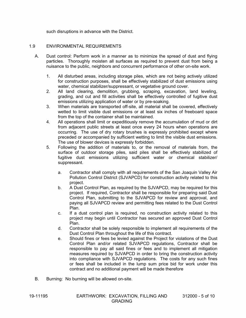
19-11195 EARTHWORK: EXCAVATION, FILLING AND GRADING
312000 - 5 of 10
such disruptions in advance with the District.
1.9 ENVIRONMENTAL REQUIREMENTS
A. Dust control: Perform work in a manner as to minimize the spread of dust and flying particles. Thoroughly moisten all surfaces as required to prevent dust from being a nuisance to the public, neighbors and concurrent performance of other on-site work.
1. All disturbed areas, including storage piles, which are not being actively utilized for construction purposes, shall be effectively stabilized of dust emissions using water, chemical stabilizer/suppressant, or vegetative ground cover.
2. All land clearing, demolition, grubbing, scraping, excavation, land leveling, grading, and cut and fill activities shall be effectively controlled of fugitive dust emissions utilizing application of water or by pre-soaking.
3. When materials are transported off-site, all material shall be covered, effectively wetted to limit visible dust emissions or at least six inches of freeboard space from the top of the container shall be maintained.
4. All operations shall limit or expeditiously remove the accumulation of mud or dirt from adjacent public streets at least once every 24 hours when operations are occurring. The use of dry rotary brushes is expressly prohibited except where preceded or accompanied by sufficient wetting to limit the visible dust emissions. The use of blower devices is expressly forbidden.
5. Following the addition of materials to, or the removal of materials from, the surface of outdoor storage piles, said piles shall be effectively stabilized of fugitive dust emissions utilizing sufficient water or chemical stabilizer/ suppressant.
a. Contractor shall comply with all requirements of the San Joaquin Valley Air Pollution Control District (SJVAPCD) for construction activity related to this project.
b. A Dust Control Plan, as required by the SJVAPCD, may be required for this project. If required, Contractor shall be responsible for preparing said Dust Control Plan, submitting to the SJVAPCD for review and approval, and paying all SJVAPCD review and permitting fees related to the Dust Control Plan.
c. If a dust control plan is required, no construction activity related to this project may begin until Contractor has secured an approved Dust Control Plan.
d. Contractor shall be solely responsible to implement all requirements of the Dust Control Plan throughout the life of this contract.
e. Should fines or fees be levied against the Project for violations of the Dust Control Plan and/or related SJVAPCD regulations, Contractor shall be responsible to pay all said fines or fees and to implement all mitigation measures required by SJVAPCD in order to bring the construction activity into compliance with SJVAPCD regulations. The costs for any such fines or fees shall be included in the lump sum price bid for work under this contract and no additional payment will be made therefore
B. Burning: No burning will be allowed on-site.

19-11195 EARTHWORK: EXCAVATION, FILLING AND GRADING
312000 - 6 of 10
C. Rain: Work under this section shall not be started or maintained under threat of rain, unless the work is not affected by the rain.
D. Do not place fill during weather conditions which will alter moisture content of fill materials sufficiently to make compaction to the specified densities difficult or impossible.
E. When reference is made to SWPPP (Storm Water Pollution Prevention Plan), if any within this Project Manual, then comply with all environmental protection requirements included therein.
F. In accordance with EPA, CARB and CF.
G. Protection:
1. Protect cut and fill areas to prevent water running into excavation. Maintain areas free of water. Remove seeping water immediately by pumps. Provide dewatering as necessary.
2. Protect cut slopes from erosion due to precipitation and other sources of runoff. 3. Protect utilities to remain within the construction area and special construction. If
utility lines are uncovered (water, electric, sewer, etc.) not shown on the drawings during excavation of site, notify the Architect promptly for its review and action.
4. Do not permit access to undeveloped portions of the site, nor to areas that are outside of the limits of grading.
1.10 PROJECT RECORD DOCUMENTS
A. Submit under provisions of GENERAL CONDITIONS and DIVISION 1, GENERAL REQUIREMENTS.
B. Accurately record actual locations of utilities encountered including depth and horizontal location, as measured from permanent site features.
PART 2 - PRODUCTS
2.1 MATERIALS
A. Fill in Turf or Other Planting Areas: Type S2 or S3 per Specification Section SOIL MATERIALS.
B. Fill in Non-planting Areas: Type S1, S2 or S4 per Specification Section SOIL MATERIALS.
C. Imported material: Type S3, S4 or S5 per Specification Section SOIL MATERIALS.
PART 3 - EXECUTION

19-11195 EARTHWORK: EXCAVATION, FILLING AND GRADING
312000 - 7 of 10
3.1 EXAMINATION
A. Verify site conditions.
3.2 PREPARATION
A. Layout of Work:
1. Contractor shall be responsible for all lines and grades. Layout shall be provided by a California registered Land Surveyor or Civil Engineer, at Contractor's expense.
2. Check all bench marks, monuments and property lines and verify locations. 3. Locate and maintain all grade stakes. 4. Monuments moved or displaced during grading operation are to be replaced by a
California Registered Civil Engineer or Surveyor, at Contractor’s expense.
B. Locate, identify, and protect existing above and below grade utilities from damage.
C. Protect plant life, lawns, trees, shrubs, and other features not authorized for removal.
D. Protect existing structures, fences, curbs, sidewalks, paving and other improvements to remain from damage from excavation equipment and vehicular traffic.
E. Employ equipment and methods appropriate to the work site.
F. Protect excavated areas from drainage inflow, and provide for drainage of all excavated areas.
G. Comply with all provisions of the Construction Safety Orders and General Safety Orders of the California Division of Industrial Safety, as well as all other applicable regulations as they pertain to the protection of workers from the hazard of caving ground in excavations.
3.3 SITE STRIPPING:
A. Reference is made to Specification Section SITE CLEARING.
B. Within the areas of planned surface improvements and structures, the near surface soils containing vegetation, roots, organics, or other objectionable material must be stripped and removed from the site. Suitable materials stripped from the site may stockpiled and incorporated into the finish fill for planting areas.
C. All areas to receive surface improvements shall be stripped to remove turf, shrubs, trees and other vegetation, along with associated root systems, concrete, wood, metal, rubbish and other unsuitable debris, and any loose, saturated or unconsolidated soil material. Minimum stripping depth is expected to be 3-inches below existing site grades, or until all organics in excess of 3 percent by volume are removed. Stripping shall continue to the depth required to expose acceptable basement soils that are free from deleterious which are not suitable for Engineered Fill, as required by the Geotechnical Engineer.

19-11195 EARTHWORK: EXCAVATION, FILLING AND GRADING
312000 - 8 of 10
3.4 EXCAVATION
A. Following clearing and stripping operations, over-excavate planned building and structure areas as specified in this Section.
B. Provide additional excavation as required to conform to the lines, grades and cross-sections shown on the plans.
C. When excavating through tree roots, perform work by hand and cut roots, where authorized, with a saw. Remove all roots ¼” in diameter and greater.
D. Remove excess soil not to be used as fill in the Work from the site. Unless requested by Owner to be deposited at a site designated by Owner on the property, obtain a disposal site and legally dispose of said excess material, all at no additional cost to the Owner.
E. Areas disturbed by demolition must be excavated to expose undisturbed soils.
F. Excavated soils free of deleterious substances (organic matter, demolition debris, tree roots, etc.) and with less than 3% organic content by weight, may be returned to the excavations as Engineered Fill.
3.5 FILLING AND COMPACTING
A. Once clearing, stripping and over-excavation operations are complete, scarify the surface to receive fill material or improvements to a depth of 8-inches, moisture condition to within 2% of optimum moisture content, and compact to a minimum of 90% of maximum dry density based on ASTM Test Method 1557.
B. Place and compact soil to finish subgrade of improvements to be placed thereon, or to finished surface grade where no improvements are to be placed thereon.
C. All fill required shall be placed as Engineered Fill.
D. On-site soils are suitable for re-use as Engineered Fill, providing they are cleansed of excessive organics (less than 3 percent by weight, ASTM D2974), debris, and fragments larger than three (3) inches in maximum dimension and meet the requirements of soil Type S4, Specification Section SOIL MATERIALS.
E. Engineered Fill shall be moisture conditioned to within 2% of optimum moisture, placed in uncompacted layers not exceeding eight-inches in thickness, and compacted as specified, based on ASTM Test Method D1557. 1. Non-vegetative surface improvement areas (structures, pavement and site
concrete improvements) - To a minimum of 90% of maximum dry density. 2. Vegetative surface improvement areas (turf and planters) - Below top twelve (12)
inches - to a minimum of 90% of maximum dry density. Top twelve (12) inches - 85% of maximum dry density.
F. Maintain optimum moisture content of fill materials to attain required compaction density.

19-11195 EARTHWORK: EXCAVATION, FILLING AND GRADING
312000 - 9 of 10
G. Additional lifts shall not be placed if the previous lift did not meet the required dry density, or if soil conditions are not stable.
H. Conform fill to the lines, grades and cross-sections shown on the plans.
I. Fill materials to conform to Specification Section SOIL MATERIALS.
J. Provide, at no additional cost to Owner, imported soil material conforming to the requirements of Specification Section SOIL MATERIALS, as needed to attain finished grades of Work.
K. Utilize equipment which will not disturb or damage existing utilities and other improvements.
3.6 PREPARATION OF SUBGRADE FOR SURFACE IMPROVEMENTS
A. Where concrete, asphalt-concrete, aggregate base, or other non-vegetative surface improvements, or a layer of said surface improvements, are to be constructed on the soil surface, prepare the subgrade for said improvements in accordance with this section.
B. Scarify the soil as specified and remove and dispose of (off the project site) all rocks, hardpan chunks or otherwise unsuitable material over 2.5 inches in size.
C. Thoroughly moisture condition and compact as described above.
D. Prior to commencing construction of surface improvements, pass a test roller of size and weight as approved by the Owner over the subgrade to establish the extent of soft or spongy areas requiring repairs.
E. Conform finished subgrade surface to the lines, grades and cross-sections shown on the plans.
3.7 FINE GRADING
A. Fine grade all finished surfaces to the lines, grades and cross-sections shown on the plans, and to blend to hard surface improvements.
B. Rake and smooth all finished surfaces not to receive hard surface improvements.
C. Use suitable stockpiled or imported topsoil for the top 12-inches of areas to receive landscape improvements.
D. Import topsoil meeting the requirements of Specification Section SOIL MATERIALS, as required to complete finish grading.
E. Topsoil may not be used in areas requiring Engineered Fill.
3.8 TOLERANCES

19-11195 EARTHWORK: EXCAVATION, FILLING AND GRADING
312000 - 10 of 10
A. Top surface of Subgrade for Non-Vegetative Surface Improvements or Layers thereof: Plus or minus 0.02 foot from planned elevation.
B. Top surface of Subgrade for Vegetative Surface Improvements or for Bare Ground - Plus or minus 0.05 foot of planned elevation, or as required for finish surface to match adjacent improvements or ground.
3.9 FIELD QUALITY CONTROL
A. Field inspection and testing will be performed under provisions of GENERAL CONDITIONS and/or DIVISION 1, GENERAL REQUIREMENTS.
B. Compaction testing will be performed in accordance with ANSI/ASTM D1557.
C. If tests indicate work does not meet specified requirements, recompact, or remove and replace, and retest.
D. All retesting required as a result of failure of initial test will be performed by Owner’s testing agency, at the expense of the Contractor.
3.10 PROTECTION
A. Protect graded areas from traffic, freezing, erosion, and all other sources of damage. Keep free of debris and trash.
B. Repair and re-establish grades to specified tolerances where completed or partially completed work becomes eroded, rutted, settled, or where it is damaged by subsequent construction operations or weather.
C. Where settlement occurs prior to acceptance of the work, remove and replace surface improvements, excavate, replace, and re-compact in accordance with these specifications, and restore the surface improvements.
3.11 CLEANING
A. Remove all surplus or unsatisfactory soil material, trash, and debris, and legally dispose of off of the Owner’s property.
END OF SECTION

19-11195 SOIL MATERIALS 312222 - 1 of 2
SECTION 312222 SOIL MATERIALS
PART 1 - GENERAL
1.1 SECTION INCLUDES
A. Excavated (and re-used) materials and imported materials.
1.2 RELATED SECTIONS:
A. Section 31 20 00 - Earthwork: Excavation, Filling and Grading.
B. Section 31 23 33 - Trench Excavation and Backfill.
1.3 SUBMITTALS
A. Soil Analysis: Submit for Type S3, S4 and S5 soils to be imported.
B. Materials Source: Submit location of imported materials source. Provide materials from same source throughout the work. Change of source requires approval.
C. For imported soil, obtain DTSC approval prior to importing.
PART 2 - PRODUCTS
2.1 SOIL MATERIALS
A. Soil Type S1: Excavated and re-used material, graded; free of lumps larger than 3 inches, rocks larger than 2 inches, and debris.
B. Soil Type S2: Excavated and reused material, graded; free of roots, lumps greater than one inch, rocks larger than 1/2 inch, debris, weeds and foreign matter.
C. Soil Type S3: Imported topsoil, friable loam; reasonably free of roots, rocks larger than ½ inch, debris, weeds, and foreign matter.
D. Soil Type S4: Imported borrow, suitable for purposes intended, meeting the following characteristics:
1. Maximum Particle Size: 3” Plasticity Index: Less than12
2. Percent Passing #4 Sieve: 65-100 3. Percent Passing #200 Sieve: 20-45 4. Expansion Index: Less than 20 5. R-Value (in paved areas): Minimum 30

19-11195 SOIL MATERIALS 312222 - 2 of 2
6. Low Corrosion Potential:
a. Soluble Sulfates: Less than 1,500 mg/Kgb. Soluble Chlorides: Less than 300 mg/Kgc. Soil Resistivity: Greater than 5,000 ohm-cm
E. Soil Type S5: Imported sand. Natural river or bank sand (sand equivalent greater than30), washed; free of silt, clay, loam, friable or soluble materials, and organic matter.
PART 3 - EXECUTION
3.1 STOCKPILING
A. Stockpile excavated or imported material onsite at location designated by projectinspector.
B. Stockpile excavated or imported material in sufficient quantities to meet projectschedule and requirements.
3.2 STOCKPILE CLEANUP
A. Remove stockpile, leave area in a clean and neat condition. Grade site surface toprevent free standing surface water.
B. Dispose of excess material off-site.
END OF SECTION

19-11195 TRENCH EXCAVATION AND BACKFILL 312333 - 1 of 7
SECTION 312333 TRENCH EXCAVATION AND BACKFILL
PART 1 - GENERAL
1.1 SECTION INCLUDES
A. Excavating trenches, holes and pits for constructing the Work.
B. Backfill and compaction.
C. Providing suitable bedding and backfill material, as specified herein.
1.2 RELATED SECTIONS
A. Contract General Conditions and Division 1, General Requirements.
B. Section 31 11 00 - Site Clearing
C. Section 31 20 00 - Earthwork: Excavation, Filling and Grading
D. Section 31 22 22 - Soil Materials
1.3 REFERENCES
A. ANSI/ASTM D1557 - Test Methods for Moisture-Density Relations of Soils and Soil-Aggregate Mixtures Using 10 lb (4.54 Kg) Rammer and 18 inch (457 mm) Drop.
B. A Geotechnical Engineering Investigation report has been prepared for this project by BSK Associates, BSK Project G18-054-11F, dated March 29, 2018.
1.4 DEFINITIONS
A. Utility: Any buried or above ground pipe, conduit, cable, associate devices or appurtenances, or substructure pertaining hereto.

19-11195 TRENCH EXCAVATION AND BACKFILL 312333 - 2 of 7
1.5 QUALITY ASSURANCE
A. Qualifications
1. Installer:
a. Engage an experienced Installer who has successfully completed three (3) projects of similar scope and size to that indicated for this project within the past 5 years.
B. Regulatory Requirements:
1. In accordance with Specification Section REGULATORY REQUIREMENTS and the following:
a. CARB Materials and equipment used for this Project shall comply with the current applicable regulations of the California Air Resources Board [CARB] and the Environmental Protection Agency [EPA].
b. CM County of Merced, Codes and Ordinances c. EPA Environmental Protection Agency. d. CAL/OSHA Comply with all provisions of the Construction Safety Orders
and the General Safety Orders of the California Division of Occupational Safety and Health, as well as all other applicable regulations as they pertain to the protection of workers from the hazard of caving ground excavations.
C. Certificates:
1. Installer’s certification that all trench backfill installation meets or exceeds the requirements of this specification.
2. Contractor’s certification (on Contractor’s letterhead paper) that the trench backfill materials and installation meets or exceeds the requirements of this specification.
D. Meetings:
1. Pre-Installation: Schedule prior to the start of work.
a. Coordinate the work with other work being performed. b. Identify any potential problems, which may impede planned progress and
proper installation of work regarding quality of installation and warranty requirements.
2. Progress: Scheduled by the Contractor during the performance of the work.
a. Review for proper installation of work progress. b. Identify any installation problems and acceptable corrective measures. c. Identify any measures to maintain or regain project schedule if necessary.

19-11195 TRENCH EXCAVATION AND BACKFILL 312333 - 3 of 7
3. Completion: Scheduled by the Contractor upon proper completion of the work.
a. Inspect and identify any problems which may impede issuance of warranties or guaranties.
4. Maintain installed work until the Notice of Substantial Completion has been filed.
1.6 COORDINATION
A. Coordinate work with Owner’s personnel.
B. Verify that the location of existing utilities have been indicated at work site by utility authorities.
1.7 EXISTING UTILITIES
A. Where subsurface work involves more than the normal depth of excavation required for the removal and/or construction of surface improvements (surface improvements such as concrete work, paving, landscaping, signs, etc.), the Engineer will have made a diligent attempt to indicate on the plans the location of all main and trunkline utility facilities which may affect the Work. In many cases, however, the only available information relative to the existing location of said facilities may have been small scale undimensioned plats. The locations of said facilities, therefore, shall be considered approximate only, until exposed by the Contractor.
B. Under circumstance similar to 31 23 33/1.7A, service laterals and appurtenances will have also been shown where information was available as to their location. In many cases, however, the only available information relative to the existing location of said facilities may have been small scale undimensioned plats. The locations of said facilities, therefore, shall be considered approximate only, until exposed by the Contractor.
C. Determine exact location of existing buried utilities by:
1. Marking on ground or pavement surface the alignment and extent of the proposed facilities and the probable location of existing utilities using construction plans and existing surface features.
2. Requesting Underground Service Alert (USA) to indicate location of existing buried facilities (phone 1-800-227-2608). Provide USA a minimum of two (2) working days notice of request for locations, and notify Owner of said request concurrently.
3. Locate exact location of existing utilities by hand methods of excavation, or by use of vacuum equipment.
D. At proposed work location, expose by hand methods (or vacuum equipment) all existing utilities along the route of the proposed work prior to using any mechanical equipment. If mechanical equipment is allowed at a particular location, it may only be used after the completion by the Contractor of a successful exhaustive search by hand (or vacuum equipment) methods to locate all existing facilities as indicated on the

19-11195 TRENCH EXCAVATION AND BACKFILL 312333 - 4 of 7
plans, and/or as indicated on the ground by USA or Owner’s personnel.
E. Provide Field Engineering per Contract General Conditions and Division 1 to record the location of all utilities encountered. Where locational conflicts exist between existing utilities and the planned location of facilities to be constructed under the Contract, submit detailed information to the Owner’s Inspector and Engineer for review and direction.
F. Maintain all existing utility mains and service lines in constant service during construction of the Work.
G. Where service disruptions are allowed, minimize the length of such disruptions by proper scheduling and diligent pursuit of the work.
PART 2 - PRODUCTS
2.1 FILL MATERIALS
A. Fill Type S1, S2, S4 and S5, as specified in Specification Section SOIL MATERIALS.
PART 3 - EXECUTION
3.1 PREPARATION
A. Protect plant life, lawns, trees, shrubs, and other features not authorized for removal.
B. Protect existing structures, fences, sidewalks, curbs, and other improvements from excavation equipment and vehicular traffic.
C. Maintain and protect above and below grade utilities which are to remain.
D. Comply with all provisions of the Construction Safety Orders and General Safety Orders of the California Division of Industrial Safety, as well as all other applicable regulations as they pertain to the protection of workers from the hazard of caving ground in excavations.
3.2 EXCAVATION
A. Excavate soil required to locate existing utilities and install the work.
B. Use hand methods of excavation to locate existing utilities, and to excavate trenches, pits and holes in congested areas.
C. Employ equipment and methods appropriate to the work site. Small mechanical excavators may be used only in areas where there is sufficient space so as not to damage adjacent improvements, and where the locations of all existing utilities have been determined by hand methods of excavating.

19-11195 TRENCH EXCAVATION AND BACKFILL 312333 - 5 of 7
D. Cut trenches just wide enough to enable installation and proper bedding and backfill, and to allow inspection.
E. Do not interfere with 45 degree bearing splay of foundations.
F. Hand trim excavation. Hand trim for bell and spigot pipe joints. Remove loose material.
G. Excavate trenches, pits or holes bottoming in hardpan to a minimum of 6 inches below the grade for the bottom of the pipe and any couplings, and then backfill to the pipe grade with Type S2, S4 or S5 material, thoroughly compacted. No additional payment will be made for such over-excavation and refill.
H. In all trenches or excavation sites where a firm foundation is not encountered, such as soft, spongy, or otherwise unsuitable material, remove the material to a minimum of 12 inches, or to a depth determined by the Engineer, below the bottom of the proposed pipe or structure, and backfill the space with Type S2, S4 or S5 material containing sufficient moisture to allow compaction to 90% relative compaction. No additional payment will be made for such additional excavation or backfill.
I. Excavate trenches to provide the design grade of the facility, or as directed by the Engineer.
J. Stockpile excavated material to be returned to trench adjacent thereto in location which will not be detrimental to existing improvements, or pedestrian or vehicular traffic. Remove from site all unsuitable or excess material not to be used.
K. When excavating through tree roots, perform work by hand and cut roots, where authorized, with a saw.
L. Remove excess soil not used as backfill from the work site. Obtain a disposal site off of the Owner’s property and legally dispose of said excess material, all at no additional cost to the Owner.
M. If water is encountered during excavations, provide all dewatering measures necessary to construct improvements shown.
N. Contractor shall make all provisions necessary, including but not limited to, shoring or sloping back trench walls as required to address sandy soils. The cost of these provisions shall be included in the lump sum amount bid for this work and no separate payment will be made therefore.
3.3 PROTECTION OF EXCAVATIONS
A. Provide all shoring and bracing as required and those codified in local, state and federal safety regulations.
B. Prevent water, caving or sloughing ground from entering excavations.
C. Maintain excavations free of water.

19-11195 TRENCH EXCAVATION AND BACKFILL 312333 - 6 of 7
3.4 BACKFILLING
A. Provide type S2 or S5 pipe bedding as required by Plans and compact to 90% of the maximum dry density. Bedding shall be a minimum of six-inches below pipes equal to or greater than twelve-inches in diameter and a minimum of four-inches below pipes less than twelve-inches in diameter.
B. After installation of pipes and appurtenances and placement of pipe bedding material, backfill trenches and excavations to finished grade, or subgrade in areas to receive surface improvements.
C. Pipe bedding material and envelope six-inches above the pipe shall consist of sand with a sand equivalent (SE) greater than 30.
D. Backfill trenches above pipe bedding and envelope material and to within 24 inches of finish subgrade with Type S1, S2, S4 or S5 soils, except that that top 12 inches shall be type S2, S3, S4 or S5 soils.
E. Employ a placement method that does not disturb or damage existing or proposed pipes or other Utilities or Improvements.
F. Place and compact all soil backfill in continuous layers not exceeding 8 inches in uncompacted thickness.
G. Maintain optimum moisture content of fill materials to attain required compaction density.
H. Backfill final 12-inch thickness to finish subgrade in areas to receive concrete, asphalt-concrete, aggregate base, or other non-vegetative surface improvement, with Type S2, S4 or S5 soils.
I. Backfill final 12-inch thickness to finish subgrade in areas to receive sod, other vegetation, or bare soil, with Type S2 or S3 soils.
J. Compact backfill below the top 12-inches to 90% relative compaction.
K. In areas to receive buildings, structures, or concrete flatwork, compact the top 12-inches to 90% relative compaction.
L. In areas to receive asphalt concrete pavements, compact the top 12-inches to 95% relative compaction.
M. In planting areas, compact the top 12-inches to 85% relative compaction.
3.5 TOLERANCES
A. Top Surface of Backfill under Paved or Concrete Areas: Plus or minus 0.02 feet from required elevations.
B. Top Surface of General Backfilling: As required for finish surface to match adjacent improvements or ground.

19-11195 TRENCH EXCAVATION AND BACKFILL 312333 - 7 of 7
3.6 FIELD QUALITY CONTROL
A. Field inspection and testing will be performed under provisions of General Conditions and/or Division 1.
B. Compaction testing will be performed in accordance with ANSI/ASTM D1557.
C. If tests indicate work does not meet specified requirements, recompact, and retest. Retests required due to failure of initial tests shall be paid for by the Contractor.
3.7 PROGRESS AND PROSECUTION
A. Backfill any excavation opened in any day on that same day.
END OF SECTION


19-11195 ASPHALT PAVING 321216 - 1 of 5
SECTION 321216 ASPHALT PAVING
PART 1 - GENERAL
1.1 SECTION INCLUDES:
A. Asphaltic-concrete paving.
B. Seal Coat.
1.2 RELATED SECTIONS:
A. Section 31 22 00 - Earthwork: Excavation, Filling, and Grading
B. Section 31 23 00 - Trench Excavation and Backfill.
C. Drawings and general provisions of Contract, including General and Supplementary Conditions and Division-1 Specifications sections, apply to the work of this section.
1.3 REFERENCES
A. SSCDOT - Standard Specifications, Department of Transportation, State of California (Caltrans), latest edition, except for references to method of payment, and references to any state furnished materials.
1.4 QUALITY ASSURANCE
A. Perform work in accordance with SSCDOT.
B. Mixing Plant: Conform to SSCDOT.
C. Installation Criteria: Asphalt concrete shall show no evidence of cracking, uneven settlement, improper drainage, or untoward junctions with adjoining or existing surfaces. Work displaying such conditions shall be corrected under the Contractor’s guarantee of all work.
1.5 SUBMITTALS
A. Submit under provisions of Division 1 - General Requirements.
B. Certificates of compliance for material.
C. Load tags for delivered material.
1.6 COORDINATION
A. Coordinate with other work, including subgrade preparation and soil sterilization.

19-11195 ASPHALT PAVING 321216 - 2 of 5
1.7 ENVIRONMENTAL REQUIREMENTS
A. Do not place asphalt-concrete when atmosphere temperature is less than 50 degrees F, or surface is wet or frozen.
PART 2 - PRODUCTS
2.1 MATERIALS
A. Paint Binder: In accordance with SSCDOT Section 94, Asphaltic Emulsions. B. Asphalt-Concrete: Type B in accordance with Section 39, SSCDOT, ½ inch
maximum aggregate (medium). The asphaltic concrete should be compacted to a minimum compaction of 95 percent of the laboratory tested maximum density as determined by California Test Method 366. Use asphalt binder performance grade PG 64-10.
C. Seal Coat: Asphalt based seal coat shall be "Guardtop" as manufactured by
Industrial Asphalt, Irwindale, California, or approved equal.
PART 3 - EXECUTION
3.1 EXAMINATION
A. Verify quantities required. New asphalt-concrete paving is required at all locations shown on the plans, and where existing asphalt-concrete paving to remain is removed or damaged by the Project excavation or related work.
B. Verify that subgrade has been compacted to required relative compaction and is
dry. C. Verify gradients and elevations of base are correct. D. Verify that subgrade has been sterilized per 31 31 00.
3.2 AGGEGATE BASE
A. Where shown on the construction plans, place and compact aggregate base course per Section 321126.
B. Where shown on the construction plans, place asphalt on compacted earth
subgrade per Section 312000 and 312300. C. A soil sterilant shall be applied over the entire area, which is to be paved.
3.3 PREPARATION - PAINT BINDER

19-11195 ASPHALT PAVING 321216 - 3 of 5
A. Apply paint binder to existing asphalt-concrete or concrete surfaces which will be in contact with asphalt-concrete surfacing.
B. Rate of application for all surfaces against which asphalt concrete is to be placed
shall be no less than 0.02 and no more than 0.05 gallons per square yard. All vertical concrete surfaces which will be in contact with asphalt concrete surfacing and all areas now in place which will be covered with new surfacing materials and feathering operations shall be coated with a paint binder applied at the rate of 0.05 gallons per square yard.
3.4 INSTALLATION OF ASPHALTIC-CONCRETE
A. Install in conformance with SSCDOT Section 39, Asphalt-Concrete. B. Thickness - As shown on construction plans. Where thickness exceeds 2 inches,
place in no less than 2 layers with top layer no thicker than one inch. Asphaltic concrete shall be laid to the thickness designated on the Plans. The plan thickness is to be considered as a minimum thickness. The Contractor shall lay the asphaltic concrete to a depth required to insure that, after compaction, the in place compacted thickness is equal to or greater than the specified plan thickness.
C. The Contractor shall provide to the Engineer the truck delivery weight tags for the
asphaltic concrete material. The quantity delivered shall be equal to or greater than the calculated in place quantity based on the specified thickness and area to be paved as designated on the construction plans and based on a unit density of the asphaltic concrete of 141 pounds per cubic feet.
D. Asphalt type: PG 64-10 E. Compaction Equipment - In accordance with Section 39, SSCDOT. At small difficult
areas, equipment may be altered as approved by Engineer. F. The completed surface shall be thoroughly compacted, free from ruts, depressions,
and irregularities and to be true to grade and cross-section.
3.5 INSTALLATION OF SEAL COAT
A. Immediately prior to applying the sealer, the surface shall be cleaned of all loose material which might adversely affect bonding of the sealer. Any standard cleaning method such as power sweepers and blowers may be employed.
B. Where cracks exceed 1/2 inch in depth of 1/4 inch in width, or both, they shall be
thoroughly cleaned and repaired with asphalt crack filler material before placing the sealer. All cracks between 1/8" and 1/4" in width shall be filled with "Guardtop Crackfiller", as manufactured by Industrial Asphalt, or approved equal, in accordance with the manufacturer's recommendations.
C. Whether or not specifically indicated on the plans, all potholes and badly distorted
or depressed areas, except those lying within areas designated for pavement removal and replacement, shall be properly cleaned and repaired by applying a binder coat and hot mix asphalt concrete patch conforming to the requirements of Section 39, SSCDOT, before placing the seal coat. Any vegetation such as soil

19-11195 ASPHALT PAVING 321216 - 4 of 5
sterilant approved by the Engineer shall be applied to the area and any required pavement patching shall then be completed.
D. A prime coat of SS-1 asphalt emulsion diluted with water, to 5 parts water to 1 part
asphaltic emulsion, shall be applied to all existing (not new) pavement surfaces at a rate of application of 0.05 to 0.10 gallon of diluted primer per square yard.
E. Following the prime coat, two coast of asphalt based seal coat shall be applied.
The first coat shall have added to it a silica sand mineral filler, which has passed a 50-mesh screen, at a rate of 2 to 3 pounds per 1 gallon of concentrated sealer. When the first coat is dry enough to walk on without picking the material up, a second coat shall be applied without mineral filler. If the manufacturer indicates that the product may be diluted, it may be diluted with no more than 20 percent by volume clean fresh water with the prior approval of the Engineer. The total application rate shall be a minimum of 35 to 45 gallons of undiluted product per 1,000 square feet, as directed by the Engineer. The finished surface shall be smooth and uniform in appearance. If existing depressions are such that aggregate still protrudes after the second coat of asphalt based sealer has been applied, the Contractor shall apply a third coat when so directed by the Engineer.
1. Seal Coat (for existing pavement) - 35 to 40 gallons of undiluted product per 1,000 square feet, as directed by the Engineer.
F. Allow asphalt-concrete to cure 21 days minimum prior to sealing. G. Broom clean asphalt-concrete prior to sealing. H. Protect sealed surface until it is cured.
3.6 TOLERANCES - GENERAL
A. Flatness: Maximum variation of 1/4 inch measured with 12-foot straight edge. B. Scheduled Compacted Thickness: No less than specified.
3.7 FIELD QUALITY CONTROL
A. Field inspection and testing will be performed under provisions of Section 014523. B. Pavement shall comply with the following:
1. Water shall not be able to accumulate at any point and the surface shall be free to drain to drainage inlets.
2. The paving contractor shall water flood the surface with the use of a water truck. If, after 30 minutes on a 70 degree F day, “bird baths” are evident in a depth more than 0.01 foot, the paving contractor, track surfacing manufacturer and the Owner’s representative will determine the best method of correction.
3. A string line and a 10 foot straightedge shall be used to check for high spots and ridges. High spots and ridges out of compliance shall be reduced by a remedy determined by the paving contractor and the Owner’s representative.

19-11195 ASPHALT PAVING 321216 - 5 of 5
C. Should a section of the work be not acceptable on the basis of inadequate compaction and/or the mixture becomes loose and broken, mixed with dirt, out of tolerance, or in any other way defective, it shall be repaired or removed and replaced with fresh mixture and immediately compacted to conform to the surrounding area to the satisfaction of the Owner.
3.8 PROTECTION
A. Immediately after placement, protect pavement from mechanical injury. B. Allow asphalt-concrete to cure 21 days minimum prior to placement of seal
coat. C. Broom clean asphalt-concrete prior to sealing. D. Protect sealed surface until it is cured.
END OF SECTION


19-11195 SITE CONCRETE IMPROVEMENTS 321313 - 1 of 4
SECTION 321313 SITE CONCRETE IMPROVEMENTS
PART 1 - GENERAL
1.1 SECTION INCLUDES
A. Provide all material, labor, equipment and services necessary to completely installexterior Portland cement flatwork, cast-in-place concrete, and architectural flatworkconcrete, accessories and other related items, slabs, ramps and sidewalks andwalkways, curb and gutter, mowstrips, and other miscellaneous concrete items of theform and dimensions shown on the plans and necessary to complete the project, andin accordance with the requirements of the Standard Specifications as modified andsupplemented by these Special Provisions
B. Drawings and general provisions of Contract, including General and SupplementaryConditions and Division-1 Specifications sections, apply to the work of this section.
1.2 RELATED SECTIONS:
A. Section 32 13 15 - Concrete Reinforcement
B. Section 31 20 00 - Earthwork: Excavation, Filling, and Grading
1.3 REFERENCES
A. SSCDOT - Standard Specifications, Department of Transportation, State of California(Caltrans), latest edition, except for references to method of payment, and referencesto any state furnished materials.
B. ACI standards, including but not limited to #304, 305, 306, 308, 309 and 347.
C. ASTM standards, including but not limited to #C-33, C-39, C-94, C-136, C-143, C-150,and C-309.
1.4 QUALITY ASSURANCE
A. Furnish concrete materials conforming with SSCDOT.
B. Perform work in accordance with SSCDOT, unless noted otherwise herein.
1.5 SUBMITTALS
A. Submit under provisions of Specification Section SUBMITTALS.

19-11195 SITE CONCRETE IMPROVEMENTS 321313 - 2 of 4
1. Certificates of compliance for materials and mix designs. 2. Load tags for delivered material. 3. Strength testing as required by the approving agency. 4. Integral color sample, where applicable. 5. Application instructions for the architectural finish materials. 6. Accessories and manufacturer’s installation specifications.
PART 2 - PRODUCTS
2.1 MATERIALS
A. Concrete shall be 6-sack conforming to the requirements of Section 90 of the Standard Specifications, and shall have a minimum compressive strength of 3,500 psi at 28 days. Portland cement shall be Type II Modified and aggregate gradation shall conform to the requirements of Subsection 90-3.4 for 1-inch maximum grading.
B. Reinforcement shall comply with relevant portions of Specification Section CONCRETE REINFORCEMENT.
PART 3 - EXECUTION
3.1 PREPARATION
A. Subgrade shall conform to the requirements of Specification Section EARTHWORK. The District may elect to verify compacted subgrade elevations by measurement made from adjacent existing improvements or by a template supported by forms.
3.2 GENERAL CONCRETE
A. Concrete placement shall conform to the applicable requirements of Standard Specification Sections 51 and 90. Concrete shall not be placed when the air temper-ature in the shade at the project site exceeds 95º F or is below 45º F, or when the temperature of the concrete exceeds 85º F.
B. After the concrete has been placed, it shall be struck off to proper section and compacted with a grid of parallel metal bars until a layer of mortar not less than 3/8 inch thick has been brought to the surface. All exposed concrete surfaces shall receive a medium broom finish applied transversely to the line of pedestrian traffic or to the longest dimension of the concrete, as applicable.
C. General concrete surfaces shall be cured by the curing compound method and shall be protected in accordance with the provisions of Subsections 90-7 and 90-8 of the Standard Specifications.

19-11195 SITE CONCRETE IMPROVEMENTS 321313 - 3 of 4
3.3 PROTECTION OF CONCRETE
A. The Contractor shall be responsible for the condition of all concrete work until suchtime as all work has been completed and is accepted by the Owner. The Contractorshall limit vehicular travel across concrete until such time as the concrete has achievedstrength sufficient that it can support traffic without damage. In no case, however, willvehicles be allowed to travel across new concrete improvements until seven calendardays have passed since the concrete was placed.
3.4 CONCRETE JOINTS
A. Expansion joints and weakened plane joints shall be constructed at the locationsshown on the plans or as directed by the Engineer. Where joint locations are notspecified on the plans, expansion joints shall be constructed at maximum intervals of45 feet, and weakened plane joints shall be constructed at maximum intervals of 15feet.
B. Expansion joints shall be considered as weakened plane joints for the purpose ofspacing weakened plane joints. Expansion joints shall be tooled with a ½ inchmaximum radius edger, and shall be filled with ½ inch pre-formed expansion joint filler.
3.5 CONCRETE FINISHES
A. Where concrete is being installed adjacent to or near existing concrete improvements,match the finish of similar concrete surfaces, i.e. new sidewalks shall match existingsidewalks, new curbs shall match existing curbs, etc.
B. Sidewalks and Mowstrips: Medium sweat finish or medium broom finish as required tomatch existing finishes.
C. Curbs: Trowel smooth and finish with a light brush.
D. Gutters: Medium broom finish
E. Drive approaches and wheelchair ramps: Broom Finish, perpendicular to the directionof travel
3.6 INSTALLATION OF ACCESSORIES
A. Strictly comply with manufacturer's instructions and recommendations and approveddetails. Securely anchor work to substrate.

19-11195 SITE CONCRETE IMPROVEMENTS 321313 - 4 of 4
3.7 REPAIR AND CLEAN-UP
A. Contractor shall legally remove all trash, debris, containers and excess materials from the site on a periodic basis, and shall keep the work broom clean until Owner’s acceptance.
B. The Contractor shall be held responsible for the repair and/or replacement of new or existing improvements damaged as a result of this work to the satisfaction of the Owner.
C. The Contractor shall provide roll-off bins for wash-out of ready mix concrete trucks and pumpers. Do not allow concrete debris or cement water onto soils scheduled for landscape planting.
END OF SECTION

19-11195 CONCRETE REINFORCEMENT 321315 - 1 of 2
SECTION 321315 CONCRETE REINFORCEMENT
PART 1 - GENERAL
1.1 RELATED DOCUMENTS
A. Contract General Conditions and Division 1 Specifications.
B. Section 32 13 13 - Site Concrete Improvements.
C. Section 04 22 00 - Concrete Unit Masonry
1.2 SUBMITTALS
A. Submit in accordance with Specification Section SUBMITTALS and the Contract General Conditions.
1. Mill test certificates identifying chemical and physical analysis of each load of reinforcing steel delivered. If mill test reports are not available and the quantity of steel for a structure exceeds 5 tons, provide a laboratory test to prove yield strength and bending.
2. Drawings and placing diagrams for each grade slab including dowels and corner bars.
3. On the placing diagrams, show all openings for pipelines and architectural features. Include additional reinforcing at openings and corner bar arrangements at intersecting beams, walls, and footings.
4. Coordinate placing diagrams with the concrete placing schedule.
1.3 PRODUCT DELIVERY
A. Deliver reinforcement to project site in bundles marked with tags indicating bar size and length.
B. Store on wooden supports above ground surface.
PART 2 - PRODUCTS
2.1 BARS
A. Bars shall be deformed billet steel conforming to ASTM A 615, Grade 40. Mixing of steel grades will not be allowed.

19-11195 CONCRETE REINFORCEMENT 321315 - 2 of 2
2.2 BAR SUPPORTS
A. Bar support shall be concrete or metal chairs, spacers or hangers. Reinforcing barsshall not be supported by forms.
2.3 TIE WIRE
A. Tie wire shall be annealed steel wire of not less than 16-gauge.
PART 3 - EXECUTION
3.1 PLACEMENT
A. Position reinforcement in accordance with the drawings, secure with wire ties orsuitable clips at all intersections, and support by an adequate number of concrete ormetal chairs, spacers, or metal hangers such that reinforcing bars do not sag morethan one quarter of an inch (1/4”) between supports. Do not place reinforcement orsupports in contact with the forms. Bend tie wires away from the forms in order toprovide the specified concrete coverage. To secure reinforcement in position, theContractor may elect to locate bars additional to those shown on the drawings, but atno additional cost to the Owner.
B. Set reinforcing dowels and anchor bolts in place prior to placing concrete. Do notpress them into the concrete after the concrete has been placed.
3.2 SPLICES
A. Splice bars only at locations shown on the drawings. Where splices are not detailed,lap bars 36 bar diameters and 18 inches minimum and stagger adjacent splices 48 bardiameters.
3.3 CLEANING
A. Remove dirt, form oil, excessive rust, cement coating from previous pours, and foreignmatter that will reduce bond with concrete.
3.4 PROTECTION DURING CONCRETING
A. Keep reinforcing steel in proper position during concrete placement.
END OF SECTION