Public Works Department Standards
227
-
Upload
khangminh22 -
Category
Documents
-
view
2 -
download
0
Transcript of Public Works Department Standards


Table of Contents Section Number Page Number
i
1. Introduction 1 1-1. Introduction
1-1.1. Purpose 1 1-1.2. Johnson City Public Works Standard Document 1
1-2. Responsibility of the Professional Designer 1 1-3. Other Standards Which May Apply 1
2. Plan Requirements 3 2-1. General Layout 3 2-2. Technical Specifications 3 2-3. Standard Drawings 3 2-4. Standard Notes 3 2-5. Right-of-way Plans 3 2-6. Construction Plans 3
2-6.1. Organization of Plans 3 2-6.2. Cover Sheet, sheet number 1 3 2-6.3. Sheet for the List of Quantities and Tabulation Tables 4 2-6.4. Standard Drawing Sheet 4 2-6.5. Details Sheet 4 2-6.6. Right-of-Way Sheet 4 2-6.7. Present Layout and Right-of-Way Sheets 4 2-6.8. Proposed Layout Sheets 5 2-6.9. Profile Sheets 5 2-6.10. Cross-section sheets 5 2-6.11. Miscellaneous Sheets Which are Required 5 2-6.12. Miscellaneous Sheets Which May be Required 6
2-7. Review Requirements 6 2-7.1. General 6 2-7.2. Subdivision Plans 6 2-7.3. Site Plans 6 2-7.4. Public Street Improvement Plans 6 2-7.5. Preliminary Submittals 6 2-7.6. Approval of Construction Plans 6
3. Streets 7 3-1. General 7 3-2. Earth Work Requirements 7
3-2.1. Grading Right-of-Way 7 3-2.2. Side Slopes and Embankments 7 3-2.3. Roadway Subgrade 7 3-2.4. Trenching 7
3-3. Cross Sections 8 3-4. Design Speed and Sight Distance 8
3-4.1. For Residential Streets 8 3-4.2. For Non-residential Streets 8
3-5. Alignment 8 3-5.1. Horizontal Alignment 8 3-5.2. Vertical Alignment 8

Table of Contents Section Number Page Number
ii
3-5.2.A. Street Grades 9 3-5.2.B. Grade at Intersections 9
3-6. Pavement Design 9 3-6.1. General 9 3-6.2. Minimum Number of Soil Samples 9 3-6.3. Minimum Required Soil Tests 9 3-6.4. Minimum Pavement Section 9
3-7. Curb and Gutter Section 12 3-8. Storm Water Manholes or Catch Basins 12 3-9. Sidewalks / Multipurpose Paths, and Bicycle Paths 12
3-9.1. Sidewalks and Multipurpose Paths 12 3-9.2. Bicycle Paths 13
3-10. Medians 13 3-11. Safety Features 13
3-11.1. General 13 3-11.2. Embankment 14 3-11.3. Fixed Objects 14 3-11.4. Vertical Clearance 14 3-11.5. Lateral Clearance 14
4. Transportation 15 4-1. Traffic Impact Study Requirements 15
4-1.1. Criteria for a Traffic Impact Study 15 4-1.1.A. Adjacent Roadway ADT 15 4-1.1.B. Minimum Peak Hour Volume 15 4-1.1.C. Previous Traffic Studies 15
4-1.2. Preliminary Traffic Impact Study 15 4-1.3. Responsibility for the Traffic Impact Study 15 4-1.4. Preparation of the Traffic Impact Study 15 4-1.5. Coordination with the City 15
4-2. Traffic Impact Study Format 15 4-2.1. Study Requirements 16 4-2.2. Introduction 16 4-2.3. Site Location and Zoning 16 4-2.4. Study Area Boundaries 16 4-2.5. Existing Area Street System Description 16 4-2.6. Existing and Projected Roadway & Intersection Volumes 16 4-2.7. Existing and Proposed Site Uses 16 4-2.8. Existing and Proposed Land Uses in Vicinity of Site 16 4-2.9. Travel Demand Management Strategies 17 4-2.10. Trip Generation 17
4-2.10.A. Summary Table 17 4-2.10.B. Calculations 17
4-2.11. Trip Generation Reductions 18 4-2.12. Trip Distribution/Assignment and Modal Split 18
4-2.12.A. Trip Distribution 18 4-2.12.B. Trip Assignment 18
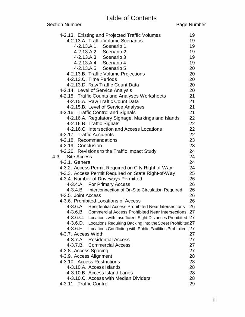
Table of Contents Section Number Page Number
iii
4-2.13. Existing and Projected Traffic Volumes 19 4-2.13.A. Traffic Volume Scenarios 19 4-2.13.A.1. Scenario 1 19 4-2.13.A.2 Scenario 2 19 4-2.13.A.3 Scenario 3 19 4-2.13.A.4 Scenario 4 19 4-2.13.A.5 Scenario 5 20 4-2.13.B. Traffic Volume Projections 20 4-2.13.C. Time Periods 20 4-2.13.D. Raw Traffic Count Data 20
4-2.14. Level of Service Analysis 20 4-2.15. Traffic Counts and Analyses Worksheets 21
4-2.15.A. Raw Traffic Count Data 21 4-2.15.B. Level of Service Analyses 21
4-2.16. Traffic Control and Signals 21 4-2.16.A. Regulatory Signage, Markings and Islands 22 4-2.16.B. Traffic Signals 22 4-2.16.C. Intersection and Access Locations 22
4-2.17. Traffic Accidents 22 4-2.18. Recommendations 23 4-2.19. Conclusion 23 4-2.20. Revisions to the Traffic Impact Study 24
4-3. Site Access 24 4-3.1. General 24 4-3.2. Access Permit Required on City Right-of-Way 24 4-3.3. Access Permit Required on State Right-of-Way 25 4-3.4. Number of Driveways Permitted 26
4-3.4.A. For Primary Access 26 4-3.4.B. Interconnection of On-Site Circulation Required 26
4-3.5. Joint Access 26 4-3.6. Prohibited Locations of Access 26
4-3.6.A. Residential Access Prohibited Near Intersections 26 4-3.6.B. Commercial Access Prohibited Near Intersections 27 4-3.6.C. Locations with Insufficient Sight Distances Prohibited 27 4-3.6.D. Locations Requiring Backing into the Street Prohibited 27 4-3.6.E. Locations Conflicting with Public Facilities Prohibited 27
4-3.7. Access Width 27 4-3.7.A. Residential Access 27 4-3.7.B. Commercial Access 27
4-3.8. Access Spacing 27 4-3.9. Access Alignment 28 4-3.10. Access Restrictions 28
4-3.10.A. Access Islands 28 4-3.10.B. Access Island Lanes 28 4-3.10.C. Access with Median Dividers 28
4-3.11. Traffic Control 29

Table of Contents Section Number Page Number
iv
4-3.12. One-Way Access Lanes 29 4-3.13. Speed Change Lanes 29
4-3.13.A. Acceleration Lanes 29 4-3.13.B. Deceleration Lanes 29 4-3.13.C. Additional Lanes 30 4-3.13.D. Vehicle Storage 30
4-3.14. Construction Details 30 4-4. Traffic Control Devices 30
4-4.1. Traffic Signs and Pavement Markings 30 4-4.1.A. Required 30 4-4.1.B. Signing and Striping Plan 30 4-4.1.C. Conformance with MUTCD 30 4-4.1.D. Materials 30
4-4.2. Traffic Signals 31 4-4.2.A. Required 31 4-4.2.B. Traffic Signal Plan 31 4-4.2.C. Conformance with MUTCD 31 4-4.2.D. Materials 31
4-5. Street Lighting 31 4-5.1. Subdivisions 31 4-5.2. Other Developments 32 4-5.3. City Street Improvement Projects 32 4-5.4. Downtown Cultural District 32
4-6. Construction Zone Traffic Control 32 4-6.1. Plan Required 32 4-6.2. Conformance with MUTCD 32 4-6.3. Responsibility for Design 32
5. Storm Water Management 33 5-1. Storm Water Management Design 33
5-1.1. Design Report Format 33 5-1.2. Calculations and Determinations 33
5-1.2.A. Runoff Calculations 33 5-1.2.B. Line Sizing 33 5-1.2.C. Detention of Storm Water 33 5-1.2.D. Erosion and Sediment Control Calculations 33 5-1.2.E. Design Date For Stream-Crossing Structures 33
5-1.3. Adequate Drainage Systems 33 5-1.4. Minor Drainage Systems 33 5-1.5. Major Drainage Systems 33 5-1.6. Open Channels 35
5-1.6.A. Channel Capacity 35 5-1.6.B. Lined Channels 35 5-1.6.C. Grassed Channels 35
5-1.7. Storm Water Detention / Retention 35 5-1.7.A. Detention Required 35 5-1.7.B. Release Rate 35

Table of Contents Section Number Page Number
v
5-1.7.C. Alternate Drainage 35 5-1.7.D. Minimum Requirements for Detention Basins 36 5-1.7.E. Outlet Protection 37 5-1.7.F. Drawdown 37 5-1.7.G. Maintenance 37
5-2. Erosion and Sediment Control 37 5-2.1. Erosion and Sediment Control Plan Required 37 5-2.2. Responsibility for Designing Plan 37 5-2.3. Minimum Standards 38
5-3. Floodplain / Sinkhole Regulation 38 5-3.1. General 38 5-3.2. Permit Required 38 5-3.3. Responsibility for Design 38 5-3.4. Minimum Standards 38
5-4. Other Agency Regulations 38 5-4.1. TDEC 38 5-4.2. Army Corps of Engineers / TVA Joint Permit 39
5-5. System Maintenance 39 6. Standard Drawings 40 7. Appendix 41
7-1. Technical Specifications 41 7-2. Development Regulations 41 7-3. Pavement Design Nomographs 41 7-4. Driveway Ordinance 41
7-4.1. Chapter 21, Article III. Driveways 41 7-4.2. Ordinance No. 5482, State of Franklin Road 41
7-5. TDOT Entrance Regulations 41 7-6. Site Lighting Ordinance 41 7-7. Storm Water Management Ordinance 41 7-8. Erosion and Sediment Control Ordinance 41 7-9. Floodplain / Sinkhole Ordinances 41 7-10. Johnson City GPS Reference System 41

1
1. Introduction
1-1.1. The Purpose for a Johnson City Public Works Standards Document
In May 1997 the Johnson City Regional Planning Commission completed an updating of the Subdivision Regulations. In these updated regulations a “Johnson City Public Works Department’s Standards” document was referenced for the first time. The Planning Commission had reduced the content of the Subdivision Regulations, removing technical text and graphics relating to the standard design of streets and drainage systems. The new Johnson City Public Works Department’s Standards would include this information and other additional information from other City Codes and policies, and become the instrument for documenting minimum criteria for designing and constructing both private and public facilities within Johnson City and the jurisdiction of the Johnson City Regional Planning Commission.
1-1.2. The Johnson City Public Works Standards Document
This document is the standards manual referenced by the Subdivision Regulations. The minimum standards within this manual are intended to assist the licensed professional in understanding the requirements of the Johnson City Public Works Department and to provide a consistent means of relating those requirements to the designer. These standards are judged to be the minimum standards that are necessary to protect the public health, safety, and welfare; and they should be used as a guide in preparing construction plans for the facilities covered in the manual. The review and approval process by the City, in accordance with these regulations, is not in any way to be construed as assisting in the design of any project.
1-2. The Responsibility of the Professional Designer and Use of the Johnson City
Public Works Standards Document The minimum standards stated within should not be construed as a limit on the professional designer. Tennessee State law requires the professional designer to protect the public health, safety, and welfare, and to practice only within the professional designer’s area of competence. The City of Johnson City requires that all construction plans submitted for approval be certified by stamping and properly validating the professional seal of the licensed engineer, licensed land surveyor, or licensed architect. When multiple professional designers combine services to produce a complete set of plans, each professional designer will certify the section of the plans for which the professional designer is responsible. Therefore, it is not uncommon to have more than one certification on a set of construction plans.
1-3. Other Standards Which May Apply
Compliance with the standards included in this manual may not fulfill all of the necessary requirements and conditions to pursue a development project. Water and Sewer design standards, for example, are published in a separate

2
document and copies are available from the Water and Sewer Engineering and Traffic Engineering Divisions of the City of Johnson City. Also, State and Federal agencies’ regulations may require certain approvals and permits, and permit information from each State and Federal agency must be obtained separately. A separate document, An Outline of Development Regulations, is intended to be a comprehensive outline of the procedures necessary to fulfill all requirements and conditions of obtaining approval prior to proceeding with a development project. A copy of the Outline of Development Regulations is included in the Appendix, Section 7-2, of this document.

3
2. Plan Requirements
2-1 . General Layout All roadway construction plans shall comply with the T-DOT format for roadway construction plans. Some exemptions are made for subdivision and private development site plans as specified in the following discussion.
2-2 . Technical Specifications Construction workmanship and quality of construction materials shall be as specified in the latest edition of the Tennessee Department of Transportation Standard Specifications for Road and Bridge Construction unless otherwise specified in this document.
2-3 . Standard Drawings
The Tennessee Department of Transportation Standard Roadway and Structure Drawings manual of latest revision shall be utilized in the design of subdivision, public, and private development unless otherwise specified in this document.
2-4 . Standard Notes
The Standard Notes of latest revision, as published in the Tennessee Department of Transportation Design Guidelines shall be used, as they would apply to the type of construction being specified in the plans.
2-5. Right-of-way Plans When required, right-of-way plans shall conform to the T-DOT right-of-way plan format, as specified in the T-DOT Design Guidelines.
2-6. Construction Plans 2-6.1. Organization of Plans:
A. Sheets shall be arranged per the list in this section, B. The standard symbols specified by T-DOT shall be used to
represent different existing and proposed features on the plan sheets. These symbols are shown in the front section of the T-DOT Standard Roadway and Structures Drawings manual. Each sheet that follows the cover sheet shall be numbered in the upper right corner.
C. Preferred scales for the Present and Proposed Layout Sheets are 1”= 50’, 1”= 40”, or 1”= 20’.
2-6.2. Cover Sheet, sheet number 1: The construction plans shall have a cover sheet containing: A. A project name, B. A location map scaled to no less than 1’ = 1000 feet, C. Subdivision, area, or institution to be served, D. The name and address of the professional designer, or the
professional design firm,

4
E. Current and projected ADT, design hour volume, and design speed, F. The current date, and G. The revision date, if the plans have been revised during the review
process.
2-6.3. Sheet for the List of Quantities and Tabulation Tables: Subdivisions and plans for private development will be exempt from providing this sheet. Following the cover page, a sheet will be provided which will list the estimated quantities and show applicable footnotes associated with individual construction items. Tables consisting of drainage structures and pipe sizes may be included on this sheet. Other sheets may be provided when room is insufficient on the first sheet of this section. Other construction items, which require tabulation, shall be included in this section.
2-6.4. Standard Drawing Sheet: When T-DOT standard drawings will depict construction items being specified, a list of standard drawing numbers may be substituted on a plan sheet following the cover sheet. If T-DOT has made a revision to the standard drawing being specified, then the effective date of T-DOT’s revision will be shown along with the standard drawing number.
2-6.5. Details Sheet: Details, which are not included in the T-DOT Standard Roadway and Structures Drawings notebook, shall be shown following the list of applicable standard drawings.
2-6.6. Right-of-Way Sheet: Subdivisions and plans for private development will be exempt from providing this sheet. When right-of-way will be acquired, a sheet will be provided with a right-of-way index map at a scale that will show effective detail. The corresponding tract numbers shall be listed on each tract. If room allows, a T-DOT style right-of-way table shall be included. If necessary, the right-of-way table may be included on a separate sheet.
2-6.7. Present Layout and Right-of-Way sheets: A. Subdivisions and plans for private development will be allowed to
vary some from this format. However, to preserve a degree of compliance to a standard style, subdivision and private development construction plans should follow this pattern as close as possible. Refer to the Appendix, Section 7-2, Outline of Development Regulations, 11.3.3, “Major Final Site Plan Approval”, page 7 of 18 for a description of what shall be included on a site plan.
B. Site plans for private development shall include existing contour lines at 2-foot intervals, and if this sheet is to be a grading plan, include the proposed contour lines at 2-foot intervals.
C. A plan view of the present topographic features of the area under construction shall be shown on this sheet. If the sheet will become cluttered with the standard topographic and proposed right-of-way

5
information, a second sheet may be included for the right–of-way information.
D. The proposed right-of-way sheet shall conform to the style used by T-DOT.
E. Topographic features to be shown on the present layout sheet are not to be limited to the following, but this list is to provide a minimum example: 1. Centerline of the proposed street with station numbers, 2. Edge of pavement, and back of curb, 3. Storm water drainage inlets and sanitary, telephone, and electric
power manholes, 4. End of pipes, centerline of storm water drainage ditches, stream
banks, and springs, 5. Water and natural gas valves, 6. Water meters, electric line pull boxes, and sanitary sewer clean
out caps, 7. Underground utility lines such as; storm water, sanitary sewer,
natural gas, telephone / communication, electric power, etc., 8. Electric power, telephone, cable television, street light, traffic
signal poles, 9. Buildings, sidewalks, driveways, significant trees and planted /
landscaped areas, 10. Proposed street centerline, and proposed slope lines, 11. Property information, iron pins, property lines with calls and
distances, and public and private easements, 12. Traffic and business signs.
2-6.8. Proposed Layout Sheets: The proposed layout sheet shall show all new construction items being proposed, station numbering and centerline of the proposed street. Additionally, horizontal curve data shall be included on this sheet. The requirements set forth by T-DOT for their proposed layout sheets shall apply. Subdivision and site plans for private development shall include existing and proposed contour lines at 2 foot intervals if they are not shown on a separate, existing layout sheet.
2-6.9. Profile Sheets: A profile along the project centerline of existing ground and proposed finished grade shall be shown on this sheet. Vertical curve information shall be indicated on this sheet along with any superelevation being planned for horizontal curves. The profile of existing and proposed storm water, sanitary sewer, water, and natural gas lines shall be shown.
2-6.10. Cross-section sheets: Subdivision and site plans for private development are exempt from providing cross-section sheets. All roadway plans shall include cross-sections at 50-foot intervals along the centerline of the proposed street. The information shall be presented in the same format as T-DOT cross-section sheets.

6
2-6.11. Miscellaneous Sheets Which are Required: A. Erosion and Sediment Control Plan, B. Work Zone Traffic Control Plan
2-6.12. Miscellaneous Sheets Which May be Required: A. Detailed Intersection Geometric Layout, B. Traffic Signal Layout
2-7. As-Built Plans:
2-7.1. General: As-built plans are required for all subdivision developments. The plans shall be prepared by the same engineer that did the original design, and shall accurately record the as-built location of the street and storm drainage system.
2-7.2. Contents of the As-Built Plans: The as-built plans shall be of the same format as the construction plans, and contain the following information: A. Cover Sheet with an area map and project identification; B. Plan view of the horizontal layout of the completed street:
1. Curve radii, center line bearing, street widths, 2. Street, Curb and gutter, sidewalks, handy cap ramps; 3. storm inlets, storm manholes, storm pipe end walls; 4. ground mounted electric transformers, street light poles; 5. water valves, gas valves, and sanitary sewer manholes; 6. Notes of all revisions made to the design during construction
C. Profile of the vertical alignment of the completed street: 1. Tangent grades, vertical curve lengths, finished street grade; 2. Location of storm inlets and manholes; 3. The profile of storm pipes indicating their slope and diameter; 4. The profile of water and sewer lines and their sizes;
D. A typical cross-section of the different types of streets in the development.
E. Typical details of storm water structures, and bridges. F. The completed detention basin, indicating its location and volume. G. Typical details of the detention basin outlet structure. H. Location of special drainage easements. I. The 100 year flood boundary and flood way limits, J. Location and volume of sinkholes receiving storm water from public
streets, K. Typical details of constructed sinkhole treatments, and L. The validated seal of the engineer that produces the as-built plans.
2-8. Review Requirements 2-8.1. General:
All reports, final plans and specifications should be submitted at least 30 days prior to the date on which action by the Public Works Department is desired. However, subdivision plans and reports are subject to the deadline for the Johnson City Regional Planning Commission.

7
2-8.2. Subdivision Plans: Plans for Subdivisions inside the Johnson City Regional Planning Commission’s jurisdiction shall be submitted to the City of Johnson City Planning Department’s Development Coordinator.
2-8.3. Site Plans: Site Plans for private development within the City of Johnson City shall be submitted to the Public Works Department, Building Division’s Plans Review Coordinator.
2-8.4. Public Street Improvement Plans: Public street improvement plans shall be submitted to the Public Works Department, Engineering Division’s Project Engineer.
2-8.5. Preliminary Submittals: Submittal of partially completed plans to these offices for an informal or preliminary review is encouraged. This can usually reduce the number of comments transmitted to the designer during later reviews, leading to an expedited approval of the final construction plans.
2-8.6. Approval of Construction Plans: Approval of construction plans will be granted when the plans and specifications are found to be complete as compared to the standards and criteria specified in this document.

8
3. Streets
3-1. General All work and materials shall conform to the latest edition of the Tennessee Department of Transportation Standard Specifications for Road and Bridge Construction, of latest issue.
3-2. Earth Work Requirements 3-2.1. Grading the Right-of-Way:
The entire width of the right-of-way shall be graded to conform with a cross-section that will have a 2 percent positive slope extending from the top of each curb to the right-of-way limit.
3-2.2. Side Slopes and Embankments: The maximum cut and fill slope permitted shall be 50 percent or one vertical unit to two horizontal units. Fill embankments shall be formed of suitable material placed in successive layers not to exceed more than six (6) inches in depth for the full width of the cross-section, including the width of the slope area. No stumps, trees, brush, rubbish or other unsuitable materials or substances shall be placed in the embankment. Each successive six (6) inch layer shall be thoroughly compacted by a sheepsfoot tamping roller, 10-ton minimum power roller, pneumatic-tired roller, or other standard method approved by the City Engineer. Spreading and compacting of material shall be performed in accordance with the pertinent section of the Tennessee Department of Transportation Standard Specifications for Road and Bridge Construction, of latest issue.
3-2.3. Roadway Subgrade: The subgrade shall be prepared in reasonably close conformity with the lines and grades as shown on the approved plans and as staked correctly in the field. The subgrade shall be proof-rolled with a loaded tandem axle dump truck, and soft areas which show will be undercut and brought to the lines and grades by spreading and compacting suitable material in sufficient quantity. Compaction of the subgrade shall conform to the pertinent section of the Tennessee Department of Transportation Standard Specifications for Road and Bridge Construction, of latest issue. Prior to placement of any pavement base material, the elevation of the subgrade shall be checked by the owner’s engineer or surveyor, and the engineer or surveyor shall certify that the lines and grades of the approved plans have been constructed.
3-2.4. Trenching: Trenches for storm water pipe, water lines, sanitary sewer lines, natural gas lines, electric power and telecommunications lines that are within the limits of the sidewalks shall be back-filled with crushed stone. The crushed stone material shall be placed in layers not to exceed 1-foot in depth, and each successive layer shall be tamped with a mechanical

9
tamper specifically designed for the direct purpose of compacting material in confined space, such as trenches.
3-3. Cross-Sections: The Subdivision Regulations specify twelve (12) different street cross-sections. These cross-sections and the corresponding cross-section elements are listed in Table 1, and are shown in the standard drawing section of this document.
3-4. Design Speed and Sight Distance: 3-4.1. For Residential Streets:
The design speed for streets serving predominantly residential areas shall be 25 miles per hour, and shall comply with the design standards set forth in Section 4 of the Subdivision Regulations. Sight distances for Horizontal and Vertical alignment, and intersections shall comply with the minimum limits that the 25 miles per hour design speed establishes.
3-4.2. For Non-Residential Streets: The design speed for non-residential streets will be determined by considering factors such as the proposed or intended land use along the street, the level of safety and convenience proposed or desired for the street, and the vehicle classification, volume and pedestrian mix likely to use the street. The sight distances for stopping, passing, and intersections will meet or exceed the limits specified in the American Association of State Highway and Transportation Officials’, A Policy on Geometric Design of Highways and Streets, 1990, the Green Book.
3-5. Alignment 3-5.1. Horizontal Alignment:
The minimum radii for residential and non-residential streets shall comply with the American Association of State Highway and Transportation Officials’, A Policy on Geometric Design of Highways and Streets, 1990, the Green Book. Residential streets may conform to the low speed minimum design criteria. Table 2 is from the Green Book, and shows the minimum radii and maximum lengths of superelevation runoff for limiting values of e and f, for low speed urban streets.
3-5.2. Vertical Alignment: A. Minimum Vertical Curve Length: All changes in grade shall be
connected by vertical curves of minimum length as established by the design speed and required sight distance. The relationship between the K value and the length of a vertical curve is shown in the footnote for Table-3 on page 12. The minimum K values for vertical alignment are established in the American Association of State Highway and Transportation Officials’, A Policy on Geometric Design of Highways and Streets, 1990, the Green Book, and Table-3, page 12, of these standards.
B. Variance Limit for K Value: Every attempt to meet the minimum limits for vertical alignment shall be made. The consideration of a variance on the length of a vertical curve shall be limited to residential street classifications shown in Table-1, page 11; and shall adhere to the following variance limits:

10
1. Crest Vertical Curve: It is recognized that when hilly terrain and rocky conditions are encountered that considerable cut sections may result when using the specified minimum crest vertical curve limits. If hilly terrain with cut in rock is encountered and one grade of the vertical curve equals or exceeds 10 percent and the algebraic difference of both grades equals or exceeds an absolute value of 18, then the City Engineer may allow a smaller vertical curve length, based on maintaining a minimum stopping sight distance of 150 feet and using the following relationship:
L = Length of Vertical Curve, ft.; S = Sight Distance, ft. (150); A = Algebraic Difference in Grades, percent;
for conditions where S is less than L, L = AS2/1329
The relationship is based on the height of eye and the height of object being at 3.5 ft. and 6 inches, respectively, as used for stopping sight distance.
2. Sag Vertical Curves: Sag vertical curves are longer than a crest vertical curve with the same algebraic difference in grades. One reason sag vertical curves are longer than crest vertical curves is the relationship of the projection length of headlight beams and sight distance for the design speed. For design, the projection length of the headlight beam should be at least the same as the minimum sight distance. Although street lighting is required on residential streets it is not required at a level high enough to provide adequate nighttime sight distance, so no allowance for the presence of street lighting is given. If hilly terrain with cut in rock is encountered and one grade of the vertical curve equals or exceeds 10 percent and the algebraic difference of both grades equals or exceeds an absolute value of 18, then the City Engineer may allow a smaller vertical curve length, based on maintaining a minimum headlight beam distance of 150 feet and using the following relationship:
L = Length of Vertical Curve, ft.; S = Headlight Beam Distance, ft.; A = Algebraic Difference in grades, percent; For conditions where S is less than L, L= AS2/(400 + 3.5S) The relationship is based on a headlight beam height of 2.0 feet and a 1-degree upward divergence of the light beam from the longitudinal axis of the vehicle.
C. Street Grades: Street grades on collector and arterial streets shall not exceed 7 percent. Grades on other streets may exceed 7 percent but not 15

11
percent. The minimum grade shall not be less than one-half of one (1) percent.
D. Grade at Intersections: At intersections with existing or proposed streets, a vertical curve having a minimum K value of 15 shall be introduced. The maximum grade at an intersection shall be 2 percent.
3-6. Pavement Design 3-6.1. General:
A minimum pavement section is established by these standards for local, collector and light industrial streets. To determine if the minimum pavement section can be utilized, a series of soil tests shall be conducted and submitted. Each construction plan shall be submitted with a sufficient amount of soil data and a pavement design based on application of the measured soil data with the nomographs contained in the Appendix, Section 7-3, of this document.
3-6.2. Minimum Number of Soil Samples: The minimum required soil data shall include at least one test for each discrete classification of subgrade to be enumerated within the roadway construction lines. The location of each test shall be indicated on the site plan or present layout sheet.
3-6.3. Minimum Required Soil Tests: Each soil test shall include a Standard Proctor Test (ASTM D 698); Atterberg Limit Test (ASTM D 423 and D424); Unified Soil Classification; and a California Bearing Ratio Test (ASTM D 1883). The test results shall be submitted as supplemental data with the site plan or construction plans and shall indicate the date, time, place of testing, and the person or firm supervising the test.
3-6.4. Minimum Pavement Section: The minimum pavement section shall be as follows: A. For Alleys, Lanes, Local 1, Local 2, Feeder 1, Feeder 2, Boulevard1,
Boulevard 2, and Rural Streets: 1. Asphalt Concrete Surface Layer and Asphalt Concrete Binder
Layer over a Mineral Aggregate Base: 1.25 inches of surface mix 1.75 inches of binder mix 6.00 inches of mineral aggregate base material
2. Full Depth Asphalt concrete: 1.25 inches of surface mix 1.50 inches of binder mix 1.75 inches of asphalt treated base mix 2.50 inches of asphalt treated drainage mix
3. Portland Cement Concrete with temperature reinforcement: 5.00 inches of portland cement concrete 2.00 inches of mineral aggregate base material

12
Table 1 – Residential and Non-Residential Street Types and Corresponding Cross-Section Information
Min. Grass Strip Width (ft.)
Min. Sidewalk Width (ft.)
Curb & Gutter (ft.)
Mountable Curb Width (ft.)
Min. Shoulder Width (ft.)
Min. Swale Width (ft.)
Min. Bicycle Lane Width (ft.)
Street Type Min. ROW (ft.)
Min. Pavement Width (ft.)
Min. Median Width (ft.)
Left (ft.)
Right (ft.)
Left (ft.)
Right (ft.)
Left (ft.)
Right (ft.)
Left (ft.)
Right (ft.)
Min. Multi Purpose Lane (ft.)
Left (ft.)
Right (ft.)
Left (ft.) Left (ft.)
Residential Alley 15 11 2 2 Lane 40 19 3.5 3.5 5 5 2 2 Local 1 50 21 7.5 7.5 5 5 2 2 Local 2 50 25 5.5 5.5 5 5 2 2 Feeder 1 50 25 5.5 5.5 5 5 2 2 Feeder 2 54 25 7.5 7.5 5 5 2 2 Boulevard 1 56 2 @ 10.5 6 6 6 5 5 2 2 2 2 Boulevard 2 56 2 @ 13.5 3 6 6 5 5 2 2 2 2 1.5 1.5 12 12 Rural 64 25 6 6 1.5 1.5 12 12 Non Residential
Local 55 24 7 7 5 2 2 8 Minor Collector w/ Bicycle Ln
60
25
6
6
5
5
2
2
4.5
4.5
Minor Collector w/ multi purpose Ln
60
24
9.5
9.5
5
2
2
8
Major Collector w/ Multi Purpose Ln & Median
100
2 @ 25.5
12
8
8
5
2
2
2
2
8
Major Collector w/ Bicycle Ln & Median
105
2 @ 25.5
10
8
8
5
5
2
2
2
2
5
5
Arterial w/ Bicycle Ln & Median
105
2 @ 25.5
10
8
8
5
5
2
2
2
2
5
5

13
Table 2 – Minimum Radii and Maximum Lengths of Superelevation Runoff for Limiting Values of e and f (Low Speed Urban Streets)1 Design Speed (MPH)
Maximum
e
Maximum
f
Total (e + f)
Minimum R
(ft.)
C
Minimum L
(ft.) 20 0 0.030 0.030 90 4.00 75 25 0 0.252 0.252 165 3.75 80 30 0 0.221 0.221 275 3.50 90 35 0 0.197 0.197 415 3.25 100 40 0 0.178 0.178 600 3.00 115
20 0.04 0.030 0.340 80 4.00 75 25 0.04 0.252 0.292 145 3.75 80 30 0.04 0.221 0.261 230 3.50 90 35 0.04 0.197 0.237 345 3.25 100 40 0.04 0.178 0.218 490 3.00 115
20 0.06 0.030 0.360 75 4.00 75 25 0.06 0.252 0.312 135 3.75 80 30 0.06 0.221 0.281 215 3.50 90 35 0.06 0.197 0.257 320 3.25 100 40 0.06 0.178 0.238 450 3.00 115 L = length of superelevation runoff, ft., f = side friction factor, VD = design speed, mph; and C = rate of change of f, ft./sec.3, L = (47.2 f VD) / C
Table 3 - Minimum Stopping Sight Distance and K Values1
Design Speed (MPH)
Assumed Speed for Condition
(MPH)
Stopping Sight Distance, Rounded (ft.)
K Value for Crest Vertical Curve, Rounded
K Value for Sag Vertical Curve, Rounded
20 20 - 20 125 - 125 10 – 10 20 – 20 25 24 - 25 150 - 150 20 – 20 30 – 30 30 28 - 30 200 – 200 30 – 30 40 – 40 35 32 - 35 225 – 250 40 – 50 50 – 50 40 36 - 40 275 – 325 60 – 80 60 – 70 45 40 - 45 325 - 400 80 - 120 70 - 90
L = (G1 – G2) K

14
B. For all other street classifications, the pavement section shall be determined by pavement design methods approved by the Engineering Division of the Public Works Department prior to submittal of construction plans. However, in no case shall the minimum pavement section be less than the thickness shown in part “A” above.
3-7. Curb and Gutter Section With the exception of the residential rural street described in the Subdivision Regulations, all streets shall have as a part of their pavement section a portland cement concrete combined curb and gutter. Two types of combined curb and gutter may be used: a vertical faced and a mountable type, commonly known as the standard curb and Miami curb respectively. See Section 3-10.4 for discussion of median curbs. Details of the dimensions of these curbs are shown in the standard drawing section of this document.
3-8. Storm Water Manholes or Catch Basins Storm water manholes or catch basins will be T-DOT standard structures as shown in the T-DOT Standard Roadway and Structure Drawings manual of latest revision.
3-9. Sidewalks / Multipurpose Paths, and Bicycle Paths 3-9.1. Sidewalks and Multipurpose Paths:
Sidewalks shall be provided as specified in the Subdivision Regulations and in Table 1 of this document. Sidewalks shall be a minimum of 5 feet wide and 4 inches thick, and Multipurpose paths shall be a minimum of 8 feet wide and 4 inches thick. In areas of high volume pedestrian traffic, additional width may be required. Both shall be constructed of no less than 4000 p.s.i. portland cement concrete. The subgrade shall be adequately graded and shall be compacted with a mechanical tamper specifically designed for the direct purpose of compacting subgrade material. The subgrade density shall conform to the compaction requirements of the T-DOT Standard Specifications for Road and Bridge Construction, of latest issue. Refer to the Standard Drawing section of the document for more detail on how to finish and joint the concrete. The sidewalk area of driveway aprons shall have a minimum thickness of 6 inches. The thickness of this apron area will vary upward according to the type of traffic using the driveway. Refer to the City Code, Chapter 21, and the Standard Drawing section of this document for more detail on apron thickness.
3-9.2. Bicycle Paths: Bicycle Paths shall be a minimum of 10 feet wide and may be constructed of asphalt concrete or portland cement concrete, with pavement section thicknesses as follows: A. Asphalt Concrete and Mineral Aggregate Base,
2.00 inches of asphalt concrete surface mix, 4.00 inches of mineral aggregate base.
B. Portland Cement Concrete on subgrade, 4.00 inches of 4000 p.s.i. portland cement concrete.
C. The subgrade for both of these pavements shall be adequately graded and shall be compacted with a mechanical tamper specifically designed

15
for the direct purpose of compacting subgrade material. The subgrade density shall conform to the compaction requirements of the T-DOT Standard Specifications for Road and Bridge Construction, of latest issue.
3-10. Medians 3-10.1. General:
Medians are a desirable feature and where medians are planned, they shall be of adequate width to “shadow” a single unit design vehicle. A median shall not be less than 15 feet wide as measured from the face of curb located on each side of the median. However, where a left turn or U turn lane occupies a portion of a median, the medial separator shall be no less than 4 feet wide as measured from the face of curb located on each side of the medial separator. To comply with these requirements, in some designs the width of a median will transition to a wider cross-section in the vicinity of turn lanes and then transition back to the minimum width between turn lanes or intersections. The median cross-section may be raised or depressed, and may be landscaped. However, in no case shall the ground, plants, shrubs, or trees block the stopping or the intersection sight distances that are required for the specified design speed.
3-10.2. Spacing: Median openings, cross streets or high traffic volume driveways shall be spaced no closer than 500 feet as measured from center of opening to the center of the adjacent opening.
3-10.3. Geometric Design: The geometric design of medians shall comply with the American Association of State Highway and Transportation Official’s, A Policy on Geometric Design of Highways and Streets, 1990, the Green Book.
3-10.4. Median Curbs: Medians shall be curbed with a mountable curb as shown in the standard drawings section of the document. On non-residential streets the median curb may be a detached mountable curb conforming to the types approved by T-DOT.
3-11. Safety Features 3-11.1. General
Roadway hazards that may require shielding by a roadside barrier are classified in two categories: embankment hazards and fixed objects. The design of guardrails shall be in accordance with the T-DOT Standard Roadway and Structure Drawings manual of latest revision.
3-11.2. Embankments: Embankment criteria for warranting guardrail in a fill section shall depend on the height and slope of embankments as specified in the T-DOT Standard Roadway and Structure Drawings manual of latest revision, and the American Association of State and Transportation Official’s Roadside Design Guidelines, of latest issue.

16
3-11.3. Fixed Objects: A clear, unobstructed, flat roadside is highly desirable. When these conditions cannot be met, criteria to establish barriers needed for shielding roadside objects are necessary. The removal of fixed objects should be considered as the first alternative. If it is not feasible or possible to remove or relocate a hazard, then a barrier may be necessary. A barrier should be installed only if it is clear that the barrier offers the least hazard potential. Refer to the T-DOT Standard Roadway and Structure Drawings manual of latest revision and the American Association of State and Transportation Official’s Roadside Design Guidelines, of latest issue, for roadside clear zone and barrier requirements. Residential streets of the classification of minor collector and lower may be exempt from the clear zone requirements. However, this exemption should not preclude proper professional judgement when designing the roadside.
3-11.4. Vertical Clearance: Permanently anchored overhead objects such as bridges shall have a minimum vertical clearance of 16.5 feet, as measured from the crown of the pavement to the lowest portion of an overhead obstacle located within the limits of the sidewalks on each side of the street. The minimum vertical clearance shall be 10 feet for a bicycle path as measured form the crown of the path to the lowest portion of the overhead obstacle located within 5 feet of each edge of the bicycle path. Overhead traffic signals shall meet the minimum vertical clearance specified in the MUTCD.
3-11.5. Lateral Clearance: Lateral clearance between the curb face and the closest part of any fixed object not shielded by guardrail shall be a minimum of:
1 foot - Central Business District, 2 feet – Other Urban with low vehicle speed (under 30 MPH), 10 feet – Other Urban (Vehicle speed between 30 and 40 MPH), and as per the T-DOT Standard Roadway and Structure Drawings manual of latest revision for vehicle speed above 40 MPH. Mailboxes and mailbox support structures constructed as a fixed object will be exempt from this standard only along streets classified as residential by the Zoning Regulations of Johnson City and listed in Table-1, page 11. Fixed object mailboxes shall meet this standard when located on all other street classifications.

17
4. Transportation 4-1. Traffic Impact Study Requirements
4-1.1. Criteria for a Traffic Impact Study: To adequately assess the impacts of any development proposal on the existing and planned transportation system, a Traffic Impact Study will be required, given any of the following conditions:
A. Adjacent Roadway ADT: A traffic impact study shall be required for any development proposal for new development or redevelopment of an existing site that is proposed adjacent to a roadway with an existing or 20 year projected Average Daily Traffic (ADT) of 3000 vehicles per day.
B. Minimum Peak Hour Volume: A traffic impact study shall be required if any development proposal for new development or redevelopment of an existing site will generate 100 or more added peak-direction trips to or from the site during the adjacent roadway’s peak hours or the development’s peak hour,
C. Previous Traffic Studies: Any development proposal for new development or redevelopment of an existing site with a previous traffic impact study that is more than 1 year old will require an updated traffic impact study.
4-1.2. Preliminary Traffic Impact Study: A preliminary traffic impact study may be required to evaluate the traffic impacts of any development proposal required to undergo a concept review. The preliminary traffic impact study shall include the information required in Subsections 4-2.1 through 4-2.20 of this document.
4-1.3. Responsibility for the Traffic Impact Study: The applicant for a proposed development will be responsible for completing the Traffic Impact Study, with the City serving in a review and approval capacity.
4-1.4. Preparation of the Traffic Impact Study: An Engineer with adequate experience and expertise in transportation engineering shall prepare the Traffic Impact Study. The Engineer shall certify the study by placing and validating his professional seal on the report cover.
4-1.5. Coordination with the City: Transportation consultants and engineers preparing traffic studies shall discuss proposed development projects with the Engineering and Traffic Engineering Divisions prior to initiating the study. Issues to be discussed include, without limitation, the major thoroughfare plan, the definition of the study area, relevant subarea plans, methods for projecting build-out volumes, background traffic conditions, trip generation, directional distribution of traffic, and trip assignment. The Engineering and Traffic Engineering Divisions, prior to study preparation, shall approve these aspects of the Traffic Impact Study.

18
4.2. Traffic Impact Study Format 4-2.1. Study Requirements:
The information provided in the Traffic Impact Study shall include the following sections as outlined below. The study shall be typed and bound, and clearly identify the data and information in the appropriate sections. In addition, the study shall contain a table of contents, lists of figures, and tables, and shall identify any map pockets and included drawings.
4-2.2. Introduction: The Traffic Impact Study shall provide an introduction with an overview and discussion of the project or development proposal.
4-2.3. Site Location and Zoning: Include a vicinity map detailing the property location, a conceptual site plan reflecting the boundaries of the project or development, and information detailing the designated zoning district, general terrain and physical features of the site and the surrounding area.
4-2.4. Study Area Boundaries: Include the Study Area Boundaries as determined based on discussions with the Engineering and Traffic Engineering Divisions, and include all roadways and transportation routes providing access to the site and the surrounding transportation system.
4-2.5. Existing Area Street System Description: Describe and include roadway orientations, functional classifications and geometries, intersection geometries, and traffic controls, including without limitation signage and striping, speed limits, parking restrictions, sight distances, transit routes, the presence of bicycle and pedestrian facilities, and any other related traffic operations information and improvements approved or planned by government agencies. For identified improvements scheduled by government agencies, include the nature of the improvements, extent, implementation schedule, and the responsible agency or funding source.
4-2.6. Existing and Projected Roadway and Intersection Traffic Volumes: Include diagrams that map existing traffic volumes, and each variation of projected traffic volumes, for all roadways and intersections within the study area.
4-2.7. Existing and Proposed Site Uses: Include an identification of the existing land use and proposed land use (or the highest potential land use) based on zoning and maximum trip generation where a specific use has not been determined. If rezoning is proposed, the study shall provide a comparison between the highest trip generation uses for the existing zoning and the highest trip generation uses for the proposed zoning.
4-2.8. Existing and Proposed Land Uses in Vicinity of the Site: Document any vacant land or potential redevelopment that may result in a change in traffic volume conditions within the study area during each time period studied. Perform and provide trip generation calculations on

19
these parcels and include the trips generated from these parcels in the trip volume diagrams and level of service analyses for each appropriate time period studied.
4-2.9. Travel Demand Management Strategies: Include an outline of travel demand management strategies to mitigate traffic impacts created by proposed development and measures for promoting alternate modes of travel, including but not limited, to the following: A. Walking, biking, and use of transit services to access a proposed
development, and B. Include features that will increase convenience for using alternate
modes and that will reduce multiple trips to and from the site, such as: 1. transit shelter and bench amenities, 2. connections to offsite pedestrian, bicycle, and transit systems,
and 3. vehicular, pedestrian, bicycle and transit connections to adjacent
vacant and developed property. 4-2.10. Trip Generation:
Traffic estimates for the proposed project and potential developed or redeveloped properties in the study area shall be obtained by performing trip generation calculations using the procedures outlined in the most current edition of the Institute of Transportation Engineers’ (ITE) Trip Generation Manual. If adequate Trip Generation Manual data is not available for a specific land use, the procedures used to estimate trip generation data shall be approved by the Engineering and Traffic Engineering Divisions. Include the following specific trip generation information: A. Summary Table: List each land use that requires trip generation
analysis, including the project plus developed or redeveloped land uses within the study area. For each trip generation summary include land use type, amount, density, average trip generation rates for total daily traffic and peak hour traffic (a.m., noon and/or p.m. peak hour traffic generation may be required), and the resultant total trips generated for each time period and each land use.
B. Calculations: Calculation of projected trip generation for any land use, used to determine study area impacts, shall be based on the following: 1. Trip generation formulas (or rates, if formulas are not available)
published in the most recent version of the Trip Generation Manual. Trip generation reports from other industry publications may be considered but are subject to the approval of the Engineering and Traffic Engineering Divisions.
2. A local trip generation study, if no published rates are available and similar land uses can be studied, provided that the local trip

20
generation study follows procedures outlined in the most recent version of the Trip Generation Manual.
3. Additional data or studies from other similar jurisdictions. Trip generation numbers obtained in this fashion are subject to the review and approval of the Engineering and Traffic Engineering Divisions.
4-2.11. Trip Generation Reductions: Credit for any trip reductions is subject to review and approval in advance by the Engineering and Traffic Engineering Divisions. Anticipated trip reduction assumptions should be discussed and approved by the Engineering and Traffic Engineering Divisions prior to the preparation of the Traffic Impact Study. Trip reductions typically fall into one of two categories: those that reassign some portion of the trip generation from the surrounding roadway network (passerby and diverted trip reductions), and those that remove trips generated from the land use trip generation (internal and modal split reductions). A. Use of passerby and diverted trip reductions may be evaluated and
considered in reducing the additional estimated total trip generation of a new land use. However, passerby and diverted trip reduction factors are not to be applied directly to reduce trip generation and turning movement volumes at driveways serving the studied land use. These factors are subject to the approval of the Engineering and Traffic Engineering Divisions.
B. Internal trip reductions and modal split assumptions may reduce the total trip generation of a land use. These factors considered in the Traffic Impact Study shall supply analytical support and detailed documentation to demonstrate how the estimates were derived and incorporated, and are subject to the approval of the Engineering and Traffic Engineering Divisions.
4-2.12. Trip Distribution / Assignment and Modal Split: Trip distribution / assignment of generated traffic estimates shall be clearly summarized and illustrated for each access route entering and exiting the generating land use, using the study area transportation system as a basis. Include the following specific trip distribution / assignment information: A. Trip Distribution:
The trip distribution for each site shall be identified and illustrated with a graphical figure detailing the percentages of vehicles making each movement, at each intersection in the study area. The trip distribution shall be logically based upon factors such as existing traffic volume data in the study area, market analyses, applied census data, and/or professional engineering judgement. Trip distribution assumptions are subject to the approval of the Engineering and Traffic Engineering Divisions.
B. Trip Assignment: Trip assignment shall be done by applying the trip generation totals

21
for each time period studied to the trip distribution percentages developed. The trip assignment shall develop anticipated traffic volumes for each of the movements identified by the trip distribution and each of the time periods identified in the analyses. The resulting traffic volumes shall be illustrated with graphical figures detailing the anticipated volumes making each movement, at each intersection in the study area, during each time period studied.
4-2.13. Existing and Projected Traffic Volumes: A. Traffic Volume Scenarios:
Five traffic volume scenarios and three separate times of the day may be required and included in a traffic impact study analysis. Prior to the development of the Traffic Impact Study, the applicant shall meet with the Engineering and Traffic Engineering Divisions to determine the scenarios and time periods to be studied. The number of scenarios and time periods to be studied is subject to the approval of the Engineering and Traffic Engineering Divisions. The potential scenarios and time periods include the following:
1. Scenario 1 - Existing Conditions: An analysis of existing traffic conditions will be required in the Traffic Impact Study. Existing Conditions analysis should attempt to model traffic conditions at the time the Traffic Impact Study is being prepared. Traffic counts that are older than the year the study is being prepared shall be factored up or adjusted to existing year volumes.
2. Scenario 2 – Anticipated Project Completion Year Without Project Volumes: Include an analysis of the anticipated traffic conditions during the year the project is intended to be finished and traffic is generated. The analysis shall anticipate the increase in background traffic volumes and the generation of other related projects that are not present in the existing condition, but would likely be completed and generating trips in this time period. The trip generation for the proposed project shall not be included in this scenario. If the project is intended to be completed the same year that the Traffic Impact Study is being prepared, then this scenario is the same as Scenario - Existing Conditions.
3. Scenario 3 - Anticipated Project Completion Year With Project Volumes: This scenario is the same as Scenario 2, except that the project volumes are assigned to the roadway network and included in the analyses.
4. Scenario 4 - Future Build-out Conditions Without Project Volumes: An analysis of the anticipated traffic conditions during build-out, using a projected build-out year approved by the Engineering and Traffic Divisions. The analysis shall anticipate the increase

22
in background traffic volumes and the generation of other related projects that are not present in the existing condition, but would likely be completed and generating trips in this time period. The trip generation for the proposed project should not be included in this scenario.
5. Scenario 5 - Future Build-out Conditions With Project Volumes: This scenario is the same as Scenario 4, except that the project volumes are assigned to the roadway network and included in the analyses.
B. Traffic Volume Projections: The traffic volume projections shall identify existing and projected daily traffic counts and peak hour turning movement counts for each access point, intersection and street identified in the traffic impact study area for each of the aforementioned scenarios required in the study.
C. Time Periods: Each scenario may be required to look at three different time periods (the a.m., noon and p.m. peak hour conditions). The Engineering and Traffic Engineering Divisions will determine which time periods and scenarios are required for each Traffic Impact Study depending upon the project's size, location, types of land use and other pertinent factors.
D. Raw Traffic Count Data: Include all raw traffic-count data for average daily and peak hour conditions and traffic analysis worksheets in the appendices of the Traffic Impact Study for reference. Computer techniques and associated printouts may be used for this part of the report. NOTE: All total daily traffic counts must be actual machine counts, not based on factored peak hour sampling. Latest available machine counts from the City, and other agencies, may be acceptable if not more than 2 years older than the year the Traffic Impact Study is being prepared. Data older than the year the Traffic Impact Study is being prepared shall be factored up to current year numbers, using growth rates approved by the Engineering and Traffic Engineering Divisions.
4-2.14. Level of Service Analysis: A. The Traffic Impact Study shall provide LOS analyses for all study
area intersections (signalized and unsignalized) and mid-block roadway segments using methodologies outlined in the current Highway Capacity Manual. The analyses should be performed for Scenarios 1 through 5, described in Section 4-2.13, "Existing and Projected Traffic Volumes," and for each time period (a.m., noon and/or p.m. peaks) that is required in the Traffic Impact Study, unless otherwise required by the Engineering and Traffic Engineering Divisions.

23
B. Level of service analyses shall consider the appropriate infrastructure, lane usage, traffic control and any other pertinent factors for each scenario to be studied. Intersection improvements, planned by the City in the study area, are eligible for inclusion in the level of service analyses. The Engineer will verify if the Engineering and Traffic Engineering Divisions want planned improvements included.
C. Signalized intersection level of service analyses shall use the existing timing and phasing of the intersections for all scenarios. If the analyses are to deviate from existing timings or phasing, then a detailed signal progression analysis for the affected corridor shall also be provided.
D. The results of the level of service analysis for each scenario and each time period shall be summarized into one or more tables, which illustrate the differences in level of service for each scenario. At a minimum, these tables shall list the level of service results for each intersection to include the level of service for each approach and the total intersection level of service, as well as the appropriate delay values for each approach and the total intersection. These tables shall highlight any locations where the addition of project traffic has caused any approach of any intersection to fall below LOS D.
4-2.15. Traffic Counts and Analyses Worksheets: Provide capacity analyses calculations based on the planning or operational analysis techniques contained in the current Highway Capacity Manual or subsequent highway capacity techniques established by the Federal Highway Administration, including the following: A. Raw Traffic Count Data:
Include all raw traffic count data for average daily, hourly Average Daily Trip (ADT), and peak hour conditions and traffic analyses worksheets in the appendices of the Traffic Impact Study for reference. Computer techniques and associated printouts may be used for this part of the report.
B. Level of Service Analyses: Include all level of service analyses performed for intersections and roadway links. If signal timing or phasing changes are proposed for traffic mitigation and the signal is currently part of a coordinated system, a progression analysis will be required to ensure that adequate progression is maintained or provided. All progression analysis and assumptions to be used shall be reviewed and approved by the Engineering and Traffic Engineering Divisions.
4-2.16. Traffic Control and Signals: The Traffic Impact Study shall discuss and analyze any traffic control measures that may be necessary to serve a proposed project or development. Any traffic control measures are to be evaluated based

24
on the requirements established in the Manual on Uniform Traffic Control Devices, (MUTCD) and by the City, and will be applied as necessary to ensure safe and efficient operation of the City's transportation system. The analysis shall demonstrate the need for traffic control measures, considering alternative site designs in order to minimize or mitigate traffic impacts from the proposed project or development. The following traffic control measures are to be addressed: A. Regulatory Signage, Markings and Islands:
Regulatory signage, markings and islands shall be applied as necessary in conformance with the MUTCD and City standards and policies.
B. Traffic Signals: The installation of new traffic signals is not encouraged by the City and all possible alternatives to signalization shall be evaluated before the installation of a new traffic signal will be considered. The need for new traffic signals will be based on warrants contained in the MUTCD and on City policies. In determining the location of a new signal, safety and community traffic circulation and progression will be the primary considerations. If a traffic signal is suggested as part of a mitigation package, and the intersection lies within a series of coordinated traffic signals, then a progression analysis may be required to ensure that adequate progression may still be provided. Generally, a spacing of one-half mile between all signalized intersections is to be maintained, to achieve optimum capacity and signal progression. Pedestrian movements shall be considered in all cases and adequate pedestrian clearance is to be provided in the signalization design.
C. Intersection and Access Locations: When signalization is proposed, to provide flexibility and safety for the existing roadway system and to ensure optimum two-way signal progression, an approved traffic engineering analysis shall be made to properly position all proposed intersections and development access points.
4-2.17. Traffic Accidents: The Traffic Impact Study may need to include accident analyses at one or more locations in the study area. The Engineer will verify if the Engineering and Traffic Engineering Divisions want an accident analysis included in the Traffic Impact Study. When an accident analysis is required, estimates of increased or decreased accident potential shall be evaluated for the proposed project or development and appropriate safety-related mitigation measures are to be included. Traffic accident data is available from the Traffic Engineering Division of the City of Johnson City’s Public Works Department.

25
4-2.18. Recommendations: The Traffic Impact Study shall include a section in the report that provides any recommendations of the Engineer. These recommendations shall include the Engineer's recommended location, nature and extent of proposed transportation improvements associated with the project or development to ensure safe and efficient roadway operations and capacity. A. These recommendations are to be supported with appropriate
documentation and discussion of the technical analyses, assumptions and evaluations used to make the determinations and findings applied in the Traffic Impact Study. In the event that any traffic impact study analyses or recommendations indicate unsatisfactory levels of service on any study area roadways, a further description of proposed improvements or mitigation measures to remedy deficiencies shall be included.
B. These proposed improvements or mitigation measures may include projects by the City or The Tennessee Department of Transportation for which funds have been appropriated and obligated. These proposals may also include improvements to be funded and constructed by the applicant as a part of project or development construction. Assumptions regarding future roads, widths and lane usage in any analyses are subject to the approval of the Engineering and Traffic Engineering Divisions.
C. In general, the recommendation section shall include: 1. Proposed and Recommended Improvements:
Provide a detailed description and sketch of all proposed and recommended improvements. Include basic design details showing the length, width and other pertinent geometric features of any proposed improvements. Discuss whether these improvements are necessary because of development traffic or whether they would be necessary due to background traffic. Specify the approximate timing necessary for each improvement.
2. Level of Service Analysis at Critical Points: Provide another iteration of the LOS analyses that demonstrates the anticipated results of making recommended improvements, such as movement LOS, and operational and safety conditions. In association with LOS analyses for recommended improvements, include a comparison of these results with the background LOS analyses without the proposed project or development. Where appropriate, this step is to be provided for both near term (year of project completion) and built-out scenarios.
4-2.19. Conclusion: Include a conclusion in the report that provides a clear and concise description of the study findings and recommendations, and serves as

26
an executive summary. 4-2.20. Revisions to the Traffic Impact Study:
A. Following City review, the Engineering and Traffic Engineering Divisions may require revisions to a traffic impact study based on the following considerations:
1. Completeness of the study; 2. Thoroughness of the level of service and impact analyses and
evaluations; 3. Compatibility of the study with the proposed access design,
project or development plan, and local transportation system; 4. Compliance with local and state regulations and design
standards, and; 5. An analysis of study deficiencies, errors, or conflicts.
B. Revisions may also be required as a result of the public process with surrounding neighborhoods and land uses, or review by City Commission or the Planning Commission. Additional details requiring traffic impact study revisions may include but are not limited to, the following:
1. An enlarged study area, 2. Alternative trip generation scenarios, 3. Additional level of service analyses, and 4. Site planning and design issues.
4-3. Site Access 4-3.1. General:
While acknowledging that it is every property owner's legal right to have access, it is also the City's responsibility to protect the health, safety, and welfare of the traveling public. To this end, and because proliferation of curb-cuts causes increased traffic hazards, it is the policy of the city to limit the number and placement of curb-cuts only to those necessary to meet minimum legal obligations. The City Engineer shall enforce this policy when reviewing and permitting driveway entrances. The Guidelines for Urban Major Street Design, Recommended Practices, written by the Institute of Transportation Engineers Technical Committee 5-5, shall be used as the minimum standard. In cases where these guidelines differ from the adopted standards shown below, the adopted standards shall apply.
4-3.2. Access Permit Required on City Right-of-Way: A. When connecting a development to a City Street, a permit is
required for the following cases; 1. When a Building or Grading Permit is Required:
If a Building or Grading Permit is required, then a driveway permit is also required for any access being proposed. Access associated with a site plan must be reviewed to determine if it complies with City Code and the requirements of this document before the building or grading permit process is complete.
27
2. Existing access to Vacant Property Proposed for Development: Existing access to vacant property being proposed for development must be reviewed to determine if the existing access design meets the minimum standards established by City Code and this document.
3. Existing access to Developed Property Proposed for an Upgrade: When an upgrading, such as remodeling of an existing development is proposed, the existing access design must be upgraded to meet the minimum standards established by City Code and this document.
4. New Access for Development Proposed for Construction or Reconstruction: Development proposed for construction or reconstruction and planning new access to City streets and alleys require a permit, as set forth in Section 21-76, of the City of Johnson City Code.
B. The applicant shall simultaneously submit an application and a site plan of the proposed development to the Building Division of the Public Works Department for review by the Engineering Division of the Public Works Department. The site plan shall indicate the proposed access point or points, the type of construction, the width of the driveway, and shall meet the plan requirements as specified in Section 1 of this document.
C. Comments asking for additions or deletions to the design may result. When the review comments have been addressed to the satisfaction of the Engineering Division, a permit will be issued.
4-3.3. Access Permit Required on State Right-of-Way: A. Accesses and curb-cuts proposed for construction or reconstruction
on state routes require a permit from the Tennessee Department of Transportation. The T-DOT permit is issued from Knoxville, Tennessee. When a T-DOT access permit is required, it will additionally act as the City access permit, and all requirements of Section 4-3.2 shall apply.
B. Prior to sending any application to T-DOT, a site plan of the proposed development shall be submitted to the Building Division of the Public Works Department for review by the Engineering Division of the Public Works Department. The site plan shall indicate the proposed access point or points, the type of construction, the width of the driveway, and meet the plan requirements as specified in Section 1 of this document.
C. Additions or deletions to the design may be requested. When the review comments have been addressed in accordance with the requirements of the Engineering Division, an approval stamp will be placed on 5 copies of the site plan.
D. The applicant shall submit 4 copies of a signed application and the 5 city-approved site plan copies, along with a $2,000 surety bond or a $500 cash bond in the form of a cashiers check to the T-DOT

28
Region Engineering Office in Knoxville. The Region Traffic Engineer will review the application and site plan, and when all T-DOT review requirements have been met by the applicant, the T-DOT Region Engineer will give approval. T-DOT will send a copy of the approved permit to both the applicant and the City Engineer.
4-3.4. Number of Driveways Permitted: A. For Primary Access:
Except where otherwise regulated, the proposed development shall be permitted one driveway giving access to an abutting collector or arterial street, either permitting direct access to the development, or jointly with an adjoining development. Additional driveways giving access to one or more arterial streets shall be permitted only under the following conditions: 1. When a traffic study by the development owner’s Engineer can
demonstrate that the daily volume of the traffic using a single driveway would be in excess of 5,000 one-way vehicle trips per day; or,
2. When a traffic study by the development owner’s Engineer can demonstrate that the vehicle traffic using a single driveway would exceed the capacity of a stop sign-controlled intersection during one peak hour based on the traffic volume from the street, or the peak hour for traffic using the access.
3. When a traffic study by the development owner’s Engineer can demonstrate that the addition of another driveway will benefit the flow of traffic on the abutting arterial street.
B. Interconnection of On-Site Circulation Required: In addition to the primary access, developments having off-street parking facilities shall provide on-site vehicular circulation allowing access to all portions of the site without using the adjacent street system, and shall interconnect on-site vehicular circulation with adjoining development or vacant property. Additionally, pedestrian access shall interconnect with adjoining development or vacant property.
4-3.5. Joint Access: The City shall encourage and facilitate use of joint-access driveways serving two or more adjoining parcels. Where joint-access driveways are feasible the Engineering Division may require: A. Owners of parcels using the joint-access driveway to share the cost
of construction or reconstruction of the driveway; B. Owners of parcels using the joint-access driveway to share the cost
of electric or electronic traffic signals at the driveway; and, C. Locate or relocate the joint-access driveway to conveniently serve
all parcels using it. 4-3.6. Prohibited Locations of Access:
A. Residential Access Prohibited Near Intersections: No residential driveway approach, including curb transitions, shall be

29
permitted within twenty-five (25) feet of the edge of a cross street or within five (5) feet of the point of curb radius at the cross street, whichever is greater.
B. Commercial Access Prohibited Near Intersections: No commercial driveway approach including the curb transitions shall be permitted within seventy-five (75) feet of the edge of a cross street or within ten (10) feet of the point of curb radius at the cross street, whichever is greater.
C. Locations with Insufficient Sight Distance Prohibited: Driveways shall not be permitted at locations hidden from the user of the public street, 1. Non-residential Collector, and Arterial Streets:
Access will not be located where intersection sight distance cannot be provided as specified in the American Association of State Highway and Transportation Officials’, A Policy on Geometric Design of Highways and Streets, 1990, the Green Book.
2. Residential use on the local residential street system: Access will not be permitted where less than 300 feet of intersection sight distance in both directions is not provided. The sight distance will be measured from a point offset 10 feet from the cross traffic and at an eye height of 3.5 feet, while sighting a target height of 4.25 feet.
D. Locations Requiring Backing Into the Street Prohibited: With the exception of one and two family dwellings, access will not be permitted in locations that would require or encourage vehicles to exit a driveway or parking lot by backing into the public right-of-way or roadway.
E. Locations Conflicting with Public Facilities or Utilities Prohibited: No driveway approach shall be permitted to encompass any city or other public facilities. Under the permit provided for in Section 21-76, Required, JC City Code, the applicant may be authorized to relocate any such utility upon application to the subject utility provider and upon making suitable arrangements for financial reimbursements to such provider.
F. Locations Adjacent to Property Lines: 1. Single and Two Family Residential Driveway: No single or two
family driveway approach, including curb transitions and radii, shall be located within 2 feet of a property line.
2. Multifamily and Commercial Driveway: No multifamily or commercial driveway, including curb transitions and radii, shall be located within 5 feet of a property line.
4-3.7. Access Width: A. Residential Access:
The maximum width for residential driveways shall be twelve (12) feet for single driveways and twenty-four (24) feet for double

30
driveways, not including the curb transitions and radii. B. Commercial Access:
The maximum width for commercial driveways shall be forty (40) feet, not including curb transitions or curb radii.
4-3.8. Access Spacing: A. When measuring distances to or between driveways, distance shall
be measured from the edge-of-throat to edge-of-throat. 1. Driveways on individual lots providing access to residential
streets shall be spaced a minimum of 30 feet apart, 2. Driveways providing access to non-residential local and minor
collector streets shall be spaced a minimum of 50 feet apart, 3. Driveways providing access to major collector streets shall be
spaced a minimum of 125 feet apart, 4. Driveways providing access to arterial streets shall be spaced a
minimum of 250 feet apart. B. However, the Engineering Division may approve a design that will
result in lesser spacing when all of the following factors are present: 1. The parcel does not have adequate frontage on the street to
provide the 30, 50, 125, and 200 foot spacing, 2. For multifamily and commercial applications, after good faith
attempts, the owner of the parcel is unable to secure joint access through an adjoining parcel,
3. The parcel to be served cannot be served from another street, and
4. The resultant driveway provides maximum spacing from adjacent driveways giving access to the street, and proper corner clearance is provided.
4-3.9. Access Alignment: A. Horizontal approach angles between the centerline of the driveway
and the centerline of the public street shall no more than twenty (20) degrees off perpendicular.
B. Access to developments on opposite sides of a collector or arterial, where turning movements are not controlled by a center median or access island, shall either be aligned or offset by at least 75 feet on non-residential local and minor collectors, 150 feet on major collectors, and at least 200 feet on arterials. Greater offsets may be required if left-turn storage lanes are required.
4-3.10. Access Restrictions: Along non-residential collector and arterial streets, or where necessary for the safe and efficient movement of traffic, the City will require access points that limit turning movements only, as follows: A. Access Islands:
Where restricted turning movements are required by the City, and where the abutting street does not have a median, an access island will be required. Islands shall have a minimum area of 150 square feet, be bounded by vertical curb, and have an appropriate concrete

31
center surface treatment. B. Access Island Lanes:
Access island lanes shall be at least 12 feet wide, have a radius of at least 20 feet, and be designed to accommodate the largest vehicle using the access on a daily basis. The island shall provide congruent curb ramps or cut through for sidewalks. The minimum width of the island along the abutting roadway frontage shall be 30 feet for right-in, and right-out-only islands, and 15 feet for islands allowing right-in, right-out and left-turn movements.
C. Access With Median Dividers: Median dividers may be permitted where a median design can improve traffic circulation, safety or overall site access. Where permitted, medians shall be at least 4 feet wide, in accordance with Section 3-10, and shall extend at least 25 feet beyond the right-of-way.
4-3.11. Traffic Control: All accesses shall be designed and constructed with appropriate traffic control and signage conforming to the MUTCD, and these standards.
4-3.12. One -Way Access Lanes: One-way access lanes may be permitted where restricted access is limited to one turning movement, or where the one-way access improves traffic circulation and safety. One-way access lanes shall be at least 11 feet wide, have a radius of at least 20 feet, and be designed to accommodate the largest vehicle using the access on a daily basis.
4-3.13. Speed Change Lanes: Speed change lanes shall be required on minor and major collectors and arterials to lessen the proposed access’s impact on the public street level of service. A. Acceleration Lane:
Acceleration lanes may be required when it is critical not to interrupt the traffic speed on the public street, or if an access is located near an adjacent deceleration lane for a separate access and joining the two lanes will provide a safe speed change area for both access locations.
B. Deceleration Lane: A Deceleration lane shall be required in conjunction with new or improved accesses on all minor and major collector and arterial streets. 1. The minimum width of a deceleration lane shall be 11 feet, and 2. The minimum storage lane length shall be 75 feet. 3. The taper shall be a minimum of 75 feet long for collectors or
arterials with posted speeds that are less than or equal to 45 MPH.
4. When posted speed exceeds 45 MPH, the taper shall be designed in accordance with the taper length equation given in the MUTCD, Part 6, Traffic Controls for Street and Highway

32
Construction, Maintenance, Utility and Emergency Operations. Small dimensional deviations may be allowed for the deceleration lane when: a. property limitations are preexisting and not the creation of
the applicant, b. if interference occurs with access locations for existing
development not owned by the applicant and combination of access is impractical, or
c. if major drainage or utility structures would block deceleration lane construction.
C. Additional Lanes: For minor and major collector, and arterial streets, additional through lanes and turn lanes may be required at the expense of the applicant / developer: 1. if the lanes are found to be needed by the Traffic Impact Study,
or 2. when a development is not required to do a full traffic impact
study as outlined in Section 4-1 and 4-2 of these standards, and the City requires a scaled-down study, the addition of lanes shall be required if existing or 20 year projected traffic volumes are in excess of 3,000 ADT and turning movements are projected to exceed 5% of the through traffic ADT at full build-out. See Section 11.5.4.4, Traffic, of the Development Regulations.
D. Vehicle Storage: Adequate driveway storage capacity for both inbound and outbound vehicles to facilitate safe, unobstructed, and efficient traffic circulation and movements from the adjacent roadway and within the development shall be provided, except for single-family or duplex residential driveways on local streets. Adequate driveway length will be subject to approval by the Engineering Division and shall extend at least 20 feet beyond the right-of-way before accessing the first off-street parking space or parking lot aisle.
4-3.14. Construction Details: The construction details for access through curb and sidewalk, and for cases where no curb exists, are shown in the Standard Drawings Section of this Document.
4-4. Traffic Control Devices 4-4.1. Traffic Signs and Pavement Markings:
A. Required: The applicant for construction approval shall be responsible for the installation of all traffic control devices, street name signs, and markings prior to the opening of roadways, bike paths, etc.
B. Signing and Striping Plan: A complete signing and striping plan shall be submitted as part of project or development construction plans, to be approved by the

33
Engineering and Traffic Engineering Divisions prior to installation. The plan shall specify the various types and combinations of approved signs, pavement markings, and barricades required for each project or development.
C. Conformance with MUTCD: All signs, sign materials, and barricade warning lights shall conform to the standards set forth in the Manual on Uniform Traffic Control Devices, (current edition), and these Standards.
D. Materials: The quality and type of material used in traffic signs, all vandal-proof sign hardware, and all metal u-channel sign posts shall be in conformance with these Standards.
4-4.2. Traffic Signals:
A. Required: The applicant for construction approval shall be responsible for the installation of all traffic signal devices and related equipment prior to the opening of roadways.
B. Traffic Signal Plan: A complete traffic signal plan shall be submitted as part of project or development construction plans, to be approved by the Traffic Engineering Division prior to installation. The plan shall specify the various types of equipment involved in a traffic signal installation, and it shall show the location of the traffic signal poles and traffic signal heads in relation to the intersection layout. The plan shall indicate the location of sensor loops and other detection and preemption equipment. The design shall meet the minimum requirements established by the MUTCD and the Traffic Engineering Division
C. Conformance with MUTCD: All traffic signal layouts and equipment shall conform to the standards set forth in the Manual on Uniform Traffic Control Devices (current edition) and the specifications of the Traffic Engineering Division, and these Standards.
D. Materials: The quality of material used in traffic signals, type and quality of all controller equipment, traffic signal poles, traffic signal heads, electric wiring and conduit, and all related items shall meet the minimum specifications of T-DOT and the Traffic Engineering Division.
4-5. Street Lighting 4-5.1. Subdivisions:
A. The Subdivider shall consult with the utility company that will provide the subdivision with power, and locate on the construction plans the probable pole locations.
B. The City of Johnson City will provide at its cost a minimum level of

34
street lighting along the subdivision streets with underground wiring, wooden poles, and standard cobra head luminaires.
C. However, if the Subdivider should prefer a higher level of lighting or a more decorative luminaire and pole arrangement, the Subdivider shall be responsible for the additional cost above the minimum provided by the City. The cost is estimated by the Public Works Engineering Division and is payable to the City of Johnson City prior to ordering by the City.
D. A variety of decorative street lamp arrangements and poles is available. The Subdivider shall choose from the selection of decorative lamps and poles approved by the Engineering Division and the Johnson City Power Board’s Engineering staff.
4-5.2. Other Developments: All other private developments shall comply with the Johnson City Site Lighting Ordinance. The Johnson City Site Lighting Ordinance is included in the Appendix, Section 7-6, of this document.
4-5.3. City Street Improvement Projects: The Engineering Division will establish the minimum level of lighting for each street improvement project on a case-by-case basis. Consultants working for the City shall consult with the Engineering Division staff on street lighting needs prior to completion of construction plans. The Engineering staff will coordinate the design of the street lighting through the Johnson City Power Board, and at the City’s expense, the Power Board will install the proposed lighting.
4-5.4. Downtown Cultural District: Street Lighting for the Downtown Cultural District shall comply with the design guidelines of the district as adopted by the Johnson City Regional Planning Commission.
4-6. Construction Zone Traffic Control 4-6.1. Plan Required:
Any construction activity which will impact the traveling public of Johnson City shall prepare a traffic control plan for the warning and detouring of traffic within the construction zone. The plan shall be included in the construction plans, and must receive approval from both the Engineering Division and the Traffic Engineering Division prior to commencement of any construction activity.
4-6.2. Conformance with MUTCD: The plan shall meet the minimum standards established in the MUTCD, and these Standards.
4-6.3. Responsibility for Design: The owner’s Engineer shall be responsible for the design of the Construction Zone Traffic Plan. The Engineer shall be trained in the design of construction zone traffic plans and shall certify the plan by placing and validating his seal on the Construction Zone Traffic Control Plan. The Engineering and Traffic Engineering Division shall review the plan for compliance with minimum standards.

35
5. Storm Water Management
5-1. Storm Water Management Design: The current edition of the Tennessee Department of Transportation (TDOT) Design Division’s Drainage Manual shall be the basic reference for minimum engineering methods for designing storm water management facilities in Johnson City. The designer may use other storm water manuals and texts, and is encouraged to utilize design references which will advance the storm water management design beyond the minimum methods given in the TDOT Drainage Manual. Where storm frequency and duration differ from the frequency and durations given in the Johnson City Public Works Department Standards, the parameters given in the Johnson City Public Works Department Standards will supersede those given in the TDOT Drainage Manual. 5-1.1. Design Report Format:
The designing engineer will compile the storm water management design calculations into a written report. The Storm Water Management Report shall include the following:
A. A cover sheet with project name, address, and the engineer's name and address and the engineer’s signed and dated seal.
B. A written narrative that explains the methodology used in developing the hydrology and calculations for the design of the drainage collection and detention system.
C. A listing of all calculations supporting the proposed storm water collection system design.
D. A listing of all calculations supporting the proposed detention system.
E. And include erosion and sediment control information as required by the Johnson City Erosion and Sediment Control Ordinance, Number 4064-04.
5-1.2. Calculations and Determinations: The minimum calculations to be included in the design report are:
A. Runoff Calculations B. Line Sizing C. Detention of Storm Water D. Erosion and Sediment Control Calculations E. Design Data For Stream-Crossing Structures
5-1.3. Adequate Drainage Systems: A. Adequate drainage systems shall have the hydraulic capacity to
accommodate the maximum expected storm water discharge for a specified tributary drainage area, precipitation duration and precipitation intensity.
B. Adequate drainage systems shall be designed to accomplish the following: 1. Account for both off-site and on-site storm water.

36
2. Maintain natural drainage divides. 3. Convey storm water to a stream, channel, natural drainage
way, or other existing drainage facility. 4. Discharge storm water into the natural drainage way by
connecting the drainage way at natural elevations, or by discharging the storm water into an existing drainage facility of sufficient capacity to receive it, or by discharging into an approved sinkhole.
C. Determination of the size and capacity of an adequate drainage system shall take into account the future development in the watershed or affected portions thereof. The design must not adversely affect adjacent or neighboring properties.
5-1.4. Minor Drainage Systems: The design of the minor storm drainage system shall be based on a storm frequency of 25 years and duration of 24 hours, without the use of pressure flow. This criterion shall be applied to both closed conduit and open channel systems. However, if the 25-year, 24-hour design flow for a drainage system is greater than 100 cfs, then the open or closed system shall be capable of passing the 100-year, 24-hour design flow within the drainage easement. Systems relying on sinkholes for discharge shall be capable of passing the 100-year, 24-hour design flow within the drainage easement. All storm drainage systems must be designed such that no structures are flooded by runoff from the 100-year, 24-hour storms or less. Storms greater than the 25-year frequency and 24 hour duration must be accommodated within the major drainage system.
5-1.5. Major Drainage Systems: A. Whenever possible, natural waterways serving the major system
should remain undisturbed, with proposed development situated wisely. However, due to the insufficient capacity of many natural drainage ways, channel improvements may be necessary to properly utilize the adjacent property. Channel improvements may not be a feasible alternative due to environmental regulations. Improvements to natural open channels that are to function primarily as the major system shall be designed to pass the 100-year design flow without damage to the channel. If improvements involve changing the hydraulics of the Federal Emergency Management Agency (FEMA) flood study, or encroachment of the FEMA published floodway, then approval of design must be given by both the City of Johnson City and FEMA. Man-made channels designed to function as the major system shall be capable of carrying a 100-year design flow. Where man-made channels are necessary, the channels should be located as far away from structures as possible and preferably located in established greenbelts.
B. The on-site major storm drainage system for most developments is

37
the natural back-up system and consists of the less obvious drainage ways. This major system should provide drainage relief such that no building will be flooded within a 100-year storm flow even if the minor system capacity is exceeded. The 100-year frequency storm shall be used to compute runoff for the design of the on-site major drainage system. This system shall be used to provide relief for flow in excess of the 25-year design flow.
C. The following guidelines pertain to design of the on-site major drainage system: 1. Areas should be graded in such a manner, or buildings located
or constructed in such a manner, that if the capacity of the minor system is exceeded, no building will be flooded by the design flow.
2. Critical areas to consider are relatively flat areas and areas where buildings are located below streets or parking lots.
3. The 100-year frequency storm shall be used to compute runoff for the major drainage system.
4. For the first trial the minor system shall be assumed to be completely inoperable. If no building will be flooded based on this assumption, then the analysis can be considered complete.
5. If buildings would be flooded based on the assumption in the preceding item, more precise hydrologic and hydraulic computations will be required. The minor system, overland relief swales, or surface storage should be designed so that flooding will damage no building.
D. The major drainage system should be evident on the drainage plan, including overland relief swales and areas that may be affected by surface storage for a 100-year design storm. Calculations performed for the major and minor systems should be submitted with the drainage plan.
E. For both the minor and major drainage system, storm water inlets shall be provided at all locations where it is necessary to remove the stormwater, before it spreads a distance of 6 feet from the face of curb or edge of the roadway. The maximum distance between stormwater inlets is 400 feet. Calculations must be provided to justify locations of catch basins. When calculations indicate that the expected surface runoff exceeds curb and gutter capacities at a point along a street, a curb inlet shall be provided at that point. Inlets shall be provided so that surface waters are not carried across intersections. The inlet shall have an environmental message imprinted on it. The message shall be as follows: the first line of the message stating “Dump No Waste”, and the second line stating “Drains to Stream”. The message shall be imprinted on the top of the curb iron for the standard curb inlet and in an obvious location on the face of the mountable curb inlet. Refer to

38
the TDOT Drainage Manual for more information on curb inlet design.
F. For both the minor and major drainage system, when storm drainage facilities are located along the common property line of adjacent lots, the drainage must be carried in an underground culvert for a minimum distance of 50 feet from the front building setback line.
5-1.6. Open Channels
A. Channel Capacity: Open channel capacity shall be determined using Manning's equation. Appropriate Manning's n values shall be utilized for design and are subject to approval by the Engineering Division.
B. Lined Channels: Channel lining shall be required when the design velocity exceeds the allowable, non-erosive velocity for a given channel reach and no other erosion control measures provide adequate protection. Calculations must be submitted to support channel design.
C. Grassed Channels: The design of grassed channels shall consider the variable degree of retardance generated by different types of cover. Grassed channels are preferred over lined channels where possible. Calculations must be submitted to support channel design. Temporary erosion control shall be utilized during non-growing seasons and during grass cover establishment. The Engineer shall note on drawings or in the specifications that "All grassed channels must be in a well-stabilized condition and show no signs of erosion at the time of final acceptance by the maintaining authority."
5-1.7. Storm Water Detention / Retention: A. Detention Required:
Detention must be provided by all new development except where waived or altered by the City of Johnson City for reasons of negative impact to the overall storm water runoff patterns within the basin of the proposed development.
B. Release Rate: The release rate from any storm water detention facility should approximate that of the site prior to the proposed development for the 2-year, 24-hr through 100-year, 24-hour storms, with emergency overflow capable of handling the 100-year, 24-hour discharge without causing damage to the basin berm. Hydrographs for the site before and after the proposed development are required. A hydrograph for the proposed detention facility should be compared with the pre-development site hydrograph to justify the detention facility design. Hydrographs for the 2-year, 24-hour and the 100-year, 24-hour storms should both be used for this comparison. In no case

39
shall the post-development peak discharge exceed the pre-development peak discharge for the 2-year through 100-year, 24-hour storms. The basin storage volume shall be sized to hold the difference in runoff volumes of the predevelopment and post development situations based on the 100 year, 24-hour storm.
C. Adequate Alternate: Adequate alternate drainage must be provided to accommodate major storm flows. Detention systems must be constructed during the first stage of major developments to eliminate damage to adjacent properties during construction. If siltation has occurred in the basin, detention systems must be restored to their design dimensions after construction is complete and certified as part of the as-built submittal.
D. Minimum Requirements for Detention Basins: 1. Each Basin will be capable of routing the 100-year, 24-hour
storm flow through it without damage to the Basin or it's berm.
2. Concrete end walls must be installed at all piped inlets and outlets to the pond. The end walls shall be a minimum of 2 feet wider and taller than the pipe diameter. An energy dissipating splash slab shall be poured at each outlet end wall. The minimum size for the pad shall be 1.5 times the diameter of the discharge pipe in width and three times the diameter of the discharge pipe in length.
3. The pathways where lower flow storm water traverses the Basin floor must be paved with concrete. The concrete swales shall be constructed to carry the 25-year, 24-hour storm or less. They shall have a minimum width of 4 feet and a minimum thickness of 6 inches. Ditches of 30 feet or less shall be poured continuous, with dummy joints etched in 10-foot intervals.
4. Samples of the soil to be used for the basin berm shall be tested and its capabilities determined. The berm shall be designed to meet the minimum requirements for small earthen dams as specified by the Tennessee Safe Dam Act.
5. Where the Basin floor will not support maintenance vehicles, (i.e. = turf tractor) it shall be reinforced with concrete mats or pavers. Rip-Rap will not be sufficient for this requirement. Use of rip-rap as side slope stabilization is not acceptable.
6. All earth portions of the Basin shall be seeded with a mix complying with the seasonal planting requirements. A thick and healthy growth must be established before final approval.

40
7. Areas around paved ditches, spillways, and end walls shall be sodded. Sod shall be placed 5 feet wide on each side of a paved ditch, 10 feet wide on each side of a spillway, and within a 10-foot radius of all end walls.
8. Side slopes of at least 3:1 or flatter should be used to allow for mowing.
9. A temporary sediment basin should be created upstream of the detention basin prior to its excavation and remain in place until all development is completed. The sediment basin should be cleaned regularly. An alternate option is to utilize the detention basin site as a sediment pond during construction of the development and convert it to a detention basin during the final stages of the development’s completion.
10. The use of multi-stages for the outlet structure is required. 11. The basin bottom shall slope at least 1 foot per 100 feet
(1.0%) from the outlet pipe, when measured to any point. 12. A trash rack shall be placed on all outlet structures and
angled at no less than 45 degrees from vertical to prevent the outlet pipe from clogging. Bar spacing shall be a nominal 4" in both directions. The outlet structure shall be directly accessible from the outer basin rim to allow cleaning of the trash rack during a storm.
E. Outlet Protection: The design discharge at the outlet of drainage systems shall not result in velocities that equal or exceed the erosive velocity of the receiving channel, unless energy dissipation and erosion protection measures are placed at the outlet. The terminal section shall be considered stable if the terminal section design velocity is less than the erosive velocity for the receiving channel. Calculations must be submitted to justify the outlet design, including energy dissipaters and erosion protection devices.
F. Draw down: Detention storage volume shall be drained within 72 hours. This requirement includes that volume above permanent pool in retention systems.
G. Maintenance: Care must be taken to insure that any required detention or retention facilities do not become nuisances or health hazards. Detention facilities should be designed to require minimal maintenance, and maintenance responsibility must be clearly stated on the plans. Where dual-purpose facilities are provided, or where flat grades or poorly draining soils are encountered, provisions for adequate, low-flow drainage are required. Where the retention/detention facility is planned to be used as a lake

41
or pond with a permanent pool, water budget calculations shall be performed to demonstrate that an adequate pool is expected during dry summer months.
5-2. Erosion and Sediment Control 5-2.1. Erosion and Sediment Control Plan Required:
The Johnson City Erosion and Sediment Control Ordinance requires an approved plan for any land disturbing activity that is not exempted by the ordinance.
5-2.2. Responsibility for Designing the Plan: The owner’s Engineer is responsible for designing the erosion and sediment control plan for the proposed development. The Engineer must be trained in the methods of controlling erosion and sediment, and must certify the plan by placing and validating his seal on the plan. The Engineering Division shall review the plan for compliance with minimum standards established in the ordinance.
5-2.3. Minimum Standards: The Johnson City Erosion and Sediment Control Regulation specifies the conditions for obtaining an approved Erosion and Sediment Control Plan. In addition, the ordinance outlines the minimum standards for the Erosion and Sediment Control Plan. The ordinance is included in the Appendix, Section 7-7, of this document.
5-3. Floodplain / Sinkhole Regulations 5-3.1. General:
A. The City of Johnson City participates in the Federal Emergency Management Agency’s (FEMA) National Flood Insurance Program (NFIP). As a result, the City has adopted a Flood Regulation as part of the Zoning Regulations. This regulation establishes the minimum standards for developing within a flood hazard area.
B. Included within the Flood Regulations is also a subsection on regulating storm water impact on sinkholes. This subsection establishes minimum standards for discharging storm water into a sinkhole and for the control of fill material placement within a sinkhole.
5-3.2. Permit Required: A. A special use permit is required by the Floodplain / Sinkhole
Regulations. This permit is usually issued simultaneously with a building or grading permit. In the case of subdivision construction, the owner must apply for a special use permit at the time of concept plan submittal for the subdivision approval process.
B. The sinkhole portion of the regulation requires a sinkhole study to be conducted on any sinkholes that will be impacted by the proposed development. This study will determine the capacity of the sinkhole and establish the no-build and 100 year flood level for the sinkhole. This information must be supplied in the Storm Water Management Design Report.

42
5-3.3. Responsibility for Design: The owner’s Engineer is responsible for designing a development that will comply with the regulations. The Engineer shall be experienced with Floodplain requirements and the associated Sinkhole requirements. The Engineer will certify his plans and Design Report by placing and validating his seal on them.
5-3.4. Minimum Standards: The minimum standards are established by the Floodplain / Sinkhole Regulations, and contained herein. Refer to the regulation for these standards. The regulation is included in the Appendix, Section 7-8, of this document.
5-4. Other Agency Regulations 5-4.1. Tennessee Department of Environment and Conservation:
A. The Tennessee Department of Environment and Conservation (T-DEC) will regulate any project with the protection of the quality of the Waters of the State in mind. An Aquatic Resources Alteration Permit may be required by this agency if the development is proposing work in a stream or a wet land. The developer or the developer’s designer shall contact T-DEC to determine if any review or permit will be required for the proposed project. The City may also contact T-DEC concerning the status of the project in relationship to the T-DEC rules and regulations. The address for T-DEC follows:
Tennessee Department of Environment and Conservation Division of Water Pollution Control Johnson City Field Office 2305 Silverdale Road Johnson City, TN 37601 (423) 854-5400 Fax: (423) 854-5401
B. Work in the water basin of a sinkhole may require a permit form T-DEC. T-DEC classifies a sinkhole as a “Class V” injection well, and to be able to discharge storm water from developed areas into a sinkhole, the developer or the developer’s designer must obtain a “Class V” Injection Well Permit from T-DEC. The City will verify that a permit has been obtained before granting approval of any city permit.
5-4.2. Army Corps of Engineers / Tennessee Valley Authority Joint Permit: Section 404 and Section 26A of the United States Code authorize the Army Corps of Engineers (Corps) and the Tennessee Valley Authority (TVA) respectively to review and issue permits for construction on or within the waters of the United States and on the Tennessee River and its tributaries respectively. These agencies combine their review and issue one permit to serve both agencies. The permit application may originate with either agency, but it is more orderly to send the original application to the Army Corps of Engineers and simultaneously send a

43
copy of the application to the TVA. Inform TVA that an original has been sent to the Corps. The developer or the developer’s designer should contact these agencies for information on applying for their permit. The addresses for both agencies follows:
Commander Nashville District U.S. Army Corps of Engineers P.O. Box 1070 Nashville, TN 37202-1071
Tennessee Valley Authority Upper Holston Reservoirs Suite 218 4105 Fort Henry Drive Kingsport, TN 37663-2250
Telephone: (615) 736-5181
Telephone: (423) 239-3892
The City will reserve issuance of any permit until this permit is obtained.

43
6. Standard Drawings


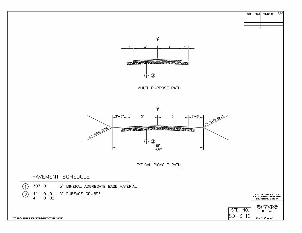

44
7. Appendix
7-1. Technical Specifications 7-2. Outline of Development Regulations
7-3. Pavement Design Nomographs
7-4. Driveway Regulations
7-4.1. Chapter 21, Article III. Driveways 7-4.2. Ordinance No. 2503, State of Franklin Road
7-5. T-DOT Entrance Regulations 7-6. Lighting Regulations 7-7. Erosion and Sedimentation Regulations 7-8. Floodplain / Sinkhole Regulations

7-1. Technical Specifications

7-1,Technical Specifications Page 1 of 3
TECHNICAL SPECIFICATIONS
All roadway construction shall conform to the most recent edition (March 1, 1995) of the Tennessee Department of Transportation Standard Specifications for Road and Bridge Construction and the Standard Roadway and Structure Drawings and as additionally hereinafter supplemented by specifications.
Copies of related Tennessee Department of Transportation documents may be purchased from:
The Construction Division Office State of Tennessee Department of Transportation James K. Polk Bldg. Nashville, TN 37234-0350
DRAWINGS AND SPECIFICATIONS
A. The intent of the DRAWINGS and SPECIFICATIONS is that the CONTRACTOR shall furnish all labor, materials, tools, equipment and transportation necessary for the proper execution of the WORK in accordance with the City of Johnson City Public Works Standards and for all incidental work necessary to complete the PROJECT in an acceptable manner, ready for use, occupancy, or operation by the OWNER.
B. These specifications, and Supplemental Specifications, the Plans, Special Provisions and all other documents
which are part of the Permit, are intended to be complementary and to describe and provide for a complete work. Requirements in one of these are as binding as if occurring in all of them. In case of discrepancy, Supplemental Specifications will govern over these Specifications, PLANS will govern over both, and Special Provisions will govern over both PLANS and SPECIFICATIONS. In interpreting PLANS, calculated dimensions will govern over scaled dimensions; Plans, typical cross-sections, and approved working drawings will govern over standard sheets.
C. In case of conflict between the DRAWINGS and SPECIFICATIONS, the Tennessee Department of
Transportation Standard Specifications for Road and Bridge Construction shall govern. Figure dimensions on DRAWINGS shall govern over general Drawings.
D. Any discrepancies found between the DRAWINGS and SPECIFICATIONS and site conditions or any
inconsistencies or ambiguities in the DRAWINGS or SPECIFICATIONS shall be immediately reported to the ENGINEER, in writing, who shall promptly correct such inconsistencies or ambiguities in writing. WORK done by the CONTRACTOR after discovery of such discrepancies, inconsistencies, or ambiguities shall be done at the CONTRACTOR’S risk.
WORK SEQUENCE
Coordinate the construction schedule and operations with the City’s Representative. Every effort will be made by the CONTRACTOR to meet the specified deadline for completion of work on the total project. Traffic controls will be used to safely maintain the traffic flow through the work zone. No street closings will be scheduled without 10 days prior notice given to the City and receipt of City’s approval. The contractor shall notify the City at least five (5) days in advance of beginning the separate phases of construction.

7-1,Technical Specifications Page 2 of 3
STORM PIPE BACKFILL
Backfill all storm pipe construction within the limits of the roadway (back-of-sidewalk to back-of-sidewalk) with manufactured mineral aggregate backfill material to the top of the trench or as specified otherwise in the plans. Backfill shall be placed as specified in the TDOT Standard Specifications, Section 204.11. All cost of backfill material other than Class “B", bedding as described in the TDOT Standard Specifications under Section 204 shall be included in the price bid for other items or as specified otherwise in the plans and specifications.
COMPACTION
Compaction for subgrade, base, and surface materials, as well as for pipe and structure backfill, shall conform to the TDOT Standard Specifications. The equipment used for compaction of backfill material shall be equipment specifically designed to compact these materials. Equipment not specifically designed for compaction shall not be approved for use. Manufactured mineral aggregate backfill material shall be placed no deeper than 18 inches from the bottom of the trench before vibrating, compacting or tamping to ensure that adequate support material has been placed under the pipe haunches.
CONCRETE FINISHING
All applicable TDOT specifications shall be followed for concrete finishing operations. These specifications are intended to supplement the TDOT Standard Specifications. No water shall be added to the concrete mix after it leaves the plant. Slump Written approval from the Owner’s ENGINEER must be obtained to exceed the specified TDOT maximum slump for the particular structure or pavement in questions. In no case shall approval be given for the slump of concrete to be greater than 5 inches. If approval is given by the ENGINEER to exceed the TDOT maximum slump, no additional water shall be applied to concrete pavement and sidewalk surfaces for the purposes of hastening the finishing process. Screeding or Striking Off Screeding must be completed before there is excess moisture or bleed water on the surface. Bull Floating Bull floating should immediately follow screeding and must be completed before there is excess moisture or bleed water on the surface. Do not seal the surface by bull floating because this may prevent the bleed water from surfacing. Edging Use a wide edger which covers a large area in order to avoid sealing the surface. Waiting After the edging step is completed, all finishing operations shall cease until all water has evaporated or been removed and until the concrete will sustain a maximum 1/4 inch indentation when stood upon. Jointing or Grooving The depth of contraction joints should be at least 1/4 the thickness of the slab. Hand Flouting (Optional) If hand floating is done, it will only be permitted after the waiting period.

7-1,Technical Specifications Page 3 of 3
Brooming In addition to Section 701 of the TDOT Standard Specifications, the broom shall not contain excess water. If the broom is washed during the finishing operation, it shall be shaken thoroughly to remove any excess water before reapplying the broom to the surface. Sawing Joints Joints made with a power saw shall be cut within 4 to 12 hours after the slab has been placed and finished. Joints shall be cut as soon as the concrete surface is firm enough not to be torn or damaged by the blade, and before random shrinkage cracks can form in the slab. Curing in Cold Weather The protection of concrete in cold weather shall be maintained for 120 hours after placing as specified in Section 604 of the TDOT Standard Specifications. At the end of the curing period, let the concrete cool gradually to air temperature to avoid cracking due to thermal shock. Curb and gutter sections shall be protected as specified by TDOT for sidewalks. The method of cold weather protection shall be outlined by the CONTRACTOR in advance to the ENGINEER, and the ENGINEER shall approve the method to be used in writing. The ENGINEER may specify that the protection be above and beyond what is required by TDOT Cold weather protection methods that may be considered for approval include, but are not limited to, the following: a) Insulating blankets designed specifically for protecting concrete slabs and structures. The manufacturer’s specifications shall be submitted to the ENGINEER prior to approval of this method. b) A combination of polyethylene sheeting and straw which is installed by placing a one foot layer of straw between two layers of the sheeting to form a blanket. A prototype section, no longer than 50 feet, shall be placed for the ENGINEER’s review prior to approval of this method. Curing In Hot Weather Protect the concrete against moisture loss at all times during placing and during the curing period.
CONCRETE CURING All curing methods shall conform to Section 501 of the TDOT Standard Specifications. When using the Impervious Membrane Method, the CONTRACTOR shall submit the manufacturer’s application specifications to the ENGINEER prior to initiation of use. CONTINGENCY As indicated in the Bid Form, the Bidder shall subtotal the extended prices of the bid items and then calculate the contingency based on the specified percentage of the subtotal. The Bidder should then add the subtotal and the contingency to obtain the Grand Total. The Grand Total will be used to determine the low bidder. The contingency item will be used to pay for unforeseen work on the project that is necessary to keep the project moving.

7-2. Outline of Development Regulations

OUTLINE OF
DEVELOPMENT REGULATIONS
11.1 GENERAL PROVISIONS
11.2 ADMINISTRATIVE PROCESS FOR DEVELOPMENT – GENERAL
11.2.1 PREDEVELOPMENT MEETING
11.2.2 PREDEVELOPMENT REQUIREMENTS 11.2.2.1 Zoning Variances or Special Exceptions 11.2.2.2 Subdivisions or Resubdivisions 11.2.2.3 Rezonings or Annexations 11.2.2.4 Overlays
11.2.3 REVIEW PROCESS FOR FINAL SITE PLAN APPROVAL 11.2.4 ISSUANCE OF THE BUILDING PERMIT 11.2.5 COMPLIANCE REQUIREMENTS
11.3 SITE PLAN SUBMISSION REQUIREMENTS
11.3.1 GENERAL 11.3.2 MINOR SITE PLAN APPROVAL 11.3.3 MAJOR SITE PLAN APPROVAL
11.4 BUILDING PERMIT APPLICATION 11.5 PERFORMANCE STANDARDS
11.5.1 STORM WATER MANAGEMENT 11.5.2 GRADING 11.5.3 EROSION AND SEDIMENTATION REGULATIONS 11.5.4 SITE ACCESS AND TRAFFIC 11.5.5 SPECIAL USE PERMIT FOR DEVELOPMENT IN A FLOODPLAIN 11.5.6 AQUATIC RESOURCES ALTERATION PERMIT (ARAP) 11.5.7 ARMY CORP/TVA JOINT PERMIT 11.5.8 FEMA FLOOD MAP CHANGE 11.5.9 SINKHOLE PERMIT 11.5.10 ELECTRICAL PERMIT 11.5.11 GAS/MECHANICAL PERMIT 11.5.12 SIGN PERMIT 11.5.13 BULK CONTAINERS (DUMPSTERS) 11.5.14 MISCELLANEOUS
11.6 ADMINISTRATION AND ENFORCEMENT
11.6.1 ADMINISTRATION 11.6.2 DUTIES AND LIMITATIONS OF THE CHIEF BUILDING OFFICIAL 11.6.3 PERMIT COMPLIANCE 11.6.4 FEES 11.6.5 CERTIFICATE OF OCCUPANCY 11.6.6 ENFORCEMENT, VIOLATION AND PENALTY
Section 7-2, Outline of Development Regulations Page 1 of 13

ARTICLE XI
DEVELOPMENT REGULATIONS
11.1 GENERAL PROVISIONS
11.1.1 These regulations are intended to provide information concerning the development and processing of development plans for properties located within the corporate limits. Most developments can be approved by city staff, following guidelines established by the Board of Commissioners and adopted ordinances. In a few instances, such as the city’s planned business and planned residential zones, industrial zones, or through appeals of the staff approval process, the Planning Commission and Board of Commissioners may exercise final site plan approval authority.
11.1.2 Several pages of zoning summaries are located at the end of Article VI. These summaries provide basic zoning information concerning the uses allowed in individual zoning classifications and setback requirements. The Planning Department also has a zoning map available to indicate the geographic extent of individual zones, as well as more detailed, larger-scale mapping.
11.1.3 Approval of a final site plan and building permit is required prior to initiation of any developmental activity within the City of Johnson City. Developments covered by these regulations include any man-made change to improved or unimproved property including but not limited to, grading, excavation, filling, paving, tree removal under certain conditions, and the addition or alteration of structures. For most development questions, the primary contact for a developer is the office of the Development Coordinator within the Planning Department. The primary functions of that office are subdivision, zoning and final site plan approval processes, but it also serves as a link to city departments involved with development.
11.1.4 Administrative processing or permit fees are charged for many of the processes listed in this Article, and these fees are generally not addressed here. The office of the Development Coordinator can advise the developer regarding such fees.
11.2 ADMINISTRATIVE PROCESS FOR DEVELOPMENT – GENERAL
11.2.1 PREDEVELOPMENT MEETING: A predevelopment meeting with the Development Coordinator and other appropriate city departments is encouraged to become familiar with the various regulations and processes. Developers of larger developments are especially encouraged to do so.
11.2.2 PRE-PROCESSING REQUIREMENTS: Certain preparatory zoning or subdivision requirements may be necessary prior to development of a final site plan. A review of the particular zoning requirements of the property to be developed, located in Article VI, will enable the developer to determine whether the property can meet the requirements for development. Pre-processing steps may include the subdivision or resubdivision of land, setback variances, rezonings, or special Exceptions that require special processing. Neither these reviews, nor the generalized or conceptual site reviews sometimes required as a prerequisite for rezonings, variances, or special exceptions, constitute final site plan approval, although conditions from these reviews may be attached to any submitted final site plan. The Development Coordinator’s office can assist with these requirements or processing questions. 11.2.2.1 ZONING VARIANCES OR SPECIAL EXCEPTIONS
A. Developments needing a variance to zoning requirements or those developments that require Special Exception approval for their specific use shall be required to submit to the Board of Zoning Appeals for consideration.
B. The Board of Zoning Appeals may require a lesser amount of site plan documentation than that contained in the final site plan approval procedures of Article XI. Documentation required for special exceptions may be described in the specific zoning category of the property in Article VI.
C. Submission of items for the Board’s Agenda must be done according to its rules of procedure contained in Article XII. The Planning Department processes its agenda.
11.2.2.2 SUBDIVISIONS OR RESUBDIVISIONS A. Jurisdictional authority for all subdivisions lies with the Johnson City Regional
Planning Commission. Submission of items for the Commission’s agenda is regulated by its rules in the Appendix to this Code.
B. Properties needing subdivision or resubdivision prior to final site plan approval and development should contact the Development Coordinator’s office for submission requirements. Copies of the Commission’s Subdivision Regulations are available from the Planning Department at a nominal cost.
C. Under some circumstances, such as B-4, a subdivision cannot be approved without an approved, generalized site plan. Procedures contained within the specific zoning category for the development will indicate whether such pre-approval processing is required.
D. Multiple building developments are required to received subdivision approval in accordance with the Subdivision Regulations, regardless of whether they are
Section 7-2, Outline of Development Regulations Page 2 of 13

rental or condominium developments. Such approval is in addition to the approval processes located in this Article.
11.2.2.3 REZONINGS OR ANNEXATIONS
A. Jurisdictional authority lies with the Johnson City Regional Planning Commission and the Board of Commissioners.
B. Owners/developers of property needing either rezoning or annexation prior to final site plan approval and development may, at their request, apply for final site plan approval conditional upon such rezoning or annexation.
C. Developers of properties requiring either rezoning or annexation must contact the Planning Department to make application. Rules for applying for rezonings are contained in the Appendix to the Zoning Code, under Planning Commission established procedures.
11.2.2.4 OVERLAYS:
In addition to the specific zoning district in which a property is located, other zoning restrictions in the form of overlays may be applicable, and any prospective developer should be aware of them.
A. HCO, HVO, and CCO – Includes Sections 6.28 to 6.30 in the Zoning Code and
their locations are shown on the zoning map. These overlays contain special appearance standards for utilities, buildings, and signage along certain scenic corridors.
B. Flood Regulations – These are applicable if the property to be developed contains a floodplain or sinkhole. These regulations are contained in Article VIII.
C. Curb-cut ordinance – This regulation is not included in this Code, but affected properties are located along State of Franklin Road. Ordinance #2503 is available from the City Recorder’s or Planning Offices.
D. Landscape Plan – Review of a landscape plan may be required prior to making application for final site plan approval. Sections 5.5.1.3 and 5.5.6 contain the regulations to determine if such a preparatory submission is necessary.
11.2.3 REVIEW PROCESS FOR FINAL SITE PLAN APPROVAL 11.2.3.1 Upon satisfactory completion of any prerequisite zoning or subdivision processes,
the developer may prepare a final site plan for review. In some instances, a final site plan may be submitted concurrent with a Building permit application (see 11.4) or while a zoning or subdivision process is pending. The Development Coordinator can advise in this regard.
11.2.3.2 Detailed site plan submission requirements are found in Section 11.3. The City has an established review procedure to promptly process many final site plans at the staff level. Those final site plans to be reviewed by its governing bodies take longer to process. Deficiencies in submitted plans may also delay the processing schedule, regardless of the method of review. The review process is summarized below by zoning district:
STAFF REVIEW COMMISSION REVIEW R-1 to R-6 RP R0-1 TM MS-1 Appeals of B-4, B-5, HC, BP, RTP, MX* B-1 to B-3 I-1 and I-2 after June, 1989** B-4 to B-5* PB I-1 and I-2 prior to June, 1989** HC* BP* RTP* MX*
*Final site plans are normally reviewed by staff. Failure to reach agreement between the developer and city staff concerning final site plan conditions shall necessitate commission review. **Processing is dependent upon the date the property became zoned for industrial use. Failure to reach agreement on staff-reviewed final site plans shall necessitate commission review. 11.2.3.3 Five (5) complete sets of the final site plan must be submitted to the Development
Coordinator’s office for staff reviewed plans, except for single-family and two family, which require one (1) set of plans. The departments or divisions of Planning, Engineering, Water and Sewer and any others as appropriate then review staff-reviewed final site plans. Each promptly reviews the site plan for conformity with City standards and conveys their findings to the Development Coordinator. If any deficiency is found in the plan, the applicant may agree to correct them and resubmit an equal number of corrected site plans to the Development Coordinator for review, or the applicant may appeal if such appeal is authorized in Section 11.2.3.2. Developers with corrected final site plans found by the development Coordinator to comply with all requirements may then apply for the appropriate grading or building permits.
Section 7-2, Outline of Development Regulations Page 3 of 13
11.2.3.4 Staff-reviewed final site plans that are appealed by the developer for commission review are to be processed as follows: A. Five (5) additional sets of the final site plan must be submitted. B. If the applicant disagrees with the findings of the city staff, he may elect to
appeal those findings to the Planning commission and Board of Commissioners. Such appeal should be made in writing to the Development Coordinator and shall state the reasons why the applicant fees the final site plan is in compliance. The appeal shall be filed no later than seven (7) full working days prior to the next Planning Commission meeting.
C. The Planning Commission shall review the disputed final site plan and hear evidence from the applicant, the staff, and from any other interested persons. After hearing evidence, the Planning commission shall recommend to the Board of Commissioners that the final site plan be approved as submitted, approved with amendments, or disapproved. In determining its recommendation, the Planning Commission shall recommend to the Board of Commissioners that the final site plan be approved as submitted, approved with amendments, or disapproved. In determining its recommendation, the Planning Commission shall take into consideration the character of the surrounding area so as to protect adjoining residentially zoned lots and residential uses, to provide for the public safety, and to prevent traffic congestion.
D. Before recommending approval, the Planning Commission may make reasonable additional requirements concerning, but not limited to, the limitation of uses; landscaping, lighting, screening or planting; setback and height of buildings; paving and location of curb cuts, drives, and parking areas; drainage and the location of access ways.
E. After receiving the recommendation of the Planning Commission, the Board of Commissioners shall review the final site plan and the evidence presented by the staff, the applicant, and any other concerned persons. After such review, the Board of Commissioners shall approve, disapprove, or approve with amendment the final site plan. In determining its action, the Board may also make reasonable additional requirements.
11.2.3.5 Final site plans with mandatory commission review shall be submitted in
accordance with Planning Commission procedures contained in the Appendix to the Zoning Code. The review procedure for the Board of Commissioners may be obtained from the Development Coordinator’s office. Ten (10) copies of the final site plan must be submitted. A. The Development Coordinator’s Office performs an advance review of the
final site plan and provides an advance list of deficiencies, if any, to the developer in an effort to allow corrections to be made prior to Commission review. Ten (10) copies of the full, final site plan must accompany any such resubmission.
B. After hearing evidence, the Planning Commission shall recommend to the Board of Commissioners that the final site plan be approved as submitted, approved with amendments, or disapproved. In determining its recommendation, the Planning Commission shall take into consideration the character of the surrounding area so as to protect adjoining residentially zoned lots and residential uses, to provide for the public safety, and to prevent traffic congestion.
C. Before recommending approval, the Planning Commission may make reasonable additional requirements concerning, but not limited to, the limitation of uses; landscaping, lighting, screening or planting; setback and height of building; paving and location of curb cuts, drives, and parking areas; drainage and the location of access ways.
D. After receiving the recommendation of the Planning Commission, the Board of Commissioners shall review the final site plan and the evidence presented by the staff, the applicant, and any other concerned persons. After such review, the Board of Commissioners shall approve, disapprove, or approve with amendment the final site plan. In determining its action, the Board may also make reasonable additional requirements.
11.2.3.6 Final site plan approval remains in effect for a period of (1) year from the date of
approval or conditional approval, unless development has commenced before the expiration of approval and continues diligently, as determined by the Chief Building Official. Failure to perform any substantive work over a period of one (1) year shall result in the lapse of final site plan approval. Any reapplication for approval shall be treated as a new application, subject to current rules and regulations. Nothing in this regulation shall prevent the phased development of any tract or tracts, provided site work continues diligently, as determined by the Chief Building Official.
11.2.4 ISSUANCE OF THE BUILDING PERMIT:
11.2.4.1 Final site plan approval does not constitute approval of building construction plans or approval for a building permit. The permitting process is separate and requires
Section 7-2, Outline of Development Regulations Page 4 of 13

the resubmission of the approved final site plan in addition to building construction plans.
11.2.4.2 A building permit is required when construction or demolition is planned on private property in the city. The City Code states that “a person, firm or corporation shall not erect, construct, enlarge, alter, repair, move, improve, remove, convert or demolish any sign, building or structure, nor shall any person, firm, or corporation install, enlarge, alter, repair, move, improve, remove, convert or replace any gas system, plumbing system, electrical system or mechanical system of a building or structure, or cause the same to be done, without first obtaining a permit for such project from the Chief Building Official.” Two (2) complete sets of plans are to be submitted to the office of the Chief Building Official, Building Division, Municipal and Safety Building, 601 East Main Street. The mailing address is P.O. Box 2150, Johnson City TN 37605.
11.2.4.3 Development shall not commence until the appropriate permit or permits have been issued.
11.2.4.4 Construction must begin within six (6) months from the date of issuance of any permit and be diligently pursued to avoid expiration of the permit.
11.2.4.5 Permits are normally obtained after all final site plan and building plan approvals are accomplished. Grading permits, however, may be issued in advance if stormwater and sedimentation/erosion control plans have been reviewed and approved. Any permits that may be issued prior to full final site plan and building plan approval are the responsibility of the developer and shall not be construed as the City having approved the full site and building plans.
11.2.4.6 Electrical, plumbing and mechanical/gas permits are to be obtained by the certified and licensed professionals who will perform the work. The only exception is when a residential homeowner takes and passes the applicable test or tests administered by the Chief Building Official. Electrical, plumbing, and mechanical/gas permits are obtained separately from any building or grading permits.
11.2.5 COMPLIANCE REQUIREMENTS
11.2.5.1 All construction must conform to approved plans. Certain inspections, construction measures and other compliance factors must also be met during construction. A comprehensive list will be supplied when the building permit is obtained. Most inspections require a 1 day notice. Utility inspections are generally required prior to utilities being covered, when rough installation is achieved, and upon final installation. Building structural inspections are required of the foundation, framing, foundation drain/dampproofing of foundation walls, insulation, and final. All inspections must be completed and approved prior to obtaining a certificate of occupancy. Failure to observe required inspection schedules may result in the issuance of a “stop work order” and/or penalties.
11.2.5.2 It is the responsibility of the developer to assure that the streets and sidewalks surrounding the site are kept clear of mud and debris during construction.
11.2.5.3 Proper and sufficient erosion and sedimentation control measures must be used and maintained, and erosion, sediment and debris must be contained on the development site, in accordance with the Johnson City Public Works Department standards of latest issue.
11.2.5.4 Burning must conform to the requirements of the Fire Division’s Burn Policy, available from the Building Division. Disposal of all construction materials must conform to local, state and federal requirements.
11.2.5.5 The developer shall be responsible for the design and construction of all on-site public facilities that are necessary to provide safe and/or efficient access or services to a development. Except for sidewalks, which are regulated by Article IX of the Zoning Code and Chapter 21 of the City Code, the character of the improvement shall control in determining whether an improvement is considered on-site or off-site, and the actual location of the improvement shall not be determinative. Thus, left or right turn lanes, traffic signals, acceleration/deceleration lanes, utilities, etc., may be considered as on-site even when not located on the development premises, if such facilities are necessary to serve specific development. Conversely, off-site improvements are public facilities designed to provide services to the general public.
11.3 FINAL SITE PLAN SUBMISSION REQUIREMENTS 11.3.1 GENERAL
11.3.1.1 Except for grading, demolition or interior renovation, approval of a final site plan is required prior to application for a building permit. Final site plan submission requirements are divided into either minor or major categories, with the difference being the level of information required.
11.3.1.2 Since many of the major utility and drainage concerns for single family and two family residential units have already been addressed in the subdivision process, a minor final site plan submission is allowed in accordance with the requirements of Section 11.3.2. The Chief Building Official may require the submission of additional information if, in his opinion, the situation warrants such submission.
11.3.2 MINOR FINAL SITE PLAN APPROVAL (Single and two family residential or related accessory structures, having access from an existing public street).
Section 7-2, Outline of Development Regulations Page 5 of 13

11.3.2.1 Submission of one (1) set of plans is required for all new construction, reconstruction or expansion. Single and two family minor final site plans may be submitted concurrent with the application for building permit approval in 11.4.
11.3.2.2 A generalized final site plan, drawn to scale, is required. Acceptable scales for the drawing are 1”=10’, 1”=20’, 1”=30’, 1”=40’ and 1”=50’. The minimum drawing size shall be on 8 ½” X 11” paper. Included on the final site plan shall be the location and height of all existing and proposed structures, drives, property lines, building setback lines, easements, adjacent street rights-of-way, utility lines, topographic features such as streams, floodways, flood plains, sinkholes, and directions of existing and proposed drainage.
11.3.3 MAJOR FINAL SITE PLAN APPROVAL 11.3.3.1 Submission of two (2) sets of plans is required for developments that will be staff
reviewed. Those to be commission reviewed must submit ten (10) complete sets of the final site plan. Major final site plans to be staff-reviewed may be submitted concurrent with the application for building permit approval in 11.4.
11.3.3.2 A generalized final site plan, drawn to scale, is required. Normal submission size is 24 inches by 36 inches, but smaller developments may submit copy sizes as small as 18 inches by 24 inches. Normal scales for the drawing are 1”=10’, 1”=20’, 1”=30’, 1”=40’, and 1”=50’. Larger developments may need to be drawn at 1”=100’ or 1”=200’ scales, but no scale smaller than 1”=200’ shall be used. If more than one sheet is necessary for the final site plan, an index sheet shall be included. The final site plan shall include: A. The location, height, and dimensions of all existing and proposed structures,
drives, parking spaces, property lines, building setback lines, easements, adjacent street rights-of-way, walkways, utility lines, topographic features such as streams, floodways, flood plains and sinkholes, and directions of existing and proposed drainage.
B. The relation of the project to the adjoining street system and surrounding area, including the zoning and land use of surrounding properties;
C. The proposed use of the land and buildings; D. The location and extent of existing and proposed landscaping and buffer yards
in accordance with Article V Section 5.5; E. The location and extent of existing and proposed sidewalks, in accordance
with Article IX; F. The complete grading, drainage, and sedimentation and erosion control plans,
including all existing and proposed drainage and erosion control facilities, in accordance with the Johnson City Erosion and Sedimentation Regulations, and the Stormwater Regulations, of latest issue;
G. Storm water runoff calculations and detention/retention facility plans; H. For developments utilizing flood plains or sinkholes for all or a portion of
their drainage (either on-site or off-site), plans in accordance with Article VIII.
I. Profiles of proposed sanitary sewers and storm water sewers with grades, sizes, and elevations indicated, and similar details of adjacent existing facilities that will be interconnected, in accordance with the Water and Sewer Department “Standards of Design for Water and Sewer Lines”;
J. Proposed water distribution system showing pipe sizes and the location of all pumps, valves, and fire hydrants and similar details of adjacent, existing facilities that will be interconnected, in accordance with the Water and Sewer Department “Standards of Design for Water and Sewer Lines”;
K. The location and extent of other utility facilities, including, but not limited to, electric, telephone and TV cable lines, natural gas lines, and poles for power, telephone or other utility lines;
L. An exterior lighting plan as specified in Article V Section 5.6; M. Copies of any state or federal permits for which application has been made or
approved; N. The location, extent, and screening techniques to be utilized for any recycling,
trash, or dumpster facilities, in accordance with the Public Works Department standards for Bulk Containers, available from the Building Division.
O. The location and size of proposed freestanding and wall signage, if known (See 11.5.13);
P. A traffic impact study when required, completed and submitted as a separate report as outlined in Section 4 of the Johnson City Public Works Department Standards, of latest issue. Section 11.5.4.4.H of this outline and Section 4-1.1 of the Johnson City Public Works Department Standards, of latest issue establish the criteria for requiring the submittal of a traffic impact study.
11.4 BUILDING PERMIT APPLICATION 11.4.1 For single-family and two-family dwellings, the following structural drawings must be
submitted: One (1) set of structural drawings drawn to scale, for all buildings is required. This must include a foundation plan, floor plan, a heating and cooling layout plan, electrical and plumbing layout, natural gas connections (if any) and layout, typical cross-section of the exterior wall, foundation and roof assembly details, and one (1) set of the approved final site plan. If the final site plan has not been approved and is being submitted concurrent with the building permit application, one (1) set of the final site plan shall be submitted.
Section 7-2, Outline of Development Regulations Page 6 of 13

11.4.2 For all other uses, the following structural details shall be submitted: Two (2) sets of structural drawings, drawn to scale, for all buildings are required. These must include a foundation plan, floor plan, a heating and cooling layout plan, electrical and plumbing layout, natural gas connections (if any) and layout, typical cross-section of the exterior wall, foundation and roof assembly details, and two (2) sets of the approved final site plan. If the final site plan has not been approved and is being submitted concurrent with the building permit application, five (5) sets of the final site plan shall be submitted.
11.4.3 Unless corrections to the plans are necessary, the review process for building permits normally requires three (3) working days for single-family and two-family plans, and five (5) working days for all other plans.
11.5 PERFORMANCE STANDARDS (TO BE CONSIDERED IN BOTH THE DESIGN AND CONSTRUCTION STAGES)
11.5.1 STORM WATER MANAGEMENT 11.5.1.1 Higher ground has an implied easement to drain to and across lower ground, but
the lower ground is not obligated to receive surface water in different quantities or at different times than would flow naturally before development of the higher ground occurred.
11.5.1.2 A registered engineer must analyze storm water flow from developments. If surface water runoff is found to be exiting the development in different quantities and at different times, then methods of buffering or abating the surface water shall be included in the design.
11.5.1.3 The developer’s engineer must submit drainage calculations along with the final site plan.
11.5.1.4 The City regulates the location and extent of development within and/or adjacent to floodplains or sinkholes. Article VIII (Flood Regulations) provides specific instructions for affected properties.
11.5.1.5 The Johnson City Public Works Department Standards, of latest issue provides more information on Storm Water Management.
11.5.2 GRADING 11.5.2.1 Adjoining Property Rights: Adjoining property has the right to expect lateral
support from neighboring property, and the right to continue to receive reasonable light exposure and air circulation. To insure the continuation of these rights, a slope setback in conjunction with a maximum slope is established.
11.5.2.2 Slope Setback: The top of any cut slope and the bottom of any fill slope shall set back from the property line a distance equal to the height of the slope. The land surface within this setback area shall be left in a natural condition. The steepest allowable slope shall be 3 feet of run to 1 foot of rise.
11.5.2.3 Retaining Wall: When it is necessary to place permanent structures closer to adjoining property than the slope setback and 3 to 1 slope combination will allow, a retaining wall with a safety fence along its top edge may be used. However, no portion of the wall may encroach onto the required slope setback area specified in 11.5.2.2, above.
11.5.3 EROSION AND SEDIMENTATION REGULATION 11.5.3.1 No footing inspection will be approved until proper erosion control is installed.
Minimum erosion control measures shall consist of straw bales and silt fencing. 11.5.3.2 Erosion, sedimentation, and stormwater must be controlled in accordance with
the Johnson City Erosion and Sedimentation, and Stormwater Control regulations. Reseeding or sodding any cleared or graded site shall be required where no building activity has occurred within a thirty- (30) day period.
11.5.3.3 Erosion from the building site shall not encroach onto adjacent properties. In the event that erosion material should encroach onto adjacent property, the owner and/or developer will be responsible for the clean up, damage, and/or restoration.
11.5.3.4 Erosion control barriers must be used to contain mud and silt. The location of these barriers must be shown on the final site plan on a separate erosion control plan.
11.5.3.5 Erosion control barriers must be maintained on a regular basis and kept intact and effective.
11.5.3.6 Each developer is responsible for keeping the public street or alley clear of mud, debris, and building materials. The owner and/or developer is responsible for removing any building site material from the public right-of way. If the owner and/or developer fails to clear the street or alley, the Chief Building Official may ask city crews to clear the street or alley and then charge the cost of such work to the owner and/or developer. Failure to reimburse the city for such costs shall be cause for withholding a certificate of occupancy and/or civil damages.
11.5.4 SITE ACCESS AND TRAFFIC 11.5.4.1 GENERAL
A. A driveway permit is required each time a private access is proposed to connect to a public street. A separate submission for a driveway connecting to a city street is not necessary when a driveway is an integral part of an overall construction project and approved in the final site plan process, since the driveway permit review and approval is conducted simultaneously with final site plan approval.
B. City regulations for driveway construction are also located in Chapter 21, Article III of the Johnson City Code; and the Johnson City Public Works
Section 7-2, Outline of Development Regulations Page 7 of 13

Department Standards, of latest issue. Tennessee Department of Transportation regulations shall apply to driveway construction along state highway routes.
C. To promote and protect the safety and function of city streets, the internal circulation and the location and number of curb cuts shall be carefully regulated. The City Engineer shall use projected and actual traffic counts, surrounding land use, street design and capacity, and established engineering design guidelines as the basis for his determinations.
11.5.4.2 CITY APPROVED DRIVEWAY CONNECTIONS A. All driveway connections to the public streets and highways must receive a
separate permit from the Building Division. The Engineering Division of the Public Works Department will conduct inspections during construction.
B. Applications for a driveway permit are filed at the Building Division Office, located in City Hall. The Engineer and/or designate of the City Engineer will review the information provided by the applicant and either issue approval or request more information prior to issuance of approval. The applicant will submit any additional information to the Building Division Office for additional review by the City Engineer, or City Engineer designate.
C. The type of drawing needed for review of the application must contain information “…showing the type of construction, the length of the driveway, the exact location of the driveway, and any other information which may be required by the City Engineer.”
D. Before cutting any curb for a driveway, call the City Engineer’s office for a curb inspection, and then call again for a final inspection when the driveway construction is complete.
11.5.4.3 STATE-APPROVED DRIVEWAY CONNECTIONS A. The Tennessee Department of Transportation (T-DOT) issues driveway
connection permits along state routes. When a T-DOT permit is required, the regular City permit process will be replaced by the T-DOT permit process, and the applicant will be required to make only one application simultaneously with T-DOT and the City. These drawings must be reviewed and approved by the City Engineer prior to submittal to T-DOT.
B. Forms for the T-DOT permit are available at the Building Division office, located in the Municipal and Safety Building. Instructions on how to file this permit are attached to the T-DOT form.
C. The joint City / T-DOT permit process is initiated by picking up a permit form at the Building Division office and submitting a preliminary final site plan for review by the City Engineer and the T-DOT Traffic Engineer. The T-DOT application packet includes instructions for filing for their permit. If you have any questions about the process, you may contact the City Engineer’s office or the T-DOT Traffic Engineer’s office.
D. Submit five (5) copies of the final site plan to the City Engineer for review. After approval by the City Engineer, you will mail all five (5) copies of the final site plan to the Knoxville office of the T-DOT Traffic Engineer for their review. When they have approved the proposal they will send you an approved copy of the final site plan. You will be free to begin work upon receiving approval.
11.5.4.4 TRAFFIC A. Traffic Impact Study: To adequately assess the impact of any development
or redevelopment proposal on the existing and planned transportation system, a traffic impact study will be required, given any of the following conditions: 1. Adjacent Roadway ADT: A traffic impact study shall be required for
any development proposal for new development or redevelopment of an existing site that is proposed adjacent to a roadway with an existing or 20 year projected Average Daily Traffic (ADT) of 3000 vehicles per day.
2. Minimum Peak Hour Volume: A traffic impact study shall be required if any development proposal for new development or redevelopment of an existing site will generate 100 or more added peak-direction trips to or from the site during the adjacent roadway’s peak hours or the development’s peak hour,
3. Previous Traffic Studies: Any development proposal for new development or redevelopment of an existing site with a previous traffic impact study that is more than 1 year old will require an updated traffic impact study.
B. Public Street Widening: If the 20-year traffic projection requires eventual widening of the existing street, then the widening shall be planned for in the design of the development by not locating any of the development within the area needed for the widening of the existing street.
C. Deceleration Lanes: For arterial, major collector and minor collector streets, deceleration lanes shall be constructed adjacent to all entrances at developer expense for developments of both residential and non-residential uses that generate in excess of 300 trips per day.
Section 7-2, Outline of Development Regulations Page 8 of 13

D. Other Additional Lanes: For arterial, major collector, minor collector and other minor streets with existing or 20 year projected traffic volumes in excess of 3,000 ADT; additional turn lanes on the public street may be required for the access points or nearby intersections at developer expense.
E. Additional Lanes for the Driveway: Developments expected to generate significant levels of traffic may be required to provide dual exit lanes for turns in either direction onto the adjacent street and/or frontage road.
F. New frontage roads and associated turn lanes, signalization, etc., shall be the responsibility of the developer and be constructed to public street standards.
G. The site plan shall indicate the location of all existing and proposed traffic control devices.
H. Improvements in sight distances or horizontal/vertical alignments will be required at developer expense when proposed development connections with a street would otherwise have inadequate sight distance. The Johnson City Public Works Department Standards, of latest issue specifies the minimum sight distance criteria.
11.5.5 SPECIAL USE PERMIT FOR DEVELOPMENT IN A FLOOD PLAIN 11.5.5.1 The City of Johnson City participates in the National Flood Insurance
program as administered by the Federal Emergency Management Agency (FEMA). To participate, the City has adopted flood regulations as specified by FEMA, and must enforce the regulations accordingly.
11.5.5.2 The Flood Regulations for the City of Johnson City establish the Chief Building Official as the enforcement officer. The Chief Building Official as the enforcement officer is required to review all construction that is proposed within the designated floodplain and to decide when to issue approval for requests to conduct this work.
11.5.5.3 The City Engineer’s office will assist the Chief Building Official in reviewing applications.
11.5.5.4 The documentation that is required for a special use permit is the same as described for submittal for a commercial building permit. If there is a proposed change in the established floodway, then a more elaborate drainage study is required.
11.5.5.5 If the proposed work in the floodplain is in conjunction with a request for a building permit, then the special use permit is simultaneous with the issuance of the building permit.
11.5.6 AQUATIC RESOURCES ALTERATION PERMIT (ARAP) 11.5.6.1 The purpose of this permit is to allow the developer to alter the course of a
waterway that crosses a development or to move a protected wetland area. 11.5.6.2 The Tennessee Department of Environment and Conservation and the
Environmental Protection Agency issue this permit. 11.5.6.3 The developer must provide evidence of this permit, as a portion of the
documentation, when requesting a building or grading permit. 11.5.7 ARMY CORP/TVA JOINT PERMIT
11.5.7.1 The joint permit is utilized if a developer desires or is required to install a bridge across a stream or river to serve the development.
11.5.7.2 This permit is issued as a joint permit between the TVA and the Army Corp of Engineers. TVA or the Corp of Engineers may deem it unnecessary to issue a permit due to the size or magnitude of flow within the stream.
11.5.7.3 The developer must provide evidence of the permit or its lack of need prior to the issuance of a building or grading permit.
11.5.8 FEMA FLOOD MAP CHANGE 11.5.8.1 A development that will create a change in the floodplain or floodway
must submit documentation to FEMA detailing the changes, and the action to be taken on-site and both up and downstream from the development to facilitate the changes.
11.5.8.2 If FEMA agrees to the submitted changes, a FEMA Flood Map Change will be issued detailing the changes to a previously studied stream.
11.5.9 SINKHOLE PERMIT 11.5.9.1 Sinkholes are regulated according to Article VIII, Flood Regulations. 11.5.9.2 A sinkhole closure permit is required if a developer desires to fill-in a
sinkhole. The Tennessee Department of Environment and Conservation Ground Water Control Division issues the permit. The permit request is to be submitted with drawings prepared by an engineer registered within the State of Tennessee. This permit is normally issued for developments of four (4) acres or larger. However, the permit can be required for smaller sites if, in the opinion of the City Engineer’s Office, the closure of a sinkhole would be detrimental to the development of surrounding properties.
11.5.10 ELECTRICAL PERMIT 11.5.10.1 A separate permit is required for electrical wiring and equipment when
planned in the construction of a structure or structure modification.
Section 7-2, Outline of Development Regulations Page 9 of 13

11.5.10.2 The permit is issued exclusively to certified, licensed electricians. The only exception is when homeowners wish to do the work themselves on their residence, and then the homeowner must take and pass a homeowner’s examination prior to issuance of the permit to them. The Chief Building Official is responsible for the exam.
11.5.10.3 The fee for the permit is based upon the type and amount of work proposed. For more specific information on the amount of the fee, contact the Building Division.
11.5.11 PLUMBING PERMIT 11.5.11.1 A separate permit is required for plumbing work and equipment when
planned in the construction of a structure or structure modification. 11.5.11.2 The permit is issued exclusively to certified, licensed plumbers. The
only exception is when homeowners wish to do the work themselves on their residence, then the homeowner must take and pass a homeowner’s examination prior to issuance of the permit to them.
11.5.11.3 The fee for the permit is based upon the type and amount of work proposed. For more specific information on the amount of the fee, contact the Building Division.
11.5.12 GAS/MECHANICAL PERMIT 11.5.12.1 A separate permit is required for the natural gas, heating and air
conditioning work when planned in the construction of a structure or structure modification.
11.5.12.2 The permit is issued exclusively to certified, licensed mechanical contractors. No natural gas work can be performed in the City of Johnson City except by certified, licensed gas installers.
11.5.12.3 The fee for the permit is based upon the type and amount of work proposed. For more specific information of the amount of the fee, contact the Building Division.
11.5.13 SIGN PERMIT 11.5.13.1 Approval of a final site plan does not constitute approval of any
freestanding or wall signage, unless such signage is approved on the final site plan. No signs, banners, flags or pennants are to be erected without first obtaining a sign permit.
11.5.13.2 When a sign, as permitted under Article VII, is to be erected or constructed a dimensioned sketch of its proposed location on the property shall be shown, and a dimensioned drawing of the sign itself shall be submitted. Failure to submit such details and receive approval in the final site plan review process shall necessitate a separate submission at a later date.
11.5.13.3 Any externally lighted sign shall conform to the Lighting Regulations of Article V Section 5.6.
11.5.14 BULK CONTAINERS (DUMPSTERS) 11.5.14.1 The location and appearance of bulk containers are regulated within the
city. If bulk containers are to be used, they must be shown on the final site plan application. Failure to submit details of the location, size, screening, pad construction and vertical clearance of such locations shall be considered as lacking approval. A supplementary application would then be necessary.
11.5.14.2 The Building Division has available a copy of the City policy for bulk containers which regulates the accessibility, pavement thickness, vertical clearance, screening, dimensions, gates, and pad size and construction.
11.5.15 MISCELLANEOUS 11.5.15.1 Structural drawings for commercial plans must be stamped if the
structure is 5,000 square feet or larger. 11.5.15.2 The contractor must be licensed in the State of Tennessee if the job
exceeds $25,000. A copy of the current state license must be on file with the Building Division.
11.5.15.3 The contractor must also have a current business license, proof of workman’s compensation insurance, and a $10,000 bond with the City of Johnson City.
11.5.15.4 Water and sewer tap fees must be paid prior to issuance of the building permit.
11.5.15.5 Subcontractors (electrical, plumbing, heating, and air) must be licensed and pick up their own permits.
11.5.15.6 Driveway and temporary electrical permits will be issued when the building permit is issued.
11.6 ADMINISTRATION AND ENFORCEMENT 11.6.1 Administration: the Chief Building Official shall administer the Code. 11.6.2 Duties and limitations of the Chief Building Official
11.6.2.1 The Chief Building Official shall have the power to inspect, or cause to be inspected, buildings or premises necessary to carry out the duties of the office in the enforcement of this Code; to issue, or cause to be issued, orders for the approval, repair or improvement of any construction, development, installation, equipment or appliances not in conformity with the requirements of this Code; to issue or cause to be
Section 7-2, Outline of Development Regulations Page 10 of 13

issued stop-work orders for development not in conformity with this Code, or to seek legal relief for non-compliance.
11.6.2.2 It shall be unlawful for the Chief Building Official to approve any plans or issue a permit for any filling and leveling, excavating or construction until he has inspected such plans in detail and found them in conformity with this Code. To this end, the Chief Building Official shall require that every application for a permit for filling and leveling, excavation, construction, moving, alteration, or change in the type of use or type occupancy, shall be accompanied by written statements and plans or plats drawn to scale in sufficient detail to enable him to ascertain whether the proposed work or use is in conformity with this Code.
11.6.2.3 If the proposed development conforms to this and all applicable City codes, and the approved final site plan, the Chief Building Official shall issue the appropriate permits. If any application for such permit is not approved, the reason for disapproval shall be stated in writing on an appropriate denial form.
11.6.2.4 No building or other permit, or license shall be issued until after approval of a final site plan, or any portion for which a permit or license is sought.
11.6.2.5 Before a certificate of occupancy may be obtained, as required by Section 11.5, all site improvements shown on the final site plan shall have been completed and approved by the Chief Building Official.
11.6.2.6 Should it be desirable to occupy a portion of the site before completion of all site improvements, a certified check or performance bond, issued and secured by a reliable, legally authorized and established bonding firm, acceptable to the Chief Building Official, shall be obtained from the developer. Furthermore, an agreement must be entered into between the developer and the city authorizing the use of proceeds from said bond or check to complete the required improvements in the event the developer fails to comply with these regulations within 12 months from the date of agreement.
11.6.2.7 The Chief Building Official may accept a preliminary application and a lesser number of submitted documents than those listed above in situations where a basic clarification is desired ahead of proceeding with further technical work. The Chief Building Official may on such preliminary submittal take the formal action of denial and referral to the Board of Appeals; provided, however, that a zoning compliance permit may not be issued until all information required in Subsection 11.6.2.2 is filed and approved.
11.6.2.8 The Chief Building Official is under no circumstances permitted to grant exceptions to the actual meaning of any clause, order, or regulation contained in this Code to any person making application to excavate, construct, move, alter, or use either buildings, structures or land; nor is the Chief Building Official permitted to make changes to the Code or to vary the terms of this Code in carrying out his duties.
11.6.2.9 The duties and responsibilities of the Chief Building Official for Article VIII, Flood Regulations, shall include, but not be limited to , the following: A. Review of all development permits to assure that the requirements
of the Flood Regulations have been satisfied, and that proposed building sites will be reasonably safe from flooding;
B. Notify permittee that additional federal or state permits may be required, and if specific federal or state permit requirements are known, require that copies of such permits be provided and maintained on file with the development permit. This shall include Section 404 of the Federal Water Pollution Control Act Amendments of 1972, 33 U.S.C. 1334. Copies of the joint Army Corp. and TVA permits and Tennessee Department of Environment and Conservation Aquatic Resources Alteration Permit (ARAP) are included in the Floodplain Development Permit Guide;
C. Notification to adjacent communities and the Tennessee Department of Economic and Community Development, Local Planning Office, prior to any alteration or relocation of a water course, and submission of evidence of such notification to the FEMA and the Tennessee Department of Environment and Conservation;
D. Record the actual elevation (in relation to mean sea level or highest adjacent grade, whichever is applicable) of the lowest floor (including basement) of all new or substantially improved buildings, in accordance with Section 8.3.1.2;
E. Record the actual elevation (in relation to mean sea level or highest adjacent grade, whichever is applicable) to which the new or substantially improved buildings have been flood-proofed, in accordance with Section 8.3.1.2;
Section 7-2, Outline of Development Regulations Page 11 of 13

F. When flood proofing is utilized, the Chief Building Official shall obtain certification from a registered professional engineer or architect, in accordance with Section 8.3.1.2;
G. Where interpretation is needed regarding the exact location of boundaries of the areas of special flood hazard (for example, where there appears to be a conflict between a mapped boundary and actual field conditions) the Chief Building Official shall make the necessary interpretation. The person contesting the location of the boundary shall be given a reasonable opportunity to appeal the interpretation as provided in Article XII; 1. When base flood elevation data or floodway data have not been
provided by the FEMA then the Chief Building Official shall obtain, review , and reasonably utilize any base flood elevation and floodway data available from a Federal, State, or other source, including data developed as a result of these regulations, as criteria for requiring that new construction, substantial improvements, or other development in Flood Zone A on the FHBM or FIRM meet the requirements of this Article;
2. Within unnumbered A Flood Zones or for unmapped streams, where base flood elevation have not been established and where alternative data is not available, the Chief Building Official shall require the lowest floor of a building to be elevated or flood proofed to a level of at least two (2) feet above the highest adjacent grade (lowest floor and highest adjacent grade being defined in the definitions) or five and one-half (5.50 feet above the elevation of the normal flow of the adjacent stream channel, whichever is greater. This is illustrated in the Floodplain Development Permit Guide. All applicable data including the highest adjacent grade elevation, stream channel elevation, and the elevations of the lowest floor of flood proofing shall be recorded as set forth in Section 8.3.1;
H. All records pertaining to the provisions of the Floodplain Regulations shall be maintained in the office of the Chief Building Official; and
I. Assure the flood carrying capacity within an altered or relocated portion of any watercourse is maintained.
11.6.3 PERMIT COMPLIANCE 11.6.3.1 It shall be unlawful to commence the filling and leveling of land, or the
excavation for, or the construction of, any building or other structure, including an accessory structure, or to commence the moving, alteration, or repair of any structure, including accessory structures, add new structures, or add dimensions to existing structures, costing more than one hundred ($100.00) or exceeding one hundred (100) square feet in area, until the Chief Building Official has issued for such work the appropriate permits.
11.6.3.2 It shall be unlawful to change the type of use or type of occupancy of any building, or to extend any use of any lot on which there is a non-conforming use, until the Chief Building Official has issued the appropriate permits.
11.6.3.3 Any repair, alteration, construction, removal, filling and leveling, excavation, or change of use must conform to the regulations for the district in which the structure or land is located/ and the fact that in some instances a permit need not be secured in no way relaxes such requirements.
11.6.3.4 Application for a permit shall be made not less than ten (10) days prior to the time when a new or enlarged use of a building or premises or part thereof is intended to begin. This application shall be made in writing to the Chief Building Official on forms provided for that purpose. The Chief Building Official shall keep a record of all such applications on file. Any permit issued under the provisions of this Code shall be valid only for a period of six (6) months following the date of issuance thereof, unless construction has commenced and is diligently pursued.
11.6.3.5 When the Chief Building Official receives an application for a permit, which requires approval by the Board of Zoning Appeals, such application shall be conveyed to the Board for action before a permit is issued.
11.6.3.6 At the time a permit is issued by the Chief Building Official, the applicant shall also obtain a placard stating that a permit has been issued. This placard shall be conspicuously posted throughout the period of construction by the applicant on the premises for which the permit is issued; and said placard shall be posted in such a manner to permit viewing from the street on which the property fronts.
11.6.3.7 The issuance of a permit shall in no case be construed as waiving any provisions of this Code.
11.6.4 FEES
Section 7-2, Outline of Development Regulations Page 12 of 13
Section 7-2, Outline of Development Regulations Page 13 of 13
A schedule of fees for permits issued under the provisions of this Code may be established by the Board of Commissioners and amended from time to time.
11.6.5 CERTIFICATE OF OCCUPANCY 11.6.5.1 No building or structure or use for which a permit has been issued shall be used or
occupied until the Chief Building Official has, after final inspection, issued a Certificate of Occupancy indicating his opinion that all provisions of this Code are being complied with.
11.6.5.2 However, the issuance of a Certificate of Occupancy shall in no case be construed as waiving any provisions of this Code.
11.6.6 ENFORCEMENT, VIOLATION AND PENALTY: 11.6.6.1 Failure to properly develop in accordance with approved plans or procedures shall be
cause for the issuance of a stop work order, denial of a Certificate of Occupancy, and/or civil penalties. All things shown on the approved final site plan, including all construction plans for site improvements, become part of the zoning regulations of the district, and nothing in conflict therewith shall be done on the premises.
11.6.6.2 Any person violating any provision of this Code shall be guilty of a misdemeanor, punishable as other misdemeanors as provided by laws. Each day such violation shall continue shall constitute a separate offense. Any penalties that may be assessed by the City do not include any damages that may occur.
11.6.6.3 In case any building or structure is erected, constructed, reconstructed, repaired, converted, or maintained, or any building, structure, or land used in violation of this Code, the Chief Building Official or another adjacent or neighboring property owner who would be damaged by such violation, in addition to other remedies may institute injunction, mandamus, or other appropriate action or procedure to prevent the occupancy of such building, structure, or land.
11.6.6.4 Specifically, the Chief Building Official is hereby charged with the duty to prosecute these matters before the City Court.

7-3. Pavement Design Nomographs


7-4. Driveway Regulations 7-4.1. Chapter 21, Article III,
Driveways 7-4.2. Ordinance 2503, State
of Franklin Road

ARTICLE III. DRIVEWAYS
DIVISION 1. GENERALLY Sec. 21-61. Policy While acknowledging that it is every property owner’s legal right to have access, it is also the city’s responsibility to protect the health, safety, and welfare of the traveling public. To this end, and because of proliferation of curb cuts causes increased traffic hazards, it is the policy of the city to limit the number and placement of curb cuts only to those necessary to meet minimum legal obligations. The city engineer shall enforce this policy when reviewing and permitting driveway entrances. The “Guidelines for Urban Major Street Design, Recommended Practices,” written by the Institute of Transportation Engineers Technical Committee 5-5, shall be used as the minimum standard. In cases where these guidelines differ from the adopted standards shown below, the adopted standards shall apply. (Ord. No. 2895, / 3, 5-3-90) Sec. 21-62. Definitions. For the purposes of this article, the following words and phrases shall have the meanings respectively ascribed to them by this section: Curb return. The curve portion of a street curb or alley curb at the street or alley intersections, Driveway approach. Any area, construction or facility between the roadway of public street and private property intended to provide access for vehicles from the roadway of a public street to something definite on private property such as a parking area, a driveway, or a door at least seven (7) feet wide intended and used for an entrance or exit of vehicles. End slopes. Those portions of a driveway approach which provide a transition from normal curb and sidewalk elevations to the grade of the approach, by means of sloping surface. (Ord. No. 2895, / 3, 5-3-90) Sec. 21-63. Prohibited locations.
(a) No driveway approach shall be permitted to encompass any city or other public facilities. Under the permit provided for in section 21-76, the applicant may be authorized to relocate any such utility upon application t the subject utility provider and upon making suitable arrangements for financial reimbursements to such provider.
(b) No residential driveway approach including end slopes shall be permitted within twenty-five (25) feet of the edge of a cross street or within five (5) feet of the curb return, whichever is greater. No commercial driveway approach including its end slopes and curb return shall be permitted within seventy-five (75) feet of the edge of a
Section 7-4.1, Chapter 21, Article III, Driveways Page 1 of 5

cross street or within ten (10) feet of the curb return, whichever is greater, See Figure-1.
(c) No driveway or series of driveway approaches serving other than residential property shall be permitted to be constructed in such a way that the exit from such property would be accomplished by backing vehicles into a street right-of-way or roadway.
(Ord. No. 2895, / 3, 5-3-90)
DR
IVEW
AY5'
R=30'
PUBLIC STREET
PUBL
IC S
TREE
T
DR
IVEW
AY
30' 10'
75'80'
PUBLIC STREET
PUBLIC STREET
PUBL
IC S
TREE
TPU
BLIC
STR
EET
CASE 2CASE 1
FIGURE - 1
RESIDENTIAL EXAMPLE
COMMERCIAL EXAMPLE
R=30'
CASE 1D
RIV
EWAY
R=15'
25'
DR
IVEW
AYCASE 2
R=80'
PUBLIC STREET
PUBL
IC S
TREE
T
Sec. 21-64. Placement.
(a) Not more than one (1) driveway approach shall be permitted per lot when the lot is one hundred (100) feet or less in width fronting on any street. Additional driveway approaches for lots fronting more than one hundred (100) feet on a street shall be at the professional discretion of the city engineer. The city engineer shall use as the basis for judgment such factors as street design and capacity, traffic counts, surrounding land use, and other established engineering guidelines.
(b) Driveways shall not be permitted at locations hidden from the user of the public street, as where sight distance problems exist.
(c) Horizontal approach angles between the centerline of the driveway and the centerline of the public street shall be a minimum of seventy (70) degrees.
(Ord. No. 2895, / 3, 5-3-90)
Section 7-4.1, Chapter 21, Article III, Driveways Page 2 of 5

Sec. 21-65. Width of approach. The width of a driveway approach shall not exceed the following dimensions measured at the curbing from top of end slopes:
(1) The maximum width for residential driveways shall be fifteen (15) feet for single driveways and twenty-four (24) feet for double driveways.
(2) The maximum width for commercial driveways shall be forty (40) feet, not including turning radii. See Figure-2.
(Ord. No. 2895, / 3, 5-3-90)
DR
IVEWAY
MAX
40'
FIGURE - 2MAXIMUM COMMERCIAL DRIVEWAY WIDTH
PUBLIC STREET
Sec. 21-66. Construction details.
(a) All driveway approaches between the curbline and the property line shall be constructed of Portland cement concrete proportioned to the satisfaction of the city engineer, except as provided in section 21-80, or if permitted by the city engineer, asphalt concrete may be used between the back of the curbline and the street side of the sidewalk line. The concrete of the driveway approach, including the sidewalk section, shall be at lest eight (8) inches thick for commercial approaches.
(b) The sidewalk section of the driveway approach shall be finished and scored as specified by the city engineer for typical sidewalk construction. Apron and end slope areas of the driveway approach shall be finished, after trowelling smooth and scoring, with a fiber pushbroom drawn over the surface parallel to the curbline.
(c) Driveways with a grade of four (4) per cent or greater shall conform to Figure-8, as shown in Article IV, Standards of Design for Streets and Drainage.
(Ord. No. 2895, / 3, 5-3-90)
Section 7-4.1, Chapter 21, Article III, Driveways Page 3 of 5
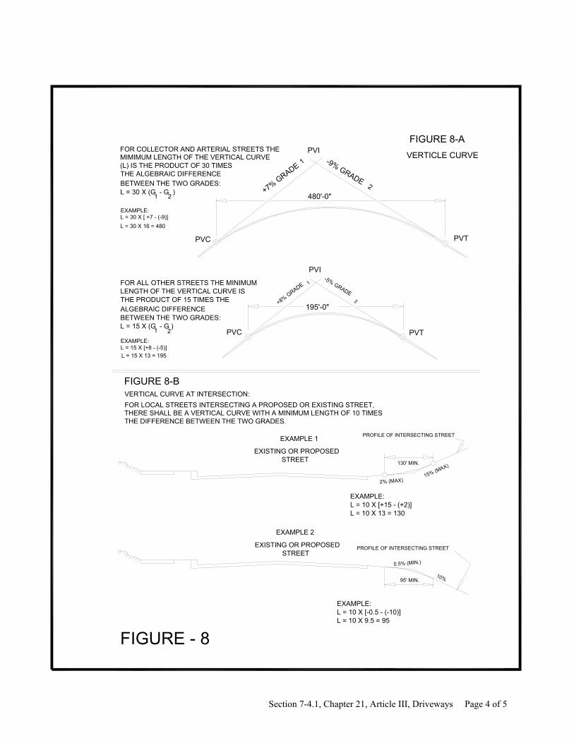
THE PRODUCT OF 15 TIMES THELENGTH OF THE VERTICAL CURVE ISFOR ALL OTHER STREETS THE MINIMUM
VERTICLE CURVE
FIGURE 8-A
(L) IS THE PRODUCT OF 30 TIMES
L = 30 X (G - G )1 2
1
2
L = 30 X [ +7 - (-9)]L = 30 X 16 = 480
ALGEBRAIC DIFFERENCEBETWEEN THE TWO GRADES:L = 15 X (G - G )
L = 15 X [+8 - (-5)]L = 15 X 13 = 195
1
2
PVI
PVC PVT
THE DIFFERENCE BETWEEN THE TWO GRADES.
EXAMPLE:
EXAMPLE:
PROFILE OF INTERSECTING STREETEXISTING OR PROPOSEDSTREET
FIGURE - 8
1 2
FIGURE 8-B
PROFILE OF INTERSECTING STREET
95' MIN.10%
0.5% (MIN.)
15% (MAX)
2% (MAX)
L = 10 X 9.5 = 95L = 10 X [-0.5 - (-10)]EXAMPLE:
EXAMPLE 2
L = 10 X 13 = 130L = 10 X [+15 - (+2)]EXAMPLE:
THERE SHALL BE A VERTICAL CURVE WITH A MINIMUM LENGTH OF 10 TIMESFOR LOCAL STREETS INTERSECTING A PROPOSED OR EXISTING STREET,
EXAMPLE 1
STREETEXISTING OR PROPOSED
VERTICAL CURVE AT INTERSECTION:
130' MIN.
+7% GRADE-9% GRADE
480'-0"
PVC PVT
PVI
195'-0"
-5% GRADE
+8% GRADE
BETWEEN THE TWO GRADES:THE ALGEBRAIC DIFFERENCE
MIMIMUM LENGTH OF THE VERTICAL CURVEFOR COLLECTOR AND ARTERIAL STREETS THE
Section 7-4.1, Chapter 21, Article III, Driveways Page 4 of 5

Section 7-4.1, Chapter 21, Article III, Driveways Page 5 of 5
Secs. 21-67 – 21-75. Reserved.
DIVISION 2. PERMIT Sec. 21-76. Required. It shall be unlawful for any person to construct or maintain a driveway approach in the city without first obtaining a permit. (Code 1964, / 25-33) Sec. 21-77. Application. Any person desiring to obtain a permit for driveway approaches shall file an application with the city engineer. This application shall be in writing upon forms provided by the city and shall contain information showing the type of construction, the length of the driveway, the exact location of the driveway and any other information which may be required by the city engineer. (Code 1964, / 25-34) Sec. 21-78. Prerequisites to issuance. The owner and contractor shall protect the public from injury or damage during the construction of driveway approaches and it is stipulated, as an essential condition of the issuance of a permit, that the city shall not be liable for damage which may arise from the prosecution of such work. (Code 1964, / 25-35) Sec. 21-79. Issuance; fees. Upon approval of such improvements, covered by this article, by the city engineer the applicant shall pay five dollars ($5.00) per fifteen (15) feet of driveway approach width or fraction thereof for the permit. (Code 1964, / 25-36) Sec. 21-80. No existing public sidewalks. Where standard curb and gutter have been installed but concrete sidewalks have not been installed, the permit may authorize the applicant to construct the driveway approach from the curbline to the applicant’s premises of the same materials as those used for paving the applicant’s premises, or of any other material satisfactory to the city engineer. Such driveway approach shall be constructed to the established grade and shall be adequate and suitable for the traffic to be carried by it. The permit shall provide and the applicant shall agree that if and when thereafter concrete sidewalks are constructed the applicant or his successor shall install concrete driveway approaches as specified in section 21-66. (Code 1964, / 25-40)

ORDINANCE NO. 2503
AN ORDINANCE TO REGULATE THE NUMBER, PLACEMENT AND CONSTRUCTION OF CURB-CUTS ALONG THE STATE OF FRANKLIN ROAD
WHEREAS, it is in the interest of the City of Johnson City to improve the safety and efficiency of State of Franklin Road as a major arterial; and WHEREAS, the Johnson City Regional Planning Commission has recommended adopting by ordinance a method to regulate the number and placement of curb-cuts on State of Franklin Road as a primary means of improving the safety and traffic carrying capacity of that arterial; THEREFORE, BE IT RESOLVED THAT the following regulations be enacted: Section 1. All curb-cuts connecting to State of Franklin Road providing ingress and egress to abutting properties shall be approved only after application to and review and approval by the City Engineer. Said application shall indicate the exact location of the proposed curb-cut, its dimensions, width, radii, its distances from property lines, and the location(s) of the nearest existing or proposed curb-cuts and/or street intersections within 100 feet of the curb-cut in either direction and on either side of State of Franklin Road. Section 2. Approval by the City Engineer shall be guided by the criteria that follow. Denial of a request for a curb-cut may be appealed to the Johnson City Regional Planning Commission by proper application made within ten days following the denial of the request, and the action of the Johnson City Regional Planning Commission may be appealed by either party to the Johnson City Board of Commissioners if either party believes the decision to be improper in any respect including, but not limited to, the interpretation of the criteria for granting a curb-cut, a unique hardship not self-imposed, and other like considerations. However, the Planning Commission and the City Commission shall evaluate the request and may grant the approval for a curb-cut only in conformance with the criteria that follow, and may allow leniency or any variance of these requirements only if the intent of these regulations is being substantially maintained. Section 3. All properties abutting the right-of-way of State of Franklin Road either existing or proposed as of the date of this ordinance and that abut another public right-of-way now or in the future, shall gain access from the alternative right-of-way and not State of Franklin Road. No subdivision of property shall take place from and after the passage of this ordinance that has the effect of creating a new lot or parcel of property with access solely from State of Franklin Road, unless such subdivision is approved by the Johnson City Regional Planning Commission. Section 4. Railroad right-of-way to accommodate trackage shall not be considered a lot or parcel for development purposes. Accordingly, such property shall not be granted curb-cuts for access purposes. Neither shall curb-cuts be granted to permit driveways across railroad right-of-way to developable lots or parcels. Said lots or parcels separated from State of Franklin Road by railroad right-of-way shall be considered not to have frontage on State of Franklin Road. Section 5. All properties along proposed State of Franklin Road between Buffalo Street and Tennessee Street currently have access to alternative public rights-of-way and are separated from the existing or proposed State of Franklin Road right-of-way by railroad right-of-way devoted to trackage. Therefore, no access to State of Franklin Road by way of new curb-cuts shall be approved in this area. Further, no subdivision of property except as may be
Section 7-4.2. Ordinance No. 2503, State of Franklin Road Page 1 of 2

Section 7-4.2. Ordinance No. 2503, State of Franklin Road Page 2 of 2
approved by the Johnson City Regional Planning Commission shall occur that would create a lot or parcel without access to a right-of-way other than State of Franklin Road. Section 6. Properties between Tennessee Street and VA Access Road currently having curb-cuts to State of Franklin Road shall be entitled to maintain these. Properties having access by way of other alternative rights-of-way shall use these alternative means of access. No additional access from State of Franklin Road shall be permitted and no subdivision of property shall occur to require access from State of Franklin Road. Vacant property north of and adjoining State of Franklin road may obtain access at three points: opposite and as extensions of Lake Drive, University Drive, and Sherrod Drive; subdivision of said property approved by the Johnson City Regional Planning Commission may occur to the extent access is limited to these three points only. Property currently occupied by First American Bank may maintain its existing curb-cuts. However, to the extent this development is integrated with future development on the adjacent vacant property and internal circulation permits adequate ingress and egress from the three curb-cuts to be developed opposite Lake Drive, University Drive and Sherrod Drive, then existing curb-cuts to the bank property may be removed. Section 7. Properties from VA Access Road to the proposed Southern Railway overpass shall be permitted access to State of Franklin Road if the properties currently have access only to Walnut Street, and the only available access is to State of Franklin Road after completion of construction. If access currently is available from alternative rights-of-way and remains available following construction, or if alternative access becomes available following construction, or if alternative access currently is available from alternative rights-of-way and remains available following construction, or if alternative access becomes available as a result of construction of State of Franklin Road, alternative access shall be used in lieu of curb-cuts to State of Franklin Road. Section 8. Access to State of Franklin Road from properties from the Southern Railway overpass to West Market Street shall be available only at median breaks, and at those points of ingress and egress provided as of the effective date of this ordinance. All vacant properties not having predetermined curb breaks on State o Franklin Road shall gain access only in accordance with plans for additional public right-of-way or private drives located at median breaks determined by the Tennessee Department of Transportation (TDOT), and spaced to met TDOT requirements of a minimum of 600 feet between median breaks. No curb-cuts shall be allowed at other locations unless same exist as of the effective date of this ordinance.
PASSED ON FIRST READING September 20, 1984 PASSED ON SECOND READING October 4, 1984 PASSED ON THIRD READING October 18, 1984 APPROVED AND SIGNED IN OPEN MEETING ON THE 18-th DAY OF October, 1984 Signed by: Raymond E. Huff, Mayor
Attest by: James H. Crumley, City Recorder Approved as to form by: James H. Epps, III

7-5. T-DOT Entrance Regulations

STATE OF TENNESSEE
DEPARTMENT OF HIGHWAYS
RULES AND REGULATIONS
For
Constructing Driveways on
State Highway Right of Way

RULES AND REGULATIONS
FOR CONSTRUCTING DRIVEWAYS
ON
STATE HIGHWAY RIGHTS-OF-WAY
Adopted by
TENNESSEE DEPARTMENT OF HIGHWAYS
Revised January 1, 1966
Effective April 3, 1967
TENNESSEE DEPARTMENT OF HIGHWAYS
Nashville, Tennessee 37219
II

FORWARD
The following rules and regulations are designed to afford easy and safe ingress and egress to roadside establishments adjacent to the State’s highways and to afford maximum protection to the traveling public,
and to insure a uniform system of construction on the State Highway right-of-way.
These rules and regulations are based on experience of the Tennessee Department of Highways and recommendations of the Committee on Planning and Design Policies of the American Association of State
Highway Officials.
III

I, Charles W. Speight, Commissioner of Highways, by virtue of the authority vested in me by Section 54-540, Tennessee Code Annotated, do hereby promulgate and publish rules and regulations as hereinafter set
forth relating to entrances into highways:
IV

TABLE OF CONTENTS
STATE HIGHWAY RIGHT OF WAY ...........................................................................................................................................I SECTION I - DEFINITION OF TERMS ......................................................................................................................................1
SECTION II - RIGHT-OF-WAY ENCROACHMENT ................................................................................................................1
SECTION III - SIGHT DISTANCE..............................................................................................................................................2
SECTION IV - NUMBER AND ARRANGEMENTS OF DRIVEWAYS...................................................................................2
SECTION V - DRIVEWAY WIDTH AND EDGE RADIUS.......................................................................................................3
SECTION VI - DRIVEWAY ALIGNMENT AND PROFILE .....................................................................................................3
SECTION VII - DRIVEWAY SURFACING................................................................................................................................3
SECTION VIII - CURBS AND GUIDE POSTS...........................................................................................................................3
SECTION IX - DRAINAGE .........................................................................................................................................................4
SECTION X - SIGNING...............................................................................................................................................................4
SECTION XI - CONTROL DIMENSIONS..................................................................................................................................4
SECTION XII - DRIVEWAY PROFILE......................................................................................................................................5
SECTION XIII - SKETCHES AND EXAMPLES........................................................................................................................5
SECTION XIV - PROCEDURE FOR OBTAINING PERMIT TO CONSTRUCT DRIVEWAY ON STATE HIGHWAY
RIGHT-OF-WAY........................................................................................................................................................................23
SECTION XV - BOND REQUIREMENTS................................................................................................................................24
ATTACHMENT B .....................................................................................................................................................................26
SECTION XVI – SAMPLE – HIGHWAY ENTRANCE PERMIT............................................................................................27
STATE OF TENNESSEE DEPARTMENT OF HIGHWAY ENTRANCE PERMIT................................................................27
SUPPLIMENT TO THE RULES AND REGULATIONS.....................................................................................................28
OPERATIONAL GUIDELINES.................................................................................................................................................29
VISITING OUR OFFICE............................................................................................................................................................35
V

SECTION I - DEFINITION OF TERMS Frontage – The length along the highway right-of-way line of a single property tract or roadside development area between the
edges of the property distance between (1) and (2) in Figures 1 and 2. Corner property at a highway intersection has a separate frontage along each highway.
Frontage Boundary Line (abbreviated as FB line) – A line, normal to the highway centerline, at each end of the frontage,
extending from the right-of-way line to the edge of through-traffic lane; line (1) – (4) or (2) – (3) in Figures 1 and 2.
Buffer Area – The border area along the frontage between the traveled way and the right-of-way line and within the frontage boundary lines areas (1) – (2) – (3) – (4) in Figures 1 and 2.
Driveway Width (W) – Narrowest width of driveway measured parallel with the edge of traveled way; W in Figures 1 and 2.
Driveway Angle (Y) – The angle of 90 degrees or less between the driveway centerline and the edge of the traveled way Y in
figures 1 and 2.
Edge Clearance (E) – The distance measured along the edge of the traveled way, between the frontage boundary line and tangent projection of the nearest edge of driveway; E in Figures 1 and 2.
Corner Clearance (C) - At an intersecting street or highway, the dimension measured along the edge of the traveled way between
the frontage boundary line opposite the intersection of the two right-of-way lines and the tangent projection of the nearest edge of driveway C in Figure 3.
Setback (G) – The lateral distance between right-of-way line and the roadside business building, gasoline pump curb base, display
stand or other object, the use of which will result in space for vehicles to stop or park between such facilities and the right-of-way line; G in Figure 2.
Outside Radius (R) – The outside or larger curve radius on edge of driveway R in Figures 1,2 and 3.
Distance Between Double Driveways (D) – The distance measured along the right-of-way line between the tangent projections of
the inside edges of two adjacent driveways to the same frontage; D in Figure 2.
General – For simplicity, the above definitions are stated in terms of single radius curves of edge of driveways or intersecting highways. Where compound curves or tapers are used an equivalent single radius curve may be used as a control guide.
SECTION II - RIGHT-OF-WAY ENCROACHMENT No part of the highway right-of-way should be used for servicing vehicles, displays, or the conducting of private business.
The buffer area is to be kept clear of buildings, fences, business signs, parking areas, service equipment, and appurtenances thereto. Parking may be permitted on the roadway, as at curbs on city streets, when permitted by police control. The buffer area may be graded and landscaped as approved by the Tennessee Department of Highways.
Buffer Areas
In the development of private property and the construction of driveways thereto, it may be necessary to regrade the buffer area by cutting or filling. Such work shall be done in a manner to insure adequate sight distance for traffic operations, proper drainage, suitable slopes for maintenance operations and good appearance. The buffer area outside the driveways should be treated to prevent use by vehicles. This may be accomplished b the grading, use of curbs, rails, guide posts, low shrubs, etc., in a manner that will not impair clear sight across the area.
Parking
Each roadside business establishment should provide parking or storage space off the right-of-way to prevent the storage of vehicles on the driveway or the backing up of traffic on the travel way. This is particularly needed for businesses where a number of vehicles will be leaving and entering at the same time.
Where there are one or more driveways to a corner establishment at a highway intersection, parking should be restricted on each highway between the intersection and the nearest driveway.
1

SECTION III - SIGHT DISTANCE Where feasible within the frontage limits, any driveway shall be located so as to afford maximum sight distance along the highway. Where a driveway is provided to a commercial establishment, the buffer area and adjacent border area shall be reasonably cleared so that either the establishment itself or an appropriate sign located outside the right-of-way can be seen at a sufficient distance to enable proper maneuvers on the part of the drivers desiring to enter the establishment. The profile of the driveway and the grading of the buffer area shall be such that a driver of a vehicle that is standing on the driveway may see a sufficient distance in both directions to enable him to enter the highway without creating a traffic hazard. Setbacks Improvements on property adjacent to the right-of-way should be so located that parking, stopping and maneuvering on the right-of-way will not be necessary in order for the vehicles or patrons to be served. Location of Driveways Driveways shall be so located that vehicles entering or leaving the establishment will not interfere with the free movement of traffic or create a hazard on the highway. Where feasible they shall be located where there are no sharp curves and steep grades and where sight distance is adequate for safe traffic operation. Driveways should not be located within intersections, rotaries and interchanges or on highways immediately approaching them. They shall be so located that they will not interfere with the placement of signs, signals or other devices that affect traffic operations.
SECTION IV - NUMBER AND ARRANGEMENTS OF DRIVEWAYS For property tracts with a sizable frontage on the highway, driveway location and arrangement largely will be governed by the position of installations thereon. Where driveways are provided to land areas only, i.e., areas with no developments sufficiently near the highway to significantly control driveway arrangements, they shall be located to best advantage with regard to the highway alignment, profile, sight distance conditions, etc. The permissible number, arrangements, and width of driveways shall be governed in part by the highway frontage of abutting private property. The number if driveways provided shall be the minimum number required to adequately serve the needs of the adjacent property. Frontages of 50 feet or less shall be limited to one driveway. Normally not more than two driveways will be provided to any single property tract or business establishment. Where there are several adjacent roadside establishments each with relatively limited frontage, or where there is probability of some development, consideration should be given to the provision of a frontage road for connecting driveways so as to reduce the number of separate connections to the highway. Where border width permits, the several driveways should be connected directly to such an outer road paralleling the highway with connections to the through highway only at the extremities of the frontage road or at well spaced intervals along it. Driveways shall be positioned to clear the frontage boundary lines by the specified minimum dimension. Where two driveways are provided for the one frontage, the clear distance be between driveways measured along the right-of-way line shall not be less than 25 feet. At an intersection of two highways a driveway connecting each highway with a corner property will be permitted where essential to the conduct of business on the corner tract, provided such driveways comply with the control dimensions set out in Section XI. Under urban condition, and elsewhere particularly where traffic in relation to capacity is high, the corner clearance on the approach to the intersection desirable should be greater than that on the far side of the intersection.
2

SECTION V - DRIVEWAY WIDTH AND EDGE RADIUS
The driveway width shall be adequate to handle properly the anticipated volume and type of traffic and shall be within the limits specified for the particular condition and type of establishment as set out in Section XI of these rules and regulations.
Where space permits, the radius of curve connecting the edge of through-traffic lane and edge of driveway shall be the maximum radius to permit turns by the largest vehicle to be expected with some frequency. For narrow frontage or narrow border conditions the combination of driveway width and edge radius of smaller dimension should be adequate to this end. The radii for driveways on streets on which there are outer parallel parking lanes shall be based on turns from the edge of through lane, and parking should be regulated as necessary to keep the turning area free of standing vehicles.
SECTION VI - DRIVEWAY ALIGNMENT AND PROFILE
Single driveways should be positioned at right angles to the roadway. Where two driveways are used on one frontage, and they are to be used for access to and from both directions of travel on the highway, each roadway shall be at right angles with the centerline of the roadway as specified in Sketches and Examples. The driveway angle may be between 45 degrees (min.) and 60 degrees (max.) when the driveway is to be used by vehicles in only one direction of highway travel (right turns only) on a divided highway.
On uncurbed sections of highway the gradient of the driveway shall conform with the normal shoulder pitch from the edge of the traveled way to the outer shoulder line and thence slope downward on a suitable grade to the gutter or low point over a culvert (swale where a culvert is not used). Thereafter it shall continue downward or roll upward depending upon the level of its destination with respect to the shoulder.
Where curbs are used along the roadway and sidewalks are provided or contemplated, the gradient of the driveway usually shall fit the plane of the sidewalk. If the difference in elevation of the gutter and the sidewalk is such that this is not practical, then the sidewalk shall be lowered to provide a suitable gradient for the driveway in such case the surface of the sidewalk should be sloped gently from either side of the driveway.
Vertical curves on driveways should be flat enough to prevent dragging of central or overhang portions of passenger vehicles.
SECTION VII - DRIVEWAY SURFACING
Where the driveway is to be paved with concrete or bituminous material its depth shall be a minimum of six inches or the depth of the existing travel way, whichever is the greatest. This depth shall extend from the travelway to the back of the ditch line or ten feet from the edge of the shoulder line as the case may be. Gravel surface may be suitable for some locations and no surfacing will be required for residential and field driveway in rural areas.
SECTION VIII - CURBS AND GUIDE POSTS
Curbs of the type specified by the Tennessee Department of Highways shall be used on the driveway and on islands within the buffer area, but all such curbs shall be outside the limits of the shoulders where the traveled way is not curbed. Where the traveled way is curbed, the returns of the driveway shall join properly the curb of the traveled way.
It is desirable that all curbs be placed 26 feet from the centerline of the existing roadway where insufficient right-of-way, the location of existing curb and gutter, or a pavement in excess of 48 feet in width, does not preclude the use of this location. Final location of the curb is subject to the approval of the Regional Engineer.
3

SECTION IX - DRAINAGE
All driveways and buffer areas shall be constructed so as not to impair drainage within the highway right-of-way nor alter the stability of the roadway subgrade and at the same time not impair or materially alter drainage of the adjacent areas. All culverts, catch basins, drainage channels, and other drainage structures required within the buffer area and under the driveways as the result of the property being developed shall be installed in accordance with standards of the Tennessee Department of Highways.
SECTION X - SIGNING
All advertising structures, advertising signs or advertisements shall be located outside the highway right-of-way limits and shall in all cases comply with Tennessee laws regulating outdoor advertising.
SECTION XI - CONTROL DIMENSIONS
Edge Clearance (E) (Rural and Urban): GENERAL: All portions of the driveway shall be within the frontage boundary line. For driveways with angles of about
90degrees, the edge clearance should not be less than the radius of curvature (R) for the junction of the driveway and pavement (shoulder) edges.
Rura1 Residential: 5 feet Minimum Rural Commercial: 12.5 ft. Minimum Urban Residential: 5 feet Minimum Urban Commercial: 12.5 ft. Minimum
Width (W) (Rural and Urban): Residential: 10 feet Minimum; 20 feet Maximum Commercial: 20 feet Maximum; for one-way use
40 feet Maximum; for two-way use. Driveway Angle (Y) (Rural and Urban):
Driveways for two-way operation: 90 degrees to centerline of roadway
Driveways for one-way operation: 1. Driveways used by vehicles in both directions of travel on highway; Same as for two-way operations (90
degrees to centerline of roadway.) 2. Driveways used by vehicles in one direction of travel on divided highway (right turn only) 60degrees
Maximum, 45 degrees Minimum. Radius of Curvature (R) (Rural and Urban):
Rural Residential: 5 feet Minimum; 20 feet Maximum Rural Commercial: 5 feet Minimum; 20 feet Maximum Urban Residential: 5 feet Minimum; 15 feet Maximum Urban Commercial: 5 feet Minimum; 20 feet Maximum
Distance Between Double Driveway (D) (Rural and Urban): Rural: 25 feet Minimum Urban: 25 feet Minimum
NOTE: IN NO CASE SHALL THE DISTANCE (D) BE LESS THAN THE LARGEST ADJACENT WIDTH OPENING (W) . Corner Clearance (C) (Rural and Urban):
Rural: 30 feet Minimum Urban: 25 feet Minimum Where there are traffic signals at the intersection, desirably the nearside clearance should be two or more times the far side.
4

SECTION XII - DRIVEWAY PROFILE
No Highway Edge Curb, cut section: (a) from edge of traveled way to outer edge of shoulder, gradient same as shoulder pitch (b)
from outer edge of shoulder to low point at ditch line or over culvert maximum downward gradient 5 to 8 percent; (c) beyond ditch line, maximum gradient 5 to 8 percent for commercial driveways or 10 to 15 percent for others.
No Highway Edge Curb, fill section: (a) slope across shoulder, same as above (b) beyond outer edge of shoulder, maximum
gradient 5 to 8 percent for commercial driveways or 10 to 15 percent for others. With Highway Edge Curbs: Driveway profile should slope upward from gutter line to meet the sidewalk, if any, with maximum
difference between downward cross slope of traveled way and upward slope of driveway of 8 to 10 percent; beyond outer edge of walk or equivalent, maximum gradient equal 5 to 8 percent for commercial driveways or equal 10 to 15 percent for others.
Vertical Curve: As fiat as feasible: To prevent drag, vertical curves should avoid a hump or dip greater than about 6 inches within
wheel base length of 10 feet. For recent model passenger cars, to prevent center or overhang drag, with some allowance for load and bounce, crest vertical curves should not exceed a 3-1/4-inch hump in 10-foot chord and sag vertical curves should not exceed a 2-inch depression in 10-foot chord.
SECTION XIII - SKETCHES AND EXAMPLES
Figures 1 and 3 - Sketches illustrating definitions.
Figure 4 - Sketch for profile controls.
Figures 5 to 16 - Typical plans showing control dimensions. Figures 1 to 3 and 5 to 11 are drawn for rural highways with
the edges of highway traveled ways shown by a single heavy line. This heavy line does not represent a curb or other form of barrier between the highway traveled way and the shoulder area which is shown stippled. Driveways are shown as double line connections to the outer edge of the shoulder. In the case of urban highways Figures 12 to 16, a double line is used to indicate curbs, as usually would be provided, at the edge of traveled way.
Figure 4 shows typical driveway profile controls for rural and urban driveways. The uses of a swale or pipe underdrain for proper drainage of highways are indicated. The bottom profile shows the driveway sloping upward to the sidewalk to assure proper drainage. Beyond the sidewalk the driveway may slope either upward or downward depending upon the topography at the site.
Figures 5 through 16 are layout sketches for some of the usual conditions of driveway connections. It is not feasible to
include herein detail sketches for all likely combinations of the several factors and conditions but the major cases are illustrated. The range of control dimensions previously listed is shown on these sketches wherever pertinent. Details of the private property developments, shown only in part, are not intended to be realistically complete.
Figure 5 shows a single-residence driveway along a rural two-1ane highway. In such case the frontage usually is not a
governing factor but edge clearance is a control. Figure 6 shows a single driveway connection to a commercial establishment along a two-lane rural highway. While a
small development area is shown, the same treatment would apply for a much larger site. Figure 7 shows a double driveway connection to a rural corner roadside business along a four-lane divided highway
crossed by a two-lane highway. The double driveways are governed by a limited frontage for the business area. Each of the driveways is patterned for two-way operation. One-way operation is preferable. On the crossroad there is n single 90 degree driveway. Minimum corner clearance is shown.
Figure 8 shows double driveway connection to a sizable roadside development along a two-lane rural highway. Figure 9 shows a corner service station at a rural intersection of two-lane highways. There is a single driveway to each
highway, located on an angle and with reasonably adequate corner clearance.
Figure 10 is a diagrammatic indication of progressive development in the grouping of driveways along a rural nondivided highway. Stage 1 is without roadside developments. In Stage 2 a few reasonable well spaced driveways have been provided. Under stage 8 conditions there are 8 separate driveways across the right-of-way line and the group has been combined by providing a frontage road, with connections only at its terminals.
5

Figure 11 shows typical driveway connections to a drive-in theater from a rural two-lane highway. Note the two-1ane
entrance roadway to provide space for vehicle stored to avoid vehicle backup on the highway. In this case widths are basic roadway elements the connections to the highway would be designed as an intersection at grade. Control values for R and D would apply.
Figure 12 shows an urban residential driveway. In such case the property frontage for a single residence often is a limiting dimension and edge clearance also is significant. Minimum dimensions usually apply.
Figure 13 shows driveway connections to a commercial or industrial establishment in an urban or suburban area. There is
a single entrance from the main street and a secondary entrance from the side street. Curbed street sections are shown, and there may or may not be sidewalks. Desirably the near-side corner clearance should be two to three times the minimum.
Figure 14 shows a double driveway entrance to a service station or other roadside business for the usual urban conditions
of narrow border, curbed roadway, sidewa1ks, and limited frontage. For such cases the driveway has no element of length along the driveway; primarily it is a ramp pavement from street edge to business area at the right-of-way line. Often a sidewalk is crossed affecting the profile condition. Functional utility of the driveway largely depends upon width of opening at the curb line. Edge clearances are important since similar driveways may be necessary on adjacent properties.
Figure 15 shows a street corner service station with a single driveway to each street. Details are similar to those in the
previous figure except that corner clearances also controls. Figure 16 is another street corner layout similar to the previous case, but with a double driveway on the major street.
6


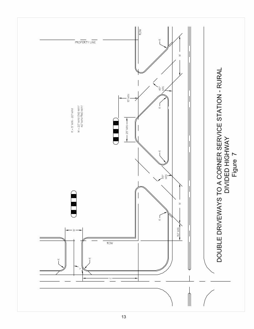


Figure 11
The original document contained a figure showing a driveway entrace to a drive−in movie theater. It is not included since drive−in theaters are not commonplace anymore.


SECTION XIV - PROCEDURE FOR OBTAINING PERMIT TO CONSTRUCT DRIVEWAY ON STATE HIGHWAY RIGHT-OF-WAY
Applications for driveway permits shall be forwarded to the State Highway Department, Regional Engineer's office at one of the following locations nearest the construction:
Knoxville, Tennessee-711 Concord Street, Phone 525-8481
Chattanooga, Tennessee-Cromwell Road, Phone 892-3430 Nashville, Tennessee-2200 Charlotte Avenue, Phone 741-4132 Jackson, Tennessee-State Street, Phone 424-4110
The owner of the property to be served shall file application and said application should have the following listed information to facilitate handling:
1. Location of property 2. Plot plan of property s. Copy of deed (proof of ownership) 4. Explanation of proposed usage of property 5. Any other information that might affect the access design.
The Regional Engineer shall make a complete field review of the application and shall prepare the framework of the applicable sections of these rules and regulations, an 8-1/2" x 11" drawing the design proposed for the location. The drawing showing the design approved for the location, together with three copies of a proposed permit shall be submitted to the owner for review and acceptance. The owner shall sign each copy of the proposed permit and shall return all copies to the Regional Engineer for further handling. Applicable bond, as outlined in Section XV of these rules and regulations and a certificate of insurance as required in the permit shall be submitted along with the signed permit.
The Regional Engineer, acting for the Commissioner of Highways and the State Highway Engineer, will approve the permit and shall forward a fully executed copy of the permit to the owner. Receipt of a fully executed copy of the permit shall be the owners authority to begin construction. The Regional Engineer shall make the following distribution of the approved permit: 1. Regional Engineer - maintain original, 2. Owner - one copy, 3. Highway Accounts - one copy and cash bond*, *Copy of approved permit to be furnished Highway Accounts, only when a Cash Bond is used.
23

SECTION XV - BOND REQUIREMENTS I. Posting of Bond.
All permits covering construction of driveway (s) on State Highway Rights-of-Way shall be accompanied by a bond executed by the owner with good and sufficient surety, acceptable to the Tennessee Department of Highways, guaranteeing the performance of the terms and conditions of the permit.
The owner may select one of the following procedures :
1. Post a cashier’s or certified check in an amount not less than one hundred dollars ($100) and not more than five hundred dollars ($500). The actual amount of the bond to be established by the Regional Engineer after Consideration of the type and amount of construction to be performed, or
2. Post a Surety Bond; however a Surety Bond for an amount less than Two Thousand, Five Hundred Dollars ($2,500) will not be acceptable; or
3. Post a Statewide Bond (Running Surety Bond) in the amount of Ten Thousand Dollars ($10,000) to cover all such authorized work on the State Highway Rights-of-Way for a specified period of time. NOTE: ALL SURETY BONDS SHALL BE ON FORMS SUPPLIED BY THE TENNESSEE DEPARTMENT OF HIGHWAYS AND MAY BE OBTAINED FROM THE REGIONAL ENGINEER, STATE HIGHWAY DEPARTMENT, KNOXVILLE, CHATTANOOGA, NASHNILLE OR JACKSON, TENNESSEE.
Form TE: l Surety Bond II. Examples of Bond Forms:
(See Attachments A & B) III. Bond Release or Refund:
Upon completion of the authorized construction the owner shall notify the State Highway Department, Regional Engineer's office that issued the permit for construction.
The Regional Engineer shall inspect the site to ascertain that all construction complies with the terms and conditions of the
permit covering the work and that the construction has been satisfactorily completed. The Regional Engineer shall advise the owner and his Liability Insurer, in writing that it is no longer necessary to maintain the Liability Insurance required under the terms of the permit issued to the owner for this construction.
Following lapse of the time period specified in the permit, the Regional Engineer shall make final inspection of the site to
ascertain that all construction has been maintained to design specifications. In the event the Regional Engineer considers the construction satisfactory, he shall prepare Form F-600 directing the Division of Highway Accounts to refund any cash bond, or if a Surety Bond that has been posted, the Regional Engineer shall advise the owner and the bonding agency by letter that the construction has been accepted by the State.
24

ATTACHMENT A Form TE: 1 (Rev. 9-29-75)
HIGHWAY ENTRANCE PERMIT SURETY BOND NO. ___________________ PERMITTEE _________________________________________ STATE ROUTE_______________________________________ COUNTY ___________________________________________ KNOWN, ALL MEN BY THESE PRESENTS:
That we,______________________________________________________________________ PRINCIPAL, (PERMITEE)
and ________________________________________________________________________________as SURETY, are held and firmly bound unto the DEPARTMENT OF TRANSPORTATION, BUREAU OF HIGHWAYS of the State of Tennessee to construct the improvements on the State highway right-of-way at the location and in the manner shown on the plans attached to the Permit dated the ______________ day of __________________ , 20_______, issued to the BUREAU OF HIGHWAYS of the STATE OF TENNESSEE to the PRINCIPAL herein, which said Permitted plans are attached hereto. We do hereby further agree that we will restore to its original condition any portion of the pavement, shoulders or other parts of the public highway, except as otherwise shown on said plans, in the event that same is damaged by the PRINCIPAL or his agents during construction of said improvement and that we will maintain said improvements upon said right-of-way in such manner and for such period of time as provided in said Permit. In the event such construction, repairs and maintenance are not carried out in a manner satisfactory to the BUREAU OF HIGHWAYS of the STATE OF TENNESSEE, we hereby agree to reimburse said BUREAU for the cost of such repairs.
We do bind ourselves in the sum of _________________________________Dollars ($____________ ) for a term beginning the ______________ day of _____________________, 20______, until proper release is release from the BUREAU OF HIGHWAYS of the STATE OF TENNESSEE, as provided in said Permit and the RULES AND REGULATIONS FOR CONSTRUCTION OF DRIVEAYS ON STATE HIGHWAYS RIGHTS-OF-WAY as promulgated by the Commissioner of DEPARTMENT OF TRANSPORTATION. NOW, THEREFORE: the PRINCIPAL and SURETY assume all obligations and liabilities as set forth above. SIGNED, SEALED and DATED this the _______________ day of ______________________________, 20________. SURETY COMPANY ____________________________ ADDRESS______________________________ ______
____________________________________ All correspondence should be forwarded To: Bureau of Highways, P.O. Box 58
Knoxville, Tennessee 37901 Attention: Mr. Mark Best, Operations Spec.
Supervisor 2 Traffic Engineering Office
______________________________________________ PRINCIPAL
BY____________________________________________
______________________________________________ SURETY BY____________________________________________
(A copy of the Power of Attorney properly executed by the Company authorizing the Agent signing above to bind the Company as Surety on this Bond must be attached hereto. Said Power of Attorney shall be dated so as to correspond with the execution date of the bond).
25

ATTACHMENT B
The original document contained a blank form, TE: 2, “RUNNING SURETY BOND” on this page. It is not included since the current permit instructions do not include a Running Surety Bond.
26

SECTION XVI – SAMPLE – HIGHWAY ENTRANCE PERMIT
STATE OF TENNESSEE DEPARTMENT OF HIGHWAY ENTRANCE PERMIT
The original document contained a sample permit form on this page and the next. An updated version is provided in the following section.
27

SUPPLIMENT TO THE RULES AND REGULATIONS FOR
CONSTRUCTING DRIVEWAYS ON STATE HIGHWAY RIGHT OF WAY
TENNESSEE DEPARTMENT OF TRANSPORTATION REGIONAL ONE TRAFFIC OFFICE
HIGHWAY ENTRANCE PERMIT OPERATIONAL GUIDELINES
28

29
TENNESSEE DEPARTMENT OF TRANSPORTATION REGION ONE TRAFFIC OFFICE
HIGHWAY ENTRANCE PERMIT
OPERATIONAL GUIDELINES
• Permits are not issued for undeveloped property. A detailed site plan is required. • Entrance widths: Minimum 24 feet and Maximum 40 feet. Entrances of 20 feet will be allowed
as one-way only. • Entrance radius: Minimum 15 feet and Maximum 50 feet. Radius should be as flat as possible
for ease of maneuver. • All entrances should be a minimum of 100 feet from county roads/city streets if possible. • For developments on a divided highway, the entrance should line up with a crossover. If they
cannot line up with a crossover, then a minimum of 100 feet is required between the entrance and the cross-over. (See Sketch 1). If the 100-foot distance cannot be obtained, then the entrance should be constructed as a right in/right out with a painted or concrete island.
• Turn lanes are recommended where design permits. • Joint-use agreements are used when two owners will be sharing one entrance. • For improvements to State Routes due to a new entrance, i.e. turn lanes, a complete overlay is
required by the permittee. Grinding of the pavement is not permitted on State Routes. • All pavement markings and signing shall conform to the Manual on Uniform Traffic Control
Devices (MUTCD). • Where entrances are constructed in curb and gutter sections, the tie-in to the curb should be as
flat as possible to allow ease of movement into the entrance. • No parking is allowed on State Right-of-Way. • Traffic studies may be required for larger developments based on trip generation.

TENNESSEE DEPARTMENT OF TRANSPORTATIONREGION ONE - KNOXVILLE
PAVEMENT TYPICAL SECTIONS
1" SURFACE (D MIX)
3" BINDER
6" BASE STONE
411-01
307-02
303-01
LIGHT (DRIVEWAY) PAVING
A
B
TENNESSEE DEPARTMENT OF TRANSPORTATIONREGION ONE - KNOXVILLE
PAVEMENT TYPICAL SECTIONS
ROADWAY (MEDIAN) PAVING
1 14" SURFACE (D MIX)
2 14" BINDER
3 12" (A - S MIX)
8" BASE STONE
411-01
307-02
307-01.03
303-01
30

STATE OF TENNESSEE
DEPARTMENT OF TRANSPORTATION REGION ONE TRAFFIC DEPARTMENT
7345 REGION LANE KNOXVILLE, TENNESSEE 37914
MEMORANDUM TO: Land Developers
Consultant Engineers Contractors
FROM: Mark Best Operations Specialist Supervisor 2, Traffic Office
DATE: January 1, 2000 SUBJECT: Highway Access Design Criteria
Deceleration Lanes, Tapers, and Median Crossover Improvements
Please be advised that prior to submitting a formal application for access onto the state highway system and/or soliciting bids from contractual firms for constructing such access, a preliminary site plan should be submitted to Mr. David Moore in my office. The Department of Transportation requires many commercial developments to include shoulder decel/accel lanes/tapers in their site developments. Further, it may be necessary to include modifications in the median crossover section if such exists adjacent to your development site. Due to variable roadway features/conditions at different locations and the scope of the proposed developments, it is time-saving for all concerned if the preliminary plan is submitted a reasonable period of time prior to the development plans, construction, etc., commencing. Any questions concerning this matter should be directed to Mr. David Moore at 865-594-9170. Your assistance with this review process will reduce the time involved in finalizing a highway entrance permit application. MB/js
31

STATE OF TENNESSEE
DEPARTMENT OF TRANSPORTATION REGION ONE TRAFFIC DEPARTMENT
7345 REGION LANE KNOXVILLE, TENNESSEE 37914
MEMORANDUM TO: All Applicants
FROM: Mark Best SUBJECT: Application for Highway Access The enclosed documents contain information necessary to secure a Highway Entrance Permit and also details the proper processing of the Highway Entrance Permit Application. State law provides the Department of Transportation with the authority to control access into the State highway system. The fully approved permit gives the owner of the property being developed the authority to perform construction on the highway right-of-way. So, please be sure that each step of the permit application is in the name of the property owner (not a lessee, independent developer or contractor). The State will require an engineering site plan prepared by a professional engineering or architectural firm. Please contact this office (prior to submitting the completed application) if there are any questions regarding the permit requirements.
32

PROCEDURE FOR ATTAINING APPROVAL TO CONSTRUCT DRIVEWAYS
ACROSS STATE HIGHWAY RIGHT OF WAY
PLEASE READ CAREFULLY Dear Applicant: This packet contains the application forms for a Highway Entrance Permit. This permit (issued to the owner of the property being developed) is the legal authorization required for performing driveway construction on State highway rights-of-way. State law requires an approved highway entrance permit for any driveway construction on State highway rights-of-way. The construction must conform with state (and local, where applicable) design standards. Attached you will find:
Four (4) Copies….Form TE-4 (Highway Entrance Permit) which must be signed by the property owner in the lower right-hand corner on the line designated "Permittee".
One (1) copy…… Form TE-1 (Surety Bond) the property owner must also post a
performance bond to insure that the driveway construction will conform to the permit design criteria. The bond can be in one of two forms:
A. A $2,500 surety bond (issued on Form TE-1 by an authorized insurance agent) or
B. A cash deposit of $500. If the property owner prefers to submit the cash deposit, it must be in the form of the cashier's or certified check (made out to the Tennessee Department of Transportation).
Another requirement is that the property owner is to submit proof of liability insurance coverage in the form of a certificate from the issuing agent. The coverage is as follows:
General Liability: $300,000.00 EACH PERSON $1,000,000.00 PER CLAIM
Said coverage is to cover equally personal injury as well as property damage. SITE DEVELOPMENT PLAN The Department, by law, has the authority to require the permit applicant to submit an engineering site development plan (drawn to an engineering scale) in advance of the anticipated development of the property. (Continued)
33

Any development larger than one half acre will require a grading/drainage plan also. Two (2) copies of each are to be submitted to Tennessee Department of Transportation for preliminary design review. If revisions are necessary, a copy of the preliminary plan will be marked with necessary changes and returned to the applicant with a written clarification. Once the particulars are resolved for the site development plan, five (5) copies of the revised plan are to be resubmitted. NOTE FOR DESIGNERS: If a grading/drainage plan is required, the proposed drainage is to be formulated by using SCSM Release Number 55 (soil conservation service method). If water retention is required, design of retention basins should be based on a 10-year pre-development flood and 50-year post-development flood. When the property that is being developed is located within the corporate limits of a city or in a county that maintains a planning/zoning board, a copy of the preliminary plan shall be submitted to the local authorities to allow a local review to occur simultaneously with the Tennessee Department of Transportation. The State will coordinate with the local authorities in the design review before accepting the plan for construction purposes or requesting revisions to be made by the permit applicant. Some small rural developments can be allowed to waive the site plan requirements and the Department of Transportation will provide a driveway layout when returning the approved permit to the applicant. T.D.O.T. officials will make this determination after discussing the scope of development with the property owner. A form drawing is attached and all blanks must be filled in or the application will be rejected. This information is vital since T.D.O.T. will be providing the site plan for these smaller developments. The permit application can either be mailed to the Department of Transportation for processing or can be hand carried if a time problem exists. This processing stage cannot be conducted until the site development plan has been reviewed by the State (and local authorities, if applicable) and revised/accepted for construction purposes. Applications being mailed in are to be directed to:
David Moore Traffic Office Department of Transportation P.O. Box 58 Knoxville, TN 37901 Telephone 865-594-9170
(continued)
34

Highway Entrance Permits are issued by the Region One Traffic Office, 7345 Region Lane, Knoxville, TN 37914
VISITING OUR OFFICE Please call our office (865-594-9170) prior to hand-delivering a permit application. The Department of Transportation Region One office is located in East Knox County at Exit 398 (Strawberry Plains Pike) on Interstate 40. Turn on Region Lane (from Strawberry Plains Pike) in front of Burger King and drive to the main (administration) building. The receptionist in the ground floor lobby will notify our office of your arrival. Check and be sure the application contains the following items before it is submitted for processing: A. Four (4) copies of Form TE-4 (permit) signed by the property owner as Permittee. B. Performance bond in the name of property owner. C. Insurance coverage in the name of the property owner or contractor. D. Five (5) copies of geometric site plan. E. Two (2) copies of detailed grading and drainage plan.
35


NOTICE TO BONDING AGENTS
THE FOLLOWING INFORMATION MUST BE DENOTED ON ALL PERFORMANCE BONDS SUBMITTED TO THE DEPARTMENT OF TRANSPORTATION (HIGHWAY ENTRANCE PERMITS). (1) NAME OF PRINCIPAL (MUST BE THE OWNER OF THE PROPERTY BEING DEVELOPED). (2) STATE ROUTE NUMBER (THAT THE PROPERTY FRONTS ON). (3) COUNTY (THAT THE SITE IS LOCATED IN). TO INSURE EXPEDIENT PROCESSING OF A REQUEST FOR, CANCELLATION (ONCE THE ENTRANCE WORK IS COMPLETED), THE AGENT MUST INCLUDE THE ABOVE INFORMATION ON THE RELEASE REQUEST. A SPACE IS PROVIDED IN THE UPPER LEFT CORNER OF THE BOND FORM FOR LISTING THIS INFORMATION. THE DEPARTMENT WILL NOT POST OR PROCESS ANY BOND OR RELEASE REQUEST THAT DOES NOT CONTAIN THIS REFERENCE INFORMATION.
41

Form TE: 1 (Rev. 9-29-75)
HIGHWAY ENTRANCE PERMIT SURETY BOND NO. ___________________ PERMITTEE _________________________________________ STATE ROUTE_______________________________________ COUNTY ___________________________________________ KNOWN, ALL MEN BY THESE PRESENTS:
That we,______________________________________________________________________ PRINCIPAL, (PERMITEE)
and ________________________________________________________________________________as SURETY, are held and firmly bound unto the DEPARTMENT OF TRANSPORTATION, BUREAU OF HIGHWAYS of the State of Tennessee to construct the improvements on the State highway right-of-way at the location and in the manner shown on the plans attached to the Permit dated the ______________ day of __________________ , 20_______, issued to the BUREAU OF HIGHWAYS of the STATE OF TENNESSEE to the PRINCIPAL herein, which said Permitted plans are attached hereto. We do hereby further agree that we will restore to its original condition any portion of the pavement, shoulders or other parts of the public highway, except as otherwise shown on said plans, in the event that same is damaged by the PRINCIPAL or his agents during construction of said improvement and that we will maintain said improvements upon said right-of-way in such manner and for such period of time as provided in said Permit. In the event such construction, repairs and maintenance are not carried out in a manner satisfactory to the BUREAU OF HIGHWAYS of the STATE OF TENNESSEE, we hereby agree to reimburse said BUREAU for the cost of such repairs.
We do bind ourselves in the sum of _________________________________Dollars ($____________ ) for a term beginning the ______________ day of _____________________, 20______, until proper release is release from the BUREAU OF HIGHWAYS of the STATE OF TENNESSEE, as provided in said Permit and the RULES AND REGULATIONS FOR CONSTRUCTION OF DRIVEAYS ON STATE HIGHWAYS RIGHTS-OF-WAY as promulgated by the Commissioner of DEPARTMENT OF TRANSPORTATION. NOW, THEREFORE: the PRINCIPAL and SURETY assume all obligations and liabilities as set forth above. SIGNED, SEALED and DATED this the _______________ day of ______________________________, 20________. SURETY COMPANY ____________________________ ADDRESS______________________________ ______
____________________________________ All correspondence should be forwarded To: Bureau of Highways, P.O. Box 58
Knoxville, Tennessee 37901 Attention: Mr. Mark Best, Operations Spec. Supervisor 2
Traffic Engineering Office
______________________________________________ PRINCIPAL
BY____________________________________________
______________________________________________ SURETY BY____________________________________________
(A copy of the Power of Attorney properly executed by the Company authorizing the Agent signing above to bind the Company as Surety on this Bond must be attached hereto. Said Power of Attorney shall be dated so as to correspond with the execution date of the bond)
42

40
HIG
HWAY
FRO
NTAG
E
SOLI
D W
HITE
LIN
EED
GE
OF D
RIVI
NG S
URFA
CEDR
IVIN
GLA
NE
PROPERTY LINE
PROPERTY LINE
PROP
ERTY
L
INE
PAVE
D SH
OULD
ER
CENT
ER L
INE
OF H
IGHW
AY
*
EDG
E OF
DRI
VING
SU
RFAC
E
IF T
HE H
IGHW
AY IS
A 4
−LANE F
ACIL
ITY,
IS T
HERE A
GRASS
OR C
ONCRETE
MEDIA
N D
IVID
ER S
ECTIO
N?
YES
NO
IF A
MEDIA
N D
IVID
ER S
ECTIO
N IS
IN
PLACE, SH
OW
DIS
TANCE F
ROM Y
OUR
PROPE
RTY
TO N
EAREST
MEDIA
N
CROSS
OVE
R (__
____
FT.)
STATE R
OUTE #
CIT
YCOUN
TY
NAME A
ND T
YPE O
F BUSI
NESS
PROPE
RTY
OW
NER (PR
INT)
YES
NO
LIST
NEAR−B
Y LA
NDMARKERS
(SUCH A
S SI
DE R
OADS,
BUSI
NESS
ES,
ECT.)
INDIC
ATE L
OCATIO
N(S
) OF
DRIV
EW
AY(S
) THAT Y
OU
ARE R
EQUEST
ING (T.D
.O.T
. WIL
L MAKE F
INAL
DETERMIN
ATIO
N F
OR
DRIV
EWAY
LOCATIO
N(S
))
HAS
PROPE
RTY
GONE
THROUGH Z
ONIN
G
PROCESS
WIT
H T
HE
LOCAL
AUTHORIT
IES?
APP
ROXIM
ATE A
CREAGE
BEIN
G D
EVE
LOPE
D
IS Y
OUR P
ROPE
RTY:
ROAD L
EVE
L................
ABOVE T
HE H
IGHW
AY....
BELO
W T
HE H
IGHW
AY....
___
FT.
___
FT.
___
FT.
___
FT.

GRA
SS O
R RA
ISED
MED
IAN
EDG
E OF
TRA
VEL
LANE
X-OV
ER
(SOL
ID W
HITE
LIN
E)
EXIS
T. S
HLD.
14'
ASPH
ALT
PAVI
NG
100'
MIN
IMUM
24' T
O 40
' MAX
AT T
HE R
OW
PROPERTY LINE
12 1 2'
MIN
IMUM
FRO
M P
ROPE
RTY
LINE
RIG
HT O
F W
AY
1
C S
.R.
L
____
FT.
STAT
E RO
UTE
#
SCAL
E: N
OT T
O SC
ALE

C S
.R.
EDG
E OF
TRA
VEL
LANE
(SOL
ID W
HITE
LIN
E)
EXIS
T. S
HLD.
ASPH
ALT
PAVI
NG
100'
MIN
IMUM
CO. RD. OR CITY STREET
100'
MIN
IMUM
IF P
OSSI
BLE
RIG
HT O
F W
AY
2
L
14'
____
FT.
STAT
E RO
UTE
#
SCAL
E: N
OT T
O SC
ALE

7-6. Lighting Regulations

ORDINANCE NO. 3688
AN ORDINANCE TO AMEND THE ZONING CODE OF THE CITY OF JOHNSON CITY REGARDING LIGHTING REGULATIONS.
WHEREAS, the Board of Commissioners of the City of Johnson City wishes to take measures to protect its citizens and their property from avoidable glare and excessive lighting; and WHEREAS, the aforementioned Board of Commissioners finds in the manifest best interest of the citizens of Johnson City to enact regulations on the use of lighting in furtherance of said objective; and WHEREAS, the Board of Commissioners find the enactment of such Lighting Regulations to be necessary for the health, safety, and welfare of the citizens of Johnson City. NOW, THEREFORE, BE IT ORDAINED BY THE CITY OF JOHNSON CITY AS FOLLOWS: SECTION 1. That the Zoning Code of the city of Johnson City be and the same is hereby amended and modified as follows: A. Article II be amended to include the following: ANGLE OF INCIDENCE: The angle at which a light ray strikes the surface,
measured between the ray and a line perpendicular to the surface. BAFFLE: An opaque or translucent element used to shield a light source from
direct view at certain angles, to absorb or block obtrusive light, or to reflect and redirect light.
BARE LAMP: A light source with no shielding. For the purposes of this Code, the
bare lamp of a luminaire is assumed to be the arc tube or filament in a clear lamp, or the first sight of a lamp in the case of frosted lamps.
BEAM ANGLE: The angle between the two directions for which the intensity is
50% of the maximum intensity as measured in a plane through the nominal beam centerline. For beams that do not have rotational symmetry, the beam angle is generally given for two planes at 90°, typically the maximum and minimum angles.
COSINE LAW: The law that the illuminance on any surface varies as the cosine of
the angle of incidence (see HORIZONTAL ILLUMINANCE). CUT-OFF ANGLE: The angle, measured up from nadir, between the vertical axis
and the first line of sight at which the bare source is not visible. DIRECT LIGHTING: Lighting by luminaires distributing 90% - 100% of the
emitted light in the general direction of the surface to be illuminated. EXTERIOR LIGHTING FIXTURE: An electrically-powered illuminating device
containing a light source in excess of 50 watts per fixture (except for incandescent light sources in excess of 160 watts per fixture), which is temporarily or permanently installed outdoors, including, but not limited to, search, spot, flood and area lighting.
FIELD ANGLE: The angle between the two directions for which the intensity is
10% of the maximum intensity measured in a plane through the nominal beam centerline. For beams without rotational symmetry, the field angle is generally given for two planes at 90°, typically the maximum and minimum angles.
Section 7-6, Lighting Regulations Page 1 of 7

FLUSH-MOUNTED OR RECESSED LUMINAIRE: A luminaire, which is mounted above the ceiling (or behind a wall or other surface) with the opening of the luminaire level with the surface.
FOOTCANDLE: A unit of illuminance, equal to 1 lumen/ft2, abbreviated as fc.
FULL CUT-OFF FIXTURE: A luminaire that allows no direct light from the
luminaire above a horizontal plane through the luminaire’s lowest light-emitting part in its mounted form. Also known as a fully-shielded fixture.
GLARE: The sensation produced by luminance within the visual field that is
sufficiently greater than the luminance to which the eyes are adapted to, causing annoyance, discomfort, or loss in visual performance and visibility.
HORIZONTAL ILLUMINANCE: The measurement of brightness from a light
source, measured in footcandles, which is taken through a light meter’s sensor at a horizontal position at the surface being lighted. Horizontal illuminance measurements incorporate the inverse square law and cosine law into their readings, and can be calculated as E=(I)(cos angle of incidence)/d2. See INVERSE SQUARE LAW definition.
ILLUMINANCE: The quantity of light, or luminous flux, arriving at a surface
divided by the area of the illuminated surface, measured in footcandles. INITIAL FOOTCANDLES: The calculated or measured illumination level when a
luminaire is new and is void of light-reducing elements. The difference between initial footcandle and measured footcandle levels constitutes the light loss factor.
INVERSE SQUARE LAW: The law stating that the illuminance (E) at a point on a
surface varies directly with the intensity (I) of a point source, and inversely as the square of the distance (d) between the source and the point, expressed as E = I/d2 if the surface at the point is perpendicular to the direction of the incident light.
ISOFOOTCANDLE LINE OR DIAGRAM: A line plotted on any appropriate set
of coordinates to show all points on a surface where the illuminance is the same. A series of such lines is called an isofootcandle diagram. For the purposes of the site plan requirements of this Code, point calculations (or measurements) of footcandle levels at intervals of thirty (30) feet or less are considered comparable.
LIGHT LOSS FACTORS: The ratio of measured illuminance to the value that
would occur if lamps operated at their (initial) rated lumen output and if no system variation or depreciation had occurred.
LIGHT TRESPASS: Light emitted by a lighting installation that falls outside the
boundaries of the property on which the installation is sited. LUMEN: A unit of light energy used to specify the light output of sources,
calculated as the rate at which at which light falls on one (1) square foot of surface area one (1) foot from a source of one (1) candela.
LUMINAIRE: A complete lighting fixture including one or more lamps and
ballasting (when applicable) together with the parts designed to distribute the light, to position and protect the lamps and to connect the lamps to the power supply.
MOUNTING HEIGHT: The vertical distance between the surface to be lighted and
the center of the apparent light source of a luminaire. OBTRUSIVE LIGHT: Light trespass which, because of quantitative, directional or
spectral context, gives rise to annoyance, discomfort, distraction or a reduction in the ability to see essential information.
Section 7-6, Lighting Regulations Page 2 of 7

PHOTOMETER: An instrument for measuring photometric quantities such as illuminance or luminance.
POINT METHOD: A lighting design procedure for predetermining the illuminance
at various locations in lighting installations, by the use of luminaire photometric data. The point method utilizes the angle of incidence and inverse square law in its calculations.
SHIELDED LIGHT FIXTURE: Outdoor lighting fixtures constructed so that no
light rays are emitted at an angle above the horizontal plane, excluding architectural or sign floodlighting where the bare lamp is fully hidden from public view.
UNIFORMITY RATIO: Describes the maximum level of illumination in relation to
the minimum level for a given area, expressed as a ratio. VERTICAL ILLUMINANCE: The measurement of brightness from a light source,
measured in foot candles, which is taken through a light meter’s sensor at a vertical position at a five (5) foot height for the area being lighted, used in this Code primarily for measurements of light trespass at the property line. The use of vertical illuminance measurements tends to ignore the influence of off-site sources such as street lighting.
B. Article V be amended by adding a new Section 5.6: SECTION 5.6 – LIGHTING REGULATIONS 5.6.1 PURPOSE AND INTENT:
Outdoor lighting is provided for a variety of purposes to the benefit of modern society. It enables people to see essential detail for work or recreation, facilitates the safety or security of persons or property, emphasizes features of architectural or historical significance, lights parks and gardens, promotes products or services, or calls attention to commercial premises. But, along with the benefits of nighttime lighting also comes a need to protect travelers or adjacent properties from the use of inappropriate lighting practices and systems. The reduction of glare, light trespass and excess illumination can maximize the effectiveness of site lighting, and at the same time conserve energy and resources. Through the regulation of the placement, orientation, distribution patterns and fixture types of electronically-powered illuminating devices, it is the intent of this Code to encourage better lighting practices and systems to reduce visual glare and conserve energy without decreasing safety or utility.
5.6.2 Applicability: This regulation shall apply to all exterior lighting fixtures including, but
not limited to, boundary, parking lot, landscape, building (architectural), product display area, and driving lane lighting. It shall also apply to externally-lighted advertising signs. The following lighting applications, however, are specifically exempted from regulation:
5.6.2.1 Communication towers or motion sensor devices controlling not more
than 300 watts total connected load;
5.6.2.2 Temporary construction or emergency lighting provided it is discontinued immediately upon completion of the required work;
5.6.2.3 Special event lighting including circus, fair, carnival or civic uses, and
fireworks displays;
5.6.2.4 Permanent emergency or security lighting for buildings or uses, provided it is required by building or electrical codes, or government regulation;
Section 7-6, Lighting Regulations Page 3 of 7

5.6.2.5 Exterior lighting for public monuments;
5.6.2.6 Exterior lighting fixtures (see definition) for single family and duplex
residential dwelling units, provided that the maximum intensity of directional lighting (the center of the light beam) is not directed off-site;
5.6.2.7 Incandescent lighting fixtures of 160 watts or less, or any other light
fixture (metal halide, HPS, fluorescent, etc.) of 50 watts or less;
5.6.2.8 Internally-illuminated signs where the bare bulb cannot be seen directly;
5.6.2.9 Transportation lighting, including street lighting, automobiles, traffic
signals, aircraft, trains and railroad signals;
5.6.2.10 State, federal, or municipal facilities. However, voluntary compliance with the intent of this Code is encouraged; and
5.6.2.11 Temporary exemptions that may be approved by the Chief Building
Official, as outlined below. 5.6.3 TEMPORARY EXEMPTIONS
Any person may submit a written request to the Chief Building Official for a temporary exemption to these regulations. A temporary exemption request shall contain the following information: the specific exemption requested, the type and use of outdoor fixture involved, the duration of the requested exemption, the type and wattage of the luminaires, calculated lumens and/or estimated footcandle levels, the proposed location and mounting height, the type of baffling or shielding to be provided, and any other data or information that may be deemed necessary by the Chief Building Official. A temporary exemption, if approved, shall be valid for not more than thirty (30) days from the date of issuance. The approval may be renewable at the discretion of the Chief Building Official, and any renewed exemption shall also be valid for not more than thirty (30) days.
5.6.4 GENERAL STANDARDS
5.6.4.1 All non-exempt exterior lighting and illuminated signs shall be designed, installed and directed in such a manner to prevent glare beyond the property line. The horizontal and vertical illuminance standards established by this Code shall be observed during the design, construction and subsequent modification of any fixture.
Section 7-6, Lighting Regulations Page 4 of 7

Maximum Illumination Levels (fc)*
Horizontal Illuminance General site lighting, open parking facilities 15 fc Building entrances, security areas, drive-thrus, fuel pump islands, active storage areas such as lumber yards and automobile sales displays, and general advertising signs
40 fc
Vertical Illuminance Light trespass along a residentially-zoned property or a street (excluding the possible contribution of off-site sources such as street lighting)
1.5 fc
*Based on initial footcandle values. The use of initial footcandle levels usually results in field measurements that are less intense over the life of a lamp, sometimes as much as thirty (30) percent lower.
5.6.4.2 Exterior lighting fixtures, except as otherwise allowed, shall be
recessed or flush-mounted, or otherwise properly shielded to reduce glare on-premises and eliminate glare off-site.
5.6.4.3 All exterior lighting shall, as a minimum, be full cut-off fixtures, not
allowing any distribution of light above the horizontal plane. Excepted is floodlighting, if it is properly shielded to prevent glare or light trespass.
5.6.4.4 A minimum uniformity ratio of 10:1 between the maximum level of
illumination and the minimum level is recommended for open parking facilities, to reduce eye adaptation difficulty between lighter and darker areas.
5.6.4.5 It is recommended that all non-essential lighting be turned off after
business hours, except for that necessary for on-site security.
5.6.4.6 Single-family or duplex residential directional lighting, such as floodlighting, that has the center of its light beam directed off-site is prohibited.
5.6.4.7 Luminaires shall not have a mounting height in excess of forty (40)
feet.
5.6.4.8 Except as allowed in 5.6.4.6 above, the cut-off angle for exterior lighting fixtures shall not extend beyond the property line, unless proper shielding, baffling, or buffering techniques are employed. When buffering techniques are employed, allowances are not to be made for potential buffer growth and the Code requirements must be immediately met.
5.6.4.9 Any buffering approved and installed to facilitate compliance with the
provisions of this section shall be deemed to be a required buffer under Section 5.5 and must be maintained as a required buffer. The exception clause of Section 5.5.4.2 shall not apply in this instance.
Section 7-6, Lighting Regulations Page 5 of 7

5.6.5 SITE PLAN REVIEW: An exterior lighting plan, drawn to scale, shall be submitted for review and approval for all developments utilizing non-exempted exterior lighting. Included in the plan shall be, as a minimum:
5.6.5.1 The location, mounting height and orientation of all exterior lighting
fixtures;
5.6.5.2 The make, model, lamp type and wattage of each lighting fixture;
5.6.5.3 Initial footcandle data calculated by the point method (using horizontal illuminance calculations) for all lighted areas, using isofootcandle calculations on a thirty (30) foot or less grid spacing or isofootcandle lines;
5.6.5.4 Vertical illuminance calculations along all property lines;
5.6.5.5 Technical specifications for all luminaires, including the beam angle,
field angle, isofootcandle diagrams, and cut-off angle of individual luminaires; and
5.6.5.6 Any baffles, shielding, or other light protection measures to be
employed.
5.6.6 COMPLIANCE
5.6.6.1 Modifications to exterior lighting fixtures shall not be made without the approval of the Chief Building Official. The upgrading of a fixture to a higher wattage or higher illumination lamp shall be considered a modification.
5.6.6.2 Approval of a lighting plan does not relieve the property owner or
developer of responsibility should any lighting fixture fail to perform as approved. The Chief Building Official may require modifications to installed lighting if a violation is determined to exist. The City reserves the right to conduct post-installation inspections and/or illuminance measurements to verify compliance, and to require timely remedial action at the expense of the landowner or other responsible person.
5.6.6.3 Any use existing on the effective date of this ordinance that does not
fully comply with the requirements pertaining to lighting then in effect shall be abated forthwith.
C. Article VII, Section 7.2.2.I be amended to read: 7.2.2.I Illuminated signs, unless the illumination is properly shielded so as not
to shine or reflect light onto adjacent properties or streets; D. Article V, Section 5.5.1.1 be amended to read:
5.5.1.1 Intent: It is the intent of these regulations to make Johnson City a more beautiful, environmentally sound, and more memorable place through the requirement of new landscaping and the preservation of existing landscaping. The landscaping of parking areas, street yards and buffer yards is intended to break up large expanses of asphalt to reduce heat build-up, control erosion, modify the rate of stormwater run-off, increase groundwater recharge, filter the air, control water and light
Section 7-6, Lighting Regulations Page 6 of 7

Section 7-6, Lighting Regulations Page 7 of 7
pollution, and lessen the impact of high intensity uses on the community.
E. Article V, Section 5.2.8 be deleted. F. The Table of Contents be amended to include: Article V Section 5.6 Lighting Regulations SECTION 2. BE IT FURTHER ORDAINED that all ordinances and parts of
ordinances in conflict herewith be and the same are hereby repealed. SECTION 3. BE IT FURTHER ORDAINED that this ordinance shall
become operative from and after its passage on third and final reading and publication as required by law, the public welfare requiring it.
PASSED ON FIRST READING PASSED ON SECOND READING
PASSED ON THIRD READING APPROVED AND SIGNED IN OPEN MEETING ON THE DAY OF , 19 Mayor ATTEST: City Recorder APPROVED AS TO FORM: City Attorney

7-7. Erosion and Sedimentation Regulations

ORDINANCE NO. 4064-04
AN ORDINANCE TO PROTECT, MAINTAIN, AND ENHANCE THE ENVIRONMENT OF THE CITY OF JOHNSON CITY AND THE PUBLIC HEALTH, SAFETY, AND GENERAL WELFARE OF THE CITIZENS OF THE CITY, BY PREVENTING EROSION AND THE DISCHARGE OF SEDIMENT AND CONSTRUCTION RELATED WASTE INTO THE CITYf S STOMATER SYSTEM AND TO MAINTAIN AND IMPROVE THE QUALITY OF THE RECEIVING WATERS INTO WHICH S T O M A T E R RUNOFF FLOWS AND TO COMPLY WITH THE STATE OF TENNESSEE NATIONAL POLLUTANT DISCHARGE ELIMINATION SYSTEM GENERAL PERMIT FOR DISCHARGES FROM SMALL MUNICIPAL SEPARATE STORM SEWER SYSTEMS, AND TO REPEAL ALL ORDINANCES AND PARTS OF ORDINANCES IN CONFLICT HEREWITH
NOW THEREFORE BE IT ORDAINED BY THE CITY OF JOHNSON CITY, as follows:
Section I. This is the erosion and sediment control ordinance for the City of Johnson City, Tennessee:
Section 1. Purpose The purposes of this ordinance are to:
\, a.protect, maintain, and enhance the environment of the City of Johnson City and the public health, safety and general welfare of the citizens of the City, by preventing soil erosion and sediment discharges and construction related wastes that occur as a result of residential, commercial, industrial, and other construction related activities from reaching the City's storm water system.
b.maintain and improve the quality of the receiving waters into which storm water runoff flows, including without limitation, lakes, rivers, streams, ponds, and wetlands.
c. comply with the State of Tennessee National Pollutant Discharge Elimination System (NPDES) General permit for discharges from small municipal separate storm sewer systems.
Section 2. Definitions For the purposes of this ordinance, the following definitions shall apply. Words used in the singular shall include the plural, and the plural shall include the singular. Words used in the present tense shall include the future tense. The words

"shall" and "must" are mandatory and not discretionary. The u word "may" is permissive.
Best Management Pract ices (BMP): Schedules of activities, prohibitions of practices, maintenance procedures, and other management practices to prevent or reduce the discharge of pollutants to the municipal separate storm sewer system. BMPs also include treatment requirements, operating procedures, and practices to control plant site runoff, spillage, or leaks, sludge or waste disposal, or drainage from raw material storage.
C i t y : The City of Johnson City, TN.
Clearing: In the definition of discharges associated with construction activity, clear ing does not refer to clearing of vegetation along roadways, highways or power lines for sight distance or other maintenance and/or safety concerns, or cold planing, milling, and/or removal of concrete and/or bituminous asphalt roadway pavement surfaces. Clearing typically refers to removal of vegetation and disturbance of soil prior to grading or excavation in anticipation of construction activities. Clearing may also refer to wide area land disturbance in anticipation of non-construction activities; for instance, cleared forested land in order to convert forest land to pasture
L for wildlife management purposes.
Commencement o f Construction or Commencement o f Land Disturbing A c t i v i t i e s : The initial disturbance of soils associated with clearing, grading or excavating activities or other construction activities.
Construction: Any placement, assembly, or installation of facilities or equipment (including contractual obligations to purchase such facilities or equipment) at the premises where such equipment will be used, including preparation work at such premises.
Construction Related Wastes: Refuse or unused materials that result from construction activities. Construction related wastes can include, but are not limited to, unused building and landscaping materials, chemicals, litter, sanitary waste, and concrete truck washout.
Development: Any man-made change to improved or unimproved property including, but not limited to, construction of buildings or other structures, clearing, dredging, drilling

operations, filling, grading, paving, excavation, or storage of V equipment or materials.
Director: The Director of Public Works of the City or his/her designee, who is responsible for the approval of development and redevelopment plans, grading permits, and implementation of the provisions of this ordinance.
Erosion: The removal of soil particles by the action of water, wind, ice or other agents, whether naturally occurring or acting in conjunction with or promoted by man-made activities or effects.
Erosion and sediment control plan: A written plan (including drawings or other graphic representations) that is designed to eliminate and/or reduce erosion and off-site sedimentation from a site during construction activities.
F i l l i n g : Any deposit or stock-piling of dirt, rock, stumps, or other natural or man-made solid waste material.
Final S t a b i l i z a t i o n : When all soil disturbing activities at the site have been completed, and a perennial vegetative cover sufficient to prevent erosion has been well established on all
.- unpaved areas, or when equivalent permanent stabilization measures have been employed.
Grading: Any excavation, filling (including hydraulic fill) , or stockpiling of earth materials or any combination thereof, including the land in its excavated or filled condition.
Grading Permit: A permit issued by the City authorizing the commencement of land disturbing activities.
High Q u a l i t y Waters: Surface waters of the State of Tennessee that are identified by TDEC as high quality waters. Characteristics of high quality waters are listed at Rule 1200- 4-3-.06 of t h e o f f i c i a l compilation - r u l e s and regu la t ions o f t h e S t a t e o f Tennessee. Characteristics include waters designated by the Water Quality Control Board as Outstanding National Resources Waters (ONRW); waters that provide habitat for ecologically significant populations of certain aquatic or semi-aquatic plants or animals; waters that provide specialized recreational opportunities; waters that possess outstanding scenic or geologic values; or waters where existing conditions are better than water quality standards. High quality waters
- are sometimes referred to as Tier I1 or Tier I11 (ONRW) waters.

- Land d i s t u r b i n g a c t i v i t y : Any activity on a property that results in a change in the existing soil cover (both vegetative and non-vegetative) or the existing soil topography. Land disturbing activities include, but are not limited to, development, re-development, demolition, construction, reconstruction, clearing, grading, filling, land transporting, and excavation. M u n i c i p a l s e p a r a t e s t o r m s e w e r s y s t e m (MS4) : A conveyance or system of conveyances (including roads with drainage systems, municipal streets, catch basins, curbs, gutters, ditches, man- made channels, or storm drains) that is: (i. ) Owned or operated by a State, city, town, borough, county,
parish, district, association, or other public body (created by or pursuant to State law) having jurisdiction over disposal of sewage, industrial wastes, storm water, or other wastes, including special districts under State law such as a sewer district, flood control district or drainage district, or similar entity, or a designated and approved management agency under section 208 of the CWA that discharges to waters of the state;
(ii.) Designed or used for collecting or conveying storm water;
(iii. ) Which is not a combined sewer; and + (iv.) Which is not part of a Publicly Owned Treatment Works
(POTW) as defined at 40 CFR S122.2.
Owner or O p e r a t o r : Any party associated with a construction project that meets either of the following two criteria: i. The party has operational control over construction plans and
specifications, including the ability to make modifications to those plans and specifications (this will typically be the owner or developer); or
ii. The party has day-to-day operational control of those activities at a project which are necessary to ensure compliance with a storm water pollution prevention plan for the site or other permit conditions, e.g., the party is authorized to direct workers at a site to carry out activities required by the SWPPP or comply with other permit conditions. (This will typically include the general contractor and would also include erosion control contractors.)
P l a n : An erosion and sediment control plan, or a small lot erosion and sediment control plan.

P r i o r i t y C o n s t r u c t i o n A c t i v i t y : Construction activities that w discharge directly into or immediately upstream from waters the
state recognizes as impaired for siltation or those waters designated as high quality waters. A property is considered to have a direct discharge if storm water runoff from the property does not cross any other property before entering the water of the State.
Sediment: Solid material, either mineral or organic, that is in suspension, being transported, or has been moved from its site of origin by erosion.
Small l o t e r o s i o n and sediment c o n t r o l p l a n : A plan that is designed to eliminate and/or reduce erosion and off-site sedimentation from a site during construction activities, applicable to development and redevelopment sites that disturb less than one acre and are not part of a larger plan of development.
S u b d i v i s i o n : The division, subdivision, or resubdivision of any lot or parcel of land as defined in the Subdivision Regulations of the Johnson City Regional Planning Commission and by the State of Tennessee.
TDEC: The Tennessee Department of Environment and Conservation.
T r a n s p o r t i n g : Any moving of earth materials from one place to another, other than such movement incidental to grading, as authorized on an approved plan.
Waters or w a t e r s o f t h e S t a t e : Any and all water, public or private, on or beneath the surface of the ground, which are contained within, flow through or border upon Tennessee or any portion thereof except those bodies of water confined to and retained within the limits of private property in single ownership which do not combine or effect a junction with natural surface or underground waters.
Section 3. General Requirements 3.1. Applicability
1. Land disturbing or construction activities that cause off- site sedimentation or sediment discharges to Waters of the State shall be in violation of this ordinance.
2.No owner or operator of any property within the City shall commence land-disturbing activities unless an erosion and sediment control plan is submitted to and approved by the Director.

For construction resulting in less than one acre of disturbed area, excluding single family residential construction that is part of an approved plan for a larger development or sale where Best Management Practices are continuing to be implemented on site, a small lot erosion and sediment control plan shall be submitted to and approved by the Director prior to commencement of any land disturbing activity. The issuance of a grading permit shall be conditioned upon the approval of the erosion and sediment control plan by the Director. The City shall serve as the plan approval agency only, and in no instance are its regulations to be construed as designing erosion and sediment control or other storm water systems. No building permit shall be issued until the owner or operator has obtained a grading permit and is in compliance with the grading permit, where the same is required by this ordinance. All land disturbing activities including activities exempted from plans submittals shall employ adequate erosion and sediment control best management practices.
Exemptions from Plans Submittal The following activities shall not require submittal and approval of an erosion and sediment control plan, or small lot erosion and sediment control plan: Minor land disturbing activities such as home gardens and individual home landscaping, repairs or maintenance work; Additions or modifications to existing, individual, single family structures; Emergency work to protect life, limb or property, and emergency repairs, provided that the land area disturbed shall be shaped and stabilized in accordance with the requirements of this regulation; Nursery and agricultural operations conducted as a permitted main or accessory use; and State and federal projects subject to the submission requirements of TDEC. Land disturbances comprising an area smaller than the smallest lot allowed in the Zoning Code of the City of Johnson City, Tennessee.
2.All other provisions of this ordinance shall apply to the exemptions noted in 3.2.1 above.
Section 4. 'Erosion and Sediment Control Desian Standards - 4.1. Adoption of Standards

1.The City adopts as its erosion and sediment control design standards and best management practices manual the TDEC Erosion & Sediment Control Handbook, as amended. This manual is incorporated by reference into this ordinance. This manual includes a list of acceptable BMPs, including the specific design performance criteria and operation and maintenance requirements for each BMP.
2.Designf operation and maintenance criteria presented in the manual may be updated and expanded upon, at the discretion of the Director, based on improvements in engineering, science, monitoring, and local maintenance experience.
3.Erosion and sediment control BMPs that are designed, constructed and maintained in accordance with the BMP criteria presented in the manual shall be presumed to meet the minimum water quality performance standards required by the City.
4.2. General criteria and requirements The following requirements are in keeping with the performance standards set forth in the Tennessee Construction General Permit, and the TDEC Erosion & Sediment Control Handbook, as amended:
1.Erosion and sediment controls shall be designed to retain sediment on-site.
2.All control measures must be properly selected, installed, and maintained in accordance with the manufacturer's specifications and good engineering practices. If periodic inspections or other information indicates a control has been used inappropriately, or incorrectly, the owner/operator must replace or modify the control for site situations. Modifications to the approved E&SC plan or the small site plan will require a plan modification.
3. Sediment shall be removed from sediment traps, silt fences, sedimentation ponds, and other sediment controls as necessary, and must be removed when design capacity has been reduced by 50%.
4. Construction related waste, litter, construction debris, and construction chemicals exposed to storm water shall be removed, covered or properly stored prior to anticipated storm events (e.g., forecasted by local weather reports), or otherwise prevented from becoming a pollutant source for storm water discharges (e.g., screening outfalls, daily pick-up, etc.). After use, silt fences should be removed or otherwise prevented from becoming a pollutant source for storm water discharges.
5. Offsite material storage areas (also including overburden and stockpiles of dirt, etc.) used solely by the permitted

project are considered part of the project and shall be addressed in the plan.
6. Pre-construction vegetative ground cover shall not be destroyed, removed, or disturbed more than 20 calendar days prior to grading or earth moving unless the area is seeded or mulched or other temporary cover is installed.
7.Clearing and grubbing shall be held to the minimum necessary for grading and construction equipment.
8. Construction shall be sequenced to minimize the exposure time for graded or denuded areas.
9.Construction shall be phased for projects in which over 50 acres of soil will be disturbed. Areas of the completed phase must be stabilized within 21 days after another phase has been initiated.
10. Erosion and sediment control measures shall be in place and functional before commencement of land disturbing activities, and must be constructed and maintained throughout the construction period. Temporary measures may be removed at the beginning of the work day, but must be replaced at the end of the work day or prior to a rain event, whichever is sooner.
11. The following records shall be maintained on site: the dates when major grading activities occur; the dates when construction activities temporarily or permanently cease on a portion of the site; and the dates when stabilization measures are initiated.
12. The Director has the discretion to require BMPs that conform to a higher than minimum standard for priority construction activities, for high quality waters, or where deemed necessary.
4.3 Stabilization practices The plan shall include a description of interim and permanent stabilization practices, including site-specific scheduling of the implementation of the practices. Plans shall ensure that existing vegetation is preserved where feasible and that disturbed portions of the site are stabilized. Stabilization practices may include: temporary seeding, permanent seeding, mulching, geotextiles, sod stabilization, vegetative buffer strips, protection of trees, preservation of mature vegetation, and other appropriate measures. Use of impervious surfaces for stabilization should be avoided.
1.Stabilization measures shall be initiated as soon as practicable on portions of the site where construction activities have temporarily or permanently ceased, but in no case more than seven days after the construction

activity in that portion of the site has temporarily or permanently ceased, except in the following two situations: i. Where the initiation of stabilization measures by the
seventh day is precluded by snow cover or frozen ground conditions, stabilization measures shall be initiated as soon as practicable;
ii. Where construction activity on a portion of the site is temporarily closed, and land disturbing activities will be resumed within 15 days, temporary stabilization measures do not have to be initiated on that portion of the site.
2. Temporary or permanent soil stabilization shall be accomplished within 15 days after final grading or other land disturbing activity. Permanent stabilization with perennial vegetation (using native herbaceous and woody plants where practicable) or other permanently stable, non- eroding surface shall replace any temporary measures as soon as practicable.
3.Areas immediately adjacent to natural watercourses and sinkholes shall be left undisturbed.
4.4 Structural practices The plan shall include a description of structural best management practices to divert flows from exposed soils, store
- flows, or otherwise limit runoff and the discharge of pollutants
from exposed areas of the site to the maximum degree attainable. Such best management practices may include silt fences, earth dikes, drainage swales, sediment traps, check dams, subsurface drains, pipe slope drains, level spreaders, storm drain inlet protection, rock outlet protection, reinforced soil retaining systems, gabions, and temporary or permanent sediment basins. Structural controls shall not be placed in streams or wetlands except as authorized by a section 404 permit or a Tennessee Aquatic Resource Alteration Permit.
1. Erosion and sediment control best management practices shall be designed according to the size and slope of disturbed or drainage areas to detain runoff and trap sediment. In addition, best management practices shall be designed to control the rainfall and runoff from a 2-year, 24-hour storm, as a minimum.
2.When temporary or permanent sediment basins are used to control sedimentation at a site, the basin must provide storage for a calculated volume of runoff from a 2-year, 24- hour storm and runoff coefficient from each disturbed acre drained until final stabilization of the site. Where no such calculation has been performed, a temporary (or permanent) sediment basin providing 3,600 cubic feet of

storage per acre drained, or equivalent control measure, shall be provided until final stabilization of the site. When computing the number of acres draining into a common location, it is not necessary to include flows from offsite areas and flows from onsite areas that are either undisturbed or have undergone final stabilization where such flows are diverted around both the disturbed area and the sediment basin.
3.Discharges from sediment basins and traps must be through a pipe or in a ditch lined with rip rap or other stabilized spillway so that the discharge does not cause erosion.
4.Muddy water to be pumped from excavation and work areas must be held in settling basins or filtered prior to its discharge into surface waters. Water must be discharged onto a stabilized outlet point so that the discharge does not cause erosion and sedimentation.
4.5. Other guidelines 1.No solid materials, including building materials, shall be
discharged to waters of the State, except as authorized by a section 404 permit or Tennessee Aquatic Resource Alteration Permit.
2.Off-site vehicle tracking of sediments is prohibited. 3. Dust generation shall be minimized. 4. For installation of any waste disposal systems on site, or
sanitary sewer or septic system, the plan shall provide for the necessary sediment controls. Owners/operators must also comply with applicable State and/or local waste disposal, sanitary sewer or septic system regulations for such systems to the extent that these are located within the permitted area.
Section 5. Erosion and Sediment Control Plans 5.1. Requirements
The erosion and sediment control plan shall present in detail the best management practices that will be employed to reduce erosion and control sedimentation. The plan shall be sealed by a registered professional licensed in the State of Tennessee. Best management practices presented in the plan shall conform to the requirements found in the TDEC Erosion &
Sediment Control Handbook, as amended, and shall meet or exceed the requirements of the TDEC Construction General Permi t . The plan shall include measures to protect legally protected state or federally listed threatened or

endangered aquatic fauna and/or critical habitat (if applicable) .
5. The plan submitted shall comply with any additional requirements set forth in the City's subdivision regulations, zoning ordinance, or other City ordinances and regulations.
6.Construction of the site in accordance with the approved plan must commence within one year from the issue date of the grading permit, or the grading permit will become null and void and the plan must be resubmitted for approval.
5.2 Plan Contents At a minimum, erosion and sediment control plans shall include the following:
l.A project description, discussing the intended development or redevelopment, number of units and structures to be constructed, and the infrastructure required;
2.A map presented at a scale sufficient to reveal: a. Topographic contours at a 2-foot interval. b. Existing and proposed topography including soil types,
wetlands, water courses, water bodies and sink holes, including intermittent and wet-weather conveyances.
c. Proposed area alterations including property lines, existing and proposed structures, utilities, driveways and roads.
d. Limits of proposed clearing, grading, filling and/or other land disturbing activities.
e.Boundaries of designated floodplains and floodways. f. Outfall points for storm water discharges from the
site. 3.A general description of the existing land cover.
Individual trees and shrubs do not need to be identified; 4. A general description of existing soil types and
characteristics, and any anticipated soil erosion and sedimentation problems resulting from existing characteristics.
5. The calculations for peak discharges for existing storm water runoff leaving any portion of the site for the 2- year, 24-hour storm event. Include an estimate of the runoff coefficient of the site before construction.
6. The calculations for peak discharges for storm water runoff leaving any portion of the site after construction is complete for the 2-year, 24-hour storm event. Include an estimate of the runoff coefficient of the site after construction is complete.
7. The design, construction and maintenance details for: soil erosion and sediment control BMPs, including sediment

basins, silt fencing, check dams, construction entrances and other BMPs as included in the TDEC Erosion & Sediment Control Handbook, as amended.
8. Location(s) of any existing and proposed storm water management structures or facilities.
9. Seeding and stabilization specifications, including temporary and permanent groundcovers, mulching rates, and methods for anchoring mulch. If proprietary sediment and/or erosion control products are used, include the manufacturer's installation and maintenance guidance.
10. A construction sequence addressing the following: a. All major construction activities indicating the
anticipated start and completion of development. b.The sequence of land disturbance activities and
subsequent stabilization. c. Installation and maintenance of all erosion and
sediment control BMPs. d. The perimeter measures that will be installed prior to
commencing land-disturbing activities. 11. A description of other construction related waste
controls that are expected to be implemented on-site. Such details should include, but are not limited to: the construction/location of vehicle wash pads; litter and waste materials control; sanitary and chemical waste control, and concrete truck washout areas.
12. A copy of the Tennessee Cons t ruc t i on General Permit No t i ce o f I n t e n t and Storm Water P o l l u t i o n Preven t ion Plan submitted to TDEC for the land disturbing activities detailed in the erosion and sediment control plan;
13. Any other information deemed necessary and appropriate by the owner or operator or requested by the Director.
5.3 Small lot erosion and sediment control plan contents 1. Requirements:
a) Land disturbing activities that affect less than one acre and are not part of a larger common plan of development with an approved plan shall submit and obtain approval of a small lot erosion and sediment control plan prior to obtaining a building permit.
b) The plan shall include the following information: 1. address/location of land disturbing activity; 2. owner/operator name and contact information; 3. building permit application number (if available); 4.locations of streams, wetlands, ponds, sinkholes,
easements, existing drainage structures with respect to the site;

5. a description of other construction related waste controls that are expected to be implemented on- site. Such details should include, but are not limited to: the construction/location of vehicle wash pads; litter and waste materials control; sanitary and chemical waste control, and concrete truck washout areas.
6. approximate disturbed area limits; and 7.Location of stabilized construction entrance/egress.
C) The small site erosion and sediment control plan will be included with the building permit and must be followed by the building permit holder and the owner or operator.
d) The Director has the discretion to require a fully engineered erosion and sediment control plan as set forth in Section 5.2.
Section 6. Compliance 6.1 Conformity to approved plan:
1.The owner or operator is responsible for maintaining compliance with the approved plan and grading permit.
2.The approved erosion and sediment control plan shall be followed during the entire duration of construction at the site;
3. The Director may require reports or records from the permitee or person responsible for carrying out the plan to ensure compliance.
4.No land disturbing activity shall be allowed to commence without prior plan approval by the Director.
6.2 Amendments to the approved plan: 1. Applicability
The owner or operator must amend the plan for any of the following conditions:
a.Whenever there is a change in the scope of the project, which would be expected to have a significant effect on the discharge of pollutants to the municipal separate storm sewer system and which has not otherwise been addressed in the plan;
b.Whenever inspections or investigations by site operators or local officials indicate the plan is ineffective in eliminating or significantly minimizing erosion or off-site sedimentation or discharge of other construction related wastes, or is otherwise not achieving the general objectives of controlling

pollutants in storm water discharges associated with construction activity;
c. to identify any new contractor and/or subcontractor that will implement a measure of the plan;
d. to include measures necessary to prevent a negative impact to legally protected state or federally listed or proposed threatened or endangered aquatic fauna.
2.The plan shall be amended and resubmitted for approval by the Director.
3. Revisions or modifications on amended plans must be presented on plans submitted to and approved by the Director.
6.3 Maintenance 1.Maintenance and inspections of the best management
practices shall be implemented in the manner specified by the TDEC Erosion & Sediment Control Handbook, as amended by qualified personnel who are provided by the owner/operator of the land disturbing activity.
2.The owner/operator shall at all times properly operate and maintain all facilities and systems of treatment and control (and related appurtenances) which are installed or used by the owner/operator to achieve compliance with this ordinance. Proper operation and maintenance requires the operation of backup or auxiliary facilities or similar systems, installed by an owner/operator only when necessary to achieve compliance with the conditions of this ordinance.
3.Any inadequate control measures or control measures in disrepair shall be replaced or modified, or repaired as necessary, before the next rain event if possible, but in no case more than seven days after the need is identified. If maintenance prior to the next anticipated storm event is impracticable, maintenance must be scheduled and accomplished as soon as practicable.
6.4 Inspections by the City 1. The Director or his/her designee shall have the right to
enter onto private properties for the purposes of conducting unrestricted periodic inspections of all land disturbing activities to verify compliance with the approved plan or to determine whether such a plan is necessary.
2. The Director or his/her designee shall have the right to enter Onto private properties for the purposes of investigating a suspected violation of this ordinance.

3. Failure on the part of a owner or operator to allow such inspections by the Director or his/her designee shall be cause for the issuance of a stop work order, withholding of a certificate of occupancy, and / or civil penalties.
6.5 Enforcement, Penalties, and Liability 1.Any person failing to have an approved erosion and sediment
control plan prior to starting a land disturbing activity violates this ordinance.
2.Any owner or contractor who fails to follow an approved erosion and sediment control plan shall have violated this ordinance and shall be subject to a civil penalty, a stop work order, withholding of a Certificate of Occupancy, and civil damages.
3. If sediment escapes the permitted property, off-site accumulations of sediment that have not reached a stream shall be removed at a frequency sufficient to minimize offsite impacts. For example, fugitive sediment that has escaped the construction site and has collected in the street must be removed so that it is not subsequently washed into storm sewers and streams by the next rain or so that it does not pose a safety hazard to users of public streets. Removal of fugitive sediments shall be done by the owner/operator at the owner/operatorfs expense. This ordinance does not authorize remediation/restoration of a stream without consultation with TDEC, nor does it authorize access by the owner/operator to other private property.
4. The owner and / or contractor shall allow periodic inspections by the City of all land disturbing activities. Failure to allow such inspections shall be considered a failure to follow the approved plan, and shall be subject to civil penalties, a stop work order, and withholding of a Certificate of Occupancy.
5. In order to gain compliance, the Director may notify other departments to deny service to the property until the site has been brought into compliance with this ordinance.
6.Any person who violates any provision of this ordinance may also be liable to the City in a civil action for damages.
7.The remedies provided for in this ordinance are cumulative and not exclusive, and shall be in addition to any other remedies provided by law.
8.Neither the approval of a plan under the provisions of this ordinance nor compliance with the conditions of such plan shall relieve any person of responsibility for damage to other persons or property or impose any liability upon the city for damage to other persons or property.

9.The City of Johnson City, pursuant to Tennessee Code Anno ta ted s68-221-1106, hereby declares that any person who violates this ordinance is subject to a civil penalty of not less than Fifty Dollars ($50.00) or more than Five Thousand Dollars ($5000.00) per day for each day of violations. Civil penalties for any person who violates this ordinance involving property used or to be used solely as a single family residence, situated or to be situated on one (1) acre or less, shall be not less than Fifty Dollars ($50.00) or more than Five Hundred Dollars ($500.00) per day for each day of violation. Each day of violation constitutes a separate violation.
10. In assessing a civil penalty, the following factors considered: the harm done to the public health or the environment; whether or not the civil penalty imposed will be a substantial economic deterrent to the illegal activity; the economic benefit gained by the violator from the violation; the amount of effort put forth by the violator to remedy this violation; any unusual or extraordinary enforcement costs incurred by the City of Johnson City; any equities of the situation which outweigh the benefit of imposing any penalty or damage assessment.
11. The City of Johnson City may also assess damages proximately caused by the violator to the City which may include any reasonable expenses incurred in investigating and enforcing violations of this ordinance or any actual damages caused by the violation.
12. Appeal from any assessment of civil penalty or damages or both shall be to the Board of Commissioners of the City of Johnson City. A written petition for review of such damage assessment or civil penalty shall be filed by the aggrieved party in the office of the City Manager of the City of Johnson City within thirty (30) days after the damage assessment or civil penalty is served upon the violator either personally or by certified mail, return receipt requested. Failure on part of the violator to file a petition for appeal in the office of the City Manager of the City of Johnson City shall be deemed consent to the damage" assessment or civil penalty and shall become final.

13. Whenever any damage assessment or civil penalty has become final because of a violator's failure to appeal the City's damage assessment or civil penalty, the City may apply to the Chancery Court for a judgment and seek execution of the same.
SECTION 11. BE IT FURTHER ORDAINED that all ordinances and
parts of ordinances in conflict herewith be and the same are
hereby repealed.
SECTION 111. BE IT FURTHER ORDAINED that this ordinance
shall take effect from and after its passage on third and final
reading and publication as required by law, the public welfare
requiring it.
PASSED IN OPEN, PUBLIC MEETING ON THE FIRST READING
PASSED IN OPEN, PUBLIC MEETING ON THE SECOND READING
PASSED IN OPEN, PUBLIC MEETING ON THE THIRD READING
APPROVED AND SIGNED IN OPEN MEETING ON THE DAY OF
FOLLOWING PASSAGE ON THIRD READING
MAY OR ATTEST :
CITY RECORDER
APPROVED AS TO FORM:
L CITY ATTORNEY

7-8. Floodplain / Sinkhole Regulations

Floodplain Regulations
City of Johnson City Tennessee
September 16, 2006
The Floodplain Regulations for the City of Johnson City are included within the Zoning Ordinance for the City of Johnson City. This document contains the Articles of the Zoning Ordinance that cover the Floodplain Regulations, Specifically Article II, Article VIII, Article XV, and Article XVI.

ARTICLE II DEFINITION OF TERMS USED IN THE CODE
Except as specifically defined herein, all words used in the Code have their customary dictionary definition to give this Ordinance it’s most reasonable application given its stated purpose and objectives. For the purpose of this Code, certain words or terms used herein shall be defined as follows: words used in the present tense include the future tense; words used in the singular number include the plural, and words used in the plural include the singular; the word "person" includes a firm, co-partnership, company, organization, trust, association, corporation, as well as an individual; the word "lot" includes the word "plot" or "parcel", and the word "building" includes the word "structure". The word "shall" is always mandatory; the word "may" is permissive. The word "used" or "occupied" as applied to any land or building shall be construed to include the word "intended", arranged, or designed to be used or occupied.
1. ACCESSORY BUILDING, HEIGHT OF: The vertical distance measured from the
average ground elevation to the highest point of the roof.
2. ACCESSORY STRUCTURE: (This definition is for the exclusive purpose of Article VIII, Floodplain Regulations). Any structure shall represent a subordinate structure to the principal structure and, for the purpose of this section, shall conform to the following: accessory structures shall not be used for human habitation; accessory structures shall be designed to have low flood damage potential; accessory structures shall be constructed and placed on the building site so as to offer the minimum resistance to the flow of flood waters; accessory structures shall be firmly anchored to prevent flotation which may result in damage to other structures; and service facilities such as electrical and heating equipment shall be elevated or flood-proofed.
3. ACCESSORY STRUCTURE OR USE: A structure or use customarily incidental
and subordinate to the principal use or building and located on the same lot with such principal use or building.
4. ACT: The statutes authorizing the National Flood Insurance Program that are
incorporated in 42 U.S.C. 4001-4128.
5. ADDITION (TO AN EXISTING BUILDING): Any walled and roofed expansion to the perimeter of a building in which the addition is connected by a common load-bearing wall other than a firewall. Any walled and roofed addition, which is connected by a firewall or is separated by an independent perimeter load-bearing wall, shall be considered “New Construction”.
6. ADULT DAY-CARE CENTER: A place operated by a person, society, agency,
corporation, institution, or other group that receives payment for the care of persons

over eighteen (18) years of age for less than twenty-four (24) hours per day in an approved community-based facility. The adult day-care center shall provide a structured program of personalized care for adults who are not capable of full independent living as a result of physical disability, developmental disabilities, emotional impairment, or frailty resulting from advanced age.
7. ADULT-ORIENTED BUSINESSES SHALL INCLUDE:
A. “Adult arcade” means an establishment where, for any form of consideration, one or more motion picture projectors, slide projectors or similar machines, for viewing by five or fewer persons each are used to show films, motion pictures, video cassettes, slide or other photographic reproductions which are characterized by an emphasis upon the depiction or description of “specified sexual activities” or “specified anatomical areas.”
B. “Adult bookstore” means an establishment that restricts or purports to restrict admission
to adults or to any class of adults and which has as a substantial portion of its stock-in-trade and offers for sale for any form of consideration any one or more of the following:
1) Books, magazines, periodicals or other printed matter, or photographs, films,
motion pictures, video cassettes, slides or other visual representations which are characterized by an emphasis upon the depiction or description of “specified sexual activities” or “specified anatomical areas”, or
2) Instruments, devices or paraphernalia which are designed for use in connection
with “specified sexual activities.”
C. “Adult cabaret” means a nightclub, bar, restaurant or similar establishment which regularly features live performances which are characterized by the exposure of “specified anatomical areas” or by “specified sexual activities,” or films, motion pictures, video cassettes, slides or other photographic reproductions which are characterized by an emphasis upon the depiction or description of “specified sexual activities” or “specified anatomical areas.”
D. “Adult motel” means a motel or similar establishment offering public accommodations
for any form of consideration which provides patrons with closed-circuit television transmissions, films, motion pictures, video cassettes, slides or other photographic reproductions which are characterized by an emphasis upon the depiction or description of “specified sexual activities” or “specified anatomical areas.”
E. “Adult motion picture theater” means an establishment where, for any form of
consideration, films, motion pictures, video cassettes, slides or similar photographic reproductions are shown, and in which a substantial portion of the total presentation time is devoted to the showing of material which is characterized by an emphasis upon the depiction or description of “specified sexual activities” or “specified anatomical areas.”

F. “Adult theater” means a theater, concert hall, auditorium or similar establishment which, for any form of consideration, regularly features live performances which are characterized by an emphasis upon the exposure of “specified anatomical areas” or by “specified sexual activities.”
G. “Characterized by an emphasis upon” means the dominant or principal theme of the
object referenced. For instance, when the phrase refers to films “which are characterized by emphasis upon the depiction or description of ‘specified sexual activities’ or ‘specified anatomical areas,’ the films so described are those whose dominant or principal character and theme are the exhibition or display of “specified anatomical areas” or “specified sexual activities.”
H. “Massage parlor” means an establishment where, for any form of consideration,
massage, alcohol rub fomentation, electric or magnetic treatment, or similar treatment or manipulation of the human body is administered, unless such treatment or manipulation is administered by a medical practitioner, chiropractor, acupuncturist, physical therapist or similar professional person licensed by the state. This definition does not include an athletic club, health club, school, gymnasium, reducing salon, spa or similar establishment where massage or similar manipulation of the human body is offered as in incidental or accessory service.
I. “Semi-nude” means the female breast below a horizontal line across the top of the
areola at its highest point or the showing of the male or female buttocks. This definition shall include the entire lower portion of the human female breast, but shall not include any portion of the cleavage of the human female breast, exhibited by a dress, blouse, skirt, leotard, bathing suit, or other wearing apparel, provided the areola is not exposed in whole or in part.
J. “Semi-nude Model Studio” means an establishment which regularly features a person
(or persons) who appears semi-nude and is provided to be observed, sketched, drawn, painted, sculptured, or photographed by other persons who pay money or any form of consideration, but shall not include a proprietary school licensed by the State of Tennessee or a college, junior college, community college, or university supported entirely or partly by public taxation; a private college or university which maintains and operates educational programs in which credits are transferable to a college, junior college, or university supported entirely or partly by taxation.
K. “Sexual encounter establishment” means an establishment, other than a hotel, motel or
similar establishment offering public accommodations, which, for any form of consideration, provides a place where two or more persons may congregate, associate or consort in connection with “specified sexual activities” or the exposure of “specified anatomical areas.” This definition does not include an establishment where a medical practitioner, psychologist, psychiatrist or similar professional person licensed by the state engages in sexual therapy.
L. “Specified Anatomical Areas” means any of the following:

1. Less than completely and opaquely covered human genitals, pubic region,
buttocks, anus or female breasts below a point immediately above the top of the areolae; or
2. Human male genitals in a discernibly turgid state, even if completely and opaquely covered.
M. “Specified Sexual Activity” means any of the following:
1. Human genitals in a state of sexual stimulation or arousal; 2. Acts of human masturbation, sexual intercourse, or sodomy; 3. Fondling or other erotic touching of human genitals, pubic regions, buttocks,
or female breasts; 4. Flagellation or torture in the context of a sexual relationship; 5. Masochism, erotic, or sexually-oriented torture, beating or the infliction of
pain; 6. Erotic touching, fondling, or other such contact with an animal by a human
being; or 7. Human excretion, urination, menstruation, vaginal or anal irrigation as part of
or in connection with any of the activities set forth in “1” through “6” above.
N. “Substantial portion” means over twenty percent (20%) of floor area, or over twenty percent (20%) of inventory by units or value, or over twenty percent (20%) of revenues, or an inventory of two hundred (200) or more units of the items set forth and enumerated in the definition of “adult book store” above, specifically being the books, magazines, periodicals, or other printed matter, or photographs, films, motion pictures, video cassettes, slides, or other visual representations which are characterized by an emphasis upon the depiction or description of “specified sexual activities” or “specified anatomical areas” or the instruments, devices or paraphernalia which are designed for use in connection with “specified sexual activities”.
8. ALLEY: A minor right-of-way, dedicated to public use, which affords a secondary
means of vehicular access to the back or side of properties otherwise abutting a street, and which may be used for public utility purposes.
9. ALTERNATIVE TOWER STRUCTURE: A type of monopole tower structure
camouflaged to appear as a tree, clock tower, light pole, flag pole, farm silo, or similar man-made structure to conceal the presence of antennas or towers.
10. ANGLE OF INCIDENCE: The angle at which a light ray strikes the surface,
measured between the ray and a line perpendicular to the surface.
11. ANTENNA ARRAY: Devices such as poles, rods, panels, reflecting dishes, and whip antennas used for the transmission or reception of radio frequency signals.

12. APPEAL: A request for a review of the local enforcement officer’s interpretation of any provision of this Ordinance or a request for a variance.
13. AREA OF SHALLOW FLOODING: A designated AO or AH Zone on the Flood
Insurance Rate Map (FIRM) with one percent or greater annual chance of flooding to an average depth of one (1) to three (3) feet where a clearly defined channel does not exist, where the path of flooding is unpredictable and indeterminate; and where flood water velocity may or may not be evident. Such flooding is characterized by ponding or sheet flow.
14. AREA OF SPECIAL FLOOD-RELATED EROSION HAZARD: The land within a
community which is most likely to be subject to severe flood-related erosion losses. The area may be designated as Zone E on the Flood Hazard Boundary Map (FHBM). After the detailed evaluation of the special flood-related erosion hazard area in preparation for publication of the FIRM, Zone E may be further refined.
15. AREA OF SPECIAL FLOOD HAZARD: (ALSO REFERRED TO AS A SPECIAL
FLOOD HAZARD AREA - SFHA): The land in the floodplain within a community subject to a one (1) percent or greater chance of flooding in any given year. The area may be designated as Zone A on the FHBM. After detailed rate making has been completed in preparation for publication of the FIRM, Zone A is usually refined into:
ZONE A: The special flood hazard area that is subject to being inundated by the water of the base flood. No detailed hydraulic analyses have been performed, so base flood elevations or depths are not shown on the FHBM or the FIRM. ZONES AE AND A1-30: The special flood hazard area that is subject to inundation by the base flood. Detailed hydraulic analyses have been performed, and base flood elevations are shown on the FIRM. Zone AE is used on new and revised maps in place of Zone A1-30. ZONE AH: The special flood hazard area that is subject to inundation by the base flood, but with shallow flooding (usually areas of ponding). Average flood water depths are between one and three feet. Base flood elevations derived from detailed hydraulic analysis are shown in this zone. ZONE AO: The special flood hazard area that is subject to inundation by the base flood, but with shallow flooding (usually sheet flow on sloping terrain). Average flood water depths are between one (1) and three (3) feet. Average flood depths derived from detailed hydraulic analysis are shown in this zone. For areas of alluvial fan flooding, velocities are also determined. ZONE A99: The special flood hazard area that is subject to inundation by the base flood, and which will be protected by a federal flood protection system when construction has reached specified statutory progress toward

completion. No detailed hydraulic analyses have been performed, so no base flood elevations are shown. ZONES B, C, AND X: The special flood hazard areas which have been identified as areas of moderate or minimal hazard from the principal source of flood in the area. Specifically, the area inundated by a flood with a 0.2 percent or greater chance of being equaled or exceeded in any given year (500 YR. Flood); the area inundated by the base flood with average depths of less than one foot or with drainage basin areas of less than one square mile; and areas protected by levees from the waters of the base flood. Zone X is used on new and revised maps in place of Zones B and C. ZONE D: The unstudied areas where flood hazards are possible but undetermined.
16. ARTERIAL STREET: A roadway that provides for traffic movement between areas
and across portions of the city and secondarily for direct access for abutting land, as indicated on the Zoning Map of the City of Johnson City.
17. AUCTION HOUSE: A facility principally devoted to the temporary storage and sale
of new and used goods which are sold to the highest bidder. 18. BAFFLE: An opaque or translucent element used to shield a light source from direct
view at certain angles, to absorb or block obtrusive light, or to reflect and redirect light.
19. BARE LAMP: A light source with no shielding. The bare lamp of a luminaire is
assumed to be the arc tube or filament in a clear lamp or the first sight of a lamp in the case of frosted lamps.
20. BASE FLOOD: The flood having a one (1) percent chance of being equaled or
exceeded in any given year. 21. BASEMENT: That portion of a building having its floor below ground level on at
least two (2) sides. 22. BEAM ANGLE: The angle between the two directions for which the intensity is
50% of the maximum intensity as measured in a plane through the nominal beam centerline. For beams that do not have rotational symmetry, the beam angle is generally given for two planes at 90°, typically the maximum and minimum angles.
23. BED-AND-BREAKFAST HOME: A residential unit in which between one (1) and
three (3) guest rooms are available for overnight accommodations and breakfast for the registered guests is provided. The owner shall have primary residence on the premises and the use shall be subordinate and incidental to the main residential use of the building.

24. BED-AND-BREAKFAST INN: A residential unit in which between one (1) and six
(6) guest rooms are available for overnight accommodations and breakfast for the registered guests is provided.
25. BICYCLE LOCKER: A totally enclosed lockable storage area for bicycles located
within one-hundred (100) feet of the entrance to a building. 26. BICYCLE RACK: A ribbon rack able to contain a minimum of four (4) bicycles
located within one hundred (100) feet of the entrance to a building.
27. BREAKAWAY WALL: A wall not part of the structural support of the building and which is intended through its design and construction to collapse under specific lateral loading forces, without causing damage to the elevated portion of the building or supporting foundation system.
28. BUFFER TREE: Any tree which will achieve adequate height, width, and density to
provide screening between incompatible land uses. A list of acceptable buffer trees is maintained by the Johnson City Planning Department.
29. BUFFER YARD: A landscaped area composed of planted vegetation, including
walls, fencing, bikeways, or walkways affording visual privacy and noise relief between uses of differing impact.
30. BUILDING: Any structure built for support having a roof supported by columns or
by walls and intended for the shelter, housing, storage, or enclosure of persons, animals, or chattel (see STRUCTURE).
31. CENTER LINE OF THE STREET: That line surveyed and monumented by the
governing body shall be the center line of the street; or if such center line has not been surveyed, it shall be that line running midway between the outside curbs or ditches of such street.
32. CHIEF BUILDING OFFICIAL: The administrator appointed to implement the
provisions of this ordinance, see Article XVI, Subsection 16.1. 33. COLLECTOR STREET: A street providing for traffic movement within such areas
of the city and between major streets and local streets for direct access to abutting property, as indicated on the Zoning Map of the City of Johnson City.
34. COMMUNITY RECREATIONAL FACILITY: A recreational area (swimming pool,
tennis courts, playground, or golf course) designed to serve several neighborhoods or subdivisions. No set service area is defined.
35. COSINE LAW: The law that the illuminance on any surface varies as the cosine of
the angle of incidence (see HORIZONTAL ILLUMINANCE).

36. CUT-OFF ANGLE: The angle, measured up from nadir, between the vertical axis
and the first line of sight at which the bare source is not visible. 37. DAY-CARE CENTER: A place operated by a person, society, agency, corporation,
institution, or other group that receives pay for the care of five (5) or more children under seventeen (17) years of age for less than twenty-four (24) hours per day, without transfer of custody.
38. DBH: Diameter Breast Height. The diameter of a tree measured four and one-half (4
1/2) feet above ground level.
39. DECK: An uncovered structure which exceeds thirty (30) inches in height.
40. DESIGN DEVIATION: Any adjustment, change, or modification to the standards for sidewalk construction contained in General Requirements & Standards of Design resulting from unusual or exceptional topographic, physical, or natural conditions of the site.
41. DEVELOPMENT: Any man-made change to improved or unimproved real estate,
including, but not limited to, buildings or other structures, mining, dredging, drilling operations, excavation, filling, grading, paving, the removal of healthy trees over six (6) inches dbh, or permanent storage of equipment or materials.
42. DIRECT LIGHTING: Lighting by luminaires distributing 90% - 100% of the
emitted light in the general direction of the surface to be illuminated. 43. DRIP LINE: A vertical line extending from the outer edge of the canopy of a tree to
the ground. 44. DWELLING, MULTI-FAMILY: A building designed, constructed, or reconstructed
and used for more than two (2) dwelling units, with each dwelling unit having a common structural or load-bearing wall of at least ten (10) lineal feet with any other dwelling unit on the same floor or building level.
45. DWELLING, SINGLE-FAMILY: A building designed, constructed, and used for
one dwelling unit. A. DETACHED: A one-family dwelling which is completely surrounded by
open spaces. B. SEMI-DETACHED: A one-family dwelling that is connected on one side by
means of a common dividing structural or load-bearing wall of at least ten (10) lineal feet to another one-family dwelling, each dwelling on its own individual lot.

C. ATTACHED: A one-family dwelling that is connected on two sides by means of a common dividing structural or load bearing wall of at least ten (10) lineal feet of two or more other one-family dwellings, or the end dwelling of a series of such dwellings, each dwelling unit on its own individual lot.
D. DWELLING GROUP, ONE-FAMILY ATTACHED: A line of one-family
attached dwellings, joined at the sides by means of common structural or load bearing walls, comprising an architectural whole.
46. DWELLING, TWO-FAMILY OR DUPLEX: A building designed, constructed, or
reconstructed and used for two dwelling units that are connected by a common structural or load-bearing wall of at least ten (10) lineal feet.
47. DWELLING UNIT: One room, or rooms, connected together, constituting a
separate, independent housekeeping establishment for owner occupancy, or rental, or lease on a weekly, monthly, or longer basis, and physically separated from any other rooms or dwelling units which may be in the same structure, and containing independent cooking and sleeping facilities for permanent residential occupancy by one family.
48. ELEVATED BUILDING: A non-basement building: 1) built to have the bottom of
the lowest horizontal structure member of the elevated floor elevated above the ground level by means of pilings, columns (posts and piers), or shear walls and 2) adequately anchored so as not to impair the structural integrity of the building during a flood of up to the magnitude of the base flood. In the case of Flood Zones A1-30, AE, A, A99, AO, AH, B, C, X, or D, elevated building also includes a building elevated by means of fill or solid foundation perimeter walls with openings sufficient to facilitate the unimpeded movement of flood waters.
49. EMERGENCY FLOOD INSURANCE PROGRAM or EMERGENCY PROGRAM:
The program as implemented on an emergency basis in accordance with Section 1336 of the National Flood Insurance Program. It is intended as a program to provide a first layer amount of insurance on all insurable structures before the effective date of the initial FIRM.
50. EMERGENCY OR TEMPORARY SHELTER: A residential facility which offers
emergency shelter to persons on a temporary basis.
51. EROSION: The process of the gradual wearing away of landmasses. This peril is not per se covered under the Program.
52. EXCEPTION: A waiver from the provisions of this Ordinance which relieves the
applicant from the requirements of a rule, regulation, order or other determination made or issued pursuant to this Ordinance.

53. EXISTING CONSTRUCTION: Any structure for which the start of construction commenced before the effective date of the first floodplain management code or ordinance adopted by the community as a basis for that community’s participation in the National Flood Insurance Program (NFIP).
54. EXISTING MANUFACTURED HOME PARK OR SUBDIVISION: A
manufactured home park or subdivision for which the construction of facilities for servicing the lots on which the manufactured homes are to be affixed (including, at a minimum, the installation of utilities, the construction of streets, and either final site grading or the pouring of concrete pads) is completed before the effective date of the first floodplain management code or ordinance adopted by the community as a basis for that community’s participation in the National Flood Insurance Program (NFIP).
55. EXISTING STRUCTURES: see EXISTING CONSTRUCTION. 56. EXPANSION TO AN EXISTING MANUFACTURED HOME PARK OR
SUBDIVISION: The preparation of additional sites by the construction of facilities for servicing the lots on which the manufactured homes are to be affixed (including the installation of utilities, the construction of streets, and either final site grading or the pouring of concrete pads).
57. EXTERIOR LIGHTING FIXTURE: An electrically-powered illuminating device
containing a light source in excess of 50 watts per fixture (except for incandescent light sources in excess of 160 watts per fixture), which is temporarily or permanently installed outdoors, including, but not limited to, search, spot, flood, and area lighting.
58. FAMILY: One or more related persons or a group of not more than three (3) persons
who are mutually unrelated by blood, marriage, legal adoption, or legal guardianship. In multi-family dwellings in the R-6 district, the number of unrelated persons may increase to four (4) persons provided that the allowable density is reduced to 18.75 units per acre. Domestic workers employed on the premises are not counted as part of the family.
59. FIELD ANGLE: The angle between the two directions for which the intensity is
10% of the maximum intensity measured in a plane through the nominal beam centerline. For beams without rotational symmetry, the field angle is generally given for two planes at 90°, typically the maximum and minimum angles.
60. 500 - YEAR FLOOD: The term 500-Year Flood does not refer to a flood that occurs
once every five hundred (500) years, but refers to a flood level with a 0.20 percent or greater chance of being equaled or exceeded in any given year.
61. FLOOD or FLOODING: A general and temporary condition of partial or complete
inundation of normally dry land areas from the overflow of inland or tidal waters and/or the unusual and rapid accumulation or runoff of surface waters from any source.

62. FLOOD ELEVATION DETERMINATION: A determination by the FEMA
Administrator or consultant work approved by the Administrator of the water surface elevations of the base flood, that is, the flood level that has a one (1) percent or greater chance of occurrence in any given year.
63. FLOOD ELEVATION STUDY: An examination, evaluation, and determination of
flood hazards and, if appropriate, corresponding water surface elevations, or an examination, evaluation, and determination of mudslide (i.e., mudflow) and/or flood-related erosion hazards.
64. FLOOD HAZARD BOUNDARY MAP (FHBM): An official map of a community,
issued by the FEMA, where the boundaries of areas of special flood hazard have been designated as Zone A.
65. FLOOD INSURANCE RATE MAP (FIRM): An official map of a community, on
which the FEMA has delineated both the areas of special flood hazard and the risk premium flood zones applicable to the community.
66. FLOOD INSURANCE STUDY: The official report provided by the FEMA,
evaluating flood hazards and containing flood profiles the water surface elevation of the base flood.
67. FLOODPLAIN or FLOOD-PRONE AREA: Any land area susceptible to being
inundated by water from any source. 68. FLOOD PROTECTION SYSTEM: Physical structural works which funds have been
authorized, appropriated, and expended and which have been constructed specifically to modify flooding in order to reduce the extent of the area within a community subject to a special flood hazard and the extent of the depths of associated flooding. Such a system typically includes hurricane tidal barriers, dams, reservoirs, levees, or dikes. These specialized flood modifying works are those constructed in conformance with sound engineering standards.
69. FLOOD-PROOFING: Any combination of structural and nonstructural additions,
changes, or adjustments to structures which reduce or eliminate flood damage to real estate or improved real property, water and sanitary facilities, structures, and their contents.
70. FLOOD-RELATED EROSION: The collapse or subsidence of land along the shore
of a lake or other body of water as a result of undermining caused by waves or currents of water exceeding anticipated cyclical levels or suddenly caused by an unusually high water level in a natural body of water, accompanied by a severe storm, or by an unanticipated force of nature, such as a flash flood or an abnormal tidal surge, or by some similarly unusual and unforeseeable event which results in flooding.

71. FLOOD-RELATED EROSION AREA or FLOOD-RELATED EROSION PRONE
AREA: A land area adjoining the shore of a lake or other body of water, which due to the composition of the shoreline or bank and high water levels or wind-driven currents, is likely to suffer flood-related erosion damage.
72. FLOOD-RELATED EROSION AREA MANAGEMENT: The operation of an
overall program of corrective and preventive measures for reducing flood-related erosion damage, including but not limited to emergency preparedness plans, flood-related erosion control works, and flood plain management regulations.
73. FLOODPLAIN MANAGEMENT: The operation of an overall program of corrective
and preventive measures for reducing flood damage, including but not limited to emergency preparedness plans, flood control works, and floodplain management regulations.
74. FLOODWAY: The channel of a river or other watercourse and the adjacent land
areas that must be reserved in order to discharge the base flood without cumulatively increasing the water surface elevation more than one (1) foot above the Base Flood Elevation.
75. FLOOR: The top of the lowest interior surface of an enclosed area in a building
(including basement), i.e., top of slab in concrete slab construction or top of wood flooring in wood frame construction. Except for the purposes of the Flood Regulations, the term does not include the floor of a garage used solely for parking vehicles.
76. FLUSH-MOUNTED OR RECESSED LUMINAIRE: A luminaire, which is mounted
above the ceiling (or behind a wall or other surface) with the opening of the luminaire level with the surface.
77. FOOTCANDLE: A unit of illuminance, equal to 1 lumen/ft2, abbreviated as fc. 78. FRATERNITY OR SORORITY HOUSE: A building rented, occupied, or owned by
a general or social chapter of some regularly organized college fraternity or sorority, or by or on its behalf by a building corporation or association composed of members of alumni thereof, and occupied by members of the local chapter of such fraternity or sorority, as a place of residence.
79. FREEBOARD: A factor of safety usually expressed in feet above a flood level for
purposes of floodplain management. Freeboard tends to compensate for the many unknown factors that could contribute to flood heights greater than the height calculated for a selected size flood and floodway conditions, such as wave action, bridge openings, and the hydrological effect of urbanization of the watershed.

80. FULL CUT-OFF FIXTURE: A luminaire that allows no direct light from the luminaire above a horizontal plane through the luminaire’s lowest light-emitting part in its mounted form. Also known as a fully-shielded fixture.
81. FUNCTIONALLY DEPENDENT USE: A use which cannot perform its intended
purpose unless it is located or carried out in close proximity to water. The term includes only docking facilities, and port facilities that are necessary for the loading and unloading of cargo or passengers and ship building and ship repair facilities, but does not include long-term storage or related manufacturing facilities.
82. GASOLINE SERVICE STATION: Buildings and premises where gasoline, oil,
grease, batteries, tires, and automobile accessories may be supplied and dispensed at retail. However, uses permissible at a gasoline service station do not include major mechanical and body work, straightening of body parts, painting, welding, storage of automobiles not in operating condition, or other work involving noise, glare, fumes, smoke, or other characteristics to an extent greater than normally found in service stations. A gasoline service station is not a repair garage nor a body shop.
83. GLARE: The sensation produced by luminance within the visual field that is
sufficiently greater than the luminance to which the eyes are adapted to, causing annoyance, discomfort, or loss in visual performance and visibility.
84. GROUP HOME: A residential facility which offers a home-like environment for
mentally retarded, mentally handicapped, or physically handicapped residents, on either a permanent or temporary basis.
85. HIGHEST ADJACENT GRADE: The highest natural elevation of the ground
surface, prior to construction, next to the proposed walls of a structure.
86. HISTORIC STRUCTURE: Any structure that is: 1) listed individually in the National Register of Historic Places or preliminarily determined by the Secretary of the Interior as meeting the requirements for individual listing on the National Register; 2) certified or preliminarily determined by the Secretary of the Interior as contributing to the historical significance of a registered historic district or a district preliminarily determined by the Secretary to qualify as a registered historic district; 3) individually listed on a state inventory of historic places; or 4) individually listed on a local inventory of historic places and determined as eligible by communities with historic preservation programs that have been certified either: A) by an approved state program as determined by the Secretary of the Interior; or B) Directly by the Secretary of the Interior.
87. HOME OCCUPATION: Any business, occupation, or activity undertaken for profit
within a residential structure that is incidental and secondary to the use of that structure as a dwelling unit. Home occupation as defined does not include telecommuting.

88. HORIZONTAL ILLUMINANCE: The measurement of brightness from a light source, measured in footcandles, which is taken through a light meter’s sensor at a horizontal position at the surface being lighted. Horizontal illuminance measurements incorporate the inverse square law and cosine law into their readings, and can be calculated as E=(I)(cos angle of incidence)/d2. See INVERSE SQUARE LAW definition.
89. ILLUMINANCE: The quantity of light, or luminous flux, arriving at a surface
divided by the area of the illuminated surface, measured in footcandles. 90. IMPERVIOUS SURFACE: An area covered by any material or compacted in a way
so that it is highly resistant to infiltration by water. 91. INITIAL FOOTCANDLES: the calculated or measured illumination level when a
luminaire is new and is void of light-reducing elements. The difference between initial footcandle and measured footcandle levels constitutes the light loss factor.
92. INVERSE SQUARE LAW: The law stating that the illuminance (E) at a point on a
surface varies directly with the intensity (I) of a point source, and inversely as the square of the distance (d) between the source and the point, expressed as E=I/d2 if the surface at the point is perpendicular to the direction of the incident light.
93. ISOFOOTCANDLE LINE OR DIAGRAM: A line plotted on any appropriate set of
coordinates to show all points on a surface where the illuminance is the same. A series of such lines is called an isofootcandle diagram. For the purposes of the site plan requirements of this Code, point calculations (or measurements) of footcandle levels at intervals of thirty (30) feet or less are considered comparable.
94. JUNK YARDS: Any open or uncovered land on which dilapidated automobiles,
machines or machine parts, scrap metal, rags, plastics, boxes, barrels, old papers, or tires, and the like are assembled for purposes of trade.
95. KARST SYSTEM: Irregular terrain characterized by a subsurface drainage system
and consisting of solution channels, closed depressions, subterranean drainage through sinkholes, and caves.
96. LANDSCAPE YARD: A landscaped area located at the perimeter of the lot along all
abutting streets. 97. LANDSCAPED AREA: An area of landscaping planted with growing plant
materials (trees, vines, shrubs, grass, flowers, and/or growing ground cover) with up to twenty-five (25) percent mulch.
98. LEVEE: A manmade structure, usually an earthen embankment, designed and
constructed in accordance with sound engineering practices to contain, control, or divert the flow of water to provide protection from temporary flooding.

99. LEVEE SYSTEM: A flood protection system which consists of a levee, or levees,
and associated structures, such as closure and drainage devices, which are constructed and operated in accordance with sound engineering practices.
100. LIGHT LOSS FACTORS: The ratio of measured illuminance to the value that would
occur if lamps operated at their (initial) rated lumen output and if no system variation or depreciation had occurred.
101. LIGHT TRESPASS: Light emitted by a lighting installation that falls outside the
boundaries of the property on which the installation is sited. 102. LOT: A parcel of land which fronts on and has ingress and egress by means of a
public right-of way and which is occupied or intended to be occupied by a building or groups of buildings as provided herein with the customary accessories and open spaces.
103. LOT AREA: The total horizontal area included within lot lines.
104. LOT, CORNER: A lot of which at least two (2) adjoining sides abut for their full
lengths on a street, provided that the interior angle at the intersection of two such sides is less than one-hundred thirty-five (135) degrees.
105. LOT DEPTH: The average distance from the street line of the lot to its rear line,
measured in the general direction of the side lines of the lot. 106. LOT, DOUBLE FRONTAGE: A lot which runs through a block from street to street
or which has two non-intersecting sides abutting on two or more streets. 107. LOT FRONTAGE: That dimension of a lot or portion of a lot abutting on a street,
excluding the side dimension of a corner lot. 108. LOT, INTERIOR: A lot other than a corner lot. 109. LOT LINES: The lines bounding a lot as defined herein.
A. LOT LINE, FRONT: In the case of an interior lot, the line separating said lot from the street. In the case of a corner or double frontage lot, the line separating said lot from that street which is designated as the front street.
B. LOT LINE, REAR: The lot boundary opposite and most distance from the
front lot line. In the case of a pointed or irregular lot, it shall be an imaginary line parallel to and farthest from the front lot line, not less than thirty (30) feet long and wholly within the lot.
C. LOT LINE, SIDE: A side lot line is any lot boundary line not a front lot line
or rear lot line.

110. LOT OF RECORD: A lot which is part of a subdivision recorded in the office of the appropriate county registrar, or a lot legally created prior to the adoption of this Code, the description of which has been recorded.
111. LOT WIDTH: The width of a lot at the required building setback line measured at
right angles to its depth. 112. LOWEST FLOOR: The lowest floor of the lowest enclosed area, including basement
and crawl space. An unfinished or flood resistant enclosure, including a crawl space and areas usable solely for parking of vehicles, building access, or storage is also considered a building's lowest floor; provided, that such enclosure is not built so as to render the structure in violation of the applicable non-elevation design requirements of the Floodplain Regulations.
113. LUMEN: A unit of light energy used to specify the light output of sources,
calculated as the rate at which light falls on one (1) square foot of surface area one (1) foot from a source of one (1) candela.
114. LUMINAIRE: A complete lighting fixture including one or more lamps and
ballasting (when applicable) together with the parts designed to distribute the light, to position and protect the lamps and to connect the lamps to the power supply.
115. MANUFACTURED HOME: A detached residential dwelling unit designed for
transportation, after fabrication, on streets or highways on its own wheels or on a flatbed or other trailer, and arriving at the site where it is to be occupied as a dwelling complete and ready for occupancy except for minor and incidental unpacking and assembly operations, location on jacks or other temporary or permanent foundations, connections to utilities, and the like. The following shall not be included in this definition: A. Travel trailers, pickup campers, motor homes, camping trailers, or other
recreational vehicles. B. Manufactured modular housing which is designed to be set on a permanent
foundation, and which meets the Standard Building Code Congress International.
116. MANUFACTURED HOME PARK: A parcel or tract of land under single ownership
which has been planned and improved for the placement of manufactured homes for dwelling purposes; provided that all manufactured home parks existing at the time of passage of this Code not meeting the minimum requirements established in Article VI, Section 6.11, shall be considered a nonconforming use, and further provided that one manufactured home on a separate lot, shall not be considered a nonconforming manufactured home park.
117. MAP: The Flood Hazard Boundary Map (FHBM) or the Flood Insurance Rate Map
(FIRM) for a community issued by the Agency.

118. MEAN SEA LEVEL: The average height of the sea for all stages of the tide. It is
used as a reference for establishing various elevations within the floodplain. For purposes of the Floodplain Regulations, the term is synonymous with National Geodetic Vertical Datum (NGVD) or other datum, to which base flood elevations shown on the Flood Insurance Rate Map are referenced.
119. MEDICAL CLINIC: Medical services for out-patients only.
120. METHADONE TREATMENT CLINC: A licensed facility for the counseling of
patients and the distribution of methadone for outpatient, non-residential purposes only.
121. MOUNTING HEIGHT: The vertical distance between the surface to be lighted and
the center of the apparent light source of a luminaire.
122. NATIONAL GEODETIC VERTICAL DATUM (NGVD): As corrected in 1929, is a vertical control used as a reference for establishing varying elevations within the floodplain.
123. NEIGHBORHOOD CONVENIENCE CENTER: A retail store selling a limited
variety of food, beverages, and sundry items; with or without motor fuel facilities; and catering primarily to motorists making quick stops, and/or neighborhood customers.
124. NEIGHBORHOOD RECREATIONAL FACILITY: A recreational facility (such as
a swimming pool, tennis courts, or playgrounds) designed to serve a designated neighborhood or subdivision. Membership shall be limited to 200 families.
125. NEW CONSTRUCTION: Any structure for which the start of construction
commenced on or after the effective date of the Floodplain Regulations. The term also includes any subsequent improvements to such structure.
126. NEW MANUFACTURED HOME PARK OR SUBDIVISION: A manufactured
home park or subdivision for which the construction of facilities for servicing the lots on which the manufactured homes are to be affixed (including at a minimum, the installation of utilities, the construction of streets, and either final site grading or the pouring of concrete pads) is completed on or after the adopted date of the Floodplain Regulations and includes any subsequent improvements to such structure.
127. NO-BUILD LINE: A flood elevation line that delineates an area within which no
development shall be allowed to occur. 128. NORMAL FLOW ELEVATION: The elevation of the surface of water flowing in a
stream, measured when the surface of the water flowing in a stream is not elevated due to a recent rainfall or lowered by drought conditions.

129. NORTH AMERICAN VERTICAL DATUM (NAVD): As corrected in 1988 is a
vertical control used as a reference for establishing varying elevations within the floodplain.
130. OBTRUSIVE LIGHT: Light trespass which, because of quantitative, directional, or
spectral context, gives rise to annoyance, discomfort, distraction, or a reduction in the ability to see essential information.
131. 100 YEAR FLOOD see BASE FLOOD: The term 100 Year Flood does not refer to a
flood that occurs once every one hundred (100) years, but refers to a flood level with a one (1) percent or greater chance of being equaled or exceeded in any given year.
132. PHOTOMETER: An instrument for measuring photometric quantities such as
illuminance or luminance.
133. POINT METHOD: A lighting design procedure for predetermining the illuminance at various locations in lighting installations, by the use of luminaire photometric data. The point method utilizes the angle of incidence and inverse square law in its calculations.
134. PRINCIPAL BUILDING, HEIGHT OF: The vertical distance measured from the
average ground elevation to the highest point of the roof for flat roofs, to the deck line of mansard roofs, and to the mean height between eaves and ridge for gable, hip, and gambrel roofs.
135. PRINCIPAL USE: The primary purpose or function that a lot serves or is intended to
serve. 136. PROTECTIVE SCREENING: A continuous screen composed of planted vegetation,
fencing, or walls affording visual relief from areas producing adverse visual effects.
137. RECREATIONAL VEHICLE: A vehicle which is: built on a single chassis; four hundred (400) square feet or less when measured at the largest horizontal projections; designed to be self-propelled or permanently towable by a light duty truck; and designed primarily not for use as a permanent dwelling but as temporary living quarters for recreation, camping, travel, or seasonal use.
138. REGULATORY FLOODWAY: The channel of a river or other watercourse and the
adjacent land areas that must be reserved in order to discharge the base flood without cumulatively increasing the water surface elevation more than one foot above the Base Flood Elevation.
139. RESIDENTIAL HOMES FOR THE AGED: A home represented and held out to the
general public as a home which accepts aged persons for relatively permanent, domiciliary care. A home for the aged provides room, board, and personal services to

one (1) or more unrelated persons. A Residential Home for the Aged is not a nursing home.
140. RIVERINE: Relating to, formed by, or resembling a river (including tributaries),
stream, brook, etc.
141. ROOMING OR BOARDING HOUSE: A building containing a single dwelling unit and not more than five (5) guest rooms where lodging is provided for not more than five (5) guests with or without meals for compensation.
142. SHADE TREE: Any tree whose mature height is expected to exceed thirty (30) feet
with an expected crown spread of thirty (30) feet or more, with a trunk that can be maintained in a clear condition (no branches) at least five (5) feet above ground level, and is considered a shade tree in accordance with the American Standards of Nursery Stock, set forth by the American Association of Nurserymen. A list of acceptable shade trees is maintained by the Johnson City Planning Department.
143. SHIELDED LIGHT FIXTURE: Outdoor lighting fixtures constructed so that no light
rays are emitted at an angle above the horizontal plane, excluding architectural or sign floodlighting where the bare lamp is fully hidden from public view.
144. SINKHOLES: Shallow, bowl-like depressions found in karst terrain systems, that
occur with the development of effective, underground conduit drainage.
145. SORORITY HOUSES: See Fraternity Houses.
146. SPECIAL EXCEPTION: A special exception is a use that would not be appropriate generally or without restriction throughout the zoning division or district but which, if controlled as to number, area, location, or relation to the neighborhood, would promote the public health, safety, welfare, morals, order, comfort, convenience, appearance, prosperity, or general welfare. Such uses may be permitted in such zoning division or district as special exceptions, if specific provision for such special exceptions is made in this Zoning Code and only after approval has been granted by the Board of Zoning Appeals.
147. SPECIAL HAZARD AREA: An area having special flood, mudslide (i.e., mudflow)
and/or flood-related erosion hazards, and shown on an FHBM or FIRM as Flood Zone A, AO, A1-30, AE, A99, or AH.
148. SPECIMEN TREE: Any healthy tree with a diameter of eighteen (18) inches dbh or
greater.
149. START OF CONSTRUCTION: includes substantial improvement, and means the date the building permit was issued, provided the actual start of construction, repair, reconstruction, rehabilitation, addition, placement, or other improvement was within one hundred eighty (180) days of the permit date. The actual start means either the

first placement of permanent construction of a structure (including a manufactured home) on a site, such as the pouring of slabs or footings, the installation of piles, the construction of columns, or any work beyond the stage of excavation; or the placement of a manufactured home on a foundation. Permanent construction does not include land preparation, such as clearing, grading and filling; nor does it include the installation of streets and/or walkways; nor does it include excavation for a basement, footings, piers, or foundations or the erection of temporary forms; nor does it include the installation on the property of accessory buildings, such as garages or sheds not occupied as dwelling units or not part of the main structure. For a substantial improvement, the actual start of construction means the first alteration of any wall, ceiling, floor, or other structural part of a building, whether or not that alteration affects the external dimensions of the building.
150. STATE COORDINATING AGENCY: The Tennessee Department of Economic and
Community Development, Local Planning Assistance Office as designated by the Governor of the State of Tennessee at the request of the Administrator to assist in the implementation of the National Flood Insurance Program for the state.
151. STORY: That part of a building or structure above ground level between a floor and
the floor or roof next above. A mezzanine shall be considered a story if it exceeds one-third of the area of the floor immediately below. A penthouse shall be considered a story if it exceeds one-third of the area of the roof. A basement shall be considered a story when more than one-half of its height is above the average ground elevation.
152. STREET: A public right-of-way set aside for public travel not less than thirty (30)
feet in width which: (a) has been accepted for maintenance by the city of Johnson City; (b) has been established as a public street prior to the date of adoption of this Code; or (c) has been dedicated to the city of Johnson City for public travel by the recording of a plat of a subdivision which has been approved by the Johnson City Regional Planning Commission.
153. STRUCTURE: Anything constructed or erected, the use of which requires location
on the ground, or attachment to something having location on the ground, which includes a manufactured home, a gas or liquid storage tank, or other manmade facilities or infrastructures.
154. SUBSTANTIAL DAMAGE: Damage of any origin sustained by a structure whereby
the cost of restoring the structure to its before damaged condition would equal or exceed fifty (50) percent of the market value of the structure before the damage occurred.
155. SUBSTANTIAL IMPROVEMENT: Any repairs, reconstructions, rehabilitations,
additions, alterations or other improvements to a structure taking place during a 5-year period in which the cumulative costs equals or exceeds fifty (50) percent of the market value of the structure before the start of construction of the improvement. The market value of the structure should be: (1) the appraised value of the structure prior

to the start of the initial repair or improvement; or (2) in the case of damage, the value of the structure prior to the damage occurring. This term includes structures which have incurred substantial damage, regardless of the actual repair work performed.
For the purpose of this definition, “Substantial Improvement” is considered to occur when the first alteration of any wall, ceiling, floor or other structural part of the building commences, whether or not that alteration affects the external dimensions of the building. The term does not, however, include either: (1) any project for improvement of a structure to correct existing violations of state or local health, sanitary, or safety code specifications which have been pre-identified by the local code enforcement official and which are the minimum necessary to assure safe living conditions and not solely triggered by an improvement or repair project or; (2) any alteration of a historic structure, provided that the alteration will not preclude the structure's continued designation as a historic structure.
156. SUBSTANTIALLY IMPROVED EXISTING MANUFACTURED HOME PARKS
OR SUBDIVISIONS: The repair, reconstruction, rehabilitation, or improvement of the streets, utilities, and pads equals or exceeds fifty (50) percent of the value of the streets, utilities, and pads before the repair, reconstruction, or improvement commenced.
157. TEAROOM: A small limited service restaurant with no more than 500 square feet of
dining area in a residential structure. An area for outside dining may be added with seating limited to 16 patrons. Carry-out service is permitted, but not including drive-thru facilities.
158. TEMPORARY RECREATIONAL VEHICLE: A trailer, tent, modular unit, or other
moveable prefabricated structure. No temporary recreational vehicle shall be occupied for residential purposes anywhere in the city of Johnson City and location in an RV campground site shall not exceed 90 cumulative days within a calendar year.
159. TOWER STRUCTURE: A wireless transmission facility constructed as a lattice
tower with or without guy wires, as an alternative tower structure, or as a monopole tower; primarily for the purpose of supporting an antenna array; and support buildings and equipment; excluding equipment under thirty (30) feet in height used for amateur radio communication.
160. UNIFORMITY RATIO: Describes the maximum level of illumination in relation to
the minimum level for a given area, expressed as a ratio.
161. VALUE-ORIENTED HOUSING: The maximum value of a single-family house shall be derived by using the Department of Housing and Urban Development’s latest Low and Moderate Income Table for a family of 4 and multiplying it by 2.5.
162. VARIANCE: A variance is a relaxation of the terms of the Zoning Code where such
variance will not be contrary to the public interest and where, owing to conditions

peculiar to the property and not the result of the actions of the applicant, a literal enforcement of the Code would result in unnecessary and undue hardship. As used in this Code, a variance is authorized only for height, area, and size of structure or size of yards and open spaces; establishment or expansion of a use otherwise prohibited shall not be allowed by variance, nor shall a variance be granted because of the presence of non-conformities in the zoning district or uses in an adjoining zoning district.
163. VERTICAL ILLUMINANCE: The measurement of brightness from a light source,
measured in foot candles, which is taken through a light meter’s sensor at a vertical position at a five (5) foot height for the area being lighted, used in this Code primarily for measurements of light trespass at the property line. The use of vertical illuminance measurements tend to ignore the influence of off-site sources such as street lighting.
164. VIOLATION: The failure of a structure or other development to be fully compliant
with the community's floodplain management regulations. A structure or other development without the elevation certificate, other certification, or other evidence of compliance required in this Ordinance is presumed to be in violation until such time as that documentation is provided.
165. WATER SURFACE ELEVATION: The height, in relation to the National Geodetic
Vertical Datum (NGVD) of 1929, (or other datum, where specified) of floods of various magnitudes and frequencies in the floodplains of coastal or riverine areas.
166. WATERWAY: Any portion of land of a natural stream carrying surface water
having a bed and defined banks or side elevations which contain said surface water.
167. YARD: A required open space that lies between the principal or accessory structure or use and the nearest lot line which is unoccupied and unobstructed from thirty (30) inches above ground level upward except as herein permitted: A. YARD, FRONT: The yard fronting a street extending along the front of the
lot between the side lot lines. B. YARD, REAR: The yard extending along the rear of the lot, opposite of the
front yard and between the side lot lines, excluding double frontage lots which have no rear yard.
C YARD, SIDE: The yard extending along the side lot lines from the front lot
line to the rear lot line. A lot line not a front lot line or rear lot line shall be deemed a side lot line.
STREET
CURB RIGHT-OF-WAY LINE/FRONT LOT LINE

FRONT YARD FRONT SETBACK LINE SIDE LOT LINE SIDE YARD SIDE LOT LINE PRINCIPAL BUILDING REAR SETBACK LINE REAR YARD LOT DEPTH LOT WIDTH ACCESSORY BUILDING
REAR LOT LINE
articles/ART2.doc

ARTICLE VIII - FLOODPLAIN REGULATIONS 8.1 - PURPOSE AND OBJECTIVES 8.1.1 FINDINGS OF FACT:
8.1.1.1 The Board of Commissioners of the city of Johnson City wishes to maintain eligibility in the National Flood Insurance Program and in order to do so must meet the requirements of 60.3(d) of the Federal Insurance Administration Regulations found at 44 CFR Ch. 1 (10-1-04 Edition) and subsequent amendments.
8.1.1.2 Areas of Johnson City are subject to periodic inundation which could
result in loss of life and property, health and safety hazards, disruption of commerce and governmental services, extraordinary public expenditures for flood protection and relief, and impairment of the tax base, all of which adversely affect the public health, safety, and general welfare.
8.1.1.3 These flood losses are primarily caused by the cumulative effect of
obstructions in floodplains, causing increases in flood heights and velocities; and by uses in flood hazard areas which are vulnerable to floods; or construction which is inadequately elevated, flood-proofed, or otherwise unprotected from flood damages.
8.1.2 PURPOSE:
It is the purpose of the Floodplain Regulations to promote the public health, safety, and general welfare, and to minimize public and private losses due to flood conditions in specific areas. The Floodplain Regulations are designed to:
8.1.2.1 Restrict or prohibit uses which are vulnerable to water or erosion hazards,
or which cause damaging increases in erosion, flood heights, or velocities;
8.1.2.2 Require uses vulnerable to floods, including community facilities, to be protected against flood damage at the time of initial construction;
8.1.2.3 Control the alteration of natural floodplains, stream channels, and natural
protective barriers which accommodate flood waters; 8.1.2.4 Control filling, grading, dredging and other development which may
increase erosion or flood damage; 8.1.2.5 Prevent or regulate the construction of flood barriers which will
unnaturally divert flood waters or which may increase flood hazards to other lands;

8.1.2.6 Protect karst drainage systems from sedimentation and debris, and
8.1.2.7 Protect groundwater resources from contamination due to pollution runoff into karst drainage systems.
8.1.3 OBJECTIVES: The objectives of the Floodplain Regulations are:
8.1.3.1 To protect human life and health, and property; 8.1.3.2 To minimize expenditure of public funds for costly flood control projects; 8.1.3.3 To minimize the need for rescue and relief efforts associated with flooding
and generally undertaken at the expense of the general public; 8.1.3.4 To minimize prolonged business interruptions; 8.1.3.5 To minimize damage to public facilities and utilities such as water and gas
mains, electric, telephone, sewer lines, streets and bridges located in flood prone areas;
8.1.3.6 To help maintain a stable tax base by providing for the sound use and
development of flood prone areas in such a manner as to minimize blight in flood areas;
8.1.3.7 To ensure that potential homebuyers are notified that property is in a
floodable area; and 8.1.3.8 To establish eligibility for participation in the National Flood Insurance
Program. 8.2 - GENERAL PROVISIONS 8.2.1 BASIS FOR ESTABLISHING THE AREAS OF SPECIAL FLOOD HAZARD: The areas of special flood hazard within Johnson City, Tennessee, Community
Number 475432 are identified by the Federal Emergency Management Agency (FEMA), Flood Insurance Studies (FIS) and the Flood Insurance Rate Maps (FIRM) for Washington, Carter and Sullivan Counties. These special flood hazard areas are shown more specifically for Washington County Map Panel Numbers 47179C0045D, 4179C0061D, 47179C0062D, 47179C0063D, 47179C0064D, 47179C0066D. 47179C0067D, 47179C0068D, 47179C0069D, 47179C0086D, 47179C0088D, 47479C0089D, 47179C0151D, 47179C0152D, 47179C0153D, 47179C0154D, 47179C0156D, 47179C0157D, 47179C0158D, 47179C0159D, 47179C0167D, 47179C0169D, 47179C0176D, 47179C0177D, 47179C0178D, 47179C0179D, 47179C0181D, 47179C0186D, 47179C0187D, 47179C0188D, effective dates

September 29, 2006; for Carter County Map Panel Numbers 0053 and 0065, effective dates October 16, 1996; and for Sullivan County Map Panel Number 47018C0290D, effective date September 29, 2006. These Flood Insurance Studies and Flood Insurance Rate Maps, subsequent map amendments and revisions that have been approved by the Federal Emergency Management Agency, and all other supporting technical data, are adopted by reference and declared to be part of this ordinance.
8.2.2 ESTABLISHMENT OF A SINKHOLE OVERLAY ZONE: The city of Johnson City administratively establishes the geographic limits of
application of this policy to any portion of the city through the use of a Sinkhole Overlay Zone. Properties with karst or sinkhole topography or development/redevelopment of properties that drain either partially or exclusively to karst or sinkhole topography, shall follow the applicable rules and procedures of this Article.
8.2.3 REQUIREMENT FOR DEVELOPMENT PERMIT: A development permit shall be required in conformity with this Article prior to the
commencement of any development activity. 8.2.4 INTERPRETATION: In the interpretation and application of the Floodplain Regulations, all provisions
shall be: (1) considered as minimum requirements; (2) liberally construed in favor of the governing body, and; (3) deemed neither to limit nor repeal any other powers granted under Tennessee statutes.
8.2.5 WARNING AND DISCLAIMER OF LIABILITY: Conformance with this policy does not relieve the developer and his engineer from
making sound engineering judgement and taking measures which go beyond the scope of this policy where necessary. The degree of flood protection required by the Floodplain Regulations is considered reasonable for regulatory purposes and is based on scientific and engineering considerations. Larger floods can and will occur on rare occasions. Flood heights may be increased by man-made or natural causes. The Floodplain Regulations do not imply that land outside the Areas of Special Flood Hazard or uses permitted within such areas will be free from flooding or flood damages. The Floodplain Regulations shall not create liability on the part of the city of Johnson City, Tennessee or any officer or employee thereof for any flood damages that may result from reliance on the Floodplain Regulations or any administrative decision lawfully made hereunder. This policy is a regulations instrument only, and is not to be interpreted as an undertaking by the city to design any structure or facility.

8.2.6 ADMINISTRATION AND ENFORCEMENT OF THE FLOODPLAIN REGULATIONS:
The Chief Building Official’s duties and responsibilities regarding the administration and enforcement of the Floodplain Regulations are provided in this Article and Article XVI, Penalties and Remedies.
8.3 - ADMINISTRATIVE PROCEDURES FOR THE FLOODLAIN REGULATIONS 8.3.1 PERMIT PROCEDURES:
Application for a development permit shall be made to the Chief Building Official on forms furnished by the city of Johnson City prior to any development activity. The development permit may include, but is not limited to the following: plans in duplicate drawn to scale, showing the nature, location, dimensions, and elevations of the area in question; existing and/or proposed structures, earthen fill placement, storage of materials or equipment, drainage facilities, and the limits of the floodplain and floodway, with base flood elevations, across the property. Specifically, the following information is required:
8.3.1.1 Application stage:
A. Elevation in relation to mean sea level of the proposed lowest floor of all buildings where base flood elevations (BFE’s) are available, or to the highest adjacent grade or to the normal flow elevation of an adjacent stream when applicable under this ordinance. (see Subsection 8.3.1.2) A copy of the Certification of Elevation is included in the Floodplain Development Permit Guide.
B. Elevation in relation to mean sea level to which any nonresidential
building will be flood-proofed, where base flood elevation data is available, or to the highest grade or to the normal flow elevation of an adjacent stream when applicable under this Ordinance.
C. Design certificate from a registered professional engineer or
architect that the proposed nonresidential flood-proofed building will meet the flood-proofing criteria in Subsection 8.3.1.2, where base flood elevation data is available. A copy of the flood proofing-certificate is included in the Floodplain Development Permit Guide.
D. Description of the extent to which any watercourse will be altered
or relocated as a result of proposed development.
8.3.1.2 Construction Stage: Within unnumbered A Flood Zones, where flood elevation data is not
available, the Chief Building Official shall record the elevation of the lowest floor on the development permit. The elevation of the lowest floor

shall be determined as the measurement of the lowest floor of the building relative to the highest adjacent grade or to the normal flow elevation of an adjacent stream. The elevation of the highest grade adjacent to the structure and the normal flow elevation of the stream shall also be recorded. USGS Quadrangle maps may be utilized when no more detailed reference exists to establish reference elevations.
Within all flood zones where base flood elevation data are utilized, for all new construction and substantial improvements the Chief Building Official shall require: (a) that prior to installation the proposed elevation for the lowest floor or flood-proofing is verified as correct, (b) that upon completion of the lowest floor, or flood-proofing by whatever construction means, whichever is applicable, it shall be the duty of the permit holder to submit to the Chief Building Official an as-built certification of the elevation of the lowest floor, or flood-proofed elevation, whichever is applicable, as built, in relation to mean sea level. Said certification shall be prepared by, or under the direct supervision of, a registered land surveyor, professional engineer, or architect and certified by same. When flood-proofing is utilized for a non-residential building, said certification shall be prepared by, or under the direct supervision of, a professional engineer or architect and certified by same. Any work undertaken prior to submission of the certification shall be at the permit holder's risk. The Chief Building Official shall review the above-referenced certification data submitted. Deficiencies detected by such review shall be corrected by the permit holder immediately and prior to further progressive work being permitted allowed to proceed. Failure to submit the certification survey or failure to make said corrections required hereby, shall be cause to issue a stop-work order for the project, and/or deny issuance of a Certificate of Occupancy. Within unnumbered A zones, where flood elevation data is not available, the elevation of the lowest floor or flood-proofing shall be determined as the measurement of the lowest floor or flood-proofing of the building relative to the highest adjacent grade or the normal flow elevation of an adjacent stream. For any altered or relocated watercourse, submit engineering data/analysis within six (6) months to the Federal Emergency Management Agency to ensure accuracy of community flood maps through the Letter of Map Revision Process. Assure that the flood carrying capacity within an altered or relocated portion of any water course is maintained.
8.3.2 PROVISIONS FOR FLOOD HAZARD REDUCTION:
8.3.2.1 General Standards: In flood prone areas the following provisions are required:
A. New construction and substantial improvements to existing buildings shall be anchored to prevent flotation, collapse, or lateral movement of the structure;
B. Manufactured homes shall be elevated and anchored to prevent
flotation, collapse, or lateral movement. Methods of anchoring may include, but are not limited to, use of over-the-top or frame ties to ground anchors. This standard shall be in addition to and consistent with applicable state requirements for resisting wind forces;
C. New construction and substantial improvements to existing
buildings shall be constructed with materials and utility equipment resistant to flood damage;
D. New construction or substantial improvements to existing
buildings shall be constructed by methods and practices that minimize flood damage:
1. Whenever possible, structures shall be constructed with the
longitudinal axis parallel to the directions of flood flow; and
2. So far as practicable, structures shall be placed
approximately on the same flood flow lines as those of adjoining structures.
E. All electrical, heating, ventilation, plumbing, air conditioning
equipment, and other service facilities shall be designed and/or located one (1) foot above the base flood elevation (or as specified by flood-proofing requirements) to prevent water from entering or accumulating within the components during conditions of flooding;
F. New and replacement water supply systems shall be designed to
minimize or eliminate infiltration of flood waters into the system; G. New and replacement sanitary sewage systems shall be designed to
minimize or eliminate infiltration of flood waters into the systems and discharges from the systems into flood waters;
H. On-site waste disposal systems shall be located and constructed to
avoid impairment to them or contamination from them during flooding by the base flood;

I. Any alteration, repair, reconstruction, or improvements to a building, which is in compliance with the Floodplain Regulations, shall meet the requirements of new construction as contained in the Flood Plan Regulations; and
J. Any alteration, repair, reconstruction, or improvements to a
building, which is not in compliance with the provision of the Floodplain Regulations, shall be undertaken only if said non-conformity is not extended or replaced.
8.3.2.2 Specific Standards:
These provisions shall apply to all areas of special flood hazard as provided herein. In areas of special flood hazard where base flood elevation data have been provided, including flood zones A, A1-30, AE, AO, AH, and A99, and has provided a regulatory floodway, as set forth in Subsection 8.2.1, the following provisions are required: A. Residential Construction.
Where base flood elevation is available, new construction or substantial improvement of any residential building or manufactured home shall have the lowest floor, including basement, elevated no lower than one (1) foot above the base flood elevation. Should solid foundation perimeter walls be used to elevate a structure, openings sufficient to facilitate equalization of the flood hydrostatic forces on both sides of exterior walls and to ensure the unimpeded movements of flood waters shall be provided in accordance with the standards of Subsection 8.3.2.2.C.
Within unnumbered A zones, where base flood elevations have not
been established and where alternative data is not available, the Chief Building Official shall require the lowest floor of a building to be elevated or flood-proofed to a level of five and one-half (5.5) feet above the normal flow elevation of the adjacent stream channel or three (3) feet above the highest adjacent grade, whichever is greater. All applicable data including elevations or flood proofing certifications shall be recorded as set forth in 8.3.1.
B. Non residential Construction.
New construction or substantial improvement of any commercial, industrial, or non residential building, when BFE data is available, shall have the lowest floor elevated or flood-proofed no lower than one (1) foot above the level of the base flood elevation.
Within unnumbered A zones, where base flood elevations have not
been established and where alternative data is not available, the

Chief Building Official shall require the lowest floor of a building to be elevated or flood-proofed to a level of five and one-half (5.5) feet above the normal flow elevation of the adjacent stream channel or three (3) feet above the highest adjacent grade, whichever is greater. All applicable data including elevations or flood proofing certifications shall be recorded as set forth in 8.3.1.
Buildings located in all A-zones may be flood-proofed, in lieu of being elevated, provided that all areas of the building below the required elevation are watertight, with walls substantially impermeable to the passage of water, and are built with structural components having the capability of resisting hydrostatic and hydrodynamic loads and the effects of buoyancy. A registered professional engineer or architect shall certify that the design and methods of construction are in accordance with accepted standards of practice for meeting the provisions above, and shall provide such certification to the Chief Building Official as set forth in 8.3.1.
C. Elevated Building.
New construction or substantial improvements of elevated buildings, that include fully-enclosed areas formed by foundation and other exterior walls below the base flood elevation, or required height above the highest adjacent grade, shall be designed to preclude finished living space and designed to allow for the entry and exit of flood waters to automatically equalize hydrostatic flood forces on exterior walls.
1. Designs for complying with this requirement must either be
certified by a professional engineer or architect or meet the following minimum criteria: (a) Provide a minimum of two (2) openings having a
total net area of not less than one (1) square inch per square foot of enclosed area subject to flooding;
(b) The bottom of all openings shall be no higher than one (1) foot above grade; and
(c) Openings may be equipped with screens, louvers, valves, or other coverings or devices provided they permit the automatic flow of flood waters in both directions.
2. Access to the enclosed area shall be the minimum
necessary to allow for parking of vehicles (garage door), limited storage of maintenance equipment used in connection with the premises (standard exterior door), or entry to the living area (stairway or elevator); and

3. The interior portion of such enclosed area shall not be
partitioned or finished into separate rooms in such a way which impedes the movement of flood waters and all such partition shall comply with the provisions of Subsection 8.3.2.2.
D. Standards for Manufactured Homes and Recreational Vehicles.
1. All manufactured homes placed, or substantially improved on: (1) individual lots or parcels, (2) in expansions of existing manufactured home parks or subdivisions, or (3) in new or substantially improved manufactured home parks or subdivisions, shall meet the requirements of new construction, including elevations and anchoring.
2. All manufactured homes placed or substantially improved
in an existing manufactured home park or subdivision shall be elevated so that either: A. 1. When base flood elevations are available the lowest
floor of the manufactured home is elevated on a permanent foundation no lower than one (1) foot above the level of the base flood elevation; or
2. Absent base flood elevations the manufactured home
chassis is elevated and supported by reinforced piers (or other foundation elements) five and one-half (5.5) feet above the normal flow elevation of the adjacent stream channel or three (3) feet above the highest adjacent grade at the building site, whichever is greater.
B. All manufactured homes shall be securely anchored
to an adequately anchored foundation system to resist flotation, collapse and lateral movement; and
C. In or outside of an existing or new manufactured
home park or subdivision, or in an expansion of an existing manufactured home park or subdivision, on which a manufactured home has incurred substantial damage as the result of a flood, any manufactured home placed or substantially improved shall meet the standards of Subsections 8.3.2.2.D.2(a) and 8.3.2.2.D.2(b).
3. All recreational vehicles placed on sites shall either:

A. Be on the site for fewer than one hundred eighty (180) consecutive days;
B. Be fully licensed and ready for highway use. A recreational vehicle is ready for highway use if it is licensed, on its wheels or jacking system, attached to the site only by quick disconnect type utilities and security devices, and has no permanently attached structures or additions;
C. The recreational vehicle shall meet the requirements for new construction, including anchoring, and elevation requirements of Subsections 8.3.2.2.D.1 or 8.3.2.2.D.2(a) and 8.3.2.2.D.2(b) above if on the site for longer than one hundred eighty (180) consecutive days;
D. In areas of special flood hazard where base flood elevation data or floodway data have not been provided, the provisions of Subsection 16.2.6.8 shall be utilized for requirements relative to the base flood elevation or flood ways.
8.3.2.3 Standards for Subdivisions:
Subdivisions and other proposed new developments, including manufactured home parks, shall be reviewed to determine whether such proposals will be reasonably safe from flooding. If a subdivision proposal or other proposed new development is in a flood-prone area, any such proposals shall be reviewed to ensure that: A. All subdivision proposals shall be consistent with the need to
minimize flood damage;
B. All subdivision proposals shall have public utilities and facilities such as sewer, gas, electrical, and water systems located and constructed to minimize or eliminate flood damage;
C. All subdivision proposals shall have adequate drainage provided to
minimize or reduce exposure to flood hazards; and
D. Base flood elevation data shall be shown on plats and plans for subdivision proposals and for other proposed developments, including manufactured home parks and subdivisions. When base flood elevations have not been established for subdivisions that are greater than two lots or other proposed developments that are greater than one acre, the developer shall provide an engineering study with certification by a registered professional engineer, which will establish base flood elevations and designate floodway

locations. The engineering study should be supported by technical data that conforms to standard hydrologic and hydraulic engineering principles.
8.3.2.4 Standards For Areas of Special Flood Hazard With Established Base
Flood Elevation and With Floodways Designated: Located within the areas of special flood hazard established in Subsection
8.2.1, are areas designated as floodways. A floodway may be an extremely hazardous area due to the velocity of floodwaters, debris or erosion potential. In addition, the area must remain free of encroachment in order to allow for the discharge of the base flood without increased flood heights and velocities. Therefore, the following provisions apply: A. Encroachments are prohibited, including earthen fill material, new
construction, substantial improvements, or other developments within the regulatory floodway. Development may be permitted, however, provided it is demonstrated through hydraulic analyses performed in accordance with standard engineering practices that the cumulative effect of the proposed encroachments or new development, when combined with all other existing and anticipated development, shall not result in ANY increase of the water surface elevation of the base flood level, velocities or floodway widths during the occurrence of a base flood discharge at any point within the community. A registered professional engineer must provide supporting technical data and certification thereof.
B. New construction or substantial improvements of buildings shall
comply with all applicable flood hazard reduction provisions of Subsection 8.3.2.2.
8.3.2.5 Standards for Areas of Special Flood Hazard Zones AE with Established
Base Flood Elevations but Without Floodways Designated:
Located within the areas of special flood hazard established in Subsection 8.2.1, where streams exist with base flood data provided but where no floodways have been designated (Zones AE), the following provisions apply: A. No encroachments, including fill material, new structures, or
substantial improvements shall be located within areas of special flood hazard, unless an engineering study with certification by a registered professional engineer is provided demonstrating that the cumulative effect of the proposed development, when combined with all other existing and anticipated development, will not

increase the water surface elevation of the base flood more than one (1) foot at any point within the community. The engineering study should be supported by technical data that conforms to standard hydrologic and hydraulic engineering principles.
B. New construction or substantial improvements of buildings shall
be elevated or flood-proofed to elevations established in accordance with Subsection 8.3.2.2.
8.3.2.6 Standards for Streams without Established Base Flood Elevations or Floodways (A Zones):
Located within the Areas of Special Flood Hazard established in Subsection 8.2, where streams exist, but no base flood data has been provided (A Zones), OR where a Floodway has not been delineated, the following provisions shall apply: A. When base flood elevation data or floodway data have not been
provided in accordance with Subsection 8.2, then the Chief Building Official shall obtain, review and reasonably utilize any scientific or historic base flood elevation and floodway data available from a Federal, State or other source, in order to administer the provisions of Subsection 8.3.2. ONLY if data is not available from these sources, then the following provisions, B and C may apply. B and C shall not be applied, if the size of the water shed above the development site is greater than 500 acres. If the development site is greater than 500 acres, then the following provision D shall apply.
B. No encroachments, including fill material, new structures, or
substantial improvements shall be located closer than three times the average width of the stream as it traverses the site or 30 feet, which ever is greater, measured from the centerline of the stream. The determination of the floodway limits is illustrated in the Floodplain Development Permit Guide. The width of the stream should be measured at all locations deemed appropriate to accurately reflect the variations in width along the length of the affected area. In floodway areas where the natural topography prevents the floodway from being equally distributed on each side of the stream, this estimated floodway width shall be shifted in the direction of lower elevations. A registered professional engineer shall determine the magnitude of the floodway shift, and the shift shall be based on actual ground elevations at the site.

C. In special flood hazard areas without base flood elevation data, new construction or substantial improvements of existing structures shall have the lowest floor of the lowest enclosed area elevated or flood-proofed five and one-half (5.5) feet above the normal flow elevation of the adjacent stream channel or three (3) feet above the highest adjacent grade at the building site, whichever is greater. This situation is depicted in the Floodplain Development Permit Guide. Openings sufficient to facilitate the unimpeded movements of floodwaters shall be provided in accordance with the standards of Subsection 8.3.2.2.C, “Elevated Buildings".
D. If the size of the water shed above the development site is greater
than 500 acres, then an engineering study with certification by a registered professional engineer must be provided, which establishes base flood elevations and designates the location of the floodway. The study must demonstrate that the cumulative effect of the proposed development, when combined with all other existing and anticipated development, will not increase the water surface elevation of the base flood more than one (1) foot at any point within the community. The engineering study should be supported by technical data that conforms to standard hydrologic and hydraulic engineering principles.
8.3.2.7 Standards for Areas of Shallow Flooding (AO and AH Zones):
Located within the areas of special flood hazard established in Subsection 8.2.1 are areas designated as shallow flooding areas. These areas have special flood hazards associated with base flood depths of one (1) to three (3) feet where a clearly defined channel does not exist and where the path of flooding is unpredictable and indeterminate; therefore, the following provisions apply: A. All new construction and substantial improvements of residential
and non residential buildings shall have the lowest floor elevated to at least one (1) foot above the flood depth number specified on the Flood Insurance Rate Map (FIRM), in feet, above the highest adjacent grade. If no depth number is specified, the lowest floor shall be elevated at least three (3) feet above the highest adjacent grade. Openings sufficient to facilitate the unimpeded movements of floodwaters shall be provided in accordance with standards of Subsection 8.3.2.2.C, and “Elevated Buildings”.
B. All new construction and substantial improvements of
nonresidential buildings may be flood-proofed in lieu of elevation. The structure together with attendant utility and sanitary facilities

must be flood proofed and designed watertight to be completely flood-proofed to at least one (1’) foot above the specified Flood Insurance Rate Map (FIRM) flood level, with walls substantially impermeable to the passage of water and with structural components having the capability of resisting hydrostatic and hydrodynamic loads and the effects of buoyancy. If no depth number is specified, the lowest floor shall be flood proofed to at least three (3) feet above the highest adjacent grade. A registered professional engineer or architect shall certify that the design and methods of construction are in accordance with accepted standards of practice for meeting the provisions of this ordinance and shall provide such certification to the Chief Building Official as set forth above and as required in Subsection 8.3.1.
C. Adequate drainage paths shall be provided around slopes to guide
flood waters around and away from proposed structures. D. The Chief Building Official shall certify the elevation or the
highest adjacent grade, where applicable, and the record shall become a permanent part of the permit file.
8.3.2.8 Standards for Areas Protected by Flood Protection System (A-99 Zones):
Located within the areas of special flood hazard established in Subsection 8.2, are areas of the 100-year floodplain protected by a flood protection system, but where base flood elevations and flood hazard factors have not been determined. Within these areas (A-99 Zones) all provisions of Subsection 8.3 and Subsection 8.3.2.1 shall apply.
8.3.2.9 Standards for Unmapped Streams: Located within Johnson City, Tennessee are unmapped streams where
areas of special flood hazard are neither indicated nor identified. Adjacent to such streams the following provisions shall apply:
A. In areas adjacent to such unmapped streams, no encroachments
including fill material, new structures, or substantial improvements shall be located no closer than three times the average width of the stream as it traverses the site or 30 feet, which ever is greater, measured from the centerline of the stream. The determination of the floodway limits is illustrated in the Floodplain Development Permit Guide. The width of the stream should be measured at all locations deemed appropriate to accurately reflect the variations in width along the length of the affected area. In floodway areas where the natural topography prevents the floodway from being equally distributed on each side of the

stream, this estimated floodway width shall be shifted in the direction of lower elevations. A registered professional engineer shall determine the magnitude of the floodway shift, and the shift shall be based on actual ground elevations at the site.
B. In areas adjacent to such unmapped streams, new construction or
substantial improvements of existing structures shall have the lowest floor of the lowest enclosed area elevated or flood-proofed five and one-half (5.5) feet above the normal flow elevation of the adjacent stream channel or three (3) feet above the highest adjacent grade at the building site, whichever is greater. This situation is depicted in the Floodplain Development Permit Guide. Openings sufficient to facilitate the unimpeded movements of floodwaters shall be provided in accordance with the standards of Subsection 8.3.2.2.C, “Elevated Buildings".
C. If the size of the water shed above the development site is greater
than 500 acres, then an engineering study with certification by a registered professional engineer must be provided, which establishes base flood elevations and designates the location of the floodway. The study must demonstrate that the cumulative effect of the proposed development, when combined with all other existing and anticipated development, will not increase the water surface elevation of the base flood more than one (1) foot at any point within the community. The engineering study should be supported by technical data that conforms to standard hydrologic and hydraulic engineering principles.
8.4 - ADMINISTRATIVE PROCEDURES FOR THE SINKHOLE REGULATIONS 8.4.1 OVERVIEW:
Certain areas of the city and surrounding areas drain exclusively or predominantly to sinkhole systems. As such, these sinkhole systems must remain available for the temporary storage and drainage of surface runoff in a manner similar to established riparian floodways and floodplains. Sinkhole areas are also known to be unstable for construction and drainage. Structures placed on soil foundations in sinkhole areas may be subject to flooding, settling or collapse. All sinkholes are herein defined to have 25-year “no-build” and 100-year “floodplain” line locations and elevations which will restrict or modify development adjoining or draining to sinkholes. Some of these locations and elevations have been established by the city as part of its master planning or sinkhole investigation process. For those sinkholes that have not been evaluated, a person developing contiguous to or within the watershed draining to such sinkholes shall establish these elevations in accordance with the procedures described herein.

It is not possible to determine a generalized rule for sinkhole capacity. Each sinkhole behaves differently from all other sinkholes, and the discharge from each is a function of unknown subterranean stream configurations. Sinkholes must not be used as an integral part of the drainage system unless no other outlet is feasible, as shown in a study by a licensed professional with expertise in karst topography. The location of structures surrounding sinkholes shall be regulated. More strict requirements may be imposed if analysis demonstrates the possibility of water backing up through a sinkhole. Sinkholes are also known to be part of fragile drainage systems. Any substance or object, including construction siltation, placed within a sinkhole has the potential of clogging the throat of the sinkhole and/or polluting groundwater. The immediate area surrounding a sinkhole must be disturbed as little as possible. Extreme care should be taken in planning, constructing and operating such land uses as may store and handle potential groundwater pollutants (such as gas stations) or in the design and construction of septic systems.
8.4.2 PURPOSE: The purposes of the sinkhole policy are: to supplement the policies established in the
Floodplain Regulations, to protect existing and future development from flooding due to sinkhole overflow and backup, to protect underground drainage systems from clogging due to sediment and debris, to protect the structural integrity of buildings and roads built near sinkholes, and to work with the State of Tennessee to protect groundwater resources from contamination due to pollutant runoff into sinkholes.
8.4.3 APPLICABILITY: This policy shall be applicable to all areas of the city which drain either partially or
totally to a sinkhole or underground karst system and which involves alterations to existing developments, the construction of new developments, disruption of the vegetative covering for land clearing activities, topographic alterations, or utility construction projects.
8.4.4 PERMIT PROCEDURES: Application for a development permit shall be made to the Chief Building Official
prior to any development activity. The development permit may include, but is not limited to, the following: plans in duplicate drawn to scale, showing the nature, location, dimension, and elevations of all pertinent features of the area in question, existing and/or proposed structures, storage of materials or equipment, drainage facilities, the location of the 25-year no-build line and the 100-year floodplain elevation or hydrologic and hydraulic calculations supporting methods to alter the flood elevation line(s), evidence of appropriate off-site easements, and evidence of the determination of need for a State of Tennessee permit. Specifically, the following information is required:

8.4.4.1 Application stage:
A. A generalized site plan with all pertinent information, including the location and extent of all sinkholes involved, existing and proposed drainage structures, and the elevation in relation to mean sea level of the proposed lowest floor (including basement) of all structures;
B. All plans and corresponding calculations shall be produced by a
licensed professional having expertise in karst topography; C. If the site relies on any sinkhole(s) for any portion of its drainage,
a hydrogeologic study will be required as part of the grading and drainage plan;
D. For those sinkholes that have been previously evaluated, the
location and limits of the 25-year no-build line(s) and the 100-year floodplain line(s);
E. For those sinkholes that have not been previously evaluated,
calculations supporting the establishment of 25-year no-build lines and 100-year floodplain elevations;
F. For those sinkholes that have been previously evaluated and re-
evaluation is desired, hydrologic and hydraulic calculations to support the alteration of the established flood elevation lines;
G. Evidence of appropriate off-site easements for sites relying either
partially or completely on off-site sinkholes for drainage; H. Description and location of all erosion and sedimentation control
measures to be used, both on-site and off-site; I. Copies of applications submitted to the State Department of
Environment and Conservation shall be submitted to the city prior to the issuance of grading or drainage permits. Permit issuance by the city may be made contingent on prior approval by the State; and
J. Any additional supporting information deemed necessary by the
Chief Building Official to ensure the protection of the site, surrounding properties, or the sinkhole system.
8.4.4.2 Construction Stage:
A. All disturbed areas covered by this policy shall provide adequate structural and non-structural erosion and sedimentation controls
both on-site and around the perimeter of any sinkhole inlet receiving drainage to reduce the potential for sediment entering and clogging the sinkhole. On-site controls shall be initiated prior to commencement of clearing operations. Sinkhole perimeter controls shall be established prior to the initiation of any clearing and grubbing operations. All controls shall be inspected by a qualified and responsible party periodically and within 48 hours after heavy precipitation events. Adequate structural controls include but are not limited to: entrenched and staked straw bale barriers, synthetic filter fabric barriers, slope protection, temporary sediment traps and basins, improved sinkhole outlets with elevated openings, or other inlet protection and diversions. Adequate nonstructural controls shall include but are not limited to: limitation of clearing, temporary seeding, erosion control blankets and/or mulching, construction timing, location of debris and trash piles, and proper storage of construction related chemicals and petroleum products. All sinkhole openings shall be inspected and cleaned out after completion of construction and after establishment of permanent vegetative cover.
B. The Chief Building Official shall require that, upon placement of
the lowest floor, it shall be the duty of the permit holder to submit to the Chief Building Official a certification of the elevation of the lowest floor, as-built, in relation to mean sea level. Said certification shall be prepared by, or under the direct supervision of, a registered land surveyor, professional engineer, or architect and certified by same. The Chief Building Official shall review the floor elevation survey data submitted. Deficiencies detected by such review shall be corrected by the permit holder immediately and prior to further progressive work being permitted to proceed. Failure to submit the survey or failure to make said corrections required hereby, shall be cause to issue a stop-work order for the project, and/or deny issuance of a Certificate of Occupancy.
8.4.5 General Standards:
8.4.5.1 No person shall place or cause to be placed any substances or objects, other than stormwater runoff, in any sinkhole or in the depression of any sinkhole relied on for stormwater drainage, or place or cause to be placed any substances or objects in such a way so as to allow such substances or objects to be washed into a sinkhole inlet during storm events.
8.4.5.2 No person shall fill or obstruct the outlet to a sinkhole or system of
sinkholes, or fill over a spring or sink outlet without first defining the flow area to that outlet or spring and ascertaining, through dye tracing or other means, the areas that rely on the outlet for drainage and that filling of such

outlet or spring will not increase flooding in the sink system through denial of use of the system or sink outlet.
8.4.5.3 Extreme care should be taken in planning, constructing and operating such
land uses as may store and handle potential groundwater pollutants (such as gas stations) or in design and construction of septic systems.
8.4.5.4 The immediate area around a sink must be disturbed as little as possible.
The use of mechanized equipment near the subterranean drain shall be done with caution.
8.4.5.5 Flow exiting from culverts or other concentrated drainage should be
carried by riprap or concrete drain to the drain inlet, with the inclusion of energy dissipators as appropriate. Where an identified throat exists which is to be improved, a steel grate of adequate proportions should encase the inlet to prevent debris stoppage. The city must approve throat improvement methods and designs prior to construction.
8.4.5.6 The city strongly recommends that appropriate geotechnical studies be
done and measures taken to insure structure foundations are designed to take into account potential sinkhole locations and instability. Such studies should account for potential foundation problems for both undisturbed sink areas and those previously filled by others. In addition, the placement of fill material within sinkholes is generally undesirable because the placement of fill reduces the volume within the sink available for stormwater storage.
Geotechnical studies for sites within karst terrain routinely include, but are
not limited to, drilling to assess subsurface conditions, recommendations for site preparation, and a discussion of specific geologic hazards such as sinkhole collapse and subsidence. The impact on foundation alternatives, such as shallow or deep foundations, may be presented as a cost versus risk decision to the property owner/developer.
8.4.6 Estimated No-Build and Floodplain Line Locations: 8.4.6.1 An estimated “no-build line” shall be established and indicated on all
preliminary and final plans and drainage easements dedicated which indicates the level to which water would rise assuming no outflow for the 4 percent probability (25-year return period), 6-hour storm. This runoff volume is to be calculated by assuming that the 4 percent (25-year), 6-hour storm depth of four inches over the whole drainage basin to the sink flows into the sink with no outflow. The area encompassed by this line shall be defined as a “no-build” zone for all structures. No portion of any development can be located within this zone.

8.4.6.2 An estimated sinkhole 1 percent storm (100-year storm) floodplain line shall be delineated on all preliminary and final plans which indicates the level to which water would rise, assuming no outflow for the 1 percent (100-year), 6-hour storm. This runoff volume is to be calculated by assuming that the 1 percent (100-year), 6-hour storm depth of five inches over the whole site flows into the sink with no outflow. The lowest habitable floor elevation for any habitable structure shall be located a minimum of one (1) foot above this floodplain elevation.
8.4.6.3 Electrical, heating, ventilation, plumbing, air conditioning equipment, and
other service facilities shall be designed and/or located at least one (1) foot above the 1 percent storm floodplain line (or as specified by flood-proofing requirements) to prevent water from entering or accumulating within the components during conditions of flooding.
8.4.6.4 The estimated no-build and floodplain line locations must be established
after volume lost to anticipated fill or structure placement within the sink has been removed. If the established lines overtop the sink and there is a surface outflow the line shall be approximately located one (1) foot above the sink top.
8.4.6.5 These estimated line locations shall remain intact unless adjusted and
potentially lowered using the analysis procedure given in Subsection 8.4.7.
8.4.7 Adjustments to No-Build and Floodplain Line Locations:
8.4.7.1 Two basic methods to potentially lower the line elevations and reduce the building setback are discussed in the following paragraphs. The methods require the routing of watershed runoff hydrographs through the sink areas in a manner similar to detention pond design. The runoff hydrographs shall be developed using the SCS 24-hour storm and curve number methodology. The city reserves the right to approve runoff flow and timing factors. The methods can be used alone or in combination.
8.4.7.2 Any applicable software may be used. However, the use of software with
which the city is familiar will expedite review. In any case the designer must submit the following information: rainfall amounts, curve number and time-of-concentration tabulations, inflow and outflow hydrograph (in graphical and tabular form), stage-discharge curves (in tabular form) based on site topographic survey with control mapping included, site layout sketch plan showing the 4 percent (25-year) and 1 percent (100-year) setback lines and elevations, the location and elevations (ground and first habitable floor where applicable) of all adjacent structures, and sketch plan of the sinkhole system showing the outlet points and giving pertinent information on increased flow rates and downstream system capacity.

8.4.7.3 The no-build and floodplain limits can be reduced through the provision of
a surface overflow to a suitable receiving point or points. In such cases, to establish the applicable delineated zones, the runoff hydrograph from the (4 percent) 25-year, 24-hour and (1 percent) 100-year, 24-hour storms shall be routed through the sinkhole calculating the surface overflow in a manner similar to detention pond design routing. Other engineering means to lower the floodplain line can also be used such as: upstream manmade holding ponds (retention), detention, diversions, storm drain piping and pump stations. Full buildout conditions in the entire watershed draining to the sink shall be used for all routing analyses.
8.4.7.4 The establishment of the no build and floodplain line limits may also rely
on outflow from the sink and routing of the runoff hydrographs from the 4 percent (25-year), 24-hour and 1 percent (100-year), 24-hour storms. This can be done only if no flooding would occur with total sink blockage for the 4 percent (25-year), 6-hour storm; the developer submits a hydrogeologic study which indicates, using appropriate methods, the calculated flow rates (stage-discharge curve) through the sinkhole considering the possibility of high groundwater table or downstream flow backing into the sink to reduce or stop outflow during wet or flood conditions; the outlet point(s) from the sink is (are) established through dye tracing; full buildout conditions for the entire watershed draining to the sink are used for all routing analyses; the throat of the sink has been permanently improved in a manner approved by the city; State approvals (if necessary) are obtained; and the city grants permission to use the sink outflow.
8.4.8 Off-Site Sinkholes:
8.4.8.1 For flow into an offsite sinkhole, the developer must perform the routing analysis contained in Subsection 8.4.7 using either existing or improved sink conditions (if permission for sink improvement or modification is granted by the property owner). There are two cases which may occur. Either existing qualified structures are located within the 4 percent chance (25-year) storm no-build line or below the one percent chance (100-year) elevation, or no existing qualified structure is so located.
8.4.8.2 In the case where existing structures are located within the limits of the
no-build or floodplain lines a development may not increase flow elevations to sinks which are located on another’s property without obtaining the written permission of the sink owner. All other requirements shall apply for use of such offsite sink. Full buildout conditions shall be used for all routing analysis. If such permission cannot be obtained the upstream property owner must design his site such that the peak flow elevations within the sink are no greater than at predevelopment

conditions. This can normally be accomplished using on-site detention or retention or finding another suitable outlet site.
8.4.8.3 In the case where no structures are located within the calculated lines no
controls are required as long as the proposed development would not expand the no-build and floodplain lines established by routing according to Subsection 8.4.7.
zonecode/articles/ART8.doc

ARTICLE XV BOARD OF ZONING APPEALS
15.1 - CREATION AND APPOINTMENTS 15.1.1 A Board of Zoning Appeals is hereby established in accordance with Section 13-705
of the Tennessee Code Annotated. The Board of Zoning Appeals shall consist of five (5) members, who may be members of the Johnson City Regional Planning Commission, and shall be appointed by the Chief Executive, and confirmed by a majority vote of the Board of Commissioners. The term of membership shall be three (3) years. Vacancies shall be filled for any unexpired term by appointment by the Chief Executive and confirmed by the Board of City Commissioners.
15.2 - PROCEDURE 15.2.1 Meetings of the Board of Zoning Appeals shall be held at the call of the chairman,
and at such other times as the Board may determine. The chairman or, the acting chairman, may administer oaths and compel the attendance of witnesses. All meetings of the Board shall be open to the public. The Board shall adopt rules of procedure and shall keep records or applications and action thereon, which shall be a public record.
15.3 - APPEALS: HOW TAKEN 15.3.1 An appeal to the Board of Zoning Appeals may be taken by any person, firm or
corporation aggrieved, or by any governmental officer, department, board, or bureau affected by any decision of the Chief Building Official based in whole or in part upon the provisions of this Code. Such appeal shall be taken by filing with the Board of Zoning Appeals a notice of appeal, specifying the grounds, thereof. The Chief Building Official shall transmit to the Board all papers constituting the record upon which the action appealed was taken. The Board shall fix a reasonable time for the hearing of appeal, give public notice thereof, at least five (5) days but not more than fifteen (15) days prior to the date of the meeting, as well as due notice to the parties in interest, and decide the same within a reasonable time. Upon the hearing any person or party may appear in person or by agent or by attorney.
15.3.2 To insure that all interested parties will be notified in the case of variances and
special exception, the applicant shall prepare and submit with his application, in stamped unsealed envelopes, to be mailed by the Chief Building Official's office letters of notification to each resident and property owner within two hundred (200) feet of the property for which variance or special exception is sought.
15.3.3 When a request has been made for a variance or special exception, a sign shall be
posted on the property to be considered. Said sign shall comply with the following.

A. The following information shall be on the notification sign: the reason (variance or special exception), time, and location of the meeting.
B. Be posted fifteen (15) days prior to the public hearing date given on the sign. C. Be placed to face the public street right-of-way on which the property fronts
and be within twenty-five (25) feet from said right-of-way with letters which measure at least two (2) inches in height.
15.3.4 To partially defray administration cost and cost of giving public notice, the applicant
shall pay a filing fee to the city of Johnson City. 15.4 - POWERS The Board of Zoning Appeals shall have the following powers: 15.4.1 ADMINISTRATIVE REVIEW: To hear and decide appeals where it is alleged by
the appellant that there is error in any order requirement, permit, decision, determination or refusal made by the Chief Building Official or other administrative official in the carrying out or enforcement of any provision of this Code.
15.4.2 SPECIAL EXCEPTIONS: To hear and decide, in accordance with the provisions of
this Code, requests for special exceptions, and for decisions on other special questions upon which the Board of Zoning Appeals is authorized to pass by this Code. Any special exception shall be subject to such conditions as the Board may require to preserve and promote the character of the district in which the use is located and otherwise promote the purpose of this Code. Only those special exceptions listed in Article VI as Uses Permitted By Approval As Special Exceptions may be acted upon by the Board; and the Board must observe any conditions imposed by this Code regarding any special exception use permitted.
15.4.3 VARIANCE: To hear and decide applications for variance from the terms of this
Code, but only where by reason of exceptional narrowness, shallowness or shape of a specific piece of property, which at the time of the adoption of this Code, was a lot of record; or where, by reason of exceptional topographic conditions or other extraordinary or exceptional situation or condition of a piece of property, the strict application of the provisions of this Code would result in practical difficulties to or undue hardship upon the owner of such property, provided that such relief may be granted without substantial detriment to the public good and without substantially impairing the intent and purpose of this Code. In granting a variance the Board may attach thereto such conditions regarding the location, character and other features of the proposed building, structure, or use as it may deem advisable in furtherance of the purposes of this Code.

15.4.3.1 Variances shall be granted only where special circumstances or conditions (such as exceptional narrowness, topography, or siting) fully described in the findings of the Board, do not apply generally in the district.
15.4.3.2 Variances shall not be granted to allow a use otherwise excluded from the
particular district in which requested; nor shall a variance be granted which will alter the density standards established by this Code.
15.4.3.3 For reasons fully set forth in the findings of the Board, the aforesaid
circumstances or conditions are such that the strict application of the provisions of this Code would deprive the applicant of any reasonable use of his land. Mere loss in value shall not justify a variance; there must be a deprivation of beneficial use of land.
15.4.3.4 Any variance granted under the provisions of this Section shall be the
minimum adjustment necessary for the reasonable use of the land. 15.4.3.5 The granting of any variance is in harmony with the general purposes and
intent of this Code and will not be injurious to the neighborhood, detrimental to the public welfare, or in conflict with the comprehensive plan for development.
15.4.3.6 The Board of Zoning Appeals shall have no authority to consider a
variance to Article VII - Sign Regulations. 15.4.3.7 The Board of Zoning Appeals shall have no authority to consider a
variance which would reduce the number of trees or the total area of landscaping required under Article VI or Article XII of this Code.
15.4.4 VARIANCE: (EXCLUSIVELY IN REGARDS TO ARTICLE VIII, FLOODPLAIN
REGULATIONS) Conditions for Variances: Variances shall be issued upon a determination that the
variance is the minimum relief necessary, considering the flood hazard; and in the instance of a historical building, a determination that the variance is the minimum relief necessary not to destroy the historic character or design of the building. Variances shall be issued only upon: a showing of good and sufficient cause; a determination that failure to grant the variance would result in exceptional hardship; and a determination that the granting of a variance will not result in increased flood heights, additional threats to public safety, extraordinary public expense, create nuisance, cause fraud on or victimization of the public, or conflict with existing local laws or ordinances. Any applicant to whom a variance is granted shall be given written notice by the Chief Building Official that the issuance of a variance to construct a structure below the base flood level may result in increased premium rates for flood insurance, and that such construction below the base flood level increases risks to life and property. The Chief Building Official shall maintain the records of all appeal actions and report any variances to the Federal Emergency Management Agency upon request.

15.4.4.1 In passing upon such applications the Board shall consider all technical
evaluations, all relevant factors, all standards specified in other sections of the Floodplain Regulations, the Zoning Code’s general requirements for variances, and: A. The danger that materials may be swept onto other property to the
injury of others;
B. The danger to life and property due to flooding or erosion;
C. The susceptibility of the proposed facility and its contents to flood damage;
D. The importance of the services provided by the proposed facility to the
community;
E. The necessity of the facility to a waterfront location, in the case of a functionally dependent facility;
F. The availability of alternative locations, not subject to flooding or
erosion damage, for the proposed use;
G. The relationship of the proposed use to the General Plan and floodplain management program for that area;
H. The safety of access to the property in times of flood for ordinary and
emergency vehicles;
I. The expected heights, velocity, duration, rate of rise and sediment transport of the flood waters and the effects of wave action, if applicable, expected at the site; and
J. The costs of providing governmental services during and after flood
conditions including maintenance and repair of public utilities and facilities such as sewer, gas, electrical, and water systems, and streets such as bridges.
15.4.4.2 The Board of Zoning Appeals shall have no authority to consider
variances within any designated floodway or sinkhole “no-build” line, if any increase in flood levels during the base flood discharge would result.
15.4.4.3 Exclusively in regards to Article VIII, Floodplain Regulations, the Board
of Zoning Appeals shall have authority to consider variances for the repair or rehabilitation of historic structures upon a determination that the proposed repair or rehabilitation will not preclude the structure’s continued designation as a historic structure and the variance is the minimum to preserve the historic character and design of the structure.

15.4.4.4 Upon consideration of the factors listed above, and the purposes of this Ordinance, the Board of Zoning Appeals may attach such conditions to the granting of variances as it deems necessary to effectuate the purposes of this Ordinance.
RULES OF PROCEDURE BOARD OF ZONING APPEALS
Article I Officers
Sec. 1 The Board shall organize and elect a Chairman, and Vice-Chairman annually in the
month of January. Sec. 2 The Chairman shall preside at all meetings and hearings of the Board and have the
duties normally conferred by parliamentary procedure on such officers. He shall have the privilege of discussing all matters before the Board and to vote thereon. The Vice-Chairman shall assume the duties of the Chairman in his absence. In the event of the absence of both the Chairman and the Vice-Chairman, the members may elect a temporary Chairman for that meeting and proceed with the order of business.
Sec. 3 The secretary of the Board, who shall be the City Manager or his designee(s), shall
conduct all official correspondence and keep the minutes and records of the Board, give adequate notice to all property owners within two hundred (200) feet of any variance or special exception request, and keep a file on each request which comes before the Board, and attend to such other duties as are normally the function of a secretary.
Sec. 4 Nomination of officers shall be made from the floor. The nominees for each office
receiving a majority vote of the membership of the Board present and voting shall be declared elected. All officers shall be elected for a term of one (1) year and shall serve until their successors are elected and shall be eligible to succeed themselves. Vacancies on the Board should be filled at the next regular meeting by the Board of Commissioners after the vacancy occurs for the unexpired term by regular election procedures.
Article II Meetings
Sec. 1 Meetings of the Board of Zoning appeals shall be held on the second Tuesday of each
month at 9:00 AM in the Commission Chambers of the Municipal and Safety Building, unless no cases are pending, in which case no meeting shall be held. Meetings may be canceled by the Chairman for good cause.

Sec. 2 Special meetings may be called by the Chairman, and at such other times as the Board may determine. It shall be the duty of the Chairman to call a meeting when requested to do so in writing by two members of the Board.
Sec. 3 The secretary shall provide adequate notice to all members of the Board in advance of a special meeting. Adequate public notice shall also be given prior to the date of the meeting.
Sec. 4 The Chairman, or in his absence, the acting Chairman, may administer oaths and
compel the attendance of witnesses. Sec. 5 All meetings of the Board shall be open to the public. Sec. 6 A majority of the Board, three (3) members, shall constitute a quorum. A quorum shall
be present before any business is transacted. Sec. 7 All actions and recommendations of the Board shall be approved by a majority of those
present and voting. Sec. 8 When a member of the Board has a conflict of interest in a matter brought before the
Board, it is customary that he or she declare that conflict of interest prior to considering whether to vote upon the matter.
Sec. 9 A record of the vote of each member on each question shall be kept as a part of the
minutes. Sec. 10 The order of business at all regular meetings of the Board shall be as follows: (a) call
to order, (b) approval of minutes of previous meeting or meetings, (c) reports of officers or committees, (d) old business, (e) new business, and (f) adjournment.
Sec. 11 At the time of the meeting the applicant may appear in his own behalf or be represented
by counsel or agent. Failure of the applicant, counsel, or agent to appear may result in the case being continued or such other action as the Board deems appropriate.
Sec. 12 On each item, the staff's recommendation shall be made first, followed by the
applicant's statement, and the statement of any private citizen for or against the proposal.
Article III Member Attendance
In order for the Board to carry out its duties and responsibilities, it is necessary for all members to attend the Board's meetings. When any member has been absent for three (3) consecutive meetings, the secretary shall notify such member in writing of such absences, and if such member fails to attend the next regular meeting following such notification, the Board may take such action as it deems proper.

Article IV
Applications Sec. 1 Applications to the Board of Zoning Appeals may be made by any person affected by
any decision of the zoning administrator, by applicants for a special exception, or by applicants for a variance. All Applications must be signed by a vested party, either the owner or someone with a signed contract to represent the owner. Applications shall be filed with the secretary of the Board on the forms provided by the Board of Zoning Appeals. The Secretary of the Board will transmit all records of the application to each member of the Board prior to the meeting.
Sec. 2 All application for matters to be brought before the Board shall be made in accordance
with established regulations and procedures. Incomplete applications will not be accepted.
Sec. 3 The applicant shall provide the secretary with all information requested on the form or
forms prescribed by the Board of Zoning Appeals, and any such additional information and data as may be requested by the secretary in order to advise the Board fully with reference to the application. No application will be considered by the Board unless it is made on the form required. All requests shall include a site plan drawn to scale depicting all lot lines, existing and proposed structures and building setback lines.
Sec. 4 Applications must be filed on or before the fifteenth (15th) day of the month preceding
the month in which the request is to by considered. If the fifteenth day of the month falls on a weekend or on a legal holiday observed by the City of Johnson City, then such application shall by filed before 9:00 AM (Eastern Time) on the next regular working day following the fifteenth.
Sec. 5 No reapplication shall be accepted within six (6) months of final action by the Board,
but this in no way shall restrict the initiation of applications by the Board, Planning Commission, or City Commission. A reapplication is an application relating to all or a part of the same property involved in the previous application, for the same purpose and requesting the same relief.
Article V Deferrals
Sec. 1 Requests to defer matters to be considered by the Board should be made to the
secretary. Sec. 2 Deferral requests will be honored unless property owner notifications have been made
or the agenda has been distributed to the Board. In such cases, the request will remain on the agenda for Board consideration.

Article VI
Limits of Authorization Sec. 1 Variances or special exceptions granted by the Board are based upon conditions and
evidence presented at the time of the granting of the variance or special exception. The granting of a variance or special exception does not entitle an owner or developer to extend or construct additional facilities that would require an additional variance or special exception, since the specific circumstances may have changed from the time when the original variance or special exception was granted. In such a case, an additional variance or special exception would be required.
Sec. 2 Upon the expiration of three (3) years from the authorization hereunder of any variance
or special exception for consideration which has not been completed or commenced and an extension of time for completion granted, the authorization shall expire. Variances or special exceptions previously granted by the Board prior to the adoption of this section shall not be subject to this time limitation.
Article VII Adoption and Amendments
Sec. 1 These Rules of Procedure may be adopted by a majority vote of the membership of the
Board of Zoning Appeals present. Sec. 2 These by-laws may be amended by a majority vote of the membership of the Board of
Zoning Appeals present. Adopted February 12, 1991 Effective Date February 12, 1991 Amended: Article IV, Section 3 - October 11, 1994 Article II, Section 1 - July 9, 1991 Article IV, Section 1 - May 10, 2005 Article V, Section 15.4.4 – September 1, 2006 zonecode/articles/ART15.doc

ARTICLE XVI PENALTIES AND REMEDIES
16.1 - ESTABLISHMENT OF ADMINISTRATIVE OFFICER The provisions of this Code shall be administered by the Chief Building Official. 16.2 - DUTIES AND LIMITATIONS OF THE CHIEF BUILDING OFFICIAL 16.2.1 The Chief Building Official shall have the power to grant zoning compliance and
occupancy permits, to make inspections of buildings or premises necessary for the enforcement of this Code.
16.2.2 It shall be unlawful for the Chief Building Official to approve any plans or issue a
zoning compliance permit for any filling and leveling, excavating or construction until he has inspected such plans in detail and found them in conformity with this Code. To this end, the Chief Building Official shall require that every application for a zoning compliance permit for filling and leveling, excavation, construction, moving, alteration, or change in the type of use or type of occupancy, shall be accompanied by written statements and plans or plats drawn to scale showing the following in sufficient detail to enable him to ascertain whether the proposed work or use is in conformity with this Code:
16.2.2.1 The actual shape, location, and dimensions of the lot; 16.2.2.2 The shape, size, and location of all buildings or other structures to be
erected, altered, or moved and of any buildings or other structures already on the lot;
16.2.2.3 The existing and intended use of the lot and of all structures upon it; 16.2.2.4 Such other information concerning the lot or adjoining lots or other
matters as may be essential for determining whether the provisions of this Code are being observed; and
16.2.2.5 When a sign, is to be erected or constructed, a dimensioned sketch of the
proposed location of the sign shall be shown in relation to other structures on the property and a dimensioned drawing of the sign itself shall be submitted.
16.2.3 If the proposed filling, leveling, excavation, construction, moving, alteration, or use
of land as set forth in the application are in conformity with the provisions of this Code, the Chief Building Official shall issue a zoning compliance permit. If any application for such permit is not approved, the reason for disapproval shall be stated in writing on an appropriate denial form.

16.2.4 The Chief Building Official may accept a preliminary application and a lesser number of submitted documents than those listed above in situations where a basic clarification is desired ahead of proceeding with further technical work; and the Chief Building Official may on such preliminary submittal take the formal action of denial and referral to the Board of Zoning Appeals, however, that a zoning compliance permit may not be issued until all information required in Subsection 16.2.2 is filed and approved.
16.2.5 The Chief Building Official is under no circumstance permitted to grant exceptions to
the actual meaning of any clause, order, or regulation contained in this Code to any person making application to excavate, construct, move, alter, or use buildings, structures or land; nor is the Chief Building Official permitted to make changes or vary the terms of this Code.
16.2.6 The duties and responsibilities of the Chief Building Official for Article VIII,
Floodplain Regulations, shall include, but not be limited to, the following:
16.2.6.1 Review of all development permits to assure that the permit requirements of the Floodplain Regulations have been satisfied, and that proposed building sites will be reasonably safe from flooding.
16.2.6.2 Advise permittee that additional federal or state permits may be required,
and if specific federal or state permit requirements are known, require that copies of such permits be provided and maintained on file with the development permit. This shall include Section 404 of the Federal Water Pollution Control Act Amendments of 1972, 33 U. S. C. 1334. Copies of the Joint Army Corp. and TVA permits and Tennessee Department of Environment and Conservation Aquatic Resources Alteration Permit (ARAP) are included in the Floodplain Development Permit Guide.
16.2.6.3 Notification to adjacent communities and the Tennessee Department of
Economic and Community Development, Local Planning Office, prior to any alteration or relocation of a watercourse, and submission of evidence of such notification to the FEMA and the Tennessee Department of Environment and Conservation.
16.2.6.4 Record the actual elevation (in relation to mean sea level or highest
adjacent grade, whichever is applicable) of the lowest floor (including basement) of all new or substantially improved buildings, in accordance with Subsection 8.3.1.2.
16.2.6.5 Record the actual elevation (in relation to mean sea level or highest
adjacent grade, which ever is applicable) to which the new or substantially improved buildings have been flood-proofed, in accordance with Subsection 8.3.1.2.

16.2.6.6 When flood-proofing is utilized for a structure, the Chief Building Official shall obtain certification of design criteria from a registered professional engineer or architect, in accordance with Subsection 8.3.1.2.
16.2.6.7 Where interpretation is needed regarding the exact location of boundaries
of the areas of special flood hazard (for example, where there appears to be a conflict between a mapped boundary and actual field conditions) the Chief Building Official shall make the necessary interpretation. Any person contesting the location of the boundary shall be given a reasonable opportunity to appeal the interpretation as provided in Article XV.
16.2.6.8
A. When base flood elevation data or floodway data have not been provided by the Federal Emergency Management Agency then the Chief Building Official shall obtain, review, and reasonably utilize any base flood elevation and floodway data available from a Federal, State, or other source, including data developed as a result of these regulations, as criteria for requiring that new construction, substantial improvements, or other development in Flood Zone A on the Community FHBM or Community FIRM meet the requirements of this Article.
B. Within unnumbered A Flood Zones or for unmapped streams,
where base flood elevations have not been established and where alternative data is not available, the Chief Building Official shall require the lowest floor of a building to be elevated or flood-proofed to a level of at least three (3) feet above the highest adjacent grade (lowest floor and highest adjacent grade being defined in the definitions) or five and one-half (5.5) feet above the elevation of the normal flow of the adjacent stream channel, whichever is greater. This is illustrated in the Floodplain Development Permit Guide. All applicable data including the highest adjacent grade elevation, elevation of the normal flow, stream channel elevation, and the elevations of the lowest floor of flood-proofing shall be recorded as set forth in Subsection 8.3.1.
16.2.6.9 All records pertaining to the provisions of the Floodplain Regulations
shall be maintained in the office of the Chief Building Official and shall be open for public inspection. Permits issued under the provisions of this Ordinance shall be maintained in a separate file or marked for expedited retrieval within the combined files.
16.2.6.10 Assure the flood carrying capacity within an altered or relocation portion
of any water course is maintained.
16.3 - ZONING COMPLIANCE PERMIT REQUIRED

16.3.1 It shall be unlawful to commence filling, leveling, excavation, or construction of any building or other structure, including an accessory structure, or to commence moving, alteration, or repair of any structure, including accessory structures which changes land use, encloses previously open structures, adds new structures, or adds dimensions to existing structures, costing more than one hundred dollars ($100.00) or exceeding one hundred (100) square feet in area, until the Chief Building Official has issued a zoning compliance permit including a statement of his opinion that plans, specifications, and intended use of such structure does in all respects conform to the provisions of this Code.
16.3.2 It shall be unlawful to change the type of use or occupancy of any building, or to
extend any use of any lot on which there is a non-conforming use, until the Chief Building Official has issued of such intended use a zoning compliance permit including a statement of his opinion that the proposed use does in all respects conform to the provisions of this Code.
16.3.3 Any repair, alteration, construction, removal, filling, leveling, excavation, or change
of use must conform to the regulations for the district in which the structure or land is located; and the fact that in some instances a zoning compliance permit need not be secured in no way relaxes such requirements.
16.3.4 Application for a zoning compliance permit shall be made not less than ten (10) days
prior to the time when a new or enlarged use of a building or premises or part thereof is intended to begin. This application shall be made in writing to the Chief Building Official on forms provided for that purpose. A record of all such applications shall be kept on file by the Chief Building Official. Any zoning compliance permit issued under the provisions of this Code shall be valid only for a period of six (6) months following the date of issuance.
16.3.5 When the Chief Building Official receives an application for a zoning compliance
permit which requires approval by the Board of Zoning Appeals such application shall be conveyed to the Board for action before a zoning compliance permit is issued.
16.3.6 At the time a zoning compliance permit is issued by the Chief Building Official, the
applicant shall also obtain a placard stating that a zoning compliance permit has been issued. This placard shall be conspicuously posted throughout the period of construction by the applicant on the premises for which the zoning compliance permit is issued; and said placard shall be posted in such a manner to permit viewing from the street on which the property fronts.
16.3.7 The issuance of a zoning compliance permit shall in no case be construed as waiving
any provisions of this Code. 16.4 - FEES A schedule of fees for permits issued under the provisions of this Code may be established by the Board of Commissioners.

16.5 - CERTIFICATE OF OCCUPANCY 16.5.1 No building or structure or use for which a zoning compliance permit has been issued
shall be used or occupied until the Chief Building Official has, after final inspection, issued a Certificate of Occupancy indicating his opinion that all provisions of this Code are being complied with.
16.5.2 However, the issuance of a Certificate of Occupancy shall in no case be construed as
waiving any provisions of this Code. 16.5.3 Before a Certificate of Occupancy may be obtained all site improvements shown on
the final plan, where required, shall have been completed and approved by the Chief Building Official.
16.5.4 It is provided, that a portion of a commercial site prior to the completion of site may
be occupied prior to the completion of site improvements if a certified check or performance bond, issued and secured by a reliable, legally authorized and established bonding firm, acceptable to the Board of Commissioners, in an amount sufficient to complete the work to be done as determined by the City Engineer, is posted with the Board of Commissioners authorizing the Board to use the proceeds from said bond or check to complete the required improvements in the event the developer fails to comply with these regulations within twelve (12) months from the date of the agreement.
16.5.5 ENFORCEMENT, VIOLATION, AND PENALTY: All things shown on the final plan, including all construction plans for site
improvements, upon final approval by the City Commission, become part of the zoning regulations of the district, and nothing in conflict therewith shall be done on the premises.
16.6 - PENALTIES 16.6.1 Any person violating any provision of this Code shall be guilty of a misdemeanor,
punishable as other misdemeanors as provided by laws. Each day such violation shall continue shall constitute a separate offense.
16.7 - REMEDIES 16.7.1 In case any building or structure is erected, constructed, reconstructed, repaired,
converted or maintained, or any building, structure, or land used in violation of this Code, the Chief Building Official or any other adjacent or neighboring property owner who would be damaged by such violation, in addition to other remedies may institute injunction, mandamus, or other appropriate action or procedure to prevent the occupancy of such building, structure or land.

16.7.2 The Chief Building Official is charged with the duty to prosecute these matters before the City Court and is authorized to instigate such proceedings before this court.
16.8 - CONFLICT WITH OTHER ORDINANCES 16.8.1 All ordinances and parts of ordinances in conflict herewith are hereby repealed. 16.9 - VALIDITY 16.9.1 If any section, clause, provision, or portion of this Code shall be held to be invalid or
unconstitutional by any court of competent jurisdiction, such holding shall not affect any other section, clause, provision, or portion of this Code which is not of itself, invalid or unconstitutional.
16.10 - EFFECTIVE DATE 16.10.1 BE IT ORDAINED, that this Code shall become effective after passage on third and
final reading and publication as required by law Ordinance 1925 of the city of Johnson City, Tennessee.
Section 2. BE IT FURTHER ORDAINED that all ordinances and parts of ordinances
in conflict herewith be and the same are hereby repealed. Section 3. BE IT FURTHER ORDAINED that this ordinance shall become operative
from and after its passage on third and final reading and publication as required by law, the public welfare requiring it.
PASSED ON THE FIRST READING ___________ PASSED ON THE SECOND READING ___________ PASSED ON THE THIRD READING ___________ APPROVED AND SIGNED IN OPEN MEETING ON THE ______DAY OF ____________________, 20_____ __________________________________________ Mayor
ATTEST: ___________________________________ City Recorder APPROVED AS TO FORM: ___________________________________ City Attorney zonecode/articles/ART16.doc