Demonstration of negative dispersion fibers for DWDM metropolitan area networks
22
IEEE JOURNAL ON SELECTED TOPICS IN QUANTUM ELECTRONICS, VOL. 7, NO. 3, MAY/JUNE 2001 439 Demonstration of Negative Dispersion Fibers for DWDM Metropolitan Area Networks I. Tomkos, D. Chowdhury, J. Conradi, D. Culverhouse, K. Ennser, C. Giroux,B. Hallock, T. Kennedy, A. Kruse, S. Kumar, N. Lascar, I. Roudas, M. Sharma, R. S. Vodhanel, and C.-C. Wang Abstract—In this paper, we present a detailed experimental and theoretical study, showing that a novel nonzero dispersion-shifted fiber with negative dispersion enhances the capabilities of metropolitan area optical systems, while at the same time, re- ducing the system cost by eliminating the need of dispersion compensation. The performance of this dispersion-optimized fiber was studied using different types of optical transmitters for both 1310- and 1550-nm wavelength windows and for both 2.5- and 10-Gb/s bit rates. It is shown that this new fiber extends the nonregenerated distance up to 300 km when directly modulated distributed feedback (DFB) laser transmitters at 2.5 Gb/s are used. The negative dispersion characteristics of the fiber also enhance the transmission performance in metropolitan area networks with transmitters that use electroabsorption (EA) modulator integrated distributed feedback (DFB) lasers, which are biased for positive chirp. In the case of 10 Gb/s, externally modulated signals (using either EA-DFBs or external modulated lasers using Mach–Zehnder modulators), we predict that the maximum reach that can be accomplished without dispersion compensation is more than 200 km for both 100- and 200-GHz channel spacing. To our knowledge, this is the first demonstration of the capabilities of a nonzero dispersion-shifted fiber with negative dispersion for metropolitan applications. I. INTRODUCTION D ENSE wavelength-division-multiplexing (DWDM) technologies are being deployed internationally, since it is recognized that they can satisfy the traffic demands for high-capacity networking. The last two years have marked the introduction of DWDM also in metropolitan area networks [1], [2]. The unique characteristics of the metro environment, such as high sensitivity to price, as well as the immaturity of the technology have been its main obstacles to wide- spread deployment to date. Several research projects such as Optical Networks Technology Consortium (ONTC) [3], Multiwavelength Optical NETworking (MONET) [4] and All-Optical Network (AON) [5], had previously focused on applying DWDM in the long-haul and metro environment. The increasing demand for more bandwidth in the access network, created by the need for enhanced services mainly through the Internet, and the availability of optical components at a competitive price are now beginning to shift the network Manuscript received July 17, 2000; revised May 17, 2001. I. Tomkos, K. Ennser, B. Hallock, T. Kennedy, A. Kruse, N. Lascar, I. Roudas, M. Sharma, R. S. Vodhanel, and C.-C. Wang are with the Corning Inc., Science and Technology, Photonics Research and Test Center, PRTC, Corning Inc., Som- erset, NJ 08873 USA (e-mail: [email protected]). D. Chowdhury, J. Conradi, D. Culverhouse, C. Giroux, and S. Kumar are with the Science and Technology Division Corning Incorporated, Corning, NY 14831 USA. Publisher Item Identifier S 1077-260X(01)08943-2. Fig. 1. The structure of DWDM optical networks. prototypes from the research labs to the field, signaling the rise of DWDM in the metro environment [1], [2]. Fig. 1 shows a simplified picture of the layout of optical networks. Metro optical networks, interfacing both the long-haul and the residential access networks, may encompass regional through business-access networks. Typically, their size can be up to 300 km, and the bit rate per wavelength can be either 2.5 or 10 Gb/s. Metro systems differ from long-haul DWDM systems in that they are far more sensitive to equipment costs, requiring the use of low-cost optical components. In metro area networks, the dispersion-induced waveform distortion is the major impairment that the designer of the system has to consider. Depending on the choice of the optical transmitter and consequently its frequency-chirp character- istics, the dispersion-induced waveform distortion can be deleterious for the signal transmission, even at very short distances. Dispersion compensation is used in point to point long-haul systems to reduce dispersion-induced penalties. However, in optical networks the placement of the dispersion compensating modules (DCM) becomes an issue because (a) different optical channels in a fiber originate from different nodes, and hence, see different amounts of accumulated dispersion, (b) the loss added by the dispersion compensating modules increases the effective noise figure of the system and limits the size of the network in noise-limited systems, and (c) dispersion compensation adds cost. Therefore, an optical fiber with dispersion-optimized design for Metro area applications that will eliminate the need for dispersion compensation should ease the engineering of the network. The choice of the optical transmitter and its associated char- acteristics will determine the maximum distance that the signal can be transmitted. Depending on the per wavelength bit,rate, different types of optical transmitters are considered, including 1077–260X/01$10.00 © 2001 IEEE
-
Upload
independent -
Category
Documents
-
view
0 -
download
0
Transcript of Demonstration of negative dispersion fibers for DWDM metropolitan area networks

IEEE JOURNAL ON SELECTED TOPICS IN QUANTUM ELECTRONICS, VOL. 7, NO. 3, MAY/JUNE 2001 439
Demonstration of Negative Dispersion Fibers forDWDM Metropolitan Area Networks
I. Tomkos, D. Chowdhury, J. Conradi, D. Culverhouse, K. Ennser, C. Giroux, B. Hallock, T. Kennedy, A. Kruse,S. Kumar, N. Lascar, I. Roudas, M. Sharma, R. S. Vodhanel, and C.-C. Wang
Abstract—In this paper, we present a detailed experimental andtheoretical study, showing that a novel nonzero dispersion-shiftedfiber with negative dispersion enhances the capabilities ofmetropolitan area optical systems, while at the same time, re-ducing the system cost by eliminating the need of dispersioncompensation. The performance of this dispersion-optimizedfiber was studied using different types of optical transmitters forboth 1310- and 1550-nm wavelength windows and for both 2.5-and 10-Gb/s bit rates. It is shown that this new fiber extends thenonregenerated distance up to 300 km when directly modulateddistributed feedback (DFB) laser transmitters at 2.5 Gb/s are used.The negative dispersion characteristics of the fiber also enhancethe transmission performance in metropolitan area networkswith transmitters that use electroabsorption (EA) modulatorintegrated distributed feedback (DFB) lasers, which are biasedfor positive chirp. In the case of 10 Gb/s, externally modulatedsignals (using either EA-DFBs or external modulated lasers usingMach–Zehnder modulators), we predict that the maximum reachthat can be accomplished without dispersion compensation ismore than 200 km for both 100- and 200-GHz channel spacing. Toour knowledge, this is the first demonstration of the capabilitiesof a nonzero dispersion-shifted fiber with negative dispersion formetropolitan applications.
I. INTRODUCTION
DENSE wavelength-division-multiplexing (DWDM)technologies are being deployed internationally, since
it is recognized that they can satisfy the traffic demands forhigh-capacity networking. The last two years have marked theintroduction of DWDM also in metropolitan area networks[1], [2]. The unique characteristics of the metro environment,such as high sensitivity to price, as well as the immaturityof the technology have been its main obstacles to wide-spread deployment to date. Several research projects suchas Optical Networks Technology Consortium (ONTC) [3],Multiwavelength Optical NETworking (MONET) [4] andAll-Optical Network (AON) [5], had previously focused onapplying DWDM in the long-haul and metro environment.The increasing demand for more bandwidth in the accessnetwork, created by the need for enhanced services mainlythrough the Internet, and the availability of optical componentsat a competitive price are now beginning to shift the network
Manuscript received July 17, 2000; revised May 17, 2001.I. Tomkos, K. Ennser, B. Hallock, T. Kennedy, A. Kruse, N. Lascar, I. Roudas,
M. Sharma, R. S. Vodhanel, and C.-C. Wang are with the Corning Inc., Scienceand Technology, Photonics Research and Test Center, PRTC, Corning Inc., Som-erset, NJ 08873 USA (e-mail: [email protected]).
D. Chowdhury, J. Conradi, D. Culverhouse, C. Giroux, and S. Kumar arewith the Science and Technology Division Corning Incorporated, Corning, NY14831 USA.
Publisher Item Identifier S 1077-260X(01)08943-2.
Fig. 1. The structure of DWDM optical networks.
prototypes from the research labs to the field, signaling therise of DWDM in the metro environment [1], [2]. Fig. 1shows a simplified picture of the layout of optical networks.Metro optical networks, interfacing both the long-haul and theresidential access networks, may encompass regional throughbusiness-access networks. Typically, their size can be up to300 km, and the bit rate per wavelength can be either 2.5 or 10Gb/s. Metro systems differ from long-haul DWDM systems inthat they are far more sensitive to equipment costs, requiringthe use of low-cost optical components.
In metro area networks, the dispersion-induced waveformdistortion is the major impairment that the designer of thesystem has to consider. Depending on the choice of the opticaltransmitter and consequently its frequency-chirp character-istics, the dispersion-induced waveform distortion can bedeleterious for the signal transmission, even at very shortdistances. Dispersion compensation is used in point to pointlong-haul systems to reduce dispersion-induced penalties.However, in optical networks the placement of the dispersioncompensating modules (DCM) becomes an issue because (a)different optical channels in a fiber originate from differentnodes, and hence, see different amounts of accumulateddispersion, (b) the loss added by the dispersion compensatingmodules increases the effective noise figure of the system andlimits the size of the network in noise-limited systems, and (c)dispersion compensation adds cost. Therefore, an optical fiberwith dispersion-optimized design for Metro area applicationsthat will eliminate the need for dispersion compensation shouldease the engineering of the network.
The choice of the optical transmitter and its associated char-acteristics will determine the maximum distance that the signalcan be transmitted. Depending on the per wavelength bit,rate,different types of optical transmitters are considered, including
1077–260X/01$10.00 © 2001 IEEE

440 IEEE JOURNAL ON SELECTED TOPICS IN QUANTUM ELECTRONICS, VOL. 7, NO. 3, MAY/JUNE 2001
directly modulated distributed feedback lasers (DMLs), elec-troabsorption modulated distributed feedback lasers (EA-DFBs)or externally modulated lasers using Mach–Zehnder LiNbOmodulators (MZ). In all cases, semiconductor distributed feed-back laser sources are assumed.
Low-cost directly modulated lasers (DML) recently attractedmuch attention for use as transmitters in 2.5-Gb/s metro areaapplications. However, DMLs have some major drawbacks. Theoutput power waveform is not an exact replica of the modulationcurrent and the instantaneous optical frequency varies with timedependingonthechangesoftheopticalpower(aneffectalsoknowas frequency chirp) [6], [7]. The interaction of the positive chirpwiththepositivedispersionofconventionalstandardsingle-modefibers (like Corning SMF-28 fiber or any other fiber with similardispersion characteristics) deteriorates the optical signal and setsa limit in the maximum achievable transmission distance [7]–[9].The dispersion-induced waveform distortion is the major im-pairment limiting the size of the metropolitan area systems usingSMF-28fiber.Typically,DMLsareratedfor100-kmtransmissiondistances over SMF-28 fiber with less than 2-dB dispersion-in-duced penalty. Therefore, for such systems, there is a growinginterest to use a fiber whose dispersion is optimized for increasedtransmissiondistancewithDMLs.Negativedispersion fiberscanbe used to take advantage of the positive chirp characteristics ofDMLs toenhance transmissiondistances [10].
Electroabsorption modulator integrated distributed feedbacklasers have recently attracted much attention as cost-effectivetransmitters for 10-Gb/s (OC-192) applications. The average
-parameter of an electroabsorption-modulated laser is tunable,depending on the value of the reverse bias voltage applied tothe modulator section of the EA-DFB [11], [12]. Change of thereverse bias affects, also the output power [11], [12]. In general,an increase of the reverse bias voltage of the absorption sectionresults in increased absorption, and consequently decreasedoutput optical power, while concurrently the-parameterdecreases and can even become negative. Since the-pa-rameter is tunable, optimum operating-conditions in terms ofthe chirp/dispersion interactions can be set for fibers havingdifferent amounts and signs of dispersion. For example foroptimum transmission performance over fibers with positivedispersion, the -parameter should be set to have a negativevalue. Although this is possible for a large reverse bias voltage,the absorption is very large and the output optical power isgreatly reduced. Conversely, for negative dispersion fibers, thebias voltage of the EA-DFB can be set for positive chirp toachieve increased transmission distances relative to SMF-28fiber. This setting provides the added benefit of increasedoutput power, since the absorption at the EA section is reducedwhen biased for positive chirp [11], [12].
The choice of external modulation using Mach–Zehnder(MZ) modulators is far more expensive, but it can be also con-sidered for 10-Gb/s metro area applications. The characteristicsof the chirp parameter of MZ modulators is different from thatof electroabsorption integrated DFB lasers [12], and therefore,is studied separately. The commercially available modulatorscan produce chirp-free signals or can be used for prechirping.In the latter case, the chirp-parameter can be either or
Fig. 2. The dispersion characteristics of MetroCor and SMF-28 fibers.
. Thus, in the following, we will limit our studies to thespecific chirp-parameter values.
Recently, a nonzero dispersion-shifted fiber (NZDSF) withnegative dispersion (Corning MetroCor fiber) was introduced totake advantage of the positive chirp characteristics of low-costtransmitters that are likely to be used in metro area networks.This dispersion-optimized optical fiber can eliminate the needfor dispersion compensation and will enable the introduction ofDWDM technologies in the metro environment. The dispersioncharacteristics of this novel fiber are shown in Fig. 2. MetroCorfiber has a zero dispersion wavelengthnear 1630–1640 nm.As a result, this fiber has an average dispersion of about3ps/nm/km in the -band and about 8 ps/nm/km in the -band.The loss, the dispersion slope and the effective area are typicalof other conventional NZ-DSF fibers (G.655 compliant fiber).
The idea for the design of a specialty fiber with such dis-persion characteristics is based on considerations regarding theinteraction of laser frequency chirp with the fiber dispersion.It is known that the chirp greatly affects the pulse propagationby causing the leading and trailing edges of the pulses to haveslightly different frequencies and consequently different groupvelocities. If the -parameter (chirp parameter) is positive, as itis always the case for directly modulated lasers, then the fre-quency components of the leading edge of the pulse will beblue-shifted and the trailing edge red-shifted.1 In general, ifthe pulses are transmitted over a positive dispersion fiber (likeSMF-28 fiber), then the blue-shifted components of the pulsewill have a larger group velocity and the red-shifted compo-nents will have a smaller group velocity. The result will bethat the pulse will broaden and significant chirp-induced powerpenalty will be observed since intersymbol interference willoccur. However, if the pulses are transmitted over a negative dis-persion fiber then the blue-shifted components of the pulse willhave a smaller group velocity and the red-shifted componentswill have a larger one. The result in this case will be, to someextent, pulse compression and significant transmission perfor-mance improvement is expected. Based on these considerations,MetroCor fiber was designed to have negative dispersion to takeadvantage of the positive chirp characteristics of DMLs, to in-crease the transmission distance to more than 300 km at 2.5Gb/s, and to more than 200 km at 10 Gb/s [11].
1The opposite will happen for transmitters with negative chirp parameters (ascan be the case with externally modulated lasers)

TOMKOS et al.: DEMONSTRATION OF NEGATIVE DISPERSION FIBERS FOR DWDM METROPOLITAN AREA NETWORKS 441
In this paper, it will be shown in detail using both exper-imental and theoretical results that this specialty fiber canoutperform the fibers with conventional dispersion character-istics for Metro area applications. Our studies are focused inthe 1310- and 1550-nm wavelength regions, since 1400-nmdevices are not commercially available. Results for the perfor-mance of MetroCor fiber are shown when all different kindsof transmitters are used (DMLs for 2.5 Gb/s and EA-DFBs, aswell as MZ for 10 Gb/s). However, the study is more indepthfor the case DML transmitters. We show that MetroCor fibercan facilitate signal transmission well beyond the conventional80 to 100 km dispersion limit of directly modulated lasersat 2.5 Gb/s, and electroabsoption modulator integrated DFBlaser at 10 Gb/s. It will be shown that it expands the systemcapabilities up to more than 200 km in all cases. However, it isbeneficial for even smaller distances (i.e., 100–150 km) since,as we will show later on, it provides negative power penaltiesand offers a useful power margin to the network designer thatcould be used to relax the specifications of other networkelements. Therefore, MetroCor fiber could act as a key enablerfor low-cost uncompensated optical networking in the metroarea.
The paper is organized as follows: In Section II we will studyexperimentally and theoretically the transmission performanceof DMLs over MetroCor fiber and SMF-28 fiber, Section IIIwill be focused on experimental and theoretical comparisons ofthe transmission performance of electroabsorption modulatedlasers over MetroCor and SMF-28 fibers, Section IV will dis-cuss simulation results for the determination of the maximumachievable transmission distance when external modulatedlasers are used, and finally, we present a brief summary andthe conclusion of this work. It is worth pointing out that all thecomparisons presented in this paper were performed betweenMetroCor fiber and SMF-28 fiber, but the conclusion holds inall the cases that MetroCor fiber is compared with other fibersthat have dispersion characteristics similar to that of SMF-28fiber.
II. STUDY OF THE TRANSMISSIONPERFORMANCE OFDMLS
OVER METROCOR AND SMF-28 FIBERS
A. Modeling of Directly Modulated Lasers for SystemSimulation Purposes
The transmission performance of waveforms produced by di-rectly modulated lasers over fibers with different signs of dis-persion and also different absolute dispersion values stronglydepends on the characteristics of the laser frequency chirp. Thechirp of a DML is related to the laser output optical power
through the expression [6]–[9], [13], [14]:
(1)
where is the linewidth enhancement factor andthe adiabaticchirp coefficient.
In (1), the first term is a structure-independent “transient”chirp, and the second term is a structure-dependent “adiabatic”chirp [13]. The first term has a significant value during relax-ation oscillations. The second term is related to the relaxation
oscillation damping, since it is directly proportional to the gaincompression factor [3], [4]. Following the definition byHinton et al. [13], the laser diodes can be classified accordingto their chirp behavior into three broad categories. The two ex-treme categories are namely the adiabatic- and transient-chirpdominated DMLs. The third category includes the lasers thatposses both adiabatic and transient chirp and cannot be classi-fied into the other two. A definition of transient and adiabaticchirp dominated lasers will be reattempted in the present textfor clarity reasons. Transient-chirp dominated laser diodes ex-hibit significantly more overshoot and ringing in output powerand frequency deviations. The frequency difference betweensteady-state ones and zeros is relatively small. Adiabatic-chirpdominated laser diodes exhibit damped oscillations and largefrequency difference between steady-state ones and zeros. Thetransient chirp component, which is always present, will be“masked” by the adiabatic one (this means that the adiabaticchirp term will be larger that the transient chirp).
Several studies have focused on the theoretical analysis ofthe impact of the frequency chirp on the system performance[8], [9], [13]. However, all the studies have been focused ontransmission over transmission fibers with positive dispersion.Studies for the impact of the chirp characteristics in the nega-tive dispersion regime have been performed in the case of trans-mission systems with dispersion compensating modules [15],but no systematic study has been performed over transmissionfibers having negative dispersion. In the following, it will beshown that transient-chirp dominated lasers perform better overnegative dispersion fibers than adiabatic-chirp dominated lasers.The transient component of the chirp improves significantly thetransmission performance over negative dispersion fibers.
Computer simulations are useful in order to predict thesystem behavior at the design stage. The decision on the choiceof the characteristics of the transmission fiber (i.e., absolutevalue of dispersion and its sign) for Metro applications shouldfirst be determined through simulations. The model that thedesigner should select and the simulation parameters involvedin it should be sufficiently accurate and representative of themajority of commercial available DMLs, so that useful conclu-sions on the design and performance of the real system will beobtained. Many laser models exist in the literature, each havingits own advantages and disadvantages [16]–[19]. However, ithas been acknowledged that using the rate equations-basedmodel the laser dynamics can be evaluated sufficiently accurate[8], [9]. Knowledge of the parameters of the model for repre-sentative simulations of the system performance is mandatory.Many works have been published during the recent yearsdealing with the extraction of the rate equation parameters[20]–[22]. To our knowledge, it is not possible to determineexperimentally with a single measurement each one of theactual rate equation parameters from a packaged device. It isonly possible to determine through measurements, combina-tions of the parameters, and a limited set of the actual rateequations parameters [20]. In the previous studies [20]–[22],the chirp waveforms, which mainly determine the transmissionperformance of the DMLs, were either not measured or notused for extraction of chirp related parameters. In addition,in the majority of the previous studies, the validity of the

442 IEEE JOURNAL ON SELECTED TOPICS IN QUANTUM ELECTRONICS, VOL. 7, NO. 3, MAY/JUNE 2001
Fig. 3. Measured (dots) and simulated (lines) power (a) and chirp (b) waveforms for two different 2.5-Gb/s DMLs. Upper row: adiabatic chirp dominatedDML.Bottom row: Transient chirp dominated DML.
model and the extraction procedures were verified mainly bycomparison of measured and simulated intensity modulation(IM) power waveforms. For the purpose of our study, wedeveloped experimental extraction procedures to determinethe key combinations of rate equation parameters. Parametersrelated to the chirp characteristics, in contrast to the previousstudies, were extracted directly from chirp measurements.The parameter extraction procedures are based on fitting themeasured results of the P-I curve [20], [21], the IM frequencyresponse [20], [21] and the power and chirp waveforms. Thedetails of the parameter extraction procedures will be presentedelsewhere [23].
Our parameter extraction procedures were applied to the char-acterization of various DMLs from different vendors. All DMLswere rated for less that 2-dB chirp-induced power penalty for adispersiondistance product of 1800 ps/nm, and for an extinc-tion ratio (ER) larger than 8.2 dB at an average optical powerof 1 mW. Two of the DMLs presented extreme behaviors. Onewas strongly adiabatic chirp dominated (DML-1) and anotherwas strongly transient chirp dominated (DML-2). The valuesof the extracted parameters for the two DMLs are shown inTable I. The relation of the extracted parameters with the ac-tual rate equation parameters is also shown in the table. For thedefinition of the parameters see the table caption or [20].
Some overall results indicating the robustness of the extrac-tion procedures and the validity of the rate equations-based lasermodel are presented in Fig. 3, where the measured and simu-lated power and chirp waveforms are compared. The simulation
TABLE I
Extracted parameter values of each DMLs. (Definition of symbols:� is the emis-sion wavelength,� is the optical frequency,� is the quantum efficiency,� is theconfinement factor,N is the carrier density at transparency,� is the fractionof spontaneous emission noise coupled into the lasing mode,g is the differen-tial gain coefficient," is the nonlinear gain compression factor,� is the photonlifetime, � is the carrier lifetime,V is the volume of the active layer,e is theelectron charge,h is the plank’s constant,c is the speed of light in vacuum and� is the linewidth enhancement factor.)
conditions were adjusted to the experimental ones. The simula-tions and the experiments show that DML-1 is clearly adiabaticchirp dominated as can be seen from the chirp waveform [seeFig. 3(b)]. The transient chirp has been completely masked bythe adiabatic chirp component. A very good damping of the re-

TOMKOS et al.: DEMONSTRATION OF NEGATIVE DISPERSION FIBERS FOR DWDM METROPOLITAN AREA NETWORKS 443
Fig. 4. Simulated results for the transmission performance of a 2.5-Gb/s adiabatic chirp dominated transmitter over SMF-28 fiber where the dispersion is positive.(a) Bit sequences before (dotted line) and after (solid line) transmission over 300-km SMF-28 fiber. (b) Eye pattern at the transmitter side. (c) Eye pattern at thereceiver side.
laxation oscillations on the 1s and the 0s is also evident. Isolated1s have a power overshoot that appears at the trailing edge ofthe pulse and not at the leading edge as it is the usual case. Thisbehavior is attributed to the characteristics of the parasitics forthis DML. DML-2 [see Fig. 3(c), (d)] is transient chirp domi-nated. The adiabatic chirp component is significantly lower thanthe transient chirp component. The peak-to-peak chirp is ap-proximately 30 GHz, a value that results in considerably broadspectrum, and consequently an increased dispersion penalty fortransmission over positive dispersion fibers is expected. Thepower waveform shows a large power overshoot on the 1s, whilethe undershoot on the 0s is rather small. The damping of therelaxation oscillations on both the 1s and the 0s is not fast.The comparison between simulations and experiments is excep-tional, except for the regions that correspond to low power levels(0s). For such low power levels the chirp measurements are notaccurate, which explains to some extent, the discrepancies be-tween the fitted simulation results and the measurements.
The simulation results for both the power and chirp wave-forms for both DMLs are in very good agreement with the ex-periment. Therefore, we are confident that we have a sufficientlyaccurate representation of DMLs, and we can perform simula-tions using the rate equations DML model that will help us iden-tify the characteristics of the fiber for best transmission perfor-mance in metropolitan area applications.
B. Transmission Simulations of DML With Different ChirpCharacteristics Over SMF-28 and MetroCor Fibers
In this section, we employ a heightened understanding ofchirp characteristics of directly modulated lasers to address thedispersion-induced deformation on the transmitted waveforms.Both pulse shape and chirp characteristics are important for thedetermination of the transmission performance of DMLs. Anal-ysis of these characteristics can give us an insight on the perfor-mance of DMLs and an understanding of the various features ofthe experimentally observed eye patterns.
In order to study the transmission performance at 2.5 Gb/s ofDMLs presenting extreme behaviors (either adiabatic or tran-sient) over fibers with positive or negative dispersion, we per-formed a set of simulations. The DMLs were modeled using the
rate equation model [8], [9] and the experimentally extracted pa-rameters (Session II.A). The results of the simulations revealedthe features of the interaction of chirp with the fiber dispersionand pulse shape in the cases of transmission of signals producedfrom adiabatic or transient chirp dominated transmitters overpositive or negative dispersion fibers.
In Fig. 4, the transmitted and received bit patterns and eyediagrams are shown for the case of an adiabatic chirp dominatedtransmitter (DML-1) before and after transmission over 300 kmof SMF-28 fiber (the fiber attenuation in all the simulations wasset to zero). It is obvious from the simulations that the effectson the received bit pattern of the interplay of the chirp withthe dispersion are (a) the formation of an intense peak either inisolated 1s or in the first “1” of a series of 1s and (b) an increasedtrailing tail of the pulses. The resulted received eye is deformedbut not severely closed.
In Fig. 5, the transmitted and received bit patterns and eyediagrams are shown for the case of the adiabatic chirp domi-nated transmitter before and after transmission over 300 km ofMetroCor fiber. From the simulations, it is evident that the ef-fects on the received bit pattern from the interplay of the chirpwith the dispersion have been reversed in this case in compar-ison with the case of transmission over positive dispersion fiber.The formation of the peak appears now on the last “1” of a seriesof 1s and the leading tail of the pulses has increased. The effectsare not so pronounced because MetroCor fiber has a small ab-solute value of dispersion, which is less than half of that forSMF-28 fiber. The received eye after 300 km is slightly de-formed.
In Fig. 6, the transmitted and received bit patterns and eyediagrams are shown for the case of a transient chirp dominatedtransmitter before and after transmission over 300 km ofSMF-28 fiber. As we can see in Fig. 6, the main effect on thereceived bitpattern of the interplay of the chirp with the disper-sion in this case is the significant intersymbol interference. Thereceived eye pattern is severely closed.
In Fig. 7, the transmitted and received bit-patterns and eyediagrams are shown for the case of the transient chirp-domi-nated transmitter before and after transmission over 300 km ofMetroCor fiber. From the simulation, results it can be observed

444 IEEE JOURNAL ON SELECTED TOPICS IN QUANTUM ELECTRONICS, VOL. 7, NO. 3, MAY/JUNE 2001
Fig. 5. Simulated results for the transmission performance of a 2.5-Gb/s adiabatic chirp dominated transmitter over MetroCor fiber where the dispersion isnegative. (a) Bit sequences before (dotted line) and after (solid line) transmission over 300-km MetroCor fiber. (b) Eye pattern at the transmitter side. (c) Eyepattern at the receiver side.
Fig. 6. Simulated results for the transmission performance of a 2.5-Gb/s transient chirp dominated transmitter over SMF-28 fiber where the dispersion is positive.(a) Bit sequences before (dotted line) and after (solid line) transmission over 300-km SMF-28 fiber (b) Eye pattern at the transmitter side. (c) Eye pattern at thereceiver side.
Fig. 7. Simulated results for the transmission performance of a 2.5-Gb/s transient chirp dominated transmitter over MetroCor fiber where the dispersion is negative.(a) Bit sequences before (dotted line) and after (solid line) transmission over 300-km MetroCor fiber. (b) Eye pattern at the transmitter side. (c) Eye-pattern at thereceiver side.
that the only effects on the received bitpattern from the interplayof the chirp with the dispersion is the formation of some peakson top of the 1s. The received eye pattern after 300 km is com-pletely open.
All the features of the received waveforms can be easily ex-plained by considering the interaction of the laser chirp andpulse shape with the fiber dispersion [8], [24], [25]. In fact,
knowledge of the power and chirp waveforms at the output of theDFB laser can be used to predict the shape of the received eyepattern. Conversely, the shape of the received eye can be usedto infer the chirp characteristics of the laser. In Fig. 8, the powerand chirp waveforms of transient and adiabatic chirp dominatedDMLs, before and after transmission over fibers with differentdispersion signs is shown in a simplified way. Based on this

TOMKOS et al.: DEMONSTRATION OF NEGATIVE DISPERSION FIBERS FOR DWDM METROPOLITAN AREA NETWORKS 445
Fig. 8. Schematic explanation of the interaction of the chirp with the dispersion and the pulse shape. (a), (b) Transmission over fiber with positive dispersion (i.e.,SMF-28 fiber) and (c), (d) Transmission over fiber with negative dispersion (i.e., MetroCor fiber). Solid lines represent the shapes before transmission, while thedotted lines after transmission.
figure, a qualitative explanation of the shape of the received eyesdepending on the chirp characteristics of the DML is presented.
In the case of transient chirp dominated laser [see Fig. 8(a)],the leading edge of the pulse is blue-shifted relative to the mainportion of the pulse, while the trailing edge is red-shifted (seethe chirp waveform). In addition, the leading edge of the pulsehas higher power (overshoot) than the main portion of the pulse.The blue-shifted chirped portion advances relative to the mainportion of the pulses for transmission over positive dispersionfibers. This effect will result in pulse spreading (Fig. 8(a) dottedline) and intersymbol interference will occur. As a consequencethe eye pattern after transmission will be severely closed. On theother hand, the blue-shifted leading edge of the pulse will com-press the pulses through transmission over negative dispersionfiber (MetroCor fiber) and the eye will look perfectly open [seeFig. 8(c)].
In the case of an adiabatic chirp dominated laser, where thetransient chirp has been completely “masked” by the adiabaticterm [see Fig. 8(b)], there will be a distinct separation betweenthe frequency of the 1s and the 0s. The frequency of the 1s will
be larger than the frequency of 0s (blue shift). Since the ex-tinction ratio has a finite value power will be present on the 0s.Therefore, the result of the interplay of the dispersion with thespecific chirp characteristics will result in a high intensity spikeat the front of the pulses and a trailing tail-end for transmissionover positive dispersion fiber. Exactly the opposite effects willtake place for transmission over a negative dispersion fiber [seeFig. 8(d)]. In the case of an adiabatic chirp dominated DML,the absolute value of the dispersion (and not its sign) will playthe major role in the transmission performance. The eye corre-sponding to transmission over SMF-28 fiber will be more dis-torted than that corresponding to transmission over MetroCorfiber because of the larger absolute value of the dispersion. Thedifferent dispersion sign will just affect the asymmetry of theeye diagram, as it is obvious from the results of Fig. 8(b) and(d).
Clearly, all the above results show that the MetroCor fiberoutperforms the SMF-28 fiber in both cases of adiabatic andtransient chirp dominated lasers because of its characteristics(i.e., the negative dispersion and the reduced absolute value of

446 IEEE JOURNAL ON SELECTED TOPICS IN QUANTUM ELECTRONICS, VOL. 7, NO. 3, MAY/JUNE 2001
Fig. 9. Simulated results for the transmission performance at 10 Gb/sof a transient chirp dominated transmitter over 120 km of either SMF-28or MetroCor fibers. (a), (c) Bit sequences before (black) and after (red)transmission. (b), (d) Eye patterns at the receiver for the cases of SMF-28 andMetroCor fibers, respectively.
dispersion). However the benefit from the use of MetroCor fiberis shown to be more pronounced in the case of transient chirpdominated DMLs than in the case of adiabatic chirp dominatedones. This statement is confirmed also with a small signal anal-ysis presented in Appendix A.
C. Transmission Simulations of 10-Gb/s DML Waveforms
In order to have acceptable transmission performance with10-Gb/s signals produced by 1550-nm DMLs over at least40–50 km of SMF-28 fiber, special laser designs should bedeveloped that will reduce the transient chirp and enhancethe adiabatic chirp [26]. However, using conventional laserdesigns at 10 Gb/s (where the pulse rise- and fall-times aresmall) the transient chirp [first term in (1)] becomes even morepronounced than 2.5 Gb/s. Therefore, transmission of intensitymodulated OOK optical signal even over 10–20 km of positivedispersion fiber will result in significant power penalties. Theuse of a negative dispersion fiber will dramatically enhancethe capabilities of 10-Gb/s directly modulated lasers. It isexpected that at 10 Gb/s, the improvement in the transmissionperformance over MetroCor fiber relative to that over SMF-28fiber will be more pronounced than that at 2.5 Gb/s. In orderto prove our expectation, we performed some transmissionsimulations. The laser parameters were selected to have thesame values like those measured for a 2.5-Gb/s DML (DML-1).DML-1 presents strongly adiabatic chirp behavior at 2.5 Gb/s(see Section II-A), but at 10 Gb/s, the transient chirp is notmasked any more by the adiabatic chirp component and ismuch more significant. In Fig. 9, the received bit patterns andeye patterns after transmission over 120 km of SMF-28 fiber[see Fig. 9(b)] or MetroCor [see Fig. 9(d)] fibers are presented.The results of the transmission simulation clearly reveal thepotential benefit from the use of MetroCor fiber with 10-Gb/s
TABLE IIVALUES OFLASER RATE EQUATION PARAMETERS (FROM [26])
TABLE IIIRANGES THAT THE PARAMETERS OF TABLE II WERE VARIED
FOR THESIMULATIONS
DMLs. The eye pattern after transmission over 120 km isclearly open. These encouraging simulation results for 10-Gb/s1550-nm DMLs await experimental confirmation. It should benoted that the currently commercial available 10-Gb/s DMLscan achieve transmission distances of 10 km over SMF-28 fiberwhen the extinction ratio is larger than 8.2 dB.
D. Transmission Simulations of a Large Population of DMLsOver SMF-28 and MetroCor Fibers
It is of interest to investigate if the MetroCor fiber will per-form better than the SMF-28 fiber for a large population ofDMLs with a variety of different modulation characteristics. Away of producing output waveforms with different characteris-tics is to vary the laser parameters. In the rate equations-basedmodel, many independent parameters are involved, see (14).Obviously, it is very difficult to investigate exhaustively the im-pact of each one of the parameters on the transmission perfor-mance of the DFB lasers. Also, it is not possible to vary thevalues of all the parameters since the number of the differentcombinations will be very large. Therefore, in the present studyonly seven parameters of the DFB laser were varied aroundthe values given in Table II, [27]. The selected parameters areamong the most influential for the transmission performance[13]. The ranges that we assumed are given in Table III. Eachrange is sampled at the end points and the middle, yielding apopulation of 2187 lasers.
In the simulations, the modulating current was composed of2.5-Gb/s raised-cosine current pulses with rise and fall timesof 100 ps. Bias currents for the ones and zeros are chosen to
TOMKOS et al.: DEMONSTRATION OF NEGATIVE DISPERSION FIBERS FOR DWDM METROPOLITAN AREA NETWORKS 447
achieve 1-mW average optical power and 10-dB extinctionratio for each laser. Under these driving conditions, 31.5%of the lasers presented ringing that resulted in larger than 0.5dB back-to-back penalty, while 11% of the generated laserpopulation presented power ringing that causes more than1-dB back-to-back eye closure power penalty. In Fig. 10,we give as an example the eye patterns of simulated lasersexperiencing 0.5-, 1-, and 3-dB eye-closure penalty, togetherwith a typical experimentally measured eye pattern of acommercially available DML. It can be seen that the typicalexperimentally measured eye pattern looks more like the eyepatterns of Fig. 10(a), (b) than that of Fig. 10(c), which is notrepresentative of commercially available DMLs.
For the transmission simulations, the fiber was modeled asan all-pass filter with quadratic phase [28]. Nonlinear effectswere ignored due to the small transmitted powers and the shortdistances involved in typical metropolitan networks. The re-ceiver optical filter was assumed to be a third-order Butterworthfilter. The photodiode was modeled as a square law detector fol-lowed by a fourth-order Bessel electric low-pass filter [29]. Thechirp-induced penalty was estimated by calculating the amountof eye degradation at the output of the receiver [28].
In Fig. 11, the power penalty for each one of the generatedsamples of DMLs is shown as a function of the transmissiondistance over MetroCor fiber (black dotted lines) and SMF-28fiber (gray solid lines). In the simulations the transmissionwavelength is chosen to be 1528.77 nm, which is the lower endof the -band. This represents the best case scenario for thetransmission over SMF-28 fiber, and the worst-case scenariofor MetroCor fiber. From the laser population, we rejectedfirst all lasers with a back-to-back penalty larger than 1 dB[see Fig. 11(a)], and then the lasers having larger than 0.5-dBpenalty [see Fig. 11(b)]. It is obvious from these results morelasers perform better (having smaller than 2-dB eye-closurepenalty) over a certain distance of MetroCor fiber than overSMF-28 fiber.
In Fig. 12, the overall exhaustive simulation results are shownfor the two fiber types. The fraction of the initial acceptablelaser population that after fiber transmission has less than 2-dBdispersion-induced penalty is plotted as a function of distance.In the initial acceptable laser population, we included all lasershaving (a) a back-to-back penalty smaller than 1 dB, and (b)a dispersion length product (dispersion tolerance) larger than1000 ps/nm. The results suggest that at least 94% of the re-maining lasers can go through 300 km-D NZDSF, while at most43% of the remaining lasers can go through 300 km of SMF-28fiber. These numbers are based on the assumption that the prob-ability of occurrence of each DFB semiconductor laser in thesimulated population is the same. It also should be noted thatthese results would change if the model parameters will change.However, the results clearly demonstrates in a qualitatively waythat MetroCor fiber has a superior performance in comparisonto SMF-28 fiber for a large variety of DMLs.
E. Experimental Comparison of Positive and NegativeDispersion Tolerance
In order to experimentally compare the tolerance of directlymodulated DFB lasers to positive and negative dispersion, we
Fig. 10. Simulated eye patterns for 2.5-Gb/s lasers experiencing (a) 0.5, (b) 1,and (c) 3-dB eye closure penalty. (d) Typical experimentally measured filteredeye pattern is shown.

448 IEEE JOURNAL ON SELECTED TOPICS IN QUANTUM ELECTRONICS, VOL. 7, NO. 3, MAY/JUNE 2001
(a)
(b)
Fig. 11. Power penalty for each one of the generated simulated 2.5-Gb/s DMLsversus the transmission distance over MetroCor (black dotted lines) and SMF-28(gray solid lines) fibers. (a) 1938 lasers having smaller than 1-dB back-to-backpenalty., (b) 1497 lasers having smaller than 0.5-dB back-to-back penalty. Thehorizontal straight line indicates the 2-dB penalty limit.
measured the performance of different DFB lasers over posi-tive dispersion using SMF-28 fiber and over negative disper-sion using MetroCor fiber. A total of five different commer-cially available directly modulated DFB lasers (DML-1, -2, -3,-4, -5) from three different vendors were measured. All lasershad rated dispersion tolerances for positive dispersion fibers be-tween 1440 and 3000 ps/nm for OC-48 transmission. The DMLswere first characterized in terms of the chirp characteristics.DML-1 is an adiabatic chirp dominated laser (is the same DMLthat studied as DML-1 in Session II-A), while DML-5 is tran-sient chirp dominated (the same DML that studied as DML-2 inSession II.A). DML-2, -3, -4 had large transient chirp (not largerthan DML-5), but also a large adiabatic chirp component (how-ever, much smaller than DML-1). The lasers were modulated at2.5 Gb/s with a pseudorandom bit sequence (PRBS).Erbium-doped fiber amplifiers (EDFAs) with a noise figure ofabout 6–7 dB were used to compensate for the fiber losses. Vari-able optical attenuators (VOAs) were placed before and aftereach amplifier to set the optical signal power level launched into
Fig. 12. (a) Power penalty for each one of the generated simulated 2.5-Gb/sDMLs versus the transmission distance over MetroCor (black dotted lines) andSMF-28 (gray solid lines) fibers for 1100 lasers having a back-to-back penaltysmaller than 1 dB and a Dispersion/Length product rating larger than 1000ps/nm. (b) Simulated yield of those DMLs to propagate through MetroCor fiberand SMF-28 fiber with less than 2-dB penalty.
each fiber span to 0 dBm, and the input signal power level intoeach EDFA to 26 dBm. An optically preamplified receiver wasused to detect the optical signal after propagation through thefiber.
The receiver sensitivity at a bit-error rate (BER) of 10andthe -factor performance measure for each of the five lasers areplotted as a function of dispersion in Fig. 13. The results areplotted at different extinction ratios for each laser. DMLs from-2 to -5 showed substantially greater tolerance to negative dis-persion than to positive dispersion. This performance enhance-ment is dependent upon the extinction ratio. The adiabatic chirpdominated DML-1, however, showed no significant differencebetween performance over positive or negative dispersion fiber.
The maximum dispersion tolerance for each of the five lasersis shown below in Table IV. Here, the dispersion tolerance is de-fined as the maximum dispersion for which a-factor greaterthan 9 dB2 (i.e., ) was achieved. The extinction
2We defineQ (dB) = 10 � Log[Q(linear)], although that the definitionQ (dB) = 20 � Log[Q(linear)] is more often used in the literature.

TOMKOS et al.: DEMONSTRATION OF NEGATIVE DISPERSION FIBERS FOR DWDM METROPOLITAN AREA NETWORKS 449
Fig. 13. Measured transmission performance in terms ofQ-factor and (a) receiver sensitivity of (b) five 2.5-Gb/s directly modulated lasers over positive andnegative dispersion fibers. (Abbreviations used: ER= extinction ratio, Rx= Receiver.)
ratio at which this is achieved is also shown. It is obvious that theDMLs having large transient chirp (DMLs 2 to 5) are favoredin terms of -factor performance by small extinction ratios (the
-penalty is smaller for small extinction ratios). The adiabaticchirp dominated DML-1 is favored by small extinction ratios inthe case of maximum positive dispersion tolerance, but in thecase of maximum negative dispersion tolerance is favored by alarge extinction ratio. However, in general, small extinction ra-tios cause increased receiver sensitivity penalties. Therefore, if
we limit ourselves to extinction ratios of more than 8.2 dB, asspecified in current SONET specifications [29], [30], the dis-persion tolerances achieved are shown in Table V.
Using a negative dispersion fiber gave improvements inabsolute dispersion tolerance of typically 100% under opti-mized bias conditions, and improvements of about 50% understandard SONET drive conditions relative to SMF-28 fiber.The comparisons were performed by considering the value ofthe dispersion length product (dispersion tolerance). How-

450 IEEE JOURNAL ON SELECTED TOPICS IN QUANTUM ELECTRONICS, VOL. 7, NO. 3, MAY/JUNE 2001
TABLE IVDISPERSIONTOLERANCE OFDMLS AT OPTIMIZED EXTINCTION RATIOS
TABLE VDISPERSIONTOLERANCE OFDMLS UNDER SDH/SONET SPECIFIED
EXTINCTION RATIOS (LARGER THAN 8.2 dB)
ever, since MetroCor fiber has also smaller absolute value ofdispersion, the distance that the signals can be transmittedwill be always larger when using MetroCor fiber instead ofSMF-28 fiber.
F. Performance Over 600 km of MetroCor Fiber
Similar experiments were performed using 600 km ofMetroCor fiber. As shown in Fig. 14, error-free transmission(BER 10 ) over 600 km of the negative dispersion fiberwith six inline EDFAs could be obtained using a DML rated for80 km of transmission distance over SMF-28 fiber. Again, thisresult was achieved with no additional dispersion compensationin the system. This shows that a significant increase in prop-agation distance is possible when negative dispersion fiber isused in combination with less expensive DMLs in metropolitansystems.
G. 32-Channel DWDM System Experiment at 2.5 Gb/s
A fully loaded 32-channel DWDM transmission experimentwas also conducted to verify that the MetroCor fiber enableslonger uncompensated reach with DMLs [10]. The experimentalsetup is shown schematically in Fig. 15. The experiments fo-cused on the -band, where the MetroCor fiber has higher abso-lute value of dispersion. The channel wavelengths were between1533.5 and 1558.2 nm with 100-GHz spacing on the ITU-T grid.Optical switches were used to select either 300 km of MetroCorfiber of 300 km of SMF-28 fiber. The experiment used EDFAs,which were optimized for metropolitan DWDM systems, andhad a total output power of 14 dBm. The average channelpower launched into each fiber span was3 dBm. The OSNR
(a)
(b)
Fig. 14. Measured performance of DML-5 over various distances ofMetroCor fiber for different extinction ratios (a)Q-factor values and (b)receiver sensitivity.
at the receiver was greater than 23 dB at 0.1-nm bandwidth forall 32 channels.
Fig. 16 shows a comparison of the measured-factorsafter propagation over 300 km of MetroCor or SMF-28 fibers.As shown by the solid dots in the case of transmission overMetroCor fiber, all 32 channels have a higher than 9 dB,corresponding to a BER lower than 10 . In the contrast, allof the channels fail after propagation over 300 km of SMF-28fiber, as shown by the open circles.
The power penalty for achieving a BER of 10 was alsomeasured and the results are presented in Fig. 17. After 300 kmof MetroCor fiber all 32 channels show a negative power penalty(ranging from 0.3 to about 1.5 dB), which essentially means per-formance improvement when using MetroCor fiber versus theinline case of no fiber. On the other hand, there is a significantpower penalty (larger than 4 dB) for those signals that propagatethrough 300 km of SMF-28 fiber. It is worth pointing out that24 lasers presented a power penalty larger than 10 dB.
Obviously, the performance difference between MetroCorfiber and SMF-28 fiber is strongly device dependent, as shown

TOMKOS et al.: DEMONSTRATION OF NEGATIVE DISPERSION FIBERS FOR DWDM METROPOLITAN AREA NETWORKS 451
Fig. 15. Experimental setup for comparing the transmission performance over SMF-28 and MetroCor fibers.
Fig. 16. Comparison of measuredQ-factors after transmission of 32 2.5-Gb/sDMLs over 300 km of MetroCor fiber (open circles) and SMF-28 fiber (solidcircles).
Fig. 17. Comparison of measured power penalties for 32 2.5-Gb/s DMLs aftertransmission over 300 km of MetroCor (solid circles) and SMF-28 (open circles)fibers.
by the -variations of different channels over the two fibers(Fig. 16). This device dependence is well understood andexplained in Sections II-B and II-E.
In order to characterize the different transmission perfor-mance of lasers across the channel plan the power and chirpwaveforms at the output of the DMLs were measured. InFig. 18, the results for two channels (ch. 21 and ch. 30) are
Fig. 18. Power and chirp waveforms for ch. 21 and ch. 30. The received eyepatterns at the receiver are also shown for each fiber type.
shown. According to the discussion of Session II, the ch. 21DML is transient chirp dominated, while ch. 30 is adiabaticchirp dominated. From the received eye patterns for eachfiber (Fig. 18), it can be deduced that, for both laser typesthe transmission performance when using MetroCor fiber isimproved. Again, the improvement is greater for the transientchirp dominated laser, showing that the performance is stronglydevice dependent.
The shape of the received eyes (shown in Fig. 18) canbe easily explained through knowledge of the power andchirp waveforms according to the considerations presented inSection II-A. The shapes of the eye diagrams for both transient(ch. 21) and adiabatic (ch. 30) chirp dominated DMLs are inagreement with the results obtained from the transmission per-formance simulations of two different adiabatic and transientchirp dominated DMLs in Section II-A.
H. Operation in the 1310-nm Window
Performance of a negative dispersion fiber in the 1310-nmwindow may be of interest in some metro applications. Testing

452 IEEE JOURNAL ON SELECTED TOPICS IN QUANTUM ELECTRONICS, VOL. 7, NO. 3, MAY/JUNE 2001
Fig. 19. BER measurements of a 2.5-Gb/s DML at 1310-nm wavelengthregion before and after transmission over 40 km of SMF-28 (circles) andMetroCor (triangles) fibers. The back-to-back performance is also shown(squares).
Fig. 20. BER measurements of a 10-Gb/s DML at 1310-nm wavelength regionbefore (squares) and after (circles) transmission over 40 km of MetroCor fiber.
was carried out over up to 60 km of the prototype nega-tive dispersion fiber using five uncooled directly-modulated1310-nm lasers operating at 2.5 Gb/s. Error-free performancewas achieved with all devices up to 60 km, at which pointtransmission was loss- and not dispersion-limited. For 40-kmtransmission (ITU-T recommendation), the devices showednegative power penalties ranging between 0.5–1 dB. Fig. 19shows BER measurements for the signal transmission after 40km of SMF-28 fiber and MetroCor fibers, together with theback-to-back performance of one of the DMLs. The improvedperformance of MetroCor fiber in comparison with the SMF-28fiber is evident. Hence, MetroCor fiber design is compatibleover shorter metropolitan distances using 1310-nm DMLs.
For the 1310-nm wavelength region, there are also commer-cially available 10-Gb/s DMLs. We measured the transmissionperformance over 40 km of MetroCor fiber using a 10-Gb/sDML and the results are presented in Fig. 20. It is shown that40-km transmission is possible with a power penalty of less than1 dB at a BER of 10 .
III. STUDY OF THE TRANSMISSION PERFORMANCE OF
EA-DFBs OVER METROCOR AND SMF-28 FIBERS AT 10 Gb/s
A. Modeling of Electroabsorption Modulated Lasers forSystem Simulation Purposes
This session addresses the upgradability of networks em-ploying MetroCor fiber without dispersion compensation to10 Gb/s by using cost-effective electro-absorption modulatorintegrated DFB laser (EA-DFB’s) transmitters. For the sim-ulations, we used the phenomenological electroabsorptionmodulator model presented in [11]. The model takes intoaccount the dependence of the chirp on the applied bias voltage.Given two sets of experimentally measured data points, the
-parameter and absorption coefficient versus reverse biasvoltage, it computes the complex envelope of the modulatedelectric field at the output of the device.
B. Transmission Simulations Using 10-Gb/s EA-DFBTransmitters
Using the aforementioned EA-DFB model, we performedsimulations to compare the transmission performance of10-Gb/s signals over SMF-28 and MetroCor fibers. All sim-ulations were performed using 10-dB extinction ratio. Thesign of the chirp-parameter was set opposite to the sign ofthe dispersion of the fiber in each case by properly adjustingthe reverse bias voltage of the electroabsorption session. Thesimulations were repeated for different operating wavelengthsacross the - and -bands and the results for both fiber typesare shown in Fig. 21. The eye-closure penalty is plotted versuslink length for transmission over SMF-28 and MetroCor fibers.The solid lines represent results obtained when the transmissionwavelength is at the outer edges of the- and -bands (1530and 1622 nm, respectively). The broken line represents theresults for a wavelength of 1570 nm. It is shown that for achannel-wavelength of 1622-nm (curve 4) transmission overMetroCor fiber shows a negative penalty for distances up to600 km, while transmission over SMF-28 fiber (curve 1) showsa penalty of 2 dB at a distance of 80 km. For a wavelength of1530 nm, transmission over MetroCor fiber (curve 3) reachesthe 2-dB limit at a length larger than 200 km, while the perfor-mance over SMF-28 fiber is limited to no more than 120 km(curve 2). Since the chirp parameter is optimized for each fiber,in all cases, a small negative power penalty can be achieved ata certain distance (ranging from 40 to 50 km for SMF-28 fiber,and from 100 to 600 km for MetroCor fiber).er outperformsSMF-28 fiber for channels across both- and -bands.
C. Transmission Experiments Using 10-Gb/s EA-DFBTransmitters
The transmission performance was measured for a singlechannel system employing EA-DFBs and MetroCor or SMF-28fiber. The chirp characteristics of EA modulated lasers canbe varied by changing the bias and drive voltages on the EAmodulator [11], [12]. Decreasing the reverse bias voltageon an EA-DFB makes the chirp-parameter more positive.Concurrently, the output power increases as the reverse biasvoltage decreases. However, the extinction ratio decreases whenbiasing for a more positive chirp-parameter. The interaction

TOMKOS et al.: DEMONSTRATION OF NEGATIVE DISPERSION FIBERS FOR DWDM METROPOLITAN AREA NETWORKS 453
Fig. 21. Calculated eye closure penalty versus distance of a 10-Gb/selectroabsorption-modulated laser for transmission over SMF-28 andMetroCor fibers. The solid lines represent results obtained when thetransmission wavelength is at the outer edges of the C- (1530 nm—curves 2,3)and L- (1622 nm—curves 1,4) bands. The broken line represents the resultsfor a wavelength of 1570 nm.
of the chromatic dispersion with the chirp will produce pulsecompression if the dispersion is negative (MetroCor fiber)and the chirp -parameter is positive or if the dispersion ispositive (SMF-28 fiber) and the chirp-parameter is negative.Based on the above consideration, the best drive conditions(for a -factor greater than 8.5 dB) were found for maximumreach of the EA-DFBs through each fiber type. Thus, twosets of drive conditions, one for MetroCor fiber and one forSMF-28 fiber were used. At 1555 nm and 10 Gb/s, the reachof the system with a system-factor higher than 8.5 dB usingMetroCor fiber was found to be more than twice that of thesystem employing SMF-28 fiber for all EA-DFBs we tested.The system reach was 225 km using MetroCor fiber and only90 km when using SMF-28 fiber. At this point, we should notethat the performance enhancement was achieved for drivingconditions of the EA-DFBs that resulted in higher power levelsat the output of the device.
These results, clearly show that MetroCor fibFig. 22 showsthe measured eye patterns before and after transmission overMetroCor fiber and over SMF-28 fiber. The eye patterns at thetransmitter side are different because of the different drivingconditions that were used to achieve the maximum reach in eachcase. For the case of MetroCor fiber, the specific driving condi-tions resulted in a transmitted optical signal with dynamic ex-tinction ratio of 7.3 dB. In the case of SMF-28 fiber, the dynamicextinction ratio was 10.3 dB.
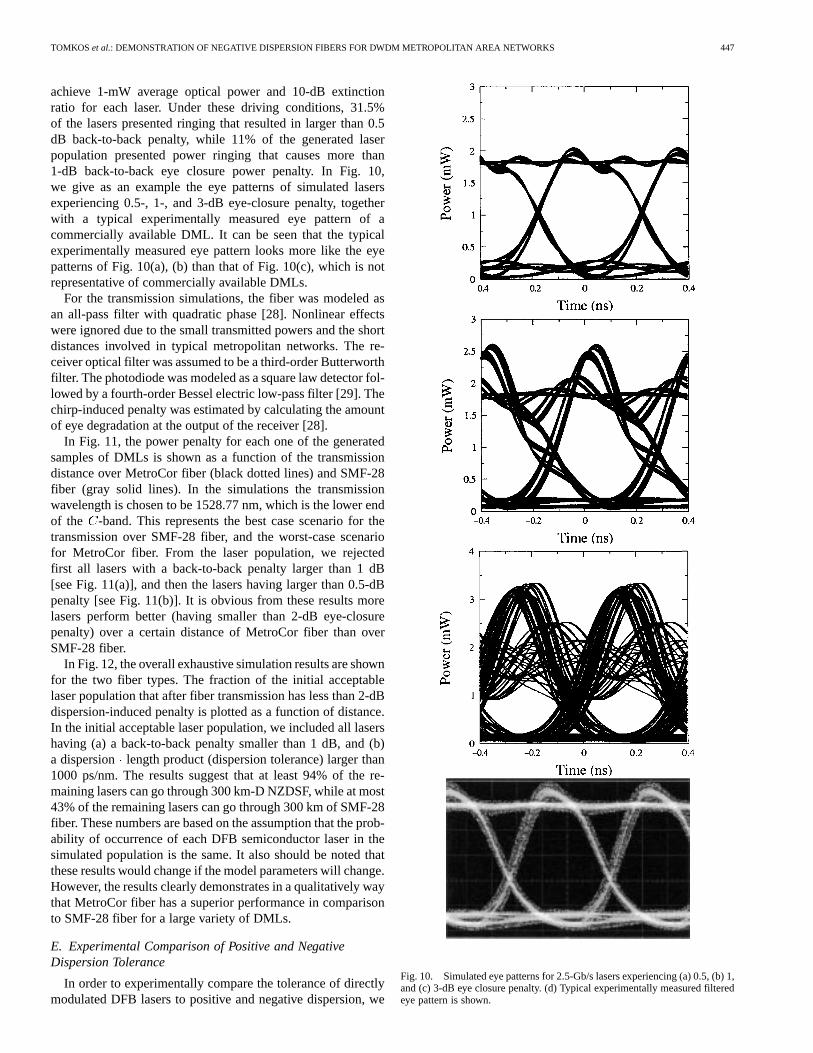
Fig. 23 shows BER measurement versus the received powermeasured using a preamplified receiver. The length of the PRBSwas 2 1. It is evident, that in the case of SMF-28 fiber, lowerror rates are achieved with higher power penalties at the max-imum link length than the penalties over the maximum linklength of MetroCor fiber. In fact, transmission of signals overa length of MetroCor fiber of up to 200 km is achieved withnegative power penalties. The maximum negative penalty wasabout 4.5 dB (at a BER of 10 ) for a distance of 125 km. This
Fig. 22. Measured 10-Gb/s eye patterns after (a) 0 km and (b) 225 km ofMetroCor fiber, and after (c) 0 km and (d) 90 km of SMF-28 fiber.
negative power penalty will provide a power margin that canbe used to relax the specifications on other optical devices in aMetro network. In the case of SMF-28 fiber, even at a distanceof 25 km, there is a power penalty larger than 2 dB at a BER of10 .
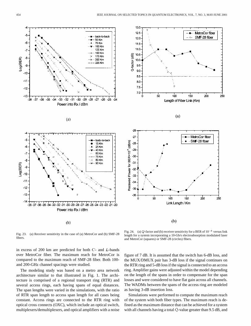
The system using SMF-28 fiber had a higher extinction ratioat the beginning of the link than the system using MetroCorfiber. That resulted in higher back-to-back-factor values andlower receiver sensitivity for the system using the SMF-28 fiber(Fig. 24). However, as the link length was increased a signifi-cant degradation in the achievable-factor was observed. The
-factor was dropped below the acceptable value ofdB for a link length of 90 km, while the receiver sensitivity fora BER of 10 increased about 7 dB to a value of28 dBm.The results for the MetroCor fiber show that the-factor canbe improved by almost 1 dB relative to the back-to-back case,while the receiver sensitivity is decreased by up to 3.5 dB. Theseresults indicate significant performance advantages when usingMetroCor fiber in 10-Gb/s applications involving distances ofup to 225 km.
IV. STUDY OF THE TRANSMISSION PERFORMANCE OF
EXTERNALLY MODULATED-MZ OVER METROCOR AND
SMF-28 FIBERS AT 10 Gb/s
In the future, it is expected that carriers may wish to upgradetheir metropolitan networks to 10-Gb/s bit rates, and use moredensely spaced channels across the- and -wavelengthbands. The need for elimination of dispersion compensationwill still be a requirement. The transmission distances inmetro area networks are much shorter than those in long-haulnetworks. Consequently, lower optical power levels can beused and the impact of optical nonlinearities is not expected tobe very significant (dispersion is still the limiting impairment).This section presents the results of a modeling study thatwas performed to verify that nonlinearities are not the mainlimitation for metropolitan area network applications at 10Gb/s and to predict the maximum uncompensated reach ofMetroCor fiber on a DWDM system. It will shown that reaches
454 IEEE JOURNAL ON SELECTED TOPICS IN QUANTUM ELECTRONICS, VOL. 7, NO. 3, MAY/JUNE 2001
Fig. 23. (a) Receiver sensitivity in the case of (a) MetroCor and (b) SMF-28fibers.
in excess of 200 km are predicted for both- and -bandsover MetroCor fiber. The maximum reach for MetroCor iscompared to the maximum reach of SMF-28 fiber. Both 100-and 200-GHz channel spacings were studied.
The modeling study was based on a metro area networkarchitecture similar to that illustrated in Fig. 1. The archi-tecture is comprised of a regional transport ring (RTR) andseveral access rings, each having spans of equal distances.The span lengths were varied in the simulations, with the ratioof RTR span length to access span length for all cases beingconstant. Access rings are connected to the RTR ring withoptical cross connects (OXC), which include an optical switch,multiplexers/demultiplexers, and optical amplifiers with a noise
Fig. 24. (a)Q-factor and (b) receiver sensitivity for a BER of 10versus linklength for a system incorporating a 10-Gb/s electroabsorption modulated laserand MetroCor (squares) or SMF-28 (circles) fibers.
figure of 7 dB. It is assumed that the switch has 6-dB loss, andthe MUX/DMUX pair has 3-dB loss if the signal continues onthe RTR ring and 5-dB loss if the signal is connected to an accessring. Amplifier gains were adjusted within the model dependingon the length of the spans in order to compensate for the spanlosses and were considered to have flat gain across all channels.The WADMs between the spans of the access ring are modeledas having 3-dB insertion loss.
Simulations were performed to compute the maximum reachof the system with both fiber types. The maximum reach is de-fined as the maximum distance that can be achieved for a systemwith all channels having a total-value greater than 9.5 dB, and

TOMKOS et al.: DEMONSTRATION OF NEGATIVE DISPERSION FIBERS FOR DWDM METROPOLITAN AREA NETWORKS 455
Fig. 25. Calculated maximum reach distances of (a) a 40-channel WDMsystem with 100-GHz channel spacing, and a (b) 20-channel WDM, with200-GHz channel spacing. Both fibers (MetroCor and SMF-28) are comparedacross theC- andL-bands for the cases of no- or optimum-modulator chirp.
an eye closure penalty due to distortion less than 3 dB. Fiberdispersion, fiber loss, modulator chirp, and nonlinearities werethe causes of the waveform distortion. The simulations wereperformed for the two EDFA bands, the conventional-bandwith channel wavelengths from 1530 to 1565 nm (frequenciesfrom 191.5 to 195.9 THz) and the long wavelength-band, withchannel wavelengths from 1570 to 1610 nm (frequencies from186.2 to 191.0 THz). Two channel plans were studied, (a) a40-channel WDM system with 100-GHz channel spacing, and(b) a 20-channel WDM with 200-GHz channel spacing. In bothchannel plans, the wavelengths were set according to the ITU-Tgrid. An external modulator (lithium niobate MZ type) was usedto modulate the optical signals at 10 Gb/s. The study was con-ducted for two chirp parameters of the modulator for each fibertype (0 and 0.7). The sign of the chirp parameter was set op-posite to the sign of the dispersion of the fiber in each case (op-timum chirp). An input power of 2-dBm per channel was chosenfor the simulations. The extinction ratio was 13 dB.
Fig. 25 shows bar charts of the maximum uncompensatedreach values for the two fibers, for the two-channel plans (100-and 200-GHz spacing), for both wavelength bands and for thecases of no- or optimum-modulator chirp. Adding modulatorchirp significantly increases maximum reach for all fibers inboth bands, with the benefit ranging from 24 km for SMF-28fiber to 74 km for MetroCor fiber, both in the-band. MetroCor
fiber outperformed SMF-28 fiber in both- and -bands witha reach of 206 km in the -band, and 264 km in the-bandin the case of 100-GHz spacing [seeFig. 25(a)]. In the case of200-GHz channel spacing [see Fig. 25(b)], the maximum reachin the -band is unaffected, while it is increased to 276 km in the
-band. For both chirp cases and for both channel spacings, thereach of SMF-28 fiber was less than half the reach of MetroCorfiber with the difference being larger in the-band. The verysmall change in the maximum transmission distance achievedwith MetroCor fiber when the channel spacing is reduced from200- to 100-GHz spacing indicates that the relative small ef-fective area of MetroCor fiber (about 46m at 1550 nm) incomparison with SMF-28 fiber (80m at 1550 nm) is not aconcern for Metropolitan area networks.
-factor profiles across the wavelength bands for all differentscenarios were also calculated. The overall results are shown inFig. 26. Included in each graph are the single channel-factorprofiles and -factor profile of the fully loaded WDM system.Degradation in single-channel is caused by waveform distor-tion due to fiber dispersion, fiber loss, modulator chirp, and self-phase modulation (SPM). In the multichannel case, cross-phasemodulation (XPM) and four-wave mixing (FWM) nonlineari-ties cause additional distortion.-factor profiles for MetroCorand SMF-28 fibers, with 100- and 200-GHz spacings and withor without modulator chirp are shown in Fig. 26. In the case ofMetroCor fiber, the maximum reach distance is limited by thereduced -factor values. Cross-channel nonlinearities (XPMand FWM) contribute to limiting the reach in the WDM system.At 100 GHz, their effects are more pronounced in comparisonto 200-GHz channel spacing. In the case of SMF-28 fiber, theeye-closure penalty due to dispersion is by far the largest hin-drance to maximum reach distance for SMF-28 fiber in both the
- and -bands. The -factor values shown in the figure arelarge, but the eye-closure penalty is 3 dB. Cross channel non-linearities degrade the-factor values by a small amount, espe-cially in the case of 100-GHz spacing. The slope of the-factorprofiles is different between the cases of SMF-28 and MetroCorfibers. The sign of the slope is the opposite, because the zerodispersion wavelength in the case of the SMF-28 fiber is at the“blue” side of the wavelength bands under investigation, whilein the case of MetroCor fiber is at the “red” side of the wave-length bands.
V. CONCLUSION
DWDM technologies make effective use of the availablefiber bandwidth and offer an added dimension to all-opticalnetworks. Recently, these technologies have been introducedto metropolitan area networks. The requirement that thesenetworks should be cost effective has added complexity tothe network engineering. The use of low-cost optical trans-mitters raises the dispersion-induced limitations to the mainimpairment that limits the size of metro networks. Dispersioncompensation techniques could be adopted as in the case oflong-haul networks, but the additional cost and the designcomplexity prohibit such a solution. An optical fiber especiallydesigned for Metro area applications that will take advantageof the characteristics of low cost transmitters and eliminate

456 IEEE JOURNAL ON SELECTED TOPICS IN QUANTUM ELECTRONICS, VOL. 7, NO. 3, MAY/JUNE 2001
Fig. 26. CalculatedQ-factor profiles across theC- andL-bands for (a) 100-GHz channel spacing with no modulator chirp, (b) 100-GHz channel spacingwith modulator chirp, (c) 200-GHz channel spacing with no modulator chirp, and (d) 200-GHz channel spacing, with modulator chirp. Squares correspond tosingle-channel transmission over SFM-28 fiber, triangles correspond to WDM transmission over SFM-28 fiber, diamonds correspond to single channeltransmissionover MetroCor fiber, and crosses correspond to WDM transmission over MetroCor fiber.
the need for dispersion compensation is highly desirable, andwill enable the introduction of DWDM technologies in themetro environment. This work provides a detailed study on thetransmission performance of such a novel nonzero dispersionshifted fiber with negative dispersion (MetroCor fiber). Theperformance of MetroCor fiber was studied using differenttypes of optical transmitters (DMLs, EA-DFBs, MZs). Thestudies were performed for both 1310- and 1550-nm wave-length windows at 2.5 and 10 Gb/s.
The improved performance of MetroCor fiber relative toa fiber with conventional dispersion characteristics (positivedispersion) is extensively discussed for the case of directlymodulated lasers having different chirp characteristics. Througha detailed understanding of the transmission characteristicsof transient or adiabatic chirp dominated lasers over fiberswith different dispersion characteristics, we show that theperformance of MetroCor fiber will always be superior incomparison with that of SMF-28 fiber. It has been shown that
DMLs with transient chirp dominated response give excellentperformance for 300 km of MetroCor fiber, where as suchDMLs are limited to about 100 km of SMF-28 fiber. DMLswith purely adiabatic chirp dominated response have almostthe same dispersion/length product performance for MetroCorand SMF-28 fiber. However, due to the lower absolute valueof dispersion, MetroCor fiber will achieve longer transmissiondistances than SMF-28 fiber. For practical transmitters, whereboth transient and adiabatic chirp exist, the performance ofnegative dispersion fibers (MetroCor fiber) in comparisonwith positive dispersion fibers, will always be superior. Inaddition, we show that at 10 Gb/s, where the transient chirpincreases, the improvement in the transmission performanceover MetroCor fiber relative to that over SMF-28 fiber willbe more pronounced than that at 2.5 Gb/s. All the theoreticalresults have been validated through experiments. Using a32-channel DWDM test bed, it was shown that MetroCor fiberexpands the system capabilities up to 300 km in the-band.

TOMKOS et al.: DEMONSTRATION OF NEGATIVE DISPERSION FIBERS FOR DWDM METROPOLITAN AREA NETWORKS 457
Fig. 27. Calculated power penalty versus transmission distance. Positivedispersion fiber and transient chirp only (curve 1), negative dispersion fiber andtransient chirp only (curve 4), both fiber types and adiabatic chirp only (curve3), positive dispersion fiber and both chirps (curve 2) and negative dispersionfiber and both chirps (curve 5).
Experimental and theoretical results for the case of transmis-sion of 10-Gb/s EA modulated signals over SMF-28 fiber andMetroCor fiber show that improved performance (in terms ofmaximum reach) is obtained using a negative dispersion fiber.This experimentally observed improvement in performance wasachieved when driving the EA-DFBs at voltage levels that re-sulted in high-power output from the device.
In the case of 10-Gb/s external modulated signals using MZmodulators, computer simulations predict that the maximumreach that can be accomplished with MetroCor fiber in the
-band without dispersion compensation is 206 km. In the-band the maximum distance predicted with MetroCor fiber
is 264 km for the case of 100-GHz channel spacing, and 276km for 200-GHz spacing. SMF-28 fiber performed signifi-cantly worse than MetroCor fiber. Adding modulator chirpsignificantly increased the maximum reach for both fibers.Increasing channel spacing resulted in very little or no increasein maximum reach.
In conclusion, we have shown that a NZDSF with negativedispersion (MetroCor fiber) is engineered to enhance opticalsystems resulting in reduced system costs and complexity, sincethe need of dispersion compensation is eliminated. MetroCorfiber takes advantage of the characteristics of inexpensive lasersand is expected to enable transparency in metro area optical net-works.
APPENDIX ASMALL -SIGNAL-BASED MODEL OF DMLS
This appendix presents a rigorous small-signal analysis ofthe interaction between laser chirp and chromatic dispersion.The target of this small-signal model is to analyze the impact oftransient and adiabatic chirp on the performance of fiber typeshaving different dispersion parameter signs. It is shown that theintersymbol interference (ISI) can be attributed to the phase dif-
ference between intensity and frequency modulations in the caseof transient chirp dominated lasers.
The instantaneous frequency change (chirp— ) is givenby the following expression:
(A.1)
whereinstantaneous optical power;linewidth enhancement factor;adiabatic chirp coefficient.
Taking the Laplace transform of (A.1), it can be shown thatthe small-signal FM response of a DML is given by the fol-lowing expression:
(A.1)
where is the angular modulation frequency and the av-erage optical power.
For the purpose of this study, a periodic small-signal si-nusoidal modulation of both intensity and phase is assumed.Therefore, the power of the optical signal at the output of theDFB semiconductor laser could be expressed as
(A.3)
where is the AM modulation index.The output complex envelope of the electric field could be
expressed as
(A.4)
In (A.4) is the frequency modulation (FM) index
(A.5)
is the phase difference between AM and FM
(A.6)
and is a frequency offset
(A.7)
The fiber transfer function is given by [27]:
(A.8)
where
(A.9)
is the phase change due to dispersion,is the carrier wave-length, is the dispersion parameter at is themodulation frequency, is the transmission distance andisthe speed of light in vacum.
The small-signal model has now been formulated. Asan example we will present the simulation results for thefollowing parameter set:

458 IEEE JOURNAL ON SELECTED TOPICS IN QUANTUM ELECTRONICS, VOL. 7, NO. 3, MAY/JUNE 2001
(separate chirp types) or
(combined chirp
types), mm, ps/nm/km and GHz(corresponding to Gb/s). The simulation results arepresented in Fig. 27. It can be seen that the power penaltyincreases dramatically for large transmission distances, ifwe transmit a waveform produced by a DML that has onlytransient chirp over positive dispersion fiber (curve 1). If thesame signal is transmitted over a negative dispersion fiber anegative power penalty is obtained (curve 4). For both fibertypes and for a DML that has only adiabatic chirp we obtainedthe same performance (curve 3). If a signal produced by aDML with both transient and adiabatic chirp is transmitted overa positive dispersion fiber we observe a penalty smaller thanthat in the case of transmission of signal with transient chirponly (curve 2). If the same signal is transmitted over negativedispersion fiber a further more negative power penalty willalso be achieved (curve 5). The results show that the transientchirp is deleterious for positive dispersion fibers and beneficialfor negative dispersion fibers. No performance improvementis observed if a negative dispersion fibers is used instead ofa positive dispersion fiber with the same absolute value ofdispersion in the exclusive presence of adiabatic chirp.
It is worth noting that the above small-signal analysis asso-ciates the phase difference between amplitude (AM) and fre-quency (FM) modulations, which is an intrinsic characteristic ofall lasers with the dispersion characteristics of the fiber withouteliminating either the transient or the adiabatic chirp terms. It isshown that when the AM phase lags compared to FM, the pulsesare compressed in a negative dispersion fiber. However, it shouldnoted that this analytical study is strictly valid for a small-signalsinusoidal waveform. The distortion-induced penalty in the caseof large-signal NRZ pulses must be studied using the rate equa-tions-based model.
REFERENCES
[1] A. A. M. Saleh and J. M. Simmons, “Architectural principles of opticalregional and metropolitan access networks,”J. Lightwave Technol., vol.17, pp. 2431–2448, Dec. 1999.
[2] N. Antoniades, A. Boskovic, J. K. Rhee, J. Downie, D. Pastel, I. Tomkos,I. Roudas, N. Madamopoulos, and M. Yadlowsky, “Engineering the per-formance of DWDM metro networks,” presented at the NFOEC’00,Denver, CO, Aug. 2000.
[3] C. A. Brackettet al., “A scalable multiwavelength multihop optical net-work: A proposal for research on all-optical networks,”J. LightwaveTechnol., vol. 11, pp. 736–753, May/June 1993.
[4] R. E. Wagneret al., “MONET: Multiwavelength optical networking,”J.Lightwave Technol., vol. 14, pp. 1349–1355, June 1996.
[5] S. B. Alexanderet al., “A precompetitive consortium on wide-band all-optical networks,”J. Lightwave Technol., vol. 17, pp. 2431–2448, Dec.1999.
[6] G. Agrawal and N. Dutta,Long Wavelength Semiconductor Lasers: VanNostrand Reinhold, 1986.
[7] G. P. Agrawal, Fiber Optic Communication Systems. New York:Wiley, 1992.
[8] P. J. Corvini and T. L. Koch, “Computer simulation of high bit rateoptical fiber transmission using single frequency lasers,”J. LightwaveTechnol., vol. LT-5, pp. 1591–1595, Nov. 1987.
[9] J. C. Cartledge and G. S. Burley, “The effect of laser chirping on light-wave system performance,”J. Lightwave Technol., vol. 7, pp. 568–573,Mar. 1989.
[10] C.-C. Wang, I. Roudas, I. Tomkos, M. Sharma, and R. S. Vodhanel,“Negative dispersion fibers for uncompensated metropolitan networks,”presented at the ECOC’00, Munich, Germany, Sept. 2000.
[11] J. C. Cartledge and B. Christensen, “Optimum operating points for elec-troabsorption modulators in 10 Gb/s transmission systems using nondis-persion shifted fiber,”J. Lightwave Technol., vol. 16, pp. 349–357, Mar.1998.
[12] G. Ishikawa, H. Ooi, K. Morito, K. Kamite, Y. Kotaki, and H. Nishimoto,“10 Gb/s optical transmission systems using modulator integrated DFBlasers with chirp optimizing,” inProc. ECOC’96, 1996, p. 245. paperWeP.09.
[13] K. Hinton and T. Stephens, “Modeling high-speed optical transmissionsystems,”IEEE J. Select. Areas Commun., vol. 11, pp. 380–392, Apr.1993.
[14] T. L. Koch and R. A. Linke, “Effect of nonlinear gain reduction on semi-conductor laser wavelength chirping,”Appl. Phys. Lett., vol. 48, pp.613–615, Mar. 1986.
[15] A. V. T. Cartaxo, “Small signal analysis for nonlinear and dispersiveoptical fibers and its application to design of dispersion supported trans-mission systems with optical dispersion compensation,” inIEE Proc.Part J—Optoelectonics, vol. 146, 1999, pp. 213–222.
[16] “Comparison of different DFB laser models within the European COST240 collaboration,” inIEE Proc.-Optoelectron., vol. 141, Apr. 1994, pp.82–88. COST 240 group.
[17] L. M. Zhang and J. E. Carrol, “Large signal dynamic model of the DFBlaser,”IEEE J. Quantum Electron., vol. 28, pp. 604–611, 1992.
[18] S. Hansmann, H. Burkhard, H. Walter, and H. Hillmer, “A tractablelarge signal dynamic model—Application to strongly coupled dis-tributed feedback lasers,”J. Lightwave Technol., vol. 12, pp. 952–956,1994.
[19] A. J. Lowery, “Transmission-line modeling of semiconductor lasers:The transmission-line laser model,”Int. J. Numer. Model, vol. 2, pp.249–265, 1990.
[20] L. Bjerkan, A. Royset, L. Hafskjaer, and D. Myhre, “Measurements oflaser parameters for simulation of high speed fiber-optic systems,”J.Lightwave Technol., vol. 14, pp. 839–850, May 1996.
[21] J. C. Cartledge and R. C. Srinisavan, “Extraction of DFB laser rate equa-tion parameters for system simulation purposes,”J. Lightwave Technol.,vol. 15, pp. 852–860, May 1997.
[22] K. Czotscher, S. Weisser, A. Leven, and J. Rosenzweig, “Intensity mod-ulation and chirp of 1,55�m multiple quantum well laser diodes: Mod-eling and experimental verification,”IEEE J. Select. Topics QuantumElectron., vol. 5, pp. 606–612, May/June 1999.
[23][24] R. A. Linke, “Modulation induced transient chirping in single frequency
lasers,” IEEE J. Quantum Electron., vol. QE-21, pp. 593–597, June1985.
[25] B. W. Hakki, “Evaluation of transmission characteristics of chirped DFBlasers in dispersive optical fiber,”J. Lightwave Technol., vol. 10, pp.964–970, July 1992.
[26] S. Mohrdiek, H. Burkland, F. Steinhagen, H. Hillmer, R. Losch, W.Schlapp, and R. Gobel, “10 Gb/s standard fiber transmission usingdirectly modulated 1.55 quantum-well DFB lasers,”IEEE Photon.Technol. Lett, vol. 7, pp. 1357–1359, Nov. 1995.
[27] O.-K. Kwon and J.-I. Shim, “The effects of longitudinal gain distribu-tions on the static and the dynamic properties in a�=4 phase-shiftedDFB laser,”IEEE J. Quantum Electron., vol. 34, pp. 225–232, Feb. 1998.
[28] A. F. Elrefaie, R. E. Wagner, D. Atlas, and D. G. Daut, “Chromaticdispersion limitations in coherent lightwave transmission systems,”J.Lightwave Technol., vol. LT-6, pp. 704–709, May 1988.
[29] Synch. Optical Network (SONET): Physical Layer Specifications, ANSIT1.105.06.
[30] Optical Interfaces for Equipments and Systems Relating to the Syn-chronous Digital Hierarchy, ITU Recommendation G. 957, July 1995.
Ioannis Tomkos received the B.Sc. degree in physics, the M.Sc. degree intelecommunications engineering from the University of Patras, Greece, andthe Ph.D. degree in optical telecommunications from the University of Athens,Athens, Greece, in 1994, 1996, and 2000, respectively.
He was with the Optical Communications Laboratory, University of Athens,Athens, Greece, as a Research Fellow, where he participated in several nationaland European research projects (e.g., ACTS, COST). He researched novel wave-length conversion technologies based on nonlinear effects in semiconductor op-tical amplifiers and fibers. He is currently with Corning, Inc., Somerset, NJ,where he is a Senior Research Scientist. His current research focuses in trans-port issues related with optical networks. He is currently leading efforts relatedwith transport performance and technology trends in metropolitan/regional areaoptical networks. He is author or co-author of about 50 papers.
Dr. Tomkos has received awards for his research accomplishments from TheInternational Society for Optical Engineers (SPIE), Bellingham, WA, and IEEE.

TOMKOS et al.: DEMONSTRATION OF NEGATIVE DISPERSION FIBERS FOR DWDM METROPOLITAN AREA NETWORKS 459
Dipak Chowdhury received the B.Sc. degree in electrical engineering fromBangladesh University of Engineering and Technology, Dhaka, Bangladesh, in1986, and the M.S. and Ph.D. degrees in electrical engineering from ClarksonUniversity, Potsdam, NY, in 1989 and 1991, respectively.
From 1991 to 1993, he had a joint appointment as a research associate atYale University, New Haven, CT, in the Applied physics department and atNew Mexico State University, Las Cruces, NM, in the Electrical EngineeringDepartment. For his graduate and post-graduate work he performed numericalmodeling of and experimentation on optical scattering from nonlinear micro-cavities. He joined Corning’s research and development facility, Somerset, NJ,in 1993. He focused his research effort in various aspects of optical commu-nication systems. Currently, he is managing modeling and simulation researchin fiber-optic communication systems and optical devices. His research inter-ests include linear and nonlinear devices, impairments in fiber-optic systemsand networks, e.g., nonlinearities, cross-talk, chromatic dispersion, and polar-ization-mode dispersion, and efficient algorithms for simulating fiber-optic sys-tems.
Jan Conradi received the B.Sc. degree in engineering physics from Queen’sUniversity, Kingston, ON Canada, the M.Sc. degree in solid state electronic en-gineering from the University of Birmingham, U.K., the Ph.D. degree in solidstate physics from Simon Fraser University, Burnaby, BC, Canada, in 1962,1964, and 1968, respectively.
He was with the RCA Labs, Montreal, Canada, where he developed Sil-icon avalanche photodetectors for early fiber-optic systems at 820 nm. He thenmoved to Bell Northern Research, Ottawa, Canada, (the Research and Develop-ment arm of Nortel Networks), where he managed various groups responsiblefor optical fiber development, fiber to the home systems, as well as two FTTHfield trials, and the company’s exploratory research for progressively higher bitrate fiber systems. He also had research projects on Mobile Radio, and Scanners& Printers. He was an industrial research chair professor at the research con-sortium TRLabs and the University of Alberta, In December 1997, he joinedCorning Inc., Somerset, NJ, as the first manager of external research, then ascore technology director, fiber communications, where he was responsible forleading the evolution of Corning Inc. research programs for the company’s nextgenerations of optical fiber. Currently, he is director of Strategy for Corning Op-tical Communications.
Dr. Conradi is a fellow of the Optical Society of America (OSA). He hasserved on numerous conference committees, including chairman of OFC,has been associate editor ofOptics Letters, the JOURNAL OF LIGHTWAVE
TECHNOLOGY, and IEEE PHOTONICSTECHNOLOGYLETTERS.
D. Culverhouse, was with the University of Southampton as a Senior ResearchFellow, where his research interests included nonlinear optics and switchingand fiber-based components. From 1997 to 1999, he joined Corning Inc. as aresearch scientist, where he worked within amplifier development. Currently,he is the Business Development Manager for Metropolitan Networks, wherehe acts as the technical lead when addressing optimized fiber designs and costeffective solutions for metropolitan-based architectures.
K. Ennser, photograph and biography not available at the time of publication.
Cynthia Giroux received the B.Sc. and M.E. degrees in metallurgy and mate-rials science from Carnegie-Mellon University, Pittsburgh, PA.
She is with Corning Incorporated, Somerset, NJ, where she manufactures op-tical fiber and components, as well as development of glass and coating pro-cesses for transmission fiber products. Most recently, she was leader of thecross-functional technical team, which investigated and developed negative dis-persion fiber (MetroCor fiber) for the metropolitan market.
Bradley S. Hallock received the B.S. degree in physics from State Universityof Cortland New York, in 1988.
He is currenlty with Corning Incorporated, Somerset, NJ, where he conductsphotonic measurement and fiber-optic systems research.
Timothy D. Kennedy, received the associates of science degree from the Uni-versity of Phoenix, Phoenix, AZ, in 1991.
From 1973 to 1995, he served in the United States Army, where he was theCommunications and Electronics Installation and Technical Evaluation Chief.In 1995, he was with AT&T. In 1996, he joined Lucent Technoligies as a SeniorTechnical Associate in the Advanced Technology Division. In 1997, he joinedCorning Incorporated at the Photonics research and Test Center, Somerset, NJ,as an optical fiber systems technologist. Recently, he has worked on dense wave-length-division-multiplexing systems experiments to support the commercial in-troduction of a negative dispersion fiber (MetroCor fiber) for the metropolitanmarket.
Ann Kruse received the B.S.E.E. and M.S.E.E. degree specializing in optics andelectromagnetics from the University of Missouri at Rolla, in 1992 and 1997,respectively, and the B.S.Ed. and M.S.Ed. degrees with majors in elementaryeducation and mathematics, and teaching of reading from Concordia Teacher’sCollege, Seward, NE and Northwest Missouri State University of Maryvillem,respectively.
While at UMR, she taught a laboratory class and a communications systemsclass. She then joined the network architecture team at WorldCom, Tulsa, Ok-lahoma, where she developed network availability models for both terrestrialand undersea networks, participated in standards activities, and participated invendor product evaluation. In 1999, she joined Corning, Inc., Photonic Research& Test Center in Somerset, NJ, where she is a Senior Scientist currently workingon modeling.
S. Kumar, photograph and biography not available at the time of publication.
N. Lascar, photograph and biography not available at the time of publication.
Ioannis Roudas was born in 1966 in Athens,Greece. He received the diploma in Physics and theCertificate in electronics and radio-engineering fromthe University of Athens, Greece, and the M.S. andPh.D. degrees from Ecole Nationale Supérieure desTélécommunications (ENST) Paris, Paris, France, in1988, 1990, 1991, and 1995, respectively. His Ph.D.thesis concerned modeling and optimal design ofcoherent optical communication systems.
From 1995 to 1998, he was with the Optical Net-working Research Department at Bell Communica-
tions Research, Red Bank, NJ, where he was involved in the multiwavelengthoptical networking (MONET) project. His research mainly focused on the devel-opment of an efficient computer representation of the MONET optical transportlayer. He was also an Adjunct Professor in Electrical Engineering at ColumbiaUniversity during the fall semesters 1997 and 1998. Since 1999, he is a SeniorResearch Scientist in the Photonic Research and Test Center of Corning Inc.,Somerset, NJ. His current research concerns modeling of transmission effectsin high data rate optical communications systems and networks.
Dr. Roudas serves as a reviewer for the IEEE Optical Society of America(OSA) JOURNAL OF LIGHTWAVE TECHNOLOGY and the IEEE PHOTONICS
TECHNOLOGY LETTERS.

460 IEEE JOURNAL ON SELECTED TOPICS IN QUANTUM ELECTRONICS, VOL. 7, NO. 3, MAY/JUNE 2001
Manish Sharma received the M.Eng. degree in electrical and electronic en-gineering from the University College London, London, U.K., and the Ph.D.degree from Sophia University, Tokyo, Japan, in 1990 and 1998, respectively.
From 1990 to 1998, he was engaged in the reseach and development of opticalcommunication systems and networks at Toshiba Corporation, Tokyo, Japan.In 1998, he joined Corning Incorporated as a Senior Research Scientist at thePhotonic Research and Test Center. His research interests include dense wave-length-division-multiplexing (DWDM) optical networking systems and compo-nents.
R. S. Vodhanelreceived the B.S., M.S., and Ph.D. degrees in physics from theUniversity of California, Irvine, CA, in 1974, and from the University of Illinois,Urbana-Champaign, IL, in 1976 and 1980, respectively.
From 1980 to 1984, he conducted research in the single-mode fibertransmission systems at AT&T Laboratories. In 1984, he joined Bellcore,where his research concerned coherent optical communications systems, densewavelength–division-multiplexing (DWDM) transmission in metropolitan,and long-haul networks as part of the Multiwavelength Optical Networking(MONET) Consortium. In 1997, he joined Tellium Inc. as a founding member,where he developed optical transmission products for metropolitan andlong-haul markets. Since 1999, he has been a Research Manager with CorningInc., Photonics Research and Test Center, Somerset, NJ. His current researchinterests include DWDM transmission on novel optical fibers.
C.-C. Wang, photograph and biography not available at the time of publication.