
Demonstration of Bridge Project Delivery Using BIM - Federal ...
129
Demonstration of Bridge Project Delivery Using BIM Office of Infrastructure FHWA-HIF-21-031 March 2021
-
Upload
khangminh22 -
Category
Documents
-
view
3 -
download
0
Transcript of Demonstration of Bridge Project Delivery Using BIM - Federal ...
Demonstration of Bridge Project Delivery Using BIM
Office of Infrastructure FHWA-HIF-21-031
March 2021

FOREWORD
The Federal Highway Administration conducted research to implement the use of Building Information Modeling for the design and fabrication of highway bridges. The research used the Industry Foundation Class (IFC) Bridge Design to Construction Information Exchange (U.S.) exchange specification and conducted a case study of the digital delivery of a bridge project in Utah. The objective was to develop information about using the IFC standard for the digital delivery of bridge projects in the U.S. Digital delivery refers to the use of digital processes and media to design, procure, construct, fabricate, operate, and maintain infrastructure assets. This research may interest State transportation agencies because of the growing interest and investment in the digital delivery of bridges in the United States.
Joseph L. Hartmann, Ph.D., P.E., Director, Office of Bridges and Structures
Notice
This document is disseminated under the sponsorship of the U.S. Department of Transportation (USDOT) in the interest of information exchange. The U.S. Government assumes no liability for the use of the information contained in this document.
The U.S. Government does not endorse products or manufacturers. Trademarks or manufacturers’ names appear in this report only because they are considered essential to the objective of the document. They are included for informational purposes only and are not intended to reflect a preference, approval, or endorsement of any one product or entity.
Non-Binding Contents
The contents of this document do not have the force and effect of law and are not meant to bind the public in any way. This document is intended only to provide clarity to the public regarding existing requirements under the law or agency policies.
Quality Assurance Statement
The Federal Highway Administration (FHWA) provides high-quality information to serve Government, industry, and the public in a manner that promotes public understanding. Standards and policies are used to ensure and maximize the quality, objectivity, utility, and integrity of its information. FHWA periodically reviews quality issues and adjusts its programs and processes to ensure continuous quality improvement.

TECHNICAL REPORT DOCUMENTATION PAGE
1. Report No.FHWA-HIF-20-031
2. Government Accession No.N/A
3 Recipient Catalog No. N/A
4. Title and SubtitleDemonstration of Bridge Project Delivery Using BIM
5. Report DateSeptember 20206. Performing Organization CodeN/A
7. Author(s)Joseph M. Brenner, Francesca Maier, Tim Chipman, Kelley C. Severns,Roger Grant
8. Performing Organization Report No.N/A
9. Performing Organization Name and AddressWSP USA, Inc.1015 Half St. SE, Suite 650Washington, DC 20003
10. Work Unit No. (TRAIS)N/A
11. Contract or Grant No.DTFH6114D00048
12. Sponsoring Agency Name and AddressFederal Highway AdministrationOffice of Infrastructure Bridges and Structures1200 New Jersey Avenue, SEWashington, DC 20590
13. Type of Report and Period CoveredDraft Final Report
14. Sponsoring Agency CodeN/A
15. Supplementary NotesFHWA Technical Manager: Brian M. Kozy, HIBS-10.16. AbstractThe application of Building Information Modeling (BIM) to infrastructure is growing in prominence nationally andinternationally. BIM is one tool involved in the emerging trend to deliver infrastructure projects using digital media, apractice known as digital delivery. With digital delivery, the digital data created at one point in the asset lifecycle isused at a later point without the need to re-create it. Bridge owners are interested in scaling the benefits of digitaldelivery across the agency’s bridge design and construction program.
This research addresses two specific challenges to digital delivery: technical needs to manage the new, digital processes and media, and standardizing the content and format of the digital exchanges. There are three discrete products of this research included in this report: • A case study of a bridge project delivered digitally using BIM-based media for the contract documents.• Information for contracting professionals who need to incorporate BIM into contracts and specifications.• A utility that implements the Industry Foundation Class (IFC) Bridge Design to Construction Information
Exchange (U.S.) exchange specification to convert AASHTOWare Bridge Design data into 3D bridge models.
The products of this research build upon previous efforts and supports ongoing industry research on multiple fronts to further implement digital delivery in bridge design, construction, fabrication, and asset management.
17. Key wordsBIM for Bridges, Building Information Modeling, DigitalDelivery, Data Standard, Industry Foundation Classes
18. Distribution StatementNo restrictions. This document is available to the publicthrough the National Technical Information Service,Springfield, VA 22161.
http://www.ntis.gov19. Security Classif. (of this report)Unclassified
20. Security Classif. (of this page)Unclassified
21. No. of Pages115
22. Price
Form DOT F 1700.7 (8-72) Reproduction of completed page authorized.
ii

iii
ACKNOWLEDGMENTS
This report represents the results of research conducted by the authors and does not necessarily represent the views or policies of the State transportation departments, consultants, construction contractors or fabricators whose policies and practices have been referenced.
This project is possible due to the funding from the Federal Highway Administration (FHWA) and the assistance of the Alaska, Wisconsin and Utah Departments of Transportation, as well as the consultants, construction contractors, and fabricators involved in the studied construction project. The contribution of the following individuals is also acknowledged:
Utah Department of Transportation (UDOT): the authors acknowledge the assistance of the individuals involved in delivering UDOT’s digital delivery through model-based design and construction initiative and the individuals involved in the studied project.
• Carmen Swanwick• Cheryl Hersh• Sam Newton• Becky Hjelm• Michelle Page• George Lukes
Wisconsin Department of Transportation (Wisconsin DOT) and Alaska Department of Transportation & Public Facilities (Alaska DOT&PF): the authors acknowledge the assistance of the Wisconsin DOT and the Alaska DOT&PF that provided access to AASHTOWare files from their bridge inventory to test the AASHTOWare BrD to Industry Foundation Class (IFC) exchange utility. Additionally, the authors would like to acknowledge the assistance of Danielle DeTennis from the Wisconsin DOT in testing the AASHTOWare BrD to IFC exchange utility.
The original maps on pages 9 and 14 are the copyright property of Google® Earth™ and can be accessed from https://www.google.com/earth.
FHWA is the source of all figures and photographs within this document unless noted otherwise.
iv
TABLE OF CONTENTS
CHAPTER 1 BACKGROUND ............................................................................................ .. 1
Foundational Work ................................................................................................................... 1 Related Ongoing Work ............................................................................................................. 3 Objectives .................................................................................................................................. 3 Limitations of BIM ................................................................................................................... 4
BIM Sophistication ............................................................................................................. 5 BIM Maturity and Digital Delivery .................................................................................... 6
CHAPTER 2 CASE STUDY .................................................................................................... 9
Introduction ............................................................................................................................... 9 Digital Delivery Goals ............................................................................................................. 10 Project Characteristics ........................................................................................................... 10
Scope of Work .................................................................................................................. 11 Procurement Model ........................................................................................................... 11 Site Conditions .................................................................................................................. 12 Existing Bridges ................................................................................................................ 13 Proposed Bridges .............................................................................................................. 15 Partnering .......................................................................................................................... 19
BIM Processes ......................................................................................................................... 20 Software Evaluation and Selection ................................................................................... 20 Project Execution Planning ............................................................................................... 21 BIM Goals and Uses ......................................................................................................... 22 Roles and Responsibilities ................................................................................................ 22 Collaboration Framework ................................................................................................. 23 Information Management.................................................................................................. 23 Information Exchanges ..................................................................................................... 24 Contract Documents.......................................................................................................... 26
Using BIM on the Project ....................................................................................................... 26 Model Authoring ............................................................................................................... 26 Design Review .................................................................................................................. 28 Quality Control ................................................................................................................. 29 Shop Drawings .................................................................................................................. 29 Steel Fabrication ............................................................................................................... 29 Prestressed Concrete Girder Fabrication .......................................................................... 30 Reinforcement Bar Fabrication ......................................................................................... 32 Construction ...................................................................................................................... 33 Construction Administration ............................................................................................. 35 Federal Oversight .............................................................................................................. 36 Handover Information ....................................................................................................... 36
v
Conclusion ............................................................................................................................... 36 Limitations ........................................................................................................................ 36 Opportunities..................................................................................................................... 38 Next Steps ......................................................................................................................... 38
CHAPTER 3 BIM SUPPORTING REFERENCES ............................................................ 40 CADD/BIM Manuals .............................................................................................................. 40
Digital Signatures and Seals ............................................................................................. 40 Bridge Design Manual ............................................................................................................ 41 BIM/CADD Workspace and Template Files ........................................................................ 41 LOD Specification ................................................................................................................... 42 Project Execution Plan ........................................................................................................... 44 Classification System .............................................................................................................. 45 Model Inventories or Model Progression Specifications ..................................................... 45 Model View Definition ............................................................................................................ 46 Geospatial Distance Distortions ............................................................................................. 48
CHAPTER 4 BIM TECHNICAL SPECIFICATIONS FOR BRIDGES ........................... 49 Introduction ............................................................................................................................. 49 Technical Specifications for BIM-Based Design .................................................................. 49
Determining BIM-Related Roles and Responsibilities ..................................................... 49 BIM Products .................................................................................................................... 51
Construction Specifications ................................................................................................... 52 Partnering in BIM Projects ............................................................................................... 52 Electronic Documents and Digital Signatures .................................................................. 53 Scope Validation ............................................................................................................... 53 Exchange of Information and Communication ................................................................. 53 Construction Simulations .................................................................................................. 55
CHAPTER 5 AASHTOWARE BRD TO IFC EXCHANGE UTILITY ........................... 56
Introduction ............................................................................................................................. 56 Data Models ............................................................................................................................. 56
AASHTOWare Bridge Data Model .................................................................................. 56 IFC Data Model ................................................................................................................ 57
Sample Bridges ........................................................................................................................ 62 Steel Girder Bridge ........................................................................................................... 62 Concrete Box Girder Bridge ............................................................................................. 63 Precast Channel Girder Bridge ......................................................................................... 64 Bascule Bridge .................................................................................................................. 64 Splice Example ................................................................................................................. 65 Pier with Multiple Columns .............................................................................................. 66 Box Culvert ....................................................................................................................... 66
vi
Steel Truss ......................................................................................................................... 67 Software Architecture ............................................................................................................ 68
Dependencies .................................................................................................................... 68 API—IFC Conversion ...................................................................................................... 69 API—Bridge Data Model ................................................................................................. 70
Findings and Conclusions ...................................................................................................... 71 AASHTOWare Software .................................................................................................. 71 Bridge API ........................................................................................................................ 71 Data Needs ........................................................................................................................ 72 Data Exporting for Construction ....................................................................................... 72 Data Importing for Structural Analysis............................................................................. 73
Summary .................................................................................................................................. 73 CHAPTER 6 IFC MODEL OF CASE STUDY BRIDGES ................................................. 74 Introduction ............................................................................................................................. 74 Current Digital Models .......................................................................................................... 74
IFC Export ........................................................................................................................ 74 COLLADA™ Export ........................................................................................................ 75
Proposed Digital Models ........................................................................................................ 75 Structure Elements ................................................................................................................. 76
Deck .................................................................................................................................. 77 Steel Girders...................................................................................................................... 78 Precast Concrete Girders................................................................................................... 80 Cross Frames ..................................................................................................................... 80 Bearings ............................................................................................................................ 81 Abutments ......................................................................................................................... 82 Piers................................................................................................................................... 84 Parapets ............................................................................................................................. 85 Terrain ............................................................................................................................... 86
Digital Exchanges .................................................................................................................... 86 Bridge Horizontal and Vertical Geometry ........................................................................ 87 Bridge Structural Analysis ................................................................................................ 88 Contract Drawing Representation ..................................................................................... 90 Fabrication Details, Shop Drawings, and Processes ......................................................... 94 Quantity Takeoff ............................................................................................................... 99 Visualization ..................................................................................................................... 99 Clash Identification ......................................................................................................... 100 As-built Drawings ........................................................................................................... 100
Key Findings and Gap Analysis .......................................................................................... 100 Use Cases ........................................................................................................................ 101

vii
Automated Refinement ................................................................................................... 101 Schema Developments Needed ....................................................................................... 102
CHAPTER 7 KEY FINDINGS AND SUGGESTIONS ..................................................... 103 Using Digital Delivery Today ............................................................................................... 103 Using IFC with State Bridge Inventories ............................................................................ 104 Using IFC for Bridge Construction and Fabrication ........................................................ 104 BIM Object template ............................................................................................................ 105
Template Introduction ..................................................................................................... 105 Template Structure .......................................................................................................... 106 BIM Object Template and National BIM Library .......................................................... 110
Conclusion ............................................................................................................................. 110
CHAPTER 8 REFERENCES .............................................................................................. 111
viii
LIST OF FIGURES
Figure 1: Timeline. Bridge data standardization activities. ............................................................ 3 Figure 2: Flowchart. Examples of the 12 levels of BIM................................................................. 6 Figure 3: Illustration. Digital migration from 2D plans to digital information. ............................. 7 Figure 4: Flowchart. Digital construction information flow. .......................................................... 7 Figure 5: Map. Project location. ..................................................................................................... 9 Figure 6: Flowchart. UDOT's intended BIM production process. ................................................ 10 Figure 7: Photograph. Aerial view of the Tooele Interchange and the SR-36 bridge. ................. 13 Figure 8: Photograph. Aerial view of the Blackrock Interchange and the I-80 bridges. .............. 13 Figure 9: Photograph. I-80 bridges from the UPRR looking west in March 2017. ...................... 14 Figure 10: Photograph. I-80 WBL over UPRR looking south in March 2017. ............................ 14 Figure 11: Photograph. SR-36 over I-80 EBL and WBL looking east in April 2018. ................. 15 Figure 12: Photograph. The new SR-36 bridge (left) alongside the existing SR-36 bridge (right). ........................................................................................................................................... 16 Figure 13: Schematic. Plan view of the selected alternative for the I-80 bridges. ....................... 17 Figure 14: Schematic. Plan view of the selected alternative for the SR-36 bridge. ..................... 18 Figure 15: Photograph A model coordination meeting in the project office. ............................... 19 Figure 16: Flowchart. Steps taken to initiate the BIM process. .................................................... 20 Figure 17: Illustration. Bridge model viewed in authoring (left) and receiving (right) software. ........................................................................................................................................ 24 Figure 18: Flowchart. Model authoring process. .......................................................................... 27 Figure 19: Photo. Fabricated steel plate girders for the I-80 bridges in the fabrication yard. ...... 30 Figure 20: Photo. The new SR-36 girders were fabricated to accommodate complex geometry. ...................................................................................................................................... 31 Figure 21: Photo. Harris Rebar uses digital processes for fabricating and tagging bars. ............. 33 Figure 22: Photo. The SR-36 bridge under construction in June 2019. ........................................ 35 Figure 23: Illustration. Three levels of development for a prestressed beam. .............................. 42 Figure 24: Illustration. A model inventory for a proposed bridge. ............................................... 46 Figure 25: Diagram. AASHTOWare BrD data model. ................................................................. 57 Figure 26: Diagram. IFC data model. ........................................................................................... 57 Figure 27: Diagram. IFC data structures for bridge systems. ....................................................... 58 Figure 28: Diagram. IFC data structures for bridge superstructure. ............................................. 59 Figure 29: Diagram. IFC data structures for bridge geometry. ..................................................... 60 Figure 30: Graphic. IFC attributes that match AASHTOWare parameters for steel I-shape. ...... 60 Figure 31: Graphic. A prestressed tee template described in IFC with freeform geometry. ........ 61 Figure 32: Photo. Comparison of two representations for solid geometry. .................................. 61 Figure 33: Illustration. Digital rendering of steel girder bridge. ................................................... 62 Figure 34: Illustration. Three digital renderings of multi cell box girder bridge. ......................... 63 Figure 35: Illustration. Digital rendering of precast channel bridge. ............................................ 64
ix
Figure 36: Illustration. Digital rendering of bascule bridge. ........................................................ 65 Figure 37: Illustration. Digital rendering of splice example. ........................................................ 65 Figure 38: Illustration. Digital rendering of pier with multiple columns. .................................... 66 Figure 39: Illustration. Digital rendering of culvert...................................................................... 67 Figure 40: Illustration. Digital rendering of truss bridge. ............................................................. 67 Figure 41: Diagram. Software module dependencies as integrated with utility application. ....... 68 Figure 42: Diagram. Software module dependencies as integrated with BrD. ............................. 69 Figure 43: Illustration. IFC export with tessellated geometry. ..................................................... 74 Figure 44: Illustration. COLLADA™ export as viewed in Autodesk® Revit. ............................. 75 Figure 45: Illustration. Steel bridge models (C1047). .................................................................. 77 Figure 46: Illustration. Precast bridge model (F881). ................................................................... 77 Figure 47: Illustration. Deck from steel bridge. ............................................................................ 78 Figure 48: Illustration. Steel plate girder elements. ...................................................................... 78 Figure 49: Photo. Fabricated steel plate girders for the I-80 bridges. ........................................... 79 Figure 50: Illustration. Precast concrete girder. ............................................................................ 80 Figure 51: Illustration. Cross frame element. ............................................................................... 81 Figure 52: Illustration. Bearing element. ...................................................................................... 82 Figure 53: Illustration. Abutment from steel bridge. .................................................................... 82 Figure 54: Illustration. Abutment from precast bridge. ................................................................ 83 Figure 55: Photo. Constructed abutment on SR 36 bridge. .......................................................... 83 Figure 56: Illustration. Pier from precast concrete bridge. ........................................................... 84 Figure 57: Photo. Constructed pier from precast concrete bridge. ............................................... 84 Figure 58: Illustration. Parapet element. ....................................................................................... 85 Figure 59: Photo. Parapet form next to parapet. ........................................................................... 85 Figure 60: Illustration. Terrain mesh from steel bridge site. ........................................................ 86 Figure 61: Graph. Representation of vertical profile as viewed in TUM OpenInfra Platform......................................................................................................................................... 87 Figure 62: Illustration. Structural analysis model for superstructure of the precast bridge. ......... 88 Figure 63: Illustration. Steel cross frame with dimensions and other annotations generated from IFC........................................................................................................................................ 91 Figure 64: Illustration. Parapet reinforcement and utility ducts. .................................................. 92 Figure 65: Illustration. Reinforcement bar shape as captured in IFC. .......................................... 93 Figure 66: Illustration. Example of steel plate exported to DSTV file. ........................................ 94 Figure 67: Illustration. Precast deck panel element. ..................................................................... 97 Figure 68: Illustration. Precast panel repetition shown in one girder bay. ................................... 97 Figure 69: Illustration. Resulting IFC import of deck panel into Tekla® Structures. ................... 98 Figure 70: Illustration. Imported IFC data represented in drawings in Tekla® Structures. .......... 98 Figure 71: Illustration. Bridge elements visualization as viewed in DDS CAD Viewer. ............. 99 Figure 72: Illustration. Sample BIM object description and field name parameters for a cross frame. ................................................................................................................................. 110
x
LIST OF TABLES
Table 1: Parties involved in delivering the Blackrock project ...................................................... 12 Table 2: Federated model software products evaluated on behalf of UDOT. .............................. 20 Table 3: Software selected for use on the Blackrock project........................................................ 21 Table 4: Level of development descriptions ................................................................................. 23 Table 5: Element grade descriptions. ............................................................................................ 24 Table 6: Level of development descriptions. ................................................................................ 43 Table 7: Software modules ........................................................................................................... 69 Table 8: Selection of IFC data mapping for structural analysis model......................................... 88 Table 9: Steel girder material properties captured in IFC ............................................................. 91 Table 10: IFC data mapping for reinforcement schedules. ........................................................... 92 Table 11: Example of deck quantities computed from geometry in IFC model ........................... 99 Table 12: BIM object description and instance parameters for the cross frame above. ............. 109
xi
LIST OF COMMONLY USED ACRONYMS
2D two-dimensional 3D three-dimensional 4D four-dimensional, i.e. three physical dimensions plus time 5D five-dimensional, i.e. three physical dimensions plus time and cost AASHTO American Association of State Highway and Transportation Officials AIA American Institute of Architects AISC American Institute of Steel Construction Alaska DOT&PF Alaska Department of Transportation and Public Facilities API Application Programming Interface BIM Building Information Modeling bSI buildingSmart International BrD Bridge Design, from AASHTOWare Bridge Design software BrR Bridge Rating, from AASHTOWare Bridge Design software CAD computer-aided drafting CADD computer-aided design and drafting CM construction manager CM/GC construction manager/general contractor COLLADA™ A portmanteau of COLLAborative Design Activity DGN A name of a Bentley® design file format EBL eastbound lanes FHWA Federal Highway Administration IDM Information Delivery Manual I Interstate ISO International Organization for Standardization IFC Industry Foundation Classes LOD Level of Development MBDC Model-based Design and Construction MPS Model Progression Specification MVD Model View Definition NBI National Bridge Inventory PAS Publicly Available Specification PDF Portable Document Format
xii
PxP Project Execution Plan QC quality control SR State Route TPF Transportation Pooled Fund UDOT Utah Department of Transportation UPRR Union Pacific Railroad U.S. United States WBL westbound lanes Wisconsin DOT Wisconsin Department of Transportation XML eXtensible Markup Language

1
CHAPTER 1 BACKGROUND
The United States (U.S.) bridge industry has pursued bridge data standards for over a decade without consensus.(1) Building Information Modeling (BIM) is a process to develop and use a digital representation of the physical and functional characteristics(2) of an object in its design, construction, maintenance, and operation. BIM began being used for vertical construction in the early 2000s. By the late 2000s, practice standards for vertical construction began to emerge and BIM use grew both in frequency and sophistication, with noted efficiencies.(2)
BIM has matured in the architecture and buildings domain and enjoyed widespread adoption in the years following a series of major standardization milestones.(3) Data standards for buildings are centered on the Industry Foundation Classes (IFC) data schema and exchange file format. IFC was adopted as non-binding and voluntary International Organization for Standardization (ISO) Publicly Available Specification (PAS) in 2005 and an International Standard in 2013.(4) Interoperability of BIM data enabled multidisciplinary collaboration, which brought notable efficiencies through visualization, spatial coordination, enhanced analysis, and the avoidance of conflicts in construction.(3)(5)
The ability to share digital data sooner in the design-construction process created the opportunity to accelerate projects and reduce effort spent eliminating and avoiding conflict between disciplines.(5) As a result, non-binding and voluntary standards emerged to manage collaboration through project execution planning.(2) The opportunity for interdisciplinary collaboration created a need to alter the make-up of deliverables to include electronic data exchanges. In 2008, the American Institute of Architects (AIA) developed a non-binding and voluntary standard contract addendum, E202,(6) which was followed in 2015 by a non-binding and voluntary standard contract addendum developed by a broad coalition of architecture, engineering, and construction organizations, called ConsensusDocs.(7) Both have been refreshed after years of use.
The persistent lack of data standards for horizontal assets limits the application of BIM to transportation in general and bridges in particular. A number of emerging design and construction technologies depend on digital bridge information created with BIM. Using BIM may enable the delivery of bridge information using digital media, known as digital delivery, and could create efficiencies in bridge project delivery. This research supports progress toward expanded use of BIM in bridge design, construction, and fabrication.
Foundational Work
Initial research into bridge data standards considered using an eXtensible Markup Language (XML) schema as part of a wider effort to close gaps in transportation data exchange schemas.(1) The American Association of State Highway and Transportation Officials’ (AASHTO) then Subcommittee on Bridges and Structures adopted a resolution titled Comprehensive Integrated Bridge Project Delivery through Automation, which recognized the need for data standardization in the bridge industry.(8) At the time, the family of XML schemas, known as TransXML, was the most promising approach. Around the same time, however, an international group began exploring the use of IFC for bridges.(9)
2
The TransXML project was intended to emerge in two phases: first, create a standard stewardship organization, and second, develop the schemas.(1) While the schemas were developed, limited outreach meant that few State transportation departments were aware of their existence.(10) By the time that there was renewed focus on the need for digital delivery for bridges, the IFC-Bridge project had gained enough momentum that there was doubt over the viability of TransXML. An implementation roadmap developed in 2013 laid a similar framework for moving forward with data standards—either XML-based or IFC-based—but relied on an emerging governance body that failed to emerge.(8)
Nevertheless, part of that study involved creating the first Model View Definition (MVD) for concrete and steel workhorse bridges. An MVD is the subset of a data schema that can describe a specific information exchange. An Information Delivery Manual (IDM) may be mapped to different data schemas; the initial study mapped the concrete and steel workhorse bridge IDM to three: IFC, Geography Markup Language, and a community-driven XML-based schema called OpenBrIM.(8)
Subsequent work focused on the design-to-construction information exchange and created an MVD that adequately captured the information used for the construction of a steel and a concrete workhorse bridge. The resulting Industry Foundation Class (IFC) Bridge Design to Construction Information Exchange (U.S.) is an MVD that expresses the bridge information necessary for construction in IFC version 4.1.(11)
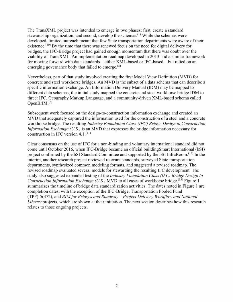
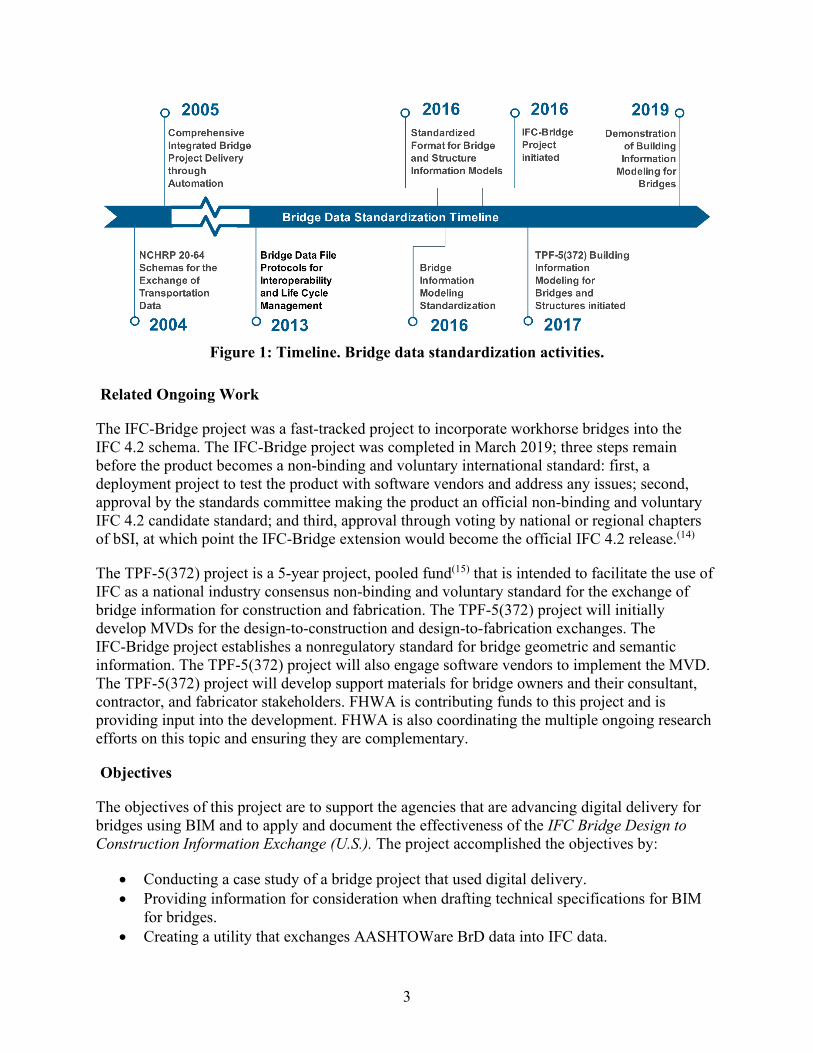
Clear consensus on the use of IFC for a non-binding and voluntary international standard did not come until October 2016, when IFC-Bridge became an official buildingSmart International (bSI) project confirmed by the bSI Standard Committee and supported by the bSI InfraRoom.(12) In the interim, another research project reviewed relevant standards, surveyed State transportation departments, synthesized common modeling formats, and suggested a revised roadmap. The revised roadmap evaluated several models for stewarding the resulting IFC development. The study also suggested expanded testing of the Industry Foundation Class (IFC) Bridge Design to Construction Information Exchange (U.S.) MVD to all cases of workhorse bridge.(13) Figure 1 summarizes the timeline of bridge data standardization activities. The dates noted in Figure 1 are completion dates, with the exception of the IFC-Bridge, Transportation Pooled Fund (TPF)-5(372), and BIM for Bridges and Roadway – Project Delivery Workflow and National Library projects, which are shown at their initiation. The next section describes how this research relates to those ongoing projects.
3
Figure 1: Timeline. Bridge data standardization activities.
Related Ongoing Work
The IFC-Bridge project was a fast-tracked project to incorporate workhorse bridges into the IFC 4.2 schema. The IFC-Bridge project was completed in March 2019; three steps remain before the product becomes a non-binding and voluntary international standard: first, a deployment project to test the product with software vendors and address any issues; second, approval by the standards committee making the product an official non-binding and voluntary IFC 4.2 candidate standard; and third, approval through voting by national or regional chapters of bSI, at which point the IFC-Bridge extension would become the official IFC 4.2 release.(14)
The TPF-5(372) project is a 5-year project, pooled fund(15) that is intended to facilitate the use of IFC as a national industry consensus non-binding and voluntary standard for the exchange of bridge information for construction and fabrication. The TPF-5(372) project will initially develop MVDs for the design-to-construction and design-to-fabrication exchanges. The IFC-Bridge project establishes a nonregulatory standard for bridge geometric and semantic information. The TPF-5(372) project will also engage software vendors to implement the MVD. The TPF-5(372) project will develop support materials for bridge owners and their consultant, contractor, and fabricator stakeholders. FHWA is contributing funds to this project and is providing input into the development. FHWA is also coordinating the multiple ongoing research efforts on this topic and ensuring they are complementary.
Objectives
The objectives of this project are to support the agencies that are advancing digital delivery for bridges using BIM and to apply and document the effectiveness of the IFC Bridge Design to Construction Information Exchange (U.S.). The project accomplished the objectives by:
• Conducting a case study of a bridge project that used digital delivery. • Providing information for consideration when drafting technical specifications for BIM
for bridges. • Creating a utility that exchanges AASHTOWare BrD data into IFC data.
4
• Converting a library of bridges to IFC and viewing the bridges in viewer software. • Creating an IFC model of the case study bridges. • Developing a BIM object template framework for extensions to the standards.
Limitations of BIM
There are both aspirations for BIM to reduce potential risks, and concerns about additional risk introduced by using BIM. Other industries have found that successful BIM use has led to positive returns on investment. Those returns were realized through:
• Reduced rework. • Improved productivity. • Fewer conflicts and changes during construction. • Better multiparty communication and understanding from three-dimensional (3D)
visualization. • Fewer requests for information and field coordination problems.(5)
The returns on investment were perceived to be larger for more experienced BIM users. In the 2009 SmartMarket report on the Business Value of BIM, 87 percent of expert BIM users saw a positive return on investment versus 38 percent of beginners.(5)
BIM is one of many digital technologies that create an opportunity to capture and visualize the project in greater detail. Specifically, BIM helps to visualize the site conditions, the bridge design in the context of other design disciplines, and the interim phasing. Ideally, BIM facilitates interdisciplinary coordination and visualizes staged construction to reduce uncertainty.
Hypothetically, BIM can increase the efficiency of plan production, possibly reducing the cost of the preconstruction phase. However, creating accurate models of the existing site conditions– especially existing bridges that are to be partially replaced or modified–can create a need for more expensive surveying than is typical. While BIM can visualize subsurface utilities and even subsurface strata, there is significant uncertainty associated with how those features are depicted that can be interpreted only by experts.
Preconstruction BIM use could help with what can reasonably be known before establishing traffic control or starting to dig. With a range of technologies, not just BIM model authoring software, but also remote sensing, newer subsurface investigation technologies, risk management strategies such as utility conflict matrices, and so on, can help move the dial on the degree to which uncertainty can be reduced in the preconstruction phase. Through the creation and adoption of data standards, BIM has the potential to become the aggregator for the data generated by these newer technologies. Initially, these technologies and methods may be costly, but as they mature and are standardized, efficiencies could be realized.
Reduction in uncertainty and/or preconstruction cost is not implicit with BIM. It is a result of well-planned, well-executed BIM, including right-sizing the use of BIM to the project specifics. This involves the non-trivial process of identifying favorable BIM uses, establishing modeling data that support those uses, phasing model development to provide those uses at the right time, and ensuring that the discipline models are accessible for all parties. These are issues that can be

5
managed through technical specifications, but they also depend on investments in standards to support interoperability, including:
• Interoperable data standards (both file formats and collaboration tools). • Standard classification systems for model content. • Descriptions of data exchanges and milestones. • Conventions for establishing the level of development (LOD) of model content.
While BIM creates opportunities for visualization and construction simulation, it is important not to unnecessarily constrain the contractor’s means and methods. Visualizations can provide useful information to the contractor, especially for staged construction in a constrained right-of-way.
BIM Sophistication
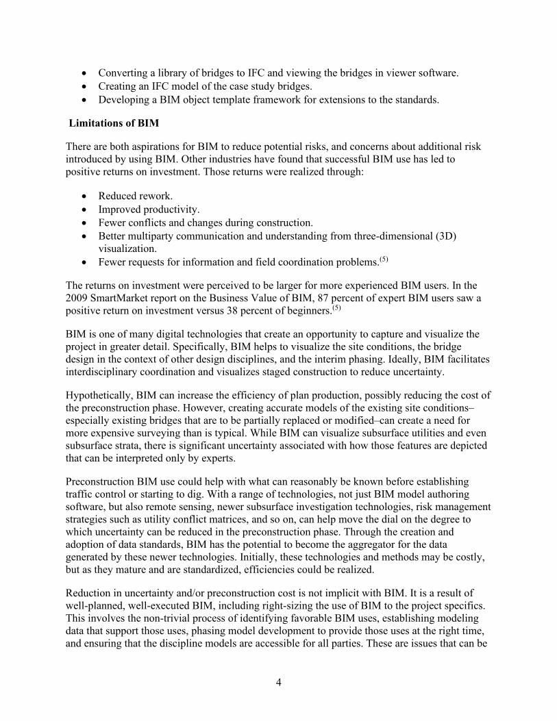
There are different levels of BIM. The terms BIG BIM and little bim differentiate the levels of sophistication in how BIM is used.(16) The term little bim describes using parametric 3D modeling software. The term BIG BIM describes a process leading to planned, managed collaboration, such as the exchange of carefully described, digital information at specified milestones. While little bim may bring efficiencies over traditional drafting methods, BIG BIM brings opportunities for clash avoidance ensuring adequate space between different components within a construction site and improved inter-disciplinary coordination methods and outcomes.
The BIM Dictionary(17) provides terms that describe different levels of collaboration and risk sharing behind how BIM is used. The term “Lonely BIM” refers to keeping digital information within each authoring discipline. The term “Social BIM” refers to a collaborative exchange of digital information between disciplines and organizations through a managed collaboration tool (i.e., real-time interaction via a managed server or cloud-based platform). Two additional levels are recognized, “Shy BIM,” where multiple disciplines may share models within a single organization, and “Friendly BIM,” where the models are shared as a courtesy, but are not officially recognized contractual documents.(18)
Combining graduations of process management (little bim, BIG BIM) and collaboration and risk sharing (Lonely BIM, Shy BIM, Friendly BIM, and Social BIM) results in the description of 12 levels of BIM (i.e., Lonely little bim through Social BIG BIM). Figure 2 provides examples for each level. Delivering Lonely little bim is much simpler than delivering Social BIG BIM. The latter takes much more careful attention to characterizing and scheduling electronic information exchanges, information management, and describing the collaboration framework. Social BIG BIM may not be applicable to most standard bridge projects, and existing frameworks such as Partnering agreements may support some of the collaboration management needs.
6
Figure 2: Flowchart. Examples of the 12 levels of BIM.
BIM Maturity and Digital Delivery
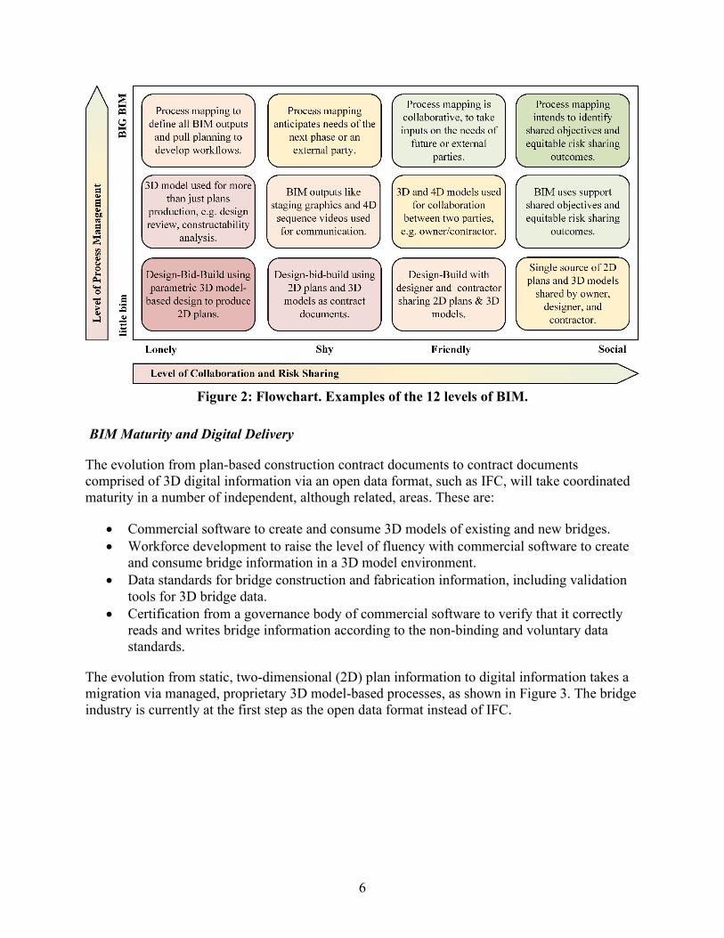
The evolution from plan-based construction contract documents to contract documents comprised of 3D digital information via an open data format, such as IFC, will take coordinated maturity in a number of independent, although related, areas. These are:
• Commercial software to create and consume 3D models of existing and new bridges. • Workforce development to raise the level of fluency with commercial software to create
and consume bridge information in a 3D model environment. • Data standards for bridge construction and fabrication information, including validation
tools for 3D bridge data. • Certification from a governance body of commercial software to verify that it correctly
reads and writes bridge information according to the non-binding and voluntary data standards.
The evolution from static, two-dimensional (2D) plan information to digital information takes a migration via managed, proprietary 3D model-based processes, as shown in Figure 3. The bridge industry is currently at the first step as the open data format instead of IFC.
7
Figure 3: Illustration. Digital migration from 2D plans to digital information.
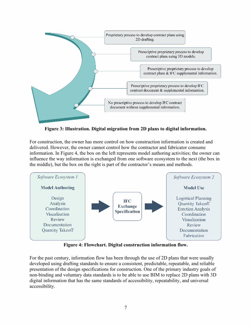
For construction, the owner has more control on how construction information is created and delivered. However, the owner cannot control how the contractor and fabricator consume information. In Figure 4, the box on the left represents model authoring activities; the owner can influence the way information is exchanged from one software ecosystem to the next (the box in the middle), but the box on the right is part of the contractor’s means and methods.
Figure 4: Flowchart. Digital construction information flow.
For the past century, information flow has been through the use of 2D plans that were usually developed using drafting standards to ensure a consistent, predictable, repeatable, and reliable presentation of the design specifications for construction. One of the primary industry goals of non-binding and voluntary data standards is to be able to use BIM to replace 2D plans with 3D digital information that has the same standards of accessibility, repeatability, and universal accessibility.

8
Agencies seeking to use BIM may consider carefully controlling the process of developing the contract documents for potential benefit from contractors and fabricators have a repeatable experience when navigating the digital contract documents. Until the four areas identified in above have achieved maturity, it will be difficult to develop and use 3D digital information successfully without following a specific process.
9
CHAPTER 2 CASE STUDY
Introduction
A key objective of this research was to document a bridge project delivered digitally using BIM, where a 3D-engineered model with attachments formed the primary construction contract document. A Utah Department of Transportation (UDOT) project was chosen to use as the case study to document in this research. The project was in design as the case study began and was under construction at the time of the site visit and report publication.
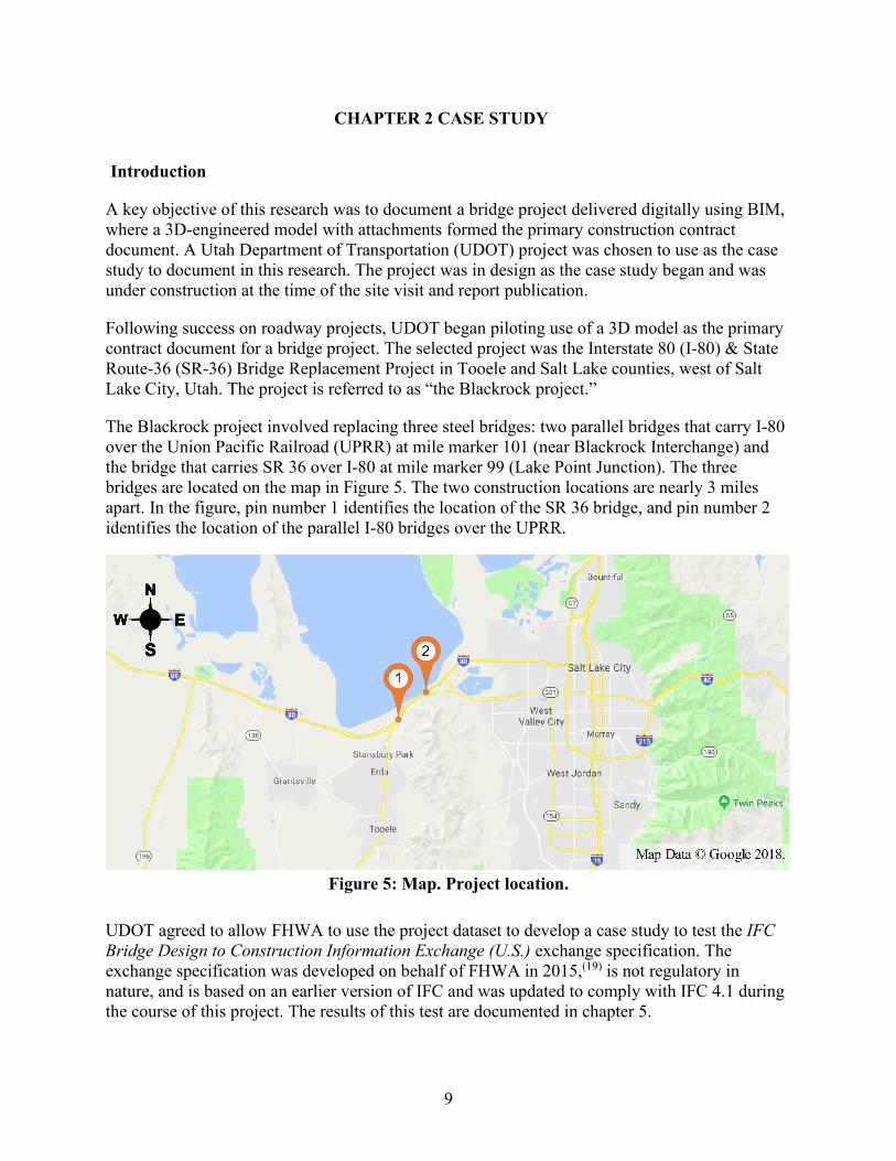
Following success on roadway projects, UDOT began piloting use of a 3D model as the primary contract document for a bridge project. The selected project was the Interstate 80 (I-80) & State Route-36 (SR-36) Bridge Replacement Project in Tooele and Salt Lake counties, west of Salt Lake City, Utah. The project is referred to as “the Blackrock project.”
The Blackrock project involved replacing three steel bridges: two parallel bridges that carry I-80 over the Union Pacific Railroad (UPRR) at mile marker 101 (near Blackrock Interchange) and the bridge that carries SR 36 over I-80 at mile marker 99 (Lake Point Junction). The three bridges are located on the map in Figure 5. The two construction locations are nearly 3 miles apart. In the figure, pin number 1 identifies the location of the SR 36 bridge, and pin number 2 identifies the location of the parallel I-80 bridges over the UPRR.
Figure 5: Map. Project location.
UDOT agreed to allow FHWA to use the project dataset to develop a case study to test the IFC Bridge Design to Construction Information Exchange (U.S.) exchange specification. The exchange specification was developed on behalf of FHWA in 2015,(19) is not regulatory in nature, and is based on an earlier version of IFC and was updated to comply with IFC 4.1 during the course of this project. The results of this test are documented in chapter 5.
10
Digital Delivery Goals
UDOT’s objectives for piloting digital delivery were broader than FHWA’s objectives for this case study. UDOT had a goal to implement mature, 3D model-based processes for design and construction. This project was the first pilot project for UDOT in which 3D model-based information exchanges were used for bridges. As a result, the bridge designs were developed and advertised within a BIM environment; that is, 3D engineered models formed the primary construction contract document. Specifically, the UDOT goals for the project were:(20)
• Develop a 3D model of the geometrics, structures design, and construction planning. • Deliver the project contract documents electronically, with plan sheets as needed. • Assist UDOT to progress their digital delivery initiative developing BIM standards,
workflow processes, and procedures for bridge design and construction. • Use the 3D model for design, construction, and management of the structures.
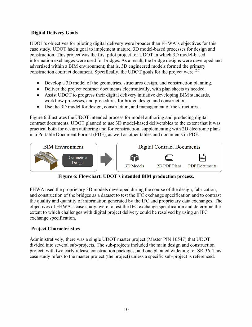
Figure 6 illustrates the UDOT intended process for model authoring and producing digital contract documents. UDOT planned to use 3D model-based deliverables to the extent that it was practical both for design authoring and for construction, supplementing with 2D electronic plans in a Portable Document Format (PDF), as well as other tables and documents in PDF.
Figure 6: Flowchart. UDOT's intended BIM production process.
FHWA used the proprietary 3D models developed during the course of the design, fabrication, and construction of the bridges as a dataset to test the IFC exchange specification and to contrast the quality and quantity of information generated by the IFC and proprietary data exchanges. The objectives of FHWA’s case study, were to test the IFC exchange specification and determine the extent to which challenges with digital project delivery could be resolved by using an IFC exchange specification.
Project Characteristics
Administratively, there was a single UDOT master project (Master PIN 16547) that UDOT divided into several sub-projects. The sub-projects included the main design and construction project, with two early release construction packages, and one planned widening for SR-36. This case study refers to the master project (the project) unless a specific sub-project is referenced.
11
Scope of Work
The project involved three bridge replacements at two locations along I-80 (Blackrock and the Tooele Interchange at Lake Point) with ancillary bin wall replacements at Blackrock, as well as changes to the roadway vertical alignment at Blackrock. The structures were designed for the anticipated 2040 traffic volumes. Minimizing the traffic impacts during construction was a specific objective.(20) The bridges that were replaced were:
• I-80 Eastbound over UPRR Bridge (2C-438) at Black Rock. • I-80 Westbound over UPRR Bridge (4C-438) at Black Rock. • Tooele Interchange Bridge (0C-583) at Lake Point.
The objectives of the I-80 Blackrock bridge replacements were:
• Reduce maintenance. • Improve horizontal and vertical clearances for the UPRR. • Accommodate three travel lanes in anticipation of future I-80 widening.(21)
The design of the Tooele Interchange Bridge (the SR-36 bridge) accommodated the geometric needs of a planned, future SR-36/SR-201 extension. UDOT developed the environmental documentation and completed the preliminary situation and layout for the SR-36/SR-201 extension.
The design scope of work related to BIM processes and deliverables(20) included five distinct elements for the consultant. First, the consultant had to be prepared to accommodate UDOT staff within the project development team. Second, those UDOT staff, if applicable, could be co-located in the consultant’s office with workstations and software licenses. Third, the consultant developed an implementation strategy to achieve the UDOT goals for BIM. Fourth, the consultant had to develop a summary report that evaluated processes and outcomes. Finally, the consultant had to incorporate the BIM tasks into the project delivery workflows.
The construction scope of work related to BIM processes and deliverables(22) included four distinct elements. First, the consultant inspection team used the model-based, electronic documents for the purposes of inspection. Second, the team updated the models throughout construction to reflect changes. Third, the team assisted in training the UDOT construction engineering management staff in using the BIM software, hardware, and processes. Finally, the team tracked model-based practices related to construction contract administration and produce a formal lessons-learned document.
Procurement Model
UDOT advertised the project through a Construction Manager/General Contractor (CM/GC) process. UDOT has used its CM/GC model successfully for a range of projects, including Accelerated Bridge Construction projects(23) and the initial Digital Delivery with Model-based Design and Construction (MBDC) pilot projects where the 3D roadway design data was the governing construction contract document.(24) The CM/GC process brings practical construction

12
skills and experience to the early design process to identify and mitigate risks, among other benefits.(23)
UDOT’s CM/GC process selects the consultant designer first. The consultant designer then participates in selecting a general contractor through the CM/GC process. The contractor initially has a professional services contract with UDOT providing construction management services with the right to negotiate a fair market price for the construction contract to provide general contractor services.(25) The fair market price is determined by reconciliation with an Independent Cost Estimate. If the contractor and UDOT cannot agree on a fair market price, then the final design is packaged for design-bid-build advertising. CM/GC provides opportunities for early-release construction packages.
The primary purpose of using CM/GC on this project was to identify and resolve issues with the BIM-based information exchanges. The consultant designer and contractor would use the project to assist UDOT to develop the Structures Division processes and procedures for BIM in project delivery. There were secondary benefits for mitigating other project risks, such as railroad coordination and maintenance of traffic during construction. Table 1 lists the parties involved in delivering the Blackrock project.
Table 1: Parties involved in delivering the Blackrock project Role Organization
Owner UDOT Region 2 Consultant Designer Michael Baker International and HDR, Inc. Construction Manager Granite Construction Contract Administration
UDOT Region 2
General Contractor Granite Fabricators Utah Pacific (Steel Plate Girders), Forterra (Prestressed Concrete
Girders), Harris Rebar (Steel Reinforcement) Site Conditions
The project involved two construction locations that are approximately 3 miles apart. The western site was the Tooele Interchange, where the SR-36 bridge was to be replaced. Figure 7 is an aerial view of the Tooele Interchange. In the figure, the green dots are one-tenth mile marker locations. The SR-36 bridge is identified in the figure.

13
Figure 7: Photograph. Aerial view of the Tooele Interchange and the SR-36 bridge.
The eastern site was east-northeast of the Blackrock Interchange, where parallel bridges carry I-80 over the UPRR (the I-80 bridges). Figure 8 is an aerial view of the Blackrock Interchange and the location of the I-80 bridges to the east-northeast. As in the previous figure, the green dots are one-tenth mile marker locations. The I-80 bridges are identified in the figure.
Figure 8: Photograph. Aerial view of the Blackrock Interchange and the I-80 bridges.
Existing Bridges
The I-80 eastbound lane (EBL) bridge over the UPRR was built in 1967. It was a continuous steel girder bridge with three spans and a skew angle of 67 degrees relative to the UPRR; there was no skew in the abutment. The total length was 325.8 ft and the longest span was 133.5 ft. The deck was cast-in-place concrete, which was replaced in 2002. Figure 9 shows the I-80 bridges and bin walls as viewed from the UPRR in March 2017.
14
Figure 9: Photograph. I-80 bridges from the UPRR looking west in March 2017.
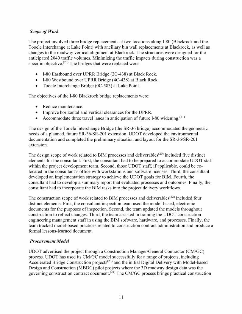
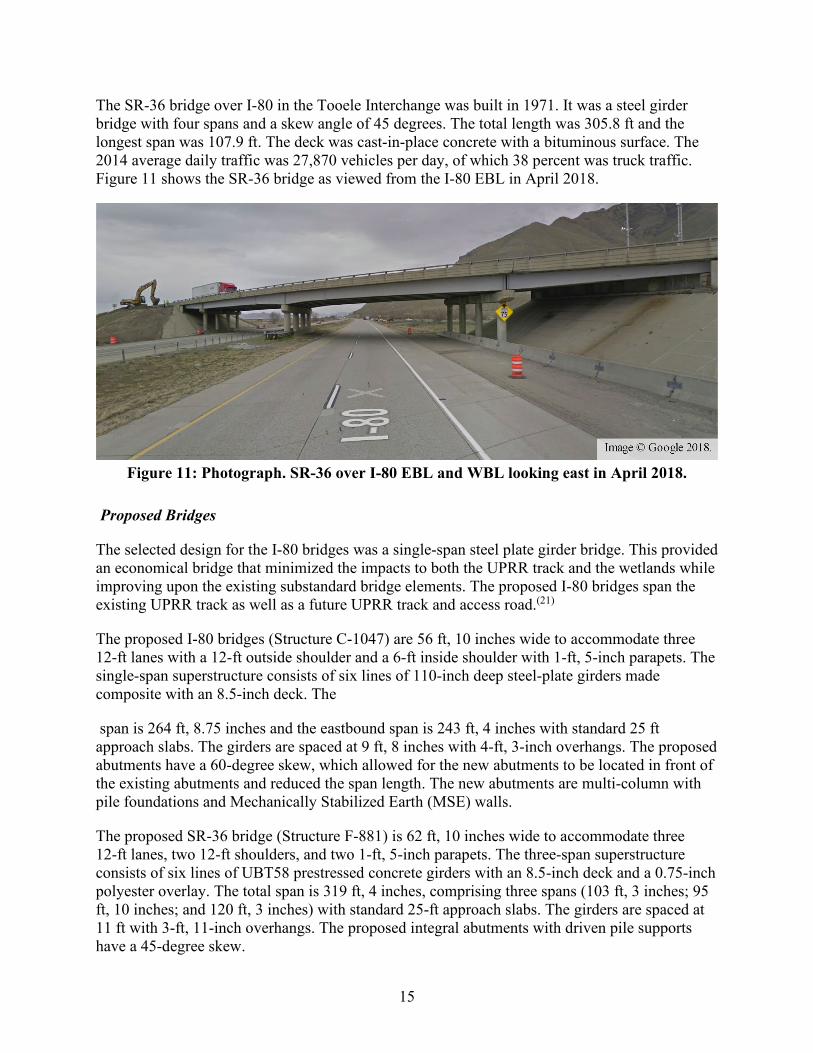
The I-80 westbound lane (WBL) bridge over the UPRR was built in 1967. It was a continuous steel girder bridge with three spans and a skew angle of 67 degrees relative to the UPRR; there was no skew in the abutment. The total length was 345.8 ft and the longest span was 141.7 ft. The deck was cast-in-place concrete, which was replaced in 2002.(21) The 2014 average daily traffic was 21,805 vehicles per day, of which 24 percent was truck traffic. Figure 10 shows one span of the I-80 WBL bridge and part of the bin walls viewed from the UPRR in March 2017.
Figure 10: Photograph. I-80 WBL over UPRR looking south in March 2017.
15
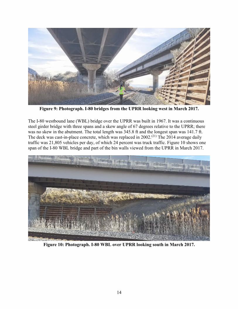
The SR-36 bridge over I-80 in the Tooele Interchange was built in 1971. It was a steel girder bridge with four spans and a skew angle of 45 degrees. The total length was 305.8 ft and the longest span was 107.9 ft. The deck was cast-in-place concrete with a bituminous surface. The 2014 average daily traffic was 27,870 vehicles per day, of which 38 percent was truck traffic. Figure 11 shows the SR-36 bridge as viewed from the I-80 EBL in April 2018.
Figure 11: Photograph. SR-36 over I-80 EBL and WBL looking east in April 2018.
Proposed Bridges
The selected design for the I-80 bridges was a single-span steel plate girder bridge. This provided an economical bridge that minimized the impacts to both the UPRR track and the wetlands while improving upon the existing substandard bridge elements. The proposed I-80 bridges span the existing UPRR track as well as a future UPRR track and access road.(21)
The proposed I-80 bridges (Structure C-1047) are 56 ft, 10 inches wide to accommodate three 12-ft lanes with a 12-ft outside shoulder and a 6-ft inside shoulder with 1-ft, 5-inch parapets. The single-span superstructure consists of six lines of 110-inch deep steel-plate girders made composite with an 8.5-inch deck. The
span is 264 ft, 8.75 inches and the eastbound span is 243 ft, 4 inches with standard 25 ft approach slabs. The girders are spaced at 9 ft, 8 inches with 4-ft, 3-inch overhangs. The proposed abutments have a 60-degree skew, which allowed for the new abutments to be located in front of the existing abutments and reduced the span length. The new abutments are multi-column with pile foundations and Mechanically Stabilized Earth (MSE) walls.
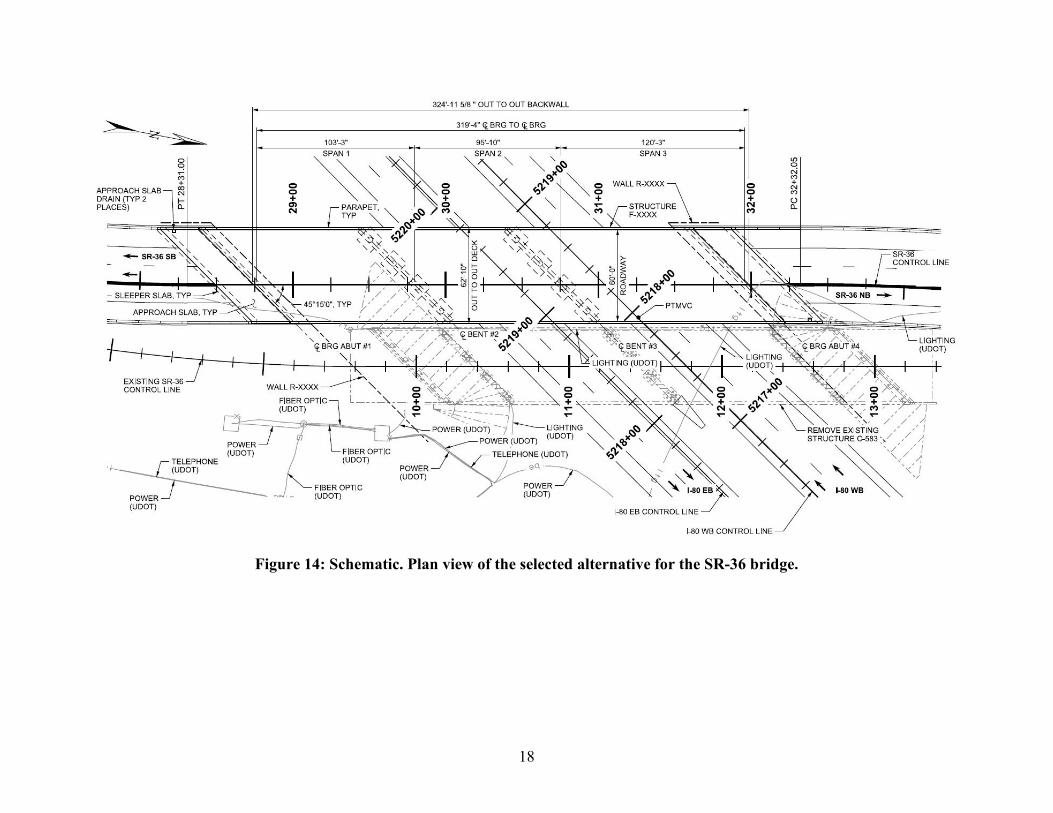
The proposed SR-36 bridge (Structure F-881) is 62 ft, 10 inches wide to accommodate three 12-ft lanes, two 12-ft shoulders, and two 1-ft, 5-inch parapets. The three-span superstructure consists of six lines of UBT58 prestressed concrete girders with an 8.5-inch deck and a 0.75-inch polyester overlay. The total span is 319 ft, 4 inches, comprising three spans (103 ft, 3 inches; 95 ft, 10 inches; and 120 ft, 3 inches) with standard 25-ft approach slabs. The girders are spaced at 11 ft with 3-ft, 11-inch overhangs. The proposed integral abutments with driven pile supports have a 45-degree skew.

16
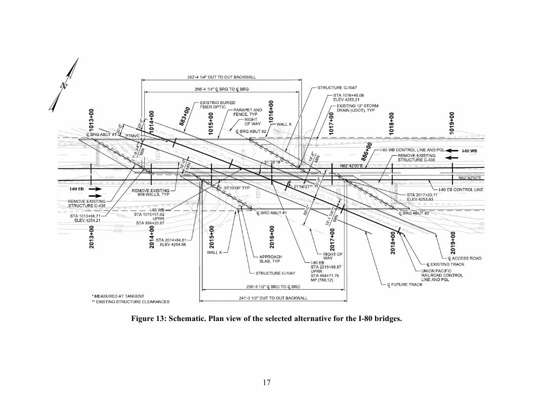
The SR-36 bridge, which has a superelevation transition across the deck, is on a new alignment adjacent to the original bridge. This enabled better maintenance of traffic during construction. Figure 12 shows the new SR-36 bridge adjacent to the existing SR-36 bridge. The new bridge was constructed using traditional construction methods.(26) Figure 13 shows the proposed configuration for the I-80 bridges.(21) Figure 14 shows the proposed configuration for the SR-36 bridge.(26)
Figure 12: Photograph. The new SR-36 bridge (left) alongside
the existing SR-36 bridge (right).
17
Figure 13: Schematic. Plan view of the selected alternative for the I-80 bridges.
18
Figure 14: Schematic. Plan view of the selected alternative for the SR-36 bridge.
19
Partnering
Construction partnering is a voluntary, structured approach to collaboration and teamwork between contracting parties on a construction project. Partnering is structured through a charter, which documents mutual goals and a non-binding commitment to collaborate to achieve them. Two hallmarks of partnering are resolving issues at the lowest level to avoid claims and disputes (often documented in the charter as a dispute resolution ladder) and team-based relationships that use open and transparent communication.
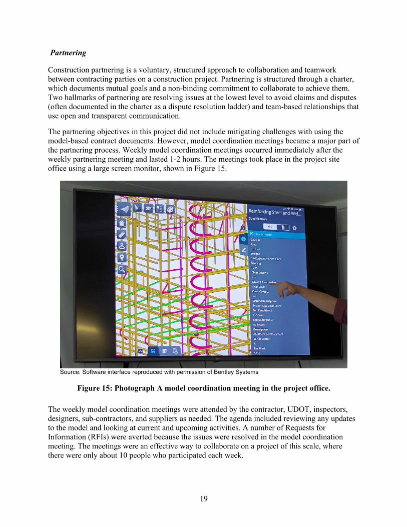
The partnering objectives in this project did not include mitigating challenges with using the model-based contract documents. However, model coordination meetings became a major part of the partnering process. Weekly model coordination meetings occurred immediately after the weekly partnering meeting and lasted 1-2 hours. The meetings took place in the project site office using a large screen monitor, shown in Figure 15.
Source: Software interface reproduced with permission of Bentley Systems
Figure 15: Photograph A model coordination meeting in the project office.
The weekly model coordination meetings were attended by the contractor, UDOT, inspectors, designers, sub-contractors, and suppliers as needed. The agenda included reviewing any updates to the model and looking at current and upcoming activities. A number of Requests for Information (RFIs) were averted because the issues were resolved in the model coordination meeting. The meetings were an effective way to collaborate on a project of this scale, where there were only about 10 people who participated each week.
20
BIM Processes
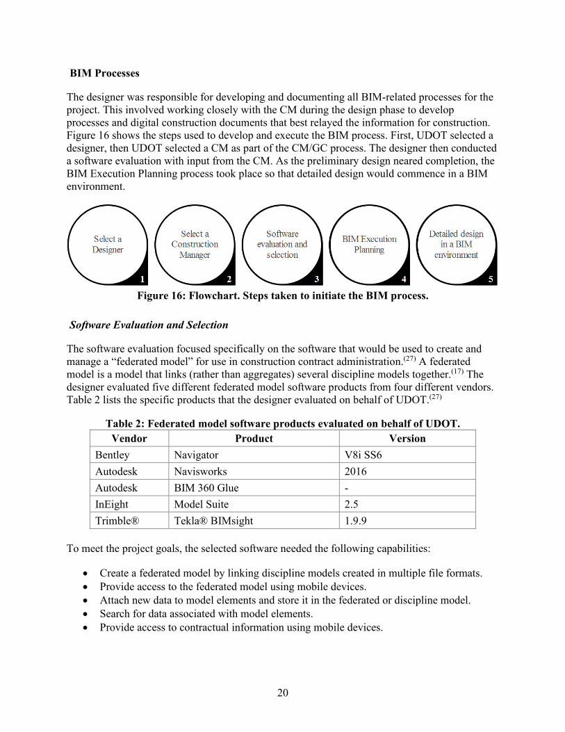
The designer was responsible for developing and documenting all BIM-related processes for the project. This involved working closely with the CM during the design phase to develop processes and digital construction documents that best relayed the information for construction. Figure 16 shows the steps used to develop and execute the BIM process. First, UDOT selected a designer, then UDOT selected a CM as part of the CM/GC process. The designer then conducted a software evaluation with input from the CM. As the preliminary design neared completion, the BIM Execution Planning process took place so that detailed design would commence in a BIM environment.
Figure 16: Flowchart. Steps taken to initiate the BIM process.
Software Evaluation and Selection
The software evaluation focused specifically on the software that would be used to create and manage a “federated model” for use in construction contract administration.(27) A federated model is a model that links (rather than aggregates) several discipline models together.(17) The designer evaluated five different federated model software products from four different vendors. Table 2 lists the specific products that the designer evaluated on behalf of UDOT.(27)
Table 2: Federated model software products evaluated on behalf of UDOT. Vendor Product Version
Bentley Navigator V8i SS6 Autodesk Navisworks 2016 Autodesk BIM 360 Glue - InEight Model Suite 2.5 Trimble® Tekla® BIMsight 1.9.9
To meet the project goals, the selected software needed the following capabilities:
• Create a federated model by linking discipline models created in multiple file formats. • Provide access to the federated model using mobile devices. • Attach new data to model elements and store it in the federated or discipline model. • Search for data associated with model elements. • Provide access to contractual information using mobile devices.

21
The products were also compared based on their capability to support saved views created in a discipline model or the federated model, as well as the ability to automate model connections.
The results of the model authoring, design review, and 3D coordination software evaluation were documented in the BIM Project Execution Plans (PxPs). The designer selected software for each discipline, as well as for interdisciplinary coordination and design review. The disciplines were document management, structures, roadway, construction survey, subsurface utilities, design review, and data augmentation. The selected software is shown in Table 3.(28)
Table 3: Software selected for use on the Blackrock project. Discipline Software Version
Document Management Bentley ProjectWise >= 10.00.01.67 Structures Bentley OpenBridge Modeler 08.11.12.64 (SS3) Structures Bentley ProStructures 08.11.14.238
(SS8) Roadway Bentley Power InRoads SS4 08.11.09.878
(SS4) Construction Survey Trimble® HCE not specified Subsurface Utilities Bentley Subsurface Utility Engineering 08.11.9.163 Review Bentley Navigator CONNECT 05.04.02.14 Review Bentley OpenRoads Navigator 10.00.03.10 Data Augmentation Bentley MicroStation® CONNECT Edition 10.06.00.38
Project Execution Planning
The designer led the BIM process and used a PxP to shepherd the process for the case study project. The PxP describes the approach to governing the BIM process and establishes the opportunities and responsibilities of the parties involved.(2) The designer documented the BIM process in three PxPs. There was a Level 1 PxP for the whole project and Level 2 PxPs for each of: model authoring, design review, and 3D coordination.
The PxPs had the following sections:
• Overview. • Project Information. • Model Authoring Goals and Objectives. • Roles/Responsibilities and Key Contacts. • Model Authoring Process Design. • Data Requirements for the Case Study Project. • Collaboration Procedures. • Quality Control Procedures. • Technological Infrastructure Needs. • Model Content and Reference Information.

22
• Model Structure. • Information Exchanges.
BIM Goals and Uses
BIM goals were described within each PxP for each of the specific processes covered by the PxP. The goals were:
• Ensure consistent element data sets are visible and transferable to subsequent BIM uses. • Develop discipline models that contain necessary elements to support each BIM use and
produce the LOD identified in the Model Progression Matrix. • Follow a logical model progression workflow that enables development continuity from
concept to construction. • Create a 3D visual aid for use in design and construction. • Provide a model review method that allows for detailed analysis, comment, comment
tracking, and resolution. • Ensure manageable spatial clash instances of components within construction site are
identified and either resolved through design or marked for potential relocation.
Specific objectives associated with the BIM goals were:
• Identify element data sets pertinent to fabrication and construction. • Test each element for visual compliance in authoring, review, and field software. • Identify necessary elements for each BIM use. • Progress models with minimal modification from design to construction. • Use the model(s) to assist all project participants to review and collaborate during the
design phase and the construction methods to be used. • Prepare component spatial clash reports and conduct weekly interdisciplinary
coordination meetings.
Roles and Responsibilities
The PxP described responsibilities for model authoring, dividing responsibility into disciplines (Structures, Roadway, Survey, and Subsurface Utility Engineering) and locations (I-80 bridges and Tooele Interchange bridge).(28) The responsibility for developing the PxP, model aggregation, model review, and general BIM management was not described in the PxP.
The designer coordinated and facilitated the multidisciplinary meetings necessary to create the PxPs. All team members (UDOT, designer, contractor, construction contract administration) participated in determining BIM goals and uses, establishing the software matrix and the collaboration platforms. The project used two managed collaboration platforms. First, UDOT’s Bentley ProjectWise server stored the official contract documents. Second, a Bluebeam Studio session provided by the contractor hosted linked documents such as PDF detail sheets and spreadsheets. The Bluebeam Studio session also hosted the files that the designer provided for reference information.
23
Collaboration Framework
The project team was dispersed geographically with team members in several Salt Lake City area offices and one member located outside of the state. The team collaborated via in-person meetings and teleconferences with screen sharing. Most BIM-related meetings took place in a conference room with screen sharing using a projector. Remote participants called in on the phone and viewed the projector screen via webinar.
The design team used a ProjectWise folder that functioned as a common data environment for digital collaboration during design and design review. The Bluebeam Studio session stored PDF files, Excel spreadsheets, and other documents that were attached to the 3D models with hyperlinks.
Information Management
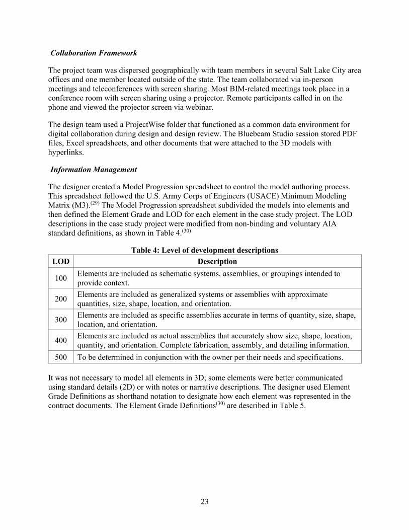
The designer created a Model Progression spreadsheet to control the model authoring process. This spreadsheet followed the U.S. Army Corps of Engineers (USACE) Minimum Modeling Matrix (M3).(29) The Model Progression spreadsheet subdivided the models into elements and then defined the Element Grade and LOD for each element in the case study project. The LOD descriptions in the case study project were modified from non-binding and voluntary AIA standard definitions, as shown in Table 4.(30)
Table 4: Level of development descriptions LOD Description
100 Elements are included as schematic systems, assemblies, or groupings intended to provide context.
200 Elements are included as generalized systems or assemblies with approximate quantities, size, shape, location, and orientation.
300 Elements are included as specific assemblies accurate in terms of quantity, size, shape, location, and orientation.
400 Elements are included as actual assemblies that accurately show size, shape, location, quantity, and orientation. Complete fabrication, assembly, and detailing information.
500 To be determined in conjunction with the owner per their needs and specifications.
It was not necessary to model all elements in 3D; some elements were better communicated using standard details (2D) or with notes or narrative descriptions. The designer used Element Grade Definitions as shorthand notation to designate how each element was represented in the contract documents. The Element Grade Definitions(30) are described in Table 5.
24
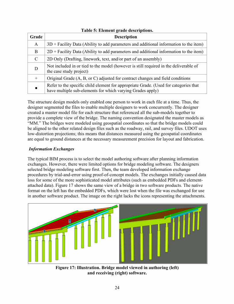
Table 5: Element grade descriptions. Grade Description
A 3D + Facility Data (Ability to add parameters and additional information to the item) B 2D + Facility Data (Ability to add parameters and additional information to the item) C 2D Only (Drafting, linework, text, and/or part of an assembly)
D Not included in or tied to the model (however is still required in the deliverable of the case study project)
+ Original Grade (A, B, or C) adjusted for contract changes and field conditions
● Refer to the specific child element for appropriate Grade. (Used for categories that have multiple sub-elements for which varying Grades apply)
The structure design models only enabled one person to work in each file at a time. Thus, the designer segmented the files to enable multiple designers to work concurrently. The designer created a master model file for each structure that referenced all the sub-models together to provide a complete view of the bridge. The naming convention designated the master models as “MM.” The bridges were modeled using geospatial coordinates so that the bridge models could be aligned to the other related design files such as the roadway, rail, and survey files. UDOT uses low-distortion projections; this means that distances measured using the geospatial coordinates are equal to ground distances at the necessary measurement precision for layout and fabrication.
Information Exchanges
The typical BIM process is to select the model authoring software after planning information exchanges. However, there were limited options for bridge modeling software. The designers selected bridge modeling software first. Then, the team developed information exchange procedures by trial-and-error using proof-of-concept models. The exchanges initially caused data loss for some of the more sophisticated model attributes (such as embedded PDFs and element-attached data). Figure 17 shows the same view of a bridge in two software products. The native format on the left has the embedded PDFs, which were lost when the file was exchanged for use in another software product. The image on the right lacks the icons representing the attachments.
Figure 17: Illustration. Bridge model viewed in authoring (left)
and receiving (right) software.

25
The design team convened a workshop with UDOT and the contractor early in the BIM process. The contractor took a typical plan sheet and color coded it with information they use and information that they do not need for construction and bidding, such as information on plans that UDOT uses for bridge management. This process enabled the team to identify which information should be in the model for either the contractor or UDOT, and the most consumable format for that information.
The parties worked through the bridges element-by-element to identify what data was needed and whether it should be modeled or included as an attachment. The workshop produced a table of elements and listed the specific geometry attributes, National Bridge Inventory (NBI) data, details, notes, and special provisions that should be included, as well as whether that information was included as embedded data or as an attachment. Generally, geometric and NBI data were embedded as attributes, while details and special provisions were linked as attachments. The bridge elements listed in the table were:
• Piles. • Granular Backfill. • Bent Pile Cap. • Integral Abutment Pile Cap. • Bearings. • Steel Girders. • Diaphragms/Cross Braces. • Deck. • Parapets. • Approach Slab. • Sleeper Slab. • Wingwall/Finwall.
The contractor trained and supported their sub-contractors to work with the digital data. The contractor extracted data in small pieces, for example, segmented by specific work packages and packages for sub-contractors to bid. The contractor’s concrete reinforcement supplier preferred the IFC format for digital data. However, the model authoring software supported IFC 2.3 exchange specification, which does not fully support bridge geometry. While the contract documents were not in IFC format, the designers did send concrete and reinforcement information to Harris Rebar using IFC 2.3.
The main objective of the IFC 2.3 exchange was to determine if it would be valuable for the project despite the limitations of the IFC 2.3 specification related to bridge elements. As anticipated, there was data loss (attributes and parametric relationships were lost), but the physical geometry was preserved. The export created individual elements for each bar. This resulted in a large file size and limited value. It was possible to create schedules, but important information such as the spacing and cover could not be extracted automatically.
26
Contract Documents
The official contract documents were identified in a certification memo, which was signed and sealed by the Engineer of Record. UDOT used the certification memo process on previous digital delivery with MBDC projects. The digital contract documents were comprised of three main file types: 3D models in Bentley DGN format, 2D standard details in PDF format, and document files in PDF and Excel® spreadsheet format. All the official contract documents were placed in a read-only “Deliverables” folder on the UDOT ProjectWise server.
The official contract documents were the master model for each bridge with its attachments. The master model was an empty DGN file with the sub-models for that bridge referenced in. Saved views were created in each master model. Saved views displayed the bridge information according to specific view angles, view styles (such as solid, shaded, or wireframe), and a selection of visible elements. There was no call-out text or text-based dimensions in the models; this would have duplicated information that was already available in the model. The models were created to scale, and the contractor would be able to scale off any dimensions they needed.
In addition to the contractual Bentley DGN files with attached PDF and document files, the designers produced non-contractual files (for information only) as a courtesy for the contractor and inspectors. The non-contractual files were Bentley i-model files that could be viewed using the Bentley mobile application, OpenRoads Navigator. The i-model files were read-only files and included saved views for ease of navigation. The project has significant railroad coordination issues and permitting needs. The designer created a modified set of plans for UPRR for coordination and permitting.
Using BIM on the Project
Every party involved in the project used BIM to some extent for a range of functions. These include design, estimating, fabrication, construction, inspection, and oversight. The following sections describe how BIM was used and the benefits and issues that were encountered.
Model Authoring
Bridge model authoring began after the geometry was set at the geometry review milestone. The model authoring used the Bentley software ecosystem for interoperable roadway and bridge design production. The specific software with version numbers is shown in Table 3.
UDOT desired that data, such as the respective NBI number for each bridge, be embedded in the models as attributes attached to the bridge and roadway model element geometry. The Item Type feature in the Connect Edition of MicroStation®, a more recent version of the software than was used for design authoring, was used to attach data to the elements. The designers established spreadsheets to manage the Item Type attributes and maintained consistency using data look-ups.
Concern for keeping the model light and navigable and software limitations meant that some parts were not fully detailed within the model. Rather, there were hyperlinks in the i-model to the detail sheets. Most standard details did not need to be included in the model. Some were included in the model with representative graphics, but separate PDF detail sheets were the controlling contract document for those elements. Examples of details that were not be modeled are:
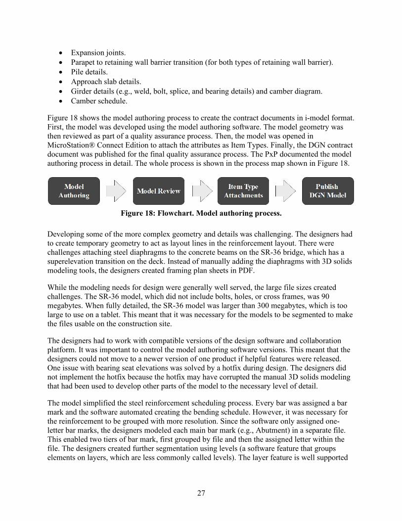
27
• Expansion joints. • Parapet to retaining wall barrier transition (for both types of retaining wall barrier). • Pile details. • Approach slab details. • Girder details (e.g., weld, bolt, splice, and bearing details) and camber diagram. • Camber schedule.
Figure 18 shows the model authoring process to create the contract documents in i-model format. First, the model was developed using the model authoring software. The model geometry was then reviewed as part of a quality assurance process. Then, the model was opened in MicroStation® Connect Edition to attach the attributes as Item Types. Finally, the DGN contract document was published for the final quality assurance process. The PxP documented the model authoring process in detail. The whole process is shown in the process map shown in Figure 18.
Figure 18: Flowchart. Model authoring process.
Developing some of the more complex geometry and details was challenging. The designers had to create temporary geometry to act as layout lines in the reinforcement layout. There were challenges attaching steel diaphragms to the concrete beams on the SR-36 bridge, which has a superelevation transition on the deck. Instead of manually adding the diaphragms with 3D solids modeling tools, the designers created framing plan sheets in PDF.
While the modeling needs for design were generally well served, the large file sizes created challenges. The SR-36 model, which did not include bolts, holes, or cross frames, was 90 megabytes. When fully detailed, the SR-36 model was larger than 300 megabytes, which is too large to use on a tablet. This meant that it was necessary for the models to be segmented to make the files usable on the construction site.
The designers had to work with compatible versions of the design software and collaboration platform. It was important to control the model authoring software versions. This meant that the designers could not move to a newer version of one product if helpful features were released. One issue with bearing seat elevations was solved by a hotfix during design. The designers did not implement the hotfix because the hotfix may have corrupted the manual 3D solids modeling that had been used to develop other parts of the model to the necessary level of detail.
The model simplified the steel reinforcement scheduling process. Every bar was assigned a bar mark and the software automated creating the bending schedule. However, it was necessary for the reinforcement to be grouped with more resolution. Since the software only assigned one-letter bar marks, the designers modeled each main bar mark (e.g., Abutment) in a separate file. This enabled two tiers of bar mark, first grouped by file and then the assigned letter within the file. The designers created further segmentation using levels (a software feature that groups elements on layers, which are less commonly called levels). The layer feature is well supported
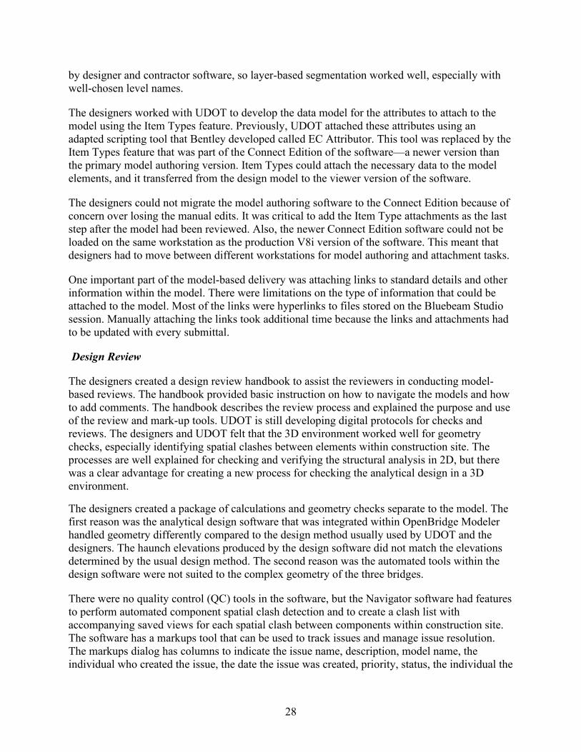
28
by designer and contractor software, so layer-based segmentation worked well, especially with well-chosen level names.
The designers worked with UDOT to develop the data model for the attributes to attach to the model using the Item Types feature. Previously, UDOT attached these attributes using an adapted scripting tool that Bentley developed called EC Attributor. This tool was replaced by the Item Types feature that was part of the Connect Edition of the software—a newer version than the primary model authoring version. Item Types could attach the necessary data to the model elements, and it transferred from the design model to the viewer version of the software.
The designers could not migrate the model authoring software to the Connect Edition because of concern over losing the manual edits. It was critical to add the Item Type attachments as the last step after the model had been reviewed. Also, the newer Connect Edition software could not be loaded on the same workstation as the production V8i version of the software. This meant that designers had to move between different workstations for model authoring and attachment tasks.
One important part of the model-based delivery was attaching links to standard details and other information within the model. There were limitations on the type of information that could be attached to the model. Most of the links were hyperlinks to files stored on the Bluebeam Studio session. Manually attaching the links took additional time because the links and attachments had to be updated with every submittal.
Design Review
The designers created a design review handbook to assist the reviewers in conducting model-based reviews. The handbook provided basic instruction on how to navigate the models and how to add comments. The handbook describes the review process and explained the purpose and use of the review and mark-up tools. UDOT is still developing digital protocols for checks and reviews. The designers and UDOT felt that the 3D environment worked well for geometry checks, especially identifying spatial clashes between elements within construction site. The processes are well explained for checking and verifying the structural analysis in 2D, but there was a clear advantage for creating a new process for checking the analytical design in a 3D environment.
The designers created a package of calculations and geometry checks separate to the model. The first reason was the analytical design software that was integrated within OpenBridge Modeler handled geometry differently compared to the design method usually used by UDOT and the designers. The haunch elevations produced by the design software did not match the elevations determined by the usual design method. The second reason was the automated tools within the design software were not suited to the complex geometry of the three bridges.
There were no quality control (QC) tools in the software, but the Navigator software had features to perform automated component spatial clash detection and to create a clash list with accompanying saved views for each spatial clash between components within construction site. The software has a markups tool that can be used to track issues and manage issue resolution. The markups dialog has columns to indicate the issue name, description, model name, the individual who created the issue, the date the issue was created, priority, status, the individual the

29
issue is assigned to, and a due date. The design team preferred to use Bluebeam for making comments. The designer collated Navigator and Bluebeam comments.
The model workflow was simpler than the usual process of creating and coordinating notes on plan sheets. Notes were only placed once, eliminating the need to coordinate repeated notes. This let the design team spend more time on the design and on checking the model. The designers felt they spent more time on tasks that added value than with the plans-production process.
Quality Control
The designers planned to perform a series of visual checks, geometry checks, automated component spatial clash checks, and model integrity checks. The model integrity checks were to verify that the element naming, grouping, and parametrics were consistent with the standards.
QC was challenging, in part because there were no established model-based processes and in part because the software did not have any specific QC features. The traditional highlighting and initialing QC processes used for 2D plan sets did not transfer; it is not possible to highlight in the model in the way that one can highlight on paper or in a PDF file. Instead, the designers created QC checklists for geometry, attributes, and Item Types. There were three checking roles: modeler, checker (performed by the Engineer of Record), and QC checker, performed by one designated individual.
Shop Drawings
The model streamlined the shop drawing review process. The fabricators and the reviewer had a better understanding of the design, which made it easier to digest the shop drawings. The shop drawing approvals were faster because the detailer was familiar with what the design looked like and the designer had coordinated what information to pass on to the fabricator. However, the girder fabricators were not able to use the models developed in design directly in fabrication because the DGN files were not interoperable with their proprietary software.
Steel Fabrication
The steel plate girder fabricator has used computerized methods for critical fabrication processes for a decade. The steel plate girder fabricator needed to transfer information from the UDOT model into their software for the purposes of estimating, drilling, cutting, and layout. While the steel plate girder fabricator has digitized the fabrication processes, all layout was hand-checked. The high value of each girder made it worth the additional effort of hand checking because the large cost of an error. Figure 19 shows the fabricated girders.

30
Figure 19: Photo. Fabricated steel plate girders for the I-80 bridges in the fabrication yard.
There was no way to exchange the DGN contract documents into the steel plate girder fabricator’s shop drawing software, Tekla®. The detailer had to use their normal process to create the detailing models. The DGN contract documents became the source of the design instead of the PDF plans. The DGN models did enable the steel plate girder fabricator to interact with the design in new ways. The steel plate girder fabricator was able to view the models, which enabled visual analysis to plan maintenance of traffic and site logistics, as well as the delivery and erection procedures and to look at windows of opportunity for setting girders.
Until there is a feasible way to exchange data between the software products used in design and fabrication, the steel plate girder fabricator will not be capable of using UDOT models directly to fabricate bridges. This would involve software vendors who produce the authoring (design) software and the receiving (fabrication) software to incorporate a common exchange format for bridge models. If the steel plate girder fabricator could receive models in their software, it would save time with detailing.
Prestressed Concrete Girder Fabrication
The prestressed concrete girder fabricator had used BIM for three years and used Revit and Navisworks in their processes for fabricating elements for vertical construction. The prestressed concrete girder fabricator has spent a lot of time creating 2D production drawings and found that it is less efficient to showing every reinforcement bar and every strand in the model as the software becomes less responsive with very detailed models. The main difference between prestressed concrete girder fabrication for bridges and fabrication for vertical construction is how the structures deflect. The girders for the SR-36 bridge, shown in Figure 20, had complex geometry with both a vertical curve and a superelevation transition.
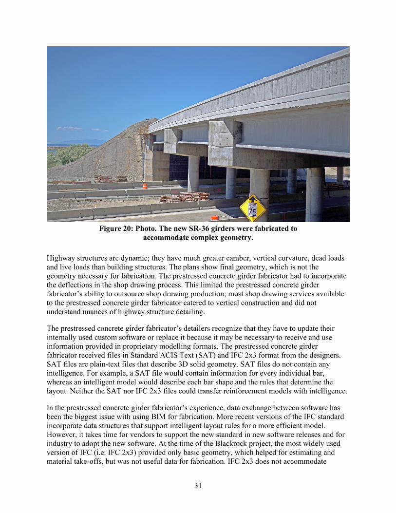
31
Figure 20: Photo. The new SR-36 girders were fabricated to
accommodate complex geometry.
Highway structures are dynamic; they have much greater camber, vertical curvature, dead loads and live loads than building structures. The plans show final geometry, which is not the geometry necessary for fabrication. The prestressed concrete girder fabricator had to incorporate the deflections in the shop drawing process. This limited the prestressed concrete girder fabricator’s ability to outsource shop drawing production; most shop drawing services available to the prestressed concrete girder fabricator catered to vertical construction and did not understand nuances of highway structure detailing.
The prestressed concrete girder fabricator’s detailers recognize that they have to update their internally used custom software or replace it because it may be necessary to receive and use information provided in proprietary modelling formats. The prestressed concrete girder fabricator received files in Standard ACIS Text (SAT) and IFC 2x3 format from the designers. SAT files are plain-text files that describe 3D solid geometry. SAT files do not contain any intelligence. For example, a SAT file would contain information for every individual bar, whereas an intelligent model would describe each bar shape and the rules that determine the layout. Neither the SAT nor IFC 2x3 files could transfer reinforcement models with intelligence.
In the prestressed concrete girder fabricator’s experience, data exchange between software has been the biggest issue with using BIM for fabrication. More recent versions of the IFC standard incorporate data structures that support intelligent layout rules for a more efficient model. However, it takes time for vendors to support the new standard in new software releases and for industry to adopt the new software. At the time of the Blackrock project, the most widely used version of IFC (i.e. IFC 2x3) provided only basic geometry, which helped for estimating and material take-offs, but was not useful data for fabrication. IFC 2x3 does not accommodate

32
intelligent layout (such as for reinforcement) or bridge structure deflections. The designer provided an Excel spreadsheet output from the analytical design software with the camber and deflections
Reinforcement Bar Fabrication
The reinforcement fabricator’s normal workflow was to receive IFC files containing the external concrete geometry and perform the bar layout around the joints using Tekla® Structures software. Receiving IFC files of the reinforcement for the Blackrock project reversed the fabricator’s process. The rebar fabricator used the IFC files to detail pour sequences and reinforcement embedments.
The reinforcement fabricator could not extract some information in the IFC files, such as bar marks and spacing. Nor could the reinforcement fabricator model external concrete faces using the information in the IFC files. It was necessary for the reinforcement fabricator to model external concrete faces to produce placement drawings, which involved additional effort. It was also more difficult for the reinforcement fabricator to verify the schedules that the designer provided. Nevertheless, the reinforcement fabricator was able to use much of the information in the IFC files for the fabrication process.
The reinforcement fabricator had to create shop drawings for the ironworkers laying out the bars in the field because they could not use the models. The reinforcement fabricator would have had to teach ironworkers how to place using the 3D model. The information needed to place bars was not available in the viewer software that the ironworkers used.
The reinforcement fabricator exported the IFC file with exterior concrete dimensions to an Excel® table. Then, the reinforcement fabricator typed the dimensions into their bespoke fabrication software. This was a normal process as the fabrication software did not read Tekla® Structures files either. Some of the reinforcement machines used automation; for example, the machine cut the programmed length, then the bar moved to the table bender for the programmed bend. Figure 21 shows a digitally generated tag for a bundle of bars for the approach slab on the SR-36 bridge. The tag shows a hand-written correction, but the origin of the correction was not explored.
The Blackrock project made the reinforcement fabricator aware of the potential benefits of 3D design and digital exchanges. However, it would take significant training investments to train ironworkers with the skill level necessary to use the 3D models for field layout. The reinforcement fabricator noted, however, that new recruits have been exposed to technology and they do not want to work in 2D.
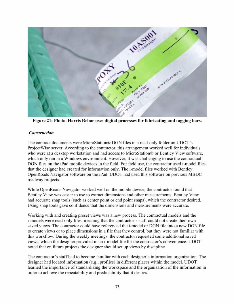
33
Figure 21: Photo. Harris Rebar uses digital processes for fabricating and tagging bars.
Construction
The contract documents were MicroStation® DGN files in a read-only folder on UDOT’s ProjectWise server. According to the contractor, this arrangement worked well for individuals who were at a desktop workstation and had access to MicroStation® or Bentley View software, which only ran in a Windows environment. However, it was challenging to use the contractual DGN files on the iPad mobile devices in the field. For field use, the contractor used i-model files that the designer had created for information only. The i-model files worked with Bentley OpenRoads Navigator software on the iPad. UDOT had used this software on previous MBDC roadway projects.
While OpenRoads Navigator worked well on the mobile device, the contractor found that Bentley View was easier to use to extract dimensions and other measurements. Bentley View had accurate snap tools (such as center point or end point snaps), which the contractor desired. Using snap tools gave confidence that the dimensions and measurements were accurate.
Working with and creating preset views was a new process. The contractual models and the i-models were read-only files, meaning that the contractor’s staff could not create their own saved views. The contractor could have referenced the i-model or DGN file into a new DGN file to create views or to place dimensions in a file that they control, but they were not familiar with this workflow. During the weekly meetings, the contractor requested some additional saved views, which the designer provided in an i-model file for the contractor’s convenience. UDOT noted that on future projects the designer should set up views by discipline.
The contractor’s staff had to become familiar with each designer’s information organization. The designer had located information (e.g., profiles) in different places within the model. UDOT learned the importance of standardizing the workspace and the organization of the information in order to achieve the repeatability and predictability that it desires.
34
The contractor was more familiar with extracting measurements and dimensions from PDF files and felt less confident in the measurements and dimensions extracted using the model-based workflow. The contractor struggled to extract dimensions from complex geometry, especially inclined planes and non-perpendicular locations. The contractor had trouble with repeatability when extracting such dimensions. This led to increased time spent double and triple checking measurements from the model. The designer added a level of reference lines to aid dimension snaps. Nevertheless, the contractor still had diminished confidence extracting dimensions and relied much more heavily on their surveyor for layout and layout checking.
The contractor found that the compatible software did not have tools that supported the ways that the contractor wanted to interact with the model for construction. The contractor’s surveyor imported the DGN contract documents into Trimble® Business Center (TBC) to prepare data to layout construction. The exchange from DGN to TBC was a manual process. While the attributes were lost, the survey control information that was the critical information needed in TBC was preserved. UDOT’s previous MBDC projects had made use of the DGN to TBC exchange, and as expected, the OpenRoads Designer data that contained the roadway information transferred well into TBC. The contractor also extracted KMZ files to create views in Google Earth.
There was a full-time construction surveyor on the Blackrock project, which was atypical for a job of the scope and scale of the Blackrock project according to the contractor. The surveyor had worked in a 3D environment for decades and felt confident interacting with the contractual models. Normally, the surveyor would lay out critical points and the crafts would do additional layout with a tape. The surveyor had to check layout that normally would be checked with a tape.
In general, the contractor’s surveyor was supportive of the change to 3D deliverables since surveyors work in a 3D environment and traditionally have to convert 2D deliverables into their 3D environment. To lay out the SR-36 bridge, the contractor’s surveyor extracted the haunch heights from the model and the attached tables to create a survey model, which was checked against the design model. When everything matched, it created confidence in the model-based workflow. Figure 22 shows the new SR-36 bridge on the new alignment adjacent to the existing bridge. The new bridge has complex geometry created by a significant skew and a superelevation transition across the deck.
The contractor’s surveyor noted some inefficiencies in the 3D workflow. For instance, it was difficult to manage elements that repeat on a regular spacing, in particular for reinforcement bars and piles. The surveyor had to measure each individual spacing in the model. Normally, a short note on plans would indicate the number of piles at a designated, regular spacing. As a result, the surveyor had to lay out every pile at a specific location instead of laying out one or two reference piles and letting the pile driving crew pull a measuring tape to lay out the repeating piles.
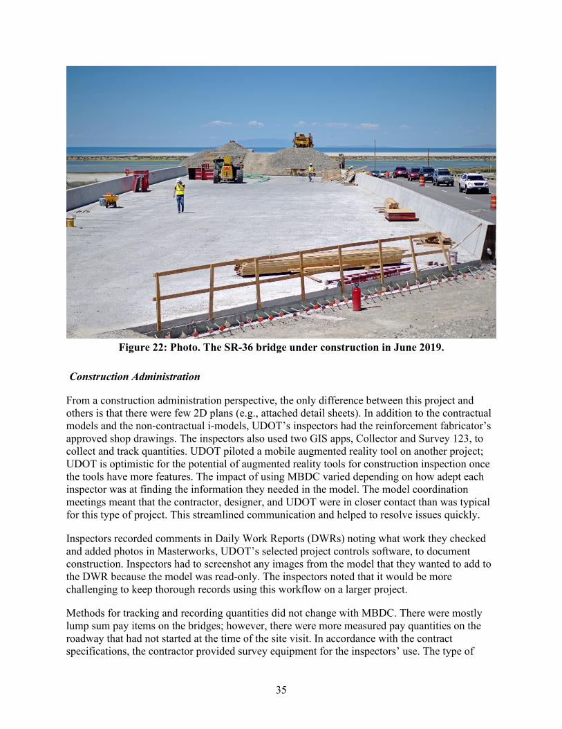
35
Figure 22: Photo. The SR-36 bridge under construction in June 2019.
Construction Administration
From a construction administration perspective, the only difference between this project and others is that there were few 2D plans (e.g., attached detail sheets). In addition to the contractual models and the non-contractual i-models, UDOT’s inspectors had the reinforcement fabricator’s approved shop drawings. The inspectors also used two GIS apps, Collector and Survey 123, to collect and track quantities. UDOT piloted a mobile augmented reality tool on another project; UDOT is optimistic for the potential of augmented reality tools for construction inspection once the tools have more features. The impact of using MBDC varied depending on how adept each inspector was at finding the information they needed in the model. The model coordination meetings meant that the contractor, designer, and UDOT were in closer contact than was typical for this type of project. This streamlined communication and helped to resolve issues quickly.
Inspectors recorded comments in Daily Work Reports (DWRs) noting what work they checked and added photos in Masterworks, UDOT’s selected project controls software, to document construction. Inspectors had to screenshot any images from the model that they wanted to add to the DWR because the model was read-only. The inspectors noted that it would be more challenging to keep thorough records using this workflow on a larger project.
Methods for tracking and recording quantities did not change with MBDC. There were mostly lump sum pay items on the bridges; however, there were more measured pay quantities on the roadway that had not started at the time of the site visit. In accordance with the contract specifications, the contractor provided survey equipment for the inspectors’ use. The type of
36
survey equipment provided lacked the positional accuracy to check structure elevations. The survey equipment enabled the inspectors to “trust but verify” more work than was possible using stake-based inspection methods. Inspectors used the survey equipment to spot check horizontal positions for the roadway and roadside items and to measure quantities. It was common that the inspector and the contractor would walk together to measure pay estimates and removals quantities. These were typically interim payment quantities with a lump sum the final payment quantity.
Federal Oversight
The Blackrock project was a federally funded project. At the time of the site visit, the FHWA Utah Division Office had completed one construction review. The Division Office does not make extensive use of plans for construction oversight. The Division Office project engineers did participate in a few MBDC meetings. MBDC was challenging for Division Office staff conducting Plans, Specifications, and Estimate reviews as they did not have readily available access to the software or training to review MBDC projects. On previous MBDC projects, FHWA did in-person reviews where UDOT or its consultant assisted the Division Office staff to navigate the model.
Handover Information
The PxP considered uses for design, estimating, construction, and handover (also known as as-built records). However, UDOT was still developing effective procedures for creating and storing as-built records. On the Blackrock project, the contractor did not have a model deliverable after construction. The contractor was instructed to turn in survey shots for certain elements—in particular anything installed underground (such as foundations and buried utilities), as well as any revisions to the plans to reflect as-built conditions.
The contractor’s surveyor used survey instruments daily to perform and check layout. At the time of the site visit, construction had proceeded to plan and there had not been a need to collect revisions. The intent had been to use traditional as-built mark-up processes and to provide the mark-ups to the designers, who would update the models to create the 3D as-built record.
Conclusion
The project produced valuable insights to further refine digital delivery with MBDC. At the time of writing this report, the design was complete, and the construction was underway. The new SR-36 bridge had been constructed and the girders for the I-80 bridges had been fabricated. UDOT had already achieved its goal of constructing a bridge using digital delivery with MBDC. There were issues along the way, but the parties were committed to completing the project successfully and would continue to work through them.
Limitations
The main limitations of digital delivery with MBDC were the general lack of experience across industry with 3D models of bridges and difficulties using 3D models in the various software products involved in designing, estimating, fabricating, and building bridges.
37
Limited Experience
Road designers and contractors have used 3D models to design and build roads for well over a decade, but software for geometrically modeling bridges in 3D is new and not-yet fully featured. The CM/GC procurement process enabled UDOT to select the most qualified design and construction teams to deliver the project. Nevertheless, this was a first attempt to use 3D modeling for bridges for most people involved in the project.
The complexity of the Blackrock meant that those involved in the project gained a wealth of experience. There were not yet clearly established or documented workflows or manuals for creating or navigating 3D models of bridges. As a result, knowledge transferred organically between individuals through in-person meetings. This was an effective way to transfer these skills on a project of this scale, but standardization, documentation, and formal training would be needed to expand digital delivery of MBDC to more and larger bridge projects.
Interoperability
The designers created the models within a single software ecosystem but needed to use several different software products and two different generations of the software to create the fully featured models. The models also included links to information stored in different file formats in a different collaboration environment. It was a complex task to then exchange this information into the various software ecosystems used by the contractor and their sub-contractors. In fact, many of the attempts to use digital exchange had very limited results.
One of the main concerns was the potential for data loss, even within the design authoring ecosystem, for instance using the Bentley View software. At the start of the project, there were two different Bentley mobile tools: Navigator and OpenRoads Navigator. These were subsequently combined into one product. However, the mobile products worked with the non-contractual i-models, not the contractual DGN files. What is more, the i-models developed for the original Navigator software were not compatible with the new, combined software.
It was possible to use the Bentley View software on Windows tablets, but the contractor preferred a mobile device with a different operating system. This meant that either the designer or the contractor had to take responsibility for converting the contractual DGN models to non-contractual i-models. The contractor was then responsible for verifying that the information had converted with the necessary level of completeness.
The export to i-model preserved the visual presentation options in the DGN at the time of creation. Once the i-model was created, you could not change the view type, for instance to switch between solid, transparent, and wireframe views. Different view types were preferred for different applications; solid views were preferred for communicating with stakeholders; transparent views were useful for viewing component spatial clashes; and wireframe views show the edges of objects which made it easier to measure dimensions.
There is not yet a voluntary, consensus standard exchange specification for transferring bridge analytical models to physical models. Analytical modeling uses many assumptions that need to be interpreted. Seamlessly exchanging analytical models and physical models, especially for bridges, is challenging. At the time that the designers were performing analytical design, the
38
integration features between Bentley analysis tools and OpenBridge Modeler were relatively new. The products have matured significantly since then. On the Blackrock project, the designers preferred to use a third-party analysis software tool and found it was faster to create the analytical model by hand than to export geometry from the physical model.
Opportunities
Despite the many challenges, there were a number of promising outcomes of using digital delivery with MBDC according to the project team.
Visualization
The model provided a visualization tool that both technical and non-technical stakeholders benefited from. Technical stakeholders benefited in unexpected ways; in particular, fabricators felt that the shop drawing review process was accelerated because everyone had a consistent understanding of the design. Fabricators were able to plan the delivery and erection more easily.
Collaboration
During design, the ProjectWise managed collaboration environment gave designers access to the design files for all disciplines. Bridge designers depended on the alignment data as a constraint to their design, but the ability to view other disciplines’ files helped to coordinate the bridge design. Designers could reference the files from other disciplines into their working files, allowing them to check for and avoid component spatial clashes. The model also simplified the process of coordinating notes; there was a single source of data rather than repeated information that should be synchronized with every change.
The weekly model coordination meetings during design and construction had far-reaching benefits according to the project team. There was an exchange of information among designers, fabricators, inspectors, and tradespeople regarding how they look at different elements and what their priorities are for information. The close working relationship forged during model coordination meetings led to effective communication throughout construction.
Next Steps
At the time of the site visit in June 2019, the Blackrock project was less than half-way complete. While the girders for the I-80 bridges had been fabricated, they were not yet delivered and installed. UDOT would continue learning a great deal through the remainder of the construction project. UDOT’s second MBDC bridge project would benefit from the lessons learned on Blackrock, as well as from maturing bridge modeling software and mobile applications.
Support and Training
The Blackrock team learned quickly that support and training were key ingredients of success. Many of the challenges were resolved with more familiarity or with the support of more experienced users. The five-minute model demonstration provided on the site visit would have taken two hours to execute at the start of the project. Surveyors, who have worked with 3D

39
models for decades, performed or checked critical activities, such as layout. With more experience, tradespeople may take on more of these responsibilities.
This project team spent considerable time with sub-contractors to help them learn how to navigate and locate information in the model. One reason for using the CM/GC process was to create an opportunity for the contractor and their sub-contractors to have this knowledge transfer before they had a limited time window to estimate a firm, fixed price to do the work. Not all sub-contractors would need to use the 3D aspects of the model; striping and guardrail installation, for example, are fairly simple activities that do not significantly change based on 3D geometrics. However, craft workers should have extensive training to use 3D models instead of plans.
Standardization
UDOT’s primary goal of digital delivery with MBDC is to have an efficient means of delivering project information through a consistent, repeatable process. There were two primary designers on the Blackrock project, and the contractor had to learn how to navigate two different approaches to placing information in the file. UDOT is in the process of standardizing the presentation of information and the organization of the digital files to achieve with MBDC the same repeatability that contractors experience with plan sets. This could occur through saved views, file naming conventions, a standard workspace for model authoring, or as yet unknown strategies. Repeatability is important for all consumers of the contract information, such as checkers, reviewers, inspectors, and permitting agencies.
Digital Exchange Specifications
Reliably automating the digital exchange of information is the ultimate goal. Current methods of digital information exchange involve manually selecting the information, manually converting it into a different file format, and manually verifying that the information has been converted without corruption or data loss. This is time-consuming and involves advanced skills. Manually re-creating digital information was a common strategy on the Blackrock project because it eliminated the uncertainty of the digital exchange process.
The goal of the IFC Bridge project internationally and the Transportation Pooled Fund project TPF-5(372) Building Information Modeling (BIM) for Bridges and Structures nationally is creating an open data exchange specification for automated digital exchanges. TPF-5(372) aims to create a non-binding and voluntary national industry consensus standard for the digital exchange of bridge information from design to construction and a second national industry consensus standard for the digital exchange from design to fabrication. FHWA, UDOT, and more than a dozen other State Transportation Agencies are part of TPF-5(372).
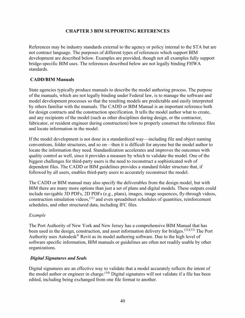
40
CHAPTER 3 BIM SUPPORTING REFERENCES
References may be industry standards external to the agency or policy internal to the STA but are not contract language. The purposes of different types of references which support BIM development are described below. Examples are provided, though not all examples fully support bridge-specific BIM uses. The references described below are not legally binding FHWA standards.
CADD/BIM Manuals
State agencies typically produce manuals to describe the model authoring process. The purpose of the manuals, which are not legally binding under Federal law, is to manage the software and model development processes so that the resulting models are predictable and easily interpreted by others familiar with the manuals. The CADD or BIM Manual is an important reference both for design contracts and the construction specification. It tells the model author what to create, and any recipients of the model (such as other disciplines during design, or the contractor, fabricator, or resident engineer during construction) how to properly construct the reference files and locate information in the model.
If the model development is not done in a standardized way—including file and object naming conventions, folder structures, and so on—then it is difficult for anyone but the model author to locate the information they need. Standardization accelerates and improves the outcomes with quality control as well, since it provides a measure by which to validate the model. One of the biggest challenges for third-party users is the need to reconstruct a sophisticated web of dependent files. The CADD or BIM guidelines provides a standard folder structure that, if followed by all users, enables third-party users to accurately reconstruct the model.
The CADD or BIM manual may also specify the deliverables from the design model, but with BIM there are many more options than just a set of plans and digital models. These outputs could include navigable 3D PDFs, 2D PDFs (e.g., plans), images, image sequences, fly-through videos, construction simulation videos,(31) and even spreadsheet schedules of quantities, reinforcement schedules, and other structured data, including IFC files.
Example
The Port Authority of New York and New Jersey has a comprehensive BIM Manual that has been used in the design, construction, and asset information delivery for bridges.(32)(33) The Port Authority uses Autodesk® Revit as its model authoring software. Due to the high level of software specific information, BIM manuals or guidelines are often not readily usable by other organizations.
Digital Signatures and Seals
Digital signatures are an effective way to validate that a model accurately reflects the intent of the model author or engineer in charge.(34) Digital signatures will not validate if a file has been edited, including being exchanged from one file format to another.

41
Digital signatures are more secure than electronic signatures, but there is usually a cost to acquire and maintain each digital signature certificate. Digital or electronic seals are a separate issue, since they may fall under the domain of the state board of engineering and land surveying.(35) The agency’s approach to signing and sealing the digital deliverables is usually explained within the CADD/BIM manuals.
Bridge Design Manual
The Bridge Design Manual is a manual that State agencies typically produce to provide guidance and policy for developing bridge designs, including data sources, decision support frameworks, milestones, and submittal instructions. While the New York State DOT incorporates plans production and 3D modeling guidance in the Bridge Design Manual,(36) this is not a typical practice. For instance, the Michigan DOT has a separate guideline for plan production.(37) As a result, Bridge Design Manuals may not need significant revision to incorporate BIM-related content. However, Bridge Design Manuals may inform bridge designers regarding how BIM can support design functions such as public outreach, design reviews, and constructability reviews.
Example
The New York State DOT has developed guidance for modeling bridges in 3D using Bentley® MicroStation software. The guidance is located in Section 14.2.6 of the 2017 Bridge Design Manual.(36)
BIM/CADD Workspace and Template Files
States are identifying benefits from economies of scale when investing in developing parametric BIM templates as part of a CADD or BIM workspace. This is a common practice for roadway design and is appropriate for bridge design (especially for new alignment and full replacement projects) because most agencies have standard types for abutments, piers, girders, barriers, deck templates, and so on. Providing templates in a CADD or BIM workspace helps ensure that designs are compliant with standards and creates efficiencies with design development and quality control since all users are familiar with the folder structure and naming conventions. Standardization may be useful when trying to support third-party users.
Agencies consider the cost effectiveness of centralizing resources to develop a workspace that is fit for the intended use and providing technical support and training to consultants to use it effectively. If the consultants do not use the agency’s workspace, it may lead to a lack of consistency in the electronic deliverables and prevent future use of the data beyond design.
Examples
Through its Development of 3D and 4D Bridge Models and Plans, Michigan DOT is in the process of developing some bridge templates to work with its CADD workspace, as well as training materials for bridge engineers.(37)
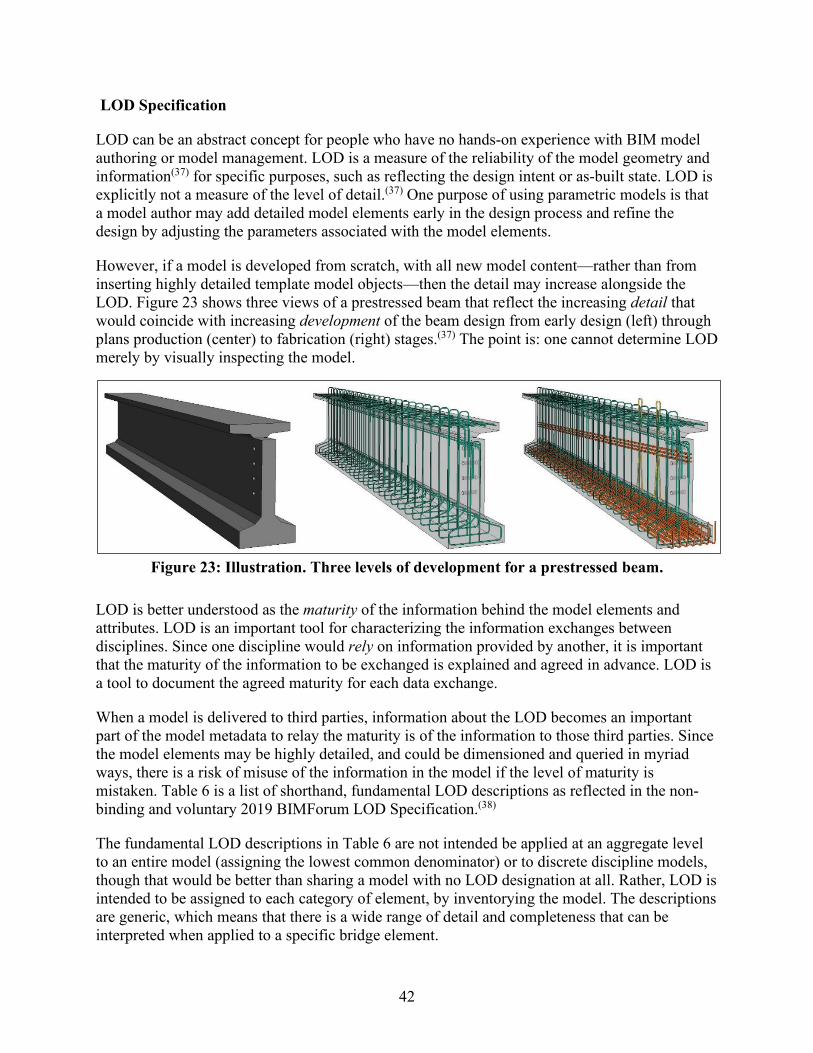
42
LOD Specification
LOD can be an abstract concept for people who have no hands-on experience with BIM model authoring or model management. LOD is a measure of the reliability of the model geometry and information(37) for specific purposes, such as reflecting the design intent or as-built state. LOD is explicitly not a measure of the level of detail.(37) One purpose of using parametric models is that a model author may add detailed model elements early in the design process and refine the design by adjusting the parameters associated with the model elements.
However, if a model is developed from scratch, with all new model content—rather than from inserting highly detailed template model objects—then the detail may increase alongside the LOD. Figure 23 shows three views of a prestressed beam that reflect the increasing detail that would coincide with increasing development of the beam design from early design (left) through plans production (center) to fabrication (right) stages.(37) The point is: one cannot determine LOD merely by visually inspecting the model.
Figure 23: Illustration. Three levels of development for a prestressed beam.
LOD is better understood as the maturity of the information behind the model elements and attributes. LOD is an important tool for characterizing the information exchanges between disciplines. Since one discipline would rely on information provided by another, it is important that the maturity of the information to be exchanged is explained and agreed in advance. LOD is a tool to document the agreed maturity for each data exchange.
When a model is delivered to third parties, information about the LOD becomes an important part of the model metadata to relay the maturity is of the information to those third parties. Since the model elements may be highly detailed, and could be dimensioned and queried in myriad ways, there is a risk of misuse of the information in the model if the level of maturity is mistaken. Table 6 is a list of shorthand, fundamental LOD descriptions as reflected in the non-binding and voluntary 2019 BIMForum LOD Specification.(38)
The fundamental LOD descriptions in Table 6 are not intended be applied at an aggregate level to an entire model (assigning the lowest common denominator) or to discrete discipline models, though that would be better than sharing a model with no LOD designation at all. Rather, LOD is intended to be assigned to each category of element, by inventorying the model. The descriptions are generic, which means that there is a wide range of detail and completeness that can be interpreted when applied to a specific bridge element.
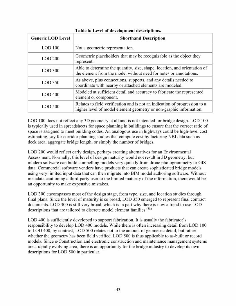
43
Table 6: Level of development descriptions. Generic LOD Level Shorthand Description
LOD 100 Not a geometric representation.
LOD 200 Geometric placeholders that may be recognizable as the object they represent.
LOD 300 Able to determine the quantity, size, shape, location, and orientation of the element from the model without need for notes or annotations.
LOD 350 As above, plus connections, supports, and any details needed to coordinate with nearby or attached elements are modeled.
LOD 400 Modeled at sufficient detail and accuracy to fabricate the represented element or component.
LOD 500 Relates to field verification and is not an indication of progression to a higher level of model element geometry or non-graphic information.
LOD 100 does not reflect any 3D geometry at all and is not intended for bridge design. LOD 100 is typically used in spreadsheets for space planning in buildings to ensure that the correct ratio of space is assigned to meet building codes. An analogous use in highways could be high-level cost estimating, say for corridor planning studies that compute cost by factoring NBI data such as deck area, aggregate bridge length, or simply the number of bridges.
LOD 200 would reflect early design, perhaps creating alternatives for an Environmental Assessment. Normally, this level of design maturity would not result in 3D geometry, but modern software can build compelling models very quickly from drone photogrammetry or GIS data. Commercial software vendors have products that can create sophisticated bridge models using very limited input data that can then migrate into BIM model authoring software. Without metadata cautioning a third-party user to the limited maturity of the information, there would be an opportunity to make expensive mistakes.
LOD 300 encompasses most of the design stage, from type, size, and location studies through final plans. Since the level of maturity is so broad, LOD 350 emerged to represent final contract documents. LOD 300 is still very broad, which is in part why there is now a trend to use LOD descriptions that are tailored to discrete model element families.(38)
LOD 400 is sufficiently developed to support fabrication. It is usually the fabricator’s responsibility to develop LOD 400 models. While there is often increasing detail from LOD 100 to LOD 400, by contrast, LOD 500 relates not to the amount of geometric detail, but rather whether the geometry has been field verified. LOD 500 is thus applicable to as-built or record models. Since e-Construction and electronic construction and maintenance management systems are a rapidly evolving area, there is an opportunity for the bridge industry to develop its own descriptions for LOD 500 in particular.
44
Example
The growing need to specify highly granular information exchanges led to the development of element-specific LOD descriptions, or so-called element-level LOD specifications which is a voluntary specification that is not required under Federal law. The BIMForum publishes an annual revision to what is now the industry standard LOD specification, supported by industry organizations including the AIA, the Associated General Contractors of America, the Precast/Prestressed Concrete Institute, and the National Institute of Steel Detailing. (38) It is also referenced by the National Institute of Building Sciences.(39)
The non-binding and voluntary BIMForum LOD Specification begins with a list of fundamental LOD definitions for LOD 100, LOD 200, LOD 300, LOD 350, LOD 400, and LOD 500 before embarking on a comprehensive list of element-level LOD definitions for over 100 building element classes. The non-binding and voluntary BIMForum element-level LOD definitions use the UniFormat™ and OmniClass™ classification systems to organize the building elements.
A LOD specification is a reference specification that serves many purposes. It tells model authors which information to progress. It enables model managers to systematically review the quality and sufficiency of a model. Third-party model recipients can use it to verify that the information received reflects the agreed information for that exchange. As a result, an inventory of model elements and their LOD designations is important metadata for all model submissions.
There is no LOD specification that comprehensively covers bridge elements. The non-binding and voluntary 2019 BIMForum LOD specification includes only four bridge-specific definitions, representing two concrete and two steel girders, respectively.(38)
Project Execution Plan
PxPs are usually both a project management tool and an information management tool. The PxP is intended to service all the needs to support effective BIM execution. Creating a PxP is a robust way to identify and prioritize BIM uses specific to the project’s unique characteristics and plan the information exchanges to support them. The PxP becomes a tool to document the rights and duties of model authors and the model manager(s).
The PxP is the framework for collaboration and creates a plan to meet all the needs of secure and accessible information management. The PxP is also a means of developing the collaboration tool by identifying things that could go wrong and designing the processes or technology to manage those risks. For example, a secure document management system with user authentication and carefully assigned permissions could mitigate against the risks of referencing the wrong file or accidentally editing a file.
Agencies are challenged to balance providing flexibility to the bridge engineer to identify the BIM uses to support with the need to predict the level of effort and cost associated with using BIM on the project. Agencies would benefit from a decision-support tool that could identify BIM uses based on project characteristics. An agency could develop a set of standard PxP templates for categories of bridge project types to avoid the risk of scope creep after executing a contract.
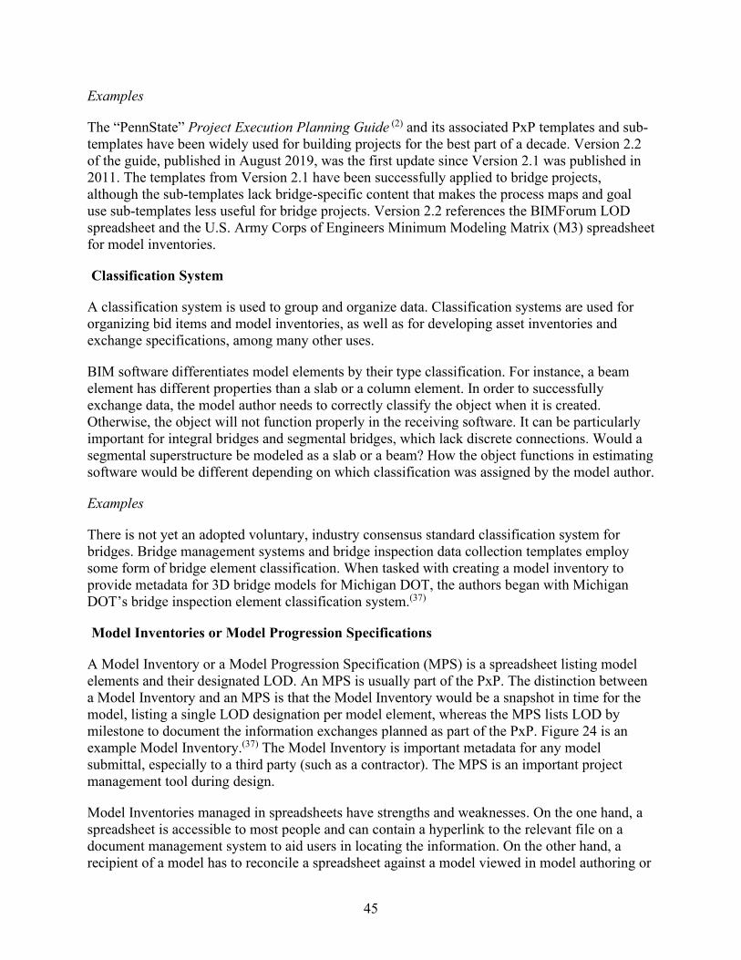
45
Examples
The “PennState” Project Execution Planning Guide (2) and its associated PxP templates and sub-templates have been widely used for building projects for the best part of a decade. Version 2.2 of the guide, published in August 2019, was the first update since Version 2.1 was published in 2011. The templates from Version 2.1 have been successfully applied to bridge projects, although the sub-templates lack bridge-specific content that makes the process maps and goal use sub-templates less useful for bridge projects. Version 2.2 references the BIMForum LOD spreadsheet and the U.S. Army Corps of Engineers Minimum Modeling Matrix (M3) spreadsheet for model inventories.
Classification System
A classification system is used to group and organize data. Classification systems are used for organizing bid items and model inventories, as well as for developing asset inventories and exchange specifications, among many other uses.
BIM software differentiates model elements by their type classification. For instance, a beam element has different properties than a slab or a column element. In order to successfully exchange data, the model author needs to correctly classify the object when it is created. Otherwise, the object will not function properly in the receiving software. It can be particularly important for integral bridges and segmental bridges, which lack discrete connections. Would a segmental superstructure be modeled as a slab or a beam? How the object functions in estimating software would be different depending on which classification was assigned by the model author.
Examples
There is not yet an adopted voluntary, industry consensus standard classification system for bridges. Bridge management systems and bridge inspection data collection templates employ some form of bridge element classification. When tasked with creating a model inventory to provide metadata for 3D bridge models for Michigan DOT, the authors began with Michigan DOT’s bridge inspection element classification system.(37)
Model Inventories or Model Progression Specifications
A Model Inventory or a Model Progression Specification (MPS) is a spreadsheet listing model elements and their designated LOD. An MPS is usually part of the PxP. The distinction between a Model Inventory and an MPS is that the Model Inventory would be a snapshot in time for the model, listing a single LOD designation per model element, whereas the MPS lists LOD by milestone to document the information exchanges planned as part of the PxP. Figure 24 is an example Model Inventory.(37) The Model Inventory is important metadata for any model submittal, especially to a third party (such as a contractor). The MPS is an important project management tool during design.
Model Inventories managed in spreadsheets have strengths and weaknesses. On the one hand, a spreadsheet is accessible to most people and can contain a hyperlink to the relevant file on a document management system to aid users in locating the information. On the other hand, a recipient of a model has to reconcile a spreadsheet against a model viewed in model authoring or
46
model viewing software to be able to determine the LOD of each model element and how it may reliably be applied. The user may also have to reference a third document, the LOD specification.
Figure 24: Illustration. A model inventory for a proposed bridge.
Examples
The Model Inventory in Figure 24 includes a classified list of bridge elements and sub-elements, identifies the responsible party (or model author), the specific file name that contains the information, and in this case designates the primary and secondary authorized uses, rather than LOD. There are tabs in the spreadsheet for an Existing Conditions model, the Proposed Design model, and a Temporary Works model.
Model View Definition
An MVD specifies a specific subset of the IFC schema for a particular discipline and a particular information exchange. For instance, MVDs can be developed for the hand-off of bridge design information to construction and/or to fabrication. An MVD describes specific data necessary by indicating particular data fields that are populated for particular object types. Data within an MVD may be made conditional based on how the object is described, such as based on object type, OmniClass™ classification, LOD, and/or other attributes. For example, a plate model element needs to provide its thickness.
Software vendors use MVDs to ensure that their software successfully reads and writes IFC files that satisfy the information needs for the disciplines and uses that their software supports. Model authors and recipients of bridge information can also use an MVD to validate that an IFC file fulfills the information for that particular exchange. For example, a structural analysis MVD would call for the Modulus of Elasticity be present for the material of components used within a
47
girder section, while a construction MVD would not need such information. Data may be validated against an MVD to determine if it passes or fails.
To create an IFC file that validates against a particular MVD, the model authoring software would need to use proper object type classifications, which would impart the applicable data. For example, a plate in a girder system should be described using the IfcPlate object type (rather than generically or using some other type) or the plate data would not validate. Some attributes may be directly described on data structures (e.g., IfcPlate.Tag for a piece mark to be printed on a plate for fabrication). Other attributes may follow a graph of data structures (e.g., IfcPlate.Representation.Representations["Body"].Items[0]\IfcExtrudedAreaSolid.Depth). Attributes may be simple values (e.g., a length), or may refer to pre-determined data structures (e.g., IfcExtrudedAreaSolid for 3D geometry described by a cross section extruded linearly).
Element-level LOD specifications indicate data to include for each type of element at each designated LOD. For example, LOD 200 for girders may prescribe only the general layout of girders along a span, while higher levels (e.g., LOD 400) prescribe exact dimensions, stiffener plates, bolts, welds, and reinforcement bars. The data provided within a model could exceed the designated LOD, although not all of it would necessarily be reliable. For example, a model author may start a new design by inserting parametric model elements from a standard library that is sufficiently detailed to support final plans. Even though all the data is available, the necessary analysis and design is not complete, and that data is not reliable. As another example, a light fixture affixed to a parapet may show exact dimensions from a specific manufactured product, even though the intent is to show that a light fixture at that location.
The data provided within a model may also be less than what is prescribed for the designated LOD in cases where details simply do not exist. For example, a sidewalk could be intentionally designed without reinforcement. A particular model could have varying LOD levels for different elements and systems. For example, on a design-build project where construction starts before the complete design is finished, piers and abutments may have a high LOD, while the reinforcement in the deck and parapets may be at a lower LOD.
The interaction of LOD with MVDs can be done by describing technical specifications that are conditional upon a particular LOD classification (e.g., LOD 300). While LOD is used primarily as a declarative mechanism, it can also be used to automatically validate data for meeting the expected LOD. Each element may have an attribute associated where the LOD is declared. However, such use depends on the granularity of how objects are classified. For example, if there is a classification for "sidewalk" where LOD 400 calls for reinforcement, then a sidewalk without reinforcement would fail a validation test, even if that is what is intended. To pass validation, there would need to be a classification for “sidewalk with reinforcement” and “sidewalk without reinforcement,” and distinct LOD for both.
As IFC is designed to be used internationally, such granular classification is qualified by the particular authority (e.g., the BIMForum LOD Specification), where a generic mechanism is in place to associate classification with any object (IfcRelAssociatesClassification relationship). If an MVD were to be determined dependent upon LOD levels, then technical requirements can be made conditional upon declared LOD levels.
48
Example
The IFC Bridge Design to Construction Information Exchange (U.S.) MVD was developed in 2016 using IFC version 4.1.(19) The MVD was developed to handle the exchange of information typically included in a set of plans for most representative bridge types in the United States. The MVD was developed using a dataset for one steel bridge and one concrete bridge(40) and further tested as indicated in this report.
IFC development for bridges has subsequently continued internationally as part of the fast-tracked IFC Bridge project. Four IFC 4 MVDs have been developed: Bridge Reference View, Alignment-based Bridge Reference View, Bridge Design Transfer View, and Bridge Asset Management Handover View. The MVDs will be tested by software vendors and then will proceed through a balloting process. If approved, the four MVDs will become the official IFC 4.2 candidate standard, a private, voluntary standard.(14) The Bridge Design Transfer View is most relevant for construction.
Geospatial Distance Distortions
An issue that is unique to BIM for Bridges is the need to manage geospatial distance distortions.(37) The issue arises in States that conduct roadway design on a wide area mapping projection that distorts horizontal distances. Since the bridge model is dependent upon the roadway alignment and profile, the bridge model will inherit these distance distortions. As a result, distances measured in the model are distorted in relation to equivalent distances measured on the ground. Ground distances can be computed by applying a location-specific combined scale factor that is provided as part of the survey metadata delivered with the base map.
This issue is not new to bridge design. Bridge engineers usually avoid this issue by being careful to separate geospatial information (e.g., coordinates, roadway stations) from local information (e.g., bridge dimensions). This is no longer an option when the bridge model is referenced into the federated model where it aligns to the roadway and other discipline models (which include distance distortions). A ground-distance-scaled bridge model would not line up correctly.
Example
This issue is discussed in detail in the Phase II Report for the Michigan DOT Development of 3D and 4D Bridge Models and Plans research,(37) which offers alternative strategies for managing geospatial distance distortions. One is to separate the overall bridge model that is referenced into the federated model from the models used for detailing and fabrication. Another is to identify if the distortion introduced by referencing the roadway model is large enough to be a concern. In states that use low distortion projections for design and construction, this is a viable solution.

49
CHAPTER 4 BIM TECHNICAL SPECIFICATIONS FOR BRIDGES
This chapter provides information for agencies to consider when drafting technical specifications to implement the use of BIM for bridge design and construction. While there are examples of criteria that some agencies have used in the past, there is no one universal standard that applies to all bridge projects.
Introduction
In the past, the design intent was conveyed to contractors with static plan sets delivered on paper or in PDF documents. Agencies are beginning to use digital 3D models to communicate the design intent to contractors. BIM technical specifications can help to clarify the information contained in these 3D models so that it is universally accessible and unambiguously interpreted.
The transition from low-tech CADD drafting to more sophisticated BIG BIM, especially at the collaboration levels of Friendly BIM and Social BIM, is an enormous gulf to cross. Project managers rarely get involved in the details of CADD production or file management and focus on the plan set. However, the details of digital data are fundamental to Friendly BIG BIM. The technical aspects relating to electronic products can be described in a scope of work statement that also alerts designers to the BIM-related needs and references BIM collaboration standards.
The buildings industry has used contract addenda to manage the use of BIM. This practice can be considered for the highway industry as well. Two sources for example BIM-related contract addenda include the AIA’s two BIM addenda(41) and ConsensusDocs.(7) Another resource is the BIM Universal Addendum used by the Pennsylvania State University.(42)
Technical Specifications for BIM-Based Design
BIM technical specifications for design establish the framework for using BIM to create, store, manipulate, and read the digital data to develop and document the design. This includes:
• Describing the overarching processes,• Specifying the specific software tools,• Establishing the milestones and specifications for information exchange, and• Identifying the format and content of the deliverables.
Determining BIM-Related Roles and Responsibilities
Sophisticated BIM use elevates the importance of what was once a lower-level role of CADD production and management. The consequences of poor CADD management were limited to inefficiencies in plans production, but the consequences of poor BIM management can lead to miscommunication between disciplines that result in costly errors or omissions. Establishment of new key staff roles of model manager(43) and model element author(44) and consideration of how to allocate new responsibilities are important components of BIM technical specifications. For example:

50
• How is responsibility assigned for errors caused by software, especially when using exchange formats?
• How is responsibility assigned for loss of productivity if the cloud-based document management system is offline?
• How is responsibility assigned for redesign costs when a difference is identified between disciplines?
• How is responsibility assigned if decisions were made on data at a lower LOD than expected?
A PxP is usually used to designate the responsible parties.(39) (2) While the PxP identifies the specific parties who may be responsible, the scope of work may specify capabilities for some of the key roles, such as the model manager.(43)
Model Manager or BIM Manager
The model manager or BIM manager role relates to interdisciplinary collaboration.(34) (44) This role has responsibility for all collaboration infrastructure, processes, quality control, and model aggregation into a federated model. For the Kosciuszko Bridge project,(43) the design-builder designated a CADD/Model Manager who is a subject matter expert in CADD, 3D/4D modeling, 3D animation, and 4D schedule simulation. The role of the CADD/Model Manager for the Kosciuszko Bridge project includes managing all CADD related activities, being responsible for directing and reviewing CADD production/modeling/animation/simulation work, and servicing as the point of contact for all CADD, modeling, animation and simulation activities.(46)
Many of the roles of BIM manager involve allocating responsibility for creating and implementing a PxP.(2) (39) This includes functions such as:
• Facilitating the multidisciplinary meetings necessary to create the PxP. • Determining the BIM goals and uses. • Process mapping to describe digital information exchanges. • Developing a software matrix that supports digital information exchange. • Establishing a collaboration platform to execute the digital information exchanges. • Determining the reference standards (e.g., CADD standards, LOD specification). • Developing and maintaining the MPS. • Assigning discipline model managers and model authors. • Monitoring and enforcing a data quality management plan. • Managing the collaboration tool to maintain data security and data accessibility. • Developing and managing a multidisciplinary federated model. • Producing and publishing multidisciplinary information (e.g., component spatial clash
reports, 4D models). • Facilitating multidisciplinary design review meetings that use the federated model in a
BIM environment.
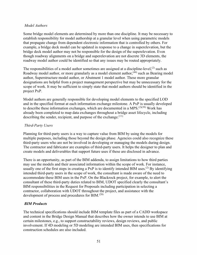
51
Model Authors
Some bridge model elements are determined by more than one discipline. It may be necessary to establish responsibility for model authorship at a granular level when using parametric models that propagate change from dependent electronic information that is controlled by others. For example, a bridge deck model can be updated in response to a change in superelevation, but the bridge deck model author may not be responsible for the design of the superelevation. Even though roadway alignments on a bridge and superelevation are not discrete 3D elements, the roadway model author could be identified so that any issues may be routed appropriately.
The responsibilities of a model author sometimes are assigned at a discipline-level,(2) such as Roadway model author, or more granularly as a model element author,(44) such as Bearing model author, Superstructure model author, or Abutment 1 model author. These more granular designations are helpful from a project management perspective but may be unnecessary for the scope of work. It may be sufficient to simply state that model authors should be identified in the project PxP.
Model authors are generally responsible for developing model elements to the specified LOD and in the specified format at each information exchange milestone. A PxP is usually developed to describe these information exchanges, which are documented in a MPS.(2)(39) Work has already been completed to map data exchanges throughout a bridge asset lifecycle, including describing the sender, recipient, and purpose of the exchange.(11)
Third-Party Users
Planning for third-party users is a way to capture value from BIM by using the models for multiple purposes, including those beyond the design phase. Agencies could also recognize these third-party users who are not be involved in developing or managing the models during design. The contractor and fabricator are examples of third-party users. It helps the designer to plan and create models and deliverables that support future uses if these are disclosed in advance.
There is an opportunity, as part of the BIM addenda, to assign limitations to how third parties may use the models and their associated information within the scope of work. For instance, usually one of the first steps in creating a PxP is to identify intended BIM uses.(2) By identifying intended third-party users in the scope of work, the consultant is made aware of the need to accommodate these BIM uses in the PxP. On the Blackrock project, for example, to alert the consultant of these third-party duties related to BIM, UDOT specified clearly the consultant’s BIM responsibilities in the Request for Proposals including participation in selecting a contractor, collaboration with UDOT throughout the project, and assistance with the development of process and procedures for BIM.(20)
BIM Products
The technical specifications should include BIM template files as part of a CADD workspace and content in the Bridge Design Manual that describes how the owner intends to use BIM at certain milestones, e.g., to support constructability reviews, design reviews, and public involvement. If 4D modeling or 5D modeling are intended BIM uses, then specifications for construction schedules are also included.

52
The collaborative nature of BIM is such that professionals rely on digital information provided (and often managed and controlled) by others; the technical specifications could include a means by which the recipient can validate the information. Checklists, or simply clear instructions to determine whether the digital data meets the specifications, are ways agencies could implement validation. One of the intentions behind the IFC Bridge Design to Construction Information Exchange (U.S.) is that it provides a machine-readable specification to validate the information provided for construction.
The amount of detail needed to specify the BIM deliverables typically depends on the amount of detail in the reference standards. For example, the Kosciuszko Bridge project statement of work(43) included provisions on deliverables specifying that the design-builder not only develop, maintain, and provide all CADD files to prepare contract plans but also perform all tasks to prepare and maintain 3D/4D/5D models, 3D animation, and 3D schedule simulations. The work performed would produce a visualization of the design and construction sequence and a method to evaluate and monitor construction operation and to track progress and payment.(43)
The process of creating the PxP can be used to resolve the details of the information exchanges and the overall BIM data structure, such as:
• The number of models and how they are partitioned. • The content and format of each model. • How the models are aggregated into a federated model. • How and when the models are shared among stakeholders. • The precedence of models when there is more than one model that contains information
about bridge systems or elements. • The relationship between the 3D models and the 2D drawings and other outputs (such as
videos, images, and so on).
Construction Specifications
The use of digital data, particularly 3D models from BIM, has resulted in some State transportation agencies modifying sections of their standard specifications. The voluntary and non-binding AASHTO Guide Specifications for Highway Construction complement the binding AASHTO LRFD Bridge Construction Specifications (23 CFR 625.4(b)(2)), it provides helpful references to states for developing construction specifications for BIM projects. (45) This section of this report includes additional suggestions on specifications for BIM projects for agencies to consider.
Partnering in BIM Projects
Using Partnering to establish a framework for resolving BIM-related issues, including data exchange, should be considered when drafting construction specifications.
When one party is less capable with BIM than the other, the information in BIM is less accessible to that party and it may feel at a disadvantage. Formal Partnering may be beneficial for projects using BIM as a way to resolve any misunderstanding that may arise from parties

53
having widely different BIM capabilities. UDOT used Partnering on the SR-20 project,(53) which was completed successfully, ahead of schedule.(24)
Electronic Documents and Digital Signatures
The use of electronic documents with digital signatures is increasing as part of the proliferation of e-Construction, a term that refers to paperless construction management practices. Updating specifications to accommodate using digital and electronic documents and signatures is being considered by State DOTs. For example, the Florida DOT has modified its specifications through a special provision to clearly specify that signatures executed electronically by parties have the same force and effect as written signatures. This special provision also states that all persons normally signing paper documents need to have access to the collaboration site where electronic documents reside, need to be identified during the preconstruction conference, and need to acquire digital signature certificates.(49)
Scope Validation
In the case study in chapter 2, the FHWA research team found that there was a learning curve for the contractor to become comfortable with the models received from the owner, which could lead to subsequent scope-related conflicts. The Scope Validation framework could be useful while the industry raises its level of capability with BIM for bridges and structures. For example, Virginia DOT uses a Scope Validation in design-build, specifically for Differing Site Conditions.(50) (51) The specification provides a limited duration to identify issues. Virginia DOT specifies a thorough review and comparison performed by design-builder on all of contract documents including the Request for Proposal and the Proposal to check and confirm proposed design concept and to identify errors, omissions, constructability problems, site conditions, or any other issues.(51) The specification also outlines a framework to resolve issues, and after the time period has elapsed, it allocates subsequent liabilities arising from scope issues to the design-builder.(51)
Exchange of Information and Communication
Construction specifications commonly describe the exchange of information and communication between the Contractor and the Engineer.(45) However, additional considerations are suggested by FHWA research team to be incorporated in construction specifications for BIM projects including BIM-related products, assigning precedence of BIM project documents, and resolving claims and disputes using BIM.
BIM-related Products—Plans and Working Drawings
Construction specifications typically identify information provided to the contractor and the contractor’s submittals, such as shop drawings and as-built records.(52) BIM-related products could be introduced as part of the information that the owner and the contractor deliver to one another.(52)
54
Agencies may consider how to include BIM-related products in their specifications such as:
• An initial set of models (a federated model and dependent discipline models) and their associated metadata (such as Model Inventories and reference standards) provided by the owner with the contract plans.
• The contractor’s PxP as an early submittal prior to mobilization. • Any construction simulations or visualizations provided by the contractor that the owner
uses to monitor progress or communicate with the public. • Shop models (if allowed). • The as-built or record model and information submittals, including the reference
standards for these deliverables.
Coordinating BIM Project Documents
When assigning the precedence of BIM project documents, separately assigning the order of precedence for information and for dimensions is suggested. The construction specifications should provide information on how to resolve ambiguities or conflicting information. With model deliverables, the contractor can dimension and query the model at will to extract information for bidding or construction. The Model Inventory may designate the LOD of the model elements and inform the contractor of how the model information may be reliably used.
For example, in its special provision for the SR-20 project, UDOT used the following order of precedence:(53)
The governing ranking in case of a discrepancy is: Dimensions Information
1. Model 2. Plans 3. Calculated 4. Scaled
1. Model 2. Special Provisions 3. Plans 4. Supplemental Specifications 5. Supplemental Drawings 6. Measurement and Payment 7. Standard Specifications 8. Standard Drawings (53)
In construction specifications, it is important to clearly address whether a dimension scaled in the model would be considered “Model” (first order of precedence in the example) or “Scaled” (fourth order of precedence in the example). For instance, since an electronic file can contain saved views or sheet models with annotated dimensions, the standard order of precedence could apply if models are incorporated into the description of “Plans” and any dimensions the contractor makes in the model are described as either “Scaled” or “Calculated.”
Using BIM in Resolving Claims and Disputes
BIM may be used in the process of resolving claims and disputes.(44) The models may be used to demonstrate a possible conflict or to produce construction simulations that demonstrate the

55
impact of an event by comparing the planned versus actual progression. Construction specifications could include information or procedures to potentially allow for the use of BIM (models and outputs) in resolving claims and disputes. The Partnering agreement could be the appropriate document.
Construction Simulations
If BIM is used to create construction simulations (also known as 4D or 5D models), then electronic schedules are critical, and should be identified in construction specifications. The minimum task technical information needed to create construction simulations are the unique task ID, start date, and end date. 5D models also need a cost field for each task. Most software for generating 4D and 5D models can read a range of schedule formats, including proprietary formats (Microsoft Project® and Primavera®) as well as comma separated values files and spreadsheets.

56
CHAPTER 5 AASHTOWARE BRD TO IFC EXCHANGE UTILITY
Introduction
A critical aspect of implementing any neutral data exchange format is verification and testing through common industry tools. This chapter describes a utility application and accompanying software components that have been created to convert data from AASHTOWare Bridge Design (BrD)/Bridge Rating (BrR) into IFC format based on the FHWA Bridge Design-to-Construction Information Exchange (U.S).(54) This is a non-commercial software program for proof of concept which is available to States for additional testing and use. This utility enables a wide range of existing software to use the transformed data for visualization, fabrication, structural analysis, and construction. The software exchanges data automatically, reducing or eliminating the need to reconstruct models for such bridges when used in other software. At this time, the software only exchanges information from AASHTOWare into the IFC format. It could be possible to import data from design applications into AASHTOWare, but that exchange has not yet been developed.
AASHTOWare BrD and BrR (55) are Windows applications used by transportation agencies to design and provide load rating of bridges and report results of structural analysis. IFC (56) is a software format supported by many software applications used for 3D design in the construction industry.
Data Models
AASHTOWare BrD and Industry Foundation Classes organize data in similar ways. The organization is also consistent with many other bridge applications.
AASHTOWare Bridge Data Model
The major data structure of BrD is a single project object that is decomposed into a hierarchy of structures and contains a set of definitions developed in AASHTOWare BrD, shapes, and materials. Figure 25 illustrates this data structure, where:
• Structures describes overall systems (e.g., deck, superstructure, substructure) and arecomposed of physical elements or assemblies (e.g., girder segments, cross frames,stiffener plates) that may be positioned along a referenced alignment curve. Each elementmay consist of multiple alternate configurations, each of which may reference a specificBrD definition and apply specific parameters. There is notion of a single “current”alternate and an optional “existing” alternate.
• Definitions in AASHTOWare BrD data model may consist of components, eachdescribing a specific physical part, which may reference a common shape (e.g., 2D crosssection) and a common material.
• Shapes may describe parametrized cross sections (e.g., Steel I-Shape, Precast BoxShape), for which the outer contour (and potential inner contours) of the cross sectionmay be derived by parameters (e.g., web height, flange thickness, fillet radius).
• Materials may describe the class and mechanical properties of materials used forcomponents (e.g., concrete, structural steel, timber).
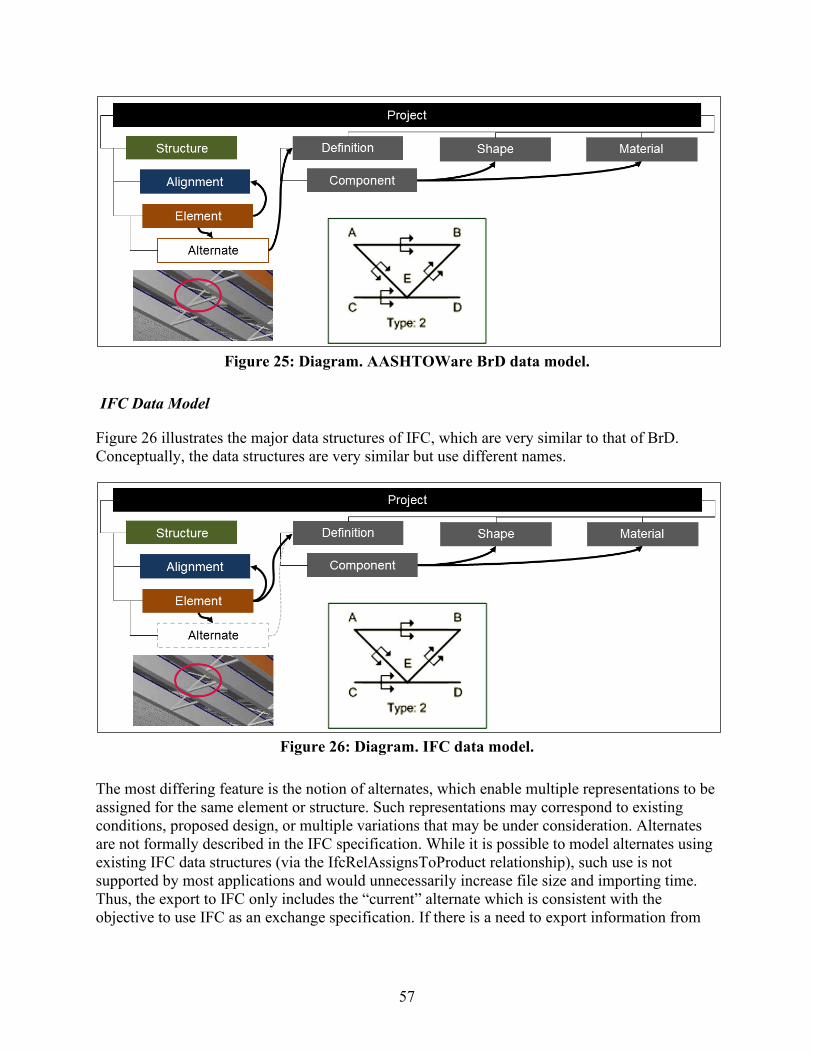
57
Figure 25: Diagram. AASHTOWare BrD data model.
IFC Data Model
Figure 26 illustrates the major data structures of IFC, which are very similar to that of BrD. Conceptually, the data structures are very similar but use different names.
Figure 26: Diagram. IFC data model.
The most differing feature is the notion of alternates, which enable multiple representations to be assigned for the same element or structure. Such representations may correspond to existing conditions, proposed design, or multiple variations that may be under consideration. Alternates are not formally described in the IFC specification. While it is possible to model alternates using existing IFC data structures (via the IfcRelAssignsToProduct relationship), such use is not supported by most applications and would unnecessarily increase file size and importing time. Thus, the export to IFC only includes the “current” alternate which is consistent with the objective to use IFC as an exchange specification. If there is a need to export information from
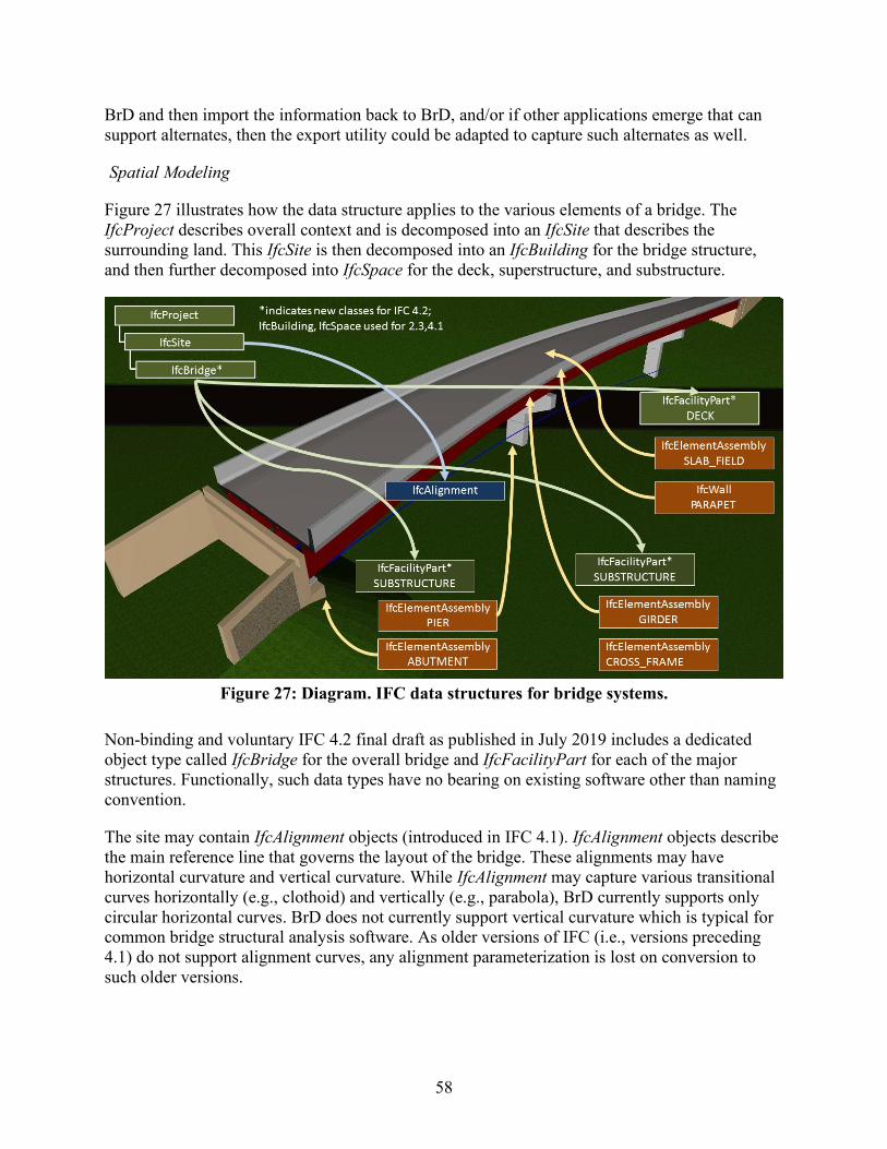
58
BrD and then import the information back to BrD, and/or if other applications emerge that can support alternates, then the export utility could be adapted to capture such alternates as well.
Spatial Modeling
Figure 27 illustrates how the data structure applies to the various elements of a bridge. The IfcProject describes overall context and is decomposed into an IfcSite that describes the surrounding land. This IfcSite is then decomposed into an IfcBuilding for the bridge structure, and then further decomposed into IfcSpace for the deck, superstructure, and substructure.
Figure 27: Diagram. IFC data structures for bridge systems.
Non-binding and voluntary IFC 4.2 final draft as published in July 2019 includes a dedicated object type called IfcBridge for the overall bridge and IfcFacilityPart for each of the major structures. Functionally, such data types have no bearing on existing software other than naming convention.
The site may contain IfcAlignment objects (introduced in IFC 4.1). IfcAlignment objects describe the main reference line that governs the layout of the bridge. These alignments may have horizontal curvature and vertical curvature. While IfcAlignment may capture various transitional curves horizontally (e.g., clothoid) and vertically (e.g., parabola), BrD currently supports only circular horizontal curves. BrD does not currently support vertical curvature which is typical for common bridge structural analysis software. As older versions of IFC (i.e., versions preceding 4.1) do not support alignment curves, any alignment parameterization is lost on conversion to such older versions.
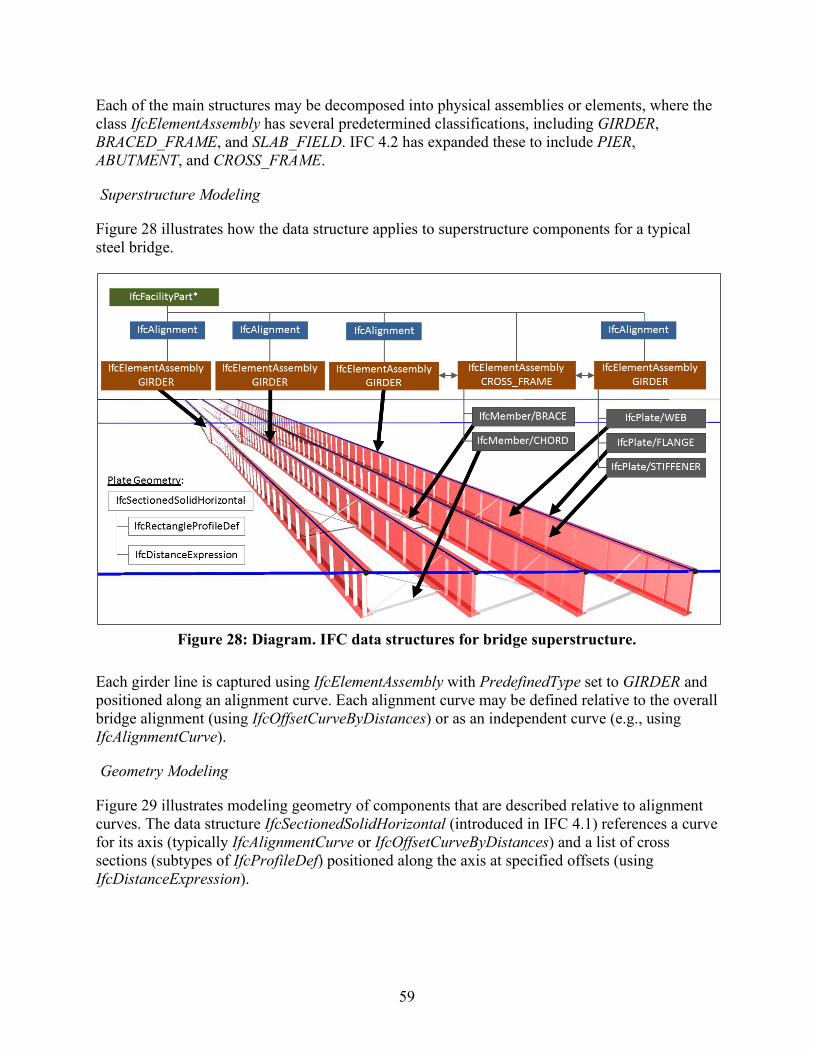
59
Each of the main structures may be decomposed into physical assemblies or elements, where the class IfcElementAssembly has several predetermined classifications, including GIRDER, BRACED_FRAME, and SLAB_FIELD. IFC 4.2 has expanded these to include PIER, ABUTMENT, and CROSS_FRAME.
Superstructure Modeling
Figure 28 illustrates how the data structure applies to superstructure components for a typical steel bridge.
Figure 28: Diagram. IFC data structures for bridge superstructure.
Each girder line is captured using IfcElementAssembly with PredefinedType set to GIRDER and positioned along an alignment curve. Each alignment curve may be defined relative to the overall bridge alignment (using IfcOffsetCurveByDistances) or as an independent curve (e.g., using IfcAlignmentCurve).
Geometry Modeling
Figure 29 illustrates modeling geometry of components that are described relative to alignment curves. The data structure IfcSectionedSolidHorizontal (introduced in IFC 4.1) references a curve for its axis (typically IfcAlignmentCurve or IfcOffsetCurveByDistances) and a list of cross sections (subtypes of IfcProfileDef) positioned along the axis at specified offsets (using IfcDistanceExpression).
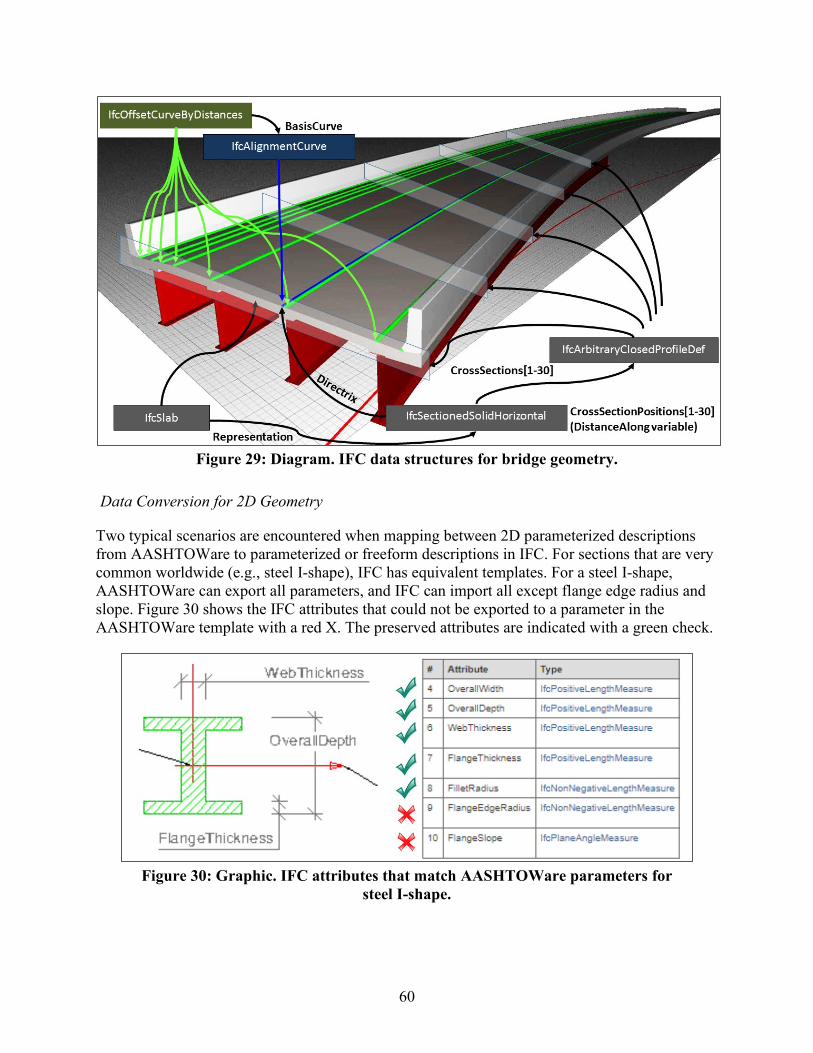
60
Figure 29: Diagram. IFC data structures for bridge geometry.
Data Conversion for 2D Geometry
Two typical scenarios are encountered when mapping between 2D parameterized descriptions from AASHTOWare to parameterized or freeform descriptions in IFC. For sections that are very common worldwide (e.g., steel I-shape), IFC has equivalent templates. For a steel I-shape, AASHTOWare can export all parameters, and IFC can import all except flange edge radius and slope. Figure 30 shows the IFC attributes that could not be exported to a parameter in the AASHTOWare template with a red X. The preserved attributes are indicated with a green check.
Figure 30: Graphic. IFC attributes that match AASHTOWare parameters for
steel I-shape.
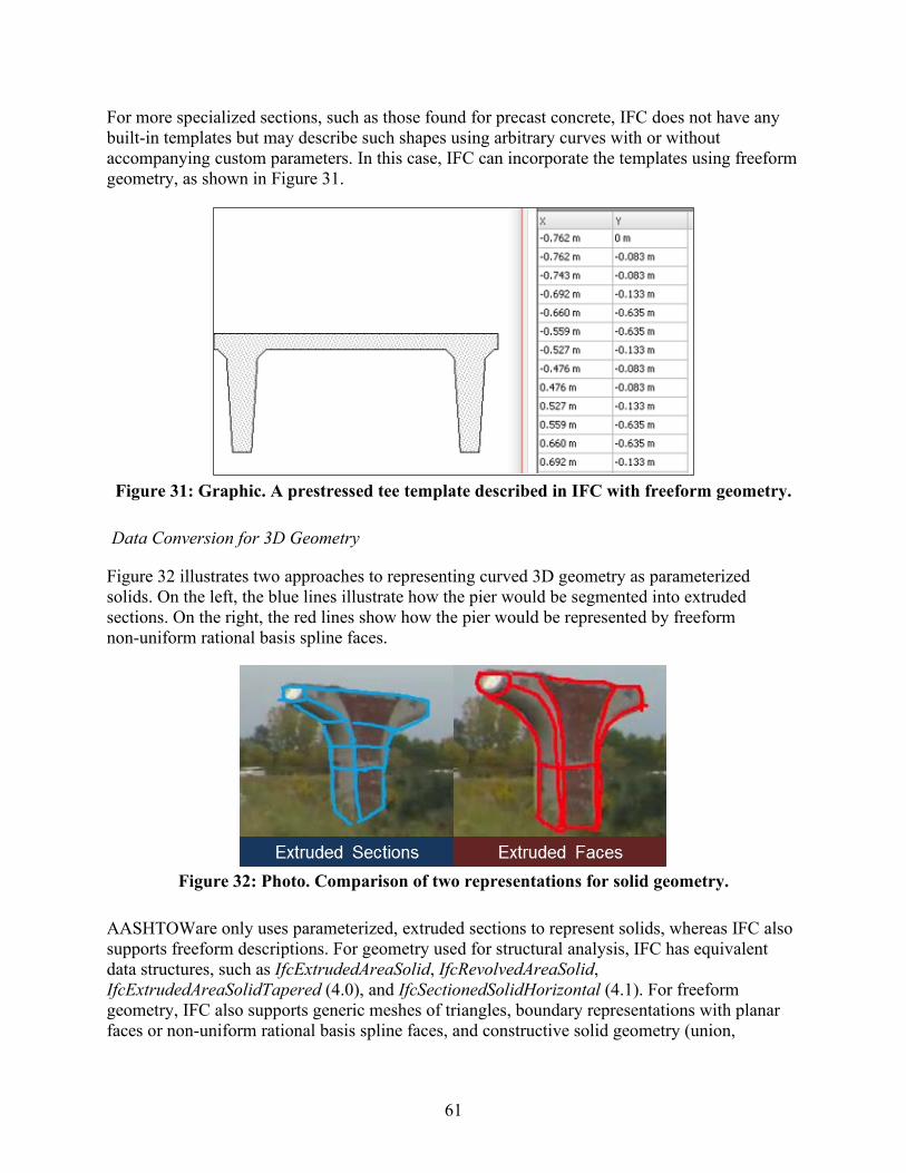
61
For more specialized sections, such as those found for precast concrete, IFC does not have any built-in templates but may describe such shapes using arbitrary curves with or without accompanying custom parameters. In this case, IFC can incorporate the templates using freeform geometry, as shown in Figure 31.
Figure 31: Graphic. A prestressed tee template described in IFC with freeform geometry.
Data Conversion for 3D Geometry
Figure 32 illustrates two approaches to representing curved 3D geometry as parameterized solids. On the left, the blue lines illustrate how the pier would be segmented into extruded sections. On the right, the red lines show how the pier would be represented by freeform non-uniform rational basis spline faces.
Figure 32: Photo. Comparison of two representations for solid geometry.
AASHTOWare only uses parameterized, extruded sections to represent solids, whereas IFC also supports freeform descriptions. For geometry used for structural analysis, IFC has equivalent data structures, such as IfcExtrudedAreaSolid, IfcRevolvedAreaSolid, IfcExtrudedAreaSolidTapered (4.0), and IfcSectionedSolidHorizontal (4.1). For freeform geometry, IFC also supports generic meshes of triangles, boundary representations with planar faces or non-uniform rational basis spline faces, and constructive solid geometry (union,
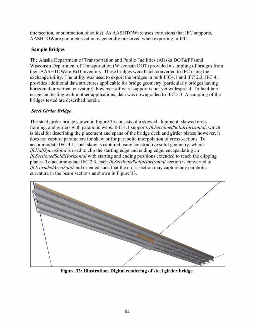
62
intersection, or subtraction of solids). As AASHTOWare uses extrusions that IFC supports, AASHTOWare parameterization is generally preserved when exporting to IFC.
Sample Bridges
The Alaska Department of Transportation and Public Facilities (Alaska DOT&PF) and Wisconsin Department of Transportation (Wisconsin DOT) provided a sampling of bridges from their AASHTOWare BrD inventory. These bridges were batch converted to IFC using the exchange utility. The utility was used to export the bridges in both IFC4.1 and IFC 2.3. IFC 4.1 provides additional data structures applicable for bridge geometry (particularly bridges having horizontal or vertical curvature), however software support is not yet widespread. To facilitate usage and testing within other applications, data was downgraded to IFC 2.3. A sampling of the bridges tested are described herein.
Steel Girder Bridge
The steel girder bridge shown in Figure 33 consists of a skewed alignment, skewed cross framing, and girders with parabolic webs. IFC 4.1 supports IfcSectionedSolidHorizontal, which is ideal for describing the placement and spans of the bridge deck and girder plates; however, it does not capture parameters for skew or for parabolic interpolation of cross sections. To accommodate IFC 4.1, such skew is captured using constructive solid geometry, where IfcHalfSpaceSolid is used to clip the starting edge and ending edge, encapsulating an IfcSectionedSoldiHorizontal with starting and ending positions extended to reach the clipping planes. To accommodate IFC 2.3, each IfcSectionedSolidHorizontal section is converted to IfcExtrudedAreaSolid and oriented such that the cross section may capture any parabolic curvature in the beam sections as shown in Figure 33.
Figure 33: Illustration. Digital rendering of steel girder bridge.
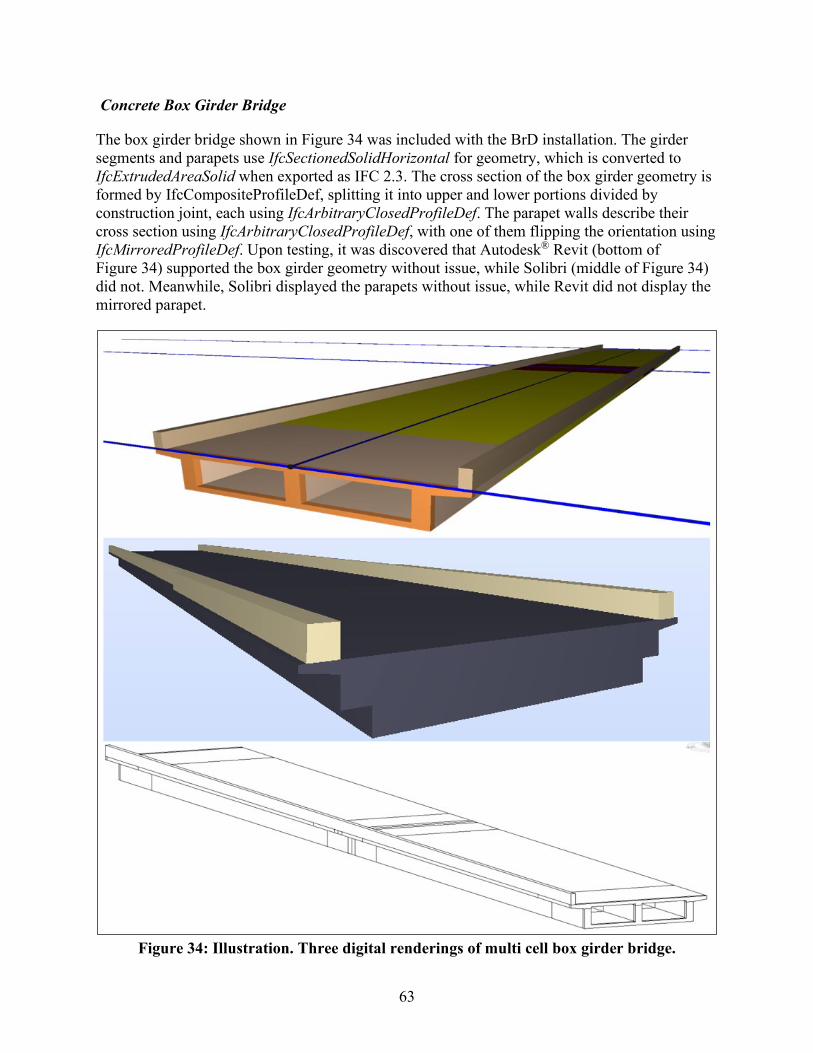
63
Concrete Box Girder Bridge
The box girder bridge shown in Figure 34 was included with the BrD installation. The girder segments and parapets use IfcSectionedSolidHorizontal for geometry, which is converted to IfcExtrudedAreaSolid when exported as IFC 2.3. The cross section of the box girder geometry is formed by IfcCompositeProfileDef, splitting it into upper and lower portions divided by construction joint, each using IfcArbitraryClosedProfileDef. The parapet walls describe their cross section using IfcArbitraryClosedProfileDef, with one of them flipping the orientation using IfcMirroredProfileDef. Upon testing, it was discovered that Autodesk® Revit (bottom of Figure 34) supported the box girder geometry without issue, while Solibri (middle of Figure 34) did not. Meanwhile, Solibri displayed the parapets without issue, while Revit did not display the mirrored parapet.
Figure 34: Illustration. Three digital renderings of multi cell box girder bridge.
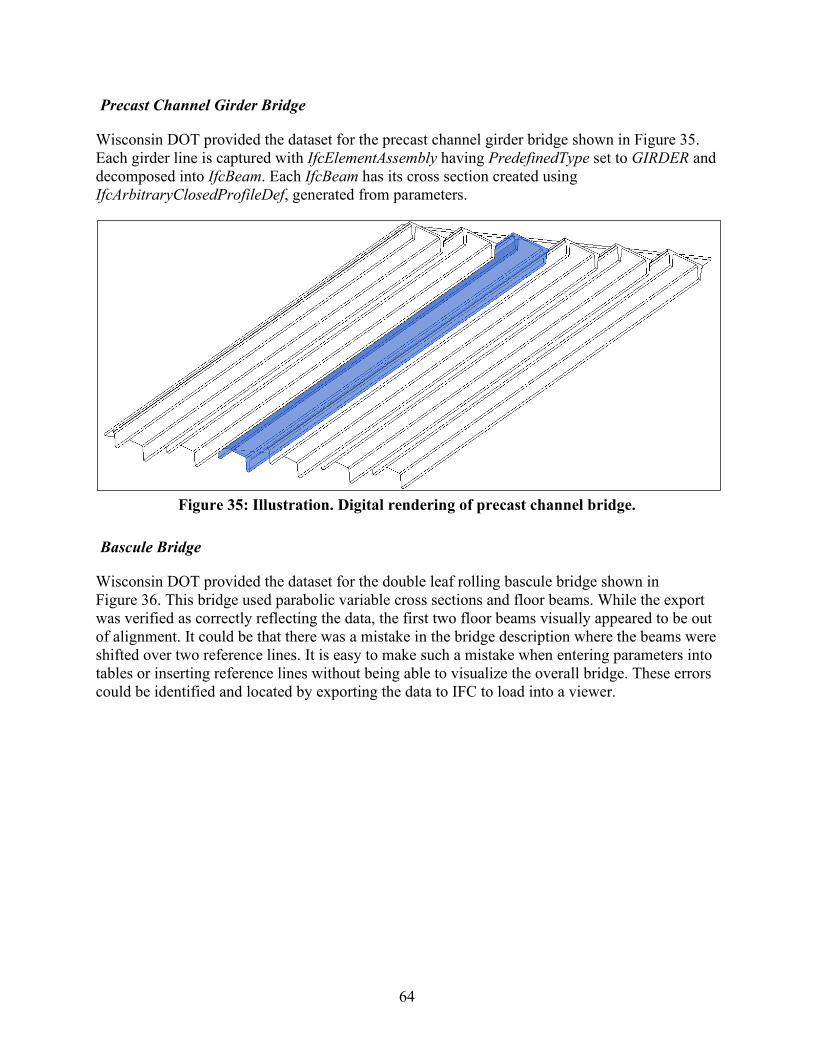
64
Precast Channel Girder Bridge
Wisconsin DOT provided the dataset for the precast channel girder bridge shown in Figure 35. Each girder line is captured with IfcElementAssembly having PredefinedType set to GIRDER and decomposed into IfcBeam. Each IfcBeam has its cross section created using IfcArbitraryClosedProfileDef, generated from parameters.
Figure 35: Illustration. Digital rendering of precast channel bridge.
Bascule Bridge
Wisconsin DOT provided the dataset for the double leaf rolling bascule bridge shown in Figure 36. This bridge used parabolic variable cross sections and floor beams. While the export was verified as correctly reflecting the data, the first two floor beams visually appeared to be out of alignment. It could be that there was a mistake in the bridge description where the beams were shifted over two reference lines. It is easy to make such a mistake when entering parameters into tables or inserting reference lines without being able to visualize the overall bridge. These errors could be identified and located by exporting the data to IFC to load into a viewer.
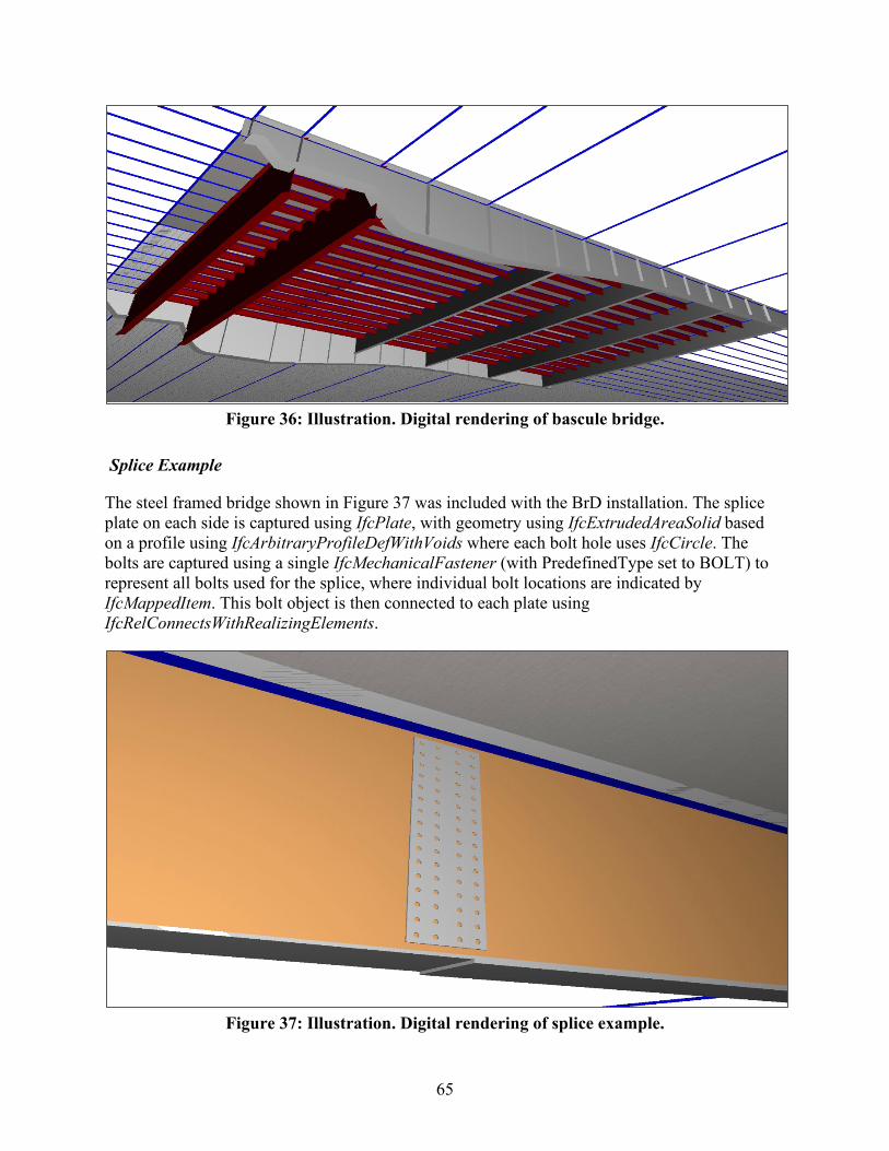
65
Figure 36: Illustration. Digital rendering of bascule bridge.
Splice Example
The steel framed bridge shown in Figure 37 was included with the BrD installation. The splice plate on each side is captured using IfcPlate, with geometry using IfcExtrudedAreaSolid based on a profile using IfcArbitraryProfileDefWithVoids where each bolt hole uses IfcCircle. The bolts are captured using a single IfcMechanicalFastener (with PredefinedType set to BOLT) to represent all bolts used for the splice, where individual bolt locations are indicated by IfcMappedItem. This bolt object is then connected to each plate using IfcRelConnectsWithRealizingElements.
Figure 37: Illustration. Digital rendering of splice example.
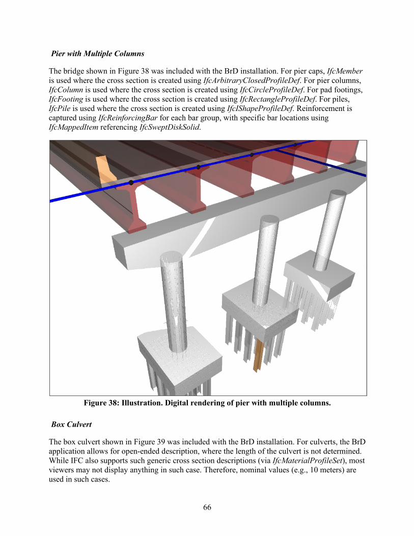
66
Pier with Multiple Columns
The bridge shown in Figure 38 was included with the BrD installation. For pier caps, IfcMember is used where the cross section is created using IfcArbitraryClosedProfileDef. For pier columns, IfcColumn is used where the cross section is created using IfcCircleProfileDef. For pad footings, IfcFooting is used where the cross section is created using IfcRectangleProfileDef. For piles, IfcPile is used where the cross section is created using IfcIShapeProfileDef. Reinforcement is captured using IfcReinforcingBar for each bar group, with specific bar locations using IfcMappedItem referencing IfcSweptDiskSolid.
Figure 38: Illustration. Digital rendering of pier with multiple columns.
Box Culvert
The box culvert shown in Figure 39 was included with the BrD installation. For culverts, the BrD application allows for open-ended description, where the length of the culvert is not determined. While IFC also supports such generic cross section descriptions (via IfcMaterialProfileSet), most viewers may not display anything in such case. Therefore, nominal values (e.g., 10 meters) are used in such cases.
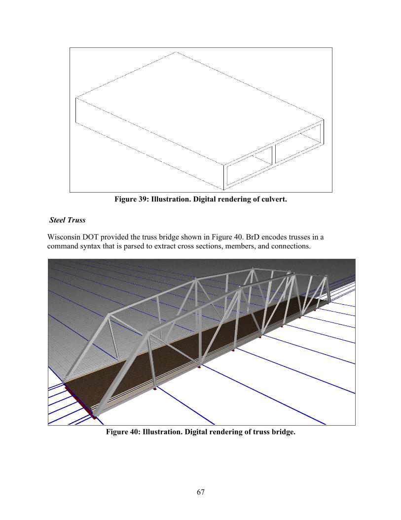
67
Figure 39: Illustration. Digital rendering of culvert.
Steel Truss
Wisconsin DOT provided the truss bridge shown in Figure 40. BrD encodes trusses in a command syntax that is parsed to extract cross sections, members, and connections.
Figure 40: Illustration. Digital rendering of truss bridge.
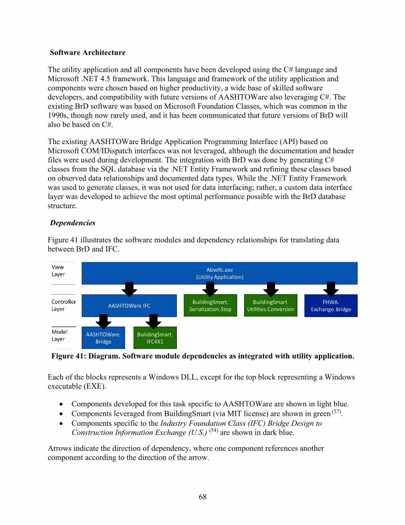
68
Software Architecture
The utility application and all components have been developed using the C# language and Microsoft .NET 4.5 framework. This language and framework of the utility application and components were chosen based on higher productivity, a wide base of skilled software developers, and compatibility with future versions of AASHTOWare also leveraging C#. The existing BrD software was based on Microsoft Foundation Classes, which was common in the 1990s, though now rarely used, and it has been communicated that future versions of BrD will also be based on C#.
The existing AASHTOWare Bridge Application Programming Interface (API) based on Microsoft COM/IDispatch interfaces was not leveraged, although the documentation and header files were used during development. The integration with BrD was done by generating C# classes from the SQL database via the .NET Entity Framework and refining these classes based on observed data relationships and documented data types. While the .NET Entity Framework was used to generate classes, it was not used for data interfacing; rather, a custom data interface layer was developed to achieve the most optimal performance possible with the BrD database structure.
Dependencies
Figure 41 illustrates the software modules and dependency relationships for translating data between BrD and IFC.
Figure 41: Diagram. Software module dependencies as integrated with utility application.
Each of the blocks represents a Windows DLL, except for the top block representing a Windows executable (EXE).
• Components developed for this task specific to AASHTOWare are shown in light blue. • Components leveraged from BuildingSmart (via MIT license) are shown in green (57). • Components specific to the Industry Foundation Class (IFC) Bridge Design to
Construction Information Exchange (U.S.) (54) are shown in dark blue.
Arrows indicate the direction of dependency, where one component references another component according to the direction of the arrow.
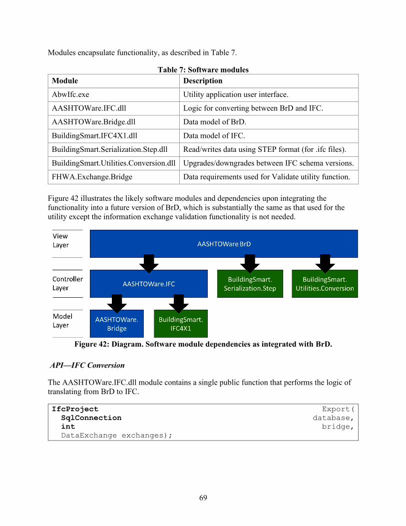
69
Modules encapsulate functionality, as described in Table 7.
Table 7: Software modules Module Description
AbwIfc.exe Utility application user interface.
AASHTOWare.IFC.dll Logic for converting between BrD and IFC.
AASHTOWare.Bridge.dll Data model of BrD.
BuildingSmart.IFC4X1.dll Data model of IFC.
BuildingSmart.Serialization.Step.dll Read/writes data using STEP format (for .ifc files).
BuildingSmart.Utilities.Conversion.dll Upgrades/downgrades between IFC schema versions.
FHWA.Exchange.Bridge Data requirements used for Validate utility function.
Figure 42 illustrates the likely software modules and dependencies upon integrating the functionality into a future version of BrD, which is substantially the same as that used for the utility except the information exchange validation functionality is not needed.
Figure 42: Diagram. Software module dependencies as integrated with BrD.
API—IFC Conversion
The AASHTOWare.IFC.dll module contains a single public function that performs the logic of translating from BrD to IFC.
IfcProject Export( SqlConnection database, int bridge, DataExchange exchanges);
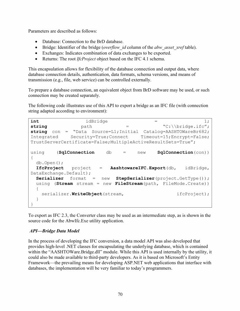
70
Parameters are described as follows:
• Database: Connection to the BrD database. • Bridge: Identifier of the bridge (overflow_id column of the abw_asset_xref table). • Exchanges: Indicates combination of data exchanges to be exported. • Returns: The root IfcProject object based on the IFC 4.1 schema.
This encapsulation allows for flexibility of the database connection and output data, where database connection details, authentication, data formats, schema versions, and means of transmission (e.g., file, web service) can be controlled externally.
To prepare a database connection, an equivalent object from BrD software may be used, or such connection may be created separately.
The following code illustrates use of this API to export a bridge as an IFC file (with connection string adapted according to environment):
To export as IFC 2.3, the Converter class may be used as an intermediate step, as is shown in the source code for the AbwIfc.Exe utility application.
API—Bridge Data Model
In the process of developing the IFC conversion, a data model API was also developed that provides high-level .NET classes for encapsulating the underlying database, which is contained within the “AASHTOWare.Bridge.dll” module. While this API is used internally by the utility, it could also be made available to third-party developers. As it is based on Microsoft’s Entity Framework—the prevailing means for developing ASP.NET web applications that interface with databases, the implementation will be very familiar to today’s programmers.
int idBridge = 1; string path = “C:\\bridge.ifc”; string con = “Data Source=L1;Initial Catalog=AASHTOWareBr682; Integrated Security=True;Connect Timeout=15;Encrypt=False; TrustServerCertificate=False;MultipleActiveResultSets=True”; using (SqlConnection db = new SqlConnection(con)) { db.Open(); IfcProject project = AashtowareIFC.Export(db, idBridge, DataExchange.Default); Serializer format = new StepSerializer(project.GetType()); using (Stream stream = new FileStream(path, FileMode.Create)) { serializer.WriteObject(stream, ifcProject); } }
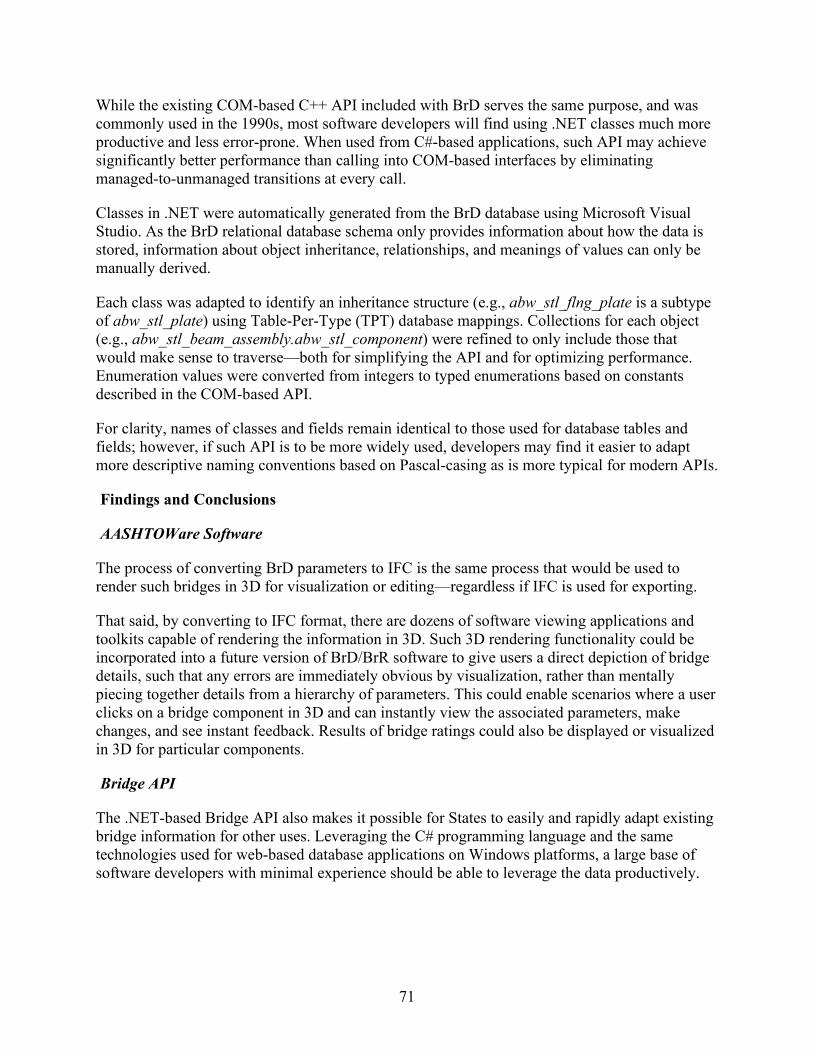
71
While the existing COM-based C++ API included with BrD serves the same purpose, and was commonly used in the 1990s, most software developers will find using .NET classes much more productive and less error-prone. When used from C#-based applications, such API may achieve significantly better performance than calling into COM-based interfaces by eliminating managed-to-unmanaged transitions at every call.
Classes in .NET were automatically generated from the BrD database using Microsoft Visual Studio. As the BrD relational database schema only provides information about how the data is stored, information about object inheritance, relationships, and meanings of values can only be manually derived.
Each class was adapted to identify an inheritance structure (e.g., abw_stl_flng_plate is a subtype of abw_stl_plate) using Table-Per-Type (TPT) database mappings. Collections for each object (e.g., abw_stl_beam_assembly.abw_stl_component) were refined to only include those that would make sense to traverse—both for simplifying the API and for optimizing performance. Enumeration values were converted from integers to typed enumerations based on constants described in the COM-based API.
For clarity, names of classes and fields remain identical to those used for database tables and fields; however, if such API is to be more widely used, developers may find it easier to adapt more descriptive naming conventions based on Pascal-casing as is more typical for modern APIs.
Findings and Conclusions
AASHTOWare Software
The process of converting BrD parameters to IFC is the same process that would be used to render such bridges in 3D for visualization or editing—regardless if IFC is used for exporting.
That said, by converting to IFC format, there are dozens of software viewing applications and toolkits capable of rendering the information in 3D. Such 3D rendering functionality could be incorporated into a future version of BrD/BrR software to give users a direct depiction of bridge details, such that any errors are immediately obvious by visualization, rather than mentally piecing together details from a hierarchy of parameters. This could enable scenarios where a user clicks on a bridge component in 3D and can instantly view the associated parameters, make changes, and see instant feedback. Results of bridge ratings could also be displayed or visualized in 3D for particular components.
Bridge API
The .NET-based Bridge API also makes it possible for States to easily and rapidly adapt existing bridge information for other uses. Leveraging the C# programming language and the same technologies used for web-based database applications on Windows platforms, a large base of software developers with minimal experience should be able to leverage the data productively.

72
Data Needs
Working with bridge models in parallel has illustrated the importance of precise data requirements, testing with a wide range of representative bridge models, and the need to validate software before assuming it can meet interoperability needs of users.
In the initial phases of this effort, it was found that bugs in data exporting were ignored by some applications but tolerated by others. In instances when data would not load or present correctly in some applications, there was typically very limited feedback, if any, indicating error conditions. However, upon running exported files through testing tools (e.g., gtds.buildingsmart.org), specific errors were pinpointed, and once fixed, then loaded correctly.
This experience has shown that if something is ambiguous or not widely used and tested, there is an increased chance of errors in interoperability. For example, descriptions used for composite and mirrored cross sections are useful for bridges, although are not as applicable for buildings, which may explain why such descriptions have not been widely tested in implementations. As discussed in this report, there were certain instances where the same bridge file appeared differently in Revit and Solibri.
Establishing specific minimal data needs for bridges and validating exported models against such lists provide a basis to inform users and vendors whether a software has sufficient capabilities for interoperability of specific use cases (e.g., to build a bridge, to complete a structural analysis of a bridge, or other purpose).(40) The goal is to give users high confidence when moving data from one application to another that both the sending application and receiving application can work for the intended use.
Data Exporting for Construction
Out of 840 database tables within AASHTOWare bridge software, 416 have applicability for construction (e.g., describe components, connections, geometry, and materials). Of these, 99 tables were proposed to be within scope for this project, with the caveat that specific tables may vary upon further investigation while implementing. Based on data present in bridge models provided from States, which was unknown initially, 264 database tables were implemented—approximately 250 percent of the scope as proposed.
As newer functionality provided in IFC 4.1 is not yet widely supported by software vendors, an additional step was undertaken to add functionality to automatically convert the exported data structures into IFC 2.3 format, which included various geometric conversion routines. This was then tested to run successfully on MicroStation, Revit, and Solibri.
For the future, it would also be possible to capture the remaining database tables useful for construction for some of the less common scenarios and/or tables used for structural analysis. The tables implemented support all data within the sample models provided, which may be sufficient for most scenarios encountered.

73
Data Importing for Structural Analysis
While exporting data from AASHTOWare into design applications may be useful as a basis for matching the design of existing bridges or performing maintenance on bridges, such information only captures data relevant to structural behavior and leaves out other data that are necessary for construction, such as vertical curvature, terrain, utilities, drainage, architectural features, and more complex geometry often seen in modern bridge designs. As the purpose of AASHTOWare bridge software is for structural analysis, this is to be expected.
Importing bridges from 3D design software into AASHTOWare for bridge rating purposes may also be of interest. As AASHTOWare software is based on a fixed set of templates, and 3D design software is generally free form (with or without templates that may be dynamically established), such reverse conversion includes more sophisticated algorithms for pattern matching. Such reverse conversion also includes some amount of engineering judgment (or providing users control over such judgment) to make sufficient approximations of how free-form geometry is best converted into analytical forms. With export now functional, this now provides a basis such that any IFC data exported from BrD would be able to be imported back the same, and other components and geometry encountered may be converted into the most suitable forms.
Summary
The utility developed in this research provides access to data stored in AASHTOWare databases at transportation agencies, which may not only be leveraged by users exporting to design applications, but also to accelerate bridge data interoperability with other software. By leveraging software commonly used to read and write bridge models, users have a basis to apply data standards directly to sample models and are in a position to more clearly identify future data needs. If such bridge models are made available to the software community at large, this may also help accelerate support by other vendors and increase the likelihood of discovering errors before the software is released.

74
CHAPTER 6 IFC MODEL OF CASE STUDY BRIDGES
Introduction
A goal of this research was to apply the proposed IFC data exchange specification to common bridges constructed in the U.S. and determine what can be modeled effectively and suggest further development of this private, voluntary, and consensus-based standard. The three bridges from the UDOT case study project described in chapter 2 of this report were used to further test the Bridge Design-to-Construction Information Exchange (U.S.) MVD on modern bridges that are being specified for construction and fabrication. The extent of functionality with IFC-compliant models was investigated and results are provided herein.
Current Digital Models
UDOT’s designers produced models in Bentley® DGN format, along with exports to IFC and COLLADA™, which is a portmanteau of COLLAborative Design Activity. COLLADA™ is an open standard (ISO/PAS 17506:2012) XML schema for exchanging 3D digital assets.(58) This section describes what was found to be possible with current software tools using the models provided by automatically converting data for downstream use.
IFC Export
IFC files were exported for each bridge. The resulting data included a flat set of objects with tessellated geometry (Faceted BREP) that approximates general dimensions and contained style information providing color-coding for different component types. Figure 43 shows the resulting exported geometry.
Figure 43: Illustration. IFC export with tessellated geometry.
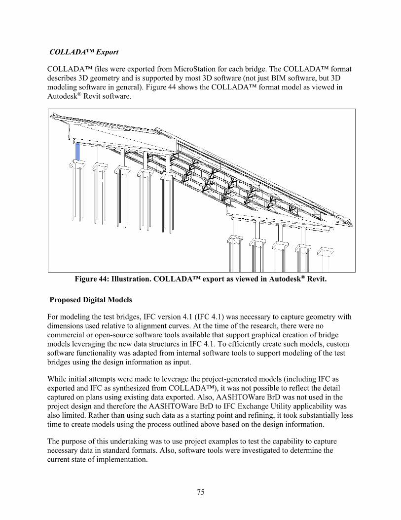
75
COLLADA™ Export
COLLADA™ files were exported from MicroStation for each bridge. The COLLADA™ format describes 3D geometry and is supported by most 3D software (not just BIM software, but 3D modeling software in general). Figure 44 shows the COLLADA™ format model as viewed in Autodesk® Revit software.
Figure 44: Illustration. COLLADA™ export as viewed in Autodesk® Revit.
Proposed Digital Models
For modeling the test bridges, IFC version 4.1 (IFC 4.1) was necessary to capture geometry with dimensions used relative to alignment curves. At the time of the research, there were no commercial or open-source software tools available that support graphical creation of bridge models leveraging the new data structures in IFC 4.1. To efficiently create such models, custom software functionality was adapted from internal software tools to support modeling of the test bridges using the design information as input.
While initial attempts were made to leverage the project-generated models (including IFC as exported and IFC as synthesized from COLLADA™), it was not possible to reflect the detail captured on plans using existing data exported. Also, AASHTOWare BrD was not used in the project design and therefore the AASHTOWare BrD to IFC Exchange Utility applicability was also limited. Rather than using such data as a starting point and refining, it took substantially less time to create models using the process outlined above based on the design information.
The purpose of this undertaking was to use project examples to test the capability to capture necessary data in standard formats. Also, software tools were investigated to determine the current state of implementation.

76
Within this section, references are made to IFC data structures and accompanying versions where applicable.
• IFC 4.2 was still in development during the research and the published version may be different to what is noted in this report. It contains new data structures for classification of bridge elements. Without any available software applications supporting these new data structures, custom software routines were developed to model the new data structures. An earlier draft of IFC 4.2 provided enhanced geometry supporting skew angles and parabolic sections, and parametric placement along spans and repetition intervals; however, such capabilities are not present in the latest final draft published in July 2019.
• IFC 4.1 was released in 2017. It contains new data structures for capturing alignment curves and solid geometry based on alignment curves. As of this date, there are still no known commercial applications available supporting IFC 4.1.
• IFC 4.0 was released in 2013. It contains new data structures for parametric geometry. While common software platforms support reading and writing IFC 4.0, the new data structures are still not widely supported.
• IFC 2.3 was released in 2008. The core framework and geometry are widely supported among most BIM applications. However, some data structures, particularly for structural analysis, are scarcely supported.
Where no version is indicated, the data structure is part of IFC 2.3. Historically, it has been observed that users encountered data using the released version of IFC before the release was widely available in commercial software. For purposes of this research, IFC 4.2 was used as a basis to illustrate what is possible. To facilitate usage within other applications, data was downgraded to IFC 2.3.
Structure Elements
Two types of structures were modeled as part of this demonstration project. The steel bridge (C1047) consists of westbound (left) and eastbound (right) structures shown in Figure 45, and the precast bridge (F881) is shown in Figure 46. Each is encapsulated as IfcBridge spatial structure, with the alignment using IfcAlignmentCurve with linear horizontal and linear vertical components.
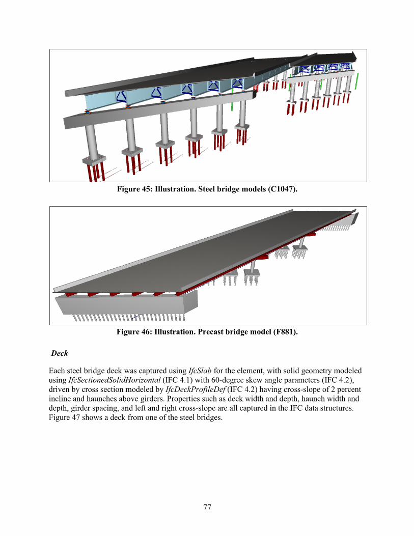
77
Figure 45: Illustration. Steel bridge models (C1047).
Figure 46: Illustration. Precast bridge model (F881).
Deck
Each steel bridge deck was captured using IfcSlab for the element, with solid geometry modeled using IfcSectionedSolidHorizontal (IFC 4.1) with 60-degree skew angle parameters (IFC 4.2), driven by cross section modeled by IfcDeckProfileDef (IFC 4.2) having cross-slope of 2 percent incline and haunches above girders. Properties such as deck width and depth, haunch width and depth, girder spacing, and left and right cross-slope are all captured in the IFC data structures. Figure 47 shows a deck from one of the steel bridges.
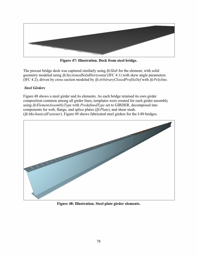
78
Figure 47: Illustration. Deck from steel bridge.
The precast bridge deck was captured similarly using IfcSlab for the element, with solid geometry modeled using IfcSectionedSolidHorizontal (IFC 4.1) with skew angle parameters (IFC 4.2), driven by cross section modeled by IfcArbitraryClosedProfileDef with IfcPolyline.
Steel Girders
Figure 48 shows a steel girder and its elements. As each bridge retained its own girder composition common among all girder lines, templates were created for each girder assembly using IfcElementAssemblyType with PredefinedType set to GIRDER, decomposed into components for web, flange, and splice plates (IfcPlate), and shear studs (IfcMechanicalFastener). Figure 49 shows fabricated steel girders for the I-80 bridges.
Figure 48: Illustration. Steel plate girder elements.
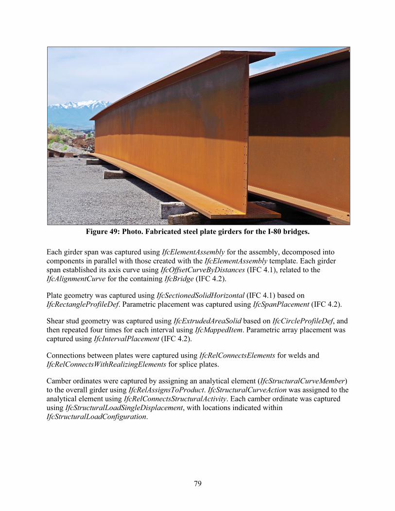
79
Figure 49: Photo. Fabricated steel plate girders for the I-80 bridges.
Each girder span was captured using IfcElementAssembly for the assembly, decomposed into components in parallel with those created with the IfcElementAssembly template. Each girder span established its axis curve using IfcOffsetCurveByDistances (IFC 4.1), related to the IfcAlignmentCurve for the containing IfcBridge (IFC 4.2).
Plate geometry was captured using IfcSectionedSolidHorizontal (IFC 4.1) based on IfcRectangleProfileDef. Parametric placement was captured using IfcSpanPlacement (IFC 4.2).
Shear stud geometry was captured using IfcExtrudedAreaSolid based on IfcCircleProfileDef, and then repeated four times for each interval using IfcMappedItem. Parametric array placement was captured using IfcIntervalPlacement (IFC 4.2).
Connections between plates were captured using IfcRelConnectsElements for welds and IfcRelConnectsWithRealizingElements for splice plates.
Camber ordinates were captured by assigning an analytical element (IfcStructuralCurveMember) to the overall girder using IfcRelAssignsToProduct. IfcStructuralCurveAction was assigned to the analytical element using IfcRelConnectsStructuralActivity. Each camber ordinate was captured using IfcStructuralLoadSingleDisplacement, with locations indicated within IfcStructuralLoadConfiguration.
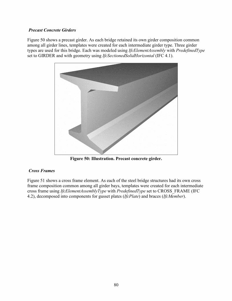
80
Precast Concrete Girders
Figure 50 shows a precast girder. As each bridge retained its own girder composition common among all girder lines, templates were created for each intermediate girder type. Three girder types are used for this bridge. Each was modeled using IfcElementAssembly with PredefinedType set to GIRDER and with geometry using IfcSectionedSolidHorizontal (IFC 4.1).
Figure 50: Illustration. Precast concrete girder.
Cross Frames
Figure 51 shows a cross frame element. As each of the steel bridge structures had its own cross frame composition common among all girder bays, templates were created for each intermediate cross frame using IfcElementAssemblyType with PredefinedType set to CROSS_FRAME (IFC 4.2), decomposed into components for gusset plates (IfcPlate) and braces (IfcMember).
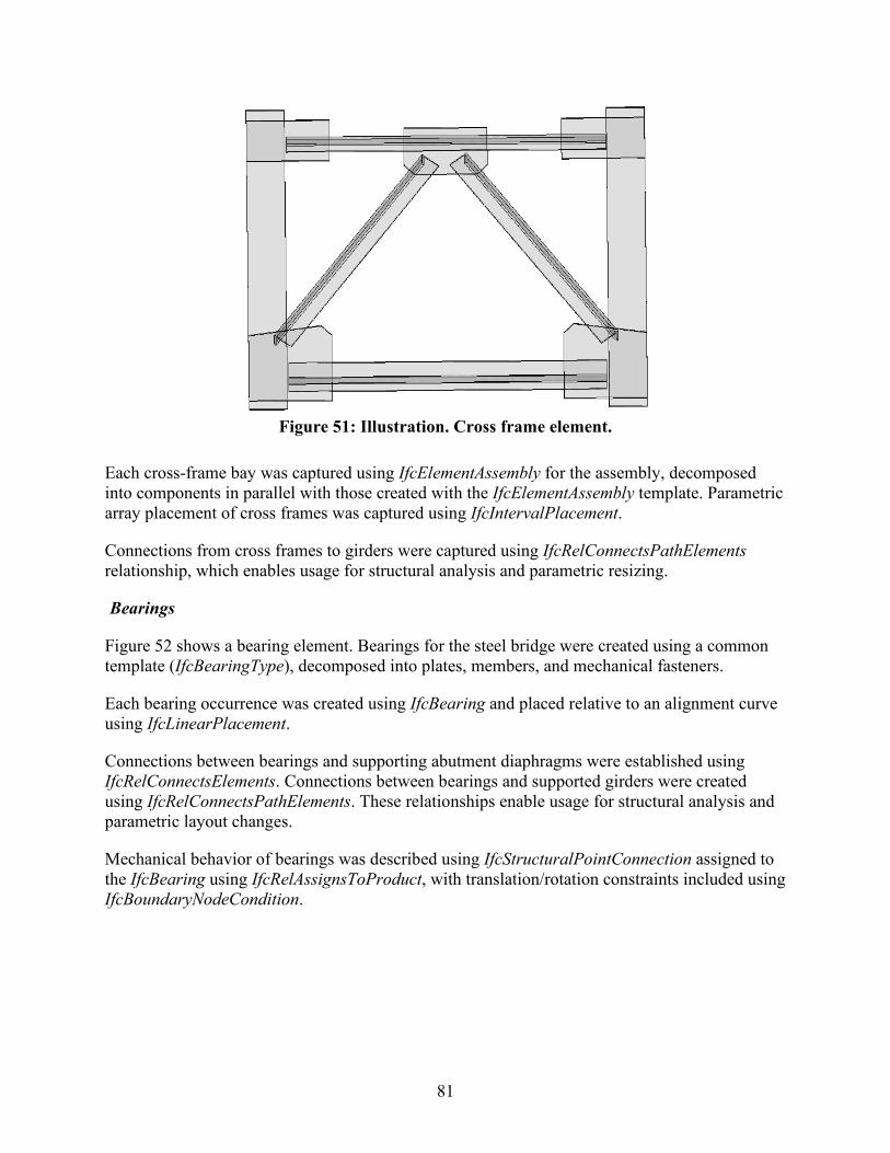
81
Figure 51: Illustration. Cross frame element.
Each cross-frame bay was captured using IfcElementAssembly for the assembly, decomposed into components in parallel with those created with the IfcElementAssembly template. Parametric array placement of cross frames was captured using IfcIntervalPlacement.
Connections from cross frames to girders were captured using IfcRelConnectsPathElements relationship, which enables usage for structural analysis and parametric resizing.
Bearings
Figure 52 shows a bearing element. Bearings for the steel bridge were created using a common template (IfcBearingType), decomposed into plates, members, and mechanical fasteners.
Each bearing occurrence was created using IfcBearing and placed relative to an alignment curve using IfcLinearPlacement.
Connections between bearings and supporting abutment diaphragms were established using IfcRelConnectsElements. Connections between bearings and supported girders were created using IfcRelConnectsPathElements. These relationships enable usage for structural analysis and parametric layout changes.
Mechanical behavior of bearings was described using IfcStructuralPointConnection assigned to the IfcBearing using IfcRelAssignsToProduct, with translation/rotation constraints included using IfcBoundaryNodeCondition.
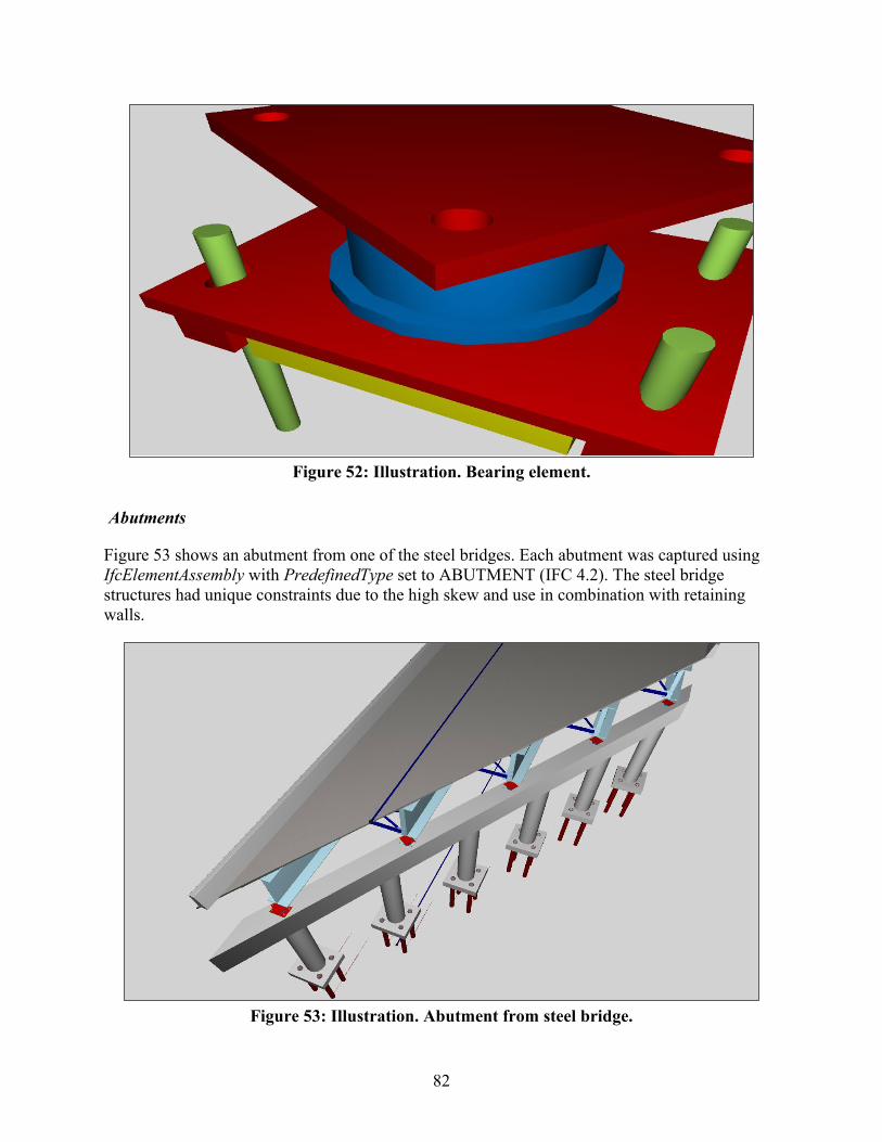
82
Figure 52: Illustration. Bearing element.
Abutments
Figure 53 shows an abutment from one of the steel bridges. Each abutment was captured using IfcElementAssembly with PredefinedType set to ABUTMENT (IFC 4.2). The steel bridge structures had unique constraints due to the high skew and use in combination with retaining walls.
Figure 53: Illustration. Abutment from steel bridge.
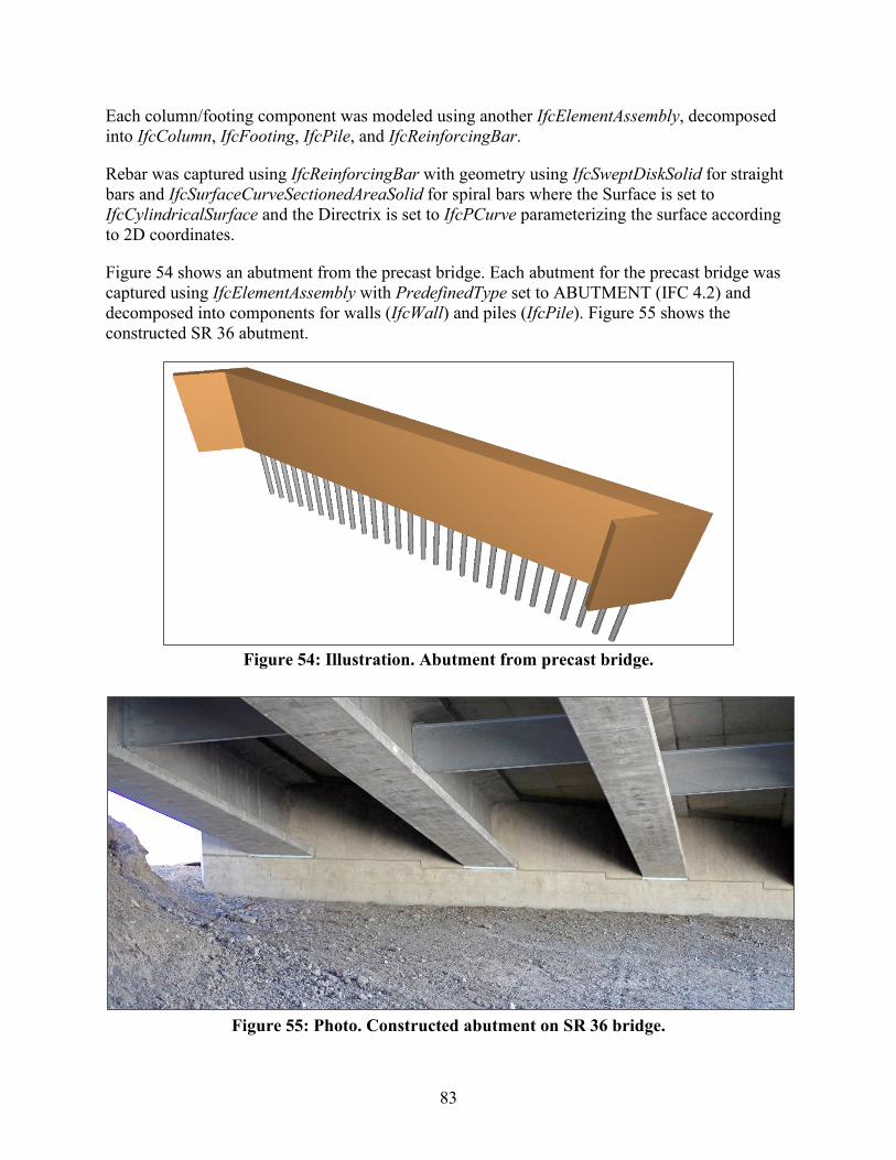
83
Each column/footing component was modeled using another IfcElementAssembly, decomposed into IfcColumn, IfcFooting, IfcPile, and IfcReinforcingBar.
Rebar was captured using IfcReinforcingBar with geometry using IfcSweptDiskSolid for straight bars and IfcSurfaceCurveSectionedAreaSolid for spiral bars where the Surface is set to IfcCylindricalSurface and the Directrix is set to IfcPCurve parameterizing the surface according to 2D coordinates.
Figure 54 shows an abutment from the precast bridge. Each abutment for the precast bridge was captured using IfcElementAssembly with PredefinedType set to ABUTMENT (IFC 4.2) and decomposed into components for walls (IfcWall) and piles (IfcPile). Figure 55 shows the constructed SR 36 abutment.
Figure 54: Illustration. Abutment from precast bridge.
Figure 55: Photo. Constructed abutment on SR 36 bridge.
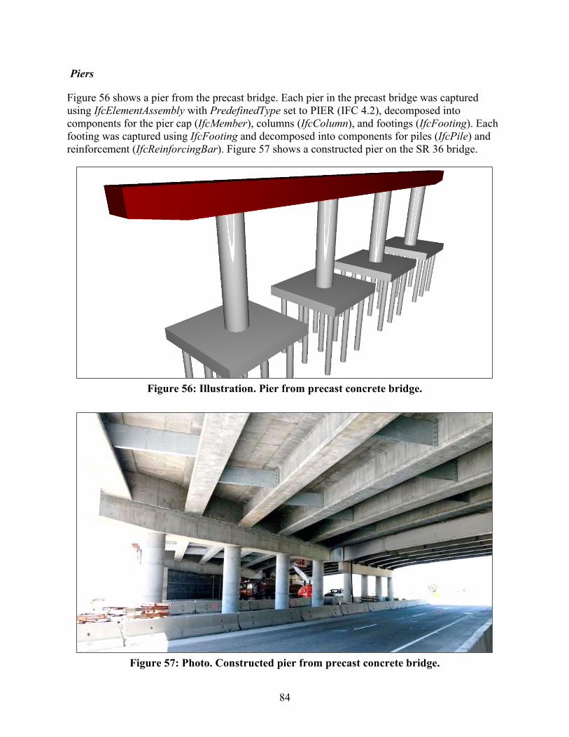
84
Piers
Figure 56 shows a pier from the precast bridge. Each pier in the precast bridge was captured using IfcElementAssembly with PredefinedType set to PIER (IFC 4.2), decomposed into components for the pier cap (IfcMember), columns (IfcColumn), and footings (IfcFooting). Each footing was captured using IfcFooting and decomposed into components for piles (IfcPile) and reinforcement (IfcReinforcingBar). Figure 57 shows a constructed pier on the SR 36 bridge.
Figure 56: Illustration. Pier from precast concrete bridge.
Figure 57: Photo. Constructed pier from precast concrete bridge.
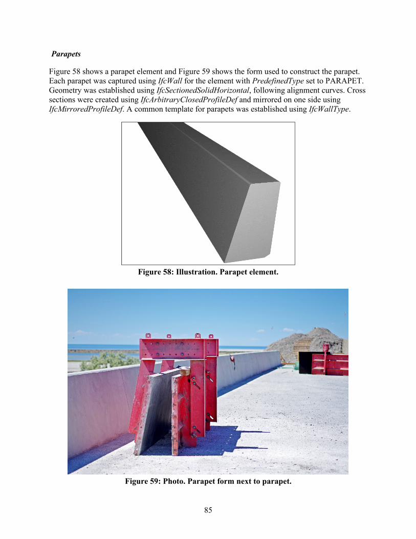
85
Parapets
Figure 58 shows a parapet element and Figure 59 shows the form used to construct the parapet. Each parapet was captured using IfcWall for the element with PredefinedType set to PARAPET. Geometry was established using IfcSectionedSolidHorizontal, following alignment curves. Cross sections were created using IfcArbitraryClosedProfileDef and mirrored on one side using IfcMirroredProfileDef. A common template for parapets was established using IfcWallType.
Figure 58: Illustration. Parapet element.
Figure 59: Photo. Parapet form next to parapet.
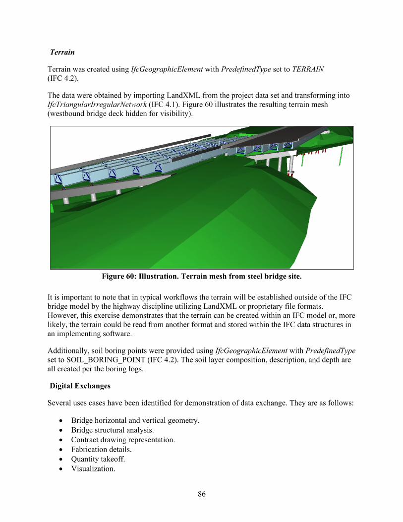
86
Terrain
Terrain was created using IfcGeographicElement with PredefinedType set to TERRAIN (IFC 4.2).
The data were obtained by importing LandXML from the project data set and transforming into IfcTriangularIrregularNetwork (IFC 4.1). Figure 60 illustrates the resulting terrain mesh (westbound bridge deck hidden for visibility).
Figure 60: Illustration. Terrain mesh from steel bridge site.
It is important to note that in typical workflows the terrain will be established outside of the IFC bridge model by the highway discipline utilizing LandXML or proprietary file formats. However, this exercise demonstrates that the terrain can be created within an IFC model or, more likely, the terrain could be read from another format and stored within the IFC data structures in an implementing software.
Additionally, soil boring points were provided using IfcGeographicElement with PredefinedType set to SOIL_BORING_POINT (IFC 4.2). The soil layer composition, description, and depth are all created per the boring logs.
Digital Exchanges
Several uses cases have been identified for demonstration of data exchange. They are as follows:
• Bridge horizontal and vertical geometry. • Bridge structural analysis. • Contract drawing representation. • Fabrication details. • Quantity takeoff. • Visualization.

87
• Component spatial clash detection. • Shop drawing development and as-built drawings.
The following investigates the exchanges in the selected use cases through the IFC data format. To validate the exchanges, the general process is to export the data from one software and import that data in a separate software application. This is done as a test to show that the information is not just captured in a particular software language but is captured in the neutral IFC format that can be replicated in another software that implements IFC. Challenges to this approach mostly relate to the lack of commercially available software implementing IFC 4.0 and later releases that provide certain components in the selected exchanges. Where this occurs, the IFC models/exchanges are “downgraded” to IFC 2.3 as described in the commentary of the model development section of this report.
This procedure allows for seeing the current applicability and usability of the IFC data in software today and shows the potential for how the data could be used in the future. With additional MVDs developed for these exchanges and software developers implementing these data structures, data can transfer much more seamlessly and without the additional need for manual manipulation of the data. This highlights the importance of additional standardization work.
Bridge Horizontal and Vertical Geometry
The geometry exchange captures the physical dimensions and placement of bridges established according to horizontal and vertical alignment curves. As data structures for this capability were introduced in IFC 4.1, data are provided in this form for each bridge.
• Exporting Software: (Custom Tools). • Importing Software: TUM OpenInfra Platform.
The generated files were downgraded to IFC 4.1 and imported into TUM Open Infra Platform. Figure 61 shows a small section of the vertical profile.
Figure 61: Graph. Representation of vertical profile as viewed in
TUM OpenInfra Platform.
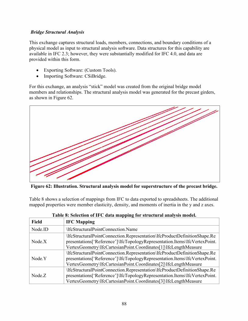
88
Bridge Structural Analysis
This exchange captures structural loads, members, connections, and boundary conditions of a physical model as input to structural analysis software. Data structures for this capability are available in IFC 2.3; however, they were substantially modified for IFC 4.0, and data are provided within this form.
• Exporting Software: (Custom Tools). • Importing Software: CSiBridge.
For this exchange, an analysis “stick” model was created from the original bridge model members and relationships. The structural analysis model was generated for the precast girders, as shown in Figure 62.
Figure 62: Illustration. Structural analysis model for superstructure of the precast bridge.
Table 8 shows a selection of mappings from IFC to data exported to spreadsheets. The additional mapped properties were member elasticity, density, and moments of inertia in the y and z axes.
Table 8: Selection of IFC data mapping for structural analysis model. Field IFC Mapping Node.ID \IfcStructuralPointConnection.Name
Node.X \IfcStructuralPointConnection.Representation\IfcProductDefinitionShape.Representations[‘Reference’]\IfcTopologyRepresentation.Items\IfcVertexPoint.VertexGeometry\IfcCartesianPoint.Coordinates[1]\IfcLengthMeasure
Node.Y \IfcStructuralPointConnection.Representation\IfcProductDefinitionShape.Representations[‘Reference’]\IfcTopologyRepresentation.Items\IfcVertexPoint.VertexGeometry\IfcCartesianPoint.Coordinates[2]\IfcLengthMeasure
Node.Z \IfcStructuralPointConnection.Representation\IfcProductDefinitionShape.Representations[‘Reference’]\IfcTopologyRepresentation.Items\IfcVertexPoint.VertexGeometry\IfcCartesianPoint.Coordinates[3]\IfcLengthMeasure
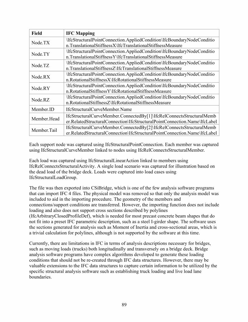
89
Field IFC Mapping
Node.TX \IfcStructuralPointConnection.AppliedCondition\IfcBoundaryNodeCondition.TranslationalStiffnessX\IfcTranslationalStiffnessMeasure
Node.TY \IfcStructuralPointConnection.AppliedCondition\IfcBoundaryNodeCondition.TranslationalStiffnessY\IfcTranslationalStiffnessMeasure
Node.TZ \IfcStructuralPointConnection.AppliedCondition\IfcBoundaryNodeCondition.TranslationalStiffnessZ\IfcTranslationalStiffnessMeasure
Node.RX \IfcStructuralPointConnection.AppliedCondition\IfcBoundaryNodeCondition.RotationalStiffnessX\IfcRotationalStiffnessMeasure
Node.RY \IfcStructuralPointConnection.AppliedCondition\IfcBoundaryNodeCondition.RotationalStiffnessY\IfcRotationalStiffnessMeasure
Node.RZ \IfcStructuralPointConnection.AppliedCondition\IfcBoundaryNodeCondition.RotationalStiffnessZ\IfcRotationalStiffnessMeasure
Member.ID IfcStructuralCurveMember.Name
Member.Head IfcStructuralCurveMember.ConnectedBy[1]\IfcRelConnectsStructuralMember.RelatedStructuralConnection\IfcStructuralPointConnection.Name\IfcLabel
Member.Tail IfcStructuralCurveMember.ConnectedBy[2]\IfcRelConnectsStructuralMember.RelatedStructuralConnection\IfcStructuralPointConnection.Name\IfcLabel
Each support node was captured using IfcStructuralPointConnection. Each member was captured using IfcStructuralCurveMember linked to nodes using IfcRelConnectsStructuralMember.
Each load was captured using IfcStructuralLinearAction linked to members using IfcRelConnectsStructuralActivity. A single load scenario was captured for illustration based on the dead load of the bridge deck. Loads were captured into load cases using IfcStructuralLoadGroup.
The file was then exported into CSiBridge, which is one of the few analysis software programs that can import IFC 4 files. The physical model was removed so that only the analysis model was included to aid in the importing procedure. The geometry of the members and connections/support conditions are transferred. However, the importing function does not include loading and also does not support cross sections described by polylines (IfcArbitraryClosedProfileDef), which is needed for most precast concrete beam shapes that do not fit into a preset IFC parametric description, such as a steel I-girder shape. The software uses the sections generated for analysis such as Moment of Inertia and cross-sectional areas, which is a trivial calculation for polylines, although is not supported by the software at this time.
Currently, there are limitations in IFC in terms of analysis descriptions necessary for bridges, such as moving loads (trucks) both longitudinally and transversely on a bridge deck. Bridge analysis software programs have complex algorithms developed to generate these loading conditions that should not be re-created through IFC data structures. However, there may be valuable extensions to the IFC data structures to capture certain information to be utilized by the specific structural analysis software such as establishing truck loading and live load lane boundaries.

90
Contract Drawing Representation
This exchange captures details as shown on design plans. Some bridge-specific parameters are only possible in the unreleased IFC 4.2, and others possible with IFC 4.1. As most widely released BIM software capable of generating drawings still only supports IFC 2.3, the exchange is based on downgrading to IFC 2.3. Thus, bridge alignment dimensions are lost; however, dimensions for cartesian elements are retained.
• Exporting Software: Constructivity. • Importing Software: Bentley MicroStation, Microsoft Excel.
As IFC does not support dimensioning of physical objects, specific dimension lines as found on plans are not included in the exchange and thus cannot be replicated. However, software on the receiving end may automatically generate dimension lines when producing plan sets.
Below are several elements critical in contract drawing representation. These are used to demonstrate the capability of current IFC data structures to capture the desired information to develop a set of contract drawings.
Dimensioning and Annotation
As previously demonstrated, all of the geometric information for the structural elements of the bridge are captured within the IFC model. Therefore, these elements can be imported into software, views and section cuts, and dimensions and annotations created to represent the traditional 2D contract drawing sets. This is illustrated with a steel cross frame in Figure 63 in which the IFC model was imported into MicroStation to re-create the cross frame detail from the steel bridge contract plans.
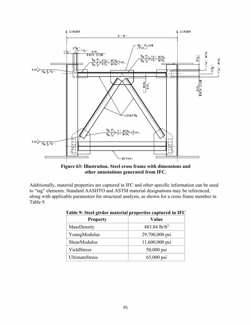
91
Figure 63: Illustration. Steel cross frame with dimensions and
other annotations generated from IFC.
Additionally, material properties are captured in IFC and other specific information can be used to “tag” elements. Standard AASHTO and ASTM material designations may be referenced, along with applicable parameters for structural analysis, as shown for a cross frame member in Table 9.
Table 9: Steel girder material properties captured in IFC Property Value
MassDensity 483.84 lb/ft3 YoungModulus 29,700,000 psi ShearModulus 11,600,000 psi YieldStress 50,000 psi UltimateStress 65,000 psi
92
Reinforcement Representation and Scheduling
Concrete reinforcement is a common element between vertical and horizontal industries and is well-established and mature within IFC data structures. The reinforcement shapes, marks, numbers, and materials are all captured within current IFC data structures. A parapet with the reinforcement is shown in Figure 64, which illustrates the bar and conduit information.
Figure 64: Illustration. Parapet reinforcement and utility ducts.
In current versions of IFC, each reinforcement bar is captured as a separate case. Therefore, groups or sets of reinforcement are only identified by mark and placement. In other words, the relationship between bar spacing or total number of bars in a set distance cannot be explicitly captured in IFC currently. However, new data structures to be introduced in the near future can handle reinforcement bar sets and elements such as spacing. See additional discussion in the Fabrication Details, Shop Drawings, and Processes section of this chapter.
For schedules shown in plan sets, such as reinforcement schedules, IFC provides data structures for schedules, leveraging IfcTable, IfcTableColumn, IfcTableRow, and IfcReference. These data structures may be encapsulated in IFC files for preserving mappings and automatically synchronizing data between spreadsheets, databases, or other tabular data formats.
For the demonstration project, the reinforcement schedule was represented in the IFC file and the data were exported to a spreadsheet. Table 10 illustrates the column mappings for extracting the reinforcement schedule from the IFC file.
Table 10: IFC data mapping for reinforcement schedules. Field IFC Mapping
Bar.Mark IfcReinforcingBarType.Name Bar.Diameter IfcReinforcingBarType.NominalDiameter Bar.Length IfcReinforcingBarType.BarLength Bar.Surface IfcReinforcingBarType.BarSurface
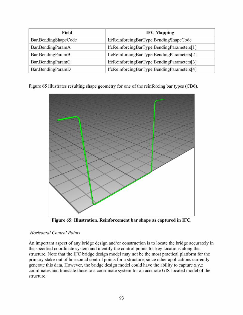
93
Field IFC Mapping Bar.BendingShapeCode IfcReinforcingBarType.BendingShapeCode Bar.BendingParamA IfcReinforcingBarType.BendingParameters[1] Bar.BendingParamB IfcReinforcingBarType.BendingParameters[2] Bar.BendingParamC IfcReinforcingBarType.BendingParameters[3] Bar.BendingParamD IfcReinforcingBarType.BendingParameters[4]
Figure 65 illustrates resulting shape geometry for one of the reinforcing bar types (CB6).
Figure 65: Illustration. Reinforcement bar shape as captured in IFC.
Horizontal Control Points
An important aspect of any bridge design and/or construction is to locate the bridge accurately in the specified coordinate system and identify the control points for key locations along the structure. Note that the IFC bridge design model may not be the most practical platform for the primary stake-out of horizontal control points for a structure, since other applications currently generate this data. However, the bridge design model could have the ability to capture x,y,z coordinates and translate those to a coordinate system for an accurate GIS-located model of the structure.
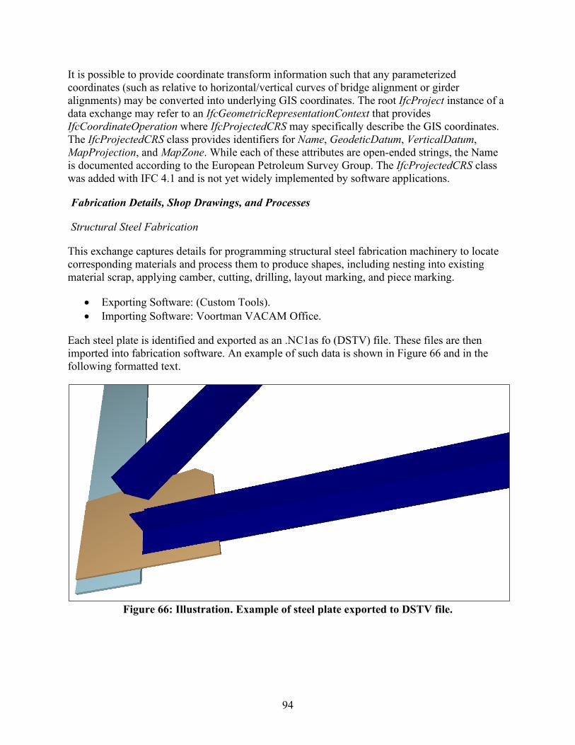
94
It is possible to provide coordinate transform information such that any parameterized coordinates (such as relative to horizontal/vertical curves of bridge alignment or girder alignments) may be converted into underlying GIS coordinates. The root IfcProject instance of a data exchange may refer to an IfcGeometricRepresentationContext that provides IfcCoordinateOperation where IfcProjectedCRS may specifically describe the GIS coordinates. The IfcProjectedCRS class provides identifiers for Name, GeodeticDatum, VerticalDatum, MapProjection, and MapZone. While each of these attributes are open-ended strings, the Name is documented according to the European Petroleum Survey Group. The IfcProjectedCRS class was added with IFC 4.1 and is not yet widely implemented by software applications.
Fabrication Details, Shop Drawings, and Processes
Structural Steel Fabrication
This exchange captures details for programming structural steel fabrication machinery to locate corresponding materials and process them to produce shapes, including nesting into existing material scrap, applying camber, cutting, drilling, layout marking, and piece marking.
• Exporting Software: (Custom Tools). • Importing Software: Voortman VACAM Office.
Each steel plate is identified and exported as an .NC1as fo (DSTV) file. These files are then imported into fabrication software. An example of such data is shown in Figure 66 and in the following formatted text.
Figure 66: Illustration. Example of steel plate exported to DSTV file.
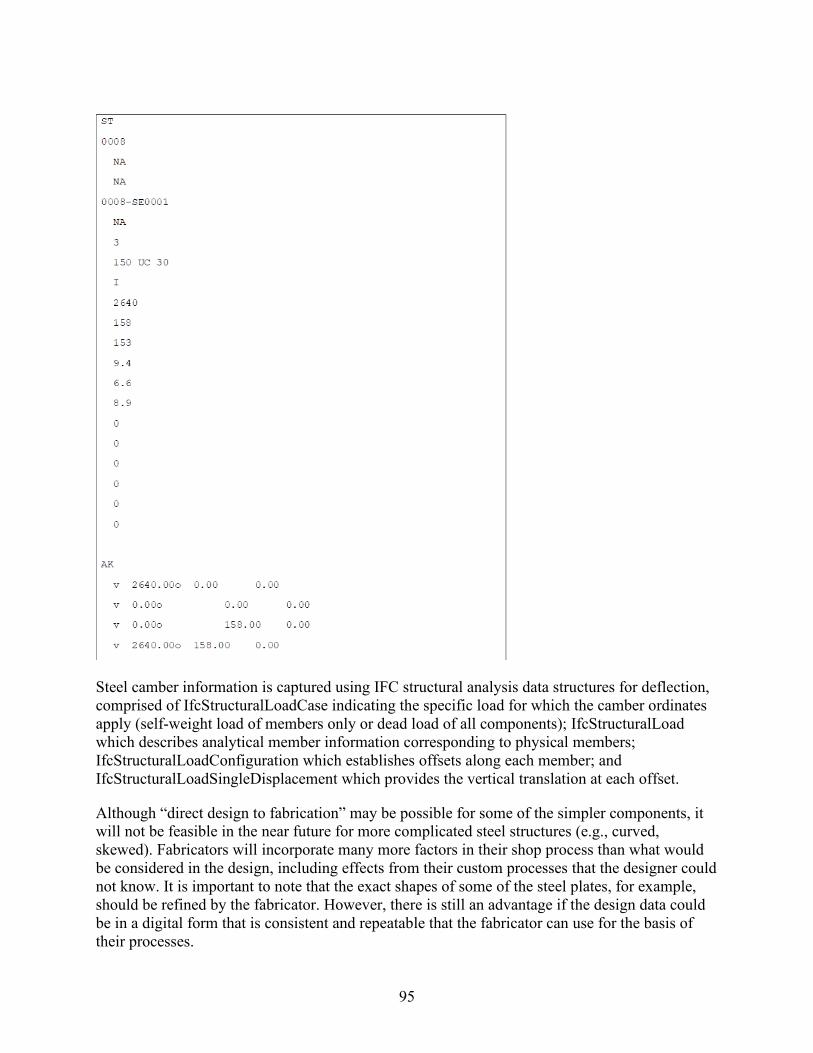
95
Steel camber information is captured using IFC structural analysis data structures for deflection, comprised of IfcStructuralLoadCase indicating the specific load for which the camber ordinates apply (self-weight load of members only or dead load of all components); IfcStructuralLoad which describes analytical member information corresponding to physical members; IfcStructuralLoadConfiguration which establishes offsets along each member; and IfcStructuralLoadSingleDisplacement which provides the vertical translation at each offset.
Although “direct design to fabrication” may be possible for some of the simpler components, it will not be feasible in the near future for more complicated steel structures (e.g., curved, skewed). Fabricators will incorporate many more factors in their shop process than what would be considered in the design, including effects from their custom processes that the designer could not know. It is important to note that the exact shapes of some of the steel plates, for example, should be refined by the fabricator. However, there is still an advantage if the design data could be in a digital form that is consistent and repeatable that the fabricator can use for the basis of their processes.

96
The demonstration also shows that the models could be used as shop “drawings” or more accurately shop models as all the general information for fabrication is captured and additional information for specific fabrication processes added as attributes. However, the biggest challenge in the conversion to a model-based shop drawing process is the inexperience of fabricators, specifically shop floor personnel, in using and understanding this information in a model form.
Additional Exchanges with Blackrock Fabricators—Concrete Reinforcement
In addition to the typical exchange investigation completed in the other sections, supplementary exchanges directly with the fabricators on the Blackrock project were explored. This area is of special interest in BIM and further development in the design to fabrication exchanges is identified as a next step in this and related research efforts. All three major fabricators in the project (prestressed concrete girders, structural steel girders, and concrete reinforcement) were contacted and information about how each fabricator used the model for their processes was collected.
After review, it was determined that the concrete reinforcement fabricator, Harris Rebar, offered the greatest potential to provide a demonstration on a design to fabrication IFC exchange. Harris Rebar had used IFC files generated from the UDOT model in the project delivery and are experienced in using IFC exchanges in work for other industries. Therefore, exchanges were completed directly with the fabricator to determine the extent to which they could use the IFC data generated from the demonstration model.
This exchange captures details used in generating bending schedules and placement drawings, and the details needed for programming bar bending machinery.
• Exporting Software: (Custom Tools). • Importing Software: Tekla® Structures.
IFC 4.0 is used for the exporting files to employ new data structures introduced in this version which are used to create grouped reinforcement sets as assemblies with individual bars as component objects. Previous versions of IFC can only capture the individual bars, not view them as repeatable “sets” of bars. The precast deck panels are one example included in the models of leveraging repetition patterns in reinforcement (IfcPlateType “Deck Panel WB”), where bars are repeated per panel, then panels are repeated per girder bay, as shown in Figure 67 and Figure 68.
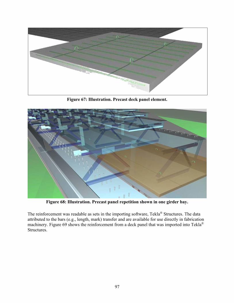
97
Figure 67: Illustration. Precast deck panel element.
Figure 68: Illustration. Precast panel repetition shown in one girder bay.
The reinforcement was readable as sets in the importing software, Tekla® Structures. The data attributed to the bars (e.g., length, mark) transfer and are available for use directly in fabrication machinery. Figure 69 shows the reinforcement from a deck panel that was imported into Tekla® Structures.
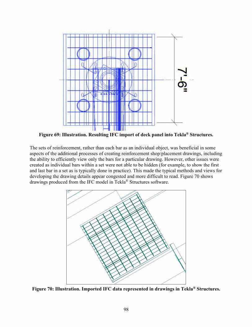
98
Figure 69: Illustration. Resulting IFC import of deck panel into Tekla® Structures.
The sets of reinforcement, rather than each bar as an individual object, was beneficial in some aspects of the additional processes of creating reinforcement shop/placement drawings, including the ability to efficiently view only the bars for a particular drawing. However, other issues were created as individual bars within a set were not able to be hidden (for example, to show the first and last bar in a set as is typically done in practice). This made the typical methods and views for developing the drawing details appear congested and more difficult to read. Figure 70 shows drawings produced from the IFC model in Tekla® Structures software.
Figure 70: Illustration. Imported IFC data represented in drawings in Tekla® Structures.
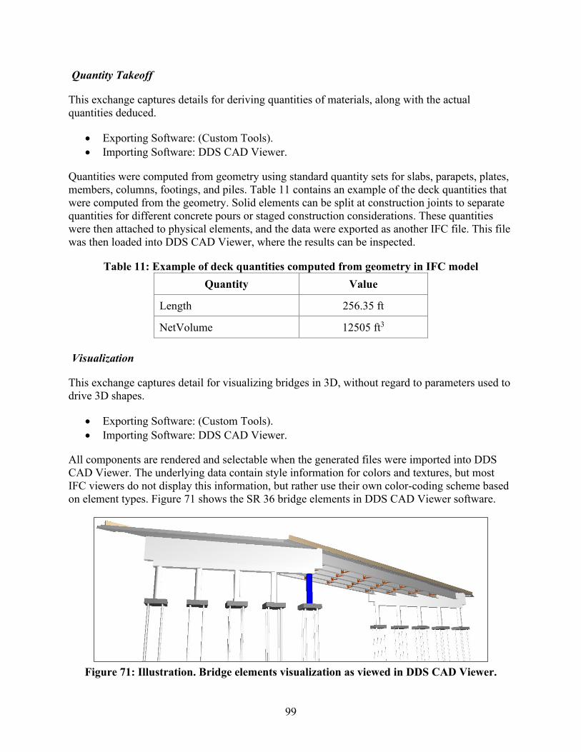
99
Quantity Takeoff
This exchange captures details for deriving quantities of materials, along with the actual quantities deduced.
• Exporting Software: (Custom Tools). • Importing Software: DDS CAD Viewer.
Quantities were computed from geometry using standard quantity sets for slabs, parapets, plates, members, columns, footings, and piles. Table 11 contains an example of the deck quantities that were computed from the geometry. Solid elements can be split at construction joints to separate quantities for different concrete pours or staged construction considerations. These quantities were then attached to physical elements, and the data were exported as another IFC file. This file was then loaded into DDS CAD Viewer, where the results can be inspected.
Table 11: Example of deck quantities computed from geometry in IFC model Quantity Value
Length 256.35 ft
NetVolume 12505 ft3
Visualization
This exchange captures detail for visualizing bridges in 3D, without regard to parameters used to drive 3D shapes.
• Exporting Software: (Custom Tools). • Importing Software: DDS CAD Viewer.
All components are rendered and selectable when the generated files were imported into DDS CAD Viewer. The underlying data contain style information for colors and textures, but most IFC viewers do not display this information, but rather use their own color-coding scheme based on element types. Figure 71 shows the SR 36 bridge elements in DDS CAD Viewer software.
Figure 71: Illustration. Bridge elements visualization as viewed in DDS CAD Viewer.
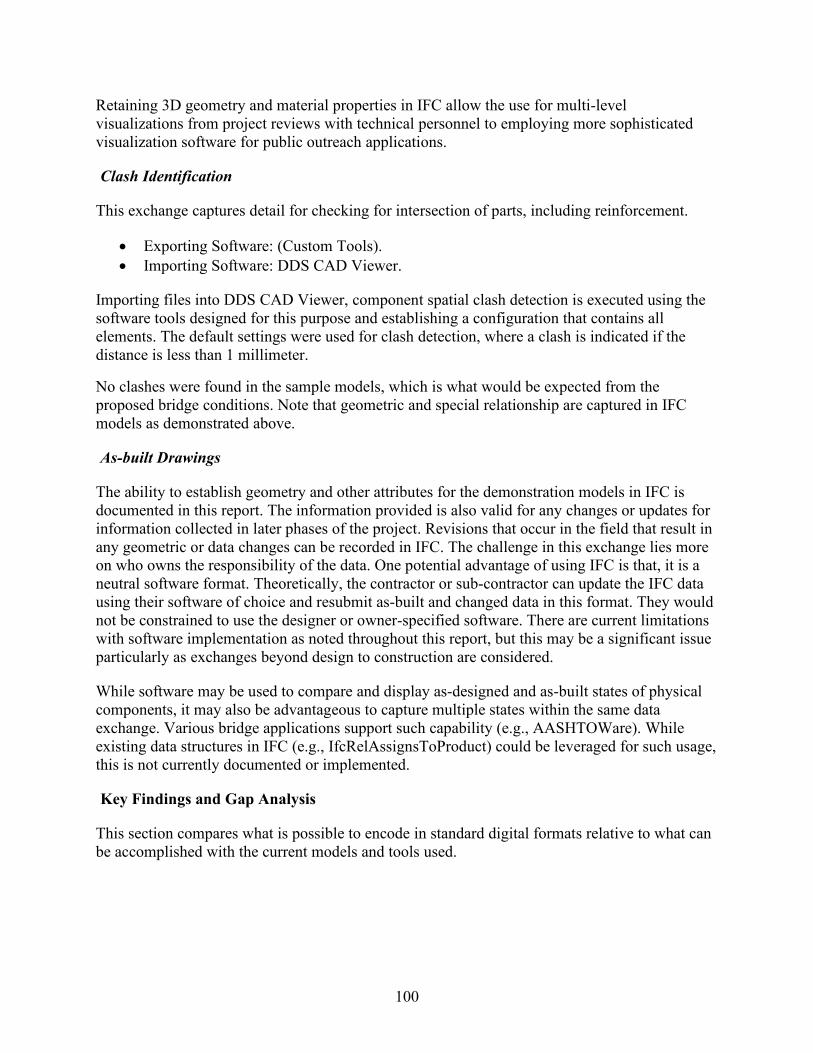
100
Retaining 3D geometry and material properties in IFC allow the use for multi-level visualizations from project reviews with technical personnel to employing more sophisticated visualization software for public outreach applications.
Clash Identification
This exchange captures detail for checking for intersection of parts, including reinforcement.
• Exporting Software: (Custom Tools). • Importing Software: DDS CAD Viewer.
Importing files into DDS CAD Viewer, component spatial clash detection is executed using the software tools designed for this purpose and establishing a configuration that contains all elements. The default settings were used for clash detection, where a clash is indicated if the distance is less than 1 millimeter.
No clashes were found in the sample models, which is what would be expected from the proposed bridge conditions. Note that geometric and special relationship are captured in IFC models as demonstrated above.
As-built Drawings
The ability to establish geometry and other attributes for the demonstration models in IFC is documented in this report. The information provided is also valid for any changes or updates for information collected in later phases of the project. Revisions that occur in the field that result in any geometric or data changes can be recorded in IFC. The challenge in this exchange lies more on who owns the responsibility of the data. One potential advantage of using IFC is that, it is a neutral software format. Theoretically, the contractor or sub-contractor can update the IFC data using their software of choice and resubmit as-built and changed data in this format. They would not be constrained to use the designer or owner-specified software. There are current limitations with software implementation as noted throughout this report, but this may be a significant issue particularly as exchanges beyond design to construction are considered.
While software may be used to compare and display as-designed and as-built states of physical components, it may also be advantageous to capture multiple states within the same data exchange. Various bridge applications support such capability (e.g., AASHTOWare). While existing data structures in IFC (e.g., IfcRelAssignsToProduct) could be leveraged for such usage, this is not currently documented or implemented.
Key Findings and Gap Analysis
This section compares what is possible to encode in standard digital formats relative to what can be accomplished with the current models and tools used.

101
Use Cases
For such data to be sufficient for downstream usage, various aspects should be incorporated as follows, all of which is possible with data structures used in any supported version of IFC (2.3, 4.0, 4.1), except where a specific version is indicated:
• As necessary for fabrication, objects should be separated according to discrete parts (e.g., construction plans show flange plates with varying dimensions along span, having adjoining splice plates); plate geometry should be described according to constant thickness and bounding dimensions with holes included, rather than BREP; cross-frame members should be described according to shape parameters in order to locate/identify standard American Institute of Steel Construction (AISC) shapes; components should capture welds, splice plates, and shear studs.
• As necessary for structural analysis, object geometry should reflect extruded cross sections as applicable; connections between objects should be specified along with mechanical behavior; materials are described with mechanical properties (e.g., elastic modulus, shear modulus, density); load cases should be specified.
• As necessary for construction, object geometry should reflect shapes as indicated on plans (e.g., pier columns and piles described as cylinders rather than BREP); object placement and spans should be determined relative to alignments [IFC 4.1], rather than global cartesian coordinates; object materials should be specified (e.g., steel or concrete along with strength specifications).
• As necessary for human usability (and to reflect organization as shown on construction plans), objects should be instantiated and re-used (e.g., standard cross frame created once and repeated, rather than duplicated); objects should be typed (e.g., designate a pile); objects should be named (e.g., “G2” for second girder as shown on plans); and objects should be grouped (e.g., abutment object containing components within).
• As necessary for quantity takeoff, objects should be typed, use parameterized geometry reflecting exact shape, and provide material information.
Automated Refinement
Given the data as exported with current tools (using IFC and COLLADA™ formats), automated steps were undertaken to partially achieve the desired results above based on algorithms making various assumptions.
The refinement process involved the following steps:
1. Splitting each mesh into elements for each connected subset of faces. 2. Normalizing the origin for each derived mesh. 3. Generating shared descriptions for equivalent meshes and referencing them. 4. Converting arbitrary meshes into extruded solids of arbitrary cross sections. 5. Converting arbitrary cross sections into parameterized cross sections (e.g., circle,
I-Shape). 6. Generating connection relationships based on interference detection. 7. Classifying objects. 8. Aggregating objects.

102
For the COLLADA™ export, Steps 1 through 8 were necessary. Single meshes were generated on a per-layer basis instead of for each common shape, and text annotations were exported as meshes capturing every font character, which contributed to a substantial portion of file sizes.
For the IFC export, Steps 3 through 8 were necessary. Single meshes were generated on a functional component basis instead of for each discrete element.
Schema Developments Needed
In evaluating the given use cases, several categories emerged of aspects that cannot be sufficiently modeled using existing IFC data structures.
For layout of bridges with skew, skew lines are indicated where girder and deck dimensions are determined relative to such skew lines, to match typical usage; providing offsets for every member is redundant and loses such data dependencies.
For repetitive components such as reinforcement bars, shear studs, precast panels, cross-frames, and diaphragms, these are typically shown once in drawings and then repeated according to a pattern. In cases of cross-frames, the dimensions and positioning of components within individual instances may vary according to relative elevations of adjoining girders.
For components where the contractor has flexibility, there should be a formal way to convey this in digital exchanges—for example, provisions are made for hooks in precast elements, but the specific layout and positioning is up to the contractor/fabricator; similarly, reinforcement may be described according to maximum spacing without exact layout.
Various common shapes used for bridges do not have direct ways of modeling without falling back on tessellation, boundary representation, and/or arbitrary curves, which entails receiving software transforming such information to make the dimensions understandable for contractors. Examples of such shapes are bent plates, bridge decks with skew that may be squared off at edges, and cross sections of precast girders having chamfers.
For fabricated shapes, there should be a way to distinguish components from their theoretical shapes as typically exchanged in BIM authoring tools, from representations provided for fabrication that indicate camber for different loading scenarios. While data structures exist to capture such information, nothing is currently documented in the IFC schema to make such usage obvious.
103
CHAPTER 7 KEY FINDINGS AND SUGGESTIONS
This research supplies resources for State transportation agencies. First, sample technical specifications assist in identifying BIM needs for projects. Second, it tests an implementation of the IFC Bridge Design-to-Construction Information Exchange (U.S.) MVD. (54) The testing results provided feedback to national(15) and international(14) efforts. The obstacles and opportunities for immediate implementation with current state of practice are documented. Third, an AASHTOWare BrD to IFC Exchange Utility is available to convert current BrD files into IFC based on the previously developed private, voluntary specifications.
Using Digital Delivery Today
UDOT has demonstrated that it is possible to use digital delivery today to construct and fabricate complex workhorse bridges using an approach with proprietary software and user-defined digital annotations and attachments for work-arounds as needed. However, UDOT also demonstrated several challenges to doing so and the roles of partnering and alternate procurement to mitigate the risks.
The project used a procurement method that enabled UDOT to select a qualified consultant and contractor. Nevertheless, one of the main challenges was a lack of experience with 3D models both in the design phase and in the field. An incremental approach to BIM-based delivery may give agencies and their project development partners more time to raise the skill level organically. Faster implementation would involve substantial training investments across the industry.
Agencies wishing to implement BIM-based delivery for bridges may be interested to note the following:
• Until vendors implement data standards into commercial software, the potential for dataloss or data corruption remains a risk that should be carefully managed.
• In-person model review meetings were an effective way to create uniform understandingand to transfer 3D modeling skills, but the strategy may not scale to larger projects.
• Craft workers relied on surveyors to perform or check layout because they had lowconfidence with extracting layout information from the model.
State agencies wishing to move beyond piloting digital delivery may benefit from spending time developing and documenting workflows and non-binding reference standards, manuals, and guides. These would form the basis of training materials and the foundation of technical processes, procedures, and deliverables related to the digital media. Standards for presenting information—regardless of the file format—are important to providing predictable, repeatable experiences with digital contract documents and reduce the learning curve.
104
Using IFC with State Bridge Inventories
The AASHTOWare bridge products share a well-designed data model that can be mapped to IFC for most workhorse bridges. For more general use, The AASHTOWare BRD to IFC Exchange Utility could be incorporated into the AASHTOWare software allowing IFC as an additional export option. At the time of publication, AASHTOWare is currently engaging in a modernization project but there is interest in adding this functionality in the future.
The AASHTOWare bridge products store the bridge geometry for the purposes of performing structural analysis, such as for load rating, routing, and design. Generally, States store the geometry at only the level of detail used for these functions. Information necessary for construction, such as vertical curvature, terrain, electrical conduit, drainage, and architectural features, are not captured within the AASHTOWare bridge database.
Conceptually, the IFC to AASHTOWare data model mapping would enable States to import new or revised bridges into their inventory using IFC. Importing newly designed bridges into AASHTOWare bridge management software would involve simplifying more complex geometry. This is a task that includes engineering judgment, potentially making use of additional parameters to control such conversions. Expanding the IFC standard to cover the design to structural analysis exchange would establish the rules and procedures to automate this import.
Using IFC for Bridge Construction and Fabrication
In general, the bridges tested in this research were well described by the IFC 4.1 and early (although not yet adopted) IFC 4.2 data structures. However, some limitations to the IFC data structures were identified during the course of this research. The following extensions are suggested to fully describe bridge geometry for construction and fabrication:
• Position by skew, where bridge decks, girders, reinforcement, and other components are placed and shaped relative to skew lines.
• Repetitive components such as reinforcement, shear studs, and precast panels—not just for efficiency in interpretation, but to reflect the intent as conveyed on construction plans.
• Repetitive assemblies where placement and geometry vary according to placement conditions, such as cross frames.
• Parametric descriptions of common cross sections, such as common precast girders and barriers/railings.
This research found that it would be beneficial to refine the previously developed Industry Foundation Class (IFC) Bridge Design to Construction Information Exchange (U.S.) MVD in two areas. First, to provide direction on how to represent constrained and provisional data. Second, to provide information for capturing multiple representations of the same component for different usages.
105
This research found that it may be useful to develop additional data to describe bridge information exchanges. Specifically, these exchanges may include:
• Design to fabrication supporting structural steel, prestressed girders, and concrete reinforcement.
• Design to structural analysis to include information sufficient for finite-element analysis, as well as details necessary for AASHTO, the American Concrete Institute, and AISC design.
The active development of the IFC standard for bridges and its consequent lack of adoption of recent versions into commercial software products may limit bridge owners’ use of IFC for bridges.
BIM Object template
One particular area suggested for further development is identifying information that is used to establish a formal digital description of an object. The object data to be transmitted and received for the intended purpose should be described precisely. Such description may then be used to create new objects that are used repeatedly. Bridge stakeholders familiar with the engineering workflow steps and data exchanges could make suggestions to refine and extend the data to be captured. A BIM object “template” can be created to describe this data.
Template Introduction
A BIM object template is a tool to provide a structured approach to providing input to describe and expand digital descriptions and associated software standards. Stakeholders could use the template to describe data for specific types of bridge or structural elements. The template captures information that is necessary for a particular use (such as to design, construct, or inspect the object). The template enables stakeholders to communicate their data needs in a form that software developers can use.
The template describes data using parameters that are consistent with existing forms, such as how the information is detailed in construction drawings. This approach is purposely independent of underlying BIM data schemas (e.g., IFC) to avoid the constraints imposed by current limits of existing data models. This also recognizes that these data models may not provide the level of specificity that is critical for specific bridge elements and may not necessarily be amenable to capture the necessary detail. Current developments within buildingSmart suggest that future IFC versions (e.g., 5.0) may undergo significant changes; references to existing IFC data structures may become obsolete. For all of these reasons, the preferred approach to detailing data structures is to organize input according to how the intended recipient would describe the data in a sustainable manner that is understandable to engineers.
An outside entity has the capability to map the fields described in the template to data schemas (e.g., IFC, LandXML). These mappings may then be used as a basis for modifying those schemas and/or documenting usage and mappings of existing schemas. Finland’s OpenInfra schema has established custom attributes layered within LandXML. BuildingSmart has referred to such mappings for IFC as MVDs.

106
Depending on how far an underlying data schema addresses specific data structures, some data may be formally described within such schemas, while others may be represented as templates generated at a higher level without any explicit underlying data structures. For example, IFC and LandXML support custom “properties” where arbitrary name/value pairs can be used.
Template Structure
The purpose of this template is to describe data for specific types of bridge and structure objects. The template specifically focuses on physical objects to be designed, fabricated, or constructed and captures information that is used by the sender/receiver of the information. This is to be a method for stakeholders to communicate this data in a form that software developers can understand and use.
This outline describes information to be captured. The information capture could occur via a website portal, software interface, or spreadsheet template. This document includes an example of a template in spreadsheet format. The example presented supports constrained data input and provides several sample descriptions. As described above, the template does not reference any existing data schemas (e.g., IFC). Rather, it describes precisely what data is used for the intended use. The information could possibly be mapped to existing data schemas as a separate activity. The template excludes existing data schemas to support a wider audience.
Users of the template should give careful consideration to only include data that the receiver is anticipated to use. This avoids the potential cost of inputting and checking unneeded data. If data is not absolutely necessary for the intended use, then it should not be included.
To use the template, stakeholders should provide the following for each object type:
• Name: What is the name of the object type? Follow standard terms/descriptions developed and phrase it in a way that would be most understandable to industry practitioners receiving the data (e.g., owners and engineers) and distinguish it from other object types within the set of objects being created.
• Function: Does the object type describe a functional use? For example, a beam horizontal member with primary function of carrying loads along its axis, which may take any physical form. Why is such distinction important? Are there existing classification schemes that should be used to provide such distinction (e.g., FHWA bridge element data codes used for bridge inventory)? Should such scheme be used or not? If distinguishing by function is not needed, then do not include it.
• Form: Does the object type describe a particular form? How would the receiver build or install the element? If it is a manufactured product that can be identified by name or technical characteristics, then describing such a form may not be necessary. Or it may only be sufficient for visualization for certain purposes. However, if the object is being constructed or fabricated, then additional details should be provided. Does the type imply a particular class of material (e.g., steel, precast concrete, cast-in-pace concrete, timber)? Does the type imply a particular geometry—for example, a steel angle that implies a specific cross section. Should the form be established in a certain way, such as for
107
matching up standard shapes for fabrication (e.g., AISC shape)? If the form refers to an assembly of components, then each component should be fully described and referenced.
• Related Objects: How does the object type relate to similar objects already created? What distinguishes this object type from others? Is it different in function, form, or both? Could distinguishing be automated in software? If such determination cannot be done objectively, then consider dropping the description or combining it with others.
Provide data parameters that can fully describe the object, organized in a form that is most usable by the receiver of data. For each parameter, provide the following:
• Name: Provide a name that follows standard terms/descriptions and is understandable to industry practitioners receiving the data.
• Description: Describe the data parameter in a way that would be most understandable to industry practitioners providing the data, and in unambiguous detail such that it can be referenced by contracts, where a third party could objectively determine the meaning.
• Reference: If the data parameter is described by an external standard (e.g., ASTM), identify the specific standard, version, and clause.
• Related References: Indicate if relevant external standards are known to exist, and if so, why they should or should not be used for the specific parameter.
• Data Type: Indicate the type of data, from the list of data types that follow which are easily relatable and usable in software development.
• Nullable: Indicate whether data may be omitted, and the meaning if such data is omitted. • Purpose: List the immediate uses of the data field, such as Visualization, Design,
Structural Analysis, Fabrication, Construction. • Sample Representation: Provide a sample data value; for graphical information, provide
one or more graphical illustrations capturing parameters such as images from contract drawings; for tabular information, provide schedules or graphs.
• Derived Data: Describe any possibilities where the data may be derived from other forms that may be provided or used in other object templates. For example, a Wide-Flange beam may be described by flange width, flange thickness, web height, web thickness, and fillet radius, for which a 2D closed curve may be derived, and vice-versa. Similarly, Moment of Inertia along each axis or cross section area may be derived from such parameters. By understanding possibilities of how data may be derived, then data needs may be consolidated, where data conversion is handled by software applications.
Fundamental data types are limited to the following, each of which have direct mappings to most programming languages and database environments:
• Identifier: Alphanumeric text may be used to identify an object, as would be used by receiver of the data to correlate digital objects with physical forms, such as bar marks. Do not include identifiers used for machine identification, such as URLs or GUIDs, as those are implementation details that are irrelevant for human use.
• Text: Informative text may be used to provide descriptive information warranting human interpretation. This should be avoided where possible, as such information is not machine-readable or contractually enforceable.
108
• Number: Floating-point numbers may be used for quantitative parameters, where the measure type should be identified along with SI units and typical imperial units if applicable, and whether such number may be zero, negative, infinite, or null.
• Integer: Integer numbers may be used for indicating discrete quantities. • Boolean: Value that is true or false. • Enumeration: Value that is selected from a set of predetermined values. Indicate all
possible predetermined values, and if multiple values may be combined as flags. • Date/Time: Data and/or time. • Object: A reference to another object identified by the object type name, where a BIM
Object Template is also provided that describes such referenced object type. • Collection: Collection of values or references to other objects identified by the object
type name. Indicate whether the order of the collection is significant and whether objects may be repeated. Indicate whether the referenced objects have a strong dependency (e.g., whole-part) such that the referenced objects can only exist if referenced by the object described. Objects within collections should also be fully described.
Unit-based numbers are used for common measurements, such as:
• Length. • Angle. • Pressure. • Moment of Inertia.
Fundamental 2D geometry data types are built upon the fundamental data types:
• Segment2D: A two-dimensional curve segment that is straight, circular, parabolic. • Curve2D: A two-dimensional curve starting at a point with a list of Segment2D. • Section2D: A bounded area generated by list of Curve2D for outer and inner boundaries.
Fundamental 3D geometry data types are built upon other data types:
• Segment3D: A three-dimensional curve segment that may be straight or curved, possibly componentized by horizontal and vertical curves.
• Curve3D: A three-dimensional curve starting at a point with a list of Segment3D. • Guide3D: A three-dimensional curve describing how a segment of a section may vary
along an element, based on applying a Curve3D to the start point of a Segment2D within a Section.
• CoordinateSystem: A three-dimensional coordinate system where each axis is described by Curve3D, supporting cartesian coordinates or linear coordinate systems.
• SweptSolid: Solid geometry created by a Section swept along a Curve3D, where section dimensions may optionally vary along the sweep for each GuideCurve provided.
• SurfaceSolid: Solid geometry formed by surfaces that may be planar or curved.
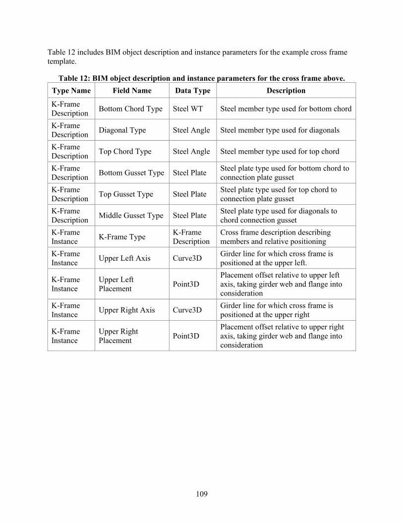
109
Table 12 includes BIM object description and instance parameters for the example cross frame template.
Table 12: BIM object description and instance parameters for the cross frame above. Type Name Field Name Data Type Description
K-Frame Description Bottom Chord Type Steel WT Steel member type used for bottom chord
K-Frame Description Diagonal Type Steel Angle Steel member type used for diagonals
K-Frame Description Top Chord Type Steel Angle Steel member type used for top chord
K-Frame Description Bottom Gusset Type Steel Plate Steel plate type used for bottom chord to
connection plate gusset K-Frame Description Top Gusset Type Steel Plate Steel plate type used for top chord to
connection plate gusset K-Frame Description Middle Gusset Type Steel Plate Steel plate type used for diagonals to
chord connection gusset K-Frame Instance K-Frame Type K-Frame
Description Cross frame description describing members and relative positioning
K-Frame Instance Upper Left Axis Curve3D Girder line for which cross frame is
positioned at the upper left.
K-Frame Instance
Upper Left Placement Point3D
Placement offset relative to upper left axis, taking girder web and flange into consideration
K-Frame Instance Upper Right Axis Curve3D Girder line for which cross frame is
positioned at the upper right
K-Frame Instance
Upper Right Placement Point3D
Placement offset relative to upper right axis, taking girder web and flange into consideration
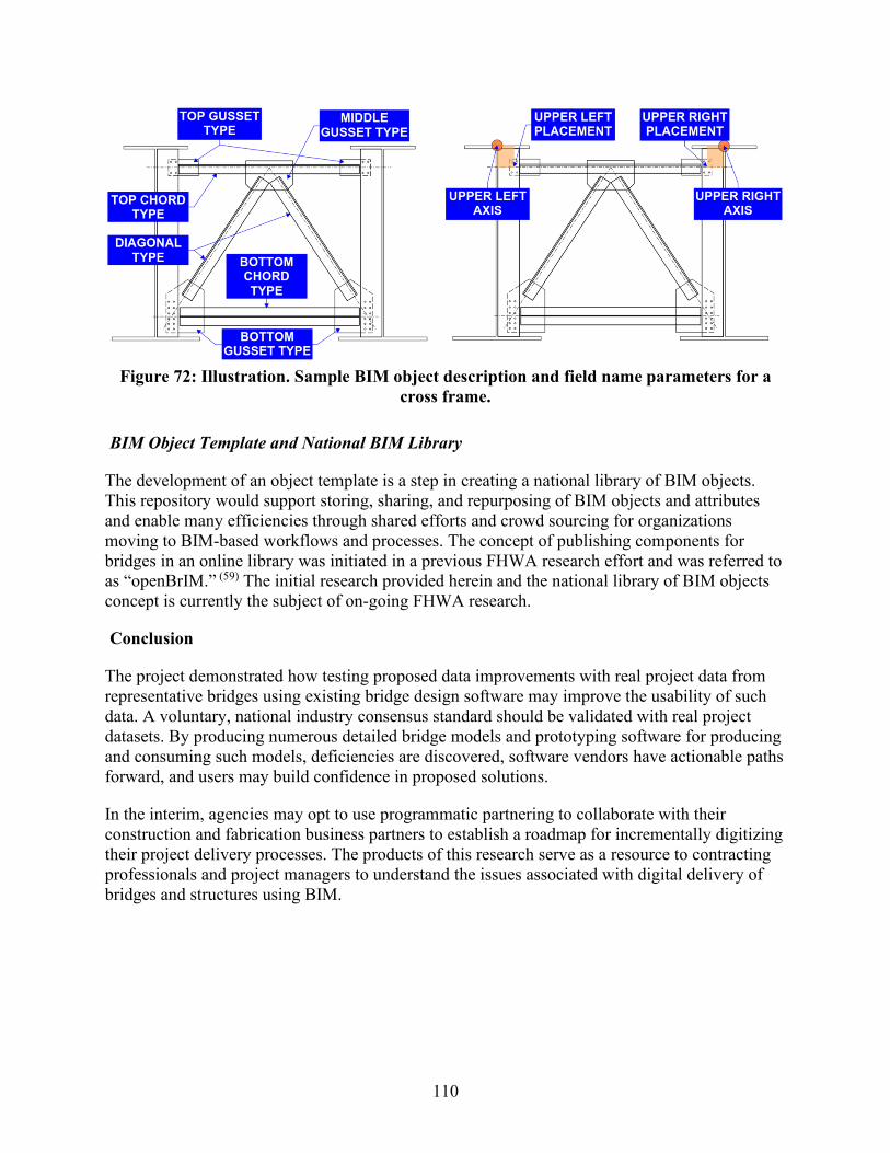
110
Figure 72: Illustration. Sample BIM object description and field name parameters for a
cross frame.
BIM Object Template and National BIM Library
The development of an object template is a step in creating a national library of BIM objects. This repository would support storing, sharing, and repurposing of BIM objects and attributes and enable many efficiencies through shared efforts and crowd sourcing for organizations moving to BIM-based workflows and processes. The concept of publishing components for bridges in an online library was initiated in a previous FHWA research effort and was referred to as “openBrIM.” (59) The initial research provided herein and the national library of BIM objects concept is currently the subject of on-going FHWA research.
Conclusion
The project demonstrated how testing proposed data improvements with real project data from representative bridges using existing bridge design software may improve the usability of such data. A voluntary, national industry consensus standard should be validated with real project datasets. By producing numerous detailed bridge models and prototyping software for producing and consuming such models, deficiencies are discovered, software vendors have actionable paths forward, and users may build confidence in proposed solutions.
In the interim, agencies may opt to use programmatic partnering to collaborate with their construction and fabrication business partners to establish a roadmap for incrementally digitizing their project delivery processes. The products of this research serve as a resource to contracting professionals and project managers to understand the issues associated with digital delivery of bridges and structures using BIM.

111
CHAPTER 8 REFERENCES
1. Cambridge Systematics, Inc., et al. XML Schemas for Exchange of Transportation Data.Medford, MA: Cambridge Systematics, Inc., 2006. NCHRP 20-64.
2. Messner, J., et al. Building Information Modeling Project Execution Planning Guide --Version 2.2. Computer Integrated Construction Research Program. University Park, PA: ThePennsylvania State University, 2019.
3. McGraw-Hill Construction. The Business Value of BIM for Owners. Bedford, MA: McGraw-Hill Construction, 2014.
4. International Organization for Standardization. ISO 16739:2013. Geneva, Switzerland: s.n.
5. McGraw-Hill Construction. The Business Value of BIM. Bedford, MA: McGraw-HillConstruction, 2009.
6. American Institute of Architects. Document E202™ – 2008 Instructions. AIA ContractDocuments. [Online] American Institute of Architects. [Cited: November 28, 2017.]http://contractdocs.aia.org:800/!SSL!/Multiscreen_HTML5/desktop/Get_Document_Answers/Document_Instruction_Sheets/By_Series/E-Series/E202-2008.htm.
7. ConsensusDocs. ConsensusDocs Guidebook 301 Building Information Modeling Addendum.Arlington, VA: ConsensusDocs, 2015.
8. Chen, S. S. and Shirole, A. M. Bridge Data File Protocols for Interoperability and Life CycleManagement. Washington, DC: Federal Highway Administration, 2013. FHWA-HIF-16-003.
9. International Collaboration for Developing the Bridge Product Model "IFC-Bridge". Yabuki,Nobuyoshi, et al. Montréal, Canada: s.n., 2006. Joint International Conference on Computingand Decision Making in Civil and Building Engineering. pp. 1927-1926.
10. Turnbull, Katherine F. The Future of TransXML Workshop Summary. Washington, DC:Transportation Research Board, 2014.
11. Chipman, Tim, et al. Bridge Information Model Standardization Report Volume I:Information Exchanges. Washington, DC: Federal Highway Administration, 2016.DTFH6114C00047.
12. Castaing, Christophe, et al. IFC Bridge Project Plan. s.l.: buildingSMART Infra Room,2017.
13. Mlynarski, Mark and Hu, Hanjin. Standardized Format for Bridge and Structure InformationModels. Moon Township, PA: Michael Baker International, 2016.
14. The IFC-Bridge Project - Extending the IFC Standard to Enable High-Quality Exchange ofBridge Information Models. Borrmann, André, et al. Chania, Crete, Greece: European Councilon Computing in Construction, 2019. 2019 European Conference on Computing in Construction.pp. 377-386.
112
15. National Cooperative Highway Research Program. Building Information Modeling (BIM) for Bridges and Structures. Transportation Pooled Fund. [Online] November 8, 2017. [Cited: December 18, 2017.] http://www.pooledfund.org/Details/Solicitation/1450.
16. Jernigan, Finith. BIG BIM little bim The Practical Approach to Building Information Modeling Integrated Practice done the right way! Second. Salisbury, MD: 4Site Press, 2009.
17. BIMe Initiative. BIM Dictionary. BIM Dictionary. [Online] Changeagents AEC, July 1, 2017. [Cited: January 25, 2018.] https://bimdictionary.com/.
18. Chatterton, Scott. The Four Approaches to BIM. The BIM Jedi. [Online] October 17, 2012. [Cited: January 25, 2018.] http://bim4scottc.blogspot.com/2012/10/the-four-approaches-to-bim.html.
19. National Institute of Building Sciences. IFC Bridge Design to Construction Information Exchange (U.S.). IFC Bridge Information Exchange (US). [Online] 2016. [Cited: 4 29, 2018.] http://docs.buildingsmartalliance.org/IFC4x2_Bridge/.
20. Utah Department of Transportation. Consultant Services Solicitation: I-80; Blackrock Structure Replacement, C-438. Salt Lake City, UT: Utah Department of Transportation, 2017.
21. Hacker, Darby. Structure No. C-1047 Type Selection Report. Salt Lake City, UT: Michael Baker International, 2017.
22. Utah Department of Transportation. Consultant Services Solicitation F-I80-3(186)102 I-80; Structure Replacement (MP 101 and 99). Salt Lake City, UT: Utah Department of Transportation, 2018.
23. Reasch, Lawrence R., Bowden, Wayne and Wells, Eric. Collaboration using the CM/GC Process to Find Solutions for Accelerated Bridge Construction. Salt Lake City, UT: Utah Department of Transportation, 2010.
24. Lukes, George and McDowell, Jim. Intelligent Design & Construction Guidance Document. Salt Lake City, UT: Utah Department of Transportation Preconstruction Division, 2017.
25. Utah Department of Transportation. Project Delivery Methods. Salt Lake City, UT: Utah Department of Transportation, 2018.
26. Kitteridge, Robert. Bridge Replacement for Structure C-583 Structure Type Selection Report. Salt Lake City, UT: HDR Inc., 2017.
27. HDR, Inc. BIM Software Usage for Federated Model Evaluation Report (Draft). Salt Lake City, UT: Utah Department of Transportation, 2017.
28. —. BrIM Model Authoring Execution Plan for I-80; Blackrock Structure Replacement, C-438. Omaha, NE: HDR, Inc., 2017.
29. US Army Corps of Engineers. Minimum Modeling Matrix (M3). [Spreadsheet] Washington, DC: s.n., 2014. Version 1.3.
113
30. HDR, Inc. UDOT_ModelProgressionBaseline. [Spreadsheet] Salt Lake City, UT: HDR, Inc.,2017.
31. Federal Highway Administration. Guide for 3D Engineered Models for Bridges andStructures. Washington, DC: Federal Highway Administration, 2017. FHWA-HIF-17-039.
32. Microdesk. Microdesk's ModelStream Selected By NYNJ Link For BIM To AssetManagement Integration. PR Newswire. [Online] April 13, 2016. [Cited: January 25, 2018.]https://www.prnewswire.com/news-releases/microdesks-modelstream-selected-by-nynj-link-for-bim-to-asset-management-integration-300250963.html.
33. Port Authority of NY & NJ. E/A Design Division BIM Standard Manual. Newark, NJ: PortAuthority of NY & NJ, 2012.
34. Thomas, Larry W. and McDaniel, James B. Legal Issues Surrounding the Use of DigitalIntellectual Property on Design and Construction Projects. Washington, DC: NationalCooperative Highway Research Program, 2013. Legal Research Digest 58.
35. Florida Department of Transportation. e-Construction How-to Guide. Tallahassee, FL:Florida Department of Transportation, 2015. Version 2.3.
36. New York State Department of Transportation. NYSDOT Bridge Manual. Albany, NY: NewYork State Department of Transportation, 2017.
37. WSP | Parsons Brinckerhoff. Development of 3D and 4D Bridge Models and Plans Phase IIReport. Lansing, MI: Michigan Department of Transportation, 2017.
38. BIMForum. Level of Development Specification Part 1. s.l.: BIMForum, 2019.
39. National Institute of Building Sciences. National BIM Guide for Owners. Washington, DC:National Institute of Building Sciences, 2017.
40. Chipman, Tim, et al. Bridge Information Modeling Standardization – Report Introduction.Washington, DC: Federal Highway Administration, 2016. DTFH6114C00047.
41. American Instutute of Architects. AIA Contract Documents. Integrated Project Delivery(IPD) Family. [Online] American Institute of Architects, 2018. [Cited: January 25, 2018.]https://www.aiacontracts.org/contract-doc-pages/27166-integrated-project-delivery-ipd-family.
42. Pennsylvania State University. Building Information Modeling (BIM) Universal Addendum.Office of the Physical Plant. State College, PA: Pennsylvania State University, 2017. Version3.2.
43. New York State Department of Transportation. Kosciuszko Bridge Project - Phase 1 ContractDocuments Part 3 Project Requirements. New York State Department of Transportation. [Online]Aug 27, 2013. [Cited: Jun 22, 2016.]https://www.dot.ny.gov/portal/page/portal/content/delivery/region11/projects/X72977-Home/X72977-Repository/K-Bridge%20-%20Part%203%20-%20Project%20Requirements.pdf.

114
44. BIM There, Done That: Creating Contracts that Captialize on New Technology. Yand, James and O'Hanlon, Tara. [ed.] Marc Ramsey. August 2013, Alexandria, VA: American Subcontractor's Association, Inc., 2013, The Contractor's Compass, pp. 18-20.
45. Tynan, Jim, et al. Guide Specifications for Highway Construction. Washington, DC: American Association of State Highway and Transportation Officials, 2008. GSH-08.
46. Utah Department of Transportation. Special Provisions & Supplemental Specifications Project # F-0020(10)10. Salt Lake City, UT: Utah Department of Transportation, 2016.
47. Loulakis, Michael C., et al. Liability of Design-Builders for Design, Construction, and Acquisition Claims. National Cooperative Highway Research Program, National Academies of Science. Washington, DC: Transportation Research Board, 2015. Legal Research Digest. Legal Research Digest 68.
48. Virginia Department of Transportation. General Conditions of Contract Between Department and Design-Builder. Richmond, VA: Virginia Department of Transportation, 2009.
49. Maier, Francesca, et al. Automation in Highway Construction Part II: Design Guidance and Guide Specification Manual. Washington, DC: Federal Highway Administration, 2016.
50. AASHTO. AASHTOWare Bridge. AASHTOWare. [Online] [Cited: 03 09, 2018.] http://www.aashtoware.org/Bridge/Pages/default.aspx.
51. BuildingSmart International. Industry Foundation Classes. BuildingSmart International. [Online] [Cited: 03 09, 2018.] http://www.buildingsmart-tech.org/ifc. ISO 16739-1.
52. IfcKit GitHub repository. GitHub. [Online] BuildingSmart. [Cited: 03 09, 2018.] https://github.com/BuildingSMART/IfcDoc/tree/master/IfcKit.
53. National Institute of Building Sciences. Bridge Information Exchange. [Online] 2016. http://www.nibs.org/?page=bsa_bridgeie.
54. International Organization for Standardization. ISO/PAS 17506:2012. Standards Catalogue. [Online] 2015. [Cited: August 4, 2019.] https://www.iso.org/standard/59902.html.
55. Bartholomew, Michael, Blasen, Benjamin and Koc, Ali. Bridge Information Modeling (BrIM) Using Open Parametric Objects. Washington, DC: Federal Highway Administration, 2015.
56. Utah Department of Transportation. 3D Engineered Models for Construction Implementation Plan. Salt Lake City, UT: Utah Department of Transportation, 2014.
57. Roadway Design Office. Chapter 19 Signing and Sealing Documents. [book auth.] Florida Department of Transportation. Plans Preparation Manual. Talahassee, FL: Florida Department of Transportation, 2017, Vol. 1.
58. New York State Thruway Authority. Building Information Modeling Using 3D Technology to Build the New Bridge. The New NY Bridge. [Online] New York State Thruway Authority,
115
September 18, 2015. [Cited: January 31, 2018.] http://www.newnybridge.com/building-information-modeling-using-3d-technology-to-build-the-new-bridge/.
59. New York State Department of Transportation. Standards Specifications (US Customary Units). Albany, NY: State of New York Department of Transportation, 2014.
60. Nevada Department of Transportation. Standard Specifications for Road and Bridge Construction. Carson City, NV: Nevada Department of Transportation, 2014.
61. Michigan Department of Transportation. MDOT Digital Signature Certificate Request Form. Digital Signatures with MDOT. [Online] May 16, 2017. [Cited: January 28, 2018.] https://mdotjboss.state.mi.us/webforms/GetDocument.htm?fileName=2122.pdf.
62. Iowa Department of Transportation. Special Provisions for Conformity with and Coordination of the Contract Documents. Ames, IA: Iowa Department of Transportation, 2015. SP- 120279.
63. —. Design Manual. Ames, IA, USA: s.n.
64. International Organization for Standardization. ISO 12006-2:2015. Standards catalog | Publications and products. [Online] 2015. [Cited: February 8, 2018.] https://www.iso.org/standard/61753.html.
65. International Partnering Institute. Partnering 101 An Introduction to Partnering. International Partnering Institute. [Online] April 7, 2014. [Cited: January 25, 2018.] http://partneringinstitute.org/wp-content/uploads/2013/10/IPI-101.pdf.
66. Florida Department of Transportation. SCOPE OF THE WORK - INTENT OF CONTRACT. Implemented Modifications to the 2015 Standard Specifications July 2015 Workbook. [Online] July 2015. [Cited: January 28, 2018.] http://www.fdot.gov/programmanagement/Implemented/Workbooks/JulWorkbook2015/Files/SP0040100ES.pdf. SP0040100ES.
67. Federal Highway Administration. 3D Engineered Models for Construction Webinar Series Summary. EDC 2 3D Engineered Models Webinar Series. [Online] February 12, 2015. [Cited: January 26, 2018.] https://www.fhwa.dot.gov/construction/3d/webinars/summary.pdf.
68. California Department of Transportation. Standard Specifications. Sacramento, CA: State of California, 2015.