DEMO - 1964 Ford Truck Shop Manual (100-350 Series)
42
-
Upload
khangminh22 -
Category
Documents
-
view
0 -
download
0
Transcript of DEMO - 1964 Ford Truck Shop Manual (100-350 Series)
Demo
Demo Sample
This DEMO contains only a few pages of the entire manual/product. Not all Bookmarks work on the Demo but they do on the full version. Features: - Searchable text - Printable pages - Bookmarked for easy navigation - High Resolution images - Zoom to see exact details - Money back Guarantee

Copyright © 2011, Forel Publishing Company, LLC, Woodbridge, Virginia
All Rights Reserved. No part of this book may be used or reproduced in any manner whatsoever without written permission of Forel Publishing Company, LLC. For information write to Forel
Publishing Company, LLC, 3999 Peregrine Ridge Ct., Woodbridge, VA 22192
1964 Ford Truck Shop Manual (100-350 Series) EAN: 978-1-60371-072-5
ISBN: 1-60371-072-8
Forel Publishing Company, LLC 3999 Peregrine Ridge Ct. Woodbridge, VA 22192
Email address: [email protected] Website: http://www.ForelPublishing.com
This publication contains material that is reproduced and distributed under a license from Ford Motor Company. No further reproduction or distribution of the Ford Motor Company material is
allowed without the express written permission of Ford Motor Company.
Note from the Publisher This product was created from the original Ford Motor Company’s publication. Every effort has been made to use the original scanned images, however, due to the condition of the material; some pages have been modified to remove imperfections.
Disclaimer
Although every effort was made to ensure the accuracy of this book, no representations or warranties of any kind are made concerning the accuracy, completeness or suitability of the information, either expressed or implied. As a result, the information contained within this book should be used as general information only. The author and Forel Publishing Company, LLC shall have neither liability nor responsibility to any person or entity with respect to any loss or damage caused, or alleged to be caused, directly or indirectly by the information contained in this book. Further, the publisher and author are not engaged in rendering legal or other professional services. If legal, mechanical, electrical, or other expert assistance is required, the services of a competent professional should be sought.


FOREWORD
This shop manual provides the Service Technician with com
plete information for the proper servicing of the 1964
F-100-350 & P-Series Trucks.
The information is grouped according to the type of work
being performed, such as diagnosis and testing, frequently
performed adjustments and repairs, in-vehicle adjustments,
overhaul, etc. Specifications, maintenance information and
recommended special tools are included.
Refer to the opposite page for important vehicle identifica
tion data.
The descriptions and specifications in this manual were in
effect at the time this manual was approved for printing. The
Ford Motor Company reserves the right to discontinue models
at any time, or change specifications or design, without notice
and without incurring obligation.
SERVICE DEPARTMENT
FORD MOTOR COMPANY
FORD TRUCK IDENTIFICATION
TRUCK IDENTIFICATION
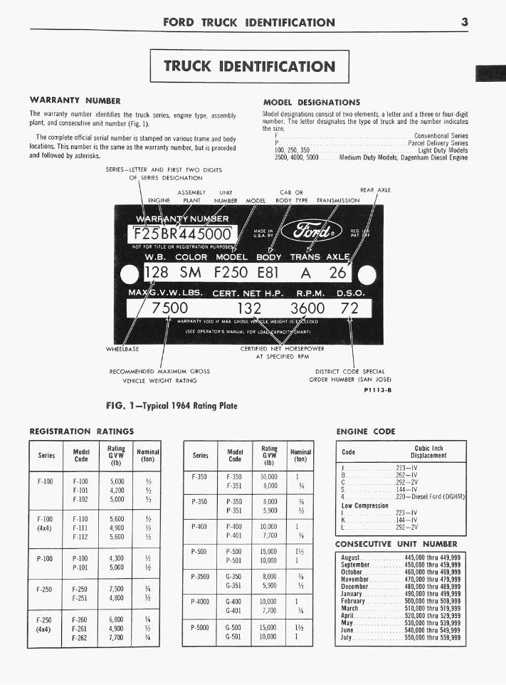
WARRANTY NUMBER
The warranty number identifies the truck series, engine type, assembly plant, and consecutive unit number (Fig. 1).
The complete official serial number is stamped on various frame and body locations. This number is the same as the warranty number, but is preceded and followed by asterisks.
SERIES-LETTER AND FIRST TWO DIGITS
OF SERIES DESIGNATION
ASSEMBfY
ENGINE PLANT
25BR445000
MODEL DESIGNATIONS
Model designations consist of two elements, a letter and a three or four-digit number. The letter designates the type of truck and the number indicates the size.
F Conventional Series P Parcel Delivery Series 100, 250, 350 Light Duty Models 3500, 4000, 5000 Medium Duty Models, Dagenham Diesel Engine
ER /
NOT FOR TITLE OR REGISTRATION PURPOSES^
W.B. COLOR MODEL BODY TRANS AXLE/
128 S M F250 E81 A 26 .V.W.LBS. CERT. NET H.P. R.P.M. D.S.O.
7500 WARRANTY VOID IF MAX. GROSS Vt
{SEE OPERATOR'S MANUAL FOR LOAD
CERTIFIED NET HORSEPOWER
AT SPECIFIED RPM
RECOMMENDED MAXIMUM GROSS
VEHICLE WEIGHT RATING
DISTRICT CODE SPECIAL
ORDER NUMBER (SAN JOSE)
P1U3-B
FIG. 1-Typical 1964 Rating Plate
REGISTRATION RATINGS ENGINE CODE
Series
F-100
F-100
(4x4)
P-100
F-250
F-250
(4x4)
Model Code
F-100
F-101
F-102
F-110
Fill
F-112
P-100
P-101
F-250
F-251
F-260
F-261
F-262
Rating GVW (lb)
5,000
4,200
5,000
5,600
4,900
5,600
4,300
5,000
7,500
4,800
6,800
4,900
7,700
Nominal (ton)
lA Vi
1/2
Vi
Vi lA
lA
Vi
3/4 lA 3/4
Series
F-350
P-350
P-400
P-500
P-3500
P-4000
P-5000
Model Code
F-350
F-351
P-350
P-351
P-400
P-401
P-500
P-501
G-350
G-351
G-400
G-401
G-500
6-501
Rating GVW (lb)
10,000
8,000
8,000 5,900
10,000
7,700
15,000
10,000
8,000
5,900
10,000
7,700
15,000
10,000
Nominal (ton)
1
1 !/4
VA 1
Vi
1
VA 1
Code Cubic Inch Displacement
J 223—IV B 262—IV C 292-2V S 144—IV 4 220—Diesel Ford (DGHM) Low Compression 1 223—IV K 144—IV L 292-2V
CONSECUTIVE UNIT NUMBER
August 445,000 thru 449,999 September 450,000 thru 459,999 October 460,000 thru 469,999 November 470,000 thru 479,999 December 480,000 thru 489,999 January 490,000 thru 499,999 February 500,000 thru 509,999 March 510,000 thru 519,999 April 520,000 thru 529,999 May 530,000 thru 539,999 June 540,000 thru 549,999 July 550,000 thru 559,999
4 FORD TRUCK IDENTIFICATION
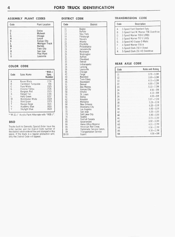
ASSEMBLY PLANT CODES DISTRICT CODE TRANSMISSION CODE
Code
D E G H K L N P R S U
COLOR
Code
A B C G J K L M S T V Y
CODE
Sales Name
Raven Black Caribbean Turq Pure White Chrome Yellow Rangoon Red Bengal Tan Holly Green
Plant Location
Dallas Mahwah Chicago Lorain Kansas City Michigan Norfolk Twin City San lose
Truck
Pilot Plant Louisville
M30-J Spec.
Number
uoise
Wimbledon White Mint Green Navajo Beige Academy Blue Skylight Blue
1724 556 1525 1526 1515 1706 1237 1619 1373 1631 1024 1623
"M-32-J" Acrylic Paint Alternate with "M30-J"
DSO
Trucks built to Domestic Special Order have the order number and the District Code number ot the district which ordered the unit stamped in this space. If the truck is a regular production unit, only the District Code will appear.
Code District
11 12 13 14 15 21 22 23 24 25 26 31 32 33 34 35 36 41 42 43 44 45 51 52 53 54 55 61 62 63 64 65 71 72 73 74 81 83 84 85 86 89
0-99
Boston Buffalo New York Pittsburgh Newark Atlanta Charlotte Philadelphia Jacksonville Richmond Washington Buffalo Cleveland Detroit Indianapolis Lansing Louisville Chicago Fargo Rockford Twin Cities Davenport Denver Des Moines Kansas City Omaha St. Louis Dallas Houston Memphis New Orleans Oklahoma City Los Angeles San Jose Salt Lake City Seattle Ford of Canada Government Home Office Reserve American Red Cross Diplomatic Service Comm Transportation Service Export
Code Description
A 3-Speed Ford Standard Duty
B 3
D 3
E 3
G 3
F 4
J 5
Speed Ford W Warner T86 Overdrive
Speed Warner T89-C (MD)
Speed Warner T87-E (HD)
Speed HD Cruise-O-Matic
Speed Warner T98-A
Speed Clark 250-V Direct
K 5-Speed Clark 251-VO Overdrive
REAR AXLE CODE
Code
11
12
13
22
23
24
25
26
29
30
32
34
42
44
Al
A2
A3
A4
A5
B4
Ratio and Rating
3.70-3.3M
3.89-3.3M
4.11-3.3M
4.8S-7.2M
5.13-7.2M
4.56-5M
4.10-5M 4.88-5M
5.87-7.2M
5.29-11M
6.20-11M
6.80—11M
6.20-13M 6.80-13M
3.73-3.3M
3.92-3.3M
4.11-2.7M
4.56-2.7M
4.10-2.7M
4.56-5M
2-1
BRAKES GROUP 2
PART 2-1 GENERAL BRAKE SERVICE
PART 2-2 F- AND P-100 SERIES BRAKE SYSTEMS
PAGE 2-1
2-8
PART 2-3 F-250, F-350, AND P-SERIES BRAKE SYSTEMS
PART 2-4 SPECIFICATIONS
PAGE
2-16
2-35
PART 2-1
GENERAL BRAKE SERVICE
Section Page
1 Diagnosis and Testing 2-2
2 C o m m o n Adjustments and Repairs 2-5
Section
3 Cleaning and Inspection
Page
. .2-6
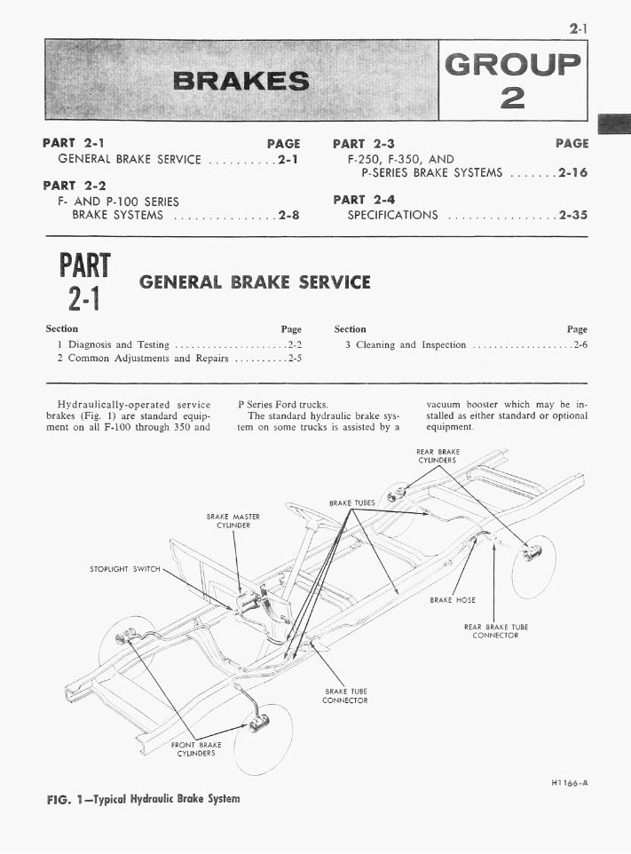
Hydraulically-operated service brakes (Fig. 1) are standard equipment on all F-100 through 350 and
P Series Ford trucks. The standard hydraulic brake sys
tem on some trucks is assisted by a
vacuum booster which may be installed as either standard or optional equipment.
REAR BRAKE CYLINDERS
BRAKE MASTER CYLINDER
STOPLIGHT SWITCH
FIG. 1 —Typical Hydraulic Brake System
H1166-A

2-2 G R O U P 2-BRAKES
Q DIAGNOSIS AND
The trouble shooting symptoms, causes, and corrections given in the following diagnosis guide apply to all truck hydraulic brakes including those with a vacuum booster.
PRELIMINARY CHECKS-STANDARD HYDRAULIC SYSTEM
Push the brake pedal down as far
DIAGNOSIS GUIDE—STANDARD
BRAKES DO NOT APPLY
EXCESSIVE PEDAL TRAVEL
UNEVEN, NOISY, GRABBING, OR HARD OPERATING BRAKES
BRAKES DO NOT RELEASE
TESTING
as it will go. If the pedal travels
more than halfway between the re
leased position and the floor, adjust
the brakes.
Road test the truck and apply the
brakes at a speed of about 20 m p h
to see if the truck stops evenly. If
not, the brakes should be adjusted.
Perform the road test only when the
HYDRAULIC BRAKES
If the brake pedal travels all the way down to the floor without noticeable brake action, check the brake fluid level in the master cylinder reservoir. Refill the reservoir if necessary. Check the entire hydraulic system for fluid leaks, and make the necessary adjustments.
If the brake pedal feels spongy when pushed down, air has entered the hydraulic lines. Air can enter the lines if the fluid level in the master cylinder reservoir is too low, or if the brake wheel cylinder pistons are not held firmly in place when the brake
Check for air in the brake lines and bleed the system if necessary.
Remove the brake drums so that a complete inspection of the brake assemblies can be made to determine the cause of the trouble.
Excessive dust and dirt in the brake lining rivet holes or in the brake drum can cause brake squeal. Remove the dirt with a scraper and an air hose.
Drums which are out-of-round or loose at the hub; frozen master cylinder or brake cylinder piston(s); defective check valve; improper
Check for an improperly adjusted brake pedal, a restricted by-pass port in the master cylinder, or swollen master cylinder piston cups. Check for a defective check valve restricting fluid passing through the system. Check for sticking brake cylinder pistons caused by dirty or contaminated brake fluid.
Adjust the brake pedal if necessary. If the adjustment does not correct the trouble, check the condition of the brake fluid. Replace dirty or contaminated fluid. Clean the entire
brakes will apply and the truck can be safely stopped.
Apply steady pressure to the brake pedal. If it moves slowly toward the floor, check for leaks in the master cylinder, brake cylinders, or elsewhere in the hydraulic system (Fig. 1). If the brake pedal feels spongy, bleed the system to remove air from the lines.
shoes are serviced. A defective check valve can cause a loss of residual pressure in the system causing air to enter at the wheel cylinder piston. Bleed the system to remove air from the lines, and adjust the brakes. Refill the master cylinder reservoir with heavy-duty brake fluid. If the brakes do not apply after making these checks and adjustments, fluid may be leaking past the piston cups in the master cylinder or brake wheel cylinder^). If the trouble is in the master cylinder or brake wheel cylin-der(s), remove and repair.
Adjust or reline the brakes as needed.
brake shoe adjustment; warped or misaligned shoes; webs glazed or greasy linings; and incorrectly ground or wrong linings, are a few of the causes for uneven, noisy, pulling. grabbing, or hard brakes. Adjust or replace the parts as needed to eliminate the trouble. Lining glaze can be removed by rubbing the lining with medium-grade sandpaper until the lining has a dull finish. Always adjust the brakes after correcting any of these brake troubles.
hydraulic system with clean denatured alcohol before adding new brake fluid.
If the trouble is in the master cylinder, remove and rebuild the cylinder.
If the truck must be moved when the brakes are locked, open a brake cylinder bleeder screw for a moment to let out a few drops of brake fluid. This operation will release the brakes but will not eliminate the cause of the trouble.
CONTINUED ON NEXT PAGE
P A R T 2-1-GENERAL BRAKE SERVICE 2-3
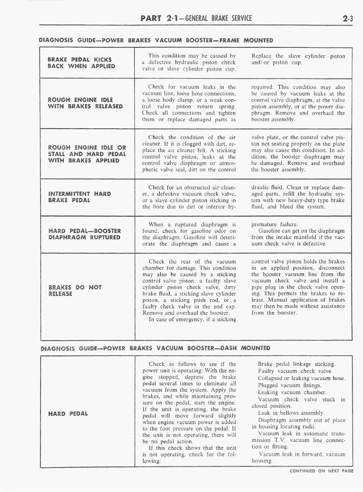
DIAGNOSIS GUIDE—POWER BRAKES VACUUM BOOSTER—FRAME MOUNTED
BRAKE PEDAL KICKS BACK WHEN APPLIED
ROUGH ENGINE IDLE WITH BRAKES RELEASED
ROUGH ENGINE IDLE OR STALL AND HARD PEDAL WITH BRAKES APPLIED
INTERMITTENT HARD BRAKE PEDAL
HARD PEDAL—BOOSTER DIAPHRAGM RUPTURED
BRAKES DO NOT RELEASE
This condition may be caused by Replace the slave cylinder piston a defective hydraulic piston check and/or piston cup. valve or slave cylinder piston cup.
Check for vacuum leaks in the required. This condition may also vacuum line, loose hose connections, be caused by vacuum leaks at the a loose body clamp, or a weak con- control valve diaphragm, at the valve trol valve piston return spring. piston assembly, or at the power dia-Check all connections and tighten phragm. Remove and overhaul the them or replace damaged parts as booster assembly.
Check the condition of the air valve plate, or the control valve pis-cleaner. If it is clogged with dirt, re- ton not seating properly on the plate place the air cleaner felt. A sticking may also cause this condition. In ad-control valve piston, leaks at the dition, the booster diaphragm may control valve diaphragm or atmos- be damaged. Remove and overhaul pheric valve seal, dirt on the control the booster assembly.
Check for an obstructed air clean- draulic fluid. Clean or replace darner, a defective vacuum check valve, aged parts, refill the hydraulic sys-or a slave cylinder piston sticking in tem with new heavy-duty type brake the bore due to dirt or inferior hy- fluid, and bleed the system.
When a ruptured diaphragm is premature failure. found, check for gasoline odor on Gasoline can get on the diaphragm the diaphragm. Gasoline will deteri- from the intake manifold if the vac-orate the diaphragm and cause a uum check valve is defective.
Check the rear of the vacuum control valve piston holds the brakes chamber for damage. This condition in an applied position, disconnect may also be caused by a sticking the booster vacuum line from the control valve piston, a faulty slave vacuum check valve and install a cylinder piston check valve, dirty pipe plug in the check valve open-brake fluid, a sticking slave cylinder ing. This permits the brakes to re-piston, a sticking push rod, or a lease. Manual application of brakes faulty check valve in the end cap. may then be made without assistance Remove and overhaul the booster. from the booster.
In case of emergency, if a sticking
DIAGNOSIS GUIDE—POWER BRAKES VACUUM BOOSTER—DASH MOUNTED
H A R D PEDAL
Check as follows to see if the Brake pedal linkage sticking. power unit is operating: With the en- Faulty vacuum check valve. gine stopped, depress the brake Collapsed or leaking vacuum hose. pedal several times to eliminate all Plugged vacuum fittings vacuum from the system. Apply the Ud^Qg v a c u u m c h a m b e r
brakes, and while maintaining pres- ,r , . , , , , . ., ° . Vacuum check valve stuck in
sure on the pedal, start the engine. , , ., . y . , ,b , closed position. If the unit is operating, the brake , , - , , , pedal will move forward slightly Leak ,n bellows assembly. when engine vacuum power is added Diaphragm assembly out of place to the foot pressure on the pedal. If ln housing locating radii: the unit is not operating, there will Vacuum leak in automatic trans-be no pedal action. mission T.V. vacuum line connec-
If this check shows that the unit tion or fitting. is not operating, check for the fol- Vacuum leak in forward, vacuum lowing: housing. CONTINUED ON NEXT PAGE
2-4 G R O U P 2-BRAKES
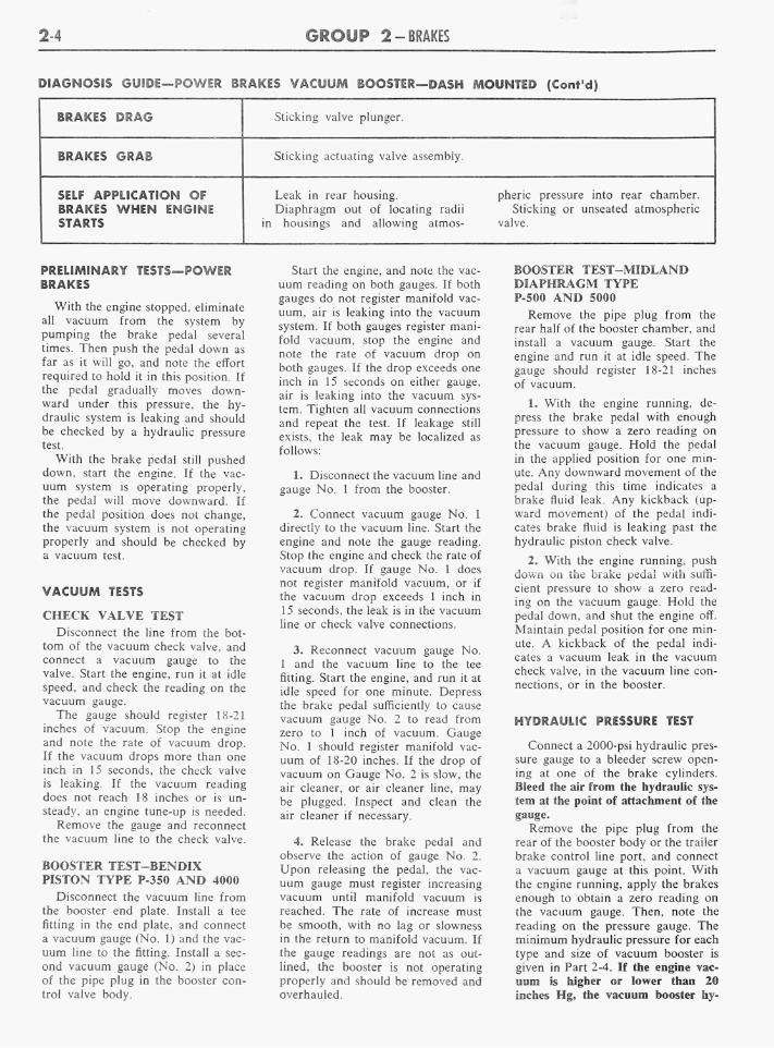
DIAGNOSIS GUIDE—POWER BRAKES VACUUM BOOSTER—DASH MOUNTED (Cont'd)
BRAKES DRAG
BRAKES GRAB
SELF APPLICATION OF BRAKES WHEN ENGINE STARTS
Sticking valve plunger.
Sticking actuating valve assembly.
Leak in rear housing. pheric pressure into rear chamber. Diaphragm out of locating radii Sticking or unseated atmospheric
in housings and allowing atmos- valve.
PRELIMINARY TESTS—POWER BRAKES
With the engine stopped, eliminate all vacuum from the system by pumping the brake pedal several times. Then push the pedal down as far as it will go, and note the effort required to hold it in this position. If the pedal gradually moves downward under this pressure, the hydraulic system is leaking and should be checked by a hydraulic pressure test.
With the brake pedal still pushed down, start the engine. If the vacu u m system is operating properly, the pedal will move downward. If the pedal position does not change, the vacuum system is not operating properly and should be checked by a vacuum test.
VACUUM TESTS
CHECK VALVE TEST Disconnect the line from the bot
tom of the vacuum check valve, and connect a vacuum gauge to the valve. Start the engine, run it at idle speed, and check the reading on the vacuum gauge.
The gauge should register 18-21 inches of vacuum. Stop the engine and note the rate of vacuum drop. If the vacuum drops more than one inch in 15 seconds, the check valve is leaking. If the vacuum reading does not reach 18 inches or is unsteady, an engine tune-up is needed.
Remove the gauge and reconnect the vacuum line to the check valve.
BOOSTER TEST-BENDIX PISTON TYPE P-350 AND 4000 Disconnect the vacuum line from
the booster end plate. Install a tee fitting in the end plate, and connect a vacuum gauge (No. 1) and the vacu u m line to the fitting. Install a second vacuum gauge (No. 2) in place of the pipe plug in the booster control valve body.
Start the engine, and note the vacu u m reading on both gauges. If both gauges do not register manifold vacuum, air is leaking into the vacuum system. If both gauges register manifold vacuum, stop the engine and note the rate of vacuum drop on both gauges. If the drop exceeds one inch in 15 seconds on either gauge, air is leaking into the vacuum system. Tighten all vacuum connections and repeat the test. If leakage still exists, the leak may be localized as follows:
1. Disconnect the vacuum line and gauge No. 1 from the booster.
2. Connect vacuum gauge No. 1 directly to the vacuum line. Start the engine and note the gauge reading. Stop the engine and check the rate of vacuum drop. If gauge No. 1 does not register manifold vacuum, or if the vacuum drop exceeds 1 inch in 15 seconds, the leak is in the vacuum line or check valve connections.
3. Reconnect vacuum gauge No. 1 and the vacuum line to the tee fitting. Start the engine, and run it at idle speed for one minute. Depress the brake pedal sufficiently to cause vacuum gauge No. 2 to read from zero to 1 inch of vacuum. Gauge No. 1 should register manifold vacuum of 18-20 inches. If the drop of vacuum on Gauge No. 2 is slow, the air cleaner, or air cleaner line, may be plugged. Inspect and clean the air cleaner if necessary.
4. Release the brake pedal and observe the action of gauge No. 2. Upon releasing the pedal, the vacu u m gauge must register increasing vacuum until manifold vacuum is reached. The rate of increase must be smooth, with no lag or slowness in the return to manifold vacuum. If the gauge readings are not as outlined, the booster is not operating properly and should be removed and overhauled.
BOOSTER TEST-MIDLAND DIAPHRAGM TYPE P-500 AND 5000
Remove the pipe plug from the rear half of the booster chamber, and install a vacuum gauge. Start the engine and run it at idle speed. The gauge should register 18-21 inches of vacuum.
1. With the engine running, depress the brake pedal with enough pressure to show a zero reading on the vacuum gauge. Hold the pedal in the applied position for one minute. Any downward movement of the pedal during this time indicates a brake fluid leak. Any kickback (upward movement) of the pedal indicates brake fluid is leaking past the hydraulic piston check valve.
2. With the engine running, push down on the brake pedal with sufficient pressure to show a zero reading on the vacuum gauge. Hold the pedal down, and shut the engine off. Maintain pedal position for one minute. A kickback of the pedal indicates a vacuum leak in the vacuum check valve, in the vacuum line connections, or in the booster.
HYDRAULIC PRESSURE TEST
Connect a 2000-psi hydraulic pressure gauge to a bleeder screw opening at one of the brake cylinders. Bleed the air from the hydraulic system at the point of attachment of the gauge.
Remove the pipe plug from the rear of the booster body or the trailer brake control line port, and connect a vacuum gauge at this point. With the engine running, apply the brakes enough to obtain a zero reading on the vacuum gauge. Then, note the reading on the pressure gauge. The minimum hydraulic pressure for each type and size of vacuum booster is given in Part 2-4. If the engine vacu u m is higher or lower than 20 inches Hg, the vacuum booster hy-

P A R T 2-1-GENERAL BRAKE SERVICE 25
draulic pressure will be proportionately higher or lower than the pressure given in Part 2-4.
Hold the brakes in the fully-
BRAKE PEDAL ADJUSTMENT
W h e n the brake pedal free-travel, which is the movement of the brake pedal before the push rod touches the master cylinder piston, is less than 3/i8 inch or more than 3/s inch (Fig. 2), the pedal should be adjusted.
!. Push the brake pedal down by hand pressure, and check the free travel.
2. Loosen the lock nut on the eccentric bolt, and rotate the eccentric bolt until the free travel is within 3/ia-% inch.
O n a P-Series truck, turn the hex head of the push rod to obtain the required free-travel.
3. Hold the bolt securely, and torque the lock nut to 30-35 ft-lbs.
4. Recheck the pedal free-travel to make sure that the adjustment did not change when the lock nut was tightened.
HYDRAULIC SYSTEM BLEEDING
When any part of the hydraulic system (Fig. 1) has been disconnected for repair or replacement, air may get into the lines and cause spongy pedal action. This requires the bleeding of the hydraulic system after it has been properly connected, to be sure all air is expelled from the brake cylinders and lines. The hy-
BRAKE PEDAL FREE TRAVEL HI Oil-A
FIG. 2—Pedal Free Travel Check
applied position for at least one minute, and note the reading on the pressure gauge. The hydraulic system should hold pressure for at least
draulic system can be bled manually or with pressure bleeding equipment.
' When bleeding the brake system, Meed one brake cylinder at a time beginning at the cylinder with the longest hydraulic line. If the brake assembly is equipped with two cylinders, always bleed the upper cylinder first. Keep the master cylinder
y reservoir filled with new heavy-duty e brake fluid during the bleeding op
eration. Never use brake fluid which has been drained from the hydraulic system.
n If the hydraulic system is equipped with a vacuum booster, bleed the
x hydraulic section of the booster be-e fore bleeding the rest of the hydrau
lic system. The bleeding operation must be done with the engine off and with no vacuum in the system.
3.
To bleed the hydraulic section of ;' a vacuum booster, follow steps 1 d through 4 of the manual bleeding IS procedure, attaching the drain tube
to the bleeder screw at the end plate of the booster (or the bleeder screw
} nearest the power chamber). Repeat this procedure at the other bleeder
lc screw if the booster is so equipped. 1-ir MANUAL BLEEDING
1. Attach a rubber drain tube to the bleeder screw of the brake wheel
, cylinder. The end of the tube should fit snugly around the bleeder screw.
/- 2. Submerge the free end of the tube in a container partially filled with clean brake fluid. Loosen the bleeder screw.
3. Push the brake pedal down slowly by hand, close the bleeder screw, then allow the pedal to return slowly to the fully-released position. Repeat this operation until air bubbles cease to appear at the submerged
i end of the tube.
4. W h e n the fluid is completely free of air bubbles, close the bleeder screw and remove the drain tube.
5. Repeat this procedure at each brake cylinder. Refill the master cyl-
A inder reservoir after each brake cylinder is bled and when the bleeding operation is completed.
one minute without losing pressure. A low pressure reading or a drop in pressure, indicates leakage in the booster or in the hydraulic system.
P R E S S U R E B L E E D I N G
Be sure that the tank is clean, that there is enough new heavy-duty brake fluid in the bleeder tank to complete the bleeding operation and that the tank is charged with 10-30 pounds of air pressure.
1. Clean all dirt from around the filler hole on the top of the master cylinder reservoir, and attach the bleeder tank hose to the filler hole.
2. Attach a rubber drain tube to the bleeder screw of the brake cylinder. The end of the tube should fit snugly around the bleed screw.
3. Submerge the free end of the tube in a container partially filled with clean brake fluid, and then loosen the bleeder screw.
4. Open the valve on the bleeder tank to admit pressurized brake fluid to the master cylinder reservoir (or line).
5. When air bubbles cease to appear in the fluid at the submerged end of the drain tube, close the bleeder screw and remove the tube.
6. Repeat this procedure at each brake cylinder.
7. W h en the bleeding operation is completed, close the bleeder tank valve and remove the tank hose from the filler hole.
8. Refill the master cylinder reservoir to within 3/» inch from the top of the filler neck.
WHEEL CYLINDER REPLACEMENT OR REPAIR
REPLACEMENT 1. Remove the wheel, drum, and
brake shoes. Remove the cylinder-to-shoe connecting links.
2. Disconnect the brake line from the brake cylinder. O n mucks equipped with a vacuum or air booster, be sure the engine is stopped and there is no vacuum or air pressure in the system before disconnecting the hydraulic lines.
3. Remove the brake cylinder retaining bolts and lockwashers, and then remove the cylinder from the carrier plate. O n the two-cylinder
| COMMON ADJUSTMENTS AND REPAIRS

2-6 GROUP 2-BRAKES
kit is used install all of the parts supplied in the kit.
BRAKE DRUM REFINISHING
Minor scores on a brake drum can be removed with fine emery cloth, provided the emery is thoroughly cleaned off the drum after the operation.
A badly scored, rough, or out-of-round drum should be ground or turned on a drum lathe. D o not remove any more material from the drum than is necessary to provide a smooth surface for the brake shoe contact. The refinished diameter should not be more than 0.060 inch oversize. For original brake drum sizes, see Part 2-4 Specifications.
If the diameter of the drum is less than 0.030 inch oversize after refin-ishing. install standard linings on the brake assemblies. If the diameter is over 0.030 inch, install oversize or shimmed linings.
BRAKE SHOE RELINING
1. Remove the rivets and remove the old lining.
2. Clean the shoe thoroughly with cleaning fluid, especially the rim surface. Wipe the shoe dry and remove all burrs or rough spots from the shoe.
3. Check the inside diameter of the brake drum. If the diameter is less than 0.030 inch oversize, install standard linings. If the diameter is 0.030-0.060 inch oversize, install oversize or shimmed linings.
4. Position the new lining on the shoe and install new rivets, beginning with the rivet holes near the center of the shoe. O n some trucks, the primary lining is shorter than the secondary lining. If this condition exists, position the shorter (primary) lining to line up with the heel end of the shoe. D o not let oil or grease touch the brake lining. If a brake lining kit is used to replace the worn linings, install all the parts supplied in the kit.
5. Check the clearance between the lining and shoe rim. The lining must seat snugly against the rim with not more than 0.005-inch separation
REAR AXLE HOUSING BRAKE HOSE VENT
CONNECTOR BRAKE TUBES H1018-B
FIG. 5—Rear Brake Tube Connector
midway between any two rivets. If only the linings are replaced on duo-servo single anchor brakes with fixed anchor pins, the brake linings must be cam ground 0.010 inch at the ends after the linings are riveted to the brake shoe.
HYDRAULIC LINE REPLACEMENT
Steel tubing is used throughout the brake system with the exception of the flexible hoses at the front wheels and at the rear axle housing brake tube connector (Fig. 5).
W h e n connecting a replacement hose to the rear tube connector or to either front brake cylinder, always use new gaskets. W h e n connecting tubes to the rear connector, hoses, or rear brake cylinders, tighten the pipe fitting nut to the specified torque with tool 1112-144.
If a section of the brake tubing becomes damaged, the entire section should be replaced with tubing of the same size, shape, and length. Copper tubing should not be used in a hydraulic system.
The brake tubing should be double flared to provide a leakproof connection, and should be cleaned with denatured alcohol before installation.
W h e n installing a new brake hose, position the hose so as to avoid contact with other chassis parts.
CLEANING AND INSPECTION
brake assemblies, remove the cover with the brake cylinder.
4. Position the brake cylinder on the carrier plate and install the retaining bolts and lockwashers. O n the two-cylinder brake assemblies, install the cover with the brake cylinder.
5. Install a new gasket on the brake line fitting and connect the line to the brake cylinder(s).
6. Install the brake shoes and the connecting links between the shoes and cylinder. Install the drum and the wheel.
REPAIR
1. With the wheel cylinder removed, remove the rubber boots from the end(s) of the brake cylinder. Remove the piston(s), cup(s), and piston return spring from the cylinder (Fig. 3 or 4).
2. Remove the bleeder screw from the cylinder.
3. Coat all brake cylinder parts with clean heavy-duty brake fluid.
4. Install the bleeder screw (Fig. 3 or 4) in the brake cylinder.
5. Place the piston return spring, cup(s) and piston(s) in the cylinder bore, and clamp the brake cylinder pistons against the end(s) of the cylinder. W h e n a brake cylinder repair
PISTON RETURN CUP BOOT
FIG. 3—Duo-Servo Brake Cylinder
PISTON RETURN CYLINDER
FIG. 4—Uni-Servo Brake Cylinder
BRAKE CYLINDER
1. Clean all brake cylinder parts in clean denatured alcohol. Inspect all parts for wear or damage. Check
the cylinder bore for rust, scores, or
other damage. Be sure that the bleed
er screw passage is clean and open.
Replace all parts that are worn or
damaged. W h e n a brake cylinder re
pair kit is used, install all of the parts supplied in the kit.
2. If dirt is found in any part of

P A R T 2-1-GENERAL BRAKE SERVICE 2-7
the hydraulic system, flush the entire system with clean denatured alcohol.
MASTER CYLINDER
1. Clean all master cylinder parts in clean denatured alcohol, and inspect the parts for wear or damage, replacing them as required. W h e n a master cylinder repair kit is used, install all of the parts supplied in the kit.
Check the ports and vents in the master cylinder to make sure that all are open and free of foreign matter.
2. If the spring valve (riveted to the front end of the piston) is loose, or has moved so that the piston ports are open, replace the piston.
3. Inspect the cylinder walls for scores or rust, and recondition them if necessary. Hone the cylinder walls no more than necessary (0.003-inch maximum), either to remove scores and rust, or to obtain a smooth wall surface. Remove any burrs or loose metal that may have resulted from the honing operation, and clean the cylinder with clean denatured alcohol.
BRAKE DRUMS AND LININGS
1. After removing one front wheel and drum from the truck, inspect the drum and brake shoe linings for wear or damage that would affect
brake operation. D o not let oil or grease touch the drum or linings.
2. A brake shoe should be relined when the lining face is worn to within %2 inch of any rivet head, or when the lining has been soaked with oil or grease. If a worn lining is not replaced, the brake drum may become severely damaged. Always replace the primary and secondary brake shoe lining assemblies on both front or both rear brake assemblies at the same time.
Before relining a brake shoe, inspect the shoe for distortion, cracks, or looseness between the rim and web. If one of these conditions exists, replace the shoe. D o not attempt to repair a damaged brake shoe.
3. If the drum and linings are in good condition, install the wheel and drum. The condition of the drums and linings of the other three wheels will usually be about the same as that found at the wheel that was removed.
4. Add enough heavy-duty brake fluid to the master cylinder reservoir to bring the level to within 3/a inch of the top of the filler neck.
5. O n an F-100, F-250, or P-350 truck, jack up the rear wheels and check the parking brake cables to make sure that the cables have not been adjusted so tightly as to move the rear brake shoes off their anchor
pin seat. O n all truck series, be sure that the parking brake handle is fully released before making any brake adjustments.
6. Check the front brake anchor pin nut with a wrench (on brake assemblies with an adjustable anchor pin). If the bolt is loose, torque it to 80-100 ft-lbs.
BRAKE BOOSTER
1. After disassembly, immerse all metal parts in a suitable solvent. Use only alcohol on rubber parts or parts containing rubber. After the parts have been thoroughly cleaned and rinsed in cleaning solvent, the metal parts which come in contact with hydraulic brake fluid should be re-washed in clean alcohol before assembly. Use an air hose to blow dirt and cleaning fluid from the recesses and internal passages. W h e n overhauling a power booster, use all parts furnished in the repair kit. Discard all old rubber parts.
2. Inspect all other parts for damage or excessive wear. Replace damaged or excessively worn parts. If the inside of the booster body is rusted or corroded, polish it with steel wool or fine emery cloth. Replace the body shell when scored. Inspect the master cylinder bore for signs of scoring, rust, pitting or etching. Any of these conditions will require replacement of the cylinder.

2-8
PART 2-2
F- AND P-100 SERIES BRAKE SYSTEMS
Section
1 Description and Operation
2 In-Truck Adjustments and Repairs 2-9
Page 7-8
Section Page
3 Removal and Installation 2-9
4 Major Repair Operations 2-14
DESCRIPTION AND OPERATION HYDRAULIC SELF-ADJUSTING BRAKE SYSTEM
Single-anchor, internal-expanding, and self-adjusting hydraulic brakes are used on F- and P-100 trucks.
A n independent manually-operated parking brake operates the rear wheel brake shoes through a mechanical cable linkage.
The self-adjusting brake mechanism consists of a cable, cable guide, adjusting lever, and adjuster spring (Fig. 1). The cable is hooked over the anchor pin at the top and is connected to the lever at the bottom. The cable is connected to the secondary brake shoe by means of the cable guide. The adjuster spring is hooked to the primary brake shoe and to the lever.
The automatic adjuster operates only while the truck is moving rearward and the brake pedal pressure is firmly applied.
With the truck moving rearward and the brakes applied, the "wraparound" action of the shoes following the drum forces the upper end of the primary shoe against the anchor pin. The action of the wheel cylinder moves the upper end of the secondary shoe away from the anchor pin. The movement of the secondary shoe causes the cable to pull the adjusting lever upward and
against the end of a tooth on the adjusting screw star-wheel. The upward travel of the lever increases as lining wear increases. W h e n the lever can move upward far enough it
passes over the end of the tooth and engages the tooth. W h e n the brakes are released, the adjuster spring pulls the lever downward causing the star-wheel to turn and expand the shoes. The star-wheel is turned 1 tooth at a time as the linings progressively wear.
With the truck moving forward and the brakes applied, the secondary shoe is against the anchor pin and the primary shoe is moved toward the drum. Therefore, the adjuster does not operate.
The rear brake assembly is basically the same as the front brake. The conventional parking brake lever, link, and spring are used in the rear brake.
The anchor pins on all brakes are fixed and non-adjustable.
ANCHOR PIN PLATE
ANCHOR PIN-. FORWARD
PARKING BRAKE LINK
LINK SPRING
ANCHOR PIN PLATE
ANCHOR PIN
CABLE ANCHOR FITTING
PRIMARY SHOE-TO-ANCHOR SPRING
PARKING BRAKE LEVER RETAINING CLIP
SECONDARY SHOE-TO-ANCHOR SPRING
FORWARD
SECONDARY SHOE
SHOE HOLD-DOWN SPRINGS
AUTOMATIC ADJUSTER SPRING
PARKING BRAKE CABLE HOUSING RETAINER
V PARKING BRAKE LEVER
PIVOT HOOK
REAR BRAKE PARKING BRAKE CABLE AND HOUSING
AUTOMATIC ADJUSTER SPRING
FRONT BRAKE PIVOT NUT
CABLE
SECONDARY SHOE
CABLE HOOK
ADJUSTING LEVER
SOCKET
ADJUSTING SCREW
H1339-A
FIG. 1 —Self Adjusting Brake Assemblies

PART 2-2-F- AND P-100 SERIES BRAKE SYSTEMS 2-9
Q IN-TRUCK ADJUSTMENTS A N D REPAIRS
BRAKE SHOE ADJUSTMENT
The brake shoes are automatically adjusted when the truck is driven in reverse and the brakes applied. A manual adjustment is required only after the brake shoes have been re-lined or replaced.
1. After the shoes have been installed or the adjusting screw has been turned, install the drum. Be sure that all excess grease, oil, and other foreign material are wiped off the carrier plate and drum.
FRONT BRAKE DRUM
REMOVAL
1. Raise the truck and install stands.
2. Back off the brake shoe adjustment. Remove the hub cap and/or dust cap.
3. Remove the spindle nut cotter pin, spindle nut, and washer.
O n trucks with 4-wheel drive, re-
Before installing the brake drum on the front wheel spindle, wipe the spindle completely free of grease. Install the drum carefully so that the grease seal retainers within the hub will not be damaged.
2. Remove the adjusting hole cover from the carrier plate and, from
the carrier plate side, turn the adjusting screw upward to expand the
shoe. Expand the shoes until a slight drag is felt when the drum is rotated.
move the snap ring from the end of the axle shaft. Slide the driving hub off the shaft. Remove the lock nut using tool T59T-1197-AA, the nut lock, and the bearing adjusting nut.
4. Remove the wheel assembly.
5. Remove the front wheel-to-hub retaining nuts or rim and tire retaining nuts. Remove the wheel or rim and tire from the hub and drum.
6. Remove the brake drum retain-
3. Remove the drum. While holding the adjusting lever out of engagement with the adjusting screw, back off the adjusting screw % of a turn with the fingers. If finger movement will not turn the screw, free it up; otherwise, the self-adjusting lever will not turn the screw. Lubricate the screw with oil and coat with wheel bearing grease.
Any other adjustment procedure may cause damage to the adjusting screw with consequent self-adjuster problems.
PARKING BRAKE CABLE ADJUSTMENT
Adjust the service brakes before attempting to adjust the parking brake cables.
Place the parking brake lever in the fully released position, then check for slack in the parking brake two rear cables (Fig. 2).
The cables should be tight enough to provide full application of the rear brake shoes, when the parking brake lever is placed in the fully applied position, yet loose enough to ensure complete release of the brake shoes when the lever is in the released position.
If the cables are loose, adjust them as follows:
1. Loosen the lock nut on the equalizer rod, and then turn the nut in front of the equalizer several turns forward.
2. Turn the lock nut forward against the equalizer until the cables are just tight enough to remove the slack. Excessive tightening may pull the brake shoes off their anchors.
3. When the cables are properly adjusted, tighten both nuts against the equalizer.
ers and retaining bolts, screws, or bolts and nuts.
7. Remove the brake drum from the hub.
INSTALLATION
1. Place the brake drum to the hub and install the retainers and retaining bolts, screws, or bolts and nuts.
2. Install the wheel or rim and
Q REMOVAL AND INSTALLATION
2-10 G R O U P 2-BRAKES
tire to the hub and start the retaining nuts.
3. Position the wheel assembly on the spindle.
O n trucks with 4-wheel drive, install the bearing adjusting nut with the dowel outboard. Install the adjusting nut lock on the dowel and install the lock nut to specifications. Slide the driving hub on the axle shaft and install the snap ring.
4. Adjust the spindle nut and install the cotter pin.
5. Adjust the brake, and then torque the wheel nuts.
6. Install the dust cap or hub cap.
7. Remove the stands and lower the truck.
REAR BRAKE DRUM
REMOVAL
1. Raise the truck so that the wheel is clear of the floor.
2. Remove the hub cap and wheel and tire assembly. Remove the three Tinnerman nuts and remove the brake drum.
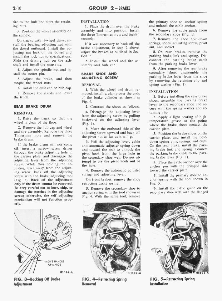
If the brake drum will not come off, insert a narrow screw driver through the brake adjusting hole in the carrier plate, and disengage the adjusting lever from the adjusting screw. While thus holding the adjusting lever away from the adjusting screw, back off the adjusting screw with the brake adjusting tool (Fig. 3). Back off the adjustment only if the drum cannot be removed. Be very careful not to burr, chip, or damage the notches in the adjusting screw; otherwise, the self adjusting mechanism will not function properly.
FIG. 3—Backing Off Brake Adjustment
INSTALLATION 1. Place the drum over the brake
assembly and into position. Install the three Tinnerman nuts and tighten securely.
If it was necessary to back off the brake adjustment, in step 2 above, adjust the brakes as outlined in Section 2.
2. Install the wheel and tire assembly and hub cap.
BRAKE SHOE AND ADJUSTING SCREW
REMOVAL 1. With the wheel and drum re
moved, install a clamp over the ends of the brake cylinder as shown in Fig. 4.
2. Contract the shoes as follows:
a. Disengage the adjusting lever from the adjusting screw by pulling backward on the adjusting lever (Fig. 1).
b. Move the outboard side of the adjusting screw upward and back off the pivot nut as far as it will go.
3. Pull the adjusting lever, cable and automatic adjuster spring down and toward the rear to unhook the pivot hook from the large hole in the secondary shoe web. D o not attempt to pry the pivot hook out of the hole.
4. Remove the automatic adjuster spring and adjusting lever.
O n front brakes, remove the shoe retracting assist spring.
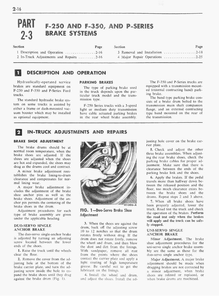
5. Remove the secondary shoe to anchor spring with the tool shown in Fig. 4. With the same tool, remove
FIG. 4—Retracting Spring Removal
the primary shoe to anchor spring and unhook the cable anchor.
6. Remove the cable guide from the secondary shoe (Fig. 1).
7. Remove the shoe hold-down springs, shoes, adjusting screw, pivot nut, and socket.
8. O n rear brakes, remove the parking brake link and spring. Disconnect the parking brake cable from the parking brake lever.
9. After removing the rear brake secondary shoe, disassemble the parking brake lever from the shoe by removing the retaining clip and spring washer (Fig. 1).
INSTALLATION 1. Before installing the rear brake
shoes, assemble the parking brake lever to the secondary shoe and secure with the spring washer and retaining clip.
2. Apply a light coating of high-temperature grease at the points where the brake shoes contact the carrier plate.
3. Position the brake shoes on the carrier plate, and install the hold-down spring pins, springs, and cups. O n the rear brake, install the parking brake link and spring. Connect the parking brake cable to the parking brake lever (Fig. 1).
4. Place the cable anchor over the anchor pin with the crimped side toward the carrier plate.
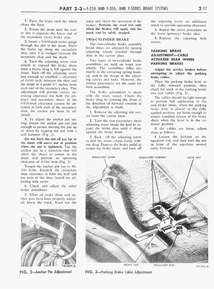
5. Install the primary shoe to anchor spring with the tool shown in Fig. 5.
6. Install the cable guide on the secondary shoe web with the flanged
FIG. 5—Retracting Spring Installation

P A R T 2-2-F- AND P-100 SERIES BRAKE SYSTEMS 2-11
hole fitted into the hole in the secondary shoe web. Thread the cable around the cable guide groove (Fig. 1).
It is imperative that the cable be positioned in this groove and not between the guide and the shoe web.
7. Install the secondary shoe to anchor (long) spring (Fig. 5).
Be certain that the cable end is not cocked or binding on the anchor pin when installed. All parts should be flat on the anchor pin. Remove the brake cylinder clamp.
O n front brakes, install the shoe retracting assist spring.
8. Apply high-temperature grease to the threads and the socket end of the adjusting screw. Turn the adjusting screw into the adjusting pivot nut to the limit of the threads and then back off Vi turn.
Interchanging the brake shoe adjusting screw assemblies from one side of the truck to the other would cause the brake shoes to retract rather than expand each time the automatic adjusting mechanism operated. T o prevent installation on the wrong side of the truck, the socket end of the adjusting screw is stamped with an R or L (Fig. 6). The adjusting pivot nuts can be distinguished by the number of lines machined around the body of the nut. T w o lines indicate a right hand nut; one line indicates a left hand nut.
9. Place the adjusting socket on the screw and install this assembly between the shoe ends with the adjusting screw nearest the secondary shoe.
10. Hook the cable hook into the hole in the adjusting lever from the backing plate side. The adjusting levers are stamped with an R or L to indicate their installation on a right or left hand brake assembly (Fig. 6).
>\ ADJUSTING SCREW
IDENTIFICATION LINES H1143-A
FIG. 6—Adjusting Screw and Lever Identification
11. Position the hooked end of the adjuster spring in the large hole in the primary shoe web, and connect the loop end of the spring to the adjuster lever hole.
12. Pull the adjuster lever, cable and automatic adjuster spring down and toward the rear to engage the pivot hook in the large hole in the secondary shoe web (Fig. 1).
13. After installation, check the action of the adjuster by pulling the section of the cable between the cable guide and the adjusting lever toward the secondary shoe web far enough to lift the lever past a tooth on the adjusting screw wheel. The lever should snap into position behind the next tooth, and release of the cable should cause the adjuster spring to return the lever to its original position. This return action of the lever will turn the adjusting screw one tooth.
If pulling the cable does not produce the action described, or if the lever action is sluggish instead of positive and sharp, check the position of the lever on the adjusting screw toothed wheel. With the brake in a vertical position (anchor at the top), the lever should contact the adjusting wheel one tooth above the center line of the adjusting screw. If the contact point is below this center line, the lever will not lock on the teeth in the adjusting screw wheel, and the screw will not be turned as the lever is actuated by the cable.
To determine the cause of this condition:
a. Check the cable end fittings. The cable should completely fill or extend slightly beyond the crimped section of the fittings. If it does not meet this specification, possible damage is indicated and the cable assembly should be replaced.
b. Check the cable length. The cable should measure \VA inches (plus or minus lki inch) from the far edge of the cable anchor hole to the inside edge of the cable hook.
c. Check the cable guide for damage. The cable groove should be parallel to the shoe web, and the body of the guide should lie flat against the web. Replace the guide if it shows damage.
d. Check the pivot hook on the lever. The hook surfaces should be square with the body of the lever for proper pivoting. Repair the hook or replace the lever if the hook shows damage.
e. See that the adjusting screw socket is properly seated in the notch in the shoe web.
BRAKE CARRIER PLATE— F-100 AND P-lOO SERIES TRUCKS EXCEPT 4-WHEEL DRIVE—FRONT
REMOVAL 1. Remove the wheel and brake
drum. Disconnect the brake line from the brake cylinder and submerge the end of the brake line in a can containing a small amount of brake fluid. This will minimize hydraulic line bleeding. Remove the brake shoes and the brake cylinder. O n the rear wheels, disconnect the parking brake lever from the cable.
2. If the rear carrier plate is being remolded, rotate the axle shaft so that the hole in the axle shaft flange aligns with the carrier plate retaining nuts, then remove the nuts. Pull the axle shaft assembly out of the housing with tool 4235-C, and a slide hammer tool T50T-100-C (Fig. 7). Lift off the carrier plate.
If the front carrier plate is being replaced, remove the bolts and nuts that secure the plate to the front wheel spindle and lift off the plate.
INSTALLATION 1. Position the rear carrier plate
on the retaining bolts in the axle housing flange. Insert the axle shaft assembly into the housing so that the splines engage the differential side gear, with the bearing retainer sliding onto the retaining bolts and against the carrier plate. Install the retaining nuts through the access hole in the axle shaft flange.
Position the front carrier plate on the wheel spindle and install the retaining bolts and nuts.
2. Install the brake cylinder and brake shoes. O n a rear brake, connect the parking brake cable to the lever.
3. Connect the brake line to the brake cylinder, then install the wheel and brake drum. Adjust the brake
FIG. 7—Axle Shaft Removal

2-12 G R O U P 2-BRAKES
AXLE SHAFT LOCK NUT
WHEEL HUB SPINDLE E1035-A
FIG. 8-Front Wheel Hub-4-Wheel Drive
shoes and bleed the hydraulic system.
BRAKE CARRIER PLATE-TRUCKS WITH 4-WHEEL DRIVE—FRONT
REMOVAL 1. Raise the truck on a hoist.
2. Remove the hub grease cap. Remove the hub retaining snap ring, and slide the splined driving hub from between the axle shaft and the wheel hub. Remove the driving hub spacer.
If the truck is equipped with a locking type hub, refer to Part 4-4.
3. Remove the lock nut, washer, and wheel bearing adjusting nut from the steering spindle. Remove the wheel, hub and drum as an assembly (Fig. 8). The wheel outer bearing will be forced off the spindle at the same time. Remove the wheel inner bearing cone.
4. Place a drain pan under the spindle arm assembly. Remove the oil baffle from the brake carrier plate.
5. Remove the cap screws which retain the brake carrier plate and spindle to the spindle arm. Remove the brake carrier plate and spindle (Fig. 9).
INSTALLATION 1. Position the spindle and the
brake carrier plate on the steering arm, and then install the retaining cap screws (Fig. 9). Install the oil baffle.
2. Install the wheel inner bearing cone on the spindle. Install the
STEERING DRAG BRAKE AXLE SPINDLE ARM LINK CARRIER PLATE SHAFT
ROD SPINDLE E1036-A
FIG. 9-Brake Carrier Plate Removal or Installation
wheel hub and drum. Install the driving hub spacer and then the wheel outer bearing cone and adjusting nut.
3. Rotate the wheel in both directions and at the same time tighten the bearing adjusting nut to bring the bearing rollers into proper contact. After the bearings are firmly seated, back off the adjusting nut '-'s turn (45°). Place the bearing adjusting lock washer on the spindle. Make sure the locking dowel on the adjusting nut enters the lock washer hole which most closely aligns with the dowel. Install the lock nut and torque to 40 ft-lbs (Fig. 8).
4. Install the driving hub and snap ring. Install the grease cap.
5. Fill the spindle arm with the proper grade and amount of lubricant.
MASTER CYLINDER
REMOVAL
O n a P-100 Series truck, turn the front wheels all the way to the left. and remove the fender apron attaching screws so that the apron can be moved to provide access to the master cylinder.
1. O n an F- or P-Series truck, disconnect the stoplight switch wires from the switch.
2. Disconnect the brake line from the brake tube fitting.
3. Force as much brake fluid as possible from the master cylinder into a suitable container by pushing down the brake pedal all the way several times.
4. Disconnect the rubber boot from the end of the master cylinder.
5. O n a F-100 Series truck, remove the bolts that hold the master cylinder against the dash panel, and lift the cylinder away from the push rod and out of the engine compartment.
O n a P-Series truck, remove the brake pedal return spring, remove the cotter pin from the clevis pin, and remove the master cylinder push rod and boot. Remove the three mounting bolts and remove the master cylinder from the mounting bracket and away from the truck.
INSTALLATION
1. O n an F-100 Series truck, with the rubber boot on the piston rod, guide the master cylinder over the end of the push rod, and position the cylinder against the mounting surface. Install the mounting bolts, and torque them to 12-18 ft-lbs.
O n a P-Series truck, assemble the master cylinder to the mounting bracket and secure with the three mounting bolts. Install the push rod and boot to the front of the master cylinder. Connect the front end of the push rod to the upper holes of the brake pedal extension with the clevis pin, and secure with a cotter pin.
2. O n an F- or P-Series truck, connect the brake line to the master cylinder fitting, but leave the brake line fitting loose.
3. Fill the master cylinder with heavy-duty brake fluid to the specified level.
4. Push the brake pedal down slowly by hand several times to let air escape at the brake line fitting. Hold the pedal down and tighten the brake line fitting. D o not release the brake pedal until the fitting is tightened, as additional air will be introduced into the master cylinder. Repeat this procedure until air ceases to escape at the fitting and a firm pedal is obtained.
5. After seeing that the master cylinder reservoir is filled with heavy-duty brake fluid to the specified level, install the filler cap. Wipe off the fluid from the outside of the cylinder and brake line.
6. Connect the stoplight switch wires to the switch.
7. Connect the rubber boot to the end of the cylinder. O n a P-100 Series truck, reposition the fender apron and secure with the five retaining bolts.

P A R T 2-2-F- AND P-100 SERIES BRAKE SYSTEMS 2-13
FIG. 10-F-100-250 Series Brake Pedal and Related Parts-Typical of P-100
PARKING BRAKE EQUALIZER TO CONTROL ASSEMBLY CABLE
REMOVAL
1. Raise the truck on a hoist. Push the equalizer lever slightly forward, and disconnect the cable rear (ball) end from the lever (Fig. 2).
2. Remove the parking brake cable retaining U-clip at the cross-member.
3. Lower the truck, open the hood, and remove the cable retaining clamp on the fender apron.
4. Remove the cable retaining U-clip at the handle assembly. Remove the cable from the truck.
INSTALLATION 1. Position the new cable through
the dash panel and connect it to the parking brake handle assembly. Secure the cable to the handle assembly with the U-clip.
2. Install the cable retaining clamp to the fender apron, and raise the truck on a hoist.
3. Route the cable through the crossmember and secure in place with the U-clip.
4. Push the equalizer lever forward and connect the cable rear (ball) end to the lever. Adjust the parking brake cable at the equalizer assembly.
PARKING BRAKE EQUALIZER TO REAR WHEEL CABLE
REMOVAL 1. Raise the truck and remove the
hub cap, wheel, and brake drum. Loosen the lock nut on the equalizer rod and disconnect the cable from the equalizer.
2. Remove the horseshoe-type clip that retains the cable housing to the frame bracket and pull the cable and housing out of the bracket.
3. Working on the wheel side (Fig. 1), compress the prongs on the cable retainer so that they can pass through the hole in the carrier plate. Draw the cable retainer out of the hole.
4. With the spring tension off the parking brake lever, lift the cable out of the slot in the lever, and remove the cable through the carrier plate hole.
INSTALLATION 1. Pull enough of the cable
through the housing so that the end
of the cable may be inserted over the slot in the parking brake lever. Pull the excess slack from the cable and insert the cable housing into the carrier plate access hole so that the retainer prongs expand (Fig. 1).
2. Thread the front end of the cable housing through the frame bracket and install the horseshoe-type retaining clip. Insert the ball end of the cable into the equalizer and tighten the lock nut on the equalizer slightly.
3. Install the rear brake drum, wheel, and hub cap, then adjust the rear brake shoes.
4. Tighten the lock nut on the equalizer rod until the slack is taken out of the cables.
5. Rotate both rear wheels to make sure that the parking brakes are not dragging.
BRAKE PEDAL—F-100—250, P-lOO SERIES TRUCK
REMOVAL
1. Remove the brake pedal retracting spring.
2. Remove the brake master cylinder push rod eccentric bolt nut, and remove the bolt and nylon bushing (Fig. 10).
3. Remove the retainer and spring washer from the pedal shaft. Then slide the shaft to the left and remove the brake pedal, bushings, and sleeve.
4. Remove the two bushings from the pedal, and remove the bumper from the pedal extension bracket.
INSTALLATION
1. Coat all bushings and the pedal shaft with a small quantity of Lubri-plate or an equivalent lubricant.
2. Install the bumper on the pedal extension bracket, and position the nylon bushings in the brake pedal shaft bore.
3. Position the brake pedal assembly and sleeve in the pedal support bracket. Slide the pedal shaft through the sleeve and pedal and secure with the spring washer and retainer.
4. Position the nylon bushing in the bore of the push rod. Connect the push rod to the brake pedal with the eccentric bolt and nut. Install the pedal retracting spring.
5. Adjust the brake pedal free travel to specifications by rotating the eccentric bolt. Hold the bolt securely and torque the lock nut to specifications. Recheck the pedal free travel to make sure that the adjustment did not change when the lock nut was tightened.
BRAKE PEDAL—P-350 THRU 5000 SERIES TRUCK
REMOVAL
1. Open the hood and disconnect the transmission gearshift rods from the shaft levers. Set the rods so that the maximum working space is obtained at the pedal support bracket.
2. Remove the pedal pads from the clutch and brake pedals (Fig. 11).

2-14 G R O U P 2-BRAKES
BRAKE PEDAL
PEDAL RETRACTING SPRINGS
PEDAL SHAFT
FIG. 11 -P-350 Series Brake Pedal and Related Parts
3. Remove the eight screws that re
tain the two floor covers at the steer
ing column, and remove the covers. Unlatch the engine cover assembly and open.
4. Remove the eight floor plate re
taining screws. Pull the accelerator pedal from the accelerator linkage and remove the floor plate.
5. Disconnect the clutch and
brake pedal retracting springs.
6. Loosen the pedal support bracket clamp bolt. Remove the cotter pins and clevis pins from the clutch and brake pedals.
7. Turn the front wheels full left. Through the left front fender apron, remove the locking pin from the clutch pedal and remove the pedal. Push the pedal shaft toward the cen-terline of the truck. From inside the cab, slide the pedal shaft and clutch
pedal lever to the right and out of the support bracket. Remove the brake pedal from the support bracket, then remove the bushings from
the pedal and the pedal support bracket.
INSTALLATION
1. Coat all bushings and the pedal shaft with a small quantity of Lu-
briplate or an equivalent lubricant. Install new bushings in the pedal
support bracket and the brake pedal.
2. Position the brake pedal in the support bracket, and slide the pedal
shaft and clutch pedal lever through the bracket and pedal.
3. Through the left front fender apron, install the clutch pedal on the shaft and secure it with a new locking pin.
4. Position the clutch rod on the clutch pedal lever, install the clevis pin and secure it with a new cotter pin.
5. Position the brake master cyl
inder push rod in the brake pedal, install the clevis pin and secure it with a new cotter pin.
6. Install the clutch and brake pedal retracting springs.
7. Adjust the brake pedal by removing the clevis pin from the master cylinder push rod and turning
the hex head of the push rod until
the specified free travel is obtained.
MAJOR REPAIR OPERATIONS
MASTER CYLINDER
DISASSEMBLY
1. Clean the outside of the cyl
inder and remove the filler cap and
gasket. Pour out any brake fluid
that may remain in the cylinder and
reservoir.
2. Remove the stoplight switch.
3. Remove the brake bolt, fitting,
and gaskets from the forward end of
the cylinder (Fig. 12 or 13). Remove
the snap ring from the bore at the
STOP LIGHT SWITCH
PUSH ROD
SNAP RING
FITTING SECONDARY
CUP
B O L T - ^ ^
FIG. 12—F-100 Brake Master Cylinder
PISTON
OUTLET CHECK VALVE
H1233-A

P A R T 2-2-F- AND P-100 SERIES BRAKE SYSTEMS 2-15
rear end of the cylinder and remove
the stop plate, piston, cup, spring,
check valve, and seat from the cyl
inder bore. If necessary, blow
through the forward bolt to remove
the parts.
ASSEMBLY
1. Dip all parts except the master
cylinder body in clean hydraulic
brake fluid. Use only heavy-duty
brake fluid.
2. Install the brake fitting, bolt,
and gaskets (Fig. 12 or 13), on the
forward end of the cylinder. Attach
the stoplight switch to the brake
bolt.
3. Install the valve seat, check
valve, spring, cup, piston, and stop
plate in the cylinder bore. Install the
snap ring in the rear end of the bore.
BRAKE BOLT FILLER CAP
STOPLIGHT SWITCH
MOUNTINGS-BOLT
PISTON RETURN / SNAP •I'-'f-li-:'": RING BOOT
STOP PLATE
BRAKE PEDAL ASSEMBLY
FIG. 13-P-100 Brake Master Cylinder
2-16
2-3 F-250 AND F-350, AND P-SERIES BRAKE SYSTEMS
Section Page
1 Description and Operation 2-16
2 In-Truck Adjustments and Repairs 2-16
Section
3 Removal and Installation 2-18
4 Major Repair Operations 2-25
DESCRIPTION AND OPERATION
Hydraulically-operated service brakes are standard equipment on
F-250 and F-350 and P-Series Ford trucks.
The standard hydraulic brake sys
tem on some trucks is assisted by
either a frame or dash-mounted vacuum booster which may be installed as optional equipment.
P A K K D N © S R ^ K E S
The type of parking brake used in the truck depends upon the particular truck model and the transmission type.
F-250 Series trucks with a 3-speed light or medium duty transmission have cable actuated parking brakes in the rear wheel brake assembly.
The F-350 and P-Series trucks are equipped with a transmission mounted (external contracting band) parking brake.
The band type parking brake consists of a brake drum bolted to the transmission main shaft companion flange, and an external contracting type band mounted on the rear of the transmission.
IN-TRUCK ADJUSTMENTS AND REPAIRS
BRAKE SHOE ADJUSTMENT
The brake drums should be at normal room temperature, when the brake shoes are adjusted. If the shoes are adjusted when the shoes are hot and expanded, the shoes may drag as the drums cool and contract.
A minor brake adjustment reestablishes the brake lining-to-drum clearance and compensates for normal lining wear.
A major brake adjustment includes the adjustment of the brake shoe anchor pins as well as the brake shoes. Adjustment of the anchor pin permits the centering of the brake shoes in the drum.
Adjustment procedures for each type of brake assembly are given under the applicable heading.
DUO-SERVO SINGLE ANCHOR BRAKE
The duo-servo single-anchor brake is adjusted by turning an adjusting screw located between the lower ends of the shoes.
1. Raise the truck until the wheels clear the floor.
2. Remove the cover from the adjusting hole at the bottom of the brake carrier plate, and turn the adjusting screw inside the hole to expand the brake shoes until they drag against the brake drum (Fig. 1).
3. When the shoes are against the drum, back off the adjusting screw 10 to 12 notches so that the drum rotates freely without drag. If the drum does not rotate freely, remove the wheel and drum, and then blow the dust and dirt from the linings. With sandpaper, remove all rust from the points where the shoes contact the carrier plate and apply a light coating of high temperature grease. Be careful not to get the lubricant on the linings.
4. Install the wheel and drum, and adjust the shoes. Install the ad
justing hole cover on the brake carrier plate.
5. Check and adjust the other three brake assemblies. W h e n adjusting the rear brake shoes, check the parking brake cables for proper adjustment. Make sure that there is clearance between the ends of the parking brake link and the shoes.
6. Apply the brakes. If the pedal travels more than halfway down between the released position and the floor, too much clearance exists between the brake shoes and the drums. Repeat steps 2 and 3 above.
7. When all brake shoes have been properly adjusted, lower the truck. Road test the truck and check the operation of the brakes. Perform the road test only when the brakes will apply and the truck can be safo-
UM-SERVO SINGLE ANCHOR BRAKE Minor Adjustment The brake
shoe adjustment procedures for the uni-servo single anchor brake assembly are the same as those for the duo-servo single anchor type.
Major Adjustment. A major brake adjustment should be made when dragging brakes are not corrected by a minor adjustment, when brake shoes are relined or replaced, or when brake drums are machined.
P A R T 2-3-F-250 AND F-350, AND P-SERIES BRAKE SYSTEMS 2-17
l. Raise the truck until the wheel clears the floor.
2. Rotate the drum until the feeler slot is opposite the lower end of the secondary (rear) brake shoe.
3. Insert a 0.010-inch feeler gauge through the slot in the drum. Move the feeler up along the secondary shoe until it is wedged between the secondary shoe and the drum.
4. Turn the adjusting screw (star wheel) to expand the brake shoes until a heavy drag is felt against the drum. Back off the adjusting screw just enough to establish a clearance of 0.010 inch, between the shoe and the drum at a point P/2 inches from each end of the secondary shoe. This adjustment will provide correct operating clearance for both the primary and secondary shoes. If the 0.010-inch clearance cannot be obtained at both ends of the secondary shoe, the anchor pin must be adjusted.
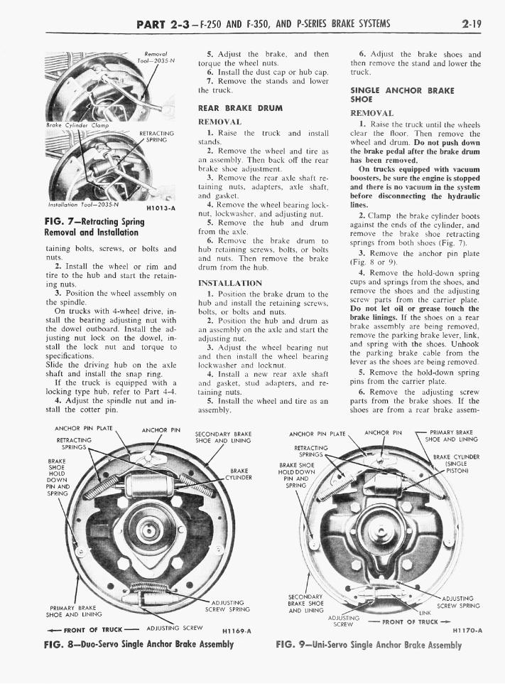
5. T o adjust the anchor pin setting, loosen the anchor pin nut just enough to permit moving the pin up or down by tapping the nut with a soft hammer (Fig. 2).
D o not back the nut off too far or the shoes will move out of position when the nut is tightened. Tap the anchor pin in a direction that will allow the shoes to center in the drum and provide an operating clearance of 0.010 inch (Fig. 2).
Torque the anchor pin nut to 80-100 ft-lbs. Recheck the secondary shoe clearance at both the heel and toe ends of the shoe. Install the adjusting hole cover.
6. Check and adjust the other brake assemblies.
7. W h e n all brake shoes and anchor pins have been properly adjusted, lower the truck. Road test the
truck and check the operation of the brakes. Perform the road test only when the brakes will apply and the truck can be safely stopped.
TWO-CYLINDER BRAKE The two-cylinder brake assembly
brake shoes are adjusted by turning adjusting wheels reached through slots in the carrier plate.
T w o types of two-cylinder brake assemblies are used on truck rear wheels. The assemblies differ primarily in the retracting spring hookup, and in the design of the adjusting screws and locks. However, the service procedures are the same for both assemblies.
The brake adjustment is made with the truck raised. Check the brake drag by rotating the drum in the direction of forward rotation as the adjustment is made.
1. Remove the adjusting slot covers from the carrier plate.
2. Turn the rear (secondary shoe) adjusting screw inside the hole to expand the brake shoe until it drags against the brake drum.
3. Back off the adjusting screw so that the drum rotates freely without drag. Depress the brake pedal to center the brake shoes, and back off
the adjusting screw an additional notch to provide operating clearance.
4. Repeat the above procedure on the front (primary) brake shoe.
5. Replace the adjusting hole covers.
PARKING BRAKE ADJUSTMENT—CABLE ACTUATED REAR WHEEL PARKING BRAKES
Adjust the service braJkes before attempting to adjust the parking brake cables.
Place the parking brake lever in the fully released position, then check for slack in the parking brake two rear cables (Fig. 3).
The cables should be tight enough to provide full application of the rear brake shoes, when the parking brake lever is placed in the fully applied position, yet loose enough to ensure complete release of the brake shoes when the lever is in the released position.
If the cables are loose, adjust them as follows:
1. Loosen the locknut on the equalizer rod, and then turn the nut in front of the equalizer several turns forward.
EQUALIZER LEVER EQUALIZER ASSEMBLY LOCK NUT
H1007-A FRONT NUT EQUALIZER ROD HI173-A
FSG. 2—Anchor Pin Adjustment FIG. 3—Parking Brake Cable Adjustment

2-18 G R O U P 2-BRAKES
ANCHOR ADJUSTING SCREW C A M
BAND^ * N " h. LINK
ADJUSTING ROD
ADJUSTING NUT ADJUSTING BRACKET FOR UPPER PART NUT LOWER RETAINING OF BRAKE BAND PART OF SCREWS
BRAKEBAND H1183-A
FIG. 4—Typical Band Type Parking Brake
2. Turn the locknut forward against the equalizer until the cables are just tight enough to remove the slack. Excessive tightening may pull the brake shoes off their anchors.
3. W h e n the cables are properly adjusted, tighten both nuts against the equalizer.
PARKING BRAKE ADJUSTMENT—BAND-TYPE PARKING BRAKES
1. On cable-controlled parking brakes (Fig. 4), move the parking brake lever to the fully released position. O n a truck with a rod-type linkage, set the lever at the first notch.
2. Check the position of the cam to make sure the flat portion is resting on the brake band bracket. If the cam is not flat with the bracket, remove the clevis pin from the upper part of the cam, and adjust the clevis rod to allow the flat portion of the cam to rest on the brake band
f I
2%
:i6 GAUGE SHEET STEEL
.."")
-*—0 700-0 710 ** ! V
•
IK*'
FIG. 5—Push Rod Gauge Dimensions
bracket. Install the clevis pin and cotter pin (Fig. 4).
3. Remove the lock wire from the anchor adjusting screw, and turn the adjusting screw clockwise until a clearance of 0.010-inch is established between the brake lining and the brake drum at the anchor bracket. Install the lock wire in the anchor adjusting screw.
4. Loosen the lock nut on the adjusting screw for the lower half of the brake band, and adjust the screw to establish a 0.010-inch clearance between the lining and the brake drum at the lower half of the brake band (Fig. 4). Tighten the lock nut.
5. Turn the upper band adjusting rod nut until a 0.010-inch clearance
Push Rod Gauge
H1277-B
FIG. 6-Push Rod Adjustment
is established between the upper half of the band and the drum.
DASH-MOUNTED BOOSTER PUSH ROD ADJUSTMENT
The push rod is provided with an adjustment screw to maintain the correct relationship between the booster control valve plunger and the master cylinder piston. Failure to maintain this relationship will prevent the master cylinder from completely releasing hydraulic pressure and can cause the brakes to drag. Remove the master cylinder for access to the booster push rod.
To check the adjustment of the screw, fabricate a gauge of the dimensions shown in Fig. 5. Then place the gauge against the master cylinder mounting surface of the booster body as shown in Fig. 6. The push rod screw should be adjusted so that the end of the screw just touches the inner edge of the slot in the gauge.
REMOVAL AND INSTALLATION
FRONT BRAKE DRUM REMOVAL
1. Raise the truck and install stands.
2. Back off the brake shoe adjustment. Remove the hub cap and/or dust cap.
3. Remove the spindle nut cotter pin, spindle nut, and washer.
O n trucks with 4-wheel drive, re
move the snap ring from the end of the axle shaft. Slide the driving hub off the shaft. Remove the lock nut using tool T59T-1197-AA, the nut lock, and the bearing adjusting nut.
If the truck is equipped with a locking type hub refer to Part 4-4.
4. Remove the wheel assembly.
5. Remove the front wheel to hub retaining nuts or rim and tire retain
ing nuts. Remove the wheel or rim and tire from the hub and drum.
6. Remove the brake drum retainers and retaining bolts, screws, or bolts and nuts.
7. Remove the brake drum from the hub.
INSTALLATION 1. Place the brake drum to the
hub and install the retainers and re-
P A R T 2 - 3 - F-250 AND F-350, AND P-SERIES BRAKE SYSTEMS 2-19
Installation Too/-2035-N
FIG. 7—Retracting Spring Removal and Installation
taining bolts, screws, or bolts and nuts.
2. Install the wheel or rim and tire to the hub and start the retaining nuts.
3. Position the wheel assembly on the spindle.
O n trucks with 4-wheel drive, install the bearing adjusting nut with the dowel outboard. Install the adjusting nut lock on the dowel, install the lock nut and torque to specifications. Slide the driving hub on the axle shaft and install the snap ring.
If the truck is equipped with a locking type hub, refer to Part 4-4.
4. Adjust the spindle nut and install the cotter pin.
5. Adjust the brake, and then torque the wheel nuts.
6. Install the dust cap or hub cap. 7. Remove the stands and lower
the truck.
REAR BRAKE DRUM
REMOVAL 1. Raise the truck and install
stands. 2. Remove the wheel and tire as
an assembly. Then back off the rear brake shoe adjustment.
3. Remove the rear axle shaft retaining nuts, adapters, axle shaft, and gasket.
4. Remove the wheel bearing lock-nut, lockwasher, and adjusting nut.
5. Remove the hub and drum from the axle.
6. Remove the brake drum to hub retaining screws, bolts, or bolts and nuts. Then remove the brake drum from the hub.
INSTALLATION
1. Position the brake drum to the hub and install the retaining screws, bolts, or bolts and nuts.
2. Position the hub and drum as an assembly on the axle and start the adjusting nut.
3. Adjust the wheel bearing nut and then install the wheel bearing lockwasher and locknut.
4. Install a new rear axle shaft and gasket, stud adapters, and retaining nuts.
5. Install the wheel and tire as an assembly.
6. Adjust the brake shoes and then remove the stand and lower the truck.
SINGLE ANCHOR BRAKE SHOE
REMOVAL 1. Raise the truck until the wheels
clear the floor. Then remove the wheel and drum. D o not push down the brake pedal after (he brake drum has been removed.
O n trucks equipped with vacuum boosters, be sure the engine is stopped and there is no vacuum in the system before disconnecting the hydraulic lines.
2. Clamp the brake cylinder boots against the ends of the cylinder, and remove the brake shoe retracting springs from both shoes (Fig. 7).
3. Remove the anchor pin plate (Fig. 8 or 9).
4. Remove the hold-down spring cups and springs from the shoes, and remove the shoes and the adjusting screw parts from the carrier plate. D o not let oil or grease touch the brake linings. If the shoes on a rear brake assembly are being removed, remove the parking brake lever, link, and spring with the shoes. Unhook the parking brake cable from the lever as the shoes are being removed.
5. Remove the hold-down spring pins from the carrier plate.
6. Remove the adjusting screw parts from the brake shoes. If the shoes are from a rear brake assem-
ANCHOR PIN PLATE
RETRACTING SPRINGS
ANCHOR PIN SECONDARY BRAKE SHOE AND LINING
PRIMARY BRAKE SHOE AND LINING
—— FRONT OF TRUCK •
ADJUSTING SCREW SPRING
ANCHOR PIN PLATE
RETRACTING SPRINGS
BRAKE SHOE HOLD D O W N PIN AND SPRING /
ANCHOR PIN PRIMARY BRAKE SHOE AND LINING
BRAKE CYLINDER (SINGLE PISTON)
ADJUSTING SCREW
ADJUSTING
SCREW SPRING LINK
FRONT OF TRUCK •
HI 169-A H1170-A
FIG. 8—Duo-Servo Single Anchor Brake Assembly FIG. 9—Uni-Servo Single Anchor Brake Assembly

2-20 G R O U P 2-BRAKES
BRAKE CYLINDER COVER
BRAKE SHOE
GUIDE BOLT NUT AND
COTTER PIN
RETRACTING SPRING
ANCHOR PIN 1
ADJUSTING SCREW AND WHEEL ASSEMBLY
BRAKE SHOE
ANCHOR PIN SUPPORT
bly, remove the parking brake lever from the secondary shoe.
INSTALLATION
1. Coat all points of contact between the brake shoes and the other brake assembly parts with Lubriplate or a similar lubricant. Lubricate the adjusting screw threads.
2. Place the adjusting screw, socket, and nut on the brake shoes so that the star wheel on the screw is opposite the adjusting hole in the carrier plate. Then install the adjusting screw spring.
3. Position the brake shoes and the adjusting screw parts on the carrier plate, and install the hold-down spring pins, springs, and cups. When assembling a rear brake, connect the parking brake lever to the secondary shoe, and install the link and spring with the shoes (Fig. 13). Be sure to hook the parking brake cable to the lever.
4. Install the anchor pin plate on the pin.
5. Install the brake shoe retracting springs on both shoes (Fig. 7), being careful not to bend the hooks or to stretch the springs beyond the attaching points. The primary shoe spring must be installed first.
6. Remove the clamp from the brake cylinder boots.
7. Install the wheel and drum.
8. Bleed the system and adjust the brakes. Check the brake pedal operation after bleeding the system. Then lower the truck.
TWO-CYLINDER BRAKE SHOE
REMOVAL 1. Raise the truck until the wheels
clear the floor. Remove the wheel, and then remove the drum or the hub and drum assembly. Mark the hub and drum to aid assembly in the same position.
O n trucks equipped with vacuum or air boosters, be sure the engine is stopped and there is no vacuum or air pressure in the system before disconnecting the hydraulic lines.
2. Clamp the brake cylinder boots against the ends of the cylinder and remove the four brake shoe retracting springs with the tool shown in Fig. 7.
3. Remove the brake shoe guide bolt cotter pin, nut, washer, and bolt from both shoes, and remove the shoes from the carrier plate (Fig. 10).
FIG. 10—Two Cylinder Brake
4. Remove the clamp-type adjusting wheel lock from the anchor pin support, and unthread the adjusting screw and wheel assembly from the anchor pin support.
INSTALLATION
1. Clean the carrier plate ledges with sandpaper. Coat all points of contact between the brake shoes and other brake assembly parts with high temperature grease.
2. Thread the adjusting screw and wheel assembly into the anchor pin support and install the clamp-type adjusting wheel lock. Thread the adjusting wheel into the support so that the brake shoe will rest against the adjusting wheel end.
3. Place the brake shoe over the two brake shoe anchor pins, insert the ends in the brake cylinder links, and install the shoe guide bolt, washer, and nut (Fig. 10). Finger tighten the nut, then back off one full turn, and install the cotter pin.
4. Install the four retracting springs with the tool shown in Fig. 7.
5. Remove the cylinder clamps, install the drum or the hub and drum assembly, then install the wheel assembly. Align the marks on the hub and drum during installation.
6. Bleed the brake system and adjust the brakes. Lower the truck.
B R A K E CARRIER P L A T E —
F-250 AND 350 AND P-SERIES TRUCKS EXCEPT F-250 TRUCKS WITH 4-WHEEL DRIVE—FRONT
REMOVAL
1. Remove the wheel and tire.
2. On front wheels, remove the grease cap, wheel bearing adjusting nut, washer and outer bearing, then remove the hub and drum assembly from the spindle.
O n rear wheels, remove the rear axle shaft flange retaining nuts and axle shaft. Remove the rear wheel bearing lock nut, lock washer, and adjusting nut, then remove the hub and drum assembly from the axle housing.
3. Remove the brake shoes and adjusting screw from the carrier plate (See "Single Anchor Brake Shoe"). Disconnect the brake line from the brake cylinder and submerge the end of the brake line in a can containing a small amount of brake fluid. This will minimize hydraulic line bleeding.
4. Remove the carrier plate retaining bolts and nuts, then remove the carrier plate from the front wheel spindle or rear axle housing.
5. Remove the retaining bolts and lock washers, and the brake cylinder from the carrier plate.
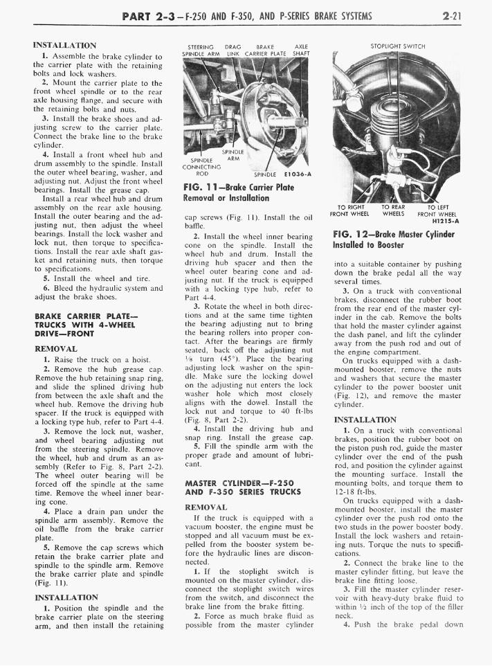
P A R T 2-3-F-250 AND F-350, AND P-SERIES BRAKE SYSTEMS 2-21
INSTALLATION 1. Assemble the brake cylinder to
the carrier plate with the retaining bolts and lock washers.
2. Mount the carrier plate to the front wheel spindle or to the rear axle housing flange, and secure with the retaining bolts and nuts.
3. Install the brake shoes and adjusting screw to the carrier plate. Connect the brake line to the brake cylinder.
4. Install a front wheel hub and drum assembly to the spindle. Install the outer wheel bearing, washer, and adjusting nut. Adjust the front wheel bearings. Install the grease cap.
Install a rear wheel hub and drum assembly on the rear axle housing. Install the outer bearing and the adjusting nut, then adjust the wheel bearings. Install the lock washer and lock nut, then torque to specifications. Install the rear axle shaft gasket and retaining nuts, then torque to specifications.
5. Install the wheel and tire. 6. Bleed the hydraulic system and
adjust the brake shoes.
BRAKE CARRIER PLATE-TRUCKS WITH 4-WHEEL DRIVE—FRONT
REMOVAL 1. Raise the truck on a hoist.
2. Remove the hub grease cap. Remove the hub retaining snap ring, and slide the splined driving hub from between the axle shaft and the wheel hub. Remove the driving hub spacer. If the truck is equipped with a locking type hub, refer to Part 4-4.
3. Remove the lock nut, washer, and wheel bearing adjusting nut from the steering spindle. Remove the wheel, hub and drum as an assembly (Refer to Fig. 8, Part 2-2). The wheel outer bearing will be forced off the spindle at the same time. Remove the wheel inner bearing cone.
4. Place a drain pan under the spindle arm assembly. Remove the oil baffle from the brake carrier plate.
5. Remove the cap screws which retain the brake carrier plate and spindle to the spindle arm. Remove the brake carrier plate and spindle (Fig. 11).
INSTALLATION 1. Position the spindle and the
brake carrier plate on the steering arm, and then install the retaining
STEERING DRAG BRAKE AXLE SPINDLE ARM LINK CARRIER PLATE SHAFT
ROD SPINDLE E1036-A
FIG. 1 1 -Brake Carrier Plate Removal or Installation
cap screws (Fig. 11). Install the oil baffle.
2. Install the wheel inner bearing cone on the spindle. Install the wheel hub and drum. Install the driving hub spacer and then the wheel outer bearing cone and adjusting nut. If the truck is equipped with a locking type hub, refer to Part 4-4.
3. Rotate the wheel in both directions and at the same time tighten the bearing adjusting nut to bring the bearing rollers into proper contact. After the bearings are firmly seated, back off the adjusting nut Va turn (45°). Place the bearing adjusting lock washer on the spindle. Make sure the locking dowel on the adjusting nut enters the lock washer hole which most closely aligns with the dowel. Install the lock nut and torque to 40 ft-lbs (Fig. 8, Part 2-2).
4. Install the driving hub and snap ring. Install the grease cap.
5. Fill the spindle arm with the proper grade and amount of lubricant.
MASTER CYLINDER—F-250 AND F-350 SERIES TRUCKS
REMOVAL If the truck is equipped with a
vacuum booster, the engine must be stopped and all vacuum must be expelled from the booster system before the hydraulic lines are disconnected.
I. If the stoplight switch is mounted on the master cylinder, disconnect the stoplight switch wires from the switch, and disconnect the brake line from the brake fitting.
2. Force as much brake fluid as possible from the master cylinder
STOPLIGHT SWITCH
TO RIGHT TO REAR TO LEFT FRONT WHEEL WHEELS FRONT WHEEL
H1215-A
FIG. 1 2—Brake Master Cylinder Installed to Booster
into a suitable container by pushing down the brake pedal all the way several times.
3. O n a truck with conventional brakes, disconnect the rubber boot from the rear end of the master cylinder in the cab. Remove the bolts that hold the master cylinder against the dash panel, and lift the cylinder away from the push rod and out of the engine compartment.
O n trucks equipped with a dash-mounted booster, remove the nuts and washers that secure the master cylinder to the power booster unit (Fig. 12), and remove the master cylinder.
INSTALLATION 1. O n a truck with conventional
brakes, position the rubber boot on the piston push rod, guide the master cylinder over the end of the push rod, and position the cylinder against the mounting surface. Install the mounting bolts, and torque them to 12-18 ft-lbs. O n trucks equipped with a dash-
mounted booster, install the master cylinder over the push rod onto the two studs in the power booster body. Install the lock washers and retaining nuts. Torque the nuts to specifications.
2. Connect the brake line to the master cylinder fitting, but leave the brake line fitting loose.
3. Fill the master cylinder reservoir with heavy-duty brake fluid to within Vi inch of the top of the filler neck.
4. Push the brake pedal down

2-22 G R O U P 2-BRAKES
slowly by hand several times to let air escape at the brake line fitting. Hold the pedal down and tighten the brake line fitting. Release the brake pedal. D o not release the brake pedal until the fitting is tightened as additional air will be introduced into the master cylinder.
O n trucks equipped with dash-mounted booster, the cylinder can be bled at the bleed screw on the cylinder.
5. After seeing that the master cylinder reservoir is filled with heavy-duty brake fluid to within % inch of the top of the filler neck, install the outside of the cylinder and brake line.
6. If the stoplight switch is mounted on the master cylinder, connect the stoplight switch wires to the switch.
7. O n a truck with conventional brakes, connect the rubber boot to the end of the cylinder.
8. Check, and if necessary, adjust the brake pedal free-travel.
MASTER CYLINDER—P-SERIES TRUCKS
REMOVAL 1. If the truck is equipped with
a vacuum booster, the engine must be stopped and all vacuum must be expelled from the booster system before the hydraulic lines are disconnected.
2. Turn the front wheels all the way to the left, and remove the fender apron attaching screws so that the apron can be moved to provide access to the master cylinder.
3. Disconnect the stoplight switch wires from the switch.
4. Disconnect the brake line from the brake tube fitting.
5. Force as much brake fluid as possible from the master cylinder into a suitable container by pushing down the brake pedal all the way several times.
6. Disconnect the rubber boot from the end of the master cylinder.
7. Remove the brake pedal return spring, remove the cotter pin from the clevis pin, and remove the master cylinder push rod and boot. Remove the three mounting bolts and remove the master cylinder from the mounting bracket and away from the truck.
INSTALLATION 1. Assemble the master cylinder
to the mounting bracket and secure
with the three mounting bolts. Install the push rod and boot to the front of the master cylinder. Connect the front end of the push rod to the upper holes of the brake pedal extension with the clevis pin, and secure with a cotter pin. O n a truck equipped with a vacuum booster, connect the push rod and insert the clevis pin at the lower holes of the pedal extension. Install the brake pedal retracting spring.
2. Connect the brake line to the master cylinder fitting, but leave the brake line fitting loose.
3. Fill the master cylinder with heavy-duty brake fluid to the specified level.
4. Push the brake pedal down slowly by hand several times to let air escape at the brake line fitting. Hold the pedal down and tighten the brake line fitting. D o not release the brake pedal until the fitting is tightened, as additional air will be introduced into the master cylinder. Repeat this procedure until air ceases to escape at the fitting and a firm pedal is obtained.
5. After seeing that the master cylinder reservoir is filled with heavy-duty brake fluid to the specified level, install the filler cap. Wipe off the fluid from the outside of the cylinder and brake line.
6. Connect the stoplight switch wires to the switch.
7. Connect the rubber boot to the end of the cylinder. Reposition the fender apron and secure with the five retaining bolts.
8. Check and, if necessary, adjust the brake pedal free travel.
VACUUM BOOSTERS—FRAME-MOUNTED PISTON TYPE
REMOVAL 1. Depress the brake pedal sev
eral times to remove all vacuum from the system.
2. Loosen the booster air inlet tube clamp, and remove the tube. Disconnect the hydraulic lines and the vacuum hose at the booster.
3. Remove the booster mounting bolts, then remove the booster. D o not remove the breather or the vacu u m check valve unless operating conditions indicate repairs are necessary.
INSTALLATION I, Position the booster on the
mounting bracket, and install the
mounting bolts, using new lock-washers.
2. Connect the hydraulic lines to the booster. Tighten connections securely.
3. Connect the air intake hose to the control valve air inlet tube. Tighten the hose clamp securely. If necessary, clean the air inlet element.
4. Bleed the brake system as outlined under "Hydraulic System Bleeding," Part 2-1.
5. Connect the vacuum tube to booster hose to the booster. Tighten the hose clamps securely.
6. Perform the checks and tests as outlined in Part 2-1.
VACUUM BOOSTERS—DASH-MOUNTED-DIAPHRAGM TYPE
REMOVAL 1. Support the master cylinder
with a prop from the underside.
2. Remove the master cylinder-to-booster retaining nuts.
3. Remove the clip that retains the master cylinder outlet line to the bracket on the dash panel.
4. Loosen the clamp that secures the manifold vacuum hose to the booster and remove the hose. Remove the reservoir hose from the booster unit, if so equipped.
5. Pull the master cylinder off the booster, and leave it supported by the prop far enough away to allow removal of the booster assembly.
6. From inside the cab, remove the eccentric bolt and lock nut that secure the booster valve operating rod to the brake pedal. Remove the nuts that retain the booster mounting bracket to the dash panel.
7. Remove the booster assembly from the engine compartment.
INSTALLATION 1. Mount the booster and bracket
assembly to the engine side of the dash panel, by sliding the bracket mounting studs and the valve operating rod in through the holes in the dash panel.
2. From inside the cab, install the booster mounting bracket - to - dash panel retaining nuts.
3. Position the master cylinder to the booster assembly, install the retaining nuts, and remove the prop.
4. Position the master cylinder outlet line to the bracket on the dash panel, and install the retaining clip.

P A R T 2-3-F-250 AND F-350, AND P-SERIES BRAKE SYSTEMS 2-23
5. Connect the manifold vacuum hose to the booster and secure with the clamp. Connect the reservoir hose to the booster, if so equipped.
6. From inside the cab, connect the booster valve operating rod to the brake pedal with the eccentric bolt and lock nut. Adjust the brake pedal free-travel.
7. Start the engine and check the operation of the brake system.
PARKING BRAKE EQUALIZER TO CONTROL ASSEMBLY CABLE
This procedure applies only to trucks equipped with cable actuated parking brakes.
REMOVAL 1. Raise the truck on a hoist.
Push the equalizer lever slightly forward, and disconnect the cable rear (ball) end from the lever (Fig. 3).
2. Remove the parking brake cable retaining U-clip at the cross-member.
3. Lower the truck, open the hood, and remove the cable retaining clamp on the fender apron.
4. Remove the cable retaining U-clip at the handle assembly. Remove the cable from the truck.
INSTALLATION 1. Position the new cable through
the dash panel and connect it to the parking brake handle assembly. Secure the cable to the handle assembly with the U-clip.
2. Install the cable retaining clamp to the fender apron, and raise the truck on a hoist.
3. Route the cable through the crossmember and secure in place with the U-clip.
4. Push the equalizer lever forward and connect the cable rear (ball) end to the lever. Adjust the parking brake cable at the equalizer assembly.
PARKING BRAKE EQUALIZER TO REAR WHEEL CABLE
This procedure applies only to trucks equipped with cable actuated parking brakes.
REMOVAL 1. Raise the truck and remove the
hub cap, wheel, and brake drum. Loosen the lock nut on the equalizer rod and disconnect the cable from the equalizer.
PARKING BRAKE LINK SPRING
. REAR BRAKE ASSEMBLY
PARKING LEVER PIVOT POINT
PARKING BRAKE LINK
-4-FRONT OF TRUCK-
PARKING RAKE CABLE
FIG. 1 3—Parking Brake Assembly
2. Remove the horseshoe - type clip that retains the cable housing to the frame bracket and pull the cable and housing out of the bracket.
3. Working on the wheel side (Fig.13), compress the prongs on the cable retainer so that they can pass through the hole in the carrier plate. Draw the cable retainer out of the hole.
4. With the spring tension off the parking brake lever, lift the cable out of the slot in the lever, and remove the cable through the carrier plate hole.
INSTALLATION
1. Pull enough of the cable through the housing so that the end of the cable may be inserted over the slot in the parking brake lever. Pull the excess slack from the cable and insert the cable housing into the carrier plate access hole so that the retainer prongs expand (Fig. 13).
2. Thread the front end of the cable housing through the frame bracket and install the horseshoe-type retaining clip. Insert the ball end of the cable into the equalizer and tighten the lock nut on the equalizer slightly.
3. Install the rear brake drum.
wheel, and hub cap, then adjust the rear brake shoes.
4. Tighten the lock nut on the equalizer rod until the slack is taken out of the cables.
5. Rotate both rear wheels to make sure that the parking brakes are not dragging.
BAND AND DRUM—(BAND TYPE PARKING BRAKE)
This procedure applies to F-350 series trucks, and P-Series trucks that are equipped with a 3-speed H. D. transmission.
REMOVAL 1. Shift the transmission into low
gear and disconnect the drive shaft companion flange from the transmission output shaft flange by removing the four nuts (Fig. 4).
2. Apply the parking brake, remove the transmission output shaft flange retaining nut, then release the parking brake.
3. Remove the cotter pin and clevis pin, and disconnect the adjusting rod from the cam.
4. Remove the cotter pin and clevis pin, and remove the cam link from the cam.

2-24 G R O U P 2-BRAKES
FIG. 14-F-250 and F-350 Series Brake Pedal and Related Parts
5. Remove the lock wire and the anchor adjusting screw.
6. Remove the brake band adjusting bolts and nuts.
7. Remove the brake bracket retaining cap screws.
8. Lift the brake band and lining assembly off the drum.
9. Inspect the brake lining, and replace it if the distance between the brake lining surface and the top of the rivet is less than V32 inch.
W h e n relining a parking brake band, follow the procedure used in Part 2-1.
10. Inspect the drum braking surface. If the drum is rough or scored, it should be replaced. Remove the drum and output shaft flange as an assembly.
INSTALLATION 1. Position the parking brake
drum and output shaft flange assembly to the transmission output shaft, and install the retaining nut.
2. Position the parking brake band assembly over the drum, and install the bracket retaining screws.
3. Install the brake band adjusting bolts and nuts and springs.
4. Connect the cam link to the lower end of the cam with clevis and cotter pin.
5. Connect the adjusting rod to the upper end of the cam with clevis and cotter pin.
6. Adjust the parking brake, and install a lock wire in the anchor adjusting screw.
7. Apply the parking brake, torque the transmission output shaft flange nut to specifications, then release the parking brake.
8. With the transmission in low gear, connect the drive shaft at the flange and torque the four retaining nuts.
BRAKE PEDAL—F-250 AND F-350 SERIES TRUCKS
REMOVAL 1. Remove the brake pedal re
tracting spring.
2. Remove the brake master cylinder push rod eccentric bolt nut, and remove the bolt and nylon bushing (Fig. 14).
3. Remove the retainer and spring washer from the pedal shaft. Then
slide the shaft to the left and remove the brake pedal, bushings, and sleeve.
4. Remove the two bushings from the pedal, and remove the bumper from the pedal extension bracket.
INSTALLATION 1. Coat all bushings and the pedal
shaft with a small quantity of Lu-briplate or an equivalent lubricant.
2. Install the bumper on the pedal extension bracket, and position the nylon bushings in the brake pedal shaft bore.
3. Position the brake pedal assembly and sleeve in the pedal support bracket. Slide the pedal shaft through the sleeve and pedal and secure with the spring washer and retainer.
4. Position the nylon bushing in the bore of the push rod. Connect the push rod to the brake pedal with the eccentric bolt and nut. Install the pedal retracting spring.
5. Adjust the brake pedal free travel to specifications by rotating the eccentric bolt. Hold the bolt securely and torque the lock nut to specifications. Recheck the pedal free travel to make sure that the adjustment did not change when the lock nut was tightened.
BRAKE PEDAL—P-SERIES TRUCKS
REMOVAL
1. Open the hood and disconnect the transmission gearshift
rods from the shaft levers. Set the rods so that the maximum working space is obtained at the pedal support bracket.
2. Remove the pedal pads from the clutch and brake pedal (Fig. 15).
3. Remove the eight screws that retain the two floor covers at the steering column, and remove the covers. Unlatch the engine cover assembly and open.
4. Remove the eight floor plate retaining screws. Pull the accelerator pedal from the accelerator linkage and remove the floor plate.
5. Disconnect the clutch and brake pedal retracting springs.
6. Loosen the pedal support bracket clamp bolt. Remove the cotter pins and clevis pins from the clutch and brake pedals.
7. Turn the front wheels full left. Through the left front fender apron, remove the locking pin from the clutch pedal and remove the pedal. Push the pedal shaft toward the centerline of the truck. From inside the cab, slide the pedal shaft and clutch pedal lever to the right and out of the support bracket. Remove the brake pedal from the support bracket, then remove the bushings from the pedal and the pedal support bracket.
INSTALLATION
1. Coat all bushings and the pedal shaft with a small quantity of Lubriplate or an equivalent lubricant. Install new bushings

P A R T 2-3-F-250 AND F-350, AND P-SERIES BRAKE SYSTEMS 2-25
in the pedal support bracket and the brake pedal.
2. Position the brake pedal in the support bracket, and slide the pedal shaft and clutch pedal lever through the bracket and pedal.
3. Through the left front fender apron, install the clutch pedal on the shaft and secure it with a new locking pin.
4. Position the clutch rod on the clutch pedal lever, install the clevis pin and secure it with a new cotter pin.
5. Position the brake master cylinder push rod in the brake pedal, install the clevis pin and secure it with a new cotter pin.
6. Install the clutch and brake pedal retracting springs.
7. Adjust the brake pedal by removing the clevis pin from the master cylinder push rod and turning the hex head of the push rod until the specified free travel is obtained.
BRAKE PEDAL
PEDAL RETRACTING SPRINGS
SUPPORT BRACKET
PEDAL SHAFT
FIG. 1 5-P-350 Series Brake Pedal and Related Parts
H1035-A
MAJOR REPAIR OPERATIONS
MASTER CYLINDER—F- A N D P-SERIES TRUCKS-EXCEPT F-350 TRUCKS EQUIPPED WITH A DASH-MOUNTED BOOSTER
DISASSEMBLY
1. Clean the outside of the cylinder and remove the filler cap and gasket. Pour out any brake fluid that may remain in the cylinder and reservoir.
2. Remove the stoplight switch if it is mounted on the master cylinder.
3. Remove the brake bolt, fitting, and gaskets from the forward end of the cylinder (Fig. 16 or 17). Remove the snap ring from the bore at the rear end of the cylinder and remove the stop plate, piston, cup, spring, check valve, and seat from the cylinder bore. If necessary, blow through the forward bolt hole to remove the parts.
ASSEMBLY
1. Dip all parts except the master cylinder body in clean hydraulic brake fluid. Use only heavy-duty-brake fluid.
2. Install the brake fitting, bolt, and gaskets (Fig. 16 or 17). on the
PUSH ROD
SNAP RING
PISTON
H1233-A
FIG. 16—Typical Brake Master Cylinder F-250 Trucks
forward end of the cylinder. If the stoplight switch mounts on the master cylinder, attach the switch
to the brake bolt. 3. Install the valve seat, check
valve, spring, cup, piston, and stop plate in the cylinder bore. Install the snap ring in the rear end of the bore.
MASTER CYLINDER—F-350 TRUCK WITH DASH-MOUNTED BOOSTER
DISASSEMBLY 1. Clean the outside of the master
cylinder, loosen the retaining bolt, and remove the filler cap, filter and gasket assembly (Fig. 18). Pour out any brake fluid remaining in the cylinder or reservoir.
2. Remove ihe remaining snap ring and slide the return spring off the master cylinder push rod.
3. Remove the end cap. check valve and spring, and piston stop from the front end of the master cylinder bore. Remove the O-ring from the end cap.
4. Remove the bushing snap ring
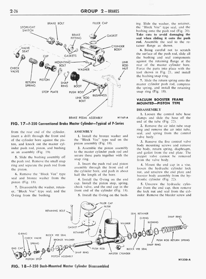
2-26 G R O U P 2-BRAKES
BRAKE BOLT FILLER CAP
STOPLIGHT SWITCH
RETURN SPRING
BRAKE PEDAL ASSEMBLY H1167-A
FIG. 17—F-350 Conventional Brake Master Cylinder—Typical of P-Series
from the rear end of the cylinder,
insert a drift through the front end of the cylinder bore against the pis
ton, and knock out the master cylinder push rod, piston, and bushing
as an assembly (Fig. 19).
5. Slide the bushing assembly off
the push rod. Remove the small snap ring and separate the push rod from
the piston.
6. Remove the "Block Vee" type
seal and bronze washer from the
piston (Fig. 18).
7. Disassemble the washer, retain
er, "Block Vee" type seal, and the O-ring from the bushing.
ASSEMBLY 1. Install the bronze washer and
the "Block Vee" type seal on the piston assembly (Fig. 18).
2. Assemble the piston assembly to the master cylinder push rod and secure these parts together with the snap ring.
3. Insert the push rod and piston assembly through the front end of the cylinder bore, and push in about half the length of the bore.
4. Install the O-ring on the end cap. Install the piston stop, spring, check valve, and the end cap in the front end of the cylinder (Fig. 18).
5. Install the O-ring on the bush
ing. Slide the washer, the retainer, the "Block Vee" type seal, and the bushing onto the push rod (Fig. 20). Take care to avoid damaging the seal when sliding it onto the push rod. Assemble the seal to the retainer flange as shown.
6. Being careful not to scratch the surface of the push rod, slide all the bushing and seal components against the retaining flange at the rear of the master cylinder bore. Force the parts into place with the tool shown in Fig. 21, and install the bushing snap ring.
7. Slide the return spring onto the master cylinder push rod, compress the spring, and install the retaining snap ring (Fig. 18).
VACUUM BOOSTER FRAME MOUNTED—PISTON TYPE
DISASSEMBLY
1. Loosen the control tube hose clamps and slide the hose off the end of the tube (Fig. 22).
2. Remove the air inlet tube snap ring and remove the air inlet tube, seal, and spring from the control valve body.
3. Remove the five control valve body mounting screws and remove the body, return spring, diaphragm, and gasket from the end plate. The poppet valve cannot be removed from the valve body.
4. Mount the end cap in a vise, loosen the hydraulic cylinder lock nut, and unscrew the end plate and booster body assembly from the hydraulic cylinder (Fig. 22).
5. Unscrew the hydraulic cylinder from the end cap, then remove the lock nut and seal from the cylinder. Remove the bleeder screw and
RETAINING BOLT
:ILLER CAP
FILTER
O-RING
1 CHECK VALVE
BLOCK VEE SEAL
BRONZE WASHER
SEAL RETAINER
O-RING
BUSHING
SNAP RING
PUSH ROD RETURN SPRING
SNAP RING
BLOCK VEE SEAL
SNAP RING MASTER CYLINDER PISTON ASSEMBLY
PISTON STOP H1320-A
FIG. 1 8—F-350 Dash-Mounted Master Cylinder Disassembled

PART 2-3 • F-250 AND F-350, AND P-SERIES BRAKE SYSTEMS 2-27
FIG. 1 9-Master Cylinder Push Rod, Piston, and Bushing Removal
copper gasket from the end cap then remove the end cap from the vise.
6. Scribe a line across the booster body and end plate so that these parts can be reassembled in their original position. Remove the four hook bolts, and slide the booster body from the vacuum piston assembly.
7. Compress the vacuum piston return spring by pressing down on the end plate and using hook-type clamps similar to those in Fig. 23. Hold the spring compressed.
8. Remove the hydraulic piston from the push rod by sliding the retainer spring (on the hydraulic piston) back, and removing the retainer
pin. 9. Remove the hook clamps and
separate the vacuum piston and push rod assembly, and the return spring from the end plate.
10. Clamp one of the bolt flanges of the end plate in a vise. Unscrew the control valve cylinder from the end plate, then remove the rubber gasket from the cylinder. Remove
WASHER
BUSHING
BLOCK VEE SEAL H1270-A
FIG. 20—Assembly of Seal and Bushing Components to Master Cylinder
Push Rod
Tool-T61B-3576-A-
H1271-A
FIG. 21-Master Cylinder Bushing Installation
the snap ring and stop washer, then press the control valve piston assembly from the cylinder (Fig. 22). The piston should come out of the front end of the cylinder to avoid damage to the cups.
11. Remove the small retainer, then remove the piston cups and spacer from the control valve piston.
12. Remove the hydraulic cylinder end seal from the end plate (Fig. 22). Remove the snap ring, then remove the push rod seal cup parts (retainer washer, spring spacer, seal retainer, seal cup and stop washer) from the end plate.
13. Remove the end plate from the vise and place it on two wooden blocks with the hydraulic cylinder side up. Drive the push rod leather seal assembly out of the end plate, using a flat end rod or drift.
14. Clamp the vacuum piston and push rod assembly in a vise at the hexagonal nut. Remove the vacuum piston retaining nut and disassemble the vacuum piston from the push rod (Fig. 22). Remove the flat
washer.
ASSEMBLY
1. Install the bleeder screw and a new copper gasket in the end cap, and place the end cap in a vise. Thread the hydraulic cylinder into the end cap with the milled flats on the cylinder next to the end cap

2-28 G R O U P 2-BRAKES
RUBBER GASKET CONTROL VALVE CYLINDER STOP WASHER
GASKET
DIAPHRAGM
CONTROL VALVE PISTON
- PISTON CUPS
CONTROL TUBE
CONTROL VALVE BODY
SPRING
SEAL
AIR INLET TUBE AND COVER
SNAP RING -%V-5\
BLEEDER SCREW
PUSH ROD LEATHER SEAL
BOOSTER BODY SEAL
HOOK BOLT
BOOSTER PISTON
FIG. 22—Frame-Mounted Booster—Exploded View
(Fig. 22). Place a wrench on the milled flats and tighten the cylinder securely.
2. Thread the lock nut on the hydraulic cylinder to the limit of the threads. Position a new lock nut seal between the two sections of thread on the hydraulic cylinder.
3. Place the end plate on two wooden blocks with the hydraulic cylinder side of the end plate up. Press the push rod leather seal into the end plate with the lip of the leather seal toward the hydraulic cylinder side of the end plate.
4. Dip the control valve piston seals in heavy duty brake fluid, assemble the seals on the piston with the spacer between the two seals, and secure with the C-type retainer (Fig. 22). The lip of each piston should point toward the retainer end of the piston. Insert the piston assembly into the control valve cylinder from the rear side of the cylinder. Install the stop washer at the
front end of the cylinder against the piston, and secure in place with the snap ring.
5. Clamp the end plate in a vise at one of the bolt flanges. Place a new rubber gasket over the threaded end of the control valve cylinder. thread the cylinder into the end plate, and tighten securely with a l'/s-inch socket.
6. T o assemble the push rod seal cup parts (Fig. 22), insert the push rod through the leather seal at the rear side of the end plate. The rod will hold the parts in alignment as they are installed. Install the stop washer with the chamfered side toward the end plate, the seal cup with the lip of the cup away from the stop washer, the seal retainer with the flanged end next to the cup, and the spacer with the chamfered end next to the cup. Install the spring over the seal retainer and against the flat side of the spacer. Place the retainer washer against the spring.
and compress the spring until the washer is to the inner side of the snap ring groove. Install the snap ring in the groove, then remove the push rod. Install a new cylinder end seal.
7. Fabricate a vacuum piston assembly ring by cutting a 1-inch section from an old cylinder shell of correct size. Place the assembly ring (Fig. 24) on the bench and assemble the vacuum piston parts in the assembly ring, installing the larger diameter piston plate with the chamfered side of the hole up, the leather piston packing with the lip of the packing up, the seal ring, and the small diameter piston plate with the chamfered side of the hole down.
8. Cut the wicking to the required length, and assemble it against the inner face of the piston packing lip.
9. Position the expander ring inside the wicking, with the gripper points up and the notch at the loop end of the expander ring under the
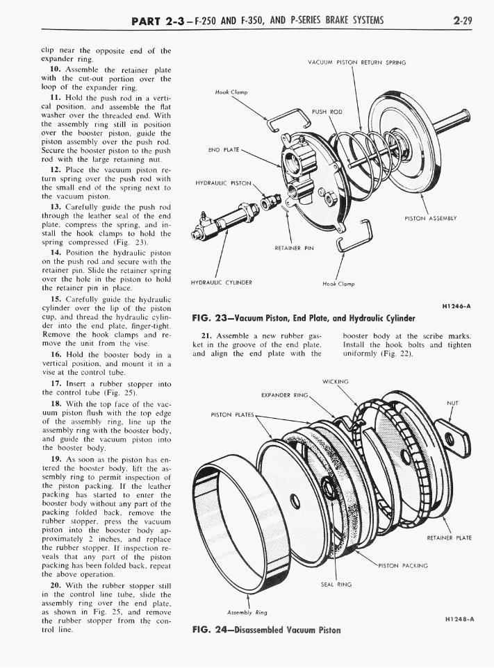
P A R T 2-3-F-250 AND F-350, AND P-SERIES BRAKE SYSTEMS 2-29
VACUUM PISTON RETURN SPRING
HYDRAULIC CYLINDER Hook Chmp
H1246-A
FIG. 23—Vacuum Piston, End Plate, and Hydraulic Cylinder
clip near the opposite end of the expander ring.
10. Assemble the retainer plate with the cut-out portion over the loop of the expander ring.
11. Hold the push rod in a vertical position, and assemble the flat washer over the threaded end. With the assembly ring still in position over the booster piston, guide the piston assembly over the push rod. Secure the booster piston to the push rod with the large retaining nut.
12. Place the vacuum piston return spring over the push rod with the small end of the spring next to the vacuum piston.
13. Carefully guide the push rod through the leather seal of the end plate, compress the spring, and install the hook clamps to hold the spring compressed (Fig. 23).
14. Position the hydraulic piston on the push rod and secure with the retainer pin. Slide the retainer spring over the hole in the piston to hold the retainer pin in place.
15. Carefully guide the hydraulic cylinder over the lip of the piston cup, and thread the hydraulic cylinder into the end plate, finger-tight. Remove the hook clamps and remove the unit from the vise.
16. Hold the booster body in a vertical position, and mount it in a vise at the control tube.
17. Insert a rubber stopper into the control tube (Fig. 25).
18. With the top face of the vacu u m piston flush with the top edge of the assembly ring, line up the assembly ring with the booster body, and guide the vacuum piston into the booster body.
19. As soon as the piston has entered the booster body, lift the assembly ring to permit inspection of the piston packing. If the leather packing has started to enter the booster body without any part of the packing folded back, remove the rubber stopper, press the vacuum piston into the booster body approximately 2 inches, and replace the rubber stopper. If inspection reveals that any part of the piston packing has been folded back, repeat the above operation.
20. With the rubber stopper still in the control line tube, slide the assembly ring over the end plate, as shown in Fig. 25, and remove the rubber stopper from the control line.
21. Assemble a new rubber gasket in the groove of the end plate, and align the end plate with the
booster body at the scribe marks. Install the hook bolts and tighten uniformly (Fig. 22).
Assembly Ring
H1248-A
FIG. 24—Disassembled Vacuum Piston

2-30 G R O U P 2-BRAKES
Assembly Ring Rubber Sloppe
HOOK BOLT' H1247-A
FIG. 25—Assembly Ring Removal
22. Drop the two hose clamps over the integral control tube on the booster body and assemble the hose on the control tube. If the control valve body is being replaced, transfer the removable control tube from the old to the new body.
23. The use of guide pins, threaded into the end plate, will simplify the assembly of the control valve body and components to the end
plate, and will reduce the possibility of damaging the diaphragm during assembly. Guide pins may be made by cutting the heads from five 32 x 2Vi-inch machine screws.
Install the guide pins, position a new gasket and the diaphragm over the pins, then position the return spring in the recess in the diaphragm (Fig. 22).
24. Assemble the control valve
body over the pins so that the control tube on the valve body enters the hose on the booster body tube. Hold the control valve body and parts against the end plate, and remove one guide pin at a time, replacing it with a screw and lock washer. Tighten the screws securely.
25. Secure the hose clamps in position.
26. Install the spring, the seal, and the air inlet tube and cover assembly to the control valve body and secure in place with the snap ring (Fig. 22).
27. Align the bleeder screw in the end cap with the bleeder screw in the end plate by manually turning the hydraulic cylinder in the end plate threads. While holding the hydraulic cylinder in this properly aligned position, securely tighten the cylinder lock nut (Fig. 22).
VACUUM BOOSTER DASH-MOUNTED—DIAPHRAGM TYPE
DISASSEMBLY 1. Remove the air filter cover, air
filter, and retainer assembly from the booster body (Fig. 26).
2. Remove the vacuum manifold and check valve assembly, and the
RETAINER
VACUUM MANIFOLD AND CHECK VALVE ASSEMBLY BOOSTER BODY (TRUCKS WITH VACUUM RESERVOIR) GROMMET
RETAINER MJ/
SUPPORT RINGS CLAMP BAND
DIAPHRAGM RETURN SPRING
X
BELLOWS PROTECTOR
DIAPHRAGM ASSEMBLY
P * W VACUUM MANIFOLD AND ' - CHECK VALVE ASSEMBLY
TRUCKS WITHOUT VACUUM RESERVOIR O-RING Ilk
HUB-TO-DIAPHRAGMI ""
CONTROL VALVE PLUNGER ASSEMBLY
SEAL AND / r\^" ADAPTER ASSEMBLY jLjr\ft( \
BLOCK VEE
PLUNGER GUIDES
REACTION LEVER RING V RETAINER (
RETA'\ k rVf A4 REACTION CONE _ \ I \ I V I \ \
BOOSTER PUSH ROD / rfjN,
CUSHION RING f
REACTION LEVERS
O-RING ADAPTER-TO-END PLATE)
ROD PLASTIC RETAINER
BOOT .
ATMOSPHERIC VALVE
RETURN SPRING
REACTION LOAD RING
RUBBER REACTION RING
VALVE OPERATING ROD
C-RING
MOUNTING BRACKET
BOOSTER END PLATE H1321-A
FIG. 26—Dash-Mounted Booster Disassembled

P A R T 2-3-F-250 AND F-350, AND P-SERIES BRAKE SYSTEMS 2-31
REACTION
PLUNGE
DIAPHRAGM ASSEMBLY
RUBBER REACTION RING
REACTION CONE
PUSH ROD ASSEMBLY \
\ REACTION LEVER
RING ASSEMBLY
FIG. 29—Disassembly or Assembly—Reaction Components, and Push Rod-to-Valve Hub
H1267-A
BOOSTER BODY
FIG. 27-Bellows-to-Booster Body Engagement
rubber grommet from the booster body.
3. Remove the rubber boot from the mounting bracket and valve operating rod.
4. Remove the retaining nuts, and disassemble the mounting bracket from the booster end plate. Remove the gasket from the end plate.
5. Remove the large C-nng that retains the rear seal adapter assembly to the booster end plate (Fig. 26).
6. Disengage the bellows from the booster body by pushing the bellows into the vacuum chamber (Fig. 27).
7. Scribe a line across the booster body and end plate to facilitate proper alignment at assembly. Remove the bolt and nut from the clamp band, remove the clamp band, and separate the end plate from the booster body. Remove (he diaphragm return spring.
8. Separate the bellows, control valve, and diaphragm assembly from the end plate. Remove the O-ring that fits between the hub rear seal
FIG. 28—Bellows Removal or Installation
adapter assembly and the end plate (Fig. 26).
9. Remove the large bellows retainer ring and the bellows assembly from the diaphragm and valve assembly (Fig. 28).
10. Remove the retainer, support rings, bellows stay, and protector from the bellows (Fig. 26).
11. Remove the booster push rod assembly, the reaction lever and ring assembly, and the rubber reaction ring from the control valve hub (Fig. 29). Remove the two plastic plunger guides from the control valve plunger.
12. Remove the retainer, the
cushion ring, and the reaction cone
from the booster push rod, then disassemble the levers from the reaction ring (Figs. 26 and 29).
13. Remove the hub rear seal and adapter assembly from the rear of the control valve hub, then separate the hub and plunger assembly from the diaphragm. Remove the retainer, the reaction load ring, the return spring, and the atmospheric valve from the hub and plunger, then slide the plunger out of the hub (Fig. 30). Remove the O-ring from the front side of the diaphragm. Remove the hub rear seal from the adapter assembly.
HUB REAR SEAL AND ADAPTER ASSEMBLY
DIAPHRAGM
O-RING IHUB-TO-DIAPHRAGMI
REACTION LOAD RING
W '/ RETAINER
RETURN SPRING
CONTROL VALVE HUB
CONTROL VALVE PLUNGER
H1268A
FIG. 30—Disassembly or Assembly—Control Valve Components-to-Hub and Diaphragm

2-32 G R O U P 2-BRAKES
FIG. 31—Valve Operating Rod and Plunger Assembly
14. Remove the O-rings and the "Block Vee" type seal from the valve plunger (Fig. 31).
15. D o not remove the valve operating rod from the control valve plunger unless the plunger assembly or the rod is to be replaced. To remove, hold the rod firmly and force the plunger off the rod, breaking the plastic retainer. Remove all the broken pieces of the plastic retainer from the groove in the plunger, if the plunger is to be used again with a replacement rod.
ASSEMBLY
1. If the valve operating rod was removed from the plunger, assemble a new plastic retainer to the end of the rod (Fig. 26). Insert the rod into the plunger so that the retainer engages the groove in the plunger.
2. Install the "Block Vee" type seal and the O-rings on the valve plunger assembly (Fig. 31).
3. Insert the control valve plunger into the control valve hub from the rear of the hub (Fig. 30).
4. Assemble the atmospheric valve, the return spring and the reaction load ring to the valve plunger and hub.
5. Push the control valve plunger assembly forward and the reaction load ring backward against the return spring in order to install the retainer in the groove of the plunger.
6. Install the O-ring in the groove at the front side of the diaphragm. Assemble the valve plunger and hub assembly to the diaphragm so that the opening rod and the small-diameter end of the hub enter the front side of the diaphragm and protrude from the rear side.
7. Install the "Block Vee" type seal in the hub rear seal adapter, with the sealing lip toward the rear. Slide the seal and adapter assembly over the rear end of the valve hub so that the large-diameter side of the adapter bears against the diaphragm.
8. Install the two plastic plunger
guides in their grooves on the valve plunger assembly (Fig. 29).
9. Install the rubber reaction ring in the valve hub so that the ring locating knob indexes in the notch in the hub. with the ring tips toward the front (Fig. 29).
10. Assemble the reaction lever and ring assembly, then install the assembly in the valve hub (Fig. 29).
11. Assemble the reaction cone and cushion ring to the push rod, and secure to the rod with the retainer (Fig. 26). Install the push rod assembly to the valve hub so that the valve plunger indexes in the push rod (Fig. 29).
12. Assemble the bellows retainer to the rear fold of the bellows. Install the bellows stay and the two support rings. The plastic stay is located in the center fold of the bellows with a support ring in the fold at each side of the stay (Fig. 26). Assemble the bellows protector to the front fold.
13. Position the bellows assembly over the push rod against the front side of the diaphragm. Secure the bellows to the diaphragm by installing the retainer ring (Fig. 28). Make sure that the retainer ring is fully seated.
14. Install the O-ring in the groove at the front side of the end plate. Assemble the bellows, control valve, and diaphragm assembly to the end plate by inserting the valve hub through the front side of the end plate with the small diameter side of the seal adapter protruding from the rear side of the end plate (Fig. 26).
15. Install the large C-ring to the rear seal adapter at the rear side of the end plate.
16. Install the diaphragm return spring in the booster body, and assemble the end plate to the booster body so that the marks scribed during disassembly are in alignment. Be sure that the lip of the diaphragm is evenly positioned between the retaining flanges of the booster body and
end plate. Secure the booster body, diaphragm, and end plate together with the clamp band, and tighten the clamp bolt and nut.
17. Pull the front lip of the bellows through the booster body and position it around the outer face of the booster body (Fig. 27)
18. Place the gasket on the end plate, slide the mounting bracket over the end plate studs, and install the retaining nuts (Fig. 26).
19. Slide the rubber boot over the valve operating rod and engage the boot with the groove on the mounting bracket.
20. Install the rubber grommet in the vacuum port in the booster body. The large diameter side of the grommet should be to the outside of the booster. Force the vacuum manifold and check valve assembly through the grommet. D o not push the grommet into the vacuum chamber.
21. Install the air filter cover, filter, and retainer assembly to the booster body.
22. Check the booster push rod adjustment as described on Page 2-18.
VACUUM BOOSTER FRAME-MOUNTED—DIAPHRAGM TYPE
The Midland Hy-Power diaphragm type booster used on P-500 -5000 trucks is an 81s inch unit (Fig. 32).
REMOVAL 1. With the engine stopped, de
press the brake pedal several times to remove all vacuum from the booster system.
2. Disconnect the 2 hydraulic lines and vacuum hose from the booster.
3. O n a frame-mounted booster, loosen the air breather hose clamp and disconnect the hose from the booster, remove the 3 mounting bolts and lockwashers and remove the booster.
O n a frame-mounted booster, do not remove the breather or the vacuum check valve unless operating conditions indicate repairs are necessary.
DISASSEMBLY
1. Remove the by-pass tube from both the control valve body and the rear body (Fig. 32).
2. Mark both halves of the diaphragm body with a scriber. Mark the flanges of the control valve body and the slave cylinder body so the
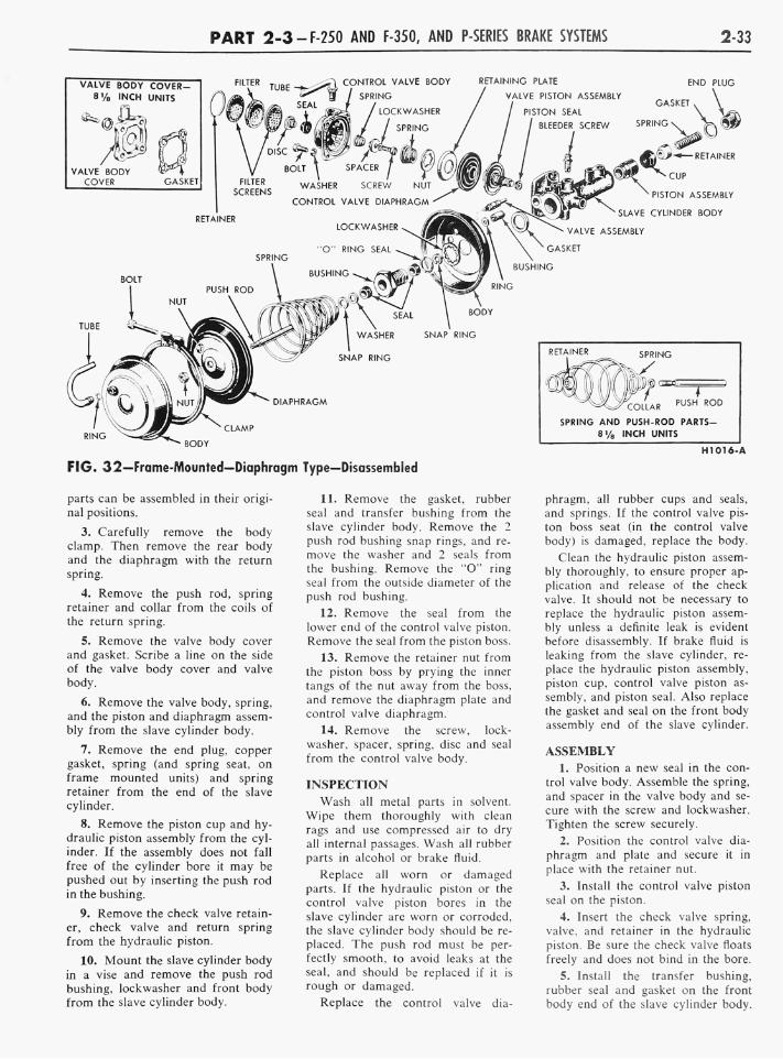
P A R T 2-3-F-250 AND F-350, AND P-SERIES BRAKE SYSTEMS 2-33
VALVE BODY COVER-8'A INCH UNITS
Mo VALVE BODY W^\
COVER GASKET
CONTROL VALVE BODY RETAINING PLATE END PLUG
GASKET ,
• BODY
PUSH ROD COLLAR
SPRING AND PUSH-ROD PARTS-8 % INCH UNITS
FIG. 32—Frame-Mounted—Diaphragm Type—Disassembled
parts can be assembled in their original positions.
3. Carefully remove the body clamp. Then remove the rear body and the diaphragm with the return spring.
4. Remove the push rod, spring retainer and collar from the coils of the return spring.
5. Remove the valve body cover and gasket. Scribe a line on the side of the valve body cover and valve body.
6. Remove the valve body, spring, and the piston and diaphragm assembly from the slave cylinder body.
7. Remove the end plug, copper gasket, spring (and spring seat, on frame mounted units) and spring retainer from the end of the slave cylinder.
8. Remove the piston cup and hydraulic piston assembly from the cylinder. If the assembly does not fall free of the cylinder bore it may be pushed out by inserting the push rod in the bushing.
9. Remove the check valve retainer, check valve and return spring from the hydraulic piston.
10. Mount the slave cylinder body in a vise and remove the push rod bushing, lockwasher and front body from the slave cylinder body.
11. Remove the gasket, rubber seal and transfer bushing from the slave cylinder body. Remove the 2 push rod bushing snap rings, and remove the washer and 2 seals from the bushing. Remove the "O" ring seal from the outside diameter of the push rod bushing.
12. Remove the seal from the lower end of the control valve piston. Remove the seal from the piston boss.
13. Remove the retainer nut from the piston boss by prying the inner tangs of the nut away from the boss, and remove the diaphragm plate and control valve diaphragm.
14. Remove the screw, lockwasher, spacer, spring, disc and seal from the control valve body.
INSPECTION Wash all metal parts in solvent.
Wipe them thoroughly with clean rags and use compressed air to dry all internal passages. Wash all rubber parts in alcohol or brake fluid.
Replace all worn or damaged parts. If the hydraulic piston or the control valve piston bores in the slave cylinder are worn or corroded, the slave cylinder body should be replaced. The push rod must be perfectly smooth, to avoid leaks at the seal, and should be replaced if it is rough or damaged.
Replace the control valve dia
phragm, all rubber cups and seals, and springs. If the control valve piston boss seat (in the control valve body) is damaged, replace the body.
Clean the hydraulic piston assembly thoroughly, to ensure proper application and release of the check valve. It should not be necessary to replace the hydraulic piston assembly unless a definite leak is evident before disassembly. If brake fluid is leaking from the slave cylinder, replace the hydraulic piston assembly, piston cup, control valve piston assembly, and piston seal. Also replace the gasket and seal on the front body assembly end of the slave cylinder.
ASSEMBLY 1. Position a new seal in the con
trol valve body. Assemble the spring, and spacer in the valve body and secure with the screw and lockwasher. Tighten the screw securely.
2. Position the control valve diaphragm and plate and secure it in place with the retainer nut.
3. Install the control valve piston seal on the piston.
4. Insert the check valve spring, valve, and retainer in the hydraulic piston. Be sure the check valve floats freely and does not bind in the bore.
5. Install the transfer bushing, rubber seal and gasket on the front body end of the slave cylinder body.

2-34 G R O U P 2-BRAKES
6. Install the push rod seals, washer and snap rings in the push rod bushing. Both push rod seals should be installed with the open end of the seal facing the slave cylinder body. Install the lockwasher over the end of the bushing. Install the bushing seal.
7. Mount the slave cylinder body in a vise. Position the front body over the end of the slave cylinder, inserting the transfer bushing with proper hole in the front body.
8. Thread the push rod bushing in place. Be sure the front body seats squarely on the slave cylinder body, and tighten the bushing securely.
9. Coat the piston bores in the slace cylinder body with heavy-duty brake fluid. Dip the hydraulic cylinder piston, seals, spring retainer, and spring in the brake fluid.
10. Install the hydraulic piston in the slave cylinder bore with the recessed end (or the large bore of the piston) toward the push rod bushing. Carefully position the piston cup with the recessed end toward the large spring, spring retainer and spring on top of the piston.
O n a frame-mounted booster, install the spring seat in the spring coils.
11. Position a new copper gasket on the end plug and screw the plug
in the slave cylinder. Tighten the end plug securely.
12. Dip the control valve piston and diaphragm in the heavy duty brake fluid. Position the control valve spring on the diaphragm with the small end of the spring over the piston boss.
13. Position the control valve body over the spring, align the scribe marks, install the valve body on the slave cylinder body and secure with 4 attaching bolts and lockwashers. Tighten the bolts securely.
14. Position a new gasket on the control valve body, position the valve body cover over the gasket and secure the cover with 4 bolts and lock-washers. Tighten the bolts securely.
15. Position the collar over the threaded end of the push rod. Position the spring retainer in the spring as shown in the insert in Fig. 32. Insert the push rod and collar in the coils of the spring and through the retainer. Position the diaphragm over the threaded end of the push rod and secure it with the push rod nut. Tighten the nut securely. After the nut is tightened coat the threads of the push rod with shellac to prevent leakage. Coat the push rod with heavy-duty type brake fluid.
16. Place the return spring over the push rod bushing.
17. Place the rear body on top of the diaphragm with the scriber mark on the rear body in alignment with that on the front body. Compress the return spring, and install and tighten the clamp, making certain the diaphragm bead is properly positioned between the 2 halves of the body.
18. Install the by-pass tube.
INSTALLATION 1. Position the brake booster on
the mounting bracket, and install the mounting bolts, using new lock-washers.
2. Connect the hydraulic lines to the booster. Tighten connections securely.
3. O n a frame-mounted booster, attach the air intake hose to the control valve air inlet fitting, and tighten the clamp securely. If necessary, clean the air inlet element.
4. Bleed the brake system as outlined under "Hydraulic System Bleeding," (Part 2-1).
5. Connect the vacuum hose to the vacuum check valve (or tube) on the booster. Tighten the clamps securely.
6. Perform the checks and tests as outlined on Part 2-1.
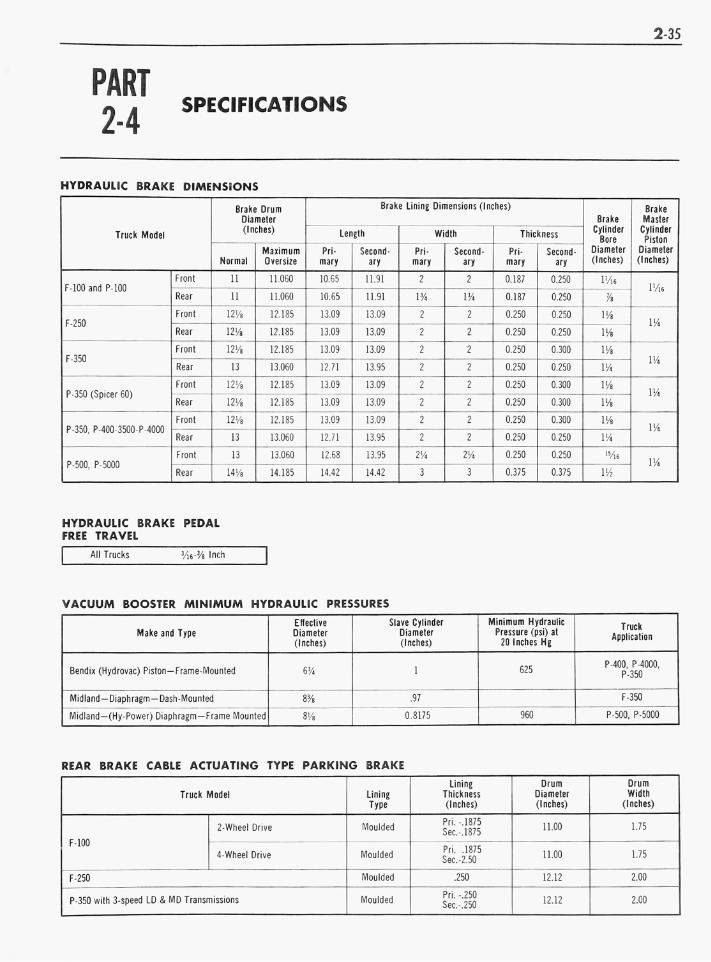
2-35
PART 2-4
SPECIFICATIONS
HYDRAULIC BRAKE DIMENSIONS
Truck Model
F-100 and P-100
F-250
F-350
P-350 (Spicer 60)
P-350, P-400-3500 P 4000
P-500, P-5000
Front
Rear
Front
Rear
Front
Rear
Front
Rear
Front
Rear
Front
Rear
Brake Drum Diameter (Inches)
Normal
11
11
12V&
12Va
12H
13
1214
12M
12H
13
13
WA
Maximum Oversize
11.060
11.060
12.185
12.185
12.185
13.060
12.185
12.185
12.185
13.060
13.060
14.185
Brake Lining Dimensions (Inches)
Length
Primary
10.65
10.65
13.09
13.09
13.09
12.71
13.09
13.09
13.09
12.71
12.68
14.42
Secondary
11.91
11.91
13.09
13.09
13.09
13.95
13.09
13.09
13.09
13.95
13.95
14.42
Width
Primary
2
VA
2
2
2
2
2
2
2
2
2V,
3
Secondary
2
VA
2
2
2
2
2
2
2
2
VA
3
Thickness
Primary
0.187
0.187
0.250
0.250
0.250
0.250
0.250
0.250
0.250
0.250
0.250
0.375
Secondary
0.250
0.250
0.250
0.250
0.300
0.250
0.300
0.300
0.300
0.250
0.250
0.375
Brake Cylinder Bore
Diameter (Inches)
l'/l6
'A
VA
VA
VA
VA
VA
VA
VA
VA 1S/l6
Wi
Brake Master Cylinder Piston
Diameter (Inches)
l'/l6
VA
VA
VA
VA
VA
HYDRAULIC BRAKE PEDAL FREE TRAVEL
All Trucks 3/i6-3/8 Inch
VACUUM BOOSTER MINIMUM HYDRAULIC PRESSURES
Make and Type
Bendix (Hydrovac) Piston—Frame-Mounted
Midland —Diaphragm—Dash-Mounted
Midland—(Hy-Power) Diaphragm —Frame Mounted
Effective Diameter (Inches)
6%
m 8'/8
Slave Cylinder Diameter (Inches)
1
.97
0.8175
Minimum Hydraulic Pressure (psi) at 20 Inches Hg
625
960
Truck Application
P-400, P-4000, P-350
F-350
P-500, P-5000
REAR BRAKE CABLE ACTUATING TYPE PARKING BRAKE
Truck Model
F-100
2-Wheel Drive
4-Wheel Drive
F-250
P-350 with 3-speed LD & M D Transmissions
Lining Type
Moulded
Moulded
Moulded
Moulded
Lining Thickness (Inches)
Pri.-.1875 Sec-,1875
Pri. .1875 Sec-2.50
.250
Pri. -.250 Sec.250
Drum Diameter (Inches)
11.00
11.00
12.12
12.12
Drum Width
(Inches)
1.75
1.75
2.00
2.00

2-36 G R O U P 2-BRAKES
EXTERNAL CONTRACTING BAND TYPE PARKING BRAKE
Truck Model
F-350
P-350, P-400, P-500, P-4000, P-5000
Lining Type
Woven
Moulded
Lining Thickness (Inches) .156
.250
No. ol Pieces and Length (Inches) 1-24.63
2-7.89 1-7.30
Drum Diameter (Inches)
8.00
7.812
Drum Width
(Inches)
2.00
2.50