Delta Sensorless Vector Control Compact ... - Delta Electronics
Upload
khangminh22Category
view
1download
0
www.del taww.com
IP66
Industrial Automation HeadquartersDelta Electronics, Inc. Taoyuan Technology CenterNo.18, Xinglong Rd., Taoyuan District, Taoyuan City 33068, TaiwanTEL: 886-3-362-6301 / FAX: 886-3-371-6301
AsiaDelta Electronics (Shanghai) Co., Ltd.No.182 Minyu Rd., Pudong Shanghai, P.R.C.Post code : 201209 TEL: 86-21-6872-3988 / FAX: 86-21-6872-3996Customer Service: 400-820-9595
Delta Electronics (Japan), Inc.Tokyo Office Industrial Automation Sales Department 2-1-14 Shibadaimon, Minato-kuTokyo, Japan 105-0012TEL: 81-3-5733-1155 / FAX: 81-3-5733-1255
Delta Electronics (Korea), Inc.Seoul Office1511, 219, Gasan Digital 1-Ro., Geumcheon-gu, Seoul, 08501 South KoreaTEL: 82-2-515-5305 / FAX: 82-2-515-5302
Delta Energy Systems (Singapore) Pte Ltd.4 Kaki Bukit Avenue 1, #05-04, Singapore 417939TEL: 65-6747-5155 / FAX: 65-6744-9228
Delta Electronics (India) Pvt. Ltd.Plot No.43, Sector 35, HSIIDC Gurgaon, PIN 122001, Haryana, IndiaTEL: 91-124-4874900 / FAX : 91-124-4874945
Delta Electronics (Thailand) PCL. 909 Soi 9, Moo 4, Bangpoo Industrial Estate (E.P.Z), Pattana 1 Rd., T.Phraksa, A.Muang, Samutprakarn 10280, ThailandTEL: 66-2709-2800 / FAX : 662-709-2827
Delta Energy Systems (Australia) Pty Ltd.Unit 20-21/45 Normanby Rd., Notting Hill Vic 3168, AustraliaTEL: 61-3-9543-3720
AmericasDelta Electronics (Americas) Ltd.Raleigh OfficeP.O. Box 12173, 5101 Davis Drive, Research Triangle Park, NC 27709, U.S.A.TEL: 1-919-767-3813 / FAX: 1-919-767-3969
Delta Greentech (Brasil) S/ASão Paulo OfficeRua Itapeva, 26 – 3˚ Andar - Bela VistaCEP: 01332-000 – São Paulo – SP - BrasilTEL: 55-11-3530-8642 / 55-11-3530-8640
Delta Electronics International Mexico S.A. de C.V.Mexico OfficeVía Dr. Gustavo Baz No. 2160, Colonia La Loma, 54060 Tlalnepantla Estado de MexicoTEL: 52-55-2628-3015 #3050/3052
*We reserve the right to change the information in this manual without prior notice.
EMEAHeadquarters: Delta Electronics (Netherlands) B.V. Sales: [email protected] Marketing: [email protected] Technical Support: [email protected] Customer Support: [email protected] Service: [email protected]: +31(0)40 800 3800
BENELUX: Delta Electronics (Netherlands) B.V.De Witbogt 20, 5652 AG Eindhoven, The Netherlands Mail: [email protected]: +31(0)40 800 3800
DACH: Delta Electronics (Netherlands) B.V.Coesterweg 45, D-59494 Soest, GermanyMail: [email protected]: +49(0)2921 987 0
France: Delta Electronics (France) S.A.ZI du bois Challand 2, 15 rue des Pyrénées, Lisses, 91090 Evry Cedex, France Mail: [email protected]: +33(0)1 69 77 82 60
Iberia: Delta Electronics Solutions (Spain) S.L.UCtra. De Villaverde a Vallecas, 265 1º Dcha Ed. Hormigueras – P.I. de Vallecas 28031 Madrid TEL: +34(0)91 223 74 20
C/Llull, 321-329 (Edifici CINC) | 22@Barcrelona, 08019 Barcelona Mail: [email protected]: +34 93 303 00 60
Italy: Delta Electronics (Italy) S.r.l.Ufficio di Milano Via Senigallia 18/2 20161 Milano (MI) Piazza Grazioli 18 00186 Roma Italy Mail: [email protected]: +39 02 64672538
Russia: Delta Energy System LLC Vereyskaya Plaza II, office 112 Vereyskaya str. 17 121357 Moscow Russia Mail: [email protected]: +7 495 644 3240
Turkey: Delta Greentech Elektronik San. Ltd. Sti. (Turkey) Şerifali Mah. Hendem Cad. Kule Sok. No:16-A 34775 Ümraniye – İstanbulMail: [email protected]: + 90 216 499 9910
GCC: Delta Energy Systems AG (Dubai BR)P.O. Box 185668, Gate 7, 3rd Floor, Hamarain Centre Dubai, United Arab Emirates Mail: [email protected]: +971(0)4 2690148
Egypt + North Africa: Delta Electronics511 Cairo Business Plaza, North 90 street, New Cairo, Cairo, Egypt Mail: [email protected]
Delta C
ompact D
rive MS
300 IP66 / N
EM
A 4X
Series U
ser Manual
Delta Compact Drive MS300 IP66 / NEMA 4X Series User Manual
DELTA_IA-MDS_MS300-IP66_UM_EN_20190124

Copyright notice ©Delta Electronics, Inc. All rights reserved. All information contained in this user manual is the exclusive property of Delta Electronics Inc. (hereinafter referred to as "Delta ") and is protected by copyright law and all other laws. Delta retains the exclusive rights of this user manual in accordance with the copyright law and all other laws. No parts in this manual may be reproduced, transmitted, transcribed, translated or used in any other ways without the prior consent of Delta. Limitation of Liability The contents of this user manual are only for the use of the AC motor drives manufactured by Delta. Except as defined in special mandatory laws, Delta provides this user manual “as is” and does not offer any kind of warranty through this user manual for using the product, either express or implied, including but not limited to the following: (i) this product will meet your needs or expectations; (ii) the information contained in the product is current and correct; (iii) the product does not infringe any rights of any other person. You shall bear your own risk to use this product.
In no event shall Delta, its subsidiaries, affiliates, managers, employees, agents, partners and licensors be liable for any direct, indirect, incidental, special, derivative or consequential damages ( including but not limited to the damages for loss of profits, goodwill, use or other intangible losses) unless the laws contains special mandatory provisions to the contrary.
Delta reserves the right to make changes to the user manual and the products described in the user manual without prior notice and afterwards.

I
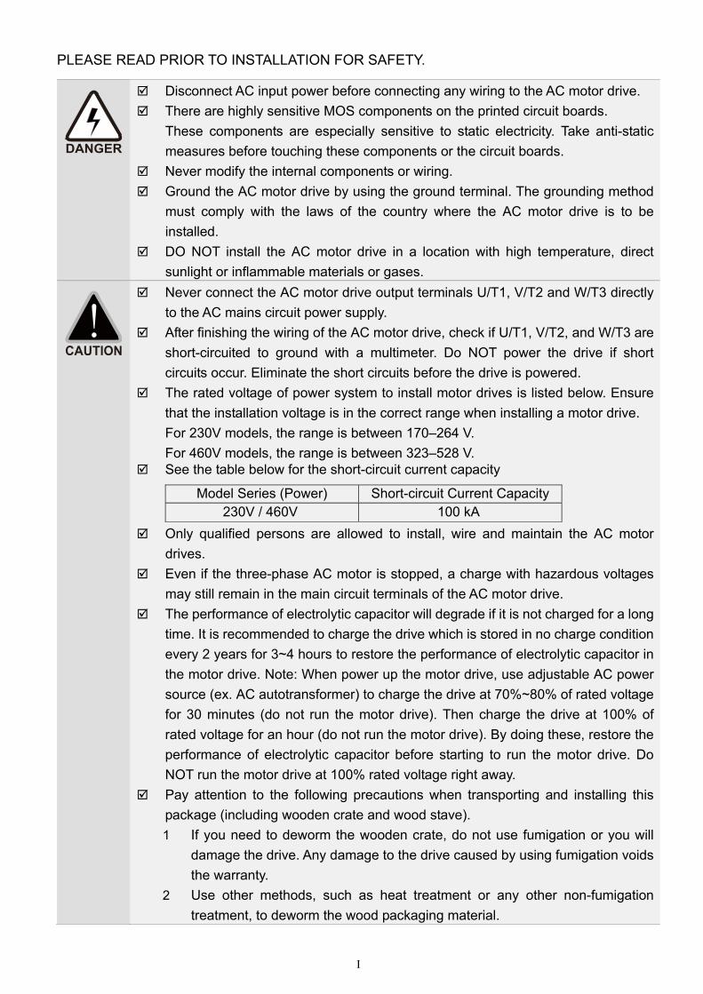
PLEASE READ PRIOR TO INSTALLATION FOR SAFETY.
Disconnect AC input power before connecting any wiring to the AC motor drive. There are highly sensitive MOS components on the printed circuit boards.
These components are especially sensitive to static electricity. Take anti-static measures before touching these components or the circuit boards.
Never modify the internal components or wiring. Ground the AC motor drive by using the ground terminal. The grounding method
must comply with the laws of the country where the AC motor drive is to be installed.
DO NOT install the AC motor drive in a location with high temperature, direct sunlight or inflammable materials or gases.
Never connect the AC motor drive output terminals U/T1, V/T2 and W/T3 directly to the AC mains circuit power supply.
After finishing the wiring of the AC motor drive, check if U/T1, V/T2, and W/T3 are short-circuited to ground with a multimeter. Do NOT power the drive if short circuits occur. Eliminate the short circuits before the drive is powered.
The rated voltage of power system to install motor drives is listed below. Ensure that the installation voltage is in the correct range when installing a motor drive. For 230V models, the range is between 170–264 V. For 460V models, the range is between 323–528 V.
See the table below for the short-circuit current capacity
Model Series (Power) Short-circuit Current Capacity 230V / 460V 100 kA
Only qualified persons are allowed to install, wire and maintain the AC motor drives.
Even if the three-phase AC motor is stopped, a charge with hazardous voltages may still remain in the main circuit terminals of the AC motor drive.
The performance of electrolytic capacitor will degrade if it is not charged for a long time. It is recommended to charge the drive which is stored in no charge condition every 2 years for 3~4 hours to restore the performance of electrolytic capacitor in the motor drive. Note: When power up the motor drive, use adjustable AC power source (ex. AC autotransformer) to charge the drive at 70%~80% of rated voltage for 30 minutes (do not run the motor drive). Then charge the drive at 100% of rated voltage for an hour (do not run the motor drive). By doing these, restore the performance of electrolytic capacitor before starting to run the motor drive. Do NOT run the motor drive at 100% rated voltage right away.
Pay attention to the following precautions when transporting and installing this package (including wooden crate and wood stave). 1 If you need to deworm the wooden crate, do not use fumigation or you will
damage the drive. Any damage to the drive caused by using fumigation voids the warranty.
2 Use other methods, such as heat treatment or any other non-fumigation treatment, to deworm the wood packaging material.
II
3 If you use heat treatment to deworm, leave the packaging materials in an environment of over 56°C for a minimum of thirty minutes.
Connect the drive to a three-phase three-wire or three-phase four-wire Wye system to comply with UL standards.
If the drive generates leakage current over AC 3.5 mA or DC 10 mA on a groundingconductor, compliance with local grounding regulations or IEC61800-5-1 standard is the minimum requirement for grounding.
NOTE In the pictures in this manual, the cover or safety shield is disassembled only when explaining the details
of the product. During operation, install the top cover and wiring correctly according to the provisions. Refer to the operation descriptions in the manual to ensure safety.
The figures in this instruction are only for reference and may be slightly different depending on your model, but it will not affect your customer rights.
The content of this manual may be revised without prior notice. Consult our distributors or download the latest version at http://www.deltaww.com/iadownload_acmotordrive
III
Table of Contents
CHAPTER 1 INTRODUCTION .................................................................................................. 1-1
1-1 Nameplate Information................................................................................................1-2 1-2 Model Name................................................................................................................1-3 1-3 Serial Number..............................................................................................................1-3 1-4 RFI Jumper..................................................................................................................1-4
CHAPTER 2 DIMENSION ......................................................................................................... 2-1
2-1 Frame A…………………………………………………..……………………………………2-2 2-2 Frame B…………………………………………………………..……………………………2-3 2-3 Frame C…...……………………………………………………..……………………………2-4 2-4 Dimensions and Models for Plastic Cable Glands………..………………………………2-5
CHAPTER 3 INSTALLATION ................................................................................................... 3-1
3-1 Minimum Mounting Clearance and Installation............................................................3-2 3-2 Airflow Rate for Cooling and Power Dissipation...........................................................3-3
CHAPTER 4 WIRING ................................................................................................................ 4-1
4-1 System Wiring Diagram...............................................................................................4-3 4-2 Wiring...........................................................................................................................4-4
CHAPTER 5 MAIN CIRCUIT TERMINALS ............................................................................. 5-1
5-1 Main Circuit Diagram....................................................................................................5-4 5-2 Main Circuit Terminals..................................................................................................5-5
CHPATER 6 CONTROL TERMINALS ...................................................................................... 6-1
6-1 Control Circuit Terminals Specifications ......................................................................6-2
CHAPTER 7 OPTIONAL ACCESSORIES ................................................................................ 7-1
7-1 All Brake Resistors and Brake Units Used in AC Motor Drives...................................7-2 7-2 Non-fuse Circuit Breaker.............................................................................................7-4 7-3 Fuse Specification Chart ............................................................................................7-5 7-4 AC/DC Reactor............................................................................................................7-7 7-5 Zero Phase Reactors................................................................................................7-17 7-6 EMC Filter.................................................................................................................7-20 7-7 EMC Shield Plate......................................................................................................7-23 7-8 Capacitive Filter.........................................................................................................7-30 7-9 Fan Kit.......................................................................................................................7-31 7-10 Main Switch…………. …….....................................................................................7-46
IV
CHAPTER 8 OPTION CARDS ................................................................................................. 8-1
8-1 Option Card Installation................................................................................................8-2 8-2 CMM-MOD01 -- Communication Extension Card, Modbus TCP...........................................8-7 8-3 CMM-PD01 -- Communication Extension Card, PROFIBUS DP.........................................8-10 8-4 CMM-DN01 -- Communication Extension Card, DeviceNet................................................8-12 8-5 CMM-EIP01 -- Communication Extension Card, EtherNet/IP..............................................8-15 8-6 CMM-COP01 -- Communication Extension Card, CANopen..............................................8-18 8-7 EMM-BPS01 -- +24 V Power Extension Card..................................................................8-19
8-8 Delta Bus Standard Wire………………………………………………………...…….….8-20
CHAPTER 9 SPECIFICATIONS ............................................................................................... 9-1
9-1 230V Series………………………………......................................................................9-2 9-2 460V Series………………………………......................................................................9-4 9-3 Environment for Operation, Storage and Transportation…………………….................9-6 9-4 Derating for Ambient Temperature and Altitude……………………...............................9-7
CHAPTER 10 DIGITAL KEYPAD ........................................................................................... 10-1
CHAPTER 11 SUMMARY OF PARAMETERS SETTINGS .................................................... 11-1
CHAPTER 12 DESCRIPTION OF PARAMETER SETTINGS ................................................ 12-1
CHAPTER 13 WARNING CODES ......................................................................................... 13-1
CHAPTER 14 ERROR CODES .............................................................................................. 14-1
CHAPTER 15 CANOPEN OVERVIEW .................................................................................. 15-1
CHAPTER 16 PLC FUNCTION APPLICATIONS ................................................................... 16-1
CHAPTER 17 SAFE TORQUE OFF FUNCTION….………………………..……….……………17-1
Issued Edition: 01
Firmware Version: V1.08 (Refer to Parameter 00-06 on the product to get the firmware version.)
Issued Date: 2019/1
Chapter 1 IntroductionMS300 (IP66 / NEMA 4X)
1-1
Chapter 1 Introduction
1-1 Nameplate Information
1-2 Model Name
1-3 Serial Number
1-4 RFI Jumper
Chapter 1 Introduction MS300 (IP66 / NEMA 4X)
1-2
After receiving the AC motor drive, check for the following:
1. Inspect the unit after unpacking to ensure that it was not damaged during shipment. Make sure that the part number printed on the package matches the part number indicated on the nameplate.
2. Make sure that the mains voltage is within the range indicated on the nameplate. Install the AC motor drive according to the instructions in this manual.
3. Before applying power, make sure that all devices, including mains power, motor, control board and digital keypad, are connected correctly.
4. When wiring the AC motor drive, make sure that the wiring for input terminals “R/L1, S/L2, T/L3”, and output terminals “U/T1, V/T2, W/T3” are correct to prevent damage to the drive.
5. When power is applied, use the digital keypad to select the language and set parameters. When executing a trial run, begin with a low speed and then gradually increase the speed to the desired speed.
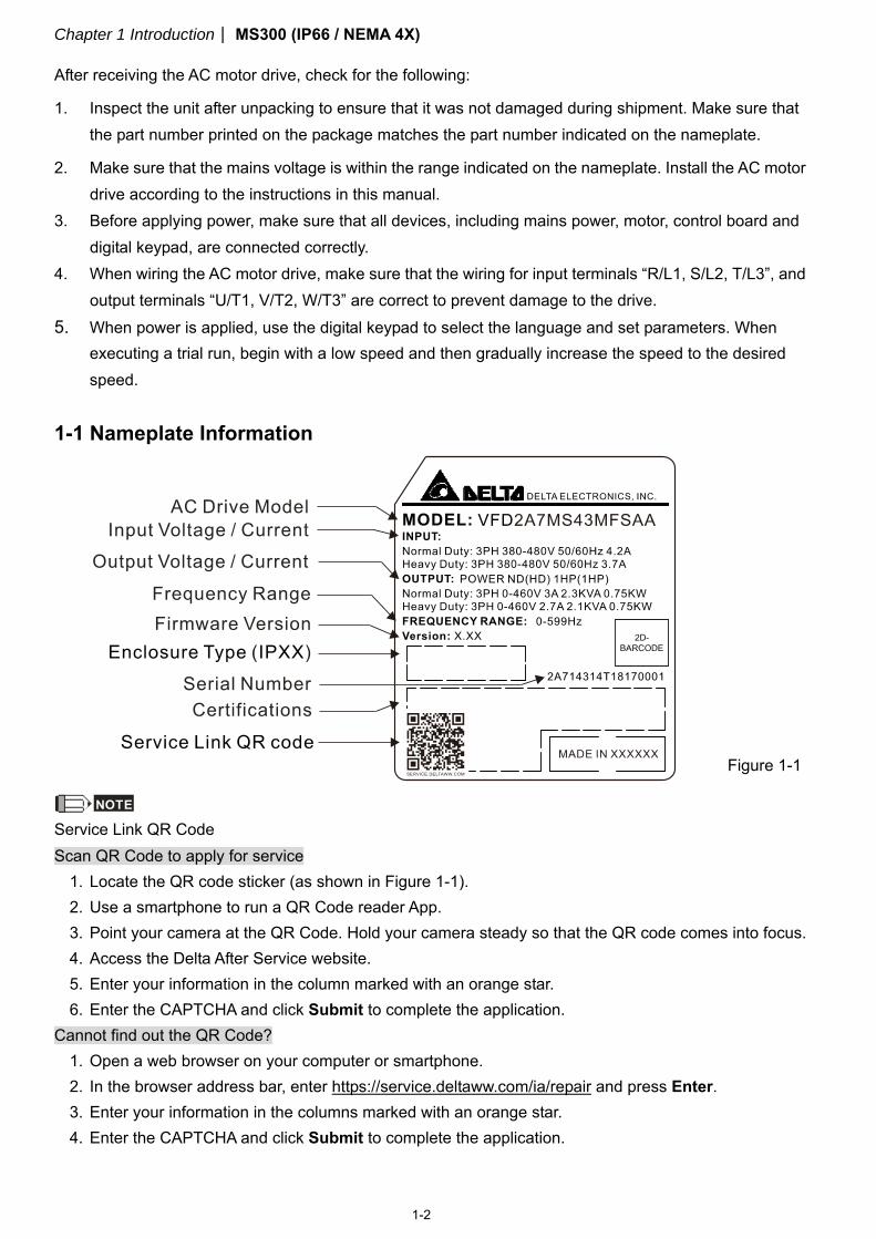
1-1 Nameplate Information
NOTE
Service Link QR Code Scan QR Code to apply for service
1. Locate the QR code sticker (as shown in Figure 1-1). 2. Use a smartphone to run a QR Code reader App. 3. Point your camera at the QR Code. Hold your camera steady so that the QR code comes into focus. 4. Access the Delta After Service website. 5. Enter your information in the column marked with an orange star. 6. Enter the CAPTCHA and click Submit to complete the application.
Cannot find out the QR Code? 1. Open a web browser on your computer or smartphone. 2. In the browser address bar, enter https://service.deltaww.com/ia/repair and press Enter. 3. Enter your information in the columns marked with an orange star. 4. Enter the CAPTCHA and click Submit to complete the application.
Figure 1-1
Chapter 1 IntroductionMS300 (IP66 / NEMA 4X)
1-3
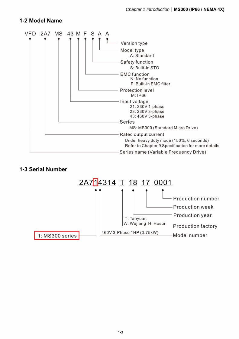
1-2 Model Name
1-3 Serial Number
Chapter 1 Introduction MS300 (IP66 / NEMA 4X)
1-4
1-4 RFI Jumper
The drive contains Varistors/MOVs that are connected from phase to phase and from phase to ground to protect the drive against mains surges or voltage spikes. Because the Varistors/MOVs from phase to ground are connected to ground with the RFI jumper, removing the RFI jumper disables the protection.
(1) In models with a built-in EMC filter, the RFI jumper connects the filter capacitors to ground to form a return path for high frequency noise. This isolates the noise from contaminating the mains power. Removing the RFI jumper strongly reduces the effect of the built-in EMC filter.
(2) Although a single drive complies with the international standards for leakage current, an installation with several drives with built-in EMC filters can trigger the RCD. Removing the RFI jumper can help, but the EMC performance of each drive is no longer guaranteed.
(3) Description for removing and connecting the RFI jumper.
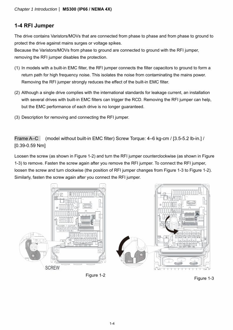
Frame A–C (model without built-in EMC filter) Screw Torque: 4–6 kg-cm / [3.5-5.2 lb-in.] / [0.39-0.59 Nm]
Loosen the screw (as shown in Figure 1-2) and turn the RFI jumper counterclockwise (as shown in Figure 1-3) to remove. Fasten the screw again after you remove the RFI jumper. To connect the RFI jumper, loosen the screw and turn clockwise (the position of RFI jumper changes from Figure 1-3 to Figure 1-2). Similarly, fasten the screw again after you connect the RFI jumper.
Figure 1-2 Figure 1-3
Chapter 1 IntroductionMS300 (IP66 / NEMA 4X)
1-5
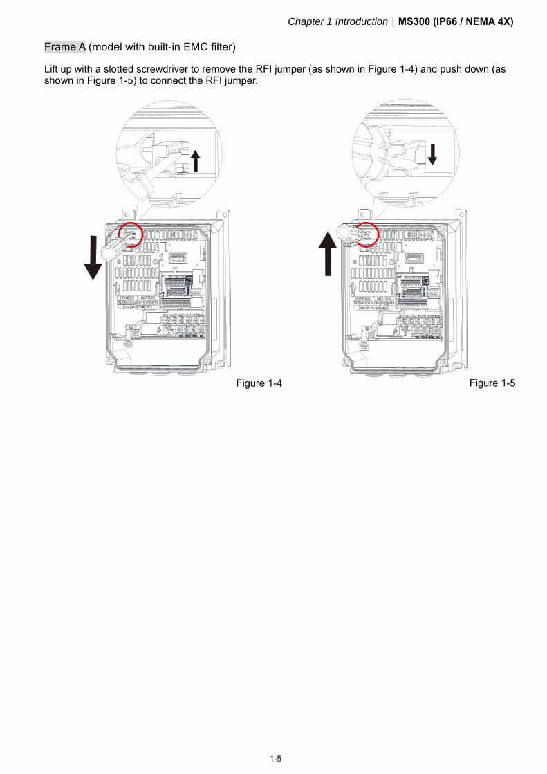
Frame A (model with built-in EMC filter)
Lift up with a slotted screwdriver to remove the RFI jumper (as shown in Figure 1-4) and push down (as shown in Figure 1-5) to connect the RFI jumper.
Figure 1-4 Figure 1-5
Chapter 1 Introduction MS300 (IP66 / NEMA 4X)
1-6
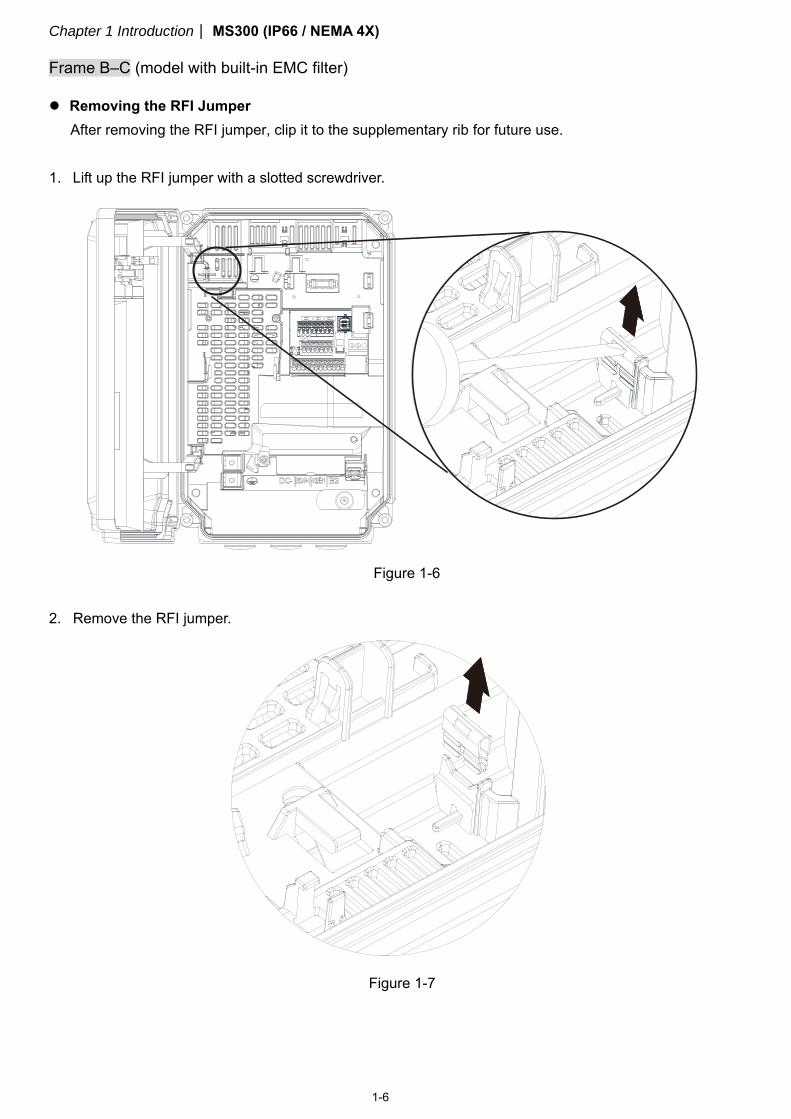
Frame B–C (model with built-in EMC filter)
Removing the RFI Jumper
After removing the RFI jumper, clip it to the supplementary rib for future use. 1. Lift up the RFI jumper with a slotted screwdriver.
2. Remove the RFI jumper.
Figure 1-6
Figure 1-7
Chapter 1 IntroductionMS300 (IP66 / NEMA 4X)
1-7
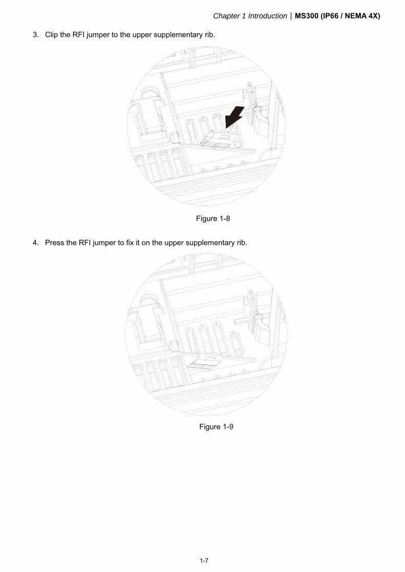
3. Clip the RFI jumper to the upper supplementary rib.
4. Press the RFI jumper to fix it on the upper supplementary rib.
Figure 1-8
Figure 1-9
Chapter 1 Introduction MS300 (IP66 / NEMA 4X)
1-8
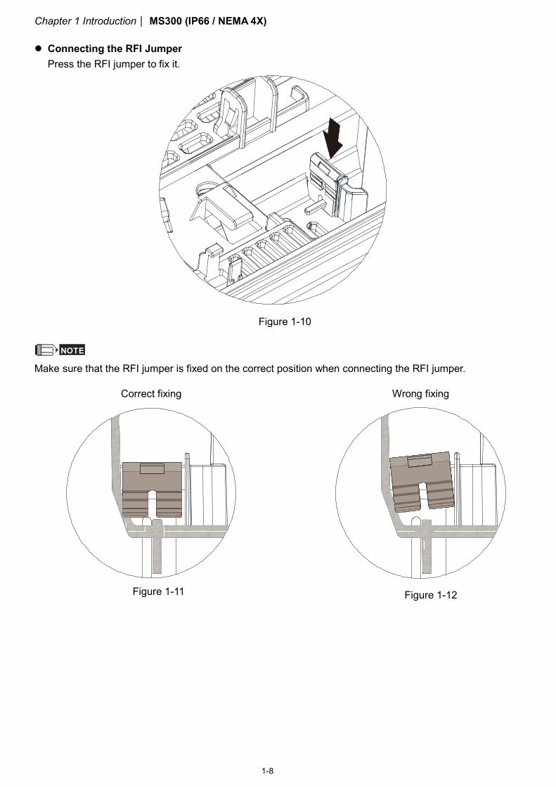
Connecting the RFI Jumper
Press the RFI jumper to fix it.
NOTE Make sure that the RFI jumper is fixed on the correct position when connecting the RFI jumper.
Correct fixing
Wrong fixing
Figure 1-10
Figure 1-11 Figure 1-12
Chapter 1 IntroductionMS300 (IP66 / NEMA 4X)
1-9
Isolating main power from ground:
When the power distribution system for the drive is a floating ground system (IT Systems) or an asymmetric ground system (Corner Grounded TN Systems), you must remove the RFI jumper. Removing the RFI jumper disconnects the internal capacitors from ground to avoid damaging the internal circuits and to reduce the ground leakage current.
Important points regarding ground connection:
To ensure the safety of personnel, proper operation, and to reduce electromagnetic radiation, you must properly ground the drive during installation.
The diameter of the cables must comply with the local safety regulations. The shields of shielded cables must be connected to the ground of the drive to meet safety
regulations. The shields of shielded power cables can only be used as the ground for equipment when the above
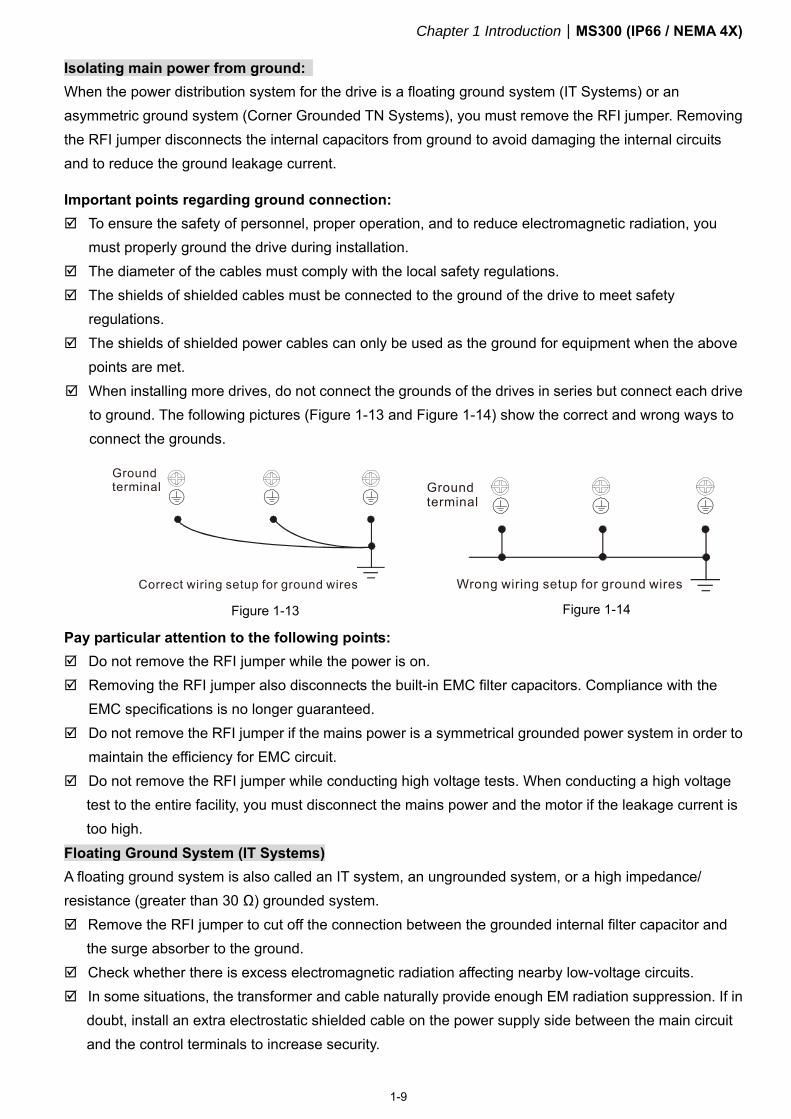
points are met. When installing more drives, do not connect the grounds of the drives in series but connect each drive
to ground. The following pictures (Figure 1-13 and Figure 1-14) show the correct and wrong ways to connect the grounds.
Pay particular attention to the following points:
Do not remove the RFI jumper while the power is on. Removing the RFI jumper also disconnects the built-in EMC filter capacitors. Compliance with the
EMC specifications is no longer guaranteed. Do not remove the RFI jumper if the mains power is a symmetrical grounded power system in order to
maintain the efficiency for EMC circuit. Do not remove the RFI jumper while conducting high voltage tests. When conducting a high voltage
test to the entire facility, you must disconnect the mains power and the motor if the leakage current is too high.
Floating Ground System (IT Systems)
A floating ground system is also called an IT system, an ungrounded system, or a high impedance/ resistance (greater than 30 Ω) grounded system. Remove the RFI jumper to cut off the connection between the grounded internal filter capacitor and
the surge absorber to the ground. Check whether there is excess electromagnetic radiation affecting nearby low-voltage circuits. In some situations, the transformer and cable naturally provide enough EM radiation suppression. If in
doubt, install an extra electrostatic shielded cable on the power supply side between the main circuit and the control terminals to increase security.
Figure 1-14 Figure 1-13
Chapter 1 Introduction MS300 (IP66 / NEMA 4X)
1-10
Do not install an external EMC filter. The EMC filter is connected to ground through the filter capacitors, and connects the power input to ground. This is very dangerous and can easily damage the drive.
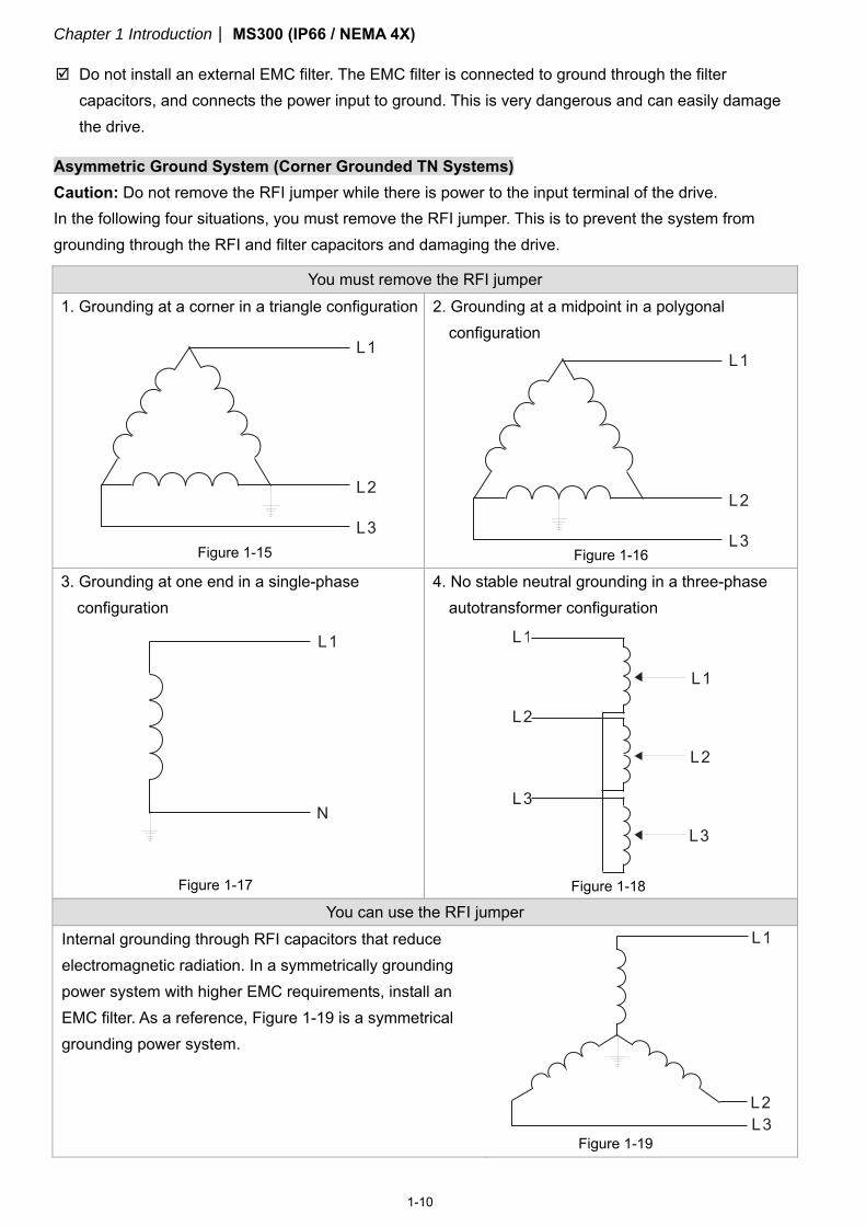
Asymmetric Ground System (Corner Grounded TN Systems)
Caution: Do not remove the RFI jumper while there is power to the input terminal of the drive. In the following four situations, you must remove the RFI jumper. This is to prevent the system from grounding through the RFI and filter capacitors and damaging the drive.
You must remove the RFI jumper 1. Grounding at a corner in a triangle configuration
L2
L3
L1
2. Grounding at a midpoint in a polygonal configuration
L2
L3
L1
3. Grounding at one end in a single-phase configuration
L1
N
4. No stable neutral grounding in a three-phase autotransformer configuration
L1
L2
L3
L1
L2
L3
You can use the RFI jumper Internal grounding through RFI capacitors that reduce electromagnetic radiation. In a symmetrically grounding power system with higher EMC requirements, install an EMC filter. As a reference, Figure 1-19 is a symmetrical grounding power system.
L2L3
L1
Figure 1-15 Figure 1-16
Figure 1-17 Figure 1-18
Figure 1-19

Chapter 1 IntroductionMS300 (IP66 / NEMA 4X)
1-11
[This page intentionally left blank]
Chapter 2 DimensionsMS300 (IP66 / NEMA 4X)
2-1
Chapter 2 Dimensions
2-1 Frame A
2-2 Frame B
2-3 Frame C
2-4 Dimensions and Models for Plastic Cable Glands
Chapter 2 DimensionsMS300 (IP66 / NEMA 4X)
2-2
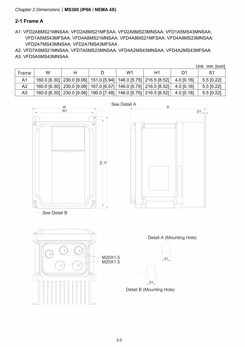
2-1 Frame A
A1: VFD2A8MS21MNSAA; VFD2A8MS21MFSAA; VFD2A8MS23MNSAA; VFD1A5MS43MNSAA; VFD1A5MS43MFSAA; VFD4A8MS21MNSAA; VFD4A8MS21MFSAA; VFD4A8MS23MNSAA; VFD2A7MS43MNSAA; VFD2A7MS43MFSAA
A2: VFD7A5MS21MNSAA; VFD7A5MS23MNSAA; VFD4A2MS43MNSAA; VFD4A2MS43MFSAA A3: VFD5A5MS43MNSAA
Unit: mm [inch]
Frame W H D W1 H1 D1 S1 A1 160.0 [6.30] 230.0 [9.06] 151.0 [5.94] 146.0 [5.75] 216.5 [8.52] 4.0 [0.16] 5.5 [0.22] A2 160.0 [6.30] 230.0 [9.06] 167.0 [6.57] 146.0 [5.75] 216.5 [8.52] 4.0 [0.16] 5.5 [0.22] A3 160.0 [6.30] 230.0 [9.06] 190.0 [7.48] 146.0 [5.75] 216.5 [8.52] 4.0 [0.16] 5.5 [0.22]
H
1
D
Detail B (Mounting Hole)
H
D1
See Detail B
W1
See Detail A
M20X1.5
W
Detail A (Mounting Hole)
M25X1.5S1
S1
Chapter 2 DimensionsMS300 (IP66 / NEMA 4X)
2-3
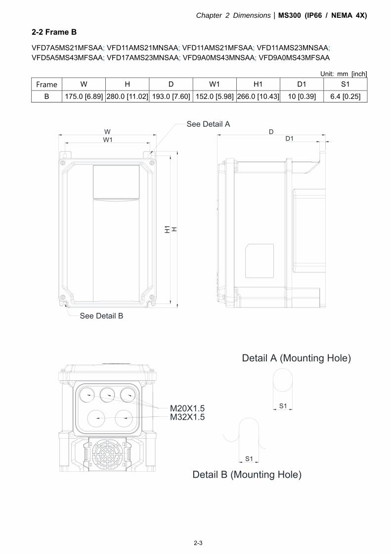
2-2 Frame B
VFD7A5MS21MFSAA; VFD11AMS21MNSAA; VFD11AMS21MFSAA; VFD11AMS23MNSAA; VFD5A5MS43MFSAA; VFD17AMS23MNSAA; VFD9A0MS43MNSAA; VFD9A0MS43MFSAA
Unit: mm [inch] Frame W H D W1 H1 D1 S1
B 175.0 [6.89] 280.0 [11.02] 193.0 [7.60] 152.0 [5.98] 266.0 [10.43] 10 [0.39] 6.4 [0.25]
H
M20X1.5
Detail A (Mounting Hole)
Detail B (Mounting Hole)
See Detail AD
M32X1.5
S1
See Detail B
D1W1
H1
W
S1
Chapter 2 DimensionsMS300 (IP66 / NEMA 4X)
2-4
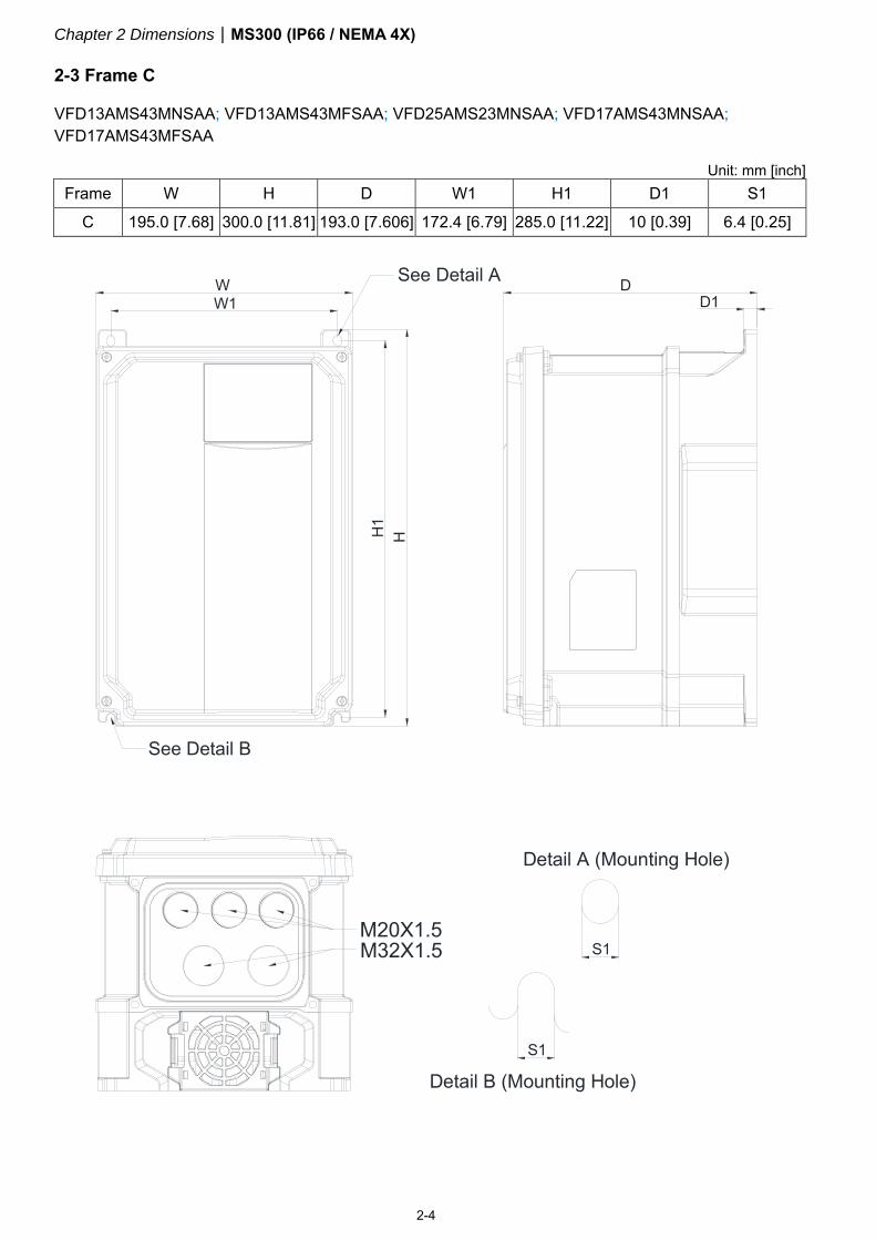
2-3 Frame C
VFD13AMS43MNSAA; VFD13AMS43MFSAA; VFD25AMS23MNSAA; VFD17AMS43MNSAA; VFD17AMS43MFSAA
Unit: mm [inch]
Frame W H D W1 H1 D1 S1
C 195.0 [7.68] 300.0 [11.81] 193.0 [7.606] 172.4 [6.79] 285.0 [11.22] 10 [0.39] 6.4 [0.25]
S1
W
H1
M20X1.5
H
D1D
M32X1.5 S1
W1
Detail A (Mounting Hole)
Detail B (Mounting Hole)
See Detail B
See Detail A
Chapter 2 DimensionsMS300 (IP66 / NEMA 4X)
2-5
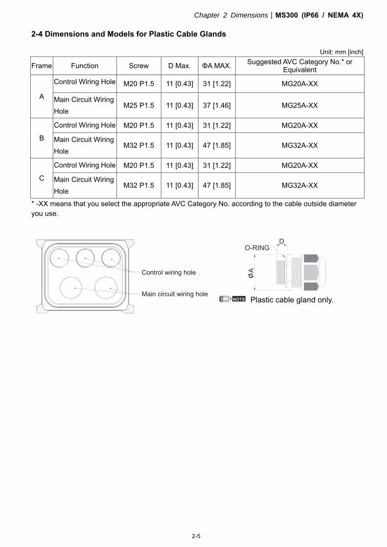
2-4 Dimensions and Models for Plastic Cable Glands
Unit: mm [inch]
Frame Function Screw D Max. ΦA MAX. Suggested AVC Category No.* or Equivalent
A
Control Wiring Hole M20 P1.5 11 [0.43] 31 [1.22] MG20A-XX
Main Circuit Wiring Hole
M25 P1.5 11 [0.43] 37 [1.46] MG25A-XX
B
Control Wiring Hole M20 P1.5 11 [0.43] 31 [1.22] MG20A-XX
Main Circuit Wiring Hole
M32 P1.5 11 [0.43] 47 [1.85] MG32A-XX
C
Control Wiring Hole M20 P1.5 11 [0.43] 31 [1.22] MG20A-XX
Main Circuit Wiring Hole
M32 P1.5 11 [0.43] 47 [1.85] MG32A-XX
* -XX means that you select the appropriate AVC Category No. according to the cable outside diameter you use.
NOTE Plastic cable gland only.

Chapter 2 DimensionsMS300 (IP66 / NEMA 4X)
2-6
[This page intentionally left blank]

Chapter 3 InstallationMS300 (IP66 / NEMA 4X)
3-1
Chapter 3 Installation
3-1 Minimum Mounting Clearance and Installation
3-2 Airflow Rate for Cooling and Power Dissipation
Chapter 3 InstallationMS300 (IP66 / NEMA 4X)
3-2
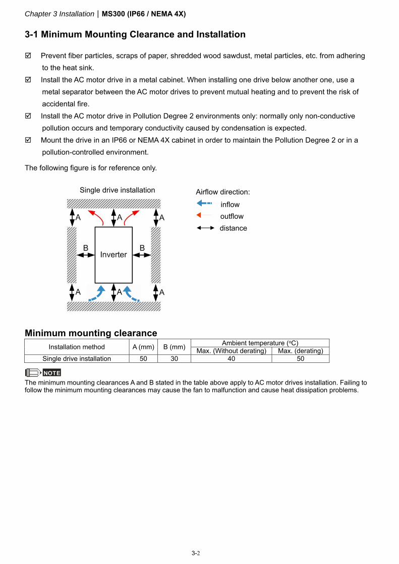
3-1 Minimum Mounting Clearance and Installation
Prevent fiber particles, scraps of paper, shredded wood sawdust, metal particles, etc. from adhering to the heat sink.
Install the AC motor drive in a metal cabinet. When installing one drive below another one, use a metal separator between the AC motor drives to prevent mutual heating and to prevent the risk of accidental fire.
Install the AC motor drive in Pollution Degree 2 environments only: normally only non-conductive pollution occurs and temporary conductivity caused by condensation is expected.
Mount the drive in an IP66 or NEMA 4X cabinet in order to maintain the Pollution Degree 2 or in a pollution-controlled environment.
The following figure is for reference only.
Single drive installation
Airflow direction:
inflow outflow
distance
Minimum mounting clearance
Installation method A (mm) B (mm) Ambient temperature (oC) Max. (Without derating) Max. (derating)
Single drive installation 50 30 40 50
NOTE The minimum mounting clearances A and B stated in the table above apply to AC motor drives installation. Failing to follow the minimum mounting clearances may cause the fan to malfunction and cause heat dissipation problems.
Chapter 3 InstallationMS300 (IP66 / NEMA 4X)
3-3
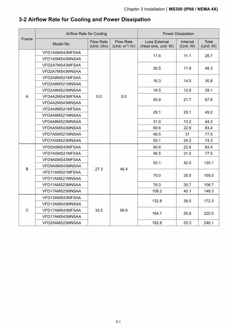
3-2 Airflow Rate for Cooling and Power Dissipation
Frame Airflow Rate for Cooling Power Dissipation
Model No. Flow Rate (Unit: cfm)
Flow Rate (Unit: m3 / hr)
Loss External (Heat sink, unit: W)
Internal (Unit: W)
Total (Unit: W)
A
VFD1A5MS43MFSAA
0.0 0.0
17.6 11.1 28.7 VFD1A5MS43MNSAA VFD2A7MS43MFSAA
30.5 17.8 48.3 VFD2A7MS43MNSAA VFD2A8MS21MFSAA
16.3 14.5 30.8 VFD2A8MS21MNSAA VFD2A8MS23MNSAA 16.5 12.6 29.1 VFD4A2MS43MFSAA
45.9 21.7 67.6 VFD4A2MS43MNSAA VFD4A8MS21MFSAA
29.1 20.1 49.2 VFD4A8MS21MNSAA VFD4A8MS23MNSAA 31.0 13.2 44.2 VFD5A5MS43MNSAA 60.6 22.8 83.4 VFD7A5MS21MNSAA 46.5 31 77.5 VFD7A5MS23MNSAA 50.1 24.2 74.3
B
VFD5A5MS43MFSAA
27.3 46.4
60.6 22.8 83.4 VFD7A5MS21MFSAA 46.5 31.0 77.5 VFD9A0MS43MFSAA
93.1 42.0 135.1 VFD9A0MS43MNSAA VFD11AMS21MFSAA
70.0 35.0 105.0 VFD11AMS21MNSAA VFD11AMS23MNSAA 76.0 30.7 106.7 VFD17AMS23MNSAA 108.2 40.1 148.3
C
VFD13AMS43MFSAA
33.5 56.6
132.8 39.5 172.3 VFD13AMS43MNSAA VFD17AMS43MFSAA
164.7 55.8 220.5 VFD17AMS43MNSAA VFD25AMS23MNSAA 192.8 53.3 246.1

Chapter 3 InstallationMS300 (IP66 / NEMA 4X)
3-4
[This page intentionally left blank]

Chapter 4 WiringMS300 (IP66/NEMA 4X)
4-1
Chapter 4 Wiring
4-1 System Wiring Diagram
4-2 Wiring
Chapter 4 WiringMS300 (IP66/NEMA 4X)
4-2
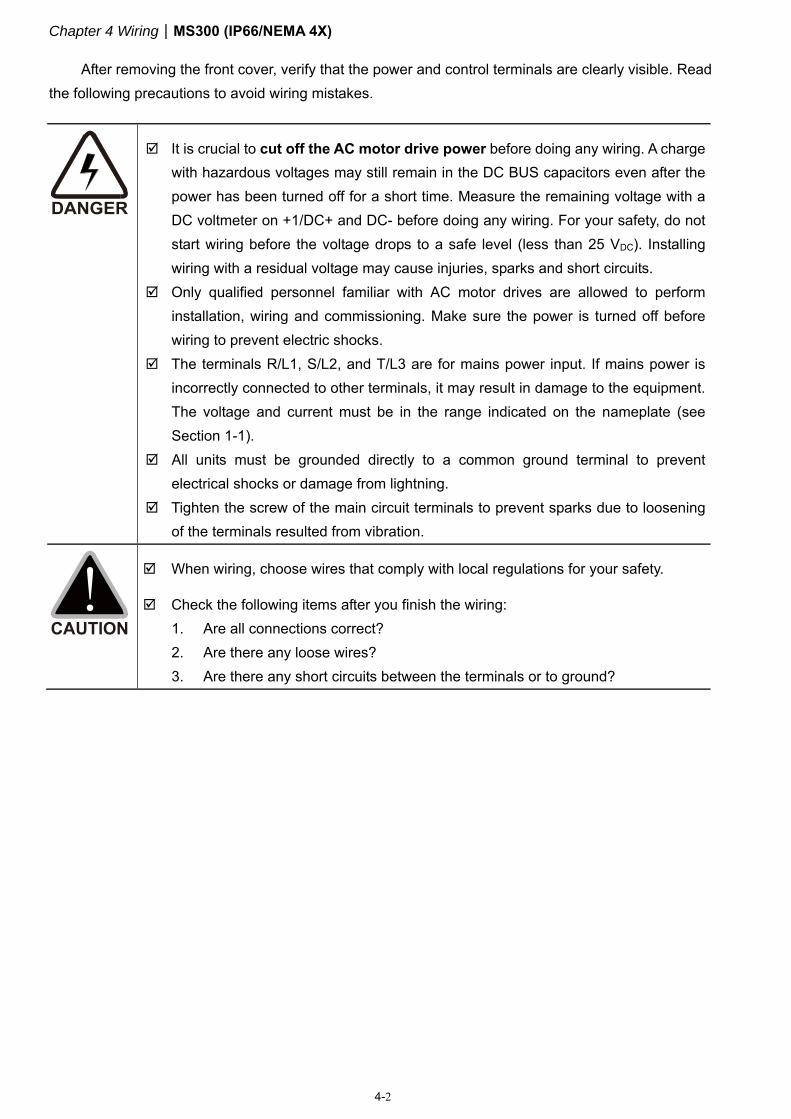
After removing the front cover, verify that the power and control terminals are clearly visible. Read the following precautions to avoid wiring mistakes.
It is crucial to cut off the AC motor drive power before doing any wiring. A charge with hazardous voltages may still remain in the DC BUS capacitors even after the power has been turned off for a short time. Measure the remaining voltage with a DC voltmeter on +1/DC+ and DC- before doing any wiring. For your safety, do not start wiring before the voltage drops to a safe level (less than 25 VDC). Installing wiring with a residual voltage may cause injuries, sparks and short circuits.
Only qualified personnel familiar with AC motor drives are allowed to perform installation, wiring and commissioning. Make sure the power is turned off before wiring to prevent electric shocks.
The terminals R/L1, S/L2, and T/L3 are for mains power input. If mains power is incorrectly connected to other terminals, it may result in damage to the equipment. The voltage and current must be in the range indicated on the nameplate (see Section 1-1).
All units must be grounded directly to a common ground terminal to prevent electrical shocks or damage from lightning.
Tighten the screw of the main circuit terminals to prevent sparks due to loosening of the terminals resulted from vibration.
When wiring, choose wires that comply with local regulations for your safety.
Check the following items after you finish the wiring: 1. Are all connections correct? 2. Are there any loose wires? 3. Are there any short circuits between the terminals or to ground?
Chapter 4 WiringMS300 (IP66/NEMA 4X)
4-3
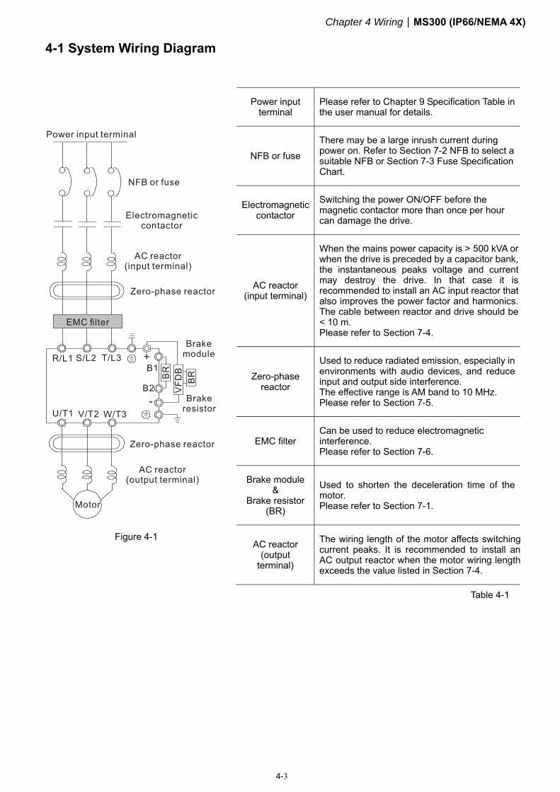
4-1 System Wiring Diagram
Figure 4-1
Power input terminal
Please refer to Chapter 9 Specification Table in the user manual for details.
NFB or fuse There may be a large inrush current during power on. Refer to Section 7-2 NFB to select a suitable NFB or Section 7-3 Fuse Specification Chart.
Electromagnetic contactor
Switching the power ON/OFF before the magnetic contactor more than once per hour can damage the drive.
AC reactor (input terminal)
When the mains power capacity is > 500 kVA or when the drive is preceded by a capacitor bank, the instantaneous peaks voltage and current may destroy the drive. In that case it is recommended to install an AC input reactor that also improves the power factor and harmonics. The cable between reactor and drive should be < 10 m. Please refer to Section 7-4.
Zero-phase reactor
Used to reduce radiated emission, especially in environments with audio devices, and reduce input and output side interference. The effective range is AM band to 10 MHz. Please refer to Section 7-5.
EMC filter Can be used to reduce electromagnetic interference. Please refer to Section 7-6.
Brake module &
Brake resistor (BR)
Used to shorten the deceleration time of the motor. Please refer to Section 7-1.
AC reactor (output
terminal)
The wiring length of the motor affects switchingcurrent peaks. It is recommended to install anAC output reactor when the motor wiring lengthexceeds the value listed in Section 7-4.
Table 4-1
Chapter 4 WiringMS300 (IP66/NEMA 4X)
4-4
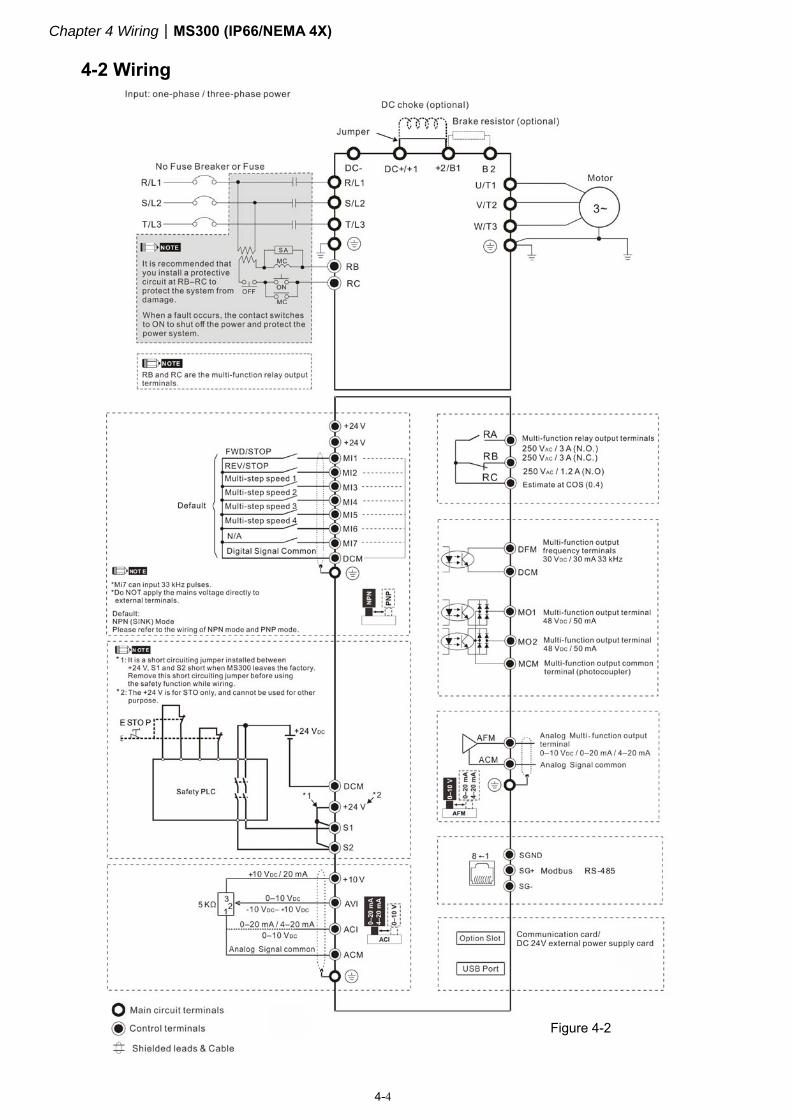
4-2 Wiring
Figure 4-2
Chapter 4 WiringMS300 (IP66/NEMA 4X)
4-5
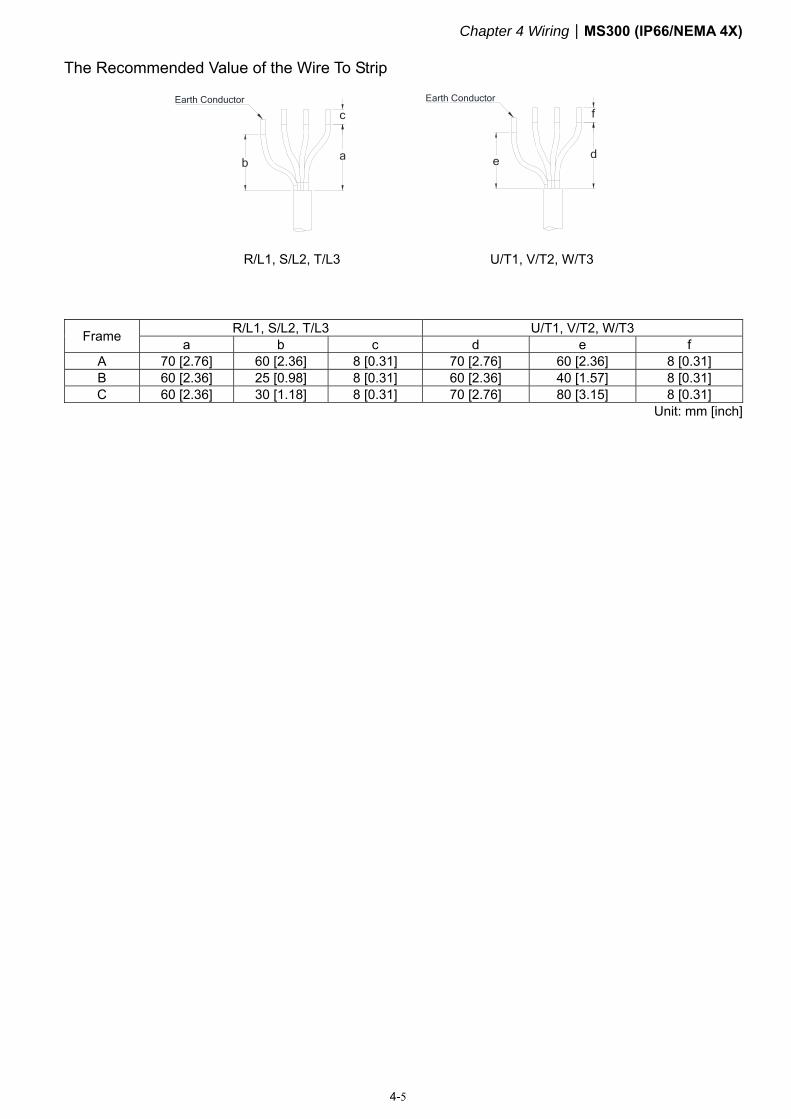
The Recommended Value of the Wire To Strip
c
a
Earth Conductor
b
R/L1, S/L2, T/L3
d
Earth Conductor
f
e
U/T1, V/T2, W/T3
Frame R/L1, S/L2, T/L3 U/T1, V/T2, W/T3 a b c d e f
A 70 [2.76] 60 [2.36] 8 [0.31] 70 [2.76] 60 [2.36] 8 [0.31] B 60 [2.36] 25 [0.98] 8 [0.31] 60 [2.36] 40 [1.57] 8 [0.31] C 60 [2.36] 30 [1.18] 8 [0.31] 70 [2.76] 80 [3.15] 8 [0.31]
Unit: mm [inch]

Chapter 4 WiringMS300 (IP66/NEMA 4X)
4-6
[This page intentionally left blank]

Chapter 5 Main Circuit TerminalsMS300 (IP66 / NEMA 4X)
5-1
Chapter 5 Main Circuit Terminals
5-1 Main Circuit Diagram
5-2 Main Circuit Terminals
Chapter 5 Main Circuit TerminalsMS300 (IP66 / NEMA 4X)
5-2
DANGER
Securely fasten the main circuit terminal screws to prevent sparking caused by loose screws due to vibration.
When needed, only use an inductive filter at the motor output terminals U/T1, V/T2, W/T3 of the AC motor drive. DO NOT use phase-compensation capacitors or L-C (Inductance-Capacitance) or R-C (Resistance-Capacitance), unless approved by Delta.
DO NOT connect brake resistors directly to +1/DC+ to DC-, +2/B1 to DC- to prevent damage to the drive.
Ensure proper insulation of the main circuit wiring in accordance with the relevant safety regulations.
Main power terminals DO NOT connect the three-phase drive to one-phase power. R/L1, S/L2
and T/L3 have no phase-sequence requirement; they can be connected in any sequence.
Add a magnetic contactor (MC) at the power input to quickly cut off power and reduce malfunction when activating AC motor drive protection function. Both ends of the MC should have an R-C surge absorber.
Ensure that voltages and currents are within specification. Refer to Chapter 09 Specifications for details.
When using a general GFCI (Ground Fault Circuit Interrupter), select a sensitivity greater than or equal to 200 mA and greater than or equal to 0.1 sec. operation time to avoid nuisance tripping.
Use conduits or shielded cables for the power wiring, and ground both ends of the conduit or shielded cables.
DO NOT start or stop the drive by turning the power ON or OFF. Start and stop the drive with the RUN/STOP command. If you still need to run or stop the drive by turning power ON or OFF, it is strongly recommended that you do so no more often than ONCE per hour.
To comply with UL standards, connect the drive to a three-phase three-wire or three-phase four-wire Wye system type of mains power system.
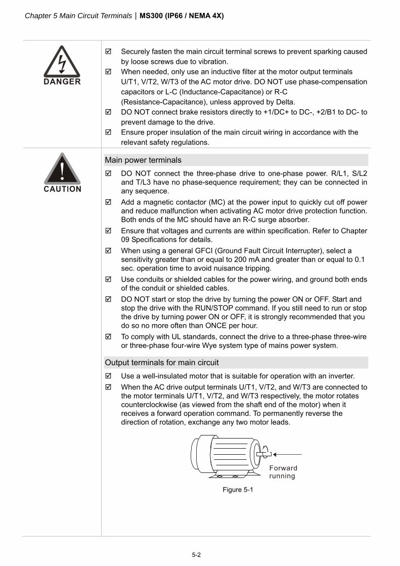
Output terminals for main circuit Use a well-insulated motor that is suitable for operation with an inverter. When the AC drive output terminals U/T1, V/T2, and W/T3 are connected to
the motor terminals U/T1, V/T2, and W/T3 respectively, the motor rotates counterclockwise (as viewed from the shaft end of the motor) when it receives a forward operation command. To permanently reverse the direction of rotation, exchange any two motor leads.
Figure 5-1
Chapter 5 Main Circuit TerminalsMS300 (IP66 / NEMA 4X)
5-3
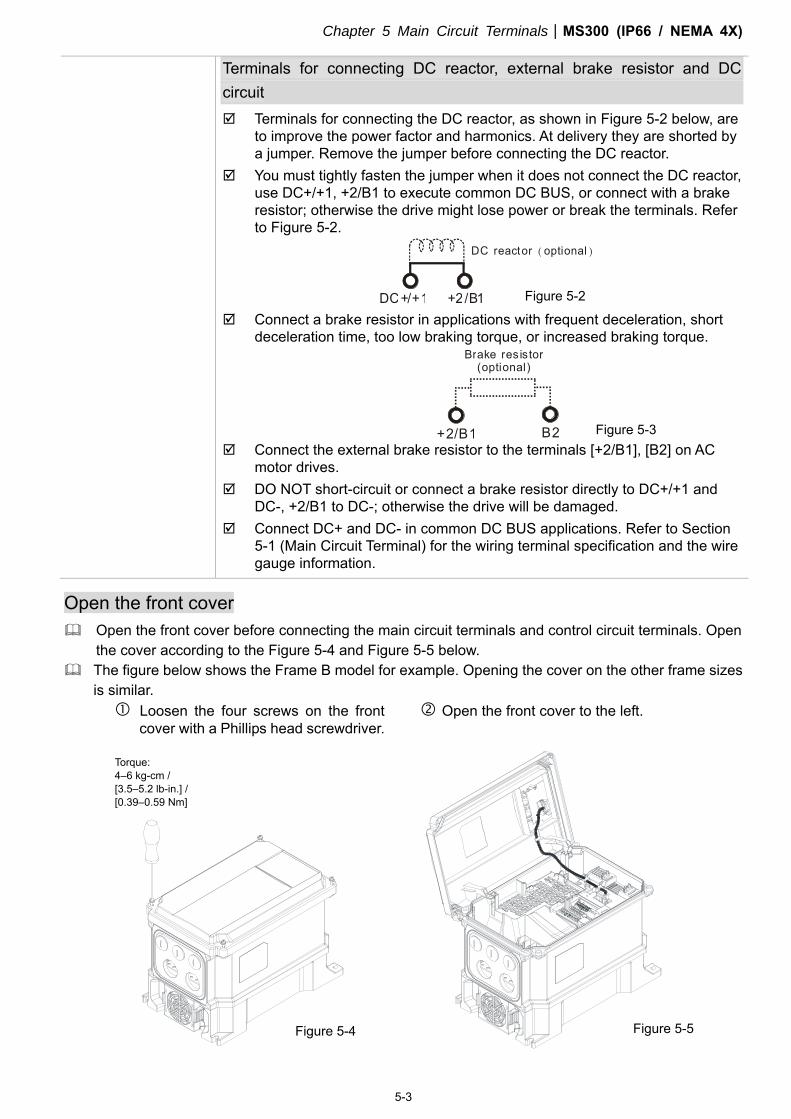
Terminals for connecting DC reactor, external brake resistor and DC circuit Terminals for connecting the DC reactor, as shown in Figure 5-2 below, are
to improve the power factor and harmonics. At delivery they are shorted by a jumper. Remove the jumper before connecting the DC reactor.
You must tightly fasten the jumper when it does not connect the DC reactor, use DC+/+1, +2/B1 to execute common DC BUS, or connect with a brake resistor; otherwise the drive might lose power or break the terminals. Refer to Figure 5-2.
DC reactor optional ( )
DC+/+1 +2/B1 Connect a brake resistor in applications with frequent deceleration, short
deceleration time, too low braking torque, or increased braking torque. Brake resistor
(optional)
+2/B1 B2 Connect the external brake resistor to the terminals [+2/B1], [B2] on AC
motor drives. DO NOT short-circuit or connect a brake resistor directly to DC+/+1 and
DC-, +2/B1 to DC-; otherwise the drive will be damaged. Connect DC+ and DC- in common DC BUS applications. Refer to Section
5-1 (Main Circuit Terminal) for the wiring terminal specification and the wire gauge information.
Open the front cover Open the front cover before connecting the main circuit terminals and control circuit terminals. Open
the cover according to the Figure 5-4 and Figure 5-5 below. The figure below shows the Frame B model for example. Opening the cover on the other frame sizes
is similar. Loosen the four screws on the front
cover with a Phillips head screwdriver. Open the front cover to the left.
Figure 5-4 Figure 5-5
Torque: 4–6 kg-cm / [3.5–5.2 lb-in.] / [0.39–0.59 Nm]
Figure 5-3
Figure 5-2
Chapter 5 Main Circuit TerminalsMS300 (IP66 / NEMA 4X)
5-4
5-1 Main Circuit Diagram
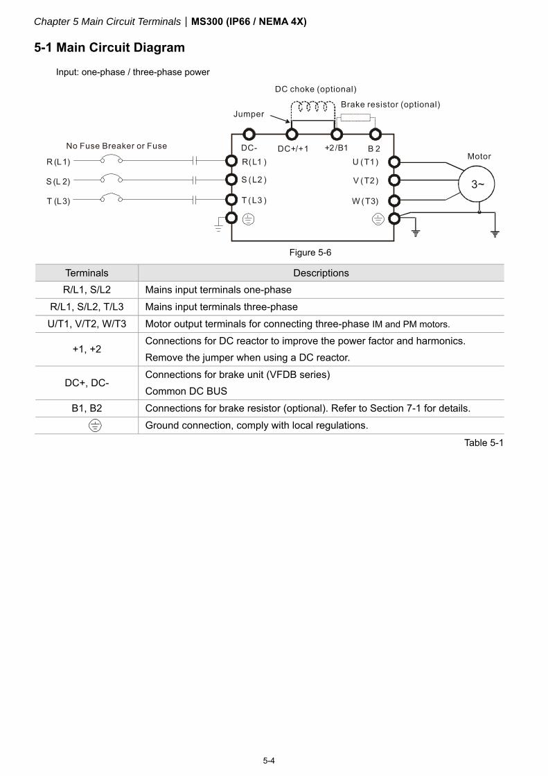
Input: one-phase / three-phase power
Terminals Descriptions R/L1, S/L2 Mains input terminals one-phase
R/L1, S/L2, T/L3 Mains input terminals three-phase U/T1, V/T2, W/T3 Motor output terminals for connecting three-phase IM and PM motors.
+1, +2 Connections for DC reactor to improve the power factor and harmonics. Remove the jumper when using a DC reactor.
DC+, DC- Connections for brake unit (VFDB series) Common DC BUS
B1, B2 Connections for brake resistor (optional). Refer to Section 7-1 for details.
Ground connection, comply with local regulations.
Table 5-1
Figure 5-6
Chapter 5 Main Circuit TerminalsMS300 (IP66 / NEMA 4X)
5-5
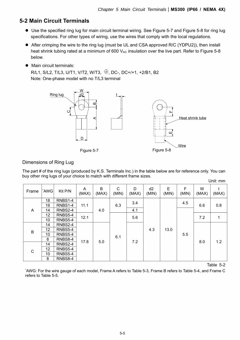
5-2 Main Circuit Terminals
Use the specified ring lug for main circuit terminal wiring. See Figure 5-7 and Figure 5-8 for ring lug specifications. For other types of wiring, use the wires that comply with the local regulations.
After crimping the wire to the ring lug (must be UL and CSA approved R/C (YDPU2)), then install heat shrink tubing rated at a minimum of 600 VAC insulation over the live part. Refer to Figure 5-8 below.
Main circuit terminals: R/L1, S/L2, T/L3, U/T1, V/T2, W/T3, , DC-, DC+/+1, +2/B1, B2 Note: One-phase model with no T/L3 terminal
Dimensions of Ring Lug
The part # of the ring lugs (produced by K.S. Terminals Inc.) in the table below are for reference only. You can buy other ring lugs of your choice to match with different frame sizes.
Unit: mm
Table 5-2 *AWG: For the wire gauge of each model, Frame A refers to Table 5-3, Frame B refers to Table 5-4, and Frame C refers to Table 5-5.
Frame *AWG Kit P/N A (MAX)
B (MAX)
C (MIN)
D (MAX)
d2 (MIN)
E (MIN)
F (MIN)
W (MAX)
t (MAX)
A
18 RNBS1-4 11.1
4.0 6.3 3.4
4.3 13.0
4.5 6.6 0.8 16 RNBS1-4 14 RNBS2-4 4.1
5.5
12 RNBS5-4 12.1
6.1
5.6 7.2 1 10 RNBS5-4
B
14 RNBS2-4
17.8 5.0 7.2 8.0 1.2
12 RNBS5-4 10 RNBS5-4 8 RNBS8-4
C
14 RNBS2-4 12 RNBS5-4 10 RNBS5-4 8 RNBS8-4
Figure 5-7 Figure 5-8
Chapter 5 Main Circuit TerminalsMS300 (IP66 / NEMA 4X)
5-6
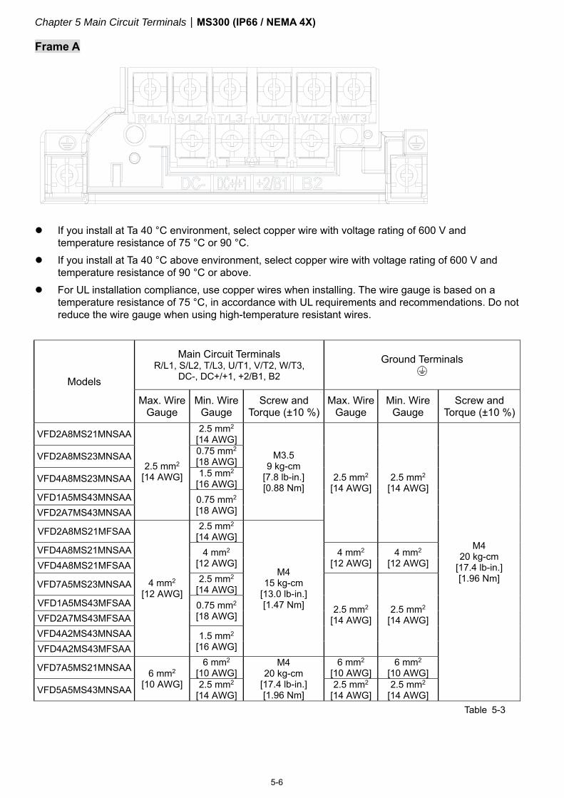
Frame A
If you install at Ta 40 °C environment, select copper wire with voltage rating of 600 V and
temperature resistance of 75 °C or 90 °C. If you install at Ta 40 °C above environment, select copper wire with voltage rating of 600 V and
temperature resistance of 90 °C or above. For UL installation compliance, use copper wires when installing. The wire gauge is based on a
temperature resistance of 75 °C, in accordance with UL requirements and recommendations. Do not reduce the wire gauge when using high-temperature resistant wires.
Models
Main Circuit Terminals R/L1, S/L2, T/L3, U/T1, V/T2, W/T3,
DC-, DC+/+1, +2/B1, B2 Ground Terminals
Max. Wire Gauge
Min. Wire Gauge
Screw and Torque (±10 %)
Max. Wire Gauge
Min. Wire Gauge
Screw and Torque (±10 %)
VFD2A8MS21MNSAA
2.5 mm2 [14 AWG]
2.5 mm2 [14 AWG]
M3.5 9 kg-cm
[7.8 lb-in.] [0.88 Nm]
2.5 mm2 [14 AWG]
2.5 mm2 [14 AWG]
M4 20 kg-cm
[17.4 lb-in.] [1.96 Nm]
VFD2A8MS23MNSAA 0.75 mm2 [18 AWG]
VFD4A8MS23MNSAA 1.5 mm2 [16 AWG]
VFD1A5MS43MNSAA 0.75 mm2 [18 AWG] VFD2A7MS43MNSAA
VFD2A8MS21MFSAA
4 mm2 [12 AWG]
2.5 mm2 [14 AWG]
M4 15 kg-cm
[13.0 lb-in.] [1.47 Nm]
VFD4A8MS21MNSAA 4 mm2 [12 AWG]
4 mm2 [12 AWG]
4 mm2 [12 AWG] VFD4A8MS21MFSAA
VFD7A5MS23MNSAA 2.5 mm2 [14 AWG]
2.5 mm2 [14 AWG]
2.5 mm2 [14 AWG]
VFD1A5MS43MFSAA 0.75 mm2 [18 AWG] VFD2A7MS43MFSAA
VFD4A2MS43MNSAA 1.5 mm2 [16 AWG] VFD4A2MS43MFSAA
VFD7A5MS21MNSAA 6 mm2 [10 AWG]
6 mm2 [10 AWG]
M4 20 kg-cm
[17.4 lb-in.] [1.96 Nm]
6 mm2 [10 AWG]
6 mm2 [10 AWG]
VFD5A5MS43MNSAA 2.5 mm2 [14 AWG]
2.5 mm2 [14 AWG]
2.5 mm2 [14 AWG]
Table 5-3
Chapter 5 Main Circuit TerminalsMS300 (IP66 / NEMA 4X)
5-7
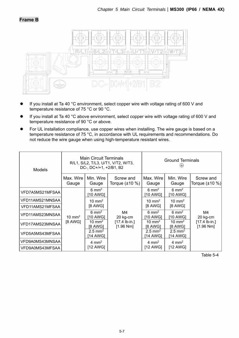
Frame B
If you install at Ta 40 °C environment, select copper wire with voltage rating of 600 V and
temperature resistance of 75 °C or 90 °C. If you install at Ta 40 °C above environment, select copper wire with voltage rating of 600 V and
temperature resistance of 90 °C or above. For UL installation compliance, use copper wires when installing. The wire gauge is based on a
temperature resistance of 75 °C, in accordance with UL requirements and recommendations. Do not reduce the wire gauge when using high-temperature resistant wires.
Models
Main Circuit Terminals R/L1, S/L2, T/L3, U/T1, V/T2, W/T3,
DC-, DC+/+1, +2/B1, B2
Ground Terminals
Max. Wire Gauge
Min. Wire Gauge
Screw and Torque (±10 %)
Max. Wire Gauge
Min. Wire Gauge
Screw and Torque (±10 %)
VFD7A5MS21MFSAA
10 mm2 [8 AWG]
6 mm2 [10 AWG]
M4 20 kg-cm
[17.4 lb-in.] [1.96 Nm]
6 mm2 [10 AWG]
6 mm2 [10 AWG]
M4 20 kg-cm
[17.4 lb-in.] [1.96 Nm]
VFD11AMS21MNSAA 10 mm2 [8 AWG]
10 mm2 [8 AWG]
10 mm2 [8 AWG] VFD11AMS21MFSAA
VFD11AMS23MNSAA 6 mm2 [10 AWG]
6 mm2 [10 AWG]
6 mm2 [10 AWG]
VFD17AMS23MNSAA 10 mm2 [8 AWG]
10 mm2 [8 AWG]
10 mm2 [8 AWG]
VFD5A5MS43MFSAA 2.5 mm2 [14 AWG]
2.5 mm2 [14 AWG]
2.5 mm2 [14 AWG]
VFD9A0MS43MNSAA 4 mm2 [12 AWG]
4 mm2 [12 AWG]
4 mm2 [12 AWG] VFD9A0MS43MFSAA
Table 5-4
Chapter 5 Main Circuit TerminalsMS300 (IP66 / NEMA 4X)
5-8
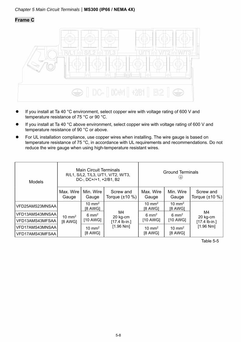
Frame C
If you install at Ta 40 °C environment, select copper wire with voltage rating of 600 V and
temperature resistance of 75 °C or 90 °C. If you install at Ta 40 °C above environment, select copper wire with voltage rating of 600 V and
temperature resistance of 90 °C or above. For UL installation compliance, use copper wires when installing. The wire gauge is based on
temperature resistance of 75 °C, in accordance with UL requirements and recommendations. Do not reduce the wire gauge when using high-temperature resistant wires.
Models
Main Circuit Terminals R/L1, S/L2, T/L3, U/T1, V/T2, W/T3,
DC-, DC+/+1, +2/B1, B2
Ground Terminals
Max. Wire Gauge
Min. Wire Gauge
Screw and Torque (±10 %)
Max. Wire Gauge
Min. Wire Gauge
Screw and Torque (±10 %)
VFD25AMS23MNSAA
10 mm2 [8 AWG]
10 mm2 [8 AWG]
M4 20 kg-cm
[17.4 lb-in.] [1.96 Nm]
10 mm2 [8 AWG]
10 mm2 [8 AWG]
M4 20 kg-cm
[17.4 lb-in.] [1.96 Nm]
VFD13AMS43MNSAA 6 mm2 [10 AWG]
6 mm2 [10 AWG]
6 mm2 [10 AWG] VFD13AMS43MFSAA
VFD17AMS43MNSAA 10 mm2 [8 AWG]
10 mm2 [8 AWG]
10 mm2 [8 AWG] VFD17AMS43MFSAA
Table 5-5

Chapter 6 Control Circuit Terminals MS300 (IP66 / NEMA 4X)
6-1
Chapter 6 Control Circuit Terminals
6-1 Control Circuit Terminal Specifications
Chapter 6 Control Circuit Terminals MS300 (IP66 / NEMA 4X)
6-2
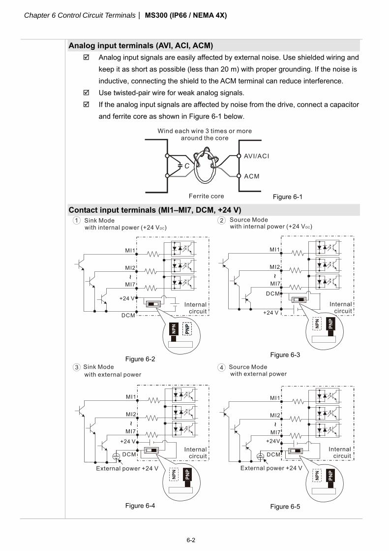
Analog input terminals (AVI, ACI, ACM)
Analog input signals are easily affected by external noise. Use shielded wiring and keep it as short as possible (less than 20 m) with proper grounding. If the noise is inductive, connecting the shield to the ACM terminal can reduce interference.
Use twisted-pair wire for weak analog signals. If the analog input signals are affected by noise from the drive, connect a capacitor
and ferrite core as shown in Figure 6-1 below.
Figure 6-1
Contact input terminals (MI1–MI7, DCM, +24 V)
Figure 6-2
Figure 6-3
Figure 6-4
Figure 6-5

Chapter 6 Control Circuit Terminals MS300 (IP66 / NEMA 4X)
6-3
When the photo coupler is using the internal power supply, the switch connection
for Sink and Source modes are as shown in Figure 6-2 and Figure 6-3 above: MI-DCM: Sink mode, MI-+24V: Source mode.
Transistor output terminals (MO1, MO2, MCM)
Make sure to connect the digital outputs to the correct polarity. See the wiring diagram when connecting a relay to the digital output, connect a surge absorber across the coil, and check the polarity.
Chapter 6 Control Circuit Terminals MS300 (IP66 / NEMA 4X)
6-4
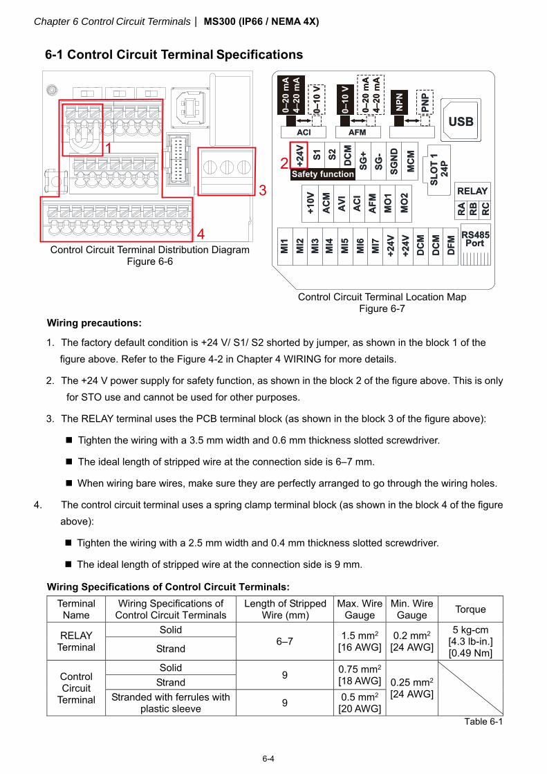
6-1 Control Circuit Terminal Specifications
Control Circuit Terminal Distribution Diagram Figure 6-6
Control Circuit Terminal Location Map
Figure 6-7 Wiring precautions:
1. The factory default condition is +24 V/ S1/ S2 shorted by jumper, as shown in the block 1 of the figure above. Refer to the Figure 4-2 in Chapter 4 WIRING for more details.
2. The +24 V power supply for safety function, as shown in the block 2 of the figure above. This is only for STO use and cannot be used for other purposes.
3. The RELAY terminal uses the PCB terminal block (as shown in the block 3 of the figure above):
Tighten the wiring with a 3.5 mm width and 0.6 mm thickness slotted screwdriver.
The ideal length of stripped wire at the connection side is 6–7 mm.
When wiring bare wires, make sure they are perfectly arranged to go through the wiring holes.
4. The control circuit terminal uses a spring clamp terminal block (as shown in the block 4 of the figure above):
Tighten the wiring with a 2.5 mm width and 0.4 mm thickness slotted screwdriver.
The ideal length of stripped wire at the connection side is 9 mm.
Wiring Specifications of Control Circuit Terminals:
Terminal Name
Wiring Specifications of Control Circuit Terminals
Length of Stripped Wire (mm)
Max. Wire Gauge
Min. Wire Gauge Torque
RELAY Terminal
Solid 6–7 1.5 mm2
[16 AWG] 0.2 mm2
[24 AWG]
5 kg-cm [4.3 lb-in.] [0.49 Nm] Strand
Control Circuit
Terminal
Solid 9 0.75 mm2
[18 AWG] 0.25 mm2 [24 AWG] Strand
Stranded with ferrules with plastic sleeve 9 0.5 mm2
[20 AWG] Table 6-1
Chapter 6 Control Circuit Terminals MS300 (IP66 / NEMA 4X)
6-5
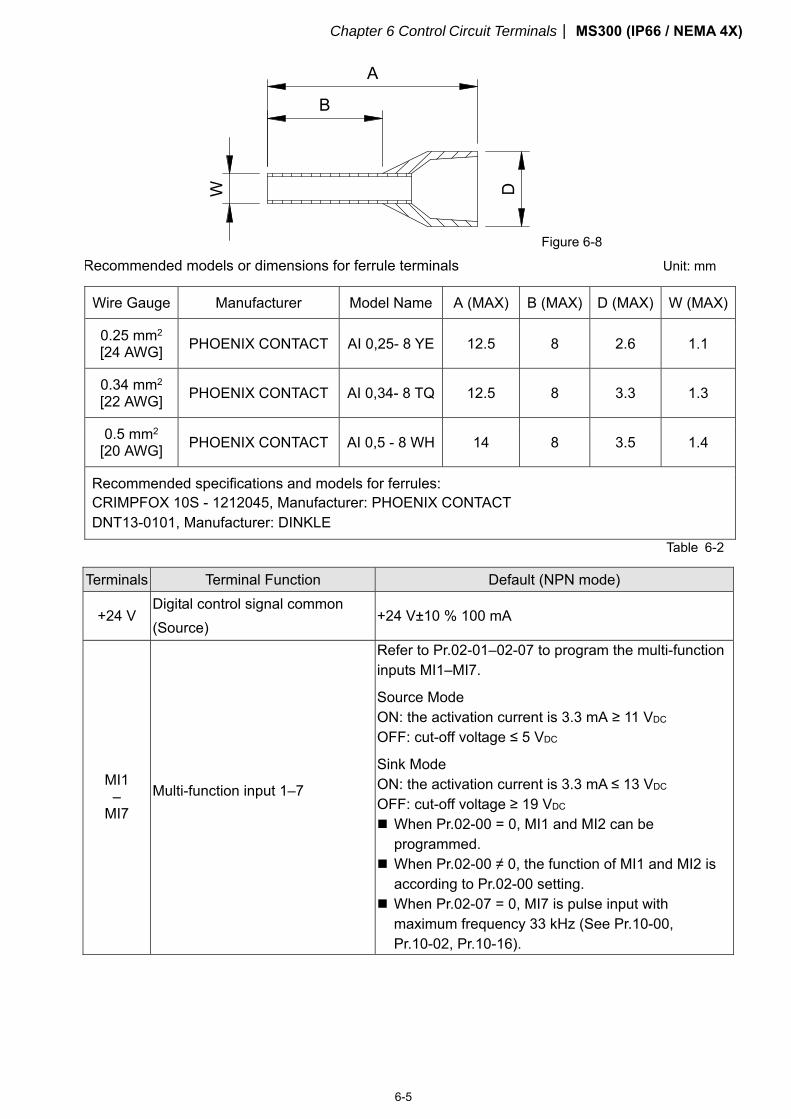
Figure 6-8
Recommended models or dimensions for ferrule terminals Unit: mm
Wire Gauge Manufacturer Model Name A (MAX) B (MAX) D (MAX) W (MAX)
0.25 mm2 [24 AWG] PHOENIX CONTACT AI 0,25- 8 YE 12.5 8 2.6 1.1
0.34 mm2 [22 AWG] PHOENIX CONTACT AI 0,34- 8 TQ 12.5 8 3.3 1.3
0.5 mm2 [20 AWG] PHOENIX CONTACT AI 0,5 - 8 WH 14 8 3.5 1.4
Recommended specifications and models for ferrules: CRIMPFOX 10S - 1212045, Manufacturer: PHOENIX CONTACT DNT13-0101, Manufacturer: DINKLE
Table 6-2
Terminals Terminal Function Default (NPN mode)
+24 V Digital control signal common (Source)
+24 V±10 % 100 mA
MI1 –
MI7 Multi-function input 1–7
Refer to Pr.02-01–02-07 to program the multi-function inputs MI1–MI7.
Source Mode ON: the activation current is 3.3 mA ≥ 11 VDC OFF: cut-off voltage ≤ 5 VDC
Sink Mode ON: the activation current is 3.3 mA ≤ 13 VDC OFF: cut-off voltage ≥ 19 VDC When Pr.02-00 = 0, MI1 and MI2 can be
programmed. When Pr.02-00 ≠ 0, the function of MI1 and MI2 is
according to Pr.02-00 setting. When Pr.02-07 = 0, MI7 is pulse input with
maximum frequency 33 kHz (See Pr.10-00, Pr.10-02, Pr.10-16).
Chapter 6 Control Circuit Terminals MS300 (IP66 / NEMA 4X)
6-6
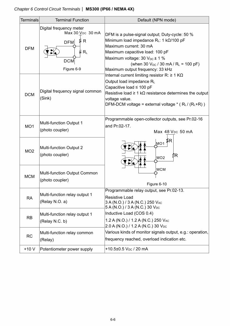
Terminals Terminal Function Default (NPN mode)
DFM
Digital frequency meter
Figure 6-9
DFM is a pulse-signal output; Duty-cycle: 50 % Minimum load impedance RL: 1 kΩ/100 pF Maximum current: 30 mA Maximum capacitive load: 100 pF Maximum voltage: 30 VDC ± 1 %
(when 30 VDC / 30 mA / RL = 100 pF) Maximum output frequency: 33 kHz Internal current limiting resistor R: ≥ 1 KΩ Output load impedance RL Capacitive load ≤ 100 pF Resistive load ≥ 1 kΩ resistance determines the output voltage value. DFM-DCM voltage = external voltage * ( RL / (RL+R) )
DCM Digital frequency signal common (Sink)
MO1 Multi-function Output 1 (photo coupler)
Programmable open-collector outputs, see Pr.02-16 and Pr.02-17.
Figure 6-10
MO2 Multi-function Output 2 (photo coupler)
MCM Multi-function Output Common (photo coupler)
RA Multi-function relay output 1 (Relay N.O. a)
Programmable relay output, see Pr.02-13. Resistive Load 3 A (N.O.) / 3 A (N.C.) 250 VAC 5 A (N.O.) / 3 A (N.C.) 30 VDC Inductive Load (COS 0.4) 1.2 A (N.O.) / 1.2 A (N.C.) 250 VAC 2.0 A (N.O.) / 1.2 A (N.C.) 30 VDC Various kinds of monitor signals output, e.g.: operation, frequency reached, overload indication etc.
RB Multi-function relay output 1 (Relay N.C. b)
RC Multi-function relay common (Relay)
+10 V Potentiometer power supply +10.5±0.5 VDC / 20 mA
Chapter 6 Control Circuit Terminals MS300 (IP66 / NEMA 4X)
6-7
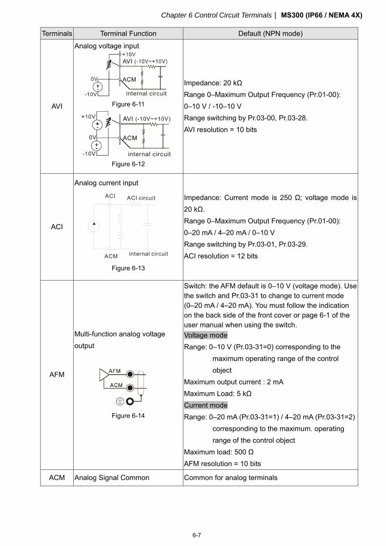
Terminals Terminal Function Default (NPN mode)
AVI
Analog voltage input
internal circuit Figure 6-11
internal circuit Figure 6-12
Impedance: 20 kΩ Range 0–Maximum Output Frequency (Pr.01-00): 0–10 V / -10–10 V Range switching by Pr.03-00, Pr.03-28. AVI resolution = 10 bits
ACI
Analog current input
ACM
ACI ACI circuit
internal circuit
Figure 6-13
Impedance: Current mode is 250 Ω; voltage mode is 20 kΩ. Range 0–Maximum Output Frequency (Pr.01-00): 0–20 mA / 4–20 mA / 0–10 V Range switching by Pr.03-01, Pr.03-29. ACI resolution = 12 bits
AFM
Multi-function analog voltage output
Figure 6-14
Switch: the AFM default is 0–10 V (voltage mode). Use the switch and Pr.03-31 to change to current mode (0–20 mA / 4–20 mA). You must follow the indication on the back side of the front cover or page 6-1 of the user manual when using the switch. Voltage mode Range: 0–10 V (Pr.03-31=0) corresponding to the
maximum operating range of the control object
Maximum output current : 2 mA Maximum Load: 5 kΩ Current mode Range: 0–20 mA (Pr.03-31=1) / 4–20 mA (Pr.03-31=2)
corresponding to the maximum. operating range of the control object
Maximum load: 500 Ω AFM resolution = 10 bits
ACM Analog Signal Common Common for analog terminals
Chapter 6 Control Circuit Terminals MS300 (IP66 / NEMA 4X)
6-8
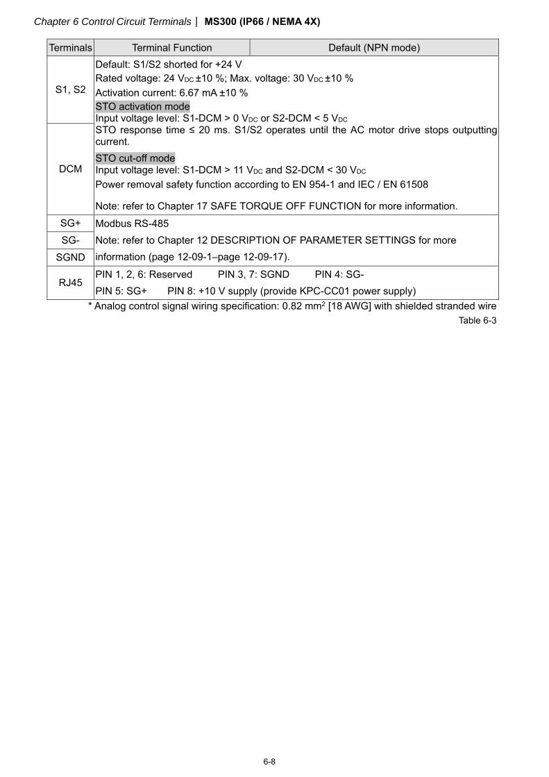
Terminals Terminal Function Default (NPN mode)
S1, S2
Default: S1/S2 shorted for +24 V Rated voltage: 24 VDC ±10 %; Max. voltage: 30 VDC ±10 % Activation current: 6.67 mA ±10 % STO activation mode Input voltage level: S1-DCM > 0 VDC or S2-DCM < 5 VDC STO response time ≤ 20 ms. S1/S2 operates until the AC motor drive stops outputting current. STO cut-off mode Input voltage level: S1-DCM > 11 VDC and S2-DCM < 30 VDC Power removal safety function according to EN 954-1 and IEC / EN 61508
Note: refer to Chapter 17 SAFE TORQUE OFF FUNCTION for more information.
DCM
SG+ Modbus RS-485 Note: refer to Chapter 12 DESCRIPTION OF PARAMETER SETTINGS for more information (page 12-09-1–page 12-09-17).
SG- SGND
RJ45 PIN 1, 2, 6: Reserved PIN 3, 7: SGND PIN 4: SG- PIN 5: SG+ PIN 8: +10 V supply (provide KPC-CC01 power supply)
* Analog control signal wiring specification: 0.82 mm2 [18 AWG] with shielded stranded wire Table 6-3
Chapter 7 Optional Accessories MS300 (IP66 / NEMA 4X)
7-1
Chapter 7 Optional Accessories
7-1 All Brake Resistors and Brake Units Used in AC Motor Drives
7-2 Non-fuse Circuit Breaker
7-3 Fuse Specification Table
7-4 AC/DC Reactor
7-5 Zero Phase Reactors
7-6 EMC Filter
7-7 EMC Shield Plate
7-8 Capacitive Filter
7-9 Fan Kit
7-10 Main Switch
Chapter 7 Optional Accessories MS300 (IP66 / NEMA 4X)
7-2
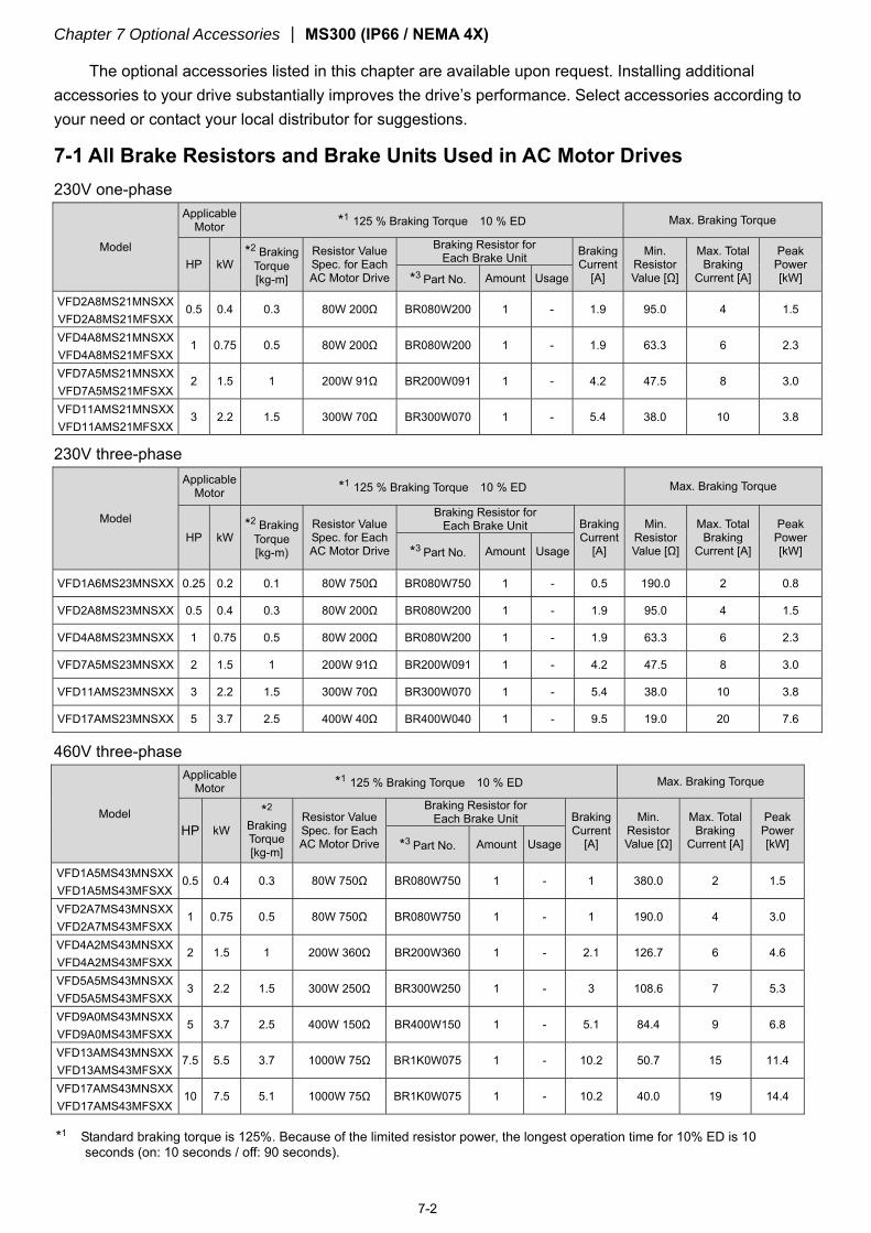
The optional accessories listed in this chapter are available upon request. Installing additional accessories to your drive substantially improves the drive’s performance. Select accessories according to your need or contact your local distributor for suggestions.
7-1 All Brake Resistors and Brake Units Used in AC Motor Drives 230V one-phase
Model
Applicable Motor *1 125 % Braking Torque 10 % ED Max. Braking Torque
HP kW *2 Braking
Torque [kg-m]
Resistor Value Spec. for Each AC Motor Drive
Braking Resistor for Each Brake Unit Braking
Current [A]
Min. Resistor Value [Ω]
Max. Total Braking
Current [A]
Peak Power [kW] *3 Part No. Amount Usage
VFD2A8MS21MNSXX VFD2A8MS21MFSXX
0.5 0.4 0.3 80W 200Ω BR080W200 1 - 1.9 95.0 4 1.5
VFD4A8MS21MNSXX VFD4A8MS21MFSXX
1 0.75 0.5 80W 200Ω BR080W200 1 - 1.9 63.3 6 2.3
VFD7A5MS21MNSXX VFD7A5MS21MFSXX
2 1.5 1 200W 91Ω BR200W091 1 - 4.2 47.5 8 3.0
VFD11AMS21MNSXX VFD11AMS21MFSXX
3 2.2 1.5 300W 70Ω BR300W070 1 - 5.4 38.0 10 3.8
230V three-phase
Model
Applicable Motor *1 125 % Braking Torque 10 % ED Max. Braking Torque
HP kW *2 Braking
Torque [kg-m)
Resistor Value Spec. for Each AC Motor Drive
Braking Resistor for Each Brake Unit Braking
Current [A]
Min. Resistor Value [Ω]
Max. Total Braking
Current [A]
Peak Power [kW] *3 Part No. Amount Usage
VFD1A6MS23MNSXX 0.25 0.2 0.1 80W 750Ω BR080W750 1 - 0.5 190.0 2 0.8
VFD2A8MS23MNSXX 0.5 0.4 0.3 80W 200Ω BR080W200 1 - 1.9 95.0 4 1.5
VFD4A8MS23MNSXX 1 0.75 0.5 80W 200Ω BR080W200 1 - 1.9 63.3 6 2.3
VFD7A5MS23MNSXX 2 1.5 1 200W 91Ω BR200W091 1 - 4.2 47.5 8 3.0
VFD11AMS23MNSXX 3 2.2 1.5 300W 70Ω BR300W070 1 - 5.4 38.0 10 3.8
VFD17AMS23MNSXX 5 3.7 2.5 400W 40Ω BR400W040 1 - 9.5 19.0 20 7.6
460V three-phase
Model
Applicable Motor *1 125 % Braking Torque 10 % ED Max. Braking Torque
HP kW *2
Braking Torque [kg-m]
Resistor Value Spec. for Each AC Motor Drive
Braking Resistor for Each Brake Unit Braking
Current [A]
Min. Resistor Value [Ω]
Max. Total Braking
Current [A]
Peak Power [kW] *3 Part No. Amount Usage
VFD1A5MS43MNSXX VFD1A5MS43MFSXX
0.5 0.4 0.3 80W 750Ω BR080W750 1 - 1 380.0 2 1.5
VFD2A7MS43MNSXX VFD2A7MS43MFSXX
1 0.75 0.5 80W 750Ω BR080W750 1 - 1 190.0 4 3.0
VFD4A2MS43MNSXX VFD4A2MS43MFSXX
2 1.5 1 200W 360Ω BR200W360 1 - 2.1 126.7 6 4.6
VFD5A5MS43MNSXX VFD5A5MS43MFSXX
3 2.2 1.5 300W 250Ω BR300W250 1 - 3 108.6 7 5.3
VFD9A0MS43MNSXX VFD9A0MS43MFSXX
5 3.7 2.5 400W 150Ω BR400W150 1 - 5.1 84.4 9 6.8
VFD13AMS43MNSXX VFD13AMS43MFSXX
7.5 5.5 3.7 1000W 75Ω BR1K0W075 1 - 10.2 50.7 15 11.4
VFD17AMS43MNSXX VFD17AMS43MFSXX
10 7.5 5.1 1000W 75Ω BR1K0W075 1 - 10.2 40.0 19 14.4
*1 Standard braking torque is 125%. Because of the limited resistor power, the longest operation time for 10% ED is 10 seconds (on: 10 seconds / off: 90 seconds).
Chapter 7 Optional Accessories MS300 (IP66 / NEMA 4X)
7-3
*2 Calculation for braking torque is for a four-pole motor 1800 rpm. *3 Resistors of 400 W or lower should be fixed to the frame and at a surface temperature below 250°C (400°C).
Resistors of 1000 W and above should be fixed on a surface with temperature below 600°C (If the temperature is higher than the resistance temperature limit, install a heat dissipation system or increase the resistance power.).
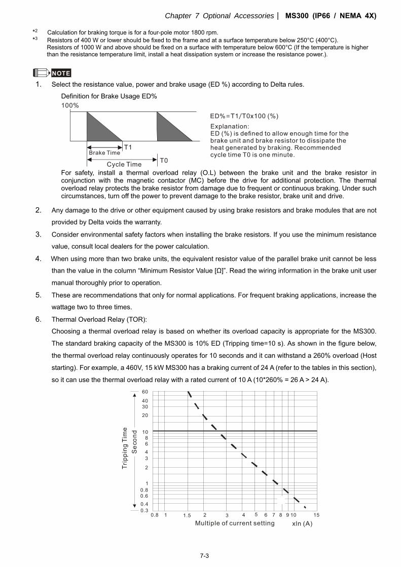
NOTE 1. Select the resistance value, power and brake usage (ED %) according to Delta rules.
Definition for Brake Usage ED%
For safety, install a thermal overload relay (O.L) between the brake unit and the brake resistor in conjunction with the magnetic contactor (MC) before the drive for additional protection. The thermal overload relay protects the brake resistor from damage due to frequent or continuous braking. Under such circumstances, turn off the power to prevent damage to the brake resistor, brake unit and drive.
2. Any damage to the drive or other equipment caused by using brake resistors and brake modules that are not
provided by Delta voids the warranty.
3. Consider environmental safety factors when installing the brake resistors. If you use the minimum resistance
value, consult local dealers for the power calculation.
4. When using more than two brake units, the equivalent resistor value of the parallel brake unit cannot be less
than the value in the column “Minimum Resistor Value [Ω]”. Read the wiring information in the brake unit user
manual thoroughly prior to operation.
5. These are recommendations that only for normal applications. For frequent braking applications, increase the
wattage two to three times.
6. Thermal Overload Relay (TOR):
Choosing a thermal overload relay is based on whether its overload capacity is appropriate for the MS300.
The standard braking capacity of the MS300 is 10% ED (Tripping time=10 s). As shown in the figure below,
the thermal overload relay continuously operates for 10 seconds and it can withstand a 260% overload (Host
starting). For example, a 460V, 15 kW MS300 has a braking current of 24 A (refer to the tables in this section),
so it can use the thermal overload relay with a rated current of 10 A (10*260% = 26 A > 24 A).
Chapter 7 Optional Accessories MS300 (IP66 / NEMA 4X)
7-4
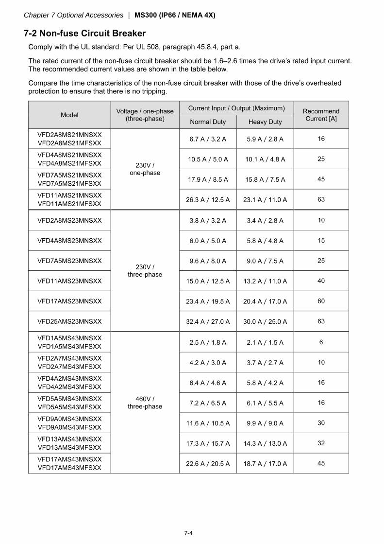
7-2 Non-fuse Circuit Breaker
Comply with the UL standard: Per UL 508, paragraph 45.8.4, part a.
The rated current of the non-fuse circuit breaker should be 1.6–2.6 times the drive’s rated input current. The recommended current values are shown in the table below.
Compare the time characteristics of the non-fuse circuit breaker with those of the drive’s overheated protection to ensure that there is no tripping.
Model Voltage / one-phase (three-phase)
Current Input / Output (Maximum) Recommend Current [A] Normal Duty Heavy Duty
VFD2A8MS21MNSXX VFD2A8MS21MFSXX
230V / one-phase
6.7 A/3.2 A 5.9 A/2.8 A 16
VFD4A8MS21MNSXX VFD4A8MS21MFSXX 10.5 A/5.0 A 10.1 A/4.8 A 25
VFD7A5MS21MNSXX VFD7A5MS21MFSXX 17.9 A/8.5 A 15.8 A/7.5 A 45
VFD11AMS21MNSXX VFD11AMS21MFSXX 26.3 A/12.5 A 23.1 A/11.0 A 63
VFD2A8MS23MNSXX
230V / three-phase
3.8 A/3.2 A 3.4 A/2.8 A 10
VFD4A8MS23MNSXX 6.0 A/5.0 A 5.8 A/4.8 A 15
VFD7A5MS23MNSXX 9.6 A/8.0 A 9.0 A/7.5 A 25
VFD11AMS23MNSXX 15.0 A/12.5 A 13.2 A/11.0 A 40
VFD17AMS23MNSXX 23.4 A/19.5 A 20.4 A/17.0 A 60
VFD25AMS23MNSXX 32.4 A/27.0 A 30.0 A/25.0 A 63
VFD1A5MS43MNSXX VFD1A5MS43MFSXX
460V / three-phase
2.5 A/1.8 A 2.1 A/1.5 A 6
VFD2A7MS43MNSXX VFD2A7MS43MFSXX 4.2 A/3.0 A 3.7 A/2.7 A 10
VFD4A2MS43MNSXX VFD4A2MS43MFSXX 6.4 A/4.6 A 5.8 A/4.2 A 16
VFD5A5MS43MNSXX VFD5A5MS43MFSXX 7.2 A/6.5 A 6.1 A/5.5 A 16
VFD9A0MS43MNSXX VFD9A0MS43MFSXX 11.6 A/10.5 A 9.9 A/9.0 A 30
VFD13AMS43MNSXX VFD13AMS43MFSXX 17.3 A/15.7 A 14.3 A/13.0 A 32
VFD17AMS43MNSXX VFD17AMS43MFSXX 22.6 A/20.5 A 18.7 A/17.0 A 45
Chapter 7 Optional Accessories MS300 (IP66 / NEMA 4X)
7-5
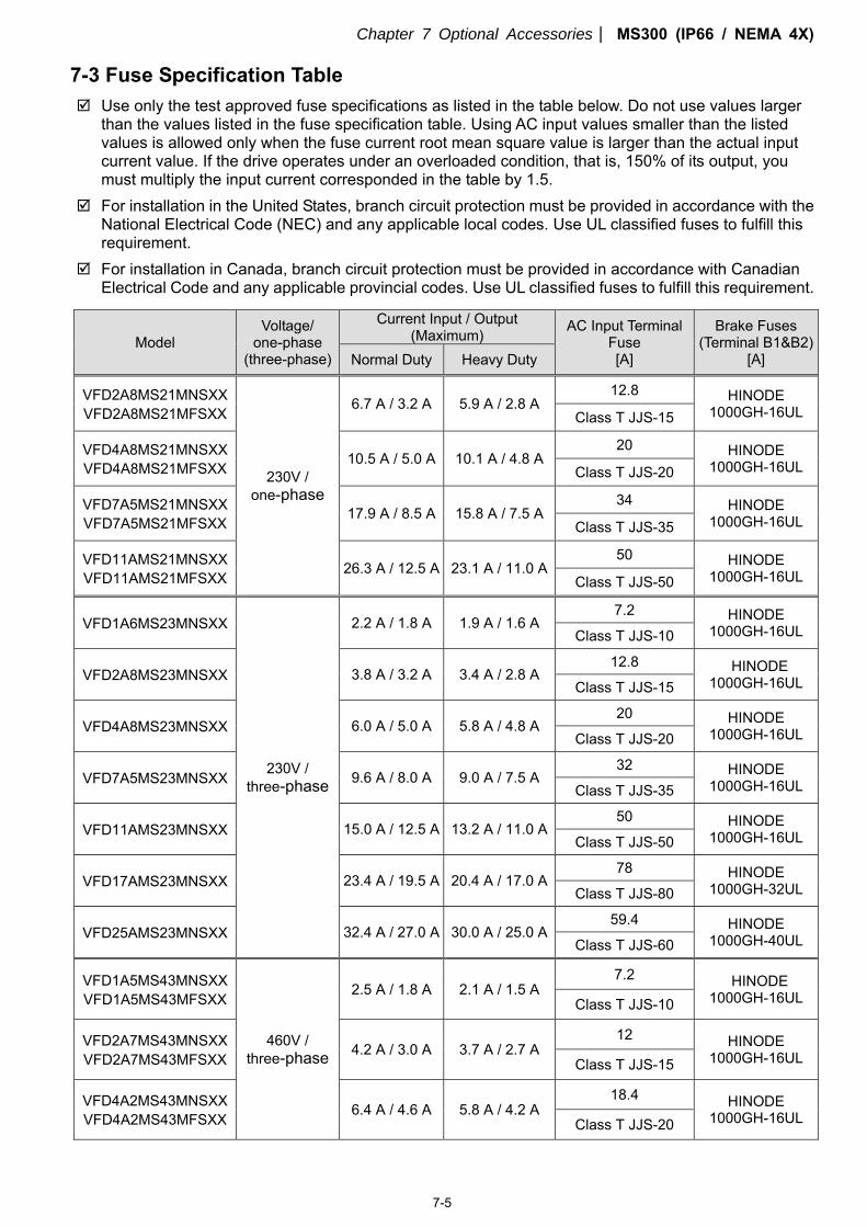
7-3 Fuse Specification Table
Use only the test approved fuse specifications as listed in the table below. Do not use values larger than the values listed in the fuse specification table. Using AC input values smaller than the listed values is allowed only when the fuse current root mean square value is larger than the actual input current value. If the drive operates under an overloaded condition, that is, 150% of its output, you must multiply the input current corresponded in the table by 1.5.
For installation in the United States, branch circuit protection must be provided in accordance with the National Electrical Code (NEC) and any applicable local codes. Use UL classified fuses to fulfill this requirement.
For installation in Canada, branch circuit protection must be provided in accordance with Canadian Electrical Code and any applicable provincial codes. Use UL classified fuses to fulfill this requirement.
Model Voltage/
one-phase (three-phase)
Current Input / Output (Maximum) AC Input Terminal
Fuse [A]
Brake Fuses (Terminal B1&B2)
[A] Normal Duty Heavy Duty
VFD2A8MS21MNSXX VFD2A8MS21MFSXX
230V / one-phase
6.7 A / 3.2 A 5.9 A / 2.8 A 12.8 HINODE
1000GH-16UL Class T JJS-15
VFD4A8MS21MNSXX VFD4A8MS21MFSXX
10.5 A / 5.0 A 10.1 A / 4.8 A 20 HINODE
1000GH-16UL Class T JJS-20
VFD7A5MS21MNSXX VFD7A5MS21MFSXX
17.9 A / 8.5 A 15.8 A / 7.5 A 34 HINODE
1000GH-16UL Class T JJS-35
VFD11AMS21MNSXX VFD11AMS21MFSXX
26.3 A / 12.5 A 23.1 A / 11.0 A 50 HINODE
1000GH-16UL Class T JJS-50
VFD1A6MS23MNSXX
230V / three-phase
2.2 A / 1.8 A 1.9 A / 1.6 A 7.2 HINODE
1000GH-16UL Class T JJS-10
VFD2A8MS23MNSXX 3.8 A / 3.2 A 3.4 A / 2.8 A 12.8 HINODE
1000GH-16UL Class T JJS-15
VFD4A8MS23MNSXX 6.0 A / 5.0 A 5.8 A / 4.8 A 20 HINODE
1000GH-16UL Class T JJS-20
VFD7A5MS23MNSXX 9.6 A / 8.0 A 9.0 A / 7.5 A 32 HINODE
1000GH-16UL Class T JJS-35
VFD11AMS23MNSXX 15.0 A / 12.5 A 13.2 A / 11.0 A 50 HINODE
1000GH-16UL Class T JJS-50
VFD17AMS23MNSXX 23.4 A / 19.5 A 20.4 A / 17.0 A 78 HINODE
1000GH-32UL Class T JJS-80
VFD25AMS23MNSXX 32.4 A / 27.0 A 30.0 A / 25.0 A 59.4 HINODE
1000GH-40UL Class T JJS-60
VFD1A5MS43MNSXX VFD1A5MS43MFSXX
460V / three-phase
2.5 A / 1.8 A 2.1 A / 1.5 A 7.2 HINODE
1000GH-16UL Class T JJS-10
VFD2A7MS43MNSXX VFD2A7MS43MFSXX
4.2 A / 3.0 A 3.7 A / 2.7 A 12 HINODE
1000GH-16UL Class T JJS-15
VFD4A2MS43MNSXX VFD4A2MS43MFSXX
6.4 A / 4.6 A 5.8 A / 4.2 A 18.4 HINODE
1000GH-16UL Class T JJS-20
Chapter 7 Optional Accessories MS300 (IP66 / NEMA 4X)
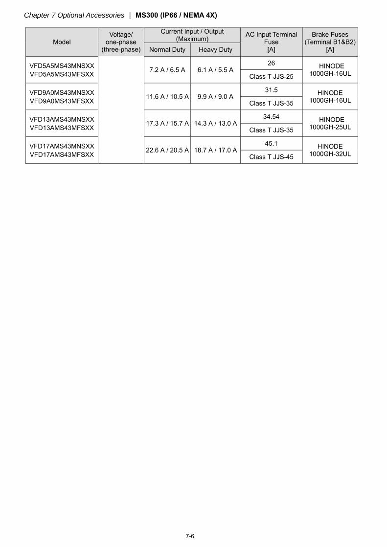
7-6
Model Voltage/
one-phase (three-phase)
Current Input / Output (Maximum) AC Input Terminal
Fuse [A]
Brake Fuses (Terminal B1&B2)
[A] Normal Duty Heavy Duty
VFD5A5MS43MNSXX VFD5A5MS43MFSXX
7.2 A / 6.5 A 6.1 A / 5.5 A 26 HINODE
1000GH-16UL Class T JJS-25
VFD9A0MS43MNSXX VFD9A0MS43MFSXX
11.6 A / 10.5 A 9.9 A / 9.0 A 31.5 HINODE
1000GH-16UL Class T JJS-35
VFD13AMS43MNSXX VFD13AMS43MFSXX
17.3 A / 15.7 A 14.3 A / 13.0 A 34.54 HINODE
1000GH-25UL Class T JJS-35
VFD17AMS43MNSXX VFD17AMS43MFSXX
22.6 A / 20.5 A 18.7 A / 17.0 A 45.1 HINODE
1000GH-32UL Class T JJS-45
Chapter 7 Optional Accessories MS300 (IP66 / NEMA 4X)
7-7
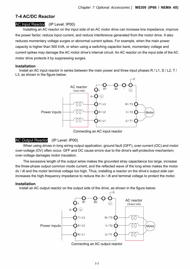
7-4 AC/DC Reactor
AC Input Reactor (IP Level: IP00) Installing an AC reactor on the input side of an AC motor drive can increase line impedance, improve
the power factor, reduce input current, and reduce interference generated from the motor drive. It also reduces momentary voltage surges or abnormal current spikes. For example, when the main power capacity is higher than 500 kVA, or when using a switching capacitor bank, momentary voltage and current spikes may damage the AC motor drive’s internal circuit. An AC reactor on the input side of the AC motor drive protects it by suppressing surges.
Installation Install an AC input reactor in series between the main power and three input phases R / L1, S / L2, T /
L3, as shown in the figure below:
Connecting an AC input reactor
AC Output Reactor (IP Level: IP00) When using drives in long wiring output application, ground fault (GFF), over-current (OC) and motor
over-voltage (OV) often occur. GFF and OC cause errors due to the drive's self-protective mechanism; over-voltage damages motor insulation.
The excessive length of the output wires makes the grounded stray capacitance too large, increase the three-phase output common mode current, and the reflected wave of the long wires makes the motor dv / dt and the motor terminal voltage too high. Thus, installing a reactor on the drive’s output side can increases the high-frequency impedance to reduce the dv / dt and terminal voltage to protect the motor.
Installation Install an AC output reactor on the output side of the drive, as shown in the figure below:
Connecting an AC output reactor
Chapter 7 Optional Accessories MS300 (IP66 / NEMA 4X)
7-8
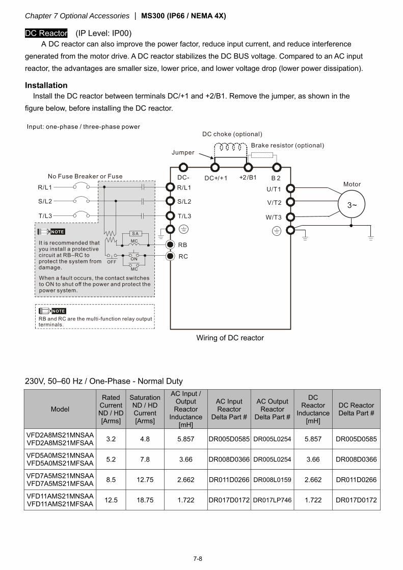
DC Reactor (IP Level: IP00) A DC reactor can also improve the power factor, reduce input current, and reduce interference
generated from the motor drive. A DC reactor stabilizes the DC BUS voltage. Compared to an AC input reactor, the advantages are smaller size, lower price, and lower voltage drop (lower power dissipation).
Installation Install the DC reactor between terminals DC/+1 and +2/B1. Remove the jumper, as shown in the
figure below, before installing the DC reactor.
Wiring of DC reactor
230V, 50–60 Hz / One-Phase - Normal Duty
Model
Rated Current ND / HD [Arms]
Saturation ND / HD Current [Arms]
AC Input / Output Reactor
Inductance [mH]
AC Input Reactor
Delta Part #
AC Output Reactor
Delta Part #
DC Reactor
Inductance [mH]
DC Reactor Delta Part #
VFD2A8MS21MNSAA VFD2A8MS21MFSAA 3.2 4.8 5.857 DR005D0585 DR005L0254 5.857 DR005D0585
VFD5A0MS21MNSAA VFD5A0MS21MFSAA 5.2 7.8 3.66 DR008D0366 DR005L0254 3.66 DR008D0366
VFD7A5MS21MNSAA VFD7A5MS21MFSAA 8.5 12.75 2.662 DR011D0266 DR008L0159 2.662 DR011D0266
VFD11AMS21MNSAA VFD11AMS21MFSAA 12.5 18.75 1.722 DR017D0172 DR017LP746 1.722 DR017D0172
Chapter 7 Optional Accessories MS300 (IP66 / NEMA 4X)
7-9
230V, 50–60 Hz / One-Phase - Heavy Duty
Model
Rated Current ND / HD [Arms]
Saturation ND / HD Current [Arms]
AC Input / Output Reactor
Inductance [mH]
AC Input Reactor
Delta Part #
AC Output Reactor
Delta Part #
DC Reactor
Inductance [mH]
DC Reactor Delta Part #
VFD2A8MS21MNSAA VFD2A8MS21MFSAA 2.8 5.6 5.857 DR005D0585 DR005L0254 5.857 DR005D0585
VFD4A8MS21MNSAA VFD4A8MS21MFSAA 4.8 9.6 3.66 DR008D0366 DR005L0254 3.66 DR008D0366
VFD7A5MS21MNSAA VFD7A5MS21MFSAA 7.5 15.0 2.662 DR011D0266 DR008L0159 2.662 DR011D0266
VFD11AMS21MNSAA VFD11AMS21MFSAA 11.0 22.0 1.722 DR017D0172 DR011L0115 1.722 DR017D0172
230V, 50–60 Hz / Three-Phase - Normal Duty
Model
Rated Current ND / HD [Arms]
Saturation ND / HD Current [Arms]
AC Input / Output Reactor
Inductance [mH]
AC Input Reactor
Delta Part #
AC Output Reactor
Delta Part #
DC Reactor
Inductance [mH]
DC Reactor Delta Part #
VFD2A8MS23MNSAA 3.2 4.8 2.536 DR005A0254 DR005L0254 5.857 DR005D0585
VFD4A8MS23MNSAA 5.0 7.5 2.536 DR005A0254 DR005L0254 5.857 DR005D0585
VFD7A5MS23MNSAA 8.0 12.0 1.585 DR008A0159 DR008L0159 3.66 DR008D0366
VFD11AMS23MNSAA 12.5 18.75 0.746 DR017AP746 DR017LP746 2.662 DR011D0266
VFD17AMS23MNSAA 19.5 29.25 0.507 DR025AP507 DR025LP507 1.722 DR017D0172
VFD25AMS23MNSAA 27.0 40.5 0.32 DR033AP320 DR033LP320 1.172 DR025D0117
230V, 50–60 Hz / Three-Phase - Heavy Duty
Model
Rated Current ND / HD [Arms]
Saturation ND / HD Current [Arms]
AC Input / Output Reactor
Inductance [mH]
AC Input Reactor
Delta Part #
AC Output Reactor
Delta Part #
DC Reactor
Inductance [mH]
DC Reactor Delta Part #
VFD2A8MS23MNSAA 2.8 5.6 2.536 DR005A0254 DR005L0254 5.857 DR005D0585
VFD4A8MS23MNSAA 4.8 9.6 2.536 DR005A0254 DR005L0254 5.857 DR005D0585
VFD7A5MS23MNSAA 7.5 15.0 1.585 DR008A0159 DR008L0159 3.66 DR008D0366
VFD11AMS23MNSAA 11.0 22.0 1.152 DR011A0115 DR011L0115 2.662 DR011D0266
VFD17AMS23MNSAA 17.0 34.0 0.746 DR017AP746 DR017LP746 1.722 DR017D0172
VFD25AMS23MNSAA 25.0 50.0 0.507 DR025AP507 DR025LP507 1.172 DR025D0117
Chapter 7 Optional Accessories MS300 (IP66 / NEMA 4X)
7-10
460V, 50–60 Hz / Three-Phase - Normal Duty
Model
Rated Current ND / HD [Arms]
Saturation ND / HD Current [Arms]
AC Input / Output Reactor
Inductance [mH]
AC Input Reactor
Delta Part #
AC Output Reactor
Delta Part #
DC Reactor Inductance
[mH]
DC Reactor Delta Part #
VFD1A5MS43MNSAA VFD1A5MS43MFSAA 1.8 2.7 8.102 DR003A0810 DR003L0810 18.709 DR003D1870
VFD2A7MS43MNSAA VFD2A7MS43MFSAA 3.0 4.5 6.077 DR004A0607 DR004L0607 18.709 DR003D1870
VFD4A2MS43MFSAA VFD4A2MS43MNSAA 4.6 6.9 4.05 DR006A0405 DR006L0405 14.031 DR004D1403
VFD5A5MS43MFSAA VFD5A5MS43MNSAA 6.5 9.75 2.7 DR009A0270 DR009L0270 9.355 DR006D0935
VFD9A0MS43MFSAA VFD9A0MS43MNSAA 10.5 15.75 2.315 DR010A0231 DR010L0231 5.345 DR010D0534
VFD13AMS43MFSAA VFD13AMS43MNSAA 15.7 23.55 1.174 DR018A0117 DR012L0202 3.119 DR018D0311
VFD17AMS43MFSAA VFD17AMS43MNSAA 20.5 30.75 0.881 DR024AP881 DR018L0117 3.119 DR018D0311
460V, 50–60 Hz / Three-Phase - Heavy Duty
Model
Rated Current ND / HD [Arms]
Saturation ND / HD Current [Arms]
AC Input / Output Reactor
Inductance [mH]
AC Input Reactor
Delta Part #
AC Output Reactor
Delta Part #
DC Reactor Inductance
[mH]
DC Reactor Delta Part #
VFD1A5MS43MNSAA VFD1A5MS43MFSAA 1.5 3.0 8.102 DR003A0810 DR003L0810 18.709 DR003D1870
VFD2A7MS43MNSAA VFD2A7MS43MFSAA 2.7 5.4 8.102 DR003A0810 DR003L0810 18.709 DR003D1870
VFD4A2MS43MFSAA VFD4A2MS43MNSAA 4.2 8.4 6.077 DR004A0607 DR004L0607 14.031 DR004D1403
VFD5A5MS43MNSAA VFD5A5MS43MFSAA 5.5 11.0 4.05 DR006A0405 DR006L0405 9.355 DR006D0935
VFD9A0MS43MNSAA VFD9A0MS43MFSAA 9.0 18.0 2.7 DR009A0270 DR009L0270 6.236 DR009D0623
VFD13AMS43MNSAA VFD13AMS43MFSAA 13.0 26.0 1.174 DR018A0117 DR010L0231 4.677 DR012D0467
VFD17AMS43MNSAA VFD17AMS43MFSAA 17.0 34.0 1.174 DR018A0117 DR012L0202 3.119 DR018D0311
Chapter 7 Optional Accessories MS300 (IP66 / NEMA 4X)
7-11
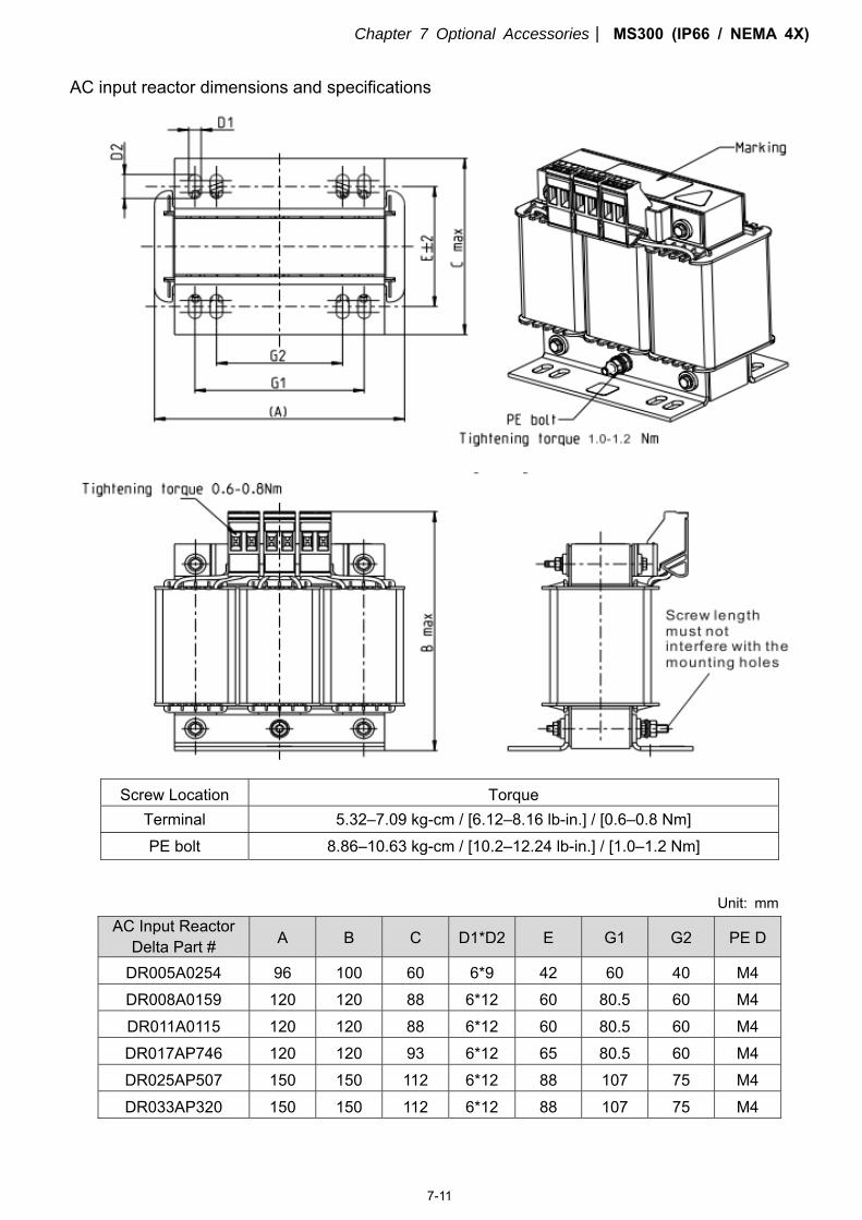
AC input reactor dimensions and specifications
Screw Location Torque
Terminal 5.32–7.09 kg-cm / [6.12–8.16 lb-in.] / [0.6–0.8 Nm] PE bolt 8.86–10.63 kg-cm / [10.2–12.24 lb-in.] / [1.0–1.2 Nm]
Unit: mm
AC Input Reactor Delta Part # A B C D1*D2 E G1 G2 PE D
DR005A0254 96 100 60 6*9 42 60 40 M4 DR008A0159 120 120 88 6*12 60 80.5 60 M4 DR011A0115 120 120 88 6*12 60 80.5 60 M4 DR017AP746 120 120 93 6*12 65 80.5 60 M4 DR025AP507 150 150 112 6*12 88 107 75 M4 DR033AP320 150 150 112 6*12 88 107 75 M4
Chapter 7 Optional Accessories MS300 (IP66 / NEMA 4X)
7-12
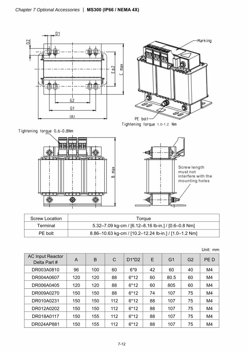
Screw Location Torque Terminal 5.32–7.09 kg-cm / [6.12–8.16 lb-in.] / [0.6–0.8 Nm] PE bolt 8.86–10.63 kg-cm / [10.2–12.24 lb-in.] / [1.0–1.2 Nm]
Unit: mm
AC Input Reactor Delta Part # A B C D1*D2 E G1 G2 PE D
DR003A0810 96 100 60 6*9 42 60 40 M4 DR004A0607 120 120 88 6*12 60 80.5 60 M4 DR006A0405 120 120 88 6*12 60 805 60 M4 DR009A0270 150 150 88 6*12 74 107 75 M4 DR010A0231 150 150 112 6*12 88 107 75 M4 DR012A0202 150 150 112 6*12 88 107 75 M4 DR018A0117 150 155 112 6*12 88 107 75 M4
DR024AP881 150 155 112 6*12 88 107 75 M4
Chapter 7 Optional Accessories MS300 (IP66 / NEMA 4X)
7-13
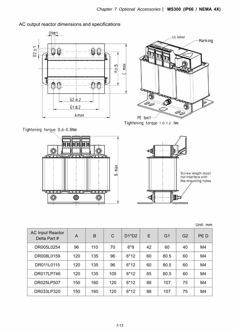
AC output reactor dimensions and specifications
Unit: mm
AC Input Reactor Delta Part # A B C D1*D2 E G1 G2 PE D
DR005L0254 96 110 70 6*9 42 60 40 M4
DR008L0159 120 135 96 6*12 60 80.5 60 M4
DR011L0115 120 135 96 6*12 60 80.5 60 M4
DR017LP746 120 135 105 6*12 65 80.5 60 M4
DR025LP507 150 160 120 6*12 88 107 75 M4
DR033LP320 150 160 120 6*12 88 107 75 M4
Chapter 7 Optional Accessories MS300 (IP66 / NEMA 4X)
7-14
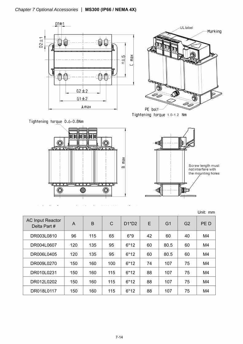
Unit: mm
AC Input Reactor Delta Part # A B C D1*D2 E G1 G2 PE D
DR003L0810 96 115 65 6*9 42 60 40 M4
DR004L0607 120 135 95 6*12 60 80.5 60 M4
DR006L0405 120 135 95 6*12 60 80.5 60 M4
DR009L0270 150 160 100 6*12 74 107 75 M4
DR010L0231 150 160 115 6*12 88 107 75 M4
DR012L0202 150 160 115 6*12 88 107 75 M4
DR018L0117 150 160 115 6*12 88 107 75 M4
Chapter 7 Optional Accessories MS300 (IP66 / NEMA 4X)
7-15
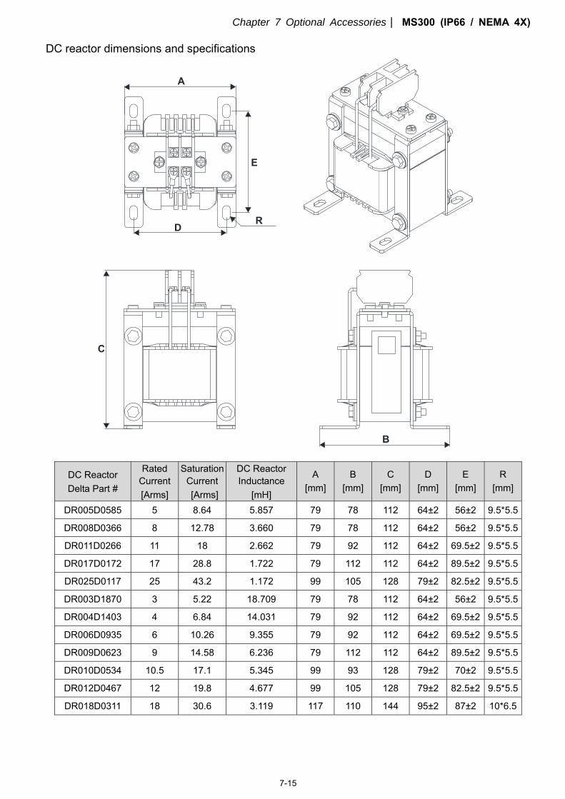
DC reactor dimensions and specifications
DC Reactor Delta Part #
Rated Current [Arms]
Saturation Current [Arms]
DC Reactor Inductance
[mH]
A [mm]
B [mm]
C [mm]
D [mm]
E [mm]
R [mm]
DR005D0585 5 8.64 5.857 79 78 112 64±2 56±2 9.5*5.5
DR008D0366 8 12.78 3.660 79 78 112 64±2 56±2 9.5*5.5
DR011D0266 11 18 2.662 79 92 112 64±2 69.5±2 9.5*5.5
DR017D0172 17 28.8 1.722 79 112 112 64±2 89.5±2 9.5*5.5
DR025D0117 25 43.2 1.172 99 105 128 79±2 82.5±2 9.5*5.5
DR003D1870 3 5.22 18.709 79 78 112 64±2 56±2 9.5*5.5
DR004D1403 4 6.84 14.031 79 92 112 64±2 69.5±2 9.5*5.5
DR006D0935 6 10.26 9.355 79 92 112 64±2 69.5±2 9.5*5.5
DR009D0623 9 14.58 6.236 79 112 112 64±2 89.5±2 9.5*5.5
DR010D0534 10.5 17.1 5.345 99 93 128 79±2 70±2 9.5*5.5
DR012D0467 12 19.8 4.677 99 105 128 79±2 82.5±2 9.5*5.5
DR018D0311 18 30.6 3.119 117 110 144 95±2 87±2 10*6.5
Chapter 7 Optional Accessories MS300 (IP66 / NEMA 4X)
7-16
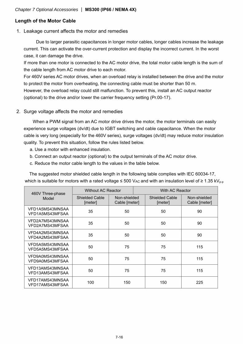
Length of the Motor Cable
1. Leakage current affects the motor and remedies
Due to larger parasitic capacitances in longer motor cables, longer cables increase the leakage current. This can activate the over-current protection and display the incorrect current. In the worst case, it can damage the drive. If more than one motor is connected to the AC motor drive, the total motor cable length is the sum of the cable length from AC motor drive to each motor. For 460V series AC motor drives, when an overload relay is installed between the drive and the motor to protect the motor from overheating, the connecting cable must be shorter than 50 m. However, the overload relay could still malfunction. To prevent this, install an AC output reactor (optional) to the drive and/or lower the carrier frequency setting (Pr.00-17).
2. Surge voltage affects the motor and remedies
When a PWM signal from an AC motor drive drives the motor, the motor terminals can easily experience surge voltages (dv/dt) due to IGBT switching and cable capacitance. When the motor cable is very long (especially for the 460V series), surge voltages (dv/dt) may reduce motor insulation quality. To prevent this situation, follow the rules listed below.
a. Use a motor with enhanced insulation. b. Connect an output reactor (optional) to the output terminals of the AC motor drive. c. Reduce the motor cable length to the values in the table below.
The suggested motor shielded cable length in the following table complies with IEC 60034-17, which is suitable for motors with a rated voltage ≤ 500 VAC and with an insulation level of ≥ 1.35 kVp-p
460V Three-phase Model
Without AC Reactor With AC Reactor
Shielded Cable [meter]
Non-shielded Cable [meter]
Shielded Cable [meter]
Non-shielded Cable [meter]
VFD1A5MS43MNSAA VFD1A5MS43MFSAA 35 50 50 90
VFD2A7MS43MNSAA VFD2A7MS43MFSAA 35 50 50 90
VFD4A2MS43MNSAA VFD4A2MS43MFSAA 35 50 50 90
VFD5A5MS43MNSAA VFD5A5MS43MFSAA 50 75 75 115
VFD9A0MS43MNSAA VFD9A0MS43MFSAA 50 75 75 115
VFD13AMS43MNSAA VFD13AMS43MFSAA 50 75 75 115
VFD17AMS43MNSAA VFD17AMS43MFSAA 100 150 150 225
Chapter 7 Optional Accessories MS300 (IP66 / NEMA 4X)
7-17
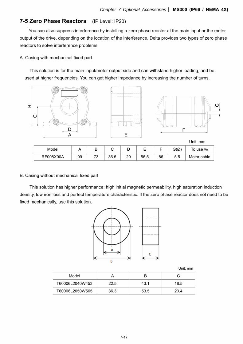
7-5 Zero Phase Reactors (IP Level: IP20)
You can also suppress interference by installing a zero phase reactor at the main input or the motor output of the drive, depending on the location of the interference. Delta provides two types of zero phase reactors to solve interference problems.
A. Casing with mechanical fixed part
This solution is for the main input/motor output side and can withstand higher loading, and be used at higher frequencies. You can get higher impedance by increasing the number of turns.
AD
CB
E
G
F
Unit: mm
Model A B C D E F G(Ø) To use w/
RF008X00A 99 73 36.5 29 56.5 86 5.5 Motor cable
B. Casing without mechanical fixed part
This solution has higher performance: high initial magnetic permeability, high saturation induction density, low iron loss and perfect temperature characteristic. If the zero phase reactor does not need to be fixed mechanically, use this solution.
Unit: mm
Model A B C
T60006L2040W453 22.5 43.1 18.5
T60006L2050W565 36.3 53.5 23.4
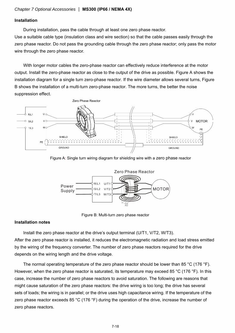
Chapter 7 Optional Accessories MS300 (IP66 / NEMA 4X)
7-18
Installation
During installation, pass the cable through at least one zero phase reactor. Use a suitable cable type (insulation class and wire section) so that the cable passes easily through the zero phase reactor. Do not pass the grounding cable through the zero phase reactor; only pass the motor wire through the zero phase reactor.
With longer motor cables the zero-phase reactor can effectively reduce interference at the motor output. Install the zero-phase reactor as close to the output of the drive as possible. Figure A shows the installation diagram for a single turn zero-phase reactor. If the wire diameter allows several turns, Figure B shows the installation of a multi-turn zero-phase reactor. The more turns, the better the noise suppression effect.
Figure A: Single turn wiring diagram for shielding wire with a zero phase reactor
PowerSupply
Zero Phase Reactor
MOTORU/T1
V/T2
W/T3
R/L1
S/L2
T/L3
Figure B: Multi-turn zero phase reactor
Installation notes
Install the zero phase reactor at the drive’s output terminal (U/T1, V/T2, W/T3). After the zero phase reactor is installed, it reduces the electromagnetic radiation and load stress emitted by the wiring of the frequency converter. The number of zero phase reactors required for the drive depends on the wiring length and the drive voltage.
The normal operating temperature of the zero phase reactor should be lower than 85 °C (176 °F). However, when the zero phase reactor is saturated, its temperature may exceed 85 °C (176 °F). In this case, increase the number of zero phase reactors to avoid saturation. The following are reasons that might cause saturation of the zero phase reactors: the drive wiring is too long; the drive has several sets of loads; the wiring is in parallel; or the drive uses high capacitance wiring. If the temperature of the zero phase reactor exceeds 85 °C (176 °F) during the operation of the drive, increase the number of zero phase reactors.
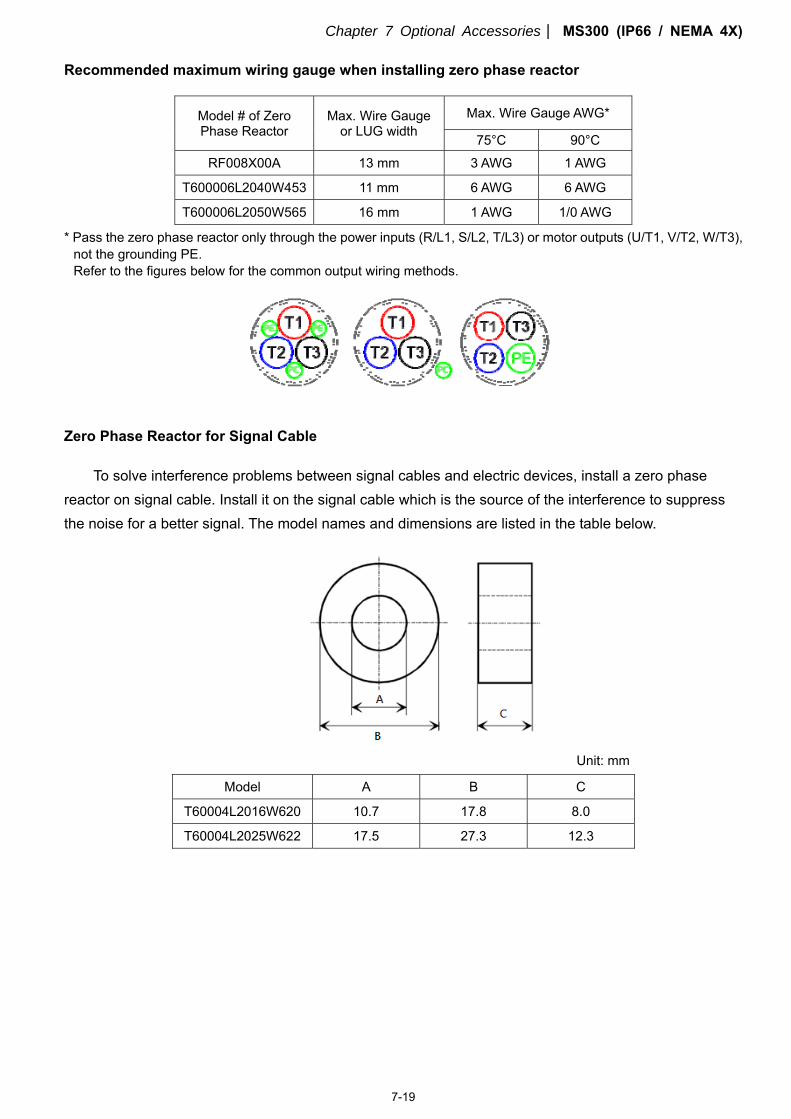
Chapter 7 Optional Accessories MS300 (IP66 / NEMA 4X)
7-19
Recommended maximum wiring gauge when installing zero phase reactor
Model # of Zero Phase Reactor
Max. Wire Gauge or LUG width
Max. Wire Gauge AWG*
75°C 90°C
RF008X00A 13 mm 3 AWG 1 AWG
T600006L2040W453 11 mm 6 AWG 6 AWG
T600006L2050W565 16 mm 1 AWG 1/0 AWG
* Pass the zero phase reactor only through the power inputs (R/L1, S/L2, T/L3) or motor outputs (U/T1, V/T2, W/T3), not the grounding PE. Refer to the figures below for the common output wiring methods.
Zero Phase Reactor for Signal Cable
To solve interference problems between signal cables and electric devices, install a zero phase reactor on signal cable. Install it on the signal cable which is the source of the interference to suppress the noise for a better signal. The model names and dimensions are listed in the table below.
Unit: mm
Model A B C
T60004L2016W620 10.7 17.8 8.0
T60004L2025W622 17.5 27.3 12.3
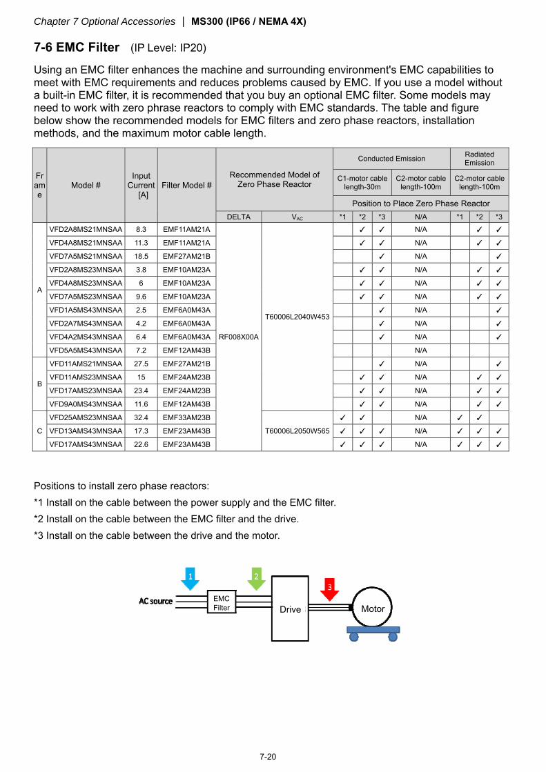
Chapter 7 Optional Accessories MS300 (IP66 / NEMA 4X)
7-20
7-6 EMC Filter (IP Level: IP20)
Using an EMC filter enhances the machine and surrounding environment's EMC capabilities to meet with EMC requirements and reduces problems caused by EMC. If you use a model without a built-in EMC filter, it is recommended that you buy an optional EMC filter. Some models may need to work with zero phrase reactors to comply with EMC standards. The table and figure below show the recommended models for EMC filters and zero phase reactors, installation methods, and the maximum motor cable length.
Frame
Model # Input
Current [A]
Filter Model # Recommended Model of
Zero Phase Reactor
Conducted Emission Radiated Emission
C1-motor cable length-30m
C2-motor cable length-100m
C2-motor cable length-100m
Position to Place Zero Phase Reactor DELTA VAC *1 *2 *3 N/A *1 *2 *3
A
VFD2A8MS21MNSAA 8.3 EMF11AM21A
RF008X00A
T60006L2040W453
N/A
VFD4A8MS21MNSAA 11.3 EMF11AM21A N/A
VFD7A5MS21MNSAA 18.5 EMF27AM21B N/A
VFD2A8MS23MNSAA 3.8 EMF10AM23A N/A
VFD4A8MS23MNSAA 6 EMF10AM23A N/A
VFD7A5MS23MNSAA 9.6 EMF10AM23A N/A
VFD1A5MS43MNSAA 2.5 EMF6A0M43A N/A
VFD2A7MS43MNSAA 4.2 EMF6A0M43A N/A
VFD4A2MS43MNSAA 6.4 EMF6A0M43A N/A
VFD5A5MS43MNSAA 7.2 EMF12AM43B N/A
B
VFD11AMS21MNSAA 27.5 EMF27AM21B N/A
VFD11AMS23MNSAA 15 EMF24AM23B N/A
VFD17AMS23MNSAA 23.4 EMF24AM23B N/A
VFD9A0MS43MNSAA 11.6 EMF12AM43B N/A
C
VFD25AMS23MNSAA 32.4 EMF33AM23B
T60006L2050W565
N/A
VFD13AMS43MNSAA 17.3 EMF23AM43B N/A
VFD17AMS43MNSAA 22.6 EMF23AM43B N/A
Positions to install zero phase reactors: *1 Install on the cable between the power supply and the EMC filter. *2 Install on the cable between the EMC filter and the drive. *3 Install on the cable between the drive and the motor.
EMC Filter Motor Drive
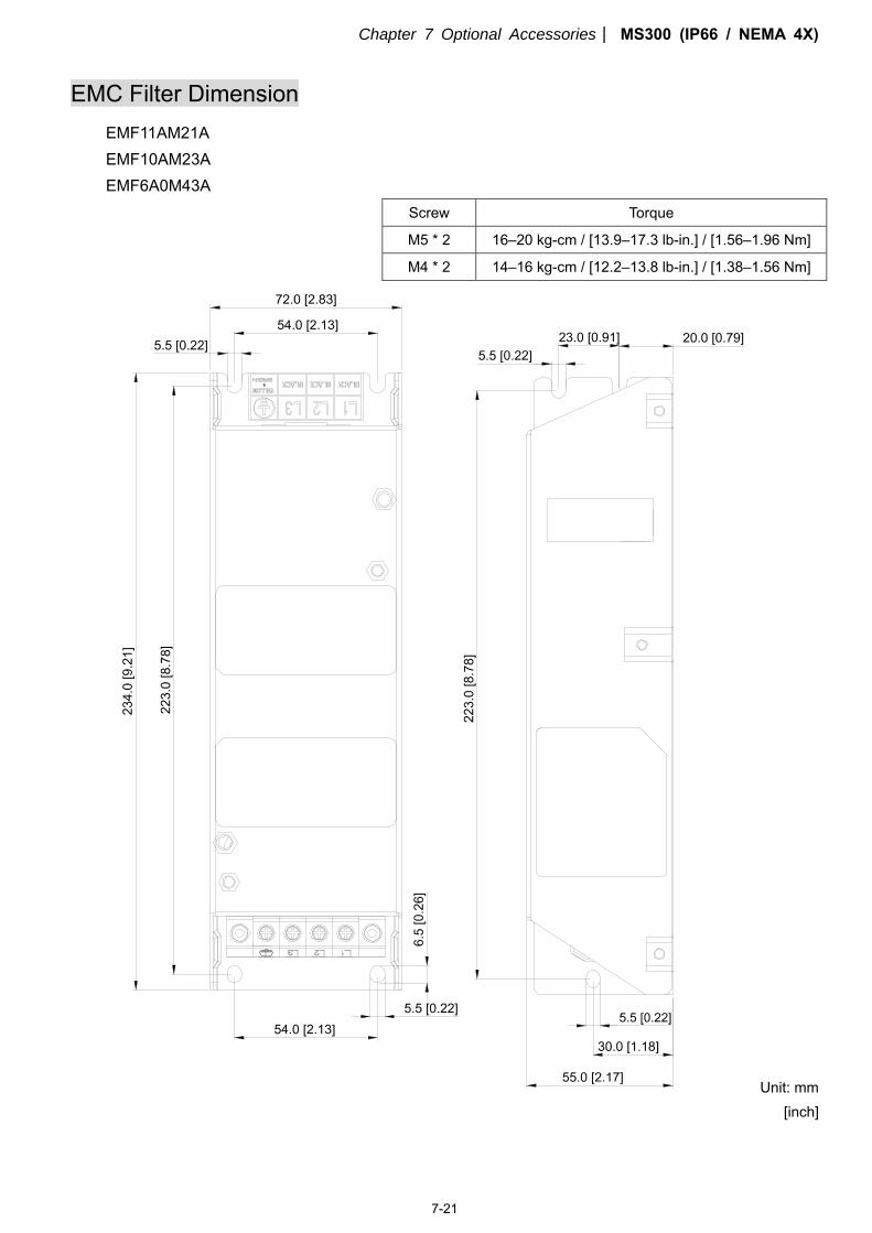
Chapter 7 Optional Accessories MS300 (IP66 / NEMA 4X)
7-21
EMC Filter Dimension EMF11AM21A EMF10AM23A EMF6A0M43A
Screw Torque
M5 * 2 16–20 kg-cm / [13.9–17.3 lb-in.] / [1.56–1.96 Nm]
M4 * 2 14–16 kg-cm / [12.2–13.8 lb-in.] / [1.38–1.56 Nm]
Unit: mm [inch]
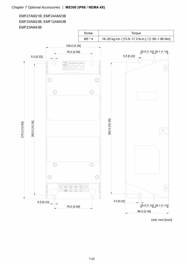
Chapter 7 Optional Accessories MS300 (IP66 / NEMA 4X)
7-22
EMF27AM21B; EMF24AM23B EMF33AM23B; EMF12AM43B EMF23AM43B
Screw Torque
M5 * 4 16–20 kg-cm / [13.9–17.3 lb-in.] / [1.56–1.96 Nm]
Unit: mm [inch]
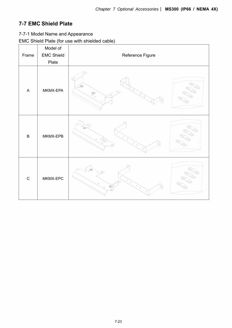
Chapter 7 Optional Accessories MS300 (IP66 / NEMA 4X)
7-23
7-7 EMC Shield Plate
7-7-1 Model Name and Appearance EMC Shield Plate (for use with shielded cable)
Frame
Model of EMC Shield
Plate
Reference Figure
A MKMX-EPA
B MKMX-EPB
C MKMX-EPC
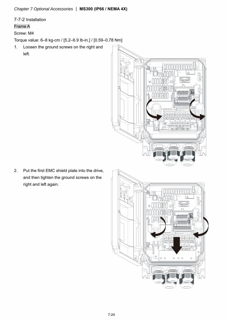
Chapter 7 Optional Accessories MS300 (IP66 / NEMA 4X)
7-24
7-7-2 Installation
Frame A Screw: M4 Torque value: 6–8 kg-cm / [5.2–6.9 lb-in.] / [0.59–0.78 Nm] 1. Loosen the ground screws on the right and
left.
2. Put the first EMC shield plate into the drive,
and then tighten the ground screws on the right and left again.
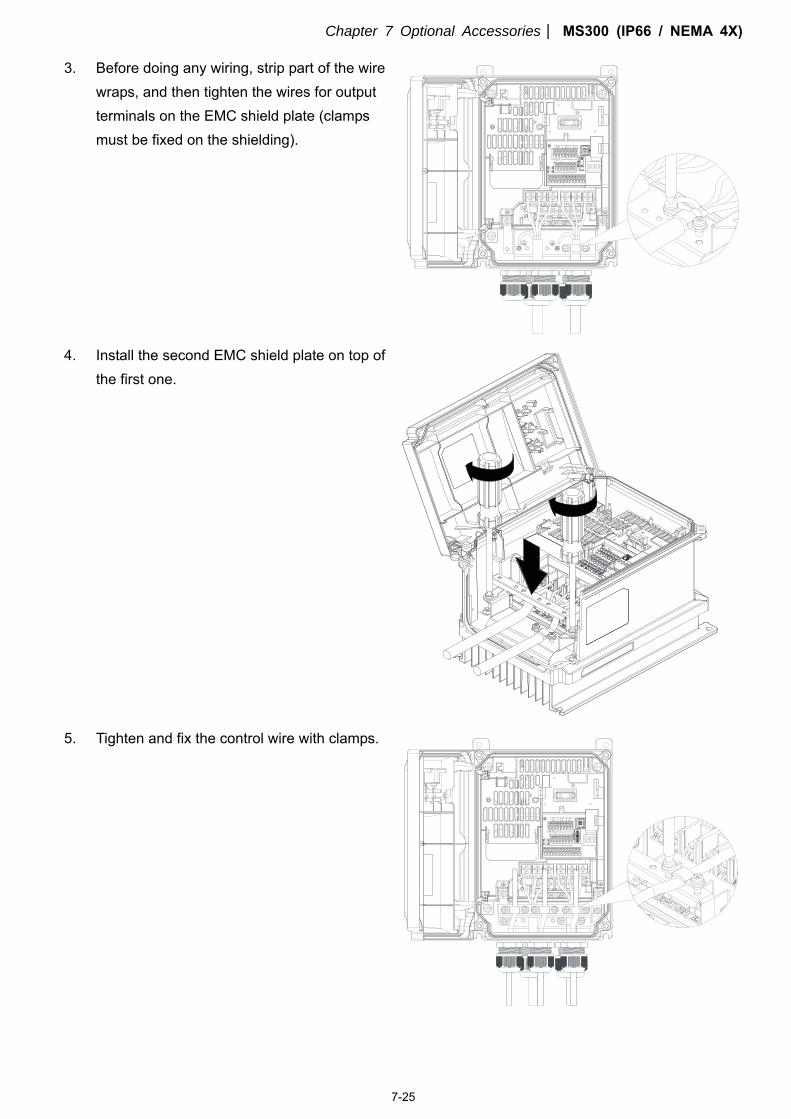
Chapter 7 Optional Accessories MS300 (IP66 / NEMA 4X)
7-25
3. Before doing any wiring, strip part of the wire wraps, and then tighten the wires for output terminals on the EMC shield plate (clamps must be fixed on the shielding).
4. Install the second EMC shield plate on top of
the first one.
5. Tighten and fix the control wire with clamps.
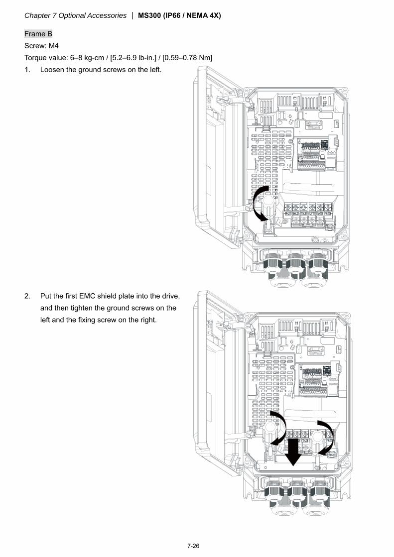
Chapter 7 Optional Accessories MS300 (IP66 / NEMA 4X)
7-26
Frame B Screw: M4 Torque value: 6–8 kg-cm / [5.2–6.9 lb-in.] / [0.59–0.78 Nm] 1. Loosen the ground screws on the left.
2. Put the first EMC shield plate into the drive,
and then tighten the ground screws on the left and the fixing screw on the right.
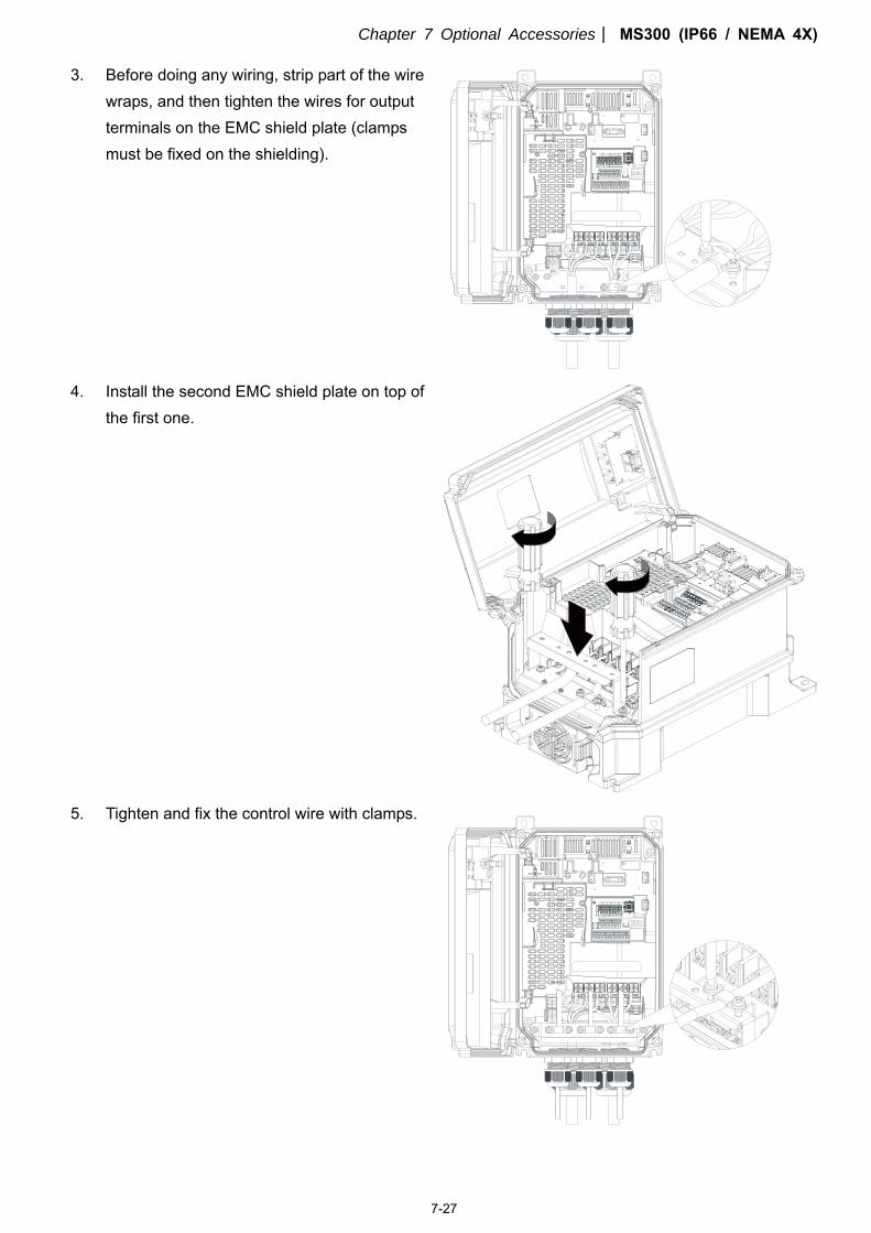
Chapter 7 Optional Accessories MS300 (IP66 / NEMA 4X)
7-27
3. Before doing any wiring, strip part of the wire wraps, and then tighten the wires for output terminals on the EMC shield plate (clamps must be fixed on the shielding).
4. Install the second EMC shield plate on top of
the first one.
5. Tighten and fix the control wire with clamps.
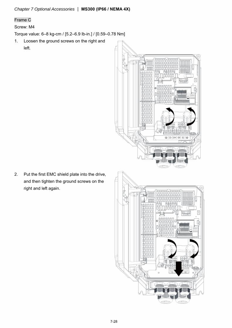
Chapter 7 Optional Accessories MS300 (IP66 / NEMA 4X)
7-28
Frame C Screw: M4 Torque value: 6–8 kg-cm / [5.2–6.9 lb-in.] / [0.59–0.78 Nm] 1. Loosen the ground screws on the right and
left.
2. Put the first EMC shield plate into the drive, and then tighten the ground screws on the right and left again.
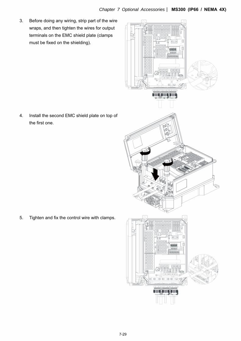
Chapter 7 Optional Accessories MS300 (IP66 / NEMA 4X)
7-29
3. Before doing any wiring, strip part of the wire wraps, and then tighten the wires for output terminals on the EMC shield plate (clamps must be fixed on the shielding).
4. Install the second EMC shield plate on top of
the first one.
5. Tighten and fix the control wire with clamps.
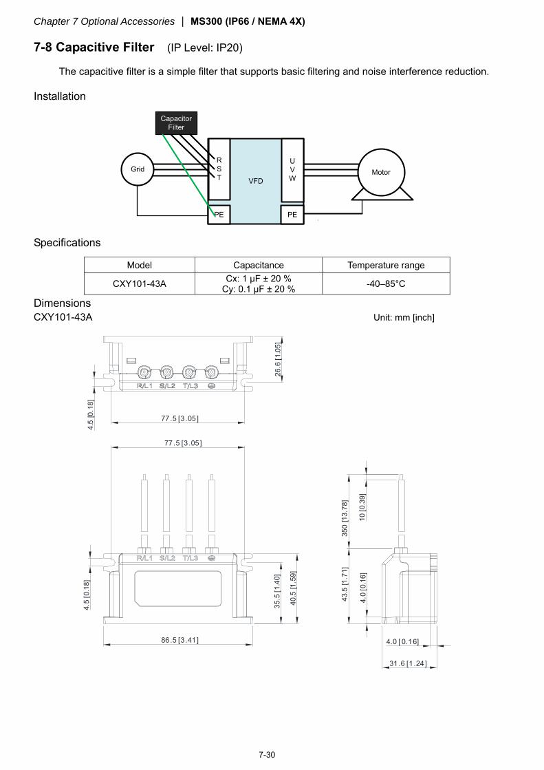
Chapter 7 Optional Accessories MS300 (IP66 / NEMA 4X)
7-30
7-8 Capacitive Filter (IP Level: IP20)
The capacitive filter is a simple filter that supports basic filtering and noise interference reduction.
Installation
VFD
RST
UVW
PE
Motor
PE
Grid
Capacitor Filter
Specifications
Model Capacitance Temperature range
CXY101-43A Cx: 1 μF ± 20 % Cy: 0.1 μF ± 20 % -40–85°C
Dimensions CXY101-43A Unit: mm [inch]
77.5 [3 .05]
26.6
[1.0
5]
4.5
[0.1
8]
86.5 [3 .41]
35.5
[1.4
0]
40.5
[1.5
9]
77 .5 [3.05]
4.5
[0.1
8]
350
[13.
78]
10[0
.39]
43.5
[1.7
1]
4.0
[0.1
6]
31 .6 [1 .24]
4.0 [ 0.16]
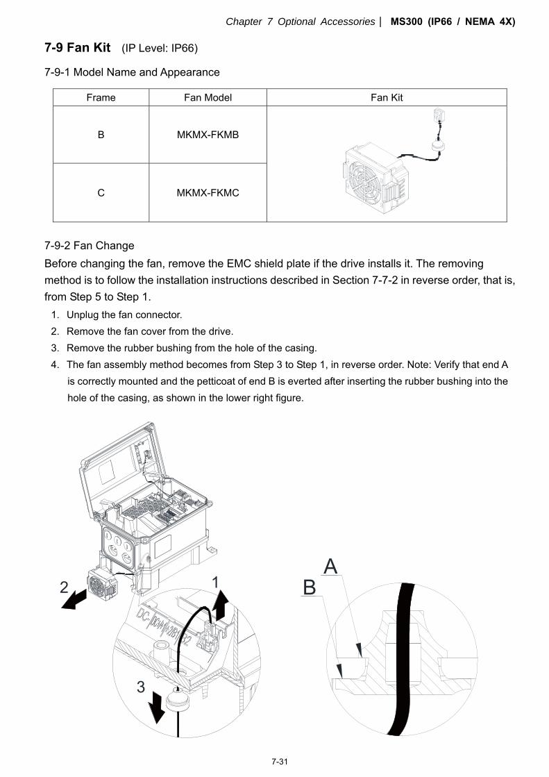
Chapter 7 Optional Accessories MS300 (IP66 / NEMA 4X)
7-31
7-9 Fan Kit (IP Level: IP66)
7-9-1 Model Name and Appearance
Frame Fan Model Fan Kit
B MKMX-FKMB
C MKMX-FKMC
7-9-2 Fan Change Before changing the fan, remove the EMC shield plate if the drive installs it. The removing method is to follow the installation instructions described in Section 7-7-2 in reverse order, that is, from Step 5 to Step 1.
1. Unplug the fan connector. 2. Remove the fan cover from the drive. 3. Remove the rubber bushing from the hole of the casing. 4. The fan assembly method becomes from Step 3 to Step 1, in reverse order. Note: Verify that end A
is correctly mounted and the petticoat of end B is everted after inserting the rubber bushing into the hole of the casing, as shown in the lower right figure.
2
3
1 BA
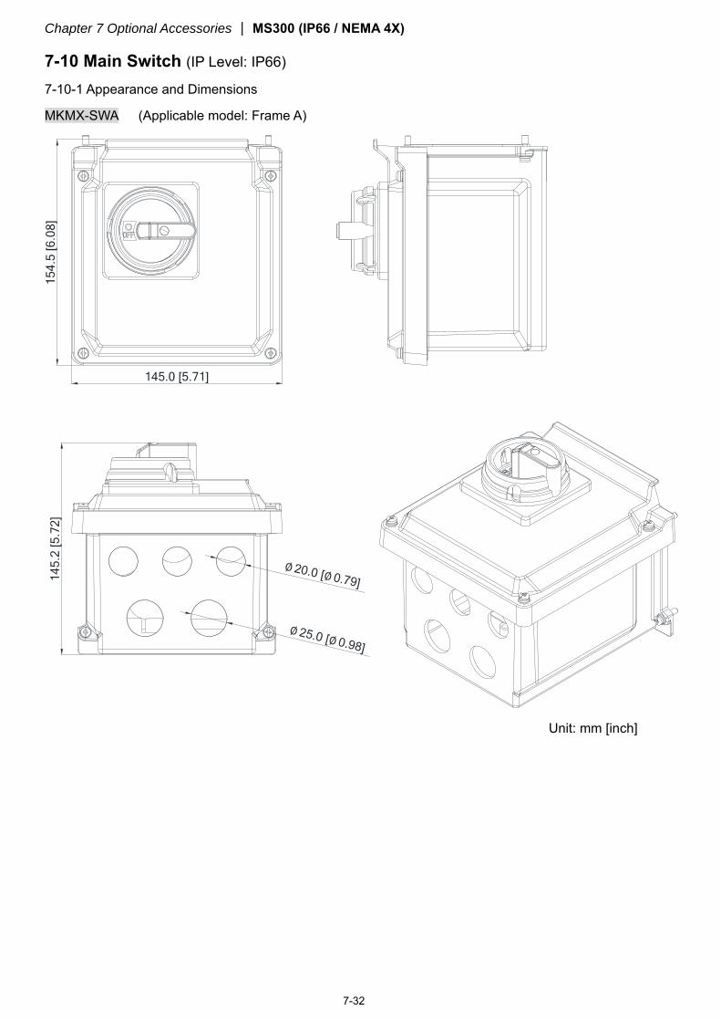
Chapter 7 Optional Accessories MS300 (IP66 / NEMA 4X)
7-32
7-10 Main Switch (IP Level: IP66)
7-10-1 Appearance and Dimensions
MKMX-SWA (Applicable model: Frame A)
Unit: mm [inch]
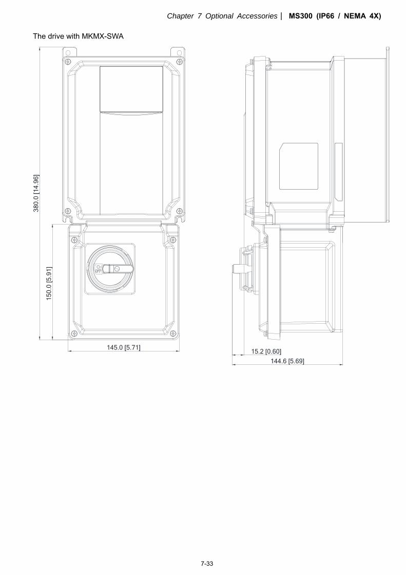
Chapter 7 Optional Accessories MS300 (IP66 / NEMA 4X)
7-33
The drive with MKMX-SWA
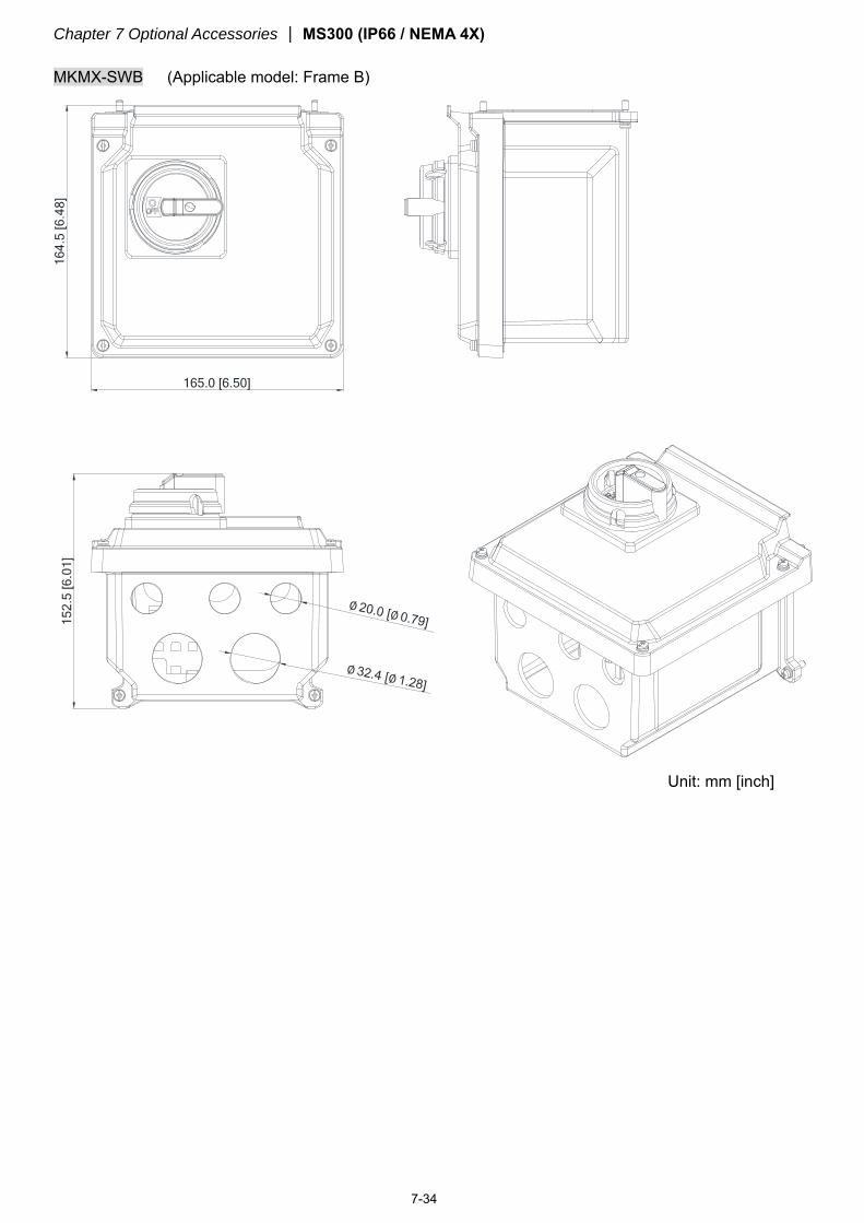
Chapter 7 Optional Accessories MS300 (IP66 / NEMA 4X)
7-34
MKMX-SWB (Applicable model: Frame B)
Unit: mm [inch]
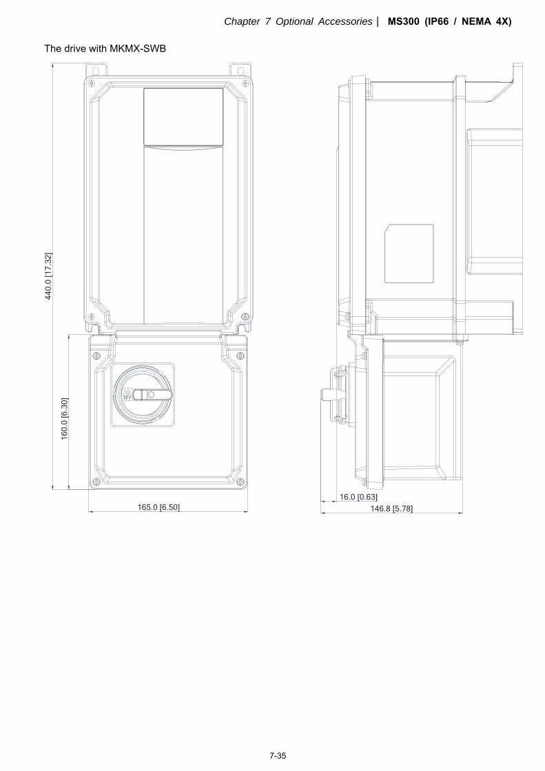
Chapter 7 Optional Accessories MS300 (IP66 / NEMA 4X)
7-35
The drive with MKMX-SWB
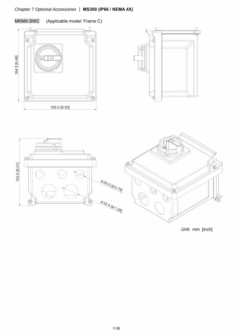
Chapter 7 Optional Accessories MS300 (IP66 / NEMA 4X)
7-36
MKMX-SWC (Applicable model: Frame C)
Unit: mm [inch]
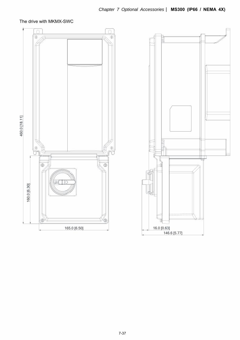
Chapter 7 Optional Accessories MS300 (IP66 / NEMA 4X)
7-37
The drive with MKMX-SWC
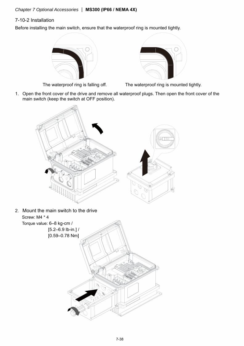
Chapter 7 Optional Accessories MS300 (IP66 / NEMA 4X)
7-38
7-10-2 Installation Before installing the main switch, ensure that the waterproof ring is mounted tightly.
The waterproof ring is falling off. The waterproof ring is mounted tightly.
1. Open the front cover of the drive and remove all waterproof plugs. Then open the front cover of the main switch (keep the switch at OFF position).
2. Mount the main switch to the drive
Screw: M4 * 4 Torque value: 6–8 kg-cm /
[5.2–6.9 lb-in.] / [0.59–0.78 Nm]
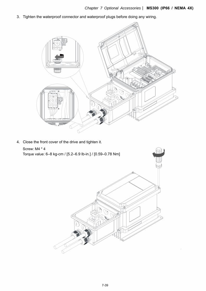
Chapter 7 Optional Accessories MS300 (IP66 / NEMA 4X)
7-39
3. Tighten the waterproof connector and waterproof plugs before doing any wiring.
L2
L1
L3
L2 L3
L1
4. Close the front cover of the drive and tighten it.
Screw: M4 * 4 Torque value: 6–8 kg-cm / [5.2–6.9 lb-in.] / [0.59–0.78 Nm]
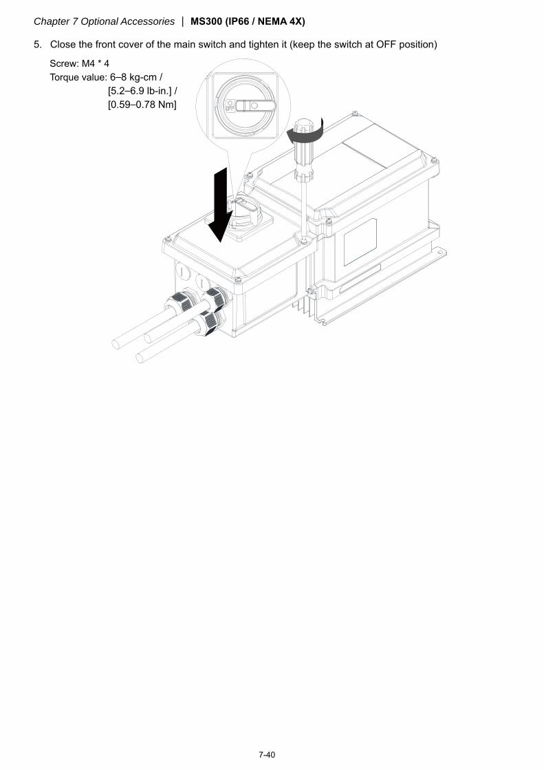
Chapter 7 Optional Accessories MS300 (IP66 / NEMA 4X)
7-40
5. Close the front cover of the main switch and tighten it (keep the switch at OFF position)
Screw: M4 * 4 Torque value: 6–8 kg-cm /
[5.2–6.9 lb-in.] / [0.59–0.78 Nm]
Chapter 8 Optional Cards MS300 (IP66 / NEMA 4X)
8-1
Chapter 8 Option Cards
8-1 Option Card Installation
8-2 CMM-MOD01 -- Communication Extension Card, Modbus TCP
8-3 CMM-PD01 -- Communication Extension Card, PROFIBUS DP
8-4 CMM-DN01 -- Communication Extension Card, DeviceNet
8-5 CMM-EIP01 -- Communication Extension Card, EtherNet/IP
8-6 CMM-COP01 -- Communication Extension Card, CANopen
8-7 EMM-BPS01 -- +24 V Power Extension Card
8-8 Delta Bus Standard Wire
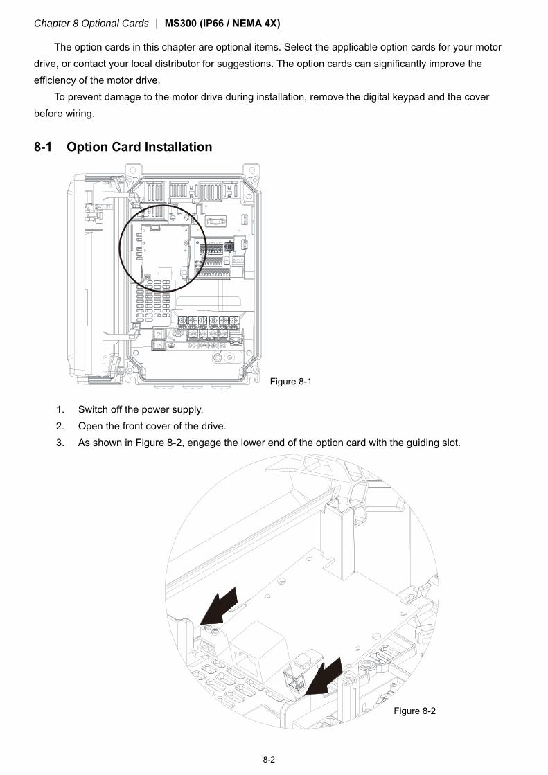
Chapter 8 Optional Cards MS300 (IP66 / NEMA 4X)
8-2
The option cards in this chapter are optional items. Select the applicable option cards for your motor drive, or contact your local distributor for suggestions. The option cards can significantly improve the efficiency of the motor drive.
To prevent damage to the motor drive during installation, remove the digital keypad and the cover before wiring.
8-1 Option Card Installation
1. Switch off the power supply. 2. Open the front cover of the drive. 3. As shown in Figure 8-2, engage the lower end of the option card with the guiding slot.
Figure 8-1
Figure 8-2
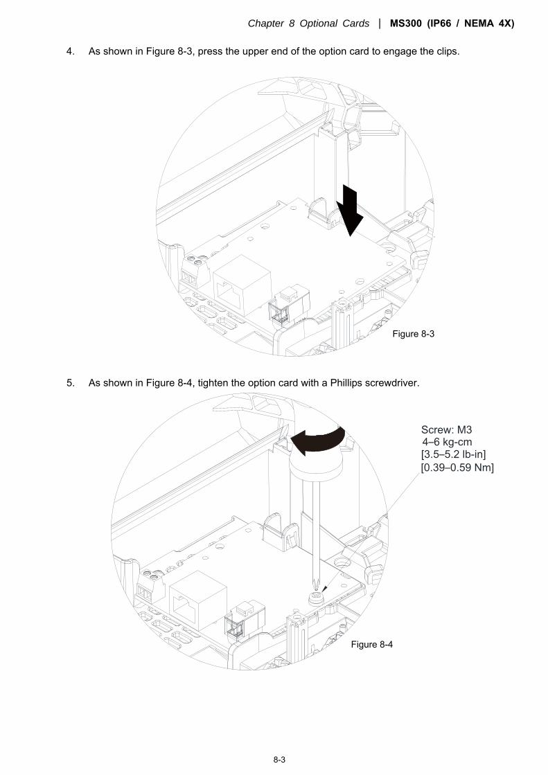
Chapter 8 Optional Cards MS300 (IP66 / NEMA 4X)
8-3
4. As shown in Figure 8-3, press the upper end of the option card to engage the clips.
5. As shown in Figure 8-4, tighten the option card with a Phillips screwdriver.
Figure 8-3
Figure 8-4
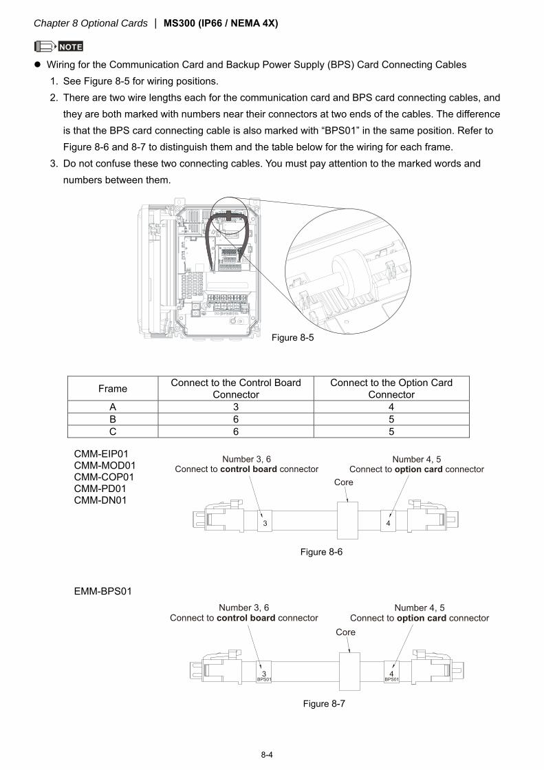
Chapter 8 Optional Cards MS300 (IP66 / NEMA 4X)
8-4
NOTE Wiring for the Communication Card and Backup Power Supply (BPS) Card Connecting Cables
1. See Figure 8-5 for wiring positions. 2. There are two wire lengths each for the communication card and BPS card connecting cables, and
they are both marked with numbers near their connectors at two ends of the cables. The difference is that the BPS card connecting cable is also marked with “BPS01” in the same position. Refer to Figure 8-6 and 8-7 to distinguish them and the table below for the wiring for each frame.
3. Do not confuse these two connecting cables. You must pay attention to the marked words and numbers between them.
Frame Connect to the Control Board Connector
Connect to the Option Card Connector
A 3 4 B 6 5 C 6 5
CMM-EIP01 CMM-MOD01 CMM-COP01 CMM-PD01 CMM-DN01
EMM-BPS01
Figure 8-6
Figure 8-7
Figure 8-5
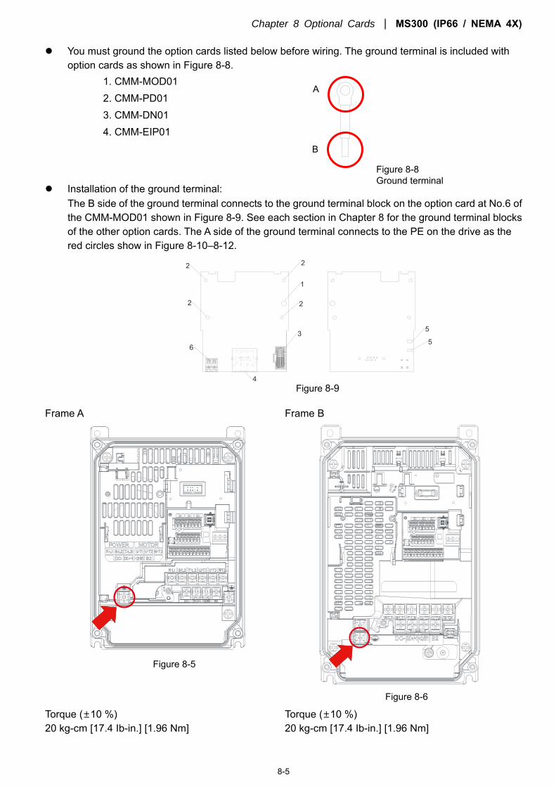
Chapter 8 Optional Cards MS300 (IP66 / NEMA 4X)
8-5
You must ground the option cards listed below before wiring. The ground terminal is included with option cards as shown in Figure 8-8.
1. CMM-MOD01 2. CMM-PD01 3. CMM-DN01 4. CMM-EIP01
Installation of the ground terminal: The B side of the ground terminal connects to the ground terminal block on the option card at No.6 of the CMM-MOD01 shown in Figure 8-9. See each section in Chapter 8 for the ground terminal blocks of the other option cards. The A side of the ground terminal connects to the PE on the drive as the red circles show in Figure 8-10–8-12.
4
3
6
2 2
2
1
5
5
2
Frame A Frame B
Torque (±10 %) 20 kg-cm [17.4 Ib-in.] [1.96 Nm]
Torque (±10 %) 20 kg-cm [17.4 Ib-in.] [1.96 Nm]
A
B
Figure 8-9
Figure 8-5
Figure 8-8 Ground terminal
Figure 8-6
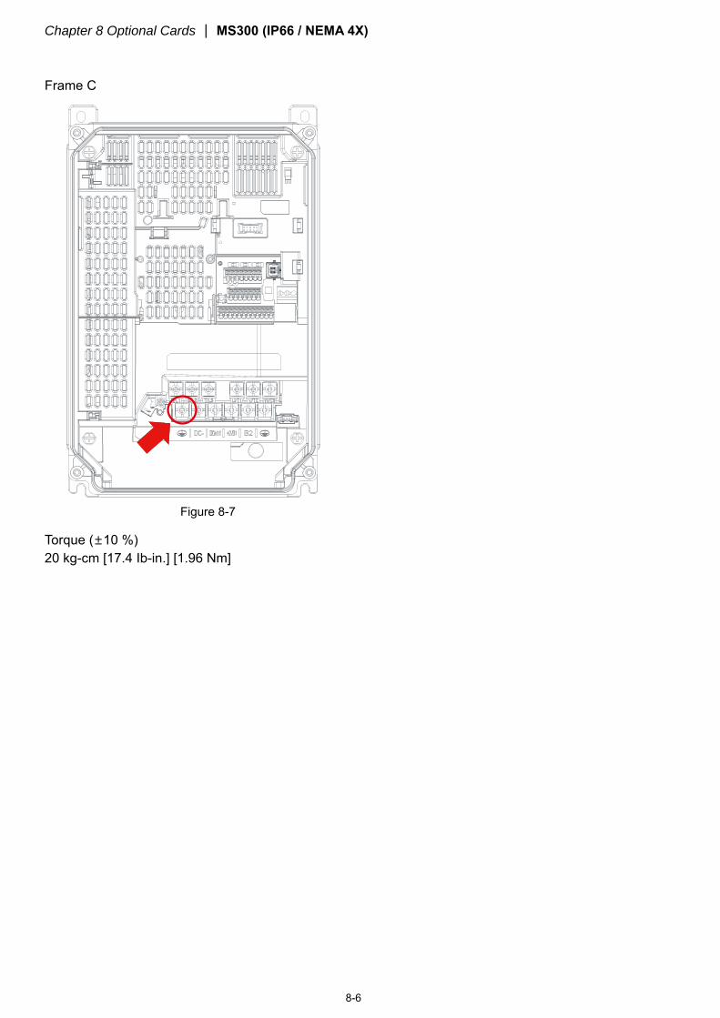
Chapter 8 Optional Cards MS300 (IP66 / NEMA 4X)
8-6
Frame C
Torque (±10 %) 20 kg-cm [17.4 Ib-in.] [1.96 Nm]
Figure 8-7
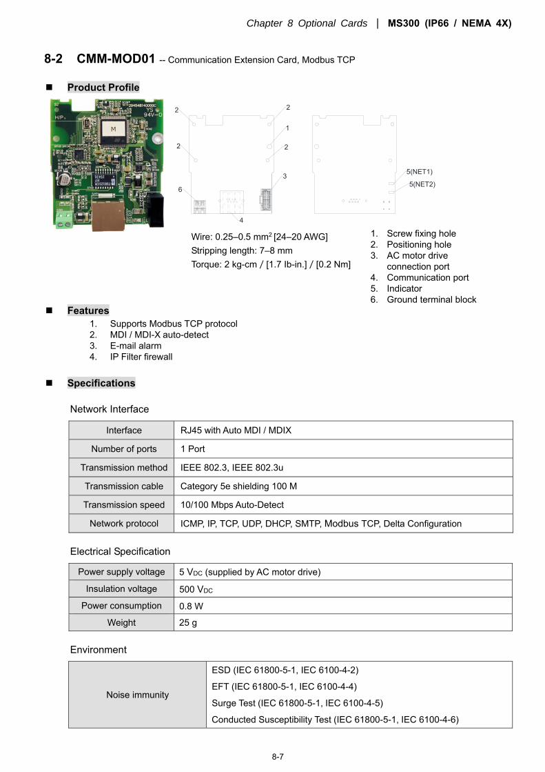
Chapter 8 Optional Cards MS300 (IP66 / NEMA 4X)
8-7
8-2 CMM-MOD01 -- Communication Extension Card, Modbus TCP
Product Profile
5(NET2)
5(NET1)
6
2
4
3
2 2
2
1
Features 1. Supports Modbus TCP protocol 2. MDI / MDI-X auto-detect 3. E-mail alarm 4. IP Filter firewall
Specifications
Network Interface
Interface RJ45 with Auto MDI / MDIX
Number of ports 1 Port
Transmission method IEEE 802.3, IEEE 802.3u
Transmission cable Category 5e shielding 100 M
Transmission speed 10/100 Mbps Auto-Detect
Network protocol ICMP, IP, TCP, UDP, DHCP, SMTP, Modbus TCP, Delta Configuration
Electrical Specification
Power supply voltage 5 VDC (supplied by AC motor drive)
Insulation voltage 500 VDC
Power consumption 0.8 W
Weight 25 g
Environment
Noise immunity
ESD (IEC 61800-5-1, IEC 6100-4-2)
EFT (IEC 61800-5-1, IEC 6100-4-4)
Surge Test (IEC 61800-5-1, IEC 6100-4-5)
Conducted Susceptibility Test (IEC 61800-5-1, IEC 6100-4-6)
Wire: 0.25–0.5 mm2 [24–20 AWG] Stripping length: 7–8 mm Torque: 2 kg-cm/[1.7 Ib-in.]/[0.2 Nm]
1. Screw fixing hole 2. Positioning hole 3. AC motor drive
connection port 4. Communication port 5. Indicator 6. Ground terminal block
Chapter 8 Optional Cards MS300 (IP66 / NEMA 4X)
8-8
Operation / Storage Operation: -10–50 °C (temperature), 90 % (humidity)
Storage: -25–70 °C (temperature), 95 % (humidity)
Shock / Vibration resistance International standards: IEC 61800-5-1, IEC 60068-2-6 / IEC 61800-5-1, IEC 60068-2-27
MS300 (IP66 / NEMA 4X) Communication Parameters when Connected to EtherNet
When you connect the MS300 (IP66 / NEMA 4X) to EtherNet, set up the communication parameters based
on the table below. The EtherNet master can read and write frequency command words and operation command
words for the MS300 (IP66 / NEMA 4X) after you set the communication parameters.
Parameter Function Current Set Value Definition of Parameter Values
00-20 Frequency command source 8 The frequency command is controlled by
communication card.
00-21 Operation command source 5 The operation command is controlled by
communication card.
09-30 Decoding method for communication 0 Decoding method for the Delta AC motor
drive. 09-75 IP setting 0 Static IP(0) / Dynamic distribution IP(1) 09-76 IP address 1 192 IP address 192.168.1.5 09-77 IP address 2 168 IP address 192.168.1.5 09-78 IP address 3 1 IP address 192.168.1.5 09-79 IP address 4 5 IP address 192.168.1.5 09-80 Netmask 1 255 Netmask 255.255.255.0 09-81 Netmask 2 255 Netmask 255.255.255.0 09-82 Netmask 3 255 Netmask 255.255.255.0 09-83 Netmask 4 0 Netmask 255.255.255.0 09-84 Default gateway 1 192 Default gateway 192.168.1.1 09-85 Default gateway 2 168 Default gateway 192.168.1.1 09-86 Default gateway 3 1 Default gateway 192.168.1.1 09-87 Default gateway 4 1 Default gateway 192.168.1.1
Basic Registers
BR# R/W Content Set Value
#0 R Model name Defined by the system. The model code of CMM-MOD01=H’0103.
#1 R Firmware version Displays the current firmware version in hex, e.g. H`0100 indicates firmware version V1.00.
#2 R Release date of the version
Displays the date in decimal form. 10,000s digit and 1,000s digit are for “month”; 100s digit and 10s digit are for “day”. For 1 digit: 0 = AM; 1 = PM.
#11 R/W Modbus Time-out Pre-defined setting: 500 (ms)
#13 R/W Keep Alive Time Pre-defined setting: 30 (s)
LED Indicator & Troubleshooting
LED Indicators
LED Status Indication Corrective Action
POWER Green On Power supply in normal status No action is required Green Off No power supply Check the power supply
Chapter 8 Optional Cards MS300 (IP66 / NEMA 4X)
8-9
LED Status Indication Corrective Action
LINK Green
On Network connection in normal status No action is required
Flashes Network in operation No action is required
Off Network not connected Check if the network cable is connected
Troubleshooting
Abnormality Cause Corrective Action
POWER LED off
AC motor drive not powered Check if AC motor drive is powered, and if the power supply is normal.
The CMM-MOD01 not connected to AC motor drive
Make sure CMM-MOD01 is connected to AC motor drive.
LINK LED off Not connected to network Make sure the network cable is correctly connected to
network.
Poor contact to RJ45 connector Make sure the RJ45 connector is connected to EtherNet port.
No module found
The CMM-MOD01 not connected to network
Make sure the CMM-MOD01 is connected to the network.
The PC and the CMM-MOD01 are in different networks and blocked by network firewall.
Search by IP or set up the relevant settings using the AC motor drive keypad.
Fails to open CMM-MOD01 setup page
The CMM-MOD01 is not connected to network
Make sure the CMM-MOD01 is connected to the network.
Incorrect communication setting in DCISoft
Make sure the communication setting in DCISoft is set to EtherNet.
The PC and the CMM-MOD01 are in different networks and blocked by network firewall.
Set up with the AC motor drive keypad.
Able to open CMM-MOD01 setup page but fails to utilize webpage monitoring
Incorrect network setting in the CMM-MOD01
Check if the network setting for the CMM-MOD01 is correct. For the Intranet setting in your company, please consult your IT staff. For the Internet setting at home, please refer to the network setting instruction provided by your ISP.
Fails to send e-mail
Incorrect network setting in the CMM-MOD01
Check if the network setting for the CMM-MOD01 is correct.
Incorrect mail server setting Confirm the IP address for the SMTP-Server.
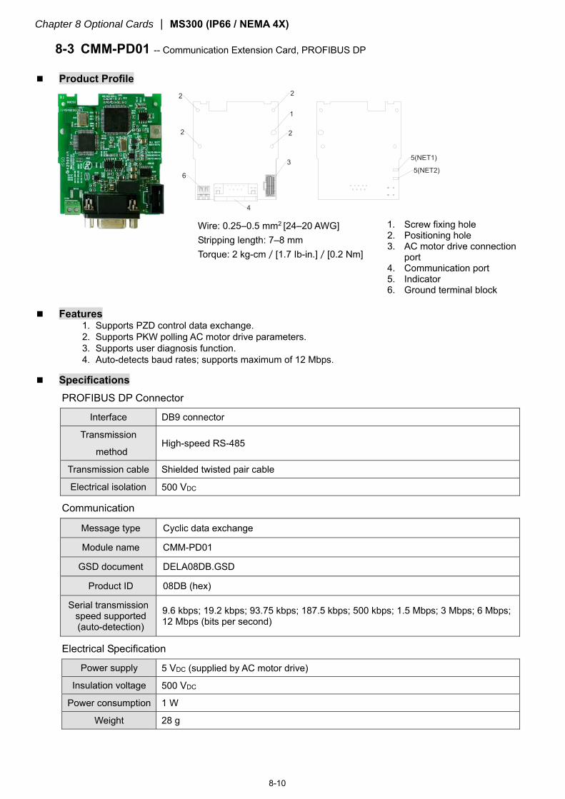
Chapter 8 Optional Cards MS300 (IP66 / NEMA 4X)
8-10
8-3 CMM-PD01 -- Communication Extension Card, PROFIBUS DP
Product Profile 2
4
3
2 2
2
1
5(NET2)
5(NET1)
6
Features 1. Supports PZD control data exchange. 2. Supports PKW polling AC motor drive parameters. 3. Supports user diagnosis function. 4. Auto-detects baud rates; supports maximum of 12 Mbps.
Specifications
PROFIBUS DP Connector
Interface DB9 connector
Transmission
method High-speed RS-485
Transmission cable Shielded twisted pair cable
Electrical isolation 500 VDC
Communication
Message type Cyclic data exchange
Module name CMM-PD01
GSD document DELA08DB.GSD
Product ID 08DB (hex)
Serial transmission speed supported (auto-detection)
9.6 kbps; 19.2 kbps; 93.75 kbps; 187.5 kbps; 500 kbps; 1.5 Mbps; 3 Mbps; 6 Mbps; 12 Mbps (bits per second)
Electrical Specification
Power supply 5 VDC (supplied by AC motor drive)
Insulation voltage 500 VDC
Power consumption 1 W
Weight 28 g
Wire: 0.25–0.5 mm2 [24–20 AWG] Stripping length: 7–8 mm Torque: 2 kg-cm/[1.7 Ib-in.]/[0.2 Nm]
1. Screw fixing hole 2. Positioning hole 3. AC motor drive connection
port 4. Communication port 5. Indicator 6. Ground terminal block
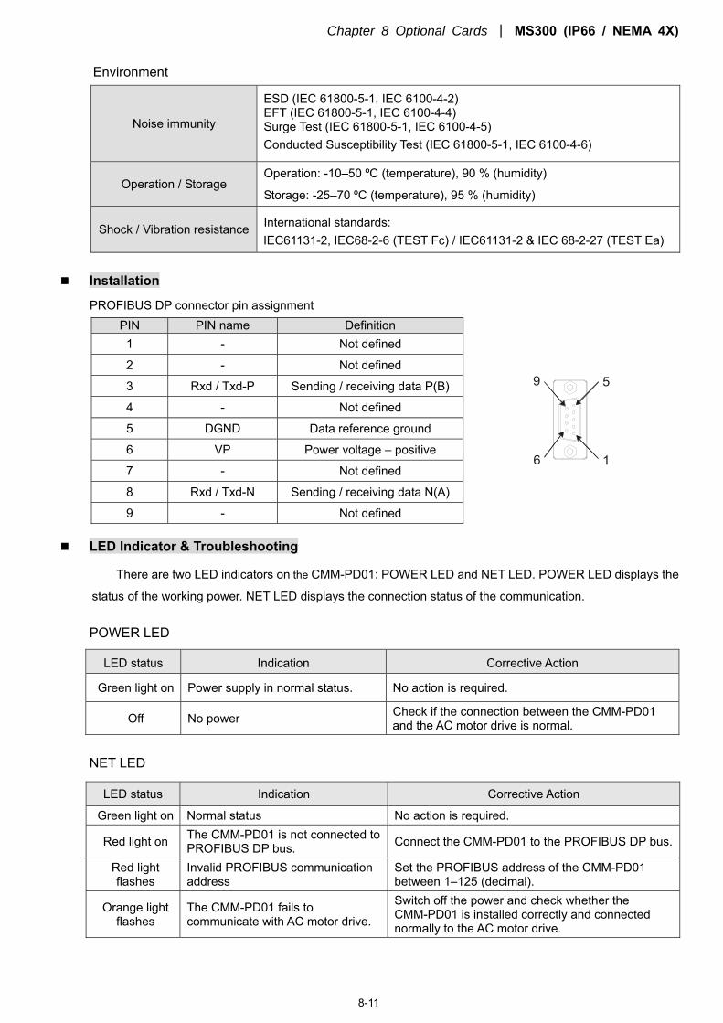
Chapter 8 Optional Cards MS300 (IP66 / NEMA 4X)
8-11
Environment
Noise immunity
ESD (IEC 61800-5-1, IEC 6100-4-2) EFT (IEC 61800-5-1, IEC 6100-4-4) Surge Test (IEC 61800-5-1, IEC 6100-4-5) Conducted Susceptibility Test (IEC 61800-5-1, IEC 6100-4-6)
Operation / Storage Operation: -10–50 ºC (temperature), 90 % (humidity)
Storage: -25–70 ºC (temperature), 95 % (humidity)
Shock / Vibration resistance International standards: IEC61131-2, IEC68-2-6 (TEST Fc) / IEC61131-2 & IEC 68-2-27 (TEST Ea)
Installation
PROFIBUS DP connector pin assignment PIN PIN name Definition
16
59
1 - Not defined
2 - Not defined
3 Rxd / Txd-P Sending / receiving data P(B)
4 - Not defined
5 DGND Data reference ground
6 VP Power voltage – positive
7 - Not defined
8 Rxd / Txd-N Sending / receiving data N(A)
9 - Not defined
LED Indicator & Troubleshooting
There are two LED indicators on the CMM-PD01: POWER LED and NET LED. POWER LED displays the
status of the working power. NET LED displays the connection status of the communication.
POWER LED
LED status Indication Corrective Action
Green light on Power supply in normal status. No action is required.
Off No power Check if the connection between the CMM-PD01 and the AC motor drive is normal.
NET LED
LED status Indication Corrective Action
Green light on Normal status No action is required.
Red light on The CMM-PD01 is not connected to PROFIBUS DP bus. Connect the CMM-PD01 to the PROFIBUS DP bus.
Red light flashes
Invalid PROFIBUS communication address
Set the PROFIBUS address of the CMM-PD01 between 1–125 (decimal).
Orange light flashes
The CMM-PD01 fails to communicate with AC motor drive.
Switch off the power and check whether the CMM-PD01 is installed correctly and connected normally to the AC motor drive.
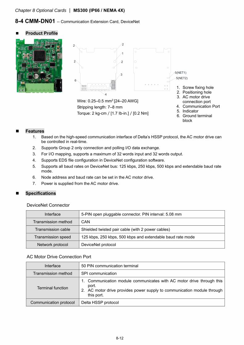
Chapter 8 Optional Cards MS300 (IP66 / NEMA 4X)
8-12
8-4 CMM-DN01 -- Communication Extension Card, DeviceNet
Product Profile
5(NET2)
5(NET1)
2
4
3
2
6
2
2
1
Features 1. Based on the high-speed communication interface of Delta’s HSSP protocol, the AC motor drive can
be controlled in real-time. 2. Supports Group 2 only connection and polling I/O data exchange. 3. For I/O mapping, supports a maximum of 32 words input and 32 words output. 4. Supports EDS file configuration in DeviceNet configuration software. 5. Supports all baud rates on DeviceNet bus: 125 kbps, 250 kbps, 500 kbps and extendable baud rate
mode. 6. Node address and baud rate can be set in the AC motor drive. 7. Power is supplied from the AC motor drive.
Specifications
DeviceNet Connector
Interface 5-PIN open pluggable connector. PIN interval: 5.08 mm
Transmission method CAN
Transmission cable Shielded twisted pair cable (with 2 power cables)
Transmission speed 125 kbps, 250 kbps, 500 kbps and extendable baud rate mode
Network protocol DeviceNet protocol
AC Motor Drive Connection Port
Interface 50 PIN communication terminal
Transmission method SPI communication
Terminal function
1. Communication module communicates with AC motor drive through this port.
2. AC motor drive provides power supply to communication module through this port.
Communication protocol Delta HSSP protocol
Wire: 0.25–0.5 mm2 [24–20 AWG] Stripping length: 7–8 mm Torque: 2 kg-cm/[1.7 Ib-in.]/[0.2 Nm]
1. Screw fixing hole 2. Positioning hole 3. AC motor drive
connection port 4. Communication Port 5. Indicator 6. Ground terminal
block
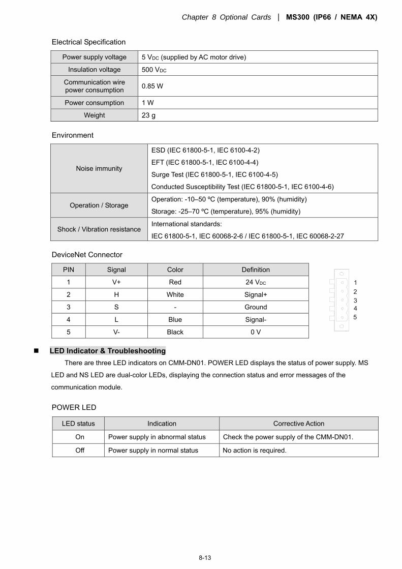
Chapter 8 Optional Cards MS300 (IP66 / NEMA 4X)
8-13
Electrical Specification
Power supply voltage 5 VDC (supplied by AC motor drive)
Insulation voltage 500 VDC
Communication wire power consumption 0.85 W
Power consumption 1 W
Weight 23 g
Environment
Noise immunity
ESD (IEC 61800-5-1, IEC 6100-4-2)
EFT (IEC 61800-5-1, IEC 6100-4-4)
Surge Test (IEC 61800-5-1, IEC 6100-4-5)
Conducted Susceptibility Test (IEC 61800-5-1, IEC 6100-4-6)
Operation / Storage Operation: -10–50 ºC (temperature), 90% (humidity)
Storage: -25–70 ºC (temperature), 95% (humidity)
Shock / Vibration resistance International standards:
IEC 61800-5-1, IEC 60068-2-6 / IEC 61800-5-1, IEC 60068-2-27
DeviceNet Connector
PIN Signal Color Definition
54321
1 V+ Red 24 VDC
2 H White Signal+
3 S - Ground
4 L Blue Signal-
5 V- Black 0 V
LED Indicator & Troubleshooting
There are three LED indicators on CMM-DN01. POWER LED displays the status of power supply. MS
LED and NS LED are dual-color LEDs, displaying the connection status and error messages of the
communication module.
POWER LED
LED status Indication Corrective Action
On Power supply in abnormal status Check the power supply of the CMM-DN01.
Off Power supply in normal status No action is required.
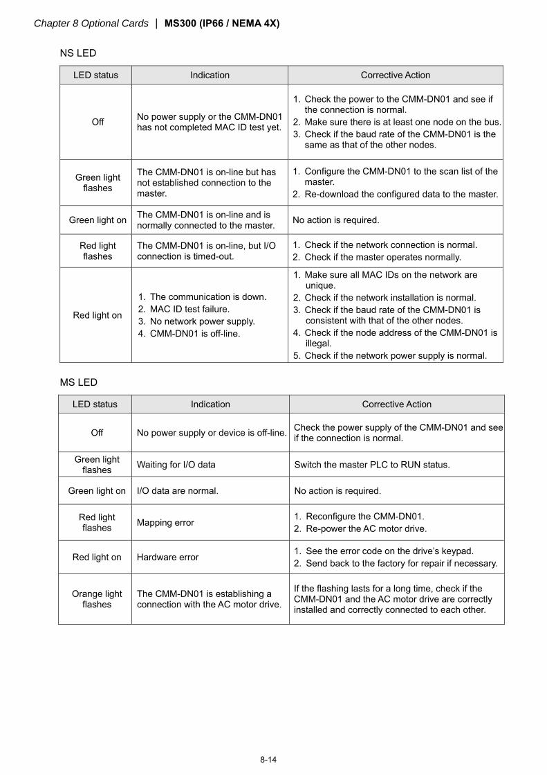
Chapter 8 Optional Cards MS300 (IP66 / NEMA 4X)
8-14
NS LED
LED status Indication Corrective Action
Off No power supply or the CMM-DN01 has not completed MAC ID test yet.
1. Check the power to the CMM-DN01 and see if the connection is normal.
2. Make sure there is at least one node on the bus. 3. Check if the baud rate of the CMM-DN01 is the
same as that of the other nodes.
Green light flashes
The CMM-DN01 is on-line but has not established connection to the master.
1. Configure the CMM-DN01 to the scan list of the master.
2. Re-download the configured data to the master.
Green light on The CMM-DN01 is on-line and is normally connected to the master. No action is required.
Red light flashes
The CMM-DN01 is on-line, but I/O connection is timed-out.
1. Check if the network connection is normal. 2. Check if the master operates normally.
Red light on
1. The communication is down. 2. MAC ID test failure. 3. No network power supply. 4. CMM-DN01 is off-line.
1. Make sure all MAC IDs on the network are unique.
2. Check if the network installation is normal. 3. Check if the baud rate of the CMM-DN01 is
consistent with that of the other nodes. 4. Check if the node address of the CMM-DN01 is
illegal. 5. Check if the network power supply is normal.
MS LED
LED status Indication Corrective Action
Off No power supply or device is off-line. Check the power supply of the CMM-DN01 and see if the connection is normal.
Green light flashes Waiting for I/O data Switch the master PLC to RUN status.
Green light on I/O data are normal. No action is required.
Red light flashes Mapping error 1. Reconfigure the CMM-DN01.
2. Re-power the AC motor drive.
Red light on Hardware error 1. See the error code on the drive’s keypad. 2. Send back to the factory for repair if necessary.
Orange light flashes
The CMM-DN01 is establishing a connection with the AC motor drive.
If the flashing lasts for a long time, check if the CMM-DN01 and the AC motor drive are correctly installed and correctly connected to each other.
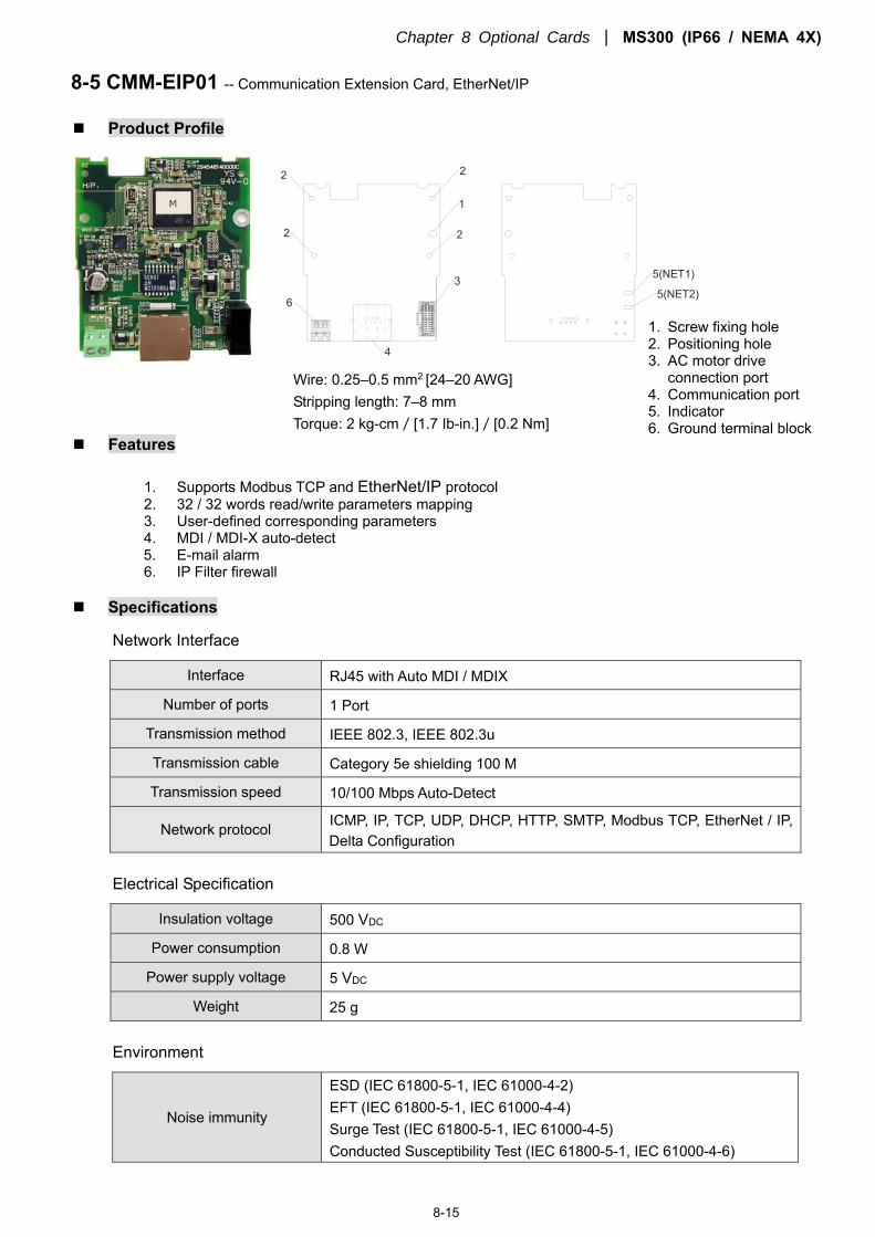
Chapter 8 Optional Cards MS300 (IP66 / NEMA 4X)
8-15
8-5 CMM-EIP01 -- Communication Extension Card, EtherNet/IP
Product Profile
5(NET2)
5(NET1)
6
2
4
3
2 2
2
1
Features
1. Supports Modbus TCP and EtherNet/IP protocol 2. 32 / 32 words read/write parameters mapping 3. User-defined corresponding parameters 4. MDI / MDI-X auto-detect 5. E-mail alarm 6. IP Filter firewall
Specifications
Network Interface
Interface RJ45 with Auto MDI / MDIX
Number of ports 1 Port
Transmission method IEEE 802.3, IEEE 802.3u
Transmission cable Category 5e shielding 100 M
Transmission speed 10/100 Mbps Auto-Detect
Network protocol ICMP, IP, TCP, UDP, DHCP, HTTP, SMTP, Modbus TCP, EtherNet / IP, Delta Configuration
Electrical Specification
Insulation voltage 500 VDC
Power consumption 0.8 W
Power supply voltage 5 VDC
Weight 25 g
Environment
Noise immunity
ESD (IEC 61800-5-1, IEC 61000-4-2) EFT (IEC 61800-5-1, IEC 61000-4-4) Surge Test (IEC 61800-5-1, IEC 61000-4-5) Conducted Susceptibility Test (IEC 61800-5-1, IEC 61000-4-6)
Wire: 0.25–0.5 mm2 [24–20 AWG] Stripping length: 7–8 mm Torque: 2 kg-cm/[1.7 Ib-in.]/[0.2 Nm]
1. Screw fixing hole 2. Positioning hole 3. AC motor drive
connection port 4. Communication port 5. Indicator 6. Ground terminal block
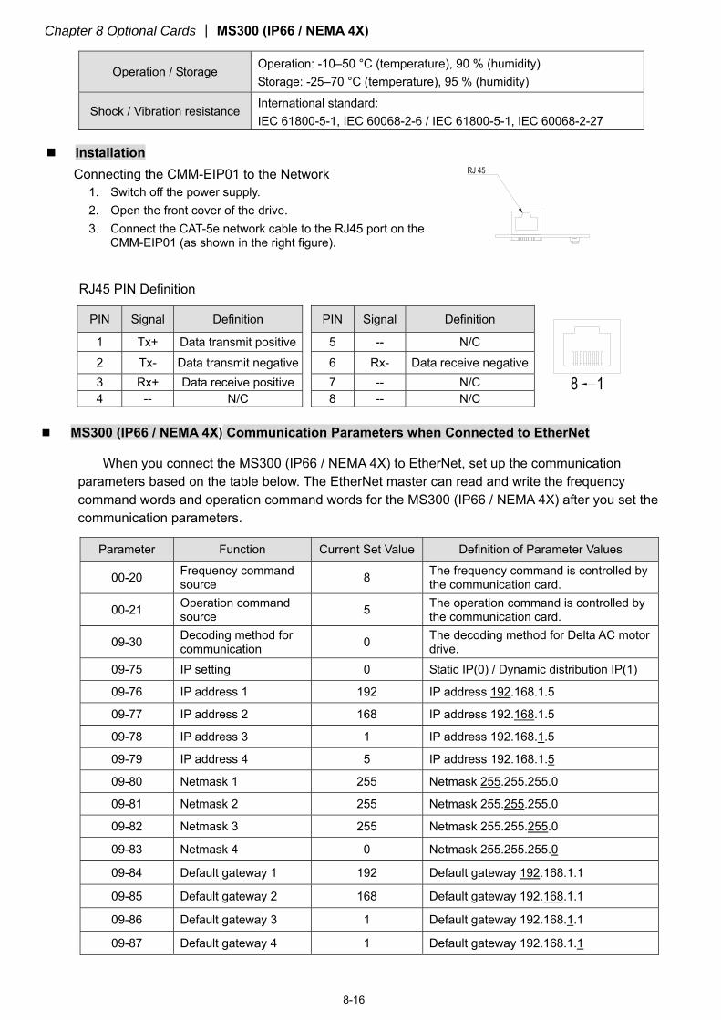
Chapter 8 Optional Cards MS300 (IP66 / NEMA 4X)
8-16
Operation / Storage Operation: -10–50 °C (temperature), 90 % (humidity) Storage: -25–70 °C (temperature), 95 % (humidity)
Shock / Vibration resistance International standard: IEC 61800-5-1, IEC 60068-2-6 / IEC 61800-5-1, IEC 60068-2-27
Installation
Connecting the CMM-EIP01 to the Network 1. Switch off the power supply. 2. Open the front cover of the drive. 3. Connect the CAT-5e network cable to the RJ45 port on the
CMM-EIP01 (as shown in the right figure).
RJ45 PIN Definition
PIN Signal Definition PIN Signal Definition
1 Tx+ Data transmit positive 5 -- N/C 2 Tx- Data transmit negative 6 Rx- Data receive negative 3 Rx+ Data receive positive 7 -- N/C 4 -- N/C 8 -- N/C
MS300 (IP66 / NEMA 4X) Communication Parameters when Connected to EtherNet
When you connect the MS300 (IP66 / NEMA 4X) to EtherNet, set up the communication parameters based on the table below. The EtherNet master can read and write the frequency command words and operation command words for the MS300 (IP66 / NEMA 4X) after you set the communication parameters.
Parameter Function Current Set Value Definition of Parameter Values
00-20 Frequency command source 8 The frequency command is controlled by
the communication card.
00-21 Operation command source 5 The operation command is controlled by
the communication card.
09-30 Decoding method for communication 0 The decoding method for Delta AC motor
drive. 09-75 IP setting 0 Static IP(0) / Dynamic distribution IP(1)
09-76 IP address 1 192 IP address 192.168.1.5
09-77 IP address 2 168 IP address 192.168.1.5
09-78 IP address 3 1 IP address 192.168.1.5
09-79 IP address 4 5 IP address 192.168.1.5
09-80 Netmask 1 255 Netmask 255.255.255.0
09-81 Netmask 2 255 Netmask 255.255.255.0
09-82 Netmask 3 255 Netmask 255.255.255.0
09-83 Netmask 4 0 Netmask 255.255.255.0
09-84 Default gateway 1 192 Default gateway 192.168.1.1
09-85 Default gateway 2 168 Default gateway 192.168.1.1
09-86 Default gateway 3 1 Default gateway 192.168.1.1
09-87 Default gateway 4 1 Default gateway 192.168.1.1
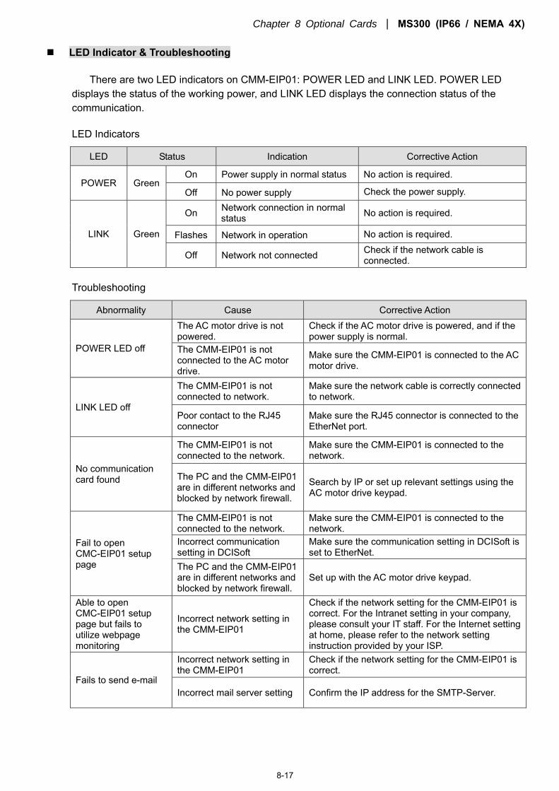
Chapter 8 Optional Cards MS300 (IP66 / NEMA 4X)
8-17
LED Indicator & Troubleshooting
There are two LED indicators on CMM-EIP01: POWER LED and LINK LED. POWER LED displays the status of the working power, and LINK LED displays the connection status of the communication.
LED Indicators
LED Status Indication Corrective Action
POWER Green On Power supply in normal status No action is required.
Off No power supply Check the power supply.
LINK Green
On Network connection in normal status No action is required.
Flashes Network in operation No action is required.
Off Network not connected Check if the network cable is connected.
Troubleshooting
Abnormality Cause Corrective Action
POWER LED off
The AC motor drive is not powered.
Check if the AC motor drive is powered, and if the power supply is normal.
The CMM-EIP01 is not connected to the AC motor drive.
Make sure the CMM-EIP01 is connected to the AC motor drive.
LINK LED off
The CMM-EIP01 is not connected to network.
Make sure the network cable is correctly connected to network.
Poor contact to the RJ45 connector
Make sure the RJ45 connector is connected to the EtherNet port.
No communication card found
The CMM-EIP01 is not connected to the network.
Make sure the CMM-EIP01 is connected to the network.
The PC and the CMM-EIP01 are in different networks and blocked by network firewall.
Search by IP or set up relevant settings using the AC motor drive keypad.
Fail to open CMC-EIP01 setup page
The CMM-EIP01 is not connected to the network.
Make sure the CMM-EIP01 is connected to the network.
Incorrect communication setting in DCISoft
Make sure the communication setting in DCISoft is set to EtherNet.
The PC and the CMM-EIP01 are in different networks and blocked by network firewall.
Set up with the AC motor drive keypad.
Able to open CMC-EIP01 setup page but fails to utilize webpage monitoring
Incorrect network setting in the CMM-EIP01
Check if the network setting for the CMM-EIP01 is correct. For the Intranet setting in your company, please consult your IT staff. For the Internet setting at home, please refer to the network setting instruction provided by your ISP.
Fails to send e-mail
Incorrect network setting in the CMM-EIP01
Check if the network setting for the CMM-EIP01 is correct.
Incorrect mail server setting Confirm the IP address for the SMTP-Server.
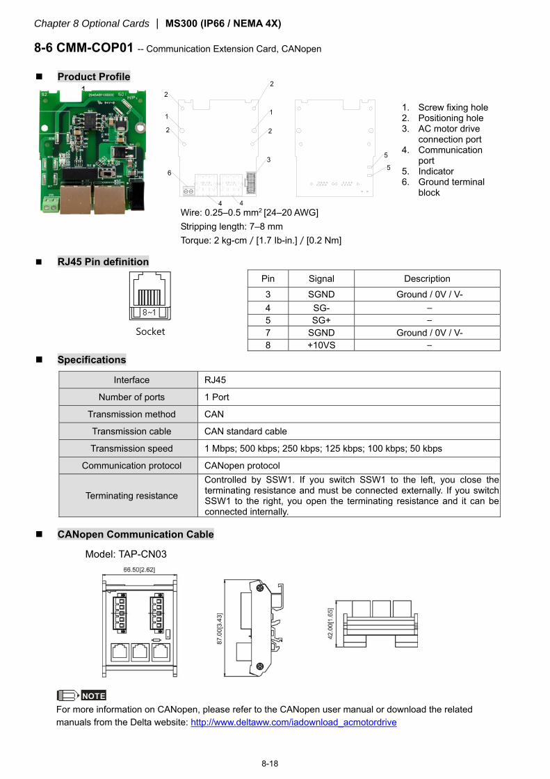
Chapter 8 Optional Cards MS300 (IP66 / NEMA 4X)
8-18
8-6 CMM-COP01 -- Communication Extension Card, CANopen
Product Profile 1.
RJ45 Pin definition
Socket
Pin Signal Description 3 SGND Ground / 0V / V- 4 SG- – 5 SG+ – 7 SGND Ground / 0V / V-
8 +10VS – Specifications
Interface RJ45
Number of ports 1 Port
Transmission method CAN
Transmission cable CAN standard cable
Transmission speed 1 Mbps; 500 kbps; 250 kbps; 125 kbps; 100 kbps; 50 kbps
Communication protocol CANopen protocol
Terminating resistance
Controlled by SSW1. If you switch SSW1 to the left, you close the terminating resistance and must be connected externally. If you switch SSW1 to the right, you open the terminating resistance and it can be connected internally.
CANopen Communication Cable
Model: TAP-CN03
NOTE For more information on CANopen, please refer to the CANopen user manual or download the related manuals from the Delta website: http://www.deltaww.com/iadownload_acmotordrive
Wire: 0.25–0.5 mm2 [24–20 AWG] Stripping length: 7–8 mm Torque: 2 kg-cm/[1.7 Ib-in.]/[0.2 Nm]
1. Screw fixing hole 2. Positioning hole 3. AC motor drive
connection port 4. Communication
port 5. Indicator 6. Ground terminal
block

Chapter 8 Optional Cards MS300 (IP66 / NEMA 4X)
8-19
8-7 EMM-BPS01 -- +24 V Power Extension Card
Product Profile
2
3
1
4
2
3
2
1. Screw fixing hole
2. Positioning hole 3. AC motor drive
connection port 4. +24 V terminal
block
Features
1. Provides external power supply. 2. Supports external 24 VDC input. 3. Supports reading and writing parameter and status monitoring of the drive.
Specifications
When the drive is only powered by the EMC-BPS01, communication remains normal, including support for all
communication cards and the following functions:
Reading and writing parameters
Display with keypad
Keypad buttons (except the RUN button)
Analog input, can be used with +10 V terminal to supply the power.
Multi-function inputs (FWD, REV, MI1–MI8), can be used with +24 V terminal or an external power
supply.
Relay output available
Pulse sequence frequency command function
The following functions are not supported:
DFM digital frequency signal output
AFM multi-function analog voltage output
PLC function
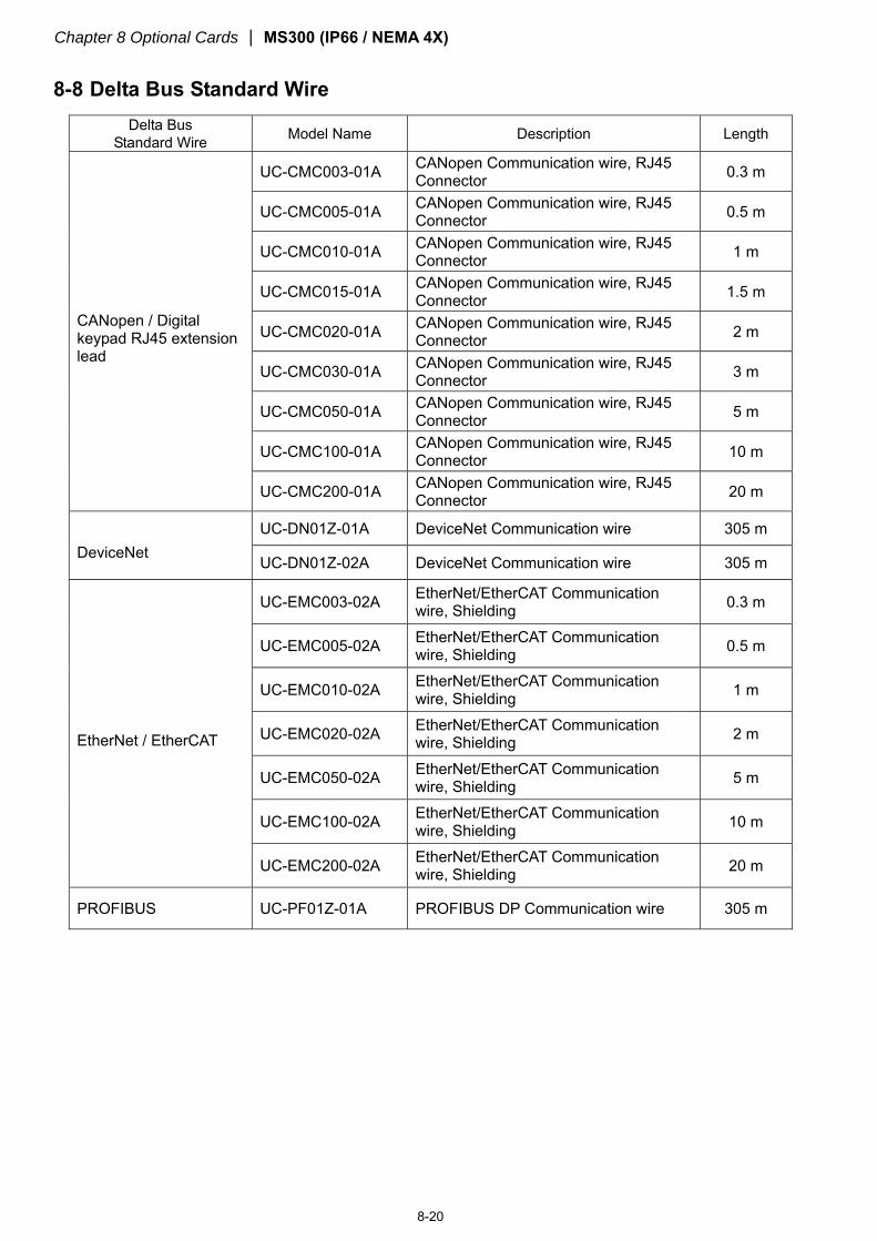
Chapter 8 Optional Cards MS300 (IP66 / NEMA 4X)
8-20
8-8 Delta Bus Standard Wire
Delta Bus Standard Wire Model Name Description Length
CANopen / Digital keypad RJ45 extension lead
UC-CMC003-01A CANopen Communication wire, RJ45 Connector 0.3 m
UC-CMC005-01A CANopen Communication wire, RJ45 Connector 0.5 m
UC-CMC010-01A CANopen Communication wire, RJ45 Connector 1 m
UC-CMC015-01A CANopen Communication wire, RJ45 Connector 1.5 m
UC-CMC020-01A CANopen Communication wire, RJ45 Connector 2 m
UC-CMC030-01A CANopen Communication wire, RJ45 Connector 3 m
UC-CMC050-01A CANopen Communication wire, RJ45 Connector 5 m
UC-CMC100-01A CANopen Communication wire, RJ45 Connector 10 m
UC-CMC200-01A CANopen Communication wire, RJ45 Connector 20 m
DeviceNet UC-DN01Z-01A DeviceNet Communication wire 305 m
UC-DN01Z-02A DeviceNet Communication wire 305 m
EtherNet / EtherCAT
UC-EMC003-02A EtherNet/EtherCAT Communication wire, Shielding 0.3 m
UC-EMC005-02A EtherNet/EtherCAT Communication wire, Shielding 0.5 m
UC-EMC010-02A EtherNet/EtherCAT Communication wire, Shielding 1 m
UC-EMC020-02A EtherNet/EtherCAT Communication wire, Shielding 2 m
UC-EMC050-02A EtherNet/EtherCAT Communication wire, Shielding 5 m
UC-EMC100-02A EtherNet/EtherCAT Communication wire, Shielding 10 m
UC-EMC200-02A EtherNet/EtherCAT Communication wire, Shielding 20 m
PROFIBUS UC-PF01Z-01A PROFIBUS DP Communication wire 305 m
Chapter 9 Specification MS300 (IP66 / NEMA 4X)
9-1
Chapter 9 Specification
9-1 230V Series
9-2 460V Series
9-3 Environment for Operation, Storage and Transportation
9-4 Derating for Ambient Temperature and Altitude
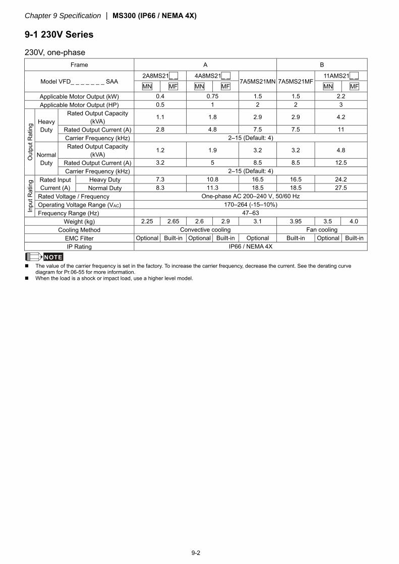
Chapter 9 Specification MS300 (IP66 / NEMA 4X)
9-2
9-1 230V Series
230V, one-phase Frame A B
Model VFD_ _ _ _ _ _ _ SAA 2A8MS21_ _ 4A8MS21_ _
7A5MS21MN 7A5MS21MF 11AMS21_ _
MN MF MN MF MN MF Applicable Motor Output (kW) 0.4 0.75 1.5 1.5 2.2 Applicable Motor Output (HP) 0.5 1 2 2 3
Out
put R
atin
g Heavy Duty
Rated Output Capacity (kVA)
1.1 1.8 2.9 2.9 4.2
Rated Output Current (A) 2.8 4.8 7.5 7.5 11 Carrier Frequency (kHz) 2–15 (Default: 4)
Normal Duty
Rated Output Capacity (kVA)
1.2 1.9 3.2 3.2 4.8
Rated Output Current (A) 3.2 5 8.5 8.5 12.5 Carrier Frequency (kHz) 2–15 (Default: 4)
Inpu
t Rat
ing Rated Input
Current (A) Heavy Duty 7.3 10.8 16.5 16.5 24.2 Normal Duty 8.3 11.3 18.5 18.5 27.5
Rated Voltage / Frequency One-phase AC 200–240 V, 50/60 Hz Operating Voltage Range (VAC) 170–264 (-15–10%) Frequency Range (Hz) 47–63
Weight (kg) 2.25 2.65 2.6 2.9 3.1 3.95 3.5 4.0 Cooling Method Convective cooling Fan cooling
EMC Filter Optional Built-in Optional Built-in Optional Built-in Optional Built-in IP Rating IP66 / NEMA 4X
NOTE The value of the carrier frequency is set in the factory. To increase the carrier frequency, decrease the current. See the derating curve
diagram for Pr.06-55 for more information. When the load is a shock or impact load, use a higher level model.
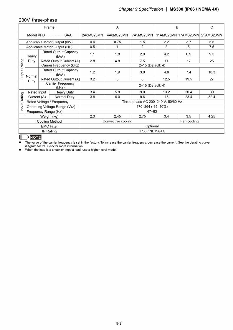
Chapter 9 Specification MS300 (IP66 / NEMA 4X)
9-3
230V, three-phase Frame A B C
Model VFD_ _ _ _ _ _ _SAA 2A8MS23MN 4A8MS23MN 7A5MS23MN 11AMS23MN 17AMS23MN 25AMS23MN
Applicable Motor Output (kW) 0.4 0.75 1.5 2.2 3.7 5.5 Applicable Motor Output (HP) 0.5 1 2 3 5 7.5
Out
put R
atin
g
Heavy Duty
Rated Output Capacity (kVA)
1.1 1.8 2.9 4.2 6.5 9.5
Rated Output Current (A) 2.8 4.8 7.5 11 17 25 Carrier Frequency (kHz) 2–15 (Default: 4)
Normal Duty
Rated Output Capacity (kVA)
1.2 1.9 3.0 4.8 7.4 10.3
Rated Output Current (A) 3.2 5 8 12.5 19.5 27 Carrier Frequency
(kHz) 2–15 (Default: 4)
Inpu
t Rat
ing Rated Input
Current (A) Heavy Duty 3.4 5.8 9.0 13.2 20.4 30 Normal Duty 3.8 6.0 9.6 15 23.4 32.4
Rated Voltage / Frequency Three-phase AC 200–240 V, 50/60 Hz Operating Voltage Range (VAC) 170–264 (-15–10%) Frequency Range (Hz) 47–63
Weight (kg) 2.3 2.45 2.75 3.4 3.5 4.25 Cooling Method Convective cooling Fan cooling
EMC Filter Optional IP Rating IP66 / NEMA 4X
NOTE The value of the carrier frequency is set in the factory. To increase the carrier frequency, decrease the current. See the derating curve
diagram for Pr.06-55 for more information. When the load is a shock or impact load, use a higher level model.
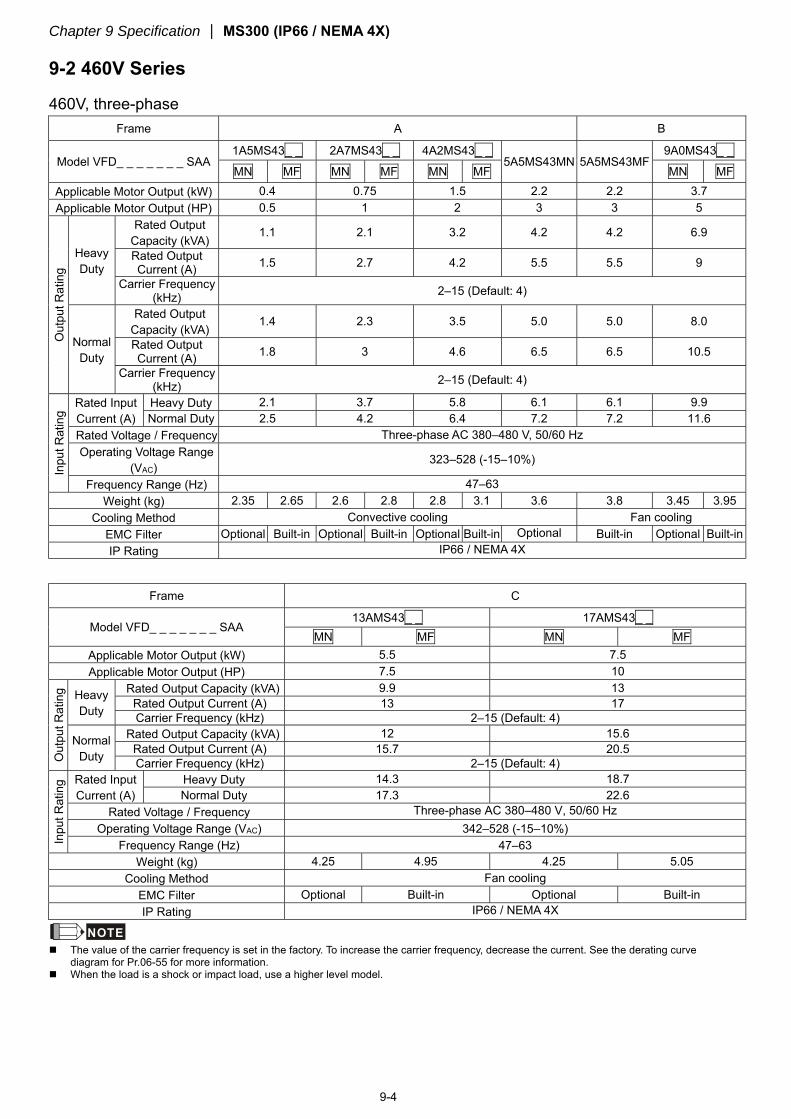
Chapter 9 Specification MS300 (IP66 / NEMA 4X)
9-4
9-2 460V Series
460V, three-phase Frame A B
Model VFD_ _ _ _ _ _ _ SAA 1A5MS43_ _ 2A7MS43_ _ 4A2MS43_ _
5A5MS43MN 5A5MS43MF 9A0MS43_ _
MN MF MN MF MN MF MN MF Applicable Motor Output (kW) 0.4 0.75 1.5 2.2 2.2 3.7 Applicable Motor Output (HP) 0.5 1 2 3 3 5
Out
put R
atin
g
Heavy Duty
Rated Output Capacity (kVA)
1.1 2.1 3.2 4.2 4.2 6.9
Rated Output Current (A) 1.5 2.7 4.2 5.5 5.5 9
Carrier Frequency (kHz) 2–15 (Default: 4)
Normal Duty
Rated Output Capacity (kVA)
1.4 2.3 3.5 5.0 5.0 8.0
Rated Output Current (A) 1.8 3 4.6 6.5 6.5 10.5
Carrier Frequency (kHz) 2–15 (Default: 4)
Inpu
t Rat
ing
Rated Input Current (A)
Heavy Duty 2.1 3.7 5.8 6.1 6.1 9.9 Normal Duty 2.5 4.2 6.4 7.2 7.2 11.6
Rated Voltage / Frequency Three-phase AC 380–480 V, 50/60 Hz Operating Voltage Range
(VAC) 323–528 (-15–10%)
Frequency Range (Hz) 47–63 Weight (kg) 2.35 2.65 2.6 2.8 2.8 3.1 3.6 3.8 3.45 3.95
Cooling Method Convective cooling Fan cooling EMC Filter Optional Built-in Optional Built-in Optional Built-in Optional Built-in Optional Built-in IP Rating IP66 / NEMA 4X
Frame C
Model VFD_ _ _ _ _ _ _ SAA 13AMS43_ _ 17AMS43_ _
MN MF MN MF Applicable Motor Output (kW) 5.5 7.5 Applicable Motor Output (HP) 7.5 10
Out
put R
atin
g Heavy Duty
Rated Output Capacity (kVA) 9.9 13 Rated Output Current (A) 13 17 Carrier Frequency (kHz) 2–15 (Default: 4)
Normal Duty
Rated Output Capacity (kVA) 12 15.6 Rated Output Current (A) 15.7 20.5 Carrier Frequency (kHz) 2–15 (Default: 4)
Inpu
t Rat
ing Rated Input
Current (A) Heavy Duty 14.3 18.7 Normal Duty 17.3 22.6
Rated Voltage / Frequency Three-phase AC 380–480 V, 50/60 Hz Operating Voltage Range (VAC) 342–528 (-15–10%)
Frequency Range (Hz) 47–63 Weight (kg) 4.25 4.95 4.25 5.05
Cooling Method Fan cooling EMC Filter Optional Built-in Optional Built-in IP Rating IP66 / NEMA 4X
NOTE The value of the carrier frequency is set in the factory. To increase the carrier frequency, decrease the current. See the derating curve
diagram for Pr.06-55 for more information. When the load is a shock or impact load, use a higher level model.
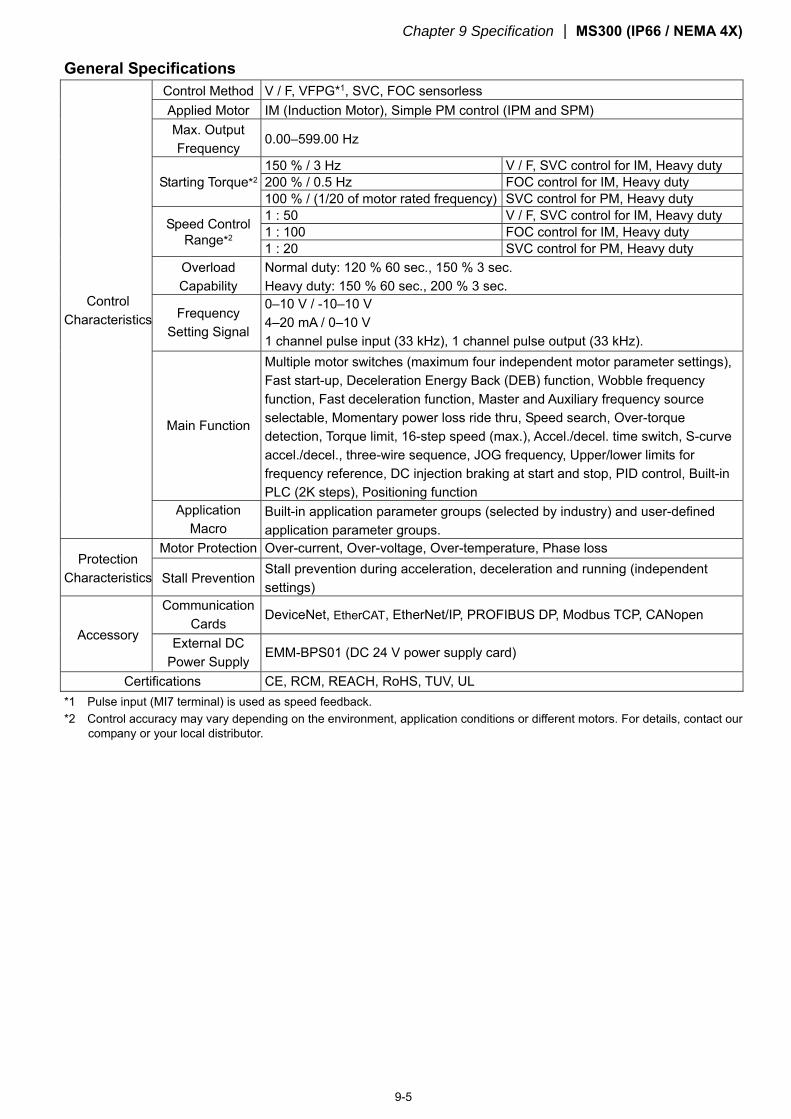
Chapter 9 Specification MS300 (IP66 / NEMA 4X)
9-5
General Specifications
Control Characteristics
Control Method V / F, VFPG*1, SVC, FOC sensorless Applied Motor IM (Induction Motor), Simple PM control (IPM and SPM) Max. Output Frequency
0.00–599.00 Hz
Starting Torque*2 150 % / 3 Hz V / F, SVC control for IM, Heavy duty 200 % / 0.5 Hz FOC control for IM, Heavy duty 100 % / (1/20 of motor rated frequency) SVC control for PM, Heavy duty
Speed Control Range*2
1 : 50 V / F, SVC control for IM, Heavy duty 1 : 100 FOC control for IM, Heavy duty 1 : 20 SVC control for PM, Heavy duty
Overload Capability
Normal duty: 120 % 60 sec., 150 % 3 sec. Heavy duty: 150 % 60 sec., 200 % 3 sec.
Frequency Setting Signal
0–10 V / -10–10 V 4–20 mA / 0–10 V 1 channel pulse input (33 kHz), 1 channel pulse output (33 kHz).
Main Function
Multiple motor switches (maximum four independent motor parameter settings), Fast start-up, Deceleration Energy Back (DEB) function, Wobble frequency function, Fast deceleration function, Master and Auxiliary frequency source selectable, Momentary power loss ride thru, Speed search, Over-torque detection, Torque limit, 16-step speed (max.), Accel./decel. time switch, S-curve accel./decel., three-wire sequence, JOG frequency, Upper/lower limits for frequency reference, DC injection braking at start and stop, PID control, Built-in PLC (2K steps), Positioning function
Application Macro
Built-in application parameter groups (selected by industry) and user-defined application parameter groups.
Protection Characteristics
Motor Protection Over-current, Over-voltage, Over-temperature, Phase loss
Stall Prevention Stall prevention during acceleration, deceleration and running (independent settings)
Accessory
Communication Cards
DeviceNet, EtherCAT, EtherNet/IP, PROFIBUS DP, Modbus TCP, CANopen
External DC Power Supply
EMM-BPS01 (DC 24 V power supply card)
Certifications CE, RCM, REACH, RoHS, TUV, UL *1 Pulse input (MI7 terminal) is used as speed feedback. *2 Control accuracy may vary depending on the environment, application conditions or different motors. For details, contact our
company or your local distributor.
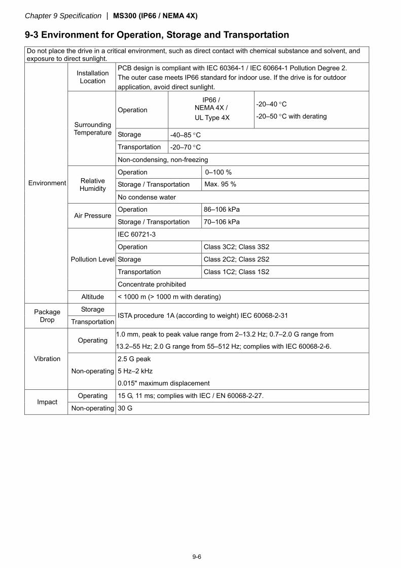
Chapter 9 Specification MS300 (IP66 / NEMA 4X)
9-6
9-3 Environment for Operation, Storage and Transportation
Do not place the drive in a critical environment, such as direct contact with chemical substance and solvent, and exposure to direct sunlight.
Environment
Installation Location
PCB design is compliant with IEC 60364-1 / IEC 60664-1 Pollution Degree 2. The outer case meets IP66 standard for indoor use. If the drive is for outdoor application, avoid direct sunlight.
Surrounding Temperature
Operation IP66 /
NEMA 4X / UL Type 4X
-20–40 C
-20–50 C with derating
Storage -40–85 C
Transportation -20–70 C
Non-condensing, non-freezing
Relative Humidity
Operation 0–100 %
Storage / Transportation Max. 95 %
No condense water
Air Pressure Operation 86–106 kPa
Storage / Transportation 70–106 kPa
Pollution Level
IEC 60721-3
Operation Class 3C2; Class 3S2
Storage Class 2C2; Class 2S2
Transportation Class 1C2; Class 1S2
Concentrate prohibited
Altitude < 1000 m (> 1000 m with derating)
Package Drop
Storage ISTA procedure 1A (according to weight) IEC 60068-2-31
Transportation
Vibration
Operating 1.0 mm, peak to peak value range from 2–13.2 Hz; 0.7–2.0 G range from
13.2–55 Hz; 2.0 G range from 55–512 Hz; complies with IEC 60068-2-6.
Non-operating
2.5 G peak
5 Hz–2 kHz
0.015" maximum displacement
Impact Operating 15 G, 11 ms; complies with IEC / EN 60068-2-27.
Non-operating 30 G
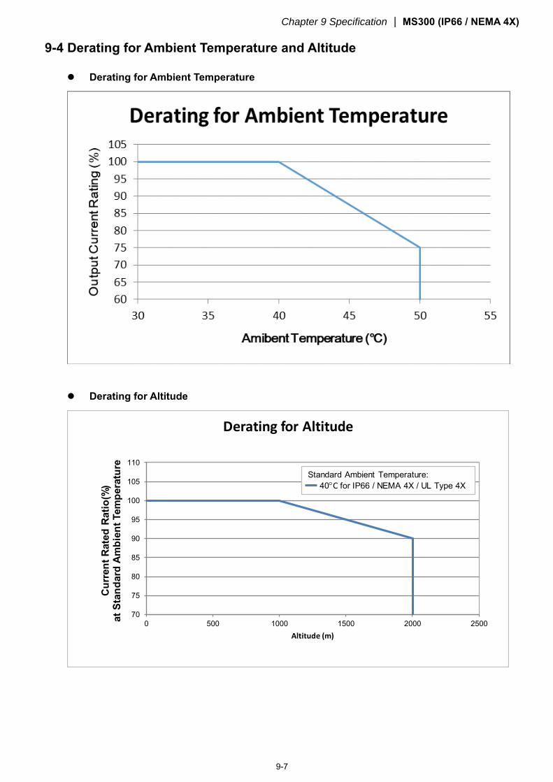
Chapter 9 Specification MS300 (IP66 / NEMA 4X)
9-7
9-4 Derating for Ambient Temperature and Altitude Derating for Ambient Temperature
Derating for Altitude
70
75
80
85
90
95
100
105
110
0 500 1000 1500 2000 2500
Cu
rren
t R
ated
Rat
io(%
) at
Sta
nd
ard
Am
bie
nt
Tem
per
atu
re
Altitude (m)
Derating for Altitude
Standard Ambient Temperature:40C for IP66 / NEMA 4X / UL Type 4X
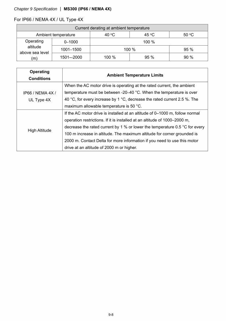
Chapter 9 Specification MS300 (IP66 / NEMA 4X)
9-8
For IP66 / NEMA 4X / UL Type 4X
Current derating at ambient temperature Ambient temperature 40 oC 45 oC 50 oC
Operating altitude
above sea level (m)
0–1000 100 %
1001–1500 100 % 95 %
1501-–2000 100 % 95 % 90 %
Operating
Conditions Ambient Temperature Limits
IP66 / NEMA 4X / UL Type 4X
When the AC motor drive is operating at the rated current, the ambient temperature must be between -20–40 °C. When the temperature is over 40 °C, for every increase by 1 °C, decrease the rated current 2.5 %. The maximum allowable temperature is 50 °C.
High Altitude
If the AC motor drive is installed at an altitude of 0–1000 m, follow normal operation restrictions. If it is installed at an altitude of 1000–2000 m, decrease the rated current by 1 % or lower the temperature 0.5 °C for every 100 m increase in altitude. The maximum altitude for corner grounded is 2000 m. Contact Delta for more information if you need to use this motor drive at an altitude of 2000 m or higher.
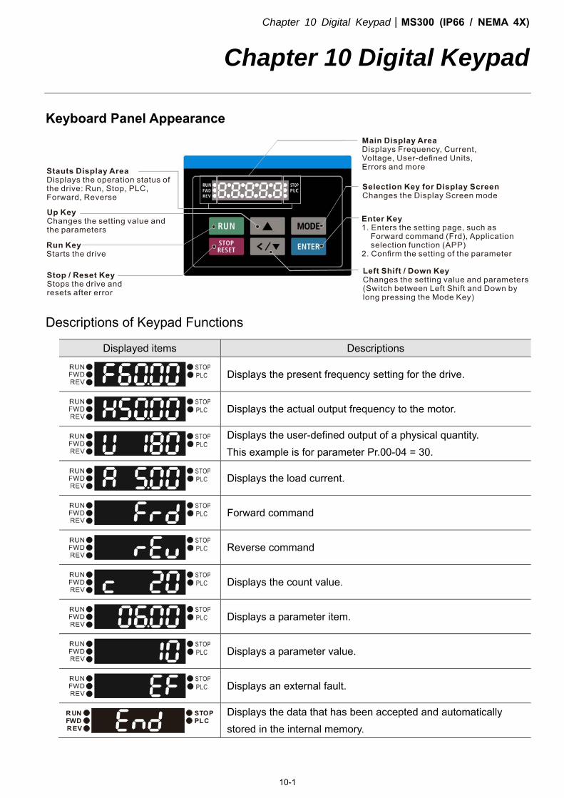
Chapter 10 Digital KeypadMS300 (IP66 / NEMA 4X)
10-1
Chapter 10 Digital Keypad
Keyboard Panel Appearance
Descriptions of Keypad Functions
Displayed items Descriptions
Displays the present frequency setting for the drive.
Displays the actual output frequency to the motor.
Displays the user-defined output of a physical quantity. This example is for parameter Pr.00-04 = 30.
Displays the load current.
Forward command
Reverse command
Displays the count value.
Displays a parameter item.
Displays a parameter value.
Displays an external fault.
RUNFWDREV
STOPPLC
Displays the data that has been accepted and automatically stored in the internal memory.
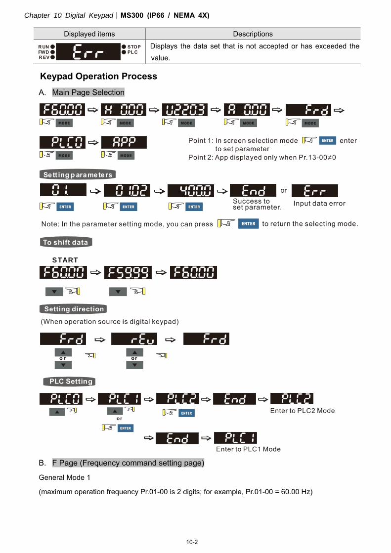
Chapter 10 Digital KeypadMS300 (IP66 / NEMA 4X)
10-2
Displayed items Descriptions RUNFWDREV
STOPPLC
Displays the data set that is not accepted or has exceeded the value.
Keypad Operation Process
A. Main Page Selection
Sett ing p arameters
or
START
o r or
PLC Setting
or
B. F Page (Frequency command setting page)
General Mode 1
(maximum operation frequency Pr.01-00 is 2 digits; for example, Pr.01-00 = 60.00 Hz)
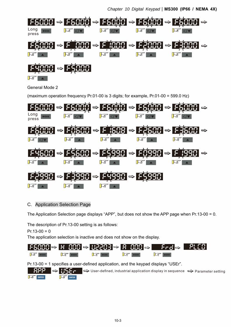
Chapter 10 Digital KeypadMS300 (IP66 / NEMA 4X)
10-3
General Mode 2
(maximum operation frequency Pr.01-00 is 3 digits; for example, Pr.01-00 = 599.0 Hz)
C. Application Selection Page
The Application Selection page displays “APP”, but does not show the APP page when Pr.13-00 = 0.
The description of Pr.13-00 setting is as follows: Pr.13-00 = 0 The application selection is inactive and does not show on the display.
Pr.13-00 = 1 specifies a user-defined application, and the keypad displays “USEr”.
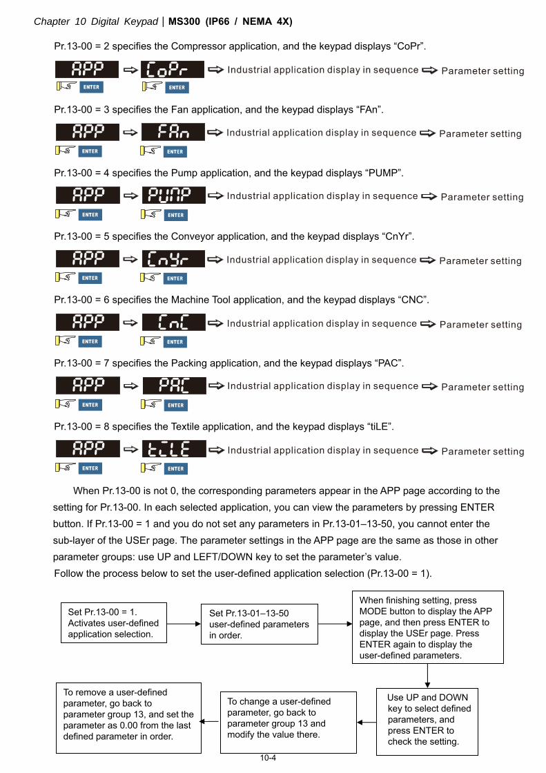
Chapter 10 Digital KeypadMS300 (IP66 / NEMA 4X)
10-4
Pr.13-00 = 2 specifies the Compressor application, and the keypad displays “CoPr”.
Pr.13-00 = 3 specifies the Fan application, and the keypad displays “FAn”.
Pr.13-00 = 4 specifies the Pump application, and the keypad displays “PUMP”.
Pr.13-00 = 5 specifies the Conveyor application, and the keypad displays “CnYr”.
Pr.13-00 = 6 specifies the Machine Tool application, and the keypad displays “CNC”.
Pr.13-00 = 7 specifies the Packing application, and the keypad displays “PAC”.
Pr.13-00 = 8 specifies the Textile application, and the keypad displays “tiLE”.
When Pr.13-00 is not 0, the corresponding parameters appear in the APP page according to the setting for Pr.13-00. In each selected application, you can view the parameters by pressing ENTER button. If Pr.13-00 = 1 and you do not set any parameters in Pr.13-01–13-50, you cannot enter the sub-layer of the USEr page. The parameter settings in the APP page are the same as those in other parameter groups: use UP and LEFT/DOWN key to set the parameter’s value. Follow the process below to set the user-defined application selection (Pr.13-00 = 1).
Set Pr.13-00 = 1. Activates user-defined application selection.
Set Pr.13-01–13-50 user-defined parameters in order.
When finishing setting, press MODE button to display the APP page, and then press ENTER to display the USEr page. Press ENTER again to display the user-defined parameters.
Use UP and DOWN key to select defined parameters, and press ENTER to check the setting.
To change a user-defined parameter, go back to parameter group 13 and modify the value there.
To remove a user-defined parameter, go back to parameter group 13, and set the parameter as 0.00 from the last defined parameter in order.
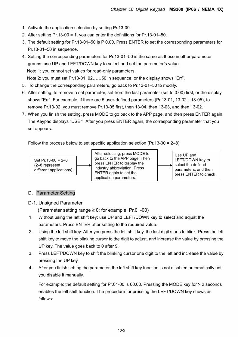
Chapter 10 Digital KeypadMS300 (IP66 / NEMA 4X)
10-5
1. Activate the application selection by setting Pr.13-00. 2. After setting Pr.13-00 = 1, you can enter the definitions for Pr.13-01–50. 3. The default setting for Pr.13-01–50 is P 0.00. Press ENTER to set the corresponding parameters for
Pr.13-01–50 in sequence. 4. Setting the corresponding parameters for Pr.13-01–50 is the same as those in other parameter
groups: use UP and LEFT/DOWN key to select and set the parameter’s value. Note 1: you cannot set values for read-only parameters. Note 2: you must set Pr.13-01, 02……50 in sequence, or the display shows “Err”.
5. To change the corresponding parameters, go back to Pr.13-01–50 to modify. 6. After setting, to remove a set parameter, set from the last parameter (set to 0.00) first, or the display
shows “Err”. For example, if there are 5 user-defined parameters (Pr.13-01, 13-02…13-05), to remove Pr.13-02, you must remove Pr.13-05 first, then 13-04, then 13-03, and then 13-02.
7. When you finish the setting, press MODE to go back to the APP page, and then press ENTER again. The Keypad displays “USEr”. After you press ENTER again, the corresponding parameter that you set appears. Follow the process below to set specific application selection (Pr.13-00 = 2–8).
D. Parameter Setting
D-1. Unsigned Parameter (Parameter setting range ≥ 0; for example: Pr.01-00)
1. Without using the left shift key: use UP and LEFT/DOWN key to select and adjust the parameters. Press ENTER after setting to the required value.
2. Using the left shift key: After you press the left shift key, the last digit starts to blink. Press the left shift key to move the blinking cursor to the digit to adjust, and increase the value by pressing the UP key. The value goes back to 0 after 9.
3. Press LEFT/DOWN key to shift the blinking cursor one digit to the left and increase the value by pressing the UP key.
4. After you finish setting the parameter, the left shift key function is not disabled automatically until you disable it manually.
For example: the default setting for Pr.01-00 is 60.00. Pressing the MODE key for > 2 seconds enables the left shift function. The procedure for pressing the LEFT/DOWN key shows as follows:
Set Pr.13-00 = 2–8 (2–8 represent different applications).
After selecting, press MODE to go back to the APP page. Then press ENTER to display the industry abbreviation. Press ENTER again to set the application parameters.
Use UP and LEFT/DOWN key to select the defined parameters, and then press ENTER to check the setting
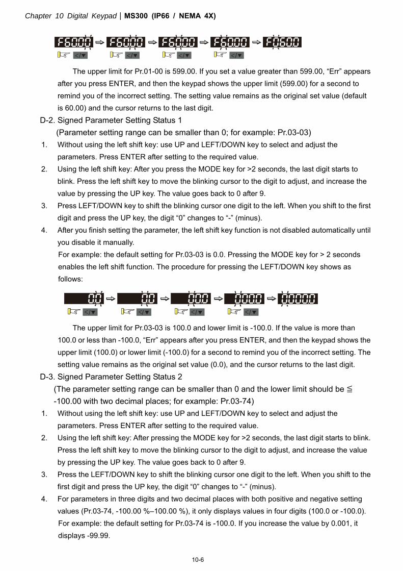
Chapter 10 Digital KeypadMS300 (IP66 / NEMA 4X)
10-6
< / < / < / < /
The upper limit for Pr.01-00 is 599.00. If you set a value greater than 599.00, “Err” appears after you press ENTER, and then the keypad shows the upper limit (599.00) for a second to remind you of the incorrect setting. The setting value remains as the original set value (default is 60.00) and the cursor returns to the last digit.
D-2. Signed Parameter Setting Status 1 (Parameter setting range can be smaller than 0; for example: Pr.03-03)
1. Without using the left shift key: use UP and LEFT/DOWN key to select and adjust the parameters. Press ENTER after setting to the required value.
2. Using the left shift key: After you press the MODE key for >2 seconds, the last digit starts to blink. Press the left shift key to move the blinking cursor to the digit to adjust, and increase the value by pressing the UP key. The value goes back to 0 after 9.
3. Press LEFT/DOWN key to shift the blinking cursor one digit to the left. When you shift to the first digit and press the UP key, the digit “0” changes to “-” (minus).
4. After you finish setting the parameter, the left shift key function is not disabled automatically until you disable it manually. For example: the default setting for Pr.03-03 is 0.0. Pressing the MODE key for > 2 seconds enables the left shift function. The procedure for pressing the LEFT/DOWN key shows as follows:
< / </ < / < /
The upper limit for Pr.03-03 is 100.0 and lower limit is -100.0. If the value is more than 100.0 or less than -100.0, “Err” appears after you press ENTER, and then the keypad shows the upper limit (100.0) or lower limit (-100.0) for a second to remind you of the incorrect setting. The setting value remains as the original set value (0.0), and the cursor returns to the last digit.
D-3. Signed Parameter Setting Status 2 (The parameter setting range can be smaller than 0 and the lower limit should be ≦ -100.00 with two decimal places; for example: Pr.03-74)
1. Without using the left shift key: use UP and LEFT/DOWN key to select and adjust the parameters. Press ENTER after setting to the required value.
2. Using the left shift key: After pressing the MODE key for >2 seconds, the last digit starts to blink. Press the left shift key to move the blinking cursor to the digit to adjust, and increase the value by pressing the UP key. The value goes back to 0 after 9.
3. Press the LEFT/DOWN key to shift the blinking cursor one digit to the left. When you shift to the first digit and press the UP key, the digit “0” changes to “-” (minus).
4. For parameters in three digits and two decimal places with both positive and negative setting values (Pr.03-74, -100.00 %–100.00 %), it only displays values in four digits (100.0 or -100.0). For example: the default setting for Pr.03-74 is -100.0. If you increase the value by 0.001, it displays -99.99.
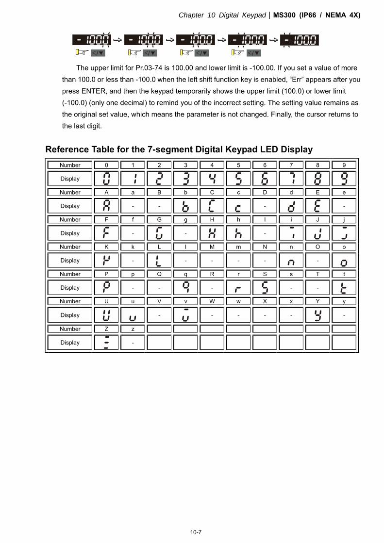
Chapter 10 Digital KeypadMS300 (IP66 / NEMA 4X)
10-7
< / </ < / < /
The upper limit for Pr.03-74 is 100.00 and lower limit is -100.00. If you set a value of more than 100.0 or less than -100.0 when the left shift function key is enabled, “Err” appears after you press ENTER, and then the keypad temporarily shows the upper limit (100.0) or lower limit (-100.0) (only one decimal) to remind you of the incorrect setting. The setting value remains as the original set value, which means the parameter is not changed. Finally, the cursor returns to the last digit.
Reference Table for the 7-segment Digital Keypad LED Display
Number 0 1 2 3 4 5 6 7 8 9
Display
Number A a B b C c D d E e
Display
- -
-
-
Number F f G g H h I i J j
Display
-
-
-
Number K k L l M m N n O o
Display - - - - - -
Number P p Q q R r S s T t
Display
- -
-
- -
Number U u V v W w X x Y y
Display -
- - - -
-
Number Z z
Display
-

Chapter 10 Digital KeypadMS300 (IP66 / NEMA 4X)
10-8
[This page intentionally left blank]
11 Summary of Parameter SettingsMS300 (IP66 / NEMA 4X)
11-1
11 Summary of Parameter Settings
All parameters and setting values in MS300 (standard models) series are applicable for those in
MS300 (IP66 / NEMA 4X) series except the following. Refer to Chapter 11 in MS300 (standard models) series for the rest of parameter settings.
1. Pr.00-20, setting value is 7 2. Pr.00-30, setting value is 7 3. Pr.03-39 4. Pr.03-40 5. Pr.03-41 6. Pr.03-42 7. Pr.03-43
Download the MS300 (standard models) series user manual at:
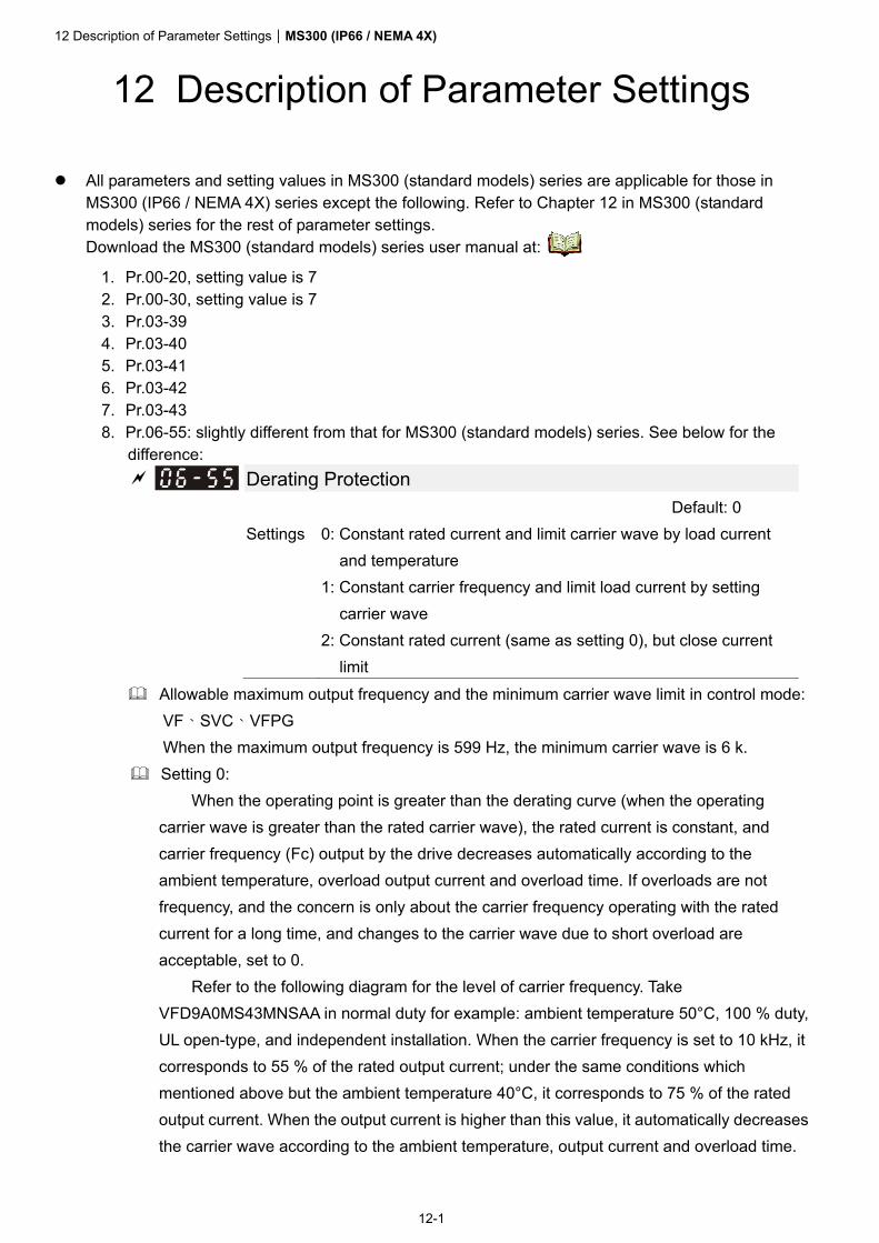
12 Description of Parameter SettingsMS300 (IP66 / NEMA 4X)
12-1
12 Description of Parameter Settings
All parameters and setting values in MS300 (standard models) series are applicable for those in MS300 (IP66 / NEMA 4X) series except the following. Refer to Chapter 12 in MS300 (standard models) series for the rest of parameter settings. Download the MS300 (standard models) series user manual at:
1. Pr.00-20, setting value is 7 2. Pr.00-30, setting value is 7 3. Pr.03-39 4. Pr.03-40 5. Pr.03-41 6. Pr.03-42 7. Pr.03-43 8. Pr.06-55: slightly different from that for MS300 (standard models) series. See below for the
difference: Derating Protection
Default: 0 Settings 0: Constant rated current and limit carrier wave by load current
and temperature 1: Constant carrier frequency and limit load current by setting
carrier wave 2: Constant rated current (same as setting 0), but close current
limit Allowable maximum output frequency and the minimum carrier wave limit in control mode:
VF、SVC、VFPG When the maximum output frequency is 599 Hz, the minimum carrier wave is 6 k.
Setting 0: When the operating point is greater than the derating curve (when the operating
carrier wave is greater than the rated carrier wave), the rated current is constant, and carrier frequency (Fc) output by the drive decreases automatically according to the ambient temperature, overload output current and overload time. If overloads are not frequency, and the concern is only about the carrier frequency operating with the rated current for a long time, and changes to the carrier wave due to short overload are acceptable, set to 0.
Refer to the following diagram for the level of carrier frequency. Take VFD9A0MS43MNSAA in normal duty for example: ambient temperature 50°C, 100 % duty, UL open-type, and independent installation. When the carrier frequency is set to 10 kHz, it corresponds to 55 % of the rated output current; under the same conditions which mentioned above but the ambient temperature 40°C, it corresponds to 75 % of the rated output current. When the output current is higher than this value, it automatically decreases the carrier wave according to the ambient temperature, output current and overload time.
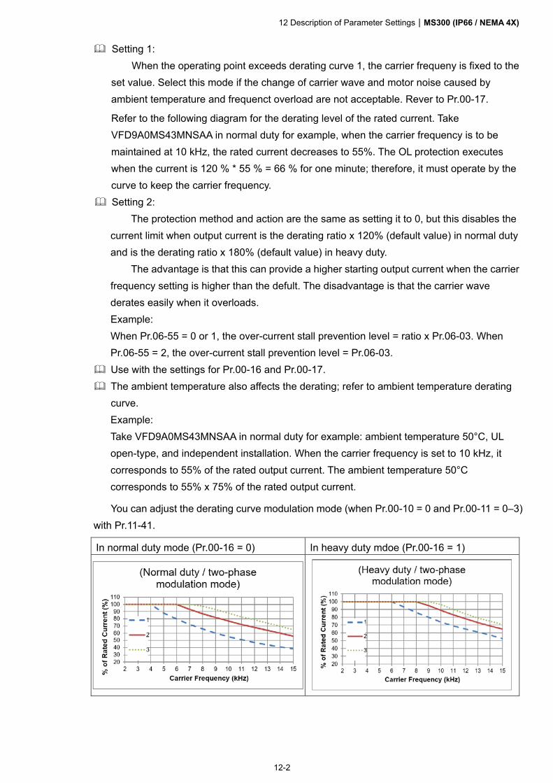
12 Description of Parameter SettingsMS300 (IP66 / NEMA 4X)
12-2
Setting 1: When the operating point exceeds derating curve 1, the carrier frequeny is fixed to the
set value. Select this mode if the change of carrier wave and motor noise caused by ambient temperature and frequenct overload are not acceptable. Rever to Pr.00-17.
Refer to the following diagram for the derating level of the rated current. Take VFD9A0MS43MNSAA in normal duty for example, when the carrier frequency is to be maintained at 10 kHz, the rated current decreases to 55%. The OL protection executes when the current is 120 % * 55 % = 66 % for one minute; therefore, it must operate by the curve to keep the carrier frequency.
Setting 2: The protection method and action are the same as setting it to 0, but this disables the
current limit when output current is the derating ratio x 120% (default value) in normal duty and is the derating ratio x 180% (default value) in heavy duty.
The advantage is that this can provide a higher starting output current when the carrier frequency setting is higher than the defult. The disadvantage is that the carrier wave derates easily when it overloads. Example: When Pr.06-55 = 0 or 1, the over-current stall prevention level = ratio x Pr.06-03. When Pr.06-55 = 2, the over-current stall prevention level = Pr.06-03.
Use with the settings for Pr.00-16 and Pr.00-17. The ambient temperature also affects the derating; refer to ambient temperature derating
curve. Example: Take VFD9A0MS43MNSAA in normal duty for example: ambient temperature 50°C, UL open-type, and independent installation. When the carrier frequency is set to 10 kHz, it corresponds to 55% of the rated output current. The ambient temperature 50°C corresponds to 55% x 75% of the rated output current.
You can adjust the derating curve modulation mode (when Pr.00-10 = 0 and Pr.00-11 = 0–3) with Pr.11-41.
In normal duty mode (Pr.00-16 = 0) In heavy duty mdoe (Pr.00-16 = 1)
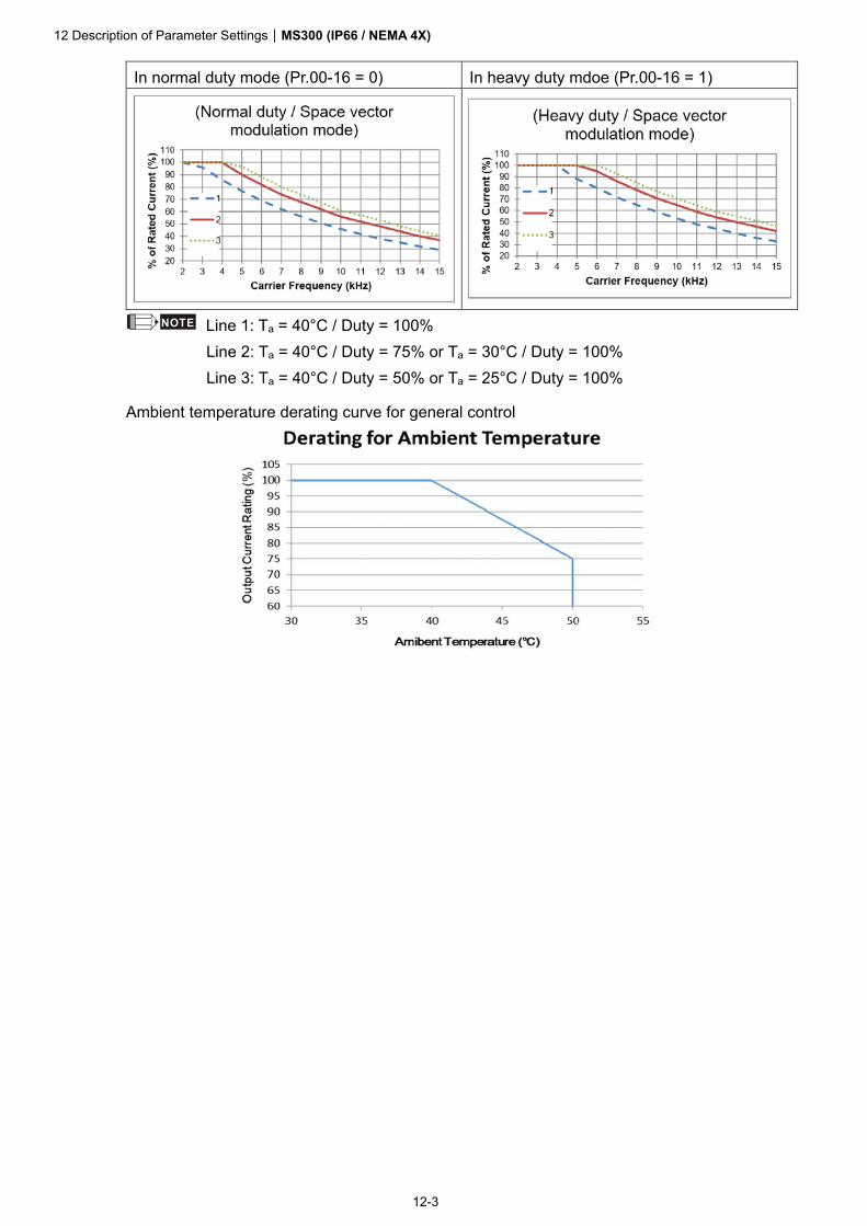
12 Description of Parameter SettingsMS300 (IP66 / NEMA 4X)
12-3
In normal duty mode (Pr.00-16 = 0) In heavy duty mdoe (Pr.00-16 = 1)
NOTE Line 1: Ta = 40°C / Duty = 100% Line 2: Ta = 40°C / Duty = 75% or Ta = 30°C / Duty = 100% Line 3: Ta = 40°C / Duty = 50% or Ta = 25°C / Duty = 100%
Ambient temperature derating curve for general control

13 Waring CodesMS300 (IP66 / NEMA 4X)
13-1
13 Warning Codes
Refer to Chapter 13 in MS300 (standard models) series for the information. Download the MS300 (standard models) series user manual at:

14 Error CodesMS300 (IP66 / NEMA 4X)
14-1
14 Error Codes
Refer to Chapter 14 in MS300 (standard models) series for the information. Download the MS300 (standard models) series user manual at:

15 CANopen OverviewMS300 (IP66 / NEMA 4X)
15-1
15 CANopen Overview
Refer to Chapter 15 in MS300 (standard models) series for the information. Download the MS300 (standard models) series user manual at:

16 PLC Function ApplicationsMS300 (IP66 / NEMA 4X)
16-1
16 PLC Function Applications
Refer to Chapter 16 in MS300 (standard models) series for the information. Download the MS300 (standard models) series user manual at:

17 Safe Torque Off FunctionMS300 (IP66 / NEMA 4X)
17-1
17 Safe Torque Off Function
Refer to Chapter 17 in MS300 (standard models) series for the information. Download the MS300 (standard models) series user manual at:
Copyright © 2022 FDOKUMEN