Degrees of Accessibility - XRCVC
190
Degrees of Accessibility A 360◦ User Perspective Report on existing accessible Geometry Construction Kits for students with blindness by Xavier’s Resource Centre for the Visually Challenged (XRCVC)
-
Upload
khangminh22 -
Category
Documents
-
view
3 -
download
0
Transcript of Degrees of Accessibility - XRCVC

Degrees of AccessibilityA 360◦ User Perspective Report on existing accessible
Geometry Construction Kits for students with blindness
by
Xavier’s Resource Centre for the Visually Challenged (XRCVC)

Degrees of Accessibility A 360° User Perspective Report on Existing Accessible Geometry Construction Kits
for students with blindness
Based on the research conducted by: Xavier's Resource Centre for the Visually Challenged (XRCVC)
As part of the Great Eastern CSR Foundation's Inclusive Education Project
Copyright © 2019 Produced and Published by The Xavier's Resource Centre for the Visually Challenged
(XRCVC) Mumbai, India ISBN Print Edition: 978-81-929012-6-8
ISBN E Book: 978-81-929012-7-5

“Blind students can do this when this topic comes in class!”
- Research Participant
“Oh this is what is a compass…I have seen it before in a pencil box, but never knew what it is used for or how it is used”
- Research Participant
Come join us on our journey of learning from our students!

Degrees of Accessibility |i
XRCVC
PREFACE Education, in its formalised avatar, has built an extensive system of curriculum delivery mechanism through the school system. Each subject is taught to the student in their respective classes, practised at home, and mastered through the course of the student’s participation in school. A successful completion of all subject curriculums, curated by educationists, aims to give the student a step forward in building careers post their schooling years. Have we wondered then, for students with disabilities, and here we are discussing for students with blindness and low vision in particular, by telling them that they ‘cannot’ study some of these well-curated curriculums and opt for alternative subjects, are we giving them the same career opportunities? Or are we flexible in our curriculums which we otherwise so vehemently insist on all school students to undergo? Given that the latter is not true, the XRCVC has been actively working to understand the reasons for the former so that the gaps can be bridged. Our work on making mathematics and science accessible for students with blindness and low vision started with our research report Numbers and Reactions (2013), which highlighted for us the reasons for lack of access to Science, Technology, Engineering, and Mathematics (STEM) subjects for students with blindness and low vision. Since then, our work has expanded to spreading awareness, conducting training programmes, and building up resources for accessible STEM study. The current research resulted from a strong need in the field of accessible STEM study. Geometry, as a subject inherent to high school mathematics, is often considered out of reach for students with blindness and low vision. It is assumed to be a purely visual subject. This, however, is far from the truth. What our eyes study in shapes is accessible to touch as well. Both 2D and 3D shapes are tactually accessible. However, this means that geometry study kits and construction tools, designed so far only for the eyes, have to be designed keeping in mind the sense of touch. The world over, several tactile accessible geometry construction tools have been developed and used over the years. When we interacted with students and teachers, what we found was that most tools were being adapted in their usage by teachers locally, in the absence of a clear-cut methodology shared by developers of the tools. Further, all tool sets could not do all tasks and a complete geometry construction kit including all parts was, oftentimes, missing. This made it nearly impossible for the student to perform all elements of geometry construction. This motivated the XRCVC team to carry out a systematic investigation of the subject. The aim was to collate most widely used national and international geometry construction sets, test them with a wide user base and be able to identify features to develop a comprehensive geometry construction kit that will make teaching and learning of geometry accessible and effective. The current report is a culmination of this ambitious idea that took seed two years ago. We have tried our best to put together a report that accounts for maximum number of learning variations. The report however does not claim to be a complete account of every tool that might exist. Further, the methods used to teach these tools have been adapted based on what was used locally and based on the XRCVC’s work experience. The same may not match the methods as envisaged by the tool designers. We would also like to affirm that the XRCVC has conducted this study for applied research purposes only and we do not hold any commercial interest in any of the tools studied. The XRCVC presents this work as a start point to documentation in this area, which it will look forward to building with collaborators in the future.

Degrees of Accessibility |ii
XRCVC
The XRCVC would like to extend heartfelt gratitude and thanks to the Great Eastern CSR Foundation for funding support extended under our Inclusive Education Project that made this research possible. Without this, the research would never have taken off. We also acknowledge and thank other organisations and individuals whose involvement has helped ensure the success of this research. We would like to acknowledge the key role played by the Tech Mahindra Foundation in partnership with whom XRCVC was able to launch its focus on accessible STEM education. We also thank the Dhun Pestonji Parakh Discretionary Trust whose ongoing support through the years has enabled us to investigate and work on diverse accessibility issues for persons with blindness and low vision. Special mention needs to be made of Smt. Kamla Mehta Dadar School for the Blind, Mumbai; Kanu Bhai Andh Vidyalay Malkapur, Akola; N.A.B. School for the Blind, Junagadh; Saksham Resource centre for visually impaired, multipally handicapped & deafblind children, New Delhi; The Victoria Memorial School for the Blind (VMSB), Mumbai, students of St. Xavier’s College, Mumbai, and students who came independently to us from other colleges in Mumbai. These institutes and individuals helped us to facilitate research at their respective locations and with their students. Without their support, the research vision would have remained on paper. We are tremendously grateful to each and every one of our students and their parents for taking time out from their already packed study schedules and their much illusive play time to be patient in learning all our tools and testing them for us. In helping us learn how they learn, the students’ invaluable time, efforts and inputs are what make this research report relevant and valuable. We hope that this report will prove to be useful reading to anyone interested in working with or designing universally accessible geometry construction kits for all students including students with blindness and low vision. And we look forward to someone being inspired by this and creating the next generation of accessible Geometry Construction Kits making all the time invested by our students in giving valuable inputs lead to something useful for the community at large.
Dr. Sam Taraporevala Research Director December 2019

Degrees of Accessibility |iii
XRCVC
PROJECT IMPLEMENTER
Xavier’s Resource Centre for the Visually Challenged (XRCVC), St. Xavier’s College, Mumbai (www.xrcvc.org) The XRCVC is a state-of-the-art support and advocacy centre for persons with disabilities in general and persons with blindness and low vision in particular. It is a department of St. Xavier’s College, Mumbai, India, and works actively in providing inclusive education services to students with disabilities on campus. It also does active work in providing Support and Training Services to persons with blindness and low vision, Awareness Generation and Advocacy Initiatives. The XRCVC works actively towards building access and inclusion both at the micro and the macro levels. One key area of work by the XRCVC has been Education Access for persons with disabilities. Our work has aimed at opening up more educational streams for persons with disabilities especially in the traditionally denied STEM fields as also building up resources of training, education content, and teaching learning aids for making STEM education possible. The current research is part of our endeavour to increase access to quality teaching-learning tools in the STEM discipline to persons with blindness and low vision. Project Team Dr. Sam Taraporevala Research Director Director, XRCVC; Associate Prof & Head, Department of Sociology and Anthropology, St Xavier’s College Ms. Neha Trivedi Research Coordinator Project Consultant, XRCVC Ms. Rebecca Carvalho Research Officer, Consultant, Maths and Science Access Project, XRCVC Ms. Aarohi Damle Research Author and Editor, Degrees of Accessibility Editorial Assistance Mr. Krishna Warrier Consultant, Awareness and New Projects, XRCVC Ms. Calveena D'Sylva Consulting Coordinator (Special Education)

Degrees of Accessibility |iv
XRCVC
READING GUIDE FOR THE RESEARCH REPORT
The research report has been divided into four main sections. We present below the framework for the same to facilitate an effective reading experience for readers of this report.
Section I: Chapters 1-2: Introduction and Research Framework This section will enable the reader to understand the context, need and framework used in the research. Since this research was a dual process of teaching respondents followed by testing them, it is critical for the reader to first understand the teaching pedagogy in the research. Further, this report uses a wide range of tools so unless the reader spends time understanding the tools and teaching pedagogy, subsequent reading may pose some challenges. Teaching pedagogy is part of Annexure G and we strongly recommend reading through the same.
Section II: Chapters 3-5: Skill-wise Analysis This section presents a skill-wise analysis of the research data. This section is useful for readers interested in obtaining an overall idea of features of tools that will be effective for specific skills. Each chapter provides design ideas for tools relevant for the skill analysed in the chapter.
Section III: Chapters 6-9: Tool-wise Analysis This section presents a tool wise analysis of the research data. It is especially useful for designers of specific tools studied in this research or for readers interested in understanding challenges associated with specific tools. Each chapter provides challenges associated with specific tools along with design suggestions for improving individual tool designs. The chapters also provide cross-tool analysis for accuracy and user feedback for a cross-tool comparison.
Section IV: Chapter 10: Conclusion and Way Forward The last section of the research provides for a distillation of learning from the research process to provide a design brief for future tool designs. It highlights challenges and sets forth potential work for the future. This section will be of interest to any reader who wishes to design accessible geometry construction kits. In addition to the above, the report has presented a list of annexures and tables as also abbreviations for easy reference and use for its readers. These can be accessed as part of the Table of Contents section of the report.

Degrees of Accessibility |v
XRCVC
LIST OF TABLES Table 2.1: Distribution of Nature of Respondents
Table 2.2: Distribution of Nature of Respondents by Gender
Table 2.3: The Skill Framework of the Research
Table 2.4: Tools Used in the Research Process
Table 2.5: Tool Combinations Across The Six Skills
Table 2.6: Overview of Training Elements of the Research
Table 3.1: Skill 1: Key Issues: Training Phase (%)
Table 3.2: Skill 1: Key Issues: Test Phase (%)
Table 3.3: Skill 2: Key Issues: Training Phase (%)
Table 3.4: Skill 2: Key Issues: Test Phase (%)
Table 4.1: Skill 3: Key Issues: Test Phase (%)
Table 4.2: Skill 4: Key Issues: Training Phase (%)
Table 4.3: Skill 4: Key Issues: Training Phase (%)
Table 4.4: Skill 4: Key Issues: Test Phase (%)
Table 5.1: Skill 5: Key Issues: Training Phase (%)
Table 5.2: Skill 5: Key Issues: Test Phase (%)
Table 5.3: Skill 6: Key Issues: Training Phase (%)
Table 5.4: Skill 6: Key Issues: Test Phase (%)
Table 6.1: Summary of Key Issues of APH Ruler across Relevant Skills
Table 6.2: Summary of Key Issues of Draftsman Ruler across Relevant Skills
Table 6.3: Summary of Key Issues of Garg Ruler across Relevant Skills
Table 6.4: Summary of Key Issues of RNIB Ruler across Relevant Skills
Table 6.5: Summary of Key Issues of Squirrel Ruler across Relevant Skills
Table 6.6: Summary of Key Issues of Squirrel; Ruler across Relevant Skills
Table 6.7.Test Stage Results for Skill 1: Drawing a Line Segment (%)

Degrees of Accessibility |vi
XRCVC
Table 6.8 Test Stage Results for Skill 2: Measuring a Line Segment (%)
Table 6.9 Test Stage Results for Skill 3: Constructing an Angle (%)
Table 6.10 Test Stage Results for Skill 5: Constructing a Circle (%)
Table 6.11: Questionnaire response of Users for Rulers across Skills (%)
Table 6.12: Rulers selected for Games Across Skills (%)
Table 6.13: Reasons for Easiest and Most liked Rulers across skills
Table 6.14: Reasons for Most Difficult and Least Liked Rulers across Skills
Table 7.1 Summary of Key Issues of APH Wand-inside Protractor across Relevant Skills
Table 7.2 Summary of Key Issues of APH Wand Protractor across Relevant Skills
Table 7.3 Summary of Key Issues of the Garg Protractor across Relevant Skills
Table 7.4 Summary of Key Issues of RNIB Protractor across Relevant Skills
Table 7.5 Summary of Key Issues of WT Protractor across Relevant Skills
Table 7.6 Test Stage Results for Skill 3: Constructing an Angle (%)
Table 7.7 Test Stage Results for Skill 4: Measuring an Angle (%)
Table 7.8: Questionnaire response of Users for Protractors Across Skills (%)
Table 7.9: Protractors selected for Games Across Skills (%)
Table 7.10: Reasons for Easiest and Most-liked protractor across skills
Table 7.11: Reasons for Most Difficult and Least Liked Protractor across Skills
Table 8.1: Summary of Key Issues of Classmate Compass across Relevant Skills
Table 8.2: Summary of Key Issues of APH Compass across Relevant Skills
Table 8.3: Summary of Key Issues of Garg Compass across Relevant Skills
Table 8.4: Summary of Key Issues of Worth Trust Ruler as Compass across Relevant Skills
Table 8.5 Test Stage Results for Skill 5: Constructing a Circle (%)
Table 8.6 Test Stage Results for Skill 6: Constructing/Cutting Arcs (%)
Table 8.7: Questionnaire response of Users for Compass across Skills (%)
Table 8.8: Compass selected for Games Across Skills (%)
Table 8.9: Reasons for Easiest and Most-liked Compass across skills

Degrees of Accessibility |vii
XRCVC
Table 8.10: Reasons for Most Difficult and Least Liked Compass across Skills
Table 9.1: Board Cross-Skill Questionnaire Objective Data (%)
Table 9.2 Board Cross-Skill Questionnaire Selected for Game (%)
Table 9.3: Reasons for Easiest and Most-liked Board across skills
Table 9.4: Reasons for Most Difficult and Least Liked Board across Skills
Table 9.5 Sheet Cross-Skill Questionnaire Objective Data (%)
Table 9.6.Sheet Cross-Skill Questionnaire Selected for Game (%)
Table 9.7: Reasons for Easiest and Most-liked TD Sheets across skills
Table 9.8: Reasons for Most Difficult and Least Liked Sheets across Skills

Degrees of Accessibility |viii
XRCVC
LIST OF ABBREVIATIONS STEM Science, Technology, Engineering, and Mathematics
TSBVI Texas School for the Blind and Visually Impaired
3D three-dimensional
TLA / TLAs Teaching-Learning Aids
GCK / GCKs Geometry Construction Kit(s)
NIEPVD National Institute for the Empowerment of Persons with Visual Disabilities
(Divyangjan)
NIVH National Institute for the Visually Handicapped
RNIB Royal National Institute of Blind People
APH The American Printing House for the Blind
WT WORTH Trust (Workshop for the Rehabilitation and Training of the Handicapped
Trust)
Cm Centimetre(s)
Mm Millimetre(s)
° Degree
TD / TDs Tactile Diagram(s)

Degrees of Accessibility |ix
XRCVC
TABLE OF CONTENTS PREFACE i
PROJECT IMPLEMENTER iii
READING GUIDE FOR THE RESEARCH REPORT iv
LIST OF TABLES v
LIST OF ABBREVIATIONS viii
CHAPTER 1. SETTING THE CONTEXT: AN INTRODUCTION 1
o The Challenge
o Research Framework
CHAPTER 2. THE RESEARCH PROCESS: THE TEACHING-LEARNING EXCHANGE 6
o Overall research design (Sample, Framework and Process)
o The GCKs and tools used and tested in the research
o Tool combinations across skills
o The specific pedagogy of teaching used in the research
CHAPTER 3. WORLD OF LINES 26
o Skill 1 Training and Test Results and Observer Inferences
o Skill 2 Training and Test Results and Observer Inferences
o Key Design Inferences for the Tools related to the skill of drawing and measuring line
segments
CHAPTER 4. WORLD OF ANGLES 38
o Skill 3 Training and Test results and Observer Inferences
o Skill 4 Training and Test results and Observer Inferences
o Key Design Inferences for the Tools related to the skill of constructing and measuring angles
CHAPTER 5. WORLD OF CIRCLES AND ARCS 54
o Skill 5 Training and Test results and Observer Inferences
o Skill 6 Training and Test results and Observer Inferences
o Key Design Inferences for the Tools related to the skill of constructing circles and arcs
CHAPTER 6. TOOL-SPECIFIC ANALYSIS: RULERS 66
o APH Clip Ruler
o Draftsman Ruler
o Garg Ruler
o RNIB Ruler
Degrees of Accessibility |x
XRCVC
o Squirrel Ruler
o WT Ruler
o Effectiveness of Tools Across Skills
o Questionnaire Responses: User Experience
CHAPTER 7. TOOL-SPECIFIC ANALYSIS: PROTRACTORS 90
o APH Wand-inside Protractor
o APH Wand Protractor
o Garg Protractor
o RNIB Protractor
o WT Protractor
o Effectiveness of Tools Across Skills
o Questionnaire Responses: User Experience
CHAPTER 8. TOOL-SPECIFIC ANALYSIS: COMPASS 106
o Classmate Compass
o APH Compass
o Garg Compass/ Markers
o WT Ruler as Compass
o Effectiveness of Tools Across Skills
o Questionnaire Responses: User Experience
CHAPTER 9. TOOL-SPECIFIC ANALYSIS: BASE TOOLS 118 (Drawing Boards, Sheets, Pins, Styluses)
o Key Issues for Drawing Boards, Sheets, Pins and Styluses
o Questionnaire Responses: User Experience: Boards
o Questionnaire Responses: User Experience: Sheets
CHAPTER 10. WAY FORWARD: DESIGN BRIEF AND CONCLUSION 127
o Design Brief for Comprehensive Geometry Kit
o Conclusion and Way Forward
LIST OF ANNEXXURES 138
ANNEXURE G 139
REFERENCES 174

Degrees of Accessibility |1
XRCVC
CHAPTER 1. SETTING THE CONTEXT: AN INTRODUCTION Mathematics, as a subject, holds a central and significant position within the formal education
system. In India, mathematics is compulsory in all primary and secondary schools. Often school
curriculums and merit are centred around sound mathematical knowledge. Given its importance, no
student can be considered exempt from partaking in the teaching and learning processes of
mathematics.
Traditionally, mathematics, and more specifically geometry, is considered beyond the understanding
of students with blindness and low vision — given its visual nature, representation and reproduction.
However, it is the classical methods of teaching geometry involving the use of visual modalities like
graphs, lines, drawings etc. (Rouzier et al., 2004) that make the subject exclusionary.
Douglas Clements writes extensively on geometric thinking as a means of not only learning
mathematical concepts but also developing spatial reasoning/awareness
(https://files.eric.ed.gov/fulltext/ED436232.pdf). Thus, teaching geometry to students with blindness
and low vision is as important for their understanding of mathematical concepts as for their
performing everyday tasks.
The development and ready availability of teaching recommendations like the Teacher’s Manual for
Adapting Science Experiments for Blind and Visually Impaired Students by Dion, Hoffman and Matter
(2000) or Teaching Math to Students Who are Blind or Visually Impaired by Osterhaus of the Texas
School for the Blind and Visually Impaired (TSBVI) are circumventing the visual limitation to teaching
and learning geometry and improving the mathematical content available to students with blindness
and low vision. In terms of assistive technologies available to persons with blindness and low vision
to learn mathematics, Karshmer and Bledsoe (2007) classify the available technologies as per
techniques used: tactile graphics; tonal representations; audio aids; haptic feedback and integrated
approaches.
Batista cites that Leon et al., (2016) writes that the best way persons with blindness and low vision
receive information about geometric and mathematical concepts is through touch and sound.
Therefore, the use of tactile graphics and more concrete materials, i.e. manipulatives, are
considered effective mediums for delivering mathematical instructions (Brawand and Johnson,
2016). The use of manipulatives or ‘objects designed to represent explicitly and concretely
mathematical ideas that are abstract’ (Moyer, 2001 p.176) is not a new technique employed for
teaching mathematics in schools. Manipulatives have both visual and tactual appeal thereby making
them accessible to all students.
The present day technologies that are being created to assist students with blindness in learning and
performing geometry are looking to utilize the ability to hear and touch. There is increasing research
and development of software that allows for the study and manipulation of geometric figures
virtually. 3D printing technology has opened up the scope for converting images into models in real
time. Software solutions like MathTrax have enabled graphs to receive audio feedback. However,
the problems with availability, cost, effectiveness and integration of these complex assistive
technologies into primary and secondary school curriculum have to be looked at critically.
There exists a dearth of information on available geometry tools that make geometry construction
possible for students with blindness in schools at simple and cost effective manner. This is not to say
that these tools do not exist, but their usability and effectiveness have not been adequately studied.

Degrees of Accessibility |2
XRCVC
Robison’s (2007) work found that the progressive step method of teaching geometric constructions
to students in Chennai was successful. However, the progressive step method involved the depiction
of consecutive stages of construction in tactile format. Students did not perform these practical
geometry constructions individually or independently. Tanti (N.D.) made use of a tactile ruler, a
protractor and a spur wheel to aide practical geometry constructions when teaching geometry in
Malta. Her work finds that the students could adequately perform geometric constructions albeit
with minor errors, when the students were able to memorise the method and gradually perform all
the steps in person.
In terms of availability of geometry tool kits, Pradhan and Samantha (2018) inventoried the assistive
technologies – including geometry kits – available in specialised institutes for the blind across two
divisions in West Bengal. Their research reiterates the need for increased access, availability and
funding for assistive technologies and trained professionals.
The Challenge
As an organisation that has been actively working on building access to STEM education for persons
with blindness and low vision, the XRCVC has been encountering the concerns listed above at
multiple levels. Our work in accessible STEM for students with blindness and low vision started with
our first research in the field published in the report Numbers and Reactions (2013). The report had
highlighted the following key areas of intervention needed to make STEM study more accessible and
available in India.
Availability of Teaching-Learning Aids (TLAs)
Content Creation and TLA manufacturing locally to reduce costs
Learning services to students and training of trainer services to educators
Awareness
Our work post the research lead us to start collating and collecting resources and TLAs available in
the field both nationally and internationally to start building up a local library. Simultaneously, we
also started building our in-house capacities for training students in STEM-related special skills such
as Nemeth, LaTeX, ASCIIMath, Geometry Skills, Lab Skills, etc., and started offering these to students
directly as also to trainers for subsequent dissemination.
It was during our implementation of Geometry Skills to students with blindness and low vision that
we encountered some challenges. These could be highlighted as follows:
Variety of tools being used: Our work with different students led us to a variety of geometry
construction kits that were being used by different organisations, parents and special
educators.
Diversity in operation of similar tools: Even when students and special educators were
using similar tools, the methods for using them varied. Many times, either the tools did not
come with “how to use” manuals, or even if they did, the methods were adapted by tutors
and students.
Lack of usage: Even though a large number of students owned the locally available tools,
they had never used them because they did not know how to.
Lack of a Comprehensive Geometry Construction Kit causing difficulty in constructions and
eventual loss of interest: We also found that students were using stand-alone tools to do

Degrees of Accessibility |3
XRCVC
scattered geometry work rather than a comprehensive kit, akin to their sighted peers.
For e.g., most students with blindness identified only the protractor and ruler in the kit and
not a compass. This also meant that the number of geometry constructions were restricted.
Moreover, to use many of these instruments, additional side tools – in terms of pins, sheets
or drawing boards – were not standardised or readily available. Students would depend on
locally available products for the same, and oftentimes, find it challenging to draw with
those products not meeting the design requirements for effective drawing. Once ineffective
tools made constructions difficult, it would lead to a rapid loss of interest for learning among
tutors and students alike.
Few solutions for same-side drawing: Most tools available used reverse-style drawing as a
method because earlier the same-side drawing method was not in use. In geometry
construction, reverse-side drawing always added complexity and difficulty leading to
frustration and loss of interest.
When we encountered these issues, we thought it apt to undertake a comprehensive research on
existing Geometry Construction Kits (GCK) to ascertain the real design challenges as also possible
solutions. It was also clear to us that the research would need to keep user experience and feedback
as the key to investigation. Given that many students did not study geometry to be able to give
comprehensive feedback across all tools available in the market, the study had to be envisaged as
both a teaching and feedback design.
This report is a compilation of the research undertaken and aims to make data available on the
existing GCKs in schools for students with blindness and low vision. The research highlights the
usability of these kits and their effectiveness. The report also aims to bring to light the possible
design solutions for a comprehensive GCK suitable to the Indian market to make access to geometry
easier and fun for students with blindness and low vision.
Subsequent sections of this chapter highlight the research details.
Research Framework
The Key Research Objective was the following: To research and identify the most effective design elements for building a comprehensive accessible Geometry Construction Kit (GCK) for students with blindness and low vision The Key Activities identified for the research included the following:
To undertake research and identify the list of existing GCKs available for students with
blindness and low vision
To be able to identify and document the pedagogy of using each of the GCKs available in the
market
To teach users how to use the existing GCKs and subsequently test for effectiveness of the
kits in constructions, as also obtain user feedback on their usefulness
Expected Outcomes of the research included the following:
A holistic understanding of the effectiveness and challenges of existing GCKs

Degrees of Accessibility |4
XRCVC
A clear understanding of useful and effective design elements of GCKs that can make
geometry construction accessible and efficient for students with blindness and low vision
To be able to develop a clear design brief for development of a comprehensive accessible
GCK.

Degrees of Accessibility |5
XRCVC
Scope:
The research aimed to focus on getting a more detailed understanding of use and effectiveness of
the GCKs in the Indian scenario. Secondary research and the list of GCKs used for the study were not
limited to India but those used across the globe were utilised. User-level testing and data collection
was limited to Indian respondents.
Research Method:
The Research used both primary and secondary data. Details of methodologies used for both are
listed below.
Primary Data Collection: For this, in-person training of students in the use of GCKs, testing and
simulated game environment was created. Data was collected through researcher observations at
this stage. In addition, the questionnaire method was used to collect specific feedback data from the
students.
Data was collected from a purposive random sample of totally blind boys and girls across urban and
semi-urban areas. Data was collected in Mumbai, Delhi, Junagadh and Akola. Further, to keep the
group diverse in age, students from Class 4 to 12 were made part of the study. For sample
classification, Classes 4-8 were considered as young, and Classes 9-12 as older.
The sample size was 40.
Sample Distribution
Female Male
Older Younger Older Younger
10 10 10 10
Percentages have been used to analyse the primary data collected.
The Researchers’ Observation sheets and questionnaires used for primary data collection are
attached as Annexure C, Annexure D and Annexure F.
The sample does not claim to have statistical confidence; the primary data collection has been an
exploratory process to gauge and identify ground level reality in the effectiveness of GCKs in the
study of geometry for students with blindness and low vision in India.
Secondary Data Collection: For this, the following was undertaken:
Literature review of national and international best practices in teaching and learning of
geometry among blind and low vision persons
An extensive compilation and procurement of as many as possible and popularly used GCKs
for students with blindness and low vision—both nationally and internationally
Subsequent chapters will highlight the detailed research design for primary data collection for
setting the overall framework of the report.

Degrees of Accessibility |6
XRCVC
CHAPTER 2. THE RESEARCH PROCESS: THE TEACHING-LEARNING EXCHANGE As listed in Chapter 1, the purpose of this research study has been to develop a clear understanding on the design of an effective GCK for students with blindness and low vision. As the research team started considering the design of such a study, it soon came to our realisation that in order to get user feedback on all the different GCKs we had to first have students who used all these available kits. Due to the existing bias at the ground level, it was nearly impossible to find enough number of students who were using all the GCKs that the research was interested in studying. Hence, it was acknowledged that the research would have to follow a different design. It would have to have a teaching phase followed by a feedback phase. This chapter aims to familiarise the reader of this report with the following:
I. Overall research design (Sample, Framework and Process)
II. The GCKs and tools used and tested in the research
III. Tool combinations across skills
IV. The specific pedagogy of teaching used in the research
I. Research Design
Given that the purpose of the research was to identify the most effective design elements for a comprehensive GCK, efforts were made to design the research process and the sample to ensure that one could elicit the maximum amount of feedback from as diverse a group as possible without any prior learning or exposure interfering with feedback. Presented below are details of the sample and the research process used. The Research Sample: The purposive sampling aimed to get inputs of respondents across gender, age and location. Efforts were made to ensure that a diverse sample would reflect design preferences that are as universally applicable as possible to create the design brief that will have high effectiveness for maximum number of users. The research was conducted in four locations, the two cities of Mumbai and Noida and the two semi-urban cities of Junagadh and Akola to ensure an urban-semi-urban variation. The sample size for the research was 40 participants with an equal number of female and male participants. The participants were grouped according to age, the younger group comprised of students from Class 4 to Class 8 and the older group comprised of students from Class 9 to Class 12. Also, for the purpose of this study, only the method for students with total blindness was used. While we initially wanted the full sample to be comprised of students with total blindness, in some rare cases where we did not find enough totally blind participants, some students with low vision were taken on with only their sense of touch used to work with the tools. The demographic distribution of the sample across age, gender and geographical location is documented in Tables 2.1 and 2.2 below.
Table 2.1: Distribution of Nature of Respondents
Location Older Younger
Total Male Female Male Female
City 3 8 6 4 21
Non-City 7 2 4 6 19
Total 10 10 10 10 40

Degrees of Accessibility |7
XRCVC
Table 2.2: Distribution of Nature of Respondents by Gender
Location Male Female Total
City 9 12 21
Non-city 11 8 19
Total 20 20 40
As reflected above, while the sample has tried to maintain diversity across age, gender and location, we were not able to get an equally representative sample for each category. Since the research process demanded a long time commitment it was difficult to find the exact number of respondents for each category. Further, the research also faced the challenge of respondents dropping out half way due to medical and logistical reasons, needing the research team to make modifications. However, this has been taken into consideration subsequently where location was not made into a variable of comparison but left only to a variating factor at the time of analysis. The Research Framework:
For the purpose of being able to receive specific feedback about existing GCKs, it was essential for the research to develop a sound framework against which data could be collected. This framework was developed in conjunction with the nuances of pedagogy of geometry as a field of study. Since the purpose of the study was to identify design elements related to GCKs, it was important to keep in mind the specific purpose of each tool and understand whether the design elements of the tool fostered or hindered the performance of the said task by the specific tool. In order to streamline and structure the same, the research has used a Skill Framework for the data collection and analysis. Geometry studying can be broadly divided into six core skills. These skills are used for geometry constructions across years of studying. The research has, therefore, used these skills as the bedrock to devise the research design and, subsequently, the data collection and analysis. The table 2.3 below presents the details of the skill framework.
Table 2.3: The Skill Framework of the Research
Sr. No.
Skill Name Tools in the GCK that will be used
1 Constructing a Line Segment Drawing Boards, Sheets to draw on, Pins, Styluses, Rulers
2 Measuring a Line Segment Drawing Boards, Tactile Diagrams, Pins, Rulers
3 Constructing an Angle Drawing Boards, Sheets to draw on, Pins, Styluses, Rulers, Protractors
4 Measuring an Angle Drawing Boards, Tactile Diagrams, Pins, Styluses, Rulers, Protractors
5 Drawing/Constructing a Circle Drawing Boards, Sheets to draw on, Pins, Styluses, Rulers, Compasses
6 Constructing /Cutting Arcs Drawing Boards, Sheets to draw on, Pins, Styluses, Protractors, Compasses
The research used a large number of tools, all of which are listed in the subsequent tools sections. Each of these tools was tested for their effectiveness for the skills that they apply to. The pedagogy used in teaching students each of the six skills listed above with all the tools being tested is explained in the subsequent section on pedagogy. But it is important to state that the research followed the teaching-testing and analysis of data within this skill framework.

Degrees of Accessibility |8
XRCVC
The Research Process:
The ground level reality was that not too many students with blindness had had exposure to geometry kits, and those who had, had primarily used the reverse-side drawing method of learning. Therefore, the research was designed such, that all respondents were first taught the abovementioned skills through usage of the tools selected for testing. Subsequently, they were tested and also observed under a neutralised game environment. In the end, user feedback was also procured through a questionnaire. The Process can be detailed out as below: Stage 1: Participant Registrations: Participants were made to sign a Consent Form and their details were recorded. While signing the consent form (or getting the form signed by their supervisors for minors), the students were informed about the entire study procedure listed here as well as the terms and conditions for participating in the research. The Consent Forms can be found in Annexure A and Annexure B. Stage 2: Training: The participants were trained in each of the abovementioned skills using the geometry tools selected in the research. Students were asked to continue to practise till they learnt the skill thoroughly. Observations were made and noted during this time. A video recording of the same was also taken. The researcher’s observation formats can be found in Annexure C. Stage 3: Test: At this stage, the participants were asked to perform one construction for each of the skills independently — for each tool combination presented by the researcher. Observations were made and noted during this time. A video recording of the same was also taken. The researcher’s observation formats can be found in Annexure D. Stage 4: Game Simulation: At this stage, the participants were given all the tool combinations taught and they were asked to select any one that they preferred to work with and perform one construction per skill based on the selected tool combination. Their tool selection was noted down for each skill. The researcher’s observation formats can be found in Annexure E. Stage 5: Feedback Questionnaire: The participants were made to answer a detailed questionnaire related to the tools used for each skill at the end of training, test and game simulation for each skill. On completion of all six skills, the participants were made to answer a detailed questionnaire about all the geometry tools used for the research across all skills. The questionnaire formats can be found in Annexure F. Some additional factors of the research process included the following:
The research process was undertaken as far as possible in groups of 4-5.
During the training and test sessions, each student would be trained and tested with
different tools. The students would take turns using the geometric tools and pass the tool on
to the next student till all the students in a batch had their turn. This was, both, a result of
time constraints and the number of each tool available at the disposal of the researcher.
The training, test, game and skill-specific questionnaire were completed for each skill at a
time, and only then would the researcher move to the next skill (in the majority of cases).

Degrees of Accessibility |9
XRCVC
II. Tools Used In the Research
For blind and low vision students, the challenges of teaching and learning a visually, spatially and practically-rich subject like geometry can be reduced with the availability of accessible reading and writing tools and tactually represented diagrammatic content. For practical geometric constructions, the availability and use of geometry tools is required. There are a wide range of GCKs and tools available in the world for students with blindness and low vision. This research narrowed down on the tools being tested based on a set of criteria. It is important to first understand the rationale for selecting the tools used for testing in this research before familiarising ourselves with each. Rationale for Selection of Tools
For the purpose of this study, only tools that permitted same side drawing were selected.
This is because the XRCVC team, through its own experience, is of the strong view that
reverse-side drawing tools make the construction process complex and is one of the biggest
reasons for students giving up on geometry. Hence, efforts need to be made towards
building an effective same side GCK.
The study has restricted itself to the use of only easy-to-carry tools and GCKs. There are
some same-side construction kits in the market that are quite bulky and would make their
day-to-day usage at school and home nearly impossible. It is for these reasons that certain
kits have been left out the study, such as the aluminium version available through the
National Institute for the Empowerment of Persons with Visual Disabilities (Divyangjan),
previously the National Institute for the Visually Handicapped (NIVH), Dehradun. The
purpose is to devise a kit that can be easily carried to the school everyday by the student.
Since the study was restricted to GCKs for students with total blindness alone, kits for those
with low vision have been kept out of the purview of this research.
It is also important to note, that this research has selected the tool for study based on the
XRCVC’s training experiences with students. There are other tools available not studied here.
The rationale for our selection was based on diversity of methods of tools as also those
found most effective in our trainings.
Based on the above rationale, the study has narrowed down on the following tools to be tested. Actual Tools Used in the Research
As listed in the skill framework, each skill required some primary tools and some base materials and tools that have been used across skills. The following table lists out the key categories and the specific tools under each category used for the study. The particular tools used are further illustrated and elaborated below.

Degrees of Accessibility |10
XRCVC
Table 2.4: Tools Used in the Research Process
Tool Category Specific Tool Names used in the Research
Rulers RNIB ruler, APH Clip ruler, WT ruler, Draftsman ruler, Squirrel ruler, Garg ruler
Protractors RNIB protractor, WT protractor, APH wand inside protractor, APH wand protractor, Garg protractor
Compasses Classmate compass, APH compass, Garg circle markers, Garg arc markers, WT ruler as compass
Drawing Boards Draftsman board, exam board with Silicon Mat, Garg board
Pins Regular Board pins, RNIB pins, RNIB knob, Garg point markers
Styluses Garg stylus, Line markers, typical stylus
Drawing Sheets Plastic sheet, Braille paper
Tactile Diagrams Thermoform sheet, Plastic sheet, Braille paper
A detailed description of the specific tools is provided below. It is essential for readers to familiarise themselves with the same before reading further to understand the research findings. Rulers
1. Royal National Institute of Blind People Tactile Ruler (hereafter RNIB Ruler) is a yellow and
black, 30 cm (centimetre) ruler with two distinct sides/edges: smooth and grooved. The smooth
side of the ruler has long and short tactile lines for every 10 mm (millimetres) and 5 mm mark
respectively. The grooved side of the ruler is equipped with a tactile line and a groove for every
10 mm measurement, but for a 5 mm measurement, only a corresponding groove is provided. At
every 5 cm measurement an extra-long tactile mark, extending across the width of the ruler
from the smooth side to the grooved side, is provided. This ruler has sighted print labels at
measurements of 1 cm to 10 cm and then at 15 cm, 20 cm, and 25 cm. It has no braille labels.
Figure 2.1: RNIB Ruler
2. American Printing House Tactile Ruler (hereafter APH Clip Ruler) is a 12 inch black plastic ruler
with a removable calliper. The ruler is marked in cm (centimetres) along one side, and in inches
on the other side. Long and short tactile lines denote every 10 mm and 5 mm mark respectively.
Braille labels are provided for every multiple of 2 on the centimetre side and for every inch on
the other side. The braille numeric indicator is skipped in the braille labels. It does not have any
sighted print labels.
Figure 2.2: APH Clip Ruler
Degrees of Accessibility |11
XRCVC
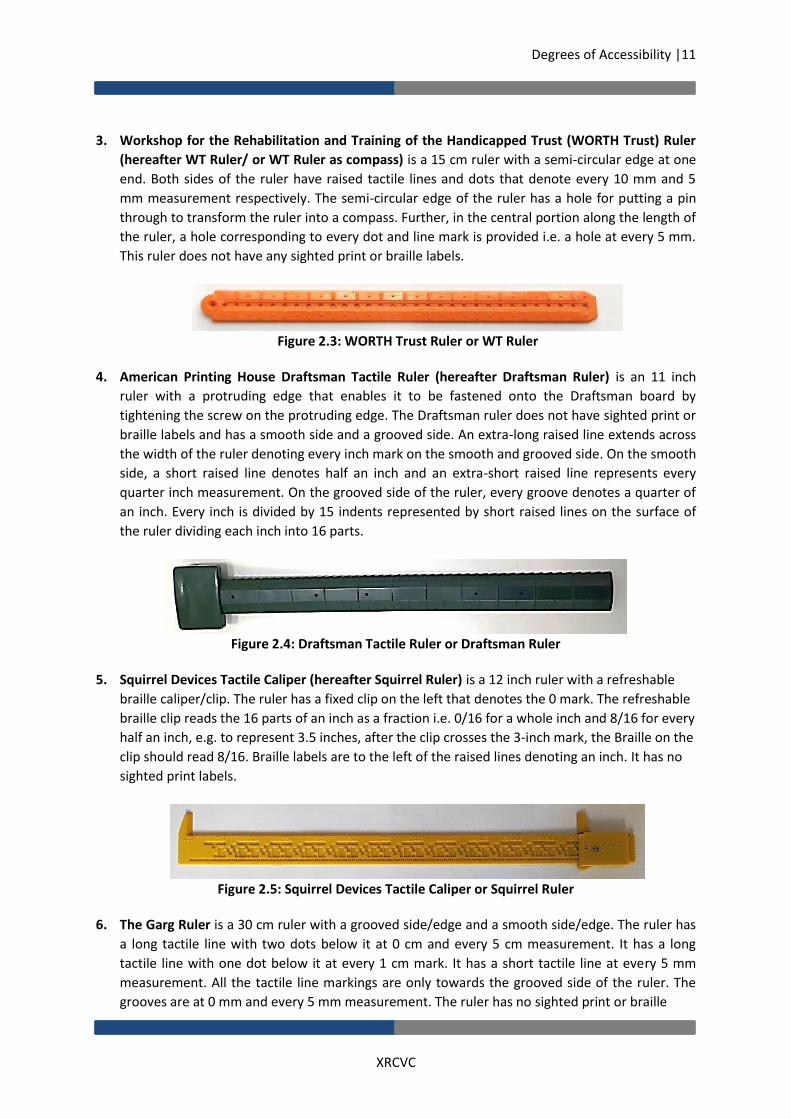
3. Workshop for the Rehabilitation and Training of the Handicapped Trust (WORTH Trust) Ruler
(hereafter WT Ruler/ or WT Ruler as compass) is a 15 cm ruler with a semi-circular edge at one
end. Both sides of the ruler have raised tactile lines and dots that denote every 10 mm and 5
mm measurement respectively. The semi-circular edge of the ruler has a hole for putting a pin
through to transform the ruler into a compass. Further, in the central portion along the length of
the ruler, a hole corresponding to every dot and line mark is provided i.e. a hole at every 5 mm.
This ruler does not have any sighted print or braille labels.
Figure 2.3: WORTH Trust Ruler or WT Ruler
4. American Printing House Draftsman Tactile Ruler (hereafter Draftsman Ruler) is an 11 inch
ruler with a protruding edge that enables it to be fastened onto the Draftsman board by
tightening the screw on the protruding edge. The Draftsman ruler does not have sighted print or
braille labels and has a smooth side and a grooved side. An extra-long raised line extends across
the width of the ruler denoting every inch mark on the smooth and grooved side. On the smooth
side, a short raised line denotes half an inch and an extra-short raised line represents every
quarter inch measurement. On the grooved side of the ruler, every groove denotes a quarter of
an inch. Every inch is divided by 15 indents represented by short raised lines on the surface of
the ruler dividing each inch into 16 parts.
Figure 2.4: Draftsman Tactile Ruler or Draftsman Ruler
5. Squirrel Devices Tactile Caliper (hereafter Squirrel Ruler) is a 12 inch ruler with a refreshable
braille caliper/clip. The ruler has a fixed clip on the left that denotes the 0 mark. The refreshable
braille clip reads the 16 parts of an inch as a fraction i.e. 0/16 for a whole inch and 8/16 for every
half an inch, e.g. to represent 3.5 inches, after the clip crosses the 3-inch mark, the Braille on the
clip should read 8/16. Braille labels are to the left of the raised lines denoting an inch. It has no
sighted print labels.
Figure 2.5: Squirrel Devices Tactile Caliper or Squirrel Ruler
6. The Garg Ruler is a 30 cm ruler with a grooved side/edge and a smooth side/edge. The ruler has
a long tactile line with two dots below it at 0 cm and every 5 cm measurement. It has a long
tactile line with one dot below it at every 1 cm mark. It has a short tactile line at every 5 mm
measurement. All the tactile line markings are only towards the grooved side of the ruler. The
grooves are at 0 mm and every 5 mm measurement. The ruler has no sighted print or braille

Degrees of Accessibility |12
XRCVC
labels. The ruler has three tiny magnets on its reverse side to enable it to somewhat stick to the
Garg board.
Figure 2.6: Garg Ruler
Protractors
1. Royal National Institute of Blind People Tactile protractor (hereafter RNIB Protractor) is
yellow with black visual markings with a semi-circular notch at the centre of the baseline of
the protractor. For every 5-degree measurement, the protractor has a short tactile line and a
corresponding groove. There are long tactile lines and every second groove representing a
10-degree measurement. An extra-long dashed line extending along the surface of the
protractor towards the notch at the centre of the base is marked at 45 degrees and 135
degrees each. Another extra-long but solid line extending along the surface of the protractor
towards the notch at the centre of the base is found at the 90-degree mark. The protractor
has no sighted print and braille labels.
Figure 2.7 RNIB Protractor
2. Workshop for the Rehabilitation and Training of the Handicapped Trust Protractor
(hereafter WT Protractor) is a small orange protractor with five tips at its base for better
alignment to the baseline. There are two immobilisation holes provided on the body of the
protractor near the baseline. The protractor has a long raised line and a corresponding
groove denoting every 10-degree mark; a raised dot is provided for every 5-degree
measurement. An extra-long raised line and a dot below it are provided at 30-, 60-, 90-, 120-
and 150-degree measurements.
Figure 2.8: WT Protractor

Degrees of Accessibility |13
XRCVC
3. American Printing House Tactile Protractor (hereafter APH Wand-inside Protractor) is a
transparent protractor with a ruler at its bottom edge (baseline) of the protractor. It is
equipped with a yellow moveable wand, connected at the centre just above the baseline
that extends a little over the surface of the protractor, thus crossing or covering the tactile
measuring marks under it. Two raised dots denote every 10-degree measurement and a
single dot denotes every 5-degree measurement. Three dots are provided to mark 0, 45, 90,
135, and 180 degrees each. Notches are provided at the bottom left and right side for
immobilisation. Braille labels are provided at 0, 45, 90, 135 and 180 degrees. It has no
sighted print labels.
Figure 2.9: APH Wand-inside Protractor
4. American Printing House Braille-Large Print Protractor: (hereafter APH Wand Protractor) is
a transparent protractor equipped with a large, blue moveable wand that extends much
beyond the surface of the protractor. One end of the wand is pointed and ends just below
the tactile measuring dots along the semi-circular scale of the protractor. The knob attaching
the wand to the baseline of the protractor can be tightened to fix/immobilise the moveable
wand in place. The protractor has sighted print measurement markings and two raised dots
to denote every 10-degree measurement and a single dot for 5-degree measurement. For
ease of measurement, three dots are provided at 0, 45, 90, 135 and 180 degrees. It has no
braille labels.

Degrees of Accessibility |14
XRCVC
Figure 2.10: APH Wand Protractor
5. Garg Protractor is designed like a wheel and has spokes and a central hole for
immobilisation. A long arm extends from the protractor that represents the 0-degree mark
and the baseline. The protractor has a long raised line for every 10-degree measurement
and a raised dot for every 5-degree measurement. A combination of a raised line and dot is
seen at the 30-, 60-, 90-, 120-, 150-, 180-, 210-, 240-, 270-, 300-, 330-, 360-degree
measurements. The spokes extend only at these measurements. At one of these
measurements, where the spokes extend, i.e. at every 30-degree interval), an extended line
marker is attached, thus making that the 0-degree and 360-degree mark on the protractor. It
has no sighted print or braille labels. It has tiny magnetic bits on its reverse side to enable it
to somewhat stick to the Garg board.
Figure 2.11: Garg Protractor
Compasses
1. The Classmate Compass has two legs; a sharp pin leg and a second leg with a slot for fixing a pen
/ pencil for drawing. The ballpoint pen can be fixed by loosening and tightening the screw. At the
top of the compass, a screw type knob is provided to immobilise the two legs in place.

Degrees of Accessibility |15
XRCVC
Figure 2.12: Classmate Compass
2. American Printing House compass (hereafter APH compass) has two legs; a fixed sharp pin leg
and a second leg with a spur wheel. This second leg is movable along a rod which has a ruler.
This inbuilt ruler provided on the compass has long and short tactile markings in centimetres on
one face/side and in inches on the other. The spur wheel leg slides over the ruler and can be
fixed at the desired measurement by tightening the screw placed on top of the spur wheel leg.
Figure 2.13: APH Compass
3. Garg Circle Markers (hereafter Circle Markers) are provided in set radius measurements as part
of the Garg kit. The circle markers have a wheel design with spikes and a central immobilisation
hole. A braille label is provided near the central immobilisation hole to identify the desired
radius measurement for drawing a circle.

Degrees of Accessibility |16
XRCVC
Figure 2.14: Garg Circle Markers
4. Garg arc markers (hereafter Arc Markers) have a wheel design with a central immobilisation
hole. A single wheel has three set radius measurements for drawing arcs. Braille labels are
provided near the central immobilisation hole for identifying the required arc for drawing.

Degrees of Accessibility |17
XRCVC
Figure 2.15: Garg Arc Markers
Boards
1. American Printing House Draftsman Drawing Board (hereafter Draftsman board) is a
rectangular board with a fixed silicon mat and foam screen. The short vertical sides of the board
have clasps that open to secure the sheets. The clasps and the top length of the board have
ridges that allow for the fastening of the Draftsman ruler. The bottom-right corner of the board
has the name of the board in sighted print and braille and the bottom-centre to left has a slot for
placing the stylus that comes with the board.
Figure 2.16: Draftsman Board
2. Exam Board with a Silicon mat is a rectangular board with a smooth surface which is used
vertically. A clip is provided along the upper breadth of the board to secure the sheets and the
mat on the board.
Silicon Mat has a smooth rubbery surface on one side and a foam screen on the other. The sheet being used is to be placed over the smooth side for constructions.

Degrees of Accessibility |18
XRCVC
Figure 2.17: Exam Board Figure 2.18: Silicon Mat
3. Garg Drawing Board (hereafter Garg board) is a rectangular board with a smooth surface which
is used vertically. A clip is provided along the upper breadth of the board to secure the sheets
and mat on the board. The surface of the board has a metal sheet underneath it to enable the
magnet stickers on the tools that are to be used with this board to stick. The clip when opened
has two tiny magnet bits to allow it to close securely over the paper. The clip also has two holes
on one side and two projections on the other side to create a mark on the paper once set in the
board, so that with those marks the paper can easily be reset later, similar to the concept of the
braille slate. Along the two vertical edges of the board, tactile indents are provided equally
aligned to aid in straight alignment of the ruler on the board, similar to the concept of the
wooden braille slate with the removable metal strip.
Figure 2.19: Garg Drawing Board or Garg board
Pins
1. Push pins or regular board pins (hereafter regular pins) were used throughout the research by
the participants to immobilize some of the tools and the sheet.

Degrees of Accessibility |19
XRCVC
Figure 2.20: Push Pin or Regular Board Pin
2. Royal National Institute of Blind People protractor pins (hereafter RNIB pins) are yellow RNIB
pins that are a part of the RNIB protractor apparatus and are used to mark the vertex point of
the angle. It is also used to mark the end points of a segment and/or measurement marks. The
metal pin portion of the RNIB pins is longer than that of regular pins and the yellow plastic top of
the pin is cylindrical.
Royal National Institute of Blind People protractor knob (hereafter RNIB Knob) is a yellow cone shaped knob and is part of the RNIB protractor apparatus. The broader base of the cone is placed over the vertex RNIB pin to mark the vertex. The RNIB protractor rests on the RNIB knob at the baseline.
Figure 2.21: RNIB Knob and RNIB Pin
3. Garg Kit Point Markers (hereafter Point Markers) are small circular pin with magnets at the
base. The magnet pin is attached to a butterfly shaped handle that assists in positioning/moving
the pin on the board
Figure 2.22: Garg Point Marker
Styluses
1. Garg Stylus is a thin cuboid about 4 inches. The Garg stylus has a small bulge on one end that
acts as a hook that is used to draw over the line markers.

Degrees of Accessibility |20
XRCVC
Figure 2.23: Garg Stylus
2. Garg Line Marker (hereafter Line Markers) are two thin plastic bars of different lengths based
on their use. The line markers have a dome-shaped bulge on one side and a flat surface on the
other. The flat part of the line marker has an indent that runs along the entire length.
The Line Marker Bridge that comes with the line maker is a square with tactile lines for supporting the line marker. It has a magnetic base.
Figure 2.24: Garg Line Markers
Figure 2.25: Line marker bridge
3. Typical stylus is the regular round head or wing stylus that has a pointed nib used for braille
writing on braille slates.
Figure 2.26: Two Typical styluses
Sheets
1. Plastic Sheets are thin translucent sheets or films known commonly as parchment paper/ swell
paper/ drawing sheets/ drawing film in different countries. The same are also provided along
with the APH Draftsman Board Drawing kit. When placed on a silicon/rubber mat and drawn on
with sufficient pressure, they tend to raise on the same side.

Degrees of Accessibility |21
XRCVC
Figure 2.27: Plastic Sheet
2. Braille Paper is regular braille paper of 120-140 GSM used for braille writing on slates/braillers.
Figure 2.28: Braille Paper
Tactile Diagrams (TDs)
1. Thermoform Sheets: TDs created on PVC sheets using the thermoforming process tend to have
smooth raised lines that last long.
Figure 2.29: Tactile diagrams on thermoform sheets

Degrees of Accessibility |22
XRCVC
2. Plastic Sheets: TDs that are handmade on the abovementioned plastic sheets may have lines
that are tactually thin, but can widen overtime, such as when stored one over the other for long.
Figure 2.30: Handmade diagrams on a plastic sheet
3. Braille Paper are handmade diagrams made on braille paper using reverse side process. The
lines are tactual but can flatten overtime with pressure.
Figure 2.31: Handmade diagram made on Braille paper
III. Tool Combinations across Skills
Having understood the skill framework and tools used in the research, we would like to present below, in which combinations the tools were tested for each of the skills. The combinations were created to ensure a wide variety of exposure and usage for all tools under varying conditions.

Degrees of Accessibility |23
XRCVC
Table 2.5: Tool Combinations Across The Six Skills
Skill 1: Constructing a Line Segment
Skill 2: Measuring a Line Segment
Skill 3: Constructing an Angle
Skill 4: Measuring an Angle
Skill 5: Constructing a Circle
Skill 6: Constructing/ Cutting Arcs
1. Exam Board + RNIB Ruler
1. Exam Board + Thermoform sheet + APH Clip Ruler
1. Exam Board + WT Protractor + WT Ruler
1. Exam Board + Thermoform sheet + WT protractor
1. Exam Board + Classmate Compass + APH Clip Ruler
1. Exam Board + Classmate Compass
2. Exam Board + APH Clip Ruler
2. Exam Board + Thermoform sheet + RNIB Ruler
2. Exam Board + WT Protractor + RNIB Ruler
2. Exam Board + Thermoform sheet + RNIB protractor with pins
2. Exam Board + Classmate Compass + RNIB Ruler
2. Exam Board + WT Ruler as compass
3. Exam Board + WT Ruler
3. Exam Board + Thermoform sheet + WT Ruler
3. Exam Board + WT Protractor + APH Clip Ruler
3. Exam Board + Thermoform sheet + APH Wand Protractor
3. Exam Board + Classmate Compass + WT Ruler
3. Exam Board + APH Compass
4. Exam Board + Squirrel Ruler
4. Exam Board + Thermoform sheet + Squirrel Ruler
4. Exam Board + RNIB Protractor + WT Ruler
4. Exam Board + Plastic sheet + WT protractor with pins
4. Exam Board + Classmate Compass + Squirrel Ruler
4. Garg board + Garg circle markers / Arc Markers
5. Draftsman Board + Draftsman Ruler
5. Exam Board + Plastic sheet + APH Clip Ruler
5. Exam Board + RNIB Protractor + RNIB Ruler
5. Exam Board + Plastic sheet + WT protractor without pins
5. Exam Board + WT ruler as compass
6. Garg Board + Garg Ruler
6. Exam Board + Plastic sheet + RNIB Ruler
6. Exam Board + RNIB Protractor + APH Clip Ruler
6. Exam Board + Plastic sheet + RNIB protractor with pins
6. Exam Board + APH Compass
7. Exam Board + Plastic sheet + WT Ruler
7. Exam Board + APH Wand Protractor
7. Exam Board + Plastic sheet + APH Wand Protractor
7. Garg board + Garg circle markers
8. Exam Board + Plastic sheet + Squirrel Ruler
8. Exam Board + APH Wand-inside Protractor
8. Exam Board + Braille paper + WT protractor with pins

Degrees of Accessibility |24
XRCVC
Skill 1: Constructing a Line Segment
Skill 2: Measuring a Line Segment
Skill 3: Constructing an Angle
Skill 4: Measuring an Angle
Skill 5: Constructing a Circle
Skill 6: Constructing/Cutting Arcs
9. Exam Board + Braille paper + APH Clip Ruler
9. Garg Board + Garg Protractor
9. Exam Board + Braille paper + WT protractor without pins
10. Exam Board + Braille paper + RNIB Ruler
10. Exam Board + Braille paper + RNIB protractor with pins
11. Exam Board + Braille paper + WT Ruler
11. Exam Board + Braille paper + APH Wand Protractor
12. Exam Board + Braille paper + Squirrel Ruler
12. Garg Board + Braille paper + Garg protractor
13. Garg Board + Braille paper + Garg Ruler
Some key factors to be recognised in understanding the combinations selected above are as follows:
For the skill of measuring a line segment, the students were not taught to use the Draftsman board as the immobilizing feature of this board
prevents the use of different tactile sheets of varying sizes.
The Garg board could be used only in combination with the Garg ruler and paper Tactile Diagrams (TDs).
The Draftsman Board was not used for the skill of constructing an angle as the Draftsman Ruler can only be immobilized on the board
horizontally and vertically. The option of using other rulers on the board were not explored.
The Squirrel Ruler was not used for the skill of constructing angles.

Degrees of Accessibility |25
XRCVC
IV. Teaching Pedagogy Used In The Research
One of the most critical challenges of the research was to be able to ascertain the methods of using the various tools available in the market. As mentioned earlier, our work with students had revealed that either the students did not use the existing tools because they could not understand the method to use them (since the tools themselves did not come with instruction manuals) or the same tools were being used with several different methods as per the understanding of the tutor/student. In wanting to understand effectiveness of the tools, it was critical to segregate the effectiveness of the methods used in operating the tool v/s the design element of the tool. At some level, the two are interconnected. Hence, a large part of the research landed up becoming the process of documenting a method of ‘teaching’ the use of the specific tools. This ensured that when the tools were being tested, they would be verified indirectly both for the documented method as also the design. Additionally, given that the tools used in this research were to test same-side drawing, whereas on the ground, students in India were mainly using reverse-side drawing, or had no experience with any geometry drawing work, the research design, as illustrated in the earlier section, had to include a training element. Thus, the research process became far richer – both in implementation as also analysis – to not only reflect the most desired design elements of the tools, but simultaneously also in identifying the most desired teaching approaches nececssary for a Geometry Skill teaching curriculum to be adapted from the pedagogy of teaching used in this research for students with blindness and low vision. We present below the pedagogy used during the training phase of the research process to help readers gain a richer understanding of the analysis in the subsequent chapters. An effort was made to break down each skill into specific sub-parts of teaching-learning to make the process of learning as well as research more effective and scientific. Before we go into listing the details of the training, the table below provides an overview of the sub-elements of the training involved.

Degrees of Accessibility |26
XRCVC
Table 2.6: Overview of Training Elements of the Research
Geometry Pre-Skills
Skill 1: Constructing a Line Segment
Skill 2: Measuring a Line Segment
Skill 3: Constructing an Angle
Skill 4: Measuring an Angle
Skill 5: Constructing a Circle
Skill 6: Constructing/ Cutting Arcs
Orientation and handling of equipment
Explaining the concept of line segment; Orientation to each specific ruler
Revision of the concept of line segment; Introduction to skill of measuring lines
Explaining the concept of an angle
Revision of the concept of an angle; Introduction to the skill of measuring angles
Explaining the concept of a circle; Orientation to the specific compass (each different type)
Explaining the concept of arcs in link with line bisection as an example
Using of board
Finding the area to draw
Orientation to TDs; Use of ruler to measure a line segment on each type of TD, as applicable
Orientation to the specific protractor (each different type)
Orientation to TDs; Use of protractor to measure an angle on each type of TD, as applicable
Setting/ fixing the radius
Orientation and use of each compass to cut arcs for line bisection
Learning how to draw
Teaching how to keep the ruler straight and centralised
Finding the two end points
Finding the area to draw
Aligning protractor to vertex and base line
Finding the area to draw
Orientation to line segment and measurement
Plotting points and measuring
Aligning the ruler to the line segment
Drawing the base line
Reading the measurement
Drawing the circle
Fixing compass leg to end points of line segment
Connecting plotted points
Reading the measurement
Finding the vertex; Aligning to vertex and base line
Setting the radius
Reading the measurement; Plotting the point
Drawing the arc
Drawing the second arm
Finding the intersecting points; Drawing the bisector
The details of the teaching techniques used for each of the phases of training is presented in Annexure G.

Degrees of Accessibility |27
XRCVC
CHAPTER 3. WORLD OF LINES The preceding chapter provided an overview of the entire research process, the teaching methodology, and a thorough description of the tools used for this research. Having understood in detail the pedagogy involved in conducting the training and test sessions of each skill, the focus of the report now shifts to presenting the results of the training and test sessions. Since the purpose of the research is to devise an effective GCK, data is presented based on combining skills. Chapter 3 will look at the data of Skills 1 and 2 related to drawing and measuring of line segments; Chapter 4 will look at the data of Skills 3 and 4 concerning drawing and measuring of angles, and Chapter 5 will deal with Skills 5 and 6, i.e. drawing of circles and of arcs. This chapter will present the data collected through primary research broadly in three sections:
I. Skill 1 Training and Test Results and Observer Inferences II. Skill 2 Training and Test Results and Observer Inferences III. Key Design Inferences for the Tools related to the skill of drawing and measuring line
segments
I. Skill 1: Constructing a Line Segment (Training and Test Phase Data and
Observer Inferences)
For Skill 1 of constructing a line segment, Tables 3.1 and 3.2 below document the highest occurring errors across the six rulers during the test and training phase respectively. Detailed data tables for the same can be found in corresponding table numbers of Annexure H.
Table 3.1: Skill 1: Key Issues: Training Phase (%)
APH Clip Ruler
Draftsman Ruler
Garg Ruler
RNIB Ruler
Squirrel Ruler
WT Ruler
Total
Points/ point markers/ clip not accurately plotted against the marks
10 62.5 15 42.5 0 42.5 28.75
Ruler movement or going crooked at measuring and plotting end point
20 0 37.5 35 12.5 20 20.83333
Struggled in pushing pins in the board/ Struggled in sliding point markers to position
0 20 65 5 0 2.5 15.41667
Ruler movement at plotting start point
15 0 30 27.5 5 15 15.41667
Drawing before end point 27.5 10 7.5 22.5 2.5 17.5 14.58333
Drawing beyond end point 5 17.5 25 12.5 0 17.5 12.91667
Stylus going away from the ruler while drawing
5 12.5 0 12.5 10 30 11.66667
Using wrong side of the ruler 0 35 2.5 30 0 0 11.25

Degrees of Accessibility |28
XRCVC
Table 3.2: Skill 1: Key Issues: Test Phase (%)
APH Clip Ruler
Draftsman Ruler
Garg Ruler
RNIB Ruler
Squirrel Ruler
WT Ruler
Total
Points/ point markers/ clip not accurately plotted against the marks
15 50 25 47.5 7.5 22.5 27.91667
Drawing before end point
27.5 27.5 7.5 30 12.5 22.5 21.25
Ruler movement at connecting two points
50 2.5 5 15 30 17.5 20
Ruler movement or going crooked at measuring and plotting end point
15 2.5 30 27.5 12.5 10 16.25
Careless counting mistakes/ Measuring mistakes
12.5 25 7.5 12.5 10 12.5 13.33333
Struggled drawing on the sheet
5 12.5 22.5 12.5 7.5 12.5 12.08333
Drawing beyond end point
5 10 17.5 10 10 17.5 11.66667
Using wrong side of the ruler
5 17.5 2.5 42.5 0 0 11.25
The data presented above is across the entire sample population and presented as percentages. Male-Female differentiation is not presented as the difference was found negligible. The results of the training and test stages of the research reveal certain common key issues as the main drawing challenges for the students:
Points/ point markers/ clip not accurately plotted against the marks: At the time of drawing the lines, when students were instructed to plot the start point by placing a pin/ point marker/ clip as the start point, students were not able to accurately place the same corresponding to the selected marking on the ruler.
Ruler movement or ruler going crooked at measuring and plotting end points: Students had to hold the ruler with one hand while they plotted the end point, and many students struggled in doing the same.
Drawing before the end point and drawing beyond the end point: For constructing a line segment, students were expected to draw from the start point till the end point. But many students struggled to complete the line segment accurately till the end point. They would either stop before or draw beyond.
Using the wrong side of the ruler: Since many of the rulers had two different measurements on both sides, many a time, students would keep using different sides of the ruler during the drawing process leading to measurement errors.

Degrees of Accessibility |29
XRCVC
In addition to the common issues, some key issues specific to the training stage were revealed:
Struggled in pushing pins in the board/ Struggled in sliding point markers to position
Ruler movement at plotting the start point
Stylus going away from the ruler whilst drawing. This would lead to students not being able to draw a straight line.
The key issues unique to the test phase were:
Ruler movement at connecting two points
Careless counting mistakes/ Measuring mistakes
Struggled drawing on the sheet The data presented above, documenting the key challenges for students, highlights the following factors:
The accurate plotting of points was higher with tools that used clips rather than tools using pins. This process of locating the measurement mark on the ruler and simultaneously finding the appropriate point on the board to plot the pin caused errors. While using the clip method, students could easily first fix the clip on the ruler to the accurate measurement mark and then place the point on the board by using the clip as the resting point, making the process easier (Refer to Figure 3.1). It is also important to note that for the WT ruler, this error reduced significantly at the test phase which is not the case for the Draftsman and RNIB rulers. This indicates a learning and practice curve in case of the WT ruler.
Figure 3.1: Accurate plotting of points using the Squirrel Ruler
The issue of drawing before end points occurred more in cases where the ruler used clips as the clips tend to slide and not remain fixed. It was also high in cases where the ruler uses pins for plotting points but the ruler itself cannot be immobilized. Whereas the issue of drawing beyond end point only occurs for rulers using pins as the clip prevents drawing beyond end points. Hence, an immobilized clip would perhaps be the best design solution for accurate drawing.
Rulers with different markings and different sides – smooth and grooved sides – caused confusion; students ended up using the wrong side of the rulers at different steps of the drawing process. To avoid this error, it might be advisable to equip the ruler with a single measurement unit (inches or centimeters) on any of its sides.

Degrees of Accessibility |30
XRCVC
The issue of ruler movement at plotting end point is noticed most with the Garg and RNIB rulers. The challenge with the Garg ruler stems from the method of positioning the point markers into the Garg ruler grooves. The RNIB ruler is not immobilized, therefore, the lightweight and longer length of the ruler might lead to greater movement as students might find it difficult to hold down the ruler with one hand and count to identify the accurate groove, hold down the particular groove or measurement mark and place pins in the ruler grooves all with the other hand.
Training Specific
The struggle of pushing pins in the right spot/groove of the ruler happened significantly more with the Garg Ruler (65%) and Draftsman Ruler (20%). For the Garg ruler, this error is related to the method used by the tool that requires students to push the Braille paper on the pins which are placed underneath the paper. This method oftentimes caused the pins to move on the board under the Braille paper because the pin magnets were not very strong. For the Draftsman ruler, the foam/silicon mat on the board did not facilitate an easy plotting of pins.
The issue of ruler movement at plotting the start point is again noticed most in the Garg and RNIB rulers due to the reasons that have already been discussed above. The issue of the stylus going away from the ruler as also under the ruler was seen to be highest for the WT ruler (30%). This reflects a critical issue with the WT ruler; whilst it was immobilized for drawing, it would not stay fully flat on the sheet. Since, it was immobilized, students would not press it down, leaving a gap between ruler and sheet that caused this drawing error (refer to Figure 3.2a). Hence, it is critical that if the ruler is meant to be immobilized on the sheet, it should be immobilized flush against the sheet, like the Draftsman Ruler (refer to Figure 3.2b), to avoid these issues.
Figure 3.2a: Issue of stylus going under the WT ruler when drawing

Degrees of Accessibility |31
XRCVC
Figure 3.2b: Draftsman ruler aligned such that there is no gap between the ruler and sheet
Test Specific
The movement of the ruler at connecting two points happened more in case of both the clip rulers: APH ruler (50%) and Squirrel ruler (30%). The issue with the clip rulers perhaps stems from the longer length of the rulers, and the difficulty with holding longer rulers in place. In addition, as the clip is held down at the end point, at times it may be difficult to tell if the ruler has tilted and moved away from the start pin as there is no tactile feedback checked for this shifting.
25% of students using the Draftsman ruler made careless counting errors. This may be indicative of the issue the students faced at the training stage with identifying the grooves and markings on the Draftsman ruler. This error occurred the least with the Garg Ruler which had clear grooves, line markings and clear dot short cut marks as well.
The Garg Kit requires working with tools placed underneath the Braille paper. This caused maximum (22.5%) number of errors when drawing on the paper. The method of placing tools below the paper and drawing from above the paper leaves a higher margin of error for the ruler/line marker to move or be incorrectly aligned and the point markers and stylus to cause tearing of the paper.
Age-wise Variation: Older (O) – Younger (Y) group
With respect to the errors made by the students during the training and the test stages of Skill 1, certain variations were observed between the percentage of errors committed by the older and younger users. The data for the same is available in Table No 3.1.1 and 3.2.1 in Annexure H. The different challenges faced by the younger and older samples are presented below: At the Training Phase:
The younger sample struggled with:
Difficulty with straightening the ruler at the start point
Centralizing the ruler
Understanding the 5 mm (0.5 cm) marking
Drawing after the start point. This was highest for younger students using the APH Clip Ruler since it lacks a marking for zero (0). Using the edge of the ruler as the zero mark to start drawing a line segment can cause confusion in putting the start pin and hence, an error in drawing.

Degrees of Accessibility |32
XRCVC
The older students struggled more with:
Ruler movement at plotting the start point
Plotting end points (start and end) At the Test Phase:
The younger students struggled with:
Immobilizing the paper/sheet on the board with clasps. The Draftsman board has two tight clasps that secure the sheet on the board; the younger students may have struggled in handling the tight clasps.
Centralizing the ruler on the paper/sheet. This was predominantly an issue for rulers using the edge to edge and board clip method to straighten the ruler. No problems were experienced with the Draftsman ruler, which is easily immobilized on the Draftsman Board.
Clip movement while plotting the end point, especially for the APH ruler. Key Reasons for Errors in Test Results
In addition to the above analysis, it was found important to identify if there were any key reasons
that repeated in data when the students got the final test result as ‘wrong’. The purpose of making
this additional layer of analysis is to identify features in tools that lead to final erroneous output so
that additional care can be taken to avoid these features.
During the analysis of the test results, it was observed that certain issues the students faced when
using the rulers resulted in an incorrect final test result with an inaccurately drawn line segment. It is
important to make note of these errors that occurred when using a particular ruler. Note that these
recorded errors are a statement of occurrence i.e. in absolute number format and not in
percentages.
When students struggled in sliding point markers in to position on the Garg board, of the
21 errors that occurred 13 resulted in an incorrect drawing at the test stage.
When the student used the wrong side of the ruler when working with the RNIB ruler, 12
out of 17 total errors resulted in an incorrect test result for the student.
When the pin/point marker or clip was not accurately plotted against the ruler mark when
using the Draftsman ruler, 13 of the total 20 errors resulted in an incorrect test result.
Similarly, when using the RNIB ruler, 17 of 19 total errors resulted in an incorrect test result.
When the students encountered the APH Clip Ruler movement when connecting the two
end points, 18 out of 20 times it led to a wrong test answer.
When the students stopped drawing before the marked end point with the APH Clip Ruler,
11 out of 11 times it led to a wrong result for the students.
When the students stopped drawing before the marked end point with the RNIB ruler, 11
out of 12 times it resulted in an incorrectly drawn line segment

Degrees of Accessibility |33
XRCVC
II. Skill 2: Measuring a Line Segment (Training and Test Phase Data and
Observer Inferences)
For Skill 2 of measuring a line segment, Tables 3.3 and 3.4 below document the highest occurring
errors across the six rulers. Detailed data for the same are available in the corresponding tables in
Annexure H.
Table 3.3: Skill 2: Key Issues: Training Phase (%)
Errors APH Clip Ruler
Garg Ruler
RNIB Ruler
Squirrel Ruler
WT Ruler
Total
Errors in placing end point pins on marked TDs
Braille Paper Total
12.5 55 15 6.666667 8.333333 36.5
Plastic Sheet Total
14.16667 0 18.33333 13.33333 15.83333 46.25
Thermoform Sheet Total
1.666667 0 0 0.833333 0.833333 2.5
Total 28.33333 55 33.33333 20.83333 25 29.03846
Ruler not accurately aligned against end point pins/markers
Braille Paper Total
8.333333 22.5 6.666667 2.5 3.333333 17
Plastic Sheet Total
5 0 5.833333 5.833333 4.166667 15.625
Thermoform Sheet Total
4.166667 0 3.333333 3.333333 3.333333 10.625
Total 17.5 22.5 15.83333 11.66667 10.83333 14.61538
Careless counting mistakes/ Measuring mistakes
Braille Paper Total
4.166667 7.5 1.666667 0.833333 1.666667 6.5
Plastic Sheet Total
1.666667 0 3.333333 0.833333 2.5 6.25
Thermoform Sheet Total
7.5 0 9.166667 0.833333 5.833333 17.5
Total 13.33333 7.5 14.16667 2.5 10 9.807692
Ruler movement at start point (during plotting or measurement)
Braille Paper Total
5 7.5 0 0 3.333333 6.5
Plastic Sheet Total
3.333333 0 2.5 1.666667 1.666667 6.875
Thermoform Sheet Total
8.333333 0 4.166667 0.833333 8.333333 16.25
Total 16.66667 7.5 6.666667 2.5 13.33333 9.615385
Gap between ruler and line
Braille Paper Total
1.666667 0 0 1.666667 1.666667 3
Plastic Sheet Total
5 0 0 1.666667 0.833333 5.625
Thermoform Sheet Total
5 0 5 5.833333 0.833333 12.5
Total 11.66667 0 5 9.166667 3.333333 6.730769

Degrees of Accessibility |34
XRCVC
Table 3.4: Skill 2: Key Issues: Test Phase (%)
Paper APH Clip Ruler
Garg Ruler
RNIB Ruler
Squirrel Ruler
WT Ruler
Total
Errors in placing end point pins on marked TDs
Braille Paper Total
9.166667 55 13.33333 10 15 39.5
Plastic Sheet Total
15.83333 0 17.5 14.16667 10 43.125
Thermoform Sheet Total
0.833333 0 1.666667 1.666667 2.5 5
Total 25.83333 55 32.5 25.83333 27.5 30
Ruler not accurately aligned against end point pins/markers
Braille Paper Total
4.166667 17.5 5.833333 7.5 4.166667 16.5
Plastic Sheet Total
7.5 0 10 4.166667 3.333333 18.75
Thermoform Sheet Total
7.5 0 2.5 2.5 3.333333 11.875
Total 19.16667 17.5 18.33333 14.16667 10.83333 15.76923
Careless counting mistakes/ Measuring mistakes
Braille Paper Total
5.833333 7.5 3.333333 2.5 2.5 10
Plastic Sheet Total
4.166667 0 5 0.833333 3.333333 10
Thermoform Sheet Total
5 0 3.333333 1.666667 3.333333 10
Total 15 7.5 11.66667 5 9.166667 10
Student putting the start point at the 0.5 cm mark leading to measurement errors later
Braille Paper Total
5.833333 5 2.5 0 3.333333 8
Plastic Sheet Total
4.166667 0 3.333333 0 3.333333 8.125
Thermoform Sheet Total
4.166667 0 1.666667 0 2.5 6.25
Total 14.16667 5 7.5 0 9.166667 7.5
Ruler movement at start point (during plotting or measurement)
Braille Paper Total
3.333333 7.5 0 0.833333 1.666667 5
Plastic Sheet Total
5 0 0.833333 0 1.666667 5.625
Thermoform Sheet Total
6.666667 0 2.5 2.5 3.333333 11.25
Total 15 7.5 3.333333 3.333333 6.666667 7.115385
The results of the training and test stages of the research reveal that certain common key issues have emerged as the main measuring challenges for the students:
Errors in placing end point pins on marked Tactile Diagrams (TDs)
Ruler not accurately aligned against end point pins/markers
Careless counting mistakes/ Measuring mistakes
Ruler movement at start point (during plotting or measurement)

Degrees of Accessibility |35
XRCVC
In addition to the common issues, some key issues specific to the training stage were revealed:
Gap between the ruler and line: This meant if there was a gap left between the two, the ruler would not be straight and hence accurate measurement would not be possible.
The key issue unique to the test phase was:
The student putting the start point at the 0.5 cm mark leading to measurement errors later. When aligning the ruler to the TD line, students wrongly place a pin / point marker at the 0.5 cm position, as against 0 or 1, leading to measurement errors.
The data presented above documenting the key challenges for the students highlight the following factors:
The highest number of errors in placing the end pins on the marked TDs is observed when
using the Garg kit across training and test. The challenge with the Garg kit may stem from
the fact that the point markers of the Garg kit are placed on the TD from below the paper,
leaving a larger margin for errors. The percentage of errors for the Garg kit is consistent
across training and test (55%) indicating that the students struggled in learning the method
with no improvement being recorded at the test phase. Across all other ruler and sheet
combinations, the greatest number of errors are observed on the plastic sheet as the
diagrams on the plastic sheets were regarded as less tactile by the sample.
The issue of the ruler not being accurately aligned against end point pins/markers was
encountered when the ruler was not correctly resting against the plotted pins. Across the
training and test phases, this issue with Braille paper was highest for the Garg ruler, whereas
on the Plastic and Thermoform sheets, the error was highest for the APH clip ruler. For the
Garg kit, this error could be due to the method being used, whereas for the APH kit, the
slipping off would be due to lack of clear grooves for resting the pins.
The careless counting errors made during the training and test phase are consistently higher
for the Garg ruler when a Braille paper is being used and the APH clip ruler and the RNIB
ruler when Plastic and Thermoform sheets are being used. It is also important to note, that
the errors are the least across all sheets for the Squirrel Ruler. The RNIB ruler is designed
with different line markings on the grooved side and on the smooth side, while the APH
clip ruler has different units of measurement on either side (cm/inch) which may cause
confusion when counting. Further, because the APH clip ruler does not have grooves for
resting the pins, the ruler can slide away during measurement. For the Garg ruler, the errors
could also be happening as the point markers would slide at the time of measurement. The
Squirrel Ruler had the least errors mainly due to the fixed clip at the start which rests
accurately against the point markers/TDs. Furthermore, the errors in the Squirrel Ruler were
also due to braille labels for easy reading of measurement. The inches system of the Squirrel
Ruler also meant fewer tactile markings to count leading to ease of measurement.
The ruler movement at the start point during measurement was higher on the Thermoform
sheet across the training and test phase. The students might have struggled with the
slippery surface of the sheet and in aligning the ruler to the raised thermoform line. The
issue was consistently high for the APH clip ruler. The APH clip ruler does not have a clear
mark for 0 cm or a clear groove to align and rest the pins. Therefore, aligning the edge of
the ruler to the start pin could cause the ruler to tilt and shift away from the start point.

Degrees of Accessibility |36
XRCVC
This issue occurs more with the rulers using pins and is the lowest for the Squirrel Ruler
that has a fixed start clip. Therefore, a fixed start clip is advisable for the ruler to prevent
the ruler moving at the start point.
Training Specific:
The raised line of the thermoform sheet and its smooth and slippery finish might have
caused ruler movement and a gap between the ruler and the line. This issue of the gap
between the ruler and the line was the highest on the Thermoform sheet and highest for
longer rulers that cannot be immobilised like the APH clip ruler, the RNIB ruler and the
Squirrel ruler. This is indicative of the repeated difficulty in holding down longer rulers
during measurement.
Test Specific
The issue of the student putting the start point at 0.5 cm mark leading to measurement
errors shows that the students struggled in understanding the marking systems on the
rulers. The errors were highest for the APH clip ruler (14.1%) that does not have a clear 0
mark, followed by the WT ruler (9.1%) which has small dot and line marks that can be
difficult to differentiate, or the ruler shaking away from the cm mark and going to the 0.5
mark also made this error happen.
Age-wise Variation: Older (O) – Younger (Y) group
With respect to the errors made by the students during the training and the test stages of Skill 2, certain variations were observed between the percentage of errors committed by the older and younger sample. The data for the same is available in Table No 3.3.1 of Annexure H. The different challenges faced by the younger and older samples are presented below: At the Training Phase: The younger sample struggled with:
Using the wrong side of the ruler: The younger students struggled most with using the APH clip ruler across specifically with the Plastic Sheet with the wrong side of the ruler.
Ruler movement at start point (during plotting or measurement) on Plastic, Thermoform and Braille paper.
Gap between the ruler and the line. At the Test Phase, no variations were recorded amongst the older and younger samples. This indicates the learning curve on the part of the younger and older sample from practice and exposure to the tools was enough to eliminate the error seen at the training phase. Key Reasons for Errors in Test Results:
During the analysis of the test results, it was observed that certain issues that the students faced
when using the rulers in combination with the sheets resulted in an incorrect test result with a
wrong measurement of the line segment. It is important to make note of these errors that occurred
when using a particular combination of sheet and ruler. Note that these recorded errors are a
statement of occurrence i.e. in absolute number format and not in percentages.
When the students made errors in placing the end point pin on the marked TD, their
measurement of the line segment tended to be incorrect irrespective of the ruler uses.

Degrees of Accessibility |37
XRCVC
When using the APH clip ruler in combination with the Braille paper, 10 out of 11 times the
final measurement was incorrect; on the Plastic Sheet 16 out of 19 times the final reading of
the measure was incorrect.
When using the Garg ruler with braille paper, 14 out of 22 times the final reading was
incorrect.
When using the RNIB ruler, 13 out of 16 times on Braille paper and 13 out of 21 times on the
Plastic sheet, the final reading was incorrect.
With the Squirrel ruler, 12 of the 17 errors in placing the pins accurately at the end point led
to incorrect measurement of the line segment.
With the WT ruler 16 out of 18 pin placement errors on the braille paper and 11 of 12 pin
placement errors on the plastic sheet led to an incorrect final reading at the test stage.
This indicates that the students struggled to use the ruler and pins in combination with the less tactile Braille paper and Plastic sheet. Very few pin placement errors were recorded for the thermoform sheet.
III. Key Design Inferences for the Tools related to the Skill of Constructing and Measuring Line Segments Based on the primary data made available by the training and test session conducted for Skill 1 and Skill 2, certain inferences regarding the quality and design of the tools can be drawn. These inferences might, therefore, prove beneficial to create an effective tactile ruler design, incorporating the following suggestions:
Size - Medium with stoppers: A medium size ruler which can be held in place with an average hand span, i.e. about the maximum distance between the tips of the thumb and little finger, would be most effective. The movement of the ruler is limited with good stoppers below the ruler like that on the Squirrel ruler. Hence, stoppers are recommended for all rulers.
Measurement System - Any one measurement system on any one side of the ruler: This prevents confusion on using wrong side of the ruler and also permits use of the clip method more effectively.
Markings on the ruler - Clear and Multiple: o It is advisable to use distinctive differentiated markings for whole and decimal
numbers. o A clear marking for 0 at the start of the ruler. This mark should be at the edge of
the ruler with a jutting out clip and not with a gap from the beginning of the ruler to the 0 mark.
o A clear shortcut method for counting multiples. o Any braille labels be placed below the tactile marking rather than on the side to
avoid placement / measurement confusion. o Using a combination of line markings, shortcuts, braille labels and grooves
makes it most easy to identify and count with. Across the ruler, lines are an effective marking and shortcut system.
o It might also be useful to put sighted print labels on the tools to enable sighted teachers working with the student to check their work at a glance.
Immobilization System - Make the tool fully immobilized and flat on the sheet. It is critical that the immobilized tool can rest flat on the sheet to avoid challenges while drawing. Furthermore, it is important to always have the immobilization option on the tool as a whole as well as on any moving parts on the tool like clips. To make this

Degrees of Accessibility |38
XRCVC
possible, it might be essential to look at the pin design to be used with the tool as also the board being used. It is vital to ensure that the pin fits in tightly in the immobilization hole, and the length of the pin is enough for it to be sturdily placed in the drawing board being used, without any gap. The image below shows the new metric system Squirrel ruler which has holes for immobilizing the moving clip on the ruler, as well as for immobilizing the ruler.
Figure 3.3: Immobilization System on the new metric system Squirrel ruler
Resting System - Deep enough for effective resting: A fixed clip at the beginning of the ruler, and an additional movable clip which can be immobilized on the ruler, are very effective for making end points, and, hence, for drawing and measuring. Alternatively, if grooves are being used, then the same need to be deep enough for pins to settle inside well, without movement. Smooth edge/side rulers are not as effective as there is increased movement with them.
Tool Usage Method - Same side and simple: It is critical to keep the tool usage method as simple as possible with fewer steps. Also, it is highly recommended that all functions take place on the same side of the paper.
TD Quality: Distinguishable and Non-Slippery: It is more effective to have TDs that are raised well and on sheets which have a non-skid surface as far as possible.
Specifically for younger populations, it is also essential that the following design elements be factored in:
Board Design and Paper mounting - Paper fixable with ease and smoothness, and facilitates mounting of tools straight and centralized: The paper fixing system should be smooth and easy to open and close.
Ruler system for keeping it straight and centralized: it is critical to ideate on design for the same. This could be factored in in the tool design or the board design. Something that will enable easy placement of tools on boards.
For tools using clip method, Clip Immobilization: For younger students, the clips are necessary to be immobilized for effective drawing.

Degrees of Accessibility |39
XRCVC
CHAPTER 4. WORLD OF ANGLES
Having analyzed results for Skills 1 and 2 in the previous chapter, this chapter will look into the combined skills related to constructing and measuring angles i.e. Skill 3 and Skill 4. This chapter will present the data collected through primary research broadly in 3 sections:
I. Skill 3 Training and Test results and Observer Inferences
II. Skill 4 Training and Test results and Observer Inferences
III. Key Design Inferences for the Tools related to the skill of constructing and measuring
angles
I. Skill 3: Constructing an Angle (Training and Test Phase Data and Observer Inferences) For Skill 3 of constructing an angle, Tables 4.1 and 4.2 below document the highest occurring errors across the five protractors in the training and the test phase, respectively. Detailed data tables for the same can be found in corresponding table numbers of Annexure I.
Table 4.1: Skill 3: Key Issues: Training Phase (%)
APH Wand-inside Protractor Total
APH Wand Protractor Total
Garg Protractor Total
RNIB Protractor Total
WT Protractor Total
Total
Difficulty in straightening the ruler/protractor/point markers for baseline drawing
APH Clip Ruler 0 0 0 5.309735 6.837607 18.66667
None 20.51282 37.5 15 0 0 24.36975
RNIB Ruler 0 0 0 3.539823 1.709402 7.594937
WT Ruler 0 0 0 13.27434 11.96581 38.15789
Total 20.51282 37.5 15 22.12389 20.51282 22.34957
Struggled in aligning protractor to vertex and baseline
APH Clip Ruler 0 0 0 6.19469 8.547009 22.66667
None 2.564103 2.5 5 0 0 3.361345
RNIB Ruler 0 0 0 7.964602 13.67521 31.64557
WT Ruler 0 0 0 10.61947 11.96581 34.21053
Total 2.564103 2.5 5 24.77876 34.18803 20.63037
Ruler/Protractor resting against wrong pins causing drawing/measurement errors
APH Clip Ruler 0 0 0 7.964602 7.692308 24
None 5.128205 0 2.5 0 0 2.521008
RNIB Ruler 0 0 0 8.849558 6.837607 22.78481
WT Ruler 0 0 0 4.424779 1.709402 9.210526
Total 5.128205 0 2.5 21.23894 16.23932 13.18052
Stylus going underneath the protractor/wand/ruler while drawing
APH Clip Ruler 0 0 0 0 0 0
None 43.58974 40 0 0 0 27.73109
RNIB Ruler 0 0 0 0.884956 0 1.265823
WT Ruler 0 0 0 2.654867 3.418803 9.210526
Total 43.58974 40 0 3.539823 3.418803 11.74785
Did not draw till end point APH Clip Ruler 0 0 0 1.769912 2.564103 6.666667
None 12.82051 12.5 10 0 0 11.76471
RNIB Ruler 0 0 0 6.19469 6.837607 18.98734
WT Ruler 0 0 0 4.424779 1.709402 9.210526
Total 12.82051 12.5 10 12.38938 11.11111 11.74785
Protractor/Ruler movement while drawing second arm
APH Clip Ruler 0 0 0 0.884956 2.564103 5.333333
None 12.82051 32.5 0 0 0 15.12605
RNIB Ruler 0 0 0 0.884956 4.273504 7.594937
WT Ruler 0 0 0 5.309735 4.273504 14.47368
Total 12.82051 32.5 0 7.079646 11.11111 11.17479

Degrees of Accessibility |40
XRCVC
Table 4.2: Skill 4: Key Issues: Test Phase (%)
APH Wand-
inside Protractor
APH Wand Protractor
Garg Protractor
RNIB Protractor
WT Protractor Total
Struggled in aligning protractor to vertex and baseline
APH Clip Ruler
0 0 0 16.66667 11.66667 42.5
None 5 2.5 0 0 0 2.5
RNIB Ruler
0 0 0 13.33333 13.33333 40
WT Ruler 0 0 0 15 13.33333 42.5
Total 5 2.5 0 45 38.33333 28.61111
Difficulty in straightening the ruler/protractor/point markers for baseline drawing
APH Clip Ruler
0 0 0 10 7.5 26.25
None 12.5 40 30 0 0 27.5
RNIB Ruler
0 0 0 7.5 5 18.75
WT Ruler 0 0 0 10.83333 12.5 35
Total 12.5 40 30 28.33333 25 26.94444
Did not draw till end point
APH Clip Ruler
0 0 0 5.833333 3.333333 13.75
None 25 25 10 0 0 20
RNIB Ruler
0 0 0 7.5 5.833333 20
WT Ruler 0 0 0 5 3.333333 12.5
Total 25 25 10 18.33333 12.5 16.94444
Errors/Difficulty in placing pins on marked TDs/drawings (vertex/on arms)
APH Clip Ruler
0 0 0 4.166667 5 13.75
None 12.5 5 5 0 0 7.5
RNIB Ruler
0 0 0 5.833333 6.666667 18.75
WT Ruler 0 0 0 9.166667 9.166667 27.5
Total 12.5 5 5 19.16667 20.83333 15.83333
Ruler/Protractor resting against wrong pins causing drawing/measurement errors
APH Clip Ruler
0 0 0 8.333333 8.333333 25
None 12.5 0 0 0 0 4.166667
RNIB Ruler
0 0 0 3.333333 5 12.5
WT Ruler 0 0 0 2.5 3.333333 8.75
Total 12.5 0 0 14.16667 16.66667 11.66667
The data presented above is across the entire sample population and presented as percentages. Male-Female differentiation is not presented as the difference was found negligible. The results of the training and test stages of the research reveal certain common key issues as the main drawing challenges for the students.
Difficulty in straightening the ruler/protractor/point markers for baseline drawing: As a
first step to draw the angle, students were taught to draw the base arm. However, most
students struggled in aligning the ruler straight for drawing the base arm.
Struggled in aligning protractor to vertex and baseline: For drawing an accurate
measurement, it is critical to align the protractor to the exact vertex point and straight
against the base arm. Many students struggled with this, later leading to inaccurate
drawings.
Ruler/Protractor resting against wrong pins causing drawing/measurement errors: Since
drawing the angle meant drawing lines in different angles for the arms, it often means that

Degrees of Accessibility |41
XRCVC
the tools have to be removed and realigned for marking measurements and drawing arms. It
is during this period that oftentimes in realigning the tool, it gets rested against wrong pins.
Figure 4.1 Rulers resting against wrong pins to draw the second arm of the angle
Did not draw till end point of the vertex: This error is similar to that found during the
drawing of line segments.
In addition to the common issues, some key issues specific to the training stage were revealed:
The stylus going underneath the protractor/wand/ruler while drawing
A gap between the pin and ruler/protractor while drawing or measurement causing errors
The protractor/ruler movement while drawing the second arm
The key issues unique to the testing phase were:
Errors/Difficulty in placing pins on marked TDs/drawings (vertex/on arms)
The data presented above documenting the key challenges for the students highlight the following factors:
The issue of straightening the protractor for drawing the baseline during the training and
test phase is the highest for the APH wand protractor. The APH wand protractor does not
make use of a ruler to draw the baseline. The challenge with this protractor is in placing it
straight while placing it in the correct orientation (upside down); and centralising the
protractor on the paper/board. During the training phase, the sample struggled with
straightening the APH wand protractor to draw the baseline. However, the error with
straightening the APH wand protractor significantly dropped at the test stage indicating a
learning curve.

Degrees of Accessibility |42
XRCVC
Conversely, the error of straightening the Garg point markers and line markers for drawing the baseline doubled at the test phase indicating the possibility that the students struggled in determining the correct alignment of these tools without verbal cues. When rulers are used for drawing baselines, the WT ruler recorded the maximum error for keeping the baseline straight across protractors using rulers, whereas the RNIB ruler recorder the least errors. This could be due to the fact that the method of keeping the ruler straight is easier for the RNIB ruler because of its length and width as against the WT ruler which becomes difficult to keep it centralised and straight.
The issue of aligning the protractor to the vertex/baseline is consistently high across the
training and the test phases for the WT protractor and RNIB protractor. This issue is
reflective of the design challenges of these protractors. The knob used to align/rest the
RNIB protractor does not remain fixed, and, hence, when the protractor is rested against
the same, the alignment to the baseline is disturbed, and if the protractor is aligned to the
baseline the protractor tends to slip under the knob.
Figure 4.2: RNIB protractor slipped under the knob while aligned to the baseline
For the WT protractor, the multiple tips again tend to see-saw when attempting to align it to the baseline. The 3rd tip at the bottom-centre tends to keep sliding away from the vertex point pin.
Figure 4.3a: WT protractor aligned incorrectly to the vertex pin

Degrees of Accessibility |43
XRCVC
Figure 4.3b: WT protractor aligned correctly to the vertex pin and baseline
This error occurred minimally for the APH Wand-inside and the APH Wand Protractors as these protractor designs have the base arm drawing incorporated in the tool itself. Between the RNIB and WT protractors, while the errors recorded were higher for the WT protractor, the tip-arc design was found useful by students to enable them to feel the base arm as opposed to the straight line and solid-body design of the RNIB protractor which did not permit them to feel the protractor alignment to the baseline. In the Garg protractor, this alignment to the vertex point issue gets taken care of due to its centre circle feature i.e. the hole for immobilisation, that rests on the point marker. And the alignment to the baseline issue gets taken care of because of its system of the line marker attached to the protractor that fits on point marker.
At the training and test phase, the issue of the ruler/protractor resting against the wrong
pins when drawing the second arm was the highest when either the APH Clip ruler or the
RNIB ruler were used to draw the second arm. The APH clip ruler and the RNIB ruler are
long rulers whereby the chances of the rulers accidently resting against the immobilising
pins at the bottom of the sheet or on the board clip increases.
Figure 4.4: APH clip ruler resting on the wrong pins

Degrees of Accessibility |44
XRCVC
At the training stage, the issue of the students not drawing till the end point (i.e. the vertex
point) is recorded consistently across protractors. This issue might be reflective of the
cautious attitude of the students when constructing an angle. In an attempt to neither push
the vertex pin or second arm pin nor draw beyond the pins, the students might have not
drawn till the end point. At the test stage, this error is seen significantly more for protractors
not using rulers i.e. APH wand-inside and APH wand protractor. This reflects that the initial
caution errors at the time of training do tend to wean out but for protractors not using
rulers their design causes this error. For example, with the APH wand protractor, there is
always a gap between the wand and the sheet not making the vertex point clear for
drawing. For the APH wand-inside, the method itself is complex creating the error.
Training Specific:
The issue of the stylus going under the protractor when drawing is significantly high for the
APH wand-inside protractor (43.5%) and the APH wand protractor (40%). This could be
indicative of the design flaws of these protractors. Although the APH wand-inside protractor
can be immobilised, the body of the protractor is thin/malleable and cannot be immobilised
flush against the sheet. Similarly, the APH wand protractor, with its protruding/bulky wand,
does not sit flat against the paper even when held down correctly, causing the stylus to go
under the protractor/wand when drawing.
The issue of the protractor or ruler moving when drawing the second arm was highest for
the APH wand protractor (32.5%) which might mean that the students struggled in holding
down the protractor when drawing. However, the APH wand-inside (12.8%) protractor, WT
protractor (11.1%) and RNIB protractor (7%) are protractors that are immobilised before
drawing hence lower error rates on movement for these.
Test Specific:
The issue of placing pins on the marked TDs is high for the WT Protractor (20%) and RNIB
Protractor (19.1%). This issue may be indicative of the fact that the students could not draw
sharp lines using the rulers and eventually struggled in identifying the endpoints on TD
correctly. The problems of placing pins for the APH wand-inside protractor (12.5%) may be
owing to the methods used for this protractor that require the students to replot the vertex
pin at a previously made vertex mark.
This issue was lowest for the APH wand protractor (5%) and the Garg protractor (5%) as in their case the drawing happens at one go, and hence, there is no need for placing of pins on marked TDs.
Age wise Variation: Older (O) – Younger (Y) group With respect to the errors made by the students during the training and the test stages of Skill 3, certain variations were observed between the percentage of errors committed by the older and younger samples. The data for the same is available in Tables 4.1.1 and 4.2.1 of Annexure I. The different challenges faced by the younger and older samples are presented in a concise manner below: At the Training Phase: The younger sample struggled more with:
The protractor/ruler movement while drawing the baseline with the APH Wand Protractor

Degrees of Accessibility |45
XRCVC
The protractor/ruler movement while drawing the second arm with the WT Protractor and
RNIB ruler
Reading measurement/Difficulty in understanding markings on RNIB Protractor
Stylus not touching the protractor/wand/ruler when drawing with the APH Wand-inside
protractor
Difficulty in placing the measurement wand exactly at the groove/mark with APH Wand-
inside protractor
The older students struggled more with:
The protractor/ruler movement while drawing the second arm with the WT protractor and
ruler
Drawing beyond edge of protractor/ruler for baseline with the APH Wand protractor
Did not draw till the end point with the APH Wand protractor
Did not draw till the end point with the RNIB protractor
Errors in measurement due to non-familiarity with the 45-90 system in APH Wand
protractor
At the Test Phase: The younger students struggled more with:
Placing the Protractor in the right orientation with the APH wand protractor
Did not draw till the end point with the Garg Protractor
Protractor slipping under the knob with the RNIB protractor
Whereas the older students struggled more with:
Difficulty in straightening the ruler/protractor/point markers for baseline drawing with the
APH Wand-inside protractor
Careless counting/measuring mistakes with the RNIB Protractor
Did not draw till the end point with the APH Wand Protractor
Placing RNIB Knob in the right direction, removing it etc.
Key Reasons for Errors in Test Results During the analysis of the test results, like in the previous chapter, it was observed that certain issues that the students faced when using the protractors resulted in incorrect final test results with incorrectly drawn angles. It is important to make note of these issues that occurred when using a particular protractor. Note that these recorded errors are a statement of occurrence i.e. in absolute number format and not in percentages.
When the students struggled to place the APH Wand protractor in the correct orientation, 11
out of 13 times it resulted in an incorrect angle and a wrong test result for the student.
11 out of 16 times when using the APH Wand protractor, the students struggled in straightening
the protractor for drawing the first arm, the final test result recorded was wrong.
When using the WT ruler in combination with the WT protractor to draw the baseline, the final
result was wrong 11 out of 15 times, as the students struggled to straighten the ruler for
drawing the baseline.
With the RNIB protractor, the students struggled to align the protractor (with the APH clip ruler)
20 times, of which 16 errors resulted in an incorrect test result. When the RNIB protractor was

Degrees of Accessibility |46
XRCVC
used in combination with the RNIB ruler, 16 alignment errors were made and 11 resulted in an
incorrect final result.
With the WT protractor, the students struggled to align the protractor (with the APH clip ruler)
14 times, of which 11 errors resulted in an incorrect test result. When the WT protractor was
used in combination with the RNIB ruler, 16 alignment errors were made and 13 resulted in an
incorrect final result for the students. The WT protractor and the WT ruler combination resulted
in 13 incorrect results of the 16 total errors.
The difficulty in placing pins on the marked TDs when using the WT protractor occurred 11 times
of which 10 times it led to an incorrect final result.
The difficulty in placing the measurement point/pin exactly at the groove/mark of the APH
Wand-inside protractor occurred 15 times, and resulted in an incorrect test result 10 times of
15.
When using the Garg protractor, the struggle of fixing the line marker across the point markers
and the protractor occurred 15 times, of which 11 incorrect test results were recorded.
II. Skill 4: Measuring an Angle (Training and Test Phase Data and Observer Inferences) For Skill 4 of Measuring an angle, Tables 4.3 and 4.4 below document the highest occurring errors across the four protractors. Detailed data for the same is available in the corresponding tables in Annexure I.
Table 4.3: Skill 4: Key Issues: Training Phase (%)
APH Wand Protractor
Garg Protractor
RNIB Protractor
WT Protractor
Grand Total
Struggled in aligning protractor to vertex and baseline
Braille Paper Total
11.66667 5 10 15.57789 29.5
Plastic Sheet Total
10 0 10 14.07035 32.7044
Thermoform Sheet Total
15.83333 0 9.166667 11.05528 43.33333
Grand Total 37.5 5 29.16667 40.70352 34.02923
Careless counting/measuring mistakes
Braille Paper Total
4.166667 17.5 5.833333 9.045226 18.5
Plastic Sheet Total
8.333333 0 8.333333 10.55276 25.78616
Thermoform Sheet Total
4.166667 0 9.166667 6.532663 24.16667
Grand Total 16.66667 17.5 23.33333 26.13065 22.3382
Errors/Difficulty in placing point pins on marked TDs/drawings (vertex/on arms)
Braille Paper Total
5.833333 45 1.666667 4.522613 18
Plastic Sheet Total
6.666667 0 10.83333 7.537688 22.64151
Thermoform Sheet Total
0 0 5.833333 0 5.833333
Grand Total 12.5 45 18.33333 12.0603 16.49269

Degrees of Accessibility |47
XRCVC
Table 4.4: Skill 4: Key Issues: Test Phase (%) APH Wand
Outside Protractor
Garg Protractor
RNIB Protractor
WT Protractor
Total
Struggled in aligning protractor to vertex and baseline
Paper Total 15.83333 17.5 11.66667 24.47917 44.38776
Plastic Sheet Total
16.66667 0 15.83333 17.70833 46.79487
Thermoform Total
8.333333 0 14.16667 10.41667 39.16667
Grand Total 40.83333 17.5 41.66667 52.60417 43.85593
Careless counting/measuring mistakes
Paper Total 7.5 17.5 7.5 6.25 18.87755
Plastic Sheet Total
2.5 0 5.833333 8.333333 16.66667
Thermoform Total
7.5 0 7.5 4.166667 21.66667
Grand Total 17.5 17.5 20.83333 18.75 18.85593
Errors/Difficulty in placing pins on marked TDs/drawings (vertex/on arms)
Paper Total 5 47.5 5 2.604167 18.36735
Plastic Sheet Total
5 0 7.5 1.5625 11.53846
Thermoform Total
0 0 2.5 0 2.5
Grand Total 10 47.5 15 4.166667 12.07627
Difficulty aligning wand to second arm pins
Paper Total 15 0 0 0 9.183673
Plastic Sheet Total
15.83333 0 0 0 12.17949
Thermoform Total
16.66667 0 0 0 16.66667
Grand Total 47.5 0 0 0 12.07627
Struggled in Placing Paper Total 3.333333 12.5 0.833333 2.604167 7.653061
Protractor movement while plotting measurement/measuring
Braille Paper Total
0.833333 2.5 1.666667 3.517588 5.5
Plastic Sheet Total
0.833333 0 3.333333 4.522613 8.805031
Thermoform Sheet Total
1.666667 0 2.5 2.01005 7.5
Grand Total 3.333333 2.5 7.5 10.05025 7.098121
Difficulty aligning wand to second arm pins
Braille Paper Total
6.666667 0 0 0 4
Plastic Sheet Total
9.166667 0 0 0 6.918239
Thermoform Sheet Total
5 0 0 0 5
Grand Total 20.83333 0 0 0 5.219207
Struggled in Placing the Protractor with right orientation
Braille Paper Total
1.666667 2.5 0.833333 0.502513 2.5
Plastic Sheet Total
5 0 1.666667 0.502513 5.660377
Thermoform Sheet Total
4.166667 0 2.5 1.005025 8.333333
Grand Total 10.83333 2.5 5 2.01005 5.010438

Degrees of Accessibility |48
XRCVC
the Protractor with right orientation
Plastic Sheet Total
3.333333 0 1.666667 5.208333 10.25641
Thermoform Total
4.166667 0 0.833333 2.604167 9.166667
Grand Total 10.83333 12.5 3.333333 10.41667 8.898305
The results of the training and test stages of the research reveal certain common key issues as the main measuring challenges for the students:
Struggled in aligning protractor to vertex and baseline
Careless counting/measuring mistakes
Errors/Difficulty in placing pins on marked TDs/drawings (vertex/on arms)
Difficulty aligning wand to second arm pins
Struggled in placing the protractor in the right orientation
The key issues specific to the training stage were:
Protractor movement while plotting measurement/measuring
The data presented above documenting the key challenges for the students highlights the following factors:
The struggle of aligning the protractor to the baseline/vertex was the highest recorded error
across the training and test phase. As opposed to the training stage, the test recorded higher
errors in aligning protractors to the baseline/vertex. This shows that instructional intervention
may be required for the students to realise their aligning mistakes. Across the training and test
phase, this issue was consistently high, across sheets, for all protractors. These errors might be
indicative of the design challenges of the protractors. For the WT protractor, aligning with the
5-tip design, with the RNIB protractor, placing and resting it on the knob, and the upside-down
protractor orientation of the APH wand protractor for measurement might have caused
alignment errors. For the Garg protractor, when using the Braille paper, the difficulty in
aligning to the vertex and baseline increased at the test stage, and might be indicative of the
struggle in placing the protractor on the point markers in the correct orientation.
During the training, the aligning mistake was the highest for the thermoform sheet (43.3%). However, in the test stage, the alignment errors were consistent across all sheets. Given that the thermoform sheet is smooth and slippery, it is possible that the students found it difficult to align and hold the protractors to the raised lines of the thermoform sheet. For the plastic sheet and braille paper, however, if the TDs were not distinct enough it could cause difficulty in aligning the tools.
When measuring the angle, students committed careless counting mistakes during the
training and test phases. What is crucial is these errors were made across protractors for
different reasons. On braille paper, the Garg compass had the highest counting errors during
the training and test. The markings on the Garg protractor are thicker, and hence, are too
close together making it difficult to distinguish when counting. Across the training and test
phases, the counting mistakes were higher for the WT protractor and RNIB protractor. The
WT protractor does not have a clear 0-degree mark while the RNIB protractor uses both line
marks and grooves for every 5- and 10-degree multiple along with the 45-90 system of
measurement increasing confusion. For the APH wand protractor, the consistent counting
errors across the training and test indicate no improvement and a continued struggle in

Degrees of Accessibility |49
XRCVC
understanding its upside-down method of measurement.
During the training, the counting mistakes were the highest on the plastic sheet followed by the thermoform sheet. However, in the test stage, the counting mistakes were highest with the thermoform sheet followed by the braille paper. Given the thermoform sheet is smooth and slippery, it is possible that the students found it difficult to align and hold the protractors to the raised lines of the thermoform sheet. For the plastic sheet and Braille paper, however, if the TDs were not distinct enough, it could cause difficulty in aligning the protractor to the TD to read the measurement.
The issue of struggling to place the end pins on the marked TDs is reflective of the difficulty in
identifying the TD and the end points/vertex of the given angle. This issue occurred most on
the plastic sheet (22.6%) during training and on the braille paper (18.3%) during the test
phase. For the plastic sheets and braille paper, if the TDs were not distinct enough, it could be
difficult to place the pins on the TDs. It is also possible that the TDs on the braille paper and
the plastic sheet had flattened by repeated usage increasing the level of difficulty.
On braille paper, this issue was consistently and significantly higher for the Garg protractor across the training and test phases. The challenge with the Garg protractor lies in the ability to feel the TD on the Braille paper and drag and position the point markers from underneath the paper.
The error of struggling to align the wand to the second arm pins is an error specific to the APH
wand protractor. The number of wand alignment errors nearly doubled at the test stage for
the APH wand protractor. This could be reflective of the design challenge of the protractor.
The APH wand protractor has a protruding/bulky wand that does not sit flat against the
sheet at the vertex point even when held down correctly, causing the wand
movement/alignment mistakes. Further, if the TD was large, the second arm pins were
placed too high up on the TD for the wand to reach the pin. At the testing phase, the
students made twice the number of wand alignment errors than that of the training phase.
This might indicate that instructional intervention or verbal cues may be required for the
students to realise their wand aligning mistakes by asking students to use multiple pins on
second arm in case of large TDs.
The issue of struggling to place the protractor in the right orientation was highest for the
APH wand protractor across the training and test stages. The students might have struggled
with the new/different orientation of the APH wand protractor; the APH wand protractor is
required to be placed upside-down on the line with the wand immobilised at the mark for
reading the measurement.
The issue of struggling to place the protractor in the right orientation at the test phase increased significantly for the Garg protractor which is required to be aligned to the point markers accurately to read the measurement. Similarly, this issue occurred significantly more for the WT protractor. With the WT protractor, the multiple grooves on the protractor and the 5-tip design are bound to cause confusion with identifying its correct orientation. Only the RNIB protractor did not report this error, perhaps due to its clear and simple shape with one solid semi-circle and a flat line.
Training Specific:
The issue of the protractor moving when measuring is higher for the WT protractor (10%)
and the RNIB protractor (7.5%). This struggle might be reflective of the struggle in holding
down the protractors at the baseline/vertex. The students might have struggled with

Degrees of Accessibility |50
XRCVC
understanding that the 3rd tip of the protractor, at the bottom-centre, was slipping from the
vertex pin causing the protractor to tilt. For the RNIB protractor , the struggle with the RNIB
knob (moving/coming off) might have caused the protractor to move
Both the WT protractor and the RNIB protractor recorded higher movement on the plastic
sheet or braille paper. It is possible that the TDs were not distinctly felt on these sheets and
the slippery surfaces of these sheets made it difficult to hold down the tool on the TD when
measuring. However, the issue of the protractor moving on the thermoform sheet may also
be linked to the sharp and raised lines on the thermoform sheet, which might make it
difficult to hold down the tool to the line. It is important to note that the reason for lesser
errors on the Garg and APH wand protractors is that once the protractors are aligned to the
angle to be measured, they remain either in fixed position or rested against the Pins/TDs
making them move less.
Age wise Variation: Older (O) –Younger (Y) group With respect to the errors made by the students during the training and the test stages of Skill 4, certain variations were observed between the percentage of errors committed by the older and younger sample. The data for the same is available in Table No 4.3.1 and 4.4.1 in Annexure I. The different challenges faced by the younger and older samples are presented in a concise manner below: At the Training Phase: The younger sample struggled more with:
Protractor movement while plotting measurement/measurement for the RNIB protractor
Careless counting/measuring mistakes for the APH Wand protractor
Errors in using the shortcut for measurement with the APH Wand due to unfamiliarity with
the 45-90 system of the APH Wand protractor
Wand movement causing drawing/measurement errors with the APH Wand protractor
The older students struggled more with:
Aligning protractor to vertex and baseline
Aligning wand to second arm pins
Errors/Difficulty in placing pins on marked TDs/drawings (vertex/on arms)
At the Test Phase: The younger students struggled more with:
Protractor movement while plotting measurement/measuring
Careless counting/measuring mistakes
Errors in using the shortcut for measurement
Errors in measurement due to unfamiliarity with the 45-90 system
There were no specific issues that the older students struggled with at the test phase. Key Reasons for Errors in Test Results During the analysis of the test results, it was observed that certain issues that the students faced when using the protractors resulted in an incorrect final test result with an incorrect measurement of the angle. It is important to make note of these errors that occurred with a particular sheet and protractor combination. Note that these recorded errors are a statement of occurrence i.e. in absolute number format and not in percentages.

Degrees of Accessibility |51
XRCVC
When using the APH Wand protractor and the braille paper, the students struggled with aligning
the protractor to the vertex and first arm of the given angle. This led to an incorrect final
measurement 18 out of 19 times. When using the APH Wand protractor with the plastic sheet,
of the 20 alignment errors 15 resulted in an incorrect final measurement.
With the RNIB protractor and the plastic sheet, 19 errors were made when aligning the
protractor to the vertex and first arm, and 13 of those led to an incorrect test result. When using
the RNIB protractor in combination with the thermoform sheet, 13 out of 17 times the final test
result was recorded as incorrect.
When using the WT protractor with the braille paper, 47 errors were made when aligning the
protractor to the vertex and first arm and 30 of them led to an incorrect final reading. When
using the WT protractor in combination with the plastic sheet, of the 34 total alignment errors
that the students made, 27 resulted in an incorrect final test result. When using the thermoform
sheet, of the 20 times they struggled with alignment, 17 resulted in an incorrect test result.
When using the Garg protractor with the braille paper, of the 19 times the students struggled
with point markers on the TD, 14 resulted in an incorrect final measurement.
Of the 16 times students made a counting mistake on the WT protractor with the plastic sheet,
15 led to an incorrect test result for the student.
The students struggled with aligning the APH wand protractor’s second arm to the plotted pins
on all three sheets. On the braille paper, 13 of 18 errors resulted in an incorrect test result. On
the plastic sheet, 14 of 19 errors led to wrong test results. On the thermoform sheet, of the 20
errors, 14 led to a wrong test result for the student.
III. Key Design Inferences for the Tools related to the Skill of Constructing and Measuring Angles Based on the primary data made available by the training and test sessions conducted for Skill 3 and Skill 4, certain inferences regarding the quality and design of the tools can be drawn. These inferences might, therefore, prove beneficial for creating an effective protractor design. Further, what this also demonstrates is specific features needed for these skills. Thus, when designing a ruler, features linked to construction and measurement of line segment as also angles need to be kept in mind. This section outlines features for rulers, protractors and TDs linked to drawing and measuring of angles specifically. For Protractors:
Protractor Markings: For both drawing and measuring angles, having effective
measurements are critical. We recommend the following:
o A clear 0 marking on the protractor to start
o A local based system of shortcut measurement marks of either 30-60-90 or 45-90 to
be used
o Having alternate degrees marked with lines and dots as against all lines might be
more useful to keep the markings more distinct from one another
o Tactile markings to be distinctive but not thick that they clutter and become too
close to one another
o Shortcut distinguishing mark at 30-60-90 or 45-90 is important and useful

Degrees of Accessibility |52
XRCVC
Wand Designs: If protractor is using a wand, it is critical that the following features are
looked into:
o Tightening screw of the wand to be as flat as possible to ensure that the wand can
sit as flat as possible on the sheet. Gap here is the biggest cause of error in drawings.
o Depending on the method being used for drawing, it would be useful to have the
drawing end of the wand jutting out of the protractor’s main body for placing pins
more easily against the mark rather than it ending on the edge of the protractor.
Figure 4.5: Protractor with the wand jutting out
o It is also important that if the drawing end of the wand is jutting out then the
placement of the wand on the marking should be devised such that it can sit right
next to the desired degree rather than on top of it.
Figure 4.6: Wand of the APH wand-inside protractor resting on top of the measurement mark
o It would also help if the wand itself had a hole for an immobilization pin to fix it flat
on the jutted-out section.

Degrees of Accessibility |53
XRCVC
Knob Designs: For protractors when using knobs like the RNIB protractor, it is important for
the knob:
o To remain fixed on a pin and fully flat on the sheet
o To be fixable only in one direction. And this could also mean that there is a knob
sized pin itself
Figure 4.7: Knob Designs
o If there is a knob sized pin being used, the method of using the protractor will then
have to vary as against the one being currently used with a removable knob on the
pin. It would need the student to remove the knob sized pin and replace it with a
drawing pin at the start of drawing the angle which would still reduce errors
compared to use of the removable knob currently.
Immobilization Method:
o It is critical that one devises a tool which can be immobilized at each step of the skill.
o Further, it is more useful to have immobilization done through having holes inside
the body of the tool as against the edge grooves to ensure more fixability.
Figure 4.8: Immobilization Method Used for Different Protractors
o For the tool to remain fixed after being immobilised, it is important to look at the pin
and the board design and their respective heights in relation to the tool being used.
The pin cannot be of a longer height after being placed on the mat and the tool as
that makes the tool wobble even after fixing the immobilization pin.

Degrees of Accessibility |54
XRCVC
Protractor Design: Depending on the method being used, the protractor size, shape and
sturdiness needs to be determined.
o For keeping the protractor straight and flat: The protractor design has to be
distinctive enough with a curve on one side and flat on the other as far as possible to
have a clear understanding of orientation and keeping the tool straight.
o For ensuring better alignment of the vertex to the baseline: It is useful to have some
gaps along the base of the protractor that will enable the student to align it.
However, the current tip design of the WT is found too wobbly. Hence, some design
solution for the same has to be thought of.
Protractor Size: It is ideal to have a mid-sized solid protractor to ensure that it does not
either wobble too much or cover the arms drawn.
Method of Using the tool: The biggest challenge seen in all protractors tested is a lack of
effectiveness in the methods being used by them. Each tool has shown a significant concern
in the key stages of the skill of constructing and measuring angles. The method employed by
the APH wand protractor, whilst being the simplest and overcoming the issues of protractor
alignment to baseline and vertex, due to the gap left between its wand and the drawing
board leads to several errors and at the time of measurement, has also been found to be
extremely difficult to align to regular TDs. On the other hand, protractors using rulers are
not able to have an effective method for aligning the protractor to the baseline and vertex
point. Some design thinking is needed to resolve this challenge.
For Rulers:
Ruler Size: For constructing angles, long rulers cause greater errors, and hence, a shorter
ruler/medium-sized ruler is more advisable. Whilst younger students struggled with larger
rulers in this skill, the older students struggled with smaller rulers hence, a medium length
ruler which is broad enough to be sturdy and with good stoppers would be the ideal size of
the ruler.
For TDs:
TD Quality: It is more effective to have TDs that are raised well and on sheets which have a
non-skid surface as far as possible.
It is further critical that, especially for younger populations, the following design elements need to be factored in:
Keeping the tool straight and immobilized is very critical.
Measurements systems to be simple and clear as described above.
For older populations who tend to make careless drawing errors, it would be useful for the tool to have the following
Better drawing guide on the tool: For protractors, since the arms of the angles are rays and
not line segments, the current tools have not looked at stop points for drawing. However,
this leads to several drawing errors. It would be useful to have a clear stop system on the
protractor that could act as guide for end point for drawing the arms of the agnles. These
could be in the design of clear grooves on protractors if they are to be used for drawing (like
the APH wand protractor).

Degrees of Accessibility |55
XRCVC
CHAPTER 5. WORLD OF CIRCLES AND ARCS The chapters so far looked at the skills of constructing and measuring line segments and angles. This chapter looks at the final set of two skills related to constructing of circles and arcs – Skill 5 and Skill 6. For the purpose of the research the skill of arcs was taught with reference to drawing of line bisectors. This chapter highlights the errors made by the students when constructing a circle and a line bisector. This chapter will present the data collected through primary research broadly in 3 sections:
I. Skill 5 Training and Test results and Observer Inferences
II. Skill 6 Training and Test results and Observer Inferences
III. Key Design Inferences for the Tools related to the skill of constructing circles and arcs
I. Skill 5: Constructing a Circle (Training and Test Phase Data and Observer Inferences) For Skill 5 of constructing a circle Table 5.1 and Table 5.2 below document the highest occurring errors across the four compasses used for the research. Detailed data tables for the same can be found in corresponding table numbers of Annexure J.
Table 5.1: Skill 5: Key Issues: Training Phase (%)
APH Compass
Classmate Compass
Garg Compass
WT ruler as compass
Total
Not able to maintain radius while drawing circle
APH Clip Ruler 0 13.75 0 0 55
NA 5 0 0 7.5 4.166667
RNIB Ruler 0 10 0 0 40
Squirrel Ruler 0 11.875 0 0 47.5
WT Ruler 0 12.5 0 0 50
Total 5 48.125 0 7.5 29.28571
First leg of compass coming off while drawing circle
APH Clip Ruler 0 4.375 0 0 17.5
NA 57.5 0 2.5 7.5 22.5
RNIB Ruler 0 9.375 0 0 37.5
Squirrel Ruler 0 5.625 0 0 22.5
WT Ruler 0 7.5 0 0 30
Total 57.5 26.875 2.5 7.5 25
Drawing light and not neat
APH Clip Ruler 0 5 0 0 20
NA 30 0 27.5 35 30.83333
RNIB Ruler 0 5 0 0 20
Squirrel Ruler 0 3.75 0 0 15
WT Ruler 0 5.625 0 0 22.5
Total 30 19.375 27.5 35 24.28571
Plastic sheet tearing while drawing
APH Clip Ruler 0 1.875 0 0 7.5
NA 2.5 0 27.5 20 16.66667
RNIB Ruler 0 1.25 0 0 5
Squirrel Ruler 0 0.625 0 0 2.5
WT Ruler 0 1.25 0 0 5
Total 2.5 5 27.5 20 10

Degrees of Accessibility |56
XRCVC
APH Compass
Classmate Compass
Garg Compass WT ruler as compass
Total
Paper folding and creasing while drawing
APH Clip Ruler 0 1.25 0 0 5
NA 12.5 0 7.5 10 10
RNIB Ruler 0 3.125 0 0 12.5
Squirrel Ruler 0 2.5 0 0 10
WT Ruler 0 3.125 0 0 12.5
Total 12.5 10 7.5 10 10
Table 5.2: Skill 5: Key Issues: Test Phase (%)
APH
Compass Classmate Compass
Garg Compass
WT Ruler as compass
Total
Not able to maintain radius while drawing circle
APH Clip Ruler
0 12.5 0 0 50
NA 10 0 0 10 6.666667
RNIB Ruler 0 12.5 0 0 50
Squirrel Ruler
0 11.25 0 0 45
WT Ruler 0 11.25 0 0 45
Total 10 47.5 0 10 30
Drawing light and not neat
APH Clip Ruler
0 5.625 0 0 22.5
NA 27.5 0 20 25 24.16667
RNIB Ruler 0 6.25 0 0 25
Squirrel Ruler
0 4.375 0 0 17.5
WT Ruler 0 3.75 0 0 15
Total 27.5 20 20 25 21.78571
Difficulty in setting the second leg to the accurate measurement (includes Squirrel clip movement)
APH Clip Ruler
0 5.625 0 0 22.5
NA 25 0 0 5 10
RNIB Ruler 0 4.375 0 0 17.5
Squirrel Ruler
0 10 0 0 40
WT Ruler 0 5 0 0 20
Total 25 25 0 5 18.57143
First leg of compass coming off while drawing circle
APH Clip Ruler
0 6.875 0 0 27.5
NA 30 0 5 7.5 14.16667
RNIB Ruler 0 4.375 0 0 17.5
Squirrel Ruler
0 3.75 0 0 15
WT Ruler 0 2.5 0 0 10
Total 30 17.5 5 7.5 16.07143
Paper folding and creasing while drawing
APH Clip Ruler
0 1.875 0 0 7.5
NA 5 0 15 20 13.33333
RNIB Ruler 0 2.5 0 0 10
Squirrel Ruler
0 3.75 0 0 15

Degrees of Accessibility |57
XRCVC
WT Ruler 0 1.25 0 0 5
Total 5 9.375 15 20 11.07143
The results of the training and test stages of the research reveal certain common key issues as the main drawing challenges for the students:
Not able to maintain radius while drawing circle: Due to the compass not having strong
locking mechanisms, and since tactile drawing involves some amount of pressing down of
the pen/stylus, the legs would often shift while drawing leading to difficultly in maintaining
the radius whilst drawing.
First leg of compass coming off while drawing circle: Since the drawing of a circle entailed
the use of both hands i.e. for turning the board along with drawing, this often proved
challenging for students to keep the leg of the compass fixed as shown in the image below.
And if the first leg gets lifted from the plastic sheet, the students when placing it down might
not place it back at the exact same point, thus, shifting the centre of the circle that they are
drawing, and hence, ending up with a circumference that does not meet at the end.
Figure 5.1: First Leg of classmate compass coming off
Drawing light and not neat: Unlike line segments and angles where students had to draw
straight and hence were able to maintain pressure whilst drawing, for circles, because of the
curve, the construction itself was slightly more challenging and hence, led to drawing light
i.e. with not enough pressure, or unclear.
Paper folding and creasing while drawing: Once again, due to the turning of the paper/tool
whilst drawing, it was difficult to keep the paper flat as it would often crease on turns. For
the WT ruler as a compass, to make space for rotating the ruler to draw the radius, students
would have to remove the sheet and mat from the clip of the board and 3 immobilizing pins
at the bottom of the sheet before beginning to draw. This would be a big reason for the
sheet to crumple/tear/fold.
In addition to the common issues, some key issues specific to the training stage were revealed:
Plastic sheet tearing while drawing
The key issues unique to the testing phase were:
Difficulty in setting the second leg to the accurate measurement

Degrees of Accessibility |58
XRCVC
The data presented above documenting the key challenges for the students highlight the following factors:
For the training and the test phases, the issue of not being able to maintain the radius
when drawing the circle was the highest recorded issue. This issue was seen to consistently
occur, across training and test phases, when using the Classmate compass, indicating no
improvement on completion of the training session. Since the legs of the Classmate
compass are not adequately immobilised after setting the radius, the students might have
struggled in holding the Classmate compass when drawing, and pushed the legs together
altering the radius. Further, because students had to press and draw, it also led to leg
movement. This issue also occurred for the WT ruler as a compass at the training stage and
increased slightly at the test stages. For the WT ruler being used as a compass, if the stylus
comes out from the measurement hole when drawing, the students might not bother to
count and to put the stylus back in the same hole causing the radius to change.
Figure 5.2: WT ruler as compass with stylus placed in the wrong hole while drawing
The issue of the radius changing when drawing a circle, doubled at the test stage for the APH
compass. This is linked to the issue of the first leg coming off, as mentioned below.
The issue of the first leg coming off when drawing was higher for the compasses that use a
sharp pin/point leg to mark the centre of the circle. This issue is linked to the student’s
ability to push down the pin tightly enough into the sheet before drawing. If point legs are
lightly pressed down, they can come off while drawing because of the way the compass is
held. Further, for the APH compass, the tip of the first leg was not sharp enough to be firmly
inserted in the silicon mat. Across training and test, this issue was occurring more for the
conventional 2-leg compasses. For the APH compass and Classmate compass, if the first leg
isn’t firmly pushed down it would lift when pressing down on the second leg/stylus and
when turning the board to draw the circle. It is possible that the first leg of the APH
compass is not sharp enough to pierce the plastic sheet and the silicon mat. However, it is
important to note that this issue decreased for the APH and the Classmate compasses at
the test stage indicating improvement when practice is given with these tools. For the
Classmate compass, the first leg also tends to come off due to loss of balance when drawing
with extra pressure gets put on the second leg or placing the full grip only on the second leg
whilst drawing, thus leading to a see-saw lifting of the first leg.
This issue of the first leg coming off also seemed to remain constant at the training and test

Degrees of Accessibility |59
XRCVC
stages for the WT ruler as compass. The angle and force used when turning the board and
pressing and drawing caused the centre pin to snap out. Across the training and test stages,
the issue of not drawing dark/thick enough was a consistent problem across the
compasses. However, the test stage recorded slight improvement in drawing across
compasses. When using the APH and classmate compasses, the errors recorded reduced
marginally at the test phase. The spur wheel tactile lines appear on the other side of the
page, the students may have struggled in determining the amount of force required when
using the spur wheel to get neat and sharp lines. For the Classmate compass, not drawing
dark enough might have been a consequence of the students being overly cautious when
pressing down the stylus/pointed leg of the compass to draw in order to maintain the
radius, not move the pen/stylus and to keep the first leg fixed.
For the WT ruler as a compass and the Garg Compass, the mistake of drawing light decreased significantly at the test stage, indicating a learning curve. For the WT ruler as compass, the students might have begun to judge the force and angle required to draw with the stylus, whilst for the Garg, the students may have accurately grasped the method of holding the stylus and getting the stylus grip over the line markers placed below the sheet.
The issue of the paper folding and creasing when drawing occurred consistently across the
training and test stages for the Classmate compass. This issue is possibly a consequence of
the students struggling to immobilise the paper flat against the sheet and board when
using the Classmate compass. However, for the APH compass the issue of the paper folding
when drawing decreased at the test stage perhaps indicating a learning curve in how the
compass was being turned.
The percentage of errors for the paper folding and creasing when drawing seemed to have doubled at the test stage for the WT ruler as compass and the Garg compass. For the Garg compass, the paper is only immobilised at the top of the board and lifted and replaced over the point markers multiple times increasing the chances of the paper creasing. For the WT ruler as a compass, the paper might crease if the stylus is held perpendicular to the sheet when drawing. This might cause the stylus to get stuck in the paper, and the paper to crease or tear when drawing.
Training Specific:
The issue of the sheet tearing when drawing was significantly higher for the Garg compass
(27.5%) and the WT ruler as compass (20%). For the Garg compass, either the point markers
or the use of the stylus could cause the paper to tear. While drawing, the stylus would slip
when on top of the circle marker and tear the sheet. When using the Garg stylus, if the
students struggled in holding the stylus or were not able to get the correct grip over the
circle marker and used excessive force, the sheet may have torn. For the WT ruler as a
compass, if the students had held the stylus perpendicular to the sheet or used the stylus
at an extreme slant, the instances of the paper tearing would be high.
The issue of the sheet tearing when drawing also occurred for the Classmate and the APH compasses, however, the recorded errors were the least of the four compasses. The design of the 2-leg compasses is such that the stylus/spur wheel is already at an effective angle for drawing. Therefore, the instances of the sheet tearing because of stylus use are lower.

Degrees of Accessibility |60
XRCVC
Test Specific:
The issue of setting the second leg at the accurate ruler measure mark was happening
more for the conventional 2-leg compass. For the APH compass, (25%) the students might
have struggled in moving the second leg to the accurate compass ruler mark. The start point
of the marking on the compass ruler is 1 instead of 0 causing confusion when counting.
Further, the markings on the compass were indents which were not clear causing
measurement errors. For the Classmate compass, (25%) the students might have struggled
in holding down the ruler with one hand while holding down the first leg at the 0 mark and
pulling the second leg to measure the mark with the other hand. Further, this issue was
highest for both the clip rulers. What would often happen, is that the clips on the Squirrel
ruler and the APH clip ruler might have moved from the measure mark or were pushed
away from the accurate mark by the leg of the Classmate compass when setting the
radius.
Conversely, when the WT ruler and RNIB ruler were being used, the difficulty in setting the second leg at the measurement mark was reduced. This is possibly because the WT ruler and RNIB ruler have holes and grooves respectively corresponding to the measurement marks where the compass legs can rest when counting and setting the radius. For the WT ruler, because the ruler is immobilised, the student is able to freely set the compass using both their hands rather than having to hold down the ruler with one hand. Due to the size, weight and non-skid stoppers of the RNIB ruler it permits resting on the immobilisation pins at the bottom of the silicon mat permitting ease of use. This issue of setting the second leg at the accurate measure occurred for the WT ruler as a compass i.e. the students struggled in locating the corresponding hole to the accurate measure mark along the length of the WT ruler as compass for drawing.
Age wise Variation: Older (O) – Younger (Y) group With respect to the errors made by the students during the training and the test stages of Skill 5, certain variations were observed between the percentage of errors committed by the older and younger sample. The data for the same is available in Table No 5.1.1 and 5.2.1 in Annexure J. The different challenges faced by the younger and older samples are presented in a concise manner below: At the Training Phase: The younger sample struggled more with:
Ruler movement while setting the radius with the Squirrel Ruler
First leg of the compass coming off while drawing a circle
Drawing light and not neat
Centre/end point tears causing errors
All of these issues were seen with the Classmate Compass. The older students struggled more with:
First leg of compass coming off while setting radius with the WT ruler
At the Test Phase: The younger students struggled more with:
Difficulty locating the centre of the sheet to draw with the APH Compass and Garg
Drawing light and not neat for the Garg
Centre/end point tears causing errors for the Classmate compass
Paper folding and creasing while drawing for the Garg

Degrees of Accessibility |61
XRCVC
The older students struggled more with:
First leg at 0.5 mark causing measurement errors for the Classmate compass
Random counting mistakes for the APH compass
Ruler movement while setting radius for the Classmate compass
Drawing light and not neat for the Classmate compass
Centre/end point tears causing errors with the APH compass
Plastic sheet tearing while drawing with the Garg Compass
Key Reasons for Errors in Test Results During the analysis of the test results, it was observed that certain issues that the students faced when using the compasses resulted in an incorrect final test result with an incorrectly drawn circle. It is important to make note of these errors that occurred in combination with the compasses. Note that these recorded errors are a statement of occurrence i.e. in absolute number format and not in percentages.
When using the APH Compass, while the first leg of the compass moved from the centre
point in 12 instances, it resulted in 10 incorrect test results.
When using the Classmate compass, the first leg of the compass moved from the centre
point in 11 instances, and all 11 times it led to an incorrect test result.
When using the Classmate compass, the students were not able to maintain the radius (the
radius on the compass changed) when drawing the circle. When used in combination with
the APH clip ruler, 20 out of 20 times, it led to an incorrect final result. When used with the
RNIB ruler, 18 of the 20 errors led to an incorrect test result. With the Squirrel ruler, 17 out
of 18 times it led to an incorrectly drawn circle. When used with the WT ruler, 16 of the 18
errors led to an incorrect test result.
The students struggled in setting the second leg of the Classmate compass to the accurate
ruler mark on the Squirrel ruler. Of the 16 errors that occurred, all 16 led to incorrect test
result.
II. Skill 6: Constructing/Cutting Arcs: Line Bisector (Training and Test Phase Data and Observer Inferences) For Skill 6 of Constructing/Cutting Arcs: Line Bisector, Table 5.3 and Table 5.4 below document the highest occurring errors across the six rulers. Detailed data for the same are available in the corresponding tables in Annexure J.
Table 5.3: Skill 6: Key Issues: Training Phase (%)
APH Compass
Classmate Compass
Garg Circle Marker/ Arc Marker
WT Ruler as Compass
Total
Difficulty in identifying intersection points/Placement of pins off the mark at intersection point
35 57.5 40 50 45.625
Placement of pins/first leg off the mark at end points
20 35 30 40 31.25
Drawing light and not neat (incomplete)
10 15 17.5 25 16.875

Degrees of Accessibility |62
XRCVC
Table 5.4: Skill 6: Key Issues: Test Phase (%)
APH Compass
Classmate Compass
Garg Circle Marker/ Arc Marker
WT Ruler as Compass
Total
Difficulty in identifying intersection points/Placement of pins off the mark at intersection point
35 62.5 28.20512821 45 42.7673
Placement of pins/first leg off the mark at end points
37.5 42.5 20.51282051 55 38.9937
Drawing light and not neat 20 17.5 15.38461538 35 22.0126
Not able to maintain radius while drawing arc
5 47.5 5.128205128 2.5 15.0943
The results of the training and test stages of the research reveal certain common key issues as the main drawing challenges for the students:
Difficulty in identifying intersection points/Placement of pins off the mark at intersection
point
Placement of pins/first leg off the mark at end points
Drawing light and not neat
In addition to these, some key issues specific to the training stage were:
Struggle with using the stylus
The key issues unique to the testing phase were:
Not able to maintain radius while drawing arc
The data presented above documenting the key challenges for the students highlights the following factors:
The issue of struggling to identify intersection points and to place pins on them occurred in
close to half of all attempts made on the compasses at the training and test stages. This
issue is linked to the student’s struggle in estimating the amount of force required to create
sharp tactile lines/intersection points when using the different stylus/pen/spur wheel
drawing tools. At the training stage, this issue was highest for the Classmate compass and it
increased even further at the test stage, indicating that the students could not effectively
grasp the method of pressing down the stylus leg and turning the board to draw, which
eventually led to light lines and errors in identifying the intersection points. For the WT ruler
as a compass, the percentage of errors recorded at the test stage decreased indicating a
learning curve. However, with the WT ruler as a compass, it is possible that the students
struggled with holding the stylus at an effective angle to create sharp tactile diagrams,
making it difficult to identify the intersection points.
For the APH compass, the percentage of errors was constant at the training and test stage. The spur wheel on the APH compass creates sharp tactile lines on the opposite side of the sheet, not on the side being used to draw. On the other hand, the recorded errors in identifying the intersection points decreased by 12% at the test stage for the Garg Compass. This indicates a definitive improvement in the performance of the students after practicing with the Garg kit.

Degrees of Accessibility |63
XRCVC
It is important to note that the errors happened more for compasses that used pointed edges at the drawing arm. The pointedness of the drawing arm along with board movement perhaps causes greater errors in drawing, subsequently making intersection points difficult to identify. The smooth wheel of the APH compass and the fixed design of the Garg compass are easier to draw arcs with.
The issue of the pin/first leg being off the end point was the key issue that was encountered
at the training and test stage. This issue is reflective of the student’s struggle in correctly
identifying the TDs on the sheet. For the Classmate compass, the APH compass and the WT
ruler as a compass, the issue of placing the first leg/pin at the end points of the line segment
increased at the test stage. This might be reflective of the fact that the students may have
required instructional cues to correctly identify the end points. The students might have
struggled in using one hand to feel the line while using the other hand to accurately place
the first leg/pin.
For the Garg compass however, the number of errors recorded in placing the point markers on the end points decreased at the test stage. This indicates that the process of identifying the TD from above the sheet while positioning the point markers from underneath the braille paper can be learnt with practice. This improvement in identifying the endpoints when using braille paper might show that the TDs on the braille paper are preferred over lightly drawn TDs on plastic sheets whilst using the other compasses.
The issue of drawing light/not neat/ incomplete might indicate that the students were too
cautious when using the stylus/spur wheel/pen so as not to tear the sheet. This issue was
the highest for the WT ruler as a compass across the training and test stage. In fact, this
issue of drawing lightly increased for the WT ruler as a compass at the test stage. It is
possible that with the WT ruler as a compass, students continued to struggle with holding
the stylus at a gradual slant when drawing and determining the amount of force to be used
to create sharp lines. It is also possible that the WT ruler as a compass got caught in the
board clip or the immobilisation pins because of its length making it difficult to draw
complete and dark arcs. Further, due to the design of the WT ruler as a compass, the line
was being drawn under the ruler and the student could not feel it whilst drawing.
The issue of drawing light doubled at the test stage for the APH compass. The APH compass uses the spur wheel mechanism which creates sharp lines on the opposite side of the page. The students may have struggled to identify the tactile lines on the drawing side. Further, if they did not use adequate amount of force when drawing, it may have created light and incomplete diagrams. Also, being a wheel, it would move on the board very quickly and smoothly even if no pressure was applied. Further, since the first leg of the APH compass was not sharp enough, students struggled to keep it inserted if pressure was applied to the second leg. Hence, they sometimes cautiously applied less pressure on the drawing side of the leg leading to light lines. For the Classmate compass, the issue of drawing light and incomplete was consistent at the training and test stages. This issue might indicate the challenge with the Classmate compass. The pen of the compass moved often when drawing or came off from the compass if too much pressure was put on it. This might have created light and incomplete lines when drawing. Test Specific
The issue of not being able to maintain the radius when drawing (15%) was significantly high
for the Classmate compass (47.5%). The legs of the Classmate compass are not immobilised
tightly enough after setting the radius. When drawing, the students are expected to hold

Degrees of Accessibility |64
XRCVC
down the first leg while pressing down the second leg to draw. However, it is possible that
the students pressed the two legs together instead, shifting the radius.
On the other hand, for the APH compass whose screw has a better tightening system and the Garg and WT protractor who had set grooves for measurement this issue occurred at a negligible level.
Age wise Variation: Older (O) – Younger (Y) group With respect to the errors made by the students during the training and the test stages of Skill 6, certain variations were observed between the percentage of errors committed by the older and younger sample. The data for the same is available in Table No 5.3.1 and 5.4.1 in Annexure J. The different challenges faced by the younger and older samples are presented in a concise manner below: At the Training Phase: The younger sample struggled more with:
Drawing light and not neat (incomplete) with WT
Centre/end point tears causing errors with Classmate
Plastic sheet tearing while drawing with WT
The older students struggled more with:
First leg of compass coming off while drawing an arc with the APH compass
Immobilization pins/clips coming in the way of drawing with WT
At the Test Phase: The younger students struggled more with:
First leg of compass coming off while drawing arc
Arc drawn is not long enough to create an intersection point
Key Reasons for Errors in Test Results During the analysis of the test results, it was observed that certain issues that the students faced when using the compasses resulted in an incorrect final test result with an incorrectly drawn line bisector. It is important to make note of these errors that occurred when using a particular compass. Note that these recorded errors are a statement of occurrence, i.e. in absolute number format and not in percentages.
When using the Classmate compass, the students were not able to maintain the radius (i.e.
the radius on the compass changed) when drawing the arcs. This error occurred 19 times of
which 18 errors led to an incorrect test result.
When the students found it difficult to identify the intersection points of the arcs or place
pins exactly at the intersection points after having used the Classmate compass, 19 of the 25
times this error was made resulted in an incorrect line bisector in the test.
Similarly, when the students found it difficult to identify the intersection points of the arcs or place pins exactly at the intersection points after having used the WT ruler as a compass, 13 of the 18 times this error was made resulted in an incorrect line bisector in the test.
With the struggle of placing the first leg of the APH compass at the exact end points of the
given line segment, 10 of the 15 errors made resulted in an incorrect test result.
When the students used the Classmate compass and struggled with placing the first leg and the end points of the given segment, 14 of 17 errors led to an incorrect test result.

Degrees of Accessibility |65
XRCVC
When using the WT ruler as a compass, when the students struggled in placing the first leg
pin at the exact end point of the line segment, of the 22 times this error was recorded, 16
times it led to an incorrect test result for the student.
III. Key Design Inferences for the Tools related to the Skill of Constructing Circles and Arcs Based on the primary data made available by the training and test session conducted for Skill 5 and Skill 6, certain inferences regarding the quality and design of the tools can be drawn. These inferences might therefore prove beneficial for creating an effective tool design. An effective tool designs must, therefore, incorporate these suggestions: For Compasses:
Leg Tightening: For 2-leg compasses, the knob for tightening legs should be easy to use but
also immobilize the arms tightly enough that ensure that on pressing the legs they don’t
move away from position. One can also explore ideas related to some kind of stopper cork
that can be inserted once radius is set between the 2 arms to ensure that they don’t fold in.
Alternatively, the design of the APH compass is quite effective to ensure leg placement.
First Leg Fixing: To ensure that the first leg does not come off whilst drawing, the tip of the
first leg needs to be sharper to be inserted effectively not only in the sheet but also through
the rubber mat. Alternatively, if pins are being used with rulers (Worth Trust) pin height has
to be such that it fixes the ruler fully flat on the mat. Some other innovative support
system to keep the first leg fixed can be ideated upon.
Sheet fixing and Compass Size: This is critical for drawing circles and arcs. Further, whatever
system is used to keep the sheet fixed should be at a distance that full size of the compass
can rotate on the sheet without being interfered by any obstructions. It is also critical that
since in this skill there is movement of boards, the fixing of the sheet needs to be tighter
and flatter on the mat as compared to other skill to avoid creasing and folding of paper.
Hence, a tight locking system is critical.
Drawing Methods:
o Feeling the line while drawing: Same-side drawing is better as it allows for students to
feel their drawing when still working at it, which is more critical for arcs and circles to
successfully complete the task. And also, the design of the compass should not cover the
line being drawn (as is the case with the WT).
o Drawing Leg Tip Design: In order to prevent sheet tearing but at the same time drawing
dark enough, one needs to have varied drawing tip designs than available. One can also
explore this to provide variety of textures drawing possibility by making the drawing leg
a changeable tip end.
o Drawing leg fixed: Whatever tip is being used at drawing leg side, it should remain
completely fixed with the compass body (APH design works well. Unlike the Classmate
compass where the drawing end tip came off from the compass body on more
pressure).
o Better Grip: Also, to stabilize the first arm, it might help to look at a design for a better
grip for the second arm whilst drawing/overall compass itself whilst drawing to ensure

Degrees of Accessibility |66
XRCVC
balance. (e.g. the first leg of the APH should be as thick as the second leg to offer better
grip).
Setting Radius:
o Measurement marking clarity and tool design: Whether the compass has a self-
measuring tool or an independent tool is being used, the measurement markings
should ideally have the following:
- Starting of measurement should have a clear 0 rather than 1
- The 0.5 and whole number markings to be distinguishable enough
- Avoidance of any non-fixable clips for setting measurement
o If the compass has the ability to slide the second leg on the measurement tool (like
the APH compass) then the same to provide some audio click feedback at
measurement marks rather than a smooth slide.
o If the compass uses an independent measurement tool, there should be a system
available for fixing/resting of the legs of the compass in measurement tool
Figure 5.3: Fixing legs of compass in measurement tool
For Rulers:
For compasses making use of separate rulers to set the radius, the following design
recommendations are made:
o The designed ruler must remove the clip mechanism as often the clip is pushed
away from the measure mark by the compass legs. However, if the ruler does
incorporate the clip mechanism it must be such that the clips can be immobilized
to limit any clip movement.
o For accurately marking radius, it is also recommended that the ruler make
provisions for holes or grooves where the compass legs can rest rather than
merely provision line and dot marks along the smooth edge of the ruler to slide
the compass against.
For TDs:
Quality of TD: TD Quality: It is more effective to have TDs that are raised well and on sheets
which have a non-skid surface as far as possible.

Degrees of Accessibility |67
XRCVC
CHAPTER 6. TOOL-SPECIFIC ANALYSIS: RULERS In Chapters 3-5, the focus was on providing a comprehensive overview of all the critical errors that the students made while participating in the training and test stages for Skill 1 to Skill 6. The errors documented in Chapters 3-5 are based purely on objective data derived from skill-specific observer/researcher inferences and the students’ performances at the test stage. The preceding chapters, therefore, offer insights and improvements on skill-specific user difficulties and not tool-specific errors. Chapters 6-8 will focus on highlighting the tool-specific errors the students made when using a specific tool across all relevant skills. These chapters will also include the comparative user (student) feedback received about the tools through the questionnaires administered to the student on the completion of each skill. Further, the chapter will also analyse the effectiveness of tools across skills by looking at test-level data of final result errors. Therefore, the purpose of these chapters is not merely to point out the errors made when performing a skill using a geometry tool but to suggest tool-specific design modifications that will improve the overall effectiveness and likeability of the tool for the end user. We hope that this data will be of value to the designers/producers of the specific tools tested for their future modifications. Chapter 6 will focus on the various rulers used in the research. Chapter 7 will look at the protractors and Chapter 8 will look at compasses, drawing mats and pins. This chapter is divided into a section discussing unique features for each of the six rulers, followed by a cross ruler analysis of the questionnaire responses.
I. APH Clip Ruler
II. Draftsman Ruler
III. Garg Ruler
IV. RNIB Ruler
V. Squirrel Ruler
VI. WT Ruler
VII. Effectiveness of Tools Across Skills
VIII. Questionnaire Responses: User Experience

Degrees of Accessibility |68
XRCVC
I. APH Clip Ruler
Table 6.1: Summary of Key Issues of APH Ruler across Relevant Skills
Skill 1: Constructing a Line Segment
Skill 2: Measuring a Line Segment
Skill 3: Constructing an Angle
Skill 5: Constructing a Circle
Clip Movement: The ruler clip moved as the students attempted to mark the end point of the segment using the clip and while drawing the line segment.
Ruler Movement: Students encountered the problem of the ruler moving when aligning the ruler to the start point of the segment and when attempting to measure the given line segment.
Ruler Placement: The students made the error of resting the ruler against the wrong pins when drawing the second arm of the angle leading to errors. The students also struggled in aligning the ruler flush against the plotted pins leading to a gap between the pins and the ruler when drawing.
Ruler Movement: The APH clip ruler moved as the students used the ruler to measure and set the desired radius on the compass.
Drawing Issues: Students made the error of starting to draw the line segment after the desired start point, and stopped drawing the segment before reaching the end point.
Ruler Placement: The students struggled in aligning the ruler flush against the given line segment TD causing a gap between ruler and line segment.
Ruler Movement: The students encountered the difficulty of the ruler becoming crooked as they tried to straighten the ruler in order to draw the baseline of the angle.
Measurement Error: The students accidentally put the first leg of the compass at the 0.5 mark on the ruler causing radius measurement errors. They also faced a difficulty in bringing the second leg of the compass to the accurate measurement mark on the APH clip ruler.
Ruler Movement/Going Crooked: Students encountered the problem of the ruler moving while measuring and marking/plotting the desired end point. The ruler also moved as the
Measurement Error: The students made measurement errors as they accidentally aligned the start point of the given line segment to the 0.5 mark on the ruler leading to a wrong reading of the final

Degrees of Accessibility |69
XRCVC
students attempted to centralise the ruler and draw the segment connecting the start and end point.
measurement.
Measurement Errors: The students made measurement errors as they aligned the inner edge of the ruler clip against the ruler mark instead of the required jut-out or protruding edge.
Table 6.1 above documents the errors that occurred when using the APH Clip ruler across relevant skills. Detailed data tables for the above summary table can be found in Annexure K Tables 6.1-6.11. This report proposes the following design ideas/design improvements for the APH Clip ruler that will help to reduce the occurrence of the abovementioned errors significantly.
Clip Design: The ruler can ideally have two clips. One fixed clip at the start of the ruler that
would help it rest well against TDs and a second movable measurement clip which is non-
removable (as that loosens the clip over time). The second clip however should have an
immobilisation mechanism to ensure better measurement and drawing. The first clip should
ideally be of a shorter height to avoid the mistake of resting the pins against top edge of the
clip causing the ruler to be crooked. Further, the design of the second clip can be such that a
flat edge of the clip is aligned to the ruler measurement mark to avoid confusion in
alignment. Preferably, the clip design should be straightforward without too many grooves
and jut-outs.
Ruler Markings: It is advisable for the APH clip ruler to be equipped with a clear 0 mark. It
would be useful to have alternate line and dot markings to distinguish between 0.5 and
whole number marks. It is advisable for the APH clip ruler to have any one measurement
unit (cm vs inches) on the ruler rather than different ones on both sides to minimize
confusion.
Ruler build: The ruler should not be hollow or light-weight. A sturdy build for the ruler can
limit ruler movement. A medium sized ruler with stoppers would be an ideal design. The
extra length of the ruler leads to ruler movement when straightening, centralizing, and
plotting start points. Ruler movement can be limited with good stoppers below the ruler like
on the Squirrel ruler to aide better grip.
Immobilized Ruler: The ruler itself should be easily immobilized flush against the sheet to
allow for better precision in plotting points, counting and drawing.
Ruler system for keeping it straight and centralized: The ruler design needs to factor in the
method of straightening and centralizing the tool for drawing the baseline. A board-
mounted ruler might be effective in achieving this. A variation of this design can be to
equip the boards with tactile marks at set distances along the length of the board to which
the rulers can be aligned to keep the ruler straight and central.

Degrees of Accessibility |70
XRCVC
Age Variation of Users: Clear system of immobilization and ruler size is more critical for
those who struggled more with movement, whilst clear markings and measurement system
are critical for the older group who tend to make careless mistakes with confusing markings.
Board Design and Paper Fastening: The exam board design has to be ideated upon to create
a comprehensive board that can be effectively used across skills. The board design must
have an integrated, non-bulky mechanism for fastening the sheets. Especially for the skill of
constructing an angle, the use of multiple immobilisation pins and a protruding exam board
clip causes confusion and drawing challenges.
II. Draftsman Ruler Table 6.2: Summary of Key Issues of Draftsman Ruler across Relevant Skills
Skill 1: Constructing a Line Segment
End Point Plotting: The students struggled in plotting the measurement pins accurately against the measurement marks of the ruler. The students also struggled in pushing the pins into the sheet and the Draftsman board placed below.
Ruler Placement: The students used the wrong side of the ruler when drawing or plotting end points.
Measurement Errors: The students struggled with finding the 0.5-inch measurement mark/groove on the ruler and made careless counting mistakes/measuring mistakes.
Immobilisation struggle: Students struggled to immobilize the ruler and paper on the Draftsman board.
Drawing Issues: Students stopped drawing before the end point pin.
Table 6.2 documents the errors that occurred when using the Draftsman ruler for performing Skill 1. Since the Draftsman ruler could only be used with the Draftsman board, it was used only for Skill 1. Detailed data tables for the above summary table can be found in Annexure K Tables 6.12-6.15. This report proposes the following design ideas/design improvements for the Draftsman ruler that will help to reduce the occurrence of the abovementioned errors and its wider usage across skills.
Board Mat/Surface: The silicon mat provided on the Draftsman board is tough which makes
pushing the pins onto the paper and mat difficult. The mat surface of the Draftsman board
and silicon mat should be such that pins can effectively pierce its surface.
Immobilized paper: It is important that the Draftsman board has a user-friendly design to
mount tools and paper. Clasps need to fix/immobilise the paper tightly but at the same time
be smooth to operate or else they will not be shut properly especially by younger students.
Further, it would be advisable for the clasps on the board to have a notch or groove that
helps identify and aid the grip over the clasps.
Ruler Immobilisation: The knob of the ruler that helps to fix and tighten the ruler to the
board must be bigger for better grip over the knob, making the immobilization of the ruler
more effective.
Clear Ruler Marking: If the Draftsman ruler is using the mount/groove design, the same
should be clear and not too close to one another. The mount dent should be clear enough
to feel the groove and deep enough for the pin to rest. Further, for effective counting, it is

Degrees of Accessibility |71
XRCVC
useful for the ruler to make use of mounts, combined with clear and alternating dot
markings and line markings which signify the 0.5 and whole number respectively.
Age Variation of Users: For the younger sample, it is critical for the ruler to have clear
markings and well-defined grooves. Further, the immobilisation mechanism (knob) of the
ruler can be improved for effective immobilisation and drawing. Similarly, the older sample
also requires a simpler and effective ruler immobilisation mechanism to limit careless
drawing errors. Further, it is critical that the silicon mat on the board allows for easy and
effective plotting by the older sample.
III. Garg Ruler Table 6.3: Summary of Key Issues of Garg Ruler across Relevant Skills
Skill 1: Constructing a Line Segment Skill 2: Measuring a Line Segment
Point marker Struggles: The students struggled in sliding/moving the magnetic point markers to a position on the Garg board.
Point marker Struggles: The students struggled in sliding/moving the magnetic point markers to a position on the Garg board.
Ruler movement/going crooked: The Garg ruler moved when plotting the start point, and end point, and when measuring the line segment.
End point plotting: The point markers did not fit exactly into the grooves of the Garg ruler when plotting the end points. Additionally, the students struggled to re-plot the correct point markers from under the paper once a pin mark was made.
Line marker struggle: The students struggled with the line marker moving when they were drawing.
End point plotting: The point markers did not fit exactly into the grooves of the Garg ruler when plotting the end points.
Drawing Issues: The students drew beyond the end point and faced difficulty in using the Garg stylus. The students struggled with drawing on the sheet because of the paper tearing or the tool alignment moving under the paper.
Table 6.3 above documents the errors that occurred when using the Garg ruler across relevant skills. Detailed data tables for the above summary table can be found in Annexure K Tables 6.16-6.22. This report proposes the following design ideas/design improvements for the Garg ruler that will help to reduce the occurrence of the above errors.
Method of Drawing: The method of aligning tools under the paper and drawing over the
paper is problematic especially for younger students. This method causes unnecessary
errors when drawing with the stylus as the students are not able to get the grip of the stylus
over the tools placed below the paper, causing drawing errors and paper tearing. The
method of placing end point pins from below the marked TDs is bound to cause multiple
errors and result in confusion and should be avoided.

Degrees of Accessibility |72
XRCVC
Ruler immobilization: It is imperative for the Garg ruler grooves to be deep and sharp for
the ruler to effectively rest on the point markers. The deep and sharp grooves on the ruler
will ensure immobilization of the ruler limiting ruler movement while plotting the start and
end points. Further, it would also help to have the magnets under the ruler to have a
stronger grip.
Clear Markings: The deep grooves will need to be complemented with clear and spaced out
0.5 and whole number markings, thus limiting counting/measurement errors.
Point Marker: The strength of the magnet on the Garg point markers has to be improved
such that the point markers do not move at the slightest touch. The design of the point
markers must be altered according to the design of the corresponding ruler and line marker
design so that the grooves of the ruler/line marker are flush against the point marker
ensuring effective immobilization.
Line Marker: The build of the Garg line marker must be improved. The line marker should
be made sturdier and heavier so that they do not move when users draw over them. The
length of the line markers needs to be ideated upon to ensure that the students do not draw
beyond the end points.
Garg Stylus: The Garg stylus could be provided with a tactile mark so that the students can
identify the correct way to use the stylus. The stylus can be built studier and with a better
hook mechanism to ensure better grip over the line marker.
Age Variation of Users: For the younger sample, it is important to improve the design of the
Garg stylus and line marker to limit drawing errors beyond the end points. The older sample,
on the other hand, requires the Garg ruler to have clear markings and sharp/identifiable
grooves to limit careless counting errors. The careless errors of the older students also
requires for the ruler to be easily immobilised for use. Further, for the younger and older
samples, it is essential for the given TDs to be sharp and easily identifiable to prevent end
point plotting errors. The method of aligning tools below the sheet and drawing from above
must, therefore, be avoided.
IV. RNIB Ruler Table 6.4: Summary of Key Issues of RNIB Ruler across Relevant Skills
Skill 1: Constructing a Line Segment
Skill 2: Measuring a Line Segment
Skill 3: Constructing an Angle
Skill 5: Constructing a Circle
Ruler Movement/going crooked: The students struggled with the ruler moving when plotting the start point and end point, and when drawing to connect the two points.
Ruler Movement: The students struggled with the ruler moving when it was aligned to the start point for measuring.
Drawing Issues: The students did not draw till the marked end point pin.
Ruler Movement: The students struggled with the ruler moving when using it to set the radius.
End Point Plotting: The end point pins were not accurately plotted against the ruler marks/in the
Measurement Error: Students accidently put the start point pin at the 0.5 mark
Ruler alignment: The students struggled to straighten the ruler while drawing the
Measurement errors: Students made counting errors when using the ruler.

Degrees of Accessibility |73
XRCVC
ruler grooves. on the ruler leading to measurement errors. The students also made careless counting mistakes/measuring mistakes.
baseline of the angle.
Ruler placement: The students used the wrong side of the ruler for drawing/measuring.
Ruler placement: The students struggled to accurately align the ruler against the plotted end point pins, the students used the wrong side of the ruler for measuring.
Ruler Placement: The students made use of the wrong side of the ruler for drawing the angle. The RNIB ruler rested against the wrong pins when drawing the arms of the angle. The students also struggled in placing the ruler in the correct orientation against the plotted pins for drawing; a gap between the pins and ruler whilst drawing/ measurement caused errors.
Setting Radius with Ruler: When using the ruler to set the radius the first leg of compass came away from the marking of the ruler; the students found it difficult to bring the second leg of the compass to the accurate/desired ruler mark.
Drawing Issue: The students stopped drawing before the marked end point pin.
Table 6.4 above documents the errors that occurred when using the RNIB ruler across relevant skills. Detailed data tables for the above summary table can be found in Annexure K Tables 6.23-6.33. This report proposes the following design ideas/design improvements for the RNIB ruler that will help to reduce the occurrence of the abovementioned errors:
Medium Size Ruler: Longer rulers, like the RNIB one, cause ruler movement. Ruler
movement can be limited by a medium-sized ruler with good stoppers below the ruler like
that on the Squirrel ruler. Hence, stoppers are recommended for all rulers. Further, in cases
like angle drawing, a long ruler often lands up resting against wrong pins.
Immobilized ruler: It is important to have an immobilization mechanism available on the
RNIB ruler to ensure that the ruler can lay flat against the sheet to avoid drawing challenges
and to limit the ruler movement while plotting and drawing.
Clear Markings: The RNIB ruler uses the groove and mount design, the same should be clear
rather than too close to one another with small, sharp grooves. For the RNIB ruler, making
the grooves deep and sharp will ensure that the pins can rest effectively in the grooves
avoiding minute measurement errors. Further, for effective counting it is useful for the ruler
to use grooves but alternate between clear line marks and dot marks to distinguish
between 0.5 and whole numbers limiting 0.5 measurement errors.

Degrees of Accessibility |74
XRCVC
Ruler system for keeping it straight and centralized: The ruler design needs to factor in the
method of straightening and centralizing the tool for drawing the baseline. A board-
mounted ruler might be effective in achieving this. A variation of this design can be to
equip the boards with tactile marks at set distances along the length of the board to which
the rulers can be aligned to keep the ruler straight and central.
Method of counting and adjusting compass: Using the same hand to count and mark the
accurate measure on the ruler and to adjust the legs of the compasses is complicated and
should be modified.
Board Design and Paper mounting: Aligning paper: It is important to ideate upon a user-
friendly design of the exam board, especially for younger students. The board clip should be
tight enough to immobilize the mat and paper but the clip itself should be smooth and easy
to open and close. The clip on the board should open all the way so that the mat and clip
can be pushed all the way up and the paper does not crumple. The board design must have
an integrated, non-bulky mechanism for fastening the sheets. Especially for the skill of
constructing an angle, the use of multiple immobilisation pins and a protruding exam board
clip causes confusion and drawing challenges.
Age Variation of Users: For both, the younger and older sample, it is critical for the RNIB
ruler to have clear markings to limit counting errors. The provision of an immobilisation
mechanism on the ruler could limit the multiple drawing and ruler movement challenges
faced by the participants. A system for alternating between the ruler sides is essential for
the older samples.
V. Squirrel Ruler
Table 6.5: Summary of Key Issues of Squirrel Ruler across Relevant Skills
Skill 1: Constructing a Line Segment
Skill 2: Measuring a Line Segment Skill 5: Constructing a Circle
Clip movement: The students struggled with the Squirrel refreshable braille clip moving when using it to plot/mark the end point of the segment and when drawing.
Braille reading: Some students were not fluent in reading braille and struggled with reading the braille numbers when using the ruler.
Braille Reading: Some students were not fluent in reading braille and struggled with reading the braille numbers when using the ruler.
Ruler movement: The ruler moved when attempting to centralise it and when connecting the two end points.
Ruler Placement: The students struggled to accurately align the ruler straight against the plotted end point pins; the student struggled to align the ruler flush against the pins leading to a gap between the ruler and line. The exact corner fixed clip of the ruler would not be aligned to the first pin.
Setting Radius with Ruler: The students struggled to keep the first leg of the compass against the accurate/desired ruler mark when setting the radius using the ruler.

Degrees of Accessibility |75
XRCVC
Measurement error: The students struggled with understanding the mathematical concept of 16 parts of an inch represented on the ruler.
Measurement errors: The students struggled with understanding the mathematical concept of 16 parts of an inch represented on the ruler, they struggled with 0.5 measures and made careless counting mistakes/measuring mistakes.
Clip movement: The refreshable braille clip moved from the mark when the students brought the second leg of the compass to the clip to set the accurate radius.
Braille Reading: Some students were not fluent in reading braille and struggled with reading the braille numbers when using the ruler. The students struggled in reading the braille on the refreshable clip due to the quality of the clip, and the raised dots not being readable as the clip became loose with wear and tear.
Ruler movement: The Squirrel ruler moved when setting radius.
Table 6.5 above documents the errors that occurred when using the Squirrel ruler across relevant skills. Detailed data tables for the above summary table can be found in Annexure K Tables 6.34-6.42. This report proposes the following design ideas/design improvements for the Squirrel ruler that will help to reduce the occurrence of the abovementioned errors:
Medium Size ruler: It would be advisable for the Squirrel ruler to be medium-sized to limit
instances of ruler movement. Further, reducing the length of the ruler will ensure that the
moveable clip does not slip to the end of the ruler and get caught against the mat and
sheet tilting the ruler in the process while pushing the ruler to the left.
Clip Quality: It is essential to ensure that the build of the clip is sturdier and tighter such
that is does not become loose with repeated use. A loosening of the clip can hamper the
quality of the refreshable braille as the braille dots will not appear raised.
Immobilised Clip: An immobilised refreshable braille clip will ensure that the clip does not
have to be pressed down to read the braille. A refreshable clip that can be immobilized at
the correct mark will be effective for accurately plotting points and will limit clip movement
when drawing. The short-fixed clip at the start is useful for resting the start pins against the
ruler. The fixed clip should be short because it is possible that the pins might rest along the
long section of the fixed clip and the ruler tilts and causes a gap between the ruler and the
line.

Degrees of Accessibility |76
XRCVC
Figure 6.1: The length of the fixed clip making the ruler tilt
Ruler system for keeping it straight and centralized: The ruler design needs to factor in the
method of straightening and centralizing the tool for drawing the line segment. The ruler
design needs to be complemented by a board design for keeping the tool straight and needs
to be ideated upon.
Tool Limitation: Mathematical and Braille knowledge: This ruler finds efficient use only for
students who have sufficient knowledge and practice of reading braille as well as a basic
understanding of the mathematical concepts like 16 parts of an inch. Also, the refreshable
braille does not raise sufficiently making it difficult to read and the height of the pin and the
clip needs to be redefined for better and clear refreshing of dots.
Age Variation of Users: When using the Squirrel ruler, the younger sample struggled with
braille reading and mathematical errors that might be a big limitation for the use of this tool
among a younger population. The provision of immobilising the clip and ruler are critical for
younger users. For the older sample, the primary requirement is a design improvement to
straighten the ruler for plotting points.

Degrees of Accessibility |77
XRCVC
VI. Worth Trust Ruler
Table 6.6: Summary of Key Issues of Squirrel; Ruler across Relevant Skills
Skill 1: Constructing a Line Segment
Skill 2: Measuring a Line Segment
Skill 3: Constructing an Angle
Skill 5: Constructing a Circle
End Point Plotting: The students struggled to plot the end point pins accurately against the ruler measurement marks.
Ruler Movement/going crooked: The ruler moved when aligned to the start and end point when measuring.
Ruler alignment: The students struggled in straightening the ruler for drawing the first arm of the angle.
Measurement errors: The first leg of the compass was aligned to the 0.5 mark on the ruler causing radius measurement errors.
Immobilising Ruler: The students struggled when immobilizing the ruler as it either moved, or was immobilised crooked etc.
Ruler placement: The students struggled to accurately align the ruler markings to the end point pins.
Ruler Movement: The students struggled with the ruler moving when drawing the second arm of the angle.
Setting Radius with Ruler: The students struggled in bringing the second leg of the compass to the accurate measurement mark on the ruler to set the radius. The first leg of the compass came away from the aligned mark when setting the radius.
Ruler movement/going crooked: The ruler moved when plotting the end points and when drawing to connect the two end points.
Measurement Errors: The students counted the start point mark on the ruler as 1 instead of 0 or often aligned the start point pin to the 0.5 mark leading to measurement errors. The students also made careless counting mistakes when using the ruler.
Drawing Issues: The students stopped drawing before the end point pins or continued to draw beyond end points. The students struggled as their stylus moved away from the ruler while drawing.

Degrees of Accessibility |78
XRCVC
Table 6.6 above documents the errors that occurred when using the WT ruler across relevant skills. Detailed data tables for the above summary table can be found in Annexure K Tables 6.43-6.52. This report proposes the following design ideas/design improvements for the WT ruler that will help to reduce the occurrence of the abovementioned errors.
Ruler Size and Build: The WT ruler should be made sturdier so that is does not bend and
can be immobilised flat against any sheet. Further, a medium-sized ruler with stoppers is
advisable so as to limit ruler movement at counting and immobilisation. A medium–size ruler
would ensure effective alignment to the second arm and vertex pins when drawing the
angle.
Clear Markings: When measuring, it is essential for the WT ruler to have a clear 0 mark that
will aid the alignment of the ruler accurately to the start point. The WT ruler could also make
provisions of shortcut marks along the length of the ruler for start point alignment. For
effective plotting of pins against the ruler marks and counting, the marks should be made
sharper and well-spaced out along the length of the ruler.
Ruler immobilisation: Flat Against Sheet Surface: The WT ruler itself should be immobilized
and fully touching the paper which is critical for accurately drawing against the ruler. The
immobilisation holes on the ruler should correspond to the size and width of the pins and
the pin height should be the same as the sum total of the height of the mat and ruler
ensuring that the ruler does not move after being immobilised by the students. Currently,
this is not happening, thus leaving the ruler shaky even when immobilization pins are used.
Pin Design for Drawing Point to Point: A design of pins complimentary to the ruler might
ensure that both the ruler and pins sit flat against the sheet which guarantees that the
students can draw from pin to pin.
Ruler system for keeping it straight and centralized: The ruler design needs to factor in the
method of straightening and centralizing the tool for drawing. The ruler design needs to be
complemented by a board design for keeping the tool straight and needs to be ideated
upon.
Age Variation of Users: For the younger sample, it is critical for the WT rulers to have clear
markings. Further, a system to keep the ruler straight and centralised and immobilised flat
against the sheet is critical to limit movement and drawing errors. The older sample
struggled with the ruler movement despite being immobilised reiterating the need for the
height of the pins to compliment the ruler design for effective immobilisation.

Degrees of Accessibility |79
XRCVC
VII. Effectiveness of Tools Across Skills Having looked at tool-specific issues and design ideas before we go to analyse user feedback responses, we are presenting below the results of the effectiveness of the tools across the different skills. Presented below is data of test results for rulers in the skills that they were used. Table 6.7.Test Stage Results for Skill 1: Drawing a Line Segment (%)
Tools Right Wrong
APH Clip Ruler 10 90
Draftsman Ruler 42.5 57.5
Garg Ruler 52.5 47.5
RNIB Ruler 22.5 77.5
Squirrel Ruler 45 55
WT Ruler 37.5 62.5
Table 6.8 Test Stage Results for Skill 2: Measuring a Line Segment (%)
Braille Paper Plastic Sheet Thermoform Sheet
Right Wrong
Right Wrong
Right Wrong
APH Clip Ruler
48.78049
51.21951
50 50 70 30
Garg Ruler 55 45 NA NA NA NA
RNIB Ruler 60 40 62.5 37.5 80 20
Squirrel Ruler
52.5 47.5 60 40 72.5 27.5
WT Ruler 58.97436
41.02564
74.35897
28.20513
79.48718
23.07692
Table 6.9 Test Stage Results for Skill 3: Constructing an Angle (%)
Test Skill 3: Constructing an Angle
APH Wand-inside Protractor
APH Wand Protractor
Garg Protractor
RNIB Protractor
WT Protractor
Right Wrong Right Wrong Right Wrong Right Wrong Right Wrong
APH Clip Ruler
0 0 0 0 0 0 32.5 67.5 37.5 62.5
None 25 75 32.5 67.5 50 50 0 0 0 0
RNIB Ruler
0 0 0 0 0 0 47.5 52.5 40 60
WT Ruler
0 0 0 0 0 0 55 45 37.5 62.5

Degrees of Accessibility |80
XRCVC
Table 6.10 Test Stage Results for Skill 5: Constructing a Circle (%)
Test Skill 5: Constructing an Angle
APH Compass Classmate Compass Garg Compass WT ruler as a compass
Right Wrong Right Wrong Right Wrong Right Wrong
APH Clip Ruler
0 0 10 90 0 0 0 0
NA 42.5 57.5 0 0 90 10 65 35
RNIB Ruler 0 0 22.5 77.5 0 0 0 0
Squirrel Ruler
0 0 25 75 0 0 0 0
WT Ruler 0 0 27.5 72.5 0 0 0 0
The data presented above highlights the following:
For Skill 1, the highest errors were recorded with the APH Clip ruler and the least with the
Garg Ruler. The next most effective ruler post Garg was the Squirrel ruler.
For Skill 2, maximum errors were recorded for TDs on Braille Paper, followed by plastic
sheets, and least for Thermoform sheets. Maximum errors recorded were with the APH Clip
Ruler across sheets. The least errors were recorded with the RNIB Ruler across sheets.
For Skill 3, when the RNIB protractor was used, least errors occurred with the WT ruler and
maximum errors once again with the APH Clip Ruler. Whilst using the WT protractor, the
three rulers had similar error rates.
For Skill 5, when the rulers were used to set the radius with the Classmate compass, the
least errors were with WT ruler and maximum once again with the APH clip ruler.
This data once again reiterates the finding in the earlier section. The clip movement of the
APH clip ruler led to wrong measurements and errors across skills. The shorter length of
the WT rulers led to least errors whilst drawing arms of angles as the longer rulers rested
against wrong pins causing errors. For Setting of circle radius, the WT ruler was most
effective due to having resting points in the ruler for the legs of the compass and since it
could be immobilized before setting the compass.
VIII. Questionnaire Responses: User Experience Having looked at individual tools for their features, this section collates the data from user experience questionnaires to provide two levels of analysis.
a. Student preferences of tools
b. Reasons for student preferences
a. Student Preferences of tools
As explained in Chapter 2 of the research process, during the course of the research, in addition to the training and test phases, participants also filled a questionnaire indicating their preferences of tools, and they also had an open-ended game session which permitted participants to use tools of their preference. This section collates data of the same along with data on test results to provide a cross-tool analysis from user experiences. Detailed data for the same are available in Annexure K Tables 6.53- 6.66.

Degrees of Accessibility |81
XRCVC
Table 6.11: Questionnaire response of Users for Rulers across Skills (%)
Easiest Ruler Most Liked Most Difficult Least Liked
Tools Skill 1 Skill 2 Skill 3
Skill 5 Skill 1 Skill 2 Skill 3
Skill 5 Skill 1
Skill 2
Skill 3 Skill 5 Skill 1 Skill 2 Skill 3
Skill 5
APH Clip Ruler
7.317073
4.761905
22.5
16.21622
6.666667
7.142857 25 2.777778
22.5 22.5 36.58537
33.33333
9.52381
41.46341
40 27.77778
Draftsman Ruler
14.63415
NA NA NA 22.22222
NA NA NA 27.5 NA NA NA 23.80952
NA NA NA
Garg Ruler/ Line Marker
4.878049
9.52381
NA NA 15.55556
16.66667 NA NA 22.5 20 NA NA 23.80952
14.63415
NA NA
RNIB Ruler
17.07317
26.19048
45 27.02703
4.444444
16.66667 40 22.22222
7.5 15 19.5122
19.44444
11.90476
4.878049
15 19.44444
Squirrel Ruler
36.58537
47.61905
0 24.32432
28.88889
52.38095 0 27.77778
10 25 0 30.55556
14.28571
19.5122
0 36.11111
WT Ruler
19.5122
11.90476
30 32.43243
22.22222
7.142857 35 47.22222
10 15 36.58537
13.88889
16.66667
19.5122
45 11.11111

Degrees of Accessibility |82
XRCVC
Table 6.12: Rulers selected for Games Across Skills (%)
The tables above highlight the student’s choice of ruler based on the likeability (most or least liked) and usability (easy or difficult) of the tool. The following inferences can be drawn based on the presented data:
The Squirrel ruler was consistently chosen as the easiest and most liked ruler for Skill 1 and Skill 2. 36.5% and 47.6% students selected the Squirrel
ruler as the easiest ruler for Skill 1 and Skill 2 respectively. Similarly, 28.8% and 52.3% students chose the Squirrel ruler as the most liked ruler for
Skills 1 and 2 respectively.
For Skill 3 i.e. drawing an angle, however, the students preferred the RNIB ruler; it was the easiest (45%) and most liked (40%) for drawing an angle.
The choice of ruler changes yet again for the skill of drawing a circle (Skill 5). The students preferred the WT ruler and it was deemed the easiest
(32.4%) and most liked (47.2%) ruler for setting the circle radius.
Conversely, the Draftsman ruler was only used for the skill of drawing a line segment (Skill 1); at 27.5% it was considered the most difficult ruler and
was also the least liked ruler with 23.8% of the students expressing their dislike for the ruler.
For Skill 2, surprisingly the Squirrel ruler was selected at the most difficult (25%) ruler but the least liked ruler was the APH Clip ruler at 41.4%. This
variation in data regarding the usability (easy/difficult) and likeability of the ruler might reveal interesting informationThe likeability of the tool
seems to be associated with the accuracy of the the tool.
The APH Clip and the WT rulers were picked as the most difficult and least liked rulers for Skill 3. For Skill 5, the APH Clip ruler and the Squirrel
ruler were deemed the most difficult and lest liked rulers. This might indicate that the clip mechanism is not helpful when setting the radius with
a compass.
Tools Skill 1 Skill 2 Skill 3 Skill 5
APH Clip Ruler 2.5 10 5 0
Draftsman Ruler 20 NA NA NA
Garg Ruler/ Line Marker 20 12.5 5 NA
RNIB Ruler 15 22.5 17.5 2.777778
Squirrel Ruler 22.5 42.5 NA 2.777778
WT Ruler 20 12.5 17.5 0
None NA NA 55 94.44444

Degrees of Accessibility |83
XRCVC
The preference of the Squirrel ruler for drawing and measuring a line segment is reiterated as 22.5% and 42.5% students respectively selected it at
the game phase. However, the APH clip ruler was the least selected ruler at the game phase for Skill 1 and Skill 2. The Squirrel clip is sturdier and
more accurate in its results while the APH clip can become loose with continuous use and can be difficult to hold down. Therefore, the APH clip
ruler might have been least preferred for the game.
For Skill 3 and Skill 5, the students didn’t pick a ruler in 55% and 94.4% of the cases. This indicated that the students preferred to use tools like
protractors and compasses that didn’t require the support of a ruler when drawing an angle and a circle.
b. Reasons for student preferences
We have gone into some basic analysis of the reasons presented by participants whilst making their choices. Due to the nature of the data, this information is more of a collation of responses and no statistical compilation in terms of percentages has been done for the same.
Table 6.13: Reasons for Easiest and Most liked Rulers across skills
Tools Skill 1 Skill 2 Skill 3 Skill 5
APH Clip Ruler
Clip makes it easier to draw Can measure directly (without counting individual digits), Easy to count/measure, Likes the method of using the ruler finds it easy to understand, Clip makes it easier to draw/ measure
Ruler was easy (draw/use), Liked the ruler, Easy to keep the ruler straight (counting/drawing)
Easy to set the radius with the ruler, Easy to count/measure, Clip makes it easier to set the radius, Easy to find and read the measurement markings/grooves on the ruler
Draftsman Ruler
Can immobilize/fix the ruler easily, Easy to count/draw with the ruler after immobilization, the ruler was easy (draw/use), It was easy to keep the ruler straight (counting/drawing)
NA NA NA

Degrees of Accessibility |84
XRCVC
Garg Ruler
Easy to find and read the measurement markings/grooves on the ruler, can immobilize/fix the ruler easily, It was easy to keep the ruler straight (counting/drawing), Easy to work with point markers
Easy to put clip/pins accurately against measurement mark of the ruler, likes the method of using the ruler finds it easy to understand, can immobilize/fix the ruler easily
NA NA
RNIB Ruler
It was easy (draw/use), Easy to find and read the measurement markings/grooves on the ruler, Easy to keep the ruler straight (counting/drawing)
Ruler was easy (draw/use), Easy to find and read the measurements markings/grooves on the ruler, Likes the method of using the ruler finds it easy to understand, Easy to put clip/pins accurately against measurement mark of the ruler, Easy to keep the ruler straight (counting/drawing)
Ruler was easy (draw/use), Likes the ruler, Can immobilize/fix the ruler easily, Easy to keep the ruler straight (counting/drawing), Easy to put clip/pins accurately against measurement mark of ruler, Ruler involves less work and its quick/fast to use, Easy to find and read the measurement markings/grooves on the ruler
Easy to find and read the measurement markings/grooves on the ruler, Easy to count/measure, Easy to set the radius with the ruler

Degrees of Accessibility |85
XRCVC
Squirrel Ruler
Clip makes it easier to draw, Liked/Easy because of the braille readings, Easy to count, Ability to use the ruler without using pins, It was easy, Easy to keep the ruler straight (counting/drawing)
Easy to keep the ruler straight (counting/drawing), Easy to put clip/pins accurately against measurement mark of ruler, Clip makes it easier to draw/ measure, Liked/Easy because of the braille readings, Can measure directly (without counting individual digits), Easy to count/measure, Ruler was easy (draw/use), Easy to find and read the measurement markings/grooves on the ruler
NA Liked/Easy because of the braille readings, Can measure directly (without counting individual digits), Easy to count/measure, Clip makes it easy to set the radius, Easy to set the radius with the ruler
WT Ruler
It was easy, Can immobilize/fix the ruler easily, Easy to find and read the measurements markings/grooves on the ruler, Easy to count/draw with the ruler after immobilization, The ruler was fun to use, Easy to keep ruler straight (counting/drawing)
Easy to find and read the measurement markings/grooves on the ruler, Easy to keep the ruler straight (counting/drawing), Likes the method of using the ruler finds it easy to understand, Can immobilize/fix the ruler easily
Ruler was easy (draw/use), Can immobilize/fix the ruler easily, Easy to keep the ruler straight (counting/drawing)
Can immobilize/fix the ruler easily, Easy to find and read the measurement markings/grooves on the ruler, Easy to count/measure, Easy to set the radius with the ruler, Easy to set the radius because the ruler can be immobilized

Degrees of Accessibility |86
XRCVC
Across Skill 1 and Skill 2, the Squirrel ruler was consistently selected as the easiest and most-liked ruler by the research participants. This preference for the Squirrel ruler is reiterated as the Squirrel ruler was the most selected ruler for the game by the students for Skills 1 and 2. The reasons for the preference for the Squirrel ruler as reported by the participants are as follows:
Clip makes it easy to draw
Liked/Easy because of Braille
Easy to keep ruler straight(counting/drawing)
For the skill of constructing an angle, the RNIB ruler was picked as both the easiest and most-liked ruler; it was also the highest-selected ruler for the game for Skill 3. The following reasons were mentioned by the students in favour of the RNIB ruler:
Can immobilize/fix easily (ruler)
Easy to keep ruler straight(counting/drawing)
Easy to put clip/pins accurately against measure of ruler
Easy to find/read markings/measurements/grooves
For the skill of constructing a circle, however, the WT ruler was selected as the easiest and most-liked ruler. When setting the radius with the WT ruler, the following reasons regarding its usability were reported:
Easy to find/read markings/measurements/grooves
Ease with counting/measuring
Easy to set radius with the ruler/APH compass
Easy to set radius because of immobilized ruler
However, for the Skill 5, the students did not prefer or select rulers as their preference for compasses with an inbuilt ruler or radii was very high.

Degrees of Accessibility |87
XRCVC
Table 6.14: Reasons for Most Difficult and Least Liked Rulers across Skills
Tools Skill 1 Skill 2 Skill 3 Skill 5
APH Clip Ruler
Difficulty to find and read the measurement markings/grooves on the ruler, struggled to understand the method of using the ruler, finds it confusing/dislikes method, clip made it difficult to draw
Difficulty to find and read the measurement markings/grooves on the ruler, struggled with counting on the ruler, difficult to keep the ruler straight (counting/drawing), ruler was moving too much, clip made it difficult to draw/measure, ruler was difficult, difficulty placing pins at exact measurement mark/groove on the ruler
Struggled to understand the method of using the ruler, finds it confusing/dislikes method, difficult to keep the ruler straight (counting/drawing), clip made it difficult to draw/measure, ruler resting against clip/immobilisation pins when drawing, stylus kept moving away from ruler when drawing, confusion in using the right side of ruler, ruler was moving too much, ruler was difficult
Difficult to keep the ruler straight when setting the radius, difficult to set the radius with ruler, clip moved whilst setting radius
Draftsman Ruler
Struggled in immobilizing the ruler, struggled in finding grooves to lock ruler on the Draftsman board, difficulty to find and read the measurement markings/grooves on the ruler, struggled to understand the method of using the ruler, finds it confusing/dislikes method,
NA NA NA

Degrees of Accessibility |88
XRCVC
confusion in using the right side of ruler, ruler was moving too much, difficulty in placing the pins at exact mark/groove on the ruler
Garg Ruler
Difficulty to find and read the measurement markings/grooves on the ruler, struggled to understand the method of using the ruler, finds it confusing/dislikes method, ruler was moving too much, difficulty in placing the point marker pins at the exact mark/groove on the ruler, point marker struggles (moving), line markers struggles (moving)
Difficulty to find and read the measurement markings/grooves on the ruler, ruler was moving too much, point marker struggles (moving), difficulty in placing the point marker pins at the exact mark/groove on the ruler
NA NA
RNIB Ruler
Confusion in using the right side of ruler, struggled to understand the method of using the ruler finds it confusing/dislikes method.
Difficulty to find and read the measurement markings/grooves on the ruler, short cut mark for multiples of 5 not of value/gets missed when counting/measuring, difficulty placing pins at the exact measurement mark/groove on the ruler.
Ruler resting against clip/immobilisation pins when drawing, difficult to keep the ruler straight (counting/drawing), confusion in using the right side of ruler.
Difficulty to find and read the measurement markings/grooves on the ruler, difficult to keep the ruler straight when setting the radius, difficult to set the radius with the ruler.

Degrees of Accessibility |89
XRCVC
Squirrel Ruler
Clip made it difficult to draw, struggled/made mistakes reading braille or was braille illiterate, struggled to understand the method of using the ruler, finds it confusing/dislikes method
Struggled/made mistakes reading braille or was braille illiterate, clip made it difficult to draw/measure
NA Did not like the ruler because of braille, struggled/ made mistakes reading braille or was braille illiterate, difficult to keep the ruler straight when setting radius, clip moved when setting radius, difficult to set the radius with the ruler
WT Ruler
Did not like working with pin, struggled in immobilizing the ruler, ruler was moving too much, difficulty to find and read the measurement markings/grooves on the ruler
Difficulty to find and read the measurement markings/grooves on the ruler, ruler was moving too much, struggled with counting on the ruler, difficult to keep the ruler straight (counting/drawing)
Stylus was moving away from ruler when drawing the angle, difficult to keep the ruler straight (counting/drawing), difficulty in placing pins at exact the measurement mark/groove on the ruler, struggled to understand the method of using the ruler, finds it confusing/dislikes method, ruler was moving too much, ruler was difficult
Difficulty to find and read the measurement markings/grooves on the ruler, difficult to set the radius with the rule

Degrees of Accessibility |90
XRCVC
Most difficult/Least liked Rulers For Skill 1 i.e. Constructing a Line Segment, the Draftsman ruler was the least preferred by the participants and was also considered the most difficult to use. The reasons for the struggle with the tool are detailed below:
Struggled immobilizing (ruler)
Struggled in finding grooves to lock ruler
Difficulty to find/read markings/measurements/grooves
Did not like/ understand/ /struggled in understanding the method
Confusion in using the right side of ruler
Difficulty placing pins at exact mark/groove on ruler
The APH Clip Ruler has been consistently recorded as one of the most difficult and least-liked rulers across skills. The following reasons regarding its usability were reported:
Difficult to keep ruler straight (counting/drawing)
Clip made it difficult to draw
Difficulty to find/read markings/measurements/grooves
Did not like/ understand/ /struggled in understanding the method
The difficulties with the APH Clip Ruler are evident from the data showing the rulers selected for the game phase. As the APH Clip Ruler was consistently the least preferred ruler for the games among the participants.

Degrees of Accessibility |91
XRCVC
CHAPTER 7. TOOL-SPECIFIC ANALYSIS: PROTRACTORS Continuing the tool-specific analysis, this chapter will look at Protractors.
This chapter is divided into a section discussing unique features for each of the five protractors,
followed by a cross-tool analysis of the questionnaire responses.
I. APH Wand-inside Protractor
II. APH Wand Protractor
III. Garg Protractor
IV. RNIB Protractor
V. WT Protractor
VI. Effectiveness of Tools Across Skills
VII. Questionnaire Responses: User Experience
I. APH Wand-inside Protractor Table 7.1 Summary of Key Issues of APH Wand-inside Protractor across Relevant Skills
Skill 3: Constructing an Angle
Drawing Issues: The students struggled with either the stylus going underneath the protractor when drawing or drew without touching the stylus to protractor.
Drawing Method: The students struggled to follow the 3-pin method of the APH Wand-inside protractor for drawing an angle i.e. one pin at the end of the base arm, one at the vertex and one at desired degree measurement for the second arm.
Protractor Placement: The students found it difficult to straighten the protractor for drawing the first arm.
Wand Movement: The students struggled with the wand moving which caused drawing/measurement errors.
Measurement Errors: The students struggled with placing the second arm/measurement pin accurately at the measurement groove/mark of the protractor.
Table 7.1 above documents the errors that occurred when using the APH Wand-inside Protractor for
Skill 3. Detailed data tables for the above summary table can be found in Annexure L Tables 7.1-7.4.
This report proposes the following design ideas/design improvements for the APH Wand-inside
protractor that will help to reduce the occurrence of the abovementioned errors:
Protractor Build: The APH wand-inside protractor should be made thicker and sturdier so
that it does not bend with use and stays flat against the sheet when drawing or counting.
Immobilised Protractor: It is recommended that the design of the APH Wand-inside
protractor should provide distinct holes on the body of the protractor rather than
immobilisation grooves along its edges for the immobilisation pins, so that the protractor
can be fully immobilised flat against the sheet. This would prevent protractor movement and
limit drawing challenges. Further, there should also be a method through which the

Degrees of Accessibility |92
XRCVC
protractor can be immobilised at each step of drawing the angle for e.g. when drawing the
base arm, plotting the vertex point, drawing the second arm.
Immobilised wand: Since the protractor is using a wand, it is critical that the
tightening/immobilising mechanism of the wand is as flat as possible to ensure that the
wand can sit as flat as possible on the sheet. A gap between wand and sheet causes error in
drawings. It would also help if the wand itself had a hole for an immobilization pin on the jut
out section to fix it flat against the sheet.
Wand Marking System: It is also important that the placement of the wand against the
protractor marking should be changed. Currently, the wand sits over the marking causing
confusion instead the wand could be devised such that it can sit right next to the desired
measurement mark.
Method of Using the tool: The method of using this protractor involves too many steps, the
removal and re-plotting of pins causes confusion and more unassessable errors and should
be avoided.
Method for keeping tool straight: The relative size of the APH Wand-inside protractor might
make it difficult to straighten the protractor for use. The protractor does not use a separate
ruler and has no method or design element to achieve a straight baseline and this causes
maximum errors. A design element for the same needs to be incorporated.
Age Variation of Users: The younger sample struggled with multiple aspects of the APH
wand-inside protractor. A protractor with straight forward design and clear marking is
required to limit drawing/counting errors. A protractor and wand that is easily immobilised
is critical to limit drawing errors. An integrated method for keeping the protractor straight
and centralised is essential for younger users. On the other hand, for the older sample, a
protractor immobilised flat against the sheet is required to limit drawing errors.
II. APH Wand Protractor Table 7.2 Summary of Key Issues of APH Wand Protractor across Relevant Skills
Skill 3: Constructing an Angle Skill 4: Measuring an Angle
Drawing errors: The students did not draw till the end point and struggled with the stylus slipping underneath the protractor or under the protractor wand when drawing the angle.
Protractor Placement: Students struggled to accurately align the protractor to the vertex and base arm of the given TD. The students also struggled to place the protractor in the correct orientation (upside down) for measuring the angle.
Protractor placement: It is difficult to straighten the protractor for drawing the base arm, they struggled in placing the protractor in the correct orientation (upside down) to draw the angle.
Measurement Errors: The students struggled with the unfamiliar 45-90-degree shortcut marking system on the protractor causing measurement errors, the students made careless counting/measuring mistakes.
Wand movement: The issue of the wand moving caused drawing/measurement errors.
Wand movement: The issue of the wand moving caused drawing/measurement errors, the students found it difficult to align the wand flush against the second arm pins.
Measurement Errors: The students struggled with the unfamiliar 45-90-degree marking system on the protractor causing measurement

Degrees of Accessibility |93
XRCVC
errors, the students made careless counting/measuring mistakes.
Protractor movement: The protractor moved when drawing the first and second arm of the angle.
Table 7.2 above documents the errors that occurred when using the APH Wand protractor across
relevant skills. Detailed data tables for the above summary table can be found in Annexure L Tables
7.5-7.12. This report proposes the following design ideas/design improvements for the APH Wand
protractor that will help to reduce the occurrence of the abovementioned errors.
Method to align protractor to vertex/baseline: The current method to align protractor to
baseline especially for measuring angle is extremely ineffective. There has to be an attempt
to relook at the design that enables the protractor to do the same.
Immobilised Protractor: It is recommended that the APH wand protractor be immobilised
for use. It is advisable that the design of the protractor should provide distinct holes or
sharp grooves on the body of the protractor for pins so that the protractor can be
immobilised flat against the sheet. This would prevent protractor movement when drawing
the second arm/first arm.
Wand design: Since the protractor is using a wand it is critical that the
tightening/immobilising mechanism of the wand is as flat as possible to ensure that the
wand can sit as flat as possible on the sheet. It is advisable for the wand on the protractor to
have a hole along its length for an immobilization pin on the jut out section to fix it flat on
the sheet. The immobilisation hole would limit wand movement.
Clear Markings: The protractor could alternate between line and dot markings that makes
it easier for the students to distinguish between 5- and 10-degree multiples. It is critical that
the shortcut methods being used are in line with the local educational system being used.
The 45-90-degree marking system of the protractor caused increased errors as against the
30-60-90 methods that Indian students are used to.
Method for keeping tool straight: The relative size of the APH Wand protractor and the
method of placing it upside down for drawing might make it difficult to straighten the
protractor for use. The protractor does not use a separate ruler and has no method or
design element to achieve a straight baseline, thus causing maximum errors. A design
element for the same needs to be incorporated.
Age Variation of Users: For the younger sample, it is critical to make improvements for the
protractor and wand to be immobilised flat against the sheet to limit movement and
drawing/alignment errors. Further, a locally prescribed counting system (30-60-90) and clear
markings are essential design aspects for younger users. The older sample primarily requires
a system for straightening, centralising and aligning (to vertex/baseline) the protractor for
use. To limit careless drawing errors, it would be useful to have a clear stop system on the
protractor which could act as a guide for end point for drawing of the arm.

Degrees of Accessibility |94
XRCVC
III. Garg Protractor Table 7.3 Summary of Key Issues of the Garg Protractor across Relevant Skills
Skill 3: Constructing an Angle Skill 4: Measuring an Angle
Protractor Placement: The students struggled to place the protractor flat on the point marker to immobilise it.
Protractor Placement: The students struggled with aligning the protractor to the vertex and base arm of the given TD; they faced an issue with placing the Garg protractor in the right orientation and struggled to place the protractor flat on the point marker to immobilise it.
Drawing Issues: The students drew beyond vertex point and faced difficulties when using the Garg stylus.
Line marker issues: The students struggled in fixing the line marker securely on point markers and protractor measurement grooves for the drawing of the second arm.
Point marker struggles: The students struggled in straightening the point markers on the board and below the sheet for drawing the base arm. The point markers also moved below the sheet after drawing the first arm.
Measurement errors: The students made careless counting/measuring mistakes.
Line marker Issues: The line marker moved while the students were drawing. The students struggled in fixing the line marker securely on point markers and protractor measurement grooves for the drawing of the second arm.
Immobilisation Struggle: The students struggled to immobilize the paper on the Garg board.
Measurement Errors: The students made careless counting/measuring mistakes.
Table 7.3 above documents the errors that occurred when using the Garg protractor across relevant
skills. Detailed data tables for the above summary table can be found in Annexure L Tables 7.13-
7.20. This report proposes the following design ideas/design improvements for the Garg protractor
that will help to reduce the occurrence of the abovementioned errors.
Method of using the tool: Placing tools under the sheet and drawing over the sheet and
aligning is more complicated causing more unassessable drawing errors and tool movement
errors and should be avoided as far as possible.
System for straightening the protractor and placing it in correct orientation: Currently, this
is challenging, and hence, a design solution for the same has to be thought of.
Protractor Design: The wheel-like design of the protractor should be avoided as the space
around the spokes can be confused with the central immobilisation hole of the protractor
leading to alignment error. The protractor should be a solid circular disk with one central
hole for immobilisation.
Protractor markings: The protractor markings can be slimmer and well-spaced out over the
disk to prevent counting errors. Since the protractor markings also function as

Degrees of Accessibility |95
XRCVC
immobilisation grooves for the line marker placed on it, the grooves can be made taller for
better line marker immobilisation.
Line Marker Design: It is recommended that the line-marker is made sturdier and heavier
for better hand grip over the tool and to prevent any bending, slipping or moving of the
tools when drawing. An extra lengthy line marker design should be avoided to prevent
difficulties in identifying the end points and to limit drawing challenges from above the
paper. The design of the immobilisation duct/bridge that runs below the line marker must
be made deeper thereby efficiently immobilising the line marker against the raised grooves
of the point marker/protractor.
Point markers: It is also advisable to make the magnet on the point markers stronger to
prevent the point marker movement at the slightest touch, especially among younger
students. The butterfly edge of the point marker can be thicker for better grip over the
point marker when positioning it on the board.
Garg Board: The clip on the Garg board needs to be pushed down firmly to immobilise the
paper. A louder audible click sound made by the clip can help the students immobilise the
paper effectively.
Stylus: It is recommended that the stylus is made sturdier and heavier for better hand grip
over the tool. A tactile mark on the stylus can indicate the correct way of holding the
stylus. Further, the design of the stylus claws needs to be the same width as the line marker
for better grip over the tools placed below.
Age Variation of Users: The younger sample requires the markings on the Garg protractor to
be clear and well-spaced for counting. Further, for the younger sample, it is essential to
improve the point marker design to limit movement and to avoid the use of line markers
that cause drawing errors. On the other hand, for the older sample, sturdier line markers are
required for easier immobilisation against the protractor groove. For both, the older and
younger samples, the use of too many tools below and above the paper cause multiple
drawing errors.
IV. RNIB Protractor Table 7.4 Summary of Key Issues of RNIB Protractor across Relevant Skills
Skill 3: Constructing an Angle Skill 4: Measuring an Angle
Protractor Placemat: The students struggled in aligning the protractor to the vertex and base arm of the angle.
Protractor Placemat: The students struggled in aligning the protractor to the vertex and base arm of the given TD.
Protractor Movement: The students struggled with the protractor moving whilst plotting angle measurement.
Measurement errors: The students made careless counting/measuring mistakes when using the RNIB protractor.
RNIB Knob issue: The students struggled with the RNIB knob i.e. they placed it upside down or forgot to use it etc. Once the knob was placed the protractor often slipped under the knob.
Protractor movement: The students struggled with the protractor moving while attempting to measure the given angle.
RNIB Knob issues: The students struggled with the RNIB knob i.e. they placed it upside down or forgot to use it etc. Once the knob was placed the protractor often slipped

Degrees of Accessibility |96
XRCVC
under the knob.
Table 7.4 above documents the errors that occurred when using the RNIB protractor across relevant
skills. Detailed data tables for the above summary table can be found in Annexure L Tables 7.21-
7.27. This report proposes the following design ideas/design improvements for the RNIB protractor
that will help to reduce the occurrence of the abovementioned errors:
Improved design for aligning protractors to vertex/baseline
Protractor Size: The younger students struggled with the protractor size; the protractor is
too big for their hand grip. A medium-size protractor would also be effective as it would not
cover the given TDs in the skill of measuring angles.
Figure 7.1: RNIB protractor covering the second arm of the angle to be measured
Protractor Markings: The RNIB protractor has a long and short mark to distinguish between
5- and 10-degree marks with corresponding grooves for pin placement. This homogenous
marking system was especially difficult for the younger students. The protractor could
alternate between pronounced line and dot marks to distinguish between 5- and 10-degree
measures.
Marking measurement as per local system used: It is critical that the marking and shortcut
methods being used are in line with the local educational system being used. The 45-90
marking system caused more errors as against the 30-60-90 methods that Indian students
are used to.
Immobilised protractor: It is recommended that the RNIB protractor should provide sharper
grooves for the immobilisation pins to rest so that the protractor can be fully immobilised
flat against the sheet. This would prevent protractor movement. Further, immobilisation
holes on the body of the protractor might be a better choice as there would be no scope for
the immobilization pins to move in the grooves.

Degrees of Accessibility |97
XRCVC
Knob Designs: The RNIB protractor knob can be improved to have the knob and the pin
remain fixed as one unit and fully flat on the sheet this will make it fixable only in one
direction.
Age Variation of Users: For the younger students, it is essential for the protractor to
incorporate a system for straightening, centralising and aligning (to vertex/baseline).
Further, an improved immobilisation mechanism to keep the protractor flat and clear
markings are also essential for the younger audience. Conversely, the older students require
the stable and fixed knob to limit RNIB knob issues.
V. WT Protractor Table 7.5 Summary of Key Issues of WT Protractor across Relevant Skills
Skill 3: Constructing an Angle Skill 4: Measuring an Angle
Protractor placement: The students struggled in aligning the protractor to the vertex and base arm of the angle.
Protractor placement: The students struggled in aligning the protractor to the vertex and baset arm of the angle; the students also struggled in placing the protractor in the right orientation to measure the given angle.
Measurement errors: The students made careless counting/measuring mistakes when using the WT protractor.
Protractor movement: The students struggled with the protractor moving while measuring the angle. The WT protractor also kept slipping from the vertex point pin (WT).
Table 7.5 above documents the errors occurring when using the WT Protractor across relevant skills.
Detailed data tables for the above summary table can be found in Annexure L Tables 7.28-7.35. This
report proposes the following design ideas/design improvements for the WT Protractor that will
help to reduce the occurrence of the abovementioned errors significantly. The following design
ideas/improvements are proposed:
Method of Aligning Protractor to Baseline/vertex: Because of the protractor design with
multiple tips, it was difficult to align the protractor to the vertex and simultaneously keep it
straight on the baseline. An alternative design solution is needed for achieving both.

Degrees of Accessibility |98
XRCVC
Figure 7.2: WT protractor aligned slightly off the baseline
Protractor Design: A medium-size protractor might be advisable for a better grip over the
WT protractor. The WT protractor's design with multiple arches and tips can cause
confusion. Therefore, a solid body protractor design with one single distinct 180-degree
curve might be vital to prevent protractor orientation/alignment mistakes. In addition,
making the arches at the baseline on the protractor less pronounced and providing the 3rd
tip (the vertex tip) with a sharp groove may allow for the students to identify the vertex tip
and rest the tip on the vertex pin without it slipping.
Clear Markings: The careless counting mistakes on the WT protractor can be reduced by
adding a clear 0-degree mark on the protractor. The WT protractor can make the 5- and 10-
degree multiple marks more raised and distinguishable.
Protractor Immobilisation Holes: There could be immobilisation holes on the body of the
protractor that correspond to the size and width of the pins ensuring that the protractor
does not move despite being immobilised by the students.
Age Variation of Users: For the younger sample, a solid body protractor is critical to limit
protractor placement issues. For the older sample struggling with protractor movement, an
improved immobilisation mechanism is key. Further the older sample also struggled with
placing measurement pins in the grooves highlighting the need for deeper and sharper
grooves to rest the pins. Both the older and younger samples require sheets with sharper
TDs to limit errors in placing pins on marked TDs.

Degrees of Accessibility |99
XRCVC
VI. Effectiveness of Tools across Skills Having looked at tool-specific issues and design ideas before we go to analyse user feedback responses, we are presenting below the result effectiveness of the tools across the different skills. Presented below is data of test results for protractors in the skills that they were used.
Table 7.6 Test Stage Results for Skill 3: Constructing an Angle (%)
APH Wand-inside Protractor
APH Wand Protractor
Garg Protractor RNIB Protractor WT Protractor
Right Wrong Right Wrong Right Wrong Right Wrong Right Wrong
APH Clip Ruler 0 0 0 0 0 0 32.5 67.5 37.5 62.5
None 25 75 32.5 67.5 50 50 0 0 0 0
RNIB Ruler 0 0 0 0 0 0 47.5 52.5 40 60
WT Ruler 0 0 0 0 0 0 55 45 37.5 62.5
Table 7.7 Test Stage Results for Skill 4: Measuring an Angle (%)
Braille Paper Plastic Sheet Thermoform Sheet
Tool Right Wrong Right Wrong Right Wrong
APH Wand Protractor 40 60 40 60 55 45
Garg Protractor 50 50 0 0 0 0
RNIB Protractor 75 25 52.5 47.5 57.5 42.5
WT Protractor 55.26316 44.73684 48.68421 51.31579 47.5 52.5
The data presented above highlights the following:
For Skill 3, the maximum errors were for the APH Wand-inside protractor. The least number of errors occurred when using the RNIB protractor with
the WT ruler.

Degrees of Accessibility |100
XRCVC
For Skill 4, overall the least errors occurred when using the RNIB protractor on braille paper TDs. Overall, across protractors, the least errors
occurred when using Thermoform sheets. The least errors across sheets also were recorded for the RNIB protractor. When using Thermoform sheet
TDs, the maximum errors occurred with the WT protractor; whilst using braille paper or plastic sheet TDs, the maximum errors occurred using the
APH wand protractor.
The complicated method of the APH wand-inside protractor could be the cause of maximum errors with the same.
In measuring, the raised TDs of Thermoform were useful and at the same time the slippery nature of thermoform caused errors. The sturdy
nature of the RNIB protractor that caused least movement once aligned, as against the WT or APH wand protractor could be the reason for its
effectiveness, along with its clear method of aligning for measurement especially on flat braille paper TDs.
VII. Questionnaire Responses: User Experience Having looked at individual tools for their features, this section collates the data from user experience questionnaires to provide two levels of analysis.
a. Student preferences of tools
b. Reasons for student preferences
a. Student Preferences of tools
As explained in Chapter 2 of the research process, during the course of the research in addition to the training and test phases, participants also filled a
questionnaire indicating their preferences of tools as also had an open-ended game session which permitted participants to use tools of their preference.
This section collates data of the same along with data on test results to provide a cross-tool analysis from user experiences. Detailed data for the same are
available in Annexure L Tables 7.36- 7.37.
Table 7.8: Questionnaire response of Users for Protractors Across Skills (%)
Easiest Protractor Most Liked Protractor Most Difficult Protractor Least Liked Protractor
Tools Skill 3 Skill 4 Skill 3 Skill 4 Skill 3 Skill 4 Skill 3 Skill 4
APH Wand-inside Protractor 21.95122 NA 17.073 NA 19.048 NA 16.279 NA
APH Wand Protractor 31.70732 25 21.951 15 9.5238 43.90244 13.953 28.571
Garg Protractor 21.95122 27.5 29.268 37.5 30.952 21.95122 11.628 23.81

Degrees of Accessibility |101
XRCVC
RNIB Protractor 14.63415 22.5 7.3171 30 23.81 14.63415 23.256 19.048
WT Protractor 9.756098 25 24.39 17.5 16.667 17.07317 32.558 28.571
Table 7.9: Protractors selected for Games Across Skills (%)
Tools Skill 3 Skill 4
APH Wand-inside 10 NA
APH Wand Outside 17.5 25
Garg Protractor 35 30
RNIB Protractor 2.5 27.5
WT Protractor 35 17.5
Based on the data presented in the tables, the following observation can be drawn up:
From the data, it is observed that for the skill of constructing an angle (Skill 3), the APH Wand protractor was selected as the easiest protractor
(31.7%) and the Garg protractor (29.2%) was the most-liked protractor. However, the APH Wand protractor was the second most-liked
protractor with 21.9% students selecting this protractor as the most-liked protractor.
For the skill of measuring an angle (Skill 4), the protractors seem to be fairly equally preferred by the students. However, by a small margin of
2.5% the Garg protractor (27.5%) was the easiest protractor, above the WT protractor (25%) and the APH wand protractor (25%). This preference
for the Garg protractor was also reflected in the student’s choice of the Garg protractor (37.5%) as the most-liked protractor for Skill 4.
For Skill 3, surprisingly, the Garg protractor was selected as the most-liked as well as the most difficult protractor to work with (30.9%). The WT
protractor was the least-liked protractor (32.5%). If you take a closer look at the data for Skill 3, it can be seen that 24.3% of the students picked
the WT protractor as the most-liked protractor. However, only 9.7% of the students picked the WT protractor as the easiest protractor. The
variation in the data regarding the choice between usability and likeability of the protractors indicates that the usability of the protractor
might depend on the accuracy of the constructed angle while the likeability depends on the ease of using it. This might explain why the Garg
protractor was considered difficult (point markers, line markers moving etc.) but the most liked protractor – the method is novel, does not
require too many pins, immobilization, etc.

Degrees of Accessibility |102
XRCVC
In Skill 4, the APH Wand protractor was selected as both the most difficult (43.9%) and the least-liked protractor (28.5%). The WT protractor
(28.5%) was also amongst the least-liked protractors for Skill 4.
The Garg protractor (35%) and the WT protractor (35%) were selected for the game phase by the students for Skill 3. The Garg protractor (30%)
was selected for the game phase for Skill 4.
b. Reasons for student preferences
We have gone into some basic analysis of the reasons presented by participants whilst making their preferred choices. Due to the nature of the data, this
data is more of a collation of responses, and no statistical compilation in terms of percentages has been done for the same.
Table 7.10: Reasons for Easiest and Most-liked protractor across skills
Tools Skill 3 Skill 4
APH Wand-inside Protractor
Protractor was easy (draw/use), Can immobilize/fix the protractor easily, Easy to count/draw with the protractor after immobilization, Likes the method of using the protractor finds it easy to understand, Protractor can be used with lesser supplementary items like pins, rulers etc., It was easy to fix the wand at the measure mark on the protractor, Easy to find and read the measurement markings/grooves on the protractor, Easy to count/measure, It is quicker and faster to use this protractor, involves less work, Easy to keep the protractor straight when drawing/measuring
NA
APH Wand Protractor
It was easy to fix the wand at the measure mark on the protractor, It is quicker and faster to use this protractor, involves less work, Likes the method of using the protractor finds it easy to understand, Protractor can be used with lesser supplementary items like pins, rulers etc., Protractor was easy (draw/use), Easy to keep the protractor straight when drawing/measuring
It was easy to fix the wand at the measure mark on the protractor, Easy to count/ measure on the protractor, Protractor was easy (draw/use), Easy to keep protractor straight when drawing/measuring, Easy to align the protractor to the vertex and baseline of a given angle, It was easy to fix the wand at the measure mark on the protractor

Degrees of Accessibility |103
XRCVC
Garg Protractor
Protractor was easy (draw/use), Can immobilize/fix the protractor easily, Likes the method of using the protractor finds it easy to understand, Liked the protractor, Easy to find and read the measurement markings/grooves on the protractor, Protractor can be used with lesser supplementary items like pins, rulers etc., Easy to keep the protractor straight when drawing/measuring
Protractor was easy (draw/use), Easy to keep the protractor straight when drawing/measuring, It was easy to work with the point markers, It was easy to work with the line marker, Easy to put the point marker pins at the exact marks on the TDs/drawings, Easy to count/measure, Easy to align the protractor to the vertex and baseline of a given angle, Liked the ability to use protractor without using the regular pins
RNIB Protractor
Protractor was easy (draw/use), Can immobilize/fix the protractor easily, Easy to count/draw with the protractor after immobilization, Likes the method of using the protractor finds it easy to understand, The RNIB knob helps to place the protractor down correctly
Protractor was easy (draw/use), Easy to find and read the measurement markings/grooves on the protractor, Easy to count/measure with the protractor, Easy to keep the protractor straight when drawing/measuring, The RNIB knob helps to place the protractor down correctly, Easy to align the protractor to the vertex and baseline of a given angle
WT Protractor
Easy to count/draw with the protractor after immobilization, Can immobilize/fix the protractor easily, Protractor was easy (draw/use), Liked the ability to use protractor without using the regular pins, Easy to find and read the measurement markings/grooves on the protractor, Easy to count/measure with the protractor, Likes the method of using the protractor finds it easy to understand, It is quicker and faster to use this protractor involves less work, Easy to keep the protractor straight when drawing/measuring
Protractor was easy (draw/use) Easy to count/draw with the protractor after immobilization, Easy to count/measure with the protractor, Easy to find and read the measurement markings/grooves on the protractor, Easy to align the protractor to the vertex and baseline of a given angle, Easy to keep the protractor straight when drawing/measuring

Degrees of Accessibility |104
XRCVC
The APH Wand Protractor was selected as the easiest protractor for the skill of constructing an angle. However, the Garg protractor was considered
the easiest protractor for measuring an angle. It is interesting to note that the Garg protractor was selected as most-liked protractor for both
constructing and measuring an angle. As seen from the data, the Garg protractor was also the most selected protractor for the game in Skill 3 and
Skill 4. Therefore, the observed likeability of the Garg protractor might be related with its ease of use. The following reasons were reported by the
students regarding the Garg protractor’s consistent preference across skills:
o Easy to find/read markings/measurements/grooves or ease with counting/measuring
o Easy to keep protractor straight
However, interestingly, the data for protractor selected for the game shows that both the WT and the Garg protractor were the most selected
protractor for the game in Skill 3 and Skill 4.
Table 7.11: Reasons for Most Difficult and Least Liked Protractor across Skills
Tools Skill 3 Skill 4
APH Wand-inside Protractor
Struggled to understand the method of using the protractor, finds it confusing/dislikes method, struggled to immobilize the protractor, The stylus would go below/under the protractor when drawing, The protractor body was too thin
NA
APH Wand Outside Protractor
The protractor wand moved causing drawing/measuring errors, It is tedious to use the protractor the steps are longer and takes longer, Difficult to keep the protractor straight when drawing/measuring, Difficulty to align the protractor to the vertex and baseline of the angle, Difficult in holding down the protractor for longer periods
The protractor wand moved causing drawing/measuring errors, Difficulty to align the protractor to the vertex and baseline of the angle, struggled to align the protractor wand to the measurement mark. Protractor was moving too much, Difficult to keep the protractor straight when drawing/measuring

Degrees of Accessibility |105
XRCVC
Garg Protractor
The protractor slipped and moved from the point marker pins, It is tedious to use the protractor the steps are longer and takes longer, Line markers struggles (moving), Struggled to understand the method of using the protractor finds it confusing/dislikes method
It is tedious to use the protractor the steps are longer and takes longer, Difficult to keep the protractor straight when drawing/measuring, point marker struggles (moving), Line markers struggles (moving), The protractor slipped and moved from the point marker pins, Struggled with counting/measuring on the protractor
RNIB Protractor
Struggled to immobilize the protractor, It is tedious to use the protractor the steps are longer and takes longer, Difficult to keep the protractor straight when drawing/measuring, Difficult to align the protractor to the vertex and baseline of the angle, Protractor was moving too much, Difficulty in holding down the protractor for longer periods, Struggled with RNIB Knob as it came in the way of removing the RNIB pin
Difficult to keep the protractor straight when drawing/measuring, Difficult to align the protractor to the vertex and baseline of the angle, Struggled with RNIB Knob as it came in the way of removing the RNIB pin, Protractor was moving too much
WT Protractor
Difficult to align the protractor to the vertex and baseline of the angle, struggled to immobilize the protractor, Protractor was moving too much, Difficult to keep the protractor straight when drawing/measuring, Struggled to understand the method of using the protractor finds it confusing/dislikes method
Protractor was moving too much, Difficult to align the protractor to the vertex and baseline of the angle, Struggled with counting/measuring on the protractor
Most Difficult/Least Liked Protractor
For the skill of constructing an angle, the Garg protractor was also selected as the most difficult protractor while the WT protractor was selected as
the least-liked protractor.

Degrees of Accessibility |106
XRCVC
However, interestingly, the data for the protractor selected for the game shows that both the WT and the Garg protractors were the most selected
protractor in Skill 3 and Skill 4.
For the Garg Protractor, some of the reasons mentioned making it most difficult for Skill 3 are:
o The protractor slipped and moved from the point marker pins,
o It is tedious to use the protractor as the steps are longer and takes longer, Line markers struggles (moving),
o Struggled to understand the method of using the protractor finds it confusing/dislikes method
However, for the skill of measuring an angle, the APH Wand protractor was selected as being the most difficult and the least-liked protractor. The
reasons for the struggle with using the APH wand protractor are as follows:
o Wand moving causing issues
o Difficult to keep protractor straight
o Difficulty to align to vertex/baseline/angle
The WT protractor was consistently recorded as being the least-liked protractor across Skill 3 and Skill 4 for the following reasons:
o Protractor moving too much
o Difficult to align to vertex/baseline/angle

Degrees of Accessibility |107
XRCVC
CHAPTER 8. TOOL-SPECIFIC ANALYSIS: COMPASS Continuing the tool-specific analysis, this chapter will look at the various Compasses used in the
research.
This chapter is divided into a section discussing unique features for each of the four compasses,
followed by a cross-tool analysis of the questionnaire responses.
I. Classmate Compass
II. APH Compass
III. Garg Compass/ Markers
IV. WT Ruler as Compass
V. Effectiveness of Tools Across Skills
VI. Questionnaire Responses: User Experience
These subsections will document the errors made when using each compass and then suggest design
improvements for the same. The last two sections of the chapter are dedicated to a cross-tool
analysis in effectiveness and user feedback.
I. Classmate Compass Table 8.1: Summary of Key Issues of Classmate Compass across Relevant Skills
Skill 5: Constructing a Circle Skill 6: Constructing/Cutting Arcs
Difficulty in maintaining radius whilst drawing: The students were not able to maintain radius i.e. the set radius of the compass changed when using it to draw the circle, the first leg of compass kept coming off the sheet when drawing the circle, compass leg moved away from the ruler mark when setting the radius.
Difficulty in maintaining radius whilst drawing: The students were unable to maintain the set radius on the compass when drawing arc, the students struggled with keeping the first leg at the marked point and the first leg of compass kept coming off whilst drawing the arc.
Drawing Issues: The students drew light (not tactile enough) and incomplete circles using the compass.
Drawing Issues: The students drew light and incomplete arcs using the compass.
Compass Knob issues: The students struggled in using the knob (tightening it) on the compass that locked the legs in place after setting the radius.
Difficulty in setting radius measurement: The students struggled to pull the second leg of the compass to the accurate/desired measurement mark of the ruler.
Table 8.1 above documents the errors that occurred when using the Classmate compass across
relevant skills. Detailed data tables for the above summary table can be found in Annexure M Tables
8.7-8.14.

Degrees of Accessibility |108
XRCVC
This report proposes the following design ideas/design improvements for the Classmate compass
that will help to reduce the occurrence of the abovementioned errors:
Immobilised Legs: It is imperative that the Classmate compass provide a tight knob to
immobilise the two legs in place. This will prevent the radius from shifting when drawing,
irrespective of how the compass is being held.
Inbuilt Stylus (Second Leg): If the Classmate compass can make provisions for a built-in
stylus for drawing rather than the pen the instances of the stylus moving and drawing
light/incomplete lines will reduce.
Age Variation of Users: For the younger and older samples, it is critical for the compass to
have immobilised legs. Further, the first leg can be made sharper but sturdier and the
drawing leg (the stylus) can be inbuilt to limit stylus movement and tearing while drawing.
Medium-size rulers and rulers with grooves might be beneficial to to set radius among a
younger population. While rulers with clear markings are essential to limit careless counting
errors among the older sample.
II. APH Compass
Table 8.2: Summary of Key Issues of APH Compass across Relevant Skills
Skill 5: Constructing a Circle Skill 6: Constructing/Cutting Arcs
Difficulty in maintaining radius while drawing: The students struggled with keeping the first leg fixed at the marked centre point of the circle, and thus the struggled in maintaining the radius while drawing.
Difficulty in maintaining radius whilst drawing: The students struggled with keeping the first leg fixed at the marked end point of the given line segments when drawing the arcs.
Drawing Issues: The students drew light (not tactile enough) and incomplete circles using the compass, the students also struggled to locate the centre point of the sheet for drawing the circle so that they did not end up drawing outside the sheet, when drawing the circle the centre point tears and braille paper folds and creases causing errors.
Drawing errors: The students drew light (not tactile enough) and incomplete arcs using the compass, the arcs drawn were not long enough to create intersection points, the issue with the paper folding and creasing whilst drawing, the stylus moving away from ruler when drawing the final bisector caused errors.
Measurement Errors: When using the inbuilt ruler of the compass, the students struggled to read the markings on the ruler, they made careless counting mistakes and counted 1 as 0 on the ruler.
Mathematical skills: The students were unable to calculate the radius to be set on the compass for bisecting the given line segment.
Difficulty in setting radius measurement: The students found it difficult to slide the moveable second leg of the compass accurately to the measurement of the inbuilt ruler.

Degrees of Accessibility |109
XRCVC
Table 8.2 documents the errors that occurred when using the APH compass across relevant skills.
Detailed data tables for the above summary table can be found in Annexure M Tables 8.1-8.6.
This report proposes the following design ideas/design improvements for the APH compass that will
help to reduce the occurrence of the abovementioned errors:
Sharp First Leg: It is advisable for the first leg of the protractor to be sharp enough to pierce
the sheet and the silicon mat to mark the centre point of the circle, and sturdy enough to
not cause paper tearing.
Inbuilt Ruler Design: Built-in ruler on the APH compass would be most effective if the
second leg of the compass can be accompanied with a click or an audio feedback to indicate
the accurate mark rather than a smooth slide over the ruler. The marking on the ruler
should begin with 0 rather than 1 and the 0.5 and whole number markings along the length
of this ruler must be distinguishable by touch to further limit any counting errors.
Age Variation of Users: For the younger sample, a board to keep tools centralised and
straight is critical, while for the older sample, the inbuilt ruler must be required with clear
markings to limit careless counting/measuring errors.
III. Garg Compass/ Markers Table 8.3: Summary of Key Issues of Garg Compass across Relevant Skills
Skill 5: Constructing a Circle Skill 6: Constructing/Cutting Arcs
Drawing Issues: The students struggled with using the Garg stylus i.e. they held it incorrectly and it slipped off the circle marker/caused the sheet to tear etc., the students drew light (not tactile enough) and incomplete circles using the compass, the sheet tearing, folding and creasing caused drawing errors, the students also struggled to locate the centre point of the sheet for drawing the circle so that they did not end up drawing outside the sheet.
Drawing Issues: The students struggled with using the Garg stylus i.e. they held it incorrectly and it slipped off the arc marker/caused the sheet to tear etc.
Braille literacy: They struggled in identifying the correct circle marker by the braille label on the marker for drawing the circle.
Point marker struggles: The point markers placed below the sheet to mark the end points of the given line segment moved when drawing the arcs causing errors.
Braille literacy: They struggled in identifying the correct circle marker by the braille label on the marker for drawing the circle.
Mathematical Skills: The students were unable to calculate the radius to be set on the compass for bisecting the given line segment.
Degrees of Accessibility |110
XRCVC
Table 8.3 documents the errors that occurred when using the Garg compass across relevant skills.
Detailed data tables for the above summary table can be found in Annexure M Tables 8.15-8.21.
This report proposes the following design ideas/design improvements for the Garg compass that will
help to reduce the occurrence of the abovementioned errors:
Method of Using the tool: Aligning of tools under the sheet and drawing over the sheet are
more complicated causing unassessable drawing errors and tool movement errors and
should be avoided as far as possible.
Arc Marker/Circle Marker Design: Solid Body: The wheel like design of the arc marker with
multiple spikes and hollow spaces can be confused with the central immobilisation hole
especially by the younger sample. Therefore, the arc markers should have a solid body.
Further, each arc marker should have an arc of a single radius measurement. Crowding the
arc marker with multiple radii causes errors in using the correct radius when drawing over
the sheet. The arcs should be 180-degree arcs and semi-circular to prevent difficulties in
drawing long intersecting arcs and identifying the intersection points.
Point markers: It is also advisable that the magnet on the point markers be made stronger
to prevent point maker movement at the slightest touch or when immobilising the arc
markers on it.
Garg Board: On the Garg board the paper is immobilised at the top. Repeatedly lifting and
replacing of the paper over the tools causes the paper to crease and tear. A Garg board that
allows for paper immobilisation of either side of the board for drawing might be
preferable.
Stylus: It is recommended that the stylus is made sturdier and heavier for better hand grip
over the tool. A tactile mark on the stylus can indicate the correct way of holding the stylus.
Further, the design of the stylus claws needs to be the same width as the line marker for
better grip over the tools placed below.
Braille and Mathematical Knowledge: A basic knowledge of braille is required to select the
accurate circle markers. Further, to effectively select an arc marker it is required that the
student is able calculate the numerical value of the radius of the arc. These requirements
might pose as a limitation for the use of the tool by a larger population. Hence, a non-braille
tactile alternative could supplement the braille labels.
Age Variation of Users: For the younger sample, solid circle/arc markers with one central
immobilisation hole are essential for effective immobilisation and to limit drawing errors. A
board design that incorporates a system to keep the tools straight and centralised is also a
requirement. Further, a limited knowledge of braille and basic mathematics can be a major
limitation for the use of the Garg tool among a younger audience. For both the older and
younger samples, usage of tools below the sheet and working above the sheet caused
multiple errors and should be avoided.

Degrees of Accessibility |111
XRCVC
IV. WT Ruler as a Compass Table 8.4: Summary of Key Issues of Worth Trust Ruler as Compass across Relevant Skills
Skill 5: Constructing a Circle Skill 6: Constructing/Cutting Arcs
Drawing Issues: The students faced drawing issues as the paper folded and creased while drawing, the students drew light (not tactile enough) and incomplete circles using the compass, they struggled with using stylus as it was not attached to the compass and the sheet tore whilst drawing, the students also struggled to locate the centre point of the sheet for drawing the circle so that they did not end up drawing outside the sheet, and the board immobilisation pins/clip coming in the way of drawing the complete circle.
Drawing Issues: The students drew light (not tactile enough) and incomplete arcs using the compass, the sheet tore while drawing the arcs, and the board immobilization pins/clips coming in the way of drawing the arcs.
Difficulty maintaining radius whilst drawing: The students were not able to maintain radius whilst drawing circle as the unattached stylus kept shifting or falling out of the ruler/compass.
Table 8.4 above documents the errors that occurred when using the WT compass across relevant
skills. Detailed data tables for the above summary table can be found in Annexure M Tables 8.22-
8.21.
This report proposes the following design ideas/design improvements for the WT compass that will
help to reduce the occurrence of the abovementioned errors:
Compass Design: The WT ruler finds use as both a ruler and a compass. However, given the
performance errors of the tool it might be advisable to design a tool that performs a single
function. The following design improvements can be considered:
Drawing Method: With the present design, in order to prevent problems with the sheets
tearing because of incorrect stylus use, it is critical to ideate upon teaching the most
effective angle at which to hold the stylus when drawing. However, this issue might be
nearly eliminated if the compass uses the mechanism of immobilising the stylus on the
compass which predetermines the angle at which the stylus will be held to draw the circle.
In addition, to ensure that the compass draws a dark enough line, the design of an inbuilt
stylus can be ideated upon.
Immobilised Stylus: The stylus holes that run along the length of the ruler need to be
modified to correspond to the size and width of the stylus being used. This ensures that the
stylus does not move when drawing or easily slide out of the accurate measurement hole.
Board Design and Sheet Immobilisation: The board can provide tactile marks along its
length that aid in centralising and straightening the tools. Further, the board design must
have an integrated, non-bulky mechanism for fastening the sheets on both or all four sides.

Degrees of Accessibility |112
XRCVC
First Leg Pin: To prevent the issue of centre point tears the first leg pin coming off it might
be advisable to make the first leg sharper and broader. Further, the height of the pin
should be such that the pin can be pushed in flat against the surface of the compass and
board limiting movement especially among the younger users.
Age Variation of Users: The younger sample struggled primarily with drawing issues
therefore; modification for a sharp, and steady first leg and an inbuilt stylus might prove
useful. Further, a non-bulky sheet immobilisation mechanism for the board must also be
ideated upon. For the older sample making a greater number of careless errors, the
abovementioned improvements would also prove useful.
V. Effectiveness of Tools Across Skills Having looked at tool-specific issues and design ideas before we go to analyse user feedback
responses, we are presenting below the result effectiveness of the tools across the different skills.
Presented below is data of test results for rulers in the skills that they were used.
Table 8.5 Test Stage Results for Skill 5: Constructing a Circle (%)
APH Compass Classmate Compass Garg Compass/Arc Markers
WT ruler as a compass
Right Wrong Right Wrong Right Wrong Right Wrong
APH Clip Ruler
0 0 10 90 0 0 0 0
NA 42.5 57.5 0 0 90 10 65 35
RNIB Ruler
0 0 22.5 77.5 0 0 0 0
Squirrel Ruler
0 0 25 75 0 0 0 0
WT Ruler 0 0 27.5 72.5 0 0 0 0
Table 8.6 Test Stage Results for Skill 6: Constructing/Cutting Arcs (%)
Right Wrong
APH Compass 50 50
Classmate Compass 30 70
Garg Compass/Arc Compass 43.58974 56.41026
WT Ruler Compass 30 70
The data presented above highlights the following;
For Skill 5, the least amount of errors was recorded with the Garg Compass followed by WT
ruler as a compass. Maximum errors were recorded with the Classmate compass.
For Skill 6, maximum errors were once again recorded with Classmate compass along with
WT ruler as a compass while the least were with the APH compass.
It is critical to understand that whilst the WT ruler as a compass was effective for drawing
complete circles the same was not effective for arcs. The APH compass, on the other hand,

Degrees of Accessibility |113
XRCVC
was most effective for arcs, but it had a slightly higher error rate for circles. This could be
because of the first leg of the compass not being pointed enough, and hence, coming off
whilst drawing a full circle.
The point of consideration here is whether a fixed radius design such as Garg is desirable for
teaching-learning or one in which the student can set their own radius. Whilst the former is
more effective in results for learning, does it compromise a skill? Does it work more as a
circle stencil rather than a Geometric compass?
If students were to set their own radius, then a design like the Classmate compass without
clear fixing of legs is most ineffective and to be avoided at all costs.
VI. Questionnaire Responses: User Experience Having looked at individual tools for their features, this section collates the data from user-
experience questionnaires to provide two levels of analysis.
a. Student preferences of tools
b. Reasons for student preferences
a. Student Preferences of tools
As explained in Chapter 2 of the research process, during the course of the research, in addition to
the training and test phases, participants also filled a questionnaire indicating their preferences of
tools as also had an open-ended game session which permitted participants to use tools of their
preference. This section collates data of the same along with data on test results to provide a cross-
tool analysis from user experiences. Detailed data for the same are available in Annexure M Tables
8.30- 8.31.
Table 8.7: Questionnaire response of Users for Compass across Skills (%)
Easiest Compass
Most Liked Compass
Most Difficult Compass
Least Liked Compass
Tools Skill 5
Skill 6 Skill 5 Skill 6 Skill 5 Skill 6
Skill 5 Skill 6
APH Compass
30 45 36.585 34.884 20 12.5 12.195 22.5
Classmate Compass
10 12.5 4.878 13.953 45 37.5 53.659 35
Garg Compass(Circle and Arc Markers)
32.5
22.5 36.585 23.256 22.5 30 17.073 25
WT Ruler as a Compass
27.5
20 21.951 27.907 10 17.5 17.073 17.5

Degrees of Accessibility |114
XRCVC
Table 8.8: Compass selected for Games Across Skills (%)
Tools Skill 5 Skill 6
APH Compass 22.5 40
Classmate Compass 5 12.5
Garg Compass(Circle and Arc Markers)
50 32.5
WT Ruler as a Compass 22.5 15
Based on the data presented in the tables, the following observation can be drawn up:
In the skill of constructing a circle (Skill 5), the Garg compass (32.5%) was selected as the
easiest compass followed by the APH compass (30%). The preference for these compasses
is also reflected as both the Garg (36.5%) and the APH (36.5%) were selected as the most-
liked compasses.
In the skill of constructing arcs, the APH compass was selected as the easiest Compass
(45%). This preference for the APH compass was reiterated as it was also selected as the
most-liked compass (34.8%). It is also important to note that in Skill 6, the Garg Arc markers
dipped in their liking and ease of use.
The students struggled with the Classmate compass across Skill 5 and Skill 6. The Classmate
compass was selected as both the most difficult compass (45%) and the least-liked
compass (53.6%) for Skill 5. Similarly, the Classmate compass was consistently selected as
the most difficult (37.5%) and least-liked compass (35%) in Skill 6.
In Skill 5, when selecting a compass for the game phase, the Garg compass (50%), with its
set radius, was the most preferred compass while the Classmate compass was the least
preferred (5%). In the game phase of Skill 6, the APH compass was selected by 40% of the
students, followed by the Garg compass (32.5%).
b. Reasons for student preferences
We have gone into some basic analysis of the reasons presented by participants whilst making their
choices. Due to the nature of the data, this is more of a collation of responses, and no statistical
compilation in terms of percentages has been done for the same.

Degrees of Accessibility |115
XRCVC
Table 8.9: Reasons for Easiest and Most-liked Compass across skills
Tools Skill 5 Skill 6
APH Compass
Compass was easy (draw/use), Likes the method of using the compass finds it easy to understand, Compass can be used with lesser supplementary items like rulers etc., It is quicker and faster to use this compass involves less work, Can keep the radius fixed on the compass while drawing, Found the prescribed changing arms method of drawing easy, Easy to set the radius with the APH compass, The spur wheel on the compass makes it easier to draw, Easy to count/measure radius with the compass, Easy to find and read the measurement markings/grooves on the in-built ruler of the compass
The spur wheel on the compass makes it easier to draw, Found it easy to tighten and loosen the compass knob to fix the moveable second leg, The first leg of the compass remains fixed whilst drawing, Can keep the radius fixed on the compass while drawing, Easy to set the radius with the APH compass, Compass was easy (draw/use), Likes the method of using the compass finds it easy to understand, It is quicker and faster to use this compass involves less work, Compass was fun to use, Easy to put the compass leg at the exact mark on the TDs/drawings
Classmate Compass
Can keep radius fixed on the compass while drawing, Compass was easy (draw/use), Likes the method of using the compass finds it easy to understand
Compass was easy (draw/use), Likes the method of using the compass finds it easy to understand, The first leg of the compass remains fixed at the decided point when drawing, Easy to out the compass leg at the exact mark on TDs/drawings
Garg Compass
Easy to use the Garg compass circle markers, Likes the method of using the compass finds it easy to understand, Compass can be used with lesser supplementary items like rulers etc., It is quicker and faster to use this compass involves less work, Can keep the radius fixed on the compass while drawing, Compass was easy (draw/use), Easy to count/measure radius with the compass
Compass was easy (draw/use), Easy to use the Garg compass Arc markers, Easy working with Point Markers , Garg compass Arc markers are provided with fixed measurements, Likes the method of using the compass finds it easy to understand, It is quicker and faster to use this compass involves less work

Degrees of Accessibility |116
XRCVC
WT Ruler as a Compass
Compass was easy (draw/use), Likes/easy method/understood method, Likes the method of using the compass finds it easy to understand, It is quicker and faster to use this compass involves less work, Can keep the radius fixed on the compass while drawing, Struggled with drawing with stylus for the WT ruler as compass as stylus is not attached to the compass, Found the prescribed changing arms method of drawing easy, Easy to set the radius with the WT ruler as a compass, Easy to count/measure radius with the compass, The first leg of the compass i.e. the WT centre pin remains fixed whilst drawing the circle
Compass was easy (draw/use), Likes/easy method/understood method, Likes the method of using the compass finds it easy to understand, The first leg of the compass remains fixed at the decided point when drawing, Easy to set the radius with the WT ruler as a compass, Easy to put the compass leg/pin at the exact mark on TDs/drawings
For the skill of constructing a circle, the Garg compass was selected as both the easiest and most-
liked compass. The Garg compass was also the most preferred compass at the game stage that
reiterates the students’ preference. The following observations were made by the participants
regarding the ease of using the Garg compass:
Easy to use Garg Circle markers
Likes/easy method/understood method
Less work and its quick/fast
It is important to note that the APH compass was also highly preferred by the participants for the
skill of compass for constructing a circle. However, for the skill of constructing a line bisector, the
APH compass was selected as being the easiest and most-liked compass; it was the highest selected
compass for the game for Skill 6. Further, given that the Garg Arc Markers dipped significantly in
their liking and ease of use in Skill 6 as compared to the Circle Markers in Skill 5, it is critical to look
at the reasons for preference of the APH compass for Skill 6, which are the following:
Likes/easy method/understood method
Less work and its quick/fast
Can keep radius fixed while drawing
Easy to set radius with the APH compass
Spur wheel makes it easy to draw

Degrees of Accessibility |117
XRCVC
Table 8.10: Reasons for Most Difficult and Least Liked Compass across Skills
Tools Skill 5 Skill 6
APH Compass
Difficulty to find and read the measurement markings/grooves of the inbuilt ruler of the compass, Struggled with tightening and loosening the compass knob to fix the moveable second leg, Difficult to set the radius with the APH compass, The radius on the compass changed whilst drawing, The first leg of the compass come off the decided point when drawing, Struggled to understand the method of using the compass finds it confusing/dislikes method
Paper tore while drawing with the compass, The first leg of the compass came off the decided point when drawing, Struggled to understand the method of using the compass finds it confusing/dislikes method, The radius of the compass changed while drawing, Found the prescribed changing arms method of drawing difficult
Classmate Compass
Difficult to set the radius on this compass using a ruler, Paper tore while drawing with the compass, The first leg of the compass come off the decided point when drawing, The second leg of the compass coming off i.e. the pen moved, fell out, etc., The radius of the compass changed while drawing, Struggled with tightening and loosening the compass knob to fix the moveable legs, Compass was difficult (draw/use), Difficult to keep the ruler straight when setting the radius on the compass, Struggled to understand the method of using the compass finds it confusing/dislikes method
The radius of the compass changed while drawing, The first leg of the compass came off the decided point when drawing, The second leg of the compass coming off i.e. the pen moved, fell out, etc., The compass legs moved despite tightening the compass to fix them in place, Struggled to understand the method of using the compass finds it confusing/dislikes method
Garg Compass
Difficult to use the Garg compass circle markers, Struggled with stylus issues i.e. holding the stylus/using it over the tools placed below etc., Paper tore while drawing with the compass, Point marker struggles (moving), Compass was difficult (use/draw), Struggled to understand the method of using the compass finds it confusing/dislikes method, The method of placing tools below the
Point marker struggles (moving), Struggled with stylus issues i.e. holding the stylus/using it over the tools places below etc., Paper tore while drawing with the compass, Drew over the wrong arc markers/arc markers were confusing, Difficult to use the Garg compass arc markers, Compass was difficult (use/draw), The method of placing tools below the sheet but working above paper is a

Degrees of Accessibility |118
XRCVC
sheet but working above paper is a struggle and takes time
struggle and takes time
WT Ruler as a Compass
The radius on the compass changed whilst drawing, Difficulty drawing with stylus as the stylus in not attached to the WT compass, Compass was difficult (use/draw), Struggled with stylus issues i.e. holding the stylus/stylus falling out etc., Struggled to understand the method of using the compass finds it confusing/dislikes method
Paper tore while drawing with the compass, Difficult to put the pin through the compass to fix the first leg at the desired point, Difficulty drawing with stylus as the stylus in not attached to the WT compass, Compass was difficult (use/draw), The board immobilisation pins/clip come in the way of drawing full arcs, Struggled to understand the method of using the compass finds it confusing/dislikes method
The Classmate compass was consistently recorded as being the most difficult and least liked
compass for the skills of constructing an angle and constructing a line bisector. The following
difficulties were observed by the participants when using the Classmate compass:
First leg of compass coming off whilst drawing
Pen leg of compass coming off
Radius changing whilst drawing
Did not like/ /understand/d/struggled in understanding the method
The difficulties faced by the participants when using the Classmate compass are also reflected in
their choice of compass for the game. The Classmate compass was consistently the lowest selected
compass by the participants at the game stage.

Degrees of Accessibility |119
XRCVC
CHAPTER 9. TOOL-SPECIFIC ANALYSIS: BASE TOOLS (Drawing Boards, Sheets, Pins, Styluses)
Chapters 6-8 have provided tool-specific analysis for the key geometry rules i.e. rulers, protractors
and compasses. In addition to these, the base tools used across all skills in geometry are the drawing
boards, sheets, pins and styluses/drawing tools).
Unlike the main tools, while individualised data was not possible to be recorded for the base tools in
terms of key issues, it has been possible to note some of the key issues for base tools through data
of the main tools. These have been reported in this chapter to enable identification of key design
challenges for the base tools.
In addition, the questionnaire did cover user feedback for the base tools as well and that has been
presented here and analysed.
Hence, this chapter will contain the following sections
I. Key Issues for Drawing Boards, Sheets, Pins and Styluses
II. Questionnaire Responses: User Experience: Boards
III. Questionnaire Responses: User Experience: Sheets
I. Key Issues and Design Ideas for Drawing Boards, Sheets, Pins and Styluses During data analysis for the main tools, the following issues were recorded for the base tools:
a. Drawing Boards
Board Design and Paper Fastening: The exam board design has to be ideated upon to
create a comprehensive board that can be effectively used across skills. The board design
must have an integrated, non-bulky mechanism for fastening the sheets. Especially for the
skill of constructing an angle, the use of multiple immobilisation pins and a protruding exam
board clip causes confusion and drawing challenges. The Draftsman board, on the other
hand, due to the side clip mechanism not being smooth, caused difficulty in locking
effectively, as also prevented from larger TDs to be loaded on the board.
System of locating the centre of the board/sheet: Currently, no board has a clear system to
help students locate its centre. This is critical in skills like drawing of angles or circles where
you would want the student to ideally draw in the centre to ensure sufficient space for
drawing.
Keeping tools Straight and Centralised: Since this was a key challenge faced by most
students, it is critical to ideate on a board design that enables for tools to be maintained
straight and centralised, as per need.
Sheet immobilization mechanism: A non-bulky sheet immobilisation mechanism for the
board is a must. Currently, none of the boards tested had an effective sheet immobilization
mechanism, leading to creasing of paper whilst drawing or tearing of paper whilst drawing.

Degrees of Accessibility |120
XRCVC
Further, the immobilization method used should not interfere with size of tools or drawing
methods of tools being used. e.g. pins interfering with ruler length or compass size etc.
b. Sheets & Stylus
Quality of TD: Distinct TDs: It is more effective to have TDs that are raised well and on
sheets which have a non-skid surface as far as possible. For measuring, it might also be
advisable to have TDs that are sharp but not thick as the end points of thicker TDs might
give the illusion of not being accurately aligned to the markings on tools.
Drawing Quality without tearing: Depending on the sheet being used and the sharpness of
tools, it is oftentimes a challenge to draw a distinct figure. Oftentimes, either the paper or
plastic sheet tear if there is too much pressure applied, or the resultant drawing is too light,
making it difficult to locate points or intersections on the same. A 45-degree angle of the
stylus was found to be most effective in creating sharp drawings without a tear. A possible
angled stylus design can be looked at for drawing purpose.
Effectiveness of different types of tools: For TDs, tools with pins made the TDs not reusable
after one use as the pins left holes and subsequent measurement errors on reuse.
Stylus Grip and Design: For the Garg stylus, it is recommended that the stylus is made
sturdier and heavier for better hand grip over the tool. A tactile mark on the stylus can
indicate the correct way of holding the stylus. Further, the design of the stylus claws needs
to be the same width as the line marker for better grip over the tools placed below. For the
regular stylus used, a blunted yet broad tip that prevents tearing but ensures a clear tactile
line along with the 45-degree inclination can be considered.
c. Pins
Height: It is critical that the height of the pins is designed in relation to the height of the
drawing board and the tools being used, in order to ensure that the entire pin fits steadily
rather than wobble and make the tools loose on the sheet at the time of drawing.
Sharpness: Pin edges need to be sharp enough to penetrate the board and the sheets being
used.
Pin Box: It is critical to have a cork box for pins to be put into when not in use for easy
search and safe usage. The box should make it easy to locate and pick up a pin with one
hand while the other hand might be holding down some tool.
In addition to the above, one additional element that has been identified, currently not part of any
tools is the following:
Carrying Case and Working Tray: In order for the student to effectively work with tools, it is
important to have both a carrying case for the tools as also a working tray. Because when
working with multiple materials or objects (be it craft supplies, geometry work, lab work,
and so on) it is imperative that students have a defined working space and materials space,
to prevent accidents and promote efficiency. Either the carrying case itself can open up to a
working box, where tools can be easily identified and picked from during work, or there
could be one carrying case and another working tray designed. Having fixed shape slots of
tools in the carrying case, where the same can be stored, is effective.

Degrees of Accessibility |121
XRCVC
II. Questionnaire Responses: User Experience: Boards Having looked at individual tools for their features, this section collates the data from user-
experience questionnaires to provide two levels of analysis.
a. Student preferences of tools
b. Reasons for student preferences
d. Student Preferences of tools
As explained in Chapter 2 of the research process, during the course of the research, in addition to
the training and test phases, participants also filled a questionnaire indicating their preferences of
tools as also had an open-ended game session which permitted participants to use tools of their
preference. This section collates data of the same along with data on test results to provide a cross
tool analysis from user experiences. Detailed data for the same are available in Annexure N Tables
9.3-9.4.
Table 9.1: Board Cross-Skill Questionnaire Objective Data (%)
Easiest Board Most Liked Board Most Difficult Board Least Liked Board
Tools Skill 1 Skill 1 Skill 1 Skill 1
Draftsman Board
41.46341 48.78049 25 22.5
Exam Board 34.14634 24.39024 20 32.5
Garg Board 24.39024 26.82927 55 45
Table 9.2 Board Cross-Skill Questionnaire Selected for Game (%)
Tools Skill 1
Draftsman Board 22.5
Exam Board 57.5
Garg Board 20
From the above table, the following observations can be made:
In Skill 1, the Draftsman Board was selected as both the easiest (41.4%) and the most-liked
board (48.7%). The Exam board and the Garg board were liked by 20%-35% of the students and
selected as either the easiest or most-liked boards.
The Garg board was selected as the most difficult (55%) and least-liked (45%) board in Skill 1.
However, 32.5% of the students also mentioned that the Exam board was their least liked board.
Yet, surprisingly, the Exam board was selected by 57.5% of the students at the game phase in
Skill 1. This choice of board may be related to the versatility of the Exam board. The board can
be used with multiple rulers, different lines can be drawn on the board, and the board itself
can be used for other purposes.

Degrees of Accessibility |122
XRCVC
e. Reasons for student preferences
We have gone into some basic analysis of the reasons presented by participants whilst making their
choices. Due to the nature of the data, this information is more of a collation of responses and no
statistical compilation in terms of percentages has been done for the same.
Table 9.3: Reasons for Easiest and Most-liked Board across skills
Tools Skill 1
Draftsman Board Answer not clear/could not express
Board was easy (draw/use)
Liked using the board
The board was fun to use
Can immobilize and fix the sheet easily on the board
Can immobilize and fix the ruler easily on the board
The method for this board and the tools were different/new
Easy to keep the ruler straight on the board
Easy to push pins in to the board surface
Easy to use the stylus on this board
Exam Board Answer not clear/could not express
Board was easy (draw/use), Liked using the board
Liked the multiple applications of board with different rulers and for different purposes
Can immobilize and fix the sheet easily on the board
Can immobilize and fix the ruler easily on the board
Found the method of using the board easy/understood the method
Lesser number of items were needed to use the board
It is quicker and faster to use this board involves less work
Easy to keep the ruler straight on the board
Can draw all types of lines (straight or slant) on this board
Easy to push pins in to the board surface
The board was fun to use
Garg Board Answer not clear/could not express
Board was easy (draw/use), Liked using the board
The board was fun to use
Can immobilize and fix the sheet easily on the board
The method for this board and the tools were different/new
Easy to keep the ruler straight on the board
Easy to work with the point markers on the board
Liked the ability to work without regular pins on this board
Easy to use the Garg stylus

Degrees of Accessibility |123
XRCVC
The questionnaire administered after Skill 1, constructing a line segment, recorded the participants’
opinions on the different boards being used. The Draftsman board was recorded as being the easiest
and most-liked board for the following reasons:
Can immobilize/fix easily (sheet and ruler)
Method/tools were different/new
Easy to keep ruler straight
Easy pushing pins in board
Ease using stylus
However, it was the exam board that was the board selected for the game. Only the Draftsman ruler
can be used on the Draftsman board. Therefore, the students might have preferred the Exam board
which allows the use of multiple rulers.
Table 9.4: Reasons for Most Difficult and Least Liked Board across Skills
Tools Skill 1
Draftsman Board Struggled with the immobilization clip on board for locking/fixing the sheet
Struggled to understand the method of using the board, finds it confusing/dislikes method
It is tedious to use the board the steps are longer and takes longer
Exam Board Struggled with immobilizing the sheet on the board
Difficult to keep the ruler straight on the board for counting/drawing
The ruler moved too much on the board, The paper/sheet moved too much on the board
Struggled to understand the method of using the board, finds it confusing/dislikes method
Garg Board Point marker struggles (moving)
Line markers struggles (moving)
It is tedious to use the board, the steps are longer and takes longer
The ruler moved too much on the board
Struggled to understand the method of using the board, finds it confusing/dislikes method
Board was difficult (use/draw)
The Garg board was selected as being the most difficult and least-liked board by the participants.
The Garg board was the least selected board for the game by the participants. The following remarks
about the ease of using the Garg board were recorded:
Point marker struggles and Line Marker struggles

Degrees of Accessibility |124
XRCVC
Too much work/steps/long method
Ruler moving too much
Did not like/ /understand/ /struggled in understanding the method
III. Questionnaire Responses: User Experience: Sheets This section collates the data from user-experience questionnaires to provide two levels of analysis.
a. Student preferences of tools
b. Reasons for student preferences
f. Student Preferences of tools
As explained in Chapter 2 of the research process, during the course of the research in addition to
the training and test phases, participants also filled a questionnaire indicating their preferences of
tools as also had an open ended game session which permitted participants to use tools of their
preference. This section collates data of the same along with data on test results to provide a cross
tool analysis from user experiences. Detailed data for the same are available in Annexure N Tables
9.1-9.2.
Table 9.5 Sheet Cross-Skill Questionnaire Objective Data (%)
Easiest Sheet Most Liked Sheet
Most Difficult Sheet
Least Liked Sheet
Skill 2 Skill 4 Skill 2 Skill 4
Skill 2 Skill 4
Skill 2 Skill 4
Braille Paper
21.95122 11.90476 14.28571 15 25 27.5 29.26829 29.2683
Plastic Sheet
9.756098 11.90476 11.90476 5 70 62.5 60.97561 65.8537
Thermoform Sheet
68.29268 76.19048 73.80952 80 2.5 7.5 9.756098 4.87805
Table 9.6.Sheet Cross-Skill Questionnaire Selected for Game (%)
Skill 2 Skill 4
Braille Paper 17.5 40
Plastic Sheet 15 10
Thermoform Sheet 67.5 50
The preference for the Thermoform sheet is unanimous. In the skill of measuring a line segment
(Skill 2), 68.2% of the students considered it the easiest sheet and 73.8% of the students picked it
as their most-liked sheet. 76.1% of the students considered it the easiest sheet and 80% of the
students picked it as their most liked sheet.
The dislike for the Plastic sheet is also unanimous. In the skill of measuring a line segment (Skill
2), 70% of the students considered it a difficult sheet to work with and 60.9% of the students
considered it their least-liked sheet. In the skill of measuring an angle (Skill 4), 62.5% of the

Degrees of Accessibility |125
XRCVC
students considered it a difficult sheet to work and 65.8% of the students considered it their
least-liked sheet.
Unsurprisingly, 67.5% of the students in Skill 2, and 50% of the students in Skill 4 selected the
Thermoform sheet for the game phase. However, 40% of the students also picked the Braille
paper in Skill 4 for the game. The plastic sheet remained the least preferred for the students at
the game phase.
It is important to bear in mind that the sheet options were only given and analysed for measuring
skills, and hence, are relevant to the discussion on making of TDs. As far as drawing diagrams is
concerned, the sheet choice depends on the technical feasibility of generating tactile material at
the user end using specific tools. Same side drawing has been consistently preferred by students,
as also sharper and clear lines. Hence, for drawing it would be safe to assume that the Plastic
sheet meets this need more over the braille paper given the tools. If a more effective kit for
same-side drawing on paper can be developed, then paper for drawing can also be considered.
g. Reasons for student preferences
We have gone into some basic analysis of the reasons presented by participants whilst making their choices. Due to the nature of the data, this is more of a collation of responses, and no statistical compilation in terms of percentages has been done for the same
Table 9.7: Reasons for Easiest and Most-liked TD Sheets across skills
Skill 2 Skill 4
Braille Paper Marked TDs are distinct and easily felt (measurement)
Sheet was easy (draw/use) Answer not clear/could not express
Sheet was easy (draw/use)
Marked TDs are distinct and easily felt (measurement)
Easy to put pins at exact marks/points on TDs/drawings
Plastic Sheet It is quicker and faster to use this sheet involves less work
Marked TDs are distinct and easily felt (measurement)
Easy to put pins at exact marks/points on
TDs/drawings Sheet was easy (draw/use)
Sheet was easy (draw/use)
Easy to align the protractor to the vertex and baseline of a given angle on the sheet
Protractor sits (does not slip) nicely on TD/sheet
Marked TDs are distinct and easily felt (measurement)
Easy to put pins at exact marks/points on TDs/drawings
Thermoform Sheet
Sheet was easy (draw/use)
Easy to put pins at exact marks/points on TDs/drawings
Liked the ability to work without using regular pins on this sheet
Ruler sits (does not slip) nicely on TD/sheet
Sheet was easy (draw/use)
It was easy to count/measure on this sheet
Easy to align the protractor to the vertex and baseline of a given angle on the sheet
Protractor sits (does not slip) nicely on TD/sheet
Marked TDs are distinct and

Degrees of Accessibility |126
XRCVC
It is quicker and faster to use this sheet involves less work
Marked TDs are distinct and easily felt (measurement)
easily felt (measurement)
Easy to put pins at exact marks/points on TDs/drawings
The Thermoform sheet was considered the easiest and most-liked sheet by the participants. For
Skills 2 and 4, the Thermoform sheet was the highest selected sheet by the students for the game.
The reasons for its consistent preference across Skill 2 and Skill 4 are as follows:
Ruler/Protractor sits nicely on TD/sheet/paper
Marked TDs are distinct (measurement)
Easy to put pins at exact marks on TDs/Drawings
Table 9.8: Reasons for Most Difficult and Least Liked Sheets across Skills
Sheets Skill 2 Skill 4
Braille Paper Point marker struggles
Difficulty placing pins at exact marks on TDs/Drawings
Marked TDs not distinct enough (measurement)
It was Difficult to align to vertex, baseline, angle
Difficulty placing pins at exact marks on TDs/Drawings
Marked TDs not distinct enough (measurement)
Plastic Sheet Difficulty placing pins at exact marks on TDs/Drawings
Marked TDs not distinct enough (measurement)
Struggled with counting
It was Difficult
Did not like/method/understand/Confused/struggled in understanding the method
Difficulty placing pins at exact marks on TDs/Drawings
Protractor slips on the sheet/paper/TD
Marked TDs not distinct enough (measurement)
Thermoform Sheet
Struggled with counting
It was Difficult
Protractor slips on the sheet/paper/TD

Degrees of Accessibility |127
XRCVC
The Plastic sheet was considered the most-difficult and least-liked sheet by the participants. In
keeping with this data, the Plastic sheet was the lowest selected sheet for the game by the
participants. Across Skill 2 and Skill 4, for the following reasons:
Difficulty placing pins at exact marks on TDs/Drawings
Marked TDs not distinct enough (measurement)

Degrees of Accessibility |128
XRCVC
CHAPTER 10. WAY FORWARD: DESIGN BRIEF AND CONCLUSION This chapter seeks to be a culmination of our two-year research journey in investigating accessible Geometry Construction Kits (GCKs) for students with blindness and low vision. The objective set out at the beginning of this research was clear – To research and identify the most effective design elements for building a comprehensive accessible geometry construction kit (GCK) for students with blindness and low vision.
As an organisation directly involved in the education of students with blindness and low vision, the
need for this research had stemmed from our work with students. Our Accessible STEM Education
Project had kept dealing with the daily frustration of not having effective tools to teach geometry
constructions to our students. We strongly believed in both the need and the ability of students with
blindness and low vision to study geometry constructions. It is this belief that led us to the journey
of the last two years.
Our research experience has validated our beliefs. What stood out during the research process with
every group of students was their excitement with seeing with their hands new things that they had
never seen before. Especially tools like the Garg Geometry Kit, the APH Draftsman kit etc., which
were completely new to them. The excitement of, “Oh this is how a perfect circle can be drawn!” or
“This is how a compass is used!” was palpable and expressed by many groups we worked with. Many
wished to keep the sheets of the neatly and accurately drawn angles, circles or line bisectors they
had constructed. Participants were excited on seeing the tactile diagrams on the Thermoform
sheets. They enjoyed deducing and sharing their own methods of how the tool should be used or the
modifications that were possible. All participants were just happy to be “involved” and “included” in
the world of geometric constructions. Even those participants who struggled in getting the skill with
accuracy just enjoyed working with their hands; creating something. As expressed by one of our
participants in her own words,
“This is very new to me; I have never seen or done this before. I had never heard about this. It’s
new and interesting.”
- Preeti Jhadav about Skill 6
And it is with this reaffirmation that we undertake in this chapter the mammoth task of attempting
to collate all our learnings presented so far to create what this research was aimed at:
A holistic understanding of the effectiveness and challenges of existing GCKs
A clear understanding of useful and effective design elements of GCKs that can make
geometry constructions accessible and efficient for students with blindness and low vision
Developing a clear design brief for the production of a comprehensive accessible GCK
The first two have been delivered in our earlier chapters with discussions on the key issues followed
by design suggestions for each skill as also each tool. It is the last objective, and perhaps the most
crucial takeaway of this project, that we present in this chapter.
We hope that all designers, old and new, who are interested in developing universal GCKs, which
even students with blindness and low vision can use, will be able to benefit by keeping in mind the
ideas presented in the design brief below. And we do hope that the kits designed keeping these
suggestions in mind will be able to benefit students with blindness and low vision by making this

Degrees of Accessibility |129
XRCVC
activity that they loved so much even more enjoyable, less tedious, and more accessible than it is
today, making geometry a subject that is loved rather than feared.
I. Design Brief for Comprehensive Geometry Kit
a. Rulers
Size and texture
Medium (6-8 inches/15-20 cm) in length
Minimum 1-inch breadth
A full solid body which is not hollow and adds weight to the ruler
Matte non-skid texture better over smooth texture
Stoppers Non-skid stoppers at the base of the ruler flushed out to ruler surface i.e.
at the same level as the ruler and not jutting out of the ruler to ensure the
ruler remains flat and non-slippery with the stoppers
Design Use of a single measurement system either cms or inches
Same measurement system on both sides of the ruler with one side of the
ruler having grooves (for pin method) and the other side plain/smooth for
drawing/measuring without pins
Marking system and design
Clear marking and labelling for 0 at the start of the ruler. This could either
be the edge of the ruler with a clip along with the 0 marked and labelled, or
it could be like print rulers; there will be some extra length of the ruler
before the 0 is marked and labelled
Differentiated markings for whole and decimal numbers
Using a combination of line markings, shortcuts and grooves most easy to
identify and count with
Recommended markings for a cm system: Every 0.5 cm, a groove along
with an extra-short line; every 1 cm, a groove and a short line; every 5 cm,
an extra-long line going across the breadth of the ruler with a groove. The
0.5 mark line to be quarter of the length of the 1 cm line being used. On
the smooth side of the ruler, the same marking system can be used without
grooves. All markings should be clear and distinctive and not faint. The
markings to be raised and not engraved into the tool.
For an inches system: Every 0.25 inch, a groove along with an extra short
line; every 0.5 inch, a groove and a short line; every 1 inch, an extra-long
line going across the breadth of the ruler with a groove. The 0.25 mark line
to be quarter of the length of the 0.5 line being used. On the smooth side
of the ruler, the same marking system can be used without grooves. All
markings should be clear and distinctive and not faint. The markings to be
raised and not engraved into the tool.
For minute measurements: For cm, the minutest would be 1 mm and for
inch the minutes could be 1/16. These measurements are only possible
with a refreshable system such as the Squirrel ruler. Alternative non-tactile
methods for minute measurements besides the refreshable system can be
ideated upon.
Clear shortcut method for counting multiples as suggested above. In

Degrees of Accessibility |130
XRCVC
addition to the extra-long mark, a Braille label for the measurement of the
extra-long mark to be placed to its right in the centre of the ruler. This will
enable braille literate users with additional efficiency.
If refreshable braille is used, the dots should raise clearly. Also, in addition
to braille, a neutral tactile mark refreshing will increase usability. Further, a
click sound for shifting clips will also be useful.
Counting system to be kept as simple as possible. 1/16 concept might
become challenging for younger users. If refreshable braille system is used,
it should state the actual value itself in decimals.
Further, given that in inclusive classrooms, sighted teachers and students
will be working with students with blindness and low vision, we
recommend that all tool markings should also be in sighted print to aid
students with blindness to work with all.
Groove design
Deep enough for pins to rest clearly and to feel the groove clearly
Clip Design A clear fixed jut-out at the beginning of the ruler of not more than 1 cm in
height
A movable clip created such that it will not become too loose with time, yet
smooth enough to slide, and with an immobilization hole of its own
The movable clip should have a simple grip system to enable easy moving
by the student.
The movable clip edge to align with the measurement mark on the ruler.
The clip design could be such that both the jutting out end of the clip along
with the part of the clip on the ruler both align with the measurement
mark to avoid confusion.
Immobilization System
Tool to remain flat
To have holes along the length of tool for inserting immobilization pins
Any moving part such as clips to also have holes for immobilization
Method for keeping it straight
Having the option to fix the ruler in the drawing board
If knobs are used for the same, the knob should be bigger for better grip
A ruler with a length exactly that of the board that enables it to fit end to
end on the board would also be easy to ensure that its straight
One also needs to ideate on a method to keep the ruler straight whilst
trying to centralize it.
Method for centralizing
Marking on the drawing board to locate the centre
Method of drawing & measuring
Same side
Simple with as few steps as possible
When using the pin method, it leaves TDs redundant for use after a single
use, hence, a non-pin method for measuring should be explored.
Further, it is critical that the tool enables drawing clear dark lines as the
constructions drawn by the user could be later used for measurements as
well.
Use with Compass
Ruler to have small holes in the centre of its body aligned to the
measurement markings on the ruler that enables for the compass leg to be
inserted.

Degrees of Accessibility |131
XRCVC
If this system is not possible, then the measurement side of the ruler must
have deep grooves for the compass legs to rest, if a compass is being used
that needs a ruler for setting the radius.
Critical For Accuracy
Design not to have moving clips without immobilization feature
If the compass depends on the ruler for radius measurement, the ruler
must have holes where the compass legs can rest.
For drawing, a medium size ruler is essential to avoid resting of ruler
against wrong pins whilst drawing.
User Preferred features
A refreshable moving clip which can read measurement rather than having
to count measurement manually is preferred.
Rulers with stoppers that keep them non skid
Shortcut method and ease of reading measurements
Ease of understanding the method of using the tool
Ability to immobilize effectively
Ease in keeping tool straight
b. Protractors
Size and texture
Medium (base length 4 inch, height 2 inch)
Matte non-skid texture better over smooth texture
Stoppers Non-skid stoppers at the base of the protractor flushed out to protractor
surface to ensure it remains flat with the stoppers
Design 30-60-90 or 45-90-135 system to be used (depending on local applicability)
Ideal to have a curve one side and a flat line on the other if a semi-circle
protractor is designed
Solid protractor easier to use
Along the base, to have some gaps to feel the base of the arm of the angle
If protractors are used for drawing of arms then the edge of protractor
would need to be straight which might conflict with being able to feel the
base arm. However, the same would depend on the method of drawing
and measurement being used for the protractor.
Also, if the protractor is to be used for drawing arms, then the extreme
ends of the base of the protractor to have some stop jut-outs to prevent
line drawing beyond the ends.
A solid circular protractor with a hole in the centre for marking the vertex
and a line jutting out or a slit at 180 degrees to draw the arms and keep
the protractor straight might be worth exploring.
Marking system and design
Clear marking for 0 at the start of the protractor. This could either be the
edge of the protractor for a non-wand protractor system. For a wand
protractor, it could be like a regular sighted print protractor, where there is
some extra blank space below where the 0 is marked and labelled.
Recommended markings for the 30-60-90 system: Every 5 degrees, a
groove along with an extra-short line; every 10 degrees, a groove and a
short line with a dot at the inner end of the line; for the 30-60-90-120-150-
degree marks, extra-long lines going across the breadth of the protractor

Degrees of Accessibility |132
XRCVC
with grooves. The 5-degree lines to be quarter of the length of the lines
being used at the 10-degree mark. All markings should be clear and distinct
and not faint. The markings to be raised and not engraved into the tool.
Recommended markings for the 45-90 system: Every 5 degrees, a groove
along with extra-short line; every 10 degrees, a groove and short line with
dot at the inner end of the line; for the 45-90-135-degree marks, extra-long
lines going across the breadth of the protractor with grooves. The 5-degree
lines to be quarter of length of the lines being used at the 10-degree mark.
All markings should be clear and distinct and not faint. The markings to be
raised and not engraved into the tool.
Clear shortcut method for counting multiples as suggested above
For minute measurements: For every degree, these measurements are
only possible with a refreshable system such as the Squirrel ruler. A similar
refreshable clip can be created along the body of the protractor.
Alternative non-tactile methods for minute measurements besides the
refreshable system can be ideated upon.
Further, given that in inclusive classrooms, sighted teachers and students
will be working with students with blindness and low vision, we
recommend that all tool markings should also be in sighted print to aid
students with blindness to work with all.
Groove design
Deep enough for pins to rest clearly. And to feel the groove clearly
Wand Design (if used)
Tightening of the screw to be flat. If needed, the protractor thickness to be
adjusted so that the tightening screw remains flushed inside and not
jutting out at the base.
Size of the screw medium and easy to grip
The wand to be designed such that it rests immediately on the side of the
selected marking and the end juts out like a clip for marking the pin. If the
wand rests on top of the selected mark, it causes confusion in counting.
This is provided the wand is to be aligned for marking pins. If the wand is
being used like the APH wand protractor, the tip of the wand must align
below the marking for fixing of the wand.
The wand itself to have an immobilization pin mark
One can also explore an innovative clip-like design for the protractor, like
those on rulers, instead of a wand
Immobilization System
Tool to remain flat
To have holes along the tool for inserting immobilization pins rather than
edge grooves. Alternative immobilization methods like magnets etc. can
also be explored
Any moving part such as wands to also have holes for immobilization
Method for keeping it straight
Having a system through which a ruler could first get fixed and the
protractor could sit on it as the base for getting it straightened before
being immobilized might help
Circular protractor with a line jutting out (like Garg) and a way to ensure
the line is straight

Degrees of Accessibility |133
XRCVC
Method for centralizing
Marking on the drawing board to locate the centre
Method of drawing & measuring
One that permits the angle to be drawn by the protractor itself without
needing rulers is preferred
When using the pin method, it leaves TDs redundant for use post a single
use, hence, a non-pin method for measuring should be explored.
Further, it is critical that the tool enables drawing clear dark lines as the
constructions drawn by the user could be later used for measurements as
well
Knob Design (if used)
Knob to fit tightly onto the pin and only one way. (If knob on pin is to be
used)
Critical For Accuracy
Sturdiness of the protractor with a solid fill and non-skid stoppers to
prevent errors due to movement
Easy method for precise aligning to vertex and baseline
User Preferred features
Ease of use without needing ruler
Ease of reading markings and measurements
Ease of keeping the protractor straight
Ease for aligning to vertex, baseline and angle
c. Compass
Size and texture
Medium (extendable up to 5-6 inches)
Design If it is a two-leg compass, the knob for tightening the legs should be a
medium size and easy to use and fix the legs tightly.
If it it’s a two-leg compass, the legs should be solid without any removable
parts.
Compass over a ruler design like the APH is ideal with the second leg to
retain the wheel design as it is smoother to draw with, but change the
wheel in a way that it enables same-side drawing. If this is not feasible, it
could be made into a pin design. The challenge with the pin is, it creates
more tears whilst drawing
The tip of the first leg needs to be sharper so that the pin stays rested
well. The edge of the drawing end of the compass can be thicker and
blunted to ensure darker drawing without tearing.
Sufficient holding grip on the compass that enables for a good grip whilst
turning and drawing with the compass needs to be ideated upon.
If the second leg is a sliding leg on an inbuilt ruler, the knob to tighten the
leg needs to be medium size and easy to turn. Further, the knob should be
on top of the leg and not on the ruler so as to avoid measurement
interference.
Additionally, the sliding leg to be fixed next to the marking rather than on
top of it.
It would also aid to have a click sound as feedback for moving along the
measurement marks of the inbuilt ruler rather than it being a silent slide.

Degrees of Accessibility |134
XRCVC
Marking system and design
If the compass is using an inbuilt ruler, the marking system ideas to be
same as ruler marking suggestions made above.
Starting measurement to have a clear 0 marking
The marking on the sliding ruler ideally needs to be raised rather than
indented. However, this might pose a technical challenge with the sliding
of the leg becoming difficult. An innovative design needs to be thought for
the same. Perhaps, a refreshable system like the Squirrel ruler with the leg
design can be thought of.
Groove design
If the compass is using an inbuilt ruler with the second leg sliding over it,
the size of the second leg needs to lock in within clear groove marks to
prevent movement.
If this has to be enabled, one needs to make a decision on the marking
system possible on the compass as well as making the markings with
grooves and tactile enough might be challenging
Method of drawing
One that permits setting of radius and drawing by compass independently,
without needing other tools is preferred.
Critical For Accuracy
A sturdy grip critical for drawing arcs
Fixed radius design leads to maximum accuracy (need to keep in mind
learning objective)
User Preferred features
Quick-to-use method preferred
Ability to keep the radius fixed whilst drawing without movement
Ease of drawing with wheel rather than a point which tears sometimes
Ease to set radius
d. Drawing Board
Size Obstruction free drawing board area 11×11 inches
Design Simple easy design for fixing drawing paper
Mat to be used such that the density and texture of the mat permits
easy insertion and piercing of pins
A sticky yet clean texture to the mat might aid sheet immobilization
Marking for centre points of board along the edges
In line with tool design, some system on the board that enables for
easy centralizing of tools and keeping them straight
If magnet systems are used for tools to be used on the boards, then
magnet needs to be extremely strong to prevent movement.
Immobilization of Paper
Effective design for immobilizing paper across the entire set of 4
edges fully flat on the mat without movement critical
A system other than clamps or clips can be thought of.
Perhaps a sliding of paper with knobs fixing an entire frame rather
than clamps could be one design idea worth exploring
If clamps are used to immobilize paper, the opening-closing
mechanism to be smooth and the locking system to give a clear audio
or tactual feedback when being shut

Degrees of Accessibility |135
XRCVC
User Preferred features
Board that enables easy fixing of paper
Enables same-side drawing
Enables keeping tools straight
Easy to draw on and fix pins on
e. Pins
Size The insertion part to be the sum total of thickness of the tools and drawing
board and mat
Design Size and design must complement the tools where the pin head must be
easy to grip and not conflict with the tool when being inserted for
immobilization or any other purpose.
The tip of the pin to be sharp enough to penetrate the sheet and drawing
mat
Essential to have a cork box for keeping pins poked in whilst working to
ensure easy picking up and safety, especially when the other hand is
occupied.
f. Stylus
Size That enables easy grip
Design Stylus that enables to maintain a 45-degree angle whilst drawing as this
prevents tearing of paper
Tip of the stylus to be broad enough as also sharp enough to enable
drawing a clear line without tearing of paper
A tactile mark on the stylus to indicate the right direction to hold the
stylus, if applicable
g. Working Tray
Size To be sized based on design of tools
Design Non-skid stoppers at the base to ensure it remains flat with the stoppers
Based on the design of the tools, tool stencil framework in the tray that
ensures that each item goes in its slot for easy pick up and placement
The stencil to be created such that the tool height is higher than the
stencil to ensure easy pick up from the same
h. Carrying Case
Size To be sized based on design of tools
Design Based on the tool design to ensure easy packing up and removal
The case could be a boxed suitcase design in which the entire working
tray fits along with the drawing board. This will ensure that students
simply have to remove the working tray when working.
To make the case compact, the working tray can be designed such that it
is not larger than the drawing board design.

Degrees of Accessibility |136
XRCVC
i. Tactile Diagrams and Drawing Sheets
Measuring For measuring, it is essential to use sheets where the TDs are raised well,
and are on a non-skid surface.
Sheets where the drawing does not become flat easily
It is also important to note that whilst making TDs, the diagrams need to be
of a size and placement whereby the tools can be effectively used with
them. e.g. margin for board clips, angle arms not smaller than size of
protractor.
Drawing For drawing, it is useful to have sheets where same-side drawing is possible.
II. Conclusion and Way Forward Having presented the overall design brief as culled out from the research, this last section aims to
highlight some of the developments along the duration of this research study and some of the
challenges for the future that need to be kept in mind.
It is important to note that the Garg Geometry Kit used during this research has been its
Version 1.0. The feedback from the report was given during the course of this research to
the developer and incorporating some of the suggestions a Version 2.0 of the Garg Kit has
been developed as well which has not been studied in this research.
Similarly, the Squirrel Ruler used in this research is their first version. During the course of
the research a Version 2 for the same with immobilisation mechanism on the moving clip as
also a cm system for India without needing the 1/16 calculation has been devised.
The availability of the Plastic Sheet used in the research, and currently, the only solution for
effective same-side drawing, has been a challenge to procure in local markets in India. This
poses a big challenge. Since the tool design depends on the drawing sheet being used, it is
critical to keep the availability of drawing sheets in mind before designing any tools. Ideally,
given the difficulty in organising the Plastic Sheets, if a simpler same side paper kit can be
designed it would definitely be a more desirable solution.
One key challenge in designing tools comes from taking a decision on what degree of micro-
measurements tactile tools can provide. Extremely minute tactile markings have posed a
challenge for students to identify. The solution for the same in the refreshable braille
system, devised in the Squirrel Ruler, enables minute measurement but with the
disadvantage of needing braille literacy. Can a refreshable system like the new Squirrel Ruler
with refreshable neutral tactile markings along with refreshable braille or in place of
refreshable braille be designed for wider use? May be two versions of the ruler – one aimed
for braille users and another for non-braille users can be designed.
The other pedagogical debate for designing of compasses is, should the tool give students
pre-defined measurements, or is setting measurements to a defined value critical to the
learning of geometry? Depending on which side of this debate the designer leans towards,
the tool design would vary significantly.
It is critical to create a comprehensive kit rather than independent tools. What has also
been a key learning through the research is the necessity to have a user manual/video
tutorials with whichever kit is designed with clear instructions on the tool usage method. It
might also be essential to have training programmes for teachers to ensure that they learn

Degrees of Accessibility |137
XRCVC
the methods. Whilst students would always be innovative to find their preferred methods of
using the tools, it is critical to share the method as envisaged by the designer for usage to
ensure efficiency and accuracy.
This research did not study kits for students with low vision. The kit designed from the
learnings of this report can and should supplement low visions student needs with regards
the size of sighted markings on the tools, as also colour contrast on the same to enable
students with low vision as well.
We did not test for set squares in our research; however, any kit being designed needs to
include the same for which inferences can be drawn from the results of this research.
We have not researched the skills of diagram labelling, drawing of arrow heads and
drawing of line and angle congruency marks in this research. Any kit being designed needs
to keep in mind if a system for these can also be included in the geometry kit being
designed. For labelling, currently, the system being used is that either the student’s braille
their labels on a sticker sheet using a Perkins Brailler, and then stick them on their diagrams.
Alternatively, they also put the Plastic Sheet or Braille paper directly in the Perkins Brailler
and type out the label at the right position. For drawing arrow heads, students either
directly draw on plastic sheets with stylus or those who struggle are provided a small arrow
head stencils and they draw with the same. Angle arcs and Line Congruency marks are
drawn by students with a stylus directly.
The research has, thus, been an extremely fulfilling journey. The research has been able to re-
affirm the enthusiasm, eagerness and ability to learn geometry constructions in students with
blindness. It has further been able to provide the platform to start the process of designing
comprehensive kits learning from the large number of tools available in the market.
Each tool study in the research has been able to throw light on a critical aspect of geometry
construction in the world of students with blindness. Each tool has attempted to make the same
accessible. The research has been able to take advantage of the learning and experience of all the
tools designed thus far to put forward ideas to better the designing process, and thereby, the end-
user experience.
This research report, therefore, needs to be seen as a continuum between the past and the future of
making geometry construction an everyday aspect of school students with blindness. Learning from
the past enables for setting the platform to leap forward. This research hopes that it has been able
to provide this consolidated platform of work done so far in the field to stretch the imagination of
designers to the next level for designing Geometry Construction Kits.
We would encourage readers of this report to think of out-of-the-box ideas for designing for the
future. Harnessing technology within geometry kits has not been done so far but could hold
promising alternatives. Using of audio labelling systems, drawing on refreshable electronic slates,
using newer materials are all ideas that remain open for extending imagination and possibilities.

Degrees of Accessibility |138
XRCVC
The Xavier’s Resource Centre for the Visually Challenged (XRCVC) would be keen to partner with
designers and will continue its journey for making STEM accessible for students with blindness and
low vision.
It would only be apt to conclude this journey with our student voices, which we hope will inspire all
of us to collaborate with our students with blindness more to ensure we can all grow together and
fill the gaps in our understanding and their education.
“I liked all this geometry. You also taught nicely. I felt no one teaches us geometry but you taught
us. Thank you very much. If you need me for any other geometry work please call me.”
- Renuka Pachte, Mumbai
“No one has come and spent so much time with us to teach us a skill like this.”
-Kailash, Gujarat

Degrees of Accessibility |139
XRCVC
LIST OF ANNEXXURES Due to the extensive length of annexures the same are available as e copy on xrcvc.org. Kindly view
them there. Below are the list of annexures that are uploaded. In case you have difficulty locating
the same you may contact [email protected]. Since Annexure G related to Teaching Pedagogy used in
the Research is crucial for concurrent reading to the main report the same is also published here for
ease of reference.
ANNEXURE A CONSENT FORMS
ANNEXURE B PARTICIPANT REGISTRATION DETAILS
ANNEXURE C TRAINING: RESEARCHER OBSERVATION FORMAT (SKILL 1-SKILL 6)
ANNEXURE D TEST: RESEARCHER OBSERVATION FORMAT (SKILL 1-SKILL 6)
ANNEXURE E GAME SIMULATION: RESEARCHER OBSERVATION FORMAT (SKILL 1-SKILL 6)
ANNEXURE F PARTICIPANT FEEDBACK QUESTIONNAIRE FORMAT (SKILL 1-SKILL 6)
ANNEXURE G TEACHING PEDAGOGY USED IN THE RESEARCH
ANNEXURE H DATA TABLES FOR CHAPTER 3
ANNEXURE I DATA TABLES FOR CHAPTER 4
ANNEXURE J DATA TABLES FOR CHAPTER 5
ANNEXURE K DATA TABLES FOR CHAPTER 6
ANNEXURE L DATA TABLES FOR CHAPTER 7
ANNEXURE M DATA TABLES FOR CHAPTER 8
ANNEXURE N DATA TABLES FOR CHAPTER 9

Degrees of Accessibility |140
XRCVC
ANNEXURE G: TEACHING PEDAGOGY USED IN THE RESEARCH
Pre-Geometry Skill Orientation Training Before starting Skill 1 training, a basic Pre-Geometry Orientation Training was conducted. The same involved the following: a. Orientation and Handling of Equipment
b. Using of Board
c. Learning how to Draw
a. Orientation and Handling of Equipment Students were oriented and taught how to handle multiple tools whilst working.
Students were given all the equipment (drawing board, rubber mat, packet of drawing
sheets, etc.) in their hand one by one and asked to touch them.
Students were also given a boxed tray with a box of pins, with the stylus placed inside, and
asked to explore the same. The boxed tray ensured easy picking and using of material by
preventing dropping and ensuring safety.
Students were then oriented to the usage of each of the items given to them.
o Drawing boards: Students were given all the boards in their hand one by one and asked
to touch and explore the size and shape etc. Depending on the board given to the
students, they were taught to identify the right orientation of the boards for use and the
specific elements on the boards such as the clip/flaps.
o Rubber Mat: Students were asked to touch the rubber mat with its silicon and foam
surfaces. They were taught the feel of the right side of the mat with its smooth side
facing up and the foam side facing downward.
o Plastic Sheets: The students were instructed to touch the sheets.
o Pins: Students were asked to explore the pins in the box safely through touch to ensure
that they do not poke themselves with the pointed ends. Students were instructed that
the pins had to be kept either in the pin box or inserted in the mat at all times, never
lying on the table.
Students were also asked to explore their workspace in front of them and asked to place the
boxed tray at a place of their convenience.
Students were also instructed to always put the material used back in its respective box to
ensure easy finding and to prevent dropping.
b. Using the board During the research, the students were taught to use three drawing boards- the Exam board, the
Draftsman board and the Garg board.
Orientation to Board:
Students were oriented to the right orientation of the board by touching the relevant parts of the respective boards.
Method used for Loading the sheet and mat in the board:
For the Exam Board: Students were asked to align the sheet to the mat and touch to ensure that the sheet on the mat was correctly aligned within the mat’s rectangular edges.

Degrees of Accessibility |141
XRCVC
- Students were then asked to hold the sheet and mat together with one hand and slide them in the clip of the board by opening the clip with the other hand. - After placing the sheet and mat inside the clip, the students were asked to check for gaps between the mat and the top edge of the clip. If there was any gap felt, they were asked to push the mat along with the paper all the way up. For the Draftsman Board:
Figure 1: APH Draftsman Board with the clasps
Students were asked to feel the grooves on the left and right bottom edge of the board and asked to lift the clasps outwards on the left and right edges respectively. - They were then asked to place a sheet on the board such that it was completely aligned to the top and the bottom of the mat and had equal spill over on the left and right edge of the mat. For the Garg Board: Students were asked to lift the clip and keep it open, and use their hands to load the paper on the board, and feel the loaded paper on the board, and check that it is within the rectangular edges of the board. - Once the paper was in position, they were asked to shut the clip. They were oriented to the tactual feedback of locking the paper in the board. The students were oriented to the magnet and hole making mechanism of the clip. This would ensure that if a paper had to be removed and put back it can be positioned in the same place.
Method used for immobilizing the sheet on the board:
- For the Exam Board: Students were asked to push the sheet down gently with one hand from the top to the bottom of the mat to ensure that the paper is flat, and use their other hand to put three pins at the bottom of the page starting at the left edge, then mid-way and finally, at the right edge of the paper such that it now remained immobilized, straight and flat on the mat.
Figure 2: Exam board with sheet, mat and the 3 immobilizing pins.
- For the Draftsman Board: Once the sheet was placed, the students were asked to press down the sheet and slide their hand towards the right edge of the board, and shut the right flap. After the

Degrees of Accessibility |142
XRCVC
sheet was immobilized on the right side, the students were again asked to slide their hands, towards the left side holding the sheet down to the mat, and then, close the left flap. - For the Garg Board: With this board there was no additional immobilization of paper needed. c. Learning how to Draw
Students were asked to take the stylus from the boxed tray and keep the same at a 45-
degree angle, and push against the immobilized sheet on the mat and for some freehand
drawing practice. (They were shown this through physical demonstration). They were asked
to feel the raised lines that were drawn.
They were asked to practice drawing at that angle and with appropriate pressure till they got
it right without tearing the paper or making too light a mark.
Skill 1: Constructing a Line Segment For teaching the students the construction of a line segment, the following steps were followed:
a. Explaining the concept of a line segment
b. Orientation to the specific ruler (each different type)
c. Finding the area to draw
d. Teaching how to keep the ruler straight and centralized
e. Plotting points and measuring
f. Connecting the plotted points
a. Explaining the Concept of a Line Segment
Students were explained what a line segment is. Basic conceptual understanding of the topic was given.
b. Orientation to the Specific Ruler
Students were given the specific ruler in their hand to explore. They were instructed to find
the two ends of the ruler and feel them.
Students were asked to explore the distinct edges of each of the rulers (e.g. the grooved
side/ smooth side etc.).
Students were to feel the markings on each of the rulers (e.g. long marks, extra-long marks,
grooves, braille marks etc. and their meaning).
Students were asked to feel any moving clips on the rulers, if applicable, and their functions
were explained. In case of refreshable braille, students were explained the system.
For the Squirrel ruler, they were explained the 16 parts and inch system of measurement.
For the Draftsman ruler, they were oriented to the roller on the ruler and how to fix the
roller on the Draftsman Board.
c. Finding the Area to Draw
Students were asked to explore their immobilized sheet and find free space to draw on.
Free space was defined as an area with at least two finger empty space after anything tactile. (This free space was kept for labelling, which was not covered for the research).

Degrees of Accessibility |143
XRCVC
d. Teaching how to keep the Ruler Straight and Centralized
Keeping the ruler straight: Students were taught two methods to keep their rulers straight.
Method 1:
Figure 3: Method 1 of keeping the ruler straight
o Students were asked to take the ruler with the correct side (i.e. the grooved side of the RNIB
ruler, and the cm side of the APH Clip ruler) towards the Exam board clip and touch it
o They were asked to re-check if the mat was fully inserted in the clip till the top edge of the
board.
o They were then instructed to check if the ruler was entirely resting against the clip.
o They were then asked to bring the ruler down gradually (either with one or both hands)
towards the area where they would draw. Once the ruler was placed in the drawing area,
they were asked to hold the ruler down by stretching their non-dominant hand over the
ruler.
Figure 4: Left hand spread out to hold the ruler in place post aligning the ruler
o For longer rulers, like the RNIB ruler and the APH Clip ruler, students could either keep the
ruler aligned to the board clip in a way that equal amounts of the ruler lay outside the
rubber mat on either side; or have it start at the left edge of the mat on one side with the
extra part extending on the right side.
Method 2:
Figure 5: Method 2 of keeping the ruler straight

Degrees of Accessibility |144
XRCVC
o Students were asked to take the left end of the ruler and place it in line with the left edge of
the mat such that the two were in complete alignment without a gap; this could be
confirmed by moving a finger along the left of the ruler and the mat.
o Once the alignment was done, they were asked to hold the ruler down by spreading their
non-dominant hand over the ruler (as explained in Method 1 above).
Keeping the Ruler Centralized
Figure 6: Ruler centralized to the page
Figure 7: Position of ruler and start point pin to centralize the line segment
o Once the ruler was straight, students were asked to either push the ruler towards the centre
of the page from the board clip or to leave some space from the left edge of the mat, or
place a start point pin at a long mark after some space from the left edge of the mat.
Additional Points to be kept in mind.
o The Draftsman ruler was inserted in the slide grooves of the board, and the knob was
tightened to keep the ruler both straight and immobilized. There was no centralization of
the ruler since it covered the entire width of the board. Start points were centralized whilst
plotting points.
o Given the size of the Squirrel ruler and its fixed clip on the left side, only Method 2 of
aligning the ruler to the left edge of the board was useful in keeping the ruler straight.
o Similarly, since the WT ruler is smaller in length, only Method 1 of aligning as per the Board
clip was advisable for keeping the ruler both straight and centralized.
e. Plotting Points and Measuring
Plotting the start point:
o Depending on the ruler being used, the students were instructed to find the appropriate
long mark or extra-long mark on the ruler to mark as the start point. Since the APH Clip ruler
has no distinct 0 mark, the left edge of the ruler could also be used to plot the start point.

Degrees of Accessibility |145
XRCVC
For the Squirrel ruler, students were instructed that the left edge of the ruler would be the
start point.
o Students were instructed to put a pin at the mark/groove if required and in the case of the
Garg ruler, slide the point marker into the groove of the Garg ruler.
Measuring & plotting end point:
o For counting whole numbers and decimals, the students were reminded of the specific
marking system of each ruler that has been provided in the section of ruler orientation. They
were reoriented with the marking system of each ruler and taught to distinguish between
their full and half units of measurements.
o On counting the right measurement, they were asked to plot the end point by inserting the
pin at the mark where the measurement ends whilst still continuing to hold down the ruler
and resting it against the first pin whilst counting the measurement and inserting the pin for
the end point.
Figure 8: Plotting of end point pin
o When using the Garg ruler, a few additional steps were involved. Unlike the others where
points were marked by inserting the pins in the mats, for Garg ruler once the ruler was
placed in the right position, point markers of the Garg kit were slid into the grooves of the
ruler. The point markers and the ruler had magnet below making them stay in position After
the students had marked both points, by sliding the point markers into positions, they were
then asked to remove the ruler from the board and place the paper back on the point
markers. They were instructed to gently find the point from top of the paper and press down
around the point such that both points were punctured in the paper to mark the two end
points of the line segment.
Figure 9: Plotting of start and end point on the Garg board

Degrees of Accessibility |146
XRCVC
o When using the APH Clip ruler, after counting the right measurement, the students were
asked to bring the clip to the mark where the measurement completed. They were
instructed to keep their finger at the end point mark and bring the clip to that point with
their other hand.
Figure 10: Plotting of end point with the APH clip ruler
o For the Squirrel ruler, the students simply had to drag the clip along the length of the ruler
to the desired measurement while reading the measurement on the refreshable braille clip.
Figure 11: Plotting of end point with the Squirrel ruler
f. Connecting the Plotted Points
Students were asked to turn the ruler to the smooth side when using the Draftsman and the
RNIB rulers. The Draftsman ruler then had to be placed on the Draftsman board touching the
plotted end point pins with the smooth side, and then fixed along the right edge of the
board by tightening the screw. They were then asked to confirm if the ruler was touching the
plotted end point pins, and adjust the placement, if required.
Figure 12: Smooth edge of Draftsman ruler touching plotted point pins
They were then asked to use the stylus and draw from pin to pin .

Degrees of Accessibility |147
XRCVC
For the clip rulers, once the moving clip was in the place of the end point, the students were
asked to draw from the start point to the end point clip whilst continuing to hold down the
ruler with one hand.
Figure 13: Connecting plotted points with the Squirrel ruler
For the Garg ruler: At this point, they were oriented to the line marker, the groove on it, as
well as the bridge. They were instructed that the bridge could be removed if the line being
drawn is a very short line.
Figure 14: Connecting plotted points on the Garg board
They were oriented to the placing of the line marker on the two points. After it was placed,
they were asked to put the paper back down on the line marker resting on the point
markers. With their hand placed gently on the braille paper, they were asked to lightly feel
the line marker through the paper, starting from the start point to the end point.
Figure 15: Drawing a line on the Garg board
They were oriented to the Garg stylus and explained about the groove on the stylus. They
were instructed to go to the start point and rest the groove of the stylus on the line marker
from above the braille paper, and ensure a good grip at the start point. Holding the stylus
Degrees of Accessibility |148
XRCVC
face down on the line marker, they were taught to drag the stylus towards the end point to
draw a line segment whilst simultaneously using the other hand to hold onto the line marker
from above the paper at the start point and the end point so that it does not move when the
line is being drawn.
Some students found it easier to turn the board horizontally (and draw the line segment
vertically) to have a better hold and were permitted to do so.
Skill 2: Measuring a Line Segment For teaching measuring of a line segment, the following steps were followed
a. Revision of the concept of a line segment and introduction to the skill of measuring lines
b. Orientation to TDs and use of a ruler to measure a line segment on each type of TD, as
applicable
c. Finding the two end points
d. Aligning the ruler to the line segment
e. Reading the measurement
a. Revision of the Concept of a Line Segment and Introduction to the Skill of Measuring Lines
The concept of a line segment was revised. Students were informed that in this skill, unlike drawing in the earlier one, they would be given TDs of line segments and they would have to measure the same.
b. Orientation to TDs and Use of a Ruler to Measure a Line Segment on each type of TD, as
applicable
Students were oriented to use the Thermoform Sheet, Plastic Sheet and Braille Paper TDs with the RNIB Ruler, the APH Clip Ruler, the WT Ruler and the Squirrel Ruler and the Braille Paper TD with the Garg Ruler. The method used in orienting the student to the TDs and the use of ruler for measuring the line segment was as follows:
Handing over of the Board: Students were handed over the Exam Board
Handing over and Orientation to TDs:
o Students were explained that there were 3 types of TDs that were being used for this
skill – Thermoform Sheet, Plastic Sheet and Braille Paper TDs. They were informed about
the sheet being handed over to them.
o When using the Thermoform Sheet TDs and Braille Paper TDs, students were expected
to immobilize the sheet only using the Exam Board clip at the top, and no pins at the
bottom of the sheet, as was done with the Exam Board Drawing Kit in Skill 1.
o For Plastic Sheet TDs, students were asked to immobilize the sheets using the Exam
Board clip at the top, and also pins at the bottom, as was done in Skill 1 with the Exam
Board Drawing Kit.
o On the Garg Drawing Board, they immobilized the Braille paper, as done in Skill 1.
Handing over of the Ruler and Revision of the Ruler: Students were handed over the
different types of rulers and were given a quick revision of the rulers and their measurement
systems.
c. Finding the Two End Points

Degrees of Accessibility |149
XRCVC
This section details the rules for finding the two end points for when using the APH clip ruler, the RNIB ruler, the WT ruler and the Squirrel ruler in combination with the Thermoform sheet, the Plastic sheet and the Braille paper TDs.
For Thermoform sheet TDs, students were asked to touch and locate the line segment, and
identify the two end points for the same.
For Braille paper and Plastic sheet TDs, students were asked to touch and locate the line
segment, and identify the two end points for the same. They were also asked to insert pins
exactly at the start point and end point as the tactile lines on the Plastic and Braille paper
sheets since they were not high enough to be felt once rulers were aligned to them for
measurement.
For the Garg Kit, after students loaded their Braille paper TD on the Garg board they were
asked to touch and locate the line segment and identify the two end points for the same.
They were then asked to lift the paper slightly, and whilst keeping their finger at the start
point, use the other hand to place a point marker underneath the paper exactly under the
start point. They were asked to do the same for the end point.
Figure 16: Finding the two end points with the Garg board
They were then asked to place the paper over the point markers, and gently touch the
alignment, and only when confident punch the two holes by puncturing at the point
markers.
Figure 17: Puncturing holes at the end points with the Garg board
d. Aligning the Ruler to the Line Segment
Students were asked to place the rulers just below the line segment such that it was
completely touching the line without any gap in between the ruler and the line. They were
asked to align the ruler as follows: the cm side up for the APH Clip ruler, the grooved side up
for the RNIB ruler, the semi-circle to the left side for WT ruler, and the moving clip side up
for the Squirrel ruler.

Degrees of Accessibility |150
XRCVC
Students were then asked to position the ruler in the following manner for each type of
ruler:
o For the APH Clip Ruler: They could either place the left edge of the ruler, or any long mark of
the ruler at the start point. They were to hold down the ruler with one hand and use the
other hand to bring the clip of the ruler to the end point, or to measure the length of the line
segment with a finger on the tactile markings itself (without the clip).
Figure 18: Aligning the APH clip Ruler to the line segment – 3 methods
o For the RNIB Ruler: When using the Thermoform sheet, the students could either place the
left edge of the ruler, or any long mark of the ruler at the start point. When using the Plastic
and Braille paper sheets, they were asked to place one pin each at the start point and end
point of the line segment. Then, they were supposed to align the ruler to the line segment
such that either a groove of a long mark or an extra-long mark was at the start point. Finally,
they were supposed to hold down the ruler with one hand, and measure with the other till
the long mark or extra-long mark at the end point.
o For the WT Ruler: They could either place any long mark, or the left edge of the ruler after
the semi-circle at start point. They were to hold down the ruler and measure with their
other hand either till the end point. Some students chose to immobilize the ruler after
alignment.
o For the Squirrel Ruler: Students were asked to push the moving clip to the right most end of
the ruler and rest the ruler along the length of the line. They were then asked to slide the
ruler to the right till the fixed clip corner fitted fully at the start point of the line. They were
then asked to push the moving clip back to the left up to the end point of the line.
Figure 19: Aligning the Squirrel ruler to the line segment
o For the Garg Ruler: In combination with the Braille paper TDs,
- After puncturing the holes in the Braille paper, they were asked to lift the paper and press it down on the clip of the board.

Degrees of Accessibility |151
XRCVC
Figure 20: Paper pressed down onto the clip on the Garg board, thus making visible the point
markers and ruler that were previously under the paper.
- They were asked to bring the groove side of the ruler and place the start point at either the first groove on the ruler or any long mark and after this rest the ruler against the second point marker
e. Reading the Measurement o For the RNIB and the WT rulers, students were asked to use one hand to count the
measurement by touching and counting the tactile markings, whilst holding down the ruler
aligned to the start and end points with their other hand.
o For the APH Clip ruler, students were asked to either count the tactile markings, or to read
the braille closest to the end point and count the remaining markings to complete their
measurement.
o For the Squirrel ruler, students were asked to either count up to the last mark before/at the
end point, or read the braille closest to the end point, followed by reading the refreshable
braille for the decimal measurement following the whole number measurement they would
have got by the mark/fixed braille reading.
o For the Garg ruler, they were asked to measure the marks between the two end points of
the line segment whilst holding down the ruler to arrive at the final measurement.
Skill 3: Constructing an Angle For teaching the construction of an angle, the following steps were followed:
a. Explaining the concept of an angle and orientation to and use of different protractors
b. Finding the area to draw
c. Drawing of the baseline
d. Finding the vertex and aligning to the vertex and baseline (RNIB, WT Protractor)
e. Reading the measurement and plotting the point and drawing the second arm (RNIB, WT
Protractor)
OR f. Drawing the angle (APH wand Protractor, APH Wand-inside Protractor, Garg Protractor)
a. Explaining the Concept of an Angle and Orientation to and Use of different Protractors
Students were given an explanation of what an angle is with basic theory concepts to ensure
that they understand the concept clearly. They were explained the concepts of rays, vertex
etc.

Degrees of Accessibility |152
XRCVC
Students were then oriented to different protractors. For each protractor, they were shown
the marking system as well as the specific component relevant to each protractor
individually. They were made to explore the shape, components e.g. wands, base of the
protractor, degree markings and any short cut markings if applicable.
b. Finding the Area to Draw
Students were asked to explore their immobilized sheet and find free space to draw on.
Free space was defined as an area with at least a palm-size empty space after anything tactile. This rule was in place to keep space for drawing the second arm.
Students were also told to always start drawing the baseline after keeping one palm space
from the left end of the board
c. Drawing of the Baseline
For the RNIB and the WT Protractors, WT Ruler, APH Clip Ruler and RNIB Rulers were used
to draw the baseline using the same method as drawing a line segment in Skill 1 using these
rulers, except for using pins for plotting end points. The students were informed that they
could draw freely along the ruler as the baseline need not have end points and they could
draw it as long as they liked.
d. Finding the Vertex and Aligning to the Vertex and Baseline
WT Protractor: Students were asked to locate the left end point of the base arm, i.e. the
vertex, and put a pin exactly at the vertex.
o They were then asked to keep the WT protractor straight and align the 3rd tip at the
bottom-centre of the protractor exactly to the vertex pin and keep the 4th and 5th tip
exactly on the base arm. They were shown, through touch, that the 3rd tip should be on
top of the vertex pin and not to its left or right. They were also instructed that the 4th
and 5th tips should neither be above the base arm nor overlap the base arm, but resting
against the base arm.
o They were then asked to immobilize the protractor by inserting pins in the
immobilization holes. Some students chose to not immobilize the protractor, and
continued to the next step.
Figure 21: Aligning the WT protractor to the vertex and baseline
RNIB Protractor: Students were asked to locate the left end point of the base arm i.e. the vertex
and put a pin exactly at the vertex.
o They were then shown the RNIB knob and asked to touch the cone shape of the RNIB knob,
and instructed that the broader part of the cone shaped knob is always to be placed against

Degrees of Accessibility |153
XRCVC
the surface of the sheet. They were then shown how to insert the knob on the vertex pin
and asked to place it on the vertex pin.
o They were then asked to place the protractor such that the semi-circle indent/notch at the
bottom-centre of the protractor was placed exactly on the knob along with the right edge of
the protractor resting on baseline and not away from the baseline or overlapping the
baseline. They were also instructed that the protractor should not go underneath the knob
and use their fingers to confirm that the knob is always resting on the mat.
Figure 22: Aligning the RNIB protractor to the vertex and baseline
e. Reading the Measurement and Plotting the Point and Drawing the Second Arm
Students were asked to measure the degrees starting from the right end of the protractor
keeping in mind the specific measurement systems of the protractors.
Once they had found the desired measurement the students were instructed to place a pin
at the measurement mark.
For Drawing the second arm,
o Worth Trust Protractor: Before drawing the second arm the students were asked to
remove the WT protractor the immobilization pins along and remove the WT
protractor without removing or moving the vertex and measurement pins.
Figure 23: Plotting points for drawing the second arm with the WT protractor
o For the RNIB protractor, students were asked to remove the protractor and the knob from
the vertex pin without removing the vertex and 45-degree measurement mark pins. Rulers
were then used to draw the second arm. The method for using the ruler to draw the second
arm is mentioned below:
o WT Ruler: The students were asked to take the WT ruler from the left side/behind the pins,
and rest it against both the vertex and 45-degree measurement mark pins. After checking if
the ruler was resting on both pins, they were asked to hold down the ruler with the left
hand, and connect the two points by drawing a line with a stylus.

Degrees of Accessibility |154
XRCVC
Figure 24: Drawing the second arm
o APH Clip Ruler: The students were asked to shift the clip on the right edge of the ruler or
remove it completely. They were then asked to take the ruler and rest it on both the
vertex and 45-degree measurement mark pins from the left side/behind the pins. After
checking if the ruler was resting on both pins, they were asked to hold down the ruler
with the left hand, and connect the two points by drawing a line with a stylus.
o RNIB Ruler: They were asked to take the ruler and rest its smooth edge on both the
vertex and 45-degree measurement mark pins from the left side/behind the pins. After
checking if the ruler was resting on both pins, they were asked to hold down the ruler
with the left hand, and connect the two points by drawing a line with a stylus.
After they completed drawing the line, they were asked to take away the ruler, remove the
pins, and touch the angle drawn.
f. Drawing the Angle o APH Wand Protractor: Students were asked to measure the degrees starting from the right
end of the protractor and once they had found the desired measurement align the pointed
end of the wand to the measurement, hold the wand down and tighten the knob.
Figure 25: Setting the measurement on the APH Wand protractor
o Students were asked to keep the protractor completely upside down (such that the wand
was up and the protractor down), and centralized in their drawing area.
Figure 26: Drawing the angle with the APH Wand protractor

Degrees of Accessibility |155
XRCVC
o They were also instructed to keep the base of the protractor as straight as possible once
turned upside down.
o They were then asked to hold down the protractor.
o With their hands, they were oriented to understand the angle that the protractor made to
the right of the wand. If time permitted, they were explained the geometric concept of how
this protractor made this angle.
o They were then asked to ensure that the wand and the protractor were held down firmly,
and the angle was drawn using the stylus along the end of the wand and the base of the
protractor.
o Whilst drawing, they were instructed that in order to draw a neat angle they could take the
stylus from the top of the wand up to the vertex point, then, lift the stylus, and restart from
vertex till the end of the base of the protractor.
o APH Wand-inside Protractor: Students were asked to bring the protractor to the free space,
keep it straight, hold it down, and immobilize the protractor by putting one pin in each of
the immobilization dents on either side of the protractor.
Figure 27: APH Wand-inside protractor immobilized to the sheet
o Students were asked to measure the degrees starting from the right end of the
protractor, and once they had found the desired measurement, they were to align the
pointed end of the wand on the appropriate tactile marking of the protractor; then,
ensure the correct placement of the wand by checking the tactile markings before and
after the wand.
Figure 28: APH Wand-inside protractor immobilized to the sheet and set at 45 degrees

Degrees of Accessibility |156
XRCVC
o After placing the wand on the relevant tactile marking, they were asked to immobilize it
by putting a pin on the right side of the wand. Some students preferred to use two pins
– one on each side of the wand.
Figure 29: APH Wand-inside protractor with a pin on the right side of the wand
Figure 30: APH Wand-inside protractor with two pins, one on each side of the wand
o Students were asked to place three pins, one at the wand hole, one on the inside semi-
circle right corner and one at the right side of the wand inside the smaller semi-circle.
Figure 31: APH Wand-inside protractor with three more pins, marking the three points of an angle
o They were then asked to remove the protractor and the wand immobilization pins and
the vertex pin at the wand hole and lift the protractor.

Degrees of Accessibility |157
XRCVC
Figure 32: Three pins on the plastic sheet marking the three points of an angle
o They were asked to feel the vertex mark and place a pin back at the vertex. Then, they
were asked to use the ruler side of the protractor and draw a line each to join the vertex
to both other pins to make the angle.
Figure 33: The ruler side of the APH Wand-inside protractor positioned to join the pins and make
the angle.
o An alternate method used was that instead of lifting the protractor before drawing of
lines the right side of the wand and the base of the inside semi-circle were used to draw
the two arms up to the wand hole. Then the same process of lifting the protractor as per
the earlier mentioned method was done and the ruler was used to extend the drawn
arms up to the vertex point.
o Garg Protractor:
o Drawing of the baseline: Students were asked to lift the Braille paper upwards, and
then, place two Point Markers on the Garg board and try and keep them as straight as
possible.
o After the students had placed the point markers, they were asked to place the Braille
paper back on the point markers.
Figure 34: Two Point Markers on the Garg board

Degrees of Accessibility |158
XRCVC
o They were instructed to gently find the points through the paper and press down around
both the points such that they punctured the paper.
o After the students had punctured the points, they were asked to lift the paper back.
o At this time, they were asked to place the Line Marker on the two points. After this was
placed, they were asked to put the paper back on the line marker positioned on the
points. They were asked to lightly feel the line marker placed underneath the paper
through the sheet, beginning from the start point to the end point.
Figure 35: Two Point Markers with a Line Marker on them in the position to draw the baseline of
an angle on the Garg board
Figure 36: The student lightly feeling the line marker placed underneath the paper from the top of
the sheet with their hands from the start point to the end point.
o They were instructed to place the groove of the stylus on the line marker at the start
point, and check for its grip at the point, hold the stylus face down on the line marker,
and then drag it till the end point to draw the line segment, whilst simultaneously
holding the line marker down through the paper at the start point and end point so that
it does not move when the line is being drawn.
o Some students found it easier to turn the board horizontal to have a better hold and
were permitted to do so.

Degrees of Accessibility |159
XRCVC
Figure 37: Drawing the baseline on the Garg board
o Finding the Vertex and Aligning to the Vertex and Baseline: After drawing the base arm,
students were asked to lift the paper up again and asked to remove the line marker.
o They were now asked to place the protractor such that the centre hole of the protractor was
placed on the vertex point marker and the fixed line marker on the protractor sat on the
second point marker.
Figure 38: The Garg protractor positioned over the point markers
o Reading the Measurement and Plotting the Point: Students were asked to read the
measurement starting at the fixed line marker and once the measurement was found, they
were to place a second line marker such that it rested on the relevant tactile marking and
the vertex point.
Figure 39: An extra line marker positioned from the 60-degree tactile marking on the Garg
protractor towards the vertex

Degrees of Accessibility |160
XRCVC
o Two line markers of varying lengths were used – a short one and a longer one. The longer
line marker rested across the diameter of the protractor, marking on the opposite side of
the 60-degree measurement as well.
o Drawing the second arm: Students were asked to place the paper back and gently feel the
second line marker.
o They were asked to draw the second arm ensuring that it started at the vertex.
Skill 4: Measuring an Angle For teaching the skill of measuring of an angle, the following steps were followed-
a. Revision of the concept of an angle
b. Introduction to the skill of measuring angles
c. Orientation to TDs and the use of a protractor to measure an angle on each type of TD, as
applicable
d. Aligning the protractor to the vertex and baseline and reading the measurement
a. Revision of the Concept of an Angle o The concept of an angle was revised, as per the teaching methods used to explain the
concept of an angle in Skill 3.
b. Introduction to the Skill of Measuring Angles o Students were informed that in this skill, unlike drawing in the earlier one, they would be
given TDs of angles and they would have to measure the same.
c. Orientation to TDs and the Use of a Protractor to Measure an Angle on each type of TD, as
applicable o Students were oriented to use of the Thermoform Sheet, Plastic Sheet and Braille Paper TDs
with the RNIB protractor, the APH Wand protractor, and the WT Protractor, as well as the
Braille Paper TD with the Garg Protractor. The method used in orienting the student to the
TDs and the use of protractors for measuring an angle was as follows:
o Handing over of the Board: Students were handed over the Exam Board
o Handing over and Orientation to TDs:Students were explained that there were 3 types of
TDs that were being used for this research- Thermoform Sheet, Plastic Sheet and Braille
Paper. They were informed about the sheet being handed over to them.
o When using the Thermoform Sheet TDs and Braille Paper TDs, students were expected to
immobilize the sheet only in the Exam board clip and not at the bottom of the sheet as was
done using the Exam Board Drawing Kit in Skill 3.
o For Plastic Sheet TDs, students were asked to immobilize the sheets using the Exam Board
clip at the top, and also pins at the bottom, as was done in Skill 3 with the Exam Board
Drawing Kit.
o On the Garg Drawing Board, they immobilized Braille paper as done in Skill 3.
o Handing over of the Protractor and Revision of the Protractor: Students were handed over
the different types of protractors and were given a quick revision of the protractor design
and its measurement system.

Degrees of Accessibility |161
XRCVC
d. Aligning the Protractor to the Vertex and Baseline and Reading the Measurement
Steps of the teaching method differed depending on the combination of the TD and
protractor that was being taught and used. The change in the teaching methods to
accommodate the varying protractor designs and TD formats is discussed below in detail.
The students were handed over the Plastic sheet/Braille paper/Thermoform sheet TD.
They were told to touch and locate the vertex and baseline.
They were then asked to align the protractor to the vertex and baseline, the method for
which differed for each protractor and is detailed below:
WT Protractor: They were asked to place the 3rd tip, at the bottom-centre of the protractor,
on top of the vertex point and place the 4th and 5th tips on the baseline.
Figure 40: The WT protractor being used to measure a tactile angle on a Thermoform sheet
o Hold the protractor down in position with one hand and read the measurement with the
other hand.
o On the Plastic sheet and Braille paper, where it is possible to plot pins on the sheets an
alternative method could be used. The students either aligned the protractor to the vertex
and baseline as mentioned above or they would place a pin at the vertex and then place the
protractor.
o Also, with this protractor, some students would prefer to immobilize the protractor before
measuring whilst others would prefer to hold it down with their hand.
o Once the students aligned the protractor, they were instructed to read the measurement.
RNIB Protractor: Students were asked to place the RNIB pin and RNIB knob on the vertex point,
and then rest the protractor on the RNIB knob and align the base of the protractor to the
baseline without leaving any gaps.
Figure 41: The RNIB protractor being used to measure a tactile angle on a Thermoform sheet
o Once the protractor was aligned, the students were instructed to hold the protractor down
in position with one hand, and read the measurement with the other.
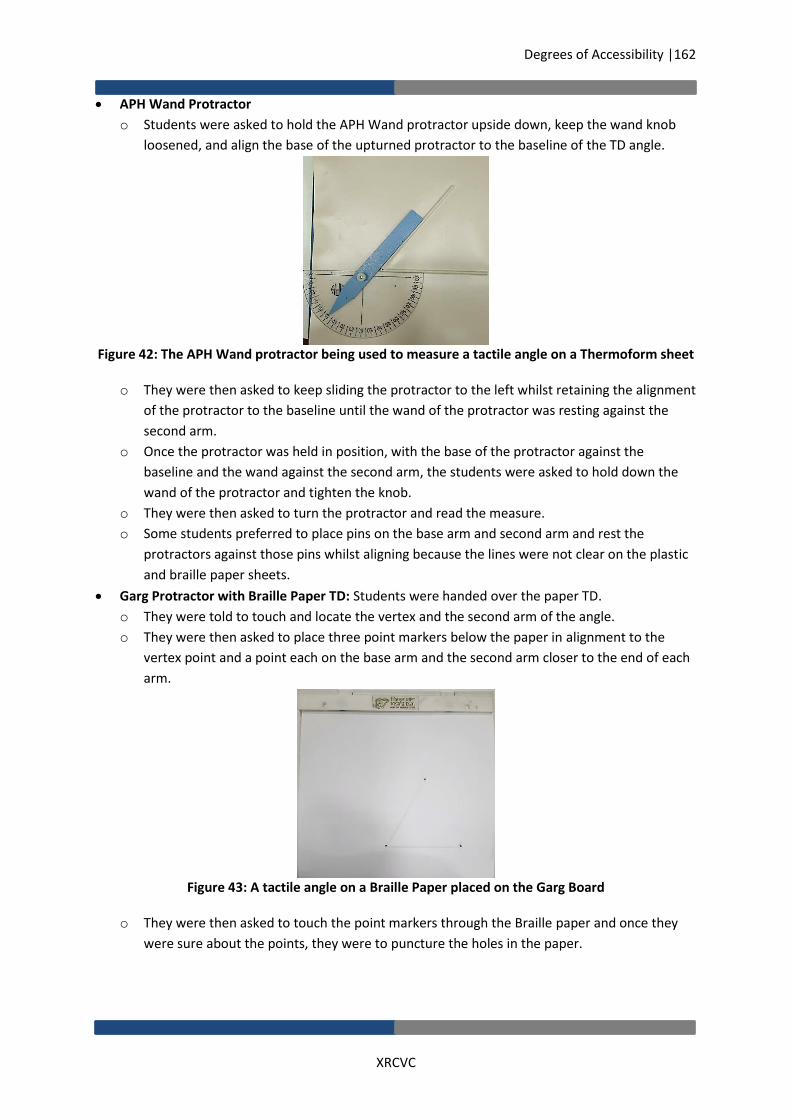
Degrees of Accessibility |162
XRCVC
APH Wand Protractor
o Students were asked to hold the APH Wand protractor upside down, keep the wand knob
loosened, and align the base of the upturned protractor to the baseline of the TD angle.
Figure 42: The APH Wand protractor being used to measure a tactile angle on a Thermoform sheet
o They were then asked to keep sliding the protractor to the left whilst retaining the alignment
of the protractor to the baseline until the wand of the protractor was resting against the
second arm.
o Once the protractor was held in position, with the base of the protractor against the
baseline and the wand against the second arm, the students were asked to hold down the
wand of the protractor and tighten the knob.
o They were then asked to turn the protractor and read the measure.
o Some students preferred to place pins on the base arm and second arm and rest the
protractors against those pins whilst aligning because the lines were not clear on the plastic
and braille paper sheets.
Garg Protractor with Braille Paper TD: Students were handed over the paper TD.
o They were told to touch and locate the vertex and the second arm of the angle.
o They were then asked to place three point markers below the paper in alignment to the
vertex point and a point each on the base arm and the second arm closer to the end of each
arm.
Figure 43: A tactile angle on a Braille Paper placed on the Garg Board
o They were then asked to touch the point markers through the Braille paper and once they
were sure about the points, they were to puncture the holes in the paper.

Degrees of Accessibility |163
XRCVC
o They were then asked to remove the paper and take the Garg protractor and place the
central immobilization hole on the vertex point with the fixed line marker resting on the
base arm point marker.
Figure 44: The Garg protractor positioned on the point markers on the Garg Board.
o They were then asked to place another line marker from the vertex point to the point
marker on the second arm.
Figure 45: The Garg protractor positioned on the point markers on the Garg Board, with an extra
line marker for the second arm.
o They were then asked to read the measurement starting at the fixed line marker up to the
second arm line marker. In order to be sure of the measurement, they were asked to read
the markings before and after the placed line marker on the second arm.
Figure 46: The Garg protractor with a line marker set at 45 degrees hiding the relevant tactile
marking under it

Degrees of Accessibility |164
XRCVC
Skill 5: Constructing a Circle For teaching the students the skill of constructing a circle, the following steps were followed:
a. Explaining the concept of a circle
b. Orientation to and use of each compass to construct a circle
c. Finding the area to draw
d. Setting/fixing the radius and drawing the circle
a. Explaining the Concept of a Circle:
Students were asked if they knew what a circle was, and were encouraged to draw a circle.
Once their circle was drawn, they were shown a perfect circle drawn by the instructor. The circle
had a clearly-marked centre point and students were encouraged to see both the circles.
They were explained the concept of a circle as being a shape with a single centre point and
equidistant radius from the centre point to any point on the circumference.
They were also explained that in this skill, they were going to learn how to draw circles of
different radii and that the parts of the circle that will be worked with in this skill are the centre,
the radius and the circumference of the circle.
b. Orientation to and Use of each Compass to construct a Circle
Students were oriented to use the Classmate Compass in combination with the APH Clip
Ruler, the RNIB Ruler, the WT Ruler and the Squirrel Ruler; the WT ruler as a compass, the
APH Compass and the Garg Compass.
Classmate Compass + RNIB Ruler/APH Clip Ruler/WT Ruler/Squirrel Ruler
o Students were given the compass in their hands, and first orientated to the sharp pin of
the first leg and instructed to always be careful when using this leg.
o They were oriented to the two legs, one with the pin and the second leg with the pen
loaded on the same. They were not instructed in loading the pen as that was pre-loaded
for them to save time.
o There were told to move the legs to see how they can be pulled apart and pushed
together.
o They were also oriented to the knob at the top where the two legs joined. They were
asked to loosen and tighten the knob, and understand how the legs are immobilised
when the knob is tightened.
WT Ruler as a Compass
o Students were given the WT ruler in their hand and instructed that this time we would
be using this ruler as a compass.
o In order for the ruler to be used as a compass, they were told that they semi-circle end
of the ruler and the hole therein would be used as the first leg, and the holes down the
middle of the ruler corresponding to the tactile markings would be used to insert the
stylus which would be used as the second leg.
APH Compass
o Students were given the compass in their hands and first orientated to the sharp tip of
the fixed leg and instructed to always be careful about the same.
o They were oriented to the two legs, one with the point tip and the other with the spur
wheel.

Degrees of Accessibility |165
XRCVC
o There were told to move the legs to see how the pointed tip leg was fixed whereas the
leg with the spur wheel could slide along the horizontal bar of the compass.
o They were also then oriented to the screw at the stop of the spur wheel leg. They were
asked to loosen and tighten the screw, and understand how the legs are immobilised
when the knob is tightened.
o They were also oriented to the measurement markings on the two sides of the
horizontal bar of the compass. Both the sides had long marks and short marks, but the
marks on one of the sides were more spread out, indicating it was the inches side and
the other side was the cm side. For the purpose of the research, the cm side was used.
Garg Compass
Figure 47: Circle markers of different sizes from the Garg Geometry Kit
o Students were given the circle markers to feel.
o They were asked to explore that each circle marker was of different size and had a
braille reading of the measurement of the marker.
o They were also oriented to the central immobilisation hole on the circle marker
c. Finding the Area to Draw
Classmate Compass , WT Ruler as Compass, APH Compass
o Students were asked to explore their immobilized sheet and find free space to draw on.
o They were asked to locate the centre of the page. Help was given to those who struggled
at this stage.
Garg Compass
o Students were asked to find free space on top of the paper and the centre point on top
of the paper.
o After this students were asked to lift the paper and bend it slightly near the clip so that it
would not fall back and asked for corresponding free space on the board.
Figure 48: A point marker placed at the centre of the Garg board

Degrees of Accessibility |166
XRCVC
d. Setting/fixing the Radius & Drawing the Circle
Classmate Compass + RNIB Ruler/ APH Clip Ruler/ Worth Trust Ruler/Squirrel Rulers
o Students were asked to rest the ruler on the immobilization pins on the bottom of the
sheet. Specifically for the RNIB ruler with the groove side up and with the cm side up for
the APH clip ruler.
o The method of adjusting and resting the compass legs against the ruler markings for
each ruler is detailed below:
Figure 49: The Classmate compass being aligned for a specific measurement with the RNIB ruler on
the Exam board
For the RNIB ruler: They were instructed to take the pin leg of the compass and place it in
the groove of any extra-long mark/ other mark. They were also instructed to always press
down the leg completely into the mat. They had to read on the ruler, the measurement
given to them, and place the pen leg of the compass at the groove of the desired mark.
For the APH Clip ruler: They were instructed to take the pin leg of the compass and place it
on any long mark/ other mark of the ruler. They were also instructed to always press down
the leg completely into the mat. They had to read on the ruler, the measurement given to
them, and place the pen leg of the compass at that mark.
Figure 50: The Classmate compass being aligned for a specific measurement with the APH clip ruler
on the Exam board
For the WT ruler: They were instructed to take the pin leg of the compass and place it in the
centre hole next to on any long mark/ other mark. They were also instructed to always press
down the leg completely into the mat. They were then instructed to read on the ruler, the
measurement given to them, and place the pen leg of the compass at the centre hole of that
mark.

Degrees of Accessibility |167
XRCVC
Figure 51: The Classmate compass being aligned for a specific measurement with the WT ruler on
the Exam board
For the Squirrel ruler: They were instructed to set the measurement on the ruler. Once the
measurement was set, they were instructed to place the two legs of the compass at the two
clip edges of the ruler, whilst holding down the ruler and ensuring that the clip did not
move. They were also instructed to keep the first leg pressed fully down into the mat.
Figure 52: The Classmate compass being aligned for a specific measurement with the Squirrel ruler
on the Exam board
o They were instructed to do the above whilst holding down the ruler and the first leg.
Figure 53: The Classmate compass being aligned for a specific measurement with the Squirrel ruler
on the Exam board
o After they had finished placing the compass to the right measurement, they were asked
to tighten the knob by being careful to not press the legs together whilst tightening the
knob.
o For students who struggled in pulling out the compass to the right measurement with
one hand, they were instructed to first keep the compass fully stretched, and after fixing
the first leg to the start point, push back the compass to the right measurement mark.

Degrees of Accessibility |168
XRCVC
o Students were asked to bring the pin leg of the compass to the centre, and press it down
completely into the mat. They were instructed to ensure that they were holding the
compass lightly and were not pushing/moving the legs of the compass.
o After they had pressed down the first leg, they were asked to hold the other leg of the
compass from the side and not on top of the leg as the latter could lead to the leg
getting pushed back towards the pin leg.
o They were then instructed to turn the mat whilst holding down the second leg of the
compass on the sheet such that the pen would make the drawing on the sheet.
o As they drew, they were asked to check the sheet for the mark being drawn, and to stop
when the circle was complete.
WT Ruler as a Compass
o Students were asked to place the ruler’s semi-circle end at the centre of the page and
immobilize the ruler by placing a pin through its hole.
o They were then instructed to move the ruler 360 degrees, and in case the ruler clashed
with either the exam board clip or the immobilization pins placed below, they were
asked to remove the clip/immobilization pins.
o They were asked to measure the radius, and place the stylus in the hole corresponding
to the measurement, and draw the circle by moving the stylus along with the ruler
around to make the circle.
Figure 54: The WT ruler being used as a compass to draw a circle
o They could either turn the board whilst doing this or turn the ruler whilst keeping the
board straight.
o Having the centre immobilised was helpful to ensure a fixed single centre.
APH Compass
Figure 55: A circle being drawing with the APH compass

Degrees of Accessibility |169
XRCVC
o Students were asked to fix the measurement on the compass by counting on the cm side
and by bringing the spur wheel leg to the precise measurement mark. They were
instructed to count the first long mark as 1. In order to do the same accurately, they
were asked to keep their fingers in the dent of the final tactile mark and to bring the
spur wheel leg just next to the finger.
o They were then asked to tighten the screw to immobilise the second arm.
o They were asked to bring the pointed leg of the compass to the centre and press it down
completely, and keep one hand holding it down all the time.
o They were asked to hold the second leg of the compass and turn the compass whilst
holding down the second leg of the compass on the sheet.
o As they turned the compass, they were also instructed to exchange their hands holding
the first leg and the second leg to make drawing easy as the compass turned 360
degrees.
o Since this compass had a spur wheel the drawing happened on the reverse side.
Garg Compass
Figure 56: A circle being drawing with the Garg compass/Circle marker
o Students were asked to place a point marker at the centre point on the board,
corresponding to the centre point found on the paper.
o They were asked to press the paper down and puncture the hole and lift the paper back
up.
o They were asked to identify a Circle Marker of the desired radius, and instructed to place
it on the Point marker completely flat while ensuring that the point marker had not
moved.
o They were then asked to place the paper back on the Point marker and Circle marker
whilst being careful that the Point marker and Circle marker did not move under the
paper.
o They were asked to gently press the paper down with their hands along the outer edge
of the Circle marker.
o Then, using the Garg stylus, they were asked to draw over the Circle marker. Those who
preferred to turn the board whilst drawing were allowed to do so.

Degrees of Accessibility |170
XRCVC
Skill 6: Constructing/Cutting Arcs For teaching them concept of arcs, the following steps were followed:
a. Explaining the concept of arcs in link with line bisection as an example
b. Orientation to and use of each compass to cut arcs for line bisection
c. Orientation to line segments and measurement
d. Fixing the compass legs to the end points of line segments and setting the radius
e. Drawing the arc
f. Finding the intersecting points and drawing the bisector
a. Explaining the concept of Arcs in link with Line Bisection as an example
Students were given an explanation of what an arc is with line bisection as an example.
Students were explained what an arc is. They were told that an arc is a part of the circumference
of a circle, and like a circle, an arc would have a fixed point of drawing.
They were explained that arcs are used for various functions in geometry, and in this skill, we
would learn how to use the different compasses for drawing arcs for a line bisector.
They were explained that line bisection means cutting the line segment into two equal halves.
b. Orientation to and Use of each Compass to Cut Arcs for Line Bisection
Since the students were already oriented to the compasses in Skill 5, the same was not repeated
here.
Since the Garg Arc Markers were new, the students were oriented to them. Some students in
the research used the circle markers instead.
Figure 57: Arc markers of different sizes from the Garg Geometry Kit
Students were asked to move their hands over the arc marker and find the number of arcs, the
centre hole and the braille readings on the same.
They were explained to use the braille signs and to locate the arc corresponding to that
measurement.
c. Orientation to Line Segments and Measurement
For the purpose of research in order to save time, they were not asked to draw the line segment.
They were given a sheet with a pre-drawn line segment and informed of its length.
They were also informed that in order to draw a line bisector they must set the radius of the
compass to more than half but less than the full the length of the segment.

Degrees of Accessibility |171
XRCVC
d. Fixing the Compass Legs to the End Points of Line Segments and Setting the Radius
Classmate Compass
o Students were asked to loosen the compass knob and bring the pin leg of the compass to
either of the end points of the line segment, and press it down completely.
o They were then asked to set the radius by judging the line length and placing the pen leg of
the compass up to more than half but less than the full length of the line segment. Once
they had set the radius, they were asked to tighten the compass knob and fix the compass
legs to position.
Figure 58: The radius of the Classmate compass being set
APH Compass
o Students were asked to fix the measurement on the APH compass by counting on the cm
side and bringing the spur wheel leg to the mark at which the measurement completes more
than half but less than the full length of the line segment, or take a guess along the line
segment by placing the first leg down at the end point and adjusting the second leg along
the line segment.
Figure 59: The radius of the APH compass being set
o If they were using the pre-counted measurement method, they were instructed to count the
first long mark as 1. In order to do the same accurately, they were asked to keep their
fingers in the dent of the final tactile mark, and to bring the spur wheel leg just next to the
finger.
o They were then asked to tighten the screw to immobilise the second leg at the desired
measure.

Degrees of Accessibility |172
XRCVC
e. Drawing the Arc
Figure 60: Cutting arcs
Students were asked to bring the point leg of the compass to either of the end points and press
it down completely, and keep one hand holding it down all the time.
They were asked to hold the second leg of the compass, and turn the compass whilst holding
down the second leg of the compass on the sheet.
They were asked to make an extended arc on the side of the line segment such that the arc is a
semi-circle passing through the line segment.
They were asked to repeat this from the other end of the line segment as well.
Since the APH compass had a spur wheel the drawing happened on the reverse side.
f. Finding the intersecting points and drawing the bisector
Figure 61: Line bisection on the Exam board
Students were asked feel the entire drawing and identify the line segment, the area above and
below it, the parts at which the arcs cut the line segment and the points of intersection of the
arcs above and below the line segment.
Students were asked to place a pin at the intersection points of the arcs both above and below
the line segment.
They were then asked to place the ruler resting against the two pins at the intersection points
and join the points with a stylus whilst holding down the ruler.
They were then asked to measure and see the line segment on either sides of the line bisector to
check whether it was accurately bisected.
Since the WT ruler as a compass and the Garg compass used a different system steps d, e, and f
happened for them in a slightly different variation which are listed below.

Degrees of Accessibility |173
XRCVC
WT Ruler as a Compass: Fixing the Compass Legs to the end points of line segments + Setting
the Radius + Drawing the Arc
o Students were asked to place a pin in the ruler’s semi-circle end, and bring the same to
either of the end points, locate the exact point and immobilize the ruler by pressing down
the pin.
o They were then instructed to take a measurement on the ruler for the radius based on the
length of the line segment (more than half but less than the full length of the line segment),
and keep in mind the measurement.
o They were asked to place a stylus at the hole of the selected measurement, and they were
asked to make a full arc on the side of the line segment such that the arc is a proper semi-
circle passing through the line segment.
o They were asked to repeat this from the other end of the line segment as well.
Garg Compass: Fixing Compass Leg to end points of line segment + Setting the Radius +
Drawing the Arc :
Figure 62: Line bisection with the Garg kit
o Students were asked to place two point markers on the board corresponding to the end
points found on the paper.
o They were asked to press the paper down and puncture the holes and lift the paper back.
o They were asked to identify and place the arc marker/circle marker of the desired radius and
place it on the point marker fully flat ensuring that the point marker did not move.
o They were asked to select the arc marker/circle marker based on either selecting the marker
of a measurement more than half but less than the full length of the line segment, or they
were asked to put the arc markers/circle marker on one of the end points and make a
judgement in reference to the second point marker.
o They were asked to then place the paper back on the arc/circle markers whilst being careful
that the point marker and arc/circle markers did not move under the paper.
o They were asked to gently press down the paper along the outer edge of the circle marker or
the desired arc circumference of the arc marker.
o Using the stylus, they were asked to draw over the same using the Garg stylus. Those who
preferred turned the board whilst drawing.

Degrees of Accessibility |174
XRCVC
Garg Compass: Finding the intersecting points and drawings the bisector
Figure 63: Line bisection with the Garg kit
o Students were asked feel the entire drawing and identify the line segment, the area above
and below it, the parts that the arcs cut the line segments and points of intersection of the
arcs above and below the line segment.
o Students were asked to place a point marker under the Braille paper corresponding to the
intersection points of the arcs both above and below the line segment.
o They were then asked to place the paper down, and puncture holes at the point makers.
o They were asked to lift the paper, and place a line marker over the two point markers, place
the paper back down, and draw over the line marker connecting the two points.

Degrees of Accessibility |175
XRCVC
REFERENCES Brawand, A., Johnson N., (2016). Effective Methods for Delivering Mathematics Instruction to
Students with Visual Impairments. Journal of Blindness Innovation and Research, 6(1). Retrieved
from https://nfb.org/images/nfb/publications/jbir/jbir16/jbir060101.html
Buzzi, M. C., Buzzi, M., Leporini, B., and Senette, C. (2015, September). Playing with geometry: a
multimodal android app for blind children. In Proceedings of the 11th Biannual Conference on
Italian SIGCHI Chapter (pp. 134-137). ACM.
Clements, D. H., and Battista, M. T. (1992). Geometry and spatial reasoning. Handbook of research
on mathematics teaching and learning, 420-464.
Dion, M., Hoffmann, K., and Matter, A. (2000). Teacher's manual for adapting science experiments
for blind and visually impaired students. Worcester Polytechnic Institute.
Kamel, H. M., and Landay, J. A. (1999, May). The integrated communication 2 draw (IC2D): a drawing
program for the visually impaired. In CHI'99 Extended Abstracts on Human Factors in Computing
Systems (pp. 222-223). ACM.
Kamel, H. M., and Landay, J. A. (2000, November). A study of blind drawing practice: creating
graphical information without the visual channel. In Proceedings of the fourth international
ACM conference on Assistive technologies (pp. 34-41). ACM.
Karshmer, A. I., and Bledsoe, C. (2002, July). Access to mathematics by blind students.
In International Conference on Computers for Handicapped Persons (pp. 471-476). Springer,
Berlin, Heidelberg.
León, L., Martini, L. C., and Moreno-Chaparro, C. (2016). Tools for Teaching Mathematical Functions
and Geometric Figures to Tactile Visualization through a Braille Printer for Visual Impairment
People. Journal of Systemics, 14(2), 7-10.
Moyer, P. S. (2001). Are we having fun yet? How teachers use manipulatives to teach
mathematics. Educational Studies in mathematics, 47(2), 175-197.
Osterhaus S.A. (2019). Teaching Strategies. Retrieved from https://www.tsbvi.edu/teaching-
strategies
Petit, G., Dufresne, A., Levesque, V., Hayward, V., and Trudeau, N. (2008, October). Refreshable
tactile graphics applied to schoolbook illustrations for students with visual impairment.
In Proceedings of the 10th international ACM SIGACCESS conference on Computers and
accessibility (pp. 89-96). ACM.
Pradhan, S., and Samanta, M. (2018). Use of Assistive Technology in blind schools of West Bengal: A
comparative study. Retrieved from
http://digitalcommons.unl.edu/cgi/viewcontent.cgi?article=5088andcontext=libphilprac
ROBINSON, T. (2007). The Progressive Step Method for Teaching Geometry Constructions to
Students with Visual Impairments. The Japanese Journal of Special Education, 44(6), 543-550.

Degrees of Accessibility |176
XRCVC
Rouzier, S., Hennion, B., Segovia, T. P., and Chêne, D. (2004). Touching geometry for visually
impaired pupils. EuroHaptics Proceedings, Munich, Germany, 104-109.
Tanti, M. (N.D.) Teaching Mathematics to a Blind Student - A Case Study. Retrieved from https://socialsciences.exeter.ac.uk/education/research/centres/stem/publications/pmej/pome20/Mariella%20Tanti%20Teaching%20Mathematics%20to%20a%20Blind%20Student%20-%20%20%20%20%20%20A%20Case%20Study.pdf

Xavier’s Resource Centre for the Visually Challenged (XRCVC) St. Xavier’s College, 5 Mahapalika Marg, Mumbai 400001
+91-22-22623298/22626329 | [email protected] | www.xrcvc.org
This report is based on research conducted by the Xavier’s Resource Centre for the Visually
Challenged (XRCVC) as part of the Great Eastern CSR Foundation’s
Inclusive Education Project