Defining a Wireless Sensor Network Management Protocol
12
Defining a Wireless Sensor Net work Management Protocol Fabr ´ ıcio A. Silva 2 , Linnyer B. Ruiz 1 , Thais R. M. Braga 2 , Jos´ e Marcos S. Nogueira 2, 3 and Antonio A. F. Loureiro 2 1 Department of Electrical Engineering 2 Department of Computer Science Federal University of Minas Gerais Av. Antˆ onio Carlos, 6627, CEP:31279-010 Belo Horizonte, Minas Gerais, Brasil 3 In sabbatical period at universities of Evry and UPMC/Paris6/LIP6, France {fasilva,linnyer,thaisrb,jmarcos,loureiro}@dcc.ufmg.br Abstract. Wireless Sensor Networks (WSNs) are a special kind of mo- bile ad hoc network with particular characteristics, like for example, the severe computational and energy resources restrictions presented by their elements. It is interesting to use management services and functions in this kind of network with the goal of promoting resource productivity and quality of the provided services.Anevaluation performed in order to verify the applicability of management protocols developed for tradi- tional networks in WSNs has shown that they are not suitable, given the specific features of these networks. In this work, we aim to define a WSN management protocol adherent to the particularities of this kind of net- work, allowing them to be managed without resources overconsumption. Keywords: wireless sensor networks management, management protocol, Manna architecture. 1 Introduction Wireless Sensor Networks (WSNs) present several specific characteristics that differentiate them from traditional networks [1]. This kind of network is generally comprised of hundreds to thousands of devices, called sensor nodes, which tend to be designed with small dimensions, imposing severe hardware and software restrictions. A sensor node is comprised of energy source, transceptor, proces- sor, memory and one or more sensor devices. The energy source is considered the most important resource, since all other components depend on it to operate properly. The WSNs application environments are, in general, inhospitable or difficult to access, making local maintenance performed by technicians hard or even impossible. These and other characteristics lead to the necessity of develop- ment of solutions to this kind of network that present low energy, processing and LANOMS 2005 - 4th Latin American Network Operations and Management Symposium 39
-
Upload
independent -
Category
Documents
-
view
0 -
download
0
Transcript of Defining a Wireless Sensor Network Management Protocol

Defining a Wireless Sensor Network
Management Protocol
Fabrıcio A. Silva2, Linnyer B. Ruiz1, Thais R. M. Braga2,Jose Marcos S. Nogueira2,3 and Antonio A. F. Loureiro2
1 Department of Electrical Engineering2 Department of Computer ScienceFederal University of Minas Gerais
Av. Antonio Carlos, 6627, CEP: 31279-010Belo Horizonte, Minas Gerais, Brasil
3 In sabbatical period at universities of Evry and UPMC/Paris6/LIP6, France{fasilva,linnyer,thaisrb,jmarcos,loureiro}@dcc.ufmg.br
Abstract. Wireless Sensor Networks (WSNs) are a special kind of mo-bile ad hoc network with particular characteristics, like for example, thesevere computational and energy resources restrictions presented by theirelements. It is interesting to use management services and functions inthis kind of network with the goal of promoting resource productivityand quality of the provided services. An evaluation performed in orderto verify the applicability of management protocols developed for tradi-tional networks in WSNs has shown that they are not suitable, given thespecific features of these networks. In this work, we aim to define a WSNmanagement protocol adherent to the particularities of this kind of net-work, allowing them to be managed without resources overconsumption.
Keywords: wireless sensor networks management, management protocol,Manna architecture.
1 Introduction
Wireless Sensor Networks (WSNs) present several specific characteristics thatdifferentiate them from traditional networks [1]. This kind of network is generallycomprised of hundreds to thousands of devices, called sensor nodes, which tendto be designed with small dimensions, imposing severe hardware and softwarerestrictions. A sensor node is comprised of energy source, transceptor, proces-sor, memory and one or more sensor devices. The energy source is consideredthe most important resource, since all other components depend on it to operateproperly. The WSNs application environments are, in general, inhospitable ordifficult to access, making local maintenance performed by technicians hard oreven impossible. These and other characteristics lead to the necessity of develop-ment of solutions to this kind of network that present low energy, processing and
LANOMS 2005 - 4th Latin American Network Operations and Management Symposium 39

communication resources usage. Therefore, the proposal of a WSN managementprotocol should also consider all the restrictions imposed by these networks.
The goal of this work is to define a management protocol for the applica-tion layer of WSNs specific protocol stack, which will be used initially by theManna architecture [2], proposed to the management of this kind of network.For this reason, the protocol will be named MannaNMP (Manna Network Man-
agement Protocol). MannaNMP allows users to request network information,attribute values to variables and receive notifications in case some event occurs.With MannaNMP, it will also be possible to implement distributed managementstrategies.
The remainder of this paper is organized as follows: Section 2 presents thecharacterization of the problem considered in this work. Section 3 contains themain design requirements considered to the MannaNMP specification. Section 4presents the specification of the proposed protocol. Section 5 illustrates the Man-agement Information Base (MIB) proposed to WSNs management. Finally, Sec-tion 6 presents the conclusions and future work.
2 Characterizing the Problem
Given the characteristics of WSNs, it is interesting to perform an evaluationof the management protocols developed for traditional networks, identifyingwhether or not it is viable to implement them in networks with energy, hardwareand software restrictions. For this reason, the traditional network managementprotocol, SNMP [3] (Simple Network Management Protocol), and the protocolproposed to the management of wireless ad hoc networks, ANMP [4] (Ad hocNetwork Management Protocol), were studied, and their implementation viabil-ity on WSNs verified.
Requirements Fusion [5] InterNiche InterNiche SMX[7]NicheLite [6] NicheStack [6]
Memory 90 12,8 42,4 37,4 (x86)TCP/IP (KB) 48 (PowerPC)
Memory 57 52 52 35,7 (x86)SNMP (KB) 40 (PowerPC)
Memory 147 64,8 94,4 73.1 (x86)Total (KB) 88 (PowerPC)
Processor Independent x86 x86 x86 or PowerPC
Other Details - Incomplete Complete SNMPv2Stack Stack Version.
Table 1. Characteristics of embedded SNMP implementations.
40 LANOMS 2005 - 4th Latin American Network Operations and Management Symposium
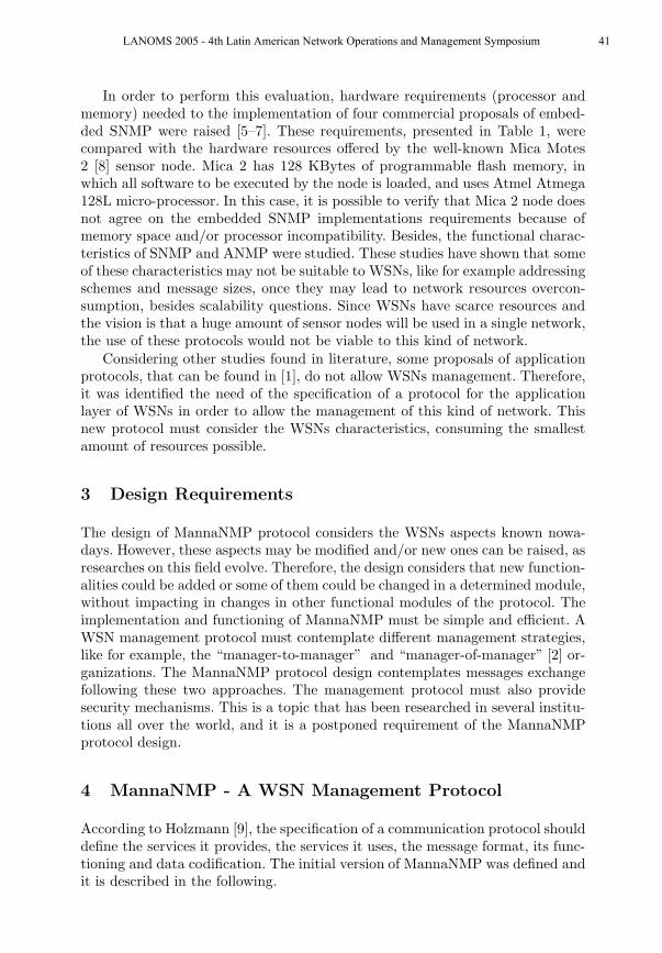
In order to perform this evaluation, hardware requirements (processor andmemory) needed to the implementation of four commercial proposals of embed-ded SNMP were raised [5–7]. These requirements, presented in Table 1, werecompared with the hardware resources offered by the well-known Mica Motes2 [8] sensor node. Mica 2 has 128 KBytes of programmable flash memory, inwhich all software to be executed by the node is loaded, and uses Atmel Atmega128L micro-processor. In this case, it is possible to verify that Mica 2 node doesnot agree on the embedded SNMP implementations requirements because ofmemory space and/or processor incompatibility. Besides, the functional charac-teristics of SNMP and ANMP were studied. These studies have shown that someof these characteristics may not be suitable to WSNs, like for example addressingschemes and message sizes, once they may lead to network resources overcon-sumption, besides scalability questions. Since WSNs have scarce resources andthe vision is that a huge amount of sensor nodes will be used in a single network,the use of these protocols would not be viable to this kind of network.
Considering other studies found in literature, some proposals of applicationprotocols, that can be found in [1], do not allow WSNs management. Therefore,it was identified the need of the specification of a protocol for the applicationlayer of WSNs in order to allow the management of this kind of network. Thisnew protocol must consider the WSNs characteristics, consuming the smallestamount of resources possible.
3 Design Requirements
The design of MannaNMP protocol considers the WSNs aspects known nowa-days. However, these aspects may be modified and/or new ones can be raised, asresearches on this field evolve. Therefore, the design considers that new function-alities could be added or some of them could be changed in a determined module,without impacting in changes in other functional modules of the protocol. Theimplementation and functioning of MannaNMP must be simple and efficient. AWSN management protocol must contemplate different management strategies,like for example, the “manager-to-manager” and “manager-of-manager” [2] or-ganizations. The MannaNMP protocol design contemplates messages exchangefollowing these two approaches. The management protocol must also providesecurity mechanisms. This is a topic that has been researched in several institu-tions all over the world, and it is a postponed requirement of the MannaNMPprotocol design.
4 MannaNMP - A WSN Management Protocol
According to Holzmann [9], the specification of a communication protocol shoulddefine the services it provides, the services it uses, the message format, its func-tioning and data codification. The initial version of MannaNMP was defined andit is described in the following.
LANOMS 2005 - 4th Latin American Network Operations and Management Symposium 41

4.1 Provided Services
The protocol must offer services that will be used by the upper layer of theprotocol stack. Once we are dealing with an application layer protocol, it is theuser (observer) that will use its services. MannaNMP should promote to its usera mechanism for management message exchange. Users will be able to requestnetwork information, attribute values to variables and receive notifications incase some event occurs.
4.2 Used Services
The application layer protocol will use the services provided by the immediatelower layer. There are available in literature, proposals of protocols for the trans-port, network and MAC layers of WSNs, as those presented in [1] and otherspublished more recently. However, until now, there is not a standard WSN proto-col stack. Besides, a set of protocols can be efficient for certain applications, butinefficient for others. Once the question of definition of a WSN protocol stack isstill an open topic, the MannaNMP design will consider only the aspects relatedto the application level.
4.3 Message Format
The vocabulary and message format of MannaNMP are very similar to SNMPones, excepting for some small details, like for example, the orchestrationmechanism that allows the addition of a small delay in message sending. Thissimilarity will facilitate the implementation process of a Proxy Agent thatpresents the functionality of mapping MannaNMP messages into messages of adistinct protocol, and vice versa. Figure 1 illustrates the headers of MannaNMPmessages. The semantics of the messages will be presented in Section 4.4. Thedefinition of the message format is described below:
PDU = {Get, Set, Response, Trap, Inform};Initially, these five message types were defined. In case it is necessary, othersmay be included in the future.
VariableBindings = {object 1 id, value 1,.........., object n id, value n};This construction contains a list of objects identifiers and their respectivevalues. The object identifiers are organized in a tree scheme and are describedin Section 5.
Get = {PDU Type, Requisition Identifier, Orchestrated Delay, Agent Identi-
fier, VariableBindings};PDU Type indicates that this is a Get message. Requisition Identifier identifiesa requisition solely, in order to be possible to verify an answer or an errorindication. The Orchestrated Delay indicates whether or not the entity shoulddelay to send the requisition answer. More details on this mechanism are
42 LANOMS 2005 - 4th Latin American Network Operations and Management Symposium
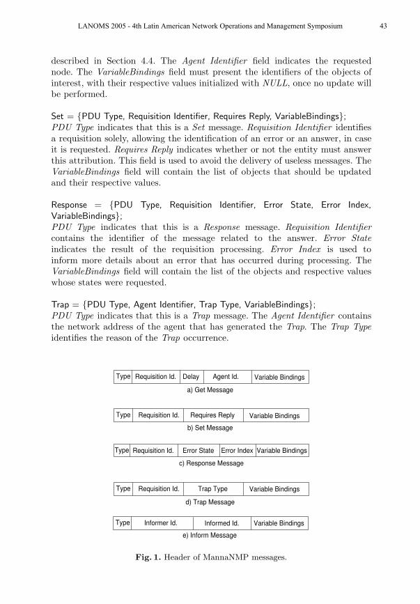
described in Section 4.4. The Agent Identifier field indicates the requestednode. The VariableBindings field must present the identifiers of the objects ofinterest, with their respective values initialized with NULL, once no update willbe performed.
Set = {PDU Type, Requisition Identifier, Requires Reply, VariableBindings};PDU Type indicates that this is a Set message. Requisition Identifier identifiesa requisition solely, allowing the identification of an error or an answer, in caseit is requested. Requires Reply indicates whether or not the entity must answerthis attribution. This field is used to avoid the delivery of useless messages. TheVariableBindings field will contain the list of objects that should be updatedand their respective values.
Response = {PDU Type, Requisition Identifier, Error State, Error Index,
VariableBindings};PDU Type indicates that this is a Response message. Requisition Identifier
contains the identifier of the message related to the answer. Error State
indicates the result of the requisition processing. Error Index is used toinform more details about an error that has occurred during processing. TheVariableBindings field will contain the list of the objects and respective valueswhose states were requested.
Trap = {PDU Type, Agent Identifier, Trap Type, VariableBindings};PDU Type indicates that this is a Trap message. The Agent Identifier containsthe network address of the agent that has generated the Trap. The Trap Type
identifies the reason of the Trap occurrence.
Type Requisition Id. Delay Variable BindingsAgent Id.
a) Get Message
Type Requisition Id. Requires Reply Variable Bindings
b) Set Message
Type Requisition Id. Variable BindingsError State Error Index
c) Response Message
Type Requisition Id. Trap Type Variable Bindings
d) Trap Message
Type Variable BindingsInformer Id.
e) Inform Message
Informed Id.
Fig. 1. Header of MannaNMP messages.
LANOMS 2005 - 4th Latin American Network Operations and Management Symposium 43

Inform = {PDU Type, Informer Identifier, Informed Identifier, VariableBind-
ings};PDU Type indicates that this is an Inform message. The Informer Identifier
field indicates the identifier of the entity that is sending the message and thefield Informed Identifier will contain the identifier of the node that is themessage’s destination.
Trap Type = {Energy, Topology, Security, Fault, Administrative};Initially, these will be the Traps types allowed. However, this list can beenlarged according to the necessities of the designed management solution.
4.4 Message Semantics
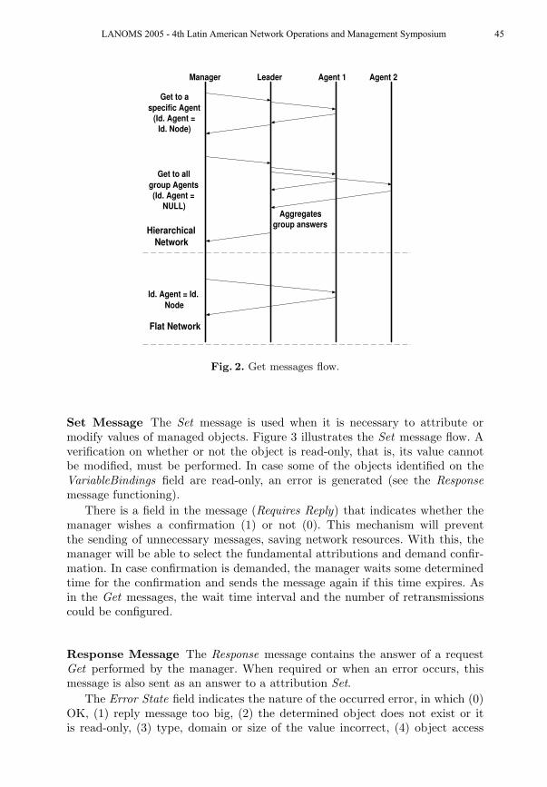
Get Message The Get message is used by the observer in order to requestinformation about managed objects. This information corresponds to the valueof an object in a given period of time. Figure 2 illustrates the Get messageflow. The manager waits for the answer during a determined period of time(timeout). In case this timeout expires, the message is sent again. The timeoutvalue could be configured, depending on the network characteristics. The numberof retransmission could also be configured in order to avoid messages to beretransmitted several times.
When the network is hierarchical, some aspects must be considered. If theAgent Identifier field of the message presents the NULL value, it means thatthe group leader should request information from all group members. In theopposite case, this field will correspond to the identifier of the node that themanager is interested in. In the first case, the leader should wait some time inorder to aggregate all received answers into a single message. When the managerwants answers coming from all network groups, it should send a message withthe BROADCAST address.
When the answers are requested from several network nodes simultaneously,the Orchestrated Delay field of the message initialized with value 1 will indicatethat nodes should wait for some random time interval before sending theiranswers. This process will decrease messages collision and loss, since it decreasesthe probability of nodes answering at the same time. The time interval shouldbe calculated through the following formula defined in [10]:
Delay = KH(h2 − (2h − 1)r),
where h is the distance in number of hops from the source of the mes-sage, r is a random number such that 0 < r <= 1, and H is a constant thatreflects the network per hop delay. In order to incorporate processing and queuewaiting delays, the compensation constant K is used. The constants K and H
are combined and can be adjusted.
44 LANOMS 2005 - 4th Latin American Network Operations and Management Symposium
Manager Leader Agent 1
Aggregatesgroup answers
Agent 2
Get to aspecific Agent
(Id. Agent =Id. Node)
Get to allgroup Agents(Id. Agent =
NULL)
HierarchicalNetwork
Flat Network
Id. Agent = Id.Node
Fig. 2. Get messages flow.
Set Message The Set message is used when it is necessary to attribute ormodify values of managed objects. Figure 3 illustrates the Set message flow. Averification on whether or not the object is read-only, that is, its value cannotbe modified, must be performed. In case some of the objects identified on theVariableBindings field are read-only, an error is generated (see the Response
message functioning).
There is a field in the message (Requires Reply) that indicates whether themanager wishes a confirmation (1) or not (0). This mechanism will preventthe sending of unnecessary messages, saving network resources. With this, themanager will be able to select the fundamental attributions and demand confir-mation. In case confirmation is demanded, the manager waits some determinedtime for the confirmation and sends the message again if this time expires. Asin the Get messages, the wait time interval and the number of retransmissionscould be configured.
Response Message The Response message contains the answer of a requestGet performed by the manager. When required or when an error occurs, thismessage is also sent as an answer to a attribution Set.
The Error State field indicates the nature of the occurred error, in which (0)OK, (1) reply message too big, (2) the determined object does not exist or itis read-only, (3) type, domain or size of the value incorrect, (4) object access
LANOMS 2005 - 4th Latin American Network Operations and Management Symposium 45

Manager Leader Agent 1 Agent 2
Set that requiresreply (Requires
Reply = 1)Verifies if
requires reply
Set that doesnot requires
reply (RequiresReply = 0)
Verifies ifrequires replyHierarchical
Network
Flat Network
Set thatrequires reply
(RequiresReply = 1)
Verifies ifrequires reply
Set that doesnot requires
reply (RequiresReply = 0)
Verifies ifrequires reply
Fig. 3. Set messages flow.
denied for security reasons, (5) some information is not available for some otherreason.
In case this field is different from zero, the field Error Index provides ad-ditional information, indicating which variable of the list caused the exception.When no error occurs, the field VariableBindings will contain the requested ob-jects with their respective values.
Trap Message The Trap message is asynchronous and it is sent when someevent programmed by the network designer occurs. In case the network is hi-erarchical, the messages are sent to the upper level of the hierarchy, until theyreach the network manager. When it is viable, an intermediate node could takedecisions about what should be done, making the network more intelligent anddecreasing the message flow.
Inform Message The Inform message must be used when two managers shouldexchange information. This message allows the implementation of hierarchicalor distributed management strategies. The “informer” manager indicates in themessage the variables and the values it wishes to inform.
46 LANOMS 2005 - 4th Latin American Network Operations and Management Symposium

4.5 Information Syntax
In a communication protocol, it is important to define the data representationmodel adopted. The two alternatives described in the following could be usedin order to perform the messages codification and store the managed objectsinformation.
The first and most used model nowadays, including in SNMP, is the ASN.1(Abstract Syntax Notation One) [11]. ASN.1 is a machine independent data de-scription language. It is a formal notation used to describe data that will betransmitted through some network technology. One of the main reasons of thesuccess of this notation is the standardization of codification rules associated toASN.1, like BER (Basic Encoding Rules) and PER (Packed Encoding Rules),being this last one efficient for transmissions with bandwidth limits, like for ex-ample wireless networks. These rules indicate how the values defined in ASN.1should be codified to the transmission. This notation is standardized since 1984,being mature and reliable.
The second alternative could be the use of XML (eXtensible Markup Lan-
guage), which is a data marking language that allows the description of struc-tured data. The use of XML to perform data formatting has interesting char-acteristics. XML defines the content in terms of the data type that is beingdescribed. Its pattern allows content codification to simple applications and alsoto more complex ones, besides allowing the expansion of data definition, withoutaffecting systems that already exist. With XML, the information representationis separated from the structured data. This separation allows the same data tobe presented in different forms, according to necessity, and the sharing of dataarchives among different devices. These characteristics make XML very flexible,being able to adapt itself according to data evolution.
In [12], the authors compare the performance of SNMP (ASN.1) with webservice (XML) management for traditional networks. Using compression, XMLis more efficient considering bandwidth usage when there is a need to retrieve alarge number of managed objects. However, this approach requires more CPUtime. Regarding WSNs, a more detailed study must be done in order to identifywhich mechanism would be more efficient to be implemented in sensor nodeswith resources constraints. At first, the ASN.1 data representation model willbe used by MannaNMP.
5 MannaMIB
The specific characteristics of WSNs, as seen in Section 1, suggest the necessityof the definition of objects that must be controlled by the management system.The Management Information Base (MIB) presents the objects that could bemanaged in some system. The definition of the MIB used to traditional networksis not sufficient, and maybe not even adequate, possessing objects that are notuseful to WSNs. Therefore, it is proposed together with MannaNMP, the Man-naMIB: a group of objects related to WSNs that will possibly be managed. Theclasses, together with their respective identified objects can be found below:
LANOMS 2005 - 4th Latin American Network Operations and Management Symposium 47

1. Energy:(a) Energy Source (ENUMERATED) → Battery (0), Solar (1), Aeolian (2);(b) Battery Type (ENUMERATED) → AA (0), Lithium (1);(c) Decline Model (CHOICE) → Linear (0), Relaxation (1), Discharge Rate
Dependent (2);(d) Remaining Life Time (Time) → Seconds;(e) Residual Energy (OCTET STRING) → Ampere-Hour;(f) Total Capacity (OCTET STRING) → Ampere-Hour;(g) Operation Voltage (OCTET STRING) → Volts;(h) Manufacturer (OCTET STRING) → Battery’s Manufacturer.
2. Topology:(a) Coordinate X (OCTET STRING) → node’s X Position;(b) Coordinate Y (OCTET STRING) → node’s Y Position;(c) Coordinate Z (OCTET STRING) → node’s Z Position;(d) Type of Localization Discovery (CHOICE) → GPS (0), Beacon (1);(e) Error Rate (OCTET STRING) → Localization error rate;(f) Is Mobile? (BOOLEAN) → Indicates whether or not the node is mobile;(g) Velocity (OCTET STRING) → Movement Velocity (meters/second);(h) Direction (ENUMERATED) → East (0), West (1), North (2), South (3),
Southeast (4), Northeast (5), Northwest (6), Southwest (7);(i) Neighbors (SEQUENCE OF ID) → List of node’s neighbors IDs.
3. Transceptor:(a) Operational State (CHOICE) → Active (0), Sleeping (1), Inactive (2);(b) Transmission Consumption (OCTET STRING) → Watts;(c) Reception Consumption (OCTET STRING) → Watts;(d) Range (INTEGER) → Meters;(e) Configurable Range (BOOLEAN) → Indicates whether or not the radio
range is configurable;(f) Transmission Rate (OCTET STRING) → Kbps;(g) Type (INTEGER) → RF (0), Optic (1), Laser (2);(h) Manufacturer (OCTET STRING) → Transceptor’s Manufacturer.
4. Processor:(a) Operational State (CHOICE) → Active (0), Sleeping (1), Inactive (2);(b) Consumption per Instruction (OCTET STRING) → Ampere-hour;(c) Consumption per Timer Unit (OCTET STRING) → Watts
(Joule/second);(d) MIPS (INTEGER) → Millions of Instructions per Second;(e) Type (OCTET STRING) → Processor Type;(f) Manufacturer (OCTET STRING) → Processor’s Manufacturer;(g) Frequency (INTEGER) → Hz;(h) RAM Memory (INTEGER) → KB;(i) ROM Memory(INTEGER) → KB;(j) Available RAM Memory (INTEGER) → KB;(k) Available ROM Memory (INTEGER) → KB;(l) Processing Type (ENUMERATED) → Fusion (0), Aggregation (1);
5. Sensor:
48 LANOMS 2005 - 4th Latin American Network Operations and Management Symposium

(a) Operational State (CHOICE) → Active (0), Sleeping (1), Inactive (2);(b) Sensor Type (List) → Temperature (0), Light (1), Humidity (2), Ac-
celerometer (3), Magnetometer (4);(c) Consumption (OCTET STRING) → Watts;(d) Manufacturer (OCTET STRING) → Sensor’s Manufacturer;(e) Error Rate (OCTET STRING) → Measurements error rate;(f) Last Calibration (DATE) → Last calibration date;(g) Measurement Unit (OCTET STRING) → Sensor’s measurement unit;(h) Data Buffer (SEQUENCE OF DATA) → List of sensed data;(i) Sensing Type (INTEGER) → Continuous (0), Programmed (1), On De-
mand (2);(j) Sensing Interval (INTEGER) → Seconds;(k) Range (INTEGER) → Meters.
6. Administration:(a) Administrative State (CHOICE) → Unblocked (0), Weak Blocked (1),
Blocked (2);(b) Is Leader? (BOOLEAN) → Indicates whether or not the node is a leader;(c) Is Common? (BOOLEAN) → Indicates whether or not the node is a
common node;(d) Is Access Point? (BOOLEAN) → Indicates whether or not the node is
an Access Point;(e) Data Messages Sent (INTEGER) → Indicates the number of data mes-
sages sent by this node;(f) Data Messages Received (INTEGER) → Indicates the number of data
messages received by this node;(g) Management Messages Sent (INTEGER) → Indicates the number of
management messages sent by this node;(h) Management Messages Received (INTEGER) → Indicates the number
of management messages received by this node;7. Hierarchy:
(a) Group Identifier (INTEGER) → Identifies the group solely;(b) Type of Group Formation (INTEGER) → Centralized (0), Distributed
(1);(c) Group Members (SEQUENCE OF ID) → List of nodes that are group
members;(d) Group Active Members (SEQUENCE OF ID) → List of nodes that are
group members and that are in operation;(e) Group Reserve Members (SEQUENCE OF ID) → List of nodes that are
group members and that are out of operation;(f) Hierarchy Level (INTEGER) → Indicates this node’s hierarchy level;
In order to represent the objects, the following additional structures werecreated:
1. DATE {Day (INTEGER), Month (INTEGER), Year (INTEGER)};2. HOUR {Hour (INTEGER), Minute (INTEGER), Second (INTEGER)};3. DATA {Date (DATA), Hour (HORA), Sensed Value (OCTET STRING)};
LANOMS 2005 - 4th Latin American Network Operations and Management Symposium 49
6 Conclusions and Future Work
In this work, a WSN management protocol was defined. The specification stagesdescribed in [9] were followed for the project to be well elaborated. This workhas defined the services provided to the user of the protocol, the managementmessages vocabulary, the protocol functioning (semantics) and the informationcodification (syntax). Once we were dealing with a management protocol, amanagement information base was also specified (MannaMIB). This MIB willserve as a base to other researches in the WSN field, and it can be extendedaccording to necessity.
As future work, we aim to implement MannaNMP into real sensor nodes,in order to perform tests and the protocol validation. This is not a trivial task,once WSNs are still an emergent technology without any standardizations oftransport, network and MAC layer protocols.
Acknowledgment
This work was partially supported by Brazilian National Council for Research(CNPq), process number: 55.2111/2002-3. Special thanks to Minas Gerais Re-search Support Foundation (FAPEMIG).
References
1. I. Akyildiz, W. Su, Y. Sanakarasubramaniam, and E. Cayirci, Wireless SensorNetworks: A Survey, Computer Networks Journal, 38(4):393-422, March,2002.
2. L.B. Ruiz, MANNA: A Management Architecture for Wireless Sensor Networks,PhD thesis, Computer Science Department of the Federal University of MinasGerais, December, 2003.
3. Stallings, William, SNMP, SNMPv2, SNMPv3, and RMON 1 and 2, Addison-Wesley, December, 1998.
4. W. Chen, N. Jain and S. Singh, ANMP: Ad hoc Network Management Protocol,IEEE Journal on Selected Areas in Communications, 17(8):1506–1531, August,1999.
5. DSP–OS Company, Inc., Available in http://www.dspos.com/, 20056. Interniche Technologies Company, Inc., Available in
http://www.iniche.com/index.shtml, 20057. Micro Digital Company, Inc., Available in http://www.smxinfo.com/, 20058. J.L. Hill and D.E. Culler, Mica: A wireless platform for deeply embedded networks,
IEEE Micro, 22(6):12–24,2002. ISSN: 0272-1732.9. G.J. Holzmann, Design and Validation of Computer Protocols, Prentice Hall, 1991.
10. C. Shen, C. Srisathapornphat and C. Jaikaeo, Sensor Information Networking Ar-chitecture and Applications, IEEE Personel Communication Magazine, 8(4):52–59,August, 2001.
11. Abstract Syntax Notation One (ASN.1), Available in http://asn1.elibel.tm.fr/en/,2004
12. A. Pras, T. Drevers, R. Meent, D. Quartel, Comparing the Performance of SNMPand Web Services-Based Management, IEEE Transactions on Network and ServiceManagement, 1(2), December, 2004.
50 LANOMS 2005 - 4th Latin American Network Operations and Management Symposium