
Decentralised Energy Feasibility Study - Southwark Council
133
London Borough of Southwark Decentralised Energy Feasibility Study Report prepared by: Huw Blackwell Report Approved by: Ben Lynch Date: 28.01.2020 V1A
-
Upload
khangminh22 -
Category
Documents
-
view
0 -
download
0
Transcript of Decentralised Energy Feasibility Study - Southwark Council

London Borough of Southwark
Decentralised Energy Feasibility Study
Report prepared by: Huw Blackwell
Report Approved by: Ben Lynch
Date: 28.01.2020
V1A

Disclaimer
Anthesis Consulting Group Ltd has prepared this report for the sole use of the client and for the intended purposes as stated in the agreement between Anthesis and the client under which this report was completed. Anthesis has exercised due and customary care in preparing this report but has not, save as specifically stated, independently verified information provided by others. No other warranty, express or implied, is made in relation to the contents of this report. The use of this report, or reliance on its content, by unauthorised third parties without written permission from Anthesis shall be at their own risk, and Anthesis accepts no duty of care to such third parties. Any recommendations, opinions or findings stated in this report are based on facts and circumstances as they existed at the time the report was prepared. Any changes in such facts and circumstances may adversely affect the recommendations, opinions or findings contained in this report.

Decentralised Energy Feasibility Study
London Borough of Southwark
Prepared for: Prepared by:
Tim Cutts, Tom Vosper Huw Blackwell
London Borough of Southwark Anthesis Energy UK
160 Tooley Street Unit J
London Taper Studios
SE1 2QH 175 Long Lane
ADDRESS 4 Bermondsey
London SE1 4GT
Report written by: Email:
Huw Blackwell Website: www.anthesisgroup.com
0782 450 5552 Tel: 01865 250818
[email protected] Company Registration: 08425819
Analysts:
Romain Lambert
Claire Stainford
Quality Assurance
Curtis MacGeever
Report checked by:
Ben Lynch
Report approved by:
Ben Lynch, Date approved 28/01/2019
0770 382 1918
Signature …………………………………………………………………

Anthesis Consulting Group
Anthesis is a specialist global sustainability services and solutions provider founded on the belief that sustainable business practices are at the heart of long-term commercial success.
We develop value-driven sustainability strategy which is underpinned by technical experience and delivered by innovative, collaborative teams across the world. We not only develop solutions for clients, but act as a delivery partner too.
We combine the reach of big consultancies with the deep expertise of our practice leaders from across the globe.

Executive summary
Anthesis have been commissioned by London Borough of Southwark (LBS) and the Greater London Authority (GLA) to investigate the potential of district heating and cooling in the Old Kent Road Area. The study area covers a significant area of urban renewal and redevelopment flanked by significant local authority owned / influenced assets. The project development process comprised of three key stages:
• Assessment of previous Energy Masterplanning work and review of updated development schedules up to 2028 and beyond
• Techno-economic modelling of future heating and cooling systems to meet planning requirements and broader corporate objectives
• Outline design of a preferred solution to be progressed for potential detailed design and commercial development
Energy Masterplanning
The previous AECOM study was reviewed and updated through heating, electrical and cooling mapping and technology review. Several study conclusions remain valid; however, the new phased development plan has changed the profile of opportunity in the area. In addition, some of the technology options were reviewed in greater detail and it was concluded that gas-CHP-led systems would not meet the updated London Plan in respect of air quality requirements. Furthermore, the quantity of heat available from identified current and future waste heat opportunity around the proposed Bakerloo line extension and local electrical substations would offer nowhere near the quantum of heat needed to supply the scheduled development.
Linear heat density analysis, which is a proxy for district heating and cooling viability, concluded that the demand density in three of the four development clusters (North, South, West) made for a marginal economic case in developing networks in each cluster independently. The exception to this being the Northwest cluster where heat density was much higher. Cooling networks are considered to be non-viable owing to the low projected demand from development dominated by domestic loads.
Whole system analysis confirmed that the inclusion of the existing buildings to the South of the development zone added to the linear heat density
Technology appraisal and energy centre locations
An assessment of prime mover technology for networked and independent systems was undertaken. Qualitative review of technologies through planning, technical and environmental filters quickly determined that a set of technologies would fall foul of local air quality requirements or lacked commercial readiness for delivery at scale. Concerns were also raised at the prospect of locating energy centres within the development zones due to contaminated land issues around the old gas works (in the case of Ground Source Heat Pumps) and space take in the case of Gas-CHP with SECR (to meet AQ requirements). This led to two networked technology options being taken forward for qualitative analysis – Air Source Heat Pumps (ASHPs) and connection to the SEL CHP plant – and one individual technology modelled as a counterfactual – domestic ASHPs. In the counterfactual scenarios the existing buildings assumed served by SELCHP under phase 1 are assumed to continue to be served by gas boilers (as a business as usual case), with the economic and carbon impact of this included in the counterfactual outputs.
Network phasing and development schedule
Detailed hydraulic modelling was combined with extensive route proving to understand the phased rollout of a heating network both within the development areas and from SELCHP to the existing buildings to the South. The phased development of the network looked to address potential ‘heat on’ dates for developers with the minimisation of capital outlay and disruption. Figure 1 sets out the development area together with associated pipe sizing. It is worth noting that the initial phase requires the install of twin 500mm diameter pipe taken from the SELCHP plant – requiring significant excavation and burying of pipes to 2m or more. This initial phase then extends through the Southern development area to the existing housing and schools to the South.

Figure 1: Development areas, with proposed Phase 1 and Phase 2 network build outs, and potential full build out network routing
Scenario development and the ‘counterfactual’
Given the cost effectiveness of taking heat from the SELCHP plant together with the almost net zero contribution to local air quality and carbon emissions, it was agreed that this would be the preferred heat source for further analysis. For this reason, a number of scenarios were developed for techno-economic modelling and compared to ‘counterfactual options.

Table 1 summarises these, with reference to Figure 1.
Table 1: Scenarios developed in techno-economic model
Scenario Label
Scenario Title Comments
A Full Build Out – Pre 2028 loads This represents the full infrastructure costs (i.e. full investment) but with only Pre 2028 loads included in Phase 1 and phase 2 of the network. This represents a worse case of full capital spend, but limited income on the initial infrastructure (phase 1 and 2) limited by the development timing
B North, South and West Plots – Pre 2028 loads
This represents a build out limited to the 3 plots clustered around the Old Kent Road. The North West plot is not included. It represents the economic impact of excluding this area
C North West Plot – CHP Stand alone
This represents an alternative scenario where a CHP system supplies the North West Plot only. 80% of plot development is forecast beyond 2028, and therefore has a higher level of uncertainty associated with it.
D North, South and West Plots –SELCHP with North West Plot CHP stand alone
This is a combination of scenarios B and C, representing the amalgamation of these strategies. It may be compared with Scenario H, where the alternative technology for the North West plot is Heat pumps. Please note – the economic effect does not represent the validity or otherwise of the individual projects
E Phase 1 only, pre 2028 loads The economics of the first phase of construction, where large Capital expenditure is required to account for ground risk and large-scale pipework for future phases
F Full Build out – All loads Full build out of all currently anticipated loads on the network. This represents the current best-case scenario
G North West Plot – Heat Pumps only
This represents an alternative scenario where a Heat Pump system supplies the North West Plot only
H North, South and West Plots –SELCHP with North West Plot Heat Pumps stand alone
This is a combination of scenarios B and G, representing the amalgamation of these strategies. Please note – the economic effect does not represent the validity or otherwise of the individual projects
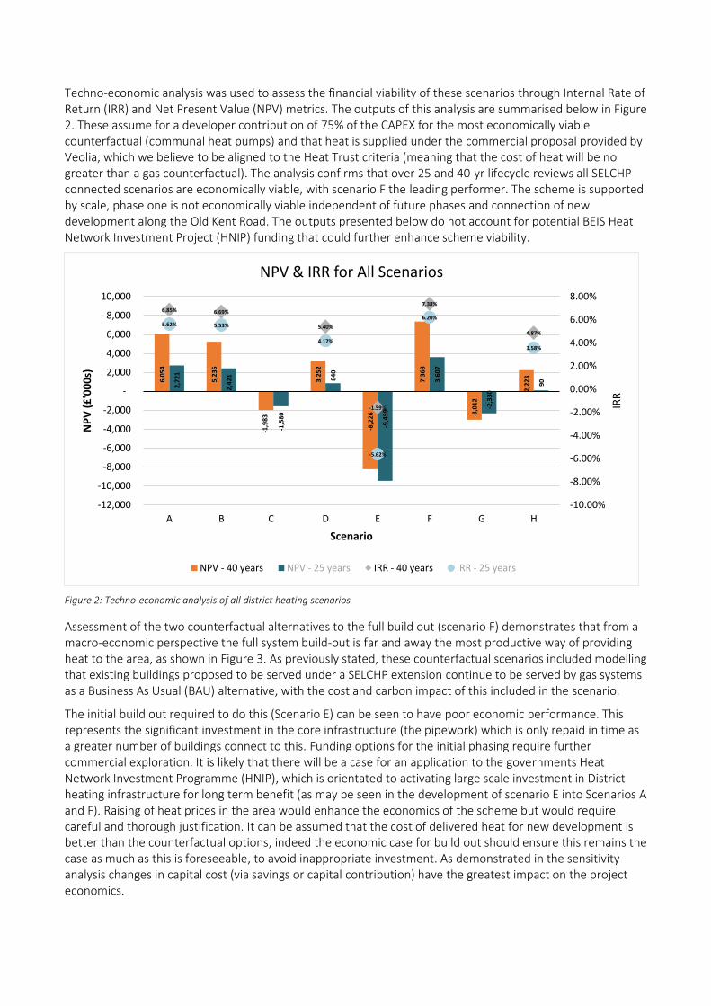
Techno-economic analysis was used to assess the financial viability of these scenarios through Internal Rate of Return (IRR) and Net Present Value (NPV) metrics. The outputs of this analysis are summarised below in Figure 2. These assume for a developer contribution of 75% of the CAPEX for the most economically viable counterfactual (communal heat pumps) and that heat is supplied under the commercial proposal provided by Veolia, which we believe to be aligned to the Heat Trust criteria (meaning that the cost of heat will be no greater than a gas counterfactual). The analysis confirms that over 25 and 40-yr lifecycle reviews all SELCHP connected scenarios are economically viable, with scenario F the leading performer. The scheme is supported by scale, phase one is not economically viable independent of future phases and connection of new development along the Old Kent Road. The outputs presented below do not account for potential BEIS Heat Network Investment Project (HNIP) funding that could further enhance scheme viability.
Figure 2: Techno-economic analysis of all district heating scenarios
Assessment of the two counterfactual alternatives to the full build out (scenario F) demonstrates that from a macro-economic perspective the full system build-out is far and away the most productive way of providing heat to the area, as shown in Figure 3. As previously stated, these counterfactual scenarios included modelling that existing buildings proposed to be served under a SELCHP extension continue to be served by gas systems as a Business As Usual (BAU) alternative, with the cost and carbon impact of this included in the scenario.
The initial build out required to do this (Scenario E) can be seen to have poor economic performance. This represents the significant investment in the core infrastructure (the pipework) which is only repaid in time as a greater number of buildings connect to this. Funding options for the initial phasing require further commercial exploration. It is likely that there will be a case for an application to the governments Heat Network Investment Programme (HNIP), which is orientated to activating large scale investment in District heating infrastructure for long term benefit (as may be seen in the development of scenario E into Scenarios A and F). Raising of heat prices in the area would enhance the economics of the scheme but would require careful and thorough justification. It can be assumed that the cost of delivered heat for new development is better than the counterfactual options, indeed the economic case for build out should ensure this remains the case as much as this is foreseeable, to avoid inappropriate investment. As demonstrated in the sensitivity analysis changes in capital cost (via savings or capital contribution) have the greatest impact on the project economics.
6,0
54
5,2
35
-1,9
83
3,2
52
-8,2
26
7,3
68
-3,0
12
2,2
23
2,7
21
2,4
21
-1,5
80
840
-9,4
59
3,6
07
-2,3
30
90
6.85% 6.69%
5.40%
-1.59%
7.38%
4.87%
5.62% 5.53%
4.17%
-5.62%
6.20%
3.58%
-10.00%
-8.00%
-6.00%
-4.00%
-2.00%
0.00%
2.00%
4.00%
6.00%
8.00%
A B C D E F G H
-12,000
-10,000
-8,000
-6,000
-4,000
-2,000
-
2,000
4,000
6,000
8,000
10,000
IRR
Scenario
NP
V (
£'0
00
s)
NPV & IRR for All Scenarios
NPV - 40 years NPV - 25 years IRR - 40 years IRR - 25 years

Balancing of the cost of capital from various sources (including potential HNIP funding), the final scope of the scheme and further focus on reducing the risk of construction and defining the capital cost of the project is likely to determine the final heat price for consumers, and is a key commercial consideration in the next stage of any potential project.
Figure 3: Net Present Value comparison – District heating full build-out vs. counterfactual scenarios
7,368
-78,286
-284,841
Full Build Out - SELCHP Communal Heat Pump Systems Individual Heat Pump Systems
-300,000
-250,000
-200,000
-150,000
-100,000
-50,000
-
50,000
Scenario
NP
V (
£'0
00
s)
NPV - Full build-out vs. Counterfactuals
Carbon footprint
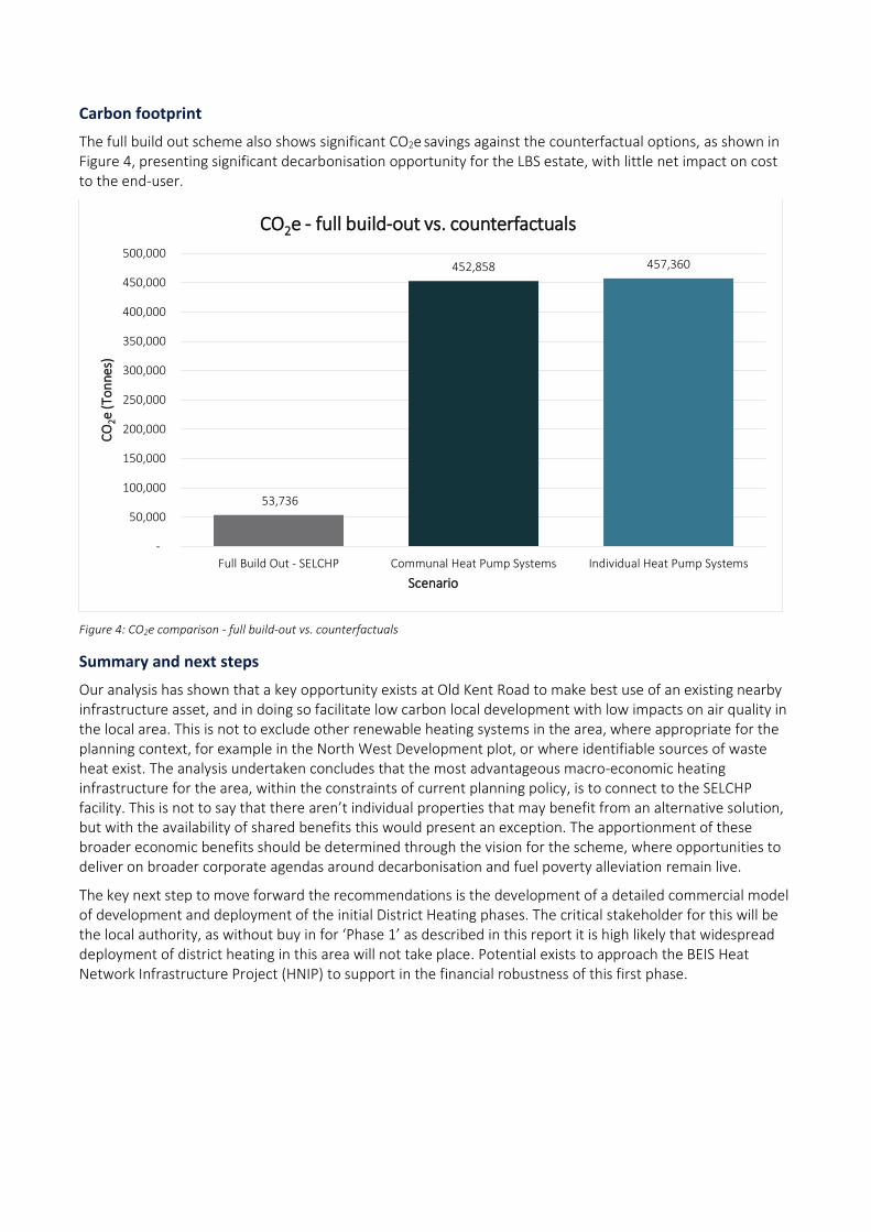
The full build out scheme also shows significant CO2e savings against the counterfactual options, as shown in Figure 4, presenting significant decarbonisation opportunity for the LBS estate, with little net impact on cost to the end-user.
Figure 4: CO2e comparison - full build-out vs. counterfactuals
Summary and next steps
Our analysis has shown that a key opportunity exists at Old Kent Road to make best use of an existing nearby infrastructure asset, and in doing so facilitate low carbon local development with low impacts on air quality in the local area. This is not to exclude other renewable heating systems in the area, where appropriate for the planning context, for example in the North West Development plot, or where identifiable sources of waste heat exist. The analysis undertaken concludes that the most advantageous macro-economic heating infrastructure for the area, within the constraints of current planning policy, is to connect to the SELCHP facility. This is not to say that there aren’t individual properties that may benefit from an alternative solution, but with the availability of shared benefits this would present an exception. The apportionment of these broader economic benefits should be determined through the vision for the scheme, where opportunities to deliver on broader corporate agendas around decarbonisation and fuel poverty alleviation remain live.
The key next step to move forward the recommendations is the development of a detailed commercial model of development and deployment of the initial District Heating phases. The critical stakeholder for this will be the local authority, as without buy in for ‘Phase 1’ as described in this report it is high likely that widespread deployment of district heating in this area will not take place. Potential exists to approach the BEIS Heat Network Infrastructure Project (HNIP) to support in the financial robustness of this first phase.
53,736
452,858 457,360
-
50,000
100,000
150,000
200,000
250,000
300,000
350,000
400,000
450,000
500,000
Full Build Out - SELCHP Communal Heat Pump Systems Individual Heat Pump Systems
CO
2e (
Ton
nes
)
Scenario
CO2e - full build-out vs. counterfactuals

Table of contents
Disclaimer ......................................................................................................................................................... 2
Anthesis Consulting Group ............................................................................................................................... 4
Executive summary .............................................................................................................................................. 5
Energy Masterplanning .................................................................................................................................... 5
Technology appraisal and energy centre locations .......................................................................................... 5
Network phasing and development schedule .................................................................................................. 5
Scenario development and the ‘counterfactual’ .............................................................................................. 6
Carbon footprint ............................................................................................................................................ 10
Summary and next steps ................................................................................................................................ 10
Table of contents ............................................................................................................................................... 11
Table of figures .................................................................................................................................................. 13
1 Introduction ........................................................................................................................................... 15
2 Scope of works ....................................................................................................................................... 16
3 Review of Energy Masterplan ................................................................................................................ 17
3.1 Peer review of previous work ............................................................................................................ 17
4 Planning Review and feedback .............................................................................................................. 20
4.1 Design approaches to address policy ................................................................................................. 21
5 Stakeholder engagement ....................................................................................................................... 24
5.1 Background ........................................................................................................................................ 24
5.2 Phase one: Initial Engagement ........................................................................................................... 25
5.3 Phase two: Focussed cluster engagement ......................................................................................... 26
5.4 Stakeholder roles and ongoing communications ............................................................................... 27
5.5 Data collection and review................................................................................................................. 27
6 Data Collection and Validation ............................................................................................................... 28
7 Energy mapping ..................................................................................................................................... 30
7.1 Heat Demand Mapping ...................................................................................................................... 30
7.2 Electrical demand mapping ............................................................................................................... 34
8 Low Zero Carbon technology review ..................................................................................................... 35
8.1 Introduction ....................................................................................................................................... 35
8.2 Gas-fired Combined Heat & Power (CHP) .......................................................................................... 35
8.3 Biomass .............................................................................................................................................. 36
8.4 Heat pumps ........................................................................................................................................ 36
8.5 Secondary Source Heat pumps .......................................................................................................... 42
8.6 Underground Bakerloo Line extensions ............................................................................................. 42
8.7 Electrical sub-stations ........................................................................................................................ 45

8.8 Other secondary heat sources ........................................................................................................... 46
8.9 Fuel Cell CHP ...................................................................................................................................... 47
8.10 Connection to SELCHP ....................................................................................................................... 48
8.11 Summary of heat generation technologies ........................................................................................ 51
9 Energy Centre Location Assessment ...................................................................................................... 53
9.1 Implications of the use of Heat pumps on Energy Centres ................................................................ 53
9.2 CHP Energy Centres within the Old Kent Road Development area .................................................... 54
9.3 Additional Energy Centres supporting a SELCHP District Heating system .......................................... 55
9.4 Energy Interface within development blocks ..................................................................................... 56
10 Production Modelling ............................................................................................................................ 59
10.1 District Heating, supplied by SELCHP ................................................................................................. 59
10.2 Counterfactuals to District heating .................................................................................................... 66
11 Hydraulic modelling ............................................................................................................................... 67
12 Energy Distribution ................................................................................................................................ 70
12.1 SELCHP and national rail infrastructure ............................................................................................. 70
12.2 Existing Utility Infrastructure ............................................................................................................. 70
12.3 Contaminated land ............................................................................................................................ 70
12.4 Old Kent Road .................................................................................................................................... 71
12.5 Phased installation ............................................................................................................................. 71
12.6 Electrical distribution ......................................................................................................................... 71
13 Energy Centre Concept Design .............................................................................................................. 73
13.1 SELCHP ............................................................................................................................................... 73
13.2 Thermal storage ................................................................................................................................. 75
13.3 Communal Heat pumps ..................................................................................................................... 76
13.4 Individual Heat Pumps ....................................................................................................................... 77
13.5 CHP based District Heating ................................................................................................................ 77
14 Techno-economic modelling .................................................................................................................. 79
14.1 Model structure and core assumptions ............................................................................................. 79
14.2 Capital Expenditure (CAPEX) .............................................................................................................. 80
14.3 Operational Expenditure (OPEX) ........................................................................................................ 82
14.4 Revenues and Income ........................................................................................................................ 85
14.5 Replacement Expenditure (REPEX) .................................................................................................... 86
14.6 Summary results ................................................................................................................................ 86
14.7 Carbon Dioxide emissions .................................................................................................................. 88
14.8 NOx ..................................................................................................................................................... 92
14.9 Refrigerants ....................................................................................................................................... 92

15 Sensitivity and Risk ................................................................................................................................. 93
16 Implementation plan and QA ................................................................................................................. 98
17 Application for funding ........................................................................................................................ 100
18 Recommendations and next steps ....................................................................................................... 102
18.1 Connection to SELCHP ..................................................................................................................... 102
18.2 Other Practicalities ........................................................................................................................... 103
18.3 Other Solutions ................................................................................................................................ 103
18.4 Heat Network Investment Project application ................................................................................. 104
18.5 Final Conclusions and next steps ..................................................................................................... 104
Table of figures
Figure 1: Development areas, with proposed Phase 1 and Phase 2 network build outs, and potential full build out network routing ............................................................................................................................................................................. 6
Figure 2: Techno-economic analysis of all district heating scenarios ......................................................................................... 8
Figure 3: Net Present Value comparison – District heating full build-out vs. counterfactual scenarios .................................. 9
Figure 4: CO2e comparison - full build-out vs. counterfactuals ................................................................................................ 10
Figure 5: Showing plots and opportunity area boundaries from the AECOM masterplan ...................................................... 17
Figure 6: Plot heat demands and network routes from AECOM feasibility study ................................................................... 18
Figure 7: London Heat Map – LB Southwark .............................................................................................................................. 21
Figure 8: Stakeholder influence / commitment matrix for the Old Kent Road, London Borough of Southwark ................... 26
Figure 9. GIS plot of the Old Kent Road Development area (dotted line), showing developments with differing sizings, build ups and phasing .................................................................................................................................................................. 29
Figure 10: Initial Heat Cartograph of Old Kent Road – please see Appendix D for full output ............................................... 30
Figure 11: Zoning for Linear Heat Density Analysis ................................................................................................................... 31
Figure 12: Local Authority sites surveyed as potential anchor loads and alternative energy centre locations in and around the Old Kent Road Development Area ....................................................................................................................................... 32
Figure 13: Initial Electrical demand Cartograph of the Old Kent Road Area – Please see Appendix C for full output .......... 34
Figure 14: User interface from BGS Geology of Britain viewer ................................................................................................. 37
Figure 15: Example borehole log ................................................................................................................................................ 38
Figure 16: Excerpt from desktop contaminated land review of development area for routing by 3DTD – please see Appendix E for more information ............................................................................................................................................... 41
Figure 17: Potential London underground station boxes within the development area (TfL) ................................................ 42
Figure 18: Location of major electrical sub-stations within the Old Kent Road Development area ....................................... 45
Figure 19: The SELCHP facility ..................................................................................................................................................... 48
Figure 20: Major Sub-station and proposed energy centres .................................................................................................... 54
Figure 21: Typical Twin Plate Thermal Sub-station equipment schematic............................................................................... 56
Figure 22: Revised Old Kent Road Development area phasing – divided into plots ................................................................ 59
Figure 23: Proposed District Heating Network Phasing approach in Old Kent Road Area ...................................................... 60

Figure 24 a,b,c: Various potential phased district heating build outs across the North, West and South Old Kent Road development plots, In reaction to staged build out of developments in this location ............................................................ 62
Figure 25: Potential stand-alone district heating network in North West Plot of the Old Kent Road Development area .... 63
Figure 26: Potential full network build out after Phase 1 and Phase 2, including Northwest link .......................................... 64
Figure 27: Excerpt from Initial Hydraulic model calculation, detailing estimated pipe sizing ................................................. 68
Figure 28: Modelled heat demand curve for Phase 1 of the Old Kent Road District Heating development ......................... 74
Figure 29: Typical Communal Air Source Heat Pump plant room space requirements .......................................................... 76
Figure 30: Example typical Individual Air Source Heat Pump with Packaged Thermal Store .................................................. 77
Figure 31: Typical CHP Energy Centre/ Plant room requirements............................................................................................ 78
Figure 32: A breakdown of the CapEx for each of the scenarios modelled. ............................................................................ 81
Figure 33: NPV & IRR results over 25 and 40 years for all scenarios ........................................................................................ 86
Figure 34: NPV comparison between the district heating network build out and counterfactuals ....................................... 87
Figure 35: A comparison of 40 year whole life Carbon Dioxide emissions for various district heating build out scenarios . 88
Figure 36: A comparison of 40 year whole life carbon emissions between a district heating solution, and the heat pump and gas boiler counterfactuals .................................................................................................................................................... 90
Figure 37: An investigation of district heating model sensitivity against various parameters ................................................ 94
Figure 38: A comparison of impacts of key assumptions on the outputs of the techno economic model ............................ 96
Figure 39 – Areas with Potential Opportunities for District Heating Schemes ......................................................................119

15
1 Introduction
The Old Kent Road is a historic part of South East London, forming the principal urban route to Dover and the wider Kent area since before Roman times. The road is within a few miles of central London and currently lined with a range of business and retail parks, as well as residential areas. Public transport in the area is dominated by the public bus network, however proposals exist to extend the Bakerloo Line beneath the road up to Lewisham and potentially the wider South East London Area. This combined with several existing retail and business sites meeting the end of their economic cycle and becoming available to development has the potential to act as a catalyst for change in this part of London. In four key areas adjacent to the Old Kent Road there is opportunity for extensive redevelopment and expansion of residential, commercial and other supporting facilities within the borough. The area has an industrial heritage, and as a result, several key energy infrastructure facilities exist locally. These include:
• A historic gas works – which forms the centre of distribution for the modern gas infrastructure
• A Grid supply point – (connection to the national grid) also forming part of the electrical supply to the surrounding rail infrastructure
• The SELCHP Energy from Waste facility, which manages residual waste from the local boroughs, producing electricity and some heating in the regional area.
The area has been assessed to have the potential to house approximately 10,000 additional residencies, with a further 10,000 residencies facilitated by improvements to public transport infrastructure, envisaged to be in the main part an extension of the Bakerloo Line. The energy demands of this volume of housing require strategic planning by the local authority to assess the most suitable manner these can be supplied by, and to mitigate the potential impacts on:
• Whole Life cost
• Infrastructure installation and expansion
• Local environment from both a Carbon emission, and Air Quality perspective
National, regional and local policies in the UK are promoting that these needs are met with increasingly local or ‘Decentralised’ sources. A common example has been the rise of rooftop Solar Photovoltaic systems that has been observed around London. Anthesis Energy UK have been commissioned by the London Borough of Southwark to review the energy demands of the estimated development in this region and propose strategic solutions to supply these, whilst mitigating the environmental impact (where feasible) and minimising the whole life cost to existing and future residents in the borough. The findings of this analysis are presented in the following report.
16
2 Scope of works
Anthesis were originally appointed in May 2018 to provide a Decentralised Energy Feasibility Study for the Old Kent Road Development area. The scope of works included:
• Reviewing previous works conducted in past consultations
• Reviewing the prevailing planning policies and framework
• Mapping development across the study area
• Estimating thermal and electrical loads across the proposed development area
• Review renewable energy supply opportunities, including opportunities to utilise waste heat available in the area
• Determine a viable strategy or strategies to supply energy demands
• Undertake an initial design for any system or systems. Specifically, where decentralised heating systems and district heating were to be investigated, propose routings, with energy centre locations
• Estimate capital costs for systems proposed
• Undertake Operations modelling and construct a techno-economic model for the proposed system or systems to determine the whole life cost of various strategies
• Estimate carbon emissions arising from the proposed strategies
• Provide a commentary on the Air Quality impacts (NOx emissions) for the proposed Strategies
• Provide a recommendation of which strategies to pursue and the reasoning behind this
Together with our partners, 3DTD we have also:
• Outlined in detail potential routing of a heat network through the borough and development area
• Provided an initial risk assessment for routing and foreseeable hazards that may impact the route
• Focused on providing a greater detail on the capital elements of the pipe network for the cost modelling, owing to the risk inherent in this type of civil engineering.
After our initial investigations we recommended an extension of the scope at the close of 2018, to encompass a review of other local authority decentralised energy opportunities in the area. Specifically, providing a greater level of detail on potential local authority loads in and around the development, which may also support a decentralised energy strategy. This included:
• Working with the local authority and partners to identify likely large local authority heating demands
• Reviewing existing data (where available) from these properties to assess annual load profiles
• Additional site surveys and visits to facilities to ascertain condition and connection opportunities for decentralised systems. This included 10 residential sites and 8 Education facilities
• Revisiting and re-planning network routing to make use of any opportunities where they exist
This exercise was completed by Q2 2019, allowing the compilation of results. At this stage a revised phasing of development became apparent and loading and phased deployment of the strategy was extensively revisited. This led to changes to anticipated loads, hydraulic arrangement, the phased roll out strategy, which have been incorporated into this study and report. Anthesis’s conclusions are presented in the following sections.

17
3 Review of Energy Masterplan
This feasibility study builds on a masterplanning study carried out by AECOM in 2016. The geographical scope of the study area encompasses three sub-areas. These areas are illustrated in Figure 5 below:
Sub area 1: comprising the following site allocations: • OKR2 : Crimscott Street and Pages Walk • OKR3: Mandela Way • OKR4: Durton Road and Southernwood Retail Park Sub area 2: comprising the following site allocations: • OKR10: Land bounded by Glengall Road, Latona Road and Old Kent Road
Sub area 3: comprising the following site allocations: • OKR 11: Marlborough Grove and St James’s Road • OKR 13: Sandgate Street and Verney Road • OKR 16: Hatcham road and Ilderton Road • OKR 18: Devon Street and Sylvan Grove
3.1 Peer review of previous work
A masterplanning report was undertaken by AECOM in June 2016 for the Old Kent Road Opportunity Area.
Heat demands were calculated based on development information from Southwark Council’s place-marking study, with plots as illustrated below in Figure 5:
Figure 5: Showing plots and opportunity area boundaries from the AECOM masterplan

18
The study considered a range of heat generation technologies – gas-fired CHP, fuel cell CHP, biomass boilers, biomass CHP, heat pumps (linked to secondary heat sources) and energy from waste. Of these, gas fired CHP and waste heat from SELCHP were recommended as a first wave of heat supply technology, with heat pumps recommended for future consideration.
Anthesis is broadly in agreement with these findings (4 Planning Review and feedback) and would further note that, with the development of the plans for the extension of the Bakerloo line along Old Kent Road, additional heat extraction from ground or air-source could add to viability.
The study resulted in three network options:
• Option 1: a phased heat network with a single energy centre located within the opportunity area, housing a gas-fired CHP.
• Option 2: a variant of option 1, comprising three smaller interconnected energy centres • Option 3: a variant of Option 1 with a connection to SELCHP to supply part of the heat
demand. The sites and proposed network routes are illustrated in Figure 6 below:
Figure 6: Plot heat demands and network routes from AECOM feasibility study
The network build-out is considered on a phased basis, being extended as new development is completed. Build phases are grouped according to the following: 2015-2025 (Phase 1), 2025-2030 (Phase 2) and 2030-2036 (Phase 3).

19
3.1.1 The AECOM methodology
Heat demands modelled were extracted from the London Heat Map, with data from a local employment study carried out by Southwark Council, the Local Land and Property Gazetteer, and data provided by Southwark Council on existing housing estates used to identify existing demands. For new / potential future development, benchmarking based on AECOM’s experience of dynamic simulation modelling and SAP / IES modelling was employed.
Three development scenarios were modelled, and the high development scenario selected as the preferred option on which to base the energy options analysis. We would question this approach, as there is a risk of equipment being oversized and subsequently failing to perform in line with modelling.
The modelling recommends the development of three smaller, interconnected energy centres as both the most financially attractive and realistic manner of building out the heat network, although it is noted that there are potential challenges in terms of space take inherent in a larger number of energy centres.
Although it is noted that the project is viable, there are also several inherent risks in this approach. It is these that we aim to address further in the following report. These include (but are not limited to):
• The changing policy context, including the continuing evolution of carbon factors
• The increased cost of 3 separate systems versus one larger system benefiting from economics of scale
• An increased likelihood one or more of the schemes would not proceed
• The hydraulic complexity of 3 interlinked, and potentially separately run networks and energy centres.
20
4 Planning Review and feedback
The policy review is documented within Appendix A1, with this section serving to discuss the main findings and the implications on the project.
The following planning policy and supporting documentation is reviewed within this appendix:
• Building Regulations 2013, including SAP
• London Sustainable Design and Construction: Supplementary Planning Guidance (SPG), published April 2014
• Greater London Authority guidance on preparing energy assessments, published March 2016
• London Plan, March 2016
• Draft London Plan, December 2017
• London Environment strategy, May 2018
• London Borough of Southwark planning policy, namely:
o Southwark Core Strategy (2011)
o New Southwark Plan (in consultation)
o Energy and Carbon Reduction Strategy (2011)
o Sustainable Design and Construction SDP (2009)
o Old Kent Road Area Action Plan (2017)
AECOM’s Old Kent Road Decentralised Energy Strategy was published after many regional and local policy documents (by the Greater London Authority (GLA) / Southwark Council respectively) were formally adopted. As such, most of the policy analysis and findings from that document remain valid.
It is understood that the assumptions and proposals made in the AECOM report as part of the network optioneering were valid against the policy requirements in place at the time of publication.
Subsequently published after the AECOM report are the GLA Environmental Strategy and the newly proposed London Plan (expected to be adopted in the Winter 2019). These new documents go beyond the policy requirements prevalent in 2016 predominantly in the area of Air Quality, with London aiming to “have the best air quality of any major world city by 2050”. They also recognise that previous policy has focussed on carbon reduction and air quality in isolation and seek to now address these concurrently.
The GLA produces a ‘heat map’ of London which estimates heat demand density across London, records the locations of existing Decentralised Energy Networks, development opportunity areas and sites where it is considered there is potential for new networks, including estimating where District Heating Opportunities exist and the extent of these across the city. The heat map is used by the GLA and local authorities to help determine which energy policy applies to a given development.
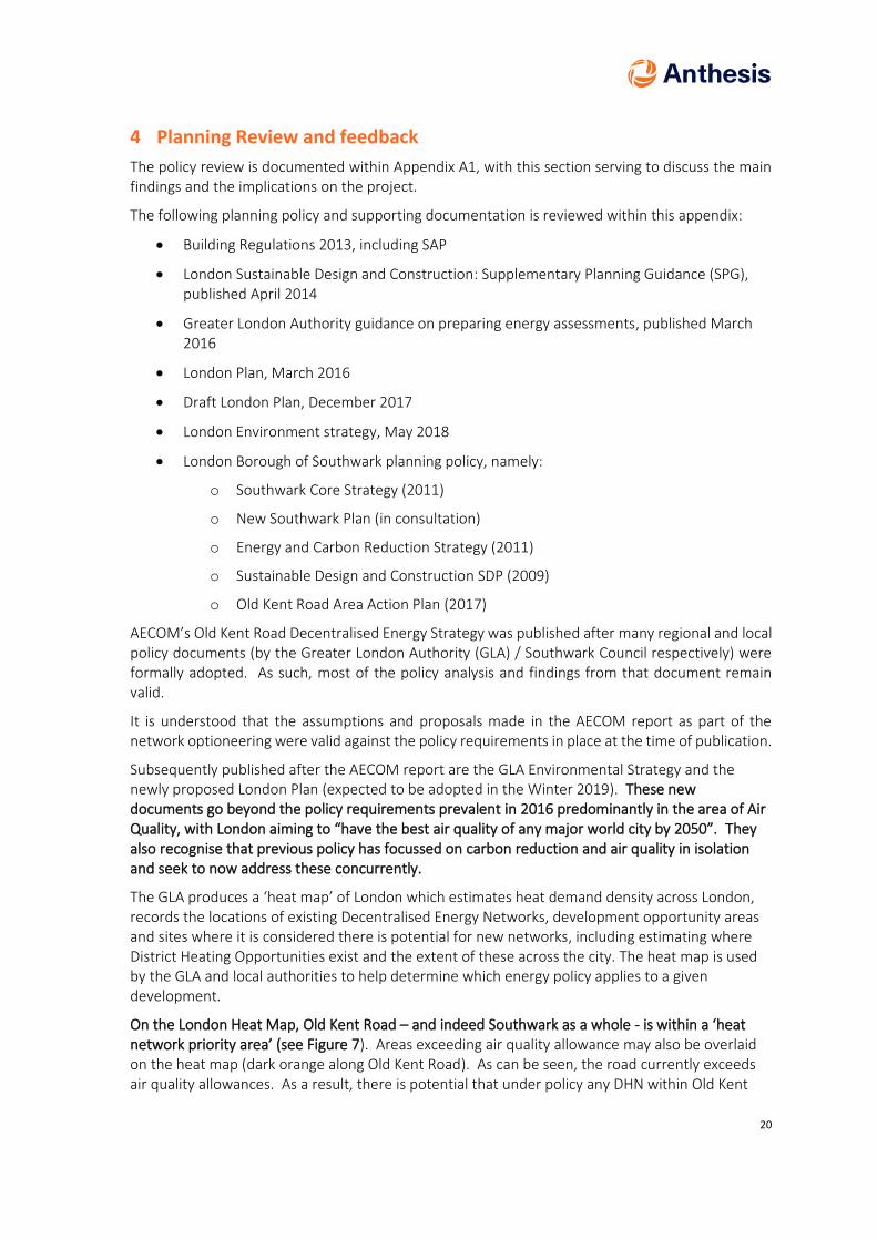
On the London Heat Map, Old Kent Road – and indeed Southwark as a whole - is within a ‘heat network priority area’ (see Figure 7). Areas exceeding air quality allowance may also be overlaid on the heat map (dark orange along Old Kent Road). As can be seen, the road currently exceeds air quality allowances. As a result, there is potential that under policy any DHN within Old Kent

21
Road will be required both to install a heat network with an increased focus on NOx emissions arising from this. The response to any NOx emissions target set by the planning authority is likely to have a substantive impact on the selection of low carbon heat sources for the network, and potentially the technical parameters (e.g. temperatures) of the heat network.
Figure 7: London Heat Map – LB Southwark
4.1 Design approaches to address policy
Energy policy related to construction continues to evolve and develop to align with wider policy goals such as the Paris Agreement and the legal aspirations of the Government to reduce carbon by 80% by 2050. The draft London Plan is also proposing to link reductions in carbon emissions with improvements in air quality.
The construction industry has geared up to address the requirements of energy efficient construction leading to much more experience in constructing well insulated airtight buildings, often with greater levels of mechanical and electrical equipment and building service complexity. Several physical constraints and policy drivers are now impacting the next step in policy change. Broadly speaking, these are in new build construction:
• Decreasing returns from increased levels of insulation and airtightness. Solid fabric is regularly achieving U values below 0.15 W/m2K, high performance double glazing or facades are the norm and air tightness of <3 m3h-1m-2 @ 50 Pa is also regularly targeted.
• Decreasing returns from energy efficient ventilation, as various forms of Mechanical Ventilation with Heat Recovery (MVHR) systems are now regularly used.
• Better Fabric and ventilation systems are resulting in low levels of space heating demand, with overheating and in commercial buildings, cooling becoming a greater challenge.
• Decreasing consumption of water, and with this Domestic Hot water, as this has fallen under building regulations, leading to reduced DHW demand.
As a result, further reductions in energy demand are becoming harder to achieve and are unlikely to have significant further impacts on carbon reduction. This drives an increased focus in policy on Low/zero carbon energy supply. The draft London Plan and supporting documentation are seeking to promote:

22
• A policy requirement for the residual space and DHW heating to be met from low/zero carbon systems.
• A policy requirement for networked heating systems (wet communal and district heating) to allow for interconnection and the integration of low carbon heating systems.
• A policy requirement for ‘Air Quality positive’ developments, linking NOx emissions from combustion (heating) plant on new build to wider urban air quality targets. This potentially penalises three combustion based low carbon solutions (Biomass, gas-CHP, gas fired heat pumps) and the widely used gas boiler.
In the same timeframe, falls in electrical carbon emissions for base load production are reducing UK national average annual electricity carbon factors. This makes electrical heat sources appear an attractive technical heating solution and is reducing the number of hours where CHP may contribute to reducing carbon emissions. The same factor is affecting UK wholesale electrical prices and therefore also CHP sizing approaches, favouring larger engines operating shorter hours but with greater thermal storage.
The risk of focusing on the annual average electrical factor is a lack of appreciation of the distribution of the diverse electrical generation sources against time. The average annual factor is likely to understate the impact of emissions during the winter and at peak load (cold weather periods) and does not also consider other practical limitations, such as local, regional and national UK electrical infrastructure limitations for supplying peak loads.
These emerging, divergent objectives are creating numerous challenges for designers to address:
• As highlighted, there is reduced scope for the cost-effective reduction of carbon emissions from improvements to fabric and ventilation systems. This is reflected in the limitations the new London Plan and BREEAM have on requiring further reductions beyond building regulations from these measures.
• Conventional wet heating systems operating at temperatures >60oC, and reliant on combustion heat sources (Biomass, CHP, gas fired Heat Pumps, gas boilers) are likely to increasingly conflict with air quality drivers.
• Nascent wet heating systems utilising very low temperature distribution (<60oC) or ambient loop networks and heat pumps appear more favourable but are less well understood resulting in higher construction risk. The lower operating temperatures are required for the efficient operation of this heat producing equipment. There are also potential conflicts within these solutions associated with UK legionnaire’s disease regulation.
• There is some difficulty in ‘standardising’ less traditional system operating temperatures and their integration to allow wider wet heating networks.
• The selection of electric heat pumps for heating will be placing a greater reliance on the local electrical grid infrastructure and future decarbonisation of electricity, particularly peak electricity supplies.
• Difficulties in space planning and layout. Traditional gas fired plant favours basement level plant space, however less traditional large electrical Air Source Heat Pump systems favour roof level plant space. Confirming required plant areas without compromising future heating source flexibility is likely to be a challenge.

23
The draft London Plan, LB Southwark policy and other government drivers promote the installation of a wider DHN in the study area. Heat networks do offer the ability of interconnection of thermal loads, diversifying demand across numerous built forms, construction types and occupations. They also ease the integration of low / zero carbon (LZC) plant and with the scaling up of these, help increase the energy efficiency of production, centralise the treatment of any combustion gases and potentially lower operational costs. They are particularly effective at lowering the carbon emissions of the harder to treat existing built environment.

24
5 Stakeholder engagement
5.1 Background
Recognising that early stakeholder engagement is critical to the success of heat networks, we looked to implement and evolve a stakeholder strategy throughout the course of the project.
We followed the BEIS Stakeholder Engagement in Heat Networks methodology to develop our overarching strategy for feasibility. In line with standard PRINCE2 protocol, the process is delivered over five steps as follows:
• Stakeholder identification
• Stakeholder mapping
• Stakeholder prioritisation
• Planning
• Engagement
The timelines for project delivery and governance necessitated this approach to be modified somewhat. As such we split the engagement process into two phases; firstly, raising awareness of the project and secondly, more direct engagement.
• Phase one: At project outset. Initial engagement and data collection
• Phase two: On completion of cluster identification. Focussed engagement based on viable scheme options
25
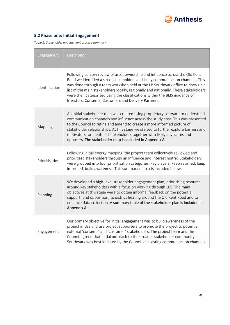
5.2 Phase one: Initial Engagement
Table 2: Stakeholder engagement process summary
Engagement Description
Identification
Following cursory review of asset ownership and influence across the Old Kent Road we identified a set of stakeholders and likely communication channels. This was done through a team workshop held at the LB Southwark office to draw up a list of the main stakeholders locally, regionally and nationally. These stakeholders were then categorised using the classifications within the BEIS guidance of Investors, Consents, Customers and Delivery Partners.
Mapping
An initial stakeholder map was created using proprietary software to understand communication channels and influence across the study area. This was presented to the Council to refine and amend to create a more informed picture of stakeholder relationships. At this stage we started to further explore barriers and motivators for identified stakeholders together with likely advocates and opposers. The stakeholder map is included in Appendix A.
Prioritisation
Following initial energy mapping, the project team collectively reviewed and prioritised stakeholders through an Influence and Interest matrix. Stakeholders were grouped into four prioritisation categories: key players, keep satisfied, keep informed, build awareness. This summary matrix is included below.
Planning
We developed a high-level stakeholder engagement plan, prioritising resource around key stakeholders with a focus on working through LBS. The main objectives at this stage were to obtain informal feedback on the potential support (and opposition) to district heating around the Old Kent Road and to enhance data collection. A summary table of the stakeholder plan is included in Appendix A.
Engagement
Our primary objective for initial engagement was to build awareness of the project in LBS and use project supporters to promote the project to potential external ‘consents’ and ‘customer’ stakeholders. The project team and the Council agreed that initial outreach to the broader stakeholder community in Southwark was best initiated by the Council via existing communication channels.

26
Figure 8: Stakeholder influence / commitment matrix for the Old Kent Road, London Borough of Southwark
5.3 Phase two: Focussed cluster engagement
The second phase of stakeholder engagement was focused within the proposed clusters identified following completion of the energy masterplan review. The intention here is to focus on the stakeholders unique to each cluster and those that have a role across all. Reference is made across stakeholders and projects within the stakeholder plan included in Appendix A. Stakeholder responses were positive and the Council resource to drive this process worked effectively. Stakeholder engagement remains a risk in any future development phases, though a process has now been developed to mitigate and manage this risk. We are particularly interested in the role of Veolia in extending the SELCHP scheme and LBS in providing the anchor loads to underpin development. Engagement with developers came late in the process but was felt to be generally positive subject to confirmation of the deliverability of the scheme and policy positions on carbon offset payments.

27
5.4 Stakeholder roles and ongoing communications
Investors: At present five potential broad stakeholders exist in this space; the Council, developers, Veolia, BEIS and external delivery partners. We have established the conditions for investment with both LBS and Veolia. The conditions for investment from developers that may wish to take a more active role in scheme development are still to be determined. The outline design and economics for a range of design scenarios have now been established and can be presented to stakeholders for further feedback before undertaking more detailed analysis.
Consents: Initial engagement with planning, highways and facilities within the Council has been progressed. We have consulted with the planning and highways team in the determination of network routes and energy centre locations. We have also reviewed the Utility Infrastructure assessment, which we understand is obtained from UKPN to determine potential infrastructure capacity constraints. Broader local influencers such as local media and resident groups have not yet been engaged.
Customers: We have reached out to the customers and developers identified within the proposed clusters. Engagement has been positive and there has been provision of useful data to build confidence in study conclusions. We undertook site visits across the study area and contacted key Council staff to determine connection viability and energy centre design within the City Centre scheme. The Council and other public / third sector partners have several buildings within this area that materially affect scheme viability.
Delivery Partners: Delivery partners are difficult to identify at this stage. Anthesis have been in dialogue with the market to verify proposed costings, risks and technical assumptions.
5.5 Data collection and review
As part of the data collection process the team set out a process to maximise the receipt of actual energy consumption data. In terms of granularity and accuracy, data quality can be categorised as: half-hourly; monthly; annually; estimated; and benchmarked. Response rates have been good, but the data sets are variable in quality, leading to extensive synthesised profiling throughout.
In addition, the team captured other important energy infrastructure information through dialogue with the Council, Western Power Distribution and the Environment Agency.
The project team employed a best practice approach to data collection which included:
• Utilising existing communication channels and relationships to improve response rates;
• Where possible, minimising the burden of data collection on external parties;
• Using telecoms communication ahead of e-mail; and
• Maintaining a stakeholder engagement log.

28
6 Data Collection and Validation
The nature of the Old Kent Road Opportunity area, in that it is in the early stages of planning, means that little exact data on the nature of future development is available. Information that is currently available comes from the following broad range of sources:
1. Current planning submissions – i.e. submissions made to the Local Authority for permission to build in the immediate future
2. Local authority planning projections – i.e. estimations from the local authority as to the capacity of the local area for future development considering environmental and infrastructure restrictions – for example, restrictions on public transport
3. Site visits and walkarounds – to assess the current status of the development area.
In the course of the engagements the scope of the study was further extended to include some surrounding local authority owned areas. These were:
1. Local authority social housing developments 2. A selection of Local authority schools and academies
Anthesis conducted detailed condition surveys of these facilities (see Appendix C) on behalf of the local authority, as well as energy analysis (degree day) from billing and spot meter readings.
Broadly speaking, new build areas were assessed from the local authority and planning data, whilst existing consumption was assessed from on-site surveys and billing data.
Satellite photography and GIS software was used to plot proposed and current developments around the opportunity area (Figure 9). Loads were estimated using a range of techniques.
Commercial areas make up a smaller area of development in comparison to the proposed residential loads. For new build commercial areas the declared loads in recent planning submissions were assessed on a scatter plot on a kWh/m2 basis for different planning types. The median loads were selected as a future projection of later submissions. The magnitude of these, as well as the theoretical balance point of these spaces were testing using a generic CIBSE TM41 degree-day model. The two basic components, a heating load per m2 area of commercial development (divided into planning categories, A1, A2 B1 etc) and balance point temperature (from TM41 model) provide the basis of the load modelling for these areas.
New build residential load, which makes up a large proportion of the planned development was assessed using a building regulation SAP methodology. This is in its nature, also a degree-day-based space heating assessment. Again, a review was undertaken of planning submissions, with typical current building fabric parameters proposed graphed on a scatter plot. The median fabric parameters from the submissions were used to predict likely future submission fabric parameters, and representative SAP calculations undertaken with these to estimate likely residential heating loads, on a m2 of residential area basis. A TM41 model was used to estimate the balance point for the new residencies.

29
Figure 9. GIS plot of the Old Kent Road Development area (dotted line), showing developments with differing sizings, build ups and phasing
The build out typology of future unknown development was estimated using the GLA planning guidelines for minimum floor area and quantum of differing residential types (e.g. Studio, 1 bed, 2 bed, 3 bed property etc). Domestic Hot Water load (DHW) was assessed from this build out typology using the SAP methodology.
A schedule of the proposed and potential development across the Old Kent Road area, matched to these load estimations formed the basis of the projected new build heating demand.
Where existing buildings form part of the proposed energy solution real billing data was used to assess current energy consumption. In some locations, estimates were required, and these were based on consumption of similar nearby sites. Degree day analysis was used to split out the dependent (assumed space heating) load from the base (non—dependent) load. A further estimation of DHW consumption per property allowed the non-dependent load to be broken into an estimate of DHW energy consumption and existing system losses.

30
7 Energy mapping
7.1 Heat Demand Mapping
The outputs from the energy demand modelling outlined in the section above were modelled in GIS and can be seen in Figure 10 below.
For each load, a circle was plotted in proportion to its heat demand, producing a cartogram of heat demand.
Figure 10: Initial Heat Cartograph of Old Kent Road – please see Appendix D for full output
From an early stage – considering the location of these loads and the relative location of the nearby waste heat source (SELCHP) it was clear that a piece of key energy distribution infrastructure – the main supply pipe for a district heating system would be required to be installed to the Old Kent Road redevelopment area in order to facilitate this technological option. This faces several other local infrastructure challenges, particularly crossing nearby local heavy rail infrastructure, likely to increase the complexity of installation and cost.
As an initial test of viability of district heating infrastructure considering these constraints, linear heat density analysis was conducted of the estimated quantum of heat available across the Old Kent Road. Linear heat density assesses the proximity (m) and scale of heat demand (MWh) to understand whether these should be networked or treated independently. The analysis looks to understand the benefits of whole system thinking across multiple plots and existing buildings to understand a strategy for linking these together (or not).
The development area was divided into four ‘plots’ described as following on the points of the compass in relation to the Old Kent and New Rotherhithe roads.

31
• Northwest – a standalone plot at the top of the Old Kent Road separated from the main body of development
• North – a small sub-plot of the main development divided by the Rotherhithe New Road
• West- the part of the main development across the Old Kent Road
• South – The major part of the development area between the railways, the Old Kent Road and the New Rotherhithe Road
Figure 11: Zoning for Linear Heat Density Analysis
An initial network route was plotted into these areas, as illustrated in Figure 11 above. Please note this does not yet account for phasing, which has driven some routing changes in comparison to the above layout. The linear heat density for each plot was estimated by dividing heat loads by the length of the initial network route. Note this analysis considers just the pipework with a plot, therefore the network length to SELCHP is excluded. The results are as follows in Table 3.
Table 3: Linear Heat Density of Old Kent Road Development Plots
Cluster Liner Heat Density (MWh/m)
North 4.9
West 4.8
Northwest 8.0
South 4.4
32
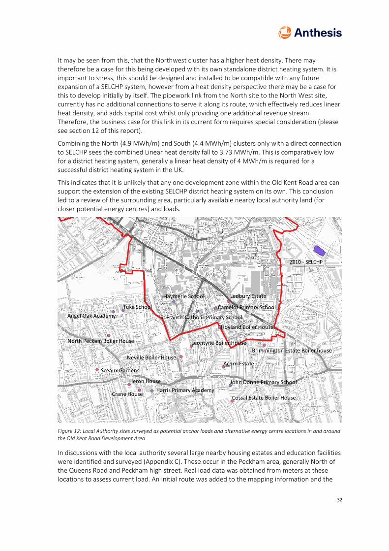
It may be seen from this, that the Northwest cluster has a higher heat density. There may therefore be a case for this being developed with its own standalone district heating system. It is important to stress, this should be designed and installed to be compatible with any future expansion of a SELCHP system, however from a heat density perspective there may be a case for this to develop initially by itself. The pipework link from the North site to the North West site, currently has no additional connections to serve it along its route, which effectively reduces linear heat density, and adds capital cost whilst only providing one additional revenue stream. Therefore, the business case for this link in its current form requires special consideration (please see section 12 of this report).
Combining the North (4.9 MWh/m) and South (4.4 MWh/m) clusters only with a direct connection to SELCHP sees the combined Linear heat density fall to 3.73 MWh/m. This is comparatively low for a district heating system, generally a linear heat density of 4 MWh/m is required for a successful district heating system in the UK.
This indicates that it is unlikely that any one development zone within the Old Kent Road area can support the extension of the existing SELCHP district heating system on its own. This conclusion led to a review of the surrounding area, particularly available nearby local authority land (for closer potential energy centres) and loads.
Figure 12: Local Authority sites surveyed as potential anchor loads and alternative energy centre locations in and around the Old Kent Road Development Area
In discussions with the local authority several large nearby housing estates and education facilities were identified and surveyed (Appendix C). These occur in the Peckham area, generally North of the Queens Road and Peckham high street. Real load data was obtained from meters at these locations to assess current load. An initial route was added to the mapping information and the

33
additional loads to the load schedule. A revision of the Linear heat analysis indicates that the linear heat density of the resulting system rises to 4.92 MWh/m. This is more likely to be a viable system, with the existing loads supporting a potential justification of the business case for the initial build out of pipe from SELCHP through the railway and other associated infrastructure.
Adding the West plot to the North and South, and existing areas sees the linear heat density of the system fall slightly to 4.88 MWh/m. It is likely therefore to consider the aggregate of loads in the West, North and South areas as a single potential system supported from SELCHP.
Adding the North West plot raises the linear heat density of the system to 5MWh/m, though this has some more nuanced impacts. Effectively the high linear heat density of the North West Cluster drives the improvement in the whole system productivity. As stated, this may mean the Northwest Cluster has its own independent business case, as well as a case for being integrated into the wider system. Consideration of the business case of pipe link between the two sites is critical, as this adds capital and thermal loss for only a single identified potential income stream. This may be viable in the longer term, but an alternative approach may also be preferable in the short term.
Taking a closer look at the existing energy demands, which support the wider scheme these comprise of two categories. Existing residential and school education facilities. Many of the sites surveyed had the potential to improve their heating energy efficiency, and a number appear life expired. This opens the possibility of load risk – i.e. oversizing a district heating system to serve a load which includes substantial heat losses, only for the load to reduce through energy efficiency improvements reducing income and worsening the business case for the infrastructure. It is strongly recommended that, where systems are life expired or operating sub-optimally, works are first undertaken to replace or repair systems to better assess the underlying hot water and heating load at these locations. This applies to secondary distribution, emitters and water treatment equipment at these locations. More careful consideration into investment for primary energy equipment (e.g. boilers) is required, as potentially this would be displaced or represent a waste of capital where superseded by a district heating connection.
The current residential loads dominate the demand of the existing systems, with school heating systems forming a much smaller fraction. Therefore, of the school systems assessed it is recommended that only schools adjacent to, or near a proposed branch serving an existing residential scheme are considered to be added to the network. In these circumstances these are likely to add to the business case of the branch, by increasing load fed by it, however they are much less likely to support a business case for a long-distance branch from the main network serving only an isolated school.
It is worth noting that the analysis carried out at this stage covers existing buildings and new development for which the Council has some direct control and influence. It is highly probable that other buildings along the major network routes could further enhance the economics of the scheme and even potentially transform network planning.

34
7.2 Electrical demand mapping
It is important to consider electrical demands, which can be supplied by electricity generated by CHP engines via private wire networks. This allows the revenue associated with the sale of electricity to be maximised.
We have only plotted electrical demands that could be served via a private wire network (Figure 13). This means that domestic demands are not included: competition regulation means that it is not permissible for these to be served via private wire, and thus the only demands shown for the estates are for landlords’ services. Similarly, for new development, it is only the commercial element for which electrical demand has been calculated. When calculating electrical loads, we have not considered the possibility of serving heat demands using electricity – e.g. using heat pumps for heating and hot water.
Figure 13: Initial Electrical demand Cartograph of the Old Kent Road Area – Please see Appendix C for full output
In our analysis of the Old Kent Road it is apparent there are not currently proposed to be large areas of commercial development with a cooling requirement. This does not preclude such a development being proposed at a later stage; however, this remains unknown at this time. Therefore, cooling has a limited impact on electrical demand, and it is not currently believed there is sufficient local cooling requirement to warrant further investigation of a district cooling system. Where local opportunities exist across the development area to reuse waste heat from a continuous cooling demand these are explored in greater detail later in this report.

35
8 Low Zero Carbon technology review
8.1 Introduction
Analysis conducted by AECOM within the Old Kent Road Decentralised Energy Strategy recommends gas-fired CHP and waste heat from SELCHP as the “first wave” of heat supply technologies for district heating networks within the Old Kent Road Opportunity Area, with heat pumps as a “second wave”, replacing gas engines when they are life expired, and heat pump technologies are more mature.
In this section, we review the methodology and conclusions of this analysis, and make recommendations on the technologies that should be considered at this stage of analysis, especially considering the evolution of plans within the Opportunity Area.
Our review encompasses those technologies considered by AECOM:
• Gas-fired CHP • Fuel cell CHP • Biomass heating • Biomass CHP • Heat pumps (air/ground source/ water source/ secondary heat source) • Connection to SELCHP
8.2 Gas-fired Combined Heat & Power (CHP)
Gas-fired CHP is a well-proven, mature technology, and there are numerous manufacturers supplying off-the-shelf models in a wide variety of sizes.
Carbon factors are as per natural gas, although this can be reduced, if required, by the use of bio/green gas, which is generally produced via anaerobic digestion, and the sale of which is administered contractually rather than physically (in the same way that it is possible to purchase electricity generated from renewable sources).
CHP also has the benefit of generating electricity that can be sold to generate income to help to finance the scheme. It should be noted that, in general, it is required that a higher price can be obtained for the electricity than from purely selling to the grid, for the scheme to be financially viable. This is often achieved through sales via a private wire network which requires suitable electrical loads to be in place.
One additional consideration is, as set out in new development is, by the New London Plan, required to be “air quality positive” – i.e. make a positive impact on reducing NOx and particulates. This is largely incompatible with combustion plant (of which is CHP is an example). However, the use of SCR (selective catalytic reduction) can reduce NOx emissions down to very low levels, potentially lower than conventional gas boiler plant.

36
8.3 Biomass
As outlined within the AECOM report, biomass boilers and CHPs have the following drawbacks:
• Space for fuel storage. A fuel store is required for the wood chip or pellet, together with the required transfer mechanisms to shift the fuel from the store to the boilers. Space will also be required for vehicle movements when unloading fuel deliveries. In a space-constrained urban environment, it is likely to be challenging to provide this allocation.
• Requirement for fuel deliveries. This could be as often as a couple of times a week (depending on the size of the fuel store). In a built-up environment such as Southwark, the additional vehicle movements have the potential to have an adverse impact on the local environment from a congestion / noise / emissions perspective.
• Emissions: biomass boilers have comparatively high particulate and NOx emissions which conflict with the air quality criteria.
• Biomass CHP: This technology is still relatively immature, with well-proven, off the shelf technologies as yet unavailable. We are aware of biomass CHP systems which have been installed only to fail to perform to an acceptable level.
For the reasons outlined above, we would recommend that biomass is not a suitable technology for installation within the Old Kent Road area.
8.4 Heat pumps
In this section, we examine the viability of both ground-source and air-source heat pumps. The technology has the following advantages and disadvantages:
• Heat pumps running on electricity produce no local NOx emissions, as these are displaced to the power stations and generating sources which provide power to the grid (or are zero in the case of electricity generated by renewable means). However, as air source heat pump efficiency decreases in cold weather, which is also where the space heating peaks occur, it is unlikely that at peak demand this will be met from renewable energy sources.
• Large scale heat pumps utilise large quantities of refrigerant gas. Depending on the system selected these may have significant hazardous properties, including flammability, asphyxiation or toxicity.
Specifically, relevant to air source heat pumps:
• Large quantities of external air are required to operate. Because of this, and the risks inherent in potential refrigerant leaks, it is often preferred to situate the heat pump at roof or ground level, rather than basement level.
• Pumping refrigerant over large distances in height is also technically challenging, adversely effects system efficiencies and is generally not feasible for large systems.
• It is currently difficult to procure ‘off the shelf’ air source heat pump systems above the 1-2MW range, though custom-built refrigeration systems are available. A key limitation tends to be the size of heat absorption equipment. Typically, 1-2MW of air-based heat absorption requires heat exchangers approximately equivalent to the size of a 44-tonne articulated lorry trailer. Physically larger equipment requires special delivery arrangements which are not always possible within London. Additionally, this equipment then needs an equivalent amount of space at roof or ground level, with additional space between equipment and other structures for maintenance and to prevent air entrainment. This occurs where the same air circulates around the heat exchanger decreasing in temperature, rather than a constant stream of fresh air fed to the inlets, which is what is required for correct operation.
• Care is required regarding the noise from refrigeration equipment, including compressor and fan noise where a roof is used, whilst retaining free flows of air to facilitate the heating process. It is also likely to be a structural engineering challenge to incorporate thermal storage of the required volume (and therefore weight) at high level, reducing the likelihood that this element of the energy system can be co-located with the Heat Pump.

37
If this system preference is pursued, it may be easier to install separate smaller roof level systems on a block level basis, with wet circulation vertically through the building. This would not preclude the use of wider water-based heat networks between the buildings, these may be integrated with the vertical wet distribution systems as a point in the future. In effect, the ‘wet’ distribution system future proofs the building for a later conversion, particularly as heat pumps require low flow temperature systems to operate efficiently, which favours efficient district heating retrofit.
8.4.1 Ground source heat pumps
Ground source heat pumps may be of various types, including horizontal systems; however, the most suitable type for the situation at Old Kent Road would be a vertical borehole type. This is dependent on suitable ground conditions and enough water being available.
Although the scope of this report does not include for detailed examination of the heat available from the ground by a geologist, we have carried out an estimate of the potential heat which could be extracted from groundwater.
We have carried this out through examining borehole records in or close to the study area from the British Geological Survey (BGS). The BGS maintains an interactive, searchable database of borehole records. A screenshot of this is shown in Figure 14 below:
Figure 14: User interface from BGS Geology of Britain viewer
The borehole records used here include information on how ground composition changes throughout the depth, the water levels and water extracted during testing.

38
An example borehole record is shown in Figure 15 below:
Figure 15: Example borehole log
The BGS’s database categorises boreholes into three groups from 0-10m, 10-30m, and 30m+. We have examined boreholes in the 30m+ category, as it is expected boreholes would need to be at least this deep in order to access groundwater.
We used the extract rate noted within the report to calculate the potential heat that could be available from the ground, using a ground source heat pump. It should be noted that a geological survey would need to be carried out in order to establish the true amount of water that could be extracted from a borehole. However, examining rates that have been obtained historically provides an indication of what might be obtainable in the future.
One further point to note is that the relevant permissions will need to be sought in order abstract water. Abstracting over 20m3 per day will require an abstraction license. This equates approximately to a 4kW water source heat pump, so anything larger operating twenty-four hours a day will need an abstraction license.
8.4.2 Calculation of heat availability for Ground Source systems
We considered the heat that could be extracted from groundwater on the primary side of the heat pump in conjunction with an assumed coefficient of performance (CoP) in order to calculate overall heat supply.
The heat that can be extracted from the borehole water can be considered using the following equation:
𝑄 = �̇� × 𝐶𝑝 × ∆𝑇 𝐸𝑞𝑢𝑎𝑡𝑖𝑜𝑛 1
Where: Q = heat flow rate (kW),
ṁ - mass flow rate (m3/s),
Cp – specific heat capacity of water - 4.2kJ/kgK,
dT– temperature difference (K).
𝐻𝑒𝑎𝑡 𝑎𝑡𝑡𝑎𝑖𝑛𝑎𝑏𝑙𝑒 = 𝐻𝑒𝑎𝑡 𝑒𝑥𝑡𝑟𝑎𝑐𝑡𝑒𝑑 × (1 + 1
𝐶𝑜𝑃) 𝐸𝑞𝑢𝑎𝑡𝑖𝑜𝑛 2

39
CoP will depend on the operating conditions of the GSHP as well as the unit’s specifications. For large scale units these typically range between 3 and 5, and so an estimated average value of 4 was used. In addition to this, a 5-degree temperature differential on the primary circuit was considered. The actual value will again vary depending on the operating parameters of the GSHP, the geology and Environment Agency licensing limitations.
As there is generally scant data available, with records dating as far back as up to around two centuries with several changes in sample figures recorded over time, it would be advised to reconduct several bole hole tests at suitable locations, and involve a ground source expert/ geologist to further consider the viability if this if selected as a preferred technology to take forward.
8.4.3 Borehole Records
Table 4 below shows most of the boreholes considered across the study area. Details were extracted from records which were of potential interest when considering the GSHP viability.
Table 4 Sampled Borehole Data extracted from BGS with Potential Heat Availability
Borehole ID Location Nearest site allocation
Test pumping (m3/h)
Potential heat available
Additional Notes
TQ37NW94 COOPERS LEATHER DRESSER CRIMSCOTT STREET
533460,179020
Depth: 42.67m.
OKR2 8.2
60kW Disused
TQ37NW784 BRICKLAYERS ARMS RAILWAY STATION
533370,178840 Depth: 34.13m.
OKR3 27.3
199kW
TQ37NW785 WILLOW WALK
533410,178790 Depth: 101.49m.
OKR3 25.91 189kW Disused. Site concreted over.

40
Based on Table 4, a maximum extract rate of 77.3m3/h was achieved, which would equate to a heat extraction rate of around 560kW. This is much lower than the sizes of primary heat source that would be required to serve any of the proposed networks within the opportunity area.
TQ37NW125 J MILLS & SONS OSSORY ROAD
533980,177970 Depth: 75.89m.
OKR10 4.6
33kW
TQ37NW1254 SPA ROAD BERMONDSEY
533850,178900 Depth: 137.16m.
OKR3
42.42
309kW
TQ37NW1253 GRANGE RD, BERMONDSEY
533880,178910 Depth: 137.16m.
OKR3 77.3 564kW
TQ37NW126 BOROUGH BATHS, OLD KENT ROAD, CAMBERWELL
534280,177980 Depth: 121.92m.
OKR10 54.6 to 72.7 @54.6m3/hr 398kW @72.7m3/hr 530kW
Disused due to poor yield, and unsuitable for industrial use 1941.

41
8.4.4 Ground conditions
A key consideration for ground source system is the ground conditions. Generally, London is built upon a level of ‘made ground’, that is a man made, disturbed layer often made up of various materials including imported material, crushed building materials, ash etc. Below the made ground are a range of potential geological formations, usually including a layer of London Clay overtopping a chalk aquifer which is one of London’s principle water sources. The aquifer is usually the source of an ‘Open loop’ type ground source system, which are typically the format for the larger systems (as opposed to ‘closed loop’ self-contained pipe arrays).
Accessing the aquifer requires drilling through the geological layers, including the London Clay. London clay is virtually impenetrable with regards to water and other chemicals, and therefore often acts a protective barrier between contaminated land and the potable water aquifer. Where an open loop borehole is constructed it offers the potential to provide a route for contamination to pass through to the aquifer, which must be avoided. Therefore, understanding the historical usage of the land in this location is required to estimate and mitigate this risk. Ultimately this requires trial pits, sample boreholes, laboratory testing and similar techniques to assess. However, the likelihood of risk may be assessed from a review of historical usage. This has been conducted by our routing specialist 3DTD, with a sample results provided in Figure 16.
Figure 16: Excerpt from desktop contaminated land review of development area for routing by 3DTD – please see Appendix E for more information
This review indicates that numerous historical industries, likely to cause localised ground contamination, have operated across the area, including coal gas works, plating, printing and leather working. As a result, it is strongly recommended further ground investigation is undertaken to understand and quantify the risk of contaminated land. Contaminated land is likely to complicate the construction of an open loop ground source system and increases the likelihood that this is not technically viable at this location. Quantifying this risk is likely to be the next step in
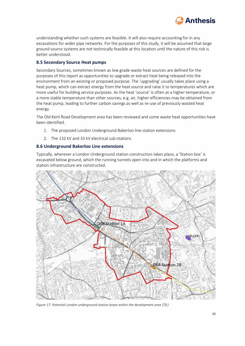
42
understanding whether such systems are feasible. It will also require accounting for in any excavations for wider pipe networks. For the purposes of this study, it will be assumed that large ground source systems are not technically feasible at this location until the nature of this risk is better understood.
8.5 Secondary Source Heat pumps
Secondary Sources, sometimes known as low grade waste heat sources are defined for the purposes of this report as opportunities to upgrade or extract heat being released into the environment from an existing or proposed purpose. The ‘upgrading’ usually takes place using a heat pump, which can extract energy from the heat source and raise it to temperatures which are more useful for building service purposes. As the heat ‘source’ is often at a higher temperature, or a more stable temperature than other sources, e.g. air, higher efficiencies may be obtained from the heat pump, leading to further carbon savings as well as re-use of previously wasted heat energy.
The Old Kent Road Development area has been reviewed and some waste heat opportunities have been identified.
1. The proposed London Underground Bakerloo line station extensions
2. The 132 kV and 33 kV electrical sub-stations
8.6 Underground Bakerloo Line extensions
Typically, wherever a London Underground station construction takes place, a ‘Station box’ is excavated below ground, which the running tunnels open into and in which the platforms and station infrastructure are constructed.
Figure 17: Potential London underground station boxes within the development area (TfL)
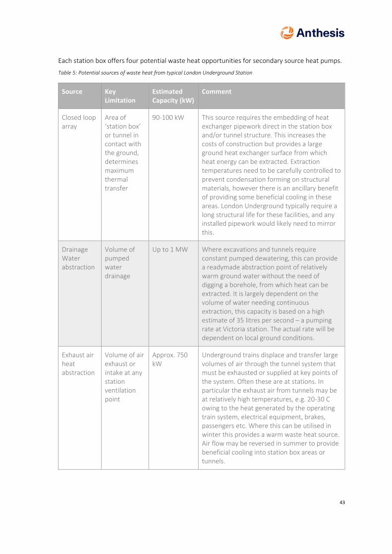
43
Each station box offers four potential waste heat opportunities for secondary source heat pumps.
Table 5: Potential sources of waste heat from typical London Underground Station
Source Key Limitation
Estimated Capacity (kW)
Comment
Closed loop array
Area of ‘station box’ or tunnel in contact with the ground, determines maximum thermal transfer
90-100 kW This source requires the embedding of heat exchanger pipework direct in the station box and/or tunnel structure. This increases the costs of construction but provides a large ground heat exchanger surface from which heat energy can be extracted. Extraction temperatures need to be carefully controlled to prevent condensation forming on structural materials, however there is an ancillary benefit of providing some beneficial cooling in these areas. London Underground typically require a long structural life for these facilities, and any installed pipework would likely need to mirror this.
Drainage Water abstraction
Volume of pumped water drainage
Up to 1 MW Where excavations and tunnels require constant pumped dewatering, this can provide a readymade abstraction point of relatively warm ground water without the need of digging a borehole, from which heat can be extracted. It is largely dependent on the volume of water needing continuous extraction, this capacity is based on a high estimate of 35 litres per second – a pumping rate at Victoria station. The actual rate will be dependent on local ground conditions.
Exhaust air heat abstraction
Volume of air exhaust or intake at any station ventilation point
Approx. 750 kW
Underground trains displace and transfer large volumes of air through the tunnel system that must be exhausted or supplied at key points of the system. Often these are at stations. In particular the exhaust air from tunnels may be at relatively high temperatures, e.g. 20-30 C owing to the heat generated by the operating train system, electrical equipment, brakes, passengers etc. Where this can be utilised in winter this provides a warm waste heat source. Air flow may be reversed in summer to provide beneficial cooling into station box areas or tunnels.

44
Source Key Limitation
Estimated Capacity (kW)
Comment
Direct heat extraction
Installed cooling equipment at the station
Equipment dependent, Est Approx. 100 -150kW
This heat arises from any installed cooling equipment at a given station, as required or e.g. staff facilities, station retail or equipment cooling. Where cooling is installed there is an opportunity to reclaim the ‘waste’ heat from these systems.
Total per station 2 MW thermal
Table 5, above, has made generous estimates for a number of these sources. For example, the heat abstraction from the station box flank walls is assumed to be from ‘boreholes’, however the wall does not behave exactly like a borehole as half the surrounding ground volume is in fact air. Similarly, the volume of water assumed to be abstracted is at the high rate of the scale, consummate with one of the higher pumping rates of any station on the tube. The direct heat extraction is likely to be the most variable. Our estimate is based on the cooling need of some small retail outlets, but this will almost entirely depend on the quantity and nature of equipment installed at a given location, particularly transport equipment (e.g. signalling) and retail strategy.
Even with assessments assuming more generous quantities of heat, none of these sources are likely to provide the Multi Megawatts of energy required to supply a wider heat network. Therefore, although integration into a wider district energy system energy system should not be discounted, it is more likely that these sources are better utilised as a local communal heating system supplied from heat pumps. This would be especially recommended where undertaken as a coordinated conjoined project, for example, residential development adjacent to, or above new station facilities. This does not preclude interconnection with a wider district heating system in the area. As long as the local communal heating system is water based (which is considered likely given current trends in refrigeration equipment), be it ambient loop or low temperature direct heating systems, there is no technical limitation to these being linked up with a wider district energy system in the area, for backup and peak supply, or as an alternative dedicated future supply system.
Heat pumps utilised for both heating and cooling exhibit very high Coefficients of performance, as both the heat and coolth outputs are used, (one or other is not rejected or absorbed from the environment) for the electricity consumed. COPs higher than 5 may be possible depending on the scale and context of the system, which are much closer to the performance typically obtained from extracting steam from steam turbines (see z-factor in later sections).
It is therefore recommended that a co-ordinated project approach at each station is undertaken, to assess the likely maximum waste heat extraction from these four thermal energy sources and based on the findings, to describe how to make best use of waste heat locally given the development profile associated with the site.

45
8.7 Electrical sub-stations
Two large existing electrical sub-stations are identified in the development area.
1. New Cross (132 and 66 kV)
2. Verney Road (33kV)
The estimated electrical loads are shown in Table 6 and Figure 18.
Table 6: Large Electrical Sub-stations within the Old Kent Road Development Area
Location Maximum Winter Load
(MVA)
Estimated Heat availability (kW)
New Cross Approximately 316 MVA 1,000
Verney Road Approximately 70 MVA (note this is supplied via New Cross Substation)
250
Figure 18: Location of major electrical sub-stations within the Old Kent Road Development area
Depending on the type and age of transformers, it would be expected that approximately 1-3% of the electrical load would be available as heat. Note this is only during peak demand periods, so is extremely unlikely to be available constantly. The minimum constant loading on the transformers is not available, however typically this would be a third to a half of the winter peak, depending on the specifics of the connected load. From this reasoning we have estimated the available waste heat from these two locations. A better estimate of this would be required through direct engagement with the DNO (UK Power networks) and potentially monitoring of the site.
To access this heat, it is typically required to use transformers with a circulating cooling medium such as oil. It is possible to purchase transformers with additional heat exchanger equipment,

46
usually a second pumped oil to water heat exchanger, which allows for the extraction of heat. Again, this may be upgraded to useful temperatures using a heat pump. To access the heat would require direct engagement with UKPN and likely the entire replacement of the existing HV transformer equipment with new transformers. It is highly unlikely that existing transformers include this equipment or can be modified to provide it whilst ensuring the high levels of availability demanded by the national grid.
As may be observed, whilst these may be useful quantities of heat, they would not represent enough supply to provide a heat source for the entire surrounding area. Therefore, it is recommended that this is considered as a potential solution to an adjacent or conjoined development at these locations, particularly where upgrading of the electrical infrastructure in the area drives transformer replacement. There is an opportunity to co-ordinate this with the wider development areas and make better local use of this waste heat source. Assuming heat is extracted using a heat pump-based solution, and circulated within connected buildings using an ambient loop, or a direct heating circuit this again does not preclude the interconnection of this building with a wider district heating system for backup, peak or alternative future heat supply.
8.8 Other secondary heat sources
It is a requirement of secondary heat sources serving a heat pump, that these produce a continual stream of heat through the heating season, and not only in the summer. Some commercial loads (e.g. data centres) fulfil this criterion, but Anthesis is not aware of any of these being planned within the development and regeneration area. Reviewing the proposed commercial loads, currently it is not anticipated these include a large, continual cooling demand, therefore it is unlikely to be available to provide significant heating to the development area. This does not discount large ambient loop type heat pump systems within development zones, however where these do not include a balanced cooling load, winter heating requirements will be dominated by the source of energy for the peak heat demand. This may be a separate Air Source Heat Pump, or a heat exchanger with the local district heating system both of which are reviewed elsewhere in this document. However, no additional specific secondary heat sources are proposed to be reviewed further in this report.

47
8.9 Fuel Cell CHP
Realistically, any fuel cell installed at the Old Kent Road will need to be natural gas fuelled, as there does not currently exist a hydrogen delivery infrastructure (any hydrogen deliveries would need to be made by tanker, which would be an expensive and potentially disruptive process given the surroundings).
Many of the natural gas fuel cells are, however, of significant size. These are shown in Table 7:
Table 7: Typical gas fired Fuel Cell arrangements and size requirements
Product Size (w/l/h) Image
FuelCell energy, 1.4MW
11.9 x 16.8 x 6.1
FuelCell energy, 2.8MW
13.1 x 21.0 x 7.62
FuelCell energy, 3.7MW
Given as 929m2
In part, this is due to the equipment required to produce Hydrogen from Methane. This is usually undertaken by a process called steam reformation, which is required to take place local to the fuel cell. Steam reformation results in the production of NOx locally, arising from the combustion of fuel to raise steam. Additionally, if the locally produced carbon dioxide is not captured and stored (e.g. using CCS or similar) this cannot be considered a low carbon technology.

48
Given the constraints of the urban environment at Old Kent Road, a fuel cell CHP with Carbon Capture and Storage is likely to be unfeasibly large. As such, it is not recommended that this technology is progressed.
8.10 Connection to SELCHP
SELCHP, or South East London Combined Heat and Power, is an energy from waste plant located in South Bermondsey.
Figure 19: The SELCHP facility
For many years only generating electricity, the plant has, since 2013 provided heat and hot water to several estates located around Bermondsey, specifically:
• New Place Estate (Four Squares) • Keetons Estate • Rouel Road Estate • Slippers Place • Abbeyfield • Pedworth Estate • Silverlock Estate • Tissington • Silwood Estate
A number of meetings were held with Veolia, managers of SELCHP, in order to establish the viability of extending the current scheme scope to connect the development taking place within the site allocations. Veolia themselves also have an ambition to connect to several existing estates located to the South of the opportunity area. Currently the facility has a planned ability to increase heat take off from the current system (circa 12 MW thermal peak), to 40 MW thermal peak. Additional heat beyond this is available from the facility, the total thermal capacity is 135 MW, from which 35 MW electricity is produced, though additional heat extraction would require additional equipment, design and integration.

49
The following should be noted in relation to a connection to SELCHP as the heat source:
• SELCHP’s ambition of connecting to existing estates to the south of the opportunity area has potential benefits in terms of “kick starting” the network. These estates, being already in existence would form anchor loads that would allow the development of the network out to them. This then means that new loads would be able to connect to the network when built out. This avoids the “chicken and egg” situation that can occur with networks supplying new development (i.e. it can be difficult to get a network built out before there are any loads to connect it to, but conversely, developers are reluctant to design new build to connect to a district heating network before there is one in place).
• Heat from SELCHP could effectively be considered as carbon and NOx neutral, as the plant is operating in any case. The environmental accounting is, however, discussed in more detail below.
• Good negotiation with Veolia would be key in order to ensure that a financially advantageous heat price can be achieved.
Table 8 summarises some of the key facts associated with the supply of heat from SELCHP:
Table 8: Key parameters for SELCHP
Factor Comment
Plant thermal capacity 135 MWth
Currently 35 MWe and 40 MWth available
Current carbon factor 0.058 kg CO2/KWhth
Current NOx emissions 0.00035 kg NOx/kWh Thermal based on 2016 figures.
Flow temperature setpoint of current DH network
110°C
Return temperature from current DH network The system is designed for a 70°C return temperature; however, the lowest observed temperatures are currently 80°C. It is expected that this will drop with expansion of the network, and SELCHP have requested as low return temperatures as feasible from new connections
Pressures Primary network: 5 bar at SELCHP during the summer, and 4.9 at the end point of the network, with a ΔP of 3 bar. During the winter the network operates with an operating pressure of 8.5 bar at SELCHP. An extension of the network would likely see pressures rise. The primary network is understood to be rated to PN 16

50
8.10.1 Resilience and Availability
Back-up/ top-up heat supply would also need to be in place. It is understood that the estates currently connected to SELCHP have maintained their existing boiler plant which operates to top-up heat and provide back-up where required.
In terms of SELCHP non-availability, we were provided with the following by Veolia:
“The hours SELCHP is offline depends if the turbine is being fed with steam or not. Every 2 years we have a common outage which turns the turbine off completely for the planned maintenance and, in interleaved years, we continue with the turbine running, shutting off each boiler in sequence. This means the system would be half the capacity but because normally it's summer, the heat demand is minimal and SELCHP continues to supply the network with heat”.
• 2016: The turbine was offline for 3 days • 2017: SELCHP was operational all year • 2018: The turbine was offline for 15 days
The gas usage for conventional gas boiler plant in the current model envisages 1500MWh per year which represents approximately 20 days during the summer or 8 days during winter. Within the section ‘Energy Section location assessment’ we describe two nearby large local authority boiler houses:
• Brimmington Boiler House
• North Peckham boiler house
These have potential to be directly integrated into a wider scheme, and depending on the nature of integration, offer increased resilience to the network, potentially additional peak load capacity and local pumping assistance to longer distance heat distribution.

51
8.11 Summary of heat generation technologies
The preceding sections contain our analysis of the differing heat supply technologies. These are summarised in Table 9, together with our view on the technologies to take forwards.
Table 9: Summary of key Low Zero Carbon Energy Sources
Primary heat source
Comments and proposed next steps Consider further?
Gas-fired CHP (natural gas/ biogas)
Well-proven technology, with numerous off-the-shelf systems available. Requires suitable electrical loads to supply in order to maximise financial performance and may not comply with air quality positive legislation. Despite this, we recommend that this technology is examined as a potential heat source for the OKR networks, if installed in conjunction with SCR exhaust gas treatment to mitigate local air quality impact.
✓
Fuel cell CHP Zero emission, and potentially as efficient as reciprocating engine plant. However, it is still largely a nascent technology, and as such there are relatively few suppliers of off the shelf (i.e. well-proven) solutions. Those solutions that do exist, especially those fuelled by natural gas, are very large and of a scale that could not easily be accommodated at the site, especially where Carbon capture and storage is required for this to be counted as a low carbon fuel. As such, we do not recommend that this technology be pursued.
Biomass Although it has lower carbon emissions than several other technologies, biomass has unacceptably high levels of particulate and NOx emissions. In addition, space is required for fuel and ash storage and the vehicular movements to transport these.
Air source heat pump
Air source heat pumps may form part of the heating solution at Old Kent Road. Considerations are required into current and future impacts of changes to refrigeration legislation on design, including general environmental health and safety (including noise) as well as potentially fire risk in some cases. Careful integration into building design to meet performance and aesthetic requirements will also be required. Logistical and delivery requirements may also need to be accounted for the largest (1 MW Thermal plus) equipment considering this is an area close to central London. Electrical infrastructure requirements, including enhanced supplies will require accounting for, however both ‘ambient loop’ and block based direct heating systems may be feasible, and will be tested further.
✓
Ground (water)source heat pump
Ground source heat pumps offer the potential for improved operational efficiency, however currently it is not certain that capacity will be available in this location to meet the potential required heating load. Additionally, there appears to be the potential for contaminated land across areas of the development, the risk of which required better understanding before planning to install, in particular, open loop borehole arrangements. This technology has not been taken forward for qualitative review, except for the potential secondary heat sources described below.
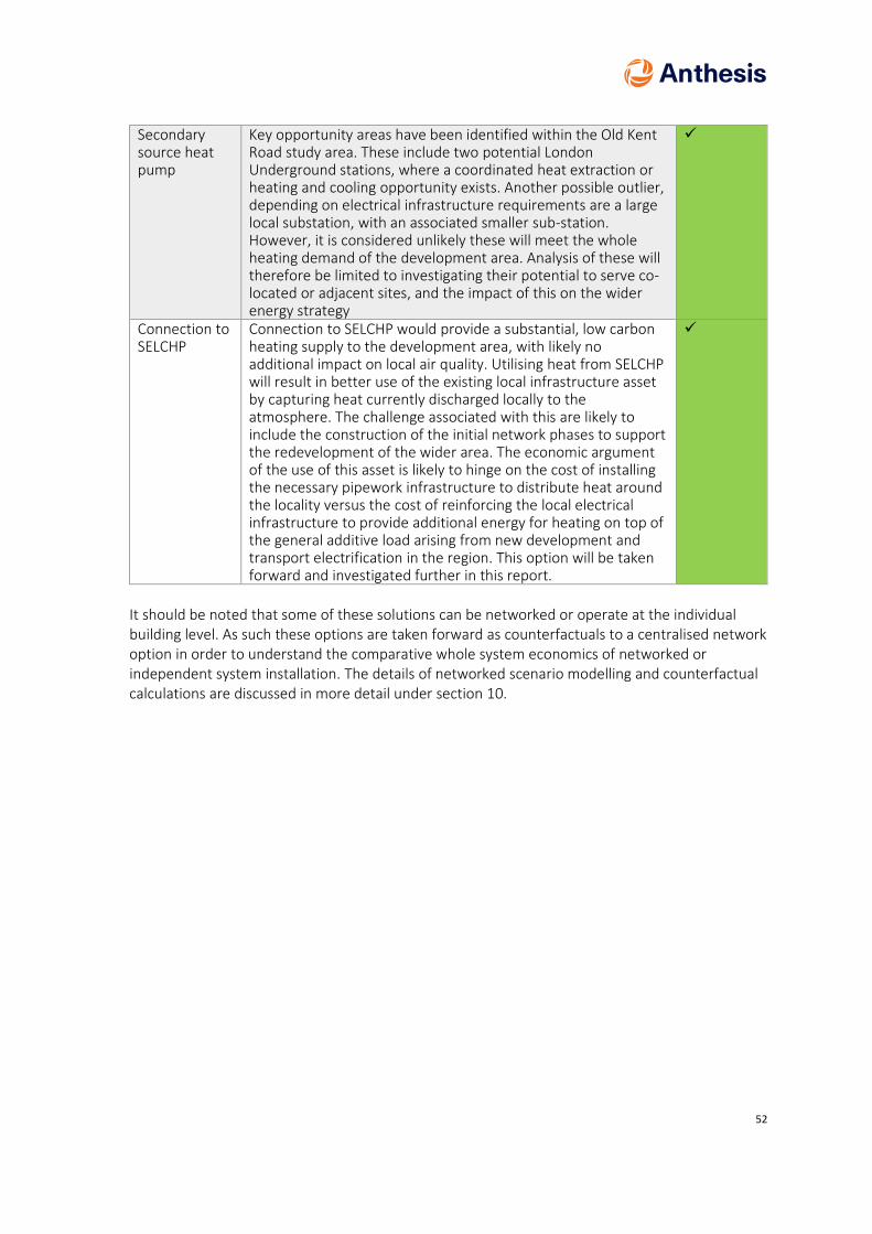
52
Secondary source heat pump
Key opportunity areas have been identified within the Old Kent Road study area. These include two potential London Underground stations, where a coordinated heat extraction or heating and cooling opportunity exists. Another possible outlier, depending on electrical infrastructure requirements are a large local substation, with an associated smaller sub-station. However, it is considered unlikely these will meet the whole heating demand of the development area. Analysis of these will therefore be limited to investigating their potential to serve co-located or adjacent sites, and the impact of this on the wider energy strategy
✓
Connection to SELCHP
Connection to SELCHP would provide a substantial, low carbon heating supply to the development area, with likely no additional impact on local air quality. Utilising heat from SELCHP will result in better use of the existing local infrastructure asset by capturing heat currently discharged locally to the atmosphere. The challenge associated with this are likely to include the construction of the initial network phases to support the redevelopment of the wider area. The economic argument of the use of this asset is likely to hinge on the cost of installing the necessary pipework infrastructure to distribute heat around the locality versus the cost of reinforcing the local electrical infrastructure to provide additional energy for heating on top of the general additive load arising from new development and transport electrification in the region. This option will be taken forward and investigated further in this report.
✓
It should be noted that some of these solutions can be networked or operate at the individual building level. As such these options are taken forward as counterfactuals to a centralised network option in order to understand the comparative whole system economics of networked or independent system installation. The details of networked scenario modelling and counterfactual calculations are discussed in more detail under section 10.

53
9 Energy Centre Location Assessment
The changing nature of climate policy in the UK and London, particularly the falling carbon content of UK electricity, combined with increased policy focus on air quality significantly impacts the technical supply options in the Old Kent Road Area. The options to meet the scale of proposed demand in the OKR area are therefore limited to heat pump type systems or large District Heating Infrastructure.
9.1 Implications of the use of Heat pumps on Energy Centres
With respect to Heat Pumps there are broadly three current commercially available technical solutions.
1. Individual systems – self-contained to a house or apartment 2. Communal systems- contained to an apartment block, using either an ambient loop type
system (heat pumps in each property on a communal water loop, with heat energy injected or rejected from the loop) or a communal heating system with off the shelf large air source heat pumps (approx. 1-2MW thermal systems)
3. Large, custom built, high temperature refrigerant heat pumps serving district heating infrastructure
Individual systems do not require energy centres. However, they are likely to require space within a property for thermal storage, and externally for the air heat exchanger. This space requirement is discussed in section 13.
Communal systems led by air source heat pumps are likely to be limited by two factors, firstly by equipment which is commercially available off-the-shelf, currently in the 1-2MW thermal range per unit, and secondly by suitable plant area. Communal heat pumps are likely to be located at roof level because of the need to manage the risk of refrigerant leakage and to ensure continuous air flow around the unit. It is therefore considered unlikely that communal systems utilizing this equipment will require energy centres that extend beyond the boundaries of a block’s thermal fabric.
Large custom-built heat pumps, arising high temperature hot water for use in a communal system from a large environmental heat source, for example a river or the ground are by their nature complex pieces of industrial equipment, potentially with large volumes of captured chemicals in gaseous and liquid form. As a result, these are likely to require a dedicated energy centre to operate safely within. However, it is considered unlikely that such a system will come forward at the Old Kent Road, to serve the wider area (please review the technical economic analysis, section 14) with the presence of a large heat source (SELCHP) in the vicinity. It is more likely that any such system would be integrated as part of an existing heat network comprising SELCHP and may in turn have access to a major waste heat source such as the Thames as a result of this integration. The hydraulic implications of this are discussed in further detail in section 11.

54
9.2 CHP Energy Centres within the Old Kent Road Development area
CHP Systems with gas boiler back up and suitable exhaust gas treatment equipment may still be an acceptable strategic response in certain locations of the development. NOx emissions arise wherever combustion takes place, therefore occur from both CHP and gas boilers. As CHP consumes a greater amount of gas than a gas boiler, to produce local electricity as well as heat the quantity of NOx emissions produced locally may be larger despite a similar rate of production from both equipment. Up to approximately 250 kW electrical CHP capacity it may be possible to control emissions to an appropriate level using passive exhaust treatment equipment such as Catalytic convertors. However larger CHP engines are generally then turbo-charged to improve electrical efficiency, which can limit the use of some forms of exhaust treatment equipment. Generally larger CHP units require Selective Catalytic Reduction (SCR) equipment to then treat their exhaust, similar to that used in diesel engines. This typically sprays an ammonia based chemical (in diesel vehicles this is known as AdBlue) into the exhaust stream to chemically react with NOx so it is reduced to very low levels. Combined with a tall flue which allows for effective dispersion of any remaining pollutants, these systems can have very low NOX emission levels. These may even be lower than the rates produced by Ultra-low NOX gas boilers, with these becoming the largest pollutant emitter on site. It may be possible, once SCR is deployed at an energy centre, to also use additional equipment to further reduce the emissions of the gas boilers, though this will increase the operational cost of the system and therefore is likely to impact the heat charge.
Owing to the increased policy focus on air quality, and historic issues with air quality within and around this area of London, it is likely that this additional exhaust treatment will be required if this equipment is chosen to be deployed across the Old Kent Road area.
Figure 20: Major Sub-station and proposed energy centres
With respects to CHP based Energy centres Figure 20 provides details of some key considerations. The major substations are located in the ‘South’ plot. These are important because the closer to these any CHP is located the more likely it is to reduce costs for connection, as well as opening up opportunities to connect higher up the electrical distribution system (e.g. 33 kV over 11 kV) which may help ease constraints or minimise the cost of reinforcement. It will also likely maximise the beneficial use of the electricity in the local area, where it is generated. The location of these will
55
assist with any connections by CHP in the south, west or north plots, though is currently envisaged to be the less likely scenario.
AECOM in their report previously proposed an energy centre in the centre of the West plot. This has a number of technical and practical advantages. It is where development is envisaged to first widely start, meaning the early construction of this would fit with overall development phasing. It is also close to the centre of the development area, helping to minimise he distribution loss from the heat network. However, we consider it unlikely that a new, large scale custom built energy centre is likely to be constructed for the use of the entire development whilst the SELCHP facility with its existing heat network (indicted) is close by.
The North West area of the Old Kent Road Re-development may be one exception. With reference to the techno-economic model, there may be a case for a traditional gas-CHP based energy centre at this location independent from a District Heating network closer to the SELCHP facility. This would likely be of a facility integrated into one of the local redevelopments, usually in the basement, and in turn, likely be highly influenced by any Local Authority Air Quality restrictions on the use of combustion systems. We would consider the most likely location to be within the large redevelopment of the warehouse facilities, which is indicated as a ‘zone’ within Figure 20. The electricity from CHP would then be available to be sold via private wire distribution to these commercial premises. Electrical Demand within a warehouse is likely to depend on its occupation, however we can foresee see a large electrical demand for fleet vehicle recharging assuming the new facilities continue the trend of being associated with local parcel and package distribution. Within the zone, the likely location of an CHP based energy centre would be beneath the highest building planned, owing to the requirement for a flue and restrictions on the dispersion impact of this on adjacent properties. As the details of any proposed development are currently unknown, we have left this indicated as a ‘zone’, as opposed to a specific location until additional information is available.
9.3 Additional Energy Centres supporting a SELCHP District Heating system
If a district heating network based around SELCHP were pursued, there are two key additional energy centre locations outside of the Old Kent Road development area. These are large standalone boiler houses forming part of nearby Local Authority (Southwark) heating systems.
• Brimmington boiler house is a large Medium Temperature boiler house (120C supply) with existing capacity for 12MW of thermal gas heating.
• North Peckham Boiler House is a second Medium Temperature boiler house supplying a large housing estate area with an estimated 20 MW thermal of capacity, including dual fuel (oil) redundant systems.
Other facilities also exist at existing plant rooms at other estates and schools, however these two locations are the largest stand alone facilities in the locations surveyed to date. In the event of an extension of a District heating scheme from SELCHP into this area these two sites have key characteristics for the system. Critical decisions about the integration of these are required by any future system operator and the local authority.
Both offer the potential to provide substantial back up or reinforcement to a local thermal network. The exact nature of integration, particularly hydraulic, pumping and control arrangements will have a large impact of the nature of a local system, including the Old Kent Road area. For example, one or both of these may form part of a resilience strategy to provide heating energy to the Old Kent Road Area in the event of a plant shut down at SELCHP, or top up thermal capacity to the region should demand exceed the current available heat that can be captured at SELCHP.

56
The exact use and integration of these facilities into a wider District Heating system serving the Old Kent Road Redevelopment area will be a critical next step in the detailed design process and the development of an Outline Business Case (OBC) for project investment.
9.4 Energy Interface within development blocks
Assuming a district heating solution fed from SELCHP is taken forward, this will require an energy interface at each development plot between the district heating system and the primary network. It is not envisaged that the primary network will be widely distributed within the buildings owing to the operating temperatures and pressures of this system. It is assumed that a hydraulic break and energy transfer system, typically referred to as a ‘Thermal substation’ will be required.
Figure 21: Typical Twin Plate Thermal Sub-station equipment schematic
It is important to highlight that the SELCHP network operates in excess of 100 C, therefore has a localised risk of steam flash off on the primary, and potentially secondary system sides. As a result, suitable health and safety precautions will be required locally in consultation with SELCHP to mitigate this risk. These may restrict the location such equipment may be situated within a development. Examples of these for consideration on a case by case basis at each development include:
• Restricting access to thermal sub-station areas to competent staff only
• Where feasible designing out the installation of such equipment in ‘confined’ spaces,
• Safe discharge of safety valves to mitigate steam scalding risk (e.g. externally)
• Designing for safe maintenance on live systems – e.g. lockable double isolation valves on secondary side systems for safe isolation
• Planning for catastrophic equipment failure – e.g. providing gravity drainage in plant area rated to discharge a full-bore secondary or primary pipe failure at operating temperatures. Building plant room partitions from materials resistant to high temperature

57
flooding incidents. Bunding areas susceptible to flooding OR protecting sensitive equipment e.g. by bunding electrical switchgear or risers.
• Planning for Fail Safe – e.g. planning for safe secondary equipment shutdown in the event of local plant failure
Low Return temperatures under all load conditions are critical for the success of all efficient, and economic district heating systems and the SELCHP system is no exception. To this end the design parameter set out in CIBSE guide CP1 Heat Networks: Code of practice for the UK have been assumed for connecting parties to date. The authors of this report are aware that updates to CIBSE CP1 are proposed in the near future. Whilst these are unavailable to date it would be reasonable to assume that once published, the design parameters and guidance in the update supersede the current version unless there is an underlying justifiable technical conflict with statutory or safety standards, SELCHP requirements or equivalent.
It is anticipated this will allow the future proofing of the scheme and for a potential future reduction in operational flow temperatures Secondary side systems should be designed to produce return water at <40 °C under all load conditions, with the focus being on achieving the lowest practicable return temperatures throughout design. CP1 also recommends secondary side system temperatures of no more than 70C for heating and hot water within buildings.
By complying with this guidance, the return temperatures to SELCHP may be tweaked by the addition of plates in heat exchangers, or the replacement of heat exchangers at a later date. In particular, lower return temperatures will assist in lower primary capital expenditure, by reducing the supply pipe size required for a given capacity, as well as providing the option for the SELCHP scheme to transition to lower primary operational flow temperatures in the future without requiring the replacement of the secondary distribution system.
It is important to flag that the flow temperature in CP1 guidance is maximum recommendation. There are no restrictions on a connecting party selecting a lower operational flow temperature for their requirements (e.g. 65 C) as long as minimum return temperatures are achieved. This may assist in for example increasing flow rates in systems which are struggling to achieve the return temperature requirement owing to the large temperature difference required when operating at the maximum flow temperature. This also does not preclude the use and future connection of ambient loop type heat pump systems, providing they operate at suitably low temperatures.
A correctly designed and commissioned conventional variable flow secondary distribution system utilising 2 port control valves and minimal bypasses should see return temperatures fall when operating at part load.
The connecting parties should also identify their anticipated minimum operating load. Plate heat exchangers in thermal substations have restrictions on minimum turndown before they begin to operate in potentially an incorrect manner. For low turndowns, dual (sometimes more) plate sub-stations may be required, with potentially dual control valves of differing sizes in parallel per plate, in order to obtain the correct control authority and thermal transfer characteristics at low load.
Low flow rates in the secondary system entail small openings in valves, as well as narrow passageways in heat exchangers. Therefore, water quality is equally important on secondary systems to prevent blockages or equipment damage failure including at the thermal substation. It is recommended that connecting parties employ a water quality expert as part of their design team, and as a minimum commission in line with the BSRIA Water Treatment and Commissioning Guidance set and demonstrate as achieved the BSRIA system water quality standards. However, connecting parties should pay close attention to the water quality standards required in fittings operating with a wide temperature differential (e.g. PITRV valves) as these often themselves

58
require differing or higher water quality standards to remain in warranty, e.g. BS EN 14868 and the German VDI guideline 2035 standards.
It would be anticipated that secondary side systems incorporate equipment such as dirt and air separators, test points, automatic side stream filtration, vacuum degassing, water treatment systems such as softeners or Reverse Osmosis, with automatic dosing equipment as necessary to achieve these standards.
Additionally, the first fill of the system may be required to take place in controlled manner, e.g. using tanker deliveries of deionised or treated water, or specialist on-site construction phase water treatment equipment (e.g. Hydrosphere type systems) to prevent raw mains water initiating water quality problems from the outset of construction.
It is strongly recommended electronic water quality monitoring and logging is incorporated on the secondary side, to provide an early indication of deteriorating water quality, and an evidence record in the event of any damage that may the attributed to water quality taking place to heat network equipment. This is in addition to any heat metering required under building and statutory regulation.
Pre-packaged thermal sub-stations are available from a number of manufacturers (e.g. Danfoss), and whilst the authors are aware of no commercial or technical preference for any future scheme, it is recommended that these are approached to determine initial space allowances suitable for the particulars of each development. This should include appropriate space for safe access and maintenance in line with manufacturers requirements, SELCHP requirements and the CDM regulations.
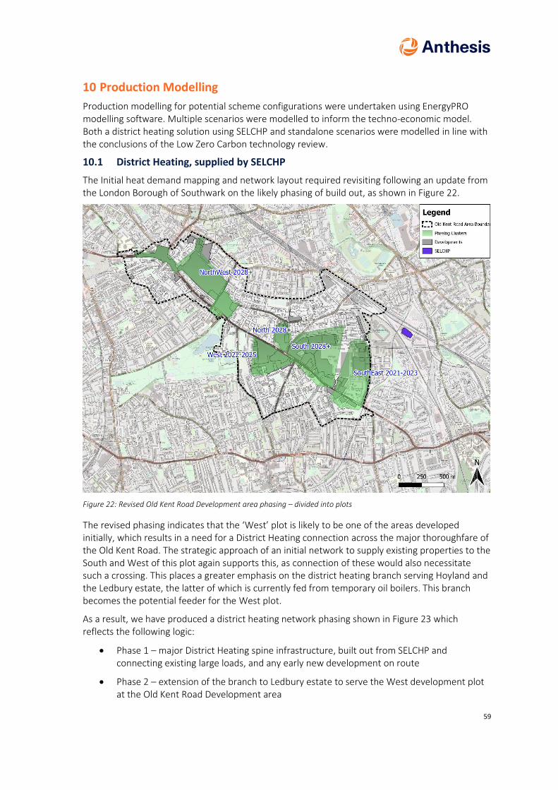
59
10 Production Modelling
Production modelling for potential scheme configurations were undertaken using EnergyPRO modelling software. Multiple scenarios were modelled to inform the techno-economic model. Both a district heating solution using SELCHP and standalone scenarios were modelled in line with the conclusions of the Low Zero Carbon technology review.
10.1 District Heating, supplied by SELCHP
The Initial heat demand mapping and network layout required revisiting following an update from the London Borough of Southwark on the likely phasing of build out, as shown in Figure 22.
Figure 22: Revised Old Kent Road Development area phasing – divided into plots
The revised phasing indicates that the ‘West’ plot is likely to be one of the areas developed initially, which results in a need for a District Heating connection across the major thoroughfare of the Old Kent Road. The strategic approach of an initial network to supply existing properties to the South and West of this plot again supports this, as connection of these would also necessitate such a crossing. This places a greater emphasis on the district heating branch serving Hoyland and the Ledbury estate, the latter of which is currently fed from temporary oil boilers. This branch becomes the potential feeder for the West plot.
As a result, we have produced a district heating network phasing shown in Figure 23 which reflects the following logic:
• Phase 1 – major District Heating spine infrastructure, built out from SELCHP and connecting existing large loads, and any early new development on route
• Phase 2 – extension of the branch to Ledbury estate to serve the West development plot at the Old Kent Road Development area

60
Figure 23: Proposed District Heating Network Phasing approach in Old Kent Road Area
Future phases are broken down into the development area descriptor as once phase 1 and phase 2 is complete, there are multiple points of access to development plots in the North and South zones. It is assumed further roll out of the district heating system to individual development plots would be progressed on a ‘most economic basis’ i.e. the network would expand from the closest logical connection point, to provide a supply with the lowest capital cost for a given energy need. Various possible routing options are demonstrated in Figure 24.
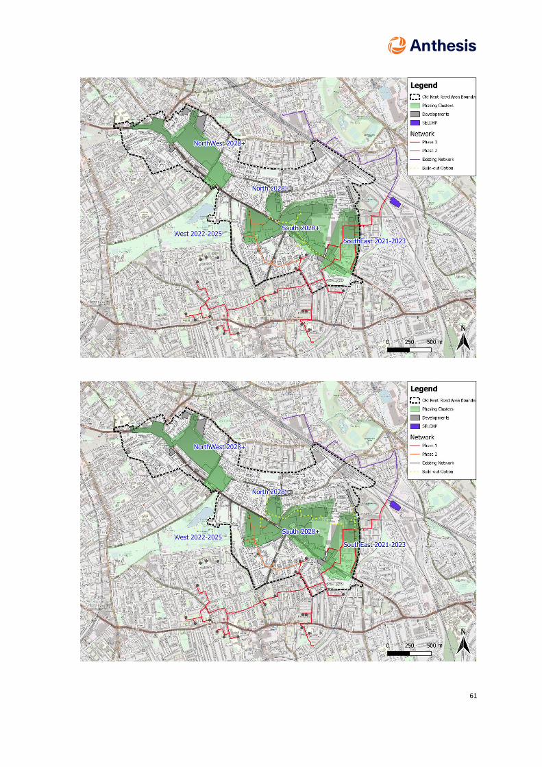
61
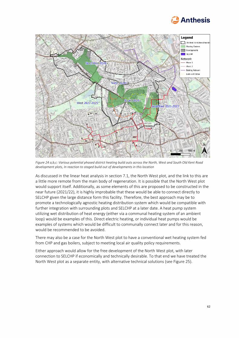
62
Figure 24 a,b,c: Various potential phased district heating build outs across the North, West and South Old Kent Road development plots, In reaction to staged build out of developments in this location
As discussed in the linear heat analysis in section 7.1, the North West plot, and the link to this are a little more remote from the main body of regeneration. It is possible that the North West plot would support itself. Additionally, as some elements of this are proposed to be constructed in the near future (2021/22), it is highly improbable that these would be able to connect directly to SELCHP given the large distance form this facility. Therefore, the best approach may be to promote a technologically agnostic heating distribution system which would be compatible with further integration with surrounding plots and SELCHP at a later date. A heat pump system utilizing wet distribution of heat energy (either via a communal heating system of an ambient loop) would be examples of this. Direct electric heating, or individual heat pumps would be examples of systems which would be difficult to communally connect later and for this reason, would be recommended to be avoided.
There may also be a case for the North West plot to have a conventional wet heating system fed from CHP and gas boilers, subject to meeting local air quality policy requirements.
Either approach would allow for the free development of the North West plot, with later connection to SELCHP if economically and technically desirable. To that end we have treated the North West plot as a separate entity, with alternative technical solutions (see Figure 25).

63
Figure 25: Potential stand-alone district heating network in North West Plot of the Old Kent Road Development area
The current development plan does not include for any development between the collected North, West and South plots and the North West plot. As a result, there is a branch of potential district heating pipework between the two locations with no supporting additional loading en-Route. We have given this the title ‘the NW link’ (see Figure 26), as it is a standalone element of the network with a potential of operating independently. It represents a capital cost outlay, and a fixed thermal loss to the network, in return for which there is the economic income. There is therefore a straightforward economic consideration - does the income obtained outweigh the capital cost and additional operational losses incurred by the link infrastructure? This has formed another of the scenarios we have tested.

64
Figure 26: Potential full network build out after Phase 1 and Phase 2, including Northwest link
Table 10 summarises the District heating scenarios tested, representing the build out of the network, from initial phase 1, to the build out of the full development with or without the North West plot included as part of the system

65
Table 10: Summary of District Heating Scenarios tested in the Techno Economic Modell
Scenario Label
Scenario Title Comments
A Full Build Out – Pre 2028 loads This represents the full infrastructure costs (i.e. full investment) but with only Pre 2028 loads included in Phase 1 and phase 2. This represents a worse case of full capital spend, but limited income on the initial infrastructure (phase 1 and 2) limited by the development timing
B North, South and West Plots – Pre 2028 loads
This represents a build out limited to the 3 plots clustered around the Old Kent Road. The North West plot is not included. It represents the economic impact of excluding this area
C North West Plot – CHP Stand alone
This represents an alternative scenario where a CHP system supplies the North West Plot only
D North, South and West Plots –SELCHP with North West Plot CHP stand alone
This is a combination of scenarios B and C, representing the amalgamation of these strategies. Please note – the economic effect does not represent the validity or otherwise of the individual projects
E Phase 1 only, pre 2028 loads The economics of the first phase of construction, where large Capital expenditure is required to account for ground risk and large scale pipework for future phases
F Full Build out – All loads Full build out of all currently anticipated loads on the network. This represents the current best case scenario
G North West Plot – Heat Pumps only
This represents an alternative scenario where a Heat Pump system supplies the North West Plot only
H North, South and West Plots –SELCHP with North West Plot Heat Pumps stand alone
This is a combination of scenarios B and G, representing the amalgamation of these strategies. Please note – the economic effect does not represent the validity or otherwise of the individual projects

66
10.2 Counterfactuals to District heating
District heating is just one of the potential technical heating solutions under consideration around the Old Kent Road. The alternative scenarios presented here relate to different types of heat infrastructure that could equally be installed to meet local planning requirements. To compare the systems the following assumptions have been made:
1. All anticipated development loads are compared against each other, no phasing or plot separation (e.g. the NW plot separately) is considered
2. District heating scenarios include for network losses at 10%, and riser losses of 15% 3. Communal heat pumps are assumed not to have network heat losses, and an annual
Coefficient of Performance (COP) of 2.31 (varying with outdoor temperature). Riser heat losses are included
4. Individual Heat pumps are assumed to have no riser heat losses and a COP of 1.7 (varying with outdoor temperature). This matched the current SAP ‘in-use’ assumption for small heat pumps, and reflects the reduction in efficiency that is inherent with small equipment versus large equipment
5. Existing systems served by District Heating, are modelled as continuing to be used with new gas boilers, with an improved efficiency of 75%
This allows the comparison of 3 broad approaches, which have been termed ‘Counterfactuals’ in this report.
1. District heating (under a range of build scenarios) 2. Communal Air Source Heat pumps for new build and continuation of existing gas
infrastructure for existing buildings 3. Individual Air Source Heat pumps (per property) for new build and continuation of existing
gas infrastructure for existing buildings
Table 11: Summary of Counterfactual Scenarios tested in the Techno Economic Model
Counterfactual Scenarios Comments
District heating – Scenario F This represents the full build out of the network, and is the comparable scenario to the following counterfactuals
Communal Heat Pumps (New Build) Gas Boilers (Existing)
This represents an alternative proposition for the full build out. In new buildings, where adaptation to building fabric is not required a communal heat pump system is assumed. Where existing buildings form part of the district heating scenario, these are fed from new gas boilers, with an uplift in efficiency.
Individual Heat Pumps (New Build) Gas boilers (Existing)
This represents a further approach where the preferred communal energy distribution infrastructure to new build flats is electrical to every apartment. Gas boilers remain. Where existing buildings form part of the district heating scenario, these are fed from new gas boilers, with an uplift in efficiency.

67
11 Hydraulic modelling
An initial network route was planned from SELCHP to the identified points of connection in existing facilities, and to serve the new build areas of the Old Kent Road. This network was sized and modelled in dedicated hydraulic modelling software assuming the following parameters:
Table 12: Hydraulic model parameters
Parameter
Flow Temperature 110C
Return temperature 75C
Planned Pressure drop 200-300 Pa/m
Velocity Limits < 50 mm nominal diameter – 1.5 ms-1
>50 mm nominal diameter – 3.0 ms-1
Loads Estimated Peak – dominated by Residential DHW type loads
Minimum index pressure (Dynamic) 1 bar
Pump location SELCHP
The modelling software estimates pipe sizing based on 1st principles at a steady state. The modelling excluded the impacts on pressure and flow requirements of the existing network (currently unknown) but did include for pressure drops in heat exchangers, including a notional pressure drop at Heat Exchanger equipment at SELCHP. This is a large network, operating at high temperatures (above 100 C), therefore there are increased risks with the hydraulic system, for example:
• Risk of local steam explosion from uncontrolled pressure release
• Water hammer or Surge
These were not considered in detail using this model, as no dynamic analysis was undertaken, and velocity limits were selected to reduce the general likelihood of some of these hydraulic effects from occurring. The outputs of the model are presented in Appendix F.
Key findings from the hydraulic analysis were:
• High dynamic pressures may be required to serve the most remote loads (circa 25 bar). Although new pipework is available rated to these levels, existing pipework is understood to be rated to PN 16 (lower than 25 bar). Therefore, to avoid the replacement of existing pipe it is likely an alternative pumping strategy may be required, with remote pumping stations, or equivalent, to reduce the combined effects of static and dynamic pressure to below the rating of existing pipework.
• The hydraulic model (and pipe sizing) is most sensitive to temperature differential. Lower return temperatures allow the use of smaller diameter network pipes, with lower capital cost and lower thermal losses, as a greater quantum of thermal energy is delivered per

68
unit of water. Similarly, failing to achieve the specified return temperature results in capacity restrictions which prevent the distribution network from delivering the required peak load.
• Varying the allowable pressure drop at peak load, did not result in substantial differences in pipe sizing.
Therefore, the selection and achievement of a return temperature is key for the proposed system. Not only does this reduce the capital outlay, and the thermal losses of the system, but longer term this facilitates the use of complimentary renewable heating systems on a wider network assisting with future proofing the infrastructure. For example, were a return temperature of 55 C to be achieved, the flow temperature may be reduced seasonally or permanently to 90 C, with approximately the same hydraulic capacity available with the pipes as estimated at current parameters. At these conditions the use of large-scale high temperature heat pumps would become technically feasible, with heat extraction from the Thames a potential opportunity for a wider network at this location.
Figure 27: Excerpt from Initial Hydraulic model calculation, detailing estimated pipe sizing
The current hydraulic analysis does not consider dynamic hydraulic effects and is not suitable for detail design at this stage, particularly without a clear design resolution on approaches to pumping, pumping control and network pressure distribution. It has been used at this stage to estimate pipe sizing, which has then formed the basis for the risk assessment and capital cost estimate in this study.
It is recommended a detailed dynamic hydraulic model is conducted to finalise pipe sizing and pumping strategy, once a target return temperature is agreed from the network operator. This may include differing targets for existing and new build schemes, e.g. less than 75 C in existing

69
(lowered in advance where feasible) and less than 40 C in new build (i.e. designed low from the outset). Additionally, a pressure loss or velocity limits at peak should be agreed based on dialogue with network manufacturers, the designers and operators. A higher pressure loss, or velocity may be acceptable during infrequent peak operating conditions, which a temporary pumping energy efficiency loss for a short duration, versus a larger pipe size and a greater thermal loss over long durations. This should also consider a ‘minimal load’ scenario (e.g. 3am in the summer) as a minimum velocity of 0.5 ms-1 is also desirable to move any debris formed in the water system to equipment that can remove it (e.g. strainers, filters etc) before this can become a greater local problem for water quality. Strategies such as seasonally or daily variations in flow temperature profile may assist with this approach, as well as reducing standing losses in ‘off peak’ periods, which form the predominant load condition.
70
12 Energy Distribution
Working with our partners 3DTD, we have provided a range of potential routings for a phased roll out of a district heating scheme, as well as working to identify foreseeable risks along the routes. To support this, we have conducted preliminary Hydraulic modelling to identify likely pipe sizes along the route to serve the identified loads. Full details are available within Appendix F, however in summary, there are a number of complications arising from installing district heating pipe at this location.
12.1 SELCHP and national rail infrastructure
SELCHP is surrounded on 3 sides by national rail infrastructure, making it hard to route pipework away from it. Once pipe is routed away from this area, depending on the routing options chosen, other national rail infrastructure requires crossing. Each rail crossing requires a negotiation and charges payable to Network rail, increasing capital and ongoing operational cost.
An existing rail crossing immediately outside SELCHP is available to allow the first crossing out of the site, having been planned as part of the original District heating system. It is planned to utilise this where feasible. The existing culvert has a size limitation and depending on final pipe size selection this may require a local reduction in insulation thickness to allow for a wider internal bore across the railway.
12.2 Existing Utility Infrastructure
Other large-scale utility infrastructure is present in various locations along the routing. Of particular concern are:
• Large gas infrastructure, including gas governor and gas mains (circa 600mm). In part these are associated with the historic gas works at this location, and competes for road space in certain areas. Diversions of this may be necessary in some circumstances, which where it arises is likely to have a large impact on capital cost
• Trunk Water mains (e.g. 20 inch) which may require deep excavation to pass beneath
• Trunk sewers with potential to obstruct DH pipe works
• Extra High Voltage (e.g. 132 kV cables) associated with the nearby New Cross primary substation and its feeders. These require careful co-ordination to cross to mitigate significant health and safety risk
• British Telecom – Large telecom chambers, particularly near the Peckham road, where historic and current trunk telecoms and data routes are installed
• Historic Tram and railway tracks – in certain locations the road may have been simply ‘laid over’ these, with the rails and sleepers remaining below the surface. Removing these to allow for Pipework installation is likely to be expensive
• Historic Bridges. In certain locations the road my in fact be a bridge structure passing over defunct voids, such as the historic canal network in this location
12.3 Contaminated land
Parts of this area of London have a history of industrial usage, including metalworks, gas works and printworks. These operations are suspected to have contaminated land in the vicinity, which will require the management and safe disposal of soil excavated where pipework is installed.

71
12.4 Old Kent Road
The Old Kent Road is a major historic thoroughfare in London, with origins in the Roman times. There are large volumes of traffic associated with this street as well as underground infrastructure. It has been our aspiration to minimise the crossing of this road owing to the anticipated difficulties in installing large pipework across a major London route. A few routing options are presented in Appendix E, and require further investigation to determine the preferable approach. The immediate aspiration is to cross the Old Kent Road once to serve the new build areas and the ‘West’ plot of redevelopment. We have retained the option for a recrossing of the Old Kent Road to serve developments close to the West plot in adjacent North and Southern plots should this be the economically preferable approach, over extensive network installation across the southern plot.
12.5 Phased installation
As previously described in the ‘production modelling’ section, we propose a phased installation for any District heating network. In broad summary this comprises of:
• Phase 1: Installation of major spine route to large existing estate roads in the Peckham area. The spine route passes by the Old Kent Road development area, facilitating future new build development in the South Zone
• Phase 2: Continued installation from Ledbury branch to serve the ‘West’ plot of redevelopment, scheduled to take place in 2024/25
• Additional phases (provisionally labelled after development zones) to take place expanding from initial phases, via most economic route
12.6 Electrical distribution
In the counterfactual case no district heating pipework would be installed in the roadway. However, there would be a substantial increase in electrical infrastructure required to support the Air Source Heat Pump proposals. The London Borough of Southwark have recently commissioned a report into the additional electrical infrastructure required to facilitate development. Anthesis have prepared a critique of this (available in Appendices) highlighting some critical further considerations for the electrical infrastructure in the area. These include:
• Any Additional electrical capacity required for vehicle transportation. This is currently excluded from the load assessment and would be anticipated to be required in the future. There are 3 main elements to this:
o Personal Vehicle recharging capacity – for future residents
o Fleet vehicle recharging capacity – for proposed on-site warehouse facilities
o London Underground – Bakerloo power supplies (depending on TFL design approach)
• Any enhanced capacity required for electric only cooking and catering
• Any reinforcement requirements for large scale distributed energy – e.g. PV
The report does make a recommendation for allowance of electrical capacity to allow for electric heating. From our modelling of loads we believe this accounts for some form of heat pump electric heating not direct electric heating. There is no consideration of the other impacts of heat pumps on the electrical system (i.e. power quality and surge currents) which may trigger other

72
reinforcement work in the network. Broadly speaking at this stage, we would not disagree with the additional electrical capacity forecast for heating alone of up to 16MVA.
It should be noted that there is a material difference in electrical load driven by the selection of large-scale heat pumps as opposed to individual heat pumps. Efficiency of mechanical systems does not remain constant with equipment size, therefore larger equipment tends to have higher efficiency. Once the gain in efficiency outweighs the losses of a communal heating distribution system a larger communal heat pump is preferable. Smaller individual heat pumps also often require a backup direct electric heater, often an immersion heater in a DHW tank to ‘top off’ the hearing of this up to 60 C. The net result is a decline in real life operation efficiency, the ‘performance gap’. This is recognized in government standard calculations for building regulation, with generic individual air source heat pumps allocated a COP of approximately 1.7, to reflect their lower efficiency and fall back to direct electric heating in some circumstances.
A side effect of this is that an approach based on individual heat pumps increases the demand for electrical infrastructure. Anthesis have estimated this may drive a difference of approximately 2 MVA in demand.
The capital cost in cabling works and transformers, as well as space taken for the electrical upgrades can only be estimated by the utility supplier, as this is specialist works. We have therefore excluded this in our cost models to date. Were this to be included (and these additional costs are typically borne by developers) it would further impact the counterfactual cases presented in the TEM. Further commentary on this is presented later in the report.
Fundamentally there is a direct infrastructure comparison to be made at Old Kent Road, which large scale infrastructure would be cheaper to install, District heating pipe work, or Electrical Distribution network. We are able to estimate the cost of the former, which will be presented in subsequent sections. A comprehensive quote from UKPN would be required to estimate the latter and allow a price comparison. This is unlikely to be feasible without a direct engagement and quotation, paying for associated fees, but would facilitate a comparison (with the above considerations addressed), assisting in addressing this strategic planning decision from a whole life cost basis.

73
13 Energy Centre Concept Design
13.1 SELCHP
The SELCHP facility raises steam which is utilised in a steam turbine to produce electricity. The turbine has tappings to divert steam from it at a variety of pressures to extract heat. Currently it is understood that there is an installation making use of the low pressure and medium pressure tappings, to extract up to 12 MW of heat supply from the system. The current installation includes 30 MW of heat exchangers and the turbine has a further high pressure steam tapping which would allow the extraction of an additional 10MW of heat with the addition of a further heat exchanger. As a result there is the current potential for an additional net 28 MW of heat extraction with relatively minor equipment installation. The capital costs of a district heating system have included for the installation of the high pressure equipment to extract up to 40MW total from SELCHP. Additional heat is available at the facility beyond 40MW but would require more extensive modifications. The maximum heat demand of the entire build out of Old Kent Road is estimated at 40MW thermal, however it should be noted that only 28 MW net heat is currently available from SELCHP owing to the capacity requirement of the existing operational district heating scheme. Alternative approaches may allow a reduction of the peak demand of the proposed network to address this capacity limitation
1. Improved energy efficiency on both the existing district heating scheme and at the proposed new connections to existing estates will free up demand for additional ‘peak’ capacity
2. Improved energy Efficiency in new build properties may reduce peak demand for space heating. However, the modelled peak currently occurs within a morning of a winters day, and is therefore likely to also be driven by Hot Water consumption. Additionally, modern space heat demand has already been reduced substantially by regulation, and there is generally a declining opportunity to reduce load in this manner.
3. Thermal storage may reduce peak loads
4. Reduced connection of loads in some areas would reduce demand. For example, if the North West Plot were not to be connected, peak load drops to 34MW
Alternatively, the additional load could be peak shaved by supporting boilers across the network. It is likely that a mixture of the above may be used to defer capital investment for additional capacity at SELCHP which in turn will improve the business case of any installation.
Phase 1 on the district heating deployment is estimated to require a peak load 25.6 MW. This includes for all new development along the pipework route prior to 2028, therefore does not solely represent the existing load. The baseload (assumed as load required to supply for 80% of the year) is approximately 10 MW for phase 1, therefore there remains a large scope to supply the new development capacity (18 MW available) depending on routes adopted to manage or mitigate the peak demand of the system.

74
Figure 28: Modelled heat demand curve for Phase 1 of the Old Kent Road District Heating development
In conclusion, there is an availability of a large quantum of heat from the existing SELCHP system with minimal modification, and no need for a wholly new energy centre.
As previously noted in the section ‘Energy Centre Location Assessment”, a critical component to the potential SELCHP District Heating system is integration of two large existing standalone boiler houses. Solutions may vary from:
1. At its simplest - bypassing these with a dedicated thermal sub-station, potentially retaining a transfer over from this to legacy boiler systems as a local backup
2. At the most extensive, a full boiler house refurbishment, with new equipment directly connected and incorporated into the primary District heating system
Or a range of combinations in between. The full refurbishment provides greatest flexibility in the final system, as the equipment may be designed to peak lop locally, or even across the network, depending on hydraulic and controls integration. As the potential for variations on the integration and equipment ownership for these facilities is large, and there is no current clear direction on a design or contractual preference, capital costs for refurbishing or integrating these facilities beyond installing a thermal substation have not been included at this stage. The balance of cost and benefits between solutions is likely to determine the route forward and should be considered in the next phase of any technical or business case assessment.

75
13.2 Thermal storage
Thermal storage on a district heating network conceptionally has a lot of advantages. In our modelling in EnergyPRO we have estimated that approximately 750 m3 of water based thermal storage with a 40 Celsius temperature differential across it (31.3 MWh of storage) would reduce the peak load at full build out to below the 28 MW net available from existing tap offs at SELCHP. Additionally, such a quantity of storage would allow SELCHP to continue feeding the district heating network for a short period of time with reduced or eliminated steam draw off from the turbine. This would allow a rise in electrical production, and for example, allow additional revenue capture during high wholesale prices, e.g. the evening Red Tariff rate.
There are some technical challenges associated with this approach on this system:
• The thermal storage would be large, and SELCHP is currently a constrained site
• SELCHP operates at 120C above boiling water temperature (at atmospheric pressure), therefore any thermal storage would be required to be pressurised and classed as a pressure vessel. This restricts the size and form of the vessels (from a manufacturing perspective) and requires additional safety precautions under statutory regulation.
• Alternative forms of thermal storage (e.g. phase change waxes) may be feasible, but are usually commercially novel with the associated risk of this
An alternative approach may be to distribute thermal storage to the secondary side systems in individual boiler rooms. These would operate at below 100C, reducing the risks associated with higher temperature operation, and may be easier to procure off the shelf. Additionally, thermal storage at these locations has the added benefit of smoothing load spikes at the demand, potentially allowing smaller thermal substations to serve a property, with smaller distribution pipework (at a capital cost saving) and promoting a more constant continual draw on the pipe network helping to further reduce network losses. Distributing the storage vessels around the system helps relieve local space constraints at SELCHP. However, this approach also prevents some of the valuable flexible operating modes discussed early, for example reducing stem offtake the incinerator, as the distributed thermal storage is no longer able to support the operation of the whole network, just local systems.
It is likely that a mixture of approaches on the network would provide an optimum solution. Local thermal storage may help reduce pipe sizes and support peak loads at some connections, with some form of centralised thermal storage at SELCHP assisting in meeting peak network loads as well as allowing flexible operation and further revenue generation at this facility.
It is recommended should the SELCHP option be taken forward that a dedicated assessment of optimised thermal storage is undertaken, considering the operating parameters of the primary system, and space locations at SELCHP with connection by connection benefits of local storage. This should include an analysis of the additional revenue generation central storage would facilitate as well as the deferred capital investment on heat reclamation at SELCHP or on district heating pipe and thermal substation investment costs at a given location.
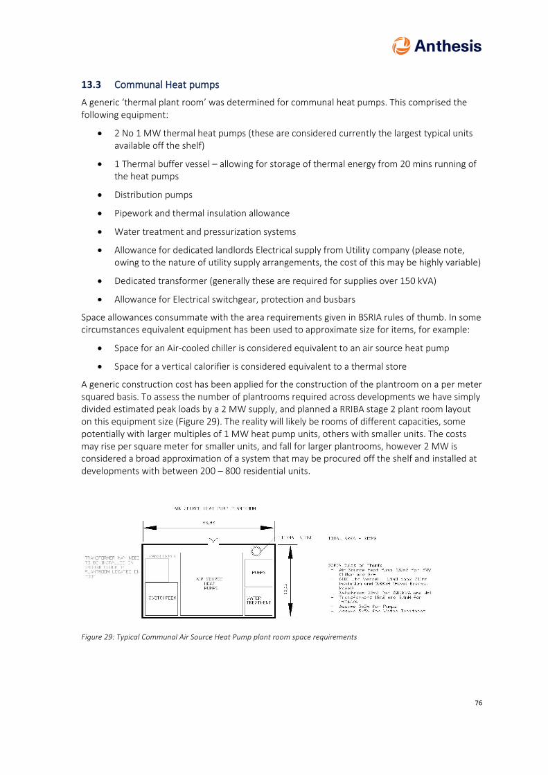
76
13.3 Communal Heat pumps
A generic ‘thermal plant room’ was determined for communal heat pumps. This comprised the following equipment:
• 2 No 1 MW thermal heat pumps (these are considered currently the largest typical units available off the shelf)
• 1 Thermal buffer vessel – allowing for storage of thermal energy from 20 mins running of the heat pumps
• Distribution pumps
• Pipework and thermal insulation allowance
• Water treatment and pressurization systems
• Allowance for dedicated landlords Electrical supply from Utility company (please note, owing to the nature of utility supply arrangements, the cost of this may be highly variable)
• Dedicated transformer (generally these are required for supplies over 150 kVA)
• Allowance for Electrical switchgear, protection and busbars
Space allowances consummate with the area requirements given in BSRIA rules of thumb. In some circumstances equivalent equipment has been used to approximate size for items, for example:
• Space for an Air-cooled chiller is considered equivalent to an air source heat pump
• Space for a vertical calorifier is considered equivalent to a thermal store
A generic construction cost has been applied for the construction of the plantroom on a per meter squared basis. To assess the number of plantrooms required across developments we have simply divided estimated peak loads by a 2 MW supply, and planned a RRIBA stage 2 plant room layout on this equipment size (Figure 29). The reality will likely be rooms of different capacities, some potentially with larger multiples of 1 MW heat pump units, others with smaller units. The costs may rise per square meter for smaller units, and fall for larger plantrooms, however 2 MW is considered a broad approximation of a system that may be procured off the shelf and installed at developments with between 200 – 800 residential units.
Figure 29: Typical Communal Air Source Heat Pump plant room space requirements

77
13.4 Individual Heat Pumps
Individual heat pumps do not require communal plant space. They do however require plant space internally and externally to each apartment. Internal space is typically required for Domestic Hot Water tank. Heat pumps cannot instantaneously produce DHW (unlike combination boilers) therefore need a storage tank where it can accumulate for later peak consumption (e.g. Showers). A storage tank usually holds greater than 110 litres of water, and with requirements for access around the tank to maintain equipment, fixtures and fittings and for inspection (where pressurized) it is usual to occupy approximately 1 m2 of floor area. The floor area is no longer usable by the owner, therefore is typically discounted from the saleable area of a property. The value of 1 square meter of property in London, including in Southwark is substantial, resulting in loss of value to the developer, which will be explored in greater detail later in this report. External area is typically required per apartment for the air heat exchanger and compressor unit. In order to make this accessible in high rise buildings, often the balcony area is utilised. Example equipment is shown in Figure 30. Care is subsequently required to ensure this does not become noise nuisance within the flat, or for neighbouring flats. Installation requirements for individual units tend to be manufacturer and apartment specific, therefore a ‘plant room’ layout of such a system is not presented here.
Figure 30: Example typical Individual Air Source Heat Pump with Packaged Thermal Store
13.5 CHP based District Heating
As discussed in earlier sections, the North West plot may have a case as a standalone system considering the phasing of this area, the distance from SELCHP and the rest of development. As a further counterfactual to a communal heat pump system, a conventional gas fired communal heating system supported by CHP has been explored for this plot. It is recommended that the heating distribution system remains water based to allow future integration with SELCHP. Assuming a conventional gas system is able to discharge local air quality and carbon reduction policy requirements to the local authority’s satisfaction, this would provide an alternative business case for comparison with the heat pumps systems.

78
A typical plant room, depicted in Figure 31 was determined for such a system. This comprised the following equipment:
• Approx. 530 kWe/670 kWth Combined Heat and Power plant, with emergency heat dump and SCR exhaust gas treatment
• Flues and ventilation
• 3 number freestanding condensing gas boilers
• Flues and combustion ventilation allowance
• 1 Thermal buffer vessel – 45 m3 of thermal storage
• Distribution pumps
• Pipework and thermal insulation allowance
• Pipework leak detection
• Water treatment and pressurization systems
• Utility Gas supply
• Allowance for dedicated landlords Electrical supply from Utility company (please note, owing to the nature of utility supply arrangements, the cost of this may be highly variable)
• Dedicated transformer (generally these are required for supplies over 150 kVA)
• Allowance for Electrical switchgear, protection and busbars
Again, a generic construction cost per meter square of plant room has been applied, with plant room meterage estimated using the BSRIA rules of Thumb to a RIBA stage 2 design level (See Figure 31).
Figure 31: Typical CHP Energy Centre/ Plant room requirements
79
14 Techno-economic modelling
14.1 Model structure and core assumptions
A Techno-economic Model was prepared considering the District Heating phased build out, described above with the counterfactual scenarios. Operations were modelled in EnergyPro for a range of loads, with the outputs feeding into the operational cost element of the Techno-economic Model.
The key model outputs can be described as follows:
• Internal Rate of Return (IRR) is a metric used in capital budgeting to estimate the profitability of potential investments. Internal rate of return is a discount rate that makes the net present value (NPV) of all cash flows from a project equal to zero
• Net Present Value (NPV) is the difference between the present value of cash inflows and the present value of cash outflows over a period. NPV is used in capital budgeting to analyse the profitability of a projected investment or project. Time value of money dictates that time affects the value of cash flows. For the scenarios modelled, is based on NPV over 25 and 40 years and using a discount rate of 3.5%.
• Lifetime carbon savings. This is the total carbon savings of the project over 40 years (matched to investment periods). The carbon saving calculation is based on the difference between a proposed DHN and the counterfactual (i.e. Business as usual)
• Simple Payback. Simple Payback period (expressed in years) in capital budgeting refers to the period required to recoup the funds expended in an investment, or to reach the break-even point.
A summary of the high-level techno-economic financial assessment for each network option and counterfactual is presented below.
Compliance with CP1 - This study and its assumptions are based around meeting the requirements of CIBSE/ADE CP1. This extends through design, construction and commissioning through to operation. During operation of the scheme, compliance with CP1 rests on:
• Reducing health and safety risks
• Accurate metering and billing
• Achieving a reliable heat network
• Delivering cost effective maintenance
• Providing monitoring and reporting
• Maintaining building connections
• Minimising environmental impacts
A good operation and maintenance plan is critical to the aim of CP1 to ensure a reliable heat supply. It also reduces customer charges through high efficiencies, longevity of equipment, increased reliability and improved health and safety. Operation of scheme and heat network operator should be certified to ISO 14001 and ISO18001, and all staff trained and competent.
Building connections
The technical aspects of building connections are important to consider as they can be a significant project cost and they form part of the hydraulic strategy for the network. Where possible during site surveys, each main building was evaluated for connection requirements. In converting existing systems that currently use gas boilers consideration has been given to the ease of connecting to the system and the requirements of the connection.

80
The strategy of connections is to use indirect connections (where a heat exchanger separates the network water from the building heating system). Although there is a temperature penalty across the plate heat exchanger there is a commercial and technical advantage to separating the buildings from the network. There are two substantial boiler houses where direct connection may be preferable, with indirect connection closer to demand at individual estates, and integration of the boiler and possibly pumping plant potentially as part of the primary scheme. These are the North Peckham Boiler house and Brimmington boiler house. For now, assumptions are for a new district heating link at these locations with an indirect substation, however it is recommended a cost benefit analysis is undertaken into direct integration of some form, as this may simplify control arrangements as well as assist in providing resilience to the wider area.
Each connection was assumed to include:
• One or twin heating plates heat exchanger sized on peak load,
• Valves, strainers and flow control valves
• Controls
• Heat meter and communication connection
• Small power supply
The costs for the connection also included the underground connection into the building.
14.2 Capital Expenditure (CAPEX)
A significant Capital Expenditure (CapEx) model has been developed around the core scenarios and counterfactuals and these feed into the techno-economic modelling.
The capital costs for all identified opportunities were investigated and the resulting CapEx inputs include costs for plant and equipment supply and installation, distribution pipework supply and installation, trench excavation and re-instatement. Network costs are varied in accordance with identified network constraints, e.g. increased connection costs to account for complex connections to existing buildings and decreased trenching costs for planned developments.
Outline designs, energy centre locations and pipework routes have been determined, as discussed earlier. This has focussed on the clusters with most potential. A full CapEx model has been developed for each scenario and a breakdown of these is shown below. All capital costs include for additional allowances for design (5%), commissioning (2%) and project management (5%). Plant costs allow a contingency of 10%, much larger and specific contingencies have been set aside for the district heating pipework to allow for ground risk, and the potential requirement to divert other utilities.
These CapEx models have been generated using several key sources;
• Anthesis and 3DTD cost database
• Manufacturer quotes/ guidance
• Industry pricing books (SPON’S)
• Quotes for previous projects
• Discussions with manufacturers, suppliers and contractors
Many of these rates have been informed by past projects which have been constructed, bringing a level of comfort to the costing exercise. All costs are commensurate with the stage of project development. Naturally there will be more risk related to costs of “in-ground” works where full surveys are required and this is reflected in the HAZID descriptors and project risk register.

81
Figure 32: A breakdown of the CapEx for each of the scenarios modelled.
The DHN network forms the majority of the costs under most scenarios. This has been derived from Anthesis’ hydraulic model, with each length of pipework / associated fittings costed against benchmark installed cost rates from previously installed jobs, indexed to 2019. Each cluster refined network route was sectioned and defined as soft, medium or hard dig. Each classification has a linear cost per metre dependent on the size of the pipe. This composite analysis allowed us to develop an overall network CapEx cost for each cluster. At the next stage, a focus on risk management in the ground (where civil pipe works take place), pipework sizing, pumping strategy and route optimisation (via dynamic hydraulic modelling) will assist with confirming and mitigating the pipework costs.
14.2.1 Contingency
There is a large contingency set aside for the ground works, which together with the contingency for the capital works represents over 20% of the estimated total capital of the works. The contingency for the ground works was estimated by our partners 3DTD to cover the risk, particularly with larger pipework potentially requiring large utility infrastructure diversions to allow installation. Whilst conducting the Techno-economic modelling it has become apparent that this distorts the economic outputs as it is assumed that all contingency is spent over the course of the project. This may or may not be true depending on the project specifics and final nature of the risk at the point of procurement, therefore we have presented the economic outputs with an assumption that just half the contingency (around 10% of total project value) is spent, then explored within the sensitivity section the implications of spending the full contingency allowance.
82
14.3 Operational Expenditure (OPEX)
Operation and maintenance expenditure have been reviewed and costed so that the information can be entered in the techno-economic model. This information is derived from government survey experience on previous projects and discussions with operators.
To achieve the objectives of the CIBSE HNCoP CP1 it has been assumed that O&M includes (where a technology is present):
• A full LZC (Low or Zero Carbon technology) servicing package is provided that includes a like for like engine / source replacement at 80,000 hours
• Additional costs are included for upgrading the LZC technology plant package every 15 years with like for like replacement. Note this does not include the replacement of the SELCHP waste incinerator plant, where modelled as the supply
• Additional costs are included for servicing and replacing thermal sub-station components every 15 years up to the value of 20% of the original capital
• Annual boiler servicing is included with replacement cost of every 10 years
• Annual individual heat pump and pressurised Hot water store servicing, based on manufacturers recommendations and health and safety requirements
• Annual staff costs are included to manage and operate the scheme, based on BEIS 2015 data.
• Annual maintenance for individual meters to individual properties is excluded for both retrofit and new build properties owing to wide variations in benchmark cost data, and as the current system boundary is drawn at the bulk heat supply point for existing buildings, with little specific information on the new buildings. However it is highlighted that the costs for the maintenance of these in new build and retrofit are likely to arise as a result of heat meters being mandated by regulation (HNMB and building regulations), so unlikely to be a commercial CAPEX ‘option’ in either scenario. They are also likely to affect both systems in a broadly equivalent manner (assumed a consistent additional system cost) and are not dependant on the type of heat supply to the system. It is therefore not considered these will have a material impact in selection of a low carbon heat strategy for the area.
Staff costs for monitoring, metering, and billing have been included. The meters and local BMS are assumed to be connected via a data network to a central data centre for billing and the raising of fault alarms.
Energy centre monitoring will include:
• Fuel consumption, electricity and heat production, operating hours
• Heat produced by each source compared to design
• Monitoring of parasitic consumption within plant room
• Analysed emissions from combustion plant annually and calculated carbon intensity of heat monitored against design.

83
Network monitoring will include:
• Monitoring of levels of heat loss – customer meter readings and plant room exit.
• Monitoring of temperatures and pressures
• Monitoring of pressure difference across strainers
• Monitoring of makeup water volume added
• Monitor leaks via leak detection system
• Chemical dosing to control pH, oxygen levels
• Heat substation/Connection O&M
• Softening of make-up water.
• Inspections of valves
• Suitable HSE procedures put in place to deal with leaks in the network. The following key OPEX input assumptions were made in the operational and Techno-economic model.

84
Table 13: Techno Economic Model parameters - OPEX
Parameter Assumption Source
Weather Conditions (Temperature)
CIBSE Test Reference Year – London 2016
CIBSE
Gas Price 2.7 p/kWh BEIS Fuel Price predictions 2018 for 2023 Industrial Gas Prices
Electricity – Purchase from National Grid – Industrial user
12 p/kWh – flat rate. This is likely to be a STOD tariff, however a flat rate is assumed to simplify the initial model
BEIS Forecast prices for Electricity – Industrial section (proxy for a landlords rate) 2023
Electricity – Purchase from National Grid – Residential user
18.5 p/kWh – flat rate BEIS Forecast prices for Electricity – residential price 2023
Electricity – Displacement price within SELCHP
6 p/kWh Veolia – relates to pumping costs for District heating
SELCHP Heat Purchase price 1.12 p/kWh thermal Veolia – linked to the z factor of the SELCHP plant, and costs for lost electrical revenue
DH Network Losses 10% CIBSE CP1
Riser losses – communal block systems
15% - New build only Existing building loads include losses as based on measured consumption
CIBSE CP1
Electricity CO2 Factor 291 g/kWh UK Treasury Green Book – Supplementary Guidance
Gas CO2 Factor 184 g/kWh DEFRA 2018/19
SELCHP CO2 Factor 46 g/kWh BSRIA Rules of thumb – deprecated with UK electrical carbon factor
Individual Heat pump CoP 1.7 – varying with external air temperature
SAP 10 – in use performance figure
Communal Heat Pump CoP 2.3 – varying with external temperature
Sample Factor – Mitsubishi equipment
Gas Boilers 75% SAP – Regular non-condensing boilers 1998 or later (Winter)
Maintenance £11.7 / MWh heat supplied BEIS – Maintenance of District heating systems. Used in District and communal systems
Maintenance – Individual Heat Pumps
£280 pa / property Mitsubishi annual domestic maintenance charge
85
14.4 Revenues and Income
14.4.1 Capital Injection
Within the techno-economic model an assumption of capital injection has been made for new build connections. This is considered to be a ‘connection charge’ and related to the avoided cost for installed primary plant and infrastructure (only) at a new development. To try and set a fair value at a commercially advantageous rate this has been based upon 75% of the estimated capital value of a communal heat pump plant room. This is the lower of the counterfactual capital costs considered to represent a conservative position. The selection of a 75% value is somewhat arbitrary and has not been discussed with SELCHP or the local authority. It is, however, important that we recognise the need for a developer contribution within the project.
14.4.2 Heat Sales
For each of the techno-economic scenarios modelled heat sales prices were unchanged, as shown in Table 14. This allowed for consistency in assessing the productivity and profitability of each scenario without resorting to increased costs to the end-user. Table 14: Heat sales structure
Tariff
Rate Source
Heat Sales price (Variable) 2.25/p kWh thermal Veolia – Proposed commercial sales price (Bulk Heat)
Heat Sales Price (Fixed) £15/kW peak connected Veolia – Proposed fixed charges (Bulk Supply)
The advantage of this approach is that minimal economic variables change between the cases. In operation, it is unlikely that any communal approach will be allowed to operate at a loss. Where the business case is poor, and operating costs are not covered by heat sales this would require the heat price or fixed charges to rise to make the operation revenue positive It is however critical to note that traditional boiler room, and arguably heat pump installations (where RHI is not claimed), do not have a traditional business case, in the sense that they generate a return from the investment in the equipment. The traditional investment profile for a gas boiler installation is a large investment in capital followed by consecutive outgoing annual spend on maintenance and fuel. Therefore, it is possible for networked schemes to still represent a negative Net Present Value (NPV), but for revenues to offset running costs resulting in a better ‘business case’ than traditional systems.
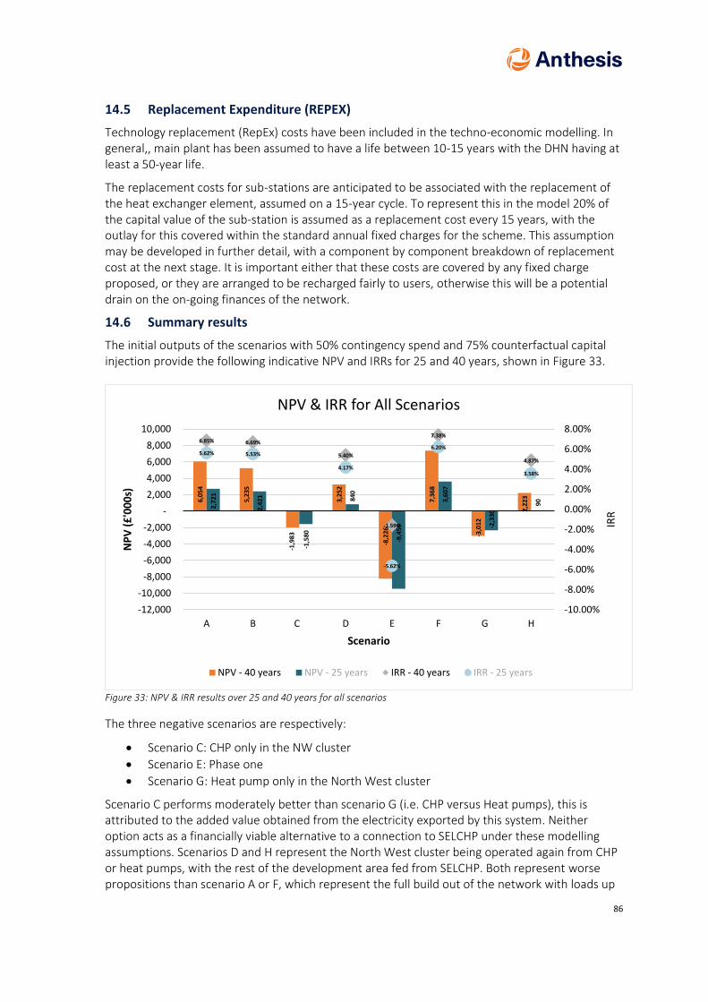
86
14.5 Replacement Expenditure (REPEX)
Technology replacement (RepEx) costs have been included in the techno-economic modelling. In general,, main plant has been assumed to have a life between 10-15 years with the DHN having at least a 50-year life.
The replacement costs for sub-stations are anticipated to be associated with the replacement of the heat exchanger element, assumed on a 15-year cycle. To represent this in the model 20% of the capital value of the sub-station is assumed as a replacement cost every 15 years, with the outlay for this covered within the standard annual fixed charges for the scheme. This assumption may be developed in further detail, with a component by component breakdown of replacement cost at the next stage. It is important either that these costs are covered by any fixed charge proposed, or they are arranged to be recharged fairly to users, otherwise this will be a potential drain on the on-going finances of the network.
14.6 Summary results
The initial outputs of the scenarios with 50% contingency spend and 75% counterfactual capital injection provide the following indicative NPV and IRRs for 25 and 40 years, shown in Figure 33.
Figure 33: NPV & IRR results over 25 and 40 years for all scenarios
The three negative scenarios are respectively:
• Scenario C: CHP only in the NW cluster
• Scenario E: Phase one
• Scenario G: Heat pump only in the North West cluster
Scenario C performs moderately better than scenario G (i.e. CHP versus Heat pumps), this is attributed to the added value obtained from the electricity exported by this system. Neither option acts as a financially viable alternative to a connection to SELCHP under these modelling assumptions. Scenarios D and H represent the North West cluster being operated again from CHP or heat pumps, with the rest of the development area fed from SELCHP. Both represent worse propositions than scenario A or F, which represent the full build out of the network with loads up
6,0
54
5,2
35
-1,9
83
3,2
52
-8,2
26
7,3
68
-3,0
12
2,2
23
2,7
21
2,4
21
-1,5
80
840
-9,4
59
3,6
07
-2,3
30
90
6.85% 6.69%
5.40%
-1.59%
7.38%
4.87%
5.62% 5.53%
4.17%
-5.62%
6.20%
3.58%
-10.00%
-8.00%
-6.00%
-4.00%
-2.00%
0.00%
2.00%
4.00%
6.00%
8.00%
A B C D E F G H
-12,000
-10,000
-8,000
-6,000
-4,000
-2,000
-
2,000
4,000
6,000
8,000
10,000
IRR
Scenario
NP
V (
£'0
00
s)
NPV & IRR for All Scenarios
NPV - 40 years NPV - 25 years IRR - 40 years IRR - 25 years
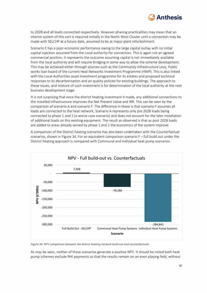
87
to 2028 and all loads connected respectively. However phasing practicalities may mean that an interim system of this sort is required initially in the North West Cluster until a connection may be made with SELCHP at a future date, assumed to be at major plant refurbishment.
Scenario E has a poor economic performance owing to the large capital outlay with no initial capital injection assumed from the Local authority for connection. This is again not an agreed commercial position, it represents the outcome assuming capital is not immediately available from the local authority and will require bridging in some way to allow the scheme development. This may be achieved either through sources such as the Community Infrastructure Levy, Public works loan board of the current Heat Networks Investment Programme (HNIP). This is also linked with the Local Authorities asset investment programme for its estates and proposed technical responses to its decarbonisation and air quality policies for existing buildings. The approach to these issues, and mixture of such investment is for determination of the local authority at the next business development stage.
It is not surprising that once the district heating investment it made, any additional connections to the installed infrastructure improves the Net Present Value and IRR. This can be seen by the comparison of scenario A and scenario F. The difference in these is that scenario F assumes all loads are connected to the heat network, Scenario A represents only pre 2028 loads being connected to phase 1 and 2 (a worse case scenario) and does not account for the later installation of additional loads on this existing equipment. The result as observed is that as post 2028 loads are added to areas already served by phase 1 and 2 the economics of the system improve.
A comparison of the District heating scenarios has also been undertaken with the Counterfactual scenarios, shown in Figure 34. For an equivalent comparison scenario F – full build out under the District heating approach is compared with Communal and individual heat pump scenarios.
Figure 34: NPV comparison between the district heating network build out and counterfactuals
As may be seen, neither of these scenarios generate a positive NPV. It should be noted both heat pump schemes exclude RHI payments so that the results remain on an even playing field, without
7,368
-78,286
-284,841
Full Build Out - SELCHP Communal Heat Pump Systems Individual Heat Pump Systems
-300,000
-250,000
-200,000
-150,000
-100,000
-50,000
-
50,000
Scenario
NP
V (
£'0
00
s)
NPV - Full build-out vs. Counterfactuals
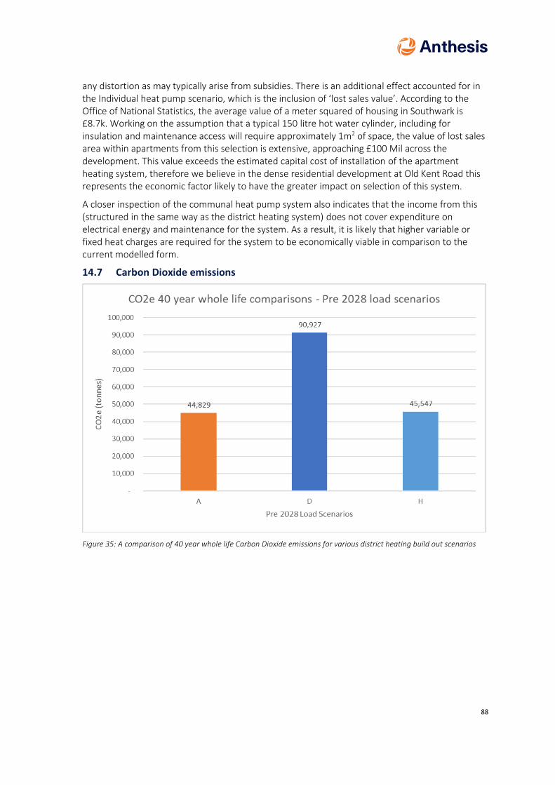
88
any distortion as may typically arise from subsidies. There is an additional effect accounted for in the Individual heat pump scenario, which is the inclusion of ‘lost sales value’. According to the Office of National Statistics, the average value of a meter squared of housing in Southwark is £8.7k. Working on the assumption that a typical 150 litre hot water cylinder, including for insulation and maintenance access will require approximately 1m2 of space, the value of lost sales area within apartments from this selection is extensive, approaching £100 Mil across the development. This value exceeds the estimated capital cost of installation of the apartment heating system, therefore we believe in the dense residential development at Old Kent Road this represents the economic factor likely to have the greater impact on selection of this system.
A closer inspection of the communal heat pump system also indicates that the income from this (structured in the same way as the district heating system) does not cover expenditure on electrical energy and maintenance for the system. As a result, it is likely that higher variable or fixed heat charges are required for the system to be economically viable in comparison to the current modelled form.
14.7 Carbon Dioxide emissions
Figure 35: A comparison of 40 year whole life Carbon Dioxide emissions for various district heating build out scenarios

89
Table 15: Summary of carbon factors for various energy sources
Carbon Factor 2019/20 2035 Source
Electricity 0.291 0.066 UK Treasury Green Book – Supplementary guidance – valuation of Energy Use and Greenhous gas - April 2009. Long term marginal generation-based carbon factor
Natural Gas 0.184 0.184 DEFRA 2018/19
Heat from EfW 0.046 g/kWh Thermal*
0.011 g/kWh Thermal*
BSRIA Rules of thumb (2011) Deprecated by the UK Treasury Green Book – Supplementary guidance – valuation of Energy Use and Greenhous gas - April 2009. Long term marginal generation-based carbon factor
*Awaiting Plant Specific update for SELCHP, compliant with SAP Appendix C
Scenarios A , D and H all have comparable thermal loads which are the full build out across Old Kent Road plus existing loads for Southwark. The differences are related to the technological treatment of the North West zone. For Scenario A, this is included with all the other loads and served from SELCHP. For Scenario D the North West zone is served by a stand-alone CHP system, and in Scenario H a stand-alone Heat pump system, with all other loads served by SELCHP. The Thermal loads assumed on Phase 1 and Phase 2 are only the ‘pre 2028’ loads, a limitation of the scenario selection in Section 10. This has no bearing on the carbon analysis though, as the relative differentiation between the 3 scenarios will be the same.
The results for a 40 year whole life carbon emission scenario is presented in Figure 35. This includes accounting for a reduction in carbon factors over time as estimated in Table 15 to reflect a decarbonisation of the National Grid. The SELCHP supply in scenario A produces the lowest whole life emissions. These emissions arise from the loss of electrical efficiency at the steam turbine owing to the heat take off. The large increase in emissions observed in scenario D arises from the additional gas consumed to generate electricity in the CHP included in the North West plot under this scenario. This is a little larger than the emissions for the rest of the build out, fed from SELCHP. These arise from the greater consumption of gas in the CHP engine to produce the electricity which in turn generates the income supporting the business case for the scheme.
Lower carbon emissions may be observed for scenario H in comparison to D, where a communal heat pump system is proposed to serve the North West Plot. This is clearly a lower carbon alternative to the CHP system modelled in D. The total net emissions however are higher than the SELCHP only approach, though it appears only be a marginal amount.
The emissions for the heat pump counterfactuals are highly dependent on the carbon factor of electricity in the medium to long run, which itself has a number of dependencies. There is both a
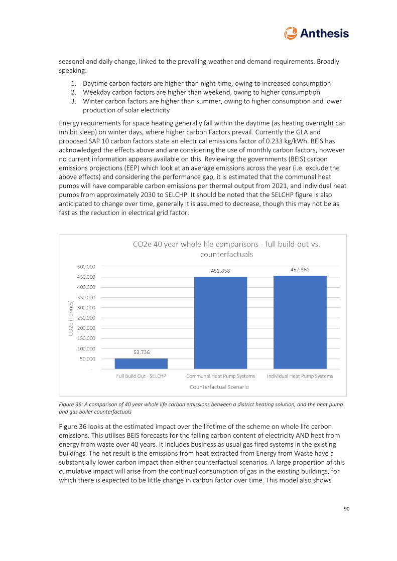
90
seasonal and daily change, linked to the prevailing weather and demand requirements. Broadly speaking:
1. Daytime carbon factors are higher than night-time, owing to increased consumption 2. Weekday carbon factors are higher than weekend, owing to higher consumption 3. Winter carbon factors are higher than summer, owing to higher consumption and lower
production of solar electricity
Energy requirements for space heating generally fall within the daytime (as heating overnight can inhibit sleep) on winter days, where higher carbon Factors prevail. Currently the GLA and proposed SAP 10 carbon factors state an electrical emissions factor of 0.233 kg/kWh. BEIS has acknowledged the effects above and are considering the use of monthly carbon factors, however no current information appears available on this. Reviewing the governments (BEIS) carbon emissions projections (EEP) which look at an average emissions across the year (i.e. exclude the above effects) and considering the performance gap, it is estimated that the communal heat pumps will have comparable carbon emissions per thermal output from 2021, and individual heat pumps from approximately 2030 to SELCHP. It should be noted that the SELCHP figure is also anticipated to change over time, generally it is assumed to decrease, though this may not be as fast as the reduction in electrical grid factor.
Figure 36: A comparison of 40 year whole life carbon emissions between a district heating solution, and the heat pump and gas boiler counterfactuals
Figure 36 looks at the estimated impact over the lifetime of the scheme on whole life carbon emissions. This utilises BEIS forecasts for the falling carbon content of electricity AND heat from energy from waste over 40 years. It includes business as usual gas fired systems in the existing buildings. The net result is the emissions from heat extracted from Energy from Waste have a substantially lower carbon impact than either counterfactual scenarios. A large proportion of this cumulative impact will arise from the continual consumption of gas in the existing buildings, for which there is expected to be little change in carbon factor over time. This model also shows

91
individual heat pumps having higher carbon emissions than communal heat pumps despite the distribution losses, owing to the lower in use efficiency of these systems.
Government models1 demonstrate that Energy from Waste (EfW) has a lower carbon impact than landfill, and that key to improving carbon performance of these systems is making better use of the reclaimed energy, particularly heat. Recovering heat reduces the efficiency of electrical production at the facility, therefore consideration is required of the relative merits of energy usage, as electricity is normally considered more valuable or a ‘higher grade’ of energy than heat. The ratio of electricity lost to heat produced is known as the z-factor in this equipment. Veolia has declared their long run z-factor is of the magnitude 6.7, i.e. for each 6.7 units of heat drawn from the system, 1 unit of electricity is lost. This is analogous to the reverse in heat pumps, Coefficient of performance (COP) which is the number of units of heat produced from one unit of electricity used. In our models we have used a COP of 2.3 for communal heat pumps, and 1.7 for individual heat pumps, weather adjusted to reflect benefits from warmer air. These would need to nearly triple to match the performance (in heat production) of SELCHP, which is considered unlikely. This comparison does not include for the carbon associated with heat losses in the wider district network, but the modelled assumptions of 10% (network) and 15% (risers) are linked to best practice standards and accounted for in the modelling. These would need to be substantially worse to increase carbon performance to the levels associated with the heat pump. This is considered an unrealistic scenario, however we would stress the need for connecting parties and the network developer to focus on thermal losses, not only to ensure good system carbon performance, but to facilitate good thermal comfort, prevent localized overheating issues and reduce operating costs and fuel poverty impacts.
This is however dependent on the real carbon emissions for heat achieved from the incinerator. This in turn is impacted by the decarbonisation of electricity, as well as the ‘fossil fuel’ content of the waste incinerated. Therefore, future values of CO2 from incinerators are dependant on the interaction of 2 factors, making forecasting even more complex. If fossil fuel-based waste is eliminated it is generally considered any remaining carbon is ‘short cycle’ therefore has net zero impact overall. However if the grid decarbonises faster than the waste stream, the value of the carbon offset from fossil fuel equivalent power stations decreases and emissions factors can rise relative to other system at the incinerator. Appendix C of the SAP provides the government mandated way to assess final emissions for heat under current building regulation, and we await confirmation from SELCHP as to where this currently lies. For the purposes of this report alternative referenceable deprecating factors have been assumed as laid out in table 15.
A simpler way to consider this may be though consideration of cumulative carbon locally. The SELCHP facility already exists and is a key part of local waste management. The carbon produced from this (which as discussed, for various reasons can be complex to model) is already produced to atmosphere, with excess heat energy also dissipated to atmosphere. By extracting waste heat from the facility and making use of it locally no net additional carbon will enter the atmosphere, with a substantial portion of the local area heat demand satisfied. In the counterfactuals, all energy required to operate this equipment, does not exist, and will need to be created (at assumed carbon factors). Therefore, this carbon is all additive to the environment.
1 Energy recovery for residual waste – A carbon based modelling approach, February 2014, DEFRA
92
14.8 NOx
A similar argument simplifies the NOx analysis between systems. The local area is already impacted by any NOx produced from the incinerator. This is centrally treated to be minimised, released at a high level to maximise dispersion and closely monitored for compliance against environmental criteria. Non-compliance may be quickly identified and rectified. Additional treatment requires the installation of equipment at just one location. Utilising heat locally means that no net additional NOx emissions are produced locally to the detriment of local air quality (unlike for example, gas boilers). Furthermore, the diffuse nature of traditional gas boilers, with exhaust close to ground level makes them harder to monitor compliance against, and more likely to have an immediate impact to ground level air quality. These issues are avoided through connection to SELCHP, and in particular there is a direct reduction in local NOx emissions that would have been produced locally in the existing buildings.
As an approximation of the quantity of NOx produced by SELCHP, this has been estimated as 350 mg/kWh heat exported. Emissions at the SELCHP stack average at 180 mg/Nm3 of exhaust gas, it should be noted this is a different metric from the ‘kWh’ figure, with the emissions per unit of electrical or thermal output varying according to how they are allocated to these varying outputs. At this rate, the emissions of NOx associated with the new thermal output for the district heating scheme would be 29.5 tonnes, however this would be accompanied by an equivalent reduction in NOx attributed to SELCHP’s electrical production. Additionally, it is forecast that NOx emissions at SELCHP will reduce in 2024 owing to an upgrade to the DeNOx exhaust treatment system on site, underway in response to other legislation changes. This is forecast to reduce the daily emissions cap from 200 mg.Nm3 to 180 mg.Nm3 with a corresponding reduction in the average emissions factor.
Even in a comparison to the Heat pump counterfactual, where local NOx emissions are eliminated, there is an additive energy demand (i.e. existing wasted energy is not captured). This electrical energy also has a NOx component arising from the combustion processes in the generation mix, therefore an increased energy demand also means an increase in national NOx emissions, to the detriment of air quality. Once again, connection to SELCHP results in no net impact to NOx, as use would be made of previously wasted heat.
14.9 Refrigerants
Anthesis’s strategy has not extended to the Carbon Dioxide equivalent of Refrigerants utilise in the counterfactual. Historic refrigerants have had very high (sometimes in excess of 3000) global warming potential, with leakage a common occurrence. As a result, measurable quantities of industrial refrigerant gas in the atmosphere now make a meaningful contribution to climate change. Refrigerant regulation (F-gas) has been amended recently to reflect this and is leading to a large change in equipment design and refrigerant selection. This makes it difficult for Anthesis to quantify the carbon impact of future refrigerant equipment. Additionally, some new or alternative refrigerants have additional risk in usage in comparison to historic refrigerants, for example:
• Increased flammability
• Explosive risk
• Toxicity, in a natural state, or upon combustion

93
As a result, it is recommended, that on a case by case basis, where heat pumps are proposed at any level (i.e. individual or communal), the council requests additional information from a developer:
• Details of the Global Warming equivalent emissions from refrigerant, over the equipment lifetime (i.e. accounting for leakage)
• Details of how leakage risk is proposed to be mitigated
• Details of additional risks from refrigerant selection (e.g. fire, explosion etc) and how these risks are proposed to be mitigated in design
• Where a refrigerant with a foreseeable phase out date is proposed (e.g. R410, R32) a replacement strategy is provided for the equipment’s end of life, accounting for its removal, degassing, and any foreseeable alternative replacement
The aim of the last point in particular, is to avoid the construction of a plant facility or heating strategy which is dependent on one particular refrigerant, which may be unavailable within the building lifetime. For example, a commercial system designed with a large traditional R410 VRF gas-based refrigeration system may not be able to use an equivalent system in the future owing to limited equipment selection arising from regulatory change. In this circumstance, the developer should describe how they have considered how an alternative future technical solution would be installed, and what the limitations are on its installation at this time.
The purpose of this section is not to overstate the risk of using this equipment, nor to approve or disapprove of its usage. Heat pumps are likely to form a key part of an energy strategy at this scale. The above recommendations are to bring transparency to the whole life environmental impact of such selection, and provide some signposts for the local authority and developer or landlord as to other implications of their usage so they may be sensibly managed at early stages of design.
15 Sensitivity and Risk
The sensitivity of one SELCHP scenario was tested, as shown in Figure 37, representing full build out across the Old Kent Road opportunity area (Scenario F).
The sensitivity tests undertaken are derived from HNDU guidance, as typically used to test business opportunities in the district heating market.
These outputs show that the scheme is sensitive to:
• Changes in Capital cost- both direct costs, and those offset by grants or their equivalent
• Energy sales (heat) tariffs
As may be seen, the system has less sensitivity to changes in gas prices and electrical prices, as the heat supply is not directly linked to these markets, and the Fuel source is Waste in various forms. Therefore, the scheme economic viability is largely dependent on the capital cost of the scheme, as well as the price charged for the heat supply.
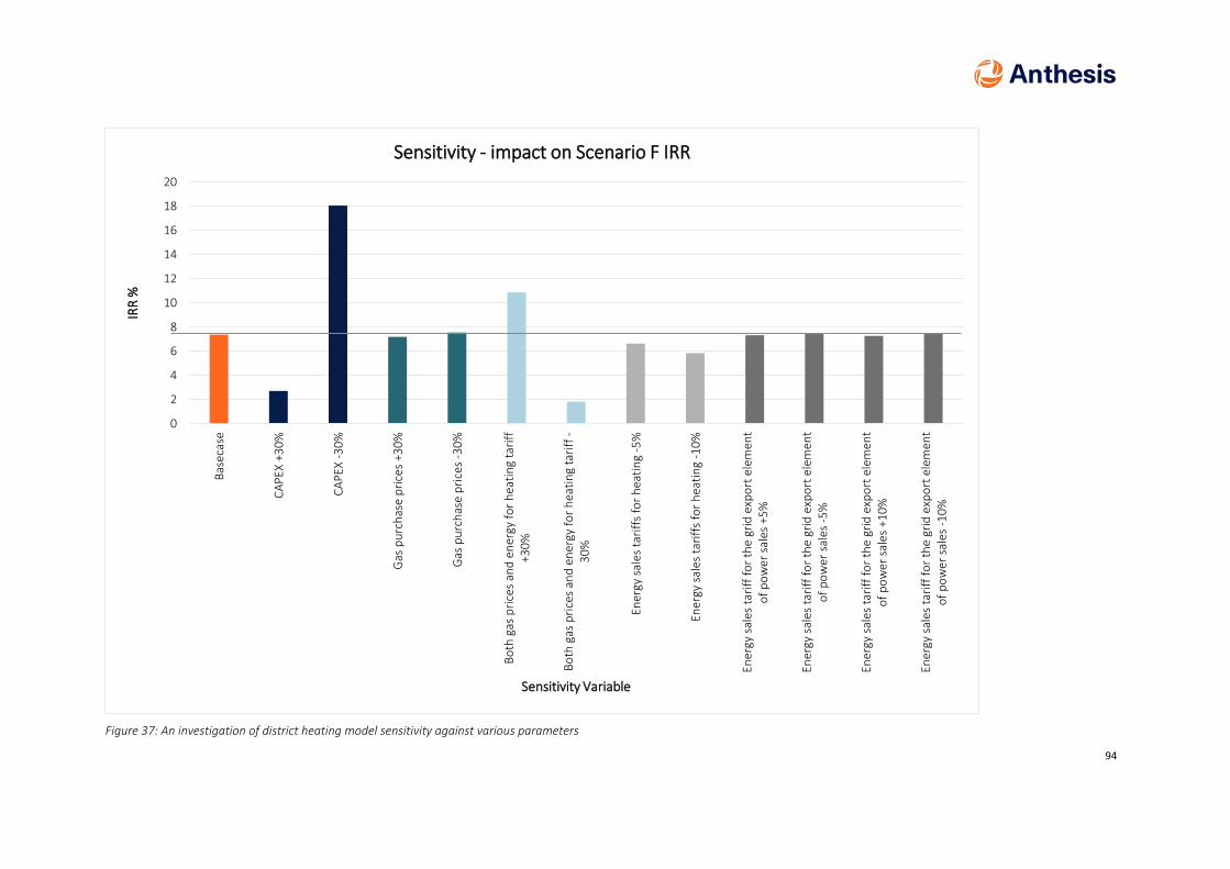
94
Figure 37: An investigation of district heating model sensitivity against various parameters
0
2
4
6
8
10
12
14
16
18
20
Bas
ecas
e
CA
PEX
+3
0%
CA
PEX
-3
0%
Gas
pu
rch
ase
pri
ces
+30
%
Gas
pu
rch
ase
pri
ces
-30
%
Bo
th g
as p
rice
s an
d e
ner
gy f
or
hea
tin
g ta
riff
+30
%
Bo
th g
as p
rice
s an
d e
ner
gy f
or
hea
tin
g ta
riff
-3
0%
Ener
gy s
ales
tar
iffs
fo
r h
eati
ng
-5%
Ener
gy s
ales
tar
iffs
fo
r h
eati
ng
-10
%
Ener
gy s
ales
tar
iff
for
the
grid
exp
ort
ele
men
to
f p
ow
er s
ales
+5
%
Ener
gy s
ales
tar
iff
for
the
grid
exp
ort
ele
men
to
f p
ow
er s
ales
-5
%
Ener
gy s
ales
tar
iff
for
the
grid
exp
ort
ele
men
to
f p
ow
er s
ales
+1
0%
Ener
gy s
ales
tar
iff
for
the
grid
exp
ort
ele
men
to
f p
ow
er s
ales
-1
0%
IRR
%
Sensitivity Variable
Sensitivity - impact on Scenario F IRR
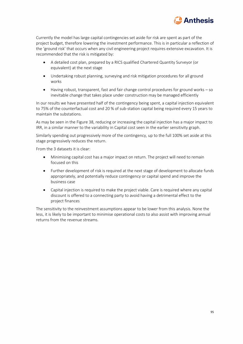
95
Currently the model has large capital contingencies set aside for risk are spent as part of the project budget, therefore lowering the investment performance. This is in particular a reflection of the ‘ground risk’ that occurs when any civil engineering project requires extensive excavation. It is recommended that the risk is mitigated by:
• A detailed cost plan, prepared by a RICS qualified Chartered Quantity Surveyor (or equivalent) at the next stage
• Undertaking robust planning, surveying and risk mitigation procedures for all ground works
• Having robust, transparent, fast and fair change control procedures for ground works – so inevitable change that takes place under construction may be managed efficiently
In our results we have presented half of the contingency being spent, a capital injection equivalent to 75% of the counterfactual cost and 20 % of sub-station capital being required every 15 years to maintain the substations.
As may be seen in the Figure 38, reducing or increasing the capital injection has a major impact to IRR, in a similar manner to the variability in Capital cost seen in the earlier sensitivity graph.
Similarly spending out progressively more of the contingency, up to the full 100% set aside at this stage progressively reduces the return.
From the 3 datasets it is clear:
• Minimising capital cost has a major impact on return. The project will need to remain focused on this
• Further development of risk is required at the next stage of development to allocate funds appropriately, and potentially reduce contingency or capital spend and improve the business case
• Capital injection is required to make the project viable. Care is required where any capital discount is offered to a connecting party to avoid having a detrimental effect to the project finances
The sensitivity to the reinvestment assumptions appear to be lower from this analysis. None the less, it is likely to be important to minimise operational costs to also assist with improving annual returns from the revenue streams.
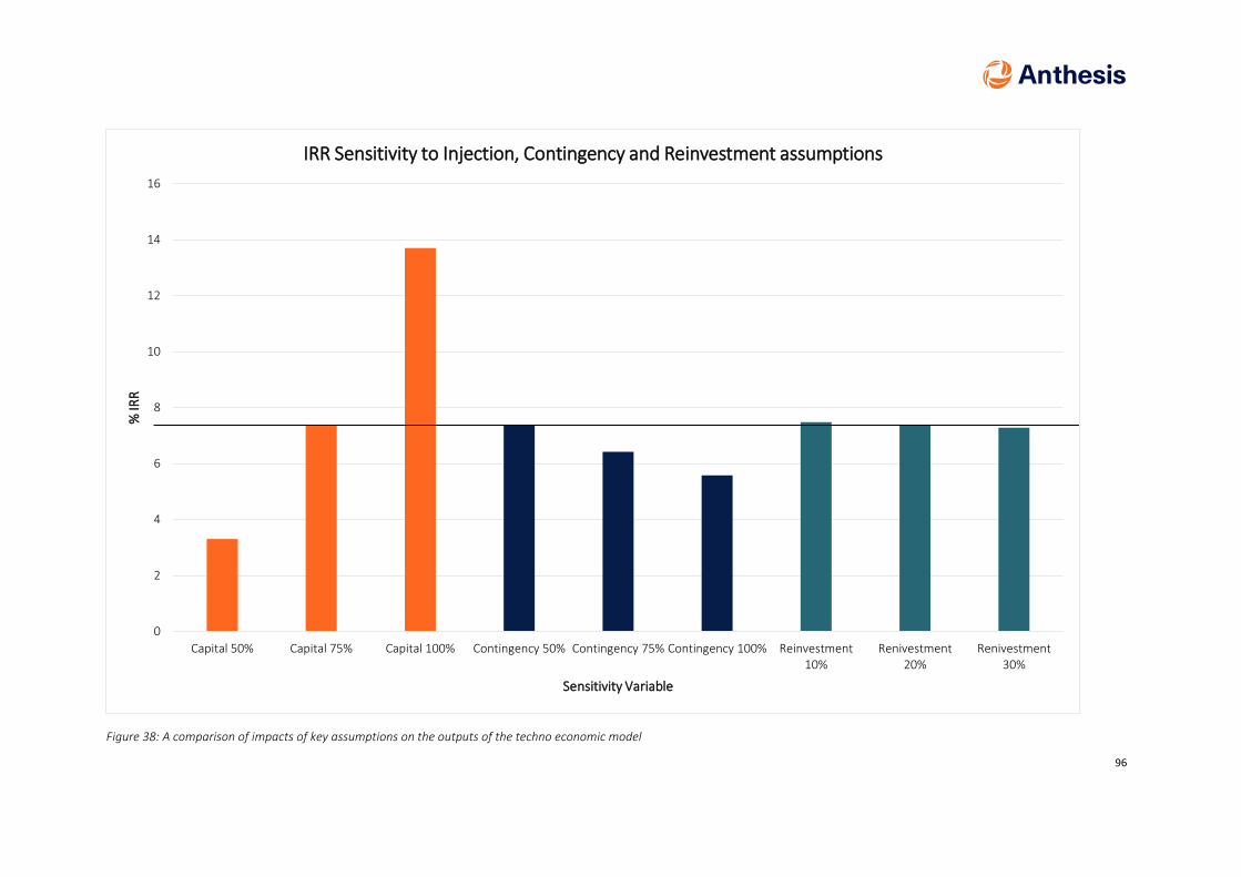
96
Figure 38: A comparison of impacts of key assumptions on the outputs of the techno economic model
0
2
4
6
8
10
12
14
16
Capital 50% Capital 75% Capital 100% Contingency 50% Contingency 75% Contingency 100% Reinvestment10%
Renivestment20%
Renivestment30%
% IR
R
Sensitivity Variable
IRR Sensitivity to Injection, Contingency and Reinvestment assumptions

97
The heat network appears to have a classic ‘large infrastructure’ type business case, with construction risk upfront, but any potential returns at a constant low rate over a long period of time. We would therefore recommend that a detailed business case is produced at the next stage, and continually updated through construction to become an accurate production model upon operation. Heat tariffs, both fixed and variable as well as connection charges will be required to be set to cover capital cost over the long term, cover operational costs and produce an acceptable return on the investment made. We would recommend to both users and potential network operators to focus on:
• Minimizing operation costs- e.g. through high quality automatic systems (metering, water quality monitoring, leak detection, control) etc
• Minimising demand at connections – through efficient secondary and tertiary (where required) system design with low losses, good control characteristics, as often characterized with low system return temperatures. This mitigates ‘demand risk’ to the council, through large variable heat payments or unnecessary heat consumption (i.e. losses). Similarly, the network operator should avoid financial returns being dependent on losses from poor quality connections, as resolution of these by connecting parties may have adverse effect on a business case. Minimising demand will also help reduce capital expenditure on installing any unnecessary excessive capacity within the network, one of the largest capital costs
• Minimising loss in the street network – to maximise carbon savings and reduce the variable cost of heat at connection
This will help mitigate the commercial risk for all parties on the project

98
16 Implementation plan and QA
A broad implementation plan has been proposed by the local authority. This envisages the agreement of the commercial and legal contract form for the initial Phase 1 parts of the extension by the middle of 2020. Assuming terms are agreed and contracts signed, it is envisaged that procurement and design will require a further two annual quarters, with construction commencing in 2021, and a year allowed for the initial build out.
Phase 2, and build out beyond this are likely to be determined by additional economic and planning agreements between Veolia and other development partners, and as previously highlighted, proceed on a ‘most economic’ basis.
To this end a rough development plan has been prepared and included in this document as an appendix. It is recommended that the project management at the next project stage detail out a programme for the procurement and tender processes. In parallel it would be best to prepare a construction programme (including any approval processes, e.g. Network Rail) with an appropriate contractor for example, as part of a negotiated tender process. The two combined programmes would give a best estimate of the duration of the project, as well as improving the accuracy of budget forecasts.
To ensure the quality of any developed scheme it is recommended that the CIBSE/ADE Code of practice for heat networks forms an ongoing basis for any contracts prepared, both between the Local Authority and any district heating supplier, and the district heating supplier and their construction contractors. This would include regular reviews and completion of the supporting checklists and materials supplied as part of this code. This report has been prepared in accordance with the principles and values of the current Code, however there remain some limitations in the assessment owing to the nature of the appointment. For example the Code requires inputs from the District Heating ‘Client’, when this commission arises from the local authority supported by the regional authority (GLA). As such no direct ‘client’ operating district heating is available, though the authors do acknowledge the support and information supplied by Veolia operators of SELCHP to date to inform this study. Therefore, whereas our work follows the Code where this has been possible, and quotes its design standards in for example Section 9.4 (Energy Interface within development blocks) we would recommend this is revisited and updated as part of the commercial negotiation works between the Local Authority and proposed district heating operator at the next stage. The authors of this report are also aware of an impending update to the Code of practice, and it would be reasonable to assume when this is published and made public, this should supersede the current document, assuming no statutory conflicts or equivalent. Future legal agreements should consider this and where possible reflect the anticipated change to the guidance, with an appropriate balance of risk and cost between the parties involved.
Equally important will be to protect the consumer and end user on the network, particularly any vulnerable or fuel poor tenants which reside within the Local Authority premises. The Competition and Markets Authority has recommended that heat networks become regulated in the future owing to the risk that they could abuse their position as a natural monopoly in certain geographic locations. However details of these regulations have not yet been published and an interim solution is likely to be required. The Code of practice references the Heat Trust (https://heattrust.org/) as an existing alternative voluntary scheme providing guidance on minimum standards, and we recommend that this is followed as an interim solution. This includes minimum standards of service and protection mechanisms for vulnerable customers. It has also been indicted by Veolia, operators of SELCHP that this would be a standard they would operate to, and already have experience operating at for other heat networks. This should be confirmed,

99
again with adherence forming part of the agreed contracts between customer (i.e. London Borough of Southwark), Operator (Assumed Veolia) and build out contractor.
In these manners it is anticipated the quality of the scheme and construction and during operation may be agreed and enforced to the satisfaction of all parties.
100
17 Application for funding
The Government is committed to developing a self-sustaining heat networks market in the UK that can operate in the long-term without direct Government subsidy. The Department for Business, Energy and Industrial Strategy (BEIS) has launched the Heat Networks Investment project (HNIP) - a major Government project which will invest up to £320m of capital funding in heat network projects. HNIP will ensure that the schemes of the highest quality – delivering both carbon savings and consumer benefits – will be incentivised to apply for HNIP funding. HNIP funds are specifically offered as ‘gap funding’ through a combination of grants and loans and have been offered to eligible projects since April 2019. The scheme will be open for applications for a period of up to three years
Triple Point Heat Networks Investment Management (TP Heat Networks) has been appointed by the Department for Business, Energy & Industrial Strategy (BEIS) as its Delivery Partner for
the HNIP scheme.
Key areas applicants should be focussed on include the application process itself and how this will function. TP Heat Networks has set up a two-stage application process, first a pre-application to ensure projects applying for funding meet the HNIP eligibility criteria and then secondly the full application. Only successful pre-application projects will be eligible to submit a full application. Experienced Business Development Managers are available to support applicants prior to and during the pre-application stages of the application process
Applicants are responsible for their own compliance with State Aid rules. As a result, applicants must ensure they have sought their own professional advice in relation to State Aid as part of submitting a pre and full HNIP application.
Applications will be awarded funding on a competitive basis to maximise value for money. As such even if an application meets all the eligibility criteria and scores well, there is no guarantee of a funding award. This process is governed by the ‘Investment Mandate’, a statement of aims and investment policy, including without limitation, any applicable limits on investment that may be made by the HNIP Investment Committee.
Initial review, combined with investigatory conversations, leads us to believe that the Old Kent Road project can deliver on most of the eligibility criteria.
In particular the first phase of the works (Scenario E) represents a large speculative capital expenditure by a party, with a low IRR, which is not equivalent to the cost of capital. Returns to the project only materialise once the infrastructure is more fully utilised by further build out on the scheme (see alternative scenarios, e.g. A and F). When reviewing the MIRR, the returns for the project improve in the long term (40 years) but still do not increase above the cost of capital. In addition, the TEM is currently produced using real current prices, therefore does not account for price inflation. This typically results in a further deduction from the rate of return. As discussed in this report, the rate of return may be improved by adjusting charges for heat assuming these do not increase beyond a viable economic alternative, often chosen as the price of gas. This is a commercial decision, however contained within this choice is a decision regarding the sources of Capital. The HNIP project is orientated around activating projects by funding them favourably so that they achieve minimum economic measures (e.g. Rates of return) at the outset, to facilitate the long term growth seen in later scenarios where the projects appear more viable. The selection of funding sources and rates is likely to therefore influence the final heat price. By pursuing HNIP funding, the local authority or Veolia may be able to facilitate a lower heat price for current and existing residents, as well as provide a key piece of green infrastructure within the borough with

101
value over the long term, as well as adding value for the redevelopment of the Old Kent Road are. However, further work is needed to ascertain the final scope of the scheme, reduce risk further, re-assess capital cost and proposed funding sources, to move the scheme to a pre-application stage.

102
18 Recommendations and next steps
Over the last year Anthesis have comprehensively reviewed opportunities for the future energy supply of the Old Kent Road opportunity area. This has included an expansion of the initial scope and brief to better understand the commercial case, and key role to be played by the local authority in facilitating this strategy. Other developments in this timeframe have included changes to phasing, carbon factors and policy, all of which have impacted on our findings and proposed strategy.
The following summarises the recommendations of our work, considering our conclusions and points of interest raised in the preceding sections.
18.1 Connection to SELCHP
We believe a key opportunity exists to connect the redevelopment in the Old Kent Road Area to the local SELCHP facility, which has the potential to provide a stable, low cost, low carbon heating solution, with minimal net impact on air quality in the area for all development.
In making this recommendation we have also highlighted some key issues in facilitating this. The infrastructure installation from SELCHP to the opportunity are is not straight forward, with a number of key technical infrastructure hurdles to cross, including railways and large underground utility assets. We believe it is unlikely that any single development in the redevelopment area can facilitate the first connection to SELCHP. However, we have identified a practicable way forward to achieve this. We describe this as ‘Phase 1’ of a proposed district heating installation, serving a number of large existing council thermal loads in the local area. Serving these loads from SELCHP would at a single stroke, significantly reduce the carbon emissions of these estates as well as reduce local combustion emissions, assisting in improving air quality within the borough. It is highlighted that improvements are required to heating and heat distribution systems at these council locations, and that these are beyond the scope of this report. Improving the secondary system is likely to lead to improvements for thermal comfort for residents, as well as reducing operational costs, and potentially capital costs for an installed district heating system.
The installation of phase 1 provides the key distribution route to the Old Kent Road opportunity area. A second phase continues the installation to the western end of this, where development is anticipated to occur in the first instance. Completion of the two phases allows an organic expansion of the network, from the core distribution areas into the development zone in the most economic manner possible considering the dynamic and changing nature of development in the area.
With the existence of SELCHP nearby there is effectively a straight comparison to be had between the installation of a heat network and the installation of additional electrical equipment to serve alternative electrical based heating strategies (as well as future transportation requirements). It is our understanding, based on the methodologies and calculations detailed within this report that connection to SELCHP offers the lowest whole life cost route to achieving current policy objectives.
A key risk to this approach is the necessity for the council and SELCHP facility operator (combined with any potential 3rd party network installer) to agree a commercial case which will allow the installation of phase 1.

103
Benefits
• Low carbon heating for existing and new housing in the Old Kent road
• The basis of a large District Heating network for existing and new build development in the future across this region of London
• Negligible air quality impact arising from new development, and a reduction in local emissions for existing housing
• Further mitigation to environmental impact of local incinerator into the future
Key Risk
• Requires initial commercial agreement to install phase 1 of the network between SELCHP, any potential network operator and the local authority.
18.2 Other Practicalities
Away from the North, West and South development plots there is a North West area of development. We believe that it will be practically difficult to serve this, particularly aspects anticipated to be delivered in 2022 from SELCHP at the initial development phases. It is therefore recommended that a separate, standalone system or systems is developed at this location. It is recommended these utilise water based thermal distribution systems (either conventional, or ambient loop) which are compatible with interconnection in the future with a wider SELCHP system. This will facilitate future connection assuming there is an economic case for this at a later date. There is a case for these systems to be served either by heat pumps, or conventional gas boiler and CHP systems (with appropriate equipment to mitigate air quality impact), with a better carbon case for the former, and a better economic case for the latter.
Benefits
• Decouples the North West Plot from other development, and the installation of a district heating system fed from SELCHP
Key risk
• Interconnection with SELCHP dependent on future economic case, therefore limiting potential environmental benefits in this development area
18.3 Other Solutions
Additional solutions exist over and above those recommended above, to meet the energy needs of the development area, and we do not believe these should be stifled by a single approach. Other opportunities may exist for utilizing waste heat in this area. The major foreseeable opportunity would be the extension of the Bakerloo line. This would result in two station boxes, where an integrated approach to heating and cooling strategy for the infrastructure and any co-development (retail, housing etc), including making use of the ground (where appropriate) may well be preferable and feasible on environmental grounds. We do not believe this will be sufficient to meet the wider need of the development area, but where locally achievable it should be encouraged assuming an alternative economic case exists for installation. Any system installed should retain a wet energy thermal distribution system of some form to protect future potential integration with SELCHP. It is possible to envisage other similar system, not yet proposed as part of the initial stages of development. For example, were a datacenter or chilled distribution warehouse be proposed on a development plot, the same opportunity would exist (spare waste heat from refrigeration) and once again this concept would be valid.

104
Failing the installation of the initial phase 1 of a district heating system from SELCHP, we would assume that communal heat pump systems from air source would be the predominant system. We believe a key driver to this would be the additional potential sales area released within apartments in comparison with an individual heat pump approach.
Individual heat pumps are also not discounted for small development areas. It is foreseeable that some development plots may have certain uses, e.g. small commercial units where this is the preferable building service solution, though it is not anticipated to be the norm. Where such installations take place, it is recommended that planners are mindful of the environmental impacts of the proposed refrigerant, the potential risks associated with these, and the future maintenance and replacement strategy of the equipment considering the foreseeable phase out of existing refrigerant gases.
Photovoltaics are also considered to be a likely key electrical energy source that will be deployed across the development area. Although it is unlikely these will meet the full quantum of electrical energy requirements, particularly across the high-density development areas, they will displace remotely generated electricity with a carbon content, for local carbon and NOx free electricity. For this reason, it is anticipated they will be continued to be encourages to be installed where appropriate across developments as part of an overall carbon strategy. It has been highlighted that current electrical infrastructure planning has not accounted for this foreseeable distributed renewable generation across the development area, nor the potential impact of increased electrical demand from electrical vehicles (private or fleet), and it is recommended this is reviewed by the local authority in more detail.
Benefits:
• Alternative low carbon systems remain feasible, and are recommended to be deployed where these are financially and technically viable, and suitable for the local planning context
Key Risk:
• Electrical infrastructure planning does not currently appear to consider foreseeable demands, e.g. the electrification of transportation, nor the impact of further distributed generation (e.g. PV) across the development area
18.4 Heat Network Investment Project application
It is recommended that the project team investigate the potential of BEIS HNIP funding and reflect on how this may impact the commercial development of the project. Further work is needed to advance to the pre-application stage.
18.5 Final Conclusions and next steps
Our analysis has shown that a key opportunity exists at Old Kent Road to make best use of an existing nearby infrastructure asset, and in doing so facilitate low carbon local development with low impacts on air quality in the local area. This is not to exclude other renewable heating systems in the area, where appropriate for the planning context, for example in the North West Development plot, or where identifiable sources of waste heat exist.
The key next step to move forward the recommendations is the development of a detailed commercial model of development and deployment of the initial District Heating phases. The critical stakeholder for this will be the local authority, as without buy in for ‘Phase 1’ as described in this report it is high likely that widespread deployment of district heating in this area will not

105
take place, with negative environmental and financial impacts on new development in the area, as well as a lost opportunities for carbon reductions and air quality improvements to existing council building stock in the area.

106
Appendix A Policy review
A.1 Building Regulations, Part L
The latest edition of Part L of the Building Regulations is 2013, with further amendments occurring in 2016. District or block heating/cooling is mentioned within Regulation 25A (Consideration of high-efficiency alternative systems) and is included as a high-efficiency alternative system in both parts L1A (new dwellings) and L2A (new buildings other than dwellings). An analysis of technical, environmental and economic feasibility of implementing high-efficiency technologies must be carried out at design stage for new ventures, either individually or as a group, and notice must be provided to Building Control that this has happened. However, the regulations stress that they are technology neutral, therefore there is no requirement that a high-efficiency alternative system is installed.
A.2 Standard Assessment Procedure
The Standard Assessment Procedure (SAP) is the government-approved method for calculating the carbon emissions and energy efficiency of new dwellings to demonstrate compliance with Building Regulations and local planning policy. District heating is modelled by inputting details of the generation plant (boiler, CHP, heat pump etc.) and its efficiency, as well as a distribution loss factor which account for energy losses as a result of the existence and extent of distribution pipework, system temperature and control.
The Building Research Establishment are currently reviewing the SAP method, with significant changes proposed that could have a negative impact on how district heating contributes to low carbon and energy efficient design. This principally affects the amount of losses attributed to distribution systems that is applied to a dwelling, meaning more work will be needed to demonstrate that the system is working efficiently, or an increase in fabric measures or renewable technologies incorporated into the design.

107
A.3 Regional Policy
A.3.1 Current London Plan
https://www.london.gov.uk/sites/default/files/the_london_plan_2016_jan_2017_fix.pdf
The current London Plan was published in 2011, with the latest version – an update with minor alterations, published in March 2016.
Chapter five outlines London’s response to climate change, with the following policies of particular relevance to the installation of decentralised energy systems:
POLICY 5.2: MINIMISING CARBON DIOXIDE EMISSIONS
A: Development proposals should make the fullest contribution to minimising carbon dioxide emissions in accordance with the following energy hierarchy:
1. Be lean: use less energy
2. Be clean: supply energy efficiently
3. Be green: use renewable energy
B: The Mayor will work with boroughs and developers to ensure that major developments meet the following targets for carbon dioxide emissions reduction in buildings. These targets are expressed as minimum improvements over the Target Emission Rate (TER) outlined in the national Building Regulations leading to zero carbon residential buildings from 2016 and zero carbon non-domestic buildings from 2019.
Residential buildings:
Year Improvement on 2010 Building Regulations
2010 – 2013 25 per cent (Code for Sustainable Homes level 4)
2013 – 2016 40 per cent
2016 – 2031 Zero Carbon
Non-domestic buildings
Year Improvement on 2010 Building Regulations
2010 – 2013 25 per cent
2013 – 2016 40 per cent
2016 – 2019 As per building regulations requirements
2019 - 2031 Zero Carbon

108
It is noted that The Code for Sustainable Homes has now been withdrawn (aside from the management of legacy cases) and has been replaced by new national technical standards. However, under the previous guidance Level 4 is the equivalent of 25% lower carbon than Building Regulations Part L and level 5 is equivalent of 100% lower carbon under Building Regulations Part L.
However, the policy of lean/ clean/ green is still applicable and the approach for tacking energy supply.
POLICY 5.6 DECENTRALISED ENERGY IN DEVELOPMENT PROPOSALS
Planning decisions
A Development proposals should evaluate the feasibility of Combined Heat and Power (CHP) systems, and where a new CHP system is appropriate also examine opportunities to extend the system beyond the site boundary to adjacent sites.
B Major development proposals should select energy systems in accordance with the following hierarchy:
1) Connection to existing heating or cooling networks;
2) Site wide CHP network;
3) Communal heating and cooling;
C Potential opportunities to meet the first priority in this hierarchy are outlined in the London Heat Map tool. Where future network opportunities are identified, proposals should be designed to connect to these networks.
Policy 5.6 shows strong support for decentralised energy systems. A further consideration, in respect of the connection hierarchy above, would be the use of temporary heat plant where a network is planned but will not be operational until after the construction of a new development.
POLICY 7.14 IMPROVING AIR QUALITY
Planning decisions
B Development proposals should:
C be at least ‘air quality neutral’ and not lead to further deterioration of existing poor air quality (such as areas designated as Air Quality Management Areas (AQMAs)).
D ensure that where provision needs to be made to reduce emissions from a development, this is usually made on-site. Where it can be demonstrated that on-site provision is impractical or inappropriate, and that it is possible to put in place measures having clearly demonstrated equivalent air quality benefits, planning obligations or planning conditions should be used as appropriate to ensure this, whether on a scheme by scheme basis or through joint area based approaches
The Air quality standard required by this (Air Quality Neutral) is defined in the 2014 Sustainable Design and Construction Supplementary planning guidance (see section 2.4). This typically requires the use of low NOx CHP systems, with progressively tightening standards in poor air quality areas. The highest performing equipment typically requires Selective Catalytic Reduction (SCR) equipment

109
with an associated space take, CAPEX and OPEX cost. It is currently unclear how these standards may be updated to reflect the aspirations of the Draft New London Plan.
A.3.2 The Draft New London Plan
https://www.london.gov.uk/sites/default/files/new_london_plan_december_2017_web_version.pdf
Once adopted, the London Plan is a replacement to the previous versions issued in 2004 and 2011 and will supersede all previous content. Issued as draft for consultation in December 2017, the closing date for comments was 2nd March 2018 and it is expected to be published for ‘Examination in Public’ in Q4 2018. As such the content of the review may be subject to further amendment; however, the following is a review of the current content relevant to planning of a district energy scheme.
Of particular note, a significant emphasis has been placed on improving London air quality in the new plan:
POLICY SI1 IMPROVING AIR QUAITY
3) The development of large-scale redevelopment areas, such as Opportunity Areas and those subject to an Environmental Impact Assessment should propose methods of achieving an Air Quality Positive approach through the new development. All other developments should be at least Air Quality Neutral.
5) Air Quality Assessments (AQAs) should be submitted with all major developments, unless they can demonstrate that transport and building emissions will be less than the previous or existing use.
6) Development proposals should ensure that where emissions need to be reduced, this is done on-site. Where it can be demonstrated that on-site provision is impractical or inappropriate, off-site measures to improve local air quality may be acceptable, provided that equivalent air quality benefits can be demonstrated.
It is noted that, further guidance will be published on Air Quality Neutral and Air Quality Positive standards as well as guidance on how to reduce construction and demolition impacts. However, it is not clear when this will be available.
Policy SI2 Minimising greenhouse gas emissions
A Major development should be net zero-carbon. This means reducing carbon dioxide emissions from construction and operation, and minimising both annual and peak energy demand in accordance with the following energy hierarchy:
1) Be lean: use less energy and manage demand during construction and operation.
2) Be clean: exploit local energy resources (such as secondary heat) and supply energy efficiently and cleanly. Development in Heat Network Priority Areas should follow the heating hierarchy in Policy SI3 Energy infrastructure.
3) Be green: generate, store and use renewable energy on-site
In line with the “lean, clean and green” approach in previous London Plans, the energy hierarchy (London Plan Figure 9.2) should inform the design, construction and operation of new buildings – both domestic and non-domestic. The priority remains to minimise energy demand, and then address how energy will be supplied and renewable technologies incorporated.

110
POLICY SI2 MINIMISING GREENHOUSE GAS EMISSIONS
B) Major development should include a detailed energy strategy to demonstrate how the zero-carbon target will be met within the framework of the energy hierarchy and will be expected to monitor and report on energy performance. C) In meeting the zero-carbon target a minimum on-site reduction of at least 35 per cent beyond Building Regulations is expected. Residential development should aim to achieve 10 per cent, and non-residential development should aim to achieve 15 per cent through energy efficiency measures. Where it is clearly demonstrated that the zero-carbon target cannot be fully achieved on-site, any shortfall should be provided:
1) through a cash in lieu contribution to the relevant borough’s carbon offset fund, and/or 2) off-site provided that an alternative proposal is identified and delivery is certain.
In the new Plan, the zero carbon target (and subsequent requirement for off-setting payments) is for both domestic and non-domestic developments (currently this is only applied to residential developments). Although the price is regularly reviewed, the new plan advises a “nationally recognised non-traded price of £95/tonne” may be used by Boroughs; however, the charge levied is down to each individual borough.
It is noted a specific focus is on all developments to maximise opportunities for on-site electricity and heat production from solar technologies (photovoltaic and thermal) and use innovative building materials and smart technologies.
Development in Heat Network Priority Areas (of which the Old Kent Road OAF site forms part of) should have a communal heating system and follow the “heating hierarchy” as below:
111
POLICY SI3 ENERGY INFRASTRUCTURE
D) Major development proposals within Heat Network Priority Areas should have a communal heating system
1) the heat source for the communal heating system should be selected in accordance with the following heating hierarchy:
a) connect to local existing or planned heat networks b) use available local secondary heat sources (in conjunction with heat pump, if required, and a lower temperature heating system) c) generate clean heat and/or power from zero-emission sources d) use fuel cells (if using natural gas in areas where legal air quality limits are exceeded all development proposals must provide evidence to show that any emissions related to energy generation will be equivalent or lower than those of an ultra-low NOx gas boiler) e) use low emission combined heat and power (CHP) (in areas where legal air quality limits are exceeded all development proposals must provide evidence to show that any emissions related to energy generation will be equivalent or lower than those of an ultra-low NOx gas boiler) f) use ultra-low NOx gas boilers.
2) CHP and ultra-low NOx gas boiler communal or district heating systems should be designed to ensure that there is no significant impact on local air quality. 3) Where a heat network is planned but not yet in existence the development should be designed for connection at a later date.
Further to the hierarchy above, point 9.3.6 within the London plan states: “it is not expected that gas engine CHP will be able to meet the standards required within areas exceeding air quality limits with the technology that is currently available.”
A.3.3 London Environment Strategy
https://www.london.gov.uk/sites/default/files/london_environment_strategy.pdf - published May 2018
Building on the new London plan (see previous section), the London Environment Strategy highlights a “risk that unintended consequences can arise if climate and air quality policies are developed in isolation, for example in relation to energy and planning policy”; stating:
Proposal 4.3.3.b: To date combustion-based CHP systems, predominantly gas-engine CHP, have been used in new development in London as a cost effective way of producing low carbon heat. However, the carbon savings from gas-engine CHP are now declining as a result of the national grid electricity decarbonising, and there is increasing evidence of adverse air quality impacts. The environmental strategy document outlines the aim that “London will have the best air quality of any major world city by 2050” All major developments are already, and will continue to be, required to be Air Quality Neutral. Larger developments have the potential to go further and boost local air quality by effective design and integration into the surrounding area. For instance, by the provision of low or zero emission heating and energy, green infrastructure, or improvements to public transport, walking and cycling infrastructure, Air Quality Positive developments will make sure that emissions and exposure to pollution are reduced.
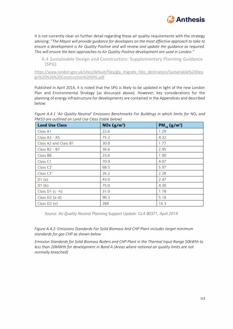
112
It is not currently clear on further detail regarding these air quality requirements with the strategy advising: “The Mayor will provide guidance for developers on the most effective approach to take to ensure a development is Air Quality Positive and will review and update the guidance as required. This will ensure the best approaches to Air Quality Positive development are used in London.”
A.4 Sustainable Design and Construction: Supplementary Planning Guidance (SPG)
https://www.london.gov.uk/sites/default/files/gla_migrate_files_destination/Sustainable%20Design%20%26%20Construction%20SPG.pdf Published in April 2014, it is noted that the SPG is likely to be updated in light of the new London Plan and Environmental Strategy (as discussed above). However; key considerations for the planning of energy infrastructure for developments are contained in the Appendices and described below: Figure A.4.1 ‘Air Quality Neutral’ Emissions Benchmarks For Buildings in which limits for NOx and PM10 are outlined on Land Use Class (table below)
Figure A.4.2: Emissions Standards For Solid Biomass And CHP Plant includes target minimum standards for gas CHP as shown below
Emission Standards for Solid Biomass Boilers and CHP Plant in the Thermal Input Range 50kWth to less than 20MWth for development in Band A (Areas where national air quality limits are not normally breached)

113
Emission Standards for Solid Biomass Boilers and CHP Plant in the Thermal Input Range 50kWth to less than 20MWth for development in Band B (Areas where national air quality limits are occasionally or regularly breached)
These two tables, particularly that for band B, require Low NOx versions of Combined Heat and Power plant, and potentially the addition of Selective Catalytic Reduction (SCR) plant with its associated space take, capital costs and operational costs. As discussed above, when considering the heat source hierarchy in areas where legal air quality limits are exceeded (such as to the North End of the Old Kent Road OAF) “any emissions related to energy generation will be equivalent or lower than those of an ultra-low NOx gas boiler”. The SPG gives the following requirement for Ultra Low NOx boilers: 4.3.21 Where individual and/or communal gas boilers are installed in commercial and domestic
buildings they should achieve a NOx rating of <40 mg NOx/kWh. Guidance issued by DCLG94 notes
that individual gas boilers with NOx emissions lower than 40 mg/kWh are now standard for many developers and hence no extra cost is incurred. Therefore, it is considered likely that if gas CHP is to be implemented in any energy solution, particularly to the North of the Old Kent Road OAF, the emission requirement will need to match or be lower than 40 mg NOx/kWh. CHP’s are not commonly quoted in mg NOx/kWh, standard reference emissions for engines are quoted as mg Nm-3 at 5% excess oxygen. The units need to be converted to understand the relationship between these. It is likely that this policy will curtail uptake of some reciprocating gas CHP. Normally aspirated units utilising Catalytic converters and large turbo charged units with Selective Catalytic reduction (SCR technology) are likely to be required to achieve this. Where SCR technology is utilised on CHP there may be opportunities to extend this to cleaning boiler flue gas emissions beyond 40 mg NOx/kWh to contribute towards the proposed zero NOx policy target. In addition:

114
If an assessment indicates that significant air quality effects may occur even when meeting the emission standards, additional measures (such as stack height increase, enforcement of more stringent standards etc.) should be considered in order to produce an acceptable level of impact. Where meeting these emission standards still does not allow the air quality neutral benchmarks to be met, further reduction or offsetting measures would be required.
A.4.1 Greater London Authority guidance on preparing energy assessments
https://www.london.gov.uk/sites/default/files/gla_guidance_on_preparing_energy_assessments_-_march_2016.pdf Published March 2016, this document does not incorporate the proposed changes within the New London Plan and as such is expected to be amended in due course. However, the general guidance regarding applicability of communal energy systems and selection of energy system once energy demand has been minimised is considered to remain in principal. In particular, the following points are applicable when considering district energy requirements: 11.13 Applicants must work on the assumption that a site (note: also known as communal) heat network will be required unless it can be clearly demonstrated that it is not applicable due to local circumstances. 11.26 Developers will be expected to provide a site heat network served by a single energy centre in order to future proof the development for easy connection to a wider heat network in the future. The type of heat source to be installed in the energy centre (e.g. CHP, heat pumps, boilers) will depend on the technical feasibility of different low carbon heat technologies and the carbon savings being targeted. 11.12 By ensuring the necessary infrastructure is in place and providing a single point of connection, a site-wide heat network served by a single energy centre helps to facilitate later connection of a development to an area-wide district heating network. It ensures that the connecting heat network infrastructure investment occurs at the construction stage, rather than retrofitting, with its higher costs, at a later date. The higher costs of retrofitting can have a detrimental impact on the business case for making a connection and, hence, make it less likely. 11.28 CHP is one of various technology options that could be selected to produce the heat to serve heat networks. The consideration of whether or not on-site CHP is an appropriate energy solution for a development will depend on the type and size of the development and whether a heat network is planned in the area. Regarding the requirement of assessing viability of a wider DHN if one is not already under development: 11.41 In line with Policy 5.6A (note: referencing the previous London Plan), where CHP is proposed, particularly on large developments, the applicant should investigate opportunities for supplying heat outside the site boundaries. If CHP could be made feasible by connecting to energy consumers beyond the site boundary then applicants are encouraged to consider this option. Applicants could look in particular for opportunities to link to existing developments to help reduce their carbon dioxide emissions and this could help developments that can’t meet their carbon reduction targets on-site to meet them off-site.

115
11.16 In line with the CIBSE Heat Networks: Code of Practice for the UK designers should aim for maximum secondary network flow and return temperatures of 70 degrees C and 40 degrees C respectively.
A.5 Local Policy
A.5.1 Southwark Core Strategy 2011
In effect since April 2011, the Core Strategy is one of the key documents within Southwark’s local development framework – although it should be noted that it is soon to be replaced by the New Southwark Plan. It is set within national policy guidelines, and describes the Council’s vision, spatial strategy and strategic policies through to 2026 to enforce sustainable development across the borough.
Strategic Policy 13 covers environment standards, setting out the following:
Our approach is
Development will help us live and work in a way that respects the limits of the planet’s natural resources, reduces pollution and damage to the environment and helps us adapt to climate change.
1. Requiring development to meet the highest possible environmental standards, including targets based on the Code for Sustainable Homes and BREEAM.
2. Requiring all new development to be designed and built to minimise greenhouse gas emissions across its lifetime. This will be achieved by applying the energy hierarchy
• Designing all developments so that they require as little energy as possible to build and use.
• Expecting all major developments to set up and/or connect to local energy generation networks where possible. We will develop local energy networks across Southwark.
• Requiring developments to use low and zero carbon sources of energy.
3. Enabling existing buildings to become more energy efficient and make use of low and zero carbon sources of energy.
Decentralised energy forms a key part of the Southwark’s low carbon energy strategy, with the implementation of CHP systems advocated. A map is provided showing potential locations of decentralised energy networks, as displayed within the following figure:

116
The Elephant and Castle energy network is currently being installed. There may be potential for interconnection between the networks at Elephant and Castle, Aylesbury and Old Kent Road, as they are in near proximity.
Overall key targets within the Core Strategy are as follows:
• Residential development should achieve at least Code for Sustainable Homes Level 4
• Community facilities, including schools, should achieve at least BREEAM “very good”.
• New health facilities must be BREEAM “excellent” and any refurbishment should achieve BREEAM “very good.”
• All other non-residential development should achieve at least BREEAM “excellent”.
It is not clear how the residential target has been interpreted following the scrapping of CfSH, however, this is updated in the New Southwark Plan.
The following targets apply to Major Developments:
• Major development should achieve a 44% saving in carbon dioxide emissions above the building regulations from energy efficiency, efficient energy supply and renewable energy generation.
• Major development must achieve a reduction in carbon dioxide of 20% from using on-site or local low and zero carbon sources of energy.
A.5.2 New Southwark Plan (NSP)
The NSP will replace the current local plan, comprising the Southwark Plan policies and the Core Strategy. A formal consultation on the proposed submission version of the new plan concluded on the 27th February 2018, and a new submission will occur in early 2019. The NSP will drive borough-wide planning and regeneration strategy up to 2033.
Relevant policies within the NSP are:
• P61: Environmental Standards
• P62: Energy
P61: Environmental Standards

117
The following text, taken from the New Southwark Plan, sets out energy efficiency requirements:
Policy 62: Energy
Section P62, energy, is set out in line with the Mayor of London’s energy hierarchy, thus:
i. Be lean (energy efficient design and construction); then ii. Be clean (low carbon energy supply); then iii. Be green (on-site renewable energy generation and storage).
Major development has the following “be lean” targets:
Incorporation of decentralised energy is also supported within the Plan, with the following requirements:
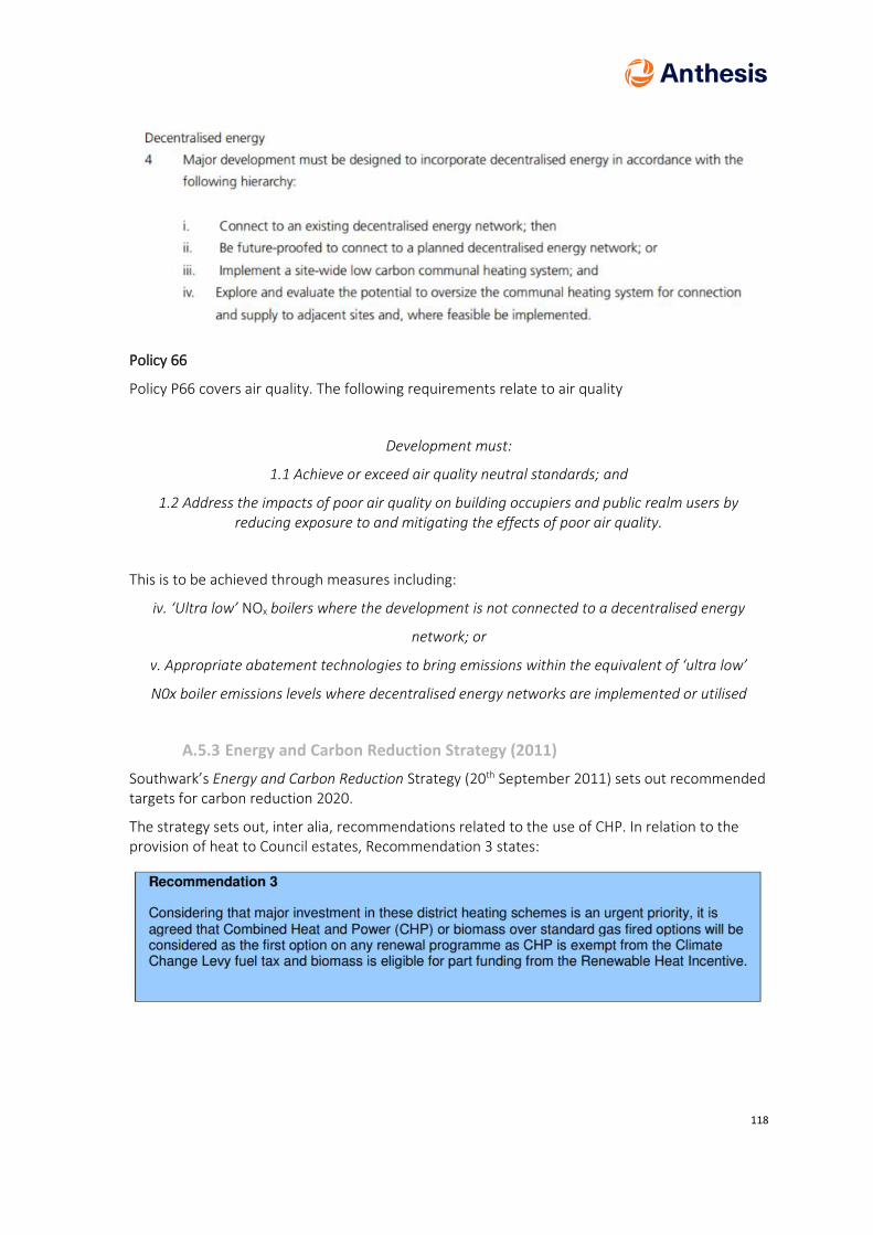
118
Policy 66
Policy P66 covers air quality. The following requirements relate to air quality
Development must:
1.1 Achieve or exceed air quality neutral standards; and
1.2 Address the impacts of poor air quality on building occupiers and public realm users by reducing exposure to and mitigating the effects of poor air quality.
This is to be achieved through measures including:
iv. ‘Ultra low’ NOx boilers where the development is not connected to a decentralised energy
network; or
v. Appropriate abatement technologies to bring emissions within the equivalent of ‘ultra low’
N0x boiler emissions levels where decentralised energy networks are implemented or utilised
A.5.3 Energy and Carbon Reduction Strategy (2011)
Southwark’s Energy and Carbon Reduction Strategy (20th September 2011) sets out recommended targets for carbon reduction 2020.
The strategy sets out, inter alia, recommendations related to the use of CHP. In relation to the provision of heat to Council estates, Recommendation 3 states:
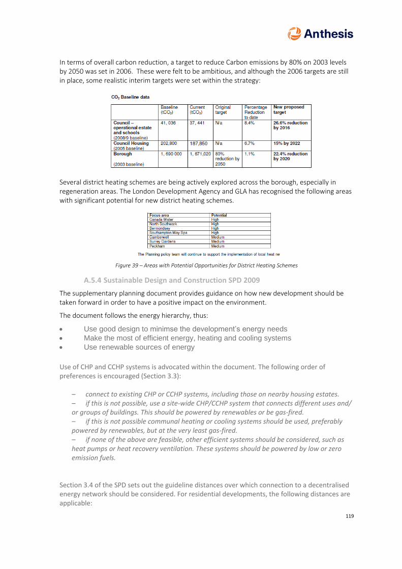
119
In terms of overall carbon reduction, a target to reduce Carbon emissions by 80% on 2003 levels by 2050 was set in 2006. These were felt to be ambitious, and although the 2006 targets are still in place, some realistic interim targets were set within the strategy:
Several district heating schemes are being actively explored across the borough, especially in regeneration areas. The London Development Agency and GLA has recognised the following areas with significant potential for new district heating schemes.
Figure 39 – Areas with Potential Opportunities for District Heating Schemes
A.5.4 Sustainable Design and Construction SPD 2009
The supplementary planning document provides guidance on how new development should be taken forward in order to have a positive impact on the environment.
The document follows the energy hierarchy, thus:
• Use good design to minimse the development’s energy needs
• Make the most of efficient energy, heating and cooling systems
• Use renewable sources of energy
Use of CHP and CCHP systems is advocated within the document. The following order of preferences is encouraged (Section 3.3):
– connect to existing CHP or CCHP systems, including those on nearby housing estates. – if this is not possible, use a site-wide CHP/CCHP system that connects different uses and/ or groups of buildings. This should be powered by renewables or be gas-fired. – if this is not possible communal heating or cooling systems should be used, preferably powered by renewables, but at the very least gas-fired. – if none of the above are feasible, other efficient systems should be considered, such as heat pumps or heat recovery ventilation. These systems should be powered by low or zero emission fuels.
Section 3.4 of the SPD sets out the guideline distances over which connection to a decentralised energy network should be considered. For residential developments, the following distances are applicable:

120
No Dwellings Distance
<20 50m
20-30 100m
31-40 150m
>40 200m Table 16 - Distances in Accordance to the Number of Dwellings
Page 12 Commercial and other non-residential development should connect if the development is within 200m of a decentralised energy system, unless it has been shown that it is inefficient to do. Where there is insufficient capacity to accommodate the heating demands, feasibility of upgrading the existing system should be considered. If a site is developed before a decentrlaised energy system is available, efficient temporary boiler plant can be used, with connection to the system as soon as possible. The document also provides energy consumption development standards. Note that residential development is listed in terms of Code for Sustainable Homes, which has since been scrapped.
• Residential development: Code Level 4 or equivalent, with level 3 as a minimum
• Non-residential: BREEAM “Very Good”
In terms of energy efficiency:
• By applying the energy hierarchy, development should achieve at least a 25% improvement over the Building Regulations energy efficiency standards current at the time of the application. Council procured housing should achieve a 44% improvement
In terms of energy supply:
• Developments must achieve a reduction in carbon dioxide emissions of 20% from onsite renewable energy generation (which can include sources of decentralised renewable energy) unless it can be demonstrated that such provision is not feasible.
In addition to the minimum standards, the preferred standards are set out as follows:
A.5.5 Old Kent Road Area Action Plan (AAP) (2017)
The Old Kent Road AAP provides the vision for how the Opportunity Area is to be developed over the next 20 years. It sets out the expected development quanta within each of the site allocations that forms part of the overall masterplan. In terms of policies relevant to the supply of energy, the following apply:
AAP11: Cleaner, greener, safer

121
Development must:
• Deliver an energy centre or link to one of Old Kent Road decentralised heat networks that are shown on Figure 10; and
• Not create pollutant hot spots on site or for adjacent sites. This must be demonstrated by 3D dynamic modelling. Where it is not feasible to avoid pollutant hot spots, we will require mitigation using zero and low carbon measures; and
• Provide electric vehicle fleets for commercial development;
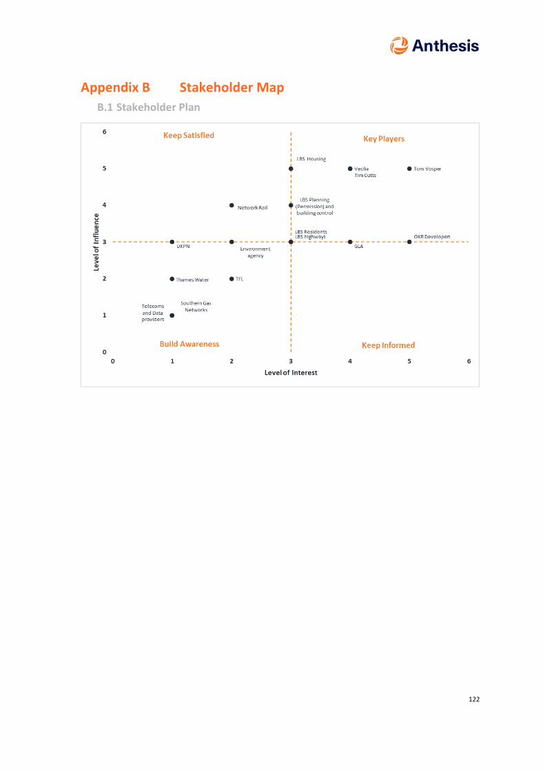
122
Appendix B Stakeholder Map
B.1 Stakeholder Plan

123
Appendix C Condition Surveys

124
Appendix D Cartography
D.1 Heat Map
D.2 Electrical Demand

125
Appendix E Pipework Route Details & HAZIDs
E.1 Contaminated Land Review
E.2 UXO
E.3 Routing Options

126
Appendix F Hydraulic Modelling
Total Pipe Length
Materials Cost Prelims, Commissioning, Mobilisation, GPR and Design
Project Management and Supervision
Total excl contingency Contingency
Phase 1 7,506 £10,194,564.31 £2,569,884 957,541 £13,721,989.72
£ 5,105,779.44
Phase 2 1,475 £2,060,938.75 £505,007 188,166 £2,754,111.21 £ 1,026,378.13
Phase 3 OKR 16 298 £271,470.00 £102,028 38,016 £411,514.33
£ 149,399.38
Phase 4 OKR 13 South
974 £830,346.50 £299,676 124,253 £1,254,275.30
£ 452,008.81
Phase 5 OKR 13 North
76 £59,377.50 £26,021 9,695 £95,093.50
£ 34,159.27
Phase 6 OKR 11 1,023 £1,353,189.38 £350,252 130,504 £1,833,945.60
£ 681,376.56
Phase 7 NW LINK 930 £1,063,312.50 £318,411 118,640 £1,500,363.61
£ 552,689.37
Phase 8 OKR 3&4 896 £690,250.00 £306,770 114,303 £1,111,322.90
£ 398,808.04
Phase 9 OKR 2 518 £453,725.00 £177,351 66,081 £697,157.77
£ 252,430.58
Total PM and Supervision
£ 1,747,200.00

127
Sum Length Phase 1 Phase 2 Phase 3 Phase 4 Phase 5 Phase 6 Phase 7 Phase 8 Phase 9
DN32 13 - - - - - - - -
DN40 - - - - - - - 266 -
DN50 222 125 - 76 - 133 - - -
DN65 384 95 - - - - - - -
DN80 220 23 - 452 40 - - - -
DN100 1,033 100 200 122 36 - - - 518
DN125 1,375 - 98 - - - - 630 -
DN150 686 186 - 264 - - 930 - -
DN200 795 - - 60 - 496 - - -
DN250 575 63 - - - 394 - - -
DN300 303 883 - - - - - - -
DN400 752 - - - - - - - -
DN450 1,148 - - - - - - - -
Route Section Length (m) Flow only
Nominal Pipe Diameter (DN)
Phase Jointing -price F&R Civils -price F&R
Materials -price F&R Total
P01 680 450 Phase 1 £146,200.00 £973,760.00 £312,800.00 £1,432,760.00
P02 135 450 Phase 1 £29,240.00 £276,750.00 £62,100.00 £368,090.00
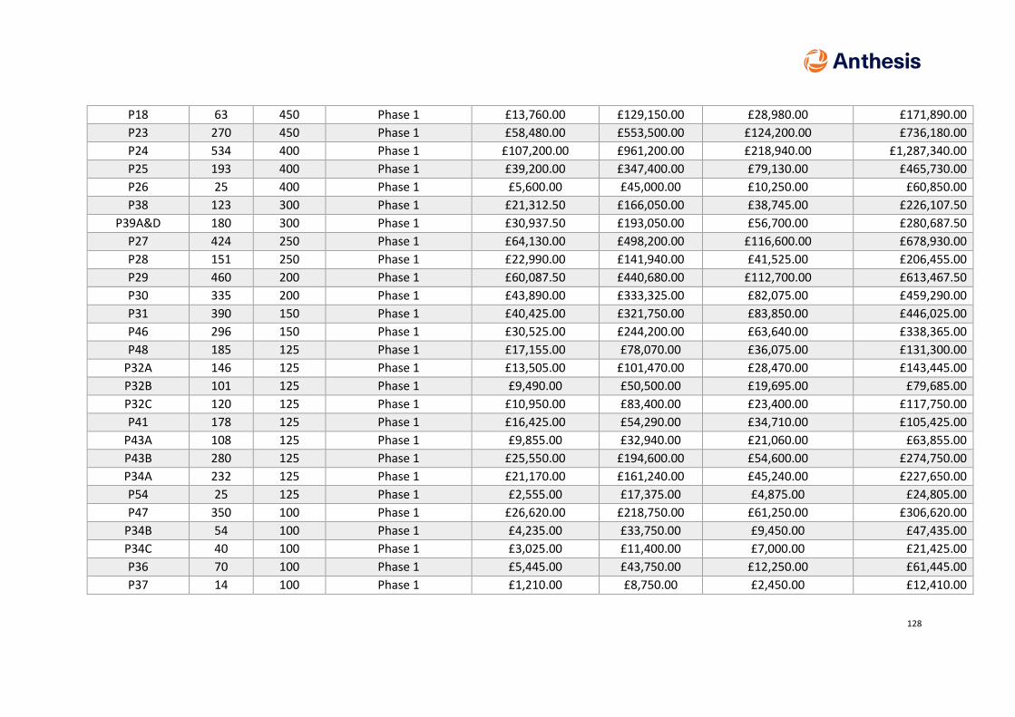
128
P18 63 450 Phase 1 £13,760.00 £129,150.00 £28,980.00 £171,890.00
P23 270 450 Phase 1 £58,480.00 £553,500.00 £124,200.00 £736,180.00
P24 534 400 Phase 1 £107,200.00 £961,200.00 £218,940.00 £1,287,340.00
P25 193 400 Phase 1 £39,200.00 £347,400.00 £79,130.00 £465,730.00
P26 25 400 Phase 1 £5,600.00 £45,000.00 £10,250.00 £60,850.00
P38 123 300 Phase 1 £21,312.50 £166,050.00 £38,745.00 £226,107.50
P39A&D 180 300 Phase 1 £30,937.50 £193,050.00 £56,700.00 £280,687.50
P27 424 250 Phase 1 £64,130.00 £498,200.00 £116,600.00 £678,930.00
P28 151 250 Phase 1 £22,990.00 £141,940.00 £41,525.00 £206,455.00
P29 460 200 Phase 1 £60,087.50 £440,680.00 £112,700.00 £613,467.50
P30 335 200 Phase 1 £43,890.00 £333,325.00 £82,075.00 £459,290.00
P31 390 150 Phase 1 £40,425.00 £321,750.00 £83,850.00 £446,025.00
P46 296 150 Phase 1 £30,525.00 £244,200.00 £63,640.00 £338,365.00
P48 185 125 Phase 1 £17,155.00 £78,070.00 £36,075.00 £131,300.00
P32A 146 125 Phase 1 £13,505.00 £101,470.00 £28,470.00 £143,445.00
P32B 101 125 Phase 1 £9,490.00 £50,500.00 £19,695.00 £79,685.00
P32C 120 125 Phase 1 £10,950.00 £83,400.00 £23,400.00 £117,750.00
P41 178 125 Phase 1 £16,425.00 £54,290.00 £34,710.00 £105,425.00
P43A 108 125 Phase 1 £9,855.00 £32,940.00 £21,060.00 £63,855.00
P43B 280 125 Phase 1 £25,550.00 £194,600.00 £54,600.00 £274,750.00
P34A 232 125 Phase 1 £21,170.00 £161,240.00 £45,240.00 £227,650.00
P54 25 125 Phase 1 £2,555.00 £17,375.00 £4,875.00 £24,805.00
P47 350 100 Phase 1 £26,620.00 £218,750.00 £61,250.00 £306,620.00
P34B 54 100 Phase 1 £4,235.00 £33,750.00 £9,450.00 £47,435.00
P34C 40 100 Phase 1 £3,025.00 £11,400.00 £7,000.00 £21,425.00
P36 70 100 Phase 1 £5,445.00 £43,750.00 £12,250.00 £61,445.00
P37 14 100 Phase 1 £1,210.00 £8,750.00 £2,450.00 £12,410.00

129
P45 120 100 Phase 1 £9,075.00 £75,000.00 £21,000.00 £105,075.00
P53 80 100 Phase 1 £6,050.00 £50,000.00 £14,000.00 £70,050.00
P33 152 100 Phase 1 £11,495.00 £95,000.00 £26,600.00 £133,095.00
P39B,C,E 153 100 Phase 1 £11,797.50 £43,605.00 £26,775.00 £82,177.50
P51 130 80 Phase 1 £7,441.50 £64,350.00 £18,850.00 £90,641.50
P52 70 80 Phase 1 £4,059.00 £34,650.00 £10,150.00 £48,859.00
P44 20 80 Phase 1 £1,127.50 £7,450.00 £2,900.00 £11,477.50
P50 133 65 Phase 1 £5,797.00 £56,525.00 £13,965.00 £76,287.00
P42 51 65 Phase 1 £2,216.50 £21,675.00 £5,355.00 £29,246.50
A11 61 65 Phase 1 £2,728.00 £18,910.00 £6,405.00 £28,043.00
A12 139 65 Phase 1 £5,967.50 £43,090.00 £14,595.00 £63,652.50
P49 81 50 Phase 1 £2,887.50 £15,946.88 £6,885.00 £25,719.38
P35 141 50 Phase 1 £4,950.00 £21,810.94 £11,985.00 £38,745.94
P40 13 32 Phase 1 £352.00 £975.00 £715.00 £2,042.00
P13B 130 300 Phase 2 £22,687.50 £103,350.00 £40,950.00 £166,987.50
P13A 161 300 Phase 2 £28,187.50 £217,350.00 £50,715.00 £296,252.50
P14A,C 592 300 Phase 2 £101,750.00 £799,200.00 £186,480.00 £1,087,430.00
P11B 63 250 Phase 2 £9,680.00 £74,025.00 £17,325.00 £101,030.00
A 6.1.2.4 67 150 Phase 2 £7,012.50 £55,275.00 £14,405.00 £76,692.50
A 6.3 15 100 Phase 2 £1,210.00 £9,375.00 £2,625.00 £13,210.00
P12C 85 100 Phase 2 £6,655.00 £53,125.00 £14,875.00 £74,655.00
P12B 23 80 Phase 2 £1,353.00 £11,385.00 £3,335.00 £16,073.00
A6.5 15 65 Phase 2 £682.00 £6,375.00 £1,575.00 £8,632.00
P12A 80 65 Phase 2 £3,410.00 £34,000.00 £8,400.00 £45,810.00
P14B 87 50 Phase 2 £3,025.00 £17,128.13 £7,395.00 £27,548.13
P15 38 50 Phase 2 £1,375.00 £5,878.13 £3,230.00 £10,483.13
A07 119 150 Phase 2 £12,375.00 £98,175.00 £25,585.00 £136,135.00

130
P21 63 125 Phase 3 £5,840.00 £43,785.00 £12,285.00 £61,910.00
P22 15 125 Phase 3 £1,460.00 £10,425.00 £2,925.00 £14,810.00
P20 20 125 Phase 3 £1,825.00 £13,900.00 £3,900.00 £19,625.00
P19 200 100 Phase 3 £15,125.00 £125,000.00 £35,000.00 £175,125.00
P17D 40 200 Phase 4 £5,225.00 £39,800.00 £9,800.00 £54,825.00
P17E 20 200 Phase 4 £2,612.50 £19,900.00 £4,900.00 £27,412.50
P17A 90 150 Phase 4 £9,487.50 £74,250.00 £19,350.00 £103,087.50
A04 174 150 Phase 4 £18,150.00 £143,550.00 £37,410.00 £199,110.00
P17B 67 100 Phase 4 £5,142.50 £41,875.00 £11,725.00 £58,742.50
P17C 40 100 Phase 4 £3,025.00 £25,000.00 £7,000.00 £35,025.00
OKR13A connection
15 100 Phase 4 £1,210.00 £9,375.00 £2,625.00 £13,210.00
A03 452 80 Phase 4 £25,481.50 £223,740.00 £65,540.00 £314,761.50
A05 58 50 Phase 4 £2,062.50 £11,418.75 £4,930.00 £18,411.25
OKR13 K 18 50 Phase 4 £687.50 £3,543.75 £1,530.00 £5,761.25
P17F 36 100 Phase 5 £2,722.50 £22,500.00 £6,300.00 £31,522.50
OKR E,F,M 20 80 Phase 5 £1,127.50 £9,900.00 £2,900.00 £13,927.50
OKR G,H,O 20 80 Phase 5 £1,127.50 £9,900.00 £2,900.00 £13,927.50
P10 170 250 Phase 6 £26,015.00 £199,750.00 £46,750.00 £272,515.00
P11A 224 250 Phase 6 £33,880.00 £263,200.00 £61,600.00 £358,680.00
P04 496 200 Phase 6 £64,790.00 £493,520.00 £121,520.00 £679,830.00
P16 133 50 Phase 6 £4,675.00 £26,184.38 £11,305.00 £42,164.38
P05 930 150 Phase 7 £96,112.50 £767,250.00 £199,950.00 £1,063,312.50
P06 475 125 Phase 8 £43,435.00 £330,125.00 £92,625.00 £466,185.00
P08 266 40 Phase 8 £8,040.00 £45,220.00 £18,620.00 £71,880.00
P09 155 125 Phase 8 £14,235.00 £107,725.00 £30,225.00 £152,185.00
P07 518 100 Phase 9 £39,325.00 £323,750.00 £90,650.00 £453,725.00
A08 23 100 £1,815.00 £6,555.00 £4,025.00 £12,395.00
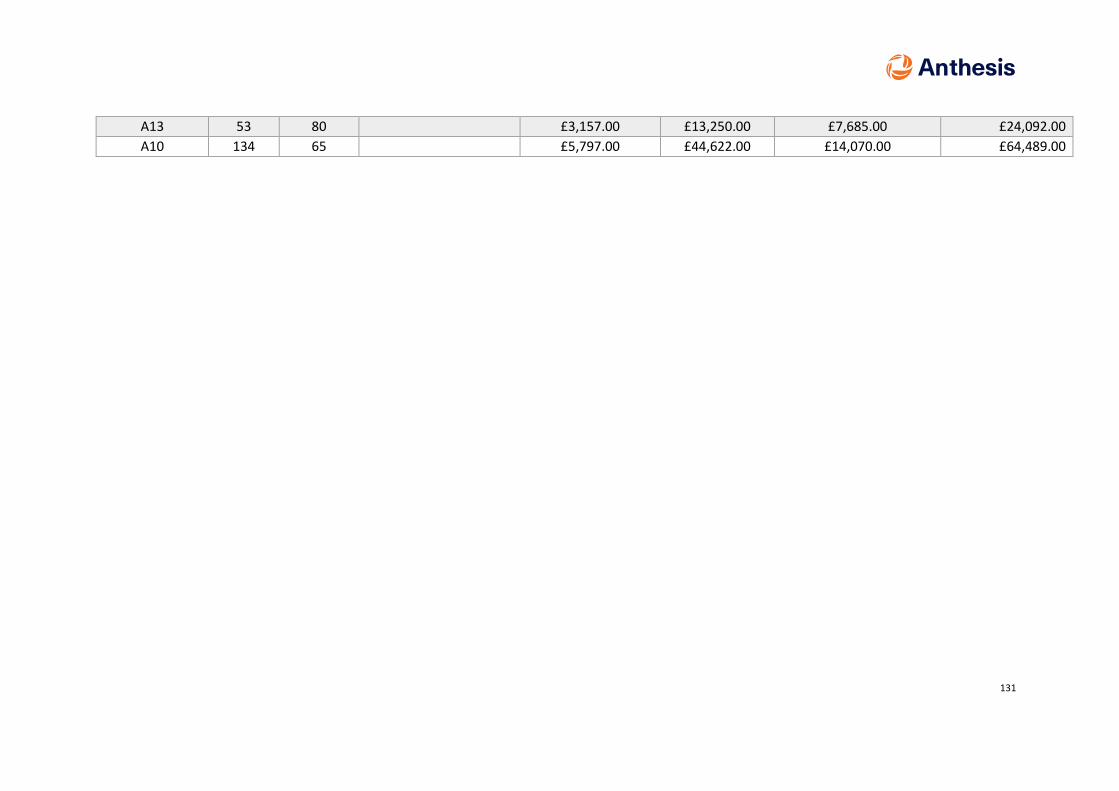
131
A13 53 80 £3,157.00 £13,250.00 £7,685.00 £24,092.00
A10 134 65 £5,797.00 £44,622.00 £14,070.00 £64,489.00

132
Appendix G Utility Infrastructure Review

133
Appendix H Implementation Plan